US9384615B2 - Apparatus and method for sorting coins - Google Patents
Apparatus and method for sorting coins Download PDFInfo
- Publication number
- US9384615B2 US9384615B2 US14/638,160 US201514638160A US9384615B2 US 9384615 B2 US9384615 B2 US 9384615B2 US 201514638160 A US201514638160 A US 201514638160A US 9384615 B2 US9384615 B2 US 9384615B2
- Authority
- US
- United States
- Prior art keywords
- coin
- coins
- unit
- conveying
- ejector
- Prior art date
- Legal status (The legal status is an assumption and is not a legal conclusion. Google has not performed a legal analysis and makes no representation as to the accuracy of the status listed.)
- Active
Links
- 238000000034 method Methods 0.000 title claims description 21
- 238000003860 storage Methods 0.000 claims description 28
- 238000011144 upstream manufacturing Methods 0.000 claims description 10
- 238000010008 shearing Methods 0.000 claims description 8
- 239000000463 material Substances 0.000 claims description 7
- 239000000203 mixture Substances 0.000 claims description 7
- 239000000956 alloy Substances 0.000 claims description 4
- 229910045601 alloy Inorganic materials 0.000 claims description 4
- 238000001514 detection method Methods 0.000 description 4
- 238000004064 recycling Methods 0.000 description 4
- 230000003287 optical effect Effects 0.000 description 2
- 230000006978 adaptation Effects 0.000 description 1
- 230000000052 comparative effect Effects 0.000 description 1
- 238000010276 construction Methods 0.000 description 1
- 238000000151 deposition Methods 0.000 description 1
- 238000007599 discharging Methods 0.000 description 1
- 238000009434 installation Methods 0.000 description 1
- 230000003993 interaction Effects 0.000 description 1
- 238000012423 maintenance Methods 0.000 description 1
- 238000004519 manufacturing process Methods 0.000 description 1
- 238000012986 modification Methods 0.000 description 1
- 230000004048 modification Effects 0.000 description 1
- 238000000926 separation method Methods 0.000 description 1
Images


Classifications
-
- G—PHYSICS
- G07—CHECKING-DEVICES
- G07D—HANDLING OF COINS OR VALUABLE PAPERS, e.g. TESTING, SORTING BY DENOMINATIONS, COUNTING, DISPENSING, CHANGING OR DEPOSITING
- G07D3/00—Sorting a mixed bulk of coins into denominations
- G07D3/14—Apparatus driven under control of coin-sensing elements
-
- G—PHYSICS
- G07—CHECKING-DEVICES
- G07D—HANDLING OF COINS OR VALUABLE PAPERS, e.g. TESTING, SORTING BY DENOMINATIONS, COUNTING, DISPENSING, CHANGING OR DEPOSITING
- G07D1/00—Coin dispensers
-
- G—PHYSICS
- G07—CHECKING-DEVICES
- G07D—HANDLING OF COINS OR VALUABLE PAPERS, e.g. TESTING, SORTING BY DENOMINATIONS, COUNTING, DISPENSING, CHANGING OR DEPOSITING
- G07D3/00—Sorting a mixed bulk of coins into denominations
- G07D3/12—Sorting coins by means of stepped deflectors
- G07D3/121—Sorting coins by means of stepped deflectors arranged on inclined paths
- G07D3/123—Sorting coins by means of stepped deflectors arranged on inclined paths the coins being deflected off rails
- G07D3/125—Sorting coins by means of stepped deflectors arranged on inclined paths the coins being deflected off rails by moving deflectors
-
- G—PHYSICS
- G07—CHECKING-DEVICES
- G07D—HANDLING OF COINS OR VALUABLE PAPERS, e.g. TESTING, SORTING BY DENOMINATIONS, COUNTING, DISPENSING, CHANGING OR DEPOSITING
- G07D5/00—Testing specially adapted to determine the identity or genuineness of coins, e.g. for segregating coins which are unacceptable or alien to a currency
- G07D5/02—Testing the dimensions, e.g. thickness, diameter; Testing the deformation
-
- G—PHYSICS
- G07—CHECKING-DEVICES
- G07D—HANDLING OF COINS OR VALUABLE PAPERS, e.g. TESTING, SORTING BY DENOMINATIONS, COUNTING, DISPENSING, CHANGING OR DEPOSITING
- G07D5/00—Testing specially adapted to determine the identity or genuineness of coins, e.g. for segregating coins which are unacceptable or alien to a currency
- G07D5/08—Testing the magnetic or electric properties
-
- G—PHYSICS
- G07—CHECKING-DEVICES
- G07D—HANDLING OF COINS OR VALUABLE PAPERS, e.g. TESTING, SORTING BY DENOMINATIONS, COUNTING, DISPENSING, CHANGING OR DEPOSITING
- G07D9/00—Counting coins; Handling of coins not provided for in the other groups of this subclass
-
- G—PHYSICS
- G07—CHECKING-DEVICES
- G07D—HANDLING OF COINS OR VALUABLE PAPERS, e.g. TESTING, SORTING BY DENOMINATIONS, COUNTING, DISPENSING, CHANGING OR DEPOSITING
- G07D9/00—Counting coins; Handling of coins not provided for in the other groups of this subclass
- G07D9/008—Feeding coins from bulk
-
- G—PHYSICS
- G07—CHECKING-DEVICES
- G07D—HANDLING OF COINS OR VALUABLE PAPERS, e.g. TESTING, SORTING BY DENOMINATIONS, COUNTING, DISPENSING, CHANGING OR DEPOSITING
- G07D9/00—Counting coins; Handling of coins not provided for in the other groups of this subclass
- G07D9/06—Devices for stacking or otherwise arranging coins on a support, e.g. apertured plate for use in counting coins
Definitions
- the invention relates to a device for sorting coins, the diameter and thickness of which are within predefined size ranges, containing a storage container for unsorted coins, containing at least one coin conveying unit having two parallel, jointly driven, endlessly circulating pulling means, wherein an upper run of the pulling means, that conveys the coins upwards from the storage container and is oriented such that it raises in a conveying direction, forms part of the wall of the storage container, with a sliding bar extended in the conveying direction for supporting the coins during conveying, wherein the sliding bar is arranged between the pulling means in the region of the upper run, and with coin receptacles for the conveyed coins, wherein the coin receptacles have driver pins provided on the pulling means and assigned to one another in pairs, which project beyond the sliding bar by an extent exceeding the predefined greatest coin thickness, containing a coin separating unit for separating the coins conveyed from the storage container in the coin receptacles, with a shearing device for coins lying axially above one another in
- the invention further relates to a method for sorting coins provided in an unsorted manner in a storage container, wherein the coins are conveyed out of the storage container by means of a coin conveying unit, wherein the coins are separated by means of a coin separating unit in such a manner that, in the coin receptacles of the coin conveying unit receiving the coins when conveyed, only one coin is provided respectively, and wherein a characteristic feature of the coins is detected in a coin recognition unit for identifying different types of coins.
- a device of this type is known from EP 1 450 314 B1.
- the device is used for separating coins and is in particular applied in coin receiving machines. For example, after business opening hours, business people may use a self-service receiving machine for filling in unsorted coins into a funnel-shaped storage container.
- the entered coins are separated upon reception, identified with regard to their value and are counted. The overall amount of the coins may subsequently for example be credited to a business account of the user.
- the entered coins are stored in an unsorted manner in a single collection container, wherein in the collection container, coins from different users are stored jointly. Foreign currency coins and non-accepted means of payment such as buttons are sorted out and returned to the user.
- the collection container is for example emptied on a daily basis.
- the coins collected in the collecting container are again separated and sorted. This can for example be carried out manually in the branch bank or in an automated manner in a central bank. Even though such receiving machines provided with the device for separating coins principally have proved their worth, it is desirable to simplify the return of the coins, which have been entered into the receiving machine, into the cash flow.
- the invention in connection with an aspect of the invention is characterized in that the discharge unit is designed as a discharge unit for discharging coins of one single type and has at least one ejector, wherein the at least one ejector is controlled by a control unit in such a manner that the coins identified by the coin recognition unit are supplied to different collecting containers in accordance with the identified characteristic feature.
- the invention is especially advantageous since, as a consequence of the single-type storage of the entered coins, it is not necessary to separate and identify the coins anew.
- the sorting takes place directly following the identification of the coins in the receiving machine itself. It is not necessary to manually sort the coins or separate and sort them anew in an automated manner, for example in a central bank, such that finally it is not necessary to transport the coins to a central bank.
- a control unit interacts with a drive unit actuating the pulling means or respectively with a detection unit for detecting a conveying speed of the coins, with the coin recognition unit and the at least one ejector in such a manner that a point in time for actuating the ejector is determinable taking into consideration the conveying speed of the coins and a distance of the ejector from the coin recognition unit or another point of reference of the device.
- the point in time for actuating the ejector can especially exactly be determined by interrelating the actual conveying speed of the coins with the distance of the ejector from the coin recognition unit.
- the diameter of the coins to be sorted can serve as a further parameter for determining the time of actuation. In this way, it is taken account of the fact that after having left the coin recognition unit, coins having a great diameter reach an operating area of the ejector sooner than coins having a small diameter.
- a guiding unit is arranged between the at least one ejector and the collecting containers.
- the coins ejected from the coin receptacles are suppliable to the collecting containers.
- the guiding unit increases the accuracy of the sorting since by providing the guiding unit it can be prevented that sorting errors occur.
- the guiding unit may for example be provided with at least a guiding channel for the ejected coins, an inclined surface serving as a coin slide or a guiding tube adjusted to the diameter of the coins.
- the coins can be passively guided in the guiding unit in the direction of the collecting containers.
- a plurality of ejectors is provided that are arranged in series in the conveying direction.
- the number of ejectors is in correspondence with the number of types of coins or the number of collecting containers, respectively.
- the sorting of the coins is performed in an highly accurate manner if exactly one ejector is provided for every type of coins.
- the ejector may be designed as a quasi-analogue ejector, which merely makes a difference between the operating conditions of “ejection” and “no ejection”. Different operating conditions for ejecting different types of coins by means of one single ejector can be avoided and the risk of an erroneous sorting of the coins is reduced.
- a plurality of ejectors and a plurality of detectors are arranged in series in an alternating manner, wherein by means of the detectors it can be verified whether the coins are duly ejected.
- detectors each of which is provided downstream of an ejector, it can be reviewed if the ejectors function in an unobjectionable manner and an erroneous sorting can immediately be detected.
- detectors can be arranged immediately upstream of the respective ejectors.
- the point in time for actuating the ejector can be determined exactly and occasionally depending on the conveying speed.
- the discharge unit comprises a plurality of discharge modules arranged in series in the conveying direction.
- Each of the discharge modules has an ejector and a detector downstream of the ejector and is assigned to exactly one collecting container.
- the device can easily be adapted to the set of coins in different countries. For example by removing two modules, a device for sorting coins originally intended for use in the Euro zone and thus having eight discharge modules, namely for the 1 Cent coin, the 2 Cent coin, the 5 Cent coin, the 10 Cent coin, the 50 Cent coin, the 1 Euro coin and the 2 Euros coin, can be adapted to a currency area merely having six different types of coins.
- the effort that has to be made for the constructive adaptation of the device is limited, thus that consequently the production of the device is particularly cost-effective.
- the diameter of the coins is detected by the coin recognition unit as the characteristic feature of the coins.
- the diameter can for example be detected in a particular easy way by means of an optical sensor unit. There is only little risk of an erroneous detection. Comparative data for determining the types of coins by way of determining the diameter can for example be stored in the control unit.
- a material composition of the coins is detected as the characteristic feature of the coins.
- an authenticity check of the coins can be performed.
- the material composition of the coins can for example be detected by an electromagnet alloy analysis. Consequently, it is possible to integrate the determination of value of the coins, in which an at least elementary authenticity check is required, as well as the sorting function in one single device. Hence, the constructive effort as well as the installation space requirements can be reduced.
- the invention in connection with another aspect of the invention, is characterized in that the coins are then separated in a single-type manner, wherein the coins are ejected from the coin receptacles and supplied to different collecting containers depending on the type of coin.
- the coins can be supplied to a coin separating unit, a coin recognition unit and a unit for single-type sorting of the coins by means of one single coin conveying unit. Subsequently, the coins are stored in a single-type manner in individual collecting containers. On the one hand, after sorting, the coins can be dispensed anew for realizing a coin recycling machine. On the other hand, the effort made for post-treatment of the coins after their reception is reduced, since it is not necessary to separate the coins anew prior to their subsequent sorting.
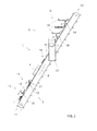
- FIG. 1 is a schematic illustration of a device for sorting coins in a top plan view
- FIG. 2 is a side view of the device according to FIG. 1 .
- Substantial functional units of a device for sorting coins 1 are a coin conveying unit 2 designed in the form of an inclined conveyor for the coins 1 , a coin separating unit 3 for separating the coins 1 conveyed on the coin conveying unit 2 , a coin recognition unit 4 for identifying different types of coins, a discharge unit 5 for single-type dischargement of the coins 1 as well as a guiding unit 6 .
- Such device is for example used in coin receiving machines for separating, identifying and sorting coins 1 inserted by users in an unsorted manner.
- the receiving machine may for example be designed to be a self-service machine and be provided in a foyer of a bank. These self-service machines can be used by business people for depositing their daily receipts after business hours to have them credited to their business account.
- the coin conveying unit 2 is used to convey unsorted coins 1 provided in a storage container, not illustrated, upwards out of the storage container.
- the coin conveying unit 2 has two parallely oriented, jointly driven, endlessly circulating pulling means 7 .
- An upper run 9 of the pulling means 7 that conveys the coins 1 upwards from the storage container and that is oriented to raise in a conveying direction 8 herein defines part of the wall of the storage container.
- the coins 1 are provided in a plurality of coin receptacles 10 arranged in series in the conveying direction 8 .
- Each of the coin receptacles 10 has two driving pins 11 assigned to one another in pairs and provided on the pulling means 7 in a way so as to project therefrom.
- the coins 1 radially abut on the driving pins 11 .
- the coins 1 are supported at an even side thereof by a sliding bar 12 extending in the conveying direction 8 .
- the sliding bar 12 is arranged between the pulling means 7 in the region of the upper run 9 .
- the driving pins 11 project beyond the sliding bar 12 by an extent exceeding the predefined greatest coin thickness.
- the coin separating unit 3 is assigned to the coin conveying unit 2 in a lower region thereof.
- the coin separating unit 3 has a shearing device 13 as well as a return device 14 in the coin receptacles 10 .
- the shearing device 13 serves for separating coins 1 lying axially above one another in the coin receptacles 10 .
- the shearing device 13 is constituted by a run-on ramp 15 assigned to the sliding bar 12 .
- the run-on ramp 15 is designed to protrude as against the sliding bar 12 , wherein a height of the run-on ramp 15 raising in the conveying direction 8 is smaller than the projection of the driving pins 11 beyond the sliding bar 12 and greater than the difference between the projection of the driving pins and the smallest predefined coin thickness.
- the return device 14 is arranged downstream of the shearing device 13 .
- the substantial parts of the return device 14 are a signal generator 16 and a returner 17 arranged downstream of the signal generator 16 .
- the signal generator 16 serves to detect the extension of the coins 1 , which are conveyed in the coin receptacle 10 , in the conveying direction 8 . If the extension of the coins 1 in the conveying direction 8 is greater than the maximum coin diameter, it can be concluded that, as seen in the conveying direction 8 , in one single coin receptacle 10 two or more coins 1 are arranged in series. In this case, the surplus coins 1 conveyed are returned back into the storage container from the coin receptacles 10 by means of the returner 17 .
- the diameter of the coins 1 is detected by means of an optical sensor unit 18 .
- ejectors 19 and detectors 20 are arranged in series in an alternating manner, wherein, as seen in the conveying direction 8 , a detector 20 is arranged downstream of every ejector 19 .
- the ejectors 19 serve to eject the coins 1 , which are conveyed in the coin receptacles 10 , out of the coin receptacles 10 and to supply them to the guiding unit 6 .
- the detectors 20 are provided in order to verify whether the coins 1 are duly ejected.
- the discharge unit 5 is constituted to be a modular discharge unit 5 having a plurality of discharge modules 21 arranged in series in the conveying direction 8 . Every discharge module 21 has an ejector 19 and a detector 20 arranged downstream of the ejector 19 . As seen in the conveying direction 8 , seven discharge modules 21 are arranged in series. Every discharge unit 21 serves to eject exactly one type of coins from out of the coin receptacles 10 of the coin conveying unit 2 .
- exactly one guiding channel 22 of the guiding unit 6 that serves as guiding means for the ejected coins 1 , is assigned to every discharge module 21 , wherein for clarity reasons not all of these seven guiding channels 22 are illustrated and wherein the construction and function of the guiding unit 6 is outlined in principle by way of example of four guiding channels 22 .
- the coins 1 of one single type slide into a respective collecting container not shown.
- the coins 1 can be provided to be of one single type, however unsorted or of one single type in a geometrical order, for example as a stack of coins.
- the collecting containers can be constructed for example to have a tubular shape, wherein an inner diameter of the collecting containers is adjusted to the diameter of the respective type of coins to be stored.
- the guiding unit 6 can be provided with guiding means having a V-shaped cross section or a bent cross section of any other type for forming a hollow guide.
- the guiding unit 6 can be provided with guiding means having a closed cross sectional profile, in particular with circular guiding means.
- the coins 1 having been conveyed out of the storage container and having been separated by means of the coin separating unit 3 and having been identified by the coin recognition unit 4 are moved into the operating area of the discharge unit 5 . They are conveyed by the coin conveying unit 2 until they reach the operating area of the ejector 19 predefined for the respective type of coins.
- the coin 1 reaches the operating area of the ejector 19 which it is assigned to, it is ejected thereby from the coin receptacle 10 and, via the guiding channel 22 the ejector 19 is assigned to, is supplied to the collecting container provided for storing the respective type of coins.
- the detector 20 arranged immediately downstream of the ejector 19 it can be verified whether the coin 1 has correctly been discharged.
- coins 1 are conveyed that cannot be identified by means of the coin recognition unit 4 , the coins 1 are conveyed beyond all discharge modules 21 to reach a further collecting container via an upper discharge end 23 of the coin conveying unit 2 . Those coins may for example be re-dispensed to the user from the further collecting container.
- the ejectors 19 are controlled by a control unit not illustrated.
- the control unit interacts with the coin recognition unit 4 .
- the control unit may interact with a detection unit not shown for detecting a conveying speed of the coins 1 .
- the conveying speed of the coins 1 being known, the point in time for actuating the ejector 19 can be determined under consideration of both the conveying speed and the distance of the ejector 19 from the coin recognition unit 4 or from any other—preferably stationary—point of reference of the device.
- the coin diameter of the type of coins respectively to be ejected can be taken into consideration in determining the point in time of ejection.
- the conveying speed can be detected for example by means of suitable sensors or can be established by an interaction of the control unit with a drive unit for the pulling means 7 not shown.
- the point in time for actuating the ejector can be determined by a detector 20 arranged upstream of the respective ejector 10 .
- the detector 20 which is preferably situated in the region of the sliding bar 12 in immediate proximity of the ejector 19 which is assigned to it, can signalize the immediately imminent entrance of the coin 1 into the operating area of the ejector 19 and trigger the ejector 19 with a time delay that has been predefined or is determinable in a further parameter.
- the detector 20 arranged downstream of an ejector 19 that is not the last one can have two functions.
- the downstream detector 20 can function as a trigger for the ejector 19 that comes next in the conveying direction 8 .
- it can be used to verify the correct ejection of a coin 1 by means of the ejector 19 that is arranged upstream thereof.
- each of the ejectors 19 is individually controllable by the control unit.
- an authenticity check of the coins 1 by means of the device according to the invention is dispensed with.
- Such authenticity check can be carried out in combination with a value-related detection of the entered coins 1 by means of a separate device.
- a coin separating device known from prior art can be arranged upstream of the device according to the invention.
- the coins are supplied to the storage container of the device according to the invention to subsequently be sorted in a single-type manner.
Abstract
Description
Claims (18)
Priority Applications (1)
| Application Number | Priority Date | Filing Date | Title |
|---|---|---|---|
| US14/638,160 US9384615B2 (en) | 2011-04-07 | 2015-03-04 | Apparatus and method for sorting coins |
Applications Claiming Priority (6)
| Application Number | Priority Date | Filing Date | Title |
|---|---|---|---|
| DE102011001870A DE102011001870A1 (en) | 2011-04-07 | 2011-04-07 | Apparatus and method for sorting coins |
| DE102011001870 | 2011-04-07 | ||
| DE102011001870.0 | 2011-04-07 | ||
| US14/009,356 US8998686B2 (en) | 2011-04-07 | 2012-04-05 | Apparatus and method for sorting coins |
| PCT/EP2012/056264 WO2012136755A1 (en) | 2011-04-07 | 2012-04-05 | Apparatus and method for sorting coins |
| US14/638,160 US9384615B2 (en) | 2011-04-07 | 2015-03-04 | Apparatus and method for sorting coins |
Related Parent Applications (2)
| Application Number | Title | Priority Date | Filing Date |
|---|---|---|---|
| PCT/EP2012/056264 Division WO2012136755A1 (en) | 2011-04-07 | 2012-04-05 | Apparatus and method for sorting coins |
| US14/009,356 Division US8998686B2 (en) | 2011-04-07 | 2012-04-05 | Apparatus and method for sorting coins |
Publications (2)
| Publication Number | Publication Date |
|---|---|
| US20150221154A1 US20150221154A1 (en) | 2015-08-06 |
| US9384615B2 true US9384615B2 (en) | 2016-07-05 |
Family
ID=46027915
Family Applications (2)
| Application Number | Title | Priority Date | Filing Date |
|---|---|---|---|
| US14/009,356 Active US8998686B2 (en) | 2011-04-07 | 2012-04-05 | Apparatus and method for sorting coins |
| US14/638,160 Active US9384615B2 (en) | 2011-04-07 | 2015-03-04 | Apparatus and method for sorting coins |
Family Applications Before (1)
| Application Number | Title | Priority Date | Filing Date |
|---|---|---|---|
| US14/009,356 Active US8998686B2 (en) | 2011-04-07 | 2012-04-05 | Apparatus and method for sorting coins |
Country Status (4)
| Country | Link |
|---|---|
| US (2) | US8998686B2 (en) |
| EP (1) | EP2695145B1 (en) |
| DE (1) | DE102011001870A1 (en) |
| WO (1) | WO2012136755A1 (en) |
Families Citing this family (13)
| Publication number | Priority date | Publication date | Assignee | Title |
|---|---|---|---|---|
| WO2012115018A1 (en) | 2011-02-22 | 2012-08-30 | グローリー株式会社 | Coin receiving and dispensing machine |
| JP5775776B2 (en) | 2011-09-28 | 2015-09-09 | グローリー株式会社 | Coin feeding device, coin depositing and dispensing machine and coin feeding method |
| CN104969270B (en) * | 2013-02-04 | 2017-12-26 | 克雷恩支付解决方案有限公司 | Convey money items |
| EP2765558B1 (en) * | 2013-02-07 | 2016-11-02 | Wincor Nixdorf International GmbH | Coin separation system and corresponding method |
| GB2514156A (en) * | 2013-05-15 | 2014-11-19 | Crane Payment Solutions Ltd | Money item dispensing |
| EP2897104B1 (en) * | 2014-01-17 | 2019-04-17 | Wincor Nixdorf International GmbH | Coin separation system |
| GB2528287A (en) * | 2014-07-16 | 2016-01-20 | Crane Payment Solutions Ltd | Money item handling device and conveyor |
| US9836909B2 (en) | 2016-04-06 | 2017-12-05 | Shuffle Master Gmbh & Co Kg | Chip sorting devices and related assemblies, components and methods |
| US10096192B1 (en) | 2017-08-30 | 2018-10-09 | Shuffle Master Gmbh & Co Kg | Chip sorting devices and related assemblies and methods |
| CN109416753A (en) * | 2017-11-27 | 2019-03-01 | 齐心商用设备(深圳)有限公司 | Method, the counting equipment of counting equipment counting processing |
| US20220005305A1 (en) * | 2018-11-01 | 2022-01-06 | Asahi Seiko Co., Ltd | Coin receiving and dispensing device, coin lifting device, and coin lifting device of coin receiving and dispensing device |
| JP6956418B2 (en) * | 2019-03-04 | 2021-11-02 | 旭精工株式会社 | Coin identification and transport device |
| CN110120104B (en) * | 2019-05-17 | 2021-10-01 | 嘉兴问珈锘智能设备科技有限公司 | Unmanned ticket vending machine with coin identification function |
Citations (16)
| Publication number | Priority date | Publication date | Assignee | Title |
|---|---|---|---|---|
| US1752941A (en) * | 1927-04-07 | 1930-04-01 | Wayne Pump Co | Liquid-dispensing apparatus |
| US4635661A (en) | 1982-07-09 | 1987-01-13 | Laurel Bank Machine Co., Ltd. | Automatic coin depositing and paying machine |
| EP0209675A1 (en) | 1985-06-21 | 1987-01-28 | Rudolf Stöckli | Coin-sorting apparatus |
| US4881918A (en) | 1986-06-12 | 1989-11-21 | Scan Coin Ab | Coin and disc sorting |
| GB2254419A (en) | 1991-08-06 | 1992-10-07 | Amusement Equip Co Ltd | Sorting of differently identified gaming chips |
| WO1994004997A1 (en) | 1992-08-17 | 1994-03-03 | De La Rue Systems Limited | Coin transporting apparatus and coin validation apparatus employing same |
| EP1020819A1 (en) | 1998-07-31 | 2000-07-19 | Azkoyen Medios de Pago, S.A. | Coin distributor for coin actuated machines |
| US6168001B1 (en) * | 1997-06-27 | 2001-01-02 | Coinstar, Inc. | Positive drive coin discrimination apparatus and method |
| EP1450314A2 (en) | 2003-02-21 | 2004-08-25 | Novotech Elektronik Gesellschaft m.b.H. | Device for singulating coins |
| US20050277378A1 (en) * | 2004-06-09 | 2005-12-15 | Novotech Elektronik Gesellschaft M.B.H. | Apparatus for separating coins |
| EP1657685A1 (en) | 2004-11-16 | 2006-05-17 | Asahi Seiko Co., Ltd. | Denomination distinguishing system in coin processing apparatus |
| EP1808822A1 (en) | 2005-12-26 | 2007-07-18 | Laurel Precision Machines Co., Ltd. | Coin processing device |
| EP1927955A1 (en) | 2005-09-21 | 2008-06-04 | Glory Ltd. | Coin receiving and dispensing machine |
| US20100227539A1 (en) * | 2009-03-05 | 2010-09-09 | Azkoyen Medios De Pago, S.A. | Coin dispenser |
| US20100312378A1 (en) * | 2008-01-29 | 2010-12-09 | Keisuke Nakazumi | Coin handling machine |
| US20110174591A1 (en) * | 2008-10-07 | 2011-07-21 | Novotech Elektronik Gmbh | Automatic Diameter Ascertainment of Coins |
Family Cites Families (1)
| Publication number | Priority date | Publication date | Assignee | Title |
|---|---|---|---|---|
| AT501917B1 (en) * | 2005-07-11 | 2006-12-15 | Snovotechs Elektronik Ges M B | DEVICE AND METHOD FOR DETECTING AND ASSIGNING FAKES AND FILES. FAKE-COUNTING COINS |
-
2011
- 2011-04-07 DE DE102011001870A patent/DE102011001870A1/en not_active Withdrawn
-
2012
- 2012-04-05 US US14/009,356 patent/US8998686B2/en active Active
- 2012-04-05 EP EP12718926.4A patent/EP2695145B1/en active Active
- 2012-04-05 WO PCT/EP2012/056264 patent/WO2012136755A1/en active Application Filing
-
2015
- 2015-03-04 US US14/638,160 patent/US9384615B2/en active Active
Patent Citations (18)
| Publication number | Priority date | Publication date | Assignee | Title |
|---|---|---|---|---|
| US1752941A (en) * | 1927-04-07 | 1930-04-01 | Wayne Pump Co | Liquid-dispensing apparatus |
| US4635661A (en) | 1982-07-09 | 1987-01-13 | Laurel Bank Machine Co., Ltd. | Automatic coin depositing and paying machine |
| EP0209675A1 (en) | 1985-06-21 | 1987-01-28 | Rudolf Stöckli | Coin-sorting apparatus |
| US4881918A (en) | 1986-06-12 | 1989-11-21 | Scan Coin Ab | Coin and disc sorting |
| GB2254419A (en) | 1991-08-06 | 1992-10-07 | Amusement Equip Co Ltd | Sorting of differently identified gaming chips |
| WO1994004997A1 (en) | 1992-08-17 | 1994-03-03 | De La Rue Systems Limited | Coin transporting apparatus and coin validation apparatus employing same |
| US6168001B1 (en) * | 1997-06-27 | 2001-01-02 | Coinstar, Inc. | Positive drive coin discrimination apparatus and method |
| EP1020819A1 (en) | 1998-07-31 | 2000-07-19 | Azkoyen Medios de Pago, S.A. | Coin distributor for coin actuated machines |
| EP1450314A2 (en) | 2003-02-21 | 2004-08-25 | Novotech Elektronik Gesellschaft m.b.H. | Device for singulating coins |
| EP1450314B1 (en) | 2003-02-21 | 2010-11-10 | Novotech Elektronik Gesellschaft m.b.H. | Device for singulating coins |
| US20050277378A1 (en) * | 2004-06-09 | 2005-12-15 | Novotech Elektronik Gesellschaft M.B.H. | Apparatus for separating coins |
| EP1657685A1 (en) | 2004-11-16 | 2006-05-17 | Asahi Seiko Co., Ltd. | Denomination distinguishing system in coin processing apparatus |
| US20060113161A1 (en) * | 2004-11-16 | 2006-06-01 | Masayoshi Umeda | Denomination distinguishing system in coin processing apparatus |
| EP1927955A1 (en) | 2005-09-21 | 2008-06-04 | Glory Ltd. | Coin receiving and dispensing machine |
| EP1808822A1 (en) | 2005-12-26 | 2007-07-18 | Laurel Precision Machines Co., Ltd. | Coin processing device |
| US20100312378A1 (en) * | 2008-01-29 | 2010-12-09 | Keisuke Nakazumi | Coin handling machine |
| US20110174591A1 (en) * | 2008-10-07 | 2011-07-21 | Novotech Elektronik Gmbh | Automatic Diameter Ascertainment of Coins |
| US20100227539A1 (en) * | 2009-03-05 | 2010-09-09 | Azkoyen Medios De Pago, S.A. | Coin dispenser |
Non-Patent Citations (3)
| Title |
|---|
| English translation of EP1752941A1, Schimpl et al, published Feb. 14, 2007. * |
| International Preliminary Report on Patentability (Chapter I)(in English) for PCT/EP2012/056264, issued Oct. 8, 2013. |
| International Search Report (in English and German) and Written Opinion (in German) for PCT/EP2012/056264, mailed Jul. 26, 2012; ISA/EP. |
Also Published As
| Publication number | Publication date |
|---|---|
| US8998686B2 (en) | 2015-04-07 |
| EP2695145B1 (en) | 2018-09-05 |
| DE102011001870A1 (en) | 2012-10-11 |
| EP2695145A1 (en) | 2014-02-12 |
| US20150221154A1 (en) | 2015-08-06 |
| WO2012136755A1 (en) | 2012-10-11 |
| US20140194045A1 (en) | 2014-07-10 |
Similar Documents
| Publication | Publication Date | Title |
|---|---|---|
| US9384615B2 (en) | Apparatus and method for sorting coins | |
| KR100386465B1 (en) | Apparatus for sorting paper currency | |
| EP2249316B1 (en) | Coin transporting device | |
| EP2680236B1 (en) | Coin depositing and dispensing machine | |
| EP2110791A1 (en) | Coin receiving/paying machine | |
| WO2007034699A1 (en) | Coin receiving and dispensing machine | |
| US20090042498A1 (en) | Coin receiving and dispensing machine | |
| WO2007043110A9 (en) | Coin sorter | |
| KR20080104266A (en) | Coin receiving/dispensing machine | |
| JP5178412B2 (en) | Bar metal storage device | |
| JP6225700B2 (en) | Cash handling device and deposit / withdrawal system | |
| JP6019579B2 (en) | Coin processing equipment | |
| JP6647183B2 (en) | Coin processing equipment | |
| JPH06274740A (en) | Coin receiving/dispensing machine | |
| JP7447728B2 (en) | Coin handling equipment and coin handling equipment | |
| JP5022816B2 (en) | Coin deposit and withdrawal machine | |
| JP4137538B2 (en) | Coin handling machine | |
| JP7228434B2 (en) | Banknote processing equipment | |
| JP4764020B2 (en) | Coin processing apparatus and coin processing method | |
| JP5037217B2 (en) | Coin storage and dispensing unit, coin storage and dispensing method, coin storage and dispensing device, and coin change machine | |
| JP2756058B2 (en) | Banknote depositing / dispensing machine | |
| JP2006195539A (en) | Banknote handling apparatus | |
| JP5436182B2 (en) | Money handling machine | |
| JP2023061614A (en) | Coin processor | |
| JP2000251105A (en) | Coin distributing device and coin clasifying machine |
Legal Events
| Date | Code | Title | Description |
|---|---|---|---|
| STCF | Information on status: patent grant |
Free format text: PATENTED CASE |
|
| MAFP | Maintenance fee payment |
Free format text: PAYMENT OF MAINTENANCE FEE, 4TH YEAR, LARGE ENTITY (ORIGINAL EVENT CODE: M1551); ENTITY STATUS OF PATENT OWNER: LARGE ENTITY Year of fee payment: 4 |
|
| AS | Assignment |
Owner name: GLAS AMERICAS LLC, AS COLLATERAL AGENT, NEW JERSEY Free format text: PATENT SECURITY AGREEMENT - 2026 NOTES;ASSIGNORS:WINCOR NIXDORF INTERNATIONAL GMBH;DIEBOLD NIXDORF SYSTEMS GMBH;REEL/FRAME:062511/0246 Effective date: 20230119 Owner name: GLAS AMERICAS LLC, AS COLLATERAL AGENT, NEW JERSEY Free format text: PATENT SECURITY AGREEMENT - TERM LOAN;ASSIGNORS:WINCOR NIXDORF INTERNATIONAL GMBH;DIEBOLD NIXDORF SYSTEMS GMBH;REEL/FRAME:062511/0172 Effective date: 20230119 Owner name: GLAS AMERICAS LLC, AS COLLATERAL AGENT, NEW JERSEY Free format text: PATENT SECURITY AGREEMENT - SUPERPRIORITY;ASSIGNORS:WINCOR NIXDORF INTERNATIONAL GMBH;DIEBOLD NIXDORF SYSTEMS GMBH;REEL/FRAME:062511/0095 Effective date: 20230119 |
|
| AS | Assignment |
Owner name: DIEBOLD NIXDORF SYSTEMS GMBH, GERMANY Free format text: ASSIGNMENT OF ASSIGNORS INTEREST;ASSIGNOR:WINCOR NIXDORF INTERNATIONAL GMBH;REEL/FRAME:062518/0054 Effective date: 20230126 |
|
| AS | Assignment |
Owner name: JPMORGAN CHASE BANK, N.A.. AS COLLATERAL AGENT, ILLINOIS Free format text: SECURITY INTEREST;ASSIGNORS:WINCOR NIXDORF INTERNATIONAL GMBH;DIEBOLD NIXDORF SYSTEMS GMBH;REEL/FRAME:062525/0409 Effective date: 20230125 |
|
| AS | Assignment |
Owner name: DIEBOLD NIXDORF SYSTEMS GMBH, GERMANY Free format text: TERMINATION AND RELEASE OF SECURITY INTEREST IN PATENTS;ASSIGNOR:JPMORGAN CHASE BANK, N.A.;REEL/FRAME:063908/0001 Effective date: 20230605 Owner name: WINCOR NIXDORF INTERNATIONAL GMBH, GERMANY Free format text: TERMINATION AND RELEASE OF SECURITY INTEREST IN PATENTS;ASSIGNOR:JPMORGAN CHASE BANK, N.A.;REEL/FRAME:063908/0001 Effective date: 20230605 |
|
| AS | Assignment |
Owner name: DIEBOLD NIXDORF SYSTEMS GMBH, GERMANY Free format text: TERMINATION AND RELEASE OF SECURITY INTEREST IN PATENTS (R/F 062511/0095);ASSIGNOR:GLAS AMERICAS LLC;REEL/FRAME:063988/0296 Effective date: 20230605 Owner name: WINCOR NIXDORF INTERNATIONAL GMBH, OHIO Free format text: TERMINATION AND RELEASE OF SECURITY INTEREST IN PATENTS (R/F 062511/0095);ASSIGNOR:GLAS AMERICAS LLC;REEL/FRAME:063988/0296 Effective date: 20230605 |
|
| AS | Assignment |
Owner name: DIEBOLD NIXDORF SYSTEMS GMBH, GERMANY Free format text: TERMINATION AND RELEASE OF SECURITY INTEREST IN PATENTS (2026 NOTES REEL/FRAME 062511/0246);ASSIGNOR:GLAS AMERICAS LLC, AS COLLATERAL AGENT;REEL/FRAME:064642/0462 Effective date: 20230811 Owner name: WINCOR NIXDORF INTERNATIONAL GMBH, GERMANY Free format text: TERMINATION AND RELEASE OF SECURITY INTEREST IN PATENTS (2026 NOTES REEL/FRAME 062511/0246);ASSIGNOR:GLAS AMERICAS LLC, AS COLLATERAL AGENT;REEL/FRAME:064642/0462 Effective date: 20230811 Owner name: DIEBOLD NIXDORF SYSTEMS GMBH, GERMANY Free format text: TERMINATION AND RELEASE OF SECURITY INTEREST IN PATENTS (NEW TERM LOAN REEL/FRAME 062511/0172);ASSIGNOR:GLAS AMERICAS LLC, AS COLLATERAL AGENT;REEL/FRAME:064642/0354 Effective date: 20230811 Owner name: WINCOR NIXDORF INTERNATIONAL GMBH, GERMANY Free format text: TERMINATION AND RELEASE OF SECURITY INTEREST IN PATENTS (NEW TERM LOAN REEL/FRAME 062511/0172);ASSIGNOR:GLAS AMERICAS LLC, AS COLLATERAL AGENT;REEL/FRAME:064642/0354 Effective date: 20230811 |
|
| MAFP | Maintenance fee payment |
Free format text: PAYMENT OF MAINTENANCE FEE, 8TH YEAR, LARGE ENTITY (ORIGINAL EVENT CODE: M1552); ENTITY STATUS OF PATENT OWNER: LARGE ENTITY Year of fee payment: 8 |