US9390747B2 - Disc device - Google Patents
Disc device Download PDFInfo
- Publication number
- US9390747B2 US9390747B2 US14/847,460 US201514847460A US9390747B2 US 9390747 B2 US9390747 B2 US 9390747B2 US 201514847460 A US201514847460 A US 201514847460A US 9390747 B2 US9390747 B2 US 9390747B2
- Authority
- US
- United States
- Prior art keywords
- disc
- tray
- discs
- magazine
- chuck
- Prior art date
- Legal status (The legal status is an assumption and is not a legal conclusion. Google has not performed a legal analysis and makes no representation as to the accuracy of the status listed.)
- Active
Links
- 210000000078 claw Anatomy 0.000 description 30
- 238000010586 diagram Methods 0.000 description 30
- 230000009467 reduction Effects 0.000 description 14
- 238000003780 insertion Methods 0.000 description 12
- 230000037431 insertion Effects 0.000 description 12
- 230000008878 coupling Effects 0.000 description 6
- 238000010168 coupling process Methods 0.000 description 6
- 238000005859 coupling reaction Methods 0.000 description 6
- 238000005192 partition Methods 0.000 description 5
- 230000008901 benefit Effects 0.000 description 4
- 230000005540 biological transmission Effects 0.000 description 4
- 230000000694 effects Effects 0.000 description 4
- 230000000630 rising effect Effects 0.000 description 3
- 230000007246 mechanism Effects 0.000 description 2
- 238000012986 modification Methods 0.000 description 2
- 230000004048 modification Effects 0.000 description 2
- 239000002184 metal Substances 0.000 description 1
- 238000000034 method Methods 0.000 description 1
- 230000003287 optical effect Effects 0.000 description 1
- 230000001105 regulatory effect Effects 0.000 description 1
- 239000011347 resin Substances 0.000 description 1
- 229920005989 resin Polymers 0.000 description 1
- 230000001629 suppression Effects 0.000 description 1
Images


Classifications
-
- G—PHYSICS
- G11—INFORMATION STORAGE
- G11B—INFORMATION STORAGE BASED ON RELATIVE MOVEMENT BETWEEN RECORD CARRIER AND TRANSDUCER
- G11B23/00—Record carriers not specific to the method of recording or reproducing; Accessories, e.g. containers, specially adapted for co-operation with the recording or reproducing apparatus ; Intermediate mediums; Apparatus or processes specially adapted for their manufacture
- G11B23/02—Containers; Storing means both adapted to cooperate with the recording or reproducing means
- G11B23/03—Containers for flat record carriers
- G11B23/032—Containers for flat record carriers for rigid discs
- G11B23/0323—Containers for flat record carriers for rigid discs for disc-packs
-
- G—PHYSICS
- G11—INFORMATION STORAGE
- G11B—INFORMATION STORAGE BASED ON RELATIVE MOVEMENT BETWEEN RECORD CARRIER AND TRANSDUCER
- G11B17/00—Guiding record carriers not specifically of filamentary or web form, or of supports therefor
- G11B17/08—Guiding record carriers not specifically of filamentary or web form, or of supports therefor from consecutive-access magazine of disc records
- G11B17/10—Guiding record carriers not specifically of filamentary or web form, or of supports therefor from consecutive-access magazine of disc records with horizontal transfer to the turntable from a stack arranged with a vertical axis
-
- G—PHYSICS
- G11—INFORMATION STORAGE
- G11B—INFORMATION STORAGE BASED ON RELATIVE MOVEMENT BETWEEN RECORD CARRIER AND TRANSDUCER
- G11B17/00—Guiding record carriers not specifically of filamentary or web form, or of supports therefor
- G11B17/02—Details
- G11B17/04—Feeding or guiding single record carrier to or from transducer unit
- G11B17/05—Feeding or guiding single record carrier to or from transducer unit specially adapted for discs not contained within cartridges
-
- G—PHYSICS
- G11—INFORMATION STORAGE
- G11B—INFORMATION STORAGE BASED ON RELATIVE MOVEMENT BETWEEN RECORD CARRIER AND TRANSDUCER
- G11B17/00—Guiding record carriers not specifically of filamentary or web form, or of supports therefor
- G11B17/22—Guiding record carriers not specifically of filamentary or web form, or of supports therefor from random access magazine of disc records
- G11B17/225—Guiding record carriers not specifically of filamentary or web form, or of supports therefor from random access magazine of disc records wherein the disks are transferred from a fixed magazine to a fixed playing unit using a moving carriage
-
- G—PHYSICS
- G11—INFORMATION STORAGE
- G11B—INFORMATION STORAGE BASED ON RELATIVE MOVEMENT BETWEEN RECORD CARRIER AND TRANSDUCER
- G11B23/00—Record carriers not specific to the method of recording or reproducing; Accessories, e.g. containers, specially adapted for co-operation with the recording or reproducing apparatus ; Intermediate mediums; Apparatus or processes specially adapted for their manufacture
- G11B23/02—Containers; Storing means both adapted to cooperate with the recording or reproducing means
- G11B23/03—Containers for flat record carriers
- G11B23/0328—Containers for flat record carriers the disc having to be extracted from the cartridge for recording reproducing, e.g. cooperating with an extractable tray
Landscapes
- Automatic Disk Changers (AREA)
Abstract
A disc device includes a plurality of magazines, each having a tray that stores a plurality of discs, a plurality of disc drives that performs recording or reproducing of information on or from the plurality of discs, a picker that draws out the tray from one of the plurality of magazines and that conveys the tray to a position near the plurality of disc drives, and a disc separating and supplying device that, at the position near the plurality of disc drives, holds the plurality of discs stored in the tray, separates at least one of the plurality of discs stored in the tray from a remainder of the plurality of the discs stored in the tray, and supplies the at least one of the plurality of discs stored in the tray to at least one of the plurality of disc drives.
Description
This is a continuation application of international Application No. PCT/JP2012/006893, with an international filing date of Oct. 26, 2012, which claims priority of Japanese Patent Application No. 2012-073434 filed on Mar. 28, 2012 and Japanese Patent Application No. 2012-126859 filed on Jun. 4, 2012, the content of which is incorporated herein by reference.
1. Technical Field
The present disclosure relates to a disc device that takes out a disc (a disc-like information recording medium such as a CD or a DVD) stored in a magazine and conveys the disc to an arbitrary disc drive.
2. Description of Related Art
Conventionally, as a disc device of this type, a device disclosed in Patent Document 1 (Japanese Unexamined Patent Publication No. 2011-204311) is known, for example. The disc device disclosed in Patent Document 1 includes a magazine that stores a plurality of magazine trays that stores one disc, and a plurality of disc drives. The disc device disclosed in Patent Document 1 is configured such that: an arbitrary magazine tray is drawn out from the magazine; a disc stored in the drawn out tray is suctioned and held by a suction pad; and the disc is placed on the tray of an arbitrary disc drive.
In recent years, in accordance with evolution of cloud computing, a further increase in data capacity of the disc device is demanded. In order to increase the data capacity, simply thinking, it may be effective to increase the number pieces of magazines and the number of pieces of stored discs.
However, an increase in the number of pieces of magazines inevitably increases the distance between the disc drive and a magazine that is placed at the farthest position from the disc drive. This invites an increase in the disc conveying time. Further, since the disc device disclosed in Patent Document 1 is configured to supply the disc one by one from the magazine to the disc drives, considerable time is required for conveying the discs to the plurality of disc drives.
Accordingly, one non-limiting and exemplary embodiment improves the issues stated above, and provides a disc device that can suppress the time required for conveying the discs to the plurality of disc drives.
According to a general aspect of a disc device of the present disclosure, there is provided a disc device comprising:
a plurality of magazines each having a tray that stores a plurality of discs;
a plurality of disc drives that performs recording or reproducing of information on or from a disc, respectively;
a picker that draws out the magazine tray from one magazine selected from the plurality of magazines and that conveys the magazine tray to a position near the plurality of disc drives; and
a disc separating and supplying device that, at the position near the disc drives, holds the plurality of discs stored in the magazine tray, that separates at least one disc from the held plurality of discs, and that supplies the separated disc to the disc drive.
It is noted that the term “supplies to the disc drive” means, for example, “inserts the disc into the disc drive” or “places the disc to the tray of the disc drive”.
Additional benefits and advantages of the disclosed embodiments will be apparent from description and Figures. The benefits and/or advantages may be individually provided by the various embodiments and features of the description and drawings disclosure, and need not all be provided in order to obtain one or more of the same.
With the disc device according to the present disclosure, the magazine tray storing the plurality of discs is conveyed to the position near the disc drives. That is, the plurality of discs are simultaneously conveyed to the position near the disc drives. Thus, as compared to the conventional disc device in which the discs are conveyed from the magazine to the disc drives one by one, the time required for conveying the discs to each of the disc drives can drastically be reduced.
These and other objects and features of the present disclosure will become clear from the following description taken in conjunction with the preferred embodiments thereof with reference to the accompanying drawings, in which:
According to a first aspect of the present disclosure, there is provided a disc device comprising:
a plurality of magazines each having a tray that stores a plurality of discs;
a plurality of disc drives that performs recording or reproducing of information on or from a disc, respectively;
a picker that draws out the magazine tray from one magazine selected from the plurality of magazines and that conveys the magazine tray to a position near the plurality of disc drives; and
a disc separating and supplying device that, at the position near the disc drives, holds the plurality of discs stored in the magazine tray, that separates at least one disc from the held plurality of discs, and that supplies the separated disc to the disc drive.
According to a second aspect of the present disclosure, there is provided the disc device according to the first aspect, wherein
the plurality of discs are stored in the magazine tray in a state where the plurality of discs are stacked in close contact with one another, and
the disc separating and supplying device includes a carrier that holds the plurality of discs in the magazine tray, that separates one disc from the held plurality of discs above the tray ejected from arbitrary one of the disc drives, and that places the separated disc on the tray.
According to a third aspect of the present disclosure, there is provided the disc device according to the second aspect, wherein the carrier includes a disc chuck unit that is inserted into a center hole provided at each of the plurality of discs, to hold the plurality of discs.
According to a fourth aspect of the present disclosure, there is provided the disc device according to the third aspect, wherein the magazine tray is provided with a core rod that is inserted into a center hole provided at each of the plurality of discs, to restrict shifting of the plurality of discs in a plane direction.
According to a fifth aspect of the present disclosure, there is provided the disc device according to the fourth aspect, wherein
the disc separating and supplying device further includes a lifter that pushes out the plurality of disc from the magazine tray, and
the lifter is configured to push out the plurality of discs from the magazine tray along the core rod and the disc chuck unit after the disc chuck unit engages with the core rod.
According to a sixth aspect of the present disclosure, there is provided the disc device according to the fourth or fifth aspect, wherein
the magazine tray is provided with at least one hole near the core rod, and
the lifter includes a rod-like member that pushes out the plurality of discs from the magazine tray through the hole.
According to a seventh aspect of the present disclosure, there is provided the disc device according to the sixth aspect, wherein the magazine tray is provided with three holes, and the lifter includes three rod-like members.
According to an eighth aspect of the present disclosure, there is provided the disc device according to any one of the second to seventh aspects, wherein the lifter and the picker are integrated.
According to a ninth aspect of the present disclosure, there is provided the disc device according to first aspect, wherein
the plurality of discs are stored in the magazine tray in a state where the plurality of discs are stacked in close contact with one another, and
the disc separating and supplying device includes;
a separator that holds the plurality of discs in the magazine tray, and that separates the held plurality of discs so as not to be brought into contact with one another, and
a carrier that receives the plurality of discs from the separator in the separated state, to insert the discs into the plurality of disc drives.
According to a tenth aspect of the present disclosure, there is provided the disc device according to the ninth aspect, wherein
the plurality of disc drives is stacked in a thickness direction, and
the carrier is configured to be capable of widening each clearance between adjacent ones of the plurality of discs so as to correspond to an arrangement interval of a disc insertion opening formed at each of the plurality of disc drives.
According to an eleventh aspect of the present disclosure, there is provided the disc device according to the ninth or tenth aspect, wherein the separator and the picker are integrated.
According to a twelfth aspect of the present disclosure, there is provided the disc device according to any one of the ninth to eleventh aspects, further comprising the core rod that is inserted into the center hole provided at each of the plurality of discs until the plurality of discs are separated by the separator, to restrict shifting of the plurality of discs in a plane direction.
According to a thirteenth aspect of the present disclosure, there is provided the disc device according to the twelfth aspect, wherein
the separator includes a shaft portion that is inserted into the center hole provided at each of the plurality of discs, and
the core rod is configured to engage with the tip portion of the shaft portion and to come off from the center hole of each of the discs when the shaft portion is inserted into the each center hole.
Hereinafter, an embodiment of the present disclosure will be described with reference to the drawings. It should be noted that in all the following figures, the same or corresponding parts will be given the same reference numerals, and duplicated description will be omitted.
<<First Embodiment>>
First, with reference to FIGS. 1 and 2 , a description will be given of the overall structure of the disc device according to the first embodiment.
The disc device according to the first embodiment includes two magazine stockers 1, 1. The two magazine stockers 1, 1 are provided on a bottom chassis 11 so as to oppose to each other in a device width direction Y. It is to be noted that, in FIG. 1 , one of the magazine stockers 1 (on the near side) is not shown.
Each magazine stocker 1 stores a plurality of magazines 2. Each magazine 2 stores a magazine tray 21 that stores a plurality of discs. Between the two magazine stockers 1, 1, a picker 3 that draws out the magazine tray 21 from one magazine 2 selected from a plurality of magazines 2 and that holds the magazine tray 21 is provided.
The picker 3 is configured to convey the held magazine tray 21 to a position near a plurality of disc drives 4 arranged at the device-rear side. The picker 3 is integrally provided with a separator 5 that separates the plurality of discs stored in the magazine tray 21 so as not to be brought into contact with one another.
The disc drives 4 are each an apparatus that performs recording or reproducing of information on or from a disc. Further, the disc drives 4 are each a slot-in type disc drive that loads a disc without through the use of tray. The plurality of disc drives 4 are stacked in a device height direction Z, and are arranged so as to be adjacent to the magazine stockers 1, 1, respectively. Between the plurality of disc drives 4 arranged as being stacked so as to be adjacent to one magazine stocker 1 and the plurality of disc drives 4 arranged as being stacked so as to be adjacent to the other magazine stocker 1, a carrier 6 is provided.
The carrier 6 is configured to receive a plurality of discs as being separated by the separator 5 from the separator 5 in the separated state, and to insert the discs into the plurality of disc drives 4. It is to be noted that, in the first embodiment, the separator 5 and the carrier 6 structure a disc separating and supplying device. The disc separating and supplying device is a device that holds a plurality of discs stored in the magazine tray 21, that separates at least one disc from the held plurality of discs, and that supplies the separated disc to the disc drive 4.
On the further device-rear side than the carrier 6 and the plurality of disc drives 4, an electric circuit and a power supply 7 are provided. The electric circuit and the power supply 7 are provided with a control unit that controls operations of devices such as the picker 3, the disc drives 4, the carrier 6, and the like.
Next, a description will be given of the structure of the aforementioned devices and components in more detail.
The magazine stockers 1 are provided along guide rails 12 that slidably guide the picker 3. The guide rails 12 are provided so as to extend in a device depth direction X (in the longitudinal direction of the magazine stockers 1). A grip 13 is provided at the side face on the device-front side of each magazine stocker 1. The magazine stocker 1 can be shifted toward the device-front side by the grip 13 being pulled. Each magazine stocker 1 is provided with a partition plate (not shown) formed to be grid-like as seen from the device width direction Y. In each of the space surrounded by the partition plate, the magazine 2 is stored.
As shown in FIG. 3 , the magazine 2 includes the magazine tray 21, and a case 22 that has a substantially rectangular parallelepiped shape and that stores the magazine tray 21. As shown in FIG. 4 , at the front face (one side face) of the case 22, an opening 22 a into which the magazine tray 21 can be inserted and taken out is provided.
The magazine tray 21 is formed to have an outer shape being substantially rectangular in planar view. The magazine tray 21 stores a plurality of discs 100 as being stacked in close contact with one another. At the opposing corner portions that position on the back side of the case 22 in a state where the magazine tray 21 is stored in the case 22, cut portions 21 a, 21 a are formed. Further, a side face 21 b that positions on the back side of the case 22 in the state where the magazine tray 21 is stored in the case 22 is formed to be arc-like as a whole including the cut portions 21 a, 21 a. Further, as shown in FIG. 5 , an inner side face 22 b of the case 22 that opposes to the side face 21 b in the state where the magazine tray 21 is stored in the case 22 is formed to be substantially arc-like so as to conform to the shape of the side face 21 b.
Into a center hole 100 a provided at each of the plurality of discs 100 stored in the magazine tray 21, a core rod 23 is inserted. Thus, the shifting of the discs 100 in the plane direction is restricted, and any possible damage that may otherwise be done to the discs 100 by such shifting is prevented.
At the opposing corner portions that position on the front face side of the case 22 in the state where the magazine tray 21 is stored in the case 22, cutout portions 21 c, 21 c are formed. On the inner side of the cutout portions 21 c, 21 c in the width direction of the magazine tray 21, engaging recess portions 21 d, 21 d with which a pair of hooks 35, 35, whose description will follow, engage are formed.
As shown in FIG. 1 , the picker 3 includes a run base 31 that runs in the device depth direction X. At the top face of the run base 31, a rotary table 32 is rotatably provided substantially about a rotation axis 32 a that extends in the device height direction Z. The rotary table 32 is provided with a pair of up-and-down rails 33, 33 extending along the device height direction Z and opposing to each other. Between the pair of up-and-down rails 33, 33, an up-and-down table 34 is provided. The up-and-down table 34 is provided so as to be capable of rising and lowering in the device height direction Z along the pair of up-and-down rails 33.
The up-and-down table 34 is provided with a pair of hooks 35, 35 that can engage with the engaging recess portions 21 d of the magazine tray 21, and a chuck 36 that has the mechanism of opening and closing the pair of hooks 35, 35 and shifting the pair of hooks 35, 35 forward and backward. The chuck 36 is configured so as to be capable of advancing and receding in the direction perpendicular to the line connecting the pair of up-and-down rails 33, 33. Further, the chuck 36 is configured to be capable of adjusting the interval of the pair of hooks 35, 35. By the chuck 36 reducing the interval between the pair of hooks 35, 35, the pair of hooks 35, 35 can engage with the engaging recess portions 21 d, 21 d of the magazine tray 21. On the other hand, by the chuck 36 increasing the interval of the pair of hooks 35, 35, the engaged state between the pair of hooks 35, 35 and the engaging recess portions 21 d, 21 d of the magazine tray 21 can be released.
Thereafter, as shown in FIG. 7 , the chuck 36 advances toward the magazine tray 21, to cause the pair of hooks 35 to engage with the engaging recess portions 21 d of the magazine tray 21. In this state, by the chuck 36 receding from the magazine tray 21, the magazine tray 21 is drawn out from the case 22.
As shown in FIG. 8 , by the chuck 36 receding (i.e., shifting to the front of the magazine 2), when the cut portions 21 a of the magazine tray 21 pass through the opening 22 a of the case 22, the rotary table 32 rotates clockwise substantially about the rotation axis 32 a. In other words, as shown in FIG. 9 , when the distance L1 between a vertex 21 f (i.e., the position farthest from the rotation axis 32 a) of the side face 21 b of the magazine tray 21 and the rotation axis 32 a becomes smaller than the distance L2 between the front end portion 22 b of the side face of the case 22 and the rotation axis 32 a, the rotary table 32 rotates clockwise substantially about the rotation axis 32 a. In accordance with the rotation of the rotary table 32, as shown in FIGS. 9 and 10 , the magazine tray 21 rotates substantially about the rotation axis 32 a. As a result, as shown in FIGS. 10 and 11 , the magazine tray 21 is completely drawn out from the case 22.
In the first embodiment, in order to avoid contact between the magazine tray 21 and the case 22 when the magazine tray 21 rotates, the magazine tray 21 is provided with the cut portions 21 a. Thus, the magazine tray 21 can rotate before the magazine tray 21 is completely drawn out from the case 22. This makes it possible to reduce the shifting amount of the magazine tray 21 from the position shown in FIG. 6 to the position shown in FIG. 8 (e.g., 95 mm for the tray length 123 mm), and to perform the shifting of the magazine tray 21 in a short time (e.g., 0.75 sec for one sec to shift 123 mm). Further, since the distance traveled by the chuck 36 in the device width direction Y is small, the distance between the magazine stockers 1, 1 can be reduced.
In contrast, in the case where the magazine tray 21 is completely drawn out from the case 22 and the magazine tray 21 is shifted to the position shown in FIG. 9A , the time required for the magazine tray 21 to shift from the position shown in FIG. 6 to the position shown in FIG. 10 becomes long (e.g., 1.0 sec). Further, the distance traveled by the chuck 36 in the device width direction Y becomes great (e.g., 135 mm). Thus, the distance between the magazine stockers 1, 1 becomes great, which results in an increase in the size of the device.
It is to be noted that, since the dimension of each disc 100 stored in the magazine 2 is determined by the standard, a reduction in dimension of each magazine 2 and each magazine stocker 1 in the device width direction Y is limited. For example, when the standard diameter of the disc 100 is 120 mm, the dimension of each magazine 2 in the device width direction Y is required to be 135 mm or more, and the dimension of each magazine stocker 1 in the device width direction Y is required to be 141 mm or more. Accordingly, in the case where the device is to be stored in a so-called 19-inch rack, the distance between the magazine stockers 1, 1 should be set to 168 mm (=450 mm−141 mm×2) or less. Here, when the shape of each magazine 2 is 135 mm square in planar view, the diagonal length measures 191 mm. Accordingly, the entire magazine 2 cannot be drawn out from the magazine tray 21 and rotated. In contrast, with the disc device according to the first embodiment, as described above, since the distance between the magazine stockers 1, 1 can be reduced, the disc device can be stored in a 19-inch rack.
When the picker 3 inserts the magazine tray 21 into the case 22 through the opening 22 a, the picker 3 rotates the magazine tray 21 substantially about the rotation axis 32 a, and inserts the magazine tray 21 into the case 22 from the cut portions 21 a. FIG. 12B is a cross-sectional view taken along line A1-A1 shown in FIG. 12A , and FIG. 12C is a partial enlarged view of FIG. 12B . As shown in FIGS. 12B and 12C , each cut portion 21 a is tapered such that a width W1 of the tip portion in the thickness direction firstly inserted into the case 22 becomes smaller than a width W2 of the case 22 in the thickness direction. Thus, the magazine tray 21 can easily be inserted into the case 22.
As shown in FIGS. 10 and 11 , the magazine tray 21 drawn out from the case 22 is conveyed to the position near the plurality of disc drives 4, by the run base 31 of the picker 3 running toward the device-rear side as shown in FIG. 17 . Thereafter, the chuck 36 of the picker 3 advances, and the magazine tray 21 is shifted above the separator 5.
The separator 5 includes an up-and-down table 51 that is shiftable in the device height direction Z and a shaft portion 52 that is inserted into the center hole 100 a provided at each of the plurality of discs 100. Further, as shown in FIG. 4 , the magazine tray 21 is provided with a through hole 21 e at the position corresponding to the center hole 100 a.
As shown in FIG. 18 , when the chuck 36 of the picker 3 advances and the through hole 21 e is positioned vertically above the shaft portion 52 of the separator 5, the up-and-down table 34 of the picker 3 is lowered. Thus, as shown in FIG. 19 , the shaft portion 52 of the separator 5 is inserted into the center hole 100 a of each of the discs 100 through the through hole 21 e of the magazine tray 21. At this time, the tip portion of the shaft portion 52 engages with the core rod 23, and the core rod 23 comes off from the center hole 100 a of each of the discs 100.
Further, at the outer circumferential portion of the upper piece 53, a plurality of first stage-use lower stoppers 53 c that engage with the first-stage disc chuck unit 55 a are provided. Further, at the outer circumferential portion of the upper piece 53, a driver shaft 53 b is provided so as to extend downward in the axial direction Z1. The driver shaft 53 b is provided with the first stage-use lower stoppers 53 c and a fourth stage-use lower stopper 53 d that engages with the fourth-stage disc chuck unit 55 d. The function of the stoppers 53 c and 53 d will be detailed later.
As shown in FIG. 25 , at one end portion of each hook 81, a pair of chuck nails 81 a being one example of chuck nail portions that can enter each recess portion 100 b provided at the inner circumferential portion of the disc 100 to thereby clamp the inner circumferential portion of the disc 100. At the other end portion of the hook 81, a rotary shaft 81 b is provided as shown in FIG. 26 .
The inner circumferential base 82 is a substantially ring-like member. At the inner circumferential portion of the inner circumferential base 82, an up-and-down shaft insert hole 82 a into which the up-and-down shaft 54 is slidably inserted is provided. The up-and-down shaft insert hole 82 a is provided with a key groove 82 b into which the convex rib 54 c of the up-and-down shaft 54 is inserted is formed. By the convex rib 54 c of the up-and-down shaft 54 being inserted into the key groove 82 b, when the up-and-down shaft 54 rotates about its axis, the inner circumferential base 82 rotates with the up-and-down shaft 54 in the integrated manner.
The inner circumferential base 82 is provided with a plurality of hook sliding faces 82 c. The hook sliding faces 82 c are each provided with a rotary shaft hole 82 d. By the rotary shaft 81 b being inserted into the rotary shaft hole 82 d, each hook 81 is attached so as to be rotatable at a certain angle along the hook sliding faces 82 c. Further, the inner circumferential base 82 is provided with a plurality of hook holding nails 82 e that restrict shifting of the hooks 81 toward the upper piece 53.
The outer circumferential base 83 is a substantially ring-like member. The inner circumferential portion of the outer circumferential base 83 is provided with a plurality of inner circumferential base receiving portions 83 a that hold the hook holding nails 82 e from below. Further, the inner circumferential portion of the outer circumferential base 83 is provided with a plurality of inner circumferential base holding nails 83 b that are brought into contact with the hook sliding faces 82 c from above so as to restrict shifting of the inner circumferential base 82 toward the upper piece 53. The outer circumferential base 83 rotatably holds the inner circumferential base 82 by the plurality of inner circumferential base receiving portions 83 a and the plurality of inner circumferential base holding nails 83 b.
The outer circumferential portion of the outer circumferential base 83 is provided with a plurality of outer circumferential walls 83 c which are upright in the thickness direction of the outer circumferential base 83. The outer circumferential walls 83 c are each provided with a hook enter/exit hole 83 d. The hooks 81 are each inserted into the hook enter/exit hole 83 d. By the inner circumferential base 82 being rotated in the state where the outer circumferential base 83 is fixed, the hooks 81 enter and exit the hook enter/exit holes 83 d as shown in FIGS. 24 and 25 . As shown in FIG. 25 , when a pair of chuck nails 81 a of each hook 81 protrudes from the hook enter/exit hole 83 d, the pair of chuck nails 81 a enters the recess portion 100 b of the inner circumferential portion of the disc 100 as shown in FIG. 27 , and clamps the inner circumferential portion of the disc 100. On the other hand, as shown in FIG. 24 , when a pair of chuck nails 81 a of each hook 81 positions in the hook enter/exit hole 83 d, the pair of chuck nails 81 a is away from the inner circumferential portion of the disc 100. In the following, the position at which a pair of chuck nails 81 a clamps the inner circumferential portion of the disc 100 is referred to as the “holding position”. Further, the position at which a pair of chuck nails 81 a is away from the inner circumferential portion of the disc 100 is referred to as the “receding position”. FIG. 28 shows the state where a pair of chuck nails 81 a of each of the disc chuck units 55 a to 55 f is positioned at the holding position.
The bottom portion 57 c of the rotary base 57 is formed to have a diameter that is greater than the center hole 100 a of the disc 100 in order to hold the disc 100 at its top face, and that is smaller than the through hole 21 e of the magazine tray 21. At the bottom portion 57 c of the rotary base 57, a driver shaft 57 d is provided so as to extend upward in the axial direction Z1.
In the first embodiment, as shown in FIG. 26 , the outer circumferential walls 83 c of the disc chuck units 55 a to 55 f are provided three in number and at an interval of 108 degrees. The height of each outer circumferential wall 83 c is set to be as great as the thickness of three discs 100. The height of the body portion of the outer circumferential base 83 is set to be as great as the thickness of one disc 100. Further, at each of the outer circumferential walls 83, an upper stopper 83 e is provided at the upper left portion in front view (as seen from the outer side), and a lower stopper 83 f is provided at the lower right portion.
The outer circumferential wall 83 c-1 of the first-stage disc chuck unit 55 a and the outer circumferential wall 83 c-4 of the fourth-stage disc chuck unit 55 d are adjacent to each other in the axial direction Z1. The outer circumferential wall 83 c-2 of the second-stage disc chuck unit 55 b and the outer circumferential wall 83 c-5 of the fifth-stage disc chuck unit 55 e are adjacent to each other in the axial direction Z1. The outer circumferential wall 83 c-3 of the third-stage disc chuck unit 55 c and the outer circumferential wall 83 c-6 of the sixth-stage disc chuck unit 55 f are adjacent to each other in the axial direction Z1.
Further, the upper stoppers 83 e-1 of the first-stage disc chuck unit 55 a engage with the first stage-use lower stoppers 53 c of the upper piece 53. The lower stoppers 83 f-6 of the sixth-stage disc chuck unit 55 f engage with the sixth stage-use upper stoppers 56 b of the lower piece 56. Further, as shown in FIG. 20 , in the space where the driver shaft 53 b of the upper piece 53 and the driver shaft 56 c of the lower piece 56 oppose to each other, the driver shaft 57 d of the rotary base 57 is arranged. This driver shaft 57 d restricts the axial rotation of the upper piece 53, that of the outer circumferential base 83 of the disc chuck units 55 a to 55 f, and that of the lower piece 56.
When the up-and-down shaft 54 rises from the state shown in FIGS. 32 and 33 , the upper piece 53 held by the tip portion of the up-and-down shaft 54 is raised. On the other hand, the lower piece 56 does not rise because it is held by the rotary base 57. Thus, the disc chuck units 55 a to 55 f shift to widen the intervals from one another, and enter the state shown in FIGS. 34 to 36 .
Here, the lower stoppers 83 f-1 of the first-stage disc chuck unit 55 a engage with the upper stoppers 83 e-2 of the second-stage disc chuck unit 55 b. The lower stoppers 83 f-2 of the second-stage disc chuck unit 55 b engage with the upper stoppers 83 e-3 of the third-stage disc chuck unit 55 c. The lower stoppers 83 f-3 of the third-stage disc chuck unit 55 c engage with the upper stoppers 83 e-4 of the fourth-stage disc chuck unit 55 d, or with the third stage-use upper stopper 56 d of the lower piece 56. Further, as shown in FIG. 35 , one of the upper stoppers 83 e-4 of the fourth-stage disc chuck unit 55 d engages with the fourth stage-use lower stopper 53 d of the upper piece 53. The lower stoppers 83 f-4 of the fourth-stage disc chuck unit 55 d engage with the upper stoppers 83 e-5 of the fifth-stage disc chuck unit 55 e. The lower stoppers 83 f-5 of the fifth-stage disc chuck unit 55 e engage with the upper stoppers 83 e-6 of the sixth-stage disc chuck unit 55 f.
When the up-and-down shaft 54 is rotated about its axis in the state shown in FIGS. 34 to 36 , as shown in FIG. 37 , a pair of chuck nails 81 a of each of the disc chuck units 55 a to 55 f shifts to the holding position. This is because the inner circumferential base 82 of the disc chuck units 55 a to 55 f axially rotates together with the up-and-down shaft 54, while the driver shaft 57 d restricts the axial rotation of the outer circumferential base 83 of the disc chuck units 55 a to 55 f.
As shown in FIG. 19 , when the shaft portion 52 of the separator 5 is inserted into the center hole 100 a of each of the discs 100 through the through hole 21 e of the magazine tray 21, the shaft portion 52 is in the state shown in FIG. 20 . By the up-and-down shaft 54 being axially rotated in this state, as shown in FIG. 28 , a pair of chuck nails 81 a of each of the disc chuck units 55 a to 55 f shifts to the holding position. Thus, as shown in FIG. 27 , each pair of chuck nails 81 a enters the recess portion 100 b of each disc 100, to thereby clamp the inner circumferential portion of each disc 100. It is to be noted that, at this time, since the pairs of chuck nails 81 a are provided so as to be out of phase in the circumferential direction, they are not brought into contact with one another. Accordingly, even when the plurality of discs 100 are stacked in close contact with one another, the inner circumferential portion of the discs 100 can be clamped.
When each pair of chuck nails 81 a enters the recess portion 100 b of the disc 100 to thereby clamp the inner circumferential portion of the disc 100, the up-and-down table 51 rises. Thus, as shown in FIG. 38 , the plurality of discs 100 are lifted above the magazine tray 21. In this state, when the up-and-down shaft 54 rises, as shown in FIG. 37 , the pairs of chuck nails 81 a of the respective disc chuck units 55 a to 55 f shift so as to widen the interval from one another. Thus, as shown in FIGS. 39 and 40 , the plurality of discs 100 are separated from one another.
Thereafter, as shown in FIG. 41 , the up-and-down table 51 rises. The up-and-down table 51 is provided with a plurality of lead screws 51 a extending in the device height direction Z. The up-and-down table 51 is configured to rise and lower by the axial rotation of the lead screws 51 a.
When the up-and-down table 51 rises to the position shown in FIG. 41 , the run base 31 of the picker 3 further runs toward the device-rear side. Thus, as shown in FIGS. 42A to 43B , the plurality of discs 100 are passed to the carrier 6 as being separated from one another.
As shown in FIG. 1 , the carrier 6 includes a rotary table 61. The rotary table 61 is provided so as to be rotatable substantially about a rotation axis 61 a extending in the device height direction Z. The rotary table 61 is provided with three lead screws 62 that extend in the device height direction Z. To the lead screws 62, a plurality of substantially C-shaped disc outer circumference holding members 63 are attached so as to be in parallel with one another. A plurality of discs 100 have their respective outer circumferential portions held by the plurality of disc outer circumference holding members 63.
Further, at the tip portion of each of two lead screws 62, 62, as shown in FIGS. 42A and 43B , a core rod holding portion 64 is provided. The core rod holding portion 64 is provided with a recess portion 64 a that receives the core rod 23.
As shown in FIGS. 43A and 43B , when the discs 100 are held by the disc outer circumference holding members 63 and the core rod 23 is inserted into the recess portion 64 a, as shown in FIG. 36 , each pair of chuck nails 81 a shifts to the receding position. Thereafter, as shown in FIG. 44 , the up-and-down table 51 is lowered. At this time, the core rod 23 is disengaged from the shaft portion 51 and the flange portion 23 a formed at the top face outer circumferential portion is brought into contact with the top face of the core rod holding portion 64, whereby the core rod 23 is held by the core rod holding portion 64.
When the up-and-down table 51 lowers until the shaft portion 52 comes off from the center hole 100 a of each of the discs 100, the run base 31 of the picker 3 runs toward the device-front side. Thus, as shown in FIGS. 45A and 45B , the separator 5 recedes from below the disc outer circumference holding members 63.
Thereafter, by the lead screws 62 being rotated about their respective axes, as shown in FIG. 46A and FIG. 46B , each clearance between adjacent ones of the plurality of discs 100 is widened, so as to correspond to the arrangement interval of the disc insertion opening 4 a formed at each of the plurality of disc drives 4.
Thereafter, as shown in FIGS. 47A and 47B , the rotary table 61 is rotated such that the portions not directly held by the disc outer circumference holding members 63 of a plurality of discs 100 are positioned near the disc insertion openings 4 a.
Thereafter, by a not-shown disc push-out mechanism, as shown in FIGS. 48A to 48C , the discs 100 are inserted into corresponding disc insertion openings 4 a of their respective disc drives 4. Thus, the discs 100 are respectively supplied to the plurality of disc drives 4.
With the disc device according to the first embodiment, the magazine tray 21 storing a plurality of discs 100 is conveyed to the position near the disc drives 4. That is, the plurality of discs 100 are simultaneously conveyed to the position near the disc drives 4. Thus, as compared to the conventional disc device in which the discs 100 are conveyed from the magazine 2 to the disc drives 4 one by one, the time required for conveying the discs 100 to each of the disc drives 4 can drastically be reduced.
Further, with the disc device according to the first embodiment, the plurality of discs 100 stored in each magazine tray 21 are separated by the separator 5 so as not to be brought into contact with one another, and are passed to the carrier 6 in the separated state. Thus, it becomes possible to prevent any scratch that may otherwise occur to the discs 100 by the adjacent ones of the discs 100 being brought into contact with one another.
Still further, with the disc device according to the first embodiment, a plurality of disc drives 4 are arranged as being stacked in the device height direction (the thickness direction). Still further, the carrier 6 is configured to be capable of widening each clearance between adjacent ones of the plurality of discs so as to correspond to the arrangement interval of the disc insertion opening 4 a formed at each of the plurality of disc drives 4. Thus, the discs 100 can respectively and simultaneously be inserted into the plurality of disc drives 4. Therefore, it becomes possible to drastically suppress the time required for conveying the discs 100 to the plurality of disc drives 4.
Still further, with the disc device according to the first embodiment, since the separator 5 and the picker 3 are integrated, only one drive source for shifting them needs to be provided.
Still further, the disc device according to the first embodiment includes the core rod 23 that is inserted into the center hole 100 a of each of the discs 100 until the plurality of discs 100 are separated by the separator 5, to thereby restrict shifting of the plurality of discs 100 in the plane direction. Thus, it becomes possible to further prevent occurrence of any scratch to the discs 100 that may otherwise be caused by contact between adjacent ones of the discs 100.
Still further, with the disc device according to the first embodiment, the magazine tray 21 is provided with the cut portions 21 a, to avoid contact between the magazine tray 21 and the case 22, and for the magazine tray 21 to be rotated before the magazine tray 21 is completely drawn out from the case 22. Thus, the shifting time of the magazine tray 21 from the position shown in FIG. 6 to the position shown in FIG. 10 can be reduced, and the shifting amount of the magazine tray 21 can be reduced. As a result, both the conveying time of the discs 100 and the distance between the magazine stockers 1 can be reduced. Thus, an increase in size of the device can be suppressed.
Still further, with the disc device according to the first embodiment, since the side face 21 b of the magazine tray 21 is formed to be arc-like, the draw-out amount of the magazine tray 21 can be reduced for avoiding contact between the magazine tray 21 and the case 22. Thus, a reduction in the conveying time of the discs 100 and suppression of an increase in size of the device can further be achieved. It is to be noted that the side face 21 b may be formed to be arc-like whose center is substantially the rotation axis 32 a of the magazine tray 21 when the magazine tray 21 is rotated by the picker 3. Thus, a further reduction in the draw-out amount of the magazine tray 21 can be achieved.
Still further, the disc device according to the first embodiment is configured such that, when the magazine tray 21 is inserted into the case 22 through the opening 22 a, the picker 3 rotates the magazine tray 21 and inserts the magazine tray 21 into the case 22 from the cut portion 21 a. Still further, the cut portion 21 a is tapered such that the width W1 in the thickness direction of the tip portion firstly inserted into the case 22 becomes smaller than the width in the thickness direction W2 of the case 22. Thus, the magazine tray 21 can easily be inserted into the case 22.
It is to be noted that, in connection with the portion of the side face 21 b that is positioned on the backmost side of the case 22 when the magazine tray 21 is stored in the case 22, the portion cannot be tapered as the cut portions 21 a because of the short distance from the disc 100. Accordingly, in the case where the magazine tray 21 is inserted straight into the case 22 from such a portion of the side face 21 b, the magazine tray 21 may be incapable of being inserted into the case 22 because of the contact between the magazine tray 21 and the case 22.
Further, with the disc device according to the first embodiment, since the entire side face 21 b of the magazine tray 21 is formed to be arc-like, the area of the tapered portion can fully be secured.
Still further, with the disc device according to the first embodiment, the bottom plate and the opposing side plates of the case 22 are provided so as to position on the inner side of the magazine tray 21 than the opening 22 a, and the collar portion 22 c that guides shifting of the magazine tray 21 is provided at the top plate of the case 22. Thus, as described above, the magazine tray 21 can more surely be inserted into the case 22.
Still further, with the disc device according to the first embodiment, the magazine tray 21 is provided with the cutout portions 21 c. On the inner side of the cutout portion 21 c in the width direction of the magazine tray 21, the engaging recess portions 21 d with which the hooks 35 of the picker 3 engage are provided. Thus, when the hooks 35 engage with the engaging recess portions 21 d, the portion of each hook 35 that protrudes in the width direction with reference to the magazine tray 21 can be reduced or eliminated. Thus, a reduction in both the distance between the up-and-down rails 33, 33 and the diameter of the rotary table 32 can be achieved. Further, by the cutout portions 21 c, the wall of front side portion of the case 22 is cut off, and therefore it does not hinder the magazine tray 21 from being drawn out. As a result, it becomes possible to prevent the hooks 35 from being brought into contact with a magazine tray 21 adjacent to the relevant magazine tray 21. This makes it possible to arrange adjacent ones of the magazine trays 21 in close contact with each other. Thus, a reduction in size of the device can be achieved.
Further, the disc device according to the present embodiment includes a plurality of hooks 81 each having a pair of chuck nails 81 a that can clamp the inner circumferential portion of the disc 100. Thus, a plurality of discs 100 can tightly be clamped by a pair of chuck nails 81 a, 81 a. Further, since a plurality of hooks 81 are provided in the circumferential direction of the shaft portion 52 so as to be out of phase, it becomes possible to avoid contact among the pairs of chuck nails 81 a. Thus, even in the state where the plurality of discs 100 are stacked in close contact with one another, the discs 100 can surely be clamped by the pairs of chuck nails 81 a. Further, since the interval between adjacent ones of the plurality of hooks 81 in the axial direction can be widened, the discs 100 clamped by the pairs of chuck nails 81 a can simultaneously be separated. Accordingly, the time required for separating a plurality of discs 100 can drastically be suppressed as compared to the device disclosed in Patent Document 1.
Further, in the foregoing, as one method for avoiding contact among the pairs of chuck nails 81 a, 81 a, a plurality of hooks 81 are provided in the circumferential direction of the shaft portion 52 so as to be out of phase, the present disclosure is not limited thereto. A plurality of hooks 81 are only required to be arranged so as to be capable of avoiding contact among the pairs of chuck nails 81 a, 81 a.
Further, with the disc device according to the present embodiment, the recess portion 100 b is provided at the inner circumferential portion of the disc 100, and the inner circumferential portion of the disc 100 is clamped by the pairs of chuck nails 81 a. Thus, a clearance for inserting the chuck nails 81 a between adjacent ones of the discs 100 can be eliminated. As a result, the plurality of discs 100 can be more closely arranged, and the number of pieces of the discs 100 stored in one magazine 2 can be increased.
It is to be noted that the present disclosure is not limited to the first embodiment described above, and can be practiced in other various modes. For example, in the foregoing, the entire side face 21 b of the magazine tray 21 is formed to be arc-like. However, the present disclosure is not limited thereto. For example, the side face 21 b of the magazine tray 21 may be formed to be partially arc-like. In this case also, similar effect can be achieved.
Further, in the foregoing, though the cut portions 21 a are formed to be arc-like (radius chamfered) in planar view, the present disclosure is not limited thereto. For example, the cut portions 21 a may be formed to be linear (chamfered) in planar view. In such a case also, similar effect can be achieved.
Still further, in the foregoing, as shown in FIG. 9 , when the distance L1 between the vertex 21 f of the side face 21 b of the magazine tray 21 and the rotation axis 32 a becomes smaller than the distance L2 between the front end portion 22 b of the side face of the case 22 and the rotation axis 32 a, the rotary table 32 is rotated clockwise substantially about the rotation axis 32 a. However, the present disclosure is not limited thereto. It is only required that, when the distance between the position farthest from the rotation axis 32 a in the side face 21 b (including the cut portions 21 a, 21 a) of the magazine tray 21 and the rotation axis 32 a becomes smaller than the distance L2, the rotary table 32 should rotate clockwise substantially about the rotation axis 32 a. In this case also, similar effect can be achieved.
Still further, the shape of the case 22 is not limited to the shape shown in FIG. 3 , and may be in a rectangular parallelepiped shape or in the shape in which the side face on the back side is formed to be arc-like. That is, the shape of the case 22 may macroscopically and substantially be a rectangular parallelepiped shape.
Still further, in the foregoing, though a pair of chuck nails 81 a, 81 a is noted as one example of the chuck nail portion that holds the inner circumferential portion of the disc 100, the present disclosure is not limited thereto. The chuck nail portion may be in any mode so long as it can hold the inner circumferential portion of the disc 100. As shown in FIG. 50A and FIG. 50B , for example, the pair of chuck nails 81 b may be configured to hold the inner circumferential portion of the disc 100 by holding a bottom portion of the circumferential portion of disc 100.
Still further, in the foregoing, though the recess portion 100 b of the disc 100 is formed at the upper corner portion of the inner circumferential portion of the disc 100 being cut off in a rectangular manner as shown in FIG. 27 , the present disclosure is not limited thereto. For example, the recess portion 100 b of the disc 100 may formed to be in a shape in which the upper corner portion of the inner circumferential portion of the disc 100 is diagonally cut off as shown in FIG. 49A . Further, as shown in FIG. 49B , the recess portion 100 b of the disc 100 may be shaped such that the upper corner portion of the inner circumferential portion of the disc 100 is cut off such that it has a plane 100 ba and a slope 100 bb.
<<Second Embodiment>>
Next, a disc device according to a second embodiment of the present disclosure will be described. FIG. 51 is a perspective view showing a schematic structure of the disc device according the second embodiment of the present disclosure. The disc device according to the second embodiment is different from the disc device according to the first embodiment in that one of a plurality of discs is separated above a tray of each disc drive and then, is placed on the tray rather than separating the plurality of discs from each other and conveying them to disc drives.
First, with reference to FIG. 51 , a description will be given of the overall structure of the disc device according to the second embodiment.
The disc device according to the second embodiment includes two magazine stockers 101, 101. The two magazine stockers 101, 101 are provided on a bottom chassis 111 so as to oppose to each other in a device width direction Y. It is to be noted that, in FIG. 51 , one of the magazine stockers 101 (on the near side) is not shown. Further, a top panel and a partition plate of the magazine stocker 101 is not shown in FIG. 51 .
Each magazine stocker 101 stores a plurality of magazines 102. Each magazine 102 has a magazine tray 121 storing a plurality of (for example, 12 pieces of) discs. Between the magazine stockers 101, 101, a picker 103 that draws out the magazine tray 121 from one magazine 102 selected from the plurality of magazines 102 and that holds the magazine tray 121 is provided.
The picker 103 is configured to convey the held magazine tray 121 to a position near a plurality of disc drives 104 arranged at the device-rear side. The picker 103 is integrally provided with a lifter 105 that pushes out the plurality of discs from the magazine tray 121
The disc drives 104 are each an apparatus that performs recording or reproducing of information on or from a disc. Further, the disc drives 104 are each a tray-type disc drive that loads a disc using the tray. The plurality of disc drives 104 are stacked in a device height direction Z, and are arranged so as to be adjacent to the magazine stockers 101, 101 in the device-rear side, respectively. Between the plurality of disc drives 104 arranged as being stacked so as to be adjacent to one magazine stocker 101 and the plurality of disc drives 104 arranged as being stacked so as to be adjacent to the other magazine stocker 101, a carrier 106 is provided.
The carrier 106 is configured to hold the plurality of discs pushed out by the lifter 105 in the stacked state, to separate one disc from the held discs above the tray 104 a ejected from arbitrary one of disc drives 104 (refer to FIG. 81 ), and to place the separated disc on the tray 104 a. It is to be noted that, in the second embodiment, the lifter 105 and the carrier 106 structure a disc separating and supplying device.
On the further device-rear side than the carrier 106 and the plurality of disc drives 104, an electric circuit and a power supply 107 are provided. The electric circuit and the power supply 107 are provided with a control unit that controls operations (motor and the like) of the units such as the picker 103, the disc drives 104, the carrier 106, and the like. The control unit is connected to, for example, a host computer that manages data. The host computer sends commands to the control unit to perform operations such as data reading from or writing on the specified magazine 102, based on instructions from the operator. The control unit controls the operations of the devices such as the picker 103, the disc drives 104, the carrier 106, and the like according to the commands.
Next, a description will be given of the structure of the aforementioned devices and components in more detail.
The magazine stockers 101 are provided along guide rails 112 that slidably guide the picker 103. The guide rails 112 are provided so as to extend in a device depth direction X (in the longitudinal direction of the magazine stockers 101). A grip 113 is provided at the side face on the device-front side of each magazine stocker 101. The magazine stocker 101 can be shifted toward the device-front side by the grip 113 being pulled. Each magazine stocker 101 is provided with a partition plate (not shown) formed to be grid-like as seen from the device width direction Y. In each of the space surrounded by the partition plate, the magazine 102 is stored.
As shown in FIG. 52A , the magazine 102 includes the magazine tray 121, and a case 122 that has a substantially rectangular parallelepiped shape and stores the magazine tray 121. As shown in FIG. 52B , at the front face (one side face) of the case 122, an opening 122 a into which the magazine tray 121 can be inserted and taken out is provided.
The magazine tray 121 is formed to have an outer shape being substantially rectangular in planar view. The magazine tray 121 stores a plurality of discs 100 as being stacked in close contact with one another. At the opposing corner portions that position on the back side of the case 122 in a state where the magazine tray 121 is stored in the case 122, cut portions 121 a, 121 a are formed. Further, a side face 121 b that positions on the back side of the case 122 in the state where the magazine tray 121 is stored in the case 122 is formed to be arc-like as a whole including the cut portions 121 a, 121 a.
At the opposing corner portions that position on the front face side of the case 122 in the state where the magazine tray 121 is stored in the case 122, cutout portions 121 c, 121 c are formed. On the inner side of the cutout portions 121 c, 121 c in the width direction of the magazine tray 121, engaging recess portions 121 d, 121 d with which a pair of hooks 135, 135, whose description will follow, engage are formed.
The magazine tray 121 is provided with a core rod 123, which is inserted into a center hole 100 a provided at each of the plurality of discs 100 to restrict shifting of the discs 100 in the plane direction. This core rod 123 prevents the discs 100 from being damaged by such shifting of the discs 100 in the plane direction. The core rod 123 is provided with an engaging portion 123 a for engaging with a spindle head 167 b of a disc chuck unit 162, whose description will follow.
Near the core rod 123, at least one hole 121 e into which up-and-down pins 152 a of the lifter 105, whose description will follow, are provided. In the second embodiment, three holes 121 e are provided at an interval of 120 degrees. Further, the three holes 121 e are provided at the position opposing to the non-recording-and-reproducing region of the inner circumferential portion of each disc 100 when the disc 100 is inserted into the core rod 123.
The picker 103 includes a run base 131. As shown in FIG. 53 , a movable platform 131 a slidably shifting along the guide rail 112 is attached on one magazine stocker 101 side of the run base 131. Further, as shown in FIG. 54 , a roller 131 b is attached on the other magazine stocker 101 side of the run base 131.
As shown in FIG. 53 , the run base 131 is provided with a picker motor 131 c that produces drive force for causing the picker 103 to shift in the device depth direction X. A reduction gear 131 d meshes with a motor gear 131 i, into which the drive shaft of the picker motor 131 c is press fitted. The reduction gear 131 d meshes with a pinion gear 131 e. The pinion gear 131 e meshes with a rack 114 provided adjacent to the guide rail 112 to extend in the device depth direction X.
When the picker motor 131 c is driven, the drive force of the picker motor 131 c is transferred to the pinion gear 131 e via the motor gear 131 i and the reduction gear 131 d, to rotate the pinion gear 131 e. Here, the rack 114 is fixed to the bottom chassis 111. On the other hand, the run base 131 is not fixed to the bottom chassis 111. Accordingly, when the pinion gear 131 e rotates, the pinion gear 131 e shifts along the rack 114, whereby the picker 103 shifts in the device depth direction X.
As the picker motor 131 c, for example, a stepping motor is employed. Applying a prescribed pulse to the picker motor 131 c, the picker 103 can be shifted to be located at the front of a prescribed magazine 102.
A picker base 131 h made of resin is attached to the run base 131 made of a sheet metal. The picker base 131 h is provided with a rotary table 132 so as to be rotatable substantially about a rotation axis 132 a extending in the device height direction Z. Further, the picker base 131 h is provided with a rotary table motor 131 f that produces the drive force for causing the rotary table 132 to rotate. As shown in FIG. 54 , a reduction gear 131 g meshes with the motor gear 131 j, into which the drive shaft of the rotary table motor 131 f is press fitted. The reduction gear 131 g meshes with a rotary table gear 132 b provided at the outer circumferential portion of the rotary table 132. When the rotary table motor 131 f is driven, the drive force of the rotary table motor 131 f is transferred to the rotary table gear 132 b via the motor gear 131 j and the reduction gear 131 g, whereby the rotary table 132 rotates.
The rotary table 132 is provided with a pair of up-and-down rails 133, 133 extending along the device height direction Z and opposing to each other. Between the pair of up-and-down rails 133, 133, an up-and-down table 134 is provided. Further, the rotary table 132 is provided with an up-and-down table motor 132 c that produces the drive force for causing the up-and-down table 134 to rise and lower.
As shown in FIG. 54 , a relay gear 132 d meshes with a motor gear 132 k, into which the drive shaft of the up-and-down table motor 132 c is press fitted. The relay gear 132 d meshes with a coupling shaft gear 132 e. A coupling shaft 132 f penetrates through the center portion of the coupling shaft gear 132 e. Worms 132 g, 132 g are fixed to the opposite ends of the coupling shaft 132 f. The worms 132 g mesh with respective relay gears 132 h. The relay gears 132 h mesh with lead screw gears 132 i. The lead screw gears 132 i are fixed to respective lead screws 132 j. The lead screws 132 j are provided so as to extend in the device height direction Z along the up-and-down rails 133. As shown in FIG. 53 , nuts 134 a provided on the up-and-down table 134 are screwed with the respective lead screws 132 j.
When the up-and-down table motor 132 c is driven, the drive force of the up-and-down table motor 132 c is transferred to the lead screws 132 j via the motor gear 132 k, the relay gear 132 d, the coupling shaft gear 132 e, the coupling shaft 132 f, the worms 132 g, the relay gears 132 h, and the lead screw gears 132 i, whereby the lead screws 132 j rotate. Thus, the up-and-down table 134 rises and lowers in the device height direction Z along the pair of up-and-down rails 133, 133.
As shown in FIG. 58 , the up-and-down table 134 is provided with a pair of hooks 135, 135 that can engage with engaging recess portions 121 d of the magazine tray 121, and a chuck 136 functioning to open and close the pair of hooks 135, 135 and to cause the pair of hooks 135, 135 to shift forward and backward.
Further, as shown in FIG. 55 , the up-and-down table 134 is provided with a chuck motor 134 b. A reduction gear 134 c meshes with a motor gear 134 f, into which the drive shaft of the chuck motor 134 b is press fitted. The reduction gear 134 c meshes with a lead screw gear 134 d. The lead screw gear 134 d is fixed to a lead screw 134 e. The lead screw 134 e is provided to extend in the direction perpendicular to the line connecting between the pair of up-and-down rails 133, 133. A nut 136 a fixed to the chuck 136 is screwed with the lead screw 134 e.
When the chuck motor 134 b is driven, the drive force of the chuck motor 134 b is transferred to the nut 136 a via the motor gear 134 f, the reduction gear 134 c, the lead screw gear 134 d, and the lead screw 134 e, whereby the chuck 136 shifts along the lead screw 134 e.
Further, the chuck 136 is configured to be capable of adjusting the interval of the pair of hooks 135, 135. By the chuck 136 reducing the interval between the pair of hooks 135, 135, the pair of hooks 135, 135 can engage with the engaging recess portions 121 d, 121 d of the magazine tray 121. On the other hand, by the chuck 136 increasing the interval of the pair of hooks 135, 135, the engaged state between the pair of hooks 135, 135 and the engaging recess portions 121 d, 121 d of the magazine tray 121 can be released.
The paired up-and-down rails 133 are attached to opposed side faces of a U-shaped angle plate 137, respectively. The top end portions of the paired lead screws 132 j are rotatably attached to the top face of the angle plate 137.
The picker motor 131 c, the rotary table motor 131 f, the up-and-down table motor 132 c, and the chuck motor 134 b are connected to the control unit of the electric circuit and the power supply 107 via an FFC (flexible flat cable) 114 (see FIG. 51 ), and drive under control of the control unit.
Thereafter, as shown in FIG. 58 , the chuck 136 advances toward the magazine tray 121, whereby, as shown in FIG. 59 , the pair of hooks 135, 135 are engaged with the engaging recess portions 121 d, 121 d of the magazine tray 121. In this state, the chuck 136 recedes from the case 122, the magazine tray 21 is drawn out from the case 122.
As shown in FIG. 60 , by the chuck 136 recedes (i.e., shifts to the location at the front of the case 122), after the cut portions 121 a of the magazine tray 121 pass through the opening 122 a of the case 122, the rotary table 132 rotates clockwise substantially about the rotation axis 132 a. In other words, as shown in FIG. 61 , when the distance L11 between a vertex 121 f (i.e., the position farthest from the rotation axis 132 a) of the side face 121 b of the magazine tray 121 and the rotation axis 132 a becomes smaller than the distance L12 between the front end portion 122 b of the side face of the case 122 and the rotation axis 132 a, the rotary table 132 rotates clockwise substantially about the rotation axis 132 a. In accordance with the rotation of the rotary table 132, as shown in FIGS. 61 and 62 , the magazine tray 121 rotates substantially about the rotation axis 132 a. As a result, as shown in FIG. 62 , the magazine tray 121 is completely drawn out from the case 122.
As shown in FIG. 62 , the magazine tray 121 drawn out from the case 122 is conveyed to the position near the plurality of disc drives 104 as shown in FIGS. 63 and 64 , by the run base 131 of the picker 103 running to the device-rear side. Thereafter, as shown in FIG. 65 , the chuck 136 of the picker 103 advances, and the magazine tray 121 is placed at a prescribed position on the magazine tray guide 151 at the top of the lifter 105. It is to be noted that, the disc drives 104 on the near side are not shown in FIGS. 64 and 65 . Similarly, the disc drives 104 on the near side are not shown also in FIG. 79A , FIG. 80 , FIG. 81 , FIG. 82A , FIG. 84A , FIG. 85 to FIG. 88 , which will be referred to later.
As shown in FIGS. 66 and 67 , the lifter 105 includes an up-and-down plate 152, a rotary cam 153, a drive gear 154, a relay gear 155, and a lifter motor 156.
The up-and-down plate 152 includes up-and-down pins 152 a each being an exemplary rod-like member, and cam pins 152 b. In the second embodiment, the three up-and-down pins 152 a are provided at an interval of 120 degrees, and so are the three cam pins 152 b.
The three up-and-down pins 152 a are provided at positions where they agree with the three holes 121 e provided to the magazine tray 121 as shown in FIG. 52B , when the magazine tray 121 is placed at the prescribed position on the magazine tray guide 151 as shown in FIG. 65 . Further, as shown in FIG. 64 , the magazine tray guide 151 is provided with three holes 151 a at the positions corresponding to the three up-and-down pins 152 a. The three cam pins 152 b are engaged with three slits 105 a provided at the body of the lifter 105. The slits 105 a are provided so as to extend in the device height direction Z.
Three cam grooves 153 a are provided at the inner circumferential face of the rotary cam 153. Each cam groove 153 a has an inclined face along which the tip portion of corresponding one of the three cam pins 152 b slides. A cam gear 153 b is provided at the outer circumferential face of the rotary cam 153. The cam gear 153 b meshes with the drive gear 154. The drive gear 154 meshes with the relay gear 155. The relay gear 155 meshes with a motor gear (not shown), into which the drive shaft of the lifter motor 156 is press fitted.
When the lifter motor 156 is driven, the drive force of the lifter motor 156 is transferred to the drive gear 154 via the motor gear (not shown) and the relay gear 155, whereby the drive gear 154 rotates. Thus, the rotary cam 153 meshing with the drive gear 154 by the cam gear 153 b rotates. As the rotary cam 153 rotates, tip portions of the three cam pins 152 b, whose rotation is regulated by the three slits 105 a, slide along the inclined face of the three cam grooves 153 a, and the up-and-down plate 152 rises and lowers in the device height direction Z. The lifter motor 156 is connected to the control unit of the electric circuit and the power supply 107 via the FFC 115 (see FIG. 51 ), and drives under control of the control unit.
As shown in FIG. 67 , when the up-and-down plate 152 rises, the three up-and-down pins 152 a enter inside the magazine tray 121 through the three holes 151 a of the magazine tray guide 151 and the three holes 121 e of the magazine tray 121. By rising of the three up-and-down pins 152 a, a plurality of discs 100 are pushed out from the magazine tray 121. The plurality of discs 100 pushed out by the three up-and-down pins 152 a are held by the carrier 106.
As shown in FIG. 68 , the carrier 106 is provided at a housing 108 storing a plurality of (e.g., 12 pieces of) disc drives 104. The carrier 106 includes a shift base 161 shifting in the device height direction Z and a disc chuck unit 162 provided at the shift base 161.
As shown in FIG. 69 , the shift base 161 is connected to a ball screw 163 via a bush 161 a and connected to a guide shaft 164 via a guide shaft bearing 161 b. The ball screw 163 and the guide shaft 164 are provided so as to extend in the device height direction Z.
As shown in FIG. 68 , a pulley 163 a is attached to the top end portion of the ball screw 163. Further, the housing 108 is provided with a carrier motor 165 that produces the drive force for rotating the ball screw 163 about its axis. A pulley 165 a is attached to the drive shaft of the carrier motor 165. A belt 166 is wrapped around the pulley 163 a and the pulley 165 a.
When the carrier motor 165 is driven, the drive force of the carrier motor 165 is transferred to the ball screw 163 via the pulley 165 a, the belt 166, and the pulley 163 a, and the ball screw 163 rotates about its axis. By the rotation of the ball screw 163, the shift base 161 is guided by the ball screw 163 and the guide shaft 164 and shifts in the device height direction Z. The carrier motor 165 is connected to the control unit of the electric circuit and the power supply 107, and drives under control of the control unit.
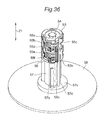
The disc chuck unit 162 is configured to hold a plurality of discs 100 pushed out by the lifter 105, and to separate the held plurality of discs 100 one by one. Specifically, as shown in FIG. 70 and FIG. 71 , the disc chuck unit 162 includes a spindle unit 167, a disc pushing ring 168, and a camshaft unit 169.
The spindle unit 167 includes a spindle shaft 167 a of a substantially cylindrical shape, a spindle head 167 b of a substantially circular truncated cone shape provided the bottom end portion of the spindle shaft 167 a, and a flange 167 c provided at the top end portion of the spindle shaft 167 a.
The spindle shaft 167 a has a helical groove 167 d. The diameter of the spindle shaft 167 a is set to be smaller than the diameter of the center hole 100 a of each disc 100. For example, the diameter of the spindle shaft 167 a is 14.5 mm, and the diameter of the center hole 100 a of the disc 100 is 15 mm.
As shown in FIG. 72 , a plurality of balls 167 e as an example of a disc holding portion is provided near the connection between the spindle shaft 167 a and the spindle head 167 b. In the second embodiment, the three balls 167 e are provided as the disc holding portions. Each ball 167 e is biased outward by an elastic member 167 f such as a spring. The diameter of a circle (circumscribing: not shown) passing the outermost point of each of the three balls 167 e is set to be larger than the diameter of the center hole 100 a of the disc 100. For example, the diameter of the circle passing the outermost point of each of the three balls 167 e is 16.5 mm.
The flange 167 c is attached to the top surface of the shift base 161, allowing the spindle unit 167 to shift integrally with the shift base 161.
The disc pushing ring 168 is provided on the outer circumferential portion of the spindle shaft 167 a. As shown in FIG. 71 , an engaging pin 168 a that engages with a helical groove 167 d is provided on the inner circumferential portion of the disc pushing ring 168. In the second embodiment, three engaging pins 168 a are provided at an interval of 120 degrees.
As shown in FIG. 71 , the camshaft unit 169 includes a substantially cylindrical camshaft 169 a and a cam gear 169 b provided at the top end portion of the camshaft 169 a. The camshaft 169 a is provided with engaging grooves 169 aa extending in the device height direction Z. In First embodiment, the three engaging groove 169 aa are provided at an interval of 120 degrees. The camshaft 169 a is inserted into the spindle shaft 167 a such that the engaging grooves 169 aa engage with the respective engaging pins 168 a of the disc pushing ring 168. As shown in FIG. 68 , the cam gear 169 b meshes with a relay gear 170. As shown in FIG. 69 , the relay gear 170 meshes with a motor gear 171 a press fitted into the drive shaft of a disc chuck motor 171 provided at the shift base 161.
When the disc chuck motor 171 is driven, the drive force of the disc chuck motor 171 is transferred to the camshaft 169 a via the motor gear 171 a, the relay gear 170, and the cam gear 169 b to rotate the camshaft 169 a. When the camshaft 169 a rotates, the disc pushing ring 168 engaging with the engaging grooves 169 aa of the camshaft 169 a rotates. This slides the engaging pins 168 a of the disc pushing ring 168 on the helical groove 167 d, and shifts the disc pushing ring 168 along the outer circumferential face of the spindle shaft 167 a. The disc chuck motor 171 is connected to the control unit of the electric circuit and the power supply 107 and drives under control of the control unit.
When the magazine tray 121 is placed at a prescribed position of the top of the lifter 105 as shown in FIG. 65 , as shown in FIG. 73A and FIG. 73B, the shift base 161 is lowered to the position near the magazine tray 121. Thus, the spindle head 167 b engages with the engaging portion 123 a of the core rod 123 (see FIG. 52B ) provided at the magazine tray 121, whereby the spindle head 167 b and the core rod 123 become coaxial to each other. In this state, the lifter motor 156 is driven and the up-and-down plate 152 rises (see FIG. 67 ).
When the up-and-down plate 152 rises, the up-and-down pins 152 a enter inside the magazine tray 121 through the holes 151 a and 121 e, to push out a plurality of discs 100 from the magazine tray 121. Thus, as shown in FIG. 74 to FIG. 76 , the spindle unit 167 is inserted into the center holes 100 a of the plurality of discs 100, the balls 167 e are pushed onto the inner circumferential portion of the discs 100, and the balls 167 e are shifted to retracted positions on the inner side of the spindle unit 167 against the elastic force of the elastic members 167 f.
After that, the carrier motor 165 is driven to raise the shift base 161. As a result, as shown in FIG. 78 , the balls 167 e contact the inner circumferential portion of the bottommost disc 100 to hold all discs 100. FIG. 79A is a perspective view showing the state where all discs 100 are held by the balls 167 e, and FIG. 79B is a side view showing the state.
When the balls 167 e hold all discs 100, the shift base 161 further rises as being guided by the ball screw 163 and the guide shaft 164. Thus, engagement between the spindle head 167 b and the engaging portion 123 a of the core rod 123 (see FIG. 52B ) is released. Thereafter, the disc chuck motor 171 is driven to rotate the disc pushing ring 168 and lower the disc pushing ring 168 along the outer circumferential face of the spindle shaft 167 a to the top face of the topmost disc 100. After that, as shown in FIG. 80 , the picker 103 is shifted to the front of the device, and the magazine tray 121 recedes from the position near the disc drive 104. Thereafter, under control of the control unit of the electric circuit and the power supply 107, the tray 104 a of the disc drive 104 is ejected as shown in FIG. 81 .
Thereafter, as shown in FIG. 82A and FIG. 82B , the shift base 161 is lowered such that the plurality of disc 100 held by the disc chuck unit 162 are located above the tray 104 a (e.g., immediately above). In this state, the disc chuck motor 171 is driven to rotate the disc pushing ring 168, and as shown in FIG. 83 , to lower the disc pushing ring 168 along the outer circumferential face of the spindle shaft 167 a by the thickness of one disc 100. Due to the lowering of the disc pushing ring 168, the bottommost disc 100 presses the balls 167 e against the elastic force of the elastic members 167 f, passes the sides of the balls 167 e, and are placed on the tray 104 a. When the bottommost disc 100 pass the sides of the balls 167 e, the balls 167 e are slightly pushed out from the outer circumferential face of the spindle shaft 167 a by the elastically restorative force of the elastic members 167 f, and hold the lower edge of the bottommost disc 100. FIG. 84A is a perspective view showing the state where the bottommost disc 100 is placed on the tray 104 a, and FIG. 84B is a side view showing the state.
When the bottommost disc 100 is placed on the tray 104 a, the shift base 161 is raised such that the spindle head 167 b and the tray 104 a are not brought into contact with each other. Thereafter, as shown in FIG. 85 , the tray 104 a is carried into the disc drive 104. Thereafter or simultaneously therewith, the tray 104 a of the disc drive 104 opposing to the disc drive is ejected (not shown). Thereafter, in the manner similarly to that described above, a disc 100 is placed on the tray 104 a, and the tray 104 a is carried into the disc drive 104. Thus, the loading operation as to the disc drives 4 of the bottommost stage (first stage) is completed. This loading operation is repeated as to the second and following stages.
It is to be noted that, the collection of the disc 100 in the disc drive 104 should be performed in the order reverse to the foregoing manner, for example. Specifically, it is performed as follows.
First, the disc chuck motor 171 is driven to rotate the disc pushing ring 168 and raise the disc pushing ring 168 along the outer circumferential face of the spindle shaft 167 a. As a result, the disc chuck unit 162 is ready for holding the collected disc 100. Thereafter, as shown in FIG. 86 , the tray 104 a of the topmost stage disc drive 104 is ejected.
Thereafter, the spindle unit 167 is inserted into the center hole 100 a of the disc 100 on the tray 104 a, the balls 167 e are pressed onto the inner circumferential portion of the disc 100 and shifted to the retracted positions against the elastic force of the elastic members 167 f. When the balls 167 e pass through the center hole 100 a of the disc 100, the elastic members 167 f elastically return and the balls 167 e return to the original protruded positions. When the spindle unit 167 is raised in this state, the balls 167 e contact the inner circumferential portion of the disc 100 to hold the disc 100.
After the shift base 161 rises and the spindle unit 167 is retracted, the tray 104 a from which the disc 100 is collected by the spindle unit 167 is carried into the disc drive 104. Thereafter or simultaneously therewith, the tray 104 a of the disc drive 104 opposing to the disc drive is ejected (not shown). Thereafter, in the manner similarly to that described above, the disc 100 on the tray 104 a is collected by the spindle unit 167, and the tray 104 a is carried into the disc drive 104. Thus, the disc collecting operation as to the disc drives 104 of the topmost stage (first stage) is completed. This disc collecting operation is repeated until the disc 100 in the bottommost stage disc drive 104 is collected. FIG. 87 is a side view showing the state where the spindle unit 167 collects the disc 100 placed on the tray 104 a of the bottommost stage disc drive 104.
When the spindle unit 167 has collected all discs 100, the shift base 161 is raised. Thereafter, the picker 103 shifts to the device-rear side, and the magazine tray 121 is set below the spindle unit 167.
Thereafter, the shift base 161 is lowered, and the spindle head 167 b (see FIG. 71 ) engages with the engaging portion 123 a (see FIG. 2B ) of the core rod 123, whereby the spindle head 167 b and the core rod 123 become coaxial to each other as well as the state shown in FIG. 73A and FIG. 73B .
Thereafter, the pushing ring 168 is lowered and as shown in FIG. 88 , all discs 100 held by the spindle unit 167 are pushed by the pressing force of the pushing ring 168 and stored in the magazine tray 121.
Thereafter, the shift base 161 is raised and, as shown in FIG. 65 , the engagement between the spindle head 167 b and the engaging portion 123 a of the core rod 123 is released.
The magazine tray 121 having stored all discs 100 is returned into the magazine stocker 101 by the picker 103. This conveyance of the magazine tray 121 into the magazine stocker 101 is achieved by, for example, performing the operations that are reverse to the operations having been described with reference to FIG. 56 to FIG. 65 .
With the disc device according to the second embodiment, the magazine tray 121 storing a plurality of discs 100 is conveyed to the position near the disc drive 104. That is, the plurality of discs 100 are simultaneously conveyed to the position near the disc drive 104. Further, with the disc device according to the second embodiment, the plurality of discs 100 in the stacked state are held by the carrier 106, and one disc 100 is separated from the remaining discs 100 above the tray 104 a of each disc drive 104. Thus, as compared to the conventional disc device in which the discs 100 are conveyed from the magazine to the disc drive one by one, the time required for conveying the discs 100 to each of the discs drives 104 can drastically be reduced.
Further, with the disc device according to the second embodiment, since the plurality of disc drives 104 can be used at the same time, it is possible to realize a transmission rate higher than that of the LTO (Linear Tape-Open). For example, a transmission rate of the LTO is currently about 140 MB/S. On the other hand, a transmission rate of an optical disc (BD) is about 4.5 MB/S in the case of single-speed, and about 18 MB/S in the case of quad-speed. With the disc device according to the second embodiment, since twelve disc drives 104 can be used at the same time, it is possible to realize a transmission rate of about 216 MB/S.
Still further, with the disc device according to the second embodiment, the spindle unit 167 is inserted into the center holes 100 a of the plurality of discs 100 to hold the discs 100. This can prevent the plurality of discs 100 from shifting in the plane direction and also prevent the discs 100 from being damaged by contact between the discs and dusts between the discs.
Still further, with the disc device according to the second embodiment, the magazine tray 121 is provided with the core rod 123 that restricts the movement of the plurality of discs 100 in the plane direction. This can further prevent the discs 100 from being damaged by contact between the discs and dusts between the discs.
Still further, with the disc device according to the second embodiment, after the spindle unit 167 engages with the core rod 123, the plurality of discs 100 are pushed from the magazine tray 121 along the core rod 123 and the spindle unit 167 by the lifter 105. This can further prevent the discs 100 from being damaged by contact between the discs and dusts between the discs. Moreover, even when the disc device is placed on an inclined face, the disc 100 can be reliably held by the spindle unit 167 without slipping off.
Still further, with the disc device according to the second embodiment, the up-and-down pins 152 a contact the non-recording and reproducing region of the inner circumferential portion of the disc 100 through the holes 121 e in the magazine tray 121 to push the disc 100. This can prevent the recording and reproducing region of the disc 100 from being damaged.
Still further, with the disc device according to the second embodiment, since the three up-and-down pins 152 a and three holes 121 e are provided, the up-and-down pins 152 a can stably push (rise) the disc 100.
Still further, with the disc device according to the second embodiment, since the lifter 105 and the picker 103 are integrated, only one drive source for shifting them needs to be provided.
<<Third Embodiment>>
Next, a disc device according to a third embodiment of the present disclosure will be described. FIG. 89 is a perspective view of a carrier included in a disc device according to a third embodiment of the present disclosure as seen diagonally from above, and FIG. 90 is an exploded perspective view thereof. The disc device according to the third embodiment is different from the disc device according to the second embodiment in including a carrier 206 in place of the carrier 106. Hereinafter, difference between the carrier 206 and the carrier 106 will be mainly described.
The carrier 206 is configured to hold the plurality of discs pushed out by the lifter 105, to separate one disc from the held discs above the tray 104 a ejected from arbitrary one of drives 104, and to place the separated disc on the tray 104 a.
As shown in FIGS. 89 and 90 , the carrier 206 includes a shift base 261 shifting in the device height direction Z and a disc chuck unit 262 provided at the shift base 261.
As shown in FIGS. 91 and 92 , the shift base 261 includes a bush 261 a connected to a ball screw 163 (see FIG. 68 ) and a guide bearing 261 b connected to a guide shaft 164 (see FIG. 68 ). When the carrier motor 165 (see FIG. 68 ) is driven and the ball screw 163 is rotated, the shift base 261 is guided by the ball screw 163 and the guide shaft 164 and shifts in the device height direction Z. A gear plate 263 is attached to a top face of the shift base 261, the gear plate 263 having a rotation axis and a rotation bearing of various gears, whose description will follow.
The disc chuck unit 262 is configured to hold the plurality of discs 100 pushed out by the lifter 105, and to separate the held plurality of discs 100 one by one. Specifically, as shown in FIGS. 93 and 94 , the disc chuck unit 262 includes separator hooks 264A, 264B, bottom hooks 265A, 265B, a spindle unit 266, and a camshaft unit 267.
Further, as shown in FIG. 49B , in the third embodiment, the recess portion 100 b of disc 100 is formed to have a shape obtained by cutting the top corner portion of the inner circumferential portion of the disc 100 so as to have a level face 100 ba and an inclined face 100 bb. As shown in FIG. 95 , the bottom faces of the claw portions 264Ac, 264Bc of the separator hooks 264A, 264B are each formed to have an inclined face, such that the thickness becomes greater downward from the outer circumferential side to the inner circumferential side. Further, the top faces of the claw portions 264Ac to 265Bc are formed to be perpendicular to the device height direction Z.
As shown in FIGS. 93 and 94 , the spindle unit 266 includes a spindle shaft 266 a of a substantially cylindrical shape, a spindle head 266 b of a substantially circular truncated cone shape provided below the spindle shaft 266 a, and a flange 266 c provided at the top end portion of the spindle shaft 266 a.
By the flange 266 c being directly or indirectly attached to the shift base 261, the spindle unit 266 shifts integrally with the shift base 261. The diameter of the spindle shaft 266 a is set to be smaller than the diameter of the center hole 100 a of each disc 100. For example, the diameter of the spindle shaft 266 a is 14.5 mm, and the diameter of the center hole 100 a of the disc 100 is 15 mm.
As shown in FIG. 96 , the spindle head 266 b is fixed to the bottom end portion of the spindle shaft 266 a by a screw 266 d. Between the spindle head 266 b and the spindle shaft 266 a, four openings 266 e are formed. The claw portions 264Ac to 265Bc of the hooks 264A to 265B are configured so as to be capable of advancing and retracting through the openings 266 e.
As shown in FIG. 97 , the spindle head 266 b is provided with four rotary shaft holes 266 ba. Further, as shown in FIG. 96 , the spindle shaft 266 a is provided with rotary shaft holes 266 aa at the positions corresponding to the positions opposing to the rotary shaft holes 266 ba. The hooks 264A to 265B are rotatably held, by the rotary shafts 264Ac to 265Bc being inserted into corresponding rotary shaft holes 266 aa, 266 ba. Further, the hooks 264A to 265B are held such that the top faces of the claw portions 264Ac, 264Bc of the separator hooks 264A, 264B are positioned higher than the top faces of the claw portions 265Ac, 265Bc of the bottom hooks 265A, 265B by the thickness of approximately one disc. Further, the separator hook 264A and the separator hook 264B are held at the positions being out of phase by 180 degrees from each other in the circumferential direction of the spindle unit 266. The bottom hook 265A and the bottom hook 265B are held at the positions being out of phase by 180 degrees from each other in the circumferential direction of the spindle unit 266.
It is noted that second holding claws that holds the inner circumferential portion of disc 100 is configured with the claw portions 264Ac, 264Bc of the separator hooks 264A, 264B. Further, first holding claws that holds the inner circumferential portion of disc 100 is configured with the claw portions 265Ac, 265Bc of the separator hooks 265A, 265B.
As shown in FIG. 98 , the camshaft unit 267 includes a substantially cylindrical camshaft 267 a, a cam gear 267 b provided at the top end portion of the camshaft 267 a, and cam plates 268A, 268B provided at the bottom end portion of the camshaft 267 a.
At the center portion of the cam gear 267 b, a rotary shaft hole 267 ba is provided. As shown in FIG. 92 , a rotary shaft provided at the shift base 261 is inserted into the rotary shaft hole 267 ba. As shown in FIG. 89 , the cam gear 267 b meshes with a relay gear 270. The relay gear 270 is configured with two gears, for example, and a rotary shaft hole 270 a is provided with the center portion of each gear. As shown in FIG. 92 , a rotary shaft 263 b provided at the gear plate 263 is inserted into rotary shaft hole 270 a. Further, as shown in FIG. 89 or 91 , the relay gear 270 meshes with a motor gear 271 a, into which the drive shaft of the disc chuck motor 271 provided at the shift base 261 is press fitted.
When the disc chuck motor 271 is driven, the drive force of the disc chuck motor 271 is transferred to the camshaft 267 a via the motor gear 271 a, the relay gear 270, and the cam gear 267 b, whereby the camshaft 267 a rotates around the rotary shaft 263 a.
As shown in FIG. 98 , the bottom end portion of the camshaft 267 a is provided with an engaging portion 267 aa for engaging with the cam plate 268A, and an engaging portion 267 ab for engaging with the cam plate 268B. The engaging portions 267 aa, 267 ab are each formed to have a D-shaped cross section.
At the center portion of the cam plate 268A, a D-shaped rotary shaft hole 268Aa is provided. The cam plate 268A is configured so as to be capable of integrally rotating with the camshaft 267 a, by the engaging portion 267 aa of the camshaft 267 a engaging with the rotary shaft hole 268Aa.
At the center portion of the top face of the cam plate 268B, a D-shaped rotary shaft hole 268Ba is provided. The cam plate 268B is configured so as to be capable of integrally rotating with the camshaft 267 a, by the engaging portion 267 ab of the camshaft 267 a engaging with the rotary shaft hole 268Ba.
Further, at the center portion of the bottom face of the cam plate 268B, a rotary shaft 268Bb is provided. As shown in FIG. 93 , the rotary shaft 268Bb is inserted into a rotary shaft bearing 266 ab provided at the bottom end portion of the spindle shaft 266 a. In assembled condition shown FIG. 89 , the rotary shaft hole 268Bb is located coaxially with the rotary shaft 263 a of the gear plate 263.
The top face of the cam plate 268A is provided with a cam groove 268Ab (see FIG. 98 ) along which the drive pin 264Ab of the separator hook 264A slides when the camshaft 267 a rotates. FIGS. 100A to 100D each show the manner of the drive pin 264Ab of the separator hook 264A sliding along the cam groove 268Ab.
The bottom face of the cam plate 268A is provided with a cam groove 268Ac (see FIG. 99 ) along which the drive pin 264Bb of the separator hook 264B slides when the camshaft 267 a rotates. FIGS. 101A to 101D each show the manner of the drive pin 264Bb of the separator hook 264B sliding along the cam groove 268Ac. The cam groove 268Ac has mirror symmetry relative to the cam groove 268Ab, and is provided at the position being out of phase by 180 degrees in the circumferential direction of the spindle unit 266.
The top face of the cam plate 268B is provided with a cam groove 268Bc (see FIG. 98 ) along which the drive pin 265Bb of the bottom hook 265B slides when the camshaft 267 a rotates. FIGS. 102A to 102D each show the manner of the drive pin 265Bb of the bottom hook 265B sliding along the cam groove 268Bc.
The bottom face of the cam plate 268B is provided with a cam groove 268Bd (see FIG. 99 ) along which the drive pin 265Ab of the bottom hook 265A slides when the camshaft 267 a rotates. FIGS. 103A to 103D each show the manner of the drive pin 265Ab of the bottom hook 265A sliding along the cam groove 268Bd. The cam groove 268Bd has mirror symmetry relative to the cam groove 268Bc, and is provided at the position being out of phase by 180 degrees in the circumferential direction of the spindle unit 266.
The separator hook 264A and the separator hook 264B shift such that, in accordance with the rotation of the camshaft 267 a, their respective claw portions 264Ac, 264Bc are located at the position inside the spindle shaft 266 a (see FIGS. 104A and 104B ), the position outside the spindle shaft 266 a (see FIG. 104C ), and the position further outside the spindle shaft 266 a (see FIG. 104D ). It is to be noted that, the separator hooks 264A, 264B are provided with stoppers 264Ad, 264Bd for restricting the rotation range.
The bottom hook 265A and the bottom hook 265B shift such that, in accordance with the rotation of the camshaft 267 a, their respective claw portions 265Ac, 265Bc are located at the position inside the spindle shaft 266 a (see FIGS. 104A and 104D ), the position outside the spindle shaft 266 a (see FIGS. 104B and 104C ). It is to be noted that, the bottom hooks 265A, 265B are provided with stoppers 265Ad, 265Bd for restricting the rotation range.
In the following, the position shown in FIG. 104A where all the hooks 264A to 265B are located inside the spindle shaft 266 a is referred to as the stored position. Further, the position shown in FIG. 104B where only the bottom hooks 265A, 265B are located outside the spindle shaft 266 a is referred to as the holding position. Further, the position shown in FIG. 104C where all the hooks 264A to 265B are located outside the spindle shaft 266 a is referred to as the switching position. Further, the position shown in FIG. 104D where the separator hooks 264A, 264B are located further outside the spindle shaft 266 a and the bottom hooks 265A, 265B are located inside the spindle shaft 266 a is referred to as the separating position.
Next, with reference to FIGS. 105 to 113 , a description will be given of the operation in which the carrier 206 separates one disc from a plurality of discs and places the separated disc on the tray 104 a of the disc drive 104. It is to be noted that, throughout FIGS. 105 to 113 , for the sake of convenience, the claw portions 264Ac, 264Ad of the separator hooks 264A, 264B and the claw portions 265Ac, 265Bc of the bottom hooks 265A, 265B are shown to be on an identical cross section. Further, here, the description is started from the state where the up-and-down pins 152 a push out a plurality of discs 100 from the magazine tray 121.
When the up-and-down pins 152 a push out a plurality of discs 100, as shown in FIG. 105 , the spindle unit 266 is inserted inside the center hole 100 a of a plurality of discs 100. Here, the hooks 264A to 265B are located at the stored position (see FIG. 104A ).
As shown in FIG. 106 , when the up-and-down pins 252 a push the plurality of discs 100 until the claw portions 265Ac, 265Bc of the bottom hooks 265A, 265B are located lower than the bottommost disc among the plurality of discs, the disc chuck motor 271 (see FIG. 91 ) is driven, whereby the camshaft 267 a axially rotates in the normal direction. Thus, as shown in FIG. 107 , the hooks 264A to 265B shift from the stored position (see FIG. 104A ) to the holding position (see FIG. 104B ).
Thereafter, the shift base 261 is raised, and as shown in FIG. 108, the top face of the claw portions 265Ac, 265Bc of the bottom hooks 265A, 265B are brought into contact with the inner circumferential portion of the bottommost disc 100, to hold all the discs 100. Further, at this time, engagement between the spindle head 266 b and the engaging portion 123 a (see FIG. 52B ) of the core rod 123 is released.
Thereafter, the disc chuck motor 271 (see FIG. 91 ) is further driven, whereby the camshaft 267 a further rotates in the normal direction. Thus, the hooks 264A to 265B shift from the holding position (see FIG. 104B ) to the switching position (see FIG. 104C ), and as shown in FIG. 109 , the claw portions 264Ac, 264Bc of the separator hooks 264A, 264B are inserted into the recess portion 100 b of the bottommost disc 100.
Thereafter, the picker 103 shifts to the device-front side, whereby the magazine tray 121 recedes from the position near the disc drive 104 (see FIG. 80 ). Thereafter, the tray 104 a of the disc drive 104 is discharged (see FIG. 81 ).
Thereafter, the shift base 261 is lowered such that the plurality of discs 100 held by the spindle unit 266 is located above the tray 104 a (e.g., immediately above). In this state, the disc chuck motor 271 is further driven, and the camshaft 267 a is rotated further in the normal direction. Thus, the hooks 264A to 265B shift from the switching position (see FIG. 104C ) to the separating position (see FIG. 104D ), and as shown in FIG. 110 , the claw portions 265Ac, 265Bc of the bottom hooks 265A, 265B shift to the position inside the spindle shaft 266 a. As a result, as shown in FIG. 111 , the bottommost disc 100 falls by its self weight, to be placed on the tray 104 a. Further, at this time, the inclined face formed at the bottom face of each of the claw portions 264Ac, 264Bc of the separator hooks 264A, 264B pushes the bottommost disc 100 downward, to function to aid the disc 100 in falling by its self weight. Still further, at this time, the separator hooks 264A, 264B further project outside the spindle shaft 266 a, and the top faces of the claw portions 264Ac, 264Bc of the separator hooks 264A, 264B are brought into contact with the inner circumferential portion of the bottommost disc 100 out of the rest of the disc, and hold the rest of the discs 100.
When the bottommost disc 100 is placed on the tray 104 a, the shift base 261 is raised such that the spindle unit 266 and the tray 104 a are not brought into contact with each other. Thereafter, the tray 104 a is carried into the disc drive 104. Thereafter or simultaneously therewith, the tray 104 a of the disc drive 104 opposing to the handled disc drive is ejected (not shown).
Thereafter, the disc chuck motor 271 is reversely driven, whereby the camshaft 267 a rotates in the reverse direction. Thus, the hooks 264A to 265B shift from the separating position (see FIG. 104D ) to the switching position (see FIG. 104C ), and as shown in FIG. 112 , the claw portions 265Ac, 265Bc of the bottom hooks 265A, 265B shift to the positions outside the spindle shaft 266 a.
Thereafter, the disc chuck motor 271 is further reversely driven, whereby the camshaft 267 a further rotates in the reverse direction. Thus, the hooks 264A to 265B shift from the switching position (see FIG. 104C ) to the holding position (see FIG. 104B ), whereby the claw portions 264Ac, 264Bc of the separators 264A, 264B shift to the positions inside the spindle shaft 266 a as shown in FIG. 113 . As a result, the rest of the discs 100 held by the top face of the claw portions 264Ac, 264Bc of the separator hooks 264A, 264B fall by their self weight, and held by the top face of the claw portions 265Ac, 265Bc of the bottom hooks 265A, 265B.
Thereafter, the disc chuck motor 271 is driven, whereby the camshaft 267 a rotates in the normal direction. Thus, the hooks 264A to 265B shifts from the holding position (see FIG. 104B ) to the switching position (see FIG. 104C ), and as shown in FIG. 109 , the claw portions 264Ac, 264Bc of the separator hooks 264A, 264B are inserted into the recess portion 100 b of the bottommost disc 100.
Thereafter, the shift base 261 is lowered such that the plurality of discs 100 held by the spindle unit 266 is located above (e.g., immediately above) the ejected tray 104 a. In this state, the disc chuck motor 271 is further driven, whereby the camshaft 267 a further shifts in the normal direction. Thus, the hooks 264A to 265B shift from the switching position (see FIG. 104C ) to the separating position (see FIG. 104D ), and as shown in FIG. 110 , the claw portions 265Ac, 265Bc of the bottom hooks 265A, 265B shift to the position inner than the spindle shaft 266 a. As a result, as shown in FIG. 111 , the bottommost disc 100 falls by its self weight, to be placed on the tray 104 a. Further, at this time, the separator hooks 264A, 264B further project outside the spindle shaft 266 a, and the inclined face formed at the bottom face of each of the claw portions 264Ac, 264Bc of the separator hooks 264A, 264B pushes the bottommost disc 100 downward, to function to aid the disc 100 in falling by its self weight. Still further, at this time, the top faces of the claw portions 264Ac, 264Bc of the separator hooks 264A, 264B are brought into contact with the inner circumferential portion of the bottommost disc out of the rest of the discs, and hold the rest of the discs 100.
When the bottommost disc 100 is placed on the tray 104 a, the shift base 261 is raised such that the spindle unit 266 and the tray 104 a are not brought into contact with each other. Thereafter, the tray 104 a is carried into the disc drive 104. Thus, the loading operation as to the disc drives 104 of the bottommost stage (first stage) is completed. This loading operation is repeated as to the second and following stages.
When the loading operation to the topmost-stage disc drives 104 is completed, all the disc drives 104 now accommodate the discs 100, and recording on or reproduction from the discs 100 in the disc drives 104 is enabled.
Next, a description will be given of the operation of the carrier 206 collecting the discs 100 from the disc drives 104.
Firstly, the tray 104 a of the topmost-stage disc drive 104 is ejected.
Thereafter, the shift base 261 is lowered, and the spindle unit 266 is inserted into the center hole 100 a of the disc 100 on the tray 104 a. At this time, the hooks 264A to 265B are at the stored position (see FIG. 104A ).
When the shift base 261 is lowered until the disc 100 is located above the bottom hooks 265A, 265B, the disc chuck motor 271 (see FIG. 91 ) is driven, whereby the camshaft 267 a rotates in the normal direction. Thus, the hooks 264A to 265B shift from the stored position (see FIG. 104A ) to the holding position (see FIG. 104B ).
Thereafter, the shift base 261 is raised, and the top face of the claw portions 265Ac, 265Bc of the bottom hooks 265A, 265B are brought into contact with the inner circumferential portion of the disc 100, to hold the disc 100. Thus, the disc 100 on the tray 104 a is collected.
Thereafter, the tray 104 a from which the disc 100 is collected is carried into the disc drive 104. Thereafter or simultaneously therewith, the tray 104 a of the disc drive 104 opposing to the handled disc drive 104 is ejected.
Thereafter, the shift base 261 is lowered such that the disc held by the spindle unit 266 is located above (e.g., immediately above) the disc 100 on the ejected tray 104 a.
Thereafter, the disc chuck motor 271 (see FIG. 91 ) is reversely driven, and the camshaft 267 a rotates in the reverse direction. Thus, the hooks 264A to 265B shift from the holding position (see FIG. 104B ) to the stored position (see FIG. 104A ). Thus, the disc 100 held by the spindle unit 266 falls by its self weight, and stacked on the disc 100 on the ejected tray 104 a.
Thereafter, the shift base 261 is lowered, and the spindle unit 266 is inserted into the center holes 100 a of the two discs 100 on the ejected tray 104 a.
When the shift base 261 is lowered until the two discs 100 are located above the bottom hooks 265A, 265B, the disc chuck motor 271 (see FIG. 91 ) is driven, whereby the camshaft 267 a rotates in the normal direction. Thus, the hooks 264A to 265B shift from the stored position (see FIG. 104A ) to the holding position (see FIG. 104B ).
Thereafter, the shift base 261 is raised, and the top faces of the claw portions 265Ac, 265Bc of the bottom hooks 265A, 265B are brought into contact with the inner circumferential portion of the bottommost disc 100, to hold all the discs 100.
Thereafter, the tray 104 a from which the disc 100 is collected is carried into the disc drive 104. Thus, the disc collection operation of the disc drives 104 of the topmost stage (first stage) is completed. This disc collection operation is repeated until the discs 100 in the bottommost-stage disc drives 104 are collected.
When the spindle unit 266 has collected all the discs 100, the shift base 261 is raised. Thereafter, the picker 103 shifts to the device-rear side, and the magazine tray 121 is set below the spindle unit 266.
Thereafter, the shift base 261 is lowered, and the spindle head 266 b (see FIG. 71 ) engages with the engaging portion 123 a (see FIG. 52B ) of the core rod 123, whereby the spindle head 266 b and the core rod 123 become coaxial to each other.
Thereafter, the disc chuck motor 271 (see FIG. 91 ) is reversely driven, whereby the camshaft 267 a rotates in the reverse direction. Thus, the hooks 264A to 265B shift from the holding position (see FIG. 104B ) to the stored position (see FIG. 104A ). Thus, all the discs 100 held by the spindle unit 266 fall by their self weight along the spindle head 266 b and the core rod 123, and stored in the magazine tray 121.
Thereafter, the shift base 261 is raised, and the engagement between the tip portion of the spindle head 266 b and the engaging portion 123 a of the core rod 123 is released.
The magazine tray 121 having stored all the discs 100 are returned into the magazine stocker 101 by the picker 103. This conveyance of the magazine tray 121 into the magazine stocker 101 is achieved by, for example, performing the operations that are reverse to the operations having been described with reference to FIGS. 56 to 65 .
With the disc device according to the third embodiment, the plurality of discs 100 in the stacked state are held by the carrier 206, and one disc 100 is separated from the remaining discs 100 above the tray 104 a of each disc drive 104. Thus, as compared to the conventional disc device in which the discs 100 are conveyed from the magazine to the disc drive one by one, the time required for conveying the discs 100 to each of the discs drives 104 can drastically be reduced.
By properly combining arbitrary embodiments of the aforementioned various embodiments, the effects owned by each of them can be made effectual.
Although the present disclosure has been fully described in connection with the preferred embodiments thereof with reference to the accompanying drawings, it is to be noted that various changes and modifications are apparent to those skilled in the art. Such changes and modifications are to be understood as included within the scope of the present disclosure as defined by the appended claims unless they depart therefrom.
The disc device of the present disclosure can suppress an increase both in size of the device and in disc conveying time. Therefore, it is particularly useful for a disc device that conveys a plurality of discs to a plurality of disc drives.
Claims (8)
1. A disc device comprising:
a plurality of magazines each having a tray, each tray storing a plurality of discs;
a disc drive that performs recording or reproducing of information on or from one of the plurality of discs;
a picker that draws out the tray from one of the plurality of magazines and conveys the tray from the one of the plurality of magazines to a position near the disc drive; and
a disc separating and supplying device that, at the position near the disc drive, holds the plurality of discs stored in the tray from the one of the plurality of magazines, separates at least one of the plurality of discs stored in the tray from the one of the plurality of magazines from a remainder of the plurality of discs stored in the tray from the one of the plurality of magazines, and supplies the at least one of the plurality of discs stored in the tray from the one of the plurality of magazines to the disc drive;
wherein the plurality of discs is stored in the tray from the one of the plurality of magazines such that the discs are stacked in close contact to one another.
2. The disc device according to claim 1 , wherein the disc separating and supplying device includes a carrier that holds the plurality of discs in the tray from the one of the plurality of magazines.
3. The disc device according to claim 2 , wherein the carrier includes a disc chuck unit that is inserted into a center hole provided at each of the plurality of discs in the tray from the one of the plurality of magazines, to hold the plurality of discs in the tray from the one of the plurality of magazines.
4. The disc device according to claim 3 , wherein the tray from the one of the plurality of magazines is provided with a core rod that is inserted into a center hole provided at each of the plurality of discs stored in the tray from the one of the plurality of magazines, to restrict shifting of the plurality of discs stored in the tray from the one of the plurality of magazines in a plane direction.
5. The disc device according to claim 4 , wherein:
the disc separating and supplying device further includes a lifter that pushes out the plurality of discs from the tray from the one of the plurality of magazines, and
the lifter is configured to push out the plurality of discs from the tray from the one of the plurality of magazines along the core rod and the disc chuck unit after the disc chuck unit engages with the core rod.
6. The disc device according to claim 4 , wherein:
the tray from the one of the plurality of magazines is provided with at least one hole near the core rod, and
the lifter includes a rod-like member that pushes out the plurality of discs from the tray from the one of the plurality of magazines through the at least one hole.
7. The disc device according to claim 6 , wherein the tray from the one of the plurality of magazines is provided with three holes, and the lifter includes three rod-like members.
8. The disc device according to claim 5 , wherein the lifter and the picker are integrated.
Priority Applications (1)
| Application Number | Priority Date | Filing Date | Title |
|---|---|---|---|
| US14/847,460 US9390747B2 (en) | 2012-03-28 | 2015-09-08 | Disc device |
Applications Claiming Priority (7)
| Application Number | Priority Date | Filing Date | Title |
|---|---|---|---|
| JP2012073434 | 2012-03-28 | ||
| JP2012-073434 | 2012-03-28 | ||
| JP2012126859A JP6008314B2 (en) | 2012-03-28 | 2012-06-04 | Disk unit |
| JP2012-126859 | 2012-06-04 | ||
| PCT/JP2012/006893 WO2013145042A1 (en) | 2012-03-28 | 2012-10-26 | Disc device |
| US14/490,030 US9165592B2 (en) | 2012-03-28 | 2014-09-18 | Disc device |
| US14/847,460 US9390747B2 (en) | 2012-03-28 | 2015-09-08 | Disc device |
Related Parent Applications (1)
| Application Number | Title | Priority Date | Filing Date |
|---|---|---|---|
| US14/490,030 Division US9165592B2 (en) | 2012-03-28 | 2014-09-18 | Disc device |
Publications (2)
| Publication Number | Publication Date |
|---|---|
| US20150380043A1 US20150380043A1 (en) | 2015-12-31 |
| US9390747B2 true US9390747B2 (en) | 2016-07-12 |
Family
ID=49258412
Family Applications (2)
| Application Number | Title | Priority Date | Filing Date |
|---|---|---|---|
| US14/490,030 Active US9165592B2 (en) | 2012-03-28 | 2014-09-18 | Disc device |
| US14/847,460 Active US9390747B2 (en) | 2012-03-28 | 2015-09-08 | Disc device |
Family Applications Before (1)
| Application Number | Title | Priority Date | Filing Date |
|---|---|---|---|
| US14/490,030 Active US9165592B2 (en) | 2012-03-28 | 2014-09-18 | Disc device |
Country Status (5)
| Country | Link |
|---|---|
| US (2) | US9165592B2 (en) |
| EP (1) | EP2833359A4 (en) |
| JP (1) | JP6008314B2 (en) |
| CN (1) | CN104205220B (en) |
| WO (1) | WO2013145042A1 (en) |
Cited By (1)
| Publication number | Priority date | Publication date | Assignee | Title |
|---|---|---|---|---|
| US10327366B2 (en) * | 2015-01-30 | 2019-06-18 | Panasonic Intellectual Property Management Co., Ltd. | Conveyance robot apparatus |
Families Citing this family (12)
| Publication number | Priority date | Publication date | Assignee | Title |
|---|---|---|---|---|
| JP5866626B1 (en) * | 2014-08-05 | 2016-02-17 | パナソニックIpマネジメント株式会社 | Disk device and disk separation method |
| JP6493827B2 (en) | 2014-11-07 | 2019-04-03 | パナソニックIpマネジメント株式会社 | Disk unit |
| JP6583410B2 (en) * | 2015-06-22 | 2019-10-02 | ソニー株式会社 | Disk archive device |
| JP6778895B2 (en) * | 2016-03-17 | 2020-11-04 | パナソニックIpマネジメント株式会社 | Changer device and data library device |
| CN109313914B (en) * | 2016-05-20 | 2021-01-15 | 先锋数码设计制造有限公司 | Disk carrying device and disk carrying method |
| US9959901B1 (en) | 2016-10-12 | 2018-05-01 | Panasonic Intellectual Property Management Co., Ltd. | Inspection method for optical disc |
| JP2018073447A (en) * | 2016-11-04 | 2018-05-10 | パナソニックIpマネジメント株式会社 | Optical disk device, optical disk inspection method, and optical disk inspection program |
| CN110024031B (en) * | 2016-12-02 | 2021-07-20 | 索尼半导体解决方案公司 | Disk storage device and disk filing device |
| WO2018159107A1 (en) | 2017-02-28 | 2018-09-07 | ソニーセミコンダクタソリューションズ株式会社 | Disc storage device and disc archive device |
| CN107578786B (en) * | 2017-08-15 | 2019-06-21 | 北京中科开迪软件有限公司 | A kind of optical disc storage and divide disk device |
| JP7153859B2 (en) * | 2017-12-07 | 2022-10-17 | パナソニックIpマネジメント株式会社 | disk device |
| CN111798877B (en) * | 2019-04-09 | 2022-03-04 | 光宝电子(广州)有限公司 | Disk library storage system and cassette box for the same |
Citations (20)
| Publication number | Priority date | Publication date | Assignee | Title |
|---|---|---|---|---|
| JPS5253712A (en) | 1975-10-30 | 1977-04-30 | Nippon Kokan Kk <Nkk> | Equipment for continuous annealing containingoverage treatment |
| US4055350A (en) | 1975-05-07 | 1977-10-25 | U.S. Philips Corporation | Changer pin for a record changer |
| JPS53144701A (en) | 1977-05-21 | 1978-12-16 | Philips Nv | Record piling spindle for record changer |
| US5416762A (en) | 1991-04-19 | 1995-05-16 | Sony Corporation | Improved disc cartridge and recording and/or reproducing apparatus having means for positioning a turntable and disc cartridge support structure and means for reducing vibrations |
| US5431520A (en) | 1994-04-29 | 1995-07-11 | Eastman Kodak Company | Disc-shaped object storage and retrieval mechanism and method for using same |
| CN1155125A (en) | 1995-09-29 | 1997-07-23 | 国际商业机器公司 | Medium recognition of automatic data base |
| US5793717A (en) | 1995-01-25 | 1998-08-11 | Pioneer Electronic Corporation | Information recording and reproducing apparatus and method of loading/unloading discs |
| US5818723A (en) * | 1994-12-22 | 1998-10-06 | International Business Machines Corporation | Quick access data storage library with backup capability |
| CN1196552A (en) | 1997-04-17 | 1998-10-21 | 阿尔卑斯电气株式会社 | Optical disk discrimination method |
| US6298017B1 (en) | 1995-03-31 | 2001-10-02 | International Business Machines Corp. | Locking method and apparatus for multi-disk cartridge |
| US6370444B1 (en) | 1998-09-30 | 2002-04-09 | Mitsubishi Denki Kabushiki Kaisha | Disc library apparatus |
| JP2005025888A (en) | 2003-07-04 | 2005-01-27 | Nice Tec:Kk | Device and method for transferring disk, and multidisk processor using same |
| JP2005258888A (en) | 2004-03-12 | 2005-09-22 | Nec Corp | Communication network system, communication method therefor, portable terminal and server |
| US7130145B1 (en) | 2003-10-03 | 2006-10-31 | Storage Technology Corporation | Automated storage system for individual and supersets of media |
| JP2008165895A (en) | 2006-12-28 | 2008-07-17 | Hitachi Maxell Ltd | Information storage system |
| JP2008186552A (en) | 2007-01-31 | 2008-08-14 | Hitachi Maxell Ltd | Optical disk, cartridge housing the same, recording/reproducing system, and disk changer |
| US7426055B2 (en) | 2003-08-26 | 2008-09-16 | Leason Holdings Company, L.L.C. | Optical disc supply and interface for digital copier machine |
| US7450331B2 (en) | 2004-12-14 | 2008-11-11 | Spectra Logic Corporation | Variable mobile media storage system |
| WO2009066538A1 (en) | 2007-11-21 | 2009-05-28 | Nec Corporation | Stacking type tray and tray developing mechanism and stacking type tray developing system |
| JP2011204311A (en) | 2010-03-25 | 2011-10-13 | Nippon Hoso Kyokai <Nhk> | Thin optical disk cartridge, thin optical disk conveying device, and thin optical disk recording/reproduction device |
Family Cites Families (3)
| Publication number | Priority date | Publication date | Assignee | Title |
|---|---|---|---|---|
| CN2470916Y (en) * | 2001-03-29 | 2002-01-09 | 任雁胜 | Device for automatic taking and putting disc |
| JP2012073434A (en) | 2010-09-29 | 2012-04-12 | Fujifilm Corp | Adjustment method of stereoscopic display and adjusting device used for the same, and stereoscopic image display method and display unit used for the same |
| JP5717434B2 (en) | 2010-12-17 | 2015-05-13 | 株式会社Adeka | Latent curing agent for masterbatch type epoxy resin and epoxy resin composition using the same |
-
2012
- 2012-06-04 JP JP2012126859A patent/JP6008314B2/en active Active
- 2012-10-26 CN CN201280071812.4A patent/CN104205220B/en active Active
- 2012-10-26 WO PCT/JP2012/006893 patent/WO2013145042A1/en active Application Filing
- 2012-10-26 EP EP12872759.1A patent/EP2833359A4/en not_active Withdrawn
-
2014
- 2014-09-18 US US14/490,030 patent/US9165592B2/en active Active
-
2015
- 2015-09-08 US US14/847,460 patent/US9390747B2/en active Active
Patent Citations (24)
| Publication number | Priority date | Publication date | Assignee | Title |
|---|---|---|---|---|
| US4055350A (en) | 1975-05-07 | 1977-10-25 | U.S. Philips Corporation | Changer pin for a record changer |
| JPS5253712A (en) | 1975-10-30 | 1977-04-30 | Nippon Kokan Kk <Nkk> | Equipment for continuous annealing containingoverage treatment |
| JPS53144701A (en) | 1977-05-21 | 1978-12-16 | Philips Nv | Record piling spindle for record changer |
| US4168069A (en) | 1977-05-21 | 1979-09-18 | U.S. Philips Corporation | Stacking spindle for a phonograph record changer |
| US5416762A (en) | 1991-04-19 | 1995-05-16 | Sony Corporation | Improved disc cartridge and recording and/or reproducing apparatus having means for positioning a turntable and disc cartridge support structure and means for reducing vibrations |
| US5431520A (en) | 1994-04-29 | 1995-07-11 | Eastman Kodak Company | Disc-shaped object storage and retrieval mechanism and method for using same |
| US5818723A (en) * | 1994-12-22 | 1998-10-06 | International Business Machines Corporation | Quick access data storage library with backup capability |
| US5793717A (en) | 1995-01-25 | 1998-08-11 | Pioneer Electronic Corporation | Information recording and reproducing apparatus and method of loading/unloading discs |
| US6298017B1 (en) | 1995-03-31 | 2001-10-02 | International Business Machines Corp. | Locking method and apparatus for multi-disk cartridge |
| CN1155125A (en) | 1995-09-29 | 1997-07-23 | 国际商业机器公司 | Medium recognition of automatic data base |
| US5729464A (en) | 1995-09-29 | 1998-03-17 | International Business Machines Corporation | Media identification in an automated data library |
| CN1196552A (en) | 1997-04-17 | 1998-10-21 | 阿尔卑斯电气株式会社 | Optical disk discrimination method |
| US6130744A (en) | 1997-04-17 | 2000-10-10 | Alps Electric Co., Ltd. | Optical disk discriminating method, including memory storage, for automatic multiple-disk changer |
| US6370444B1 (en) | 1998-09-30 | 2002-04-09 | Mitsubishi Denki Kabushiki Kaisha | Disc library apparatus |
| JP2005025888A (en) | 2003-07-04 | 2005-01-27 | Nice Tec:Kk | Device and method for transferring disk, and multidisk processor using same |
| US7426055B2 (en) | 2003-08-26 | 2008-09-16 | Leason Holdings Company, L.L.C. | Optical disc supply and interface for digital copier machine |
| US7130145B1 (en) | 2003-10-03 | 2006-10-31 | Storage Technology Corporation | Automated storage system for individual and supersets of media |
| JP2005258888A (en) | 2004-03-12 | 2005-09-22 | Nec Corp | Communication network system, communication method therefor, portable terminal and server |
| US7450331B2 (en) | 2004-12-14 | 2008-11-11 | Spectra Logic Corporation | Variable mobile media storage system |
| JP2008165895A (en) | 2006-12-28 | 2008-07-17 | Hitachi Maxell Ltd | Information storage system |
| JP2008186552A (en) | 2007-01-31 | 2008-08-14 | Hitachi Maxell Ltd | Optical disk, cartridge housing the same, recording/reproducing system, and disk changer |
| WO2009066538A1 (en) | 2007-11-21 | 2009-05-28 | Nec Corporation | Stacking type tray and tray developing mechanism and stacking type tray developing system |
| US20100288661A1 (en) | 2007-11-21 | 2010-11-18 | Kenji Tagami | Stacking type tray and tray developing mechanism and stacking type tray developing system |
| JP2011204311A (en) | 2010-03-25 | 2011-10-13 | Nippon Hoso Kyokai <Nhk> | Thin optical disk cartridge, thin optical disk conveying device, and thin optical disk recording/reproduction device |
Non-Patent Citations (4)
| Title |
|---|
| Extended European Search Report issued Feb. 12, 2016 in corresponding European Application No. 12872759.1. |
| First Office Action issued Dec. 14, 2015 in corresponding Chinese Application No. 201280071812.4 (with English translation). |
| International Preliminary Report on Patentability and Written Opinion of the International Searching Authority issued Oct. 9, 2014 in International (PCT) Application No. PCT/JP2012/006893. |
| International Search Report issued Jan. 15, 2013 in International (PCT) Application No. PCT/JP2012/006893. |
Cited By (1)
| Publication number | Priority date | Publication date | Assignee | Title |
|---|---|---|---|---|
| US10327366B2 (en) * | 2015-01-30 | 2019-06-18 | Panasonic Intellectual Property Management Co., Ltd. | Conveyance robot apparatus |
Also Published As
| Publication number | Publication date |
|---|---|
| US20150380043A1 (en) | 2015-12-31 |
| EP2833359A4 (en) | 2016-03-16 |
| JP2013229087A (en) | 2013-11-07 |
| US9165592B2 (en) | 2015-10-20 |
| JP6008314B2 (en) | 2016-10-19 |
| CN104205220A (en) | 2014-12-10 |
| US20150074692A1 (en) | 2015-03-12 |
| WO2013145042A1 (en) | 2013-10-03 |
| EP2833359A1 (en) | 2015-02-04 |
| CN104205220B (en) | 2016-11-09 |
Similar Documents
| Publication | Publication Date | Title |
|---|---|---|
| US9390747B2 (en) | Disc device | |
| US8843946B2 (en) | Disc device with carrier for retaining plurality of stacked discs | |
| US8881184B2 (en) | Disc device | |
| US8863160B2 (en) | Disc device having a carrier for retaining a plurality of discs in a stacked state | |
| US9123379B2 (en) | Disk | |
| US9761265B2 (en) | Disc device and disc separation method | |
| US8873356B2 (en) | Disc device having a picker for conveying a pluralty of discs in a stacked state | |
| US6370105B1 (en) | Recording media accommodating apparatus including a playback mechanism that transfers media | |
| US6005744A (en) | Storage device for storing magazines of recordable media | |
| US9058848B2 (en) | Disc library device | |
| WO2012041760A1 (en) | Cell engagement and retention carriage | |
| JP5884033B2 (en) | Disk device and spindle unit | |
| EP1335359A1 (en) | Recording and/or reproducing device for disk | |
| US20100172221A1 (en) | Disc cartridge, and disc changer | |
| JP2014032732A (en) | Insertion and extraction device | |
| JP2021028856A (en) | Disk tray and disk device | |
| JP6064442B2 (en) | Optical disk device | |
| JPH0278053A (en) | Cassette automatic exchanger for memory disk | |
| JP2016164821A (en) | Optical disk device |
Legal Events
| Date | Code | Title | Description |
|---|---|---|---|
| STCF | Information on status: patent grant |
Free format text: PATENTED CASE |
|
| MAFP | Maintenance fee payment |
Free format text: PAYMENT OF MAINTENANCE FEE, 4TH YEAR, LARGE ENTITY (ORIGINAL EVENT CODE: M1551); ENTITY STATUS OF PATENT OWNER: LARGE ENTITY Year of fee payment: 4 |
|
| FEPP | Fee payment procedure |
Free format text: MAINTENANCE FEE REMINDER MAILED (ORIGINAL EVENT CODE: REM.); ENTITY STATUS OF PATENT OWNER: LARGE ENTITY |