US9395480B2 - Antistatic light guide plate and method for fabricating the same - Google Patents

Antistatic light guide plate and method for fabricating the same Download PDF

Info

Publication number
US9395480B2
US9395480B2 US14/361,022 US201314361022A US9395480B2 US 9395480 B2 US9395480 B2 US 9395480B2 US 201314361022 A US201314361022 A US 201314361022A US 9395480 B2 US9395480 B2 US 9395480B2
Authority
US
United States
Prior art keywords
lgp
electro
conductive
macromolecular compound
organic macromolecular
Prior art date
Legal status (The legal status is an assumption and is not a legal conclusion. Google has not performed a legal analysis and makes no representation as to the accuracy of the status listed.)
Active, expires
Application number
US14/361,022
Other versions
US20150234115A1 (en
Inventor
Wulijibaier Tang
Xin Gai
Current Assignee (The listed assignees may be inaccurate. Google has not performed a legal analysis and makes no representation or warranty as to the accuracy of the list.)
BOE Technology Group Co Ltd
Beijing BOE Display Technology Co Ltd
Original Assignee
BOE Technology Group Co Ltd
Priority date (The priority date is an assumption and is not a legal conclusion. Google has not performed a legal analysis and makes no representation as to the accuracy of the date listed.)
Filing date
Publication date
Application filed by BOE Technology Group Co Ltd filed Critical BOE Technology Group Co Ltd
Assigned to BEIJING BOE DISPLAY TECHNOLOGY CO., LTD., BOE TECHNOLOGY GROUP CO., LTD. reassignment BEIJING BOE DISPLAY TECHNOLOGY CO., LTD. ASSIGNMENT OF ASSIGNORS INTEREST (SEE DOCUMENT FOR DETAILS). Assignors: GAI, Xin, Tang, Wulijibaier
Publication of US20150234115A1 publication Critical patent/US20150234115A1/en
Application granted granted Critical
Publication of US9395480B2 publication Critical patent/US9395480B2/en
Active legal-status Critical Current
Adjusted expiration legal-status Critical

Links

Images

Classifications

    • GPHYSICS
    • G02OPTICS
    • G02BOPTICAL ELEMENTS, SYSTEMS OR APPARATUS
    • G02B6/00Light guides; Structural details of arrangements comprising light guides and other optical elements, e.g. couplings
    • G02B6/0001Light guides; Structural details of arrangements comprising light guides and other optical elements, e.g. couplings specially adapted for lighting devices or systems
    • G02B6/0011Light guides; Structural details of arrangements comprising light guides and other optical elements, e.g. couplings specially adapted for lighting devices or systems the light guides being planar or of plate-like form
    • G02B6/0065Manufacturing aspects; Material aspects
    • CCHEMISTRY; METALLURGY
    • C08ORGANIC MACROMOLECULAR COMPOUNDS; THEIR PREPARATION OR CHEMICAL WORKING-UP; COMPOSITIONS BASED THEREON
    • C08JWORKING-UP; GENERAL PROCESSES OF COMPOUNDING; AFTER-TREATMENT NOT COVERED BY SUBCLASSES C08B, C08C, C08F, C08G or C08H
    • C08J5/00Manufacture of articles or shaped materials containing macromolecular substances
    • C08J5/18Manufacture of films or sheets
    • GPHYSICS
    • G02OPTICS
    • G02BOPTICAL ELEMENTS, SYSTEMS OR APPARATUS
    • G02B6/00Light guides; Structural details of arrangements comprising light guides and other optical elements, e.g. couplings
    • G02B6/0001Light guides; Structural details of arrangements comprising light guides and other optical elements, e.g. couplings specially adapted for lighting devices or systems
    • G02B6/0011Light guides; Structural details of arrangements comprising light guides and other optical elements, e.g. couplings specially adapted for lighting devices or systems the light guides being planar or of plate-like form
    • G02B6/0081Mechanical or electrical aspects of the light guide and light source in the lighting device peculiar to the adaptation to planar light guides, e.g. concerning packaging
    • G02B6/0093Means for protecting the light guide
    • CCHEMISTRY; METALLURGY
    • C08ORGANIC MACROMOLECULAR COMPOUNDS; THEIR PREPARATION OR CHEMICAL WORKING-UP; COMPOSITIONS BASED THEREON
    • C08JWORKING-UP; GENERAL PROCESSES OF COMPOUNDING; AFTER-TREATMENT NOT COVERED BY SUBCLASSES C08B, C08C, C08F, C08G or C08H
    • C08J2300/00Characterised by the use of unspecified polymers
    • C08J2300/12Polymers characterised by physical features, e.g. anisotropy, viscosity or electrical conductivity
    • GPHYSICS
    • G02OPTICS
    • G02FOPTICAL DEVICES OR ARRANGEMENTS FOR THE CONTROL OF LIGHT BY MODIFICATION OF THE OPTICAL PROPERTIES OF THE MEDIA OF THE ELEMENTS INVOLVED THEREIN; NON-LINEAR OPTICS; FREQUENCY-CHANGING OF LIGHT; OPTICAL LOGIC ELEMENTS; OPTICAL ANALOGUE/DIGITAL CONVERTERS
    • G02F1/00Devices or arrangements for the control of the intensity, colour, phase, polarisation or direction of light arriving from an independent light source, e.g. switching, gating or modulating; Non-linear optics
    • G02F1/01Devices or arrangements for the control of the intensity, colour, phase, polarisation or direction of light arriving from an independent light source, e.g. switching, gating or modulating; Non-linear optics for the control of the intensity, phase, polarisation or colour 
    • G02F1/13Devices or arrangements for the control of the intensity, colour, phase, polarisation or direction of light arriving from an independent light source, e.g. switching, gating or modulating; Non-linear optics for the control of the intensity, phase, polarisation or colour  based on liquid crystals, e.g. single liquid crystal display cells
    • G02F1/133Constructional arrangements; Operation of liquid crystal cells; Circuit arrangements
    • G02F1/1333Constructional arrangements; Manufacturing methods
    • G02F1/1335Structural association of cells with optical devices, e.g. polarisers or reflectors
    • G02F1/1336Illuminating devices
    • G02F1/133615Edge-illuminating devices, i.e. illuminating from the side
    • GPHYSICS
    • G02OPTICS
    • G02FOPTICAL DEVICES OR ARRANGEMENTS FOR THE CONTROL OF LIGHT BY MODIFICATION OF THE OPTICAL PROPERTIES OF THE MEDIA OF THE ELEMENTS INVOLVED THEREIN; NON-LINEAR OPTICS; FREQUENCY-CHANGING OF LIGHT; OPTICAL LOGIC ELEMENTS; OPTICAL ANALOGUE/DIGITAL CONVERTERS
    • G02F2202/00Materials and properties
    • G02F2202/22Antistatic materials or arrangements

Definitions

  • a first aspect of the invention provides a LGP, the LGP is electro-conductive.
  • a fluorescent powder layer is coated on one or more surfaces of the LGP.
  • the method further comprises the following step: attaching a side adhesive tape to at least one side surface of the LGP.
  • the method further comprises the following step: attaching a side adhesive tape to at least one side surface of the LGP.
  • FIG. 3 schematically illustrates a cross section of the antistatic LGP provided in at least one of Embodiments 1 to 3 taking along line A-A of FIGS. 1 and 2 ;
  • FIG. 4 is a flow chart of fabricating an antistatic LGP provided by Embodiment 1 of the invention.
  • FIG. 5 is a flow chart of fabricating an antistatic LGP provided by Embodiment 2 of the invention.
  • S 1 preparing an electro-conductive solution; the electro-conductive solution is obtained by dissolving an electro-conductive organic macromolecular compound and ink in an acidic solution, or by dissolving an electro-conductive organic macromolecular compound in an acidic solution;
  • An antistatic LGP provided by the embodiment is electro-conductive.
  • An electro-conductive film made of an electro-conductive organic macromolecular compound is disposed on one or more surfaces of the antistatic LGP provided by the embodiment.
  • the electro-conductive organic macromolecular compound is polyaniline or polythiophene.
  • an electro-conductive adhesive tape 3 is disposed on a side surface 2 of the antistatic LGP 1 , as illustrated in FIGS. 1 and 2 .
  • the side adhesive tape 3 comprises an electro-conductive layer 4 and a reflective layer 5 , and the reflective layer 5 is directly attached to the side surface 2 of the antistatic LGP 1 as illustrated in FIG. 3 .
  • the method further comprises the following step:
  • an electro-conductive film is disposed on one or more surfaces of the antistatic LGP in at least one embodiment of the invention; alternatively, the antistatic LGP is made of an electro-conductive organic macromolecular compound, or made of the material comprising an electro-conductive organic macromolecular compound, making the antistatic LGP electro-conductive, therefore the electrostatic charges can be effectively released.
  • the antistatic LGP can release the electrostatic charges in a better way.

Abstract

A light guide plate (LGP) and a method for fabricating the same are disclosed, the LGP is electro-conductive. The fabrication method including the following steps: preparing an electro-conductive solution; making one or more surfaces of a regular LGP adsorb the electro-conductive solution uniformly; drying the LGP which adsorbs the electro-conductive solution to form an electro-conductive film on the one or more surfaces. A method for fabricating the LGP is also disclosed in which electro-conductive organic macromolecular compound is used as a raw material. The effect of static charge on the LGP is avoided by the electro-conductive property of the LGP.

Description

FIELD OF THE ART
Embodiments of the invention relate to the field of liquid crystal display technologies, more particularly, to an antistatic light guide plate (LGP) and a method for fabricating the same.
BACKGROUND
After conducting performance test on a liquid crystal display (LCD) module, a LGP of the LCD module often has some defects such as white dots and/or scratch caused by foreign objects. The foreign objects are usually adsorbed onto the LGP by electrostatic charges. The above defects can be prevented if the electrostatic charges on the LGP can be effectively released.
SUMMARY
The disclosure provides an antistatic LGP and a method for fabricating the same.
A first aspect of the invention provides a LGP, the LGP is electro-conductive.
For example, an electro-conductive film made of an electro-conductive organic macromolecular compound is disposed on one or more surfaces of the LGP.
For example, the electro-conductive organic macromolecular compound is polyaniline or polythiophene.
For example, a material of the LGP is an electro-conductive organic macromolecular compound, or a material of the LGP comprises an electro-conductive organic macromolecular compound.
For example, the electro-conductive organic macromolecular compound is polyaniline or polythiophene.
For example, a fluorescent powder layer is coated on one or more surfaces of the LGP.
For example, it further comprises a side adhesive tape disposed on at least one side surface of the LGP.
For example, the side adhesive tape comprises an electro-conductive layer and a reflective layer, and the reflective layer is attached to the at least one side surface of the LGP.
A second aspect of the disclosure provides a method for fabricating an antistatic LGP, the method comprises the steps of:
preparing an electro-conductive solution;
making one or more surfaces of a regular LGP adsorb the electro-conductive solution uniformly; and
drying the LGP that adsorbed the electro-conductive solution to form an electro-conductive film on the one or more surfaces of the LGP.
For example, the step of preparing the electro-conductive solution comprises: dissolving an electro-conductive organic macromolecular compound and ink in an acidic solution, or by dissolving an electro-conductive organic macromolecular compound in an acidic solution; the step of making one or more surfaces of a regular LGP adsorb the electro-conductive solution uniformly comprises: cleansing and then soaking the regular LGP in the electro-conductive solution.
For example, the step of preparing the electro-conductive solution comprises: dissolving an electro-conductive organic macromolecular compound and ink in an acidic solution; the step of making one or more surfaces of a regular LGP adsorb the electro-conductive solution uniformly comprises: spraying the electro-conductive solution onto one or more surfaces of the regular LGP after cleansing the regular LGP.
For example, the method further comprises the following step: attaching a side adhesive tape to at least one side surface of the LGP.
A third aspect of the disclosure provides a method for fabricating a LGP, the method comprises steps of:
providing an electro-conductive organic macromolecular compound or a mixture of an electro-conductive organic macromolecular compound and polymethylmethacrylate as a raw material and plasticizing the raw material;
filling the plasticized material into a mold;
pressure-holding the mold filled with the material; and
cooling the pressure-held mold.
For example, the method further comprises the following step: attaching a side adhesive tape to at least one side surface of the LGP.
BRIEF DESCRIPTION OF THE DRAWINGS
In order to clearly illustrate the technical solution of the embodiments of the invention, the drawings of the embodiments will be briefly described in the following. It is obvious that the described drawings are only related to some embodiments of the invention and thus are not limitative of the invention.
FIG. 1 schematically illustrates a diagram of attaching a side adhesive tape to a side surface of an antistatic LGP provided in at least one of Embodiments 1 to 3 of the invention;
FIG. 2 schematically illustrates diagram after attaching a side adhesive tape to a side surface of an antistatic LGP provided in at least one of Embodiments 1 to 3 of the invention;
FIG. 3 schematically illustrates a cross section of the antistatic LGP provided in at least one of Embodiments 1 to 3 taking along line A-A of FIGS. 1 and 2;
FIG. 4 is a flow chart of fabricating an antistatic LGP provided by Embodiment 1 of the invention;
FIG. 5 is a flow chart of fabricating an antistatic LGP provided by Embodiment 2 of the invention;
FIG. 6 is a flow chart of fabricating an antistatic LGP provided by Embodiment 3 of the invention.
1-antistatic LGP; 2-side surface; 3-adhesive tape; 4-condutive layer; 5-reflective layer.
DETAILED DESCRIPTION
In order to make objects, technical details and advantages of the embodiments of the invention apparent, the technical solutions of the embodiment will be described in a clearly and fully understandable way in connection with the drawings related to the embodiments of the invention. It is obvious that the described embodiments are just a part but not all of the embodiments of the invention. Based on the described embodiments herein, those skilled in the art can obtain other embodiment(s), without any inventive work, which should be within the scope of the invention.
Embodiment 1
An antistatic LGP provided by the embodiment of the invention is electro-conductive. An electro-conductive film made of an electro-conductive organic macromolecular compound is disposed on one or more surfaces of the antistatic LGP provided by the embodiment. In the embodiment, the electro-conductive organic macromolecular compound is polyaniline or polythiophene. For example, to make the antistatic LGP release the electrostatic charges in a better way, an electro-conductive adhesive tape 3 is disposed on a side surface 2 of the antistatic LGP 1, as illustrated in FIGS. 1 and 2. The side adhesive tape 3 comprises an electro-conductive layer 4 and a reflective layer 5, and the reflective layer 5 is attached to the side surface 2 of the antistatic LGP 1 as illustrated in FIG. 3. Herein, the electro-conductive layer 4 is used to release the electrostatic charges generated on surfaces of the LGP; the reflective layer 5 is mainly used to reflect light exiting the side surface of the LGP back to the interior of the LGP. Generally, most of the electrostatic charges generated on the LGP are distributed on its edges, thus, the electrostatic charges on the surfaces of the LGP are released into the environment via the electro-conductive tape. Therefore, the side adhesive tape comprising the dual layer structure acts as a conductor. Furthermore, in other embodiments of the invention, the side adhesive tape 3 may also be disposed on the remaining side surfaces of the LGP 1 of FIG. 1, except for the side surface having a backlight; for example, the side adhesive tape 3 is disposed on at least one side surface, which can achieve the above effect in the same way.
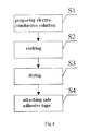
As illustrated in FIG. 4, a method for fabricating the antistatic LGP provided by the embodiment comprises the following steps:
S1: preparing an electro-conductive solution; the electro-conductive solution is obtained by dissolving an electro-conductive organic macromolecular compound and ink in an acidic solution, or by dissolving an electro-conductive organic macromolecular compound in an acidic solution;
S2: cleansing and then soaking a regular LGP in the electro-conductive solution and making one or more surfaces of the regular LGP adsorb the electro-conductive solution uniformly;
S3: drying the LGP adsorbing the electro-conductive solution to form an electro-conductive film on the one or more surfaces of the LGP, thereby obtaining an antistatic LGP.
For example, as illustrated in FIGS. 1 and 2, the method further comprises the following step:
S4: attaching an electro-conductive adhesive tape 3 to a side surface 2 of the antistatic LGP 1.
In the embodiment, the electro-conductive organic macromolecular compound in step S1 is polyaniline or polythiophene.
When being used, by contacting a locating post (not shown) of the antistatic LGP with an electro-conductive back cover (not shown), the electrostatic charges on the antistatic LGP can be released, preventing the electrostatic charges from adsorbing foreign objects.
Embodiment 2
An antistatic LGP provided by the embodiment is electro-conductive. An electro-conductive film made of an electro-conductive organic macromolecular compound is disposed on one or more surfaces of the antistatic LGP provided by the embodiment. In the embodiment, the electro-conductive organic macromolecular compound is polyaniline or polythiophene. For example, to make the antistatic LGP release the electrostatic charges in a better way, an electro-conductive adhesive tape 3 is disposed on a side surface 2 of the antistatic LGP 1, as illustrated in FIGS. 1 and 2. The side adhesive tape 3 comprises an electro-conductive layer 4 and a reflective layer 5, and the reflective layer 5 is directly attached to the side surface 2 of the antistatic LGP 1 as illustrated in FIG. 3.
As illustrated in FIG. 5, a method for fabricating the antistatic LGP provided by the embodiment comprises the following steps:
S10: preparing an electro-conductive solution; the electro-conductive solution is obtained by dissolving an electro-conductive organic macromolecular compound and ink in an acidic solution; wherein the ink is added to make the electro-conductive organic macromolecular compound in the electro-conductive solution adsorb onto the surfaces of the LGP more easily;
S20: spraying the electro-conductive solution onto one or more surfaces of a cleansed regular LGP and making the surface of the regular LGP adsorb the electro-conductive solution uniformly;
S30: drying the LGP adsorbing the electro-conductive solution to form an electro-conductive film on the one or more surfaces of the LGP, thereby obtaining an antistatic LGP.
For example, as illustrated in FIGS. 1 and 2, the method further comprises the following step:
S40: attaching an electro-conductive adhesive tape 3 to a side surface 2 of the antistatic LGP 1.
In the embodiment, the electro-conductive organic macromolecular compound in step S10 is polyaniline or polythiophene.
When being used, by contacting a locating post (not shown) of the antistatic LGP with an electro-conductive back cover (not shown), the electrostatic charges on the antistatic LGP can be released, preventing the electrostatic charges from adsorbing foreign objects.
Embodiment 3
An antistatic LGP provided by the embodiment is electro-conductive. A material of the antistatic LGP provided by the embodiment is an electro-conductive organic macromolecular compound, or its material comprises an electro-conductive organic macromolecular compound, making the antistatic LGP electro-conductive. In the embodiment, the electro-conductive organic macromolecular compound is at least one of polyaniline and polythiophene.
The color of polyaniline in solid state is green, and the color of polythiophene in solid state is red. The light-transmittance of both polyaniline and polythiophene is close to that of polymethylmethacrylate (PMMA). If polyaniline, or a mixture of polyaniline and PMMA is used as the raw material, the fabricated antistatic LGP appears as green. If polythiophene, or a mixture of polythiophene and PMMA is used as the raw material, the fabricated antistatic LGP appears as red. If a mixture of polyaniline, polythiophene and PMMA is used as the raw material, the fabricated antistatic LGP has a hybrid color of red and green. When white light passes through a green antistatic LGP, the green antistatic LGP turns the light from white to green. When white light passes through a red antistatic LGP, the red antistatic LGP turns the light from white to red. When white light passes through a hybrid green-red antistatic LGP, the hybrid green-red antistatic LGP turns the light from white to hybrid green-red. To prevent white light passing through the antistatic LGP from changing its color, a fluorescent powder layer is coated on one or more surfaces of the antistatic LGP. The fluorescent powder layer transform the green, red or hybrid green-red light back to white again.
For example, to make the antistatic LGP release the electrostatic charges in a better way, an electro-conductive adhesive tape 3 is disposed on a side surface 2 of the antistatic LGP 1, as illustrated in FIGS. 1 and 2. The side adhesive tape 3 comprises an electro-conductive layer 4 and a reflective layer 5, and the reflective layer 5 is directly attached to the side surface 2 of the antistatic LGP 1 as illustrated in FIG. 3.
As illustrated in FIG. 6, a method for fabricating the antistatic LGP provided by the embodiment comprises the following steps:
S100: providing an electro-conductive organic macromolecular compound or a mixture of an electro-conductive organic macromolecular compound and PMMA as a raw material and plasticizing the raw material;
S200: filling the plasticized material into a mold;
S300: pressure-holding the mold filled with the material; and
S400: cooling the pressure-held mold to obtain an antistatic LGP.
In the embodiment, the electro-conductive organic macromolecular compound in step S100 is polyaniline or polythiophene.
For example, the method further comprises the following step:
S500: coating a fluorescent powder layer on the one or more surfaces of the LOP.
For example, as illustrated in FIGS. 1 and 2, the method further comprises the following step:
S600: attaching an electro-conductive adhesive tape 3 to a side surface 2 of the antistatic LGP 1.
When being used, by contacting a locating post (not shown) of the antistatic LGP with an electro-conductive back cover (not shown), the electrostatic charges on the antistatic LGP can be released, preventing the electrostatic charges from adsorbing foreign objects.
In summary, an electro-conductive film is disposed on one or more surfaces of the antistatic LGP in at least one embodiment of the invention; alternatively, the antistatic LGP is made of an electro-conductive organic macromolecular compound, or made of the material comprising an electro-conductive organic macromolecular compound, making the antistatic LGP electro-conductive, therefore the electrostatic charges can be effectively released. By attaching an electro-conductive adhesive tape on a side surface of the antistatic LGP, the antistatic LGP can release the electrostatic charges in a better way.
What are described above is related to the illustrative embodiments of the disclosure only and not limitative to the scope of the disclosure; the scopes of the disclosure are defined by the accompanying claims.

Claims (16)

What is claimed is:
1. A light guide plate (LGP), comprising an electro-conductive and a side adhesive tape disposed on at least one side surface of the LGP, wherein the side adhesive tape comprises:
a reflective layer with a first surface of the reflective layer being attached to the at least one side surface of the LGP; and
an electro-conductive layer to release electrostatic charges generated on surfaces of the LGP, the electro-conductive layer being attached to a second surface of the reflective layer that is opposite to the first surface of the reflective layer.
2. The LGP of claim 1, wherein an electro-conductive film made of an electro-conductive organic macromolecular compound is disposed on one or more surfaces of the LGP.
3. The LGP of claim 2, wherein the electro-conductive organic macromolecular compound is polyaniline or polythiophene.
4. The LGP of claim 1, wherein a material of the LGP is an electro-conductive organic macromolecular compound, or a material of the LGP comprises an electro-conductive organic macromolecular compound.
5. The LGP of claim 4, wherein the electro-conductive organic macromolecular compound is at least one of polyaniline and polythiophene.
6. The LGP of claim 4, wherein a fluorescent powder layer is coated on one or more surfaces of the LGP.
7. A method for fabricating a LGP, comprising steps of:
preparing an electro-conductive solution;
making one or more surfaces of a regular LGP adsorb the electro-conductive solution uniformly; and
drying the LGP that adsorbed the electro-conductive solution, to form an electro-conductive film on the one or more surfaces thereof, wherein:
the step of preparing the electro-conductive solution comprises: dissolving an electro-conductive organic macromolecular compound and ink in an acidic solution, or dissolving an electro-conductive organic macromolecular compound in an acidic solution;
the step of making one or more surfaces of a regular LGP adsorb the electro-conductive solution uniformly comprises: cleansing and then soaking the LGP in the electro-conductive solution.
8. The method of claim 7, wherein,
the step of making one or more surfaces of a regular LGP adsorb the electro-conductive solution uniformly comprises: spraying the electro-conductive solution onto one or more surfaces of a cleansed regular LGP.
9. The method of claim 7, wherein the electro-conductive organic macromolecular compound is polyaniline or polythiophene.
10. The method of claim 7, further comprising a step of: attaching a side adhesive tape to at least one side surface of the LGP.
11. The method of claim 10, wherein the side adhesive tape comprises an electro-conductive layer and a reflective layer, and the reflective layer is attached to the at least one side surface of the LGP.
12. A method for fabricating a LGP, comprising steps of:
providing an electro-conductive organic macromolecular compound or a mixture of an electro-conductive organic macromolecular compound and polymethylmethacrylate as a raw material and plasticizing the raw material;
filling the plasticized material into a mold;
pressure-holding the mold filled with the material; and
cooling the pressure-held mold.
13. The method of claim 12, wherein the electro-conductive organic macromolecular compound is at least one of polyaniline and polythiophene.
14. The method of claim 12, further comprising a step of: coating a fluorescent powder layer on one or more surfaces of the LGP.
15. The method of claim 12, further comprising a step of: attaching a side adhesive tape to at least one side surface of the LGP.
16. The method of claim 15, wherein the side adhesive tape comprises an electro-conductive layer and a reflective layer, and the reflective layer is attached to the at least one side surface of the LGP.
US14/361,022 2013-02-07 2013-04-12 Antistatic light guide plate and method for fabricating the same Active 2033-07-03 US9395480B2 (en)

Applications Claiming Priority (4)

Application Number Priority Date Filing Date Title
CN201310049532.X 2013-02-07
CN201310049532XA CN103091768A (en) 2013-02-07 2013-02-07 Anti-static light guide plate and prepared method thereof
CN201310049532 2013-02-07
PCT/CN2013/074144 WO2014121556A1 (en) 2013-02-07 2013-04-12 Antistatic light guide plate and fabrication method therefor

Publications (2)

Publication Number Publication Date
US20150234115A1 US20150234115A1 (en) 2015-08-20
US9395480B2 true US9395480B2 (en) 2016-07-19

Family

ID=48204560

Family Applications (1)

Application Number Title Priority Date Filing Date
US14/361,022 Active 2033-07-03 US9395480B2 (en) 2013-02-07 2013-04-12 Antistatic light guide plate and method for fabricating the same

Country Status (3)

Country Link
US (1) US9395480B2 (en)
CN (1) CN103091768A (en)
WO (1) WO2014121556A1 (en)

Cited By (1)

* Cited by examiner, † Cited by third party
Publication number Priority date Publication date Assignee Title
US11244639B2 (en) * 2019-01-21 2022-02-08 Fuzhou Boe Optoelectronics Technology Co., Ltd. Display panel and driving method thereof, and display system

Families Citing this family (3)

* Cited by examiner, † Cited by third party
Publication number Priority date Publication date Assignee Title
CN105807362B (en) * 2016-06-01 2018-12-11 京东方科技集团股份有限公司 Light guide plate and preparation method thereof, backlight module and display device
CN112714538A (en) * 2020-12-23 2021-04-27 常州欣战江特种纤维有限公司 Method suitable for electrostatic weakening of chemical fiber control upper computer
CN115090477A (en) * 2022-08-05 2022-09-23 安徽艾雅伦新材料科技有限公司 Anti-static film coating equipment and film coating method for PVC (polyvinyl chloride) plate

Citations (12)

* Cited by examiner, † Cited by third party
Publication number Priority date Publication date Assignee Title
CN1489711A (en) 2001-01-31 2004-04-14 日本瑞翁株式会社 Light guide plane and lighting unit
US20050064154A1 (en) * 2003-09-23 2005-03-24 Eastman Kodak Company Transparent invisible conductive grid
US20060003274A1 (en) 2004-07-05 2006-01-05 Fuji Photo Film Co., Ltd. Antistatic film, method of producing the same, and recording element using the same
US20060068329A1 (en) * 2004-09-29 2006-03-30 Aylward Peter T Antistatic layer for electrically modulated display
CN101089112A (en) 2006-06-16 2007-12-19 住友化学株式会社 Antistatic agent composition
US20080045636A1 (en) * 2006-06-16 2008-02-21 Sumitomo Chemical Company, Limited Antistatic agent composition
US20090233011A1 (en) * 2004-05-29 2009-09-17 Kwang Suck Suh Dust-free diffusion plate for liquid crystal display units and method for producing the same
US20100002298A1 (en) * 2006-09-01 2010-01-07 Nitto Denko Corporation Polarizer protective film, polarizing plate, and image display apparatus
US20100020396A1 (en) * 2006-10-26 2010-01-28 Nippon Shokubai Co., Ltd. Polarizer protective film, polarizing plate, and image display apparatus
CN102207577A (en) 2011-05-16 2011-10-05 深圳市华星光电技术有限公司 Antistatic light guide plate and backlight module
US20120294038A1 (en) * 2011-05-16 2012-11-22 Shenzhen China Star Optoelectronics Technology Co., Ltd. Static-free light guide plate and backlight module
CN102819061A (en) 2012-08-24 2012-12-12 深圳市华星光电技术有限公司 Light guide plate and manufacturing method thereof

Family Cites Families (2)

* Cited by examiner, † Cited by third party
Publication number Priority date Publication date Assignee Title
JP2001152077A (en) * 1999-11-26 2001-06-05 Matsumoto Yushi Seiyaku Co Ltd Application type antistatic agent composition excellent in endurance
CN101625463B (en) * 2008-07-09 2014-05-28 群创光电股份有限公司 Compound adhesive tape and display device

Patent Citations (14)

* Cited by examiner, † Cited by third party
Publication number Priority date Publication date Assignee Title
US20040114067A1 (en) 2001-01-31 2004-06-17 Kyoichi Kubomura Lightguide plate and lighting unit
CN1489711A (en) 2001-01-31 2004-04-14 日本瑞翁株式会社 Light guide plane and lighting unit
US20050064154A1 (en) * 2003-09-23 2005-03-24 Eastman Kodak Company Transparent invisible conductive grid
US20090233011A1 (en) * 2004-05-29 2009-09-17 Kwang Suck Suh Dust-free diffusion plate for liquid crystal display units and method for producing the same
US20060003274A1 (en) 2004-07-05 2006-01-05 Fuji Photo Film Co., Ltd. Antistatic film, method of producing the same, and recording element using the same
CN1725106A (en) 2004-07-05 2006-01-25 富士胶片株式会社 Antistatic film, method of producing the same and recording element using the same
US20060068329A1 (en) * 2004-09-29 2006-03-30 Aylward Peter T Antistatic layer for electrically modulated display
CN101089112A (en) 2006-06-16 2007-12-19 住友化学株式会社 Antistatic agent composition
US20080045636A1 (en) * 2006-06-16 2008-02-21 Sumitomo Chemical Company, Limited Antistatic agent composition
US20100002298A1 (en) * 2006-09-01 2010-01-07 Nitto Denko Corporation Polarizer protective film, polarizing plate, and image display apparatus
US20100020396A1 (en) * 2006-10-26 2010-01-28 Nippon Shokubai Co., Ltd. Polarizer protective film, polarizing plate, and image display apparatus
CN102207577A (en) 2011-05-16 2011-10-05 深圳市华星光电技术有限公司 Antistatic light guide plate and backlight module
US20120294038A1 (en) * 2011-05-16 2012-11-22 Shenzhen China Star Optoelectronics Technology Co., Ltd. Static-free light guide plate and backlight module
CN102819061A (en) 2012-08-24 2012-12-12 深圳市华星光电技术有限公司 Light guide plate and manufacturing method thereof

Non-Patent Citations (5)

* Cited by examiner, † Cited by third party
Title
Chinese Rejection Decision dated May 11, 2015; Appln. No. 201310049532.X.
First Chinese Office Action dated Apr. 2, 2014; Appln. No. 201310049532.X.
International Preliminary Report on Patentability Appln. No. PCT/CN2013/074144; Dated Aug. 11, 2015.
International Search Report mailed Nov. 21, 2013; PCT/CN2013/074144.
Second Chinese Office Action dated Dec. 3, 2014; Appln. No. 201310049532.X.

Cited By (1)

* Cited by examiner, † Cited by third party
Publication number Priority date Publication date Assignee Title
US11244639B2 (en) * 2019-01-21 2022-02-08 Fuzhou Boe Optoelectronics Technology Co., Ltd. Display panel and driving method thereof, and display system

Also Published As

Publication number Publication date
CN103091768A (en) 2013-05-08
WO2014121556A1 (en) 2014-08-14
US20150234115A1 (en) 2015-08-20

Similar Documents

Publication Publication Date Title
US9395480B2 (en) Antistatic light guide plate and method for fabricating the same
KR101991202B1 (en) Polarizer and method of manufacturing the same
JP4689128B2 (en) Polarizing plate and manufacturing method thereof
US9817265B2 (en) Display panel and display device
AU2011354523A1 (en) Curved surface display device
KR20130131211A (en) Optical laminate and liquid crystal display device
DE112010001807T5 (en) Display device and method for its production
KR102600802B1 (en) Polarizer, polarizing film, multilayer polarizing film, image display panel and image display device
TW200815804A (en) Polarizer and liquid crystal display using the same
CN111128024A (en) Display device
CN101681040A (en) Display device and method for manufacturing thereof
CN109658817A (en) Display device
KR20140118989A (en) Iodine-based polarizer, polarizing plate, optical film, and image display device
JP5420519B2 (en) Manufacturing method of polarizer, polarizer, polarizing plate, optical film, and image display device
US20160370555A1 (en) Color filter substrate and manufacturing method thereof, display device and manufacturing method thereof
KR100993596B1 (en) A polarized film, a polarized lens and a method for producing the same
US20230251521A1 (en) Polarizer, display panel and manufacturing method thereof
CN103676223A (en) Display device
KR102078395B1 (en) A smart window and manufacturing method thereof
US9411082B2 (en) Polarizing plate, display device including the polarizing plate, and method of manufacturing the polarizing plate
CN108351550A (en) Liquid crystal display device
CN110609410A (en) Display device and manufacturing method
CN105467683A (en) Shading glue splicing structure
CN203706166U (en) Touch display module
CN106547135B (en) Glue material and preparation method thereof, liquid crystal module manufacturing method and liquid crystal module

Legal Events

Date Code Title Description
AS Assignment

Owner name: BEIJING BOE DISPLAY TECHNOLOGY CO., LTD., CHINA

Free format text: ASSIGNMENT OF ASSIGNORS INTEREST;ASSIGNORS:TANG, WULIJIBAIER;GAI, XIN;REEL/FRAME:032975/0397

Effective date: 20140430

Owner name: BOE TECHNOLOGY GROUP CO., LTD., CHINA

Free format text: ASSIGNMENT OF ASSIGNORS INTEREST;ASSIGNORS:TANG, WULIJIBAIER;GAI, XIN;REEL/FRAME:032975/0397

Effective date: 20140430

STCF Information on status: patent grant

Free format text: PATENTED CASE

MAFP Maintenance fee payment

Free format text: PAYMENT OF MAINTENANCE FEE, 4TH YEAR, LARGE ENTITY (ORIGINAL EVENT CODE: M1551); ENTITY STATUS OF PATENT OWNER: LARGE ENTITY

Year of fee payment: 4

MAFP Maintenance fee payment

Free format text: PAYMENT OF MAINTENANCE FEE, 8TH YEAR, LARGE ENTITY (ORIGINAL EVENT CODE: M1552); ENTITY STATUS OF PATENT OWNER: LARGE ENTITY

Year of fee payment: 8