US9401678B2 - Output impedance compensation of a pseudo-envelope follower power management system - Google Patents
Output impedance compensation of a pseudo-envelope follower power management system Download PDFInfo
- Publication number
- US9401678B2 US9401678B2 US14/151,167 US201414151167A US9401678B2 US 9401678 B2 US9401678 B2 US 9401678B2 US 201414151167 A US201414151167 A US 201414151167A US 9401678 B2 US9401678 B2 US 9401678B2
- Authority
- US
- United States
- Prior art keywords
- circuit
- voltage
- pfet
- nfet
- signal
- Prior art date
- Legal status (The legal status is an assumption and is not a legal conclusion. Google has not performed a legal analysis and makes no representation as to the accuracy of the status listed.)
- Active, expires
Links
- 230000004044 response Effects 0.000 claims description 60
- 230000003111 delayed effect Effects 0.000 claims description 31
- 230000008878 coupling Effects 0.000 claims description 27
- 238000010168 coupling process Methods 0.000 claims description 27
- 238000005859 coupling reaction Methods 0.000 claims description 27
- 230000000694 effects Effects 0.000 claims description 3
- 238000000034 method Methods 0.000 claims description 3
- 239000003990 capacitor Substances 0.000 description 253
- 230000006870 function Effects 0.000 description 84
- 238000007599 discharging Methods 0.000 description 42
- 230000008859 change Effects 0.000 description 32
- 238000012937 correction Methods 0.000 description 25
- 238000011045 prefiltration Methods 0.000 description 23
- 238000012546 transfer Methods 0.000 description 18
- 230000007704 transition Effects 0.000 description 16
- 230000007423 decrease Effects 0.000 description 11
- 230000003071 parasitic effect Effects 0.000 description 10
- 238000003491 array Methods 0.000 description 8
- 230000003139 buffering effect Effects 0.000 description 5
- 238000004891 communication Methods 0.000 description 5
- 230000001419 dependent effect Effects 0.000 description 5
- 238000001914 filtration Methods 0.000 description 5
- 230000009471 action Effects 0.000 description 4
- 230000002123 temporal effect Effects 0.000 description 4
- 238000012545 processing Methods 0.000 description 3
- 238000011871 bio-impedance analysis Methods 0.000 description 2
- 230000005540 biological transmission Effects 0.000 description 2
- 239000000284 extract Substances 0.000 description 2
- 238000002955 isolation Methods 0.000 description 2
- 238000012886 linear function Methods 0.000 description 2
- 238000012986 modification Methods 0.000 description 2
- 230000004048 modification Effects 0.000 description 2
- 230000035945 sensitivity Effects 0.000 description 2
- 230000001960 triggered effect Effects 0.000 description 2
- 230000008901 benefit Effects 0.000 description 1
- 238000010276 construction Methods 0.000 description 1
- 230000001934 delay Effects 0.000 description 1
- 238000011161 development Methods 0.000 description 1
- 230000001939 inductive effect Effects 0.000 description 1
- 238000010295 mobile communication Methods 0.000 description 1
- 238000001228 spectrum Methods 0.000 description 1
- 238000012360 testing method Methods 0.000 description 1
Images


Classifications
-
- H—ELECTRICITY
- H03—ELECTRONIC CIRCUITRY
- H03F—AMPLIFIERS
- H03F1/00—Details of amplifiers with only discharge tubes, only semiconductor devices or only unspecified devices as amplifying elements
- H03F1/02—Modifications of amplifiers to raise the efficiency, e.g. gliding Class A stages, use of an auxiliary oscillation
-
- H—ELECTRICITY
- H02—GENERATION; CONVERSION OR DISTRIBUTION OF ELECTRIC POWER
- H02M—APPARATUS FOR CONVERSION BETWEEN AC AND AC, BETWEEN AC AND DC, OR BETWEEN DC AND DC, AND FOR USE WITH MAINS OR SIMILAR POWER SUPPLY SYSTEMS; CONVERSION OF DC OR AC INPUT POWER INTO SURGE OUTPUT POWER; CONTROL OR REGULATION THEREOF
- H02M3/00—Conversion of dc power input into dc power output
- H02M3/02—Conversion of dc power input into dc power output without intermediate conversion into ac
- H02M3/04—Conversion of dc power input into dc power output without intermediate conversion into ac by static converters
- H02M3/06—Conversion of dc power input into dc power output without intermediate conversion into ac by static converters using resistors or capacitors, e.g. potential divider
- H02M3/07—Conversion of dc power input into dc power output without intermediate conversion into ac by static converters using resistors or capacitors, e.g. potential divider using capacitors charged and discharged alternately by semiconductor devices with control electrode, e.g. charge pumps
-
- H—ELECTRICITY
- H03—ELECTRONIC CIRCUITRY
- H03F—AMPLIFIERS
- H03F1/00—Details of amplifiers with only discharge tubes, only semiconductor devices or only unspecified devices as amplifying elements
- H03F1/02—Modifications of amplifiers to raise the efficiency, e.g. gliding Class A stages, use of an auxiliary oscillation
- H03F1/0205—Modifications of amplifiers to raise the efficiency, e.g. gliding Class A stages, use of an auxiliary oscillation in transistor amplifiers
- H03F1/0211—Modifications of amplifiers to raise the efficiency, e.g. gliding Class A stages, use of an auxiliary oscillation in transistor amplifiers with control of the supply voltage or current
- H03F1/0244—Stepped control
- H03F1/025—Stepped control by using a signal derived from the input signal
-
- H—ELECTRICITY
- H03—ELECTRONIC CIRCUITRY
- H03F—AMPLIFIERS
- H03F1/00—Details of amplifiers with only discharge tubes, only semiconductor devices or only unspecified devices as amplifying elements
- H03F1/02—Modifications of amplifiers to raise the efficiency, e.g. gliding Class A stages, use of an auxiliary oscillation
- H03F1/0205—Modifications of amplifiers to raise the efficiency, e.g. gliding Class A stages, use of an auxiliary oscillation in transistor amplifiers
- H03F1/0277—Selecting one or more amplifiers from a plurality of amplifiers
-
- H—ELECTRICITY
- H03—ELECTRONIC CIRCUITRY
- H03F—AMPLIFIERS
- H03F1/00—Details of amplifiers with only discharge tubes, only semiconductor devices or only unspecified devices as amplifying elements
- H03F1/42—Modifications of amplifiers to extend the bandwidth
-
- H—ELECTRICITY
- H03—ELECTRONIC CIRCUITRY
- H03F—AMPLIFIERS
- H03F3/00—Amplifiers with only discharge tubes or only semiconductor devices as amplifying elements
- H03F3/189—High frequency amplifiers, e.g. radio frequency amplifiers
- H03F3/19—High frequency amplifiers, e.g. radio frequency amplifiers with semiconductor devices only
- H03F3/195—High frequency amplifiers, e.g. radio frequency amplifiers with semiconductor devices only in integrated circuits
-
- H—ELECTRICITY
- H03—ELECTRONIC CIRCUITRY
- H03F—AMPLIFIERS
- H03F3/00—Amplifiers with only discharge tubes or only semiconductor devices as amplifying elements
- H03F3/20—Power amplifiers, e.g. Class B amplifiers, Class C amplifiers
- H03F3/24—Power amplifiers, e.g. Class B amplifiers, Class C amplifiers of transmitter output stages
- H03F3/245—Power amplifiers, e.g. Class B amplifiers, Class C amplifiers of transmitter output stages with semiconductor devices only
-
- H—ELECTRICITY
- H03—ELECTRONIC CIRCUITRY
- H03F—AMPLIFIERS
- H03F3/00—Amplifiers with only discharge tubes or only semiconductor devices as amplifying elements
- H03F3/30—Single-ended push-pull [SEPP] amplifiers; Phase-splitters therefor
- H03F3/3001—Single-ended push-pull [SEPP] amplifiers; Phase-splitters therefor with field-effect transistors
- H03F3/3022—CMOS common source output SEPP amplifiers
-
- H—ELECTRICITY
- H03—ELECTRONIC CIRCUITRY
- H03F—AMPLIFIERS
- H03F3/00—Amplifiers with only discharge tubes or only semiconductor devices as amplifying elements
- H03F3/45—Differential amplifiers
- H03F3/45071—Differential amplifiers with semiconductor devices only
- H03F3/45076—Differential amplifiers with semiconductor devices only characterised by the way of implementation of the active amplifying circuit in the differential amplifier
- H03F3/45475—Differential amplifiers with semiconductor devices only characterised by the way of implementation of the active amplifying circuit in the differential amplifier using IC blocks as the active amplifying circuit
-
- H—ELECTRICITY
- H03—ELECTRONIC CIRCUITRY
- H03F—AMPLIFIERS
- H03F3/00—Amplifiers with only discharge tubes or only semiconductor devices as amplifying elements
- H03F3/50—Amplifiers in which input is applied to, or output is derived from, an impedance common to input and output circuits of the amplifying element, e.g. cathode follower
- H03F3/505—Amplifiers in which input is applied to, or output is derived from, an impedance common to input and output circuits of the amplifying element, e.g. cathode follower with field-effect devices
-
- H—ELECTRICITY
- H03—ELECTRONIC CIRCUITRY
- H03F—AMPLIFIERS
- H03F3/00—Amplifiers with only discharge tubes or only semiconductor devices as amplifying elements
- H03F3/72—Gated amplifiers, i.e. amplifiers which are rendered operative or inoperative by means of a control signal
-
- H—ELECTRICITY
- H03—ELECTRONIC CIRCUITRY
- H03F—AMPLIFIERS
- H03F2200/00—Indexing scheme relating to amplifiers
- H03F2200/102—A non-specified detector of a signal envelope being used in an amplifying circuit
-
- H—ELECTRICITY
- H03—ELECTRONIC CIRCUITRY
- H03F—AMPLIFIERS
- H03F2200/00—Indexing scheme relating to amplifiers
- H03F2200/204—A hybrid coupler being used at the output of an amplifier circuit
-
- H—ELECTRICITY
- H03—ELECTRONIC CIRCUITRY
- H03F—AMPLIFIERS
- H03F2200/00—Indexing scheme relating to amplifiers
- H03F2200/36—Indexing scheme relating to amplifiers the amplifier comprising means for increasing the bandwidth
-
- H—ELECTRICITY
- H03—ELECTRONIC CIRCUITRY
- H03F—AMPLIFIERS
- H03F2200/00—Indexing scheme relating to amplifiers
- H03F2200/375—Circuitry to compensate the offset being present in an amplifier
-
- H—ELECTRICITY
- H03—ELECTRONIC CIRCUITRY
- H03F—AMPLIFIERS
- H03F2200/00—Indexing scheme relating to amplifiers
- H03F2200/451—Indexing scheme relating to amplifiers the amplifier being a radio frequency amplifier
-
- H—ELECTRICITY
- H03—ELECTRONIC CIRCUITRY
- H03F—AMPLIFIERS
- H03F2200/00—Indexing scheme relating to amplifiers
- H03F2200/555—A voltage generating circuit being realised for biasing different circuit elements
-
- H—ELECTRICITY
- H03—ELECTRONIC CIRCUITRY
- H03F—AMPLIFIERS
- H03F2200/00—Indexing scheme relating to amplifiers
- H03F2200/78—A comparator being used in a controlling circuit of an amplifier
-
- H—ELECTRICITY
- H03—ELECTRONIC CIRCUITRY
- H03F—AMPLIFIERS
- H03F2203/00—Indexing scheme relating to amplifiers with only discharge tubes or only semiconductor devices as amplifying elements covered by H03F3/00
- H03F2203/45—Indexing scheme relating to differential amplifiers
- H03F2203/45526—Indexing scheme relating to differential amplifiers the FBC comprising a resistor-capacitor combination and being coupled between the LC and the IC
-
- H—ELECTRICITY
- H03—ELECTRONIC CIRCUITRY
- H03F—AMPLIFIERS
- H03F2203/00—Indexing scheme relating to amplifiers with only discharge tubes or only semiconductor devices as amplifying elements covered by H03F3/00
- H03F2203/45—Indexing scheme relating to differential amplifiers
- H03F2203/45544—Indexing scheme relating to differential amplifiers the IC comprising one or more capacitors, e.g. coupling capacitors
-
- H—ELECTRICITY
- H03—ELECTRONIC CIRCUITRY
- H03F—AMPLIFIERS
- H03F2203/00—Indexing scheme relating to amplifiers with only discharge tubes or only semiconductor devices as amplifying elements covered by H03F3/00
- H03F2203/45—Indexing scheme relating to differential amplifiers
- H03F2203/45594—Indexing scheme relating to differential amplifiers the IC comprising one or more resistors, which are not biasing resistor
-
- H—ELECTRICITY
- H03—ELECTRONIC CIRCUITRY
- H03F—AMPLIFIERS
- H03F2203/00—Indexing scheme relating to amplifiers with only discharge tubes or only semiconductor devices as amplifying elements covered by H03F3/00
- H03F2203/45—Indexing scheme relating to differential amplifiers
- H03F2203/45694—Indexing scheme relating to differential amplifiers the LC comprising more than one shunting resistor
-
- H—ELECTRICITY
- H03—ELECTRONIC CIRCUITRY
- H03F—AMPLIFIERS
- H03F2203/00—Indexing scheme relating to amplifiers with only discharge tubes or only semiconductor devices as amplifying elements covered by H03F3/00
- H03F2203/45—Indexing scheme relating to differential amplifiers
- H03F2203/45712—Indexing scheme relating to differential amplifiers the LC comprising a capacitor as shunt
-
- H—ELECTRICITY
- H03—ELECTRONIC CIRCUITRY
- H03F—AMPLIFIERS
- H03F2203/00—Indexing scheme relating to amplifiers with only discharge tubes or only semiconductor devices as amplifying elements covered by H03F3/00
- H03F2203/45—Indexing scheme relating to differential amplifiers
- H03F2203/45718—Indexing scheme relating to differential amplifiers the LC comprising a resistor as shunt
-
- H—ELECTRICITY
- H03—ELECTRONIC CIRCUITRY
- H03F—AMPLIFIERS
- H03F2203/00—Indexing scheme relating to amplifiers with only discharge tubes or only semiconductor devices as amplifying elements covered by H03F3/00
- H03F2203/72—Indexing scheme relating to gated amplifiers, i.e. amplifiers which are rendered operative or inoperative by means of a control signal
- H03F2203/7221—Indexing scheme relating to gated amplifiers, i.e. amplifiers which are rendered operative or inoperative by means of a control signal the gated amplifier being switched on or off by a switch at the output of the amplifier
Definitions
- U.S. patent application Ser. No. 14/022,858 claims priority to and is a continuation-in-part of U.S. patent application Ser. No. 13/218,400, filed Aug. 25, 2011, entitled “BOOST CHARGE-PUMP WITH FRACTIONAL RATIO AND OFFSET LOOP FOR SUPPLY MODULATION,” now U.S. Pat. No. 8,519,788, which claims priority to U.S. Provisional Patent Application No. 61/376,877, filed Aug. 25, 2010.
- U.S. patent application Ser. No. 13/218,400 is a continuation-in-part of U.S. patent application Ser. No. 13/089,917, filed Apr. 19, 2011, which claims priority to U.S. Provisional Patent Application No. 61/325,659, filed Apr. 19, 2010.
- the embodiments described herein relate to a power management system for delivering current to a linear RF power amplifier. More particularly, the embodiments relate to the use of a pseudo-envelope tracker in a power management system of mobile communications equipment.
- Next-generation mobile devices are morphing from voice-centric telephones to message and multimedia-based “smart” phones that offer attractive new features.
- smart phones offer robust multimedia features such as web-browsing, audio and video playback and streaming, email access and a rich gaming environment. But even as manufacturers race to deliver ever more feature rich mobile devices, the challenge of powering them looms large.
- some power management systems may use a V RAMP power control voltage to control the voltage presented on a power amplifier collector of a linear RF power amplifier.
- other power management schemes may use a buck converter power supply and a class AB amplifier in tandem to provide power to the linear RF power amplifier.
- a switch mode power supply converter, a parallel amplifier, and a parallel amplifier output impedance compensation circuit are disclosed.
- the switch mode power supply converter provides a switching voltage and generates an estimated switching voltage output, which is indicative of the switching voltage.
- the parallel amplifier generates a power amplifier supply voltage at a power amplifier supply output based on a combination of a V RAMP signal and a high frequency ripple compensation signal.
- the parallel amplifier output impedance compensation circuit provides the high frequency ripple compensation signal based on a difference between the V RAMP signal and the estimated switching voltage output.
- the parallel amplifier output impedance compensation circuit compensates for a non-ideal output impedance of the parallel amplifier by providing the combination of the V RAMP signal and a high frequency ripple compensation signal.
- the combination of the V RAMP signal and the high frequency ripple compensation signal is based on pre-filtering the V RAMP signal to equalize the overall frequency response of the switch mode power supply converter and the parallel amplifier to provide a proper transfer function of the switch mode power supply converter and the parallel amplifier.
- FIG. 1A depicts an embodiment of a pseudo-envelope follower power management system for managing power supplied to a linear RF power amplifier.
- FIG. 1B depicts an embodiment of a pseudo-envelope follower power management system for managing power supplied to a linear RF power amplifier.
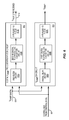
- FIG. 2A depicts an embodiment of the pseudo-envelope follower power management system of FIG. 1A in further detail.
- FIG. 2B depicts an embodiment of the pseudo-envelope follower power management system of FIG. 1B in further detail.
- FIG. 3A depicts an embodiment of programmable delay circuitry.
- FIG. 3B depicts another embodiment of the programmable delay circuitry.
- FIG. 4 depicts a further embodiment of the programmable delay circuitry.
- FIG. 5A depicts an embodiment of a parallel amplifier output impedance compensation circuit including a digital V RAMP pre-distortion filter circuit.
- FIG. 5B depicts an alternative embodiment of a parallel amplifier output impedance compensation circuit.
- FIG. 5C depicts another embodiment of a parallel amplifier output impedance compensation circuit including an analog V RAMP pre-distortion filter circuit.
- FIG. 5D depicts an alternative embodiment of a parallel amplifier output impedance compensation circuit.
- FIG. 5E depicts an alternative embodiment of a parallel amplifier output impedance compensation circuit.
- FIG. 6 depicts embodiments of the digital V RAMP pre-distortion filter and a V RAMP digital-to-analog (D/A) circuit.
- FIG. 7 depicts an example embodiment of a variable delay capacitor.
- a switch mode power supply converter, a parallel amplifier, and a parallel amplifier output impedance compensation circuit are disclosed.
- the switch mode power supply converter provides a current to a power amplifier supply output via an inductor.
- the parallel amplifier generates a power amplifier supply voltage at the power amplifier supply output based on a compensated V RAMP signal.
- the parallel amplifier output impedance compensation circuit compensates for a non-ideal output impedance of the parallel amplifier based on a combination of a V RAMP signal and a high frequency ripple compensation signal.
- the high frequency ripple compensation signal is based on a difference between the V RAMP signal and an estimated switching voltage output, which is provided by the switch mode power supply converter.
- the combination of the V RAMP signal and the high frequency ripple compensation signal is based on pre-filtering the V RAMP signal to equalize the overall frequency response of the switch mode power supply converter and the parallel amplifier to provide a proper transfer function of the switch mode power supply converter and the parallel amplifier.
- FIGS. 1A and 2A depict an example embodiment of a pseudo-envelope follower power management system 10 A including a multi-level charge pump buck converter 12 , a parallel amplifier circuit 14 , a power inductor 16 , a coupling circuit 18 , and a bypass capacitor 19 .
- the bypass capacitor 19 has a bypass capacitor capacitance, C BYPASS .
- the multi-level charge pump buck converter 12 and the parallel amplifier circuit 14 may be configured to operate in tandem to generate a power amplifier supply voltage, V CC , at a power amplifier supply output 28 of the pseudo-envelope follower power management system 10 A for a linear RF power amplifier 22 .
- the power amplifier supply output 28 provides an output current, I OUT , to the linear RF power amplifier 22 .
- the linear RF power amplifier 22 may include a power amplifier input, P IN , which is configured to receive a modulated RF signal, and a power amplifier output, P OUT , coupled to an output load, Z LOAD .
- the output load, Z LOAD may be an antenna.
- the multi-level charge pump buck converter 12 may include a supply input 24 , which is configured to receive a direct current (DC) voltage, V BAT , from a battery 20 , and a switching voltage output 26 , which is configured to provide a switching voltage, V SW .
- the switching voltage output 26 may be coupled to the power amplifier supply output 28 by the power inductor 16 , where the power inductor 16 couples to the bypass capacitor 19 to form an output filter 29 for the switching voltage output 26 of the multi-level charge pump buck converter 12 .
- the power inductor 16 provides an inductor current, I SW _ OUT , to the power amplifier supply output 28 .
- the parallel amplifier circuit 14 may include a parallel amplifier supply input 30 , which is configured to receive the DC voltage, V BAT , from the battery 20 , a parallel amplifier output 32 A, a first control input 34 , which is configured to receive a V RAMP signal, and a second control input configured to receive the power amplifier supply voltage, V CC .
- the parallel amplifier output 32 A of the parallel amplifier circuit 14 may be coupled to the power amplifier supply voltage V CC , by the coupling circuit 18 .
- a parallel amplifier output voltage, V PARA _ AMP is provided by the parallel amplifier circuit 14 via the parallel amplifier output 32 A.
- the parallel amplifier circuit 14 may generate the parallel amplifier output voltage, V PARA _ AMP , based on the difference between the V RAMP signal and the power amplifier supply voltage, V CC .
- the V RAMP signal may represent either an analog or digital signal that contains the required supply modulation information for a power amplifier collector of the linear RF power amplifier 22 .
- the V RAMP signal is provided to the parallel amplifier circuit 14 as a differential analog signal to provide common mode rejection against any noise or spurs that could appear on this signal.
- the V RAMP signal may be a time domain signal, V RAMP (t), generated by a transceiver or modem and used to transmit radio frequency (RF) signals.
- the V RAMP signal may be generated by a digital baseband processing portion of the transceiver or modem, where the digital V RAMP signal, V RAMP _ DIGITAL , is digital-to-analog converted to form the V RAMP signal in the analog domain.
- the “analog” V RAMP signal is a differential signal.
- the transceiver or a modem may generate the V RAMP signal based upon a known RF modulation Amp(t)*cos(2*pi*f RF *t+Phase(t)).
- the V RAMP signal may represent the target voltage for the power amplifier supply voltage, V CC , to be generated at the power amplifier supply output 28 of the pseudo-envelope follower power management system 10 A, where the pseudo-envelope follower power management system 10 A provides the power amplifier supply voltage, V CC , to the linear RF power amplifier 22 . Also the V RAMP signal may be generated from a detector coupled to the linear RF power amplifier 22 .
- the parallel amplifier circuit 14 includes the parallel amplifier output 32 A that provides the parallel amplifier output voltage, V PARA _ AMP , to the coupling circuit 18 .
- the parallel amplifier output 32 A sources a parallel amplifier circuit output current, I PAWA _ OUT , to the coupling circuit 18 .
- the parallel amplifier circuit 14 depicted in FIG. 1A and FIG. 1B , may provide a parallel amplifier circuit output current estimate 40 , I PAWA _ OUT _ EST , to the multi-level charge pump buck converter 12 as an estimate of the parallel amplifier circuit output current I PAWA _ OUT , of the parallel amplifier circuit 14 .
- the parallel amplifier circuit output current estimate 40 I PAWA _ OUT _ EST , represents an estimate of the parallel amplifier circuit output current I PAWA _ OUT , provided by the parallel amplifier circuit 14 as a feedback signal to the multi-level charge pump buck converter 12 .
- the multi-level charge pump buck converter 12 may be configured to control the switching voltage, V SW , provided at the switching voltage output 26 of the multi-level charge pump buck converter 12 .
- the coupling circuit 18 may be an offset capacitor, C OFFSET .
- An offset voltage, V OFFSET may be developed across the coupling circuit 18 .
- the coupling circuit 18 may be a wire trace such that the offset voltage, V OFFSET , between the parallel amplifier output voltage, V PARA _ AMP , and the power amplifier supply voltage, V CC , is zero volts.
- the coupling circuit 18 may be a transformer.
- a pseudo-envelope follower power management system 10 A depicted in FIG. 2A is an example embodiment of the pseudo-envelope follower power management system 10 depicted in FIG. 1A .
- the pseudo-envelope follower power management system 10 A depicted in FIG. 2A includes an embodiment of the multi-level charge pump buck converter 12 A and a parallel amplifier circuit 14 A having parallel amplifier circuitry 32 .
- the parallel amplifier circuitry 32 includes a parallel amplifier 35 and a parallel amplifier sense circuit 36 .
- the parallel amplifier circuit 14 A further includes a parallel amplifier output impedance compensation circuit 37 configured to receive the V RAMP signal and provide a compensated V RAMP signal, V RAMP _ C , to an input to the parallel amplifier 35 .
- the compensated V RAMP signal, V RAMP _ C is a function of the V RAMP signal.
- the parallel amplifier 35 generates a parallel amplifier output current, I PARA _ AMP , to produce a parallel amplifier output voltage, V PARA _ AMP , at the parallel amplifier output 32 A based on the difference between the compensated V RAMP signal, V RAMP _ C and the power amplifier supply voltage, V CC , generated at power amplifier supply output 28 .
- the parallel amplifier sense circuit 36 generates a scaled parallel amplifier output current estimate, I PARA _ AMP _ SENSE , which is a fractional representation of the parallel amplifier output current, I PARA _ AMP , generated by the parallel amplifier 35 .
- the parallel amplifier 35 generates the parallel amplifier output current, I PARA _ AMP , to produce the parallel amplifier output voltage, V PARA _ AMP , based on the difference between the V RAMP signal and the power amplifier supply voltage, V CC .
- the parallel amplifier circuit 14 A may further include an open loop assist circuit 39 configured to receive a feed forward control signal 38 , V SWITCHER , the scaled parallel amplifier output current estimate, I PARA _ AMP _ SENSE , and the V RAMP signal.
- the open loop assist circuit 39 may be configured to generate an open loop assist current, I ASSIST .
- the open loop assist current, I ASSIST may be provided to the parallel amplifier output 32 A.
- the parallel amplifier output current, I PARA _ AMP , generated by the parallel amplifier 35 and the open loop assist circuit current, I ASSIST , generated by the open loop assist circuit 39 , may be combined to form the parallel amplifier circuit output current, I PAWA _ OUT , of the parallel amplifier circuit 14 A.
- the parallel amplifier circuit 14 A may further include a V OFFSET loop circuit 41 configured to generate a threshold offset current 42 , I THRESHOLD _ OFFSET .
- the threshold offset current 42 , I THRESHOLD _ OFFSET may be provided from the parallel amplifier circuit 14 A as a feedback signal to the multi-level charge pump buck converter 12 A.
- the V OFFSET loop circuit 41 may be configured to provide a threshold offset current 42 , I THRESHOLD _ OFFSET , as an estimate of the magnitude of the offset voltage, V OFFSET , appearing across the coupling circuit 18 .
- the parallel amplifier circuit 14 A may not provide the threshold offset current 42 , I THRESHOLD _ OFFSET , to the multi-level charge pump buck converter 12 A.
- FIG. 2B Another example is the pseudo-envelope follower power management system 10 B depicted in FIG. 2B , which is similar to the embodiment of the pseudo-envelope follower power management system 10 B depicted in FIG. 1B .
- the pseudo-envelope follower power management system 10 B is operationally and functionally similar in form and function to the pseudo-envelope follower power management system 10 A is depicted in FIG. 2A .
- 2B includes a multi-level charge pump buck converter 12 B configured to generate an estimated switching voltage output 38 B, V SW _ EST , and a parallel amplifier circuit 14 B configured to receive the estimated switching voltage output 38 B, V SW _ EST , instead of the feed forward control signal 38 , V SWITCHER .
- the open loop assist circuit 39 of the parallel amplifier circuit 14 B is configured to use only the estimated switching voltage output 38 B, V SW _ EST , instead of the feed forward control signal 38 , V SWITCHER .
- the estimated switching voltage output 38 B, V SW _ EST provides an indication of the switching voltage, V SW .
- FIGS. 1A and 1B The generation of the parallel amplifier circuit output current estimate 40 , I PAWA _ OUT _ EST , depicted in FIGS. 1A and 1B will now be described with continuing reference to the embodiment of the parallel amplifier circuit 14 A, depicted in FIG. 2A , and the embodiment of the parallel amplifier circuit 14 B depicted in FIG. 2B .
- the parallel amplifier circuit output current estimate 40 I PAWA _ OUT _ EST , where the parallel amplifier circuit output current estimate 40 , I PAWA _ OUT _ EST , includes a scaled parallel amplifier output current estimate, I PARA _ AMP _ SENSE , and a scaled open loop assist circuit output current estimate, I ASSIST _ SENSE .
- the scaled parallel amplifier output current estimate, I PARA _ AMP _ SENSE is a scaled estimate of the parallel amplifier output current, I PARA _ AMP , generated by the parallel amplifier sense circuit 36 of the parallel amplifier circuitry 32 .
- the parallel amplifier 35 may generate the scaled estimate of the parallel amplifier output current, I PARA _ AMP _ SENSE , directly.
- the scaled open loop assist circuit current estimate, I ASSIST _ SENSE is a scaled estimate of the open loop assist circuit current, I ASSIST , generated by the open loop assist circuit 39 .
- the parallel amplifier circuit 14 does not include the open loop assist circuit 39 . In those embodiments of the parallel amplifier circuit 14 depicted in FIG. 1A and FIG.
- the parallel amplifier circuit output current estimate 40 may only be based on the scaled parallel amplifier output current estimate, I PARA _ AMP _ SENSE .
- the pseudo-envelope follower power management systems 10 A and 10 B may further include a control bus 44 coupled to a controller 50 .
- the control bus 44 may be coupled to a control bus interface 46 of the multi-level charge pump buck converter 12 and a control bus interface 48 of the parallel amplifier circuit 14 .
- the controller 50 may include various logical blocks, modules, and circuits.
- the controller 50 may be implemented or performed with a processor, a Digital Signal Processor (DSP), an Application Specific Integrated Circuit (ASIC), a Field Programmable Gate Array (FPGA) or other programmable logic device, discrete gate or transistor logic, discrete hardware components, or any combination thereof designed to perform the functions described herein.
- DSP Digital Signal Processor
- ASIC Application Specific Integrated Circuit
- FPGA Field Programmable Gate Array
- a processor may be a microprocessor, but in the alternative, the processor may be any conventional processor, controller, microcontroller, or state machine.
- a processor may also be implemented as a combination of computing devices.
- a combination of computing devices may include a combination of a DSP and a microprocessor, a plurality of microprocessors, one or more microprocessors in conjunction with a DSP core, or any other such configuration.
- the controller may further include or be embodied in hardware and in computer executable instructions that are stored in memory, and may reside, for example, in Random Access Memory (RAM), flash memory, Read Only Memory (ROM), Electrically Programmable ROM (EPROM), Electrically Erasable Programmable ROM (EEPROM), registers, hard disk, a removable disk, a CD-ROM, or any other form of computer readable medium known in the art.
- RAM Random Access Memory
- ROM Read Only Memory
- EPROM Electrically Programmable ROM
- EEPROM Electrically Erasable Programmable ROM
- registers hard disk, a removable disk, a CD-ROM, or any other form of computer readable medium known in the art.
- An exemplary storage medium may be coupled to the processor such that a processor can read information from, and write information to, the storage medium.
- the storage medium or a portion of the storage medium may be integral to the processor.
- the processor and the storage medium may reside in an ASIC.
- FIGS. 2A and 2B depict a pseudo-envelope follower power management system 10 A and a pseudo-envelope follower power management system 10 B, respectively, that include embodiments of the multi-level charge pump buck converter 12 A and the multi-level charge pump buck converter 12 B.
- some embodiments of the multi-level charge pump buck converter 12 of FIGS. 1A and 1B may include an FLL circuit 54 configured to interoperate with a switcher control circuit 52 .
- some embodiments of the multi-level charge pump buck converter 12 A and the multi-level charge pump buck converter 12 B may not include an FLL circuit 54 or be configured to operate with the FLL circuit 54 being disabled.
- some embodiments of the switcher control circuit 52 may be configured to control the operation of a multi-level charge pump circuit 56 and a switching circuit 58 to generate the switching voltage, V SW , on the switching voltage output 26 of the multi-level charge pump buck converter 12 A or the multi-level charge pump buck converter 12 B, respectively.
- the switcher control circuit 52 may use a charge pump mode control signal 60 to configure the operation of the multi-level charge pump circuit 56 to provide a charge pump output 64 to the switching circuit 58 .
- the switcher control circuit 52 may generate a series switch control signal 66 to configure the switching circuit 58 to provide the switching voltage, V SW , substantially equal to the DC voltage, V BAT , from the battery 20 via a first switching element coupled between the supply input 24 and the switching voltage output 26 .
- the switcher control circuit 52 may configure the switching circuit 58 to provide the switching voltage, V SW , through a second switching element coupled to ground such that the switching voltage, V SW , is substantially equal to ground.
- the parallel amplifier circuit 14 A depicted in FIG. 2A
- the parallel amplifier circuit 14 B depicted in FIG. 2B
- some embodiments of the switcher control circuit 52 may be configured to receive and use the parallel amplifier circuit output current estimate 40 , I PAWA _ OUT _ EST , the threshold offset current 42 , I THRESHOLD _ OFFSET , and/or a combination thereof to control the operation of the switcher control circuit 52 .
- the switcher control circuit 52 may use the parallel amplifier circuit output current estimate 40 , I PAWA _ OUT _ EST , the threshold offset current 42 , I THRESHOLD _ OFFSET , and/or a combination thereof to determine the magnitude of the voltage provided by the switching voltage, V SW , from the multi-level charge pump circuit 56 .
- FIG. 3A depicts an embodiment of programmable delay circuitry 432 A, where the embodiment of the programmable delay circuitry 432 A includes both fixed delay circuitry 635 and variable delay circuitry 640 A.
- the fixed delay circuitry 635 includes an input stage 642 including an input node 642 A, a first PFET 644 , PFET 1 , a first NFET 646 , NFET 1 , a first fixed current source 648 , a second fixed current source 650 , and a first fixed delay capacitor 652 .
- the first fixed delay capacitor 652 has a first delay capacitance, C DELAY1 .
- the input node 642 A of the input stage 642 is configured to receive an input voltage, V IN , having a digital logic level signal, where the digital logic level signal is to be delayed by the programmable delay circuitry 432 A.
- the input stage 642 is formed by coupling the gate of the first PFET 644 , PFET 1 , and the gate of the first NFET 646 , NFET 1 , to the input node 642 A.
- the first fixed current source 648 is coupled between a circuit supply voltage, V DD , and the source of the first PFET 644 , PFET 1 .
- the second fixed current source 650 is coupled between the source of the first NFET 646 , NFET 1 , and ground.
- the first fixed delay capacitor 652 is coupled between ground and the drain of the first PFET 644 , PFET 1 , and the drain of the first NFET 646 , NFET 1 .
- the first PFET 644 , PFET 1 is configured to be in a conducting state and the first NFET 646 , NFET 1 , is configured to be in a non-conducting state.
- the first fixed current source 648 sources a fixed bias current, I BIAS , to the first fixed delay capacitor 652 with a first fixed capacitor current, I C1 .
- I BIAS first fixed bias current
- the first fixed capacitor current, I C1 is substantially equal to the fixed bias current, I BIAS , provided from the first fixed current source 648 through first PFET 644 , PFET 1 .
- V D1 a first delay voltage
- the first PFET 644 , PFET 1 is configured to be in a non-conducting state and the first NFET 646 , NFET 1 , is configured to be in a conducting state.
- the second fixed current source 650 sinks a fixed bias current, I BIAS , from the first fixed delay capacitor 652 to generate the first fixed capacitor current, I C1 , of opposite magnitude than when the first fixed delay capacitor 652 is being charged by the first fixed current source 648 .
- the magnitude of the first fixed capacitor current, I C1 is substantially equal to the magnitude of the fixed bias current, I BIAS , sunk by the second fixed current source 650 through the first NFET 646 , NFET 1 .
- the first delay voltage, V D1 continues to decrease and eventually falls below a voltage level that is less than a logic low threshold voltage that may trigger an action by the variable delay circuitry 640 A.
- the first fixed current source 648 and the second fixed current source 650 each source and sink, respectively, a current equal to the fixed bias current, I BIAS , the first fixed delay capacitor 652 is charged and discharged at the same rate.
- the first fixed delay time associated with the fixed delay circuitry 635 is due to the generation of the first delay voltage, V D1 . Because the current sourced by the first fixed current source 648 and sunk by the second fixed current source 650 are substantially equal, the rise time and fall time of the first delay voltage, V D1 , are substantially equal.
- the first fixed delay time is due to the time required to propagate the digital logic state represented by the input voltage, V IN , through the fixed delay circuitry 635 and provide the first delay voltage, V D1 , that represents a digital logic state to an input stage 654 of the variable delay circuitry 640 A.
- the variable delay circuitry 640 A includes the input stage 654 having an input node 654 A coupled to the drain of the first PFET 644 , PFET 1 , the drain of the first NFET 646 , NFET 1 , and the first fixed delay capacitor 652 .
- the variable delay circuitry 640 A further includes a second PFET 656 , PFET 2 , a second NFET 658 , NFET 2 , a first variable current source 660 , a second variable current source 662 , and a second fixed delay capacitor 664 .
- the second fixed delay capacitor 664 has a second delay capacitance, C DELAY2 .
- the input stage 654 of the variable delay circuitry 640 A is formed by coupling the gate of the second PFET 656 , PFET 2 , and the gate of the second NFET 658 , NFET 2 , to the input node 654 A.
- the variable delay circuitry 640 A is further formed by coupling the first variable current source 660 between the circuit supply voltage, V DD , and the source of the second PFET 656 , PFET 2 , such that the first variable current source 660 may provide a variable bias current, I BIAS _ VAR , to the source of the second PFET 656 , PFET 2 when the second PFET 656 , PFET 2 , is in a conducting state.
- the second variable current source 662 is coupled between the source of the second NFET 658 , NFET 2 , and ground such that the second variable current source 662 may sink a variable bias current, I BIAS _ VAR , from the source of the second NFET 658 , NFET 2 , when the second NFET 658 , NFET 2 , is in a conducting state.
- the second fixed delay capacitor 664 is coupled between ground and the drain of the second PFET 656 , PFET 2 , and the drain of the second NFET 658 , NFET 2 .
- variable delay circuitry 640 A further includes an output buffer stage 666 that includes a third PFET 668 , PFET 3 operably coupled to a third NFET 670 , NFET 3 to form an input node 666 A.
- the output buffer stage 666 includes an input node 666 A formed by coupling the gate of the third PFET 668 , PFET 3 , to the gate of the third NFET 670 , NFET 3 .
- the source of the third PFET 668 , PFET 3 is coupled to the circuit supply voltage, V DD .
- the source of the third NFET 670 , NFET 3 is coupled to ground.
- the output buffer stage 666 further includes an output buffer stage output 672 that corresponds to the output of the programmable delay circuitry 432 A.
- the output buffer stage output 672 may be formed by coupling the drain of the third PFET 668 , PFET 3 , to the drain of the third NFET 670 , NFET 3 .
- the output buffer stage 666 is configured to generate an output voltage, V OUT , at the output buffer stage output 672 .
- the output voltage, V OUT generated by the output buffer stage 666 at the output buffer stage output 672 will represent either a digital logic high state or a digital logic low state.
- the output voltage, V OUT when the output voltage, V OUT , is substantially equal to the circuit supply voltage, V DD , the output voltage, V OUT , represents a digital logic high state.
- the output voltage, V OUT when the output voltage, V OUT , is substantially equal to the ground voltage, the output voltage, V OUT , represents a digital logic low state.
- a second delay voltage, V D2 increases as the second fixed delay capacitor 664 is charged and decreases as the second fixed delay capacitor 664 is discharged.
- the third PFET 668 , PFET 3 is configured to be in a conducting state and the third NFET 670 , NFET 3 is configured to be in a non-conducting state.
- the output buffer stage output 672 is coupled to the circuit supply voltage, V DD , via the third PFET 668 , PFET 3 .
- the output voltage, V OUT at the output buffer stage output 672 is substantially equal to the circuit supply voltage, V DD , and the output voltage, V OUT , represents a digital logic high state.
- the third PFET 668 , PFET 3 is configured to be in a non-conducting state and the third NFET 670 , NFET 3 is configured to be in a conducting state.
- the third NFET 670 , NFET 3 is turned on and the output buffer stage output 672 is coupled to ground via the third NFET 670 , NFET 3 .
- the output voltage, V OUT at the output buffer stage output 672 is substantially equal to the ground voltage, and the output voltage, V OUT , represents a digital logic low state.
- the second PFET 656 , PFET 2 is configured to be in a conducting state and the second NFET 658 , NFET 2 , is configured to be in a non-conducting state. Accordingly, when the second PFET 656 , PFET 2 , is turned on, the first variable current source 660 sources the variable bias current, I BIAS _ VAR , through the second PFET 656 , PFET 2 , to charge the second fixed delay capacitor 664 with a second fixed capacitor current, I C2 .
- the second fixed capacitor current, I C2 is substantially equal to the variable bias current, I BIAS _ VAR , provided by the first variable current source 660 .
- the magnitude of the second delay voltage, V D2 continues to increase and eventually rises above a voltage level that is greater than the logic high threshold voltage that may trigger an action by the output buffer stage 666 . For example, once the second delay voltage, V D2 , reaches or exceeds the logic high threshold voltage, the output buffer stage 666 will trigger so as to generate an output voltage, V OUT that represents a digital logic low state.
- the second PFET 656 , PFET 2 is configured to be in a non-conducting state and the second NFET 658 , NFET 2 , is configured to be in a conducting state. Accordingly, when the second NFET 658 , NFET 2 , is turned on, the second variable current source 662 sinks the variable bias current, I BIAS _ VAR , through the second NFET 658 , NFET 2 , to discharge the second fixed delay capacitor 664 with the second fixed capacitor current, I C2 , by removing charge from the second fixed delay capacitor 664 .
- the magnitude of the second fixed capacitor current, I C2 that removes charge from the second fixed delay capacitor 664 is substantially equal to the variable bias current, I BIAS _ VAR , sunk by second variable current source 662 .
- the magnitude of the second delay voltage, V D2 continues to decrease or eventually fall below a voltage level that is less than the logic low threshold voltage that may trigger an action by the output buffer stage 666 . For example, once the second delay voltage, V D2 , reaches or falls below the logic low threshold voltage, the output buffer stage 666 will trigger, and the output buffer stage 666 will generate an output voltage, V OUT , that represents a digital logic high state.
- variable delay time provided by the variable delay circuitry 640 A is created by the time period required to charge and discharge the second fixed delay capacitor 664 with the variable bias current, I BIAS _ VAR , where the variable bias current, I BIAS _ VAR , varies in magnitude.
- the first variable current source 660 and the second variable current source 662 are each configured to respectively source and sink currents that are both equal to the variable bias current, I BIAS _ VAR .
- the variable delay time of the variable delay circuitry 640 A is symmetrically divided into equal parts.
- the first variable current source 660 and the second variable current source 662 may source and sink different magnitudes of current.
- the time to charge and discharge the second fixed delay capacitor 664 such that the magnitude of the second delay voltage, V D2 , changes logic state represented by the output voltage, V OUT , at the output buffer stage output 672 may change.
- the controller 50 may be configured to control the programmable delay circuitry 432 A. Accordingly, although not depicted in FIG. 3A , in some embodiments of the programmable delay circuitry 432 A, the controller 50 may be further configured to control the first variable current source 660 and the second variable current source 662 to set the magnitude of the variable bias current, I BIAS _ VAR , and thereby the variable delay time provided by the variable delay circuitry 640 A.
- FIG. 3B depicts the programmable delay circuitry 432 B, which is another embodiment of the programmable delay circuitry.
- the embodiment of the programmable delay circuitry 432 B, depicted in FIG. 3B is similar to the programmable delay circuitry 432 A, depicted in FIG. 3A , except the embodiment of the variable delay circuitry 640 A, depicted in FIG. 3A , is replaced by the variable delay circuitry 640 B, depicted in FIG. 3B .
- the programmable delay circuitry 432 B is similar to the programmable delay circuitry 432 A, depicted in FIG. 3A , except the first variable current source 660 , the second variable current source 662 , and the second fixed delay capacitor 664 are replaced, respectively, with a third fixed current source 674 , a fourth fixed current source 678 , and a variable delay capacitor 680 .
- the voltage across the variable delay capacitor 680 is the third voltage, V D3 .
- the variable delay capacitor 680 having a variable delay capacitance C DELAY _ VAR , where the capacitance value of the variable delay capacitance C DELAY _ VAR may be programmatically configured.
- the operational parameters of the programmable delay circuitry 432 B may be configured by the controller 50 ( FIG. 1A ).
- the variable delay capacitor 680 may be a capacitor array or a varactor under the control of the controller 50 .
- the controller 50 may be configured to increase the variable delay capacitance, C DELAY _ VAR , of the variable delay capacitor 680 in order to increase the delay time provided by the programmable delay circuitry 432 B.
- the controller 50 may be configured to decrease the variable delay capacitance, C DELAY _ VAR , of the variable delay capacitor 680 to decrease the delay time provided by the programmable delay circuitry 432 B.
- the function and operation of the fixed delay circuitry 638 of the programmable delay circuitry 432 B, and thereby the fixed delay time provided by the fixed delay circuitry 638 are substantially the same in the programmable delay circuitry 432 B, depicted in FIG. 3B . Accordingly, description of the fixed delay circuitry 638 is omitted.
- variable delay circuitry 640 B is similar to the variable delay circuitry 640 A except that the variable delay circuitry 640 B replaces the first variable current source 660 , the second variable current source 662 , and the second fixed delay capacitor 664 of the variable delay circuitry 640 A, with the third fixed current source 674 , the fourth fixed current source 678 , and the variable delay capacitor 680 , respectively.
- variable delay circuitry 640 B includes the input stage 654 having the input node 654 A, the second PFET 656 , PFET 2 , the second NFET 658 , NFET 2 , the third fixed current source 674 , the fourth fixed current source 678 , and the variable delay capacitor 680 having a variable delay capacitance, C DELAY _ VAR , where the controller 50 (not shown) may be configured to change the capacitance value of the variable delay capacitance, C DELAY _ VAR .
- variable delay circuitry 640 B also includes the output buffer stage 666 that includes the third PFET 668 , PFET 3 , and the third NFET 670 , NFET 3 .
- the output buffer stage 666 includes the input node 666 A formed by coupling the gate of the third PFET 668 , PFET 3 , to the gate of the third NFET 670 , NFET 3 .
- the source of the third PFET 668 , PFET 3 is coupled to the circuit supply voltage, V DD .
- the source of the third NFET 670 , NFET 3 is coupled to ground.
- the output buffer stage output 672 of the output buffer stage 666 which is also the output of the programmable delay circuitry 432 B, is formed by coupling the drain of the third PFET 668 , PFET 3 , to the drain of the third NFET 670 , NFET 3 .
- the output buffer stage 666 is configured to generate an output voltage, V OUT , at the output buffer stage output 672 .
- a third delay voltage, V D3 , across the variable delay capacitor 680 increases and decreases at a rate that depends on the capacitance value of the variable delay capacitance, C DELAY _ VAR , of the variable delay capacitor 680 and the magnitude of a variable delay capacitor current, I C _ VAR , that charges and discharges the variable delay capacitor 680 .
- the third PFET 668 , PFET 3 When the third delay voltage, V D3 , across the variable delay capacitor 680 is sufficiently low such that the third delay voltage, V D3 is substantially equal to a logic low threshold voltage, the third PFET 668 , PFET 3 , is configured to be in a conducting state and the third NFET 670 , NFET 3 , is configured to be in a non-conducting state. In this case, when the third PFET 668 , PFET 3 , is turned on, the output buffer stage output 672 is coupled to the circuit supply voltage, V DD .
- the output voltage, V OUT , at the output buffer stage output 672 is substantially equal to the circuit supply voltage, V DD , when the third PFET 668 , PFET 3 , is in the conducting state.
- the third delay voltage, V D3 across the variable delay capacitor 680 is sufficiently high such that the third delay voltage, V D3 is substantially equal to a logic high threshold voltage
- the third NFET 670 , NFET 3 is configured to be in a conducting state
- the third PFET 668 , PFET 3 is configured to be in a non-conducting state.
- the output buffer stage output 672 is coupled to ground.
- the output voltage, V OUT , at the output buffer stage output 672 is substantially equal to the ground voltage when the third NFET 670 , NFET 3 , is turned on. In this way, the output voltage, V OUT , at the output buffer stage output 672 toggles between a digital logic high state and a logic log state.
- variable delay circuitry 640 B includes an input stage 654 having an input node 654 A configured to receive the signal generated by the charging and discharging of the first fixed delay capacitor 652 , where the first fixed delay capacitor 652 has a capacitance value substantially equal to the first fixed delay capacitance, C DELAY1 .
- the voltage generated across the first fixed delay capacitor 652 is substantially equal to the first delay voltage, V D1 .
- the input stage 654 is formed by coupling the gate of the second PFET 656 , PFET 2 , and the gate of the second NFET 658 , NFET 2 , to the input node 654 A.
- the third fixed current source 674 is coupled between the circuit supply voltage, V DD , and the source of the second PFET 656 , PFET 2 .
- the fourth fixed current source 678 is coupled between the source of the second NFET 658 , NFET 2 , and ground.
- the variable delay capacitor 680 is coupled between ground and the drain of the second PFET 656 , PFET 2 , and the drain of the second NFET 658 .
- the second PFET 656 PFET 2
- the third fixed current source 674 sources a second fixed bias current, I BIAS2 , to charge the variable delay capacitor 680 .
- the second fixed bias current, I BIAS2 charges the variable delay capacitor 680 with a variable delay capacitor current, I C _ VAR .
- the rate of change in the third delay voltage, V D3 , across the variable delay capacitor 680 depends upon the capacitance value of the variable delay capacitance, C DELAY _ VAR , of the variable delay capacitor 680 and the magnitude of the variable delay capacitor current, I- C _ VAR .
- the variable delay capacitor current, I C _ VAR is substantially equal to the second fixed bias current, I BIAS2 .
- variable delay capacitor 680 As the variable delay capacitor 680 is charged by the second fixed bias current, I BIAS2 , the magnitude of the third delay voltage, V D3 , increases. As described above, after the third delay voltage, V D3 , increases to a logic high threshold voltage, the third PFET 668 , PFET 3 , is turned off and the third NFET 670 , NFET 3 , is turned on, which changes the output voltage, V OUT , at the output buffer stage output 672 to be substantially equal to ground.
- the second NFET 658 , NFET 2 is configured to be in a conducting state and the fourth fixed current source 678 is permitted to sink a second fixed bias current, I BIAS2 , in order to discharges the variable delay capacitor 680 .
- the first delay voltage, V D1 at the input node 654 A is sufficiently low to turn on the second NFET 658 , NFET 2 , the second PFET 656 , PFET 2 , is configured to be in a non-conducting state.
- the fourth fixed current source 678 sinks the second fixed bias current, I BIAS2 , to discharge the variable delay capacitor 680 with a current substantially equal to I C _ VAR .
- the rate of change in the third delay voltage, V D3 , across the variable delay capacitor 680 depends upon the capacitance value of the variable delay capacitance, C DELAY _ VAR , of the variable delay capacitor 680 and the magnitude of the variable delay capacitor current, I C _ VAR .
- variable delay capacitor current I C _ VAR
- the magnitude of the third delay voltage, V D3 decreases.
- the third NFET 670 , NFET 3 is turned off and the third PFET 668 , PFET 3 , is turned on, which changes the output voltage, V OUT , at the output buffer stage output 672 to be substantially equal to the circuit supply voltage, V DD .
- variable delay time provided by the variable delay circuitry 640 B is created by the time period required to charge and discharge the variable delay capacitor 680 , which depends upon the capacitance value of the variable capacitance, C DELAY _ VAR , and the magnitude of the second fixed bias current, I BIAS2 .
- variable delay capacitor 680 is either charged or discharged using a current substantially equal to the second fixed bias current, I BiAS2 , either sourced by the third fixed current source 674 or sunk by the fourth fixed current source 678 , the variable time period required for the third delay voltage, V D3 , to increase to the logic high threshold voltage or decrease to the logic high threshold voltage used to trigger the operation of the operation of the output buffer stage 666 is dependent upon the variable capacitance, C DELAY _ VAR of the variable delay capacitor 680 .
- the controller 50 may be configured to control the programmable delay circuitry 432 B. Accordingly, although not depicted in FIG. 3B , in some embodiments of the programmable delay circuitry 432 B, the controller 50 may be further configured to control the variable capacitance, C DELAY _ VAR of the variable delay capacitor 680 in order to change the delay time provided by the programmable delay circuitry 432 B. Assuming that the third fixed current source 674 and the fourth fixed current source 678 respectively source and sink the second fixed bias current, I BIAS2 , where the second fixed bias current, I BIAS2 , is constant, the variable delay capacitor current, I C _ VAR , will likewise be constant.
- variable delay time provided by the variable delay circuitry 640 B when charging the variable delay capacitor 680 is substantially equal to the variable delay time provided by the variable delay circuitry 640 B when discharging the variable delay capacitor 680 .
- the third fixed current source 674 and the fourth fixed current source 678 could be configured to source and sink different magnitudes of current. In this case, the variable delay time of the variable delay circuitry 640 B would have a charging period and a discharging period, where the charging period would not equal the discharging period.
- Programmable delay circuitry which includes an input buffer circuit and variable delay circuitry, is disclosed.
- the variable delay circuitry includes an input stage, a correction start voltage circuit, and a variable delay capacitor.
- the input buffer circuit is coupled to the input stage, the correction start voltage circuit is coupled to the input stage, and the variable delay capacitor is coupled to the input stage.
- the programmable delay circuitry is configured to provide a fixed time delay and a variable time delay.
- the correction start voltage circuit helps stabilize the variable time delay by reducing disturbances in a voltage across the variable delay capacitor when certain transistor elements in the programmable delay circuitry transition to be in a conducting state. Further, the correction start voltage circuit may improve accuracy of the variable time delay by reducing transition times of certain transistor elements in the programmable delay circuitry.
- the programmable delay circuitry further includes a voltage divider circuit and a bias current and mirror circuit.
- the voltage divider circuit is coupled to the bias current and mirror circuit.
- the bias current and mirror circuit is coupled to the variable delay circuitry.
- the voltage divider circuit and the bias current and mirror circuit are configured to reduce changes in the variable time delay due to changes in a voltage level of a circuit supply voltage, which is provided to the programmable delay circuitry.
- FIG. 4 depicts programmable delay circuitry 432 C, which is another embodiment of the programmable delay circuitry.
- the controller 50 FIG. 1A
- the controller 50 may be configured to control, configure, align, or change the parameter values and functions of the various circuits and elements to be described as being part of or related to the embodiment of the programmable delay circuitry 432 C, depicted in FIG. 4 .
- the programmable delay circuitry 432 C depicted in FIG. 4 is configured to delay a single digital logic level signal. It will be understood that alternate embodiments may include multiple embodiments of the programmable delay circuitry 432 C arranged in parallel to provide a delay signal path for each of the multiple digital logic level signals to be delayed.
- total delay time provided by the programmable delay circuitry 432 C may include a fixed delay time and a variable delay time, where the variable delay time may be configured based on the programmable delay parameter(s), as discussed above.
- the fixed delay time may be sub-divided and distributed between an input buffer circuit 682 and variable delay circuitry 684 .
- the programmable delay circuitry 432 C includes an input buffer circuit 682 , a variable delay circuitry 684 , a voltage divider circuit 686 , and a bias current and mirror circuit 688 .
- the input buffer circuit 682 may include a first input buffer circuit 690 having a first input buffer input 690 A configured to receive an input voltage, V IN , where the input voltage, V IN , is a digital logic level signal.
- the digital logic signal may have either a digital logic high state or a digital logic low state.
- the digital logic signal may have either a digital logic high state or a digital logic low state.
- the first input buffer circuit 690 may include a first PFET 692 , PFET 1 , and a first NFET 694 , NFET 1 .
- the gate of the first PFET 692 , PFET 1 , and the gate of the first NFET 694 , NFET 1 may be coupled to form the first input buffer input 690 A of the first input buffer circuit 690 .
- the source of the first PFET 692 , PFET 1 may be coupled to the circuit supply voltage, V DD .
- the source of the first NFET 694 , NFET 1 may be coupled to ground.
- the drain of the first PFET 692 , PFET 1 , and the drain of the first NFET 694 , NFET 1 may be coupled to form a first input buffer output at a first voltage node 696 .
- the input buffer circuit 682 may further include a second input buffer circuit 698 operably coupled to the first input buffer output at the first voltage node 696 .
- the second input buffer circuit 698 may include a second PFET 700 , PFET 2 , and a second NFET 702 , NFET 2 .
- the gate of the second PFET 700 , PFET 2 , and the gate of the second NFET 702 , NFET 2 may be coupled to the drain of the first PFET 692 , PFET 1 , and the drain of the first NFET 694 , NFET 2 , at the first voltage node 696 .
- the source of the second PFET 700 , PFET 2 may be coupled to the circuit supply voltage, V DD .
- the source of the second NFET 702 , NFET 2 may be coupled to ground.
- the drain of the second PFET 700 , PFET 2 , and the drain of the second NFET 702 , NFET 2 may be coupled to form a second input buffer output at a second voltage node 704 .
- the first PFET 692 PFET 1
- the first PFET 692 PFET 1
- the first input buffer circuit 690 provides an output voltage level representative of a digital logic high state at the first voltage node 696 .
- the first NFET 694 NFET 1
- the first NFET 694 is configured to be in a non-conducting state when the input voltage, V IN , at the first input buffer input 690 A is sufficiently low such that the input voltage, V IN is substantially equal to or less than the logic low threshold voltage.
- the first NFET 694 NFET 1
- the first input buffer circuit 690 provides an output voltage level representative of a digital logic low state at the first voltage node 696 .
- the first PFET 692 PFET 1
- the first PFET 692 is configured to be in a non-conducting state when the input voltage, V IN , at the first input buffer input 690 A is sufficiently high such that the input voltage, V IN is substantially equal to or greater than the logic high threshold voltage.
- the operation of the second input buffer circuit 698 is dependent on the voltage level at the first voltage node 696 , which is coupled to the first input buffer output of the first input buffer circuit 690 . Accordingly, when the first input buffer circuit 690 provides a digital logic low state at the first voltage node 696 such that the voltage level at the first voltage node 696 is substantially equal to or less than the logic low threshold voltage, the second PFET 700 , PFET 2 , is configured to be in a conducting state and couples the circuit supply voltage, V DD , to the second voltage node 704 .
- the voltage level at the second input buffer circuit 698 is substantially equal to the circuit supply voltage, V DD , and the second input buffer circuit 698 provides a digital logic high state at the second voltage node 704 .
- the second NFET 702 , NFET 2 is configured to be in a non-conducting state when the first input buffer circuit 690 provides an output voltage level representative of a digital logic low state at the first voltage node 696 .
- the second NFET 702 , NFET 2 is configured to be in a conducting state and couples the second voltage node 704 to ground.
- the voltage level at the second input buffer circuit 698 is substantially equal to the ground voltage
- the second input buffer circuit 698 provides a digital logic low state at the second voltage node 704 .
- the second PFET 700 , PFET 2 is configured to be in a non-conducting state when the first input buffer circuit 690 provides an output voltage level representative of a digital logic high state at the first voltage node 696
- the propagation time of the digital logic level signal, represented by the input voltage, V IN , through the input buffer circuit may be considered as a first portion of a fixed delay provided by the programmable delay circuitry 432 C and is a function of the switching time of the transistors.
- the first portion of the fixed delay time provided by the input buffer circuit 682 depends upon the switching time of the respective first input buffer circuit 690 and the second input buffer circuit 698 .
- additional input buffer circuits may be added to the input buffer circuit 682 to increase the first portion of the fixed delay provided by the input buffer circuit 682 .
- the combination of the first input buffer circuit 690 and the second input buffer circuit 698 may also provide the further benefit of isolating analog characteristics of the input voltage, V IN , that represents the digital logic level signal from the variable delay circuitry.
- the number of input buffer circuits used to provide isolation between the input voltage, V IN , and the variable delay circuitry 684 may result in improved controllability of the variable delay provided by the variable delay circuitry 684 .
- the variable delay circuitry 684 includes an input stage 706 including a third PFET 708 , PFET 3 , a third NFET 710 , NFET 3 , a fourth PFET 714 , PFET 4 , a fourth NFET 716 , NFET 4 , a fifth PFET 718 , PFET 5 , and a fifth NFET 720 , NFET 5 .
- variable delay capacitor 722 may be coupled between a third voltage node 724 and ground.
- the variable delay capacitor 722 is configured to have a variable delay capacitance, C DELAY _ VAR .
- the controller 50 FIG. 1A
- the controller 50 may be configured to govern or set various parameters to adjust the capacitance value of the variable delay capacitance, C DELAY _ VAR , in order to adjust the variable delay time, T VARIABLE _ DELAY _ TIME , provided by the variable delay circuitry 684 .
- variable delay capacitor 722 may be configured to couple to the controller 50 (not shown), where the controller 50 is configured to control the capacitance value of the variable delay capacitance, C DELAY _ VAR .
- the variable delay capacitor 722 may be configured to increase as the value of a binary capacitor control word, CNTR_CD, increases, as described relative to FIG. 7 .
- the variable delay capacitor 722 may be configured as a programmable capacitor array.
- the programmable capacitor array may include multiple capacitors, where each of the capacitors is arranged in series with a switch element. Each switch element may have a switch state (open or closed) that may be controlled by the controller 50 such that the effective capacitance of the programmable capacitor array has a desired effective capacitance.
- the programmable capacitor array may be a linear capacitor array, where each of the capacitors has the same value. In other embodiments, the programmable capacitor array may be a binary weighted capacitor array.
- the controller 50 may adjust the effective capacitance of the programmable capacitor array by controlling the switch state (open or closed) of each switch to combine different combinations of the multiple capacitors in parallel.
- the variable delay capacitor 722 may be a programmable varactor configured to be controlled by the controller 50 .
- the controller 50 may govern the effective capacitance of the programmable varactor by changing the distance between the two parallel plates that form the varactor or a voltage applied across the terminals of the varactor.
- the variable delay circuitry 684 may further include an output buffer stage 726 .
- the output buffer stage 726 depicted in FIG. 4 includes only one level of output buffering.
- the output buffer stage 726 includes a sixth PFET 728 , PFET6, and a sixth NFET 730 , NFET 6 , operably coupled to form an output buffer having an output buffer output 732 .
- the output buffer output 732 is formed by coupling the drain of the sixth PFET 728 , PFET6, to the drain of the sixth NFET 730 , NFET 6 .
- the source of the sixth PFET 728 , PFET6, is coupled to the circuit supply voltage, V DD .
- the source of the sixth NFET 730 , NFET 6 is coupled to ground.
- variable delay circuitry 684 may include an embodiment of the output buffer stage 726 that includes multiple levels of output buffering in order to provide additional isolation between the interior circuitry of the variable delay circuitry 684 and the digital logic level signal to be generated by the programmable delay circuitry 432 C.
- variable delay circuitry 684 may include additional output buffering to improve the drive level at the output of the programmable delay circuitry 432 C.
- the operation of the output buffer stage 726 depends upon the voltage level at the third voltage node 724 .
- the voltage level at the third voltage node 724 is equal to or less than the logic low threshold voltage such that the sixth PFET 728 , PFET 6 , is turned on and in the saturation state
- the output buffer output 732 is effectively coupled to the circuit supply voltage, V DD , through the sixth PFET 728 , PFET 6 .
- the sixth NFET 730 , NFET 6 is configured to be turned off when the sixth PFET 728 , PFET 6 is turned on.
- the output buffer stage 726 provides an output voltage, V OUT , substantially equal to the circuit supply voltage, V DD , which represents a digital logic high state.
- V OUT the output buffer stage 726 is triggered to transition from a digital logic low state to a digital logic low state at the output buffer output 732 .
- the output buffer output 732 is effectively coupled to the ground through the sixth NFET 730 , NFET 6 .
- the sixth PFET 728 , PFET 6 is configured to be turned off when the sixth NFET 730 , NFET 6 is turned on.
- the output buffer stage 726 provides an output voltage, V OUT , substantially equal to ground, which represents a digital logic low state.
- the output buffer stage 726 is triggered to transition from a digital logic high state to a digital logic low state at the output buffer output 732 .
- the time period during which the digital logic level signal, represented by the voltage level at the third voltage node 724 , propagates through the output buffer stage 726 may be a second portion of the fixed delay time provided by the programmable delay circuitry 432 C.
- the second portion of the fixed delay time provided by the output buffer stage 726 depends on the switching time of the output buffer stage 726 .
- Some alternative embodiments of the variable delay circuitry 684 may include additional output buffering. Accordingly, the propagation time through the output buffer stage of the variable delay circuitry 684 may be increased by addition of additional output buffering.
- the fixed delay time of the programmable delay circuitry 432 C includes the first portion of the fixed delay time of the input buffer circuit 682 and the second portion of the fixed delay time of the output buffer stage 726 .
- the gate of the fourth PFET 714 , PFET 4 , and the gate of the fourth NFET 716 , NFET 4 are coupled to the second input buffer output at the second voltage node 704 .
- the source of the fourth PFET 714 , PFET 4 is coupled to the drain of the fifth PFET 718 , PFET 5 .
- the source of the fifth PFET 718 , PFET 5 is coupled to the circuit supply voltage, V DD .
- the source of the fourth NFET 716 , NFET 4 is coupled to the drain of the fifth NFET 720 , NFET 5 .
- the source of the fifth NFET 720 , NFET 5 is coupled to ground.
- the bias current and mirror circuit 688 is configured to generate a first gate voltage on the gate of the fifth PFET 718 , PFET 5 , such that the fifth PFET 718 , PFET 5 , is configured to provide a first bias current, I BIAS _ 1 , when the fourth PFET 714 , PFET 4 , is turned on.
- the bias current and mirror circuit 688 is further configured to generate a second gate voltage on the gate of the fifth NFET 720 , NFET 5 , such that the fifth NFET 720 , NFET 5 , is configured to sink a second bias current, I BIAS _ 2 , when the fourth NFET 716 , PFET 4 , is turned on.
- the drain of the fourth PFET 714 , PFET 4 is coupled to the drain of the fourth NFET 716 , NFET 4 , to provide an input stage output at the third voltage node 724 .
- the variable delay capacitor 722 is coupled between the third voltage node 724 and ground.
- variable delay capacitor 722 is coupled to the drain of the fourth PFET 714 , PFET 4 , the drain of the fourth NFET 716 , NFET 4 , the gate of the sixth PFET 728 , PFET 6 , and the gate of the sixth NFET 730 , NFET 6 .
- the fourth PFET 714 , PFET 4 , and the fourth NFET 716 , NFET 4 are configured such that when the fourth PFET 714 , PFET 4 , is in a conducting mode of operation (ON), the fourth NFET 716 , NFET 4 , is in a non-conducting mode (OFF).
- the fourth PFET 714 , PFET 4 , and the fourth NFET 716 , NFET 4 are configured such that when the fourth NFET 716 , NFET 4 , is in a conducting mode (ON) of operation, the fourth PFET 714 , PFET 4 , is in a non-conducting mode (OFF).
- the fixed delay time of the programmable delay circuitry 432 C may further include a third portion of the fixed delay time, where the third portion of the fixed delay time is associated with the switching time of the fourth PFET 714 , PFET 4 , and the switching time of the fourth NFET 716 , NFET 4 .
- the first bias current, I BIAS _ 1 passes through the fourth PFET 714 , PFET 4 , pushes charge into the variable delay capacitor 722 to charge the variable delay capacitor 722 .
- the voltage across the variable delay capacitor 722 which is substantially equal to the voltage level on the third voltage node 724 , increases.
- the second bias current, I BIAS _ 2 sunk by the fifth NFET 720 , NFET 5 , passes through the fourth NFET 716 , NFET 4 , and pulls charge from the variable delay capacitor 722 to discharge the variable delay capacitor 722 .
- the voltage across the variable delay capacitor 722 which is substantially equal to the voltage level on the third voltage node 724 , falls.
- the correction start voltage circuit 712 is formed by coupling the gate of the third PFET 708 , PFET 3 and the gate of the third NFET 710 , NFET 3 , to the second voltage node 704 , such that the gates of the third PFET 708 , PFET 3 , the third NFET 710 , NFET 3 , the fourth PFET 714 , PFET 4 , and the fourth NFET 716 , NFET 4 , are coupled.
- the source of the third PFET 708 , PFET 3 is coupled to the circuit supply voltage, V DD .
- the drain of the third PFET 708 , PFET 3 is coupled to the source of the fourth NFET 716 , NFET 4 , and the drain of the fifth NFET 720 , NFET 5 .
- the source of the third NFET 710 , NFET 3 is coupled to ground.
- the drain of the third NFET 710 , NFET 3 is coupled to the source of the fourth PFET 714 , PFET 4 , and the drain of the fifth PFET 718 , PFET 5 .
- the correction start voltage circuit 712 is configured to provide a first known voltage level at the source of the fourth PFET 714 , PFET 4 , while the fourth PFET 714 , PFET 4 , is in the non-conducting state such that the voltage level present at the source of the fourth PFET 714 , PFET 4 , is at the first known voltage level at the moment the fourth PFET 714 , PFET 4 transitions from the non-conducting state to the conducting state.
- the third NFET 710 , NFET 3 is configured to be turned on when the while the fourth PFET 714 , PFET 4 , is in the non-conducting state.
- the source of the fourth PFET 714 , PFET 4 is coupled to ground through the third NFET 710 , NFET 3 .
- the first known voltage is substantially equal to ground.
- the source of the third NFET 710 , NFET 3 . may be coupled to a voltage level other than ground such that the first known voltage is not substantially equal to ground.
- the correction start voltage circuit 712 may be configured such that the first known voltage is substantially equal to one half the circuit supply voltage, V DD /2.
- the parasitic capacitance of the source of the fourth PFET 714 , PFET 4 , the parasitic capacitance of the drain of the fifth PFET 718 , PFET 5 , and/or a combination thereof is configured such that the voltage level present on the source of the fourth PFET 714 , PFET 4 , remains at the first known voltage level momentarily at the moment the fourth PFET 714 , PFET 4 transitions from the non-conducting state to the conducting state.
- the parasitic capacitance of the drain of the third NFET 710 , NFET 3 may also be configured to improve the ability of the correction start voltage circuit 712 to provide the first known voltage on the source of the fourth PFET 714 , PFET 4 , momentarily at the moment the fourth PFET 714 , PFET 4 , transitions from the non-conducting state to the conducting state.
- the third NFET 710 , NFET 3 may be further configured to turn off just prior to or coincidentally with the fourth PFET 714 , PFET 4 , transitioning from the non-conducting state to the conducting state.
- the voltage level on the source of the fourth PFET 714 , PFET 4 is determined by the operational state of the fourth PFET 714 , PFET 4 , and the first bias current, I BIAS _ 1 , provided by the fifth PFET 718 , PFET 5 .
- the correction start voltage circuit 712 is configured to provide a second known voltage level at the source of the fourth NFET 716 , NFET 4 , while the fourth NFET 716 , NFET 4 , is in the non-conducting state such that the voltage level present at the source of the fourth NFET 716 , NFET 4 , is at the second known voltage level at the moment the fourth NFET 716 , NFET 4 transitions from the non-conducting state to the conducting state.
- the third PFET 708 , PFET 3 is configured to be turned on when the fourth NFET 716 , NFET 4 , is in the non-conducting state.
- the source of the fourth NFET 716 , NFET 4 is coupled through the third PFET 708 , PFET 3 , to the circuit supply voltage V DD .
- the second known voltage is substantially equal to the circuit supply voltage, V DD .
- the source of the third PFET 708 , PFET 3 . may be coupled to a voltage level other than the circuit supply voltage, V DD , such that the second known voltage is not substantially equal to the circuit supply voltage, V DD .
- the correction start voltage circuit 712 may be configured such that the second known voltage is substantially equal to one half the circuit supply voltage, V DD /2.
- the parasitic capacitance of the source of the fourth NFET 716 , NFET 4 , the parasitic capacitance of the drain of the fifth NFET 720 , NFET 5 , and/or a combination thereof is configured such that the voltage level present on the source of the fourth NFET 716 , NFET 4 , remains at the second known voltage level momentarily at the moment the fourth NFET 716 , NFET 4 transitions from the non-conducting state to the conducting state.
- the parasitic capacitance of the drain of the third PFET 708 , PFET 3 may also be configured to improve the ability of the correction start voltage circuit 712 to provide the second known voltage on the source of the fourth NFET 716 , NFET 4 , momentarily at the moment the fourth NFET 716 , NFET 4 , transitions from the non-conducting state to the conducting state.
- the third PFET 708 , PFET 3 may be further configured to turn off just prior to or coincidentally with the fourth NFET 716 , NFET 4 , transitioning from the non-conducting state to the conducting state.
- the voltage level on the source of the fourth NFET 716 , NFET 4 is determined by the operational state of the fourth NFET 716 , NFET 4 , and the second bias current, I BIAs _ 2 , sunk by the fifth NFET 720 , NFET 5 .
- the correction start voltage circuit 712 is configured to ensure the voltage level on the source of the fourth PFET 714 , PFET 4 , is substantially equal to the first known voltage when the fourth PFET 714 , PFET 4 , is in the non-conducting state and the voltage level on the source of the fourth NFET 716 , NFET 4 , is substantially equal to the second known voltage when the fourth NFET 716 , NFET 4 , is in the non-conducting state
- the initial change in the voltage level at the third voltage node 724 that occurs as a result of charge stored in the capacitances associated with the source of the fourth PFET 714 , PFET 4 , or the charge stored in the capacitances associated with the source of the fourth NFET 716 , NFET 4 (referred to as a state transition voltage charge) is predictable and substantially consistent.
- the state transition voltage charge may be controlled such that the voltage across the variable delay capacitor 722 is not substantially disturbed when either the fourth PFET 714 , PFET 4 , or the fourth NFET 716 , NFET 4 , transitions to be in the conducting state.
- the second input buffer circuit 698 when the second input buffer circuit 698 provides a digital logic high state, the second input buffer provides an output voltage at the second voltage node 704 substantially equal to the circuit supply voltage, V DD .
- the gate of the fourth NFET 716 , NFET 4 is greater than the logic high threshold level.
- the fourth NFET 716 , NFET 4 turns on and discharges the variable delay capacitor 722 until the voltage level at the third voltage node 724 is substantially equal to ground.
- the third NFET 710 , NFET 3 , of the correction start voltage circuit 712 is configured to turn on and couple the source of the fourth PFET 714 , PFET 4 , to ground such that the charge stored on the source of the fourth PFET 714 , PFET- 4 , is at a voltage level substantially equal to ground.
- the charge stored on the source of the fourth PFET 714 , PFET 4 minimally affects the charging period, ⁇ T CHARGING _ PERIOD , of the variable delay circuitry 684 , where the charging period, ⁇ T CHARGING _ PERIOD , is a period of time during which the variable delay capacitor 722 is being charged until the third voltage node 724 is equal to or exceeds the logic high threshold voltage of the output buffer stage 726 .
- the second input buffer circuit 698 provides a digital logic low state
- the second input buffer provides an output voltage at the second voltage node 704 substantially equal to ground.
- the gate of the fourth PFET 714 , PFET 4 is less than the logic low threshold level.
- fourth PFET 714 , PFET 4 turns on and charges the variable delay capacitor 722 until the voltage level at the third voltage node 724 is substantially equal to the circuit supply voltage, V DD .
- the third PFET 708 , PFET 3 , of the correction start voltage circuit 712 is configured to turn on and couple the source of the fourth NFET 716 , NFET 4 , to the circuit supply voltage, V DD , such that the charge stored on the source of the fourth NFET 716 , NFET 4 , is at a voltage level substantially equal to ground.
- the charge stored on the source of the fourth NFET 716 , NFET 4 minimally affect the charging period, ⁇ T DISCHARGING _ PERIOD , of the variable delay circuitry 684 , where the charging period, ⁇ T DISCHARGING _ PERIOD , is a period of time during which the variable delay capacitor 722 is being discharged until the third voltage node 724 is equal to or less than the logic low threshold voltage of the output buffer stage 726 .
- the source of the fourth PFET 714 , PFET 4 , and the source of the fourth NFET 716 , NFET 4 will each tend to float to an undetermined voltage level when either the fourth PFET 714 , PFET 4 , or the fourth NFET 716 , NFET 4 , are in the non-conducting state. As a result, state transition voltage change is unpredictable.
- the operation of the output buffer stage 726 depends upon the voltage level at the third voltage node 724 .
- the voltage level at the third voltage node 724 is equal to or less than the logic low threshold voltage such that the sixth PFET 728 , PFET 6 is turned on and in the saturation state
- the output buffer output 732 is effectively coupled to the circuit supply voltage, V DD , through the sixth PFET 728 , PFET 6 .
- sixth NFET 730 , NFET 6 is configured to be turned off when the sixth PFET 728 , PFET 6 is turned on.
- the output buffer stage 726 provides an output voltage, V OUT , substantially equal to the circuit supply voltage, V DD , which represents a digital logic high state.
- the output buffer output 732 is effectively coupled to the ground through the sixth NFET 730 , NFET 6 .
- the sixth PFET 728 , PFET 6 is configured to be turned off when the sixth NFET 730 , NFET 6 is turned on.
- the output buffer stage 726 provides an output voltage, V OUT , substantially equal to ground, which represents a digital logic low state.
- the variable delay time, T VARIABLE _ DELAY _ TIME provided by the variable delay circuitry 684 is a function of a charging period, ⁇ T CHARGING _ PERIOD and a discharging period, ⁇ T DISCHARGING _ PERIOD , of the variable delay capacitor.
- the charging period, ⁇ T CHARGING _ PERIOD is a period of time during which the variable delay capacitor 722 is being charged until the third voltage node is equal to or exceeds the logic high threshold voltage.
- the discharging period, ⁇ T DISCHARGING _ PERIOD is a period of time during which the variable delay capacitor 722 is being charged until the third voltage node 724 is equal to or exceed the logic high threshold voltage.
- ⁇ T DISCHARGING _ PERIOD the change in the voltage across the variable delay capacitor 722 , necessary to change the digital logic state at the input of the output buffer stage 726 , is the discharging voltage change, ⁇ DELAY _ VAR _ CAP _ DISCHARGING .
- T AVERAGE _ VARIABLE DELAY The average variable delay time, T AVERAGE _ VARIABLE DELAY , provided by the variable delay circuitry 684 is provided by equation (1):
- T AVERAGE_VARIABLE ⁇ _DELAY T CHARGEING_PERIOD + T DISCHARGING_PERIOD 2 . ( 1 )
- the charging period, ⁇ T CHARGING _ PERIOD , of the variable delay capacitor 722 is dependent upon the capacitance value of the variable delay capacitance, C DELAY _ VAR , and the magnitude of the variable delay capacitor current, I C _ VAR , where the magnitude of the variable delay capacitor current, I C _ VAR , is substantially equal to the first bias current, I BIAS _ 1 during the charging period, ⁇ T CHARGING _ PERIOD .
- the discharging period, ⁇ T DISCHARGING _ PERIOD of the variable delay capacitor 722 is dependent upon the capacitance value of the variable delay capacitance, C DELAY _ VAR , and the magnitude of the variable delay capacitor current, I C _ VAR , where the magnitude of the variable delay capacitor current, I C _ VAR , is substantially equal to the second bias current, I- BIAS _ 2 during the discharging period, ⁇ T DISCHARGING _ PERIOD .
- I C_VAR ⁇ ⁇ ⁇ V DELAY_VAR ⁇ _CAP ⁇ _CHARGING ⁇ C DELAY_VAR ⁇ ⁇ ⁇ T CHARGING_PERIOD ( 2 )
- I C_VAR ⁇ ⁇ ⁇ V DELAY_VAR ⁇ _CAP ⁇ _DISCHARGING ⁇ C DELAY_VAR ⁇ ⁇ ⁇ T DISCHARGING_PERIOD ( 3 )
- variable delay capacitor current, I C _ VAR is substantially equal to the first bias current, I BIAS _ 1 , provided by the fifth PFET 718 , PFET 5 , during the charging period, ⁇ T CHARGING _ PERIOD , the charging period, ⁇ T CHARGING _ PERIOD , is given by equation (4) as follows:
- the channel width of the fifth PFET 718 , PFET 5 , and the channel width of the fifth NFET 720 , NFET 5 are configured such that the first bias current, I BIAS _ 1 , is substantially equal to the second bias current, I BIAS _ 2 , where the magnitude of the first bias current, I BIAS _ 1 , and the magnitude of the second bias current, I BIAS _ 2 , are substantially equal to a bias current, I BIAS .
- Some embodiments of the output buffer stage 726 may be configured such that the charging voltage change, ⁇ DELAY _ VAR _ CAP _ CHARGING , is substantially equal to the discharging voltage change, ⁇ DELAY _ VAR _ CAP _ DISCHARGING .
- the output buffer stage 726 logic low threshold voltage and a logic high threshold are configured such that the voltage change, ⁇ DELAY _ VAR _ CAP _ CHARGING , is substantially equal to the discharging voltage change, ⁇ DELAY _ VAR _ CAP _ DISCHARGING .
- VARIABLE_DELAY ⁇ _TIME ⁇ ⁇ ⁇ V DELAY_VAR ⁇ _CAP ⁇ _TRANSITION ⁇ C DELAY_VAR I BIAS . ( 6 )
- the channel width of the fifth PFET 718 , PFET 5 , and the channel width of the fifth NFET 720 , NFET 5 may be configured such that the first bias current, I BIAS _ 1 , is not substantially equal to the second bias current, I BIAS _ 2 .
- the charging period, ⁇ T CHARGING _ PERIOD , and the discharging period, ⁇ T DISHARGING _ PERIOD may not be substantially equal.
- the charging period, ⁇ T CHARGING _ PERIOD is longer than the discharging period, ⁇ T DISHARGING _ PERIOD . In other embodiments, the charging period, ⁇ T CHARGING _ PERIOD , is less than the discharging period, ⁇ T DISHARGING _ PERIOD .
- the logic low threshold voltage and the logic high threshold of the output buffer stage 726 may be configured such the charging voltage change, ⁇ DELAY _ VAR _ CAP _ CHARGING , is substantially equal to the discharging voltage change, ⁇ DELAY _ VAR _ CAP _ DISCHARGING .
- the controller 50 may be coupled to the variable delay capacitor 722 .
- the controller 50 may be configured to control the capacitance value of the variable delay capacitance, C DELAY _ VAR , based on a binary capacitor control word, CNTR_CD, such that as the value of the binary capacitor control word, CNTR_CD increases, the variable delay capacitance, C DELAY _ VAR , linearly increases or decreases in a substantially linear fashion.
- the variable delay capacitance, C DELAY _ VAR has a minimum capacitance value, C DELAY _ VAR _ MIN , that corresponds to the minimum delay provided by charging and discharging of the variable delay capacitor 722 of the variable delay circuitry 684 .
- the minimum capacitance value, C DELAY _ VAR _ MIN of the variable delay capacitor 722 may be provided by a fixed capacitance (not depicted) in parallel with a programmable binary capacitor array. An example of a programmable binary capacitor array is depicted in FIG. 7 .
- the controller 50 may be configured to control the capacitance value of the variable delay capacitance, C DELAY _ VAR , based on a binary capacitor control word, CNTR_CD, such that as the value of the binary capacitor control word, CNTR_CD increases, the variable delay capacitance, C DELAY _ VAR , linearly increases or decreases in a substantially linear fashion.
- the variable delay circuitry 684 may be configured such that the variable delay time, T VARIABLE _ DELAY _ TIME , increases in a substantially linear fashion as the variable delay capacitance, C DELAY _ VAR , increases in a substantially linear fashion.
- the delay step size, ⁇ VARIABLE _ DELAY _ TIME of the variable delay circuitry 684 between any two adjacent values of the variable delay capacitance, C DELAY _ VAR , may be substantially equal.
- the first input buffer circuit 690 , the second input buffer circuit 698 , the input stage 706 of the variable delay circuitry 684 , the correction start voltage circuit 712 , and the output buffer stage 726 are substantially symmetric in construction, the first input buffer circuit 690 , the second input buffer circuit 698 , the input stage 706 of the variable delay circuitry 684 , the correction start voltage circuit 712 , and the output buffer stage 726 may be configured such that the logic low threshold voltage and the logic high threshold voltage tend to proportionally track the circuit supply voltage, V DD .
- the magnitude of the charging voltage change, ⁇ DELAY _ VAR _ CAP _ CHARGING , and the magnitude of the discharging voltage change, ⁇ DELAY _ VAR _ CAP _ DISCHARGING will also tend to proportionally track the circuit supply voltage.
- variable delay time, T VARIABLE _ DELAY _ TIME may be minimized by configuring the programmable delay circuitry 432 C such that the magnitude of the first bias current, I BIAS _ 1 , and the magnitude of the second bias current, I BIAS _ 2 , change proportionally with respect to a change in the voltage level of the circuit supply voltage, V DD .
- the voltage divider circuit 686 and bias current and mirror circuit 688 may be configured such that the first bias current, I BIAS _ 1 , provided by the fifth PFET 718 , PFET 5 , and the second bias current, I BIAS _ 2 , sunk by the fifth NFET 720 , NFET 5 , are related to the voltage level of the circuit supply voltage, V DD , such that the variations in the variable delay time, T VARIABLE _ DELAY _ TIME , provided by the variable delay circuitry 684 due to changes in the voltage level of the circuit supply voltage, V DD , may be minimized.
- the bias current and mirror circuit 688 includes a seventh PFET 734 , PFET 7 , a seventh NFET 736 , NFET 7 , an eighth PFET 738 , PFET 8 , an eighth NFET 740 , PFET 9 , a bias reference current setting resistor 744 , and a bias resistor 746 .
- the bias reference current setting resistor 744 has a bias reference current setting resistance, R 3 .
- the bias resistor 746 has a bias resistance, R 4 .
- the source of the seventh PFET 734 , PFET 7 is coupled to the circuit supply voltage, V DD .
- the gate of the seventh PFET 734 , PFET 7 is coupled to the source of the seventh PFET 734 , NFET 7 , and the drain of the eighth NFET 740 , NFET 8 .
- the gate and drain of the seventh PFET 734 , PFET 7 is coupled to the gate of the fifth PFET 718 , PFET 5 .
- the gate and drain of the seventh PFET 734 , PFET 7 is coupled to the drain of the eighth NFET 740 , NFET 8 .
- the source of the eighth NFET 740 , NFET 8 is coupled to the drain of the seventh NFET 736 , NFET 7 .
- the sources of the eighth NFET 740 , NFET 8 , and the seventh NFET 736 , NFET 7 are coupled to ground.
- the gate of the seventh NFET 736 , NFET 7 is coupled to the drain and gate of the ninth NFET 742 , NFET 9 .
- the gate of the seventh NFET 736 , NFET 7 , and the gate and drain of the ninth NFET 742 , NFET 9 are coupled to the gate of the fifth NFET 720 , NFET 5 , of the variable delay circuitry 684 .
- the bias reference current setting resistor 744 is coupled between the circuit supply voltage, V DD , and the source of the eighth PFET 738 , PFET 8 .
- the bias resistor 746 is coupled between the drain of the eighth PFET 738 , PFET 8 , and the drain and gate of the ninth NFET 742 , NFET 9 , and the gate of the seventh NFET 736 , NFET 7 .
- the voltage divider circuit 686 includes a first voltage divider resistor 748 , a tenth PFET 750 , PFET 10 , an eleventh PFET 752 , PFET 11 , and a second voltage divider resistor 754 .
- the first voltage divider resistor 748 has a first voltage divider resistance, R 1 .
- the second voltage divider resistor 754 has a second voltage divider resistance, R 2 .
- the first voltage divider resistance, R 1 , of the first voltage divider resistor 748 is substantially equal to the second voltage divider resistance, R 2 , of the second voltage divider resistor 754 .
- the first voltage divider resistor 748 is coupled between the circuit supply voltage, V DD , and the source of the tenth PFET 750 , PFET 10 .
- the gate of the tenth PFET 750 , PFET 10 is coupled to the drain of the tenth PFET 750 , PFET 10 and the source of the eleventh PFET 752 , PFET 11 .
- the gate of the eleventh PFET 752 , PFET 11 is coupled to the drain of the eleventh PFET 752 , PFET 11 .
- the second voltage divider resistor 754 is coupled between the drain of the eleventh PFET 752 , PFET 11 , and ground.
- both the tenth PFET 750 , PFET 10 , and the eleventh PFET 752 , PFET 11 are biased to be on in a saturation mode of operation.
- the source-to-drain voltage across the tenth PFET 750 , PFET 10 , and the source-to-drain voltage across the eleventh PFET 752 , PFET 11 are substantially equal.
- the voltage divider circuit 686 may be configured to set a bias voltage substantially equal to one-half of the circuit supply voltage, V DD , on the drain of the tenth PFET 750 , PFET 10 , and the source of the eleventh PFET 752 , PFET 11 .
- the bias current and mirror circuit 688 is coupled to the voltage divider circuit 686 by coupling the gate of the eighth PFET 738 , PFET 8 , to the gate and drain of the eleventh PFET 752 , PFET 11 .
- the eighth PFET 738 , PFET 8 , of the bias current and mirror circuit 688 and the eleventh PFET 752 , PFET 11 , of the voltage divider circuit 686 are configured such that the gate-to-source voltage of the eighth PFET 738 , PFET 8 , is substantially equal to the gate-to-source voltage of the eleventh PFET 752 , PFET 11 .
- the voltage on the source of the eighth PFET 738 , PFET 8 is substantially equal to the voltage on the source of the eleventh PFET 752 , PFET 11 .
- the voltage on the source of the eleventh PFET 752 , PFET 11 is substantially equal to V DD /2.
- the voltage on the source of the eighth PFET 738 , PFET 8 is also substantially equal to V DD /2.
- the current through the bias reference current setting resistor 744 which is the reference bias current, I BIAS _ REF , is provided by equation (7) as follows:
- the drain-to-source current of the ninth NFET 742 , NFET 9 is substantially equal to I BIAS _ REF . Because the gate and drain of the ninth NFET 742 , NFET 9 , are coupled to the gate of the seventh NFET 736 , NFET 7 , and the gate of the fifth NFET 720 , NFET 5 , the source-to-drain current flowing through the ninth NFET 742 , NFET 9 , is mirrored such that the drain-to-source current flowing through the seventh NFET 736 , NFET 7 , and the drain-to-source current flowing through the fifth NFET 720 , NFET 5 , are proportional to the drain-to-source current flowing through the ninth NFET 742 , NFET 9 .
- the source-to-drain current flowing through the seventh PFET 734 , PFET 7 is substantially equal to the drain-to-source current flowing through the seventh NFET 736 , NFET 7 .
- the gate-to-source voltage of the fifth PFET 718 , PFET 5 is substantially equal to the gate voltage of the seventh PFET 734 , PFET 7
- the source-to-drain current of the seventh PFET 734 , PFET 7 is proportional to the bias reference current, I BIAS _ REF , where the bias reference current setting resistance, R 3 , of the bias reference current setting resistor 744 sets the bias reference current, I BIAS _ REF .
- the first bias current, I BIAS _ 1 proportionally tracks the circuit supply voltage, V DD .
- the second bias current, I BIAS _ 2 proportionally tracks the circuit supply voltage, V DD .
- the bias reference current setting resistance, R 3 resistance value may be configured to minimize the sensitivity of the variable delay time, T VARIABLE _ DELAY _ TIME , provided by the variable delay circuitry 684 to a change in the voltage level of the circuit supply voltage, V DD .
- the channel width ratios of the channel width of the ninth NFET 742 , NFET 9 , to each of the channel widths of the seventh PFET 734 , PFET 7 , the seventh NFET 736 , NFET 7 , the fifth PFET 718 , PFET 5 and the fifth NFET 720 , NFET 5 may be configured to minimize the sensitivity of the variable delay time, T VARIABLE _ DELAY _ TIME , provided by the variable delay circuitry 684 due to changes in the voltage level of the circuit supply voltage, V DD .
- FIG. 7 depicts an example embodiment of the variable delay capacitor 722 , depicted in FIG. 4 , as variable delay capacitor 722 A.
- the variable delay capacitor 722 A may be configured as a programmable capacitor array 758 .
- the programmable capacitor array 758 may be coupled to the controller 50 via a variable capacitance control bus 760 , CNTR_CD (5:1).
- the variable delay capacitor 722 A has a variable delay capacitance, C DELAY _ VAR .
- the controller 50 may be configured to control the variable delay capacitance, C DELAY _ VAR , of the variable delay capacitor 722 A by configuring the programmable capacitor array 758 .
- the variable capacitance control bus 760 may include a first capacitor control signal 762 , CNTR_CD1, a second capacitor control signal 764 , CNTR_CD2, a third capacitor control signal 766 , CNTR_CD3, a fourth capacitor control signal 768 , CNTR_CD4, and a fifth capacitor control signal 770 , CNTR_CD5.
- the programmable capacitor array 758 may include a first array capacitor 772 , a second array capacitor 774 , a third array capacitor 776 , a fourth array capacitor 778 , and a fifth array capacitor 780 .
- the first array capacitor 772 may have a capacitance substantially equal to a first array capacitor capacitance, C D1 .
- the second array capacitor 774 may have a capacitance substantially equal to a second array capacitor capacitance, C D2 .
- the third array capacitor 776 may have a capacitance substantially equal to a third array capacitor capacitance, C D3 .
- the fourth array capacitor 778 may have a capacitance substantially equal to a fourth array capacitor capacitance, C D4 .
- the fifth array capacitor 780 may have a capacitance substantially equal to a fifth array capacitor capacitance, C D5 .
- the programmable capacitor array 758 may further include a first switch element 782 , NFET 11 , a second switch element 784 , NFET 12 , a third switch element 786 , NFET 13 , a fourth switch element 788 , NFET 14 , and a fifth switch element 790 , NFET 15 .
- the first switch element 782 , NFET 11 , the second switch element 784 , NFET 12 , the third switch element 786 , NFET 13 , the fourth switch element 788 , NFET 14 , and the fifth switch element 790 , NFET 15 are each depicted as NFET devices.
- the programmable capacitor array 758 includes a first programmable capacitance 792 , a second programmable capacitance 794 , a third programmable capacitance 796 , a fourth programmable capacitance 798 , and a fifth programmable capacitance 800 .
- the first programmable capacitance 792 may be formed by coupling the first array capacitor 772 between the third voltage node 724 and the drain of the first switch element 782 , NFET 11 , where the source of the first switch element 782 , NFET 11 , is coupled to ground and the gate of first switch element 782 , NFET 11 , is coupled to the first capacitor control signal 762 , CNTR_CD1, of the variable capacitance control bus 760 , CNTR_CD (5:1).
- the second programmable capacitance 794 may be formed by coupling the second array capacitor 774 between the third voltage node 724 and the drain of the second switch element 784 , NFET 12 , where the source of the second switch element 784 , NFET 12 , is coupled to ground and the gate of second switch element 784 , NFET 12 , is coupled to the second capacitor control signal 764 , CNTR_CD2, of the variable capacitance control bus 760 , CNTR_CD (5:1).
- the third programmable capacitance 796 may be formed by coupling the third array capacitor 776 between the third voltage node 724 and the drain of the third switch element 786 , NFET 13 , where the source of the third switch element 786 , NFET 13 , is coupled to ground and the gate of third switch element 786 , NFET 13 , is coupled to the third capacitor control signal 766 , CNTR_CD3, of the variable capacitance control bus 760 , CNTR_CD (5:1).
- the fourth programmable capacitance 798 may be formed by coupling the fourth array capacitor 778 between the third voltage node 724 and the drain of the fourth switch element 788 , NFET 14 , where the source of the fourth switch element 788 , NFET 14 , is coupled to ground and the gate of fourth switch element 788 , NFET 14 , is coupled to the fourth capacitor control signal 768 , CNTR_CD4, of the variable capacitance control bus 760 , CNTR_CD (5:1).
- the fifth programmable capacitance 800 may be formed by coupling the fifth array capacitor 780 between the third voltage node 724 and the drain of the fifth switch element 790 , NFET 15 , where the source of the fifth switch element 790 , NFET 15 , is coupled to ground and the gate of the fifth switch element 790 , NFET 15 , is coupled to the fifth capacitor control signal 770 , CNTR_CD5, of the variable capacitance control bus 760 , CNTR_CD (5:1).
- variable delay capacitor 722 A is configured such that the programmable capacitor array 758 is a linearly programmable capacitor array.
- the variable delay capacitor 722 A may be configured to be a linearly programmable capacitor array by configuring the first array capacitor capacitance, C D1 , the second array capacitor capacitance, C D2 , the third array capacitor capacitance, C D3 , the fourth array capacitor capacitance, C D4 , and the fifth array capacitor capacitance, C D5 , to have the same capacitance value.
- the programmable capacitor array 758 may be configured as a binary weighted programmable capacitor array.
- the binary weighted programmable capacitor array may be configured such that the second array capacitor capacitance, C D2 , has substantially twice the capacitance as the first array capacitor capacitance, C D1 , the third array capacitor capacitance, C D3 , has substantially twice the capacitance as the second array capacitor capacitance, C D2 , the fourth array capacitor capacitance, C D4 , has substantially twice the capacitance as the third array capacitor capacitance, C D3 , and the fifth array capacitor capacitance, C D5 , has substantially twice the capacitance as the fourth array capacitor capacitance, C D4 .
- the controller 50 may be configured to selectively control the variable capacitance bus, CNTR_CD (5:1), to set the capacitance value of the variable delay capacitance, C DELAY _ VAR , of the variable delay capacitor 722 A.
- the first capacitor control signal 762 , CNTR_CD1, the second capacitor control signal 764 , CNTR_CD2, the third capacitor control signal 766 , CNTR_CD3, the fourth capacitor control signal 768 , CNTR_CD4, and the fifth capacitor control signal 770 , CNTR_CD5, may form a binary capacitor control word, CNTR_CD, where 0 ⁇ CNTR_CD ⁇ 31.
- the programmable capacitor array 758 may be configured such that as the value of the binary capacitor control word, CNTR_CD increases from 0 to 31, the effective capacitance of the programmable capacitor array 758 changes linearly.
- the delay step size, ⁇ VARIABLE _ DELAY _ TIME , of the variable delay circuitry 684 between any two adjacent values of the variable delay capacitance, C DELAY _ VAR may be a function of the granularity of the effective capacitance of the binary capacitor control word, CNTR_CD changes, and the number of array capacitors present in the binary weighted programmable capacitor array.
- variable delay circuitry 684 may be configured such that the average delay step size, ⁇ VARIABLE _ DELAY _ TIME , of the variable delay time, T VARIABLE _ DELAY _ TIME , is about 136 picoseconds. In other embodiments of the programmable delay circuitry 432 C, the variable delay circuitry 684 may be configured such that the average delay step size, ⁇ VARIABLE _ DELAY _ TIME , of the variable delay time, T VARIABLE _ DELAY _ TIME , is about 100 picoseconds.
- the first array capacitor capacitance, C D1 , of the first array capacitor 772 may have a capacitance of around 18.25 pF.
- the second array capacitor capacitance, C D2 , of the second array capacitor 774 may have a capacitance of around 30.93 pF.
- the third array capacitor capacitance, C D3 , of the third array capacitor 776 may have a capacitance of around 61.86 pF.
- the fourth array capacitor capacitance, C D4 , of the fourth array capacitor 778 may have a capacitance of around 123.72 pF.
- the fifth array capacitor capacitance, C D5 , of the fifth array capacitor 780 may have a capacitance of around 247.45 pF.
- variable delay capacitance, C DELAY _ VAR of the variable delay capacitor 722 , depicted in FIG. 4
- the variable delay capacitance, C DELAY _ VAR may be configured by the controller 50 by incrementally changing the variable delay time, T VARIABLE _ DELAY _ TIME , provided by the programmable delay circuitry 432 C, depicted in FIG. 4 , in steps substantially equal to the average delay step size, ⁇ VARIABLE _ DELAY _ TIME .
- the high frequency ripple compensation current 416 , I COR may be aligned to within an accuracy of less than 136 picoseconds.
- the precision of the average temporal alignment may be based upon the granularity of the capacitance values of the capacitors of the binary capacitor array.
- a switch mode power supply converter, a parallel amplifier, and a parallel amplifier output impedance compensation circuit are disclosed.
- the switch mode power supply converter provides a switching voltage and generates an estimated switching voltage output, which is indicative of the switching voltage.
- the parallel amplifier generates a power amplifier supply voltage at a power amplifier supply output based on a compensated V RAMP signal.
- the parallel amplifier output impedance compensation circuit provides the compensated V RAMP signal based on a combination of a V RAMP signal and a high frequency ripple compensation signal.
- the high frequency ripple compensation signal is based on a difference between the V RAMP signal and the estimated switching voltage output.
- the parallel amplifier output impedance compensation circuit compensates for a non-ideal output impedance of the parallel amplifier by providing the compensated V RAMP signal based on the combination of the V RAMP signal and a high frequency ripple compensation signal.
- the combination of the V RAMP signal and the high frequency ripple compensation signal is based on pre-filtering the V RAMP signal to equalize the overall frequency response of the switch mode power supply converter and the parallel amplifier to provide a proper transfer function of the switch mode power supply converter and the parallel amplifier.
- FIG. 5A depicts an example embodiment of a pseudo-envelope follower power management system 10 PA that is similar in form and function to the pseudo-envelope follower power management system 10 B, depicted in FIG. 2B .
- the pseudo-envelope follower power management system 10 PA may include a switch mode power supply converter 802 instead of the multi-level charge pump buck converter 12 B.
- the switch mode power supply converter 802 may include a switcher control circuit 804 and programmable delay circuitry 806 .
- the pseudo-envelope follower power management system 10 PA includes a parallel amplifier circuit 14 PA.
- the switch mode power supply converter 802 depicted in FIGS. 34A-34E may be either a multi-level charge pump buck converter or a buck converter.
- the switch mode power supply converter 802 uses the switcher control circuit 804 in combination with the programmable delay circuitry 806 to generate a delayed estimated switching voltage output, 38 D, V SW _ EST _ DELAY .
- the controller 50 may configure the delay provided by the programmable delay circuitry 806 to temporally shift the delayed estimated switching voltage output, 38 D, V SW _ EST _ DELAY , with respect to the estimated switching voltage output 38 B, V SW _ EST . Accordingly, the controller 50 may temporally align the generation of the delayed estimated switching voltage output 38 D, V SW _ EST _ DELAY , with respect to the V RAMP signal to improve performance of the circuitry and systems to be described.
- the switch mode power supply converter 802 may include an FLL circuit (not depicted) similar to the FLL circuit 54 ( FIG. 2A ).
- the switch mode power supply converter 802 may be configured as a multi-level charge pump buck converter.
- the switch mode power supply converter 802 may be configured as a buck converter.
- the delayed estimated switching voltage output 38 D, V SW _ EST _ DELAY provides an indication of the switching voltage, V SW , to be generated at the switching voltage output 26 based on the state of the switcher control circuit 804 , except the delayed estimated switching voltage output 38 D, V SW _ EST _ DELAY , may be delayed by an alignment period, T ALIGNMENT to compensate for delays in either the switch mode power supply converter 802 , the parallel amplifier circuit 14 PA, or both.
- the programmable delay circuitry 806 of the switch mode power supply converter 802 may be configured by the controller 50 to provide the alignment period, T ALIGNMENT , in order to generate the delayed estimated switching voltage output 38 D, V SW _ EST _ DELAY .
- the programmable delay circuitry 806 may be similar in form and function to the programmable delay circuitry 432 A, depicted in FIG. 3A , the programmable delay circuitry 432 B, depicted in FIG. 3B , or the programmable delay circuitry 432 C, depicted in FIG. 4 .
- the controller 50 may configure the switch mode power supply converter 802 to scale the magnitude of the delayed estimated switching voltage output 38 D, V SW _ EST _ DELAY , such that the magnitude of the delayed estimated switching voltage output 38 D, V SW _ EST _ DELAY , tracks variations in the supply input 24 , (V BAT ).
- the pseudo-envelope follower power management system 10 PA further includes a V RAMP digital-to-analog (D/A) circuit 808 and a parallel amplifier circuit 14 PA that is similar in form and function to the parallel amplifier circuit 14 B, depicted in FIG. 2B .
- the parallel amplifier circuit 14 PA may be further configured to receive both the estimated switching voltage output 38 B, V SW _ EST , and the delayed estimated switching voltage output 38 D, V SW _ EST _ DELAY , generated by the switch mode power supply converter 802 .
- the V RAMP digital-to-analog (D/A) circuit 808 may be configured to receive a digital V RAMP signal 810 , V RAMP _ DIGITAL , from a baseband portion of a transceiver or modem (not depicted).
- the V RAMP digital-to-analog (D/A) circuit 808 converts the digital V RAMP signal 810 , V RAMP _ DIGITAL , to provide a version of the V RAMP signal in the analog domain.
- the version of the V RAMP signal may be either a differential or a single ended signal.
- the V RAMP digital-to-analog (D/A) circuit 808 provides the V RAMP signal to the first control input 34 of the parallel amplifier circuit 14 PA.
- the pseudo-envelope follower power management system 10 PA includes a parallel amplifier output impedance compensation circuit 37 B configured to generate a compensated V RAMP signal, V RAMP _ C , for use by the parallel amplifier 35 in lieu of the V RAMP signal in order to reduce the high frequency ripple voltages generated in the parallel amplifier output voltage, V- PARA _ AMP , by the parallel amplifier 35 at the parallel amplifier output 32 A due to the non-ideal output impedance characteristics of the parallel amplifier 35 .
- one of the non-ideal output impedance characteristics of the parallel amplifier 35 is that the parallel amplifier 35 has an output impedance response that is inductive and increases approximately +6 dB/octave near and around the switching frequency of the switch mode power supply converter 802 .
- the output impedance of the parallel amplifier 35 may be characterized as having a parallel amplifier inductance, L CORR .
- the parallel amplifier output impedance compensation circuit 37 B includes a digital V RAMP pre-distortion filter circuit 812 .
- the frequency response of the digital V RAMP pre-distortion filter circuit 812 may be configured to equalize the response of the pseudo-envelope follower power management system 10 PA.
- the digital V RAMP pre-distortion filter circuit 812 may be configured to pre-distort the digital V RAMP signal 810 , V RAMP _ DIGITAL , in order to compensate for different combinations of the power inductor inductance of the power inductor 16 and the bypass capacitance, C BYPASS , of the bypass capacitor 19 , the transfer function of the parallel amplifier 35 , the power amplifier associated inductance, L PA , (not shown), and the power amplifier filter associated capacitance, C PA , (not shown), and/or some combination thereof.
- the power amplifier associated inductance, L PA includes any parasitic inductance or filter inductance added between the power amplifier supply voltage, V CC , controlled by the parallel amplifier circuit 14 PA, and the power amplifier collector 22 A of a linear RF power amplifier 22 .
- the power amplifier associated capacitance, C PA includes any parasitic capacitance of a load line between the power amplifier supply voltage, V CC , controlled by the parallel amplifier circuit 14 PA and any added decoupling capacitance related to a power amplifier decoupling capacitor (not shown) coupled to the power amplifier collector 22 A.
- the power amplifier associated inductance, L PA , and the power amplifier associated capacitance, C PA , may be determined at the time of calibration of an electronic device that includes the pseudo-envelope follower power management system 10 PA.
- the power amplifier associated inductance, L PA , (not shown) in combination with the power amplifier associated capacitance, C PA , (not shown) may form a power amplifier low pass filter (not shown) such that the frequency response of the combination of the power amplifier low pass filter and the pseudo-envelope follower power management system 10 PA is not substantially flat through the operating frequency range of the linear RF power amplifier 22 .
- the frequency response of the digital V RAMP pre-distortion filter circuit 812 may be configured to compensate the frequency response of the pseudo-envelope follower power management system 10 PA such that the overall frequency response, as measured between the digital V RAMP signal 810 , V RAMP _ DIGITAL , and the power amplifier collector 22 A, is substantially flat through the operating frequency range of the linear RF power amplifier 22 .
- the digital V RAMP pre-distortion filter circuit 812 is located in a digital baseband processing portion of a transceiver or modem of a communication device (not shown).
- the digital V RAMP pre-distortion filter circuit 812 is in communication with the parallel amplifier circuit 14 PA, and provides a pre-filtered V RAMP signal 814 , V RAMP _ PRE-FILTERED .
- the digital V RAMP pre-distortion filter circuit 812 may be included in the parallel amplifier circuit 14 PA.
- the parallel amplifier circuit 14 PA includes a portion of a parallel amplifier output impedance compensation circuit 37 B that is in communication with a digital V RAMP pre-distortion filter circuit 812 .
- the embodiment of the parallel amplifier output impedance compensation circuit 37 depicted in FIG. 2B
- the digital V RAMP pre-distortion filter circuit 812 of the parallel amplifier output impedance compensation circuit 37 B is configured to receive a digital V RAMP signal 810 , V RAMP _ DIGITAL , from the baseband portion of a transceiver or modem.
- the digital V RAMP pre-distortion filter circuit 812 provides a pre-filtered V RAMP signal 814 , V RAMP _ PRE-FILTERED .
- the digital V RAMP pre-distortion filter circuit 812 filters the digital V RAMP signal 810 , V RAMP _ DIGITAL , to generate the pre-filtered V RAMP signal 814 , V RAMP _ PRE-FILTERED , to equalize the overall frequency response of the pseudo-envelope follower power management system 10 PA.
- FIG. 6 depicts an embodiment of V RAMP digital-to-analog (D/A) circuit 808 and the digital V RAMP pre-distortion filter circuit 812 .
- the V RAMP digital-to-analog (D/A) circuit 808 may include a digital delay circuit 808 A, a first digital-to-analog converter (D/A) circuit 808 B, and an anti-aliasing filter 808 C.
- the V RAMP digital-to-analog (D/A) circuit 808 may be coupled to the control bus 44 from controller 50 (not depicted), and configured to receive the digital V RAMP signal 810 , V RAMP _ DIGITAL .
- the controller 50 may configure the operation of the digital delay circuit 808 A, the first digital-to-analog (D/A) converter circuit 808 B, and the anti-aliasing filter 808 C.
- the V RAMP digital-to-analog (D/A) circuit 808 may be configured to generate the V RAMP signal in the analog domain.
- the V RAMP digital-to-analog (D/A) circuit 808 may generate a differential analog version of the V RAMP signal.
- the digital delay circuit 808 A may be configured to receive the digital V RAMP signal 810 , V RAMP _ DIGITAL .
- the digital delay circuit 808 A may be a programmable tapped delay line configured to delay the digital V RAMP signal 810 , V RAMP _ DIGITAL , such that the generated the V RAMP signal is temporally aligned with the pre-filtered V RAMP signal 814 , V RAMP _ PRE-FILTERED .
- the digital delay circuit provides the delayed version of the digital V RAMP signal 810 , V RAMP _ DIGITAL , to the first digital-to-analog (D/A) converter circuit 808 B.
- the first digital-to-analog (D/A) converter circuit 808 B converts the delayed version of the digital V RAMP signal 810 , V RAMP _ DIGITAL , into an analog representation of the V RAMP signal, which is anti-aliasing filtered by the anti-aliasing filter 808 C to generate the V RAMP signal.
- the digital V RAMP pre-distortion filter circuit 812 may include a pre-filter circuit 812 A, a second digital-to-analog converter (D/A) circuit 812 B, and an anti-aliasing filter 812 C.
- the pre-filter circuit 812 A may be configured to be either an infinite impulse response (IIR) filter or a finite impulse response (FIR) filter configured to receive the digital V RAMP signal 810 , V RAMP _ DIGITAL .
- the pre-filter circuit 812 A may be configured by the controller 50 to control the frequency response of the pre-filter circuit 812 A.
- the pre-filter circuit 812 A may include one or more coefficients that may be configured by the controller 50 to shape the frequency response of the pre-filter circuit 812 A.
- the pre-filter circuit 812 A may include feed forward filter coefficients and feedback filter coefficients.
- the pre-filter circuit 812 A may be configured to be a multiple order filter.
- the pre-filter circuit 812 A may be configured to be a first order filter.
- the pre-filter circuit 812 A may be a filter having two or more orders.
- the digital V RAMP pre-distortion filter circuit 812 may permit the controller to have additional degrees of control of the pre-distortion of the digital V RAMP signal 810 , V RAMP _ DIGITAL , which is used to provide a pre-distorted V RAMP signal.
- the controller 50 may configure the feed forward coefficients and the feedback coefficients of the digital V RAMP pre-distortion filter circuit 812 to provide frequency peaking to compensate for the low pass filter effect of the combination of the power amplifier associated inductance, L PA , (not shown), and the power amplifier filter associated capacitance, C PA , (not shown), as described above.
- the pre-filter circuit 812 A may be a finite impulse response (FIR) filter having multiple weighting coefficients.
- the controller 50 may configure each of the weighting coefficients to configure the frequency response of the digital V RAMP pre-distortion filter circuit 812 to pre-distort the digital V RAMP signal, V RAMP _ DIGITAL , to also equalize the overall frequency response of the pseudo-envelope follower power management system 10 PA.
- FIR finite impulse response
- the digital V RAMP pre-distortion filter circuit 812 may be further configured to compensate for the power amplifier associated inductance, L PA , (not shown), and the power amplifier filter associated capacitance, C PA , (not shown), such that the overall frequency response, as measured between the digital V RAMP signal 810 , V RAMP _ DIGITAL , and the power amplifier collector 22 A, is substantially flat through the operating frequency range of the linear RF power amplifier 22 .
- the output of the pre-filter circuit 812 A is digital to analog converted by the second digital-to-analog converter (D/A) circuit 812 B, where the output of the second digital-to-analog converter (D/A) circuit 812 B is anti-alias filtered by the anti-aliasing filter 812 C to provide the pre-filtered V RAMP signal 814 , V RAMP _ PRE-FILTERED .
- the frequency response of the pre-filter circuit 812 A may be configured to equalize the overall transfer function response between the digital V RAMP signal 810 , V RAMP _ DIGITAL , and the power amplifier collector 22 A.
- the amount or shape of the equalization provided by the frequency response of the pre-filter circuit 812 A, and thus the digital V RAMP pre-distortion filter circuit 812 may depend upon the bypass capacitance, C BYPASS , of the bypass capacitor 19 , the power amplifier associated inductance, L PA , (not shown), the power amplifier associated capacitance, C PA , (not shown), the frequency response of the parallel amplifier 35 , and/or a combination thereof.
- the controller 50 may adjust the frequency response of the pre-filter circuit 812 A by modifying the one or more coefficients of the pre-filter circuit 812 A to equalize the relative transfer function response between the power amplifier supply voltage V CC , and the digital V RAMP signal 810 , V RAMP _ DIGITAL .
- the controller 50 adjusts the frequency response of the pre-filter circuit 812 A such that the frequency response of the overall transfer function response between the digital V RAMP signal 810 , V RAMP _ DIGITAL , and the power amplifier collector 22 A is substantially flattened through a desired frequency range.
- the controller 50 may configure the equalization or frequency response of the pre-filter circuit 812 A such that the frequency response of the overall transfer function response the digital V RAMP signal 810 , V RAMP _ DIGITAL , and the power amplifier collector 22 A is substantially flattened out to around 20 MHz.
- the pre-filter circuit 812 A is configured as an IIR filter
- the pre-filter circuit 812 A is configured to operate at a clock rate of about 312 MHz.
- the controller 50 may configure the frequency response of the pre-filter circuit 812 A to have a pole at approximately 14.5 MHz and a zero at approximately 20 MHz.
- the controller 50 may configure the equalization or frequency response provided by the pre-filter circuit 812 A as a function of the operational bandwidth of the linear RF power amplifier 22 need to provide the wide-band modulation corresponding to a specific LTE band number.
- the controller 50 may configure the digital V RAMP pre-distortion filter circuit 812 to provide additional V RAMP pre-distortion such that the radio frequency signal generated by the linear RF power amplifier falls within the spectrum mask requirements for an LTE 15 MHz test case.
- the parallel amplifier output impedance compensation circuit 37 B may further include an estimated switching voltage output selection switch 816 , S 1 , having a first input 816 A configured to receive the estimated switching voltage output 38 B, V SW _ EST , a second input 816 B configured to receive the delayed estimated switching voltage output 38 D, V SW _ EST _ DELAY , and an estimated switching voltage output selection switch output 816 C.
- S 1 estimated switching voltage output selection switch 816 , S 1 , having a first input 816 A configured to receive the estimated switching voltage output 38 B, V SW _ EST , a second input 816 B configured to receive the delayed estimated switching voltage output 38 D, V SW _ EST _ DELAY , and an estimated switching voltage output selection switch output 816 C.
- the controller 50 may configure the estimated switching voltage output selection switch 816 , S 1 , to provide either the estimated switching voltage output 38 B, V SW _ EST , or the delayed estimated switching voltage output 38 D, V SW _ EST _ DELAY , as an estimated switching voltage input signal 820 , V SW _ I , at the estimated switching voltage output selection switch output 816 C.
- the parallel amplifier output impedance compensation circuit 37 B further includes a first subtracting circuit 822 , a Z OUT compensation high pass filter 824 , a G CORR scalar circuit 826 , a second subtracting circuit 828 , a tune circuit 830 , and a summing circuit 832 .
- the first subtracting circuit 822 includes a positive terminal configured to receive the V RAMP signal provided to the first control input 34 of the parallel amplifier circuit 14 PA and a negative terminal configured to receive the estimated switching voltage input signal 820 , V SW _ I .
- the first subtracting circuit 822 subtracts the estimated switching voltage input signal 820 , V SW _ I , from the V RAMP signal to generate an expected difference signal 834 , which is provided to the Z OUT compensation high pass filter 824 .
- the expected difference signal 834 represents the difference between the target voltage level of the power amplifier supply voltage V CC , to be generated at the power amplifier supply output 28 in response to the V RAMP signal and the switching voltage, V SW , to be provided at the switching voltage output 26 of the switch mode power supply converter 802 at the time when the parallel amplifier 35 generates the parallel amplifier output voltage, V PARA _ AMP , at the parallel amplifier output 32 A.
- a frequency response of the Z OUT compensation high pass filter 824 may be configurable.
- the Z OUT compensation high pass filter 824 may include programmable time constants.
- the Z OUT compensation high pass filter 824 may include resistor arrays or capacitance arrays that may be configurable by the controller 50 to set the value of programmable time constants.
- the resistor arrays may be binary weighted resistor arrays similar to the binary weighted resistor arrays previously described.
- the capacitor arrays may be binary weighted capacitor arrays similar to the binary weighted capacitor arrays previously described.
- the controller 50 may configure the programmable time constants of the Z OUT compensation high pass filter 824 to obtain a desired high pass filter response.
- controller 50 may configure the programmable time constants of the Z OUT compensation high pass filter 824 to obtain a desired high pass filter response as a function of the operational bandwidth or the wide-bandwidth modulation associated with the LTE band number for which the linear RF power amplifier 22 is configured to operate.
- the Z OUT compensation high pass filter 824 may have a programmable time constant set to 40 nanoseconds.
- the programmable time constant may be obtained by the controller 50 configuring the resistance of a programmable resistor to be substantially equal to 4K ohms and the capacitance of a programmable capacitor to be substantially equal to 10 pF.
- the high pass cutoff frequency, f HPC of the example Z OUT compensation high pass filter 824 may be approximately equal to 4 MHz.
- the Z OUT compensation high pass filter 824 may be a multiple-order high pass filter having multiple programmable time constants.
- the controller 50 may be configured to set multiple programmable time constants to obtain a desired high pass frequency response from the Z OUT compensation high pass filter 824 .
- the Z OUT compensation high pass filter 824 may be a second order high pass filter having a first time constant and a second time constant corresponding to a first high pass cutoff frequency, f HPC1 , and a second high pass cutoff frequency, f HPC2 .
- the controller 50 may configure the first time constant and the second time constant of the Z OUT compensation high pass filter 824 to obtain a desired high pass frequency response.
- the Z OUT compensation high pass filter 824 may be configured as an active filter.
- the controller 50 may configure the programmable delay circuitry 806 to provide a delay substantially equal to an alignment period, T ALIGNMENT , in order to time align the indication of the switching voltage, V SW , represented by the estimated switching voltage input signal 820 , V SW _ I , with the V RAMP signal.
- the expected difference signal 834 is provided to the Z OUT compensation high pass filter 824 .
- the Z OUT compensation high pass filter 824 high pass filters the expected difference signal 834 to generate an estimated high frequency ripple signal 836 .
- the high pass filtering of the Z OUT compensation high pass filter 824 substantially extracts only the high frequency content of the expected difference signal 834 , where the high frequency content of the expected difference signal 834 represents a scaled derivative of the ripple current in the inductor current, I SW _ OUT , of the power inductor 16 generated by the switch mode power supply converter 802 due to the changes in the switching voltage, V SW , associated with the estimated switching voltage input signal 820 , V SW _ I .
- the estimated high frequency ripple signal 836 represents an estimated high frequency ripple current at the power amplifier supply output 28 that may cause the parallel amplifier 35 to generate high frequency ripple voltages in the parallel amplifier output voltage, V PARA _ AMP , at the parallel amplifier output 32 A.
- the delay period provided by the programmable delay circuitry 806 may be configured by the controller 50 to temporally align the delayed estimated switching voltage output 38 D, V SW _ EST _ DELAY , with the V RAMP signal to improve the accuracy of the estimated high frequency ripple signal 836 .
- the controller 50 may configure the estimated switching voltage output selection switch 816 , S 1 , to provide the estimated switching voltage output 38 B, V SW _ EST , as the estimated switching voltage input signal 820 , V SW _ I , to the Z OUT compensation high pass filter 824 .
- the Z OUT compensation high pass filter 824 high pass filters the expected difference signal 834 to generate the estimated high frequency ripple signal 836 .
- the estimated high frequency ripple signal 836 substantially corresponds to a scaled derivative of a switcher ripple current in the inductor current, I SW _ OUT , of the power inductor 16 based on the estimated switching voltage output 38 B, V SW _ EST .
- the controller 50 may not configure the programmable delay circuitry 806 to minimize the peak-to-peak ripple voltages on the power amplifier supply voltage, V CC , by improving the temporal alignment of the estimated switching voltage output 38 B, V SW _ EST , with respect to the V RAMP signal.
- the Z OUT compensation high pass filter 824 high pass filters the expected difference signal 834 generated based on the estimated switching voltage output 38 B, V SW _ EST , to generate the estimated high frequency ripple signal 836 .
- the pass band of the Z OUT compensation high pass filter 824 extract only the high frequency content of the estimated switching voltage input signal 820 , V SW _ I , where the expected difference signal 834 represents the expected difference between the switching voltage, V SW , and the target voltage level of the power amplifier supply voltage, V CC , based on the V RAMP signal.
- the G CORR scalar circuit 826 scales the estimated high frequency ripple signal 836 based on a scaling factor, G CORR , to generate a high frequency ripple compensation signal 838 .
- the high frequency ripple compensation signal 838 is added to the pre-filtered V RAMP signal 814 , V RAMP _ PRE-FILTERED , by the summing circuit 832 to generate the compensated V RAMP signal, V RAMP _ C .
- the high frequency ripple compensation signal 838 is added to the pre-filtered V RAMP signal 814 , V RAMP _ PRE -FILTERED, to compensate for the non-ideal output impedance of the parallel amplifier 35 .
- the compensated V RAMP signal, V RAMP _ C is provided as an input to the parallel amplifier 35 .
- the parallel amplifier generates the parallel amplifier output voltage, V PARA _ AMP , based on the difference between the compensated V RAMP signal, V RAMP _ C , and the power amplifier supply voltage, V CC .
- the second subtracting circuit 828 is configured to subtract the power amplifier supply voltage, V CC , from the V RAMP signal to provide a G CORR feedback signal 840 that is received by the tune circuit 830 .
- the tune circuit 830 may be configured to dynamically provide the scaling factor, G CORR , to the G CORR scalar circuit 826 based on the G CORR feedback signal 840 .
- the controller 50 may configure the tune circuit 830 to provide a different value of the scaling factor, G CORR , on a block-by-block transmission basis dependent upon the operational mode of the linear RF power amplifier 22 .
- the tune circuit 830 may be configured by the controller 50 during a calibration procedure to develop at least one G CORR curve.
- the tune circuit 830 may have multiple G CORR curves that may be used to provide a scaling factor, G CORR , based on the G CORR feedback signal 840 and the operational mode of the linear RF power amplifier 22 .
- the controller 50 may configure the tune circuit 830 to use a particular one of the G CORR curves depending on the configuration and/or operational mode of the pseudo-envelope follower power management system 10 PA, the parallel amplifier 35 , or a combination thereof.
- Each G CORR curve may include several coefficients or values for the scaling factor, G CORR , that correspond to the magnitude of the G CORR feedback signal 840 .
- the controller 50 may select a G CORR curve to be used on a block-by-block transmission basis depending on the operational mode of the linear RF power amplifier 22 .
- the controller 50 may select a first G CORR curve to be used by the tune circuit 830 when the linear RF power amplifier 22 is in a first operational mode.
- the controller 50 may select a second G CORR curve to be used by the tune circuit 830 when the linear RF power amplifier 22 is in a second operational mode.
- the tune circuit 830 may only have one G CORR curve to be used by the tune circuit 830 to provide the scaling factor, G CORR , to the G CORR scalar circuit 826 based on the G CORR feedback signal 840 .
- the scaling factor, G CORR is tuned by the tune circuit 830 based on a built-in calibration sequence that occurs at power start-up.
- the controller 50 may configure the switch mode power supply converter 802 to operate with a switching frequency that is a fixed frequency to create a switcher ripple current in the inductor current, I SW _ OUT , of the power inductor 16 at a frequency of concern for the pseudo-envelope follower power management system 10 PA.
- the switch mode power supply converter 802 is configured as a multi-level charge pump buck converter
- the controller 50 may configure the switch mode power supply converter 802 to operate in a “bang-bang mode” of operation.
- the controller 50 configures the switcher control circuit 804 such that the switch mode power supply converter 802 operates in a fashion similar to a buck converter.
- the switch mode power supply converter 802 switcher control circuit 804 does not permit the switch mode power supply converter 802 to provide a boosted output voltage at the switching voltage output 26 .
- the controller 50 may configure the switch mode power supply converter 802 to operate at a calibration frequency with a fixed duty cycle in order to create a switcher ripple current at the calibration frequency.
- the controller 50 may set the calibration frequency to 10 MHz.
- the V RAMP signal is set to a constant value in order to create a constant output value for the power amplifier supply voltage, V CC , at the power amplifier supply output 28 .
- the controller 50 may configure the switch mode power supply converter 802 to operate in a “bang-bang mode” of operation.
- the direct current voltage present at the power amplifier supply voltage, V CC will be primarily set by the duty cycle of the switch mode power supply converter 802 .
- the DC voltage may be mainly set by the duty cycle on the switching voltage output 26 of the switch mode power supply converter 802 .
- the tune circuit 830 determines the peak-to-peak ripple voltage on the power amplifier supply voltage, V CC , based on the G CORR feedback signal 840 . Based on the magnitude of the peak-to-peak ripple voltage on the power amplifier supply voltage, V CC , the tune circuit 830 adjusts the value of the scaling factor, G CORR , until the peak-to-peak ripple voltage on the G CORR feedback signal 840 is minimized.
- the controller 50 may determine the degree of adjustment to provide based on the estimated power inductor inductance parameter, L EST , the estimated bypass capacitor capacitance parameter, C BYPASS _ EST , and the estimated power amplifier transconductance parameter, K I _ OUT _ EST , as previously described.
- the tune circuit 830 selects the scaling factor, G CORR , to be provided to the G CORR scalar circuit 826 .
- the controller 50 may configure the switch mode power supply converter 802 to operate at various calibration frequencies to develop one or more G CORR curves, where each G CORR curve corresponds to an operational mode of the linear RF power amplifier 22 .
- the determination of the scaling factor, G CORR , and/or the development of the G CORR curves is substantially orthogonal to the temporal alignment of the delayed estimated switching voltage output 38 D, V SW _ EST _ DELAY .
- the controller 50 may be further configure to adjust the alignment period, T ALIGNMENT , associated with the programmable delay circuitry 806 to temporally align the delayed estimated switching voltage output 38 D, V SW _ EST _ DELAY , in order to further minimize the peak-to-peak ripple voltage on the power amplifier supply voltage, V CC .
- the controller 50 may configure the programmable delay circuitry 806 to iteratively adjust the alignment period, T ALIGNMENT , provided by the programmable delay circuitry 806 to further minimize the peak-to-peak ripple voltage on the power amplifier supply voltage, V CC .
- the controller 50 may determine the alignment period, to be provided by the programmable delay circuitry 806 , for different operational modes of the linear RF power amplifier 22 .
- FIG. 5B depicts another example embodiment of a pseudo-envelope follower power management system 10 PB that is similar in form and function to the pseudo-envelope follower power management system 10 PA, depicted in FIG. 5A .
- the pseudo-envelope follower power management system 10 PB includes a parallel amplifier output impedance compensation circuit 37 C that is divided between a parallel amplifier circuit 14 PB and the digital baseband processing portion of a transceiver or modem.
- the example embodiment of the parallel amplifier output impedance compensation circuit 37 C is similar in form and function to the parallel amplifier output impedance compensation circuit 37 B, depicted in FIG. 5A , except the scaling factor, G CORR , is provided by a G CORR function circuit 842 instead of the tune circuit 830 , depicted in FIG. 5A .
- the G CORR function circuit 842 is configured to receive the scaled parallel amplifier output current estimate, I PARA _ AMP _ SENSE , generated by the parallel amplifier sense circuit 36 of the parallel amplifier circuitry 32 .
- the value of the scaling factor, G CORR may be based on a G CORR scaling function, G CORR (I PARA _ AMP _ SENSE ), where the G CORR scaling function, G CORR (I PARA _ AMP _ SENSE ), characterizes values of the scaling factor, G CORR , as a function of the scaled parallel amplifier output current estimate, I PARA _ AMP _ SENSE .
- the G CORR scaling function, G CORR may be a polynomial function. In other embodiments, the G CORR scaling function, G CORR (I PARA _ AMP _ SENSE ), may be a linear function.
- the G CORR scaling function, G CORR (I PARA _ AMP _ SENSE ) may have G CORR scaling function coefficients that may be configurable by the controller 50 via the control bus 44 .
- equation (8) provides an example of the G CORR scaling function, G CORR (I PARA _ AMP _ SENSE ), having two G CORR scaling function coefficients.
- the first G CORR scaling function coefficient, G CORR (0) may represent a scaling factor that is independent of the scaled parallel amplifier output current estimate, I PARA _ AMP _ SENSE
- the second G CORR scaling function coefficient, G CORR (1) represents a first order coefficient of the G CORR scaling function, G CORR (I PARA _ AMP _ SENSE ), that captures the dependency of the scaling factor, G CORR , on the change of value of the parallel amplifier inductance, L CORR , as a function of the parallel amplifier output current, I PARA _ AMP .
- the second G CORR scaling function coefficient, G CORR (1) may be based on the parallel amplifier inductance estimate parameter, L CORR _ EST , where the parallel amplifier inductance estimate parameter, L CORR _ EST , is an estimated inductance of the parallel amplifier 35 between the frequencies 10 MHz and 30 MHz.
- the parallel amplifier output current, I PARA _ AMP may change depending upon the operational mode of the linear RF power amplifier 22 , the values of the first G CORR scaling function coefficient, G CORR (0), and the value of the second G CORR scaling function coefficient, G CORR (1), may be calibrated for each mode of operation of the linear RF power amplifier 22 .
- the G CORR function circuit 842 may include a first set of G CORR scaling function coefficients that correspond to a first LTE band number and a second set of G CORR scaling function coefficients that correspond to a second LTE band number.
- the controller 50 may configure the G CORR function circuit 842 to adaptively determine the G CORR scaling function coefficients to be used to characterize the G CORR scaling function, G CORR (I PARA _ AMP _ SENSE ), based upon the operational mode of the pseudo-envelope follower power management system 10 PB and/or the band of operation at which the linear RF power amplifier 22 is transmitting.
- the G CORR function circuit 842 may be configured by the controller 50 to provide a fixed value of the scaling factor, G CORR , as depicted in equation (9) as follows:
- G CORR L CORR_EST L EST ( 9 ) where the estimated power inductor inductance parameter, L EST , represents the measured or estimated inductance of the power inductor 16 between a specific range of frequencies and the parallel amplifier inductance estimate parameter, L CORR _ EST , estimates the inductance of the parallel amplifier 35 between a specific range of frequencies, as discussed above.
- FIG. 5C depicts an example embodiment of a pseudo-envelope follower power management system 10 PC that is similar in form and function to the pseudo-envelope follower power management system 10 PA, depicted in FIG. 5A .
- the pseudo-envelope follower power management system 10 PC includes a parallel amplifier circuit 14 PC that includes a parallel amplifier output impedance compensation circuit 37 D.
- the parallel amplifier output impedance compensation circuit 37 D depicted in FIG.
- V RAMP pre-distortion filter circuit 844 configured to receive the V RAMP signal in the analog domain. Similar to the digital V RAMP pre-distortion filter circuit 812 , depicted in FIG. 5A , the analog V RAMP pre-distortion filter circuit 844 pre-distorts the V RAMP signal in the frequency domain to generate an analog pre-filtered V RAMP signal 814 A, V RAMP _ ANALOG _ PRE-FILTERED .
- the controller 50 may configure the analog V RAMP pre-distortion filter circuit 844 to filter the V RAMP signal such that the analog pre-filtered V RAMP signal 814 A, V RAMP _ ANALOG _ PRE-FILTERED , may be used to equalize the response of the pseudo-envelope follower power management system 10 PC and compensate for the bypass capacitance, C BYPASS , of the bypass capacitor 19 , the power amplifier associated inductance, L PA , (not shown), the power amplifier filter associated capacitance, C PA , (not shown), and the frequency response of the transfer function of the parallel amplifier 35 .
- the analog V RAMP pre-distortion filter circuit 844 may include programmable time constants that may be configured by the controller 50 .
- the controller 50 may configure the frequency response of the analog V RAMP pre-distortion filter circuit 844 to equalize the response of the pseudo-envelope follower power management system 10 PA by adjusting the value of the programmable time constants.
- the analog V RAMP pre-distortion filter circuit 844 may be configured to compensate for the transfer function of the parallel amplifier 35 in conjunction with the power amplifier filter associated capacitance, C PA , the power amplifier associated inductance, L PA , (not shown), and the bypass capacitance, C BYPASS , of the bypass capacitor 19 .
- the controller 50 may configure the analog V RAMP pre-distortion filter circuit 844 to provide frequency peaking to compensate for the low pass filter response due to the combination of the power amplifier associated inductance, L PA , (not shown) and the power amplifier associated capacitance, C PA , (not shown) associated with the linear RF power amplifier 22 .
- the Laplace transfer function of the analog V RAMP pre-distortion filter circuit 844 may be represented by equation (10), as follows:
- the first time constant, ⁇ ZERO _ PRE , and the second time constant, ⁇ POLE _ PRE may be configured by the controller 50 to pre-distort the V RAMP signal prior to adding the high frequency ripple compensation signal 838 to compensate for the non-ideal parallel amplifier output impedance of the parallel amplifier 35 .
- the controller 50 may configure the first time constant, ⁇ ZERO _ PRE , and second time constant, ⁇ POLE _ PRE , to provide peaking of the V RAMP signal in order to flatten the overall modulation frequency response of the pseudo-envelope follower power management system 10 PC based on the wide-bandwidth modulation of a mode of operation of a communication device.
- the controller 50 may configure the analog V RAMP pre-distortion filter circuit 844 to pre-distort the frequency response of the V RAMP signal such that the overall transfer function between the first control input 34 , which receives the V RAMP signal, and the power amplifier collector 22 A of the linear RF power amplifier 22 is substantially flat through the operating frequency range of the linear RF power amplifier 22 .
- the controller 50 may configure the first time constant, ⁇ ZERO _ PRE , to place a real-zero at around 11 MHz and the second time constant, ⁇ POLE _ PRE , to locate a real-pole at around 20 MHz.
- the analog V RAMP pre-distortion filter circuit 844 may be configured to provide a peaking response in order to compensate for the frequency response of the pseudo-envelope follower power management system 10 PC and the low pass filter effects of the combination of the power amplifier associated inductance, L PA , (not shown), and the power amplifier filter associated capacitance, C PA , (not shown).
- the parallel amplifier output impedance compensation circuit 37 D may include an estimated switching voltage output selection switch 816 , S 1 , having a first input 816 A configured to receive the estimated switching voltage output 38 B, V SW _ EST , a second input 816 B configured to receive the delayed estimated switching voltage output 38 D, V SW _ EST _ DELAY , and an estimated switching voltage output selection switch output 816 C.
- the controller 50 may configure the estimated switching voltage output selection switch 816 , S 1 , to provide either the estimated switching voltage output 38 B, V SW _ EST , or the delayed estimated switching voltage output 38 D, V SW _ EST _ DELAY , as an estimated switching voltage input signal 820 , V SW _ I , at the estimated switching voltage output selection switch output 816 C.
- the parallel amplifier output impedance compensation circuit 37 D also includes the first subtracting circuit 822 , the Z OUT compensation high pass filter 824 , the G CORR scalar circuit 826 , the second subtracting circuit 828 , the tune circuit 830 , and the summing circuit 832 .
- the first subtracting circuit 822 is configured to subtract the estimated switching voltage input signal 820 , V SW _ I , from the V RAMP signal to generate an expected difference signal 834 , which is provided to the Z OUT compensation high pass filter 824 .
- the controller 50 may configure the programmable time constants associated with the Z OUT compensation high pass filter 824 to high pass filter the expected difference signal 834 in order to generate an estimated high frequency ripple signal 836 .
- the controller 50 may configure the estimated switching voltage output selection switch 816 , S 1 , to provide the estimated switching voltage output 38 B, V SW _ EST , as the estimated switching voltage input signal 820 , V SW _ I , to the Z OUT compensation high pass filter 824 .
- the Z OUT compensation high pass filter 824 high pass filters the expected difference signal 834 to generate the estimated high frequency ripple signal 836 .
- the estimated high frequency ripple signal 836 substantially corresponds to a scaled derivative of a switcher ripple current in the inductor current, I SW _ OUT , of the power inductor 16 based on the estimated switching voltage output 38 B, V SW _ EST .
- the controller when the controller configures the estimated switching voltage output selection switch 816 , S 1 , to provide the estimated switching voltage output 38 B, V SW _ EST , as the estimated switching voltage input signal 820 , V SW _ I , the controller does not have the ability to adjust temporal alignment of the estimated switching voltage output 38 B, V SW _ EST , with the V RAMP signal in order to minimize the peak-to-peak ripple voltage on the power amplifier supply voltage, V CC , due to the non-ideal output impedance of the parallel amplifier 35 .
- the controller 50 when the controller 50 configures the estimated switching voltage output selection switch 816 , S 1 , to provide the delayed estimated switching voltage output 38 D, V SW _ EST _ DELAY , as the estimated switching voltage input signal 820 , V SW _ I , the controller 50 may adjust the delay provided by the programmable delay circuitry 806 to temporally align the delayed estimated switching voltage output 38 D, V SW _ EST _ DELAY , with the V RAMP signal.
- the Z OUT compensation high pass filter 824 high pass filters the expected difference signal 834 to generate an estimated high frequency ripple signal 836 that may be scaled by the G CORR scalar circuit 826 to create the high frequency ripple compensation signal 838 .
- the high frequency ripple compensation signal 838 is added to the analog pre-filtered V RAMP signal 814 A, V RAMP _ ANALOG _ PRE-FILTERED , to form the compensated V RAMP signal, V RAMP _ C .
- the compensated V RAMP signal, V RAMP _ C is provided as an input to the parallel amplifier 35 .
- the parallel amplifier generates the parallel amplifier output voltage, V PARA _ AMP , based on the difference between the compensated V RAMP signal, V RAMP _ C , and the power amplifier supply voltage, V CC , at the power amplifier supply output 28 .
- the operation, configuration, and calibration of the tune circuit 830 of the parallel amplifier output impedance compensation circuit 37 D, depicted in FIG. 5C is substantially similar to the operation of the tune circuit 830 previously described with respect to the embodiment of the parallel amplifier output impedance compensation circuit 37 B, depicted in FIG. 5A . As such, a detailed description of the operation of the tune circuit 830 herein is omitted.
- FIG. 5D depicts an example embodiment of a pseudo-envelope follower power management system 10 PD that is similar to the pseudo-envelope follower power management system 10 PC, depicted in FIG. 5C .
- the pseudo-envelope follower power management system 10 PD includes a parallel amplifier circuit 14 PD.
- the parallel amplifier circuit 14 PD includes a parallel amplifier output impedance compensation circuit 37 E configured to provide the compensated V RAMP signal, V RAMP _ c to the parallel amplifier 35 .
- the parallel amplifier output impedance compensation circuit 37 E includes an analog V RAMP pre-distortion filter circuit 844 configured to receive the V RAMP signal in the analog domain.
- the controller 50 may configure the frequency response of the analog V RAMP pre-distortion filter circuit 844 to pre-distort the received the V RAMP signal.
- the first time constant, ⁇ ZERO _ PRE , and second time constant, ⁇ POLE _ PRE may be adjusted by the controller 50 to provide peaking of the V RAMP signal in order to equalize the overall frequency response between the first control input 34 , which received the V RAMP signal, and the power amplifier collector 22 A of a linear RF power amplifier 22 .
- the controller 50 may configure the frequency response of the analog V RAMP pre-distortion filter circuit 844 to equalize the response of the pseudo-envelope follower power management system 10 PA by adjusting the value of the programmable time constants of the analog V RAMP pre-distortion filter circuit 844 , as previously described.
- the controller 50 may configure the analog V RAMP pre-distortion filter circuit 844 of the parallel amplifier output impedance compensation circuit 37 E to pre-distort the frequency response of the V RAMP signal such that the overall transfer function between the first control input 34 , which received the V RAMP signal, and the power amplifier collector 22 A of a linear RF power amplifier 22 is substantially flat through the operating frequency range of the linear RF power amplifier 22 .
- the controller 50 may configure the analog V RAMP pre-distortion filter circuit 844 to provide frequency peaking to compensate for the low pass filter response due to the combination of the power amplifier associated inductance, L PA , (not shown) and the power amplifier associated capacitance, C PA , (not shown) associated with the linear RF power amplifier 22 .
- the parallel amplifier output impedance compensation circuit 37 E is configured to provide a high frequency ripple compensation signal 838 to generate the compensated V RAMP signal, V RAMP _ C , in a fashion that is similar to the parallel amplifier output impedance compensation circuit 37 C, depicted in FIG. 5B , where the scaling factor, G CORR , is provided by the G CORR function circuit 842 .
- G CORR the scaling factor
- the parallel amplifier output impedance compensation circuit 37 E includes a C CORR function circuit 842 configured to provide the scaling factor, G CORR , to the C CORR scalar circuit 826 .
- the form and function of the C CORR function circuit 842 of the parallel amplifier output impedance compensation circuit 37 E is similar to the operation of the G CORR function circuit 842 of parallel amplifier output impedance compensation circuit 37 C, depicted in FIG. 5B .
- the parallel amplifier output impedance compensation circuit 37 E may include an estimated switching voltage output selection switch 816 , S 1 , having a first input 816 A configured to receive the estimated switching voltage output 38 B, V SW _ EST , a second input 816 B configured to receive the delayed estimated switching voltage output 38 D, V SW _ EST _ DELAY , and an estimated switching voltage output selection switch output 816 C.
- the controller 50 may configure the estimated switching voltage output selection switch 816 .
- the controller 50 may configure the delay provided by the programmable delay circuitry 806 to temporally optimize the relationship between estimated switching voltage input signal 820 , V SW _ I , and the V RAMP signal to minimize the high frequency voltage ripple generated as a result of the non-ideal output impedance characteristics of the parallel amplifier 35 .
- the parallel amplifier output impedance compensation circuit 37 E also includes the first subtracting circuit 822 , Z OUT compensation high pass filter 824 , the G CORR scalar circuit 826 , and the summing circuit 832 .
- the first subtracting circuit 822 is configured to subtract the estimated switching voltage input signal 820 , V SW _ I , from the V RAMP signal to generate an expected difference signal 834 , which is provided to the Z OUT compensation high pass filter 824 . Similar to the operation of the parallel amplifier output impedance compensation circuit 37 D, depicted in FIG.
- the controller 50 may configure the programmable time constants associated with of the Z OUT compensation high pass filter 824 to high pass filter the expected difference signal 834 in order to generate an estimated high frequency ripple signal 836 , which is scaled by G CORR scalar circuit 826 to create the high frequency ripple compensation signal 838 .
- the parallel amplifier output impedance compensation circuit 37 E provides the scaling factor, G CORR , to the G COOR scalar circuit 826 from the G CORR function circuit 842 .
- the G CORR function circuit 842 of the parallel amplifier output impedance compensation circuit 37 E, depicted in FIG. 5D is similar in form and function to the G CORR function circuit 842 of the parallel amplifier output impedance compensation circuit 37 C, depicted in FIG. 5B .
- the G CORR function circuit 842 of the parallel amplifier output impedance compensation circuit 37 E may be configured to receive the scaled parallel amplifier output current estimate, I PARA _ AMP _ SENSE , generated by the parallel amplifier sense circuit 36 of the parallel amplifier circuitry 32 .
- the G CORR function circuit 842 provides the scaling factor, G CORR , to the G CORR scalar circuit 826 as a function of the scaled parallel amplifier output current estimate, I PARA _ AMP _ SENSE , as previously described with respect to the parallel amplifier output impedance compensation circuit 37 C, depicted in FIG. 5B .
- the G CORR function circuit 842 may be configured by the controller 50 to provide the scaling factor, G CORR , based on the ratio of the parallel amplifier inductance estimate parameter, L CORR _ EST , to the estimated power inductor inductance parameter, L EST , of the pseudo-envelope follower power management system 10 PD, as described in equation (9), which is described above.
- controller 50 characterizes the G CORR function circuit 842 during either calibration of the pseudo-envelope follower power management system 10 PD as described relative to the parallel amplifier output impedance compensation circuit 37 C depicted in FIG. 5B , the details of which are omitted here for the sake of brevity.
- FIG. 5E depicts an example embodiment of a pseudo-envelope follower power management system 10 PE that is similar to the pseudo-envelope follower power management system 10 PD, depicted in FIG. 5D .
- the pseudo-envelope follower power management system 10 PE includes a parallel amplifier circuit 14 PE.
- the parallel amplifier circuit 14 PE includes a parallel amplifier output impedance compensation circuit 37 F that is similar to the parallel amplifier output impedance compensation circuit 37 E.
- the parallel amplifier output impedance compensation circuit 37 F depicted in FIG. 5E , applies a parallel output impedance correction signal 838 A to the V RAMP signal prior to applying equalization of the input signal provided to the parallel amplifier 35 .
- the parallel amplifier output impedance compensation circuit 37 E may include an estimated switching voltage output selection switch 816 , S 1 , having a first input 816 A configured to receive the estimated switching voltage output 38 B, V SW _ EST , a second input 816 B configured to receive the delayed estimated switching voltage output 38 D, V SW _ EST _ DELAY .
- the controller 50 may configure the estimated switching voltage output selection switch 816 , S 1 , to provide either the estimated switching voltage output 38 B, V SW _ EST , or the delayed estimated switching voltage output 38 D, V SW _ EST _ DELAY , as the estimated switching voltage input signal 820 , V SW _ I , to the first subtracting circuit 822 .
- the first subtracting circuit 822 is configured to subtract the estimated switching voltage input signal 820 , V SW _ I , from the V RAMP signal to generate an expected difference signal 834 , which is provided to the Z OUT compensation high pass filter 824 .
- the controller 50 may configure the programmable time constants associated with of the Z OUT compensation high pass filter 824 to high pass filter the expected difference signal 834 in order to generate an estimated high frequency ripple signal 836 .
- the estimated high frequency ripple signal 836 is then scaled by the G CORR scalar circuit 826 based on the scaling factor, G CORR , received from the G CORR function circuit 842 to generate the high frequency ripple compensation signal 838 A.
- the operation and configuration of the G CORR function circuit 842 depicted in FIG. 5E , is similar in form and function as the G CORR function circuit 842 , previously described and depicted in FIG. 5B and FIG. 5D , and therefore a detailed description of the calibration, function and operation of the G CORR function circuit 842 is hereby omitted.
- the parallel amplifier output impedance compensation circuit 37 F includes a pre-distortion subtraction circuit 846 configured to subtract the high frequency ripple compensation signal 838 A from the V RAMP signal prior to pre-distorting the V RAMP signal to form a non-filtered parallel amplifier output impedance compensated signal 848 .
- the non-filtered parallel amplifier output impedance compensated signal 848 represents a V RAMP signal that has been compensated to take into consideration the non-ideal output impedance characteristics of the parallel amplifier 35 .
- the parallel amplifier output impedance compensation circuit 37 F further includes a V RAMP post-distortion filter circuit 850 configured to filter the non-filtered parallel amplifier output impedance compensated signal 848 to generate the compensated V RAMP signal, V RAMP _ C .
- the V RAMP post-distortion filter circuit 850 may have a Laplace transfer function similar to the transfer function described by equation (11), as follows:
- the first post distortion time constant, ⁇ ZERO _ POST , and the second post distortion time constant, ⁇ POLE_ POST may be configured to distort the non-filtered parallel amplifier output impedance compensated signal 848 to equalize the overall modulation frequency response of the pseudo-envelope follower power management system 10 PE.
- ⁇ ZERO _ POST may be configured to distort the non-filtered parallel amplifier output impedance compensated signal 848 to equalize the overall modulation frequency response of the pseudo-envelope follower power management system 10 PE.
- the controller 50 may be configured to adjust the first post distortion time constant, ⁇ ZERO _ POST , and the post distortion time constant, ⁇ POLE _ POST , to provide peaking of the non-filtered parallel amplifier output impedance compensation signal 848 in order to equalize the overall modulation frequency response of the pseudo-envelope follower power management system 10 PE, depicted in FIG. 5E , as well as the low pass filtering characteristics of the combination of the power amplifier associated inductance, L PA , (not shown), and the power amplifier filter associated capacitance, C PA , (not shown).
- the controller 50 may configure of the first post distortion time constant, ⁇ ZERO _ POST , and the second post distortion time constant, ⁇ POLE _ POST , such that the transfer function of the V RAMP post-distortion filter circuit 850 is based on the RF modulation bandwidth of the linear RF power amplifier 22 associated with a wide-bandwidth modulation of a mode of operation of electronic device or mobile terminal that includes the pseudo-envelope follower power management system 10 PE.
- the controller 50 may configure the first post distortion time constant, ⁇ ZERO _ PRE , and second post distortion time constant, ⁇ POLE _ POST , to provide peaking of the non-filtered parallel amplifier output impedance compensation signal 848 in order to flatten the overall modulation frequency response of the pseudo-envelope follower power management system 10 PC based on the wide-bandwidth modulation of a mode of operation of electronic device or mobile terminal.
Abstract
Description
G CORR(I PARA _ AMP _ SENSE)=G CORR(0)+G CORR(1)×I PARA _ AMP _ SENSE (8)
where the estimated power inductor inductance parameter, LEST, represents the measured or estimated inductance of the
where, τZERO _ PRE is a first time constant associated with a real-zero in the Laplace transfer function of the analog VRAMP
where, τZERO _ POST, is a first post distortion time constant associated with zero in the VRAMP
Claims (21)
Priority Applications (1)
| Application Number | Priority Date | Filing Date | Title |
|---|---|---|---|
| US14/151,167 US9401678B2 (en) | 2010-04-19 | 2014-01-09 | Output impedance compensation of a pseudo-envelope follower power management system |
Applications Claiming Priority (10)
| Application Number | Priority Date | Filing Date | Title |
|---|---|---|---|
| US32565910P | 2010-04-19 | 2010-04-19 | |
| US37687710P | 2010-08-25 | 2010-08-25 | |
| US42147510P | 2010-12-09 | 2010-12-09 | |
| US42134810P | 2010-12-09 | 2010-12-09 | |
| US201161469276P | 2011-03-30 | 2011-03-30 | |
| US13/089,917 US8493141B2 (en) | 2010-04-19 | 2011-04-19 | Pseudo-envelope following power management system |
| US13/218,400 US8519788B2 (en) | 2010-04-19 | 2011-08-25 | Boost charge-pump with fractional ratio and offset loop for supply modulation |
| US13/316,229 US8633766B2 (en) | 2010-04-19 | 2011-12-09 | Pseudo-envelope follower power management system with high frequency ripple current compensation |
| US14/022,858 US9099961B2 (en) | 2010-04-19 | 2013-09-10 | Output impedance compensation of a pseudo-envelope follower power management system |
| US14/151,167 US9401678B2 (en) | 2010-04-19 | 2014-01-09 | Output impedance compensation of a pseudo-envelope follower power management system |
Related Parent Applications (1)
| Application Number | Title | Priority Date | Filing Date |
|---|---|---|---|
| US14/022,858 Continuation US9099961B2 (en) | 2010-04-19 | 2013-09-10 | Output impedance compensation of a pseudo-envelope follower power management system |
Publications (2)
| Publication Number | Publication Date |
|---|---|
| US20140125408A1 US20140125408A1 (en) | 2014-05-08 |
| US9401678B2 true US9401678B2 (en) | 2016-07-26 |
Family
ID=49884349
Family Applications (2)
| Application Number | Title | Priority Date | Filing Date |
|---|---|---|---|
| US14/022,858 Active US9099961B2 (en) | 2010-04-19 | 2013-09-10 | Output impedance compensation of a pseudo-envelope follower power management system |
| US14/151,167 Active 2032-03-07 US9401678B2 (en) | 2010-04-19 | 2014-01-09 | Output impedance compensation of a pseudo-envelope follower power management system |
Family Applications Before (1)
| Application Number | Title | Priority Date | Filing Date |
|---|---|---|---|
| US14/022,858 Active US9099961B2 (en) | 2010-04-19 | 2013-09-10 | Output impedance compensation of a pseudo-envelope follower power management system |
Country Status (1)
| Country | Link |
|---|---|
| US (2) | US9099961B2 (en) |
Cited By (4)
| Publication number | Priority date | Publication date | Assignee | Title |
|---|---|---|---|---|
| US9843294B2 (en) | 2015-07-01 | 2017-12-12 | Qorvo Us, Inc. | Dual-mode envelope tracking power converter circuitry |
| US10326408B2 (en) * | 2017-09-18 | 2019-06-18 | Qorvo Us, Inc. | Envelope tracking power management circuit |
| US10778151B2 (en) | 2017-04-25 | 2020-09-15 | Qorvo Us, Inc. | Multi-mode power management system supporting fifth-generation new radio |
| WO2023287744A1 (en) * | 2021-07-13 | 2023-01-19 | Edward Stoneham | Delay-adjusted digital-unit interface |
Families Citing this family (65)
| Publication number | Priority date | Publication date | Assignee | Title |
|---|---|---|---|---|
| US9112452B1 (en) | 2009-07-14 | 2015-08-18 | Rf Micro Devices, Inc. | High-efficiency power supply for a modulated load |
| US9099961B2 (en) | 2010-04-19 | 2015-08-04 | Rf Micro Devices, Inc. | Output impedance compensation of a pseudo-envelope follower power management system |
| US9431974B2 (en) | 2010-04-19 | 2016-08-30 | Qorvo Us, Inc. | Pseudo-envelope following feedback delay compensation |
| CN102971962B (en) | 2010-04-19 | 2016-05-25 | 射频小型装置公司 | Pseudo-envelope following power management system |
| US8981848B2 (en) | 2010-04-19 | 2015-03-17 | Rf Micro Devices, Inc. | Programmable delay circuitry |
| US9954436B2 (en) | 2010-09-29 | 2018-04-24 | Qorvo Us, Inc. | Single μC-buckboost converter with multiple regulated supply outputs |
| WO2012068260A1 (en) | 2010-11-16 | 2012-05-24 | Rf Micro Devices, Inc. | Digital gain multiplier for envelop tracking systems and corresponding method |
| US8942313B2 (en) | 2011-02-07 | 2015-01-27 | Rf Micro Devices, Inc. | Group delay calibration method for power amplifier envelope tracking |
| US9246460B2 (en) | 2011-05-05 | 2016-01-26 | Rf Micro Devices, Inc. | Power management architecture for modulated and constant supply operation |
| US9379667B2 (en) | 2011-05-05 | 2016-06-28 | Rf Micro Devices, Inc. | Multiple power supply input parallel amplifier based envelope tracking |
| US9247496B2 (en) | 2011-05-05 | 2016-01-26 | Rf Micro Devices, Inc. | Power loop control based envelope tracking |
| CN103748794B (en) | 2011-05-31 | 2015-09-16 | 射频小型装置公司 | A kind of method and apparatus of the complex gain for measuring transmission path |
| US9019011B2 (en) | 2011-06-01 | 2015-04-28 | Rf Micro Devices, Inc. | Method of power amplifier calibration for an envelope tracking system |
| US8760228B2 (en) | 2011-06-24 | 2014-06-24 | Rf Micro Devices, Inc. | Differential power management and power amplifier architecture |
| WO2013012787A2 (en) | 2011-07-15 | 2013-01-24 | Rf Micro Devices, Inc. | Modified switching ripple for envelope tracking system |
| US8952710B2 (en) | 2011-07-15 | 2015-02-10 | Rf Micro Devices, Inc. | Pulsed behavior modeling with steady state average conditions |
| US9263996B2 (en) | 2011-07-20 | 2016-02-16 | Rf Micro Devices, Inc. | Quasi iso-gain supply voltage function for envelope tracking systems |
| CN103858338B (en) | 2011-09-02 | 2016-09-07 | 射频小型装置公司 | Separation VCC and common VCC power management framework for envelope-tracking |
| US8957728B2 (en) | 2011-10-06 | 2015-02-17 | Rf Micro Devices, Inc. | Combined filter and transconductance amplifier |
| US9024688B2 (en) | 2011-10-26 | 2015-05-05 | Rf Micro Devices, Inc. | Dual parallel amplifier based DC-DC converter |
| CN103959189B (en) | 2011-10-26 | 2015-12-23 | 射频小型装置公司 | Based on the parallel amplifier phase compensation of inductance |
| US9484797B2 (en) | 2011-10-26 | 2016-11-01 | Qorvo Us, Inc. | RF switching converter with ripple correction |
| WO2013063364A1 (en) | 2011-10-26 | 2013-05-02 | Rf Micro Devices, Inc. | Average frequency control of switcher for envelope tracking |
| US9515621B2 (en) | 2011-11-30 | 2016-12-06 | Qorvo Us, Inc. | Multimode RF amplifier system |
| US9250643B2 (en) | 2011-11-30 | 2016-02-02 | Rf Micro Devices, Inc. | Using a switching signal delay to reduce noise from a switching power supply |
| US8975959B2 (en) | 2011-11-30 | 2015-03-10 | Rf Micro Devices, Inc. | Monotonic conversion of RF power amplifier calibration data |
| US8947161B2 (en) | 2011-12-01 | 2015-02-03 | Rf Micro Devices, Inc. | Linear amplifier power supply modulation for envelope tracking |
| US9041365B2 (en) | 2011-12-01 | 2015-05-26 | Rf Micro Devices, Inc. | Multiple mode RF power converter |
| US9256234B2 (en) | 2011-12-01 | 2016-02-09 | Rf Micro Devices, Inc. | Voltage offset loop for a switching controller |
| US9280163B2 (en) | 2011-12-01 | 2016-03-08 | Rf Micro Devices, Inc. | Average power tracking controller |
| WO2013082384A1 (en) | 2011-12-01 | 2013-06-06 | Rf Micro Devices, Inc. | Rf power converter |
| US9494962B2 (en) | 2011-12-02 | 2016-11-15 | Rf Micro Devices, Inc. | Phase reconfigurable switching power supply |
| US9813036B2 (en) | 2011-12-16 | 2017-11-07 | Qorvo Us, Inc. | Dynamic loadline power amplifier with baseband linearization |
| US9298198B2 (en) | 2011-12-28 | 2016-03-29 | Rf Micro Devices, Inc. | Noise reduction for envelope tracking |
| US8981839B2 (en) | 2012-06-11 | 2015-03-17 | Rf Micro Devices, Inc. | Power source multiplexer |
| CN104662792B (en) | 2012-07-26 | 2017-08-08 | Qorvo美国公司 | Programmable RF notch filters for envelope-tracking |
| US9225231B2 (en) | 2012-09-14 | 2015-12-29 | Rf Micro Devices, Inc. | Open loop ripple cancellation circuit in a DC-DC converter |
| US9197256B2 (en) | 2012-10-08 | 2015-11-24 | Rf Micro Devices, Inc. | Reducing effects of RF mixer-based artifact using pre-distortion of an envelope power supply signal |
| WO2014062902A1 (en) | 2012-10-18 | 2014-04-24 | Rf Micro Devices, Inc | Transitioning from envelope tracking to average power tracking |
| US9627975B2 (en) | 2012-11-16 | 2017-04-18 | Qorvo Us, Inc. | Modulated power supply system and method with automatic transition between buck and boost modes |
| US9929696B2 (en) | 2013-01-24 | 2018-03-27 | Qorvo Us, Inc. | Communications based adjustments of an offset capacitive voltage |
| US9178472B2 (en) | 2013-02-08 | 2015-11-03 | Rf Micro Devices, Inc. | Bi-directional power supply signal based linear amplifier |
| US9197162B2 (en) | 2013-03-14 | 2015-11-24 | Rf Micro Devices, Inc. | Envelope tracking power supply voltage dynamic range reduction |
| US9203353B2 (en) | 2013-03-14 | 2015-12-01 | Rf Micro Devices, Inc. | Noise conversion gain limited RF power amplifier |
| US9479118B2 (en) | 2013-04-16 | 2016-10-25 | Rf Micro Devices, Inc. | Dual instantaneous envelope tracking |
| US9374005B2 (en) | 2013-08-13 | 2016-06-21 | Rf Micro Devices, Inc. | Expanded range DC-DC converter |
| WO2015153683A1 (en) * | 2014-04-02 | 2015-10-08 | Intermune, Inc. | Anti-fibrotic pyridinones |
| WO2015168403A1 (en) * | 2014-05-01 | 2015-11-05 | Paragon Communications, Ltd. | Method and apparatus for multiple-output partial envelope tracking |
| US9614476B2 (en) | 2014-07-01 | 2017-04-04 | Qorvo Us, Inc. | Group delay calibration of RF envelope tracking |
| US9912297B2 (en) | 2015-07-01 | 2018-03-06 | Qorvo Us, Inc. | Envelope tracking power converter circuitry |
| CN105207479B (en) * | 2015-10-26 | 2017-08-25 | 广州金升阳科技有限公司 | A kind of controllable booster circuit |
| US9837972B2 (en) * | 2015-12-30 | 2017-12-05 | Skyworks Solutions, Inc. | Multi-mode power amplifier module |
| US9973147B2 (en) | 2016-05-10 | 2018-05-15 | Qorvo Us, Inc. | Envelope tracking power management circuit |
| US10516284B2 (en) * | 2016-09-15 | 2019-12-24 | Qualcomm Incorporated | Voltage controlled charge pump and battery charger |
| CN108183690B (en) * | 2016-12-08 | 2024-04-02 | 深圳市三诺数字科技有限公司 | Audio voltage follower circuit |
| KR101983187B1 (en) * | 2016-12-20 | 2019-05-28 | 삼성전기주식회사 | Optical Imaging System |
| US10090808B1 (en) * | 2017-03-30 | 2018-10-02 | Intel IP Corporation | Feed-forward envelope tracking |
| CN107769739A (en) * | 2017-10-16 | 2018-03-06 | 广州慧智微电子有限公司 | Rf power amplifier circuit |
| US10476437B2 (en) | 2018-03-15 | 2019-11-12 | Qorvo Us, Inc. | Multimode voltage tracker circuit |
| US10868499B2 (en) * | 2018-07-30 | 2020-12-15 | Qorvo Us, Inc. | Envelope tracking voltage tracker circuit |
| KR20210057347A (en) * | 2019-11-12 | 2021-05-21 | 삼성전자주식회사 | Electronic apparatus |
| US11671064B2 (en) | 2020-01-07 | 2023-06-06 | Qorvo Us, Inc. | Equalizer for envelope power supply circuitry |
| US20220360223A1 (en) * | 2021-05-04 | 2022-11-10 | Epirus, Inc. | Systems and methods for dynamically adjusting parameters of an active electrical device |
| US11664814B2 (en) * | 2021-08-30 | 2023-05-30 | Analog Devices International Unlimited Company | Voltage interpolator |
| US11942959B2 (en) * | 2021-09-28 | 2024-03-26 | Infineon Technologies Ag | Calibration with feedback sensing |
Citations (393)
| Publication number | Priority date | Publication date | Assignee | Title |
|---|---|---|---|---|
| US3969682A (en) | 1974-10-21 | 1976-07-13 | Oberheim Electronics Inc. | Circuit for dynamic control of phase shift |
| US3980964A (en) | 1974-05-20 | 1976-09-14 | Grodinsky Robert M | Noise reduction circuit |
| US4587552A (en) | 1983-09-02 | 1986-05-06 | Rca Corporation | Apparatus for generating the magnitude of the vector sum of two orthogonal signals as for use in a digital TV receiver |
| US4692889A (en) | 1984-09-28 | 1987-09-08 | Rca Corporation | Circuitry for calculating magnitude of vector sum from its orthogonal components in digital television receiver |
| US4831258A (en) | 1988-03-04 | 1989-05-16 | Exergen Corporation | Dual sensor radiation detector |
| US4996500A (en) | 1989-10-24 | 1991-02-26 | Hewlett-Packard Company | Automatic control system |
| US5099203A (en) | 1990-06-05 | 1992-03-24 | Continental Electronics Corporation | Power amplifier having multiple switched stages and method of operating same |
| US5146504A (en) | 1990-12-07 | 1992-09-08 | Motorola, Inc. | Speech selective automatic gain control |
| US5187396A (en) | 1991-05-22 | 1993-02-16 | Benchmarq Microelectronics, Inc. | Differential comparator powered from signal input terminals for use in power switching applications |
| CN1076567A (en) | 1992-03-13 | 1993-09-22 | 莫托罗拉公司 | High efficiency dual mode power amplifier apparatus |
| US5311309A (en) | 1990-06-01 | 1994-05-10 | Thomson Consumer Electronics, Inc. | Luminance processing system for compressing and expanding video data |
| US5317217A (en) | 1990-11-29 | 1994-05-31 | Deutsche Thomson-Brandt Gmbh | Universal active filter |
| US5339041A (en) | 1993-07-06 | 1994-08-16 | The Boeing Company | High efficiency power amplifier |
| US5351087A (en) | 1990-06-01 | 1994-09-27 | Thomson Consumer Electronics, Inc. | Two stage interpolation system |
| US5414614A (en) | 1994-06-06 | 1995-05-09 | Motorola, Inc. | Dynamically configurable switched capacitor power supply and method |
| US5420643A (en) | 1990-06-01 | 1995-05-30 | Thomson Consumer Electronics, Inc. | Chrominance processing system for compressing and expanding video data |
| US5457620A (en) | 1993-07-30 | 1995-10-10 | At&T Ipm Corp. | Current estimating circuit for switch mode power supply |
| US5486871A (en) | 1990-06-01 | 1996-01-23 | Thomson Consumer Electronics, Inc. | Automatic letterbox detection |
| US5532916A (en) | 1992-09-02 | 1996-07-02 | Nec Corporation | Voltage converting circuit and multiphase clock generating circuit used for driving the same |
| US5541547A (en) | 1995-05-03 | 1996-07-30 | Sun Microsystems, Inc. | Test generator system for controllably inducing power pin latch-up and signal pin latch-up in a CMOS device |
| US5581454A (en) | 1994-11-22 | 1996-12-03 | Collins; Hansel | High power switched capacitor voltage conversion and regulation apparatus |
| EP0755121A2 (en) | 1995-07-21 | 1997-01-22 | Nec Corporation | Exponential and logarithmic conversion circuit |
| US5646621A (en) | 1994-11-02 | 1997-07-08 | Advanced Micro Devices, Inc. | Delta-sigma ADC with multi-stage decimation filter and gain compensation filter |
| US5715526A (en) | 1995-09-08 | 1998-02-03 | Qualcomm Incorporated | Apparatus and method for controlling transmission power in a cellular communications system |
| US5767744A (en) | 1995-11-22 | 1998-06-16 | Qsc Audio Products, Inc. | Lightweight fixed frequency discontinuous resonant power supply for audio amplifiers |
| US5822318A (en) | 1994-07-29 | 1998-10-13 | Qualcomm Incorporated | Method and apparatus for controlling power in a variable rate communication system |
| CN1211355A (en) | 1996-02-14 | 1999-03-17 | 格莱纳瑞电子公司 | Linear transmitter using predistortion |
| US5898342A (en) | 1998-01-20 | 1999-04-27 | Advanced Micro Devices | Power amplifier arrangement and method for data signal interface |
| US5905407A (en) | 1997-07-30 | 1999-05-18 | Motorola, Inc. | High efficiency power amplifier using combined linear and switching techniques with novel feedback system |
| US5936464A (en) | 1997-11-03 | 1999-08-10 | Motorola, Inc. | Method and apparatus for reducing distortion in a high efficiency power amplifier |
| US6043610A (en) | 1998-07-16 | 2000-03-28 | Durel Corporation | Battery operated power supply including a low level boost and a high level boost |
| US6043707A (en) | 1999-01-07 | 2000-03-28 | Motorola, Inc. | Method and apparatus for operating a radio-frequency power amplifier as a variable-class linear amplifier |
| US6055168A (en) | 1998-03-04 | 2000-04-25 | National Semiconductor Corporation | Capacitor DC-DC converter with PFM and gain hopping |
| US6070181A (en) | 1998-03-27 | 2000-05-30 | Chun-Shan Institute Of Science And Technology | Method and circuit for envelope detection using a peel cone approximation |
| WO2000048306A1 (en) | 1999-02-09 | 2000-08-17 | Tropian, Inc. | High-efficiency amplifier output level and burst control |
| US6118343A (en) | 1999-05-10 | 2000-09-12 | Tyco Electronics Logistics Ag | Power Amplifier incorporating single drain switch and single negative voltage generator |
| US6133777A (en) | 1998-03-13 | 2000-10-17 | Stmicroelectronics S.A. | Selector circuit for the switching over of analog signals with amplitudes greater than that of the supply voltage |
| EP1047188A2 (en) | 1999-04-23 | 2000-10-25 | Linear Technology Corporation | Offset voltage cancellation system for radio frequency power controllers |
| US6141541A (en) | 1997-12-31 | 2000-10-31 | Motorola, Inc. | Method, device, phone and base station for providing envelope-following for variable envelope radio frequency signals |
| US6147478A (en) | 1999-09-17 | 2000-11-14 | Texas Instruments Incorporated | Hysteretic regulator and control method having switching frequency independent from output filter |
| US6166598A (en) | 1999-07-22 | 2000-12-26 | Motorola, Inc. | Power amplifying circuit with supply adjust to control adjacent and alternate channel power |
| US6198645B1 (en) | 1998-07-02 | 2001-03-06 | National Semiconductor Corporation | Buck and boost switched capacitor gain stage with optional shared rest state |
| US6204731B1 (en) | 1998-12-05 | 2001-03-20 | Institute Of Microelectronics | Power amplifier |
| US6256482B1 (en) | 1997-04-07 | 2001-07-03 | Frederick H. Raab | Power- conserving drive-modulation method for envelope-elimination-and-restoration (EER) transmitters |
| US6300826B1 (en) | 2000-05-05 | 2001-10-09 | Ericsson Telefon Ab L M | Apparatus and method for efficiently amplifying wideband envelope signals |
| US6313681B1 (en) | 1998-10-27 | 2001-11-06 | Nec Corporation | Variable delay circuit |
| US6348780B1 (en) | 2000-09-22 | 2002-02-19 | Texas Instruments Incorporated | Frequency control of hysteretic power converter by adjusting hystersis levels |
| US6400775B1 (en) | 1998-01-06 | 2002-06-04 | Alcatel | Method and a system for digitally linearizing an amplifier |
| US20020071497A1 (en) | 2000-10-31 | 2002-06-13 | Erik Bengtsson | IQ modulation systems and methods that use separate phase and amplitude signal paths and perform modulation within a phase locked loop |
| US20020125869A1 (en) | 2001-03-09 | 2002-09-12 | Groom Terry J. | Self-clocking multiphase power supply controller |
| US6483281B2 (en) | 2000-02-11 | 2002-11-19 | Champion Microelectronic Corporation | Low power mode and feedback arrangement for a switching power converter |
| US20030031271A1 (en) | 2001-08-07 | 2003-02-13 | Bozeki John Janos | Isolator eliminator for a linear transmitter |
| US20030062950A1 (en) | 2001-09-28 | 2003-04-03 | Kunihiro Hamada | Transmission power controller circuit |
| US6559689B1 (en) | 2000-10-02 | 2003-05-06 | Allegro Microsystems, Inc. | Circuit providing a control voltage to a switch and including a capacitor |
| US6566935B1 (en) | 1999-08-31 | 2003-05-20 | Stmicroelectronics S.A. | Power supply circuit with a voltage selector |
| EP1317105A1 (en) | 2001-11-30 | 2003-06-04 | Texas Instruments Incorporated | Line driver using a class G amplifier and a programmable peak detector |
| US6583610B2 (en) | 2001-03-12 | 2003-06-24 | Semtech Corporation | Virtual ripple generation in switch-mode power supplies |
| US20030137286A1 (en) | 2002-01-23 | 2003-07-24 | Donald Kimball | Capacitorless DC-DC converter |
| US20030146791A1 (en) | 2002-02-06 | 2003-08-07 | Shvarts Emanuil Y. | Variable output power supply |
| US20030153289A1 (en) | 2000-05-30 | 2003-08-14 | Hughes James David | Digitized automatic gain control system and methods for a controlled gain receiver |
| US6617930B2 (en) | 2000-08-25 | 2003-09-09 | Sharp Kabushiki Kaisha | Power supply circuit for transmitter |
| US6621808B1 (en) | 1999-08-13 | 2003-09-16 | International Business Machines Corporation | Adaptive power control based on a rake receiver configuration in wideband CDMA cellular systems (WCDMA) and methods of operation |
| US6624712B1 (en) | 2002-06-11 | 2003-09-23 | Motorola, Inc. | Method and apparatus for power modulating to prevent instances of clipping |
| US20030198063A1 (en) | 2002-04-18 | 2003-10-23 | Smyth David Bruce | Audio band conducted emissions suppression on power feeders |
| US20030206603A1 (en) | 2002-05-03 | 2003-11-06 | Husted Paul J. | Systems and methods to provide wideband magnitude and phase imbalance calibration and compensation in quadrature receivers |
| US6646501B1 (en) | 2002-06-25 | 2003-11-11 | Nortel Networks Limited | Power amplifier configuration |
| US20030220953A1 (en) | 2002-05-17 | 2003-11-27 | Texas Instruments Incorporated | Circuits, systems, and methods implementing approximations for logarithm, inverse logrithm,and reciprocal |
| US6658445B1 (en) | 2000-05-17 | 2003-12-02 | Chun-Shan Institute Of Science And Technology | Apparatus and method for demodulating a square root of the sum of two squares |
| US20030232622A1 (en) | 2002-02-17 | 2003-12-18 | Samsung Electronics Co., Ltd. | Apparatus and method for transmitting and receiving uplink power offset information in a mobile communication system supporting HSDPA |
| WO2004002006A1 (en) | 2002-06-20 | 2003-12-31 | Motorola, Inc. | Method for tuning an envelope tracking amplification system |
| US6681101B1 (en) | 2000-01-11 | 2004-01-20 | Skyworks Solutions, Inc. | RF transmitter with extended efficient power control range |
| US6686727B2 (en) | 2000-08-18 | 2004-02-03 | Advanced Energy Industries, Inc. | Method for power conversion using combining transformer |
| US6690652B1 (en) | 1998-10-26 | 2004-02-10 | International Business Machines Corporation | Adaptive power control in wideband CDMA cellular systems (WCDMA) and methods of operation |
| US6701141B2 (en) | 1999-05-18 | 2004-03-02 | Lockheed Martin Corporation | Mixed signal true time delay digital beamformer |
| US6703080B2 (en) | 2002-05-20 | 2004-03-09 | Eni Technology, Inc. | Method and apparatus for VHF plasma processing with load mismatch reliability and stability |
| US20040047329A1 (en) | 2000-09-25 | 2004-03-11 | Huawei Technologies Co., Ltd. | Method for multiple time slot power control |
| US20040051384A1 (en) | 2002-09-13 | 2004-03-18 | Analog Devices, Inc. | Multi-channel power supply selector |
| US6728163B2 (en) | 2002-08-23 | 2004-04-27 | Micron Technology, Inc. | Controlling a delay lock loop circuit |
| US20040127173A1 (en) | 2002-12-30 | 2004-07-01 | Motorola, Inc. | Multiple mode transmitter |
| US20040124913A1 (en) | 2002-12-31 | 2004-07-01 | Pallab Midya | Power amplifier circuit and method using bandlimited signal component estimates |
| US20040132424A1 (en) | 2003-01-08 | 2004-07-08 | Lucent Technologies Inc. | Method and apparatus for suppressing local oscillator leakage in a wireless transmitter |
| CN1518209A (en) | 2003-01-15 | 2004-08-04 | 安德鲁公司 | Uncorrelated self-adaptive predistorter |
| GB2398648A (en) | 2003-02-19 | 2004-08-25 | Nujira Ltd | Amplifier power supply whose voltage tracks a signal envelope |
| US20040184569A1 (en) | 2001-07-16 | 2004-09-23 | Raghu Challa | Digital voltage gain amplifier for zero if architecture |
| WO2004082135A2 (en) | 2003-03-12 | 2004-09-23 | Analog Devices, Inc. | Closed loop power control of non-constant envelope waveforms using sample/hold |
| US20040196095A1 (en) | 2002-07-31 | 2004-10-07 | Nec Corporation | Charge pump-type booster circuit |
| US20040219891A1 (en) | 2003-04-30 | 2004-11-04 | Aristotle Hadjichristos | Polar modulation transmitter |
| US6819938B2 (en) | 2001-06-26 | 2004-11-16 | Qualcomm Incorporated | System and method for power control calibration and a wireless communication device |
| US20040239301A1 (en) | 2003-04-16 | 2004-12-02 | Hidenori Kobayashi | Power system |
| EP1492227A1 (en) | 2003-06-24 | 2004-12-29 | Northrop Grumman Corporation | Multi-mode amplifier system |
| US20040267842A1 (en) | 2003-06-24 | 2004-12-30 | Texas Instruments Incorporated | Device with dB-to-linear gain conversion |
| US20050008093A1 (en) | 2003-07-08 | 2005-01-13 | Toru Matsuura | Modulation circuit device, modulation method and radio communication device |
| US20050032499A1 (en) | 2003-08-08 | 2005-02-10 | Cho Jin Wook | Radio frequency power detecting circuit and method therefor |
| WO2005013084A2 (en) | 2003-07-31 | 2005-02-10 | Cradle Technologies, Inc. | Method and system for performing operations on data and transferring data |
| US20050047180A1 (en) | 2003-08-26 | 2005-03-03 | Samsung Electronics Co., Ltd. | Voltage boosting circuit and method |
| US20050064830A1 (en) | 2003-09-16 | 2005-03-24 | Nokia Corporation | Hybrid switched mode/linear power amplifier power supply for use in polar transmitter |
| US20050079835A1 (en) | 2002-10-03 | 2005-04-14 | Shinichiro Takabayashi | Transmitting method and transmitter apparatus |
| US6885176B2 (en) | 2002-06-21 | 2005-04-26 | Stmicroelectronics S.R.L. | PWM control circuit for the post-adjustment of multi-output switching power supplies |
| US20050093630A1 (en) | 2003-10-30 | 2005-05-05 | Whittaker Edward J. | Power level controlling of first amplification stage for an integrated rf power amplifier |
| US20050110562A1 (en) | 2003-11-20 | 2005-05-26 | Ian Robinson | Variable supply amplifier system |
| US20050122171A1 (en) | 2003-12-08 | 2005-06-09 | Osamu Miki | Power source circuit for high frequency power amplifying circuit and semiconductor integrated circuit for power source and electronics component for power source |
| US20050156662A1 (en) | 2004-01-16 | 2005-07-21 | Arun Raghupathy | Amplifier predistortion and autocalibration method and apparatus |
| US20050157778A1 (en) | 2004-01-15 | 2005-07-21 | Trachewsky Jason A. | Orthogonal normalization for a radio frequency integrated circuit |
| US20050156582A1 (en) | 2004-01-21 | 2005-07-21 | Analog Devices, Inc. | Switched noise filter circuit for a dc-dc converter |
| EP1557955A1 (en) | 2002-10-28 | 2005-07-27 | Matsushita Electric Industrial Co., Ltd. | Transmitter |
| US20050184713A1 (en) | 2004-02-20 | 2005-08-25 | Ming Xu | Two-stage voltage regulators with adjustable intermediate bus voltage, adjustable switching frequency, and adjustable number of active phases |
| EP1569330A1 (en) | 2004-02-20 | 2005-08-31 | Research In Motion Limited | Method and apparatus for improving power amplifier efficience in wireless communication systems having high peak to average power ratios |
| US20050200407A1 (en) | 2001-12-12 | 2005-09-15 | Renesas Technology Corp. | High frequency power amplifier and wireless communication module |
| US20050208907A1 (en) | 2004-03-18 | 2005-09-22 | Ryo Yamazaki | Detecting and maintaining linearity in a power amplifier system through envelope power comparisons |
| US6958596B1 (en) | 2002-12-20 | 2005-10-25 | Intersil Americas Inc. | Compensation sample and hold for voltage regulator amplifier |
| US20050286616A1 (en) | 2004-06-28 | 2005-12-29 | Venkat Kodavati | Integrated radio circuit having multiple function I/O modules |
| US20060006946A1 (en) | 2004-07-08 | 2006-01-12 | Lawrence Burns | Method and apparatus for an improved power amplifier |
| US6995995B2 (en) | 2003-12-03 | 2006-02-07 | Fairchild Semiconductor Corporation | Digital loop for regulating DC/DC converter with segmented switching |
| WO2006021774A1 (en) | 2004-08-25 | 2006-03-02 | Siemens Aktiengesellschaft | A method of controlling a linear power amplifier |
| US20060062324A1 (en) | 2004-09-17 | 2006-03-23 | Masashi Naito | Distortion compensation quadrature modulator and radio transmitter |
| US7038536B2 (en) | 2001-08-29 | 2006-05-02 | Tropian, Inc. | Power supply processing for power amplifiers |
| US20060097711A1 (en) | 2004-11-09 | 2006-05-11 | Brandt Randy L | DC-DC converter having magnetic feedback |
| US7053718B2 (en) | 2003-09-25 | 2006-05-30 | Silicon Laboratories Inc. | Stacked RF power amplifier |
| US20060128324A1 (en) | 2004-12-14 | 2006-06-15 | Motorola, Inc. | Amplifier with varying supply voltage and input attenuation based upon supply voltage |
| US20060147062A1 (en) | 2005-01-06 | 2006-07-06 | Nec Electronics Corporation | Voltage supply circuit and microphone unit |
| WO2006070319A1 (en) | 2004-12-27 | 2006-07-06 | Koninklijke Philips Electronics N.V. | Transmitter apparatus |
| US20060154637A1 (en) | 2003-07-08 | 2006-07-13 | Thales | Method for estimating a carrier leak, an estimator and modulation system provided with automatic control of a carrier using said system |
| WO2006073208A1 (en) | 2005-01-06 | 2006-07-13 | Matsushita Electric Industrial Co., Ltd. | Polar modulator and wireless communication apparatus using the same |
| US20060178119A1 (en) | 2005-02-09 | 2006-08-10 | Nokia Corporation | Variable bandwidth envelope modulator for use with envelope elimination and restoration transmitter architecture and method |
| US20060181340A1 (en) | 2005-02-17 | 2006-08-17 | Zywyn Corporation | Regulating charge pump |
| US7099635B2 (en) | 1999-02-09 | 2006-08-29 | Matsushita Electric Industrial Co., Ltd. | High-efficiency modulating RF amplifier |
| US20060220627A1 (en) | 2005-03-29 | 2006-10-05 | Samsung Electronics Co., Ltd. | DC-DC converter utilizing a modified Schmitt trigger circuit and method of modulating a pulse width |
| US20060244513A1 (en) | 2005-04-28 | 2006-11-02 | Chih-Jen Yen | Charge pump |
| US20070008804A1 (en) | 2005-07-11 | 2007-01-11 | Taiwan Semiconductor Manufacturing Co., Ltd. | High voltage wordline driver with a three stage level shifter |
| US7164893B2 (en) | 2001-08-31 | 2007-01-16 | Motorola, Inc. | Method and apparatus for optimizing supply modulation in a transmitter |
| US20070014382A1 (en) | 2005-07-15 | 2007-01-18 | Nokia Corporation | Reconfigurable transmitter |
| US7170341B2 (en) | 2003-08-05 | 2007-01-30 | Motorola, Inc. | Low power consumption adaptive power amplifier |
| US20070024360A1 (en) | 2005-07-27 | 2007-02-01 | Artesyn Technologies, Inc. | Power supply providing ultrafast modulation of output voltage |
| US20070024365A1 (en) | 2005-07-29 | 2007-02-01 | Texas Instruments, Inc. | Class-D amplifier system |
| US20070054635A1 (en) | 2005-09-08 | 2007-03-08 | Black Greg R | Wireless transmitter having polar loop controller with current feedback and methods |
| US20070063681A1 (en) | 2005-09-16 | 2007-03-22 | Amazion Electronics, Inc. | Direct mode pulse width modulation for DC to DC converters |
| US7200365B2 (en) | 1998-10-27 | 2007-04-03 | Murata Manufacturing Co., Ltd. | Composite high frequency component and mobile communication device including the same |
| US20070082622A1 (en) | 2004-12-22 | 2007-04-12 | Nokia Corporation | Interoperability improvement between receivers and transmitters in a mobile station |
| US7233130B1 (en) | 2005-08-05 | 2007-06-19 | Rf Micro Devices, Inc. | Active ripple reduction switched mode power supplies |
| US20070146076A1 (en) | 2004-02-06 | 2007-06-28 | Mitsubishi Electric Corporation | Power amplifier unit, communication terminal and control method of power amplifier unit |
| US20070159256A1 (en) | 2005-12-27 | 2007-07-12 | Fujitsu Limited | Timing controller and timing control method |
| US7253589B1 (en) | 2004-07-09 | 2007-08-07 | National Semiconductor Corporation | Dual-source CMOS battery charger |
| US7254157B1 (en) | 2002-03-27 | 2007-08-07 | Xilinx, Inc. | Method and apparatus for generating a phase locked spread spectrum clock signal |
| US20070182392A1 (en) | 2006-02-01 | 2007-08-09 | Junji Nishida | DC-DC converter capable of performing for wide and dynamic voltage range |
| US20070183532A1 (en) | 2006-02-06 | 2007-08-09 | Nokia Corporation | Method and system for transmitter envelope delay calibration |
| US20070184794A1 (en) | 2006-02-03 | 2007-08-09 | Quantance, Inc. | RF Power Amplifier Controller Circuit Including Calibrated Phase Control Loop |
| WO2007107919A1 (en) | 2006-03-17 | 2007-09-27 | Nxp B.V. | Supply circuit with ripple compensation |
| US7279875B2 (en) | 2005-06-16 | 2007-10-09 | Ge Gan | High switching frequency DC-DC converter with fast response time |
| US20070249304A1 (en) | 2005-03-25 | 2007-10-25 | Pulsewave Rf, Inc. | Radio frequency power amplifier and method using a controlled supply |
| US20070259628A1 (en) | 2006-05-08 | 2007-11-08 | Harris Corporation | Multiband radio with transmitter output power optimization |
| US7304537B2 (en) | 2002-02-01 | 2007-12-04 | Avago Technologies Korea Co., Ltd | Power amplification apparatus of a portable terminal |
| US20070290749A1 (en) | 2006-06-04 | 2007-12-20 | Wangmyong Woo | Systems, Methods, and Apparatuses for Multi-Path Orthogonal Recursive Predistortion |
| US20080003950A1 (en) | 2006-06-30 | 2008-01-03 | Nokia Corporation | Controlling switching mode power supply of power amplifier |
| CN101106357A (en) | 2006-07-14 | 2008-01-16 | 沃福森微电子有限公司 | Amplifier circuits, methods of starting and stopping amplifier circuits |
| US20080044041A1 (en) | 2006-08-21 | 2008-02-21 | John Christopher Tucker | Energy-efficient consumer device audio power output stage |
| US7348847B2 (en) | 2005-04-28 | 2008-03-25 | Sige Semiconductor Inc. | Integrated implementation of a collector boost scheme and method therefor |
| US20080081572A1 (en) | 2006-09-29 | 2008-04-03 | Ahmadreza Rofougaran | Method and System for Minimizing Power Consumption in a Communication System |
| US20080104432A1 (en) | 2006-10-30 | 2008-05-01 | Quantance, Inc. | Power combining power supply system |
| CN101201891A (en) | 2006-12-12 | 2008-06-18 | 财团法人工业技术研究院 | Rfid reader and circuit and method for echo cancellation thereof |
| US20080150619A1 (en) | 2006-12-22 | 2008-06-26 | Lesso John P | Charge pump circuit and methods of operation thereof |
| US7394233B1 (en) | 2004-12-02 | 2008-07-01 | Nortel Networks Limited | High efficiency modulated power supply |
| US20080157745A1 (en) | 2006-12-28 | 2008-07-03 | Fujitsu Limited | Circuit system, circuit unit, power supply unit, and power supply method |
| US7405618B2 (en) | 2003-03-04 | 2008-07-29 | Samsung Electronics Co., Ltd. | Method and apparatus for controlling a power amplifier in a mobile communication system |
| US7411316B2 (en) | 2005-02-03 | 2008-08-12 | Richtek Technology Corp. | Dual-input power converter and control methods thereof |
| US7414330B2 (en) | 2006-03-02 | 2008-08-19 | Himax Technologies Limited | Power switch device |
| US20080205095A1 (en) | 2007-02-22 | 2008-08-28 | Stmicroelectronics Sa | Ripple compensator and switching converter having such a ripple compensator |
| US20080224769A1 (en) | 2007-03-13 | 2008-09-18 | Piotr Markowski | Power supply providing ultrafast modulation of output voltage |
| US20080242246A1 (en) | 2005-07-27 | 2008-10-02 | Nxp B.V. | Rf Transmitter With Compensation of Differential Path Delay |
| US20080252278A1 (en) | 2006-12-06 | 2008-10-16 | Jonne Jalmar Sebastian Lindeberg | System and Method for Controlling a Hysteretic Mode Converter |
| US20080259656A1 (en) | 2007-04-23 | 2008-10-23 | Active-Semi International, Inc. | Regulating output current from a primary side power converter by clamping an error signal |
| US20080258831A1 (en) | 2006-01-10 | 2008-10-23 | Nec Corporation | Amplifying apparatus |
| US20080280577A1 (en) | 2006-01-31 | 2008-11-13 | International Business Machines Corporation | Receiver and integrated am-fm/iq demodulators for gigabit-rate data detection |
| US20090004981A1 (en) | 2007-06-27 | 2009-01-01 | Texas Instruments Incorporated | High efficiency digital transmitter incorporating switching power supply and linear power amplifier |
| US20090015229A1 (en) | 2007-07-14 | 2009-01-15 | Kotikalapoodi Sridhar V | Bi-directional DC power converter |
| US20090045872A1 (en) | 2005-03-07 | 2009-02-19 | Peter Blakeborough Kenington | Integrated transceiver with envelope tracking |
| US20090082006A1 (en) | 2007-09-14 | 2009-03-26 | Stmicroelectronics Sa | Method for notch filtering a digital signal, and corresponding electronic device |
| US7515885B2 (en) | 2001-04-11 | 2009-04-07 | Panasonic Corporation | Communications signal amplifiers having independent power control and amplitude modulation |
| US20090097591A1 (en) | 2007-10-10 | 2009-04-16 | Samsung Electronics Co., Ltd. | Apparatus and method for envelope tracking power amplification in wireless communication system |
| US7528807B2 (en) | 2003-07-31 | 2009-05-05 | Lg Electronics Inc. | Power supply and driving method thereof and apparatus and method for driving electro-luminescence display device using the same |
| US7529523B1 (en) | 2004-08-23 | 2009-05-05 | Rf Micro Devices, Inc. | N-th order curve fit for power calibration in a mobile terminal |
| CN101427459A (en) | 2006-05-05 | 2009-05-06 | 诺基亚公司 | Method and arrangement for optimizing efficiency of a power amplifier |
| US20090140706A1 (en) | 2007-12-03 | 2009-06-04 | System method and apparatus for a multi-phase dc-to-dc converter | |
| US20090160548A1 (en) | 2007-12-20 | 2009-06-25 | Fujitsu Limited | Power amplifying apparatus |
| US20090167260A1 (en) | 2005-06-28 | 2009-07-02 | Manfred Pauritsch | Electrical Power Supply Arrangement and Use Thereof |
| US20090174466A1 (en) | 2008-01-08 | 2009-07-09 | Novatek Microelectronics Corp. | Charge pump circuit |
| US20090190699A1 (en) | 2002-06-11 | 2009-07-30 | Interdigital Technology Corporation | Gain control method and apparatus |
| US20090191826A1 (en) | 2008-01-29 | 2009-07-30 | Matsushita Electric Industrial Co., Ltd. | High-Efficiency Envelope Tracking Systems and Methods for Radio Frequency Power Amplifiers |
| US20090218995A1 (en) | 2008-03-03 | 2009-09-03 | Samsung Electronics Co., Ltd. | Apparatus and method for bias modulator using zero current switching |
| US20090230934A1 (en) | 2008-03-12 | 2009-09-17 | Sony Ericsson Mobile Communications Ab | Switched mode voltage converter with low-current mode and methods of performing voltage conversion with low-current mode |
| US7595569B2 (en) | 2004-02-17 | 2009-09-29 | Agere Systems Inc. | Versatile and intelligent power controller |
| US7609114B2 (en) | 2007-09-04 | 2009-10-27 | Upi Semiconductor Corporation | Voltage generating apparatus and methods |
| US7615979B2 (en) | 2005-11-28 | 2009-11-10 | David J. Caldwell | Flexible power converter and simplified process controller |
| US20090284235A1 (en) | 2008-05-13 | 2009-11-19 | Micrel, Inc. | Adaptive Compensation Scheme for LC Circuits In Feedback Loops |
| US20090289720A1 (en) | 2008-05-23 | 2009-11-26 | Matsushita Electric Industrial Co., Ltd. | High-Efficiency Envelope Tracking Systems and Methods for Radio Frequency Power Amplifiers |
| US7627622B2 (en) | 2003-11-14 | 2009-12-01 | International Business Machines Corporation | System and method of curve fitting |
| US20090319065A1 (en) | 2008-06-19 | 2009-12-24 | Texas Instruments Incorporated | Efficient Asynchronous Sample Rate Conversion |
| US20100002473A1 (en) | 2008-07-07 | 2010-01-07 | Advanced Analogic Technologies, Inc. | Multiple-Output Dual-Polarity DC/DC Converters and Voltage Regulators |
| US20100001793A1 (en) | 2006-12-12 | 2010-01-07 | Koninklijke Philips Electronics N.V. | High efficiency modulating rf amplifier |
| US7646108B2 (en) | 2006-09-29 | 2010-01-12 | Intel Corporation | Multiple output voltage regulator |
| CN101626355A (en) | 2009-08-11 | 2010-01-13 | 北京天碁科技有限公司 | Calibration device and calibration method of multi-input multi-output (MIMO) terminal |
| CN101635697A (en) | 2009-08-04 | 2010-01-27 | 京信通信系统(中国)有限公司 | Transmitter and transmitter signal processing method |
| US20100019840A1 (en) | 2007-01-24 | 2010-01-28 | Kiyohiko Takahashi | Power amplifier |
| US20100019749A1 (en) | 2008-07-28 | 2010-01-28 | Texas Instruments Incorporated | Switching power supply device |
| GB2462204A (en) | 2008-07-31 | 2010-02-03 | Motorola Inc | Control of Power converters including high-order output filters |
| US20100026250A1 (en) | 2008-07-29 | 2010-02-04 | John Stewart Petty | Multimode voltage regulator circuit |
| US20100045247A1 (en) | 2005-04-20 | 2010-02-25 | Nxp B.V. | Parallel arranged linear amplifier and dc-dc converter |
| US7679433B1 (en) * | 2007-02-02 | 2010-03-16 | National Semiconductor Corporation | Circuit and method for RF power amplifier power regulation and modulation envelope tracking |
| US7684216B2 (en) | 2007-03-28 | 2010-03-23 | Fairchild Korea Semiconductor, Ltd. | Quasi resonant switching mode power supply |
| US7696735B2 (en) | 2007-03-30 | 2010-04-13 | Intel Corporation | Switched capacitor converters |
| US7724837B2 (en) | 2003-02-20 | 2010-05-25 | Sony Ericsson Mobile Communications Ab | Efficient modulation of RF signals |
| GB2465552A (en) | 2008-11-18 | 2010-05-26 | Nujira Ltd | Tracking power supplies for a multi-stage transmitter amplifier |
| US20100171553A1 (en) | 2008-12-25 | 2010-07-08 | Yoichi Okubo | Power circuit |
| US7755431B2 (en) | 2007-12-24 | 2010-07-13 | Samsung Electronics Co., Ltd. | Apparatus for power amplification based on envelope elimination and restoration (EER) and push-pull switching |
| US20100181973A1 (en) | 2007-03-26 | 2010-07-22 | Austriamicrosystems Ag | Voltage Converter with Connected Capacitors and Device for the Compensation of the Capacitors Voltages |
| US7764060B2 (en) | 2003-12-09 | 2010-07-27 | Nujira Limited | Transformer based voltage supply |
| JP2010166157A (en) | 2009-01-13 | 2010-07-29 | Gunma Univ | Envelope tracking power supply circuit and amplifier |
| EP2214304A1 (en) | 2009-01-30 | 2010-08-04 | Alcatel-Lucent Deutschland AG | Switch mode assisted linear amplifier for baseband signal amplification |
| US7773691B2 (en) | 2005-04-25 | 2010-08-10 | Rf Micro Devices, Inc. | Power control system for a continuous time mobile transmitter |
| US7773965B1 (en) | 2006-09-21 | 2010-08-10 | Rf Micro Devices, Inc. | Calibrated quadrature very low intermediate frequency receiver |
| US7777459B2 (en) | 2006-12-30 | 2010-08-17 | Advanced Analogic Technologies, Inc. | High-efficiency DC/DC voltage converter including capacitive switching pre-converter and down inductive switching post-regulator |
| US7782036B1 (en) | 2008-01-07 | 2010-08-24 | National Semiconductor Corporation | Adaptive on-time control for switching regulators |
| US7783269B2 (en) | 2007-09-20 | 2010-08-24 | Quantance, Inc. | Power amplifier controller with polar transmitter |
| US7800427B2 (en) | 2006-11-21 | 2010-09-21 | Samsung Electronics Co., Ltd. | Switched capacitor circuit with inverting amplifier and offset unit |
| US7805115B1 (en) | 2003-06-02 | 2010-09-28 | Analog Devices, Inc. | Variable filter systems and methods for enhanced data rate communication systems |
| US20100253309A1 (en) | 2009-04-06 | 2010-10-07 | Xiaoyu Xi | Accurate current limit for peak current mode dc-dc converter |
| CN101867284A (en) | 2010-05-31 | 2010-10-20 | 华为技术有限公司 | Control method of fast tracking power supply, fast tracking power supply and system |
| US20100266066A1 (en) | 2007-11-05 | 2010-10-21 | Nec Corporation | Power amplifier and radio wave transmitter having the same |
| EP2244366A1 (en) | 2008-02-08 | 2010-10-27 | Sumitomo Electric Industries, Ltd. | Envelope tracking power supply circuit and high-frequency amplifier including envelope tracking power supply circuit |
| US20100289568A1 (en) | 2009-05-12 | 2010-11-18 | Number 14 B.V. | Low-Noise, Low-Power, Low Drift Offset Correction in Operational and Instrumentation Amplifiers |
| US20100301947A1 (en) | 2006-06-19 | 2010-12-02 | Renesas Technology Corp. | Rf power amplifier |
| US20100308654A1 (en) | 2009-06-09 | 2010-12-09 | Silergy Technology | Mixed mode control for switching regulator with fast transient responses |
| US7852150B1 (en) | 2007-12-20 | 2010-12-14 | The Tc Group A/S | Switching amplifier driven by a controlled power supply |
| CN201674399U (en) | 2010-05-14 | 2010-12-15 | 珠海世纪鼎利通信科技股份有限公司 | Low-ripple power source device |
| US7856048B1 (en) | 2006-11-20 | 2010-12-21 | Marvell International, Ltd. | On-chip IQ imbalance and LO leakage calibration for transceivers |
| US20100321127A1 (en) | 2008-02-21 | 2010-12-23 | Advantest Corporation | Test apparatus for digital modulated signal |
| US20100327971A1 (en) | 2009-06-26 | 2010-12-30 | Fujitsu Limited | Transmission device, distortion compensation device, and distortion compensation method |
| US20100327825A1 (en) | 2007-03-30 | 2010-12-30 | Intersil Americas Inc. | Switching regulator circuit, system, and method for providing input current measurement without a dedicated input current sense element |
| US20110018626A1 (en) | 2008-10-24 | 2011-01-27 | Advantest Corporation | Quadrature amplitude demodulator and demodulation method |
| US7880547B2 (en) | 2007-01-10 | 2011-02-01 | Samsung Electro-Mechanics | Systems and methods for power amplifiers with voltage boosting multi-primary transformers |
| US7884681B1 (en) | 2008-04-30 | 2011-02-08 | Rf Micro Devices, Inc. | Radio frequency power amplifier improvements using pre-distortion of an amplitude modulation power supply |
| US7894216B2 (en) | 2007-05-02 | 2011-02-22 | Cirrus Logic, Inc. | Switching power converter with efficient switching control signal period generation |
| US7898327B2 (en) | 2008-08-29 | 2011-03-01 | Nokia Corporation | Correcting distortions at output of power amplifier |
| US7898268B2 (en) | 2008-02-15 | 2011-03-01 | Infineon Technologies Ag | Circuit and method for capacitor effective series resistance measurement |
| US20110058601A1 (en) | 2009-09-07 | 2011-03-10 | Samsung Electronics Co., Ltd. | Apparatus and method for envelope tracking power amplifier in wireless communication system |
| US7907010B2 (en) | 2003-04-07 | 2011-03-15 | Nxp B.V. | Digital amplifier |
| US7915961B1 (en) | 2008-05-13 | 2011-03-29 | National Semiconductor Corporation | Power amplifier multiple stage control for polar modulation circuit |
| US7920023B2 (en) | 2006-09-05 | 2011-04-05 | New Transducers Limited | Switching amplifier |
| US7923974B2 (en) | 2008-01-04 | 2011-04-12 | Chil Semiconductor Corporation | Modification of switch activation order in a power supply |
| US20110084756A1 (en) | 2009-10-09 | 2011-04-14 | Dialog Semiconductor Gmbh | Reduced capacitor charge-pump |
| US20110084760A1 (en) | 2009-10-09 | 2011-04-14 | Richtek Technology Corp. | Highly efficient class-g amplifier and control method thereof |
| US20110109387A1 (en) | 2009-11-10 | 2011-05-12 | Samsung Electronics Co., Ltd. | Power amplification apparatus for envelope modulation of high frequency signal and method for controlling the same |
| US20110148375A1 (en) | 2009-12-22 | 2011-06-23 | Yamaha Corporation | Power amplifying circuit, DC-DC converter, peak holding circuit, and output voltage control circuit including the peak holding circuit |
| US7994864B2 (en) | 2008-12-15 | 2011-08-09 | Mediatek Inc. | Audio out unit |
| US20110193629A1 (en) * | 2010-02-10 | 2011-08-11 | Zhaozheng Hou | Tracking power supply, method for controlling power supply, and communication apparatus |
| US8000117B2 (en) | 2008-08-13 | 2011-08-16 | Intersil Americas Inc. | Buck boost function based on a capacitor bootstrap input buck converter |
| US8008970B1 (en) | 2010-06-07 | 2011-08-30 | Skyworks Solutions, Inc. | Apparatus and method for enabled switch detection |
| US8022761B2 (en) | 2007-05-18 | 2011-09-20 | Quantance, Inc. | Error driven RF power amplifier control with increased efficiency |
| US8026765B2 (en) | 2009-04-12 | 2011-09-27 | Roberto Michele Giovannotto | Audio frequency amplifier |
| US20110234182A1 (en) | 2008-05-09 | 2011-09-29 | Nujira Limited | Modulated supply stage with feedback to switched supply |
| US20110235827A1 (en) | 2006-06-30 | 2011-09-29 | Lesso John P | Amplifier circuit and methods of operation thereof |
| EP2372904A1 (en) | 2008-12-25 | 2011-10-05 | NEC Corporation | Power amplication device |
| US8044639B2 (en) | 2007-10-23 | 2011-10-25 | Rohm Co., Ltd. | Selector circuit |
| US20110260706A1 (en) | 2008-12-24 | 2011-10-27 | Kimihiro Nishijima | Power Supply Apparatus |
| US8054126B2 (en) | 2009-07-23 | 2011-11-08 | Sungkyunkwan University Foundation For Corporate Collaboration | Dynamic bias supply devices |
| US20110279180A1 (en) | 2009-02-05 | 2011-11-17 | Nec Corporation | Power amplifier and power amplifying method |
| US8068622B2 (en) | 2006-12-13 | 2011-11-29 | Cirrus Logic, Inc. | Method and apparatus for controlling a selectable voltage audio power output stage |
| US20110298433A1 (en) | 2010-06-04 | 2011-12-08 | Apple Inc. | Switching power supply inductor arrangement |
| US20110298539A1 (en) | 2010-06-04 | 2011-12-08 | Quantance, Inc. | Rf power amplifier circuit with mismatch tolerance |
| US20110304400A1 (en) * | 2010-06-14 | 2011-12-15 | Harman International Industries, Incorporated | High efficiency balanced output amplifier system |
| US8081199B2 (en) | 2009-06-26 | 2011-12-20 | Panasonic Corporation | Light emitting element drive apparatus, planar illumination apparatus, and liquid crystal display apparatus |
| US8093951B1 (en) | 2009-04-14 | 2012-01-10 | Cirrus Logic, Inc. | Pulse-width modulated (PWM) audio power amplifier having output signal magnitude controlled pulse voltage and switching frequency |
| US20120025907A1 (en) | 2010-07-28 | 2012-02-02 | Korea Advanced Institute Of Science And Technology | Power amplifier |
| US20120025919A1 (en) | 2010-07-28 | 2012-02-02 | Active-Semi, Inc. | Synchronization of multiple high frequency switching power converters in an integrated circuit |
| US20120032658A1 (en) | 2009-08-24 | 2012-02-09 | Micrel, Inc. | Buck-Boost Converter Using Timers for Mode Transition Control |
| US20120034893A1 (en) | 2010-02-01 | 2012-02-09 | Rf Micro Devices, Inc. | Envelope power supply calibration of a multi-mode radio frequency power amplifier |
| US20120049894A1 (en) | 2010-04-20 | 2012-03-01 | Rf Micro Devices, Inc. | Dc-dc converter current sensing |
| US20120049953A1 (en) | 2010-08-25 | 2012-03-01 | Rf Micro Devices, Inc. | Multi-mode/multi-band power management system |
| US20120074916A1 (en) | 2008-11-25 | 2012-03-29 | St-Ericsson Sa | Switch-Mode Voltage Regulator |
| GB2484475A (en) | 2010-10-11 | 2012-04-18 | Toshiba Res Europ Ltd | A power supply modulator for an RF amplifier, using a current-output class G amplifier |
| US8164388B2 (en) | 2009-09-18 | 2012-04-24 | Yamaha Corporation | Amplifying apparatus |
| US20120098595A1 (en) | 2010-04-19 | 2012-04-26 | Rf Micro Devices, Inc. | Quadrature power amplifier architecture |
| US8174313B2 (en) | 2010-05-17 | 2012-05-08 | Avago Technologies Wireless Ip (Singapore) Pte. Ltd. | Apparatus and method for controlling power amplifier |
| US20120119813A1 (en) | 2010-11-16 | 2012-05-17 | Rf Micro Devices, Inc. | Digital fast db to gain multiplier for envelope tracking systems |
| US8183929B2 (en) | 2010-04-09 | 2012-05-22 | Viasat, Inc. | Multi-chip doherty amplifier with integrated power detection |
| US20120133299A1 (en) | 2010-11-30 | 2012-05-31 | Infineon Technologies Ag | Multi Channel LED Driver |
| US20120139516A1 (en) | 2010-12-02 | 2012-06-07 | Richtek Technology Corporation, R.O.C. | Power supply circuit with adaptive input selection and method for power supply |
| US8198941B2 (en) | 2007-08-03 | 2012-06-12 | Wolfson Microelectronics Plc | Amplifier circuit and method of amplifying a signal in an amplifier circuit |
| US8204456B2 (en) | 2010-09-15 | 2012-06-19 | Fujitsu Semiconductor Limited | Systems and methods for spurious emission cancellation |
| US20120154054A1 (en) | 2010-12-17 | 2012-06-21 | Skyworks Solutions, Inc. | Apparatus and methods for oscillation suppression |
| US20120154035A1 (en) | 2010-12-21 | 2012-06-21 | Fujitsu Limited | Amplifying device |
| US20120170334A1 (en) | 2011-01-03 | 2012-07-05 | Paolo Menegoli | Hysteretic CL power converter |
| US20120176196A1 (en) | 2011-01-10 | 2012-07-12 | Rf Micro Devices, Inc. | Power management system for multi-carriers transmitter |
| US20120194274A1 (en) | 2011-02-01 | 2012-08-02 | Paul Fowers | Integrated circuit, wireless communication unit and method for providing a power supply |
| US20120200354A1 (en) | 2011-02-07 | 2012-08-09 | Nujira Ltd | Apparatus and methods for envelope tracking calibration |
| US8242813B1 (en) | 2009-10-05 | 2012-08-14 | Adaptive Digital Power, Inc. | Adaptive non-positive inductor current detector (ANPICD) |
| US20120212197A1 (en) * | 2011-02-18 | 2012-08-23 | Iowa State University Research Foundation, Inc. | System and Method for Providing Power Via a Spurious-Noise-Free Switching Device |
| US8253485B2 (en) | 2010-03-31 | 2012-08-28 | Sony Europe Limited | Power amplifier |
| US20120236444A1 (en) | 2011-03-14 | 2012-09-20 | Qualcomm Incorporated | Charge pump electrostatic discharge protection |
| US8274332B2 (en) | 2007-04-23 | 2012-09-25 | Dali Systems Co. Ltd. | N-way Doherty distributed power amplifier with power tracking |
| US20120244916A1 (en) | 2011-03-25 | 2012-09-27 | R2 Semiconductor, Inc. | Multimode Operation DC-DC Converter |
| US8289084B2 (en) | 2010-06-07 | 2012-10-16 | Renesas Electronics Corporation | RF power amplifier device and operating method thereof |
| US20120269240A1 (en) | 2011-04-25 | 2012-10-25 | Skyworks Solutions, Inc. | Apparatus and methods for envelope tracking |
| US20120274235A1 (en) | 2011-04-26 | 2012-11-01 | Green Solution Technology Co., Ltd. | Power Converting Circuit and Converting Controller |
| WO2012151594A2 (en) | 2011-05-05 | 2012-11-08 | Rf Micro Devices, Inc. | Power managent system for pseudo-envelope and average power tracking |
| US20120299647A1 (en) | 2010-04-20 | 2012-11-29 | Rf Micro Devices, Inc. | Pa envelope power supply undershoot compensation |
| US20120313701A1 (en) | 2010-04-19 | 2012-12-13 | Rf Micro Devices, Inc. | Pseudo-envelope follower power management system with high frequency ripple current compensation |
| WO2012172544A1 (en) | 2011-06-16 | 2012-12-20 | Fleischer David Leonardo | Method and system for boosting the supply of power amplifier |
| US8358113B2 (en) | 2008-08-07 | 2013-01-22 | Richtek Technology Corp. | Current balance in a multi-phase power converter with constant on-time control |
| US20130024142A1 (en) | 2011-07-20 | 2013-01-24 | Rf Micro Devices, Inc. | Quasi iso-gain supply voltage function for envelope tracking systems |
| US8362837B2 (en) | 2011-05-23 | 2013-01-29 | Vyycore Ltd. | System and a method for amplifying a signal by multiple non-linear power amplifiers |
| US20130034139A1 (en) | 2011-02-07 | 2013-02-07 | Rf Micro Devices, Inc. | Group delay calibration method for power amplifier envelope tracking |
| US20130038305A1 (en) | 2010-04-28 | 2013-02-14 | St-Ericsson Sa | Direct Current Voltage Conversion Circuit |
| US20130094553A1 (en) | 2011-10-14 | 2013-04-18 | Samsung Electronics Co. Ltd. | Apparatus and method for calibration of supply modulation in transmitter |
| US20130107769A1 (en) | 2011-10-26 | 2013-05-02 | Rf Micro Devices, Inc. | Average frequency control of switcher for envelope tracking |
| US20130106378A1 (en) | 2011-10-26 | 2013-05-02 | Rf Micro Devices, Inc. | Rf switching converter with ripple correction |
| US8446135B2 (en) | 2011-02-24 | 2013-05-21 | Richtek Technology Corp. | Control circuit and method for a ripple regulator system |
| US20130134956A1 (en) | 2011-11-30 | 2013-05-30 | Rf Micro Devices, Inc. | Using a switching signal delay to reduce noise from a switching power supply |
| US20130135043A1 (en) | 2011-11-30 | 2013-05-30 | Rf Micro Devices, Inc. | Multimode rf amplifier system |
| US20130141068A1 (en) | 2011-12-01 | 2013-06-06 | Rf Micro Devices, Inc. | Average power tracking controller |
| US20130141064A1 (en) | 2011-12-01 | 2013-06-06 | Rf Micro Devices, Inc. | Voltage offset loop for a switching controller |
| US20130141072A1 (en) | 2011-12-02 | 2013-06-06 | Rf Micro Devices, Inc. | Phase reconfigurable switching power supply |
| US20130141169A1 (en) | 2011-12-01 | 2013-06-06 | Rf Micro Devices, Inc. | Linear amplifier power supply modulation for envelope tracking |
| US20130147445A1 (en) | 2010-04-20 | 2013-06-13 | Rf Micro Devices, Inc. | Voltage multiplier charge pump buck |
| US20130154729A1 (en) | 2011-12-16 | 2013-06-20 | Rf Micro Devices, Inc. | Dynamic loadline power amplifier with baseband linearization |
| US20130169245A1 (en) | 2011-12-28 | 2013-07-04 | Rf Micro Devices, Inc. | Noise reduction for envelope tracking |
| US20130181521A1 (en) | 2010-09-29 | 2013-07-18 | Rf Micro Devices, Inc | Single +82 c-buckboost converter with multiple regulated supply outputs |
| US8493141B2 (en) | 2010-04-19 | 2013-07-23 | Rf Micro Devices, Inc. | Pseudo-envelope following power management system |
| US20130214858A1 (en) | 2012-02-17 | 2013-08-22 | Quantance, Inc. | Dynamic power supply employing a linear driver and a switching regulator |
| US8519788B2 (en) | 2010-04-19 | 2013-08-27 | Rf Micro Devices, Inc. | Boost charge-pump with fractional ratio and offset loop for supply modulation |
| US20130229235A1 (en) | 2010-11-17 | 2013-09-05 | Masami Ohnishi | High-frequency amplifier, and high-frequency module and wireless transceiver using same |
| US20130238913A1 (en) | 2012-03-08 | 2013-09-12 | Shih-Chao Huang | Apparatus and method for power management |
| US8542061B2 (en) | 2010-04-20 | 2013-09-24 | Rf Micro Devices, Inc. | Charge pump based power amplifier envelope power supply and bias power supply |
| US8541993B2 (en) | 2009-07-22 | 2013-09-24 | Wolfson Microelectronics Plc | DC-DC converters operable in a discontinuous switching mode |
| US8558616B2 (en) | 2010-11-22 | 2013-10-15 | Fujitsu Limited | Amplifying apparatus |
| US20130271221A1 (en) | 2010-04-20 | 2013-10-17 | Rf Micro Devices, Inc. | Direct current (dc)-dc converter having a multi-stage output filter |
| US20130328613A1 (en) | 2012-06-11 | 2013-12-12 | Rf Micro Devices, Inc. | Power source multiplexer |
| US8611402B2 (en) | 2011-02-02 | 2013-12-17 | Rf Micro Devices, Inc. | Fast envelope system calibration |
| US8618868B2 (en) | 2011-08-17 | 2013-12-31 | Rf Micro Devices, Inc. | Single charge-pump buck-boost for providing independent voltages |
| US8626091B2 (en) * | 2011-07-15 | 2014-01-07 | Rf Micro Devices, Inc. | Envelope tracking with variable compression |
| US8624760B2 (en) | 2011-02-07 | 2014-01-07 | Rf Micro Devices, Inc. | Apparatuses and methods for rate conversion and fractional delay calculation using a coefficient look up table |
| US20140009227A1 (en) | 2010-04-19 | 2014-01-09 | Rf Micro Devices, Inc. | Output impedance compensation of a pseudo-envelope follower power management system |
| US20140009200A1 (en) | 2010-04-19 | 2014-01-09 | Rf Micro Devices, Inc. | Programmable delay circuitry |
| US8638165B2 (en) | 2011-06-06 | 2014-01-28 | Qualcomm Incorporated | Switched-capacitor DC blocking amplifier |
| US20140028370A1 (en) | 2012-01-16 | 2014-01-30 | Nujira Limited | Crest Factor Reduction Applied To Shaping Table To Increase Power Amplifier Efficiency Of Envelope Tracking Amplifier |
| US20140028392A1 (en) | 2012-01-16 | 2014-01-30 | Nujira Limited | Pre-distortion in rf path in combination with shaping table in envelope path for envelope tracking amplifier |
| US8648657B1 (en) | 2012-08-13 | 2014-02-11 | Broadcom Corporation | Mobile device including a power amplifier with selectable voltage supply |
| US20140042999A1 (en) * | 2012-08-10 | 2014-02-13 | Texas Instruments Incorporated | Switched mode assisted linear regulator with ac coupling with capacitive charge control |
| US20140049321A1 (en) | 2012-08-15 | 2014-02-20 | Skyworks Solutions, Inc. | Systems, circuits and methods related to controllers for radio-frequency power amplifiers |
| US20140057684A1 (en) | 2011-05-05 | 2014-02-27 | Rf Micro Devices, Inc. | Power loop control based envelope tracking |
| US20140055197A1 (en) | 2011-05-05 | 2014-02-27 | Rf Micro Devices, Inc. | Power management architecture for modulated and constant supply operation |
| US20140062590A1 (en) | 2011-05-05 | 2014-03-06 | Rf Micro Devices, Inc. | Multiple power supply input parallel amplifier based envelope tracking |
| US20140077787A1 (en) | 2012-09-14 | 2014-03-20 | Rf Micro Devices, Inc. | Open loop ripple cancellation circuit in a dc-dc converter |
| US8693676B2 (en) | 2009-04-07 | 2014-04-08 | Futurewei Technologies, Inc. | Power efficiency of a line driver |
| US20140099906A1 (en) | 2012-10-08 | 2014-04-10 | Rf Micro Devices, Inc. | Reducing effects of rf mixer-based artifact using pre-distortion of an envelope power supply signal |
| US20140097895A1 (en) | 2010-04-19 | 2014-04-10 | Rf Micro Devices, Inc. | Pseudo-envelope following feedback delay compensation |
| US20140099907A1 (en) | 2011-05-31 | 2014-04-10 | Rf Micro Devices, Inc. | Rugged iq receiver based rf gain measurements |
| US20140103995A1 (en) | 2012-10-15 | 2014-04-17 | Andreas Langer | Control Circuit and Method for Controlling an Operation of a Power Amplifier |
| US20140111178A1 (en) | 2012-10-18 | 2014-04-24 | Rf Micro Devices, Inc. | Transitioning from envelope tracking to average power tracking |
| US8718582B2 (en) | 2008-02-08 | 2014-05-06 | Qualcomm Incorporated | Multi-mode power amplifiers |
| US8718579B2 (en) | 2012-03-04 | 2014-05-06 | Quantance, Inc. | Envelope tracking power amplifier system with delay calibration |
| US8717100B2 (en) | 2011-03-15 | 2014-05-06 | Skyworks Solutions, Inc. | Apparatus and methods for capacitive load reduction |
| US20140139199A1 (en) | 2012-11-16 | 2014-05-22 | Rf Micro Devices, Inc. | Modulated power supply system and method with automatic transition between buck and boost modes |
| US8744382B2 (en) | 2010-01-30 | 2014-06-03 | Huawei Technologies Co., Ltd. | Fast tracking power supply device, fast tracking power supply control method, and communication equipment |
| US8749307B2 (en) | 2010-09-02 | 2014-06-10 | Samsung Electronics Co., Ltd. | Apparatus and method for a tunable multi-mode multi-band power amplifier module |
| US8760228B2 (en) | 2011-06-24 | 2014-06-24 | Rf Micro Devices, Inc. | Differential power management and power amplifier architecture |
| US20140184335A1 (en) | 2012-12-28 | 2014-07-03 | Peregrine Semiconductor Corporation | Amplifiers Operating in Envelope Tracking Mode or Non-Envelope Tracking Mode |
| US20140203868A1 (en) | 2013-01-24 | 2014-07-24 | Rf Micro Devices, Inc. | Communications based adjustments of a parallel amplifier power supply |
| US8792840B2 (en) | 2011-07-15 | 2014-07-29 | Rf Micro Devices, Inc. | Modified switching ripple for envelope tracking system |
| US20140225674A1 (en) | 2013-02-08 | 2014-08-14 | Rf Micro Devices, Inc. | Bi-directional power supply signal based linear amplifier |
| US8824978B2 (en) | 2012-10-30 | 2014-09-02 | Eta Devices, Inc. | RF amplifier architecture and related techniques |
| US8829993B2 (en) | 2012-10-30 | 2014-09-09 | Eta Devices, Inc. | Linearization circuits and methods for multilevel power amplifier systems |
| US20140266427A1 (en) | 2013-03-14 | 2014-09-18 | Rf Micro Devices, Inc. | Noise conversion gain limited rf power amplifier |
| US20140266428A1 (en) | 2013-03-14 | 2014-09-18 | Rf Micro Devices, Inc. | Envelope tracking power supply voltage dynamic range reduction |
| US20140285164A1 (en) * | 2013-03-22 | 2014-09-25 | Fujitsu Limited | Power supply device and semiconductor integrated circuit device |
| US20140306769A1 (en) | 2013-04-16 | 2014-10-16 | Rf Micro Devices, Inc. | Dual instantaneous envelope tracking |
| US8878606B2 (en) | 2011-10-26 | 2014-11-04 | Rf Micro Devices, Inc. | Inductance based parallel amplifier phase compensation |
| US8909175B1 (en) | 2013-06-27 | 2014-12-09 | Crestcom, Inc. | Transmitter and method for RF power amplifier having a bandwidth controlled, detroughed envelope tracking signal |
| US8942652B2 (en) | 2011-09-02 | 2015-01-27 | Rf Micro Devices, Inc. | Split VCC and common VCC power management architecture for envelope tracking |
| US8942651B2 (en) | 2010-04-20 | 2015-01-27 | Rf Micro Devices, Inc. | Cascaded converged power amplifier |
| US8947162B2 (en) | 2011-02-15 | 2015-02-03 | Nujira Limited | Power control |
| US8952710B2 (en) | 2011-07-15 | 2015-02-10 | Rf Micro Devices, Inc. | Pulsed behavior modeling with steady state average conditions |
| US8957728B2 (en) | 2011-10-06 | 2015-02-17 | Rf Micro Devices, Inc. | Combined filter and transconductance amplifier |
| US20150048891A1 (en) | 2013-08-13 | 2015-02-19 | Rf Micro Devices, Inc. | Expanded range dc-dc converter |
| US8975959B2 (en) | 2011-11-30 | 2015-03-10 | Rf Micro Devices, Inc. | Monotonic conversion of RF power amplifier calibration data |
| US8981847B2 (en) | 2012-02-09 | 2015-03-17 | Skyworks Solutions, Inc. | Apparatus and methods for envelope tracking |
| US8994345B2 (en) | 2009-01-14 | 2015-03-31 | Nujira Limited | Control of multi-level supply stage |
| US9020451B2 (en) | 2012-07-26 | 2015-04-28 | Rf Micro Devices, Inc. | Programmable RF notch filter for envelope tracking |
| US9019011B2 (en) | 2011-06-01 | 2015-04-28 | Rf Micro Devices, Inc. | Method of power amplifier calibration for an envelope tracking system |
| US9024688B2 (en) | 2011-10-26 | 2015-05-05 | Rf Micro Devices, Inc. | Dual parallel amplifier based DC-DC converter |
| US9041364B2 (en) | 2011-12-01 | 2015-05-26 | Rf Micro Devices, Inc. | RF power converter |
| US9041365B2 (en) | 2011-12-01 | 2015-05-26 | Rf Micro Devices, Inc. | Multiple mode RF power converter |
| US9077405B2 (en) | 2010-04-20 | 2015-07-07 | Rf Micro Devices, Inc. | High efficiency path based power amplifier circuitry |
| US9112452B1 (en) | 2009-07-14 | 2015-08-18 | Rf Micro Devices, Inc. | High-efficiency power supply for a modulated load |
-
2013
- 2013-09-10 US US14/022,858 patent/US9099961B2/en active Active
-
2014
- 2014-01-09 US US14/151,167 patent/US9401678B2/en active Active
Patent Citations (442)
| Publication number | Priority date | Publication date | Assignee | Title |
|---|---|---|---|---|
| US3980964A (en) | 1974-05-20 | 1976-09-14 | Grodinsky Robert M | Noise reduction circuit |
| US3969682A (en) | 1974-10-21 | 1976-07-13 | Oberheim Electronics Inc. | Circuit for dynamic control of phase shift |
| US4587552A (en) | 1983-09-02 | 1986-05-06 | Rca Corporation | Apparatus for generating the magnitude of the vector sum of two orthogonal signals as for use in a digital TV receiver |
| US4692889A (en) | 1984-09-28 | 1987-09-08 | Rca Corporation | Circuitry for calculating magnitude of vector sum from its orthogonal components in digital television receiver |
| US4831258A (en) | 1988-03-04 | 1989-05-16 | Exergen Corporation | Dual sensor radiation detector |
| US4996500A (en) | 1989-10-24 | 1991-02-26 | Hewlett-Packard Company | Automatic control system |
| US5311309A (en) | 1990-06-01 | 1994-05-10 | Thomson Consumer Electronics, Inc. | Luminance processing system for compressing and expanding video data |
| US5420643A (en) | 1990-06-01 | 1995-05-30 | Thomson Consumer Electronics, Inc. | Chrominance processing system for compressing and expanding video data |
| US5486871A (en) | 1990-06-01 | 1996-01-23 | Thomson Consumer Electronics, Inc. | Automatic letterbox detection |
| US5351087A (en) | 1990-06-01 | 1994-09-27 | Thomson Consumer Electronics, Inc. | Two stage interpolation system |
| US5099203A (en) | 1990-06-05 | 1992-03-24 | Continental Electronics Corporation | Power amplifier having multiple switched stages and method of operating same |
| US5317217A (en) | 1990-11-29 | 1994-05-31 | Deutsche Thomson-Brandt Gmbh | Universal active filter |
| US5146504A (en) | 1990-12-07 | 1992-09-08 | Motorola, Inc. | Speech selective automatic gain control |
| US5187396A (en) | 1991-05-22 | 1993-02-16 | Benchmarq Microelectronics, Inc. | Differential comparator powered from signal input terminals for use in power switching applications |
| CN1076567A (en) | 1992-03-13 | 1993-09-22 | 莫托罗拉公司 | High efficiency dual mode power amplifier apparatus |
| US5532916A (en) | 1992-09-02 | 1996-07-02 | Nec Corporation | Voltage converting circuit and multiphase clock generating circuit used for driving the same |
| US5339041A (en) | 1993-07-06 | 1994-08-16 | The Boeing Company | High efficiency power amplifier |
| US5457620A (en) | 1993-07-30 | 1995-10-10 | At&T Ipm Corp. | Current estimating circuit for switch mode power supply |
| US5414614A (en) | 1994-06-06 | 1995-05-09 | Motorola, Inc. | Dynamically configurable switched capacitor power supply and method |
| US5822318A (en) | 1994-07-29 | 1998-10-13 | Qualcomm Incorporated | Method and apparatus for controlling power in a variable rate communication system |
| US5646621A (en) | 1994-11-02 | 1997-07-08 | Advanced Micro Devices, Inc. | Delta-sigma ADC with multi-stage decimation filter and gain compensation filter |
| US5581454A (en) | 1994-11-22 | 1996-12-03 | Collins; Hansel | High power switched capacitor voltage conversion and regulation apparatus |
| US5541547A (en) | 1995-05-03 | 1996-07-30 | Sun Microsystems, Inc. | Test generator system for controllably inducing power pin latch-up and signal pin latch-up in a CMOS device |
| EP0755121A2 (en) | 1995-07-21 | 1997-01-22 | Nec Corporation | Exponential and logarithmic conversion circuit |
| US5715526A (en) | 1995-09-08 | 1998-02-03 | Qualcomm Incorporated | Apparatus and method for controlling transmission power in a cellular communications system |
| US5767744A (en) | 1995-11-22 | 1998-06-16 | Qsc Audio Products, Inc. | Lightweight fixed frequency discontinuous resonant power supply for audio amplifiers |
| CN1211355A (en) | 1996-02-14 | 1999-03-17 | 格莱纳瑞电子公司 | Linear transmitter using predistortion |
| US6256482B1 (en) | 1997-04-07 | 2001-07-03 | Frederick H. Raab | Power- conserving drive-modulation method for envelope-elimination-and-restoration (EER) transmitters |
| US5905407A (en) | 1997-07-30 | 1999-05-18 | Motorola, Inc. | High efficiency power amplifier using combined linear and switching techniques with novel feedback system |
| US5936464A (en) | 1997-11-03 | 1999-08-10 | Motorola, Inc. | Method and apparatus for reducing distortion in a high efficiency power amplifier |
| US6141541A (en) | 1997-12-31 | 2000-10-31 | Motorola, Inc. | Method, device, phone and base station for providing envelope-following for variable envelope radio frequency signals |
| US6400775B1 (en) | 1998-01-06 | 2002-06-04 | Alcatel | Method and a system for digitally linearizing an amplifier |
| US5898342A (en) | 1998-01-20 | 1999-04-27 | Advanced Micro Devices | Power amplifier arrangement and method for data signal interface |
| US6055168A (en) | 1998-03-04 | 2000-04-25 | National Semiconductor Corporation | Capacitor DC-DC converter with PFM and gain hopping |
| US6133777A (en) | 1998-03-13 | 2000-10-17 | Stmicroelectronics S.A. | Selector circuit for the switching over of analog signals with amplitudes greater than that of the supply voltage |
| US6070181A (en) | 1998-03-27 | 2000-05-30 | Chun-Shan Institute Of Science And Technology | Method and circuit for envelope detection using a peel cone approximation |
| US6198645B1 (en) | 1998-07-02 | 2001-03-06 | National Semiconductor Corporation | Buck and boost switched capacitor gain stage with optional shared rest state |
| TW461168B (en) | 1998-07-02 | 2001-10-21 | Nat Semiconductor Corp | Buck and boost switched capacitor gain stage with optional shared rest stage |
| US6043610A (en) | 1998-07-16 | 2000-03-28 | Durel Corporation | Battery operated power supply including a low level boost and a high level boost |
| US6690652B1 (en) | 1998-10-26 | 2004-02-10 | International Business Machines Corporation | Adaptive power control in wideband CDMA cellular systems (WCDMA) and methods of operation |
| US7200365B2 (en) | 1998-10-27 | 2007-04-03 | Murata Manufacturing Co., Ltd. | Composite high frequency component and mobile communication device including the same |
| US6313681B1 (en) | 1998-10-27 | 2001-11-06 | Nec Corporation | Variable delay circuit |
| US6204731B1 (en) | 1998-12-05 | 2001-03-20 | Institute Of Microelectronics | Power amplifier |
| US6043707A (en) | 1999-01-07 | 2000-03-28 | Motorola, Inc. | Method and apparatus for operating a radio-frequency power amplifier as a variable-class linear amplifier |
| US7099635B2 (en) | 1999-02-09 | 2006-08-29 | Matsushita Electric Industrial Co., Ltd. | High-efficiency modulating RF amplifier |
| WO2000048306A1 (en) | 1999-02-09 | 2000-08-17 | Tropian, Inc. | High-efficiency amplifier output level and burst control |
| EP1047188A2 (en) | 1999-04-23 | 2000-10-25 | Linear Technology Corporation | Offset voltage cancellation system for radio frequency power controllers |
| US6118343A (en) | 1999-05-10 | 2000-09-12 | Tyco Electronics Logistics Ag | Power Amplifier incorporating single drain switch and single negative voltage generator |
| US6701141B2 (en) | 1999-05-18 | 2004-03-02 | Lockheed Martin Corporation | Mixed signal true time delay digital beamformer |
| US6166598A (en) | 1999-07-22 | 2000-12-26 | Motorola, Inc. | Power amplifying circuit with supply adjust to control adjacent and alternate channel power |
| US6621808B1 (en) | 1999-08-13 | 2003-09-16 | International Business Machines Corporation | Adaptive power control based on a rake receiver configuration in wideband CDMA cellular systems (WCDMA) and methods of operation |
| US6566935B1 (en) | 1999-08-31 | 2003-05-20 | Stmicroelectronics S.A. | Power supply circuit with a voltage selector |
| US6147478A (en) | 1999-09-17 | 2000-11-14 | Texas Instruments Incorporated | Hysteretic regulator and control method having switching frequency independent from output filter |
| US6681101B1 (en) | 2000-01-11 | 2004-01-20 | Skyworks Solutions, Inc. | RF transmitter with extended efficient power control range |
| US6483281B2 (en) | 2000-02-11 | 2002-11-19 | Champion Microelectronic Corporation | Low power mode and feedback arrangement for a switching power converter |
| US6300826B1 (en) | 2000-05-05 | 2001-10-09 | Ericsson Telefon Ab L M | Apparatus and method for efficiently amplifying wideband envelope signals |
| US6658445B1 (en) | 2000-05-17 | 2003-12-02 | Chun-Shan Institute Of Science And Technology | Apparatus and method for demodulating a square root of the sum of two squares |
| US20030153289A1 (en) | 2000-05-30 | 2003-08-14 | Hughes James David | Digitized automatic gain control system and methods for a controlled gain receiver |
| US6686727B2 (en) | 2000-08-18 | 2004-02-03 | Advanced Energy Industries, Inc. | Method for power conversion using combining transformer |
| US6617930B2 (en) | 2000-08-25 | 2003-09-09 | Sharp Kabushiki Kaisha | Power supply circuit for transmitter |
| US6348780B1 (en) | 2000-09-22 | 2002-02-19 | Texas Instruments Incorporated | Frequency control of hysteretic power converter by adjusting hystersis levels |
| US20040047329A1 (en) | 2000-09-25 | 2004-03-11 | Huawei Technologies Co., Ltd. | Method for multiple time slot power control |
| US6559689B1 (en) | 2000-10-02 | 2003-05-06 | Allegro Microsystems, Inc. | Circuit providing a control voltage to a switch and including a capacitor |
| US20020071497A1 (en) | 2000-10-31 | 2002-06-13 | Erik Bengtsson | IQ modulation systems and methods that use separate phase and amplitude signal paths and perform modulation within a phase locked loop |
| US20020125869A1 (en) | 2001-03-09 | 2002-09-12 | Groom Terry J. | Self-clocking multiphase power supply controller |
| US6583610B2 (en) | 2001-03-12 | 2003-06-24 | Semtech Corporation | Virtual ripple generation in switch-mode power supplies |
| US7515885B2 (en) | 2001-04-11 | 2009-04-07 | Panasonic Corporation | Communications signal amplifiers having independent power control and amplitude modulation |
| US6819938B2 (en) | 2001-06-26 | 2004-11-16 | Qualcomm Incorporated | System and method for power control calibration and a wireless communication device |
| US20040184569A1 (en) | 2001-07-16 | 2004-09-23 | Raghu Challa | Digital voltage gain amplifier for zero if architecture |
| US20030031271A1 (en) | 2001-08-07 | 2003-02-13 | Bozeki John Janos | Isolator eliminator for a linear transmitter |
| US7038536B2 (en) | 2001-08-29 | 2006-05-02 | Tropian, Inc. | Power supply processing for power amplifiers |
| US7164893B2 (en) | 2001-08-31 | 2007-01-16 | Motorola, Inc. | Method and apparatus for optimizing supply modulation in a transmitter |
| US20030062950A1 (en) | 2001-09-28 | 2003-04-03 | Kunihiro Hamada | Transmission power controller circuit |
| EP1317105A1 (en) | 2001-11-30 | 2003-06-04 | Texas Instruments Incorporated | Line driver using a class G amplifier and a programmable peak detector |
| US20050200407A1 (en) | 2001-12-12 | 2005-09-15 | Renesas Technology Corp. | High frequency power amplifier and wireless communication module |
| US20030137286A1 (en) | 2002-01-23 | 2003-07-24 | Donald Kimball | Capacitorless DC-DC converter |
| US7304537B2 (en) | 2002-02-01 | 2007-12-04 | Avago Technologies Korea Co., Ltd | Power amplification apparatus of a portable terminal |
| US20030146791A1 (en) | 2002-02-06 | 2003-08-07 | Shvarts Emanuil Y. | Variable output power supply |
| US20030232622A1 (en) | 2002-02-17 | 2003-12-18 | Samsung Electronics Co., Ltd. | Apparatus and method for transmitting and receiving uplink power offset information in a mobile communication system supporting HSDPA |
| US7254157B1 (en) | 2002-03-27 | 2007-08-07 | Xilinx, Inc. | Method and apparatus for generating a phase locked spread spectrum clock signal |
| US20030198063A1 (en) | 2002-04-18 | 2003-10-23 | Smyth David Bruce | Audio band conducted emissions suppression on power feeders |
| US20030206603A1 (en) | 2002-05-03 | 2003-11-06 | Husted Paul J. | Systems and methods to provide wideband magnitude and phase imbalance calibration and compensation in quadrature receivers |
| US20030220953A1 (en) | 2002-05-17 | 2003-11-27 | Texas Instruments Incorporated | Circuits, systems, and methods implementing approximations for logarithm, inverse logrithm,and reciprocal |
| US6703080B2 (en) | 2002-05-20 | 2004-03-09 | Eni Technology, Inc. | Method and apparatus for VHF plasma processing with load mismatch reliability and stability |
| US6624712B1 (en) | 2002-06-11 | 2003-09-23 | Motorola, Inc. | Method and apparatus for power modulating to prevent instances of clipping |
| US20090190699A1 (en) | 2002-06-11 | 2009-07-30 | Interdigital Technology Corporation | Gain control method and apparatus |
| WO2004002006A1 (en) | 2002-06-20 | 2003-12-31 | Motorola, Inc. | Method for tuning an envelope tracking amplification system |
| US6885176B2 (en) | 2002-06-21 | 2005-04-26 | Stmicroelectronics S.R.L. | PWM control circuit for the post-adjustment of multi-output switching power supplies |
| US6646501B1 (en) | 2002-06-25 | 2003-11-11 | Nortel Networks Limited | Power amplifier configuration |
| US20040196095A1 (en) | 2002-07-31 | 2004-10-07 | Nec Corporation | Charge pump-type booster circuit |
| US6728163B2 (en) | 2002-08-23 | 2004-04-27 | Micron Technology, Inc. | Controlling a delay lock loop circuit |
| US6744151B2 (en) | 2002-09-13 | 2004-06-01 | Analog Devices, Inc. | Multi-channel power supply selector |
| US20040051384A1 (en) | 2002-09-13 | 2004-03-18 | Analog Devices, Inc. | Multi-channel power supply selector |
| US20050079835A1 (en) | 2002-10-03 | 2005-04-14 | Shinichiro Takabayashi | Transmitting method and transmitter apparatus |
| EP1557955A1 (en) | 2002-10-28 | 2005-07-27 | Matsushita Electric Industrial Co., Ltd. | Transmitter |
| US6958596B1 (en) | 2002-12-20 | 2005-10-25 | Intersil Americas Inc. | Compensation sample and hold for voltage regulator amplifier |
| US20040127173A1 (en) | 2002-12-30 | 2004-07-01 | Motorola, Inc. | Multiple mode transmitter |
| US20040124913A1 (en) | 2002-12-31 | 2004-07-01 | Pallab Midya | Power amplifier circuit and method using bandlimited signal component estimates |
| US20040132424A1 (en) | 2003-01-08 | 2004-07-08 | Lucent Technologies Inc. | Method and apparatus for suppressing local oscillator leakage in a wireless transmitter |
| CN1518209A (en) | 2003-01-15 | 2004-08-04 | 安德鲁公司 | Uncorrelated self-adaptive predistorter |
| GB2398648A (en) | 2003-02-19 | 2004-08-25 | Nujira Ltd | Amplifier power supply whose voltage tracks a signal envelope |
| US7724837B2 (en) | 2003-02-20 | 2010-05-25 | Sony Ericsson Mobile Communications Ab | Efficient modulation of RF signals |
| US7405618B2 (en) | 2003-03-04 | 2008-07-29 | Samsung Electronics Co., Ltd. | Method and apparatus for controlling a power amplifier in a mobile communication system |
| WO2004082135A2 (en) | 2003-03-12 | 2004-09-23 | Analog Devices, Inc. | Closed loop power control of non-constant envelope waveforms using sample/hold |
| US7907010B2 (en) | 2003-04-07 | 2011-03-15 | Nxp B.V. | Digital amplifier |
| US20040239301A1 (en) | 2003-04-16 | 2004-12-02 | Hidenori Kobayashi | Power system |
| US20040219891A1 (en) | 2003-04-30 | 2004-11-04 | Aristotle Hadjichristos | Polar modulation transmitter |
| US7805115B1 (en) | 2003-06-02 | 2010-09-28 | Analog Devices, Inc. | Variable filter systems and methods for enhanced data rate communication systems |
| US7043213B2 (en) | 2003-06-24 | 2006-05-09 | Northrop Grumman Corporation | Multi-mode amplifier system |
| EP1492227A1 (en) | 2003-06-24 | 2004-12-29 | Northrop Grumman Corporation | Multi-mode amplifier system |
| US20040266366A1 (en) | 2003-06-24 | 2004-12-30 | Ian Robinson | Multi-mode amplifier system |
| US20040267842A1 (en) | 2003-06-24 | 2004-12-30 | Texas Instruments Incorporated | Device with dB-to-linear gain conversion |
| US20050008093A1 (en) | 2003-07-08 | 2005-01-13 | Toru Matsuura | Modulation circuit device, modulation method and radio communication device |
| US20060154637A1 (en) | 2003-07-08 | 2006-07-13 | Thales | Method for estimating a carrier leak, an estimator and modulation system provided with automatic control of a carrier using said system |
| US7528807B2 (en) | 2003-07-31 | 2009-05-05 | Lg Electronics Inc. | Power supply and driving method thereof and apparatus and method for driving electro-luminescence display device using the same |
| WO2005013084A2 (en) | 2003-07-31 | 2005-02-10 | Cradle Technologies, Inc. | Method and system for performing operations on data and transferring data |
| CN101416385A (en) | 2003-08-05 | 2009-04-22 | 摩托罗拉公司(在特拉华州注册的公司) | Low power consumption adaptive power amplifier related application |
| US7170341B2 (en) | 2003-08-05 | 2007-01-30 | Motorola, Inc. | Low power consumption adaptive power amplifier |
| US20050032499A1 (en) | 2003-08-08 | 2005-02-10 | Cho Jin Wook | Radio frequency power detecting circuit and method therefor |
| US20050047180A1 (en) | 2003-08-26 | 2005-03-03 | Samsung Electronics Co., Ltd. | Voltage boosting circuit and method |
| US7653366B2 (en) | 2003-09-16 | 2010-01-26 | Nokia Corporation | Hybrid switched mode/linear power amplifier power supply for use in polar transmitter |
| US7058373B2 (en) | 2003-09-16 | 2006-06-06 | Nokia Corporation | Hybrid switched mode/linear power amplifier power supply for use in polar transmitter |
| US20050064830A1 (en) | 2003-09-16 | 2005-03-24 | Nokia Corporation | Hybrid switched mode/linear power amplifier power supply for use in polar transmitter |
| US7053718B2 (en) | 2003-09-25 | 2006-05-30 | Silicon Laboratories Inc. | Stacked RF power amplifier |
| CN1898860A (en) | 2003-09-25 | 2007-01-17 | 硅实验室公司 | Stacked RF power amplifier |
| US20050093630A1 (en) | 2003-10-30 | 2005-05-05 | Whittaker Edward J. | Power level controlling of first amplification stage for an integrated rf power amplifier |
| US7627622B2 (en) | 2003-11-14 | 2009-12-01 | International Business Machines Corporation | System and method of curve fitting |
| US20050110562A1 (en) | 2003-11-20 | 2005-05-26 | Ian Robinson | Variable supply amplifier system |
| US6995995B2 (en) | 2003-12-03 | 2006-02-07 | Fairchild Semiconductor Corporation | Digital loop for regulating DC/DC converter with segmented switching |
| US20050122171A1 (en) | 2003-12-08 | 2005-06-09 | Osamu Miki | Power source circuit for high frequency power amplifying circuit and semiconductor integrated circuit for power source and electronics component for power source |
| US7764060B2 (en) | 2003-12-09 | 2010-07-27 | Nujira Limited | Transformer based voltage supply |
| US20050157778A1 (en) | 2004-01-15 | 2005-07-21 | Trachewsky Jason A. | Orthogonal normalization for a radio frequency integrated circuit |
| US20050156662A1 (en) | 2004-01-16 | 2005-07-21 | Arun Raghupathy | Amplifier predistortion and autocalibration method and apparatus |
| US20050156582A1 (en) | 2004-01-21 | 2005-07-21 | Analog Devices, Inc. | Switched noise filter circuit for a dc-dc converter |
| US20070146076A1 (en) | 2004-02-06 | 2007-06-28 | Mitsubishi Electric Corporation | Power amplifier unit, communication terminal and control method of power amplifier unit |
| US7595569B2 (en) | 2004-02-17 | 2009-09-29 | Agere Systems Inc. | Versatile and intelligent power controller |
| EP1569330A1 (en) | 2004-02-20 | 2005-08-31 | Research In Motion Limited | Method and apparatus for improving power amplifier efficience in wireless communication systems having high peak to average power ratios |
| US20050184713A1 (en) | 2004-02-20 | 2005-08-25 | Ming Xu | Two-stage voltage regulators with adjustable intermediate bus voltage, adjustable switching frequency, and adjustable number of active phases |
| US20050208907A1 (en) | 2004-03-18 | 2005-09-22 | Ryo Yamazaki | Detecting and maintaining linearity in a power amplifier system through envelope power comparisons |
| US20050286616A1 (en) | 2004-06-28 | 2005-12-29 | Venkat Kodavati | Integrated radio circuit having multiple function I/O modules |
| US20060006946A1 (en) | 2004-07-08 | 2006-01-12 | Lawrence Burns | Method and apparatus for an improved power amplifier |
| US7253589B1 (en) | 2004-07-09 | 2007-08-07 | National Semiconductor Corporation | Dual-source CMOS battery charger |
| US7529523B1 (en) | 2004-08-23 | 2009-05-05 | Rf Micro Devices, Inc. | N-th order curve fit for power calibration in a mobile terminal |
| WO2006021774A1 (en) | 2004-08-25 | 2006-03-02 | Siemens Aktiengesellschaft | A method of controlling a linear power amplifier |
| US20060062324A1 (en) | 2004-09-17 | 2006-03-23 | Masashi Naito | Distortion compensation quadrature modulator and radio transmitter |
| US20060097711A1 (en) | 2004-11-09 | 2006-05-11 | Brandt Randy L | DC-DC converter having magnetic feedback |
| US7394233B1 (en) | 2004-12-02 | 2008-07-01 | Nortel Networks Limited | High efficiency modulated power supply |
| US7539466B2 (en) | 2004-12-14 | 2009-05-26 | Motorola, Inc. | Amplifier with varying supply voltage and input attenuation based upon supply voltage |
| US20060128324A1 (en) | 2004-12-14 | 2006-06-15 | Motorola, Inc. | Amplifier with varying supply voltage and input attenuation based upon supply voltage |
| US20070082622A1 (en) | 2004-12-22 | 2007-04-12 | Nokia Corporation | Interoperability improvement between receivers and transmitters in a mobile station |
| WO2006070319A1 (en) | 2004-12-27 | 2006-07-06 | Koninklijke Philips Electronics N.V. | Transmitter apparatus |
| US20060147062A1 (en) | 2005-01-06 | 2006-07-06 | Nec Electronics Corporation | Voltage supply circuit and microphone unit |
| WO2006073208A1 (en) | 2005-01-06 | 2006-07-13 | Matsushita Electric Industrial Co., Ltd. | Polar modulator and wireless communication apparatus using the same |
| US7411316B2 (en) | 2005-02-03 | 2008-08-12 | Richtek Technology Corp. | Dual-input power converter and control methods thereof |
| US20060178119A1 (en) | 2005-02-09 | 2006-08-10 | Nokia Corporation | Variable bandwidth envelope modulator for use with envelope elimination and restoration transmitter architecture and method |
| US20060181340A1 (en) | 2005-02-17 | 2006-08-17 | Zywyn Corporation | Regulating charge pump |
| US20090045872A1 (en) | 2005-03-07 | 2009-02-19 | Peter Blakeborough Kenington | Integrated transceiver with envelope tracking |
| US7715811B2 (en) | 2005-03-07 | 2010-05-11 | Andrew Llc | Integrated transceiver with envelope tracking |
| US20070249304A1 (en) | 2005-03-25 | 2007-10-25 | Pulsewave Rf, Inc. | Radio frequency power amplifier and method using a controlled supply |
| US20060220627A1 (en) | 2005-03-29 | 2006-10-05 | Samsung Electronics Co., Ltd. | DC-DC converter utilizing a modified Schmitt trigger circuit and method of modulating a pulse width |
| US20100045247A1 (en) | 2005-04-20 | 2010-02-25 | Nxp B.V. | Parallel arranged linear amplifier and dc-dc converter |
| US7773691B2 (en) | 2005-04-25 | 2010-08-10 | Rf Micro Devices, Inc. | Power control system for a continuous time mobile transmitter |
| US20060244513A1 (en) | 2005-04-28 | 2006-11-02 | Chih-Jen Yen | Charge pump |
| US7348847B2 (en) | 2005-04-28 | 2008-03-25 | Sige Semiconductor Inc. | Integrated implementation of a collector boost scheme and method therefor |
| US7279875B2 (en) | 2005-06-16 | 2007-10-09 | Ge Gan | High switching frequency DC-DC converter with fast response time |
| US20090167260A1 (en) | 2005-06-28 | 2009-07-02 | Manfred Pauritsch | Electrical Power Supply Arrangement and Use Thereof |
| US20070008804A1 (en) | 2005-07-11 | 2007-01-11 | Taiwan Semiconductor Manufacturing Co., Ltd. | High voltage wordline driver with a three stage level shifter |
| US20070014382A1 (en) | 2005-07-15 | 2007-01-18 | Nokia Corporation | Reconfigurable transmitter |
| US20070024360A1 (en) | 2005-07-27 | 2007-02-01 | Artesyn Technologies, Inc. | Power supply providing ultrafast modulation of output voltage |
| US20080242246A1 (en) | 2005-07-27 | 2008-10-02 | Nxp B.V. | Rf Transmitter With Compensation of Differential Path Delay |
| US20090261908A1 (en) | 2005-07-27 | 2009-10-22 | Artesyn Technologies, Inc. | Power supply providing ultrafast modulation of output voltage |
| US7262658B2 (en) | 2005-07-29 | 2007-08-28 | Texas Instruments Incorporated | Class-D amplifier system |
| US20070024365A1 (en) | 2005-07-29 | 2007-02-01 | Texas Instruments, Inc. | Class-D amplifier system |
| US7233130B1 (en) | 2005-08-05 | 2007-06-19 | Rf Micro Devices, Inc. | Active ripple reduction switched mode power supplies |
| US20070054635A1 (en) | 2005-09-08 | 2007-03-08 | Black Greg R | Wireless transmitter having polar loop controller with current feedback and methods |
| US20070063681A1 (en) | 2005-09-16 | 2007-03-22 | Amazion Electronics, Inc. | Direct mode pulse width modulation for DC to DC converters |
| US7615979B2 (en) | 2005-11-28 | 2009-11-10 | David J. Caldwell | Flexible power converter and simplified process controller |
| US20070159256A1 (en) | 2005-12-27 | 2007-07-12 | Fujitsu Limited | Timing controller and timing control method |
| US20080258831A1 (en) | 2006-01-10 | 2008-10-23 | Nec Corporation | Amplifying apparatus |
| US20080280577A1 (en) | 2006-01-31 | 2008-11-13 | International Business Machines Corporation | Receiver and integrated am-fm/iq demodulators for gigabit-rate data detection |
| US20070182392A1 (en) | 2006-02-01 | 2007-08-09 | Junji Nishida | DC-DC converter capable of performing for wide and dynamic voltage range |
| US20070184794A1 (en) | 2006-02-03 | 2007-08-09 | Quantance, Inc. | RF Power Amplifier Controller Circuit Including Calibrated Phase Control Loop |
| US20070183532A1 (en) | 2006-02-06 | 2007-08-09 | Nokia Corporation | Method and system for transmitter envelope delay calibration |
| CN101379695A (en) | 2006-02-06 | 2009-03-04 | 诺基亚公司 | Method and system for transmitter envelope delay calibration |
| US7414330B2 (en) | 2006-03-02 | 2008-08-19 | Himax Technologies Limited | Power switch device |
| CN101405671A (en) | 2006-03-17 | 2009-04-08 | Nxp股份有限公司 | Supply circuit with ripple compensation |
| WO2007107919A1 (en) | 2006-03-17 | 2007-09-27 | Nxp B.V. | Supply circuit with ripple compensation |
| CN101427459A (en) | 2006-05-05 | 2009-05-06 | 诺基亚公司 | Method and arrangement for optimizing efficiency of a power amplifier |
| US20070259628A1 (en) | 2006-05-08 | 2007-11-08 | Harris Corporation | Multiband radio with transmitter output power optimization |
| US20070290749A1 (en) | 2006-06-04 | 2007-12-20 | Wangmyong Woo | Systems, Methods, and Apparatuses for Multi-Path Orthogonal Recursive Predistortion |
| WO2007149346A2 (en) | 2006-06-16 | 2007-12-27 | Pulsewave Rf, Inc. | Radio frequency power amplifier and method using a controlled supply |
| US20100301947A1 (en) | 2006-06-19 | 2010-12-02 | Renesas Technology Corp. | Rf power amplifier |
| US20080003950A1 (en) | 2006-06-30 | 2008-01-03 | Nokia Corporation | Controlling switching mode power supply of power amplifier |
| US20110235827A1 (en) | 2006-06-30 | 2011-09-29 | Lesso John P | Amplifier circuit and methods of operation thereof |
| CN101106357A (en) | 2006-07-14 | 2008-01-16 | 沃福森微电子有限公司 | Amplifier circuits, methods of starting and stopping amplifier circuits |
| US20080044041A1 (en) | 2006-08-21 | 2008-02-21 | John Christopher Tucker | Energy-efficient consumer device audio power output stage |
| US7920023B2 (en) | 2006-09-05 | 2011-04-05 | New Transducers Limited | Switching amplifier |
| US7773965B1 (en) | 2006-09-21 | 2010-08-10 | Rf Micro Devices, Inc. | Calibrated quadrature very low intermediate frequency receiver |
| US7646108B2 (en) | 2006-09-29 | 2010-01-12 | Intel Corporation | Multiple output voltage regulator |
| US20080081572A1 (en) | 2006-09-29 | 2008-04-03 | Ahmadreza Rofougaran | Method and System for Minimizing Power Consumption in a Communication System |
| US7454238B2 (en) | 2006-10-30 | 2008-11-18 | Quantance, Inc. | Power combining power supply system |
| CN101548476A (en) | 2006-10-30 | 2009-09-30 | 匡坦斯公司 | Power combining power supply system |
| US20080104432A1 (en) | 2006-10-30 | 2008-05-01 | Quantance, Inc. | Power combining power supply system |
| US7856048B1 (en) | 2006-11-20 | 2010-12-21 | Marvell International, Ltd. | On-chip IQ imbalance and LO leakage calibration for transceivers |
| US7800427B2 (en) | 2006-11-21 | 2010-09-21 | Samsung Electronics Co., Ltd. | Switched capacitor circuit with inverting amplifier and offset unit |
| US20080252278A1 (en) | 2006-12-06 | 2008-10-16 | Jonne Jalmar Sebastian Lindeberg | System and Method for Controlling a Hysteretic Mode Converter |
| US20100001793A1 (en) | 2006-12-12 | 2010-01-07 | Koninklijke Philips Electronics N.V. | High efficiency modulating rf amplifier |
| CN101201891A (en) | 2006-12-12 | 2008-06-18 | 财团法人工业技术研究院 | Rfid reader and circuit and method for echo cancellation thereof |
| US8068622B2 (en) | 2006-12-13 | 2011-11-29 | Cirrus Logic, Inc. | Method and apparatus for controlling a selectable voltage audio power output stage |
| US20080150619A1 (en) | 2006-12-22 | 2008-06-26 | Lesso John P | Charge pump circuit and methods of operation thereof |
| US20080157745A1 (en) | 2006-12-28 | 2008-07-03 | Fujitsu Limited | Circuit system, circuit unit, power supply unit, and power supply method |
| US7777459B2 (en) | 2006-12-30 | 2010-08-17 | Advanced Analogic Technologies, Inc. | High-efficiency DC/DC voltage converter including capacitive switching pre-converter and down inductive switching post-regulator |
| US7880547B2 (en) | 2007-01-10 | 2011-02-01 | Samsung Electro-Mechanics | Systems and methods for power amplifiers with voltage boosting multi-primary transformers |
| US7965140B2 (en) | 2007-01-24 | 2011-06-21 | Nec Corporation | Power amplifier |
| US20100019840A1 (en) | 2007-01-24 | 2010-01-28 | Kiyohiko Takahashi | Power amplifier |
| US7679433B1 (en) * | 2007-02-02 | 2010-03-16 | National Semiconductor Corporation | Circuit and method for RF power amplifier power regulation and modulation envelope tracking |
| US20080205095A1 (en) | 2007-02-22 | 2008-08-28 | Stmicroelectronics Sa | Ripple compensator and switching converter having such a ripple compensator |
| US20080224769A1 (en) | 2007-03-13 | 2008-09-18 | Piotr Markowski | Power supply providing ultrafast modulation of output voltage |
| US20090184764A1 (en) | 2007-03-13 | 2009-07-23 | Piotr Markowski | Power supply providing ultrafast modulation of output voltage |
| US7859336B2 (en) | 2007-03-13 | 2010-12-28 | Astec International Limited | Power supply providing ultrafast modulation of output voltage |
| CN101669280A (en) | 2007-03-13 | 2010-03-10 | 雅达电子国际有限公司 | Power supply providing ultrafast modulation of output voltage |
| US20100181973A1 (en) | 2007-03-26 | 2010-07-22 | Austriamicrosystems Ag | Voltage Converter with Connected Capacitors and Device for the Compensation of the Capacitors Voltages |
| US7684216B2 (en) | 2007-03-28 | 2010-03-23 | Fairchild Korea Semiconductor, Ltd. | Quasi resonant switching mode power supply |
| US20100327825A1 (en) | 2007-03-30 | 2010-12-30 | Intersil Americas Inc. | Switching regulator circuit, system, and method for providing input current measurement without a dedicated input current sense element |
| US7696735B2 (en) | 2007-03-30 | 2010-04-13 | Intel Corporation | Switched capacitor converters |
| US8274332B2 (en) | 2007-04-23 | 2012-09-25 | Dali Systems Co. Ltd. | N-way Doherty distributed power amplifier with power tracking |
| US20080259656A1 (en) | 2007-04-23 | 2008-10-23 | Active-Semi International, Inc. | Regulating output current from a primary side power converter by clamping an error signal |
| US7894216B2 (en) | 2007-05-02 | 2011-02-22 | Cirrus Logic, Inc. | Switching power converter with efficient switching control signal period generation |
| US8022761B2 (en) | 2007-05-18 | 2011-09-20 | Quantance, Inc. | Error driven RF power amplifier control with increased efficiency |
| US20090004981A1 (en) | 2007-06-27 | 2009-01-01 | Texas Instruments Incorporated | High efficiency digital transmitter incorporating switching power supply and linear power amplifier |
| US20090015229A1 (en) | 2007-07-14 | 2009-01-15 | Kotikalapoodi Sridhar V | Bi-directional DC power converter |
| US8198941B2 (en) | 2007-08-03 | 2012-06-12 | Wolfson Microelectronics Plc | Amplifier circuit and method of amplifying a signal in an amplifier circuit |
| US7609114B2 (en) | 2007-09-04 | 2009-10-27 | Upi Semiconductor Corporation | Voltage generating apparatus and methods |
| US20090082006A1 (en) | 2007-09-14 | 2009-03-26 | Stmicroelectronics Sa | Method for notch filtering a digital signal, and corresponding electronic device |
| US7783269B2 (en) | 2007-09-20 | 2010-08-24 | Quantance, Inc. | Power amplifier controller with polar transmitter |
| US20100311365A1 (en) | 2007-09-20 | 2010-12-09 | Quantance, Inc. | Power Amplifier Controller With Polar Transmitter |
| US20090097591A1 (en) | 2007-10-10 | 2009-04-16 | Samsung Electronics Co., Ltd. | Apparatus and method for envelope tracking power amplification in wireless communication system |
| US8044639B2 (en) | 2007-10-23 | 2011-10-25 | Rohm Co., Ltd. | Selector circuit |
| US20100266066A1 (en) | 2007-11-05 | 2010-10-21 | Nec Corporation | Power amplifier and radio wave transmitter having the same |
| US20090140706A1 (en) | 2007-12-03 | 2009-06-04 | System method and apparatus for a multi-phase dc-to-dc converter | |
| US20090160548A1 (en) | 2007-12-20 | 2009-06-25 | Fujitsu Limited | Power amplifying apparatus |
| US7852150B1 (en) | 2007-12-20 | 2010-12-14 | The Tc Group A/S | Switching amplifier driven by a controlled power supply |
| US7755431B2 (en) | 2007-12-24 | 2010-07-13 | Samsung Electronics Co., Ltd. | Apparatus for power amplification based on envelope elimination and restoration (EER) and push-pull switching |
| US7923974B2 (en) | 2008-01-04 | 2011-04-12 | Chil Semiconductor Corporation | Modification of switch activation order in a power supply |
| US7782036B1 (en) | 2008-01-07 | 2010-08-24 | National Semiconductor Corporation | Adaptive on-time control for switching regulators |
| US20090174466A1 (en) | 2008-01-08 | 2009-07-09 | Novatek Microelectronics Corp. | Charge pump circuit |
| US20090191826A1 (en) | 2008-01-29 | 2009-07-30 | Matsushita Electric Industrial Co., Ltd. | High-Efficiency Envelope Tracking Systems and Methods for Radio Frequency Power Amplifiers |
| EP2244366A1 (en) | 2008-02-08 | 2010-10-27 | Sumitomo Electric Industries, Ltd. | Envelope tracking power supply circuit and high-frequency amplifier including envelope tracking power supply circuit |
| US8718582B2 (en) | 2008-02-08 | 2014-05-06 | Qualcomm Incorporated | Multi-mode power amplifiers |
| US7898268B2 (en) | 2008-02-15 | 2011-03-01 | Infineon Technologies Ag | Circuit and method for capacitor effective series resistance measurement |
| US20100321127A1 (en) | 2008-02-21 | 2010-12-23 | Advantest Corporation | Test apparatus for digital modulated signal |
| US20090218995A1 (en) | 2008-03-03 | 2009-09-03 | Samsung Electronics Co., Ltd. | Apparatus and method for bias modulator using zero current switching |
| US20090230934A1 (en) | 2008-03-12 | 2009-09-17 | Sony Ericsson Mobile Communications Ab | Switched mode voltage converter with low-current mode and methods of performing voltage conversion with low-current mode |
| US7884681B1 (en) | 2008-04-30 | 2011-02-08 | Rf Micro Devices, Inc. | Radio frequency power amplifier improvements using pre-distortion of an amplitude modulation power supply |
| US20110234182A1 (en) | 2008-05-09 | 2011-09-29 | Nujira Limited | Modulated supply stage with feedback to switched supply |
| US7915961B1 (en) | 2008-05-13 | 2011-03-29 | National Semiconductor Corporation | Power amplifier multiple stage control for polar modulation circuit |
| US20090284235A1 (en) | 2008-05-13 | 2009-11-19 | Micrel, Inc. | Adaptive Compensation Scheme for LC Circuits In Feedback Loops |
| US20090289720A1 (en) | 2008-05-23 | 2009-11-26 | Matsushita Electric Industrial Co., Ltd. | High-Efficiency Envelope Tracking Systems and Methods for Radio Frequency Power Amplifiers |
| US20090319065A1 (en) | 2008-06-19 | 2009-12-24 | Texas Instruments Incorporated | Efficient Asynchronous Sample Rate Conversion |
| US20100002473A1 (en) | 2008-07-07 | 2010-01-07 | Advanced Analogic Technologies, Inc. | Multiple-Output Dual-Polarity DC/DC Converters and Voltage Regulators |
| US20100019749A1 (en) | 2008-07-28 | 2010-01-28 | Texas Instruments Incorporated | Switching power supply device |
| US20100026250A1 (en) | 2008-07-29 | 2010-02-04 | John Stewart Petty | Multimode voltage regulator circuit |
| US20100027301A1 (en) | 2008-07-31 | 2010-02-04 | Motorola, Inc. | Band-pass current mode control scheme for switching power converters with higher-order output filters |
| GB2462204A (en) | 2008-07-31 | 2010-02-03 | Motorola Inc | Control of Power converters including high-order output filters |
| US8358113B2 (en) | 2008-08-07 | 2013-01-22 | Richtek Technology Corp. | Current balance in a multi-phase power converter with constant on-time control |
| US8000117B2 (en) | 2008-08-13 | 2011-08-16 | Intersil Americas Inc. | Buck boost function based on a capacitor bootstrap input buck converter |
| US7898327B2 (en) | 2008-08-29 | 2011-03-01 | Nokia Corporation | Correcting distortions at output of power amplifier |
| US20110018626A1 (en) | 2008-10-24 | 2011-01-27 | Advantest Corporation | Quadrature amplitude demodulator and demodulation method |
| US8659355B2 (en) | 2008-11-18 | 2014-02-25 | Nujira Limited | Power supply arrangement for multi-stage amplifier |
| GB2465552A (en) | 2008-11-18 | 2010-05-26 | Nujira Ltd | Tracking power supplies for a multi-stage transmitter amplifier |
| US20120068767A1 (en) | 2008-11-18 | 2012-03-22 | Nujira Limited | Power supply arrangement for multi-stage amplifier |
| US20120074916A1 (en) | 2008-11-25 | 2012-03-29 | St-Ericsson Sa | Switch-Mode Voltage Regulator |
| US7994864B2 (en) | 2008-12-15 | 2011-08-09 | Mediatek Inc. | Audio out unit |
| US20110260706A1 (en) | 2008-12-24 | 2011-10-27 | Kimihiro Nishijima | Power Supply Apparatus |
| EP2372904A1 (en) | 2008-12-25 | 2011-10-05 | NEC Corporation | Power amplication device |
| US20100171553A1 (en) | 2008-12-25 | 2010-07-08 | Yoichi Okubo | Power circuit |
| JP2010166157A (en) | 2009-01-13 | 2010-07-29 | Gunma Univ | Envelope tracking power supply circuit and amplifier |
| US8994345B2 (en) | 2009-01-14 | 2015-03-31 | Nujira Limited | Control of multi-level supply stage |
| EP2214304A1 (en) | 2009-01-30 | 2010-08-04 | Alcatel-Lucent Deutschland AG | Switch mode assisted linear amplifier for baseband signal amplification |
| US20110279180A1 (en) | 2009-02-05 | 2011-11-17 | Nec Corporation | Power amplifier and power amplifying method |
| US20100253309A1 (en) | 2009-04-06 | 2010-10-07 | Xiaoyu Xi | Accurate current limit for peak current mode dc-dc converter |
| US8693676B2 (en) | 2009-04-07 | 2014-04-08 | Futurewei Technologies, Inc. | Power efficiency of a line driver |
| US8026765B2 (en) | 2009-04-12 | 2011-09-27 | Roberto Michele Giovannotto | Audio frequency amplifier |
| US8093951B1 (en) | 2009-04-14 | 2012-01-10 | Cirrus Logic, Inc. | Pulse-width modulated (PWM) audio power amplifier having output signal magnitude controlled pulse voltage and switching frequency |
| US20100289568A1 (en) | 2009-05-12 | 2010-11-18 | Number 14 B.V. | Low-Noise, Low-Power, Low Drift Offset Correction in Operational and Instrumentation Amplifiers |
| US20100308654A1 (en) | 2009-06-09 | 2010-12-09 | Silergy Technology | Mixed mode control for switching regulator with fast transient responses |
| US20100327971A1 (en) | 2009-06-26 | 2010-12-30 | Fujitsu Limited | Transmission device, distortion compensation device, and distortion compensation method |
| US8159297B2 (en) | 2009-06-26 | 2012-04-17 | Fujitsu Limited | Transmission device, distortion compensation device, and distortion compensation method |
| US8081199B2 (en) | 2009-06-26 | 2011-12-20 | Panasonic Corporation | Light emitting element drive apparatus, planar illumination apparatus, and liquid crystal display apparatus |
| US9112452B1 (en) | 2009-07-14 | 2015-08-18 | Rf Micro Devices, Inc. | High-efficiency power supply for a modulated load |
| US8541993B2 (en) | 2009-07-22 | 2013-09-24 | Wolfson Microelectronics Plc | DC-DC converters operable in a discontinuous switching mode |
| US8054126B2 (en) | 2009-07-23 | 2011-11-08 | Sungkyunkwan University Foundation For Corporate Collaboration | Dynamic bias supply devices |
| CN101635697A (en) | 2009-08-04 | 2010-01-27 | 京信通信系统(中国)有限公司 | Transmitter and transmitter signal processing method |
| CN101626355A (en) | 2009-08-11 | 2010-01-13 | 北京天碁科技有限公司 | Calibration device and calibration method of multi-input multi-output (MIMO) terminal |
| US20120032658A1 (en) | 2009-08-24 | 2012-02-09 | Micrel, Inc. | Buck-Boost Converter Using Timers for Mode Transition Control |
| US20110058601A1 (en) | 2009-09-07 | 2011-03-10 | Samsung Electronics Co., Ltd. | Apparatus and method for envelope tracking power amplifier in wireless communication system |
| US8164388B2 (en) | 2009-09-18 | 2012-04-24 | Yamaha Corporation | Amplifying apparatus |
| US8242813B1 (en) | 2009-10-05 | 2012-08-14 | Adaptive Digital Power, Inc. | Adaptive non-positive inductor current detector (ANPICD) |
| US20110084756A1 (en) | 2009-10-09 | 2011-04-14 | Dialog Semiconductor Gmbh | Reduced capacitor charge-pump |
| US20110084760A1 (en) | 2009-10-09 | 2011-04-14 | Richtek Technology Corp. | Highly efficient class-g amplifier and control method thereof |
| US20110109387A1 (en) | 2009-11-10 | 2011-05-12 | Samsung Electronics Co., Ltd. | Power amplification apparatus for envelope modulation of high frequency signal and method for controlling the same |
| US20110148375A1 (en) | 2009-12-22 | 2011-06-23 | Yamaha Corporation | Power amplifying circuit, DC-DC converter, peak holding circuit, and output voltage control circuit including the peak holding circuit |
| US8744382B2 (en) | 2010-01-30 | 2014-06-03 | Huawei Technologies Co., Ltd. | Fast tracking power supply device, fast tracking power supply control method, and communication equipment |
| US20120034893A1 (en) | 2010-02-01 | 2012-02-09 | Rf Micro Devices, Inc. | Envelope power supply calibration of a multi-mode radio frequency power amplifier |
| US8548398B2 (en) | 2010-02-01 | 2013-10-01 | Rf Micro Devices, Inc. | Envelope power supply calibration of a multi-mode radio frequency power amplifier |
| US20110193629A1 (en) * | 2010-02-10 | 2011-08-11 | Zhaozheng Hou | Tracking power supply, method for controlling power supply, and communication apparatus |
| US8253487B2 (en) | 2010-02-10 | 2012-08-28 | Huawei Technologies Co., Ltd. | Tracking power supply, method for controlling power supply, and communication apparatus |
| US8253485B2 (en) | 2010-03-31 | 2012-08-28 | Sony Europe Limited | Power amplifier |
| US8183929B2 (en) | 2010-04-09 | 2012-05-22 | Viasat, Inc. | Multi-chip doherty amplifier with integrated power detection |
| US20120313701A1 (en) | 2010-04-19 | 2012-12-13 | Rf Micro Devices, Inc. | Pseudo-envelope follower power management system with high frequency ripple current compensation |
| US20150180422A1 (en) | 2010-04-19 | 2015-06-25 | Rf Micro Devices, Inc. | Pseudo-envelope following power management system |
| US9099961B2 (en) | 2010-04-19 | 2015-08-04 | Rf Micro Devices, Inc. | Output impedance compensation of a pseudo-envelope follower power management system |
| US20140097895A1 (en) | 2010-04-19 | 2014-04-10 | Rf Micro Devices, Inc. | Pseudo-envelope following feedback delay compensation |
| US8493141B2 (en) | 2010-04-19 | 2013-07-23 | Rf Micro Devices, Inc. | Pseudo-envelope following power management system |
| US20120098595A1 (en) | 2010-04-19 | 2012-04-26 | Rf Micro Devices, Inc. | Quadrature power amplifier architecture |
| US20140009227A1 (en) | 2010-04-19 | 2014-01-09 | Rf Micro Devices, Inc. | Output impedance compensation of a pseudo-envelope follower power management system |
| US20140009200A1 (en) | 2010-04-19 | 2014-01-09 | Rf Micro Devices, Inc. | Programmable delay circuitry |
| US20120170690A1 (en) | 2010-04-19 | 2012-07-05 | Rf Micro Devices, Inc. | Auto configurable 2/3 wire serial interface |
| US8633766B2 (en) | 2010-04-19 | 2014-01-21 | Rf Micro Devices, Inc. | Pseudo-envelope follower power management system with high frequency ripple current compensation |
| US20130307617A1 (en) | 2010-04-19 | 2013-11-21 | Rf Micro Devices, Inc. | Pseudo-envelope following power management system |
| US8981848B2 (en) | 2010-04-19 | 2015-03-17 | Rf Micro Devices, Inc. | Programmable delay circuitry |
| US8519788B2 (en) | 2010-04-19 | 2013-08-27 | Rf Micro Devices, Inc. | Boost charge-pump with fractional ratio and offset loop for supply modulation |
| US20120299647A1 (en) | 2010-04-20 | 2012-11-29 | Rf Micro Devices, Inc. | Pa envelope power supply undershoot compensation |
| US8542061B2 (en) | 2010-04-20 | 2013-09-24 | Rf Micro Devices, Inc. | Charge pump based power amplifier envelope power supply and bias power supply |
| US8942651B2 (en) | 2010-04-20 | 2015-01-27 | Rf Micro Devices, Inc. | Cascaded converged power amplifier |
| US20130147445A1 (en) | 2010-04-20 | 2013-06-13 | Rf Micro Devices, Inc. | Voltage multiplier charge pump buck |
| US9077405B2 (en) | 2010-04-20 | 2015-07-07 | Rf Micro Devices, Inc. | High efficiency path based power amplifier circuitry |
| US20120049894A1 (en) | 2010-04-20 | 2012-03-01 | Rf Micro Devices, Inc. | Dc-dc converter current sensing |
| US20130271221A1 (en) | 2010-04-20 | 2013-10-17 | Rf Micro Devices, Inc. | Direct current (dc)-dc converter having a multi-stage output filter |
| US20130038305A1 (en) | 2010-04-28 | 2013-02-14 | St-Ericsson Sa | Direct Current Voltage Conversion Circuit |
| CN201674399U (en) | 2010-05-14 | 2010-12-15 | 珠海世纪鼎利通信科技股份有限公司 | Low-ripple power source device |
| US8174313B2 (en) | 2010-05-17 | 2012-05-08 | Avago Technologies Wireless Ip (Singapore) Pte. Ltd. | Apparatus and method for controlling power amplifier |
| CN101867284A (en) | 2010-05-31 | 2010-10-20 | 华为技术有限公司 | Control method of fast tracking power supply, fast tracking power supply and system |
| EP2579456A1 (en) | 2010-05-31 | 2013-04-10 | Huawei Technologies Co., Ltd. | Control method for fast tracking power source, fast tracking power source and system |
| US8183917B2 (en) | 2010-06-04 | 2012-05-22 | Quantance, Inc. | RF power amplifier circuit with mismatch tolerance |
| US20110298539A1 (en) | 2010-06-04 | 2011-12-08 | Quantance, Inc. | Rf power amplifier circuit with mismatch tolerance |
| US20110298433A1 (en) | 2010-06-04 | 2011-12-08 | Apple Inc. | Switching power supply inductor arrangement |
| US8289084B2 (en) | 2010-06-07 | 2012-10-16 | Renesas Electronics Corporation | RF power amplifier device and operating method thereof |
| US8008970B1 (en) | 2010-06-07 | 2011-08-30 | Skyworks Solutions, Inc. | Apparatus and method for enabled switch detection |
| US20110304400A1 (en) * | 2010-06-14 | 2011-12-15 | Harman International Industries, Incorporated | High efficiency balanced output amplifier system |
| US20120025907A1 (en) | 2010-07-28 | 2012-02-02 | Korea Advanced Institute Of Science And Technology | Power amplifier |
| US20120025919A1 (en) | 2010-07-28 | 2012-02-02 | Active-Semi, Inc. | Synchronization of multiple high frequency switching power converters in an integrated circuit |
| US20120049953A1 (en) | 2010-08-25 | 2012-03-01 | Rf Micro Devices, Inc. | Multi-mode/multi-band power management system |
| US8571498B2 (en) | 2010-08-25 | 2013-10-29 | Rf Micro Devices, Inc. | Multi-mode/multi-band power management system |
| US8749307B2 (en) | 2010-09-02 | 2014-06-10 | Samsung Electronics Co., Ltd. | Apparatus and method for a tunable multi-mode multi-band power amplifier module |
| US8204456B2 (en) | 2010-09-15 | 2012-06-19 | Fujitsu Semiconductor Limited | Systems and methods for spurious emission cancellation |
| US20130181521A1 (en) | 2010-09-29 | 2013-07-18 | Rf Micro Devices, Inc | Single +82 c-buckboost converter with multiple regulated supply outputs |
| GB2484475A (en) | 2010-10-11 | 2012-04-18 | Toshiba Res Europ Ltd | A power supply modulator for an RF amplifier, using a current-output class G amplifier |
| US8782107B2 (en) | 2010-11-16 | 2014-07-15 | Rf Micro Devices, Inc. | Digital fast CORDIC for envelope tracking generation |
| US20120119813A1 (en) | 2010-11-16 | 2012-05-17 | Rf Micro Devices, Inc. | Digital fast db to gain multiplier for envelope tracking systems |
| US9075673B2 (en) | 2010-11-16 | 2015-07-07 | Rf Micro Devices, Inc. | Digital fast dB to gain multiplier for envelope tracking systems |
| US20130229235A1 (en) | 2010-11-17 | 2013-09-05 | Masami Ohnishi | High-frequency amplifier, and high-frequency module and wireless transceiver using same |
| US8558616B2 (en) | 2010-11-22 | 2013-10-15 | Fujitsu Limited | Amplifying apparatus |
| US20120133299A1 (en) | 2010-11-30 | 2012-05-31 | Infineon Technologies Ag | Multi Channel LED Driver |
| US20120139516A1 (en) | 2010-12-02 | 2012-06-07 | Richtek Technology Corporation, R.O.C. | Power supply circuit with adaptive input selection and method for power supply |
| US20120154054A1 (en) | 2010-12-17 | 2012-06-21 | Skyworks Solutions, Inc. | Apparatus and methods for oscillation suppression |
| US20120154035A1 (en) | 2010-12-21 | 2012-06-21 | Fujitsu Limited | Amplifying device |
| US20120170334A1 (en) | 2011-01-03 | 2012-07-05 | Paolo Menegoli | Hysteretic CL power converter |
| US8588713B2 (en) | 2011-01-10 | 2013-11-19 | Rf Micro Devices, Inc. | Power management system for multi-carriers transmitter |
| US20120176196A1 (en) | 2011-01-10 | 2012-07-12 | Rf Micro Devices, Inc. | Power management system for multi-carriers transmitter |
| US8803605B2 (en) | 2011-02-01 | 2014-08-12 | Mediatek Singapore Pte. Ltd. | Integrated circuit, wireless communication unit and method for providing a power supply |
| US20120194274A1 (en) | 2011-02-01 | 2012-08-02 | Paul Fowers | Integrated circuit, wireless communication unit and method for providing a power supply |
| US8611402B2 (en) | 2011-02-02 | 2013-12-17 | Rf Micro Devices, Inc. | Fast envelope system calibration |
| US8942313B2 (en) | 2011-02-07 | 2015-01-27 | Rf Micro Devices, Inc. | Group delay calibration method for power amplifier envelope tracking |
| US20120200354A1 (en) | 2011-02-07 | 2012-08-09 | Nujira Ltd | Apparatus and methods for envelope tracking calibration |
| US20130034139A1 (en) | 2011-02-07 | 2013-02-07 | Rf Micro Devices, Inc. | Group delay calibration method for power amplifier envelope tracking |
| US8624760B2 (en) | 2011-02-07 | 2014-01-07 | Rf Micro Devices, Inc. | Apparatuses and methods for rate conversion and fractional delay calculation using a coefficient look up table |
| US8947162B2 (en) | 2011-02-15 | 2015-02-03 | Nujira Limited | Power control |
| US20120212197A1 (en) * | 2011-02-18 | 2012-08-23 | Iowa State University Research Foundation, Inc. | System and Method for Providing Power Via a Spurious-Noise-Free Switching Device |
| US8446135B2 (en) | 2011-02-24 | 2013-05-21 | Richtek Technology Corp. | Control circuit and method for a ripple regulator system |
| US20120236444A1 (en) | 2011-03-14 | 2012-09-20 | Qualcomm Incorporated | Charge pump electrostatic discharge protection |
| US8717100B2 (en) | 2011-03-15 | 2014-05-06 | Skyworks Solutions, Inc. | Apparatus and methods for capacitive load reduction |
| US8725218B2 (en) | 2011-03-25 | 2014-05-13 | R2 Semiconductor, Inc. | Multimode operation DC-DC converter |
| US20120244916A1 (en) | 2011-03-25 | 2012-09-27 | R2 Semiconductor, Inc. | Multimode Operation DC-DC Converter |
| US20120269240A1 (en) | 2011-04-25 | 2012-10-25 | Skyworks Solutions, Inc. | Apparatus and methods for envelope tracking |
| US20120274235A1 (en) | 2011-04-26 | 2012-11-01 | Green Solution Technology Co., Ltd. | Power Converting Circuit and Converting Controller |
| US20140055197A1 (en) | 2011-05-05 | 2014-02-27 | Rf Micro Devices, Inc. | Power management architecture for modulated and constant supply operation |
| US20140062590A1 (en) | 2011-05-05 | 2014-03-06 | Rf Micro Devices, Inc. | Multiple power supply input parallel amplifier based envelope tracking |
| WO2012151594A2 (en) | 2011-05-05 | 2012-11-08 | Rf Micro Devices, Inc. | Power managent system for pseudo-envelope and average power tracking |
| US20140057684A1 (en) | 2011-05-05 | 2014-02-27 | Rf Micro Devices, Inc. | Power loop control based envelope tracking |
| US8362837B2 (en) | 2011-05-23 | 2013-01-29 | Vyycore Ltd. | System and a method for amplifying a signal by multiple non-linear power amplifiers |
| US20140099907A1 (en) | 2011-05-31 | 2014-04-10 | Rf Micro Devices, Inc. | Rugged iq receiver based rf gain measurements |
| US9019011B2 (en) | 2011-06-01 | 2015-04-28 | Rf Micro Devices, Inc. | Method of power amplifier calibration for an envelope tracking system |
| US8638165B2 (en) | 2011-06-06 | 2014-01-28 | Qualcomm Incorporated | Switched-capacitor DC blocking amplifier |
| WO2012172544A1 (en) | 2011-06-16 | 2012-12-20 | Fleischer David Leonardo | Method and system for boosting the supply of power amplifier |
| US8760228B2 (en) | 2011-06-24 | 2014-06-24 | Rf Micro Devices, Inc. | Differential power management and power amplifier architecture |
| US8792840B2 (en) | 2011-07-15 | 2014-07-29 | Rf Micro Devices, Inc. | Modified switching ripple for envelope tracking system |
| US8952710B2 (en) | 2011-07-15 | 2015-02-10 | Rf Micro Devices, Inc. | Pulsed behavior modeling with steady state average conditions |
| US8626091B2 (en) * | 2011-07-15 | 2014-01-07 | Rf Micro Devices, Inc. | Envelope tracking with variable compression |
| US20130024142A1 (en) | 2011-07-20 | 2013-01-24 | Rf Micro Devices, Inc. | Quasi iso-gain supply voltage function for envelope tracking systems |
| US8618868B2 (en) | 2011-08-17 | 2013-12-31 | Rf Micro Devices, Inc. | Single charge-pump buck-boost for providing independent voltages |
| US8624576B2 (en) | 2011-08-17 | 2014-01-07 | Rf Micro Devices, Inc. | Charge-pump system for providing independent voltages |
| US8942652B2 (en) | 2011-09-02 | 2015-01-27 | Rf Micro Devices, Inc. | Split VCC and common VCC power management architecture for envelope tracking |
| US8957728B2 (en) | 2011-10-06 | 2015-02-17 | Rf Micro Devices, Inc. | Combined filter and transconductance amplifier |
| US20130094553A1 (en) | 2011-10-14 | 2013-04-18 | Samsung Electronics Co. Ltd. | Apparatus and method for calibration of supply modulation in transmitter |
| US20130106378A1 (en) | 2011-10-26 | 2013-05-02 | Rf Micro Devices, Inc. | Rf switching converter with ripple correction |
| US8878606B2 (en) | 2011-10-26 | 2014-11-04 | Rf Micro Devices, Inc. | Inductance based parallel amplifier phase compensation |
| US20130107769A1 (en) | 2011-10-26 | 2013-05-02 | Rf Micro Devices, Inc. | Average frequency control of switcher for envelope tracking |
| US9024688B2 (en) | 2011-10-26 | 2015-05-05 | Rf Micro Devices, Inc. | Dual parallel amplifier based DC-DC converter |
| US20130134956A1 (en) | 2011-11-30 | 2013-05-30 | Rf Micro Devices, Inc. | Using a switching signal delay to reduce noise from a switching power supply |
| US20130135043A1 (en) | 2011-11-30 | 2013-05-30 | Rf Micro Devices, Inc. | Multimode rf amplifier system |
| US8975959B2 (en) | 2011-11-30 | 2015-03-10 | Rf Micro Devices, Inc. | Monotonic conversion of RF power amplifier calibration data |
| US9041365B2 (en) | 2011-12-01 | 2015-05-26 | Rf Micro Devices, Inc. | Multiple mode RF power converter |
| US20130141064A1 (en) | 2011-12-01 | 2013-06-06 | Rf Micro Devices, Inc. | Voltage offset loop for a switching controller |
| US20150234402A1 (en) | 2011-12-01 | 2015-08-20 | Rf Micro Devices, Inc. | Multiple mode rf power converter |
| US8947161B2 (en) | 2011-12-01 | 2015-02-03 | Rf Micro Devices, Inc. | Linear amplifier power supply modulation for envelope tracking |
| US20130141068A1 (en) | 2011-12-01 | 2013-06-06 | Rf Micro Devices, Inc. | Average power tracking controller |
| US20130141169A1 (en) | 2011-12-01 | 2013-06-06 | Rf Micro Devices, Inc. | Linear amplifier power supply modulation for envelope tracking |
| US9041364B2 (en) | 2011-12-01 | 2015-05-26 | Rf Micro Devices, Inc. | RF power converter |
| US20130141072A1 (en) | 2011-12-02 | 2013-06-06 | Rf Micro Devices, Inc. | Phase reconfigurable switching power supply |
| US20130154729A1 (en) | 2011-12-16 | 2013-06-20 | Rf Micro Devices, Inc. | Dynamic loadline power amplifier with baseband linearization |
| US20130169245A1 (en) | 2011-12-28 | 2013-07-04 | Rf Micro Devices, Inc. | Noise reduction for envelope tracking |
| US20140028392A1 (en) | 2012-01-16 | 2014-01-30 | Nujira Limited | Pre-distortion in rf path in combination with shaping table in envelope path for envelope tracking amplifier |
| US20140028370A1 (en) | 2012-01-16 | 2014-01-30 | Nujira Limited | Crest Factor Reduction Applied To Shaping Table To Increase Power Amplifier Efficiency Of Envelope Tracking Amplifier |
| US8981847B2 (en) | 2012-02-09 | 2015-03-17 | Skyworks Solutions, Inc. | Apparatus and methods for envelope tracking |
| US20130214858A1 (en) | 2012-02-17 | 2013-08-22 | Quantance, Inc. | Dynamic power supply employing a linear driver and a switching regulator |
| US8718579B2 (en) | 2012-03-04 | 2014-05-06 | Quantance, Inc. | Envelope tracking power amplifier system with delay calibration |
| US20130238913A1 (en) | 2012-03-08 | 2013-09-12 | Shih-Chao Huang | Apparatus and method for power management |
| US20130328613A1 (en) | 2012-06-11 | 2013-12-12 | Rf Micro Devices, Inc. | Power source multiplexer |
| US8981839B2 (en) | 2012-06-11 | 2015-03-17 | Rf Micro Devices, Inc. | Power source multiplexer |
| US9020451B2 (en) | 2012-07-26 | 2015-04-28 | Rf Micro Devices, Inc. | Programmable RF notch filter for envelope tracking |
| US20140042999A1 (en) * | 2012-08-10 | 2014-02-13 | Texas Instruments Incorporated | Switched mode assisted linear regulator with ac coupling with capacitive charge control |
| US8648657B1 (en) | 2012-08-13 | 2014-02-11 | Broadcom Corporation | Mobile device including a power amplifier with selectable voltage supply |
| US20140049321A1 (en) | 2012-08-15 | 2014-02-20 | Skyworks Solutions, Inc. | Systems, circuits and methods related to controllers for radio-frequency power amplifiers |
| US20140077787A1 (en) | 2012-09-14 | 2014-03-20 | Rf Micro Devices, Inc. | Open loop ripple cancellation circuit in a dc-dc converter |
| US20140099906A1 (en) | 2012-10-08 | 2014-04-10 | Rf Micro Devices, Inc. | Reducing effects of rf mixer-based artifact using pre-distortion of an envelope power supply signal |
| US20140103995A1 (en) | 2012-10-15 | 2014-04-17 | Andreas Langer | Control Circuit and Method for Controlling an Operation of a Power Amplifier |
| US8884696B2 (en) | 2012-10-15 | 2014-11-11 | Intel Mobile Communications GmbH | Control circuit and method for controlling an operation of a power amplifier |
| US20140111178A1 (en) | 2012-10-18 | 2014-04-24 | Rf Micro Devices, Inc. | Transitioning from envelope tracking to average power tracking |
| US8829993B2 (en) | 2012-10-30 | 2014-09-09 | Eta Devices, Inc. | Linearization circuits and methods for multilevel power amplifier systems |
| US8824978B2 (en) | 2012-10-30 | 2014-09-02 | Eta Devices, Inc. | RF amplifier architecture and related techniques |
| US20140139199A1 (en) | 2012-11-16 | 2014-05-22 | Rf Micro Devices, Inc. | Modulated power supply system and method with automatic transition between buck and boost modes |
| US20140184335A1 (en) | 2012-12-28 | 2014-07-03 | Peregrine Semiconductor Corporation | Amplifiers Operating in Envelope Tracking Mode or Non-Envelope Tracking Mode |
| US20140203869A1 (en) | 2013-01-24 | 2014-07-24 | Rf Micro Devices, Inc. | Communications based adjustments of an offset capacitive voltage |
| US20140203868A1 (en) | 2013-01-24 | 2014-07-24 | Rf Micro Devices, Inc. | Communications based adjustments of a parallel amplifier power supply |
| US20140225674A1 (en) | 2013-02-08 | 2014-08-14 | Rf Micro Devices, Inc. | Bi-directional power supply signal based linear amplifier |
| US20140266428A1 (en) | 2013-03-14 | 2014-09-18 | Rf Micro Devices, Inc. | Envelope tracking power supply voltage dynamic range reduction |
| US20140266427A1 (en) | 2013-03-14 | 2014-09-18 | Rf Micro Devices, Inc. | Noise conversion gain limited rf power amplifier |
| US20140285164A1 (en) * | 2013-03-22 | 2014-09-25 | Fujitsu Limited | Power supply device and semiconductor integrated circuit device |
| US20140306769A1 (en) | 2013-04-16 | 2014-10-16 | Rf Micro Devices, Inc. | Dual instantaneous envelope tracking |
| US8909175B1 (en) | 2013-06-27 | 2014-12-09 | Crestcom, Inc. | Transmitter and method for RF power amplifier having a bandwidth controlled, detroughed envelope tracking signal |
| US20150048891A1 (en) | 2013-08-13 | 2015-02-19 | Rf Micro Devices, Inc. | Expanded range dc-dc converter |
Non-Patent Citations (235)
| Title |
|---|
| Advisory Action for U.S. Appl. No. 13/222,484, mailed Jun. 14, 2013, 3 pages. |
| Advisory Action for U.S. Appl. No. 13/297,470, mailed Sep. 19, 2014, 3 pages. |
| Advisory Action for U.S. Appl. No. 13/661,227, mailed May 12, 2015, 3 pages. |
| Advisory Action for U.S. Appl. No. 13/689,883, mailed Apr. 20, 2015, 3 pages. |
| Advisory Action for U.S. Appl. No. 13/689,883, mailed Mar. 4, 2016, 3 pages. |
| Advisory Action for U.S. Appl. No. 13/689,922, mailed Dec. 18, 2015, 3 pages. |
| Advisory Action for U.S. Appl. No. 13/714,600, mailed Mar. 14, 2016, 3 pages. |
| Advisory Action for U.S. Appl. No. 13/714,600, mailed May 26, 2015, 3 pages. |
| Advisory Action for U.S. Appl. No. 14/082,629, mailed Jan. 22, 2016, 3 pages. |
| Author Unknown, "Automatically," Definition, Dictionary.com Unabridged, 2015, pp. 1-6, http://dictionary.reference.com/browse/automatically. |
| Choi, J. et al., "A New Power Management IC Architecture for Envelope Tracking Power Amplifier," IEEE Transactions on Microwave Theory and Techniques, vol. 59, No. 7, Jul. 2011, pp. 1796-1802. |
| Cidronali, A. et al., "A 240W dual-band 870 and 2140 MHz envelope tracking GaN PA designed by a probability distribution conscious approach," IEEE MTT-S International Microwave Symposium Digest, Jun. 5-10, 2011, 4 pages. |
| Communication under Rule 164(2)(a) EPC for European Patent Application No. 12725911.7, mailed Feb. 17, 2016, 8 pages. |
| corrected Notice of Allowability for U.S. Appl. No. 13/689,940, mailed Nov. 17, 2015, 4 pages. |
| Corrected Notice of Allowance for U.S. Appl. No. 13/297,470, mailed Apr. 6, 2015, 11 pages. |
| Corrected Notice of Allowance for U.S. Appl. No. 13/297,470, mailed Jun. 5, 2015, 11 pages. |
| Dixon, N., "Standardisation Boosts Momentum for Envelope Tracking," Microwave Engineering, Europe, Apr. 20, 2011, 2 pages, http://www.mwee.com/en/standardisation-boosts-momentum-for-envelope-tracking.html?cmp-ids=71&news-ids=222901746. |
| European Examination Report for European Patent Application No. 14162682.0, mailed May 22, 2015, 5 pages. |
| European Search Report for European Patent Application No. 14162682.0, issued Aug. 27, 2014, 7 pages. |
| European Search Report for European Patent Application No. 14190851.7, issued Mar. 5, 2015, 6 pages. |
| Examination Report for European Patent Application No. 11720630, mailed Aug. 16, 2013, 5 pages. |
| Examination Report for European Patent Application No. 11720630.0, issued Mar. 18, 2014, 4 pages. |
| Examination Report for European Patent Application No. 14190851.7, mailed May 2, 2016, 5 pages. |
| Extended European Search Report for application 06740532.4, mailed Dec. 27, 2010, 7 pages. |
| Extended European Search Report for European Patent Application No. 12794149.0, issued Oct. 29, 2014, 6 pages. |
| Final Office Action for U.S. Appl. No. 11/113,873, now U.S. Pat. No. 7,773,691, mailed Jul. 30, 2008, 19 pages. |
| Final Office Action for U.S. Appl. No. 11/113,873, now U.S. Pat. No. 7,773,691, mailed May 4, 2009, 20 pages. |
| Final Office Action for U.S. Appl. No. 13/222,484, mailed Apr. 10, 2013, 10 pages. |
| Final Office Action for U.S. Appl. No. 13/297,470, mailed Oct. 25, 2013, 17 pages. |
| Final Office Action for U.S. Appl. No. 13/661,227, mailed Feb. 6, 2015, 24 pages. |
| Final Office Action for U.S. Appl. No. 13/661,227, mailed Feb. 9, 2016, 28 pages. |
| Final Office Action for U.S. Appl. No. 13/689,883, mailed Dec. 23, 2015, 12 pages. |
| Final Office Action for U.S. Appl. No. 13/689,883, mailed Jan. 2, 2015, 13 pages. |
| Final Office Action for U.S. Appl. No. 13/689,922, mailed Oct. 6, 2015, 20 pages. |
| Final Office Action for U.S. Appl. No. 13/714,600, mailed Dec. 24, 2015, 15 pages. |
| Final Office Action for U.S. Appl. No. 13/714,600, mailed Mar. 10, 2015, 14 pages. |
| Final Office Action for U.S. Appl. No. 13/747,749, mailed Mar. 20, 2015, 35 pages. |
| Final Office Action for U.S. Appl. No. 14/082,629, mailed Nov. 4, 2015, 17 pages. |
| Final Office Action for U.S. Appl. No. 14/163,256, mailed Nov. 2, 2015, 10 pages. |
| First Office Action and Search Report for Chinese Patent Application No. 201210596632.X, mailed Jun. 25, 2015, 16 pages. |
| First Office Action and Search Report for Chinese Patent Application No. 201280007941.7, issued May 13, 2015, 13 pages. |
| First Office Action for Chinese Patent Application No. 2011800302735, issued Dec. 3, 2014, 15 pages (with English translation). |
| First Office Action for Chinese Patent Application No. 201180067293.X, mailed Aug. 6, 2015, 13 pages. |
| First Office Action for Chinese Patent Application No. 2012800265590, issued Nov. 3, 2014, 14 pages (with English translation). |
| First Office Action for Chinese Patent Application No. 201280042523.1, issued Dec. 4, 2015, 12 pages. |
| First Office Action for Chinese Patent Application No. 201280052694.2, issued Mar. 24, 2015, 35 pages. |
| First Office Action for Chinese Patent Application No. 201280052739.6, mailed Mar. 3, 2016, 31 pages. |
| Hassan, Muhammad, et al., "A Combined Series-Parallel Hybrid Envelope Amplifier for Envelope Tracking Mobile Terminal RF Power Amplifier Applications," IEEE Journal of Solid-State Circuits, vol. 47, No. 5, May 2012, pp. 1185-1198. |
| Hekkala, A. et al., "Adaptive Time Misalignment Compensation in Envelope Tracking Amplifiers," 2008 IEEE International Symposium on Spread Spectrum Techniques and Applications, Aug. 2008, pp. 761-765. |
| Hoversten, John, et al., "Codesign of PA, Supply, and Signal Processing for Linear Supply-Modulated RF Transmitters," IEEE Transactions on Microwave Theory and Techniques, vol. 60, No. 6, Jun. 2012, pp. 2010-2020. |
| International Preliminary Report on Patentability and Written Opinion for PCT/US2012/067230, mailed Jun. 12, 2014, 7 pages. |
| International Preliminary Report on Patentability for PCT/US11/49243, mailed Nov. 13, 2012, 33 pages. |
| International Preliminary Report on Patentability for PCT/US2011/033037, mailed Nov. 1, 2012, 7 pages. |
| International Preliminary Report on Patentability for PCT/US2011/044857, mailed Mar. 7, 2013, 6 pages. |
| International Preliminary Report on Patentability for PCT/US2011/054106, mailed Apr. 11, 2013, 8 pages. |
| International Preliminary Report on Patentability for PCT/US2011/061007, mailed May 30, 2013, 11 pages. |
| International Preliminary Report on Patentability for PCT/US2011/061009, mailed May 30, 2013, 10 pages. |
| International Preliminary Report on Patentability for PCT/US2011/064255, mailed Jun. 20, 2013, 7 pages. |
| International Preliminary Report on Patentability for PCT/US2012/023495, mailed Aug. 15, 2013, 10 pages. |
| International Preliminary Report on Patentability for PCT/US2012/024124, mailed Aug. 22, 2013, 8 pages. |
| International Preliminary Report on Patentability for PCT/US2012/040317, mailed Dec. 12, 2013, 5 pages. |
| International Preliminary Report on Patentability for PCT/US2012/046887, mailed Jan. 30, 2014, 8 pages. |
| International Preliminary Report on Patentability for PCT/US2012/053654, mailed Mar. 13, 2014, 7 pages. |
| International Preliminary Report on Patentability for PCT/US2012/062070, mailed May 8, 2014, 8 pages. |
| International Preliminary Report on Patentability for PCT/US2012/062110, mailed May 8, 2014, 9 pages. |
| International Preliminary Report on Patentability for PCT/US2013/052277, mailed Feb. 5, 2015, 9 pages. |
| International Preliminary Report on Patentability for PCT/US2013/065403, mailed Apr. 30, 2015, 8 pages. |
| International Preliminary Report on Patentability for PCT/US2014/012927, mailed Aug. 6, 2015, 9 pages. |
| International Preliminary Report on Patentability for PCT/US2014/028089, mailed Sep. 24, 2015, 8 pages. |
| International Preliminary Report on Patentability for PCT/US2014/028178, mailed Sep. 24, 2015, 11 pages. |
| International Search Report and Written Opinion for PCT/US2012/053654, mailed Feb. 15, 2013, 11 pages. |
| International Search Report and Written Opinion for PCT/US2012/062070, mailed Jan. 21, 2013, 12 pages. |
| International Search Report and Written Opinion for PCT/US2012/062110, issued Apr. 8, 2014, 12 pages. |
| International Search Report and Written Opinion for PCT/US2012/067230, mailed Feb. 21, 2013, 10 pages. |
| International Search Report and Written Opinion for PCT/US2013/052277, mailed Jan. 7, 2014, 14 pages. |
| International Search Report and Written Opinion for PCT/US2013/065403, mailed Feb. 5, 2014, 11 pages. |
| International Search Report and Written Opinion for PCT/US2014/012927, mailed Sep. 30, 2014, 11 pages. |
| International Search Report and Written Opinion for PCT/US2014/028089, mailed Jul. 17, 2014, 10 pages. |
| International Search Report and Written Opinion for PCT/US2014/028178, mailed Sep. 30, 2014, 17 pages. |
| International Search Report for PCT/US06/12619, mailed May 8, 2007, 2 pages. |
| International Search Report for PCT/US11/033037, mailed Aug. 9, 2011, 10 pages. |
| International Search Report for PCT/US11/49243, mailed Dec. 22, 2011, 9 pages. |
| International Search Report for PCT/US2011/044857, mailed Oct. 24, 2011, 10 pages. |
| International Search Report for PCT/US2011/054106, mailed Feb. 9, 2012, 11 pages. |
| International Search Report for PCT/US2011/061007, mailed Aug. 16, 2012, 16 pages. |
| International Search Report for PCT/US2011/061009, mailed Feb. 8, 2012, 14 pages. |
| International Search Report for PCT/US2011/064255, mailed Apr. 3, 2012, 12 pages. |
| International Search Report for PCT/US2012/023495, mailed May 7, 2012, 13 pages. |
| International Search Report for PCT/US2012/024124, mailed Aug. 24, 2012, 14 pages. |
| International Search Report for PCT/US2012/046887, mailed Dec. 21, 2012, 12 pages. |
| International Search Report for PCT/US2012/40317, mailed Sep. 7, 2012, 7 pages. |
| Invitation to Pay Additional Fees and Partial International Search Report for PCT/US2014/028178, mailed Jul. 24, 2014, 7 pages. |
| Invitation to Pay Additional Fees and Where Applicable Protest Fee for PCT/US2012/024124, mailed Jun. 1, 2012, 7 pages. |
| Invitation to Pay Additional Fees for PCT/US2011/061007, mailed Feb. 13, 2012, 7 pages. |
| Kim et al., "High Efficiency and Wideband Envelope Tracking Power Amplifiers with Sweet Spot Tracking," 2010 IEEE Radio Frequency Integrated Circuits Symposium, May 23-25, 2010, pp. 255-258. |
| Kim, N. et al, "Ripple Feedback Filter Suitable for Analog/Digital Mixed-Mode Audio Amplifier for Improved Efficiency and Stability," 2002 IEEE Power Electronics Specialists Conference, vol. 1, Jun. 23, 2002, pp. 45-49. |
| Knutson, P, et al., "An Optimal Approach to Digital Raster Mapper Design," 1991 IEEE International Conference on Consumer Electronics held Jun. 5-7, 1991, vol. 37, Issue 4, published Nov. 1991, pp. 746-752. |
| Le, Hanh-Phuc et al., "A 32nm Fully Integrated Reconfigurable Switched-Capacitor DC-DC Convertor Delivering 0.55W/mmA2 at 81% Efficiency," 2010 IEEE International Solid State Circuits Conference, Feb. 7-11, 2010, pp. 210-212. |
| Li, Y. et al., "A Highly Efficient SiGe Differential Power Amplifier Using an Envelope-Tracking Technique for 3GPP LTE Applications," 2010 IEEE Bipolar/BiCMOS Circuits and Technology Meeting (BCTM), Oct. 4-6, 2010, pp. 121-124. |
| Lie, Donald Y.C. et al., "Design of Highly-Efficient Wideband RF Polar Transmitters Using Envelope-Tracking (ET) for Mobile WiMAX/Wibro Applications," IEEE 8th International Conference on ASIC (ASCION), Oct. 20-23, 2009, pp. 347-350. |
| Lie, Donald Y.C. et al., "Highly Efficient and Linear Class E SiGe Power Amplifier Design," 8th International Conference on Solid-State and Integrated Circuit Technology (ICSICT), Oct. 23-26, 2006, pp. 1526-1529. |
| Non-final Office Action for U.S. Appl. No. 11/113,873, now U.S. Pat. No. 7,773,691, mailed Feb. 1, 2008, 17 pages. |
| Non-final Office Action for U.S. Appl. No. 11/113,873, now U.S. Pat. No. 7,773,691, mailed Feb. 3, 2010, 21 pages. |
| Non-final Office Action for U.S. Appl. No. 11/113,873, now U.S. Pat. No. 7,773,691, mailed Nov. 26, 2008, 22 pages. |
| Non-final Office Action for U.S. Appl. No. 12/112,006, mailed Apr. 5, 2010, 6 pages. |
| Non-Final Office Action for U.S. Appl. No. 12/836,307, mailed Nov. 5, 2013, 6 pages. |
| Non-Final Office Action for U.S. Appl. No. 12/836,307, mailed Sep. 25, 2014, 5 pages. |
| Non-final Office Action for U.S. Appl. No. 13/089,917, mailed Nov. 23, 2012, 6 pages. |
| Non-Final Office Action for U.S. Appl. No. 13/188,024, mailed Feb. 5, 2013, 8 pages. |
| Non-final Office Action for U.S. Appl. No. 13/218,400, mailed Nov. 8, 2012, 7 pages. |
| Non-final Office Action for U.S. Appl. No. 13/222,453, mailed Dec. 6, 2012, 13 pages. |
| Non-final Office Action for U.S. Appl. No. 13/222,484, mailed Nov. 8, 2012, 9 pages. |
| Non-Final Office Action for U.S. Appl. No. 13/297,470, mailed Feb. 20, 2014, 16 pages. |
| Non-Final Office Action for U.S. Appl. No. 13/297,470, mailed May 8, 2013, 15 pages. |
| Non-Final Office Action for U.S. Appl. No. 13/297,470, mailed Oct. 20, 2014, 22 pages. |
| Non-Final Office Action for U.S. Appl. No. 13/367,973, mailed Apr. 25, 2014, 5 pages. |
| Non-Final Office Action for U.S. Appl. No. 13/367,973, mailed Sep. 24, 2013, 8 pages. |
| Non-Final Office Action for U.S. Appl. No. 13/423,649, mailed May 22, 2013, 7 pages. |
| Non-Final Office Action for U.S. Appl. No. 13/486,012, mailed Jul. 28, 2014, 7 pages. |
| Non-Final Office Action for U.S. Appl. No. 13/550,049, mailed Nov. 25, 2013, 6 pages. |
| Non-Final Office Action for U.S. Appl. No. 13/552,768, mailed Apr. 20, 2015, 12 pages. |
| Non-Final Office Action for U.S. Appl. No. 13/647,815, mailed May 2, 2014, 6 pages. |
| Non-Final Office Action for U.S. Appl. No. 13/661,227, mailed Jul. 27, 2015, 25 pages. |
| Non-Final Office Action for U.S. Appl. No. 13/661,227, mailed Sep. 29, 2014, 24 pages. |
| Non-Final Office Action for U.S. Appl. No. 13/661,552, mailed Feb. 21, 2014, 5 pages. |
| Non-Final Office Action for U.S. Appl. No. 13/684,826, mailed Apr. 3, 2014, 5 pages. |
| Non-Final Office Action for U.S. Appl. No. 13/689,883, mailed Apr. 20, 2016, 13 pages. |
| Non-Final Office Action for U.S. Appl. No. 13/689,883, mailed Aug. 27, 2014, 12 pages. |
| Non-Final Office Action for U.S. Appl. No. 13/689,883, mailed Jul. 24, 2015, 13 pages. |
| Non-Final Office Action for U.S. Appl. No. 13/689,883, mailed Mar. 27, 2014, 13 pages. |
| Non-Final Office Action for U.S. Appl. No. 13/689,922, mailed Apr. 20, 2015, 19 pages. |
| Non-Final Office Action for U.S. Appl. No. 13/692,084, mailed Apr. 10, 2014, 6 pages. |
| Non-Final Office Action for U.S. Appl. No. 13/714,600, mailed Jul. 17, 2015, 14 pages. |
| Non-Final Office Action for U.S. Appl. No. 13/714,600, mailed May 4, 2016, 14 pages. |
| Non-Final Office Action for U.S. Appl. No. 13/714,600, mailed May 9, 2014, 14 pages. |
| Non-Final Office Action for U.S. Appl. No. 13/714,600, mailed Oct. 15, 2014, 13 pages. |
| Non-Final Office Action for U.S. Appl. No. 13/727,911, mailed Apr. 20, 2015, 10 pages. |
| Non-Final Office Action for U.S. Appl. No. 13/747,725, mailed Oct. 7, 2014, 6 pages. |
| Non-Final Office Action for U.S. Appl. No. 13/747,749, mailed Nov. 12, 2014, 32 pages. |
| Non-Final Office Action for U.S. Appl. No. 13/782,142, mailed Sep. 4, 2014, 6 pages. |
| Non-Final Office Action for U.S. Appl. No. 13/876,518, mailed Jan. 20, 2016, 16 pages. |
| Non-Final Office Action for U.S. Appl. No. 13/951,976, mailed Apr. 4, 2014, 7 pages. |
| Non-Final Office Action for U.S. Appl. No. 14/022,940, mailed Dec. 20, 2013, 5 pages. |
| Non-Final Office Action for U.S. Appl. No. 14/048,109, mailed Feb. 18, 2015, 8 pages. |
| Non-Final Office Action for U.S. Appl. No. 14/056,292, mailed Mar. 6, 2015, 8 pages. |
| Non-Final Office Action for U.S. Appl. No. 14/072,120, mailed Apr. 14, 2015, 8 pages. |
| Non-Final Office Action for U.S. Appl. No. 14/072,225, mailed Aug. 15, 2014, 4 pages. |
| Non-Final Office Action for U.S. Appl. No. 14/072,225, mailed Aug. 18, 2015, 4 pages. |
| Non-Final Office Action for U.S. Appl. No. 14/082,629, mailed Jun. 18, 2015, 15 pages. |
| Non-Final Office Action for U.S. Appl. No. 14/082,629, mailed Mar. 16, 2016, 23 pages. |
| Non-Final Office Action for U.S. Appl. No. 14/101,770, mailed Sep. 21, 2015, 5 pages. |
| Non-Final Office Action for U.S. Appl. No. 14/122,852, mailed Feb. 27, 2015, 5 pages. |
| Non-Final Office Action for U.S. Appl. No. 14/163,229, mailed Apr. 23, 2015, 9 pages. |
| Non-Final Office Action for U.S. Appl. No. 14/163,256, mailed Apr. 23, 2015, 9 pages. |
| Non-Final Office Action for U.S. Appl. No. 14/254,215, mailed Oct. 15, 2015, 5 pages. |
| Non-Final Office Action for U.S. Appl. No. 14/458,341, mailed Nov. 12, 2015, 5 pages. |
| Non-Final Office Action for U.S. Appl. No. 14/702,192, mailed Oct. 7, 2015, 7 pages. |
| Notice of Allowance and Examiner Initiated Interview Summary for U.S. Appl. No. 13/661,227, mailed May 13, 2016, 10 pages. |
| Notice of Allowance for U.S. Appl. No. 11/113,873, now U.S. Pat. No. 7,773,691, mailed Jun. 9, 2010, 7 pages. |
| Notice of Allowance for U.S. Appl. No. 12/112,006, mailed Jul. 19, 2010, 6 pages. |
| Notice of Allowance for U.S. Appl. No. 12/836,307, mailed Mar. 2, 2015, 6 pages. |
| Notice of Allowance for U.S. Appl. No. 12/836,307, mailed May 5, 2014, 6 pages. |
| Notice of Allowance for U.S. Appl. No. 13/188,024, mailed Jun. 18, 2013, 8 pages. |
| Notice of Allowance for U.S. Appl. No. 13/218,400, mailed Apr. 11, 2013, 7 pages. |
| Notice of Allowance for U.S. Appl. No. 13/222,453, mailed Aug. 22, 2013, 8 pages. |
| Notice of Allowance for U.S. Appl. No. 13/222,453, mailed Feb. 21, 2013, 7 pages. |
| Notice of Allowance for U.S. Appl. No. 13/222,484, mailed Aug. 26, 2013, 8 pages. |
| Notice of Allowance for U.S. Appl. No. 13/297,470, mailed Feb. 25, 2015, 15 pages. |
| Notice of Allowance for U.S. Appl. No. 13/297,490, mailed Feb. 27, 2014, 7 pages. |
| Notice of Allowance for U.S. Appl. No. 13/316,229, mailed Aug. 29, 2013, 8 pages. |
| Notice of Allowance for U.S. Appl. No. 13/316,229, mailed Nov. 14, 2012, 9 pages. |
| Notice of Allowance for U.S. Appl. No. 13/343,840, mailed Jul. 1, 2013, 8 pages. |
| Notice of Allowance for U.S. Appl. No. 13/363,888, mailed Jul. 18, 2013, 9 pages. |
| Notice of Allowance for U.S. Appl. No. 13/367,973, mailed Sep. 15, 2014, 7 pages. |
| Notice of Allowance for U.S. Appl. No. 13/423,649, mailed Aug. 30, 2013, 8 pages. |
| Notice of Allowance for U.S. Appl. No. 13/486,012, mailed Nov. 21, 2014, 8 pages. |
| Notice of Allowance for U.S. Appl. No. 13/531,719, mailed Dec. 30, 2013, 7 pages. |
| Notice of Allowance for U.S. Appl. No. 13/548,283, mailed Sep. 3, 2014, 7 pages. |
| Notice of Allowance for U.S. Appl. No. 13/550,049, mailed Mar. 6, 2014, 5 pages. |
| Notice of Allowance for U.S. Appl. No. 13/550,060, mailed Aug. 16, 2013, 8 pages. |
| Notice of Allowance for U.S. Appl. No. 13/552,768, mailed Sep. 22, 2015, 9 pages. |
| Notice of Allowance for U.S. Appl. No. 13/602,856, mailed Sep. 24, 2013, 9 pages. |
| Notice of Allowance for U.S. Appl. No. 13/647,815, mailed Sep. 19, 2014, 6 pages. |
| Notice of Allowance for U.S. Appl. No. 13/661,164, mailed Jun. 3, 2015, 6 pages. |
| Notice of Allowance for U.S. Appl. No. 13/661,164, mailed Oct. 21, 2015, 7 pages. |
| Notice of Allowance for U.S. Appl. No. 13/661,552, mailed Jun. 13, 2014, 5 pages. |
| Notice of Allowance for U.S. Appl. No. 13/684,826, mailed Jul. 18, 2014, 7 pages. |
| Notice of Allowance for U.S. Appl. No. 13/684,826, mailed Sep. 8, 2014, 6 pages. |
| Notice of Allowance for U.S. Appl. No. 13/689,922, mailed Mar. 18, 2016, 9 pages. |
| Notice of Allowance for U.S. Appl. No. 13/689,940, mailed Aug. 3, 2015, 6 pages. |
| Notice of Allowance for U.S. Appl. No. 13/689,940, mailed Sep. 16, 2015, 7 pages. |
| Notice of Allowance for U.S. Appl. No. 13/690,187, mailed Dec. 19, 2014, 8 pages. |
| Notice of Allowance for U.S. Appl. No. 13/690,187, mailed Sep. 3, 2014, 9 pages. |
| Notice of Allowance for U.S. Appl. No. 13/692,084, mailed Jul. 23, 2014, 7 pages. |
| Notice of Allowance for U.S. Appl. No. 13/727,911, mailed Nov. 10, 2015, 8 pages. |
| Notice of Allowance for U.S. Appl. No. 13/727,911, mailed Sep. 14, 2015, 8 pages. |
| Notice of Allowance for U.S. Appl. No. 13/747,694, mailed Dec. 22, 2014, 9 pages. |
| Notice of Allowance for U.S. Appl. No. 13/747,725, mailed Feb. 2, 2015, 10 pages. |
| Notice of Allowance for U.S. Appl. No. 13/747,725, mailed May 13, 2015, 9 pages. |
| Notice of Allowance for U.S. Appl. No. 13/747,725, mailed Oct. 28, 2015, 9 pages. |
| Notice of Allowance for U.S. Appl. No. 13/747,725, mailed Sep. 1, 2015, 9 pages. |
| Notice of Allowance for U.S. Appl. No. 13/747,749, mailed Jun. 4, 2015, 8 pages. |
| Notice of Allowance for U.S. Appl. No. 13/747,749, mailed Oct. 2, 2015, 8 pages. |
| Notice of Allowance for U.S. Appl. No. 13/914,888, mailed Oct. 17, 2014, 10 pages. |
| Notice of Allowance for U.S. Appl. No. 13/948,291, mailed Feb. 11, 2015, 7 pages. |
| Notice of Allowance for U.S. Appl. No. 13/948,291, mailed Jul. 17, 2015, 8 pages. |
| Notice of Allowance for U.S. Appl. No. 13/951,976, mailed Dec. 26, 2014, 9 pages. |
| Notice of Allowance for U.S. Appl. No. 14/022,858, mailed Feb. 17, 2015, 7 pages. |
| Notice of Allowance for U.S. Appl. No. 14/022,858, mailed May 27, 2014, 6 pages. |
| Notice of Allowance for U.S. Appl. No. 14/022,858, mailed Oct. 25, 2013, 9 pages. |
| Notice of Allowance for U.S. Appl. No. 14/022,940, mailed Jun. 10, 2014, 7 pages. |
| Notice of Allowance for U.S. Appl. No. 14/027,416, mailed Aug. 11, 2015, 9 pages. |
| Notice of Allowance for U.S. Appl. No. 14/072,120, mailed Jul. 30, 2015, 7 pages. |
| Notice of Allowance for U.S. Appl. No. 14/072,140, mailed Aug. 20, 2015, 6 pages. |
| Notice of Allowance for U.S. Appl. No. 14/072,140, mailed Aug. 27, 2014, 8 pages. |
| Notice of Allowance for U.S. Appl. No. 14/072,140, mailed Dec. 2, 2014, 8 pages. |
| Notice of Allowance for U.S. Appl. No. 14/072,225, mailed Feb. 3, 2016, 7 pages. |
| Notice of Allowance for U.S. Appl. No. 14/072,225, mailed Jan. 22, 2015, 7 pages. |
| Notice of Allowance for U.S. Appl. No. 14/101,770, mailed Apr. 11, 2016, 6 pages. |
| Notice of Allowance for U.S. Appl. No. 14/163,229, mailed Nov. 5, 2015, 8 pages. |
| Notice of Allowance for U.S. Appl. No. 14/163,256, mailed Feb. 10, 2016, 8 pages. |
| Notice of Allowance for U.S. Appl. No. 14/176,611, mailed Apr. 27, 2015, 7 pages. |
| Notice of Allowance for U.S. Appl. No. 14/212,154, mailed Jul. 17, 2015, 8 pages. |
| Notice of Allowance for U.S. Appl. No. 14/212,199, mailed Jul. 20, 2015, 8 pages. |
| Notice of Allowance for U.S. Appl. No. 14/254,215, mailed Feb. 18, 2016, 7 pages. |
| Notice of Allowance for U.S. Appl. No. 14/458,341, mailed Feb. 18, 2016, 6 pages. |
| Notice of Allowance for U.S. Appl. No. 14/702,192, mailed Feb. 22, 2016, 8 pages. |
| Quayle Action for U.S. Appl. No. 13/531,719, mailed Oct. 10, 2013, 5 pages. |
| Quayle Action for U.S. Appl. No. 13/689,940, mailed May 14, 2015, 7 pages. |
| Sahu, B. et al., "Adaptive Power Management of Linear RF Power Amplifiers in Mobile Handsets-An Integrated System Design Approach," submission for IEEE Asia Pacific Microwave Conference, Mar. 2004, 4 pages. |
| Second Office Action for Chinese Patent Application No. 201180030273.5, issued Aug. 14, 2015, 8 pages. |
| Unknown Author, "Nujira Files 100th Envelope Tracking Patent," CS: Compound Semiconductor, Apr. 11, 2011, 1 page, http://www.compoundsemiconductor.net/csc/news-details.php?cat=news&id=19733338&key=Nujire%20Files%20100th%20Envelope%20Tracking%20Patent&type=n. |
| Wu, Patrick Y. et al., "A Two-Phase Switching Hybrid Supply Modulator for RF Power Amplifiers with 9% Efficiency Improvement," IEEE Journal of Solid-State Circuits, vol. 45, No. 12, Dec. 2010, pp. 2543-2556. |
| Yousefzadeh, Vahid et al., "Band Separation and Efficiency Optimization in Linear-Assisted Switching Power Amplifiers," 37th IEEE Power Electronics Specialists Conference, Jun. 18-22, 2006, pp. 1-7. |
| Yun, Hu et al., "Study of envelope tracking power amplifier design," Journal of Circuits and Systems, vol. 15, No. 6, Dec. 2010, pp. 6-10. |
Cited By (5)
| Publication number | Priority date | Publication date | Assignee | Title |
|---|---|---|---|---|
| US9843294B2 (en) | 2015-07-01 | 2017-12-12 | Qorvo Us, Inc. | Dual-mode envelope tracking power converter circuitry |
| US10778151B2 (en) | 2017-04-25 | 2020-09-15 | Qorvo Us, Inc. | Multi-mode power management system supporting fifth-generation new radio |
| US10326408B2 (en) * | 2017-09-18 | 2019-06-18 | Qorvo Us, Inc. | Envelope tracking power management circuit |
| US10666202B2 (en) * | 2017-09-18 | 2020-05-26 | Qorvo Us, Inc. | Envelope tracking power management circuit |
| WO2023287744A1 (en) * | 2021-07-13 | 2023-01-19 | Edward Stoneham | Delay-adjusted digital-unit interface |
Also Published As
| Publication number | Publication date |
|---|---|
| US9099961B2 (en) | 2015-08-04 |
| US20140009227A1 (en) | 2014-01-09 |
| US20140125408A1 (en) | 2014-05-08 |
Similar Documents
| Publication | Publication Date | Title |
|---|---|---|
| US9401678B2 (en) | Output impedance compensation of a pseudo-envelope follower power management system | |
| US8981848B2 (en) | Programmable delay circuitry | |
| US8633766B2 (en) | Pseudo-envelope follower power management system with high frequency ripple current compensation | |
| US9431974B2 (en) | Pseudo-envelope following feedback delay compensation | |
| US9621113B2 (en) | Pseudo-envelope following power management system | |
| US9379667B2 (en) | Multiple power supply input parallel amplifier based envelope tracking | |
| US9377797B2 (en) | Multiple mode RF power converter | |
| US8519788B2 (en) | Boost charge-pump with fractional ratio and offset loop for supply modulation | |
| EP2649724B1 (en) | Pseudo-envelope follower power management system with high frequency ripple current compensation | |
| US9256234B2 (en) | Voltage offset loop for a switching controller | |
| US9280163B2 (en) | Average power tracking controller | |
| US9041364B2 (en) | RF power converter | |
| US8779859B2 (en) | Multi-cascode amplifier bias techniques | |
| JP5840579B2 (en) | System and method for improving transmitter power efficiency | |
| JP5912983B2 (en) | System and method for maintaining the input impedance of a current mode circuit | |
| US20120142304A1 (en) | Power Amplifiers for Wireless Systems | |
| CN114567261A (en) | Voltage-controlled oscillator and electronic equipment | |
| Ng et al. | A 94% efficiency near-constant frequency self-oscillating class-D audio amplifier with voltage control resistor | |
| JP2009246606A (en) | Charge pump circuit and pll circuit | |
| Mahmoudidaryan | Hybrid Envelope Tracking Supply Modulator Analysis and Design for Wideband Applications | |
| Tabrizi et al. | A new topology for power control of high efficiency class-E power amplifier | |
| Zong | DESIGN OF VCOs AND PAs IN 22 NM FD-SOI FOR 5G MM-WAVE COMMUNICATIONS | |
| Tabrizi et al. | A new topology for power control of high efficiency class-E switched mode power amplifier |
Legal Events
| Date | Code | Title | Description |
|---|---|---|---|
| AS | Assignment |
Owner name: RF MICRO DEVICES, INC., NORTH CAROLINA Free format text: ASSIGNMENT OF ASSIGNORS INTEREST;ASSIGNORS:KAY, MICHAEL R.;KHLAT, NADIM;REEL/FRAME:031929/0080 Effective date: 20130821 |
|
| AS | Assignment |
Owner name: QORVO US, INC., NORTH CAROLINA Free format text: MERGER;ASSIGNOR:RF MICRO DEVICES, INC.;REEL/FRAME:039196/0941 Effective date: 20160330 |
|
| STCF | Information on status: patent grant |
Free format text: PATENTED CASE |
|
| CC | Certificate of correction | ||
| FEPP | Fee payment procedure |
Free format text: MAINTENANCE FEE REMINDER MAILED (ORIGINAL EVENT CODE: REM.); ENTITY STATUS OF PATENT OWNER: LARGE ENTITY |
|
| FEPP | Fee payment procedure |
Free format text: SURCHARGE FOR LATE PAYMENT, LARGE ENTITY (ORIGINAL EVENT CODE: M1554); ENTITY STATUS OF PATENT OWNER: LARGE ENTITY |
|
| MAFP | Maintenance fee payment |
Free format text: PAYMENT OF MAINTENANCE FEE, 4TH YEAR, LARGE ENTITY (ORIGINAL EVENT CODE: M1551); ENTITY STATUS OF PATENT OWNER: LARGE ENTITY Year of fee payment: 4 |
|
| MAFP | Maintenance fee payment |
Free format text: PAYMENT OF MAINTENANCE FEE, 8TH YEAR, LARGE ENTITY (ORIGINAL EVENT CODE: M1552); ENTITY STATUS OF PATENT OWNER: LARGE ENTITY Year of fee payment: 8 |