US9406181B2 - Electronic lock having software based automatic multi-wireless profile detection and setting - Google Patents
Electronic lock having software based automatic multi-wireless profile detection and setting Download PDFInfo
- Publication number
- US9406181B2 US9406181B2 US14/059,652 US201314059652A US9406181B2 US 9406181 B2 US9406181 B2 US 9406181B2 US 201314059652 A US201314059652 A US 201314059652A US 9406181 B2 US9406181 B2 US 9406181B2
- Authority
- US
- United States
- Prior art keywords
- wireless
- electronic lock
- wireless protocol
- profile
- circuit
- Prior art date
- Legal status (The legal status is an assumption and is not a legal conclusion. Google has not performed a legal analysis and makes no representation as to the accuracy of the status listed.)
- Active, expires
Links
- 238000001514 detection method Methods 0.000 title description 5
- 238000004891 communication Methods 0.000 claims abstract description 53
- 238000012545 processing Methods 0.000 description 18
- 238000000034 method Methods 0.000 description 7
- 238000004590 computer program Methods 0.000 description 2
- 239000013078 crystal Substances 0.000 description 1
- 238000010586 diagram Methods 0.000 description 1
- 238000004519 manufacturing process Methods 0.000 description 1
- 239000000463 material Substances 0.000 description 1
- 238000012986 modification Methods 0.000 description 1
- 230000004048 modification Effects 0.000 description 1
- 239000004065 semiconductor Substances 0.000 description 1
- 238000012795 verification Methods 0.000 description 1
Images


Classifications
-
- G—PHYSICS
- G07—CHECKING-DEVICES
- G07C—TIME OR ATTENDANCE REGISTERS; REGISTERING OR INDICATING THE WORKING OF MACHINES; GENERATING RANDOM NUMBERS; VOTING OR LOTTERY APPARATUS; ARRANGEMENTS, SYSTEMS OR APPARATUS FOR CHECKING NOT PROVIDED FOR ELSEWHERE
- G07C9/00—Individual registration on entry or exit
- G07C9/00174—Electronically operated locks; Circuits therefor; Nonmechanical keys therefor, e.g. passive or active electrical keys or other data carriers without mechanical keys
- G07C9/00309—Electronically operated locks; Circuits therefor; Nonmechanical keys therefor, e.g. passive or active electrical keys or other data carriers without mechanical keys operated with bidirectional data transmission between data carrier and locks
-
- G—PHYSICS
- G07—CHECKING-DEVICES
- G07C—TIME OR ATTENDANCE REGISTERS; REGISTERING OR INDICATING THE WORKING OF MACHINES; GENERATING RANDOM NUMBERS; VOTING OR LOTTERY APPARATUS; ARRANGEMENTS, SYSTEMS OR APPARATUS FOR CHECKING NOT PROVIDED FOR ELSEWHERE
- G07C9/00—Individual registration on entry or exit
- G07C9/00174—Electronically operated locks; Circuits therefor; Nonmechanical keys therefor, e.g. passive or active electrical keys or other data carriers without mechanical keys
- G07C9/00817—Electronically operated locks; Circuits therefor; Nonmechanical keys therefor, e.g. passive or active electrical keys or other data carriers without mechanical keys where the code of the lock can be programmed
-
- E—FIXED CONSTRUCTIONS
- E05—LOCKS; KEYS; WINDOW OR DOOR FITTINGS; SAFES
- E05B—LOCKS; ACCESSORIES THEREFOR; HANDCUFFS
- E05B47/00—Operating or controlling locks or other fastening devices by electric or magnetic means
- E05B47/0001—Operating or controlling locks or other fastening devices by electric or magnetic means with electric actuators; Constructional features thereof
-
- E—FIXED CONSTRUCTIONS
- E05—LOCKS; KEYS; WINDOW OR DOOR FITTINGS; SAFES
- E05B—LOCKS; ACCESSORIES THEREFOR; HANDCUFFS
- E05B27/00—Cylinder locks or other locks with tumbler pins or balls that are set by pushing the key in
-
- E—FIXED CONSTRUCTIONS
- E05—LOCKS; KEYS; WINDOW OR DOOR FITTINGS; SAFES
- E05B—LOCKS; ACCESSORIES THEREFOR; HANDCUFFS
- E05B47/00—Operating or controlling locks or other fastening devices by electric or magnetic means
-
- G—PHYSICS
- G07—CHECKING-DEVICES
- G07C—TIME OR ATTENDANCE REGISTERS; REGISTERING OR INDICATING THE WORKING OF MACHINES; GENERATING RANDOM NUMBERS; VOTING OR LOTTERY APPARATUS; ARRANGEMENTS, SYSTEMS OR APPARATUS FOR CHECKING NOT PROVIDED FOR ELSEWHERE
- G07C9/00—Individual registration on entry or exit
- G07C9/00174—Electronically operated locks; Circuits therefor; Nonmechanical keys therefor, e.g. passive or active electrical keys or other data carriers without mechanical keys
- G07C2009/00753—Electronically operated locks; Circuits therefor; Nonmechanical keys therefor, e.g. passive or active electrical keys or other data carriers without mechanical keys operated by active electrical keys
- G07C2009/00769—Electronically operated locks; Circuits therefor; Nonmechanical keys therefor, e.g. passive or active electrical keys or other data carriers without mechanical keys operated by active electrical keys with data transmission performed by wireless means
-
- G—PHYSICS
- G07—CHECKING-DEVICES
- G07C—TIME OR ATTENDANCE REGISTERS; REGISTERING OR INDICATING THE WORKING OF MACHINES; GENERATING RANDOM NUMBERS; VOTING OR LOTTERY APPARATUS; ARRANGEMENTS, SYSTEMS OR APPARATUS FOR CHECKING NOT PROVIDED FOR ELSEWHERE
- G07C9/00—Individual registration on entry or exit
- G07C9/00174—Electronically operated locks; Circuits therefor; Nonmechanical keys therefor, e.g. passive or active electrical keys or other data carriers without mechanical keys
-
- Y—GENERAL TAGGING OF NEW TECHNOLOGICAL DEVELOPMENTS; GENERAL TAGGING OF CROSS-SECTIONAL TECHNOLOGIES SPANNING OVER SEVERAL SECTIONS OF THE IPC; TECHNICAL SUBJECTS COVERED BY FORMER USPC CROSS-REFERENCE ART COLLECTIONS [XRACs] AND DIGESTS
- Y10—TECHNICAL SUBJECTS COVERED BY FORMER USPC
- Y10T—TECHNICAL SUBJECTS COVERED BY FORMER US CLASSIFICATION
- Y10T70/00—Locks
- Y10T70/70—Operating mechanism
- Y10T70/7051—Using a powered device [e.g., motor]
- Y10T70/7062—Electrical type [e.g., solenoid]
- Y10T70/7113—Projected and retracted electrically
Definitions
- the present invention relates generally to electronic locks, and, more particularly, to an electronic lock having software based multi-wireless profile detection and setting.
- Electronic locks are commercially available having a capability of communicating via using a standardized short range wireless radio frequency (r.f.) communication protocol, such as for example, the Zigbee and Z-Wave wireless communications protocols.
- Lock and systems developers often customize their respective commercial offerings to include customer specific communication hardware and methods that utilize variations of standard protocols.
- each electronic lock hardware unit has to be customized to support a particular customer's system communications configuration of a plurality of potential customer configurations.
- a manufacturer of electronic locks must have on-hand separate electronic lock hardware units, i.e., stock keeping units (SKUs), which satisfy the communications requirements of each of its customers, thus adding cost and complexity in the entire supply chain in addition to potentially adding confusion in the distribution channel for the distributors and dealers who deal with these variations.
- SKUs stock keeping units
- an electronic lock having software based multi-wireless profile detection and setting, wherein an electronic lock is self-configurable to automatically set a wireless communication protocol profile, or configuration, to allow the electronic lock to communicatively join the system in which the electronic lock is to be incorporated.
- the invention provides an electronic lock with a latch assembly having a bolt movable between an extended position and a retracted position and a circuit configured to control the bolt.
- a wireless module is provided to wirelessly communicate with other electronic communication devices in range of the lock.
- a non-transitory computer-readable medium is provided that has a plurality of wireless protocol profiles and a computer program code stored thereon.
- the lock includes a processor in communication with the computer-readable memory configured to carry out instructions in accordance with the computer program code.
- the processor is programmed to determine whether a default wireless protocol profile has been established. If not, the processor executes in sequence the plurality of wireless protocol profiles stored in the computer-readable medium until a wireless protocol profile establishes wireless communications with another wireless communication device.
- the wireless protocol profile that was able to establish wireless communications is set as the default wireless protocol profile.
- the processor determines whether the default wireless protocol profile has been established during power-up of the electronic lock, such as by checking if a profile flag has been set.
- the electronic lock includes an interface configured to store one or more additional wireless protocol profiles to the computer-readable memory. This could be done through either a wired or wireless connection with the lock.
- the invention provides an electronic lock with a latch assembly including a bolt movable between an extended position and a retracted position.
- a circuit is provided that includes a processor unit, a memory unit, and a wireless module. The circuit is configured to control movement of the bolt between the extended and retracted positions. The circuit also automatically determines an appropriate wireless protocol by sequentially executing a plurality of wireless protocol profiles stored in the memory unit until the circuit establishes wireless communications with another wireless communication device. Typically, the circuit sets the wireless protocol profile that was able to establish wireless communications as a default wireless protocol profile. Upon power up, the processor will then automatically load the default wireless protocol profile.
- the invention provides an electronic lock with a latch assembly including a bolt movable between an extended position and a retracted position.
- the lock includes means for electronically controlling the latch assembly. Additionally, means are provided for automatically determining an appropriate wireless protocol for the electronic lock by sequentially executing a plurality of wireless protocol profiles until wireless communications is established with another wireless communication device.
- FIG. 1A is a side view of an electronic lock in accordance with an embodiment of the present invention, installed on a door and with the door shown in phantom lines.
- FIG. 1B is a perspective view of the electronic lock of FIG. 1A , as viewed from the exterior of the door.
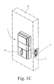
- FIG. 1C is a perspective view of the electronic lock of FIG. 1A as viewed from the interior of the door.
- FIG. 2 is an exploded view of the electronic lock of FIGS. 1A-1C .
- FIG. 3 is a perspective view of the interior chassis of the electronic lock of FIG. 2 , with the upper cover and daughter card removed.
- FIG. 4 is a block diagram of a portion of the electronics circuitry of the interior chassis of FIG. 3 , as it pertains to an embodiment of the present invention.
- FIG. 5 is flowchart depicting a profile selection routine for automatically selecting a wireless protocol profile for use by the electronic lock, in accordance with an embodiment of the present invention.
- an electronic lock in accordance with an embodiment of the present invention for mounting on a door D, and which includes an interior chassis 1 , an exterior chassis 2 , a mounting plate 3 , an adapter 4 , a latch assembly 5 , and a strike 6 .
- latch assembly 5 is of a configuration well known in the art, and includes a bolt actuator mechanism 7 , and a bolt 8 .
- Mounting plate 3 is used to mount the electronic lock to the door D.
- Adapter 4 is used to adapt the electronic lock to a particular hole opening in the door D.
- interior chassis 1 includes the electronics circuitry 9 for the electronic lock, and further includes a manual turnpiece 10 .
- Manual turnpiece 10 is used on the interior side of door D to operate the bolt actuator mechanism 7 of latch assembly 5 , and in turn to extend and retract bolt 8 (see also FIG. 1C ).
- the electronics circuitry 9 includes a base board 11 and a removable daughter card 12 . Depending on the circumstances, the electronics circuitry 9 could be implemented entirely on the base board 11 .
- a removable cover 13 is provided to cover over the base board 11 and daughter card 12 , when cover 13 is in the installed position.
- Daughter card 12 is a wireless communications module that facilitates wireless communications with an external device though a desired wireless communications protocol, e.g., Zigbee, Z-wave, etc.
- exterior chassis 2 includes a keypad 14 for receiving a user input.
- Keypad 14 is electrically connected to the base board 11 of electronics circuitry 9 , such as for example by an electrical cable 15 .
- an electrical motor (not show) is energized to retract the bolt 8 of latch assembly 5 , thus permitting door D (see FIG. 1B ) to be opened from a closed position.
- a key actuator 16 having a removable key K, is provided for manually operating latch assembly 5 from the exterior of the door D.
- daughter card 12 is a wireless communications module that facilitates wireless communications with an external device through a desired wireless communications protocol, e.g., Zigbee, Z-wave, etc.
- base board 11 and/or daughter card 12 of electronics circuitry 9 is configurable to enable automatic selection of an appropriate wireless protocol profile, i.e., a configuration corresponding to a standard wireless protocol or a desired variation of the standard wireless protocol, so as to allow the electronic lock to communicatively join a system into which the electronic lock is being incorporated.
- Electronics circuitry 9 may include, for example, an EMBER Corporation EM357 chip along with associated devices to handle all IEEE 802.15.4 operations. The chip and associated devices is driven by a 24.00 MHz crystal which is used to produce other internal clocks. Additional devices, such as LED's, switches, other integrated circuits, antenna and others are designed into electronics circuitry 9 .
- electronics circuitry 9 includes a processing unit 17 and a memory unit 18 .
- ASIC Application Specific Integrated Circuit
- I/O input/output
- Processing unit 17 is configured such that during a system boot-up process (e.g., at power up) or a designated profile selection event, processing unit 17 automatically uses the appropriate wireless communication protocol profile from a plurality of wireless protocol profiles # 1 -#n stored in memory unit 18 .
- Memory unit 18 is an electronic semiconductor memory device, such as for example, a read only memory (ROM), erasable programmable read only memory (EPROM), electrically erasable programmable read only memory (EEPROM), embedded memory in the processing unit 17 etc. As shown in FIG. 4 , memory unit 18 is configured to store a plurality of wireless protocol profiles # 1 -#n associated with a wireless communication protocol. Each wireless protocol profile stored in memory unit 18 corresponds to a standard wireless protocol or a specific variation of the standard wireless protocol as dictated by the wireless communications system requirements of a respective customer. For example, different implementations of wireless protocols could correspond with different wireless protocol profiles.
- a first manufacturer's implementation of the Zigbee protocol could be a first profile and a second manufacturer's implementation of the Zigbee protocol could be a second profile.
- memory unit 18 may store a plurality of sets of wireless protocol profiles, with each set of wireless protocol profiles being associated with a respective wireless communication protocol.
- the wireless protocol profiles in memory unit 18 may be updated, or new wireless protocol profiles added, by a wired or wireless connection to electronics circuitry 9 from a profile source device, such as a computer.
- processing unit 17 executes program instructions to sequentially and individually retrieve, load and execute in sequential order each of the wireless protocol profiles of the plurality of wireless protocol profiles # 1 -#n stored in memory unit 18 until wireless communication is established with another wireless communication device of the system into which the electronic lock is being integrated.
- FIG. 5 is an exemplary profile selection routine that may be used by electronics circuitry 9 of the electronic lock to automatically select the appropriate wireless communication protocol profile from the plurality of wireless protocol profiles stored in memory unit 18 .
- processing unit 17 checks to see if a profile flag is set.
- the profile flag is an indication as to whether an appropriate wireless protocol profile has been established as a default wireless protocol profile for the electronic lock.
- step S 102 the default wireless protocol profile is already loaded into the executable memory of processing unit 17 , and the process ends.
- step S 104 the “bootloader code” is executed to initialize electronics circuitry 9 to automatically and sequentially scroll through the supported wireless communication protocol profiles stored in memory unit 18 .
- processing unit 17 sequences through the wireless protocol profiles stored in memory unit 18 until communication is established, or until there are no more profiles to check.
- processing unit 17 retrieves a first profile, e.g., wireless protocol profile # 1 , from memory unit 18 . Processing unit 17 then executes the selected wireless protocol profile to configure electronics circuitry 9 for attempted wireless communication with another communication device in the system in which the electronic lock is being installed.
- a first profile e.g., wireless protocol profile # 1
- processing unit 17 executes the selected wireless protocol profile to configure electronics circuitry 9 for attempted wireless communication with another communication device in the system in which the electronic lock is being installed.
- step S 106 If at step S 106 no communication is detected, then at step S 108 it is determined that no wireless protocol profile has been found and processing unit 17 will then re-execute step S 106 and sequentially advance to the next profile, e.g., wireless protocol profile # 2 , and retrieve the next profile, e.g., wireless protocol profile # 2 , from memory unit 18 . Processing unit 17 then executes the selected profile, e.g., wireless protocol profile # 2 , to configure electronics circuitry 9 for attempted communication with another communication device in the system in which the electronic lock is being installed. This process continues until the appropriate wireless protocol profile that facilitates wireless communication with another communication device in the system is established, thus becoming the default wireless protocol profile.
- the next profile e.g., wireless protocol profile # 2
- the electronic lock will indicate an error, e.g., by illuminating an error LED or by an audible sound or both. It could also be setup to repeat the loop until terminated by the users. As it starts a new loop, it provides an indication by illuminating an LED or by an audible sound or both (or using other user interface).
- step S 106 if communications is established with another communication device in the system, then at step S 108 it is determined that the appropriate wireless protocol profile has been found, and will be the default wireless protocol profile. The process proceeds to step S 110 .
- the identified default wireless protocol profile is stored in processor memory of processing unit 17 and loaded for default execution by processing unit 17 .
- processing unit 17 sets the profile flag. From this time on, the electronics circuitry 9 will execute the same default wireless protocol profile.
- step S 102 is again executed and the process ends.
- the wireless protocol profile or an executable program corresponding to the profile is uploaded into the target memory location, e.g., processor memory, of processing unit 17 , for execution.
- the electronic lock will power up with that default setting until certain criteria is met that requires desired protocol configuration verification.
- Such criteria may be, for example, a power loss or movement of the electronic lock to a new location and/or new system.
- An embodiment of the present invention thus enables automatic detection and selection of the desired wireless protocol profile.
- an embodiment of the present invention allows the flexibility to add new wireless protocol profiles on the same electronic lock (EL) unit, i.e., stock keeping unit (SKU), to accommodate the various wireless protocol profile configuration requirements of multiple customers, without having to create new hardware specific to a particular customer, e.g., system provider.
- an embodiment of the present invention provides flexibility during manufacturing of the electronic lock (EL) if and when a new custom wireless protocol profile is required by a customer.
Abstract
Description
Claims (6)
Priority Applications (1)
| Application Number | Priority Date | Filing Date | Title |
|---|---|---|---|
| US14/059,652 US9406181B2 (en) | 2012-10-23 | 2013-10-22 | Electronic lock having software based automatic multi-wireless profile detection and setting |
Applications Claiming Priority (2)
| Application Number | Priority Date | Filing Date | Title |
|---|---|---|---|
| US201261717154P | 2012-10-23 | 2012-10-23 | |
| US14/059,652 US9406181B2 (en) | 2012-10-23 | 2013-10-22 | Electronic lock having software based automatic multi-wireless profile detection and setting |
Publications (2)
| Publication Number | Publication Date |
|---|---|
| US20140109634A1 US20140109634A1 (en) | 2014-04-24 |
| US9406181B2 true US9406181B2 (en) | 2016-08-02 |
Family
ID=49551770
Family Applications (1)
| Application Number | Title | Priority Date | Filing Date |
|---|---|---|---|
| US14/059,652 Active 2034-04-10 US9406181B2 (en) | 2012-10-23 | 2013-10-22 | Electronic lock having software based automatic multi-wireless profile detection and setting |
Country Status (6)
| Country | Link |
|---|---|
| US (1) | US9406181B2 (en) |
| EP (1) | EP2912637B1 (en) |
| KR (1) | KR102206369B1 (en) |
| CA (1) | CA2889008C (en) |
| HK (1) | HK1214392A1 (en) |
| WO (1) | WO2014066395A1 (en) |
Cited By (27)
| Publication number | Priority date | Publication date | Assignee | Title |
|---|---|---|---|---|
| US20160371910A1 (en) * | 2015-06-22 | 2016-12-22 | Schlage Lock Company Llc | Multifunctional access control device |
| US10360748B2 (en) * | 2017-08-14 | 2019-07-23 | Q & K International Group Limited | Method of achieving free-pairing wireless door lock based on DIP switch, a wireless door lock and a communication method for the wireless door lock |
| USD866290S1 (en) * | 2018-04-25 | 2019-11-12 | Schlage Lock Company Llc | Camelot lock interior escutcheon |
| USD867104S1 (en) * | 2016-11-23 | 2019-11-19 | ASSA ABLOY Residential Group, Inc. | Trim ring lock |
| USD869261S1 (en) * | 2018-04-25 | 2019-12-10 | Schlage Lock Company Llc | Century lock interior escutcheon |
| US10544605B2 (en) | 2017-05-19 | 2020-01-28 | Douglas A. Yates | Sliding lockable housing with supplemental openings |
| US10641013B2 (en) | 2016-02-16 | 2020-05-05 | Go Lock Technology, Inc. | Portable lock with integrity sensors |
| USD885865S1 (en) * | 2019-01-16 | 2020-06-02 | SimpliSafe, Inc. | Door lock |
| USD887249S1 (en) * | 2019-01-16 | 2020-06-16 | SimpliSafe, Inc. | Door lock |
| USD887248S1 (en) * | 2019-01-16 | 2020-06-16 | SimpliSafe, Inc. | Door lock |
| USD888537S1 (en) * | 2019-01-16 | 2020-06-30 | SimpliSafe, Inc. | Door lock |
| USD888536S1 (en) * | 2019-01-04 | 2020-06-30 | Schlage Lock Company Llc | Compact electronic lock |
| US10778285B2 (en) | 2017-01-04 | 2020-09-15 | Go Lock Technology, Inc. | Cable with integral sensing elements for fault detection |
| USD896614S1 (en) * | 2019-02-20 | 2020-09-22 | Brainchild Electronic Co., Ltd. | Door lock |
| USD902689S1 (en) * | 2019-01-04 | 2020-11-24 | Spectrum Brands, Inc. | Deadbolt for a door |
| US10952077B1 (en) | 2019-09-30 | 2021-03-16 | Schlage Lock Company Llc | Technologies for access control communications |
| US10968660B2 (en) | 2018-02-28 | 2021-04-06 | Passivebolt, Inc. | Electronic door lock |
| US11002061B1 (en) | 2020-01-04 | 2021-05-11 | Passivebolt, Inc. | Electronic door system |
| USD974871S1 (en) * | 2022-09-29 | 2023-01-10 | Jie Liao | Electronic door lock |
| US11560736B2 (en) | 2020-03-04 | 2023-01-24 | Endura Products, Llc | Method for operating a door and components related to the same |
| USD976673S1 (en) * | 2022-08-15 | 2023-01-31 | Zhongshan Futai Intelligent Security Technology Co., Ltd. | Smart lock |
| USD983012S1 (en) * | 2021-05-31 | 2023-04-11 | Wenzhou Zhexin Intelligent Technology Co., Ltd. | Smart door lock |
| USD983643S1 (en) * | 2021-06-03 | 2023-04-18 | Fengchi Wan | Smart door lock |
| US11639617B1 (en) | 2019-04-03 | 2023-05-02 | The Chamberlain Group Llc | Access control system and method |
| USD991008S1 (en) * | 2023-02-28 | 2023-07-04 | Dongchun Huang | Electronic door lock |
| US11739564B2 (en) | 2020-03-04 | 2023-08-29 | Endura Products, Llc | Method for operating a door and components related to the same |
| US11821236B1 (en) | 2021-07-16 | 2023-11-21 | Apad Access, Inc. | Systems, methods, and devices for electronic dynamic lock assembly |
Families Citing this family (21)
| Publication number | Priority date | Publication date | Assignee | Title |
|---|---|---|---|---|
| US9795214B2 (en) * | 2013-04-19 | 2017-10-24 | Best Lockers, Llc | System and method for retrofitting coin-operated lockers |
| USD787914S1 (en) | 2014-04-21 | 2017-05-30 | Best Lockers, Llc | Coin-operated locker |
| US9562370B2 (en) | 2014-11-21 | 2017-02-07 | Schlage Lock Company Llc | Electromechanical lockset |
| CN104916018A (en) * | 2015-05-28 | 2015-09-16 | 江苏苏南万科物业服务有限公司 | Intelligent barrier gate system |
| CN104916017A (en) * | 2015-05-28 | 2015-09-16 | 江苏苏南万科物业服务有限公司 | Exit intelligent access control system |
| CN104933788A (en) * | 2015-05-28 | 2015-09-23 | 江苏苏南万科物业服务有限公司 | Entrance intelligent access control method |
| CN104933790A (en) * | 2015-05-28 | 2015-09-23 | 江苏苏南万科物业服务有限公司 | Exit intelligent access control method |
| CN104916016A (en) * | 2015-05-28 | 2015-09-16 | 江苏苏南万科物业服务有限公司 | Entrance Intelligent Access Control System |
| CN105469480A (en) * | 2015-11-18 | 2016-04-06 | 广东欧珀移动通信有限公司 | A door lock operating method, a device and a door lock |
| CN105741387A (en) * | 2016-01-22 | 2016-07-06 | 刘思超 | Access control recognition method, access control card, server and access control recognition system |
| CN105957192A (en) * | 2016-04-19 | 2016-09-21 | 南京紫米网络科技有限公司 | Access control system |
| CN106056717A (en) * | 2016-06-16 | 2016-10-26 | 广州地理研究所 | System and method for scanning and verifying codes in offline manner |
| CN106296926B (en) * | 2016-08-16 | 2018-07-20 | 北京智优加网络科技有限公司 | A kind of intelligent entrance guard control system and method based on mandate in limited time |
| CN106652113A (en) * | 2016-09-23 | 2017-05-10 | 北京小米移动软件有限公司 | Access control method and device |
| CN106408714A (en) * | 2016-09-29 | 2017-02-15 | 中国人民解放军海军航空工程学院 | Control method and system of intelligent lock |
| CN106485824A (en) * | 2016-11-18 | 2017-03-08 | 成都雅骏新能源汽车科技股份有限公司 | A kind of method and system of electric automobile remotely control car door lock |
| CN106408674B (en) * | 2016-11-24 | 2019-03-08 | 广州华工信息软件有限公司 | Non-parking charge lane system and its control method and control device |
| CN106600774A (en) * | 2016-12-07 | 2017-04-26 | 深圳市万睿智能科技有限公司 | Face identification gate inhibition control method provided with door opening detection area and system thereof |
| CN106558136A (en) * | 2016-12-08 | 2017-04-05 | 安居慧云(厦门)科技有限公司 | A kind of gate control system for mobile personnel's management |
| US11933092B2 (en) | 2019-08-13 | 2024-03-19 | SimpliSafe, Inc. | Mounting assembly for door lock |
| USD997688S1 (en) * | 2021-05-19 | 2023-09-05 | Nanjing Easthouse Electrical Co., Ltd. | Panel for locks |
Citations (30)
| Publication number | Priority date | Publication date | Assignee | Title |
|---|---|---|---|---|
| US4783638A (en) | 1986-06-13 | 1988-11-08 | Thomson-Csf | Frequency doubling oscillator working at ultra-high frequencies |
| EP0753822A2 (en) | 1995-07-12 | 1997-01-15 | Ilco Unican, Inc. | Transponder detector |
| US5729057A (en) | 1995-07-31 | 1998-03-17 | Siemens Aktiengesellschaft | Vehicle antitheft device using transponder and having illuminated keyhole |
| US5841390A (en) | 1994-07-05 | 1998-11-24 | Tsui; Philip Y. W. | Remote transmitter-receiver controller for multiple systems |
| US6038895A (en) | 1997-06-07 | 2000-03-21 | Kiekert Ag | Electrical self-powered motor-vehicle door latch |
| WO2000065551A1 (en) | 1999-04-24 | 2000-11-02 | Soundcraft, Inc. | Low-power radio frequency identification reader |
| US6209367B1 (en) * | 1997-06-06 | 2001-04-03 | Richard G. Hyatt, Jr. | Electronic cam assembly |
| US6370381B1 (en) * | 1999-01-29 | 2002-04-09 | Siemens Transportation Systems, Inc. | Multiple channel communications system |
| US20030137404A1 (en) | 1999-06-10 | 2003-07-24 | Bonneau Walter C. | Multiple protocol smart card communication device |
| US20030151493A1 (en) | 2002-02-13 | 2003-08-14 | Swisscom Ag | Access control system, access control method and devices suitable therefor |
| US6906612B2 (en) | 2002-04-11 | 2005-06-14 | Lear Corporation | System and method for vehicle passive entry having inside/outside detection |
| US6937140B1 (en) | 1993-07-30 | 2005-08-30 | Ge Interlogix, Inc. | Personal digital assistant key for an electronic lock |
| US6967562B2 (en) | 2002-02-22 | 2005-11-22 | Royal Thoughts, Llc | Electronic lock control and sensor module for a wireless system |
| US20060255909A1 (en) | 2003-01-14 | 2006-11-16 | Frank Pavatich | Security system |
| EP1835436A2 (en) | 2006-03-16 | 2007-09-19 | TeraTron GmbH | Transponder reading device |
| US20070290792A1 (en) | 2006-06-12 | 2007-12-20 | Nissan Motor Co., Ltd. | Door lock mechanism controller and method of controlling door lock mechanism |
| US20080011032A1 (en) | 2006-07-17 | 2008-01-17 | Groff John K | Remotely operable door lock interface system |
| WO2009088901A1 (en) | 2007-12-31 | 2009-07-16 | Schlage Lock Company | Method and system for remotely controlling access to an access point |
| US20090256677A1 (en) | 2008-04-10 | 2009-10-15 | Lear Corporation | Passive entry system and method |
| WO2009158181A1 (en) | 2008-06-27 | 2009-12-30 | Schlage Lock Company | Electronic door lock with modular components |
| WO2010012463A2 (en) | 2008-07-30 | 2010-02-04 | Burg-Wächter Kg | Method for operating a locking system |
| WO2011109005A1 (en) | 2010-03-02 | 2011-09-09 | Utc Fire & Security Corporation | Seamless authentication system |
| US20110234377A1 (en) | 2010-03-23 | 2011-09-29 | Rf Ideas, Inc. | Method and apparatus for identifying an RFID type |
| US20120073338A1 (en) | 2010-09-23 | 2012-03-29 | Dave Mohla | Intelligent Automated Deadbolt |
| US20120157080A1 (en) | 2009-08-05 | 2012-06-21 | Openways Sas | Secure system for programming electronically controlled locking devices by means of encrypted acoustic accreditations |
| US20120196588A1 (en) * | 2010-04-29 | 2012-08-02 | Mehul Jayant Shah | Communication protocol preferences |
| US20120213362A1 (en) | 2009-09-17 | 2012-08-23 | Phoniro Ab | Distribution Of Lock Access Data For Electromechanical Locks In An Access Control System |
| US20130295986A1 (en) * | 2012-05-04 | 2013-11-07 | Intel Mobile Communications GmbH | Communication devices and methods for selecting a radio access mode |
| US20130342314A1 (en) | 2012-06-22 | 2013-12-26 | Gun Chen | Smart lock structure and operating method thereof |
| US20140028438A1 (en) | 2012-07-25 | 2014-01-30 | Utc Fire & Security Corporation | Systems and methods for locking device management |
-
2013
- 2013-10-22 EP EP13786812.1A patent/EP2912637B1/en active Active
- 2013-10-22 KR KR1020157012054A patent/KR102206369B1/en active IP Right Grant
- 2013-10-22 US US14/059,652 patent/US9406181B2/en active Active
- 2013-10-22 CA CA2889008A patent/CA2889008C/en active Active
- 2013-10-22 WO PCT/US2013/066189 patent/WO2014066395A1/en active Application Filing
-
2016
- 2016-02-26 HK HK16102205.9A patent/HK1214392A1/en unknown
Patent Citations (32)
| Publication number | Priority date | Publication date | Assignee | Title |
|---|---|---|---|---|
| US4783638A (en) | 1986-06-13 | 1988-11-08 | Thomson-Csf | Frequency doubling oscillator working at ultra-high frequencies |
| US6937140B1 (en) | 1993-07-30 | 2005-08-30 | Ge Interlogix, Inc. | Personal digital assistant key for an electronic lock |
| US5841390A (en) | 1994-07-05 | 1998-11-24 | Tsui; Philip Y. W. | Remote transmitter-receiver controller for multiple systems |
| EP0753822A2 (en) | 1995-07-12 | 1997-01-15 | Ilco Unican, Inc. | Transponder detector |
| US5739766A (en) * | 1995-07-12 | 1998-04-14 | Ilco Unican Inc. | Transponder detector |
| US5729057A (en) | 1995-07-31 | 1998-03-17 | Siemens Aktiengesellschaft | Vehicle antitheft device using transponder and having illuminated keyhole |
| US6209367B1 (en) * | 1997-06-06 | 2001-04-03 | Richard G. Hyatt, Jr. | Electronic cam assembly |
| US6038895A (en) | 1997-06-07 | 2000-03-21 | Kiekert Ag | Electrical self-powered motor-vehicle door latch |
| US6370381B1 (en) * | 1999-01-29 | 2002-04-09 | Siemens Transportation Systems, Inc. | Multiple channel communications system |
| WO2000065551A1 (en) | 1999-04-24 | 2000-11-02 | Soundcraft, Inc. | Low-power radio frequency identification reader |
| US20030137404A1 (en) | 1999-06-10 | 2003-07-24 | Bonneau Walter C. | Multiple protocol smart card communication device |
| US20030151493A1 (en) | 2002-02-13 | 2003-08-14 | Swisscom Ag | Access control system, access control method and devices suitable therefor |
| US6967562B2 (en) | 2002-02-22 | 2005-11-22 | Royal Thoughts, Llc | Electronic lock control and sensor module for a wireless system |
| US6906612B2 (en) | 2002-04-11 | 2005-06-14 | Lear Corporation | System and method for vehicle passive entry having inside/outside detection |
| US20060255909A1 (en) | 2003-01-14 | 2006-11-16 | Frank Pavatich | Security system |
| EP1835436A2 (en) | 2006-03-16 | 2007-09-19 | TeraTron GmbH | Transponder reading device |
| US20070290792A1 (en) | 2006-06-12 | 2007-12-20 | Nissan Motor Co., Ltd. | Door lock mechanism controller and method of controlling door lock mechanism |
| US20080011032A1 (en) | 2006-07-17 | 2008-01-17 | Groff John K | Remotely operable door lock interface system |
| WO2009088901A1 (en) | 2007-12-31 | 2009-07-16 | Schlage Lock Company | Method and system for remotely controlling access to an access point |
| US20100283579A1 (en) | 2007-12-31 | 2010-11-11 | Schlage Lock Company | Method and system for remotely controlling access to an access point |
| US20090256677A1 (en) | 2008-04-10 | 2009-10-15 | Lear Corporation | Passive entry system and method |
| WO2009158181A1 (en) | 2008-06-27 | 2009-12-30 | Schlage Lock Company | Electronic door lock with modular components |
| WO2010012463A2 (en) | 2008-07-30 | 2010-02-04 | Burg-Wächter Kg | Method for operating a locking system |
| US20120157080A1 (en) | 2009-08-05 | 2012-06-21 | Openways Sas | Secure system for programming electronically controlled locking devices by means of encrypted acoustic accreditations |
| US20120213362A1 (en) | 2009-09-17 | 2012-08-23 | Phoniro Ab | Distribution Of Lock Access Data For Electromechanical Locks In An Access Control System |
| WO2011109005A1 (en) | 2010-03-02 | 2011-09-09 | Utc Fire & Security Corporation | Seamless authentication system |
| US20110234377A1 (en) | 2010-03-23 | 2011-09-29 | Rf Ideas, Inc. | Method and apparatus for identifying an RFID type |
| US20120196588A1 (en) * | 2010-04-29 | 2012-08-02 | Mehul Jayant Shah | Communication protocol preferences |
| US20120073338A1 (en) | 2010-09-23 | 2012-03-29 | Dave Mohla | Intelligent Automated Deadbolt |
| US20130295986A1 (en) * | 2012-05-04 | 2013-11-07 | Intel Mobile Communications GmbH | Communication devices and methods for selecting a radio access mode |
| US20130342314A1 (en) | 2012-06-22 | 2013-12-26 | Gun Chen | Smart lock structure and operating method thereof |
| US20140028438A1 (en) | 2012-07-25 | 2014-01-30 | Utc Fire & Security Corporation | Systems and methods for locking device management |
Non-Patent Citations (4)
| Title |
|---|
| International Search Report; Patent Cooperation Treaty; Apr. 10, 2014; PCT/US2013/74291. |
| International Search Report; Patent Cooperation Treaty; Feb. 19, 2014; PCT/US2013/66816. |
| International Search Report; Patent Cooperation Treaty; Feb. 6, 2014. |
| USPTO; Office Action; U.S. Appl. No. 14/059,625; Aug. 27, 2015. |
Cited By (33)
| Publication number | Priority date | Publication date | Assignee | Title |
|---|---|---|---|---|
| US9792747B2 (en) * | 2015-06-22 | 2017-10-17 | Allegion, Inc. | Multifunctional access control device |
| US20180040184A1 (en) * | 2015-06-22 | 2018-02-08 | Schlage Lock Company Llc | Multifunctional access control device |
| US10083560B2 (en) * | 2015-06-22 | 2018-09-25 | Schlage Lock Company Llc | Multifunctional access control device |
| US10311664B2 (en) * | 2015-06-22 | 2019-06-04 | Schlage Lock Company Llc | Multifunctional access control device |
| US20160371910A1 (en) * | 2015-06-22 | 2016-12-22 | Schlage Lock Company Llc | Multifunctional access control device |
| US11879273B2 (en) | 2016-02-16 | 2024-01-23 | Go Lock Technology, Inc. | Portable lock with integrity sensors |
| US10641013B2 (en) | 2016-02-16 | 2020-05-05 | Go Lock Technology, Inc. | Portable lock with integrity sensors |
| USD867104S1 (en) * | 2016-11-23 | 2019-11-19 | ASSA ABLOY Residential Group, Inc. | Trim ring lock |
| US10778285B2 (en) | 2017-01-04 | 2020-09-15 | Go Lock Technology, Inc. | Cable with integral sensing elements for fault detection |
| US10544605B2 (en) | 2017-05-19 | 2020-01-28 | Douglas A. Yates | Sliding lockable housing with supplemental openings |
| US10360748B2 (en) * | 2017-08-14 | 2019-07-23 | Q & K International Group Limited | Method of achieving free-pairing wireless door lock based on DIP switch, a wireless door lock and a communication method for the wireless door lock |
| US10968660B2 (en) | 2018-02-28 | 2021-04-06 | Passivebolt, Inc. | Electronic door lock |
| USD869261S1 (en) * | 2018-04-25 | 2019-12-10 | Schlage Lock Company Llc | Century lock interior escutcheon |
| USD866290S1 (en) * | 2018-04-25 | 2019-11-12 | Schlage Lock Company Llc | Camelot lock interior escutcheon |
| USD888536S1 (en) * | 2019-01-04 | 2020-06-30 | Schlage Lock Company Llc | Compact electronic lock |
| USD902689S1 (en) * | 2019-01-04 | 2020-11-24 | Spectrum Brands, Inc. | Deadbolt for a door |
| USD888537S1 (en) * | 2019-01-16 | 2020-06-30 | SimpliSafe, Inc. | Door lock |
| USD887249S1 (en) * | 2019-01-16 | 2020-06-16 | SimpliSafe, Inc. | Door lock |
| USD885865S1 (en) * | 2019-01-16 | 2020-06-02 | SimpliSafe, Inc. | Door lock |
| USD887248S1 (en) * | 2019-01-16 | 2020-06-16 | SimpliSafe, Inc. | Door lock |
| USD896614S1 (en) * | 2019-02-20 | 2020-09-22 | Brainchild Electronic Co., Ltd. | Door lock |
| US11639617B1 (en) | 2019-04-03 | 2023-05-02 | The Chamberlain Group Llc | Access control system and method |
| US10952077B1 (en) | 2019-09-30 | 2021-03-16 | Schlage Lock Company Llc | Technologies for access control communications |
| US11800359B2 (en) | 2019-09-30 | 2023-10-24 | Schlage Lock Company Llc | Technologies for access control communications |
| US11002061B1 (en) | 2020-01-04 | 2021-05-11 | Passivebolt, Inc. | Electronic door system |
| US11560736B2 (en) | 2020-03-04 | 2023-01-24 | Endura Products, Llc | Method for operating a door and components related to the same |
| US11739564B2 (en) | 2020-03-04 | 2023-08-29 | Endura Products, Llc | Method for operating a door and components related to the same |
| USD983012S1 (en) * | 2021-05-31 | 2023-04-11 | Wenzhou Zhexin Intelligent Technology Co., Ltd. | Smart door lock |
| USD983643S1 (en) * | 2021-06-03 | 2023-04-18 | Fengchi Wan | Smart door lock |
| US11821236B1 (en) | 2021-07-16 | 2023-11-21 | Apad Access, Inc. | Systems, methods, and devices for electronic dynamic lock assembly |
| USD976673S1 (en) * | 2022-08-15 | 2023-01-31 | Zhongshan Futai Intelligent Security Technology Co., Ltd. | Smart lock |
| USD974871S1 (en) * | 2022-09-29 | 2023-01-10 | Jie Liao | Electronic door lock |
| USD991008S1 (en) * | 2023-02-28 | 2023-07-04 | Dongchun Huang | Electronic door lock |
Also Published As
| Publication number | Publication date |
|---|---|
| HK1214392A1 (en) | 2016-07-22 |
| WO2014066395A1 (en) | 2014-05-01 |
| EP2912637B1 (en) | 2021-12-08 |
| EP2912637A1 (en) | 2015-09-02 |
| KR102206369B1 (en) | 2021-01-22 |
| CA2889008C (en) | 2021-01-19 |
| US20140109634A1 (en) | 2014-04-24 |
| CA2889008A1 (en) | 2014-05-01 |
| KR20150077435A (en) | 2015-07-07 |
Similar Documents
| Publication | Publication Date | Title |
|---|---|---|
| US9406181B2 (en) | Electronic lock having software based automatic multi-wireless profile detection and setting | |
| US11060323B2 (en) | Electronic lock having hardware based multi-wireless profile detection and setting | |
| US9390572B2 (en) | Electronic lock having a mobile device user interface | |
| US9691207B2 (en) | Electronic lock with user interface | |
| US10083560B2 (en) | Multifunctional access control device | |
| US9967151B2 (en) | Secure remote actuation system | |
| US20150091704A1 (en) | Method and System for Initiating a Function in an Electronic Device | |
| US20160254946A1 (en) | Discovering, identifying, and configuring devices with opaque addresses in the internet of things environment | |
| CN107444340A (en) | Wireless communication system | |
| US20150317170A1 (en) | Modular electronics board and methods of configuring and operating the same | |
| DE102014210000A1 (en) | Local operation of devices of an installation bus | |
| JP7122623B2 (en) | Communication device and communication system | |
| US20200264314A1 (en) | Systems and methods for obtaining a location of an appliance | |
| CN112204994B (en) | Unified control device and unified control system | |
| KR20160110761A (en) | Method for registering multiple remote controllers into a receiver | |
| CN107433446A (en) | It is anti-to load in mixture device and method | |
| KR20130142547A (en) | Apparatus and method thereof initialing lighting system information | |
| WO2015048166A1 (en) | A method and system for initiating a function in an electronic device | |
| ES1138007U (en) | Module for access control (Machine-translation by Google Translate, not legally binding) |
Legal Events
| Date | Code | Title | Description |
|---|---|---|---|
| AS | Assignment |
Owner name: KWIKSET CORPORATION, CALIFORNIA Free format text: ASSIGNMENT OF ASSIGNORS INTEREST;ASSIGNORS:ALMOMANI, NEDAL AKRAM;MARIDAKIS, MICHAEL;REEL/FRAME:031849/0904 Effective date: 20131223 |
|
| AS | Assignment |
Owner name: WELLS FARGO BANK, NATIONAL ASSOCIATION, GEORGIA Free format text: SECURITY INTEREST;ASSIGNORS:SPECTRUM BRANDS, INC.;UNITED PET GROUP, INC.;KWIKSET CORPORATION;AND OTHERS;REEL/FRAME:032874/0109 Effective date: 20140430 |
|
| AS | Assignment |
Owner name: APPLICA CONSUMER PRODUCTS, INC., A CORP. OF FLORIDA, FLORIDA Free format text: RELEASE BY SECURED PARTY;ASSIGNOR:WELLS FARGO BANK, NATIONAL ASSOCIATION, AS COLLATERAL TRUSTEE;REEL/FRAME:036102/0001 Effective date: 20150623 Owner name: SPECTRUM BRANDS, INC. AS SUCCESSOR IN INTEREST TO ROVCAL, INC., WISCONSIN Free format text: RELEASE BY SECURED PARTY;ASSIGNOR:WELLS FARGO BANK, NATIONAL ASSOCIATION, AS COLLATERAL TRUSTEE;REEL/FRAME:036102/0001 Effective date: 20150623 Owner name: SPECTRUM BRANDS, INC., A CORP. OF DELAWARE, WISCONSIN Free format text: RELEASE BY SECURED PARTY;ASSIGNOR:WELLS FARGO BANK, NATIONAL ASSOCIATION, AS COLLATERAL TRUSTEE;REEL/FRAME:036102/0001 Effective date: 20150623 Owner name: TETRA HOLDING (US), INC., A CORP. OF DELAWARE, VIRGINIA Free format text: RELEASE BY SECURED PARTY;ASSIGNOR:WELLS FARGO BANK, NATIONAL ASSOCIATION, AS COLLATERAL TRUSTEE;REEL/FRAME:036102/0001 Effective date: 20150623 Owner name: UNITED INDUSTRIES CORPORATION AS SUCCESSOR IN INTEREST TO LIQUID HOLDING COMPANY, INC., MISSOURI Free format text: RELEASE BY SECURED PARTY;ASSIGNOR:WELLS FARGO BANK, NATIONAL ASSOCIATION, AS COLLATERAL TRUSTEE;REEL/FRAME:036102/0001 Effective date: 20150623 Owner name: UNITED PET GROUP, INC., A CORP. OF DELAWARE, WISCONSIN Free format text: RELEASE BY SECURED PARTY;ASSIGNOR:WELLS FARGO BANK, NATIONAL ASSOCIATION, AS COLLATERAL TRUSTEE;REEL/FRAME:036102/0001 Effective date: 20150623 Owner name: ROVCAL, INC., WISCONSIN Free format text: RELEASE BY SECURED PARTY;ASSIGNOR:WELLS FARGO BANK, NATIONAL ASSOCIATION, AS COLLATERAL TRUSTEE;REEL/FRAME:036102/0001 Effective date: 20150623 Owner name: ROV HOLDING, INC., A CORP. OF DELAWARE, DELAWARE Free format text: RELEASE BY SECURED PARTY;ASSIGNOR:WELLS FARGO BANK, NATIONAL ASSOCIATION, AS COLLATERAL TRUSTEE;REEL/FRAME:036102/0001 Effective date: 20150623 Owner name: RUSSELL HOBBS, INC., A CORP. OF DELAWARE, ILLINOIS Free format text: RELEASE BY SECURED PARTY;ASSIGNOR:WELLS FARGO BANK, NATIONAL ASSOCIATION, AS COLLATERAL TRUSTEE;REEL/FRAME:036102/0001 Effective date: 20150623 Owner name: SEED RESOURCES, L.L.C., MICHIGAN Free format text: RELEASE BY SECURED PARTY;ASSIGNOR:WELLS FARGO BANK, NATIONAL ASSOCIATION, AS COLLATERAL TRUSTEE;REEL/FRAME:036102/0001 Effective date: 20150623 Owner name: ROVCAL, INC., A CORP. OF CALIFORNIA, WISCONSIN Free format text: RELEASE BY SECURED PARTY;ASSIGNOR:WELLS FARGO BANK, NATIONAL ASSOCIATION, AS COLLATERAL TRUSTEE;REEL/FRAME:036102/0001 Effective date: 20150623 Owner name: LIQUID HOLDING COMPANY, INC., PENNSYLVANIA Free format text: RELEASE BY SECURED PARTY;ASSIGNOR:WELLS FARGO BANK, NATIONAL ASSOCIATION, AS COLLATERAL TRUSTEE;REEL/FRAME:036102/0001 Effective date: 20150623 Owner name: NATIONAL MANUFACTURING CO., CALIFORNIA Free format text: RELEASE BY SECURED PARTY;ASSIGNOR:WELLS FARGO BANK, NATIONAL ASSOCIATION, AS COLLATERAL TRUSTEE;REEL/FRAME:036102/0001 Effective date: 20150623 Owner name: APPLICA CONSUMER PRODUCTS, INC., A CORP. OF FLORID Free format text: RELEASE BY SECURED PARTY;ASSIGNOR:WELLS FARGO BANK, NATIONAL ASSOCIATION, AS COLLATERAL TRUSTEE;REEL/FRAME:036102/0001 Effective date: 20150623 Owner name: UNITED PET GROUP, INC., WISCONSIN Free format text: RELEASE BY SECURED PARTY;ASSIGNOR:WELLS FARGO BANK, NATIONAL ASSOCIATION, AS COLLATERAL TRUSTEE;REEL/FRAME:036102/0001 Effective date: 20150623 Owner name: SALIX ANIMAL HEALTH, LLC, FLORIDA Free format text: RELEASE BY SECURED PARTY;ASSIGNOR:WELLS FARGO BANK, NATIONAL ASSOCIATION, AS COLLATERAL TRUSTEE;REEL/FRAME:036102/0001 Effective date: 20150623 Owner name: TETRA HOLDINGS (US), INC., VIRGINIA Free format text: RELEASE BY SECURED PARTY;ASSIGNOR:WELLS FARGO BANK, NATIONAL ASSOCIATION, AS COLLATERAL TRUSTEE;REEL/FRAME:036102/0001 Effective date: 20150623 Owner name: TETRA HOLDING (US), INC., A CORP. OF DELAWARE, VIR Free format text: RELEASE BY SECURED PARTY;ASSIGNOR:WELLS FARGO BANK, NATIONAL ASSOCIATION, AS COLLATERAL TRUSTEE;REEL/FRAME:036102/0001 Effective date: 20150623 Owner name: SPECTRUM BRANDS, INC., A CORP. OF DELAWARE, WISCON Free format text: RELEASE BY SECURED PARTY;ASSIGNOR:WELLS FARGO BANK, NATIONAL ASSOCIATION, AS COLLATERAL TRUSTEE;REEL/FRAME:036102/0001 Effective date: 20150623 Owner name: KWIKSET CORPORATION, CALIFORNIA Free format text: RELEASE BY SECURED PARTY;ASSIGNOR:WELLS FARGO BANK, NATIONAL ASSOCIATION, AS COLLATERAL TRUSTEE;REEL/FRAME:036102/0001 Effective date: 20150623 Owner name: TELL MANUFACTURING, INC., PENNSYLVANIA Free format text: RELEASE BY SECURED PARTY;ASSIGNOR:WELLS FARGO BANK, NATIONAL ASSOCIATION, AS COLLATERAL TRUSTEE;REEL/FRAME:036102/0001 Effective date: 20150623 Owner name: APPLICA CONSUMER PRODUCTS, INC., FLORIDA Free format text: RELEASE BY SECURED PARTY;ASSIGNOR:WELLS FARGO BANK, NATIONAL ASSOCIATION, AS COLLATERAL TRUSTEE;REEL/FRAME:036102/0001 Effective date: 20150623 Owner name: UNITED PET GROUP, INC., A CORP. OF DELAWARE, WISCO Free format text: RELEASE BY SECURED PARTY;ASSIGNOR:WELLS FARGO BANK, NATIONAL ASSOCIATION, AS COLLATERAL TRUSTEE;REEL/FRAME:036102/0001 Effective date: 20150623 Owner name: SPECTRUM BRANDS, INC., WISCONSIN Free format text: RELEASE BY SECURED PARTY;ASSIGNOR:WELLS FARGO BANK, NATIONAL ASSOCIATION, AS COLLATERAL TRUSTEE;REEL/FRAME:036102/0001 Effective date: 20150623 Owner name: SPECTRUM BRANDS, INC. AS SUCCESSOR IN INTEREST TO Free format text: RELEASE BY SECURED PARTY;ASSIGNOR:WELLS FARGO BANK, NATIONAL ASSOCIATION, AS COLLATERAL TRUSTEE;REEL/FRAME:036102/0001 Effective date: 20150623 Owner name: UNITED INDUSTRIES CORPORATION AS SUCCESSOR IN INTE Free format text: RELEASE BY SECURED PARTY;ASSIGNOR:WELLS FARGO BANK, NATIONAL ASSOCIATION, AS COLLATERAL TRUSTEE;REEL/FRAME:036102/0001 Effective date: 20150623 Owner name: PRICE PFISTER, INC., CALIFORNIA Free format text: RELEASE BY SECURED PARTY;ASSIGNOR:WELLS FARGO BANK, NATIONAL ASSOCIATION, AS COLLATERAL TRUSTEE;REEL/FRAME:036102/0001 Effective date: 20150623 Owner name: UNITED INDUSTRIES CORPORATION, MISSOURI Free format text: RELEASE BY SECURED PARTY;ASSIGNOR:WELLS FARGO BANK, NATIONAL ASSOCIATION, AS COLLATERAL TRUSTEE;REEL/FRAME:036102/0001 Effective date: 20150623 |
|
| AS | Assignment |
Owner name: DEUTSCHE BANK AG NEW YORK BRANCH, AS COLLATERAL AGENT, NEW YORK Free format text: SECURITY INTEREST;ASSIGNOR:SPECTRUM BRANDS, INC.;REEL/FRAME:036131/0272 Effective date: 20150623 Owner name: DEUTSCHE BANK AG NEW YORK BRANCH, AS COLLATERAL AG Free format text: SECURITY INTEREST;ASSIGNOR:SPECTRUM BRANDS, INC.;REEL/FRAME:036131/0272 Effective date: 20150623 |
|
| AS | Assignment |
Owner name: SPECTRUM BRANDS, INC., WISCONSIN Free format text: MERGER;ASSIGNOR:KWIKSET CORPORATION;REEL/FRAME:039116/0293 Effective date: 20141104 |
|
| STCF | Information on status: patent grant |
Free format text: PATENTED CASE |
|
| AS | Assignment |
Owner name: ROYAL BANK OF CANADA, ONTARIO Free format text: NOTICE OF SUCCESSOR AGENT AND ASSIGNMENT OF SECURITY INTEREST (INTELLECTUAL PROPERTY) REEL/FRAME 036131/0272;ASSIGNOR:DEUTSCHE BANK AG NEW YORK BRANCH;REEL/FRAME:046301/0425 Effective date: 20180601 |
|
| MAFP | Maintenance fee payment |
Free format text: PAYMENT OF MAINTENANCE FEE, 4TH YEAR, LARGE ENTITY (ORIGINAL EVENT CODE: M1551); ENTITY STATUS OF PATENT OWNER: LARGE ENTITY Year of fee payment: 4 |
|
| AS | Assignment |
Owner name: SPECTRUM BRANDS, INC., WISCONSIN Free format text: RELEASE BY SECURED PARTY;ASSIGNOR:ROYAL BANK OF CANADA;REEL/FRAME:064029/0313 Effective date: 20230620 |
|
| AS | Assignment |
Owner name: ASSA ABLOY AMERICAS RESIDENTIAL INC., CONNECTICUT Free format text: ASSIGNMENT OF ASSIGNORS INTEREST;ASSIGNOR:SPECTRUM BRANDS, INC.;REEL/FRAME:065658/0105 Effective date: 20230620 |
|
| MAFP | Maintenance fee payment |
Free format text: PAYMENT OF MAINTENANCE FEE, 8TH YEAR, LARGE ENTITY (ORIGINAL EVENT CODE: M1552); ENTITY STATUS OF PATENT OWNER: LARGE ENTITY Year of fee payment: 8 |