BENEFIT CLAIM
The present application claims the benefit of U.S. Provisional Patent Application Ser. No. 61/716,656 filed Oct. 22, 2012, entitled “Apparatus for Analytical Sampling and/or Conditioning of a Process Gas with Selective Isolation Capability, and method Therefore”, listing Valmond Joseph St Amant, III and Steven Douglas Calverley as inventors.
BACKGROUND OF THE INVENTION
It is common practice to use sampling probes and the like to extract fluid samples from pressurized pipelines or the like for analysis in the field or for off-site, laboratory analysis. This especially true in the natural gas industry, where the monetary value of the gas is dependent on its compositional analysis. Likewise, the chemical and oil refining industries also have needs for extracting fluid samples from pressurized fluid sources.
Recent offshore pipeline safety concerns since the 2010 Deepwater Horizon offshore incident have renewed an emphasis on the need for isolation devices such as double block and bleed sample valves, as well as compliance with OSHA standards in such activities. The use of an emergency valve shutoff in an isolation device is not believed compatible with the use of conventional sample probes situated as passing through the isolation device (i.e., with the valve in an open position), as said sample probes would be required to be manually or automatically removed to allow for valve closure. Accordingly, since the removal cannot be assured to occur in a timely fashion in an emergency, such an arrangement could not be relied as it may prevent the valve closure in an emergency event, resulting in failure of the emergency shutoff.
Current isolation device technology such as double block and bleed valves use a hollow tube “quill” below the valve as an option for sampling or injection through the open valve, but this system has not shown, suggested, or contemplated the mounting of analytical sample conditioning components or the like therein, and retaining same with the valve in a closed position. Thus, in the prior art, the quill is simply a hollow tube formed to act as a pass-through to facilitate the removal or injection of a sample, and no receiver or retainer function is contemplated.
GENERAL SUMMARY OF THE INVENTION
In an improvement over the prior art, as embodied in the present invention, a quill is formed to receive a component(s) such as a conditioning component or the like, in the vicinity of (upstream) the isolation device, so that the isolation device (valve) may be closed in an emergency with no interference from said conditioning component(s).
In effect, the present invention provides a redesign of the quill for the novel use as a means to receive and retain the component, a probe which is on the pressurized process gas side of the isolation device, and a probe which may be isolated on demand and without delay, should the need arise.
The component(s) utilized in the present device may comprise, for example, sample conditioning components such as membrane separators (e.g., phase separation membrane) regulators and regulator components, isokinetic sampling components, coalescing filters, particulate filters (screens, sintered metal, sintered plastics, thermoplastics, borosilicate glass, etc.), inertial separators, valves (i.e., throttling, needle, metering, ball, switching, etc) and others, and could be provided in a single component housing, or stacked for serial flow therethrough (see for example, FIG. 4A-4E).
The term “conditioning component” is not intended to be limiting as similar components may likewise be used in the present invention, including sensors and monitoring components such as corrosion coupons, wireless monitoring devices such as thermometers, wireless monitoring devices, moisture sensors, gas sensors (e.g. H2S and others), etc.
BRIEF DESCRIPTION OF THE FIGURES
For a further understanding of the nature and object of the present invention, reference should be had to the following detailed description, taken in conjunction with the accompanying drawings, in which like parts are given like reference numbers or letters, and wherein:
FIG. 1 is a side, partially cut-away view of the first, preferred embodiment of the present invention, illustrating a quill 17 engaged to an isolation device/valve 1, the quill 17 forming a receiver to receive cartridge 16 having sample conditioning component 11 situated therein to receive flow from longitudinal passage 12.
FIG. 2A is a side, partially cut-away, close-up view of the quill 17 of FIG. 1 engaging flange 4.
FIG. 2B is a side view of the cartridge 16 of FIG. 1.
FIG. 2C is a side, partially cut-away, close up view of the sample conditioning component in the cartridge in the quill of FIG. 1.
FIG. 2D is a bottom, view of the quill end of FIG. 1 distal the mounting flange.
FIG. 3A is a side view of the quill with mounting flange of FIG. 2A.
FIG. 3B is a side view of a cartridge of the present invention.
FIG. 3C is a side view of the quill of FIG. 3A showing the cartridge in phantom.
FIG. 3D is a downstream (top) end view of the cartridge of FIG. 3B.
FIG. 4A is a side, perspective view of a second, alternative embodiment of the quill of the present invention designed to engage a cartridge containing one, or multiple stacked conditioning components therein.
FIG. 4B is a side view of the modular, stackable cartridge of FIG. 4A.
FIG. 4C is a downstream (upper) end view of the modular, stackable cartridge of FIG. 4A.
FIG. 4D is an upstream (lower) end view of the modular, stackable cartridge of FIG. 4A.
FIG. 4E is another side, perspective view of the modular, stackable cartridge of FIG. 4A.
FIG. 5A is a side, perspective view of the modular, stackable cartridge of FIG. 3B.
FIG. 5B is an upstream (top) end view of the cartridge of FIG. 5A.
FIG. 5C is a side view of the cartridge of FIG. 5A showing the inner chamber for receiving a modular sampling conditioning component in phantom.
FIG. 5D is another side, perspective view of the modular, stackable cartridge of FIG. 5A.
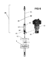
FIG. 6 is a side view illustrating the insertion/removal tool of the present invention positioned to pass through and isolation device/valve to access/engage a cartridge/modular conditioning component situated in a quill.
FIG. 7 is a side view of an insertion/removal tool of the present invention positioned to engage a double block and bleed (DBB) type valve to access the quill downstream for insertion/removal and/or maintenance of a cartridge/modular sample conditioning component therein.
FIG. 7A is a close-up view of a hex drive with spring-biased ball indent formed to engage the cartridge containing the modular sample conditioning component(s).
FIG. 7B is a side, partially cut-away view of a flange having a quill mounted thereto having a cartridge with modular sample conditioning component mounted thereto.
FIG. 8A is a side view of the insertion/removal tool of the present invention, showing a close-up of the upper portion of the tool including the button to manually engage the hex drive with spring-biased ball indent on the opposing end of the tool to the cartridge containing the modular sample conditioning component(s).
FIG. 8B is a side view of the insertion/removal tool of FIG. 8A passing through the double block & bleed valve (in open position) engaging a cartridge containing the conditioning component(s) situated in the quill.
FIG. 8C is a side view of the slotted threaded end of the insertion removal tool associated with the operation of the top button.
FIG. 9 is a side close-up, exploded view of the hex drive with spring-biased ball indent of FIG. 7A.
FIG. 9A is a side, close up, line drawing view of the hex drive body without the spring biased ball indent shown.
FIG. 9B is a bottom view of the body of FIG. 9A.
FIG. 9C is a top view of the body of FIG. 9A.
FIG. 9D is a side, isometric view of the hex drive body with spring biased indent of FIG. 7A.
FIG. 9E is a side view of an insertion/removal tool of the present invention having the hex drive with spring-biased ball indent shown in FIGS. 9-9D.
DETAILED DESCRIPTION OF THE INVENTION
Referring to FIGS. 1, 2A-2D, 3A-3D, and 5A-5E, the first, preferred embodiment of the present invention contemplates a quill 17 having first 3 and second ends 3′ with a passage 12 formed longitudinally therethrough forming a receiver 9 configured to receive a housing or cartridge 16 therein, the cartridge in the present embodiment having first 2 and second 2′ ends, the first end 2 having an outer diameter 10′ (OD) having a threaded area 8, formed to threadingly engage a thread 13 situated within the inner diameter (ID) receiver 9, associated with the OD 10 of quill 17, the cartridge sealingly engageable the ID of the receiver so as to facilitate a longitudinal fluid flow passage 12, 12′ therethrough, the installed cartridge thus forming a “pass-through” for fluids flowing through the quill 17 allowing the conditioning and/or monitoring of same, or alternatively providing a capture device to capture fluids, as will be further discussed infra.
Socket 15 (shown in an exemplary hexagonal configuration shown in FIG. 5A-5B) may be formed in the threaded 8 end 2 of the cartridge 16, to facilitate placement 18 of the cartridge into the quill (FIG. 1), as will be further explained infra. An o-ring 14 or the like about the OD of the cartridge 16 may be used to form a fluid tight seal with the ID of quill when situated therein, such that fluid under pressure will be prevented from flowing between the OD of the installed cartridge and the ID of the surrounding quill, so as to facilitate the flowing of fluid into the quill into the cartridge. The fluid may then be sampled, monitored, or conditioned or otherwise treated and allowed to “pass-through”, depending upon the desired application.
As mentioned, component 11 may comprise a single component which may be single function or multifunction, or alternatively may comprise one or more modular components 11′ “stacked” (either within a common cartridge or one or more stacked cartridges in the receiver) in series in fluid sealed fashion so as to allow the contained flow of fluid therethrough so as to condition same, or have other features such as monitoring, sampling, or the like (FIG. 2A).
Thus, the present installation allows a flow-through, when desired, of fluid flowing from the process gas stream 47 associated with the main. Accordingly, if component 11 comprises a conditioning component, with the valve 1 in an open position, fluid from the main flows 25 from the main 47, through any intermediary lateral, through the quill 17, into the cartridge 16, and through conditioning component(s) 11 situated therein, conditioning same so as to provide conditioned gas, for selective flow through valve 1 or vent 27 (FIG. 7).
This “flow through” feature may also be useful in a monitoring capacity, such as a corrosion coupon or the like. If no flow-through is desired, the downstream valve need only be closed, or alternatively, the cartridge 16 may not have a passage through the first 2 end, or the component may only have an opening at the end associated with the second end 2′ of cartridge.
Alternatively, if the component is for sampling such as fluid collection, or monitoring such as pressure, temperature, liquids, etc, flow-through as a feature may or may not be utilized.
Further, if a monitoring component is utilized in lieu or in conjunction with a conditioning component, the fluid is being monitored upstream the valve, it thus may provide a monitoring of the gas on the process stream 47 side of the isolation device, even where said device is closed.
FIGS. 6-9, taken in conjunction with FIGS. 1-3 and 5, illustrate a new and innovative system utilizing a specially designed tool and method of use to facilitate access to cartridge (and thus any component 11 therein) via valve 1, and thus allow component 11 to be serviceable, installable, and/or removable without the need for removal/dismantling of the valve/isolation device or the like, or otherwise significantly interrupting the operation of the system.
As shown, the system of the present invention is formed so as to allow a tool to be inserted thru the open valve or other passage to allow access to the quill for insertion/removal of the cartridge 16, as well as offering the ability to inspect, maintain, replace, install the cartridge with component therein below/upstream the valve, even while the pipeline is still pressurized.
Referring to FIGS. 6-8, the insertion/removal tool 30 of the present invention comprises a length of threaded rod 31 having first 32 and second 32′ ends (FIG. 7), said rod having a longitudinal passage 33 formed therethrough, so as to provide a passage having an opening at each of said opposing ends 32, 32′.
Situated within said longitudinal passage 33 of said threaded rod 31 is a control rod 52 having first 53 and second 53′ ends and a length which is longitudinally adjustable relative to rod 31, as will be more fully discussed herein.
Said second end 32′ of said threaded rod 31 has formed at its longitudinal passage 33 a cavity 55 formed to slidingly receive and support a drive 34 (for example, a square or hexagonal profile, see FIG. 7A), which engages said control rod 52 (in phantom) at its second end 53′, so that said drive 34 can be selectively be manually retracted 45′ or extended 44′ by rotating hex nut 46 associated with the first 53 end of said control rod, which hex nut 46 engages a threaded area on said hex adapter 36, providing a mechanical advantage so as to allow the longitudinally repositioning of said control rod, thereby causing said drive 34 to retract 45′ into, or extend 44′ from said cavity, respectively. When the drive 34 slidingly engages the enveloping cavity at the second end 32′ of rod, it is designed so that the cavity limits axial rotation of the drive to that of the threaded rod 31, so that when drive 34 slidingly engages the enveloping cavity at the second end 32′ of rod, the axial rotation of the rod 31 rotates drive 34.
Continuing with the drawings, body 37 is provided having first 38 and second 38′ ends, said body having a threaded longitudinal passage 39 formed therethrough to threadingly engage said threaded rod 31, said first 38 end of said body having a sealing nut 51 associated therewith for selectively providing sealing force on the packing gland 54, therewith making a seal on threaded rod 31, said second end of said body further comprising a profile 48 (for example, square profile with corner fillets) so that a wrench or the like may engage same, and a threaded end 40, formed to engage a threaded socket in an opening 41 associated with a threaded opening of a valve 1 (FIG. 1), or as shown beginning FIG. 7, an opening 41′ of a isolation device/double block and bleed (DBB) valve. As shown, the body also includes a receiver 56 passage at the second 38′ end to receive a cartridge 16, as will be further discussed herein.
Referring to the figures, for an exemplary use of the insertion/retrieval system of the present invention with a double block and bleed (DBB) valve 1′, a quill 17 having a receiver 9 formed therein must be first mounted upstream the DBB. Generally, this installation will include an initial component, for example, a sample conditioning component 11 in a cartridge 16, threadingly seated in the receiver 9. Once the quill 17 installation is complete, the system can be serviced and maintained without the need for pressure shutdown, as will be shown, below.
Referring to FIGS. 7-8B, in a scenario where the component needs to be removed from the system using the insertion/retrieval tool, first valves 42, 42′ are closed and the pressure within the valve is vented via the vent 27 passage therebetween. Cap 50, if any, is then removed from the opening to the valve.
Threaded end 40 of body then is positioned to engage threaded socket opening 41 (FIG. 6) of the opening of the valve 1 (or in DBB, opening 41′, FIG. 7). The body of the tool is then threadingly engaged to the threaded socket opening 41 to form a sealed engagement by tightening body via profile 48.
After confirming the vent 27 on the DBB valve 1′ is closed, 42, 42′ can now be opened and the pressure contained as the threaded end 40 of body engaging threaded socket opening 41′ of the DBB valve forms a plug. With the insertion/retrieval tool 30 in place and the valves opened, there is now provided a clear passageway to the quill 17 and any component therein.
To lower 44′ the second end 32′ of threaded rod to facilitate engagement to cartridge 16 already in the quill 17, the hex adapter 36 is turned 43, so as to lower the threaded rod 31 into the valve, through the valve passage and open valves 42, 42′, until the second end 32′ of the threaded rod with drive 34 is in the vicinity of the cartridge.
To cause drive 34 to emerge 44′ from the second end 32′ of threaded rod so as to engage socket 15 of cartridge 16, hex nut 46 is turned, urging 44 control rod 52 toward the DBB valve 1, causing drive 34 to extend 44′ from the tool, through the open valve, until it extends into the locked position so as to engage socket 15 of cartridge 16, and biased ball 35 of drive 34 engages an indent formed in the sidewall of socket 15, to releasably engage same. Knob 49 may be provided so as to allow an operator to manually position drive 34 axially by turning control rod 52 (FIG. 8A) via knob 49, so as to align drive 34 with socket 15 so that drive 34 may be further lowered to engage socket 15 with the second end 32′ of threaded rod engaging drive.
Once drive 34 has engaged socket, hex adapter 36 is rotated 43′ in reverse direction, raising the rod while rotating drive 34 engaging socket 15, rotating cartridge 16, thereby disengaging threaded end 8 of cartridge from threaded portion 13 of quill receiver, urging cartridge 16 through quill then through the open valve(s) or isolation device, to the second end 32′ of tool 30.
Once the cartridge 16 is drawn into to the second end 32′ of body 37 of the tool 30, the cartridge and threaded rod should be clear the outer valve opening 41 (41′ of the DBB valve/isolation device), said outer valve 42′ is then closed and any residual gas between the closed outer valve 42 and the second end 38′ of tool 30 is vented via the vent 27. At that point, the profile 48 on the body 37 can be turned 43′ to disengage the threaded engagement between the threaded end 40 of body 37 and threaded socket at the opening 41′ on the DBB valve/isolation device (or opening 41 in a regular valve as in FIG. 6), and the tool with cartridge removed.
While the above example illustrated removal of a cartridge in the quill, the same procedure may be used to insert and install the cartridge into the quill, utilizing a similar variation of the above procedure, but with some of the steps in reverse.
Referring to FIGS. 4A-4E and 1, in a second embodiment of the present invention, a component (for example, modular sample conditioning component or the like) is mounted to engage a quill situated on the process gas pressure side of the isolation device or valve. Such a system may comprise, for example, a fixed installation wherein the sampling component is fixedly attached to the component, thus without ready means for installation, maintenance, or removal other than shutting the system down and depressurizing the pipeline.
Alternatively, a quill 2 may be provided to removeably engage the component, for example, via threaded connection, but not necessarily accessible from outside the installation. For example, the component might threadingly engaging the end 3′ of the quill distal the end 3 of the quill 2, which is threaded to threadingly engage a threaded OD in flange 4 (FIG. 1). See FIG. 4A-4E.
ELEMENTS of the INVENTION
- 1 isolation device/valve
- 2 quill
- 3, 3′ first, second ends
- 4 mounting flange
- 8 threaded end
- 9 receiver
- 10, 10′ inner, outer diameters
- 11 sample conditioning component,'
- 12 longitudinal passage
- 13 threaded portion
- O′ring or other seal
- 15 socket for receiving tool
- 16 cartridge
- 17 quill
- 25 flow
- 26 threaded end
- 27 vent
- 30 insertion/retrieval tool
- 31 threaded rod
- 32, 32′ first, second ends
- 33 longitudinal passage therethrough
- 34 Drive
- 35 spring biased ball indent
- 36 hex adapter
- 37 body
- 38 first, second ends
- 39 threaded longitudinal passage therethrough
- 40 threaded end
- 41 opening (threaded socket)
- 42,′ levers for operating of isolation device/DBB valve
- 43 rotate in first direction, second direction
- 44 lower, emanate
- 45 raise, retract
- 46 nut to lower drive to engage socket 15
- 47 process gas stream
- 48 profile on body for engaging valve
- 49 button
- 50 plug
- 51 sealing nut
- 52 control rod
- 54 packing gland
- 55 cavity
- 56 receiver
The invention embodiments herein described are done so in detail for exemplary purposes only, and may be subject to many different variations in design, structure, application and operation methodology. Thus, the detailed disclosures therein should be interpreted in an illustrative, exemplary manner, and not in a limited sense.