US9420952B2 - Temperature probe suitable for axillary reading - Google Patents

Temperature probe suitable for axillary reading Download PDF

Info

Publication number
US9420952B2
US9420952B2 US12/844,775 US84477510A US9420952B2 US 9420952 B2 US9420952 B2 US 9420952B2 US 84477510 A US84477510 A US 84477510A US 9420952 B2 US9420952 B2 US 9420952B2
Authority
US
United States
Prior art keywords
temperature
axilla
person
temperature sensing
patient
Prior art date
Legal status (The legal status is an assumption and is not a legal conclusion. Google has not performed a legal analysis and makes no representation as to the accuracy of the status listed.)
Active, expires
Application number
US12/844,775
Other versions
US20120029310A1 (en
Inventor
Pierre PAQUET
Binta DIALLO
Mark Raptis
Current Assignee (The listed assignees may be inaccurate. Google has not performed a legal analysis and makes no representation or warranty as to the accuracy of the list.)
CareFusion 303 Inc
Original Assignee
CareFusion 303 Inc
Priority date (The priority date is an assumption and is not a legal conclusion. Google has not performed a legal analysis and makes no representation as to the accuracy of the date listed.)
Filing date
Publication date
Application filed by CareFusion 303 Inc filed Critical CareFusion 303 Inc
Priority to US12/844,775 priority Critical patent/US9420952B2/en
Assigned to CAREFUSION 303, INC. reassignment CAREFUSION 303, INC. ASSIGNMENT OF ASSIGNORS INTEREST (SEE DOCUMENT FOR DETAILS). Assignors: PAQUET, PIERRE, DIALLO, BINTA, RAPTIS, MARK
Priority to PCT/US2011/045256 priority patent/WO2012015767A2/en
Publication of US20120029310A1 publication Critical patent/US20120029310A1/en
Application granted granted Critical
Publication of US9420952B2 publication Critical patent/US9420952B2/en
Active legal-status Critical Current
Adjusted expiration legal-status Critical

Links

Images

Classifications

    • AHUMAN NECESSITIES
    • A61MEDICAL OR VETERINARY SCIENCE; HYGIENE
    • A61BDIAGNOSIS; SURGERY; IDENTIFICATION
    • A61B5/00Measuring for diagnostic purposes; Identification of persons
    • A61B5/0002Remote monitoring of patients using telemetry, e.g. transmission of vital signals via a communication network
    • A61B5/0004Remote monitoring of patients using telemetry, e.g. transmission of vital signals via a communication network characterised by the type of physiological signal transmitted
    • A61B5/0008Temperature signals
    • AHUMAN NECESSITIES
    • A61MEDICAL OR VETERINARY SCIENCE; HYGIENE
    • A61BDIAGNOSIS; SURGERY; IDENTIFICATION
    • A61B5/00Measuring for diagnostic purposes; Identification of persons
    • A61B5/01Measuring temperature of body parts ; Diagnostic temperature sensing, e.g. for malignant or inflamed tissue
    • AHUMAN NECESSITIES
    • A61MEDICAL OR VETERINARY SCIENCE; HYGIENE
    • A61BDIAGNOSIS; SURGERY; IDENTIFICATION
    • A61B5/00Measuring for diagnostic purposes; Identification of persons
    • A61B5/02Detecting, measuring or recording pulse, heart rate, blood pressure or blood flow; Combined pulse/heart-rate/blood pressure determination; Evaluating a cardiovascular condition not otherwise provided for, e.g. using combinations of techniques provided for in this group with electrocardiography or electroauscultation; Heart catheters for measuring blood pressure
    • A61B5/0205Simultaneously evaluating both cardiovascular conditions and different types of body conditions, e.g. heart and respiratory condition
    • A61B5/02055Simultaneously evaluating both cardiovascular condition and temperature
    • AHUMAN NECESSITIES
    • A61MEDICAL OR VETERINARY SCIENCE; HYGIENE
    • A61BDIAGNOSIS; SURGERY; IDENTIFICATION
    • A61B2562/00Details of sensors; Constructional details of sensor housings or probes; Accessories for sensors
    • A61B2562/02Details of sensors specially adapted for in-vivo measurements
    • A61B2562/0271Thermal or temperature sensors
    • AHUMAN NECESSITIES
    • A61MEDICAL OR VETERINARY SCIENCE; HYGIENE
    • A61BDIAGNOSIS; SURGERY; IDENTIFICATION
    • A61B5/00Measuring for diagnostic purposes; Identification of persons
    • A61B5/68Arrangements of detecting, measuring or recording means, e.g. sensors, in relation to patient
    • A61B5/6801Arrangements of detecting, measuring or recording means, e.g. sensors, in relation to patient specially adapted to be attached to or worn on the body surface
    • A61B5/6813Specially adapted to be attached to a specific body part
    • AHUMAN NECESSITIES
    • A61MEDICAL OR VETERINARY SCIENCE; HYGIENE
    • A61BDIAGNOSIS; SURGERY; IDENTIFICATION
    • A61B5/00Measuring for diagnostic purposes; Identification of persons
    • A61B5/68Arrangements of detecting, measuring or recording means, e.g. sensors, in relation to patient
    • A61B5/6801Arrangements of detecting, measuring or recording means, e.g. sensors, in relation to patient specially adapted to be attached to or worn on the body surface
    • A61B5/683Means for maintaining contact with the body
    • A61B5/6832Means for maintaining contact with the body using adhesives
    • A61B5/6833Adhesive patches

Definitions

  • the present disclosure generally relates to systems and methods of physiological monitoring, and, in particular, relates to a temperature probe suitable for axillary reading.
  • a temperature probe for axillary temperature reading of a person can comprise a sensing portion configured for placement within the axilla of a person and having a first end and a second end.
  • the sending portion can comprise a temperature sensing element configured to provide a signal responsive to a change in body temperature of the person.
  • the temperature probe can further comprise a wiring portion having one end connected to the first end of the sensing portion and comprising an electrical conductor, the electrical conductor having a first end configured for coupling to a monitoring device, and a second end connected to the temperature sensing element, the electrical connector configured to carry the signal from the temperature sensing element to the monitoring device.
  • the temperature probe can further comprise a body connection portion having one end connected to the second end of the sensing portion and configured to be attached to another body portion of the person.
  • FIG. 2A is a perspective view of the vitals sign monitor patch shown in FIG. 1 according to certain aspects of the present disclosure.
  • FIG. 3B is a functional schematic diagram of an embodiment of the surveillance server according to certain aspects of the present disclosure.
  • heart rate monitor Widely sold for use in exercise and physical training, heart rate monitors may comprise a torso band in which are embedded two electrodes held against the skin and a small electronics package. Such heart rate monitors can communicate wirelessly to other equipment such as a small device that is worn like a wristwatch and that can transfer data wirelessly to a personal computer (PC).
  • PC personal computer
  • the monitor patch 20 may engage in direct wireless communication with the server 60 .
  • the server 60 itself or a wireless modem connected to the server 60 may include a wireless communication system to receive data from the monitor patch 20 .
  • the term ‘hermetic’ implies that the rate of transmission of moisture through the seal is substantially the same as through the material of the layers that are sealed to each other, and further implies that the size of particulates that can pass through the seal are below the size that can have a significant effect on circuit assembly 24 .
  • Flexible conductive circuit 26 passes through portions of sealing areas 29 and the seal between layers 23 and 27 is maintained by sealing of layers 23 and 27 to flexible circuit assembly 28 .
  • the layers 23 and 27 are thin and flexible, as is the flexible conductive circuit 26 , allowing the side segment 22 of the monitor patch 20 between the electrodes 28 and the circuit assembly 24 to bend as shown in FIG. 2A .
  • the processor 202 is also capable of communication with the receiver 206 and the transmitter 209 of the wireless transceiver 207 via the bus 204 .
  • the processor 202 using the transmitter and receiver 209 , 206 can transmit and receive data to and from the bridge 40 .
  • the transmitter 209 includes one or more of a RF signal generator (e.g., an oscillator), a modulator (a mixer), and a transmitting antenna; and the receiver 206 includes a demodulator (a mixer) and a receiving antenna which may or may not be the same as the transmitting antenna.
  • the transmitter 209 may include a digital-to-analog converter configured to receive data from the processor 202 and to generate a base signal; and/or the receiver 206 may include an analog-to-digital converter configured to digitize a demodulated base signal and output a stream of digitized data to the processor 202 .
  • the processor 202 may include a general-purpose processor or a specific-purpose processor for executing instructions and may further include a memory 219 , such as a volatile or non-volatile memory, for storing data and/or instructions for software programs.
  • the instructions which may be stored in a memory 219 and/or 210 , may be executed by the processor 202 to control and manage the wireless transceiver 207 , the sensor interfaces 212 , 214 , 216 , as well as provide other communication and processing functions.
  • the processor 202 may be a general-purpose microprocessor, a microcontroller, a Digital Signal Processor (DSP), an Application Specific Integrated Circuit (ASIC), a Field Programmable Gate Array (FPGA), a Programmable Logic Device (PLD), a controller, a state machine, gated logic, discrete hardware components, or any other suitable device or a combination of devices that can perform calculations or other manipulations of information.
  • DSP Digital Signal Processor
  • ASIC Application Specific Integrated Circuit
  • FPGA Field Programmable Gate Array
  • PLD Programmable Logic Device
  • controller a state machine, gated logic, discrete hardware components, or any other suitable device or a combination of devices that can perform calculations or other manipulations of information.
  • Information such as program instructions, data representative of sensor readings, preset alarm conditions, threshold limits, may be stored in a computer or processor readable medium such as a memory internal to the processor 202 (e.g., the memory 219 ) or a memory external to the processor 202 (e.g., the memory 210 ), such as a Random Access Memory (RAM), a flash memory, a Read Only Memory (ROM), a Programmable Read-Only Memory (PROM), an Erasable PROM (EPROM), registers, a hard disk, a removable disk, or any other suitable storage device.
  • RAM Random Access Memory
  • ROM Read Only Memory
  • PROM Erasable PROM
  • registers a hard disk, a removable disk, or any other suitable storage device.
  • the internal sensor 236 can be one or more sensors configured to measure certain properties of the processing and sensor interface module 201 , such as a board temperature sensor thermally coupled to a PCB. In other embodiments, the internal sensor 236 can be one or more sensors configured to measure certain properties of the patient 10 , such as a motion sensor (e.g., an accelerometer) for measuring the patient's motion or position with respect to gravity.
  • a motion sensor e.g., an accelerometer
  • the external sensors 232 , 234 can include sensors and sensing arrangements that are configured to produce a signal representative of one or more vital signs of the patient to which the monitor patch 20 is attached.
  • the first external sensor 232 can be a set of sensing electrodes that are affixed to an exterior surface of the monitor patch 20 and configured to be in contact with the patient for measuring the patient's respiratory rate
  • the second external sensor 234 can include a temperature sensing element (e.g., a thermocouple or a thermistor or resistive thermal device (RTD)) affixed, either directly or via an interposing layer, to skin of the patient 10 for measuring the patient's body temperature.
  • one or more of the external sensors 232 , 234 or one or more additional external sensors can measure other vital signs of the patient, such as blood pressure, pulse rate, or oxygen saturation.
  • FIG. 3A is a functional block diagram illustrating exemplary electronic components of bridge 40 of FIG. 1 according to one aspect of the subject disclosure.
  • Bridge 40 includes a processor 310 , radio 320 having a receiver 322 and a transmitter 324 , radio 330 having a receiver 332 and a transmitter 334 , memory 340 , display 345 , and network interface 350 having a wireless interface 352 and a wired interface 354 .
  • some or all of the aforementioned components of module 300 may be integrated into single devices or mounted on PCBs.
  • transmitters 324 and 334 may include a digital-to-analog converter configured to convert data received from processor 310 and to generate a base signal, while receivers 322 and 332 may include analog-to-digital converters configured to convert a demodulated base signal and sent a digitized data stream to processor 310 .
  • Processor 310 may be a general-purpose microprocessor, a microcontroller, a Digital Signal Processor (DSP), an Application Specific Integrated Circuit (ASIC), a Field Programmable Gate Array (FPGA), a Programmable Logic Device (PLD), a controller, a state machine, gated logic, discrete hardware components, or any other suitable device or a combination of devices that can perform calculations or other manipulations of information.
  • DSP Digital Signal Processor
  • ASIC Application Specific Integrated Circuit
  • FPGA Field Programmable Gate Array
  • PLD Programmable Logic Device
  • controller a state machine, gated logic, discrete hardware components, or any other suitable device or a combination of devices that can perform calculations or other manipulations of information.
  • RAM Random Access Memory
  • ROM Read Only Memory
  • PROM Programmable Read Only Memory
  • EPROM Erasable Programmable Read Only Memory
  • registers a hard disk, a removable disk, a Solid State Memory (SSD), or any other suitable storage device.
  • Memory 312 or 340 can also store a list or a database of established communication links and their corresponding characteristics (e.g., signal levels) between the bridge 40 and its related monitor patches 20 .
  • the memory 340 external to the processor 310 includes such a database 342 ; alternatively, the memory 312 internal to the processor 310 may include such a database.
  • RAM Random Access Memory
  • ROM Read Only Memory
  • PROM Programmable Read Only Memory
  • EPROM Erasable Programmable Read Only Memory
  • registers a hard disk, a removable disk, a Solid State Memory (SSD), or any other suitable storage device.
  • Memory 362 or 370 can also store a database of communication links and their corresponding characteristics (e.g., signal levels) between monitor patches 20 and bridges 40 .
  • the memory 370 external to the processor 360 includes such a database 372 ; alternatively, the memory 362 internal to the processor 360 may include such a database.
  • the monitor patch 20 are configured to operate with external sensors that are in turn configured to produce a signal representative of one or more vital signs of the patient to whom the monitor patch 20 is attached.
  • the second external sensor 234 can be a temperature probe that includes a temperature sensing element (e.g., a thermocouple or thermistor) affixed, either directly or via an interposing layer, to skin of the patient 10 for measuring the patient's body temperature.
  • FIG. 4A is a diagram depicting a patient 10 wearing a temperature monitoring system 20 A comprising a monitor patch 20 and a temperature probe 400 that is configured to measure body temperature of the patient 10 .
  • the temperature probe 400 is configured for axillary temperature sensing of the patient 10 to whom the monitor patch 20 is attached.
  • the monitor patch 20 is attached to the chest 11 of the patient 10 , with a sensing portion of the temperature probe 400 retained in the axilla 12 of the patient 10 during body temperature monitoring.
  • FIG. 4B is a diagram providing an enlarged view of the monitoring system 20 A depicted in FIG. 4A according to certain aspects of the present disclosure.
  • the monitor patch 20 is attached to the chest 11 of the patient 10 via, e.g., an adhesive backing (not shown).
  • the temperature probe 400 has a proximal end 401 and a distal end 403 and includes a wiring portion 410 , a body connection portion 430 B, and a sensing portion 420 disposed between the wiring and body connection portions 410 , 430 B.
  • the proximal end 401 of the temperature probe 400 is connected to the monitor patch 20 at its connection port 22 .
  • the proximal end 401 of the temperature probe 400 is removably attached (e.g., plugged) to the monitor patch 20 .
  • the proximal end 401 is fixedly attached (e.g., epoxied or fused) to the monitor patch 20 .
  • the sensing portion 420 of the temperature probe 400 is configured for placement within the axilla 12 of the patient 10 and includes a temperature sensing element (e.g., 234 A-D of FIGS. 5A-D and 234 E-F of FIGS. 6A-B ).
  • the wiring portion 410 of the temperature probe 400 includes one or more electrical conductors ( 512 , 514 of FIGS. 5A-D and FIGS. 6A-B ) for carrying a signal responsive to a change in body temperature of the patient 10 between the temperature sensing element 234 and the monitor patch 20 .
  • the monitoring system 20 A further includes an adhesive element 416 (e.g., a tape) coupled to the cable between the first and second coiled sections 414 , 418 and configured to attach the wiring portion 410 of the cable to the patient's body, e.g., at a point between the chest 11 and the armpit 12 of the patient.
  • an adhesive element 416 e.g., a tape
  • the body connection portion 430 B has one end connected to the sensing portion 420 and is configured to be attached to another body portion of the patient 10 such that the sensing portion 420 of the temperature probe 400 can be retained within the axilla 12 of the patient 10 .
  • such attachment is achieved via an adhesive element 426 (e.g., a tape) coupled to the distal end of the body connection portion 430 B.
  • the coupled adhesive element 426 is then attached to a second body portion 13 (e.g., the back of the patient's arm) of the patient 10 .
  • a second body portion 13 e.g., the back of the patient's arm
  • FIG. 4C is a diagram providing an enlarged view of an alternative monitoring system 20 B according to certain aspects of the present disclosure.
  • the monitoring system 20 B is substantially the same as the monitoring system 20 A, except an additional (e.g., third) coiled section 419 is provided in body connection portion 430 C in place of the elastic tubing 430 B.
  • the additional coiled section 419 can provide all or some of the pulling force such as the one provided by the elastic tubing in the embodiment of FIG. 4B .
  • the coiled section 419 acts as a spring.
  • the remainder of the body connection portion 430 C may include an elastic or inelastic flexible tubing.
  • the body connection portion 430 of the temperature probe 400 can include one or more coiled sections similar to the coiled section 414 of the wiring portion 410 . Any or all of the coiled sections 414 , 418 , 419 in the embodiments of FIGS. 4B and 4C may be replaced with elastic elements (e.g., elastic tubing).
  • the adhesive element 416 may be coupled to the body connection portion 430 at a point different than the distal end of the body connection portion 430 . In certain embodiments, entirely different means of attaching the body connection portion 430 to the patient's body may be used.
  • the body connection portion 430 may itself be in the form of an adhesive tape that can stick to the body of the patient 10 or may include an elastic loop (e.g., a rubber band) to be placed around the patient's arm.
  • the temperature probe 400 in the illustrated embodiments of FIGS. 4A-C is shown to be operatively coupled to a vital-sign monitor patch worn by the patient 10
  • the temperature probe 400 may be alternatively operatively coupled to other types of monitoring devices such as a stationary monitoring unit located near the patient's hospital bed.
  • a stationary monitoring unit can take readings of the patient's body temperature based on a signal from the temperature probe 400 and send the temperature readings to a surveillance server via a wired or wireless connection and make other decisions such as providing an indication of an alarm condition (e.g., a high body temperature condition or a loss of thermal contact between the temperature probe and the patient).
  • an alarm condition e.g., a high body temperature condition or a loss of thermal contact between the temperature probe and the patient.
  • FIGS. 5A-D are diagrams depicting various exemplary embodiments of the temperature probe according to alternative aspects of the present disclosure. For the purposes of illustration only, without an intent to limit the scope of the present disclosure in any way, the embodiments will be described with references to elements of FIG. 4B . For clarity, each of the diagrams focuses on a region 500 A-D (corresponding to region 500 in FIG. 4B ) of the thermocouple 400 where sensing portion 420 A-D interfaces with wiring portion 410 A-D and body connection portions 430 A-D. The figures are not drawn to scale.
  • the body connection portion 430 D comprises a flexible tape 432 D that is mechanically connected (e.g., glued or fused) to the sensing portion 420 D at the temperature sensing element 234 D and/or an end portion of the first flexible cable 401 D.
  • the flexible tape 432 D includes an adhesive section that can be attached to a body portion (e.g., the back of the patient's arm) so as to retain the sensing portion 420 D of the temperature probe 400 within the axilla 12 of the patient 10 .
  • a signal representative of the voltage difference produced at the junction 601 of the thermocouple 234 E is received by the sensor interface 214 E via the first and second electrical conductors 512 , 514 in the wiring portion 410 E.
  • the sensor interface 214 E includes an amplifier 620 E, an analog-to-digital converter (ADC) 630 E and a current source 605 .
  • the current source 605 supplies a constant DC current that flows through the junction and produces a signal representative of the voltage difference across the junction.
  • the signal is received at the minus input of the amplifier 620 E.
  • the received signal is amplified by the amplifier 620 E, and the amplified signal is received by the ADC 630 E at input port 632 E.
  • the temperature sensing element 234 F includes a thermistor 603 , a type of resistor whose resistance varies with temperature.
  • the thermistor 603 can be made from a material that has a positive temperature coefficient (PTC) (called a “PTC thermistor”) or from a material that has a negative temperature coefficient (NTC) (called a “NTC thermistor”).
  • PTC positive temperature coefficient
  • NTC negative temperature coefficient
  • the sensor interface circuit 214 F includes a Wheatstone bridge 610 F having three fixed resistors (R 1 , R 2 , and R 3 ), an amplifier 620 F, and an analog-to-digital converter (ADC) 630 F.
  • the thermistor 603 functions as a fourth and variable resistor in the Wheatstone bridge 610 F such that the bridge 610 F outputs a signal that is responsive to a change in the resistance of the thermistor 603 , which resistance is in turn responsive to a change in the body temperature of the patient 10 .
  • the signal generated at the Wheatstone bridge 610 is received by an amplifier 620 F.
  • An amplified signal at the output of the amplifier 620 F is received by an input port 632 F of the ADC 630 F.
  • the ADC 630 F digitizes the received signal and provides a stream of digitized data at output port 634 F.
  • the stream of digitized data is passed to a processor (e.g., 202 of FIG. 2 ) for further processing and/or transmission to a surveillance server (e.g., 60 of FIG. 1 ).
  • a processor e.g., 202 of FIG. 2
  • a surveillance server e.g., 60 of FIG. 1
  • the ADC 630 F at its control data input port 636 F receives a set of control data that configures one or more functionalities of the ADC 630 F including, not limited to its sampling (digitization) rate and dynamic range.
  • the monitor patch 20 worn by the patient 10 receives a signal from a temperature sensing element (e.g., a thermocouple and a thermistor) of the temperature probe 400 , the signal responsive to a change in body temperature of the patient 10 .
  • the signal is amplified and digitized into a stream of data by the sensor interface circuit 214 as explained above with respect to FIGS. 6A-B .
  • the digitized signal is then received by the processor 202 .
  • the processor 202 generates a sequence of temperature readings based on the digitized signal.
  • the processor 202 is operatively connected to a wireless communication system (e.g., the wireless transceiver 207 ) which transmits data indicative of the patient's body temperature to the surveillance server 60 via the bridge 40 .
  • a wireless communication system e.g., the wireless transceiver 207
  • the processor 202 performs a number of temperature monitoring functions on the temperature readings to determine, inter alia, a high temperature condition and occurrence and loss of thermal contact between the patient 10 and the temperature probe 400 .
  • FIG. 7 is a graph 700 of a measured temperature reading (T) versus time (t) for illustrating an exemplary temperature monitoring scheme according to certain aspects of the present disclosure.
  • the graph 700 shows a low temperature limit (T L ) and a high temperature limit (T H ) that are used in the temperature monitoring scheme.
  • T L low temperature limit
  • T H high temperature limit
  • the exemplary temperature monitoring scheme will be described with reference to elements of FIGS. 4A ,B.
  • a processor (the processor 202 of FIG.
  • the monitoring device e.g., the monitor patch 20
  • the recognition can be achieved from the temperature reading rising sharply past the low temperature limit (T L ) at a rate exceeding a first threshold rate of rise after having been below T L at least once.
  • the temperature reading begins to rise, indicating that the patient's body temperature is on the rise.
  • the temperature reading exceeds the high temperature limit (T H ).
  • the processor executing control software in the monitoring device can invoke a high temperature handler routine in the control software and take a number of predetermined actions. For example, the processor can cause the transmitter 209 ( FIG. 2 ) to start sending a signal indicative of the high temperature alarm condition to the surveillance server 60 either directly or via the bridge 40 .
  • the surveillance server 60 can send a notification to a hospital system (e.g., the workstation 100 of FIG. 1 ).
  • the monitor patch 20 can also set off an alarm, e.g., at the monitor patch 20 or at a stand alone monitoring unit or at a hospital system (e.g., the workstation 100 of FIG. 1 ), thereby notifying a nurse or other caregiver.
  • the monitor patch 20 can enter into an alert operation mode from the normal operation mode and take and transmit the temperature readings (e.g., to the surveillance server 60 ) at a faster rate. For instance, the monitor patch 20 can take and transmit the temperature reading every 10 minutes during the normal operation mode, but does so every 2 minutes in the alert operation mode.
  • the temperature monitoring scheme utilizes two high temperature limits (T H1 and T H2 , where T H2 >T H1 ) and different sets of predetermined actions are performed depending on whether the temperature reading has exceeded only T H1 or both T H1 and T H2 .
  • the body-probe contact is lost due to, e.g., the patient 10 opening the arm in a manner that causes the sensing portion 420 of the temperature probe 400 to be detached from the axilla 12 of the patient 10 , or the temperature probe 400 accidentally falls off the patient's body.
  • the loss of body-probe contact causes the temperature reading to fall towards a lower (e.g., open-air) value at a relatively sharp rate of decline.
  • the processor executing control software in the monitor patch 20 can detect the loss of body-probe contact by computing a rate of decline in the sequence of temperature readings and comparing the computed rate of decline to a threshold rate of decline.
  • the processor determines that the body-probe contact has been lost and generates an indication of the loss of contact.
  • an indication of the loss of contact is wirelessly transmitted to the bridge 40 to be sent to the surveillance server 60 , and the surveillance server 60 then provides a notification of the loss of contact to a hospital system (e.g., the workstation 100 of FIG. 1 ).
  • the monitor patch 20 itself may sound an alarm indicating the loss of contact to the patient 10 or a nurse or caregiver who is near the patient 10 .
  • the monitor patch 20 after providing the indication, enters a sleep mode in which no additional temperature readings are taken. Alternatively, the monitor patch 20 can continue to take additional temperature readings to determine whether a new body-probe contact has been established.
  • FIG. 8A is diagram depicting a realistic temperature reading (T) versus time (t) graph 800 A associated with a temperature monitoring system (e.g., 20) according to certain aspects of the present disclosure.
  • the temperature readings have peaks (e.g., 811 , 812 ) and valleys (e.g., 854 , 855 ).
  • the up-and-down fluctuations in the temperature readings can be caused by movements of a patient's arm (up and down/back and forth), for example. This is because arm movements can affect the quality of thermal contact between the sensing portion 420 of the temperature probe 400 and the axilla 12 of the patient 10 .
  • the rise may be attributable to a transition from a relatively poor thermal contact to a good thermal contact, e.g., by armpit closing.
  • the decrease may be attributable to a transition from a relatively good thermal contact to a poor thermal contact caused, e.g., by armpit opening up or the temperature probe being detached from the patient 10 , thereby partially or fully exposing the sensing portion 420 to ambient air.
  • a reading taken while the quality of thermal contact is poor is likely to be inaccurate, and thus it is desirable to identify occurrence of such a poor thermal contact so that inaccurate readings associated with the poor thermal contact may be rejected, and only valid temperature readings associated with a good thermal contact are reported, e.g., to the surveillance server 60 .
  • a prolonged loss of thermal contact may be detected and reported so that the patient 10 and/or a caregiver can be alerted.
  • the term “poor thermal contact” refers to partial or complete loss of contact between a temperature probe and a person to whom the temperature probe is supposed to be attached.
  • the monitoring system 20 achieves these objectives by adopting the following principles:
  • T NEW a current (new) temperature reading
  • T MAX the current maximum temperature reading
  • the process 900 loops back to the operation 910 in which another T NEW reading is generated.
  • the process 900 proceeds to operation 930 in which the new temperature reading (T NEW ) is reported, and to operation 940 in which the T NEW reading is assigned to T MAX .
  • a first temperature reading 851 is taken at time 801 , e.g., after an initial attachment of the temperature probe 400 to the patient 10 , and an initial stabilization is determined to be completed at reading 811 .
  • the process 900 proceeds to decision states 970 in which a first query is made as to whether the new temperature reading corresponds to a peak (e.g., local maximum) or a plateau (e.g., relatively flat region after a local maximum), and, if so, a second query is made as to whether the peak/plateau satisfies the gradient condition, namely, whether the peak/plateau is at or above a corresponding one of the threshold decay curves 841 - 849 representing the threshold decay rate (e.g., ⁇ 2 C/h).
  • a first query is made as to whether the new temperature reading corresponds to a peak (e.g., local maximum) or a plateau (e.g., relatively flat region after a local maximum)
  • a second query is made as to whether the peak/plateau satisfies the gradient condition, namely, whether the peak/plateau is at or above a corresponding one of the threshold decay curves 841 - 849 representing the threshold decay rate (e.g., ⁇ 2
  • the first and second queries of the decision state 970 are designed to determine whether the current T NEW reading satisfies Condition 3.
  • the first query relating to the occurrence of a peak/plateau involves obtaining a sequence of temperature readings and retroactively identifying one of the readings corresponding to a local maximum. If the first and second queries of the decision state 970 are both satisfied (YES), the process 900 loops back to the operations 930 and 940 in which the current T NEW reading is reported and assigned to T MAX .
  • the process 900 proceeds to another decision state 980 in which a query is made as to whether a maximum duration for the current T MAX reading has been exceeded.
  • This query detects a prolonged loss of thermal contact between the temperature probe 420 and the axilla 12 of the patient 10 .
  • the maximum duration is preset at a value between about 10 and 30 minutes. If the query at the decision state 980 is NO (maximum duration not exceeded), the process 900 loops back to the operation 950 where another temperature reading is generated and then to decision state 960 and potentially to decision state 970 where Conditions 2 and 3, respectively, are checked.
  • the algorithm maintains the current T MAX reading, and the monitoring system 20 considers it as the currently effective temperature reading as indicated by the line 831 .
  • the process 900 proceeds to operation 990 in which the loss of thermal contact is reported (e.g., displayed on hospital system 100 ) and then back to operations 950 , where a next T NEW reading is taken.
  • temperature readings (e.g., 852 , 853 ) generated after the reading 811 do not satisfy the combination of first and second queries of the decision state 970 , and the maximum duration for the current T MAX reading is exceeded at t 2 .
  • the monitoring system 20 at or after t 2 reports the prolonged loss of thermal contact to, e.g., a database in the surveillance server 60 or the patient 10 and/or nurse/caregiver at operation 990 . After the reporting at operation 990 , the process 900 loops back to the operations 950 , where a next T NEW reading is taken.
  • the process 900 After determining (e.g., identifying) the initially-stabilized T NEW reading 812 , the process 900 detects a series of new peak temperature readings 813 - 819 that satisfies Condition 2 ( 813 , 817 , 819 ) or Condition 3 ( 814 , 815 , 816 , 818 ). Other T NEW readings, such as readings 852 , 853 , 856 , however, are rejected because they do not satisfy either Condition 2 (T NEW not greater than the current T MAX 815 ) or Condition 3 (T NEW below the threshold decay curve 845 ). Valid temperature readings do not always have to be local maxima. For example, after identifying the reading 812 , the algorithm associated with the process 900 can report a series of readings between t 4 and t 5 indicated by the curved line 832 as they satisfy Condition 2.
  • certain aspects of various temperature monitoring algorithms described herein are performed by the processor 202 ( FIG. 2C ) executing one or more sequences of one or more instructions using threshold limits contained in an internal machine-readable medium such as the internal memory 219 or the memory 210 .
  • the processor 202 can determine the loss of body-probe thermal contact by executing instructions contained in the internal memory 202 that involve computation of a rate of decline in temperature readings and comparison of the rate of decline to a threshold rate of decline stored in the memory 210 or generation of a threshold decay curve 841 - 849 based on a threshold decay rate and comparison of the current T NEW reading to the threshold decay curve.
  • the processor 202 may be a microprocessor, a microcontroller, a digital signal processor (DSP), or an application specific integrated circuit (ASIC) capable of executing computer instructions. Such instructions and/or threshold limits may be read into the memory 219 , 210 from another machine-readable medium, such as a CD, flash memory, or a wireless transmission. Execution of the sequences of instructions contained in the memory 219 causes the processor 202 to perform the process steps described herein. One or more processors in a multi-processing arrangement may also be employed to execute the sequences of instructions contained in memory 219 . In alternative embodiments, hard-wired circuitry may be used in place of or in combination with software instructions to implement various embodiments. Thus, embodiments are not limited to any specific combination of hardware circuitry and software.
  • machine-readable medium refers to any medium that participates in providing instructions to processor 202 for execution or storing results of or parameters (e.g., variables or constants) for computations such as for the determination of the occurrence and loss of thermal contact between the patient's body and the temperature probe.
  • Such a medium may take many forms, including, but not limited to, non-volatile media, volatile media, and transmission media.
  • Non-volatile media include, for example, optical or magnetic disks, such as data storage device.
  • Volatile media include dynamic memory, such as the memory 210 .
  • Transmission media include coaxial cables, copper wire, and fiber optics, including the wires that comprise bus 204 .
  • Machine-readable media include, for example, floppy disk, a flexible disk, hard disk, magnetic tape, any other magnetic medium, a CD-ROM, DVD, any other optical medium, punch cards, paper tape, any other physical medium with patterns of holes, a RAM, a PROM, an EPROM, a FLASH EPROM, any other memory chip or cartridge, a carrier wave, or any other medium from which a computer can read.
  • such values can be either temporarily stored in the machine-readable medium such as the memory 210 until the values are transmitted via the wireless transmitter 209 .
  • Instructions and/or various threshold limits e.g., the threshold rates of rise and decline, the maximum duration for T MAX ) used by the temperature monitoring scheme of the present disclosure may be downloaded into the memory 210 , 219 via wireless transmission from an external device (e.g., the surveillance server 60 via the bridge 40 ) via the receiver 206 .

Abstract

Systems and methods of monitoring the axillary temperature of a person are disclosed. A portion of a temperature probe is provided within the axilla of the person. The temperature probe includes a wiring portion and a body connection portion and a sensing portion between the wiring and body connection portions. The sensing portion comprises a temperature sensing element. The wiring portion is coupled to a monitoring device and comprises a conductor having a first end and a second end, the first end coupled to the temperature sensing element, and the second end connected to the monitoring device. At least a portion of the body connection portion is attached to a second body portion of the person, such that the sensing portion is retained within the axilla.

Description

CROSS-REFERENCES TO RELATED APPLICATIONS
The following applications disclose certain common subject matter with the present application: A Vital-Signs Monitor with Encapsulation Arrangement, U.S. patent application Ser. No. 12/844,766; A Vital-Signs Monitor with Spaced Electrodes, U.S. patent application Ser. No. 12/844,769; A Vital-Signs Patch Having a Strain Relief, U.S. patent application Ser. No. 12/844,774; System and Method for Monitoring Body Temperature of a Person, U.S. patent application Ser. No. 12/844,771; A System and Method for Storing and Forwarding Data from a Vital-Signs Monitor, U.S. patent application Ser. No. 12/844,780; System and Method for Saving Battery Power in a Vital Signs Monitor, U.S. patent application Ser. No. 12/844,789; A System and Method for Conserving Battery Power in a Patient Monitoring System, U.S. patent application Ser. No. 12/844,796; A System and Method for Saving Battery Power in a Patient Monitoring System, U.S. patent application Ser. No. 12/844,801; A System And Method for Tracking Vital-Signs Monitor Patches, U.S. patent application Ser. No. 12/844,788; A System And Method for Reducing False Alarms Associated with Vital-Signs Monitoring, U.S. patent application Ser. No. 12/844,794; A System And Method for Location Tracking of Patients in a Vital-Signs Monitoring System, U.S. patent application Ser. No. 12/844,781; A System And Method for Reducing False Alarms Based on Motion and Location Sensing, U.S. patent application Ser. No. 12/844,765; all of the listed applications filed on Jul. 27, 2010.
FIELD
The present disclosure generally relates to systems and methods of physiological monitoring, and, in particular, relates to a temperature probe suitable for axillary reading.
DESCRIPTION OF THE RELATED ART
Some of the most basic indicators of a person's health are those physiological measurements that reflect basic body functions and are commonly referred to as a person's “vital signs.” The four measurements commonly considered to be vital signs are body temperature, pulse rate, blood pressure, and respiratory rate. Some clinicians consider oxygen saturation (S02) to be a “fifth vital sign” particularly for pediatric or geriatric cases. Some or all of these measurements may be performed routinely upon a patient when they arrive at a healthcare facility, whether it is a routine visit to their doctor or arrival at an Emergency Room (ER).
Vital signs are frequently taken by a nurse using basic tools including a thermometer to measure body temperature, a sphygmomanometer to measure blood pressure, and a watch to count the number of breaths or the number of heart beats in a defined period of time which is then converted to a “per minute” rate. If a patient's pulse is weak, it may not be possible to detect a pulse by hand and the nurse may use a stethoscope to amplify the sound of the patient's heart beat so that she can count the beats. Oxygen saturation of the blood is most easily measured with a pulse oximeter.
When a patient is admitted to a hospital, it is common for vital signs to be measured and recorded at regular intervals during the patient's stay to monitor their condition. A typical interval is 4 hours, which leads to the undesirable requirement for a nurse to awaken a patient in the middle of the night to take vital sign measurements.
When a patient is admitted to an ER, it is common for a nurse to do a “triage” assessment of the patient's condition that will determine how quickly the patient receives treatment. During busy times in an ER, a patient who does not appear to have a life-threatening injury may wait for hours until more-serious cases have been treated. While the patient may be reassessed at intervals while awaiting treatment, the patient may not be under observation between these reassessments.
Measuring certain vital signs is normally intrusive at best and difficult to do on a continuous basis. Measurement of body temperature, for example, is commonly done by placing an oral thermometer under the tongue or placing an infrared thermometer in the ear canal such that the tympanic membrane, which shared blood circulation with the brain, is in the sensor's field of view. Another method of taking a body temperature is by placing a thermometer under the arm, referred to as an “axillary” measurement as axilla is the Latin word for armpit. Skin temperature can be measured using a stick-on strip that may contain panels that change color to indicate the temperature of the skin below the strip.
Measurement of respiration is easy for a nurse to do, but relatively complicated for equipment to achieve. A method of automatically measuring respiration is to encircle the upper torso with a flexible band that can detect the physical expansion of the rib cage when a patient inhales. An alternate technique is to measure a high-frequency electrical impedance between two electrodes placed on the torso and detect the change in impedance created when the lungs fill with air. The electrodes are typically placed on opposite sides of one or both lungs, resulting in placement on the front and back or on the left and right sides of the torso, commonly done with adhesive electrodes connected by wires or by using a torso band with multiple electrodes in the strap.
Measurement of pulse is also relatively easy for a nurse to do and intrusive for equipment to achieve. A common automatic method of measuring a pulse is to use an electrocardiograph (ECG or EKG) to detect the electrical activity of the heart. An EKG machine may use 12 electrodes placed at defined points on the body to detect various signals associated with the heart function. Another common piece of equipment is simply called a “heart rate monitor.” Widely sold for use in exercise and training, heart rate monitors commonly consist of a torso band, in which are embedded two electrodes held against the skin and a small electronics package. Such heart rate monitors can communicate wirelessly to other equipment such as a small device that is worn like a wristwatch and that can transfer data wirelessly to a PC.
Nurses are expected to provide complete care to an assigned number of patients. The workload of a typical nurse is increasing, driven by a combination of a continuing shortage of nurses, an increase in the number of formal procedures that must be followed, and an expectation of increased documentation. Replacing the manual measurement and logging of vital signs with a system that measures and records vital signs would enable a nurse to spend more time on other activities and avoid the potential for error that is inherent in any manual procedure.
SUMMARY
For some or all of the reasons listed above, there is a need to be able to continuously monitor patients in different settings. In addition, it is desirable for this monitoring to be done with limited interference with a patient's mobility or interfering with their other activities.
Embodiments of the patient monitoring system disclosed herein measure certain vital signs of a patient, which include respiratory rate, pulse rate, blood pressure, body temperature, and, in some cases, oxygen saturation (SO2), on a regular basis and compare these measurements to defined limits.
In one aspect of the present disclosure, a temperature probe for axillary temperature reading of a person is provided. The temperature probe can comprise a sensing portion configured for placement within the axilla of a person and having a first end and a second end. The sending portion can comprise a temperature sensing element configured to provide a signal responsive to a change in body temperature of the person. The temperature probe can further comprise a wiring portion having one end connected to the first end of the sensing portion and comprising an electrical conductor, the electrical conductor having a first end configured for coupling to a monitoring device, and a second end connected to the temperature sensing element, the electrical connector configured to carry the signal from the temperature sensing element to the monitoring device. The temperature probe can further comprise a body connection portion having one end connected to the second end of the sensing portion and configured to be attached to another body portion of the person.
In one aspect of the present disclosure, a system for body temperature monitoring of a person through axillary measurement is provided. The system can comprise a temperature probe comprising a cable and a temperature sensing element, configured such that the temperature sensing element is to be retained in the axilla of the person at least during body temperature monitoring. The system can further comprise a monitoring device worn by the person and connected to the cable, the monitoring device receiving signals from the temperature sensing element. The monitoring device can include a wireless communication system to wirelessly transmit readings representative of sensed body temperatures of the person as determined by the monitoring device based on the signals received from the temperature sensing element.
In one aspect of the present disclosure, a method of monitoring the axillary temperature of a person is disclosed. The method can comprise providing a portion of a temperature probe within the axilla of the person, the temperature probe comprising a wiring portion and a body connection portion and a sensing portion between the wiring and body connection portions, the sensing portion comprising a temperature sensing element, the wiring portion coupled to a monitoring device and comprising a conductor having a first end and a second end, the first end coupled to the temperature sensing element, and the second end connected to the monitoring device. The method can further comprise attaching at least a portion of the body connection portion to a second body portion of the person, such that the sensing portion is retained within the axilla.
It is understood that other configurations of the subject technology will become readily apparent to those skilled in the art from the following detailed description, wherein various configurations of the subject technology are shown and described by way of illustration. As will be realized, the subject technology is capable of other and different configurations and its several details are capable of modification in various other respects, all without departing from the scope of the subject technology. Accordingly, the drawings and detailed description are to be regarded as illustrative in nature and not as restrictive.
BRIEF DESCRIPTION OF THE DRAWINGS
The accompanying drawings, which are included to provide further understanding and are incorporated in and constitute a part of this specification, illustrate disclosed embodiments and together with the description serve to explain the principles of the disclosed embodiments. In the drawings:
FIG. 1 is a diagram illustrating an exemplary embodiment of a patient monitoring system according to certain aspects of the present disclosure.
FIG. 2A is a perspective view of the vitals sign monitor patch shown in FIG. 1 according to certain aspects of the present disclosure.
FIG. 2B is a cross-sectional view of the vital signs patch shown in FIGS. 1 and 2A according to certain aspects of the present disclosure.
FIG. 2C is a functional block diagram illustrating exemplary electronic and sensor components of the monitor patch of FIG. 1 according to certain aspects of the present disclosure.
FIG. 3A is a functional schematic diagram of an embodiment of the bridge according to certain aspects of the present disclosure.
FIG. 3B is a functional schematic diagram of an embodiment of the surveillance server according to certain aspects of the present disclosure.
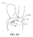
FIG. 4A is a diagram depicting a patient wearing a temperature monitoring system comprising a monitor patch and a temperature probe and configured to measure body temperature of the patient according to certain aspects of the present disclosure.
FIG. 4B is a diagram providing an enlarged view of the temperature monitoring system depicted in FIG. 4A according to certain aspects of the present disclosure.
FIG. 4C is a diagram providing an enlarge view of an alternative monitoring system according to certain aspects of the present disclosure.
FIG. 4D is a diagram depicting another alternative monitoring system according to certain aspects of the present disclosure.
FIGS. 5A-D are diagrams depicting some exemplary embodiments of the temperature probe depicted in FIG. 4B according to alternative aspects of the present disclosure.
FIGS. 6A-B are diagrams depicting two temperature-sensor interface configurations comprising exemplary temperature probes and sensor interfaces according to alternative aspects of the present disclosure.
FIG. 7 is a graph of a measured temperature reading versus time for illustrating an exemplary temperature monitoring scheme according to certain aspects of the present disclosure.
FIG. 8A is diagram depicting a realistic temperature reading (T) versus time (t) graph associated with a temperature monitoring system according to certain aspects of the present disclosure.
FIG. 8B shows a graph illustrating an exemplary temperature monitoring algorithm based on certain acceptance conditions according to certain aspects of the present disclosure.
FIG. 9 is a flowchart illustrating an exemplary process associated with the exemplary temperature monitoring algorithm of FIG. 8B according certain aspects of the present disclosure.
DETAILED DESCRIPTION
Periodic monitoring of patients in a hospital is desirable at least to ensure that patients do not suffer an un-noticed sudden deterioration in their condition or a secondary injury during their stay in the hospital. It is impractical to provide continuous monitoring by a clinician and cumbersome to connect sensors to a patient, which are then connected to a fixed monitoring instrument by wires. Furthermore, systems that sound an alarm when the measured value exceeds a threshold value may sound alarms so often and in situations that are not truly serious that such alarms are ignored by clinicians.
Measuring vital signs is difficult to do on a continuous basis. Accurate measurement of cardiac pulse, for example, can be done using an electrocardiograph (ECG or EKG) to detect the electrical activity of the heart. An EKG machine may use up to 12 electrodes placed at various points on the body to detect various signals associated with the cardiac function. Another common piece of equipment is termed a “heart rate monitor.” Widely sold for use in exercise and physical training, heart rate monitors may comprise a torso band in which are embedded two electrodes held against the skin and a small electronics package. Such heart rate monitors can communicate wirelessly to other equipment such as a small device that is worn like a wristwatch and that can transfer data wirelessly to a personal computer (PC).
Monitoring of patients that is referred to as “continuous” is frequently periodic, in that measurements are taken at intervals. In many cases, the process to make a single measurement takes a certain amount of time, such that even back-to-back measurements produce values at an interval equal to the time that it takes to make the measurement. For the purpose of vital sign measurement, a sequence of repeated measurements can be considered to be “continuous” when the vital sign is not likely to change an amount that is of clinical significance within the interval between measurements. For example, a measurement of blood pressure every 10 minutes may be considered “continuous” if it is considered unlikely that a patient's blood pressure can change by a clinically significant amount within 10 minutes. The interval appropriate for measurements to be considered continuous may depend on a variety of factors including the type of injury or treatment and the patient's medical history. Compared to intervals of 4-8 hours for manual vital sign measurement in a hospital, measurement intervals of 30 minutes to several hours may still be considered “continuous.”
Certain exemplary embodiments of the present disclosure include a system that comprises a vital-signs monitor patch that is attached to the patient, and a bridge that communicates with monitor patches and links them to a central server that processes the data, where the server can send data and alarms to a hospital system according to algorithms and protocols defined by the hospital.
The construction of the vital-signs monitor patch is described according to certain aspects of the present disclosure. As the patch may be worn continuously for a period of time that may be several days, as is described in the following disclosure, it is desirable to encapsulate the components of the patch such that the patient can bathe or shower and engage in their normal activities without degradation of the patch function. An exemplary configuration of the construction of the patch to provide a hermetically sealed enclosure about the electronics is disclosed.
In the following detailed description, numerous specific details are set forth to provide a full understanding of the present disclosure. It will be apparent, however, to one ordinarily skilled in the art that embodiments of the present disclosure may be practiced without some of the specific details. In other instances, well-known structures and techniques have not been shown in detail so as not to obscure the disclosure.
FIG. 1 discloses a vital sign monitoring system according to certain embodiments of the present disclosure. The vital sign monitoring system 12 includes vital-signs monitor patch 20, bridge 40, and surveillance server 60 that can send messages or interact with peripheral devices exemplified by mobile device 90 and workstation 100.
Monitor patch 20 resembles a large adhesive bandage and is applied to a patient 10 when in use. It is preferable to apply the monitor patch 20 to the upper chest of the patient 10 although other locations may be appropriate in some circumstances. Monitor patch 20 incorporates one or more electrodes (not shown) that are in contact with the skin of patient 10 to measure vital signs such as cardiac pulse rate and respiration rate. Monitor patch 20 also may include other sensors such as an accelerometer, temperature sensor, or oxygen saturation sensor to measure other characteristics associated with the patient. These other sensors may be internal to the monitor patch 20 or external sensors that are operably connected to the monitor patch 20 via a cable or wireless connection. Monitor patch 20 also includes a wireless transmitter that can both transmit and receive signals. This transmitter is preferably a short-range, low-power radio frequency (RF) device operating in one of the unlicensed radio bands. One band in the United States (US) is, for example, centered at 915 MHz and designated for industrial, scientific and medical (ISM) purposes. An example of an equivalent band in the European Union (EU) is centered at 868 MHz. Other frequencies of operation may be possible dependent upon the International Telecommunication Union (ITU), local regulations and interference from other wireless devices.
Surveillance server 60 may be a standard or virtualized computer server connected to the hospital communication network and preferably located in the hospital data center or computer room, although other locations may be employed. The server 60 stores and processes signals related to the operation of the patient monitoring system 12 disclosed herein including the association of individual monitor patches 20 with patients 10 and measurement signals received from multiple monitor patches 20. Hence, although only a single patient 10 and monitor patch 20 are depicted in FIG. 1, the server 60 is able to monitor the monitor patches 20 for multiple patients 10.
Bridge 40 is a device that connects, or “bridges”, between monitor patch 20 and server 60. Bridge 40 communicates with monitor patch 20 over communication link 30 operating, in these exemplary embodiments, at approximately 915 MHz and at a power level that enables communication link 30 to function up to a distance of approximately 10 meters. It is preferable to place a bridge 40 in each room and at regular intervals along hallways of the healthcare facility where it is desired to provide the ability to communicate with monitor patches 20. Bridge 40 also is able to communicate with server 60 over network link 50 using any of a variety of computer communication systems including hardwired and wireless Ethernet using protocols such as 802.11a/b/g or 802.3af. As the communication protocols of communication link 30 and network link 50 may be very different, bridge 40 provides data buffering and protocol conversion to enable bidirectional signal transmission between monitor patch 20 and server 60.
While the embodiments illustrated by FIG. 1 employ a bridge 20 to provide communication link between the monitor patch 20 and the server 60, in certain alternative embodiments, the monitor patch 20 may engage in direct wireless communication with the server 60. In such alternative embodiments, the server 60 itself or a wireless modem connected to the server 60 may include a wireless communication system to receive data from the monitor patch 20.
In use, a monitor patch 20 is applied to a patient 10 by a clinician when it is desirable to continuously monitor basic vital signs of patient 10 while patient 10 is, in this embodiment, in a hospital. Monitor patch 20 is intended to remain attached to patient 10 for an extended period of time, for example, up to 5 days in certain embodiments, limited by the battery life of monitor patch 20. In some embodiments, monitor patch 20 is disposable when removed from patient 10.
Server 60 executes analytical protocols on the measurement data that it receives from monitor patch 20 and provides this information to clinicians through external workstations 100, preferably personal computers (PCs), laptops, or smart phones, over the hospital network 70. Server 60 may also send messages to mobile devices 90, such as cell phones or pagers, over a mobile device link 80 if a measurement signal exceeds specified parameters. Mobile device link 80 may include the hospital network 70 and internal or external wireless communication systems that are capable of sending messages that can be received by mobile devices 90.
FIG. 2A is a perspective view of the vital-signs monitor patch 20 shown in FIG. 1 according to certain aspects of the present disclosure. In the illustrated embodiment, the monitor patch 20 includes component carrier 23 comprising a central segment 21 and side segments 22 on opposing sides of the central segment 21. In certain embodiments, the central segment 21 is substantially rigid and includes a circuit assembly (24, FIG. 2B) having electronic components and battery mounted to a rigid printed circuit board (PCB). The side segments 22 are flexible and include a flexible conductive circuit (26, FIG. 2B) that connect the circuit assembly 24 to electrodes 28 disposed at each end of the monitor patch 20, with side segment 22 on the right shown as being bent upwards for purposes of illustration to make one of the electrodes 28 visible in this view.
FIG. 2B is a cross-sectional view of the vital-signs patch 20 shown in FIGS. 1 and 2A according to certain aspects of the present disclosure. The circuit assembly 24 and flexible conductive circuit 26 described above can be seen herein. The flexible conductive circuit 26 operably connects the circuit assembly 24 to the electrodes 28. Top and bottom layers 23 and 27 form a housing 25 that encapsulate circuit assembly 28 to provide a water and particulate barrier as well as mechanical protection. There are sealing areas on layers 23 and 27 that encircles circuit assembly 28 and is visible in the cross-section view of FIG. 2B as areas 29. Layers 23 and 27 are sealed to each other in this area to form a substantially hermetic seal. Within the context of certain aspects of the present disclosure, the term ‘hermetic’ implies that the rate of transmission of moisture through the seal is substantially the same as through the material of the layers that are sealed to each other, and further implies that the size of particulates that can pass through the seal are below the size that can have a significant effect on circuit assembly 24. Flexible conductive circuit 26 passes through portions of sealing areas 29 and the seal between layers 23 and 27 is maintained by sealing of layers 23 and 27 to flexible circuit assembly 28. The layers 23 and 27 are thin and flexible, as is the flexible conductive circuit 26, allowing the side segment 22 of the monitor patch 20 between the electrodes 28 and the circuit assembly 24 to bend as shown in FIG. 2A.
FIG. 2C is a functional block diagram 200 illustrating exemplary electronic and sensor components of the monitor patch 20 of FIG. 1 according to certain aspects of the present disclosure. The block diagram 200 shows a processing and sensor interface module 201 and external sensors 232, 234 connected to the module 201. In the illustrated example, the module 201 includes a processor 202, a wireless transceiver 207 having a receiver 206 and a transmitter 209, a memory 210, a first sensor interface 212, a second sensor interface 214, a third sensor interface 216, and an internal sensor 236 connected to the third sensor interface 216. The first and second sensor interfaces 212 and 214 are connected to the first and second external sensors 232, 234 via first and second connection ports 222, 224, respectively. In certain embodiments, some or all of the aforementioned components of the module 201 and other components are mounted on a PCB.
Each of the sensor interfaces 212, 214, 216 can include one or more electronic components that are configured to generate an excitation signal or provide DC power for the sensor that the interface is connected to and/or to condition and digitize a sensor signal from the sensor. For example, the sensor interface can include a signal generator for generating an excitation signal or a voltage regulator for providing power to the sensor. The sensor interface can further include an amplifier for amplifying a sensor signal from the sensor and an analog-to-digital converter for digitizing the amplified sensor signal. The sensor interface can further include a filter (e.g., a low-pass or bandpass filter) for filtering out spurious noises (e.g., a 60 Hz noise pickup).
The processor 202 is configured to send and receive data (e.g., digitized signal or control data) to and from the sensor interfaces 212, 214, 216 via a bus 204, which can be one or more wire traces on the PCB. Although a bus communication topology is used in this embodiment, some or all communication between discrete components can also be implemented as direct links without departing from the scope of the present disclosure. For example, the processor 202 may send data representative of an excitation signal to the sensor excitation signal generator inside the sensor interface and receive data representative of the sensor signal from the sensor interface, over either a bus or direct data links between processor 202 and each of sensor interface 212, 214, and 216.
The processor 202 is also capable of communication with the receiver 206 and the transmitter 209 of the wireless transceiver 207 via the bus 204. For example, the processor 202 using the transmitter and receiver 209, 206 can transmit and receive data to and from the bridge 40. In certain embodiments, the transmitter 209 includes one or more of a RF signal generator (e.g., an oscillator), a modulator (a mixer), and a transmitting antenna; and the receiver 206 includes a demodulator (a mixer) and a receiving antenna which may or may not be the same as the transmitting antenna. In some embodiments, the transmitter 209 may include a digital-to-analog converter configured to receive data from the processor 202 and to generate a base signal; and/or the receiver 206 may include an analog-to-digital converter configured to digitize a demodulated base signal and output a stream of digitized data to the processor 202.
The processor 202 may include a general-purpose processor or a specific-purpose processor for executing instructions and may further include a memory 219, such as a volatile or non-volatile memory, for storing data and/or instructions for software programs. The instructions, which may be stored in a memory 219 and/or 210, may be executed by the processor 202 to control and manage the wireless transceiver 207, the sensor interfaces 212, 214, 216, as well as provide other communication and processing functions.
The processor 202 may be a general-purpose microprocessor, a microcontroller, a Digital Signal Processor (DSP), an Application Specific Integrated Circuit (ASIC), a Field Programmable Gate Array (FPGA), a Programmable Logic Device (PLD), a controller, a state machine, gated logic, discrete hardware components, or any other suitable device or a combination of devices that can perform calculations or other manipulations of information.
Information, such as program instructions, data representative of sensor readings, preset alarm conditions, threshold limits, may be stored in a computer or processor readable medium such as a memory internal to the processor 202 (e.g., the memory 219) or a memory external to the processor 202 (e.g., the memory 210), such as a Random Access Memory (RAM), a flash memory, a Read Only Memory (ROM), a Programmable Read-Only Memory (PROM), an Erasable PROM (EPROM), registers, a hard disk, a removable disk, or any other suitable storage device.
In certain embodiments, the internal sensor 236 can be one or more sensors configured to measure certain properties of the processing and sensor interface module 201, such as a board temperature sensor thermally coupled to a PCB. In other embodiments, the internal sensor 236 can be one or more sensors configured to measure certain properties of the patient 10, such as a motion sensor (e.g., an accelerometer) for measuring the patient's motion or position with respect to gravity.
The external sensors 232, 234 can include sensors and sensing arrangements that are configured to produce a signal representative of one or more vital signs of the patient to which the monitor patch 20 is attached. For example, the first external sensor 232 can be a set of sensing electrodes that are affixed to an exterior surface of the monitor patch 20 and configured to be in contact with the patient for measuring the patient's respiratory rate, and the second external sensor 234 can include a temperature sensing element (e.g., a thermocouple or a thermistor or resistive thermal device (RTD)) affixed, either directly or via an interposing layer, to skin of the patient 10 for measuring the patient's body temperature. In other embodiments, one or more of the external sensors 232, 234 or one or more additional external sensors can measure other vital signs of the patient, such as blood pressure, pulse rate, or oxygen saturation.
FIG. 3A is a functional block diagram illustrating exemplary electronic components of bridge 40 of FIG. 1 according to one aspect of the subject disclosure. Bridge 40 includes a processor 310, radio 320 having a receiver 322 and a transmitter 324, radio 330 having a receiver 332 and a transmitter 334, memory 340, display 345, and network interface 350 having a wireless interface 352 and a wired interface 354. In some embodiments, some or all of the aforementioned components of module 300 may be integrated into single devices or mounted on PCBs.
Processor 310 is configured to send data to and receive data from receiver 322 and transmitter 324 of radio 320, receiver 332 and transmitter 334 of radio 330 and wireless interface 352 and wired interface 354 of network interface 350 via bus 314. In certain embodiments, transmitters 324 and 334 may include a radio frequency signal generator (oscillator), a modulator, and a transmitting antenna, and the receivers 322 and 332 may include a demodulator and antenna which may or may not be the same as the transmitting antenna of the radio. In some embodiments, transmitters 324 and 334 may include a digital-to-analog converter configured to convert data received from processor 310 and to generate a base signal, while receivers 322 and 332 may include analog-to-digital converters configured to convert a demodulated base signal and sent a digitized data stream to processor 310.
Processor 310 may include a general-purpose processor or a specific-purpose processor for executing instructions and may further include a memory 312, such as a volatile or non-volatile memory, for storing data and/or instructions for software programs. The instructions, which may be stored in memories 312 or 340, may be executed by the processor 310 to control and manage the transceivers 320, 330, and 350 as well as provide other communication and processing functions.
Processor 310 may be a general-purpose microprocessor, a microcontroller, a Digital Signal Processor (DSP), an Application Specific Integrated Circuit (ASIC), a Field Programmable Gate Array (FPGA), a Programmable Logic Device (PLD), a controller, a state machine, gated logic, discrete hardware components, or any other suitable device or a combination of devices that can perform calculations or other manipulations of information.
Information such as data representative of sensor readings may be stored in memory 312 internal to processor 310 or in memory 340 external to processor 310 which may be a Random Access Memory (RAM), flash memory, Read Only Memory (ROM), Programmable Read Only Memory (PROM), Erasable Programmable Read Only Memory (EPROM), registers, a hard disk, a removable disk, a Solid State Memory (SSD), or any other suitable storage device.
Memory 312 or 340 can also store a list or a database of established communication links and their corresponding characteristics (e.g., signal levels) between the bridge 40 and its related monitor patches 20. In the illustrated example of FIG. 3A, the memory 340 external to the processor 310 includes such a database 342; alternatively, the memory 312 internal to the processor 310 may include such a database.
FIG. 3B is a functional block diagram illustrating exemplary electronic components of server 60 of FIG. 1 according to one aspect of the subject disclosure. Server 60 includes a processor 360, memory 370, display 380, and network interface 390 having a wireless interface 392 and a wired interface 394. Processor 360 may include a general-purpose processor or a specific-purpose processor for executing instructions and may further include a memory 362, such as a volatile or non-volatile memory, for storing data and/or instructions for software programs. The instructions, which may be stored in memories 362 or 370, may be executed by the processor 360 to control and manage the wireless and wired network interfaces 392, 394 as well as provide other communication and processing functions.
Processor 360 may be a general-purpose microprocessor, a microcontroller, a Digital Signal Processor (DSP), an Application Specific Integrated Circuit (ASIC), a Field Programmable Gate Array (FPGA), a Programmable Logic Device (PLD), a controller, a state machine, gated logic, discrete hardware components, or any other suitable device or a combination of devices that can perform calculations or other manipulations of information.
Information such as data representative of sensor readings may be stored in memory 362 internal to processor 360 or in memory 370 external to processor 360 which may be a Random Access Memory (RAM), flash memory, Read Only Memory (ROM), Programmable Read Only Memory (PROM), Erasable Programmable Read Only Memory (EPROM), registers, a hard disk, a removable disk, a Solid State Memory (SSD), or any other suitable storage device.
Memory 362 or 370 can also store a database of communication links and their corresponding characteristics (e.g., signal levels) between monitor patches 20 and bridges 40. In the illustrated example of FIG. 3B, the memory 370 external to the processor 360 includes such a database 372; alternatively, the memory 362 internal to the processor 360 may include such a database.
As indicated above with respect to FIG. 2C, certain embodiments of the monitor patch 20 are configured to operate with external sensors that are in turn configured to produce a signal representative of one or more vital signs of the patient to whom the monitor patch 20 is attached. For example, the second external sensor 234 can be a temperature probe that includes a temperature sensing element (e.g., a thermocouple or thermistor) affixed, either directly or via an interposing layer, to skin of the patient 10 for measuring the patient's body temperature. FIG. 4A is a diagram depicting a patient 10 wearing a temperature monitoring system 20A comprising a monitor patch 20 and a temperature probe 400 that is configured to measure body temperature of the patient 10. In the illustrated example, the temperature probe 400 is configured for axillary temperature sensing of the patient 10 to whom the monitor patch 20 is attached. The monitor patch 20 is attached to the chest 11 of the patient 10, with a sensing portion of the temperature probe 400 retained in the axilla 12 of the patient 10 during body temperature monitoring.
FIG. 4B is a diagram providing an enlarged view of the monitoring system 20A depicted in FIG. 4A according to certain aspects of the present disclosure. As indicated above, the monitor patch 20 is attached to the chest 11 of the patient 10 via, e.g., an adhesive backing (not shown). The temperature probe 400 has a proximal end 401 and a distal end 403 and includes a wiring portion 410, a body connection portion 430B, and a sensing portion 420 disposed between the wiring and body connection portions 410, 430B. The proximal end 401 of the temperature probe 400 is connected to the monitor patch 20 at its connection port 22. In certain embodiments, the proximal end 401 of the temperature probe 400 is removably attached (e.g., plugged) to the monitor patch 20. In other embodiments, the proximal end 401 is fixedly attached (e.g., epoxied or fused) to the monitor patch 20.
The sensing portion 420 of the temperature probe 400 is configured for placement within the axilla 12 of the patient 10 and includes a temperature sensing element (e.g., 234A-D of FIGS. 5A-D and 234E-F of FIGS. 6A-B). The wiring portion 410 of the temperature probe 400 includes one or more electrical conductors (512, 514 of FIGS. 5A-D and FIGS. 6A-B) for carrying a signal responsive to a change in body temperature of the patient 10 between the temperature sensing element 234 and the monitor patch 20. In the illustrated example of FIG. 4B, the wiring portion 410 includes a flexible cable comprising a tubing and electrical conductors (e.g., a pair of twisted copper wires) placed within the tubing. The wiring portion 410 includes a first coiled section 414 and a second coiled section 418. The coiled sections 414, 418 serve a number of functions including, but not limited to, holding the sensing portion 420 as high as possible in the axilla 12, accommodating arm movements by reducing the “sawing” effect of a straight wire moving along its axis when the patient's arm is moving, creating a wider surface of contact with the skin, thus increasing patient's comfort, creating a contact surface with the skin that does not tend to cause irritation as much as a straight wire would.
In the illustrated example, the monitoring system 20A further includes an adhesive element 416 (e.g., a tape) coupled to the cable between the first and second coiled sections 414, 418 and configured to attach the wiring portion 410 of the cable to the patient's body, e.g., at a point between the chest 11 and the armpit 12 of the patient.
The body connection portion 430B has one end connected to the sensing portion 420 and is configured to be attached to another body portion of the patient 10 such that the sensing portion 420 of the temperature probe 400 can be retained within the axilla 12 of the patient 10. In the illustrated example, such attachment is achieved via an adhesive element 426 (e.g., a tape) coupled to the distal end of the body connection portion 430B. The coupled adhesive element 426 is then attached to a second body portion 13 (e.g., the back of the patient's arm) of the patient 10. In the illustrated embodiment of FIG. 4B, the body connection portion 430B includes an elastic tubing comprising an elastic polymers (elastomers) such as natural rubber, synthetic polyisoprene, butyl rubber, and the like. In such embodiments, the adhesive element 426 is attached to the patient's body while the elastic tubing is in its stretched state such that the restorative (“pulling”) tensile force in the stretched tubing helps to hold the temperature sensing portion 420 in place within the axilla 12 of the patient. The adhesive elements 416, 426 can be pre-attached adhesive tabs with a peel-off backing. Alternatively, the adhesive elements 416, 426 can be pre-attached fixture tab that allow for the use of a standard medical tape. Openings (holes, slots, etc.) can be present in both cases to allow skin to breathe. The adhesive elements 416, 426 are preferably positioned at about the same vertical level, high enough so both of the stretchable coiled sections 414, 418 would pull the sensing portion 420 upward.
FIG. 4C is a diagram providing an enlarged view of an alternative monitoring system 20B according to certain aspects of the present disclosure. The monitoring system 20B is substantially the same as the monitoring system 20A, except an additional (e.g., third) coiled section 419 is provided in body connection portion 430C in place of the elastic tubing 430B. The additional coiled section 419 can provide all or some of the pulling force such as the one provided by the elastic tubing in the embodiment of FIG. 4B. In one or more implementations, the coiled section 419 acts as a spring. The remainder of the body connection portion 430C may include an elastic or inelastic flexible tubing.
FIG. 4D is a diagram depicting another alternative monitoring system 20C according to certain aspects of the present disclosure. The monitoring system 20C includes a first stretchable component 420, a second stretchable component 430, and a third stretchable component 440. The monitoring system 20C further comprises adhesive elements 416C, 426C. At least some of the stretchable components (e.g., 440) include a tubing 442 with a flexible boot 424 at the end thereof as illustrated by an enlarged view of an end section 407 of the stretchable component 440. The enlarged view shows the stretchable component 440 in its unstretched state (top) and in its stretched state (bottom). The adhesive elements 416C, 426C are substantially similar to the adhesive elements 416, 426 described above with respect to the monitoring system 20A. The adhesive element 426C depicted in the enlarged view include slotted holes that allow skin to breathe.
A multitude of modifications and additions to the illustrated embodiments of FIGS. 4B, 4C and 4D are possible without departing from the scope of the disclosure. For example, the body connection portion 430 of the temperature probe 400 can include one or more coiled sections similar to the coiled section 414 of the wiring portion 410. Any or all of the coiled sections 414, 418, 419 in the embodiments of FIGS. 4B and 4C may be replaced with elastic elements (e.g., elastic tubing). The adhesive element 416 may be coupled to the body connection portion 430 at a point different than the distal end of the body connection portion 430. In certain embodiments, entirely different means of attaching the body connection portion 430 to the patient's body may be used. For example, the body connection portion 430 may itself be in the form of an adhesive tape that can stick to the body of the patient 10 or may include an elastic loop (e.g., a rubber band) to be placed around the patient's arm.
While the temperature probe 400 in the illustrated embodiments of FIGS. 4A-C is shown to be operatively coupled to a vital-sign monitor patch worn by the patient 10, the temperature probe 400 may be alternatively operatively coupled to other types of monitoring devices such as a stationary monitoring unit located near the patient's hospital bed. Such a stationary monitoring unit can take readings of the patient's body temperature based on a signal from the temperature probe 400 and send the temperature readings to a surveillance server via a wired or wireless connection and make other decisions such as providing an indication of an alarm condition (e.g., a high body temperature condition or a loss of thermal contact between the temperature probe and the patient).
FIGS. 5A-D are diagrams depicting various exemplary embodiments of the temperature probe according to alternative aspects of the present disclosure. For the purposes of illustration only, without an intent to limit the scope of the present disclosure in any way, the embodiments will be described with references to elements of FIG. 4B. For clarity, each of the diagrams focuses on a region 500A-D (corresponding to region 500 in FIG. 4B) of the thermocouple 400 where sensing portion 420A-D interfaces with wiring portion 410A-D and body connection portions 430A-D. The figures are not drawn to scale.
In the first exemplary embodiment of the temperature probe 400 depicted in FIG. 5A, the wiring portion 410A, the sensing portion 420A, and the body connection portion 430A comprise a single hollow flexible cable 401A. The wiring portion 410A of the flexible cable 401A includes a first electrical conductor 512 and a second electrical conductor 514. The sensing portion of the flexible cable 401A houses a temperature sensing element 234A that is electrically connected to the first and second electrical conductors 512, 514. The temperature sensing element 234A is configured to make thermal contact with the axilla of the patient 10 through the surrounding flexible cable 401A. In the illustrated example, the body connection portion 430A of the flexible cable 401A is empty inside.
In the second exemplary embodiment of the temperature probe 400 depicted in FIG. 5B, the wiring portion 410B comprises a first hollow flexible cable 411B having a first electrical conductor 512 and a second electrical conductor 514. The sensing portion 420B includes a temperature sensing element 234B. In the illustrated example, the temperature sensing element 234B is mechanically connected (e.g., glued or fused) to an end portion of the first flexible cable 411B and is electrically connected to the first and second electrical conductors 512, 514. The temperature sensing element 234B is configured to make a direct physical and thermal contact with the axilla 12 of the patient 10 (i.e., not through a flexible cable). The body connection portion 430B comprises a second hollow flexible cable 431B. In the illustrated example, the second flexible cable 431B is empty inside.
In the third exemplary embodiment of the temperature probe 400 depicted in FIG. 5C, wiring portion 410C comprises a first flexible cable 411C having a first electrical conductor 512 and a second electrical conductor 514. The sensing portion 420C and body connection portion 430C comprise a second hollow flexible cable 501C. The second flexible cable 501C is mechanically connected (e.g., glued or fused) to an end portion of the first flexible cable 411C. The sensing portion 420C of the second flexible cable 501C houses a temperature sensing element 234C that is electrically connected to the first and second electrical conductors 512, 514. The temperature sensing element 234C is configured to make a thermal contact with the axilla of a patient through the surrounding second flexible cable 501C. The body connection portion 430C of the second flexible cable 401C is empty inside.
In the fourth exemplary embodiment of the temperature probe 400 depicted in FIG. 5D, the wiring portion 410D and the sensing portion 420D comprise a first flexible cable 401D. The wiring portion 410D of the first flexible cable 401D includes a first electrical conductor 512 and a second electrical conductor 514. The sensing portion 420D of the first flexible cable 401D houses a temperature sensing element 234D. The temperature sensing element 234D is electrically connected to the first and second electrical conductors 512, 514. The body connection portion 430D comprises a flexible tape 432D that is mechanically connected (e.g., glued or fused) to the sensing portion 420D at the temperature sensing element 234D and/or an end portion of the first flexible cable 401D. In certain embodiments, the flexible tape 432D includes an adhesive section that can be attached to a body portion (e.g., the back of the patient's arm) so as to retain the sensing portion 420D of the temperature probe 400 within the axilla 12 of the patient 10.
The above embodiments of FIGS. 5A-5D are exemplary only, as other embodiments can be employed without departing from the scope of the present disclosure. For example, a modular arrangement in which the cables are snap connectable with the temperature sensing element can be employed, as well as other physical configurations.
FIGS. 6A-B are diagrams depicting two temperature-sensor interface configurations comprising exemplary temperature probes 400E, 400F and sensor interfaces 214E, 214F according to alternative aspects of the present disclosure. Each of the temperature probes 400E, 400F comprises respective wiring portion 410E, 410F and sensing portion 420E, 420F having temperature sensing element 234E, 234F. Each of the sensor interface circuits 214E, 214F is connected to the temperature probe 400E, 400F and configured to receives a sensor signal from the temperature sensing element 234E, 234F via electrical conductors 512, 514 in the wiring portion 410E, 410F of the probe 400E, 400F. As described above with respect to FIG. 2, the sensor interface 214E, 214F is part of a processing and sensor interface module (e.g., 201) of a vital-sign monitor patch (e.g., 20). For simplicity, each of the diagrams shows only a wiring portions 410E, 410F and a sensing portion 420E, 420F of the temperature probe 400E, 400F. The figures are not drawn to scale.
In the first exemplary probe-sensor interface configuration depicted in FIG. 6A, the temperature sensing element 234E is a thermocouple that comprises a junction 601 between two different metals. The junction 601 produces a voltage difference related to temperature at the junction 601. The junction is of dissimilar metals including specific alloys such as platinum and platinum-rhodium alloy (Type S) or chromel and alumel (Type K). This embodiment of a thermocouple is exemplary only, as other embodiments may be employed. For example, additional circuits/elements relating to cold junction compensation may be used. In some embodiments, the temperature sensing element may comprise a resistance temperature detector (RTD) based on platinum.
A signal representative of the voltage difference produced at the junction 601 of the thermocouple 234E is received by the sensor interface 214E via the first and second electrical conductors 512, 514 in the wiring portion 410E. The sensor interface 214E includes an amplifier 620E, an analog-to-digital converter (ADC) 630E and a current source 605. The current source 605 supplies a constant DC current that flows through the junction and produces a signal representative of the voltage difference across the junction. The signal is received at the minus input of the amplifier 620E. The received signal is amplified by the amplifier 620E, and the amplified signal is received by the ADC 630E at input port 632E. The ADC 630E digitizes the amplified signal and provides a stream of digitized data at output port 634E. The stream of digitized data is passed to a processor (e.g., 202 of FIG. 2) for further processing and/or transmission to a surveillance server (e.g., 60 of FIG. 1) via a bride (e.g., 40 of FIG. 1). In certain embodiments, the ADC 630E at its control data input port 636E receives from the processor a set of control data that configures one or more functionalities of the ADC 630E including, not limited to, its sampling (digitization) rate and dynamic range.
In the second exemplary probe-sensor interface depicted in FIG. 6B, the temperature sensing element 234F includes a thermistor 603, a type of resistor whose resistance varies with temperature. The thermistor 603 can be made from a material that has a positive temperature coefficient (PTC) (called a “PTC thermistor”) or from a material that has a negative temperature coefficient (NTC) (called a “NTC thermistor”).
Two electrical contacts 425 of the thermistor 603 are connected to the sensor interface circuit 214F via the first and second electrical conductors 512, 514 in the wiring portion 410F. The sensor interface circuit 214F includes a Wheatstone bridge 610F having three fixed resistors (R1, R2, and R3), an amplifier 620F, and an analog-to-digital converter (ADC) 630F. By the connection provided by the first and second electrical conductors 512, 514, the thermistor 603 functions as a fourth and variable resistor in the Wheatstone bridge 610F such that the bridge 610F outputs a signal that is responsive to a change in the resistance of the thermistor 603, which resistance is in turn responsive to a change in the body temperature of the patient 10. The signal generated at the Wheatstone bridge 610 is received by an amplifier 620F. An amplified signal at the output of the amplifier 620F is received by an input port 632F of the ADC 630F. The ADC 630F digitizes the received signal and provides a stream of digitized data at output port 634F. The stream of digitized data is passed to a processor (e.g., 202 of FIG. 2) for further processing and/or transmission to a surveillance server (e.g., 60 of FIG. 1). In certain embodiments, the ADC 630F at its control data input port 636F receives a set of control data that configures one or more functionalities of the ADC 630F including, not limited to its sampling (digitization) rate and dynamic range.
With references to FIGS. 1, 2 and 4A-B, the monitor patch 20 worn by the patient 10 receives a signal from a temperature sensing element (e.g., a thermocouple and a thermistor) of the temperature probe 400, the signal responsive to a change in body temperature of the patient 10. The signal is amplified and digitized into a stream of data by the sensor interface circuit 214 as explained above with respect to FIGS. 6A-B. The digitized signal is then received by the processor 202. The processor 202 generates a sequence of temperature readings based on the digitized signal. The processor 202 is operatively connected to a wireless communication system (e.g., the wireless transceiver 207) which transmits data indicative of the patient's body temperature to the surveillance server 60 via the bridge 40. In certain embodiments, the processor 202 performs a number of temperature monitoring functions on the temperature readings to determine, inter alia, a high temperature condition and occurrence and loss of thermal contact between the patient 10 and the temperature probe 400.
FIG. 7 is a graph 700 of a measured temperature reading (T) versus time (t) for illustrating an exemplary temperature monitoring scheme according to certain aspects of the present disclosure. The graph 700 shows a low temperature limit (TL) and a high temperature limit (TH) that are used in the temperature monitoring scheme. For the purposes of illustration only without an intent to limit the scope of the present disclosure in any way, the exemplary temperature monitoring scheme will be described with reference to elements of FIGS. 4A,B. At t=0, a body-probe contact between the body of the patient 10 and the temperature probe 400 is made, e.g., by securing the sensing portion 420 of the temperature probe 400 within the axilla 12 of the patient 10. A processor (the processor 202 of FIG. 2) executing a control program in the monitoring device (e.g., the monitor patch 20) can recognize the body-probe contact by a number of different ways. For example, the recognition can be achieved from the temperature reading rising sharply past the low temperature limit (TL) at a rate exceeding a first threshold rate of rise after having been below TL at least once.
As seen in FIG. 7, the temperature reading rises from an initial (e.g., open-air) value (T0) at t=t1 to an equilibrium value (T1) at t=t1 when the temperature sensing element has reached a thermal equilibrium with the patient's body.
At t=t2, the temperature reading begins to rise, indicating that the patient's body temperature is on the rise. At t=t3, the temperature reading exceeds the high temperature limit (TH). When this occurs, the processor executing control software in the monitoring device can invoke a high temperature handler routine in the control software and take a number of predetermined actions. For example, the processor can cause the transmitter 209 (FIG. 2) to start sending a signal indicative of the high temperature alarm condition to the surveillance server 60 either directly or via the bridge 40. In response, the surveillance server 60 can send a notification to a hospital system (e.g., the workstation 100 of FIG. 1). The monitor patch 20 can also set off an alarm, e.g., at the monitor patch 20 or at a stand alone monitoring unit or at a hospital system (e.g., the workstation 100 of FIG. 1), thereby notifying a nurse or other caregiver. The monitor patch 20 can enter into an alert operation mode from the normal operation mode and take and transmit the temperature readings (e.g., to the surveillance server 60) at a faster rate. For instance, the monitor patch 20 can take and transmit the temperature reading every 10 minutes during the normal operation mode, but does so every 2 minutes in the alert operation mode. In certain embodiments, the temperature monitoring scheme utilizes two high temperature limits (TH1 and TH2, where TH2>TH1) and different sets of predetermined actions are performed depending on whether the temperature reading has exceeded only TH1 or both TH1 and TH2.
In the illustrated example of FIG. 7, it is assumed that at t=t4, a nurse who has been notified of the high temperature condition of the patient 10 has decided to administer a fever-reducing medication to the patient 10. Responding to the fever-reducing medication, the patient's body temperature reading begins to fall gradually and reach a relatively stable level below TH.
However, at t=t5, the body-probe contact is lost due to, e.g., the patient 10 opening the arm in a manner that causes the sensing portion 420 of the temperature probe 400 to be detached from the axilla 12 of the patient 10, or the temperature probe 400 accidentally falls off the patient's body. The loss of body-probe contact causes the temperature reading to fall towards a lower (e.g., open-air) value at a relatively sharp rate of decline. In certain embodiments of the temperature monitoring system 20A, the processor executing control software in the monitor patch 20 can detect the loss of body-probe contact by computing a rate of decline in the sequence of temperature readings and comparing the computed rate of decline to a threshold rate of decline. If the rate of decline exceeds the threshold rate of decline for a predetermined number of samples (e.g., 1-4), the processor determines that the body-probe contact has been lost and generates an indication of the loss of contact. In the illustrated example of FIG. 7, the loss of body-probe contact is detected at t=t6. As can be seen from FIG. 7, the detection scheme based on the rate of decline described herein can detect the loss of contact earlier than a scheme relying on the temperature readings falling below the low temperature limit (TL). The latter scheme would not detect the loss of contact until t=t7.
In certain embodiments, an indication of the loss of contact is wirelessly transmitted to the bridge 40 to be sent to the surveillance server 60, and the surveillance server 60 then provides a notification of the loss of contact to a hospital system (e.g., the workstation 100 of FIG. 1). In other embodiments, in addition or in lieu of the wireless transmission of the indication, the monitor patch 20 itself may sound an alarm indicating the loss of contact to the patient 10 or a nurse or caregiver who is near the patient 10.
In certain embodiments, the monitor patch 20, after providing the indication, enters a sleep mode in which no additional temperature readings are taken. Alternatively, the monitor patch 20 can continue to take additional temperature readings to determine whether a new body-probe contact has been established.
FIG. 8A is diagram depicting a realistic temperature reading (T) versus time (t) graph 800A associated with a temperature monitoring system (e.g., 20) according to certain aspects of the present disclosure. The temperature readings have peaks (e.g., 811, 812) and valleys (e.g., 854, 855). The up-and-down fluctuations in the temperature readings can be caused by movements of a patient's arm (up and down/back and forth), for example. This is because arm movements can affect the quality of thermal contact between the sensing portion 420 of the temperature probe 400 and the axilla 12 of the patient 10. In general, when the temperature readings are rising rapidly as between reading 854 and reading 812, the rise may be attributable to a transition from a relatively poor thermal contact to a good thermal contact, e.g., by armpit closing. On the other hand, when the temperature readings are decreasing rapidly as between reading 853 and reading 854, the decrease may be attributable to a transition from a relatively good thermal contact to a poor thermal contact caused, e.g., by armpit opening up or the temperature probe being detached from the patient 10, thereby partially or fully exposing the sensing portion 420 to ambient air. A reading taken while the quality of thermal contact is poor is likely to be inaccurate, and thus it is desirable to identify occurrence of such a poor thermal contact so that inaccurate readings associated with the poor thermal contact may be rejected, and only valid temperature readings associated with a good thermal contact are reported, e.g., to the surveillance server 60. In addition, a prolonged loss of thermal contact may be detected and reported so that the patient 10 and/or a caregiver can be alerted. As used herein, the term “poor thermal contact” refers to partial or complete loss of contact between a temperature probe and a person to whom the temperature probe is supposed to be attached.
In certain aspects of the present disclosure, the monitoring system 20 achieves these objectives by adopting the following principles:
    • 1) Only maximum readings (peaks or plateaus) are considered as potentially valid readings.
    • 2) Temperature readings on a downward slope are considered to be associated with a poor thermal contact.
    • 3) Given an almost impossible rate of decay of the core body temperature (e.g., −2 C/h), any peak or plateau below this threshold decay rate are rejected.
Applying these principles, a current (new) temperature reading (TNEW) is reported as a new valid temperature reading and replaces the current maximum temperature reading (TMAX) if TNEW fulfills at least one of the following acceptance conditions:
    • Condition 1: Initial stabilization is just completed;
    • Condition 2: (TNEW>TMAX); or
    • Condition 3: (TNEW<TMAX) AND a peak/plateau (e.g., a local maximum) is detected AND a gradient condition, namely, the peak/plateau is at or above a threshold decay curve representing the threshold decay rate (e.g., e.g., −2 C/h), is satisfied.
      Conversely, if the current temperature reading fails to satisfy all of these conditions, the reading is considered inaccurate and rejected, and the monitoring system 20 retains the current TMAX as the currently effective temperature reading value.
FIG. 8B shows a graph 800B graphically illustrating an exemplary temperature monitoring algorithm based on the above-enumerated acceptance conditions according to certain aspects of the present disclosure. FIG. 9 is a flowchart illustrating an exemplary process 900 associated with the exemplary temperature monitoring algorithm of FIG. 8B according certain aspects of the present disclosure. Indicated on the graph 800B are peak temperature readings (e.g., in between 811-819) that satisfy at least one of Conditions 1-3 enumerated above. Lines (straight or curvilinear) 831-839 represent currently effective temperature reading values, e.g., the values that the monitoring system 20 considers as the current axillary temperature of the patient 10. Saw-tooth-shaped curves 841-849 represent threshold decay curves generated based on a threshold decay rate (e.g., e.g., −2 C/h) discussed above with respect to Condition 3.
The algorithm 900 begins at start state 901 and proceeds to operation 910 in which a new temperature reading (TNEW) is generated. By way of example, the TNEW reading can be generated by a processor of the monitor patch 20 based on a signal generated by a temperature sensing element (e.g., 234A-D of FIG. 5A-D) of the temperature probe 400. As described above, the sensing element can be a thermocouple (234E of FIG. 6A), thermistor (234F of FIG. 6B) or any another temperature transducer configured to generate a signal responsive to a change in body temperature of a person to whom the temperature probe 400 is attached.
The algorithm 900 proceeds to decision state 920 in which a query is made as to whether an initial stabilization (e.g., a thermal equilibrium) has been completed for the temperature readings, e.g., after an initial attachment of the temperature probe 400 to the patient 10 or after a prolonged loss of thermal contact. This query is designed to determine whether the current TNEW reading satisfies Condition 1, e.g., whether the monitoring has gone through or completed its stabilization phase.
In certain embodiments, the decision state 920 can involve, for example, determining whether the current and recent temperature readings have flattened out after a sharp increase by monitoring a slope (e.g., derivative) or an average of slopes of the temperature readings versus time. In other embodiments, the decision state 920 can involve waiting for a certain period of time (e.g. 15 minutes) before reporting a value, even though some peaks or plateaus might be found. After that stabilization period, the maximum value found will be reported as the first value. The purpose of the stabilization period is to reduce chances of having low peaks of temperature being reported right after system activation because of the fact that the gradient criterion cannot be applied (gradient criterion requires an initial value). For example, if a peak is found after activation, without the gradient criterion to discard it, it would be reported as a valid reading. Waiting 15 minutes and taking the maximum value offers better chances of starting with a more accurate value. The above examples illustrate simple stabilization algorithms (e.g., waiting Z minutes and taking the maximum peak/plateau value). There can be different methods of obtaining a first reading such as using a predictive algorithm.
If answer to the query a the decision state 920 is NO, (initial stabilization not completed), the process 900 loops back to the operation 910 in which another TNEW reading is generated. On the other hand, if answer to the query at the decision state 920 is YES (initial stabilization completed), the process 900 proceeds to operation 930 in which the new temperature reading (TNEW) is reported, and to operation 940 in which the TNEW reading is assigned to TMAX. In the illustrated example of FIG. 8B, a first temperature reading 851 is taken at time 801, e.g., after an initial attachment of the temperature probe 400 to the patient 10, and an initial stabilization is determined to be completed at reading 811.
The process 900 then proceeds to operation 950 in which another TNEW reading is generated and then to decision state 960 in which a query is made as to whether the TNEW reading obtained at the operation 950 is larger than the current maximum temperature reading (TMAX), which at this point is equal to the value of the initially-stabilized temperature reading 811. This query is designed to determine whether the current TNEW reading satisfies Condition 2, namely TNEW>TMAX. If answer to the query is YES (TNEW>TMAX) the process 900 loops back to the operations 930 and 940 in which the current TNEW reading is reported and assigned to TMAX.
On the other hand, if the answer to the query at the decision state 960 is NO (TNEW≦TMAX), the process 900 proceeds to decision states 970 in which a first query is made as to whether the new temperature reading corresponds to a peak (e.g., local maximum) or a plateau (e.g., relatively flat region after a local maximum), and, if so, a second query is made as to whether the peak/plateau satisfies the gradient condition, namely, whether the peak/plateau is at or above a corresponding one of the threshold decay curves 841-849 representing the threshold decay rate (e.g., −2 C/h). The first and second queries of the decision state 970 are designed to determine whether the current TNEW reading satisfies Condition 3. In certain embodiments, the first query relating to the occurrence of a peak/plateau involves obtaining a sequence of temperature readings and retroactively identifying one of the readings corresponding to a local maximum. If the first and second queries of the decision state 970 are both satisfied (YES), the process 900 loops back to the operations 930 and 940 in which the current TNEW reading is reported and assigned to TMAX.
On the other hand, if at least one of the first and second queries is not satisfied (NO), the process 900 proceeds to another decision state 980 in which a query is made as to whether a maximum duration for the current TMAX reading has been exceeded. This query detects a prolonged loss of thermal contact between the temperature probe 420 and the axilla 12 of the patient 10. In certain exemplary embodiments, the maximum duration is preset at a value between about 10 and 30 minutes. If the query at the decision state 980 is NO (maximum duration not exceeded), the process 900 loops back to the operation 950 where another temperature reading is generated and then to decision state 960 and potentially to decision state 970 where Conditions 2 and 3, respectively, are checked. The algorithm maintains the current TMAX reading, and the monitoring system 20 considers it as the currently effective temperature reading as indicated by the line 831.
On the other hand, if the answer to the query at the decision state 980 is YES (maximum duration exceeded), the process 900 proceeds to operation 990 in which the loss of thermal contact is reported (e.g., displayed on hospital system 100) and then back to operations 950, where a next TNEW reading is taken.
In the illustrated example of FIG. 8B, temperature readings (e.g., 852, 853) generated after the reading 811 do not satisfy the combination of first and second queries of the decision state 970, and the maximum duration for the current TMAX reading is exceeded at t2. The monitoring system 20 at or after t2 reports the prolonged loss of thermal contact to, e.g., a database in the surveillance server 60 or the patient 10 and/or nurse/caregiver at operation 990. After the reporting at operation 990, the process 900 loops back to the operations 950, where a next TNEW reading is taken.
After determining (e.g., identifying) the initially-stabilized TNEW reading 812, the process 900 detects a series of new peak temperature readings 813-819 that satisfies Condition 2 (813, 817, 819) or Condition 3 (814, 815, 816, 818). Other TNEW readings, such as readings 852, 853, 856, however, are rejected because they do not satisfy either Condition 2 (TNEW not greater than the current TMAX 815) or Condition 3 (TNEW below the threshold decay curve 845). Valid temperature readings do not always have to be local maxima. For example, after identifying the reading 812, the algorithm associated with the process 900 can report a series of readings between t4 and t5 indicated by the curved line 832 as they satisfy Condition 2.
With reference to FIG. 2C, certain aspects of various temperature monitoring algorithms described herein are performed by the processor 202 (FIG. 2C) executing one or more sequences of one or more instructions using threshold limits contained in an internal machine-readable medium such as the internal memory 219 or the memory 210. For example, the processor 202 can determine the loss of body-probe thermal contact by executing instructions contained in the internal memory 202 that involve computation of a rate of decline in temperature readings and comparison of the rate of decline to a threshold rate of decline stored in the memory 210 or generation of a threshold decay curve 841-849 based on a threshold decay rate and comparison of the current TNEW reading to the threshold decay curve. The processor 202 may be a microprocessor, a microcontroller, a digital signal processor (DSP), or an application specific integrated circuit (ASIC) capable of executing computer instructions. Such instructions and/or threshold limits may be read into the memory 219, 210 from another machine-readable medium, such as a CD, flash memory, or a wireless transmission. Execution of the sequences of instructions contained in the memory 219 causes the processor 202 to perform the process steps described herein. One or more processors in a multi-processing arrangement may also be employed to execute the sequences of instructions contained in memory 219. In alternative embodiments, hard-wired circuitry may be used in place of or in combination with software instructions to implement various embodiments. Thus, embodiments are not limited to any specific combination of hardware circuitry and software.
The term “machine-readable medium” as used herein refers to any medium that participates in providing instructions to processor 202 for execution or storing results of or parameters (e.g., variables or constants) for computations such as for the determination of the occurrence and loss of thermal contact between the patient's body and the temperature probe. Such a medium may take many forms, including, but not limited to, non-volatile media, volatile media, and transmission media. Non-volatile media include, for example, optical or magnetic disks, such as data storage device. Volatile media include dynamic memory, such as the memory 210. Transmission media include coaxial cables, copper wire, and fiber optics, including the wires that comprise bus 204. Common forms of machine-readable media include, for example, floppy disk, a flexible disk, hard disk, magnetic tape, any other magnetic medium, a CD-ROM, DVD, any other optical medium, punch cards, paper tape, any other physical medium with patterns of holes, a RAM, a PROM, an EPROM, a FLASH EPROM, any other memory chip or cartridge, a carrier wave, or any other medium from which a computer can read.
In some embodiments, after the processor 202 programmatically generates data such as a sequence of temperature readings or indications of the high temperature condition or the loss of body-probe contact, such values can be either temporarily stored in the machine-readable medium such as the memory 210 until the values are transmitted via the wireless transmitter 209. Instructions and/or various threshold limits (e.g., the threshold rates of rise and decline, the maximum duration for TMAX) used by the temperature monitoring scheme of the present disclosure may be downloaded into the memory 210, 219 via wireless transmission from an external device (e.g., the surveillance server 60 via the bridge 40) via the receiver 206.
The foregoing description is provided to enable any person skilled in the art to practice the various embodiments described herein. While the foregoing embodiments have been particularly described with reference to the various figures and embodiments, it should be understood that these are for illustration purposes only and should not be taken as limiting the scope of the claims.
The word “exemplary” is used herein to mean “serving as an example or illustration.” Any aspect or design described herein as “exemplary” is not necessarily to be construed as preferred or advantageous over other aspects or designs.
A reference to an element in the singular is not intended to mean “one and only one” unless specifically stated, but rather “one or more.” The term “some” refers to one or more. Underlined and/or italicized headings and subheadings are used for convenience only, do not limit the invention, and are not referred to in connection with the interpretation of the description of the invention. All structural and functional equivalents to the elements of the various embodiments of the invention described throughout this disclosure that are known or later come to be known to those of ordinary skill in the art are expressly incorporated herein by reference and intended to be encompassed by the invention. Moreover, nothing disclosed herein is intended to be dedicated to the public regardless of whether such disclosure is explicitly recited in the above description.

Claims (18)

What is claimed is:
1. A temperature probe for measuring a temperature of an axilla of a person, comprising:
a first adhesive element;
a temperature sensing portion configured for placement within the axilla;
a second adhesive element;
a coiled electrical conductor coupled between the first adhesive element and the temperature sensing portion and having a length sufficient to extend from the temperature sensing portion to a first location outside of the axilla on a first side of the axilla; and
a spring element coupled between the temperature sensing portion and the second adhesive element and having a length sufficient to extend from the temperature sensing portion to a second location outside of the axilla on an opposing second side of the axilla,
wherein the coiled electrical conductor and the spring element are configured to cooperate with the first and second adhesive elements to hold the temperature sensing portion within the axilla when the first and second adhesive elements are attached at the first and second locations outside of the axilla.
2. The temperature probe of claim 1, further comprising:
a monitoring device; and
a flexible cable coupled between the first adhesive element the monitoring device.
3. The temperature probe of claim 1, further comprising an electrical conductor configured for coupling between a monitoring device and the temperature sensing portion.
4. The temperature probe of claim 3, wherein the monitoring device is a vital-sign monitoring patch.
5. The temperature probe of claim 1, wherein the spring element comprises at least one coiled section acting as a spring.
6. The temperature probe of claim 1, wherein the temperature sensing element comprises a thermocouple.
7. The temperature probe of claim 1, wherein the temperature sensing element comprises a thermistor.
8. The temperature probe of claim 1, wherein the temperature sensing element comprises a resistance temperature detector (RTD), the RTD comprising platinum.
9. A system for monitoring a temperature of a person having an axilla disposed between a chest and a back, the system comprising:
a first adhesive element;
a temperature sensing element;
a second adhesive element;
a coiled electrical conductor coupled between the first adhesive element and the temperature sensing element;
a spring element coupled between the temperature sensing element and the second adhesive element; and
a monitoring patch comprising an adhesive backing for attachment to the person, the monitoring patch configured to receive signals from the temperature sensing element via the coiled electrical conductor, the monitoring device including a wireless communication system to wirelessly transmit readings based on the received signals; and
wherein the coiled electrical conductor and the spring element each have a sufficient length such that the temperature sensing element is retained in the axilla by the first adhesive element, the second adhesive element, the coiled electrical conductor and the spring element when the first adhesive element is attached to a first point on the person that is external to the axilla on one of the chest and the back of the person and the second adhesive element is attached to a second point on the person that is external to the axilla on the other of the chest and the back of the person.
10. The system of claim 9, wherein the monitoring device is a vital-sign monitor patch, the monitor patch configured to measure body temperature and at least one other vital sign of the person wearing the monitor patch.
11. The system of claim 10, wherein the at least one other vital sign comprises at least one of pulse rate, blood pressure, and respiratory rate.
12. The system of claim 9, further comprising an additional coiled electrical conductor coupled between the monitoring device and the first adhesive element.
13. The system of claim 12 wherein the system is configured to remain attached to the person for a period of time.
14. The system of claim 12, wherein the spring element comprises a coiled section.
15. A method of monitoring a temperature of an axilla of a person, comprising:
placing a sensing portion of a temperature probe within the axilla of the person,
attaching a first adhesive element to the person at a first location on the person, wherein the first location is external to the axilla;
attaching a second adhesive element at a second location on the person, wherein the second location is external to the axilla and on an opposing side of the axilla; and
retaining the sensing portion within the axilla with a coiled electrical conductor coupled between the first adhesive element and the sensing portion and a spring element coupled between the second adhesive element and the sensing portion.
16. The method of claim 15, further comprising wirelessly transmitting readings representative of sensed body temperatures of the person as determined by a monitoring device based on signals received from the temperature sensing element.
17. The method of claim 16, wherein the monitoring device is a vital-sign monitoring patch, the monitor patch configured to measure body temperature and at least one other vital sign of the person wearing the monitor patch.
18. The method of claim 17, wherein the at least one other vital sign comprises at least one of pulse rate, blood pressure, and respiratory rate.
US12/844,775 2010-07-27 2010-07-27 Temperature probe suitable for axillary reading Active 2032-02-05 US9420952B2 (en)

Priority Applications (2)

Application Number Priority Date Filing Date Title
US12/844,775 US9420952B2 (en) 2010-07-27 2010-07-27 Temperature probe suitable for axillary reading
PCT/US2011/045256 WO2012015767A2 (en) 2010-07-27 2011-07-25 A temperature probe suitable for axillary reading

Applications Claiming Priority (1)

Application Number Priority Date Filing Date Title
US12/844,775 US9420952B2 (en) 2010-07-27 2010-07-27 Temperature probe suitable for axillary reading

Publications (2)

Publication Number Publication Date
US20120029310A1 US20120029310A1 (en) 2012-02-02
US9420952B2 true US9420952B2 (en) 2016-08-23

Family

ID=45527414

Family Applications (1)

Application Number Title Priority Date Filing Date
US12/844,775 Active 2032-02-05 US9420952B2 (en) 2010-07-27 2010-07-27 Temperature probe suitable for axillary reading

Country Status (2)

Country Link
US (1) US9420952B2 (en)
WO (1) WO2012015767A2 (en)

Cited By (3)

* Cited by examiner, † Cited by third party
Publication number Priority date Publication date Assignee Title
US20170224257A1 (en) * 2014-08-11 2017-08-10 The Board Of Trustees Of The University Of Lllinois Epidermal Photonic Systems and Methods
US10111590B2 (en) * 2015-08-26 2018-10-30 Nxp B.V. Health monitoring device
US10849501B2 (en) 2017-08-09 2020-12-01 Blue Spark Technologies, Inc. Body temperature logging patch

Families Citing this family (22)

* Cited by examiner, † Cited by third party
Publication number Priority date Publication date Assignee Title
US20090076345A1 (en) * 2007-09-14 2009-03-19 Corventis, Inc. Adherent Device with Multiple Physiological Sensors
US11210611B2 (en) 2011-12-21 2021-12-28 Deka Products Limited Partnership System, method, and apparatus for electronic patient care
US11881307B2 (en) 2012-05-24 2024-01-23 Deka Products Limited Partnership System, method, and apparatus for electronic patient care
US10911515B2 (en) 2012-05-24 2021-02-02 Deka Products Limited Partnership System, method, and apparatus for electronic patient care
US20110313789A1 (en) 2010-01-22 2011-12-22 Deka Products Limited Partnership Electronic patient monitoring system
US11164672B2 (en) 2010-01-22 2021-11-02 Deka Products Limited Partnership System and apparatus for electronic patient care
US10453157B2 (en) 2010-01-22 2019-10-22 Deka Products Limited Partnership System, method, and apparatus for electronic patient care
US10242159B2 (en) 2010-01-22 2019-03-26 Deka Products Limited Partnership System and apparatus for electronic patient care
US11244745B2 (en) 2010-01-22 2022-02-08 Deka Products Limited Partnership Computer-implemented method, system, and apparatus for electronic patient care
US9017255B2 (en) 2010-07-27 2015-04-28 Carefusion 303, Inc. System and method for saving battery power in a patient monitoring system
US9055925B2 (en) 2010-07-27 2015-06-16 Carefusion 303, Inc. System and method for reducing false alarms associated with vital-signs monitoring
US9585620B2 (en) 2010-07-27 2017-03-07 Carefusion 303, Inc. Vital-signs patch having a flexible attachment to electrodes
US8814792B2 (en) 2010-07-27 2014-08-26 Carefusion 303, Inc. System and method for storing and forwarding data from a vital-signs monitor
EP2928365B8 (en) * 2012-12-06 2019-03-27 Frederick J. Fritz Csf shunt flow evaluation apparatus using a conformable expanded dynamic range thermosensor
US8922788B2 (en) 2012-12-22 2014-12-30 Covidien Lp Methods and systems for determining a probe-off condition in a medical device
US9560995B2 (en) 2013-02-25 2017-02-07 Covidien Lp Methods and systems for determining a probe-off condition in a medical device
DE102013007631A1 (en) * 2013-05-02 2014-11-06 Dräger Medical GmbH Method and device for determining a core temperature of a body
US9808206B1 (en) * 2013-09-09 2017-11-07 Scanadu, Inc. Data acquisition quality and data fusion for personal portable wireless vital signs scanner
US9599521B2 (en) * 2014-01-27 2017-03-21 Medisim, Ltd. Interface between vital-signs sensors and patient monitor
WO2016044881A1 (en) * 2014-09-24 2016-03-31 Fidelis Technologies Pty Ltd A temperature measuring device and a system for communicating a body temperature
CN104523245A (en) * 2015-01-07 2015-04-22 何筱峰 Passive RFID wireless body temperature detection patch and system
CN111867457B (en) 2017-10-24 2024-02-06 维特斯有限公司 Self-contained monitor and system for use therewith

Citations (220)

* Cited by examiner, † Cited by third party
Publication number Priority date Publication date Assignee Title
US3677261A (en) 1970-04-03 1972-07-18 American Optical Corp Impedance pneumograph
US3805769A (en) 1971-08-27 1974-04-23 R Sessions Disposable electrode
US3830224A (en) * 1972-12-19 1974-08-20 Vanzetti Infrared Computer Sys Means for detecting changes in the temperature of the skin
US3845757A (en) 1972-07-12 1974-11-05 Minnesota Mining & Mfg Biomedical monitoring electrode
US4121574A (en) 1977-04-11 1978-10-24 Medicgraph Systems, Inc. Method and apparatus for measuring and recording vital signs of a patient
US4396020A (en) 1979-12-21 1983-08-02 National Research Development Corporation Measurement of basal body temperature
US4407295A (en) * 1980-10-16 1983-10-04 Dna Medical, Inc. Miniature physiological monitor with interchangeable sensors
US4490005A (en) 1982-06-21 1984-12-25 Minnesota Mining And Manufacturing Company Electrical connector
US4527087A (en) 1981-09-03 1985-07-02 Tokyo Shibaura Denki Kabushiki Kaisha Fluorescent lamp
US4530366A (en) 1981-12-01 1985-07-23 Ares N.V. Amsterdam Nl, Swiss Branch Electronic instrument for the control and treatment of infertility in women
US4539996A (en) 1980-01-23 1985-09-10 Minnesota Mining And Manufacturing Company Conductive adhesive and biomedical electrode
US4541734A (en) 1982-06-24 1985-09-17 Terumo Kabushiki Kaisha Electronic clinical thermometer, and method of measuring body temperature
US4554924A (en) 1980-01-23 1985-11-26 Minnesota Mining And Manufacturing Company Conductive adhesive and biomedical electrode
JPS613019Y2 (en) 1983-12-29 1986-01-30
US4640289A (en) 1983-11-14 1987-02-03 Minnesota Mining And Manufacturing Company Biomedical electrode
US4686998A (en) * 1985-11-12 1987-08-18 Mediscan Research Limited Patient temperature and heartbeat rate monitoring system
US4708146A (en) 1986-08-06 1987-11-24 Spacelabs, Inc. Apparatus and method for impedance pneumography
US4715382A (en) 1986-08-01 1987-12-29 Minnesota Mining And Manufacturing Company Flat biomedical electrode with reuseable lead wire
US4765340A (en) 1985-04-02 1988-08-23 Minolta Camera Kabushiki Kaisha Apnea detector
US4771713A (en) 1985-05-20 1988-09-20 Kinzenbaw Jon E Row crop planter convertible between narrow and wide row spacing
US4838273A (en) 1979-04-30 1989-06-13 Baxter International Inc. Medical electrode
US4846185A (en) 1987-11-25 1989-07-11 Minnesota Mining And Manufacturing Company Bioelectrode having a galvanically active interfacing material
US4848353A (en) 1986-09-05 1989-07-18 Minnesota Mining And Manufacturing Company Electrically-conductive, pressure-sensitive adhesive and biomedical electrodes
US4967765A (en) 1988-07-28 1990-11-06 Bsd Medical Corporation Urethral inserted applicator for prostate hyperthermia
US5012810A (en) 1988-09-22 1991-05-07 Minnesota Mining And Manufacturing Company Biomedical electrode construction
US5050612A (en) * 1989-09-12 1991-09-24 Matsumura Kenneth N Device for computer-assisted monitoring of the body
US5094545A (en) * 1990-09-28 1992-03-10 Pyma Corporation Urine temperature measuring device
US5133356A (en) 1991-04-16 1992-07-28 Minnesota Mining And Manufacturing Company Biomedical electrode having centrally-positioned tab construction
US5153584A (en) 1989-03-17 1992-10-06 Cardiac Evaluation Center, Inc. Miniature multilead biotelemetry and patient location system
WO1990012606A3 (en) 1989-04-10 1992-10-15 Baxter Int iRE-SLIT INJECTION SITE AND TAPERED CANNULA
US5215087A (en) 1988-09-22 1993-06-01 Minnesota Mining And Manufacturing Company Biomedical electrode construction
US5258577A (en) 1991-11-22 1993-11-02 Clements James R Die mounting with uniaxial conductive adhesive
US5273036A (en) 1991-04-03 1993-12-28 Ppg Industries, Inc. Apparatus and method for monitoring respiration
US5285577A (en) 1992-05-22 1994-02-15 Quick Point, Inc. Letter opener with protected recess for business card and removable slide-in cover
US5344335A (en) 1992-03-03 1994-09-06 The Whitaker Corporation Latching system for electrical connectors
US5353793A (en) * 1991-11-25 1994-10-11 Oishi-Kogyo Company Sensor apparatus
US5401100A (en) * 1992-12-18 1995-03-28 Pymah Corporation Axillary thermometer packaging
US5511553A (en) * 1989-02-15 1996-04-30 Segalowitz; Jacob Device-system and method for monitoring multiple physiological parameters (MMPP) continuously and simultaneously
US5544661A (en) 1994-01-13 1996-08-13 Charles L. Davis Real time ambulatory patient monitor
US5803915A (en) * 1995-12-07 1998-09-08 Ohmeda Inc. System for detection of probe dislodgement
US5980467A (en) 1998-05-07 1999-11-09 Henry; James D. Nutritional deficiency identification system
US6030342A (en) 1996-06-12 2000-02-29 Seiko Epson Corporation Device for measuring calorie expenditure and device for measuring body temperature
US6042966A (en) 1998-01-20 2000-03-28 Valence Technology, Inc. Battery terminal insulation
US6090050A (en) 1998-07-16 2000-07-18 Salix Medical, Inc. Thermometric apparatus and method
US6222456B1 (en) 1998-10-01 2001-04-24 Pittway Corporation Detector with variable sample rate
US6270252B1 (en) 1999-05-18 2001-08-07 Alaris Medical Systems, Inc. Predictive temperature measurement system
US6273886B1 (en) 1998-02-19 2001-08-14 Curon Medical, Inc. Integrated tissue heating and cooling apparatus
US6287252B1 (en) 1999-06-30 2001-09-11 Monitrak Patient monitor
US6324426B1 (en) 1988-04-28 2001-11-27 Medtronic, Inc. Power consumption reduction in medical devices employing multiple supply voltages and clock frequency control
US20010047127A1 (en) * 1999-04-15 2001-11-29 Nexan Telemed Limited Physiological sensor array
US20020007676A1 (en) 1997-02-05 2002-01-24 Ward Michael A. Package for electronic sports device and method of attaching same to objects
US20020013538A1 (en) * 1997-09-30 2002-01-31 David Teller Method and apparatus for health signs monitoring
JP2002507131A (en) 1997-03-17 2002-03-05 ノンインベイシブ モニタリング システムズ インコーポレイテッド Physiological sign feedback system
US6355031B1 (en) 1998-02-19 2002-03-12 Curon Medical, Inc. Control systems for multiple electrode arrays to create lesions in tissue regions at or near a sphincter
US6358245B1 (en) 1998-02-19 2002-03-19 Curon Medical, Inc. Graphical user interface for association with an electrode structure deployed in contact with a tissue region
US20020045836A1 (en) 2000-10-16 2002-04-18 Dima Alkawwas Operation of wireless biopotential monitoring system
US6416471B1 (en) 1999-04-15 2002-07-09 Nexan Limited Portable remote patient telemonitoring system
US20020099277A1 (en) 2000-09-12 2002-07-25 Nexan Limited Disposable vital signs monitoring sensor band with removable alignment sheet
US20020107436A1 (en) 2001-02-08 2002-08-08 Barton Donna K. Skin patch including a temperature sensor
US20020109621A1 (en) 2000-04-18 2002-08-15 Motorola, Inc. Wireless system protocol for telemetry monitoring
US6454708B1 (en) 1999-04-15 2002-09-24 Nexan Limited Portable remote patient telemonitoring system using a memory card or smart card
US6468261B1 (en) 1999-07-14 2002-10-22 Mallinckrodt Inc. Medical fluid delivery system
US6472614B1 (en) 2000-01-07 2002-10-29 Coflexip Dynamic umbilicals with internal steel rods
US6472612B2 (en) 2001-03-30 2002-10-29 Intel Corporation Printed circuit board with embedded thermocouple junctions
US20020198519A1 (en) 1999-05-04 2002-12-26 Curon Medical, Inc. Unified systems and methods for controlling use and operation of a family of different treatment devices
US20030004403A1 (en) 2001-06-29 2003-01-02 Darrel Drinan Gateway platform for biological monitoring and delivery of therapeutic compounds
US6517497B2 (en) 2000-12-13 2003-02-11 Ge Medical Systems Information Technologies, Inc. Method and apparatus for monitoring respiration using signals from a piezoelectric sensor mounted on a substrate
US20030040305A1 (en) 2000-04-18 2003-02-27 Motorola, Inc. Programmable wireless electrode system for medical monitoring
US20030069510A1 (en) 2001-10-04 2003-04-10 Semler Herbert J. Disposable vital signs monitor
US20030191445A1 (en) 2002-04-08 2003-10-09 Claes Wallen Device and method for mixing medical fluids
US6636754B1 (en) 2000-07-10 2003-10-21 Cardiodynamics International Corporation Apparatus and method for determining cardiac output in a living subject
US20030212319A1 (en) 2000-10-10 2003-11-13 Magill Alan Remy Health monitoring garment
US20030212340A1 (en) 2002-05-08 2003-11-13 Lussier Sherin B. Digital thermometer for measuring body temperature
US20030229809A1 (en) 1999-04-15 2003-12-11 Asaf Wexler Transparent proxy server
US20040015058A1 (en) 1993-09-04 2004-01-22 Motorola, Inc. Wireless medical diagnosis and monitoring equipment
US20040030259A1 (en) 2002-08-12 2004-02-12 Dae Michael W. Temperature sensing system with retrograde sensor
US20040062133A1 (en) 2002-08-30 2004-04-01 Tomoharu Tsuji Data transmission system and wearable communications device
US20040073132A1 (en) 2002-05-07 2004-04-15 Tracy Maahs Systems and methods for detecting vulnerable plaque
US6740059B2 (en) 2000-09-08 2004-05-25 Insulet Corporation Devices, systems and methods for patient infusion
US6740049B2 (en) 2000-10-13 2004-05-25 Ronald M. Wallach Self-sampling brush and method for use
US20040116822A1 (en) * 2002-12-12 2004-06-17 Carol Lindsey System and Method for Monitoring Body Temperature
US20040165646A1 (en) 2003-02-20 2004-08-26 Shidemantle Jack P. Digitally modified resistive output for a temperature sensor
US20040220538A1 (en) * 2003-04-22 2004-11-04 Panopoulos Peter John Hygienic diaper, sensor pad, and or sensing belt with alert, readout, transmission, paging, software & patient information database recording means for treating & caring for wetness, feces, & disease
US20040236188A1 (en) 2003-05-19 2004-11-25 Ge Medical Systems Information Method and apparatus for monitoring using a mathematical model
US20050085706A1 (en) 2002-09-27 2005-04-21 Perrault James J. Medical electrode
US20050101843A1 (en) * 2003-11-06 2005-05-12 Welch Allyn, Inc. Wireless disposable physiological sensor
US20050131288A1 (en) 2003-08-15 2005-06-16 Turner Christopher T. Flexible, patient-worn, integrated, self-contained sensor systems for the acquisition and monitoring of physiologic data
JP2005521453A (en) 2002-03-29 2005-07-21 コーニンクレッカ フィリップス エレクトロニクス エヌ ヴィ Detection and alarm system
US20050159653A1 (en) 2003-05-15 2005-07-21 Ryuji Iijima Living body information measuring system, method of identifying a living body information detecting device currently used, recording medium recording the method of identifying a living body information detecting device currently used, portable device, and data collector
US20050195079A1 (en) 2004-03-08 2005-09-08 David Cohen Emergency situation detector
US6950688B2 (en) 2000-11-16 2005-09-27 Axelgaard Manufacturing Company. Ltd. Dual element sensor medical electrode
US20050228299A1 (en) 2004-04-07 2005-10-13 Triage Wireless, Inc. Patch sensor for measuring blood pressure without a cuff
US20050228297A1 (en) 2004-04-07 2005-10-13 Banet Matthew J Wrist-worn System for Measuring Blood Pressure
US20050231350A1 (en) 2004-04-15 2005-10-20 General Electric Company Method and system for generating automatic alarms based on trends detected in machine operation
US20050245839A1 (en) 2002-08-22 2005-11-03 John Stivoric Non-invasive temperature monitoring device
US6963772B2 (en) 2002-04-17 2005-11-08 The Board Of Trustees Of The Leland Stanford Junior University User-retainable temperature and impedance monitoring methods and devices
US20050251128A1 (en) 2004-04-28 2005-11-10 Gyrus Medical Limited Electrosurgical method and apparatus
US20050249263A1 (en) * 2001-06-27 2005-11-10 Yerlikaya Y D Temperature probe adapter
US20050280531A1 (en) 2004-06-18 2005-12-22 Fadem Kalford C Device and method for transmitting physiologic data
US6980112B2 (en) 2002-01-08 2005-12-27 International Business Machines Corporation Emergency call patient locating system for implanted automatic defibrillators
US20060009697A1 (en) 2004-04-07 2006-01-12 Triage Wireless, Inc. Wireless, internet-based system for measuring vital signs from a plurality of patients in a hospital or medical clinic
US20060047987A1 (en) 2004-08-31 2006-03-02 Rajeev Prabhakaran Dynamic clock frequency adjustment based on processor load
US20060045165A1 (en) 2004-08-30 2006-03-02 Chan Gary K Thermal interface material characterization system and method
US20060094971A1 (en) 2004-11-02 2006-05-04 Medtronic, Inc. Techniques for data retention upon detection of an event in an implantable medical device
US20060098576A1 (en) 1996-12-06 2006-05-11 Brownrigg Edwin B Wireless network system and method for providing same
US7052472B1 (en) 2002-12-18 2006-05-30 Dsp Diabetes Sentry Products, Inc. Systems and methods for detecting symptoms of hypoglycemia
US7061858B1 (en) 2000-08-23 2006-06-13 Cisco Technology, Inc. High availability architecture for network devices
US20060155183A1 (en) 2001-05-03 2006-07-13 Kroecker Stephan V Wireless medical monitoring apparatus and system
US20060202816A1 (en) 2005-03-11 2006-09-14 Cindy Crump Mobile wireless customizable health and condition monitor
US20060224349A1 (en) 2005-04-01 2006-10-05 Butterfield Robert D Temperature prediction system and method
US20060276714A1 (en) 2005-06-06 2006-12-07 Intel Corporation Wireless medical sensor system
EP1748289A2 (en) 2005-07-30 2007-01-31 Rolls-Royce plc Sensor measurement error
US20070032706A1 (en) 2003-08-22 2007-02-08 Apurv Kamath Systems and methods for replacing signal artifacts in a glucose sensor data stream
US20070041424A1 (en) * 2005-08-16 2007-02-22 Mordechai Lev Axillary thermometer
US7198600B2 (en) 2000-06-13 2007-04-03 Canon Kabushiki Kaisha Body temperature managing method and device, storage medium, body temperature managing system, and program
US20070099678A1 (en) 2005-10-28 2007-05-03 Samsung Electronics Co., Ltd. Power-saving method for wireless sensor network
US20070116089A1 (en) 2005-11-22 2007-05-24 Sherwood Services Ag Electronic thermometer with progress indicator
US20070123756A1 (en) 2005-10-14 2007-05-31 Konica Minolta Sensing, Inc. Vital information measuring device
US20070129622A1 (en) 2005-12-02 2007-06-07 Medtronic, Inc. Wearable ambulatory data recorder
US20070135866A1 (en) 2005-12-14 2007-06-14 Welch Allyn Inc. Medical device wireless adapter
US20070142715A1 (en) 2005-12-20 2007-06-21 Triage Wireless, Inc. Chest strap for measuring vital signs
US20070185660A1 (en) 2006-02-07 2007-08-09 Anderson Noel W Method of regulating wireless sensor network energy use
US20070191728A1 (en) 2006-02-10 2007-08-16 Adnan Shennib Intrapartum monitor patch
US20070208233A1 (en) * 2006-03-03 2007-09-06 Physiowave Inc. Integrated physiologic monitoring systems and methods
US20070219434A1 (en) * 2002-04-22 2007-09-20 Abreu Marcio M Apparatus and method for measuring biologic parameters
US20070225614A1 (en) 2004-05-26 2007-09-27 Endothelix, Inc. Method and apparatus for determining vascular health conditions
KR20070097725A (en) 2006-03-29 2007-10-05 이태수 Diurnal variation monitering system for biological signal analysis
US20070293781A1 (en) 2003-11-04 2007-12-20 Nathaniel Sims Respiration Motion Detection and Health State Assesment System
US7319895B2 (en) * 2003-08-14 2008-01-15 Tam-Telesante Garment for the medical monitoring of a patient
US20080042866A1 (en) 2006-08-15 2008-02-21 Morse Jeffrey T Illuminated trail marker apparatus
US7355512B1 (en) 2002-01-24 2008-04-08 Masimo Corporation Parallel alarm processor
US20080091090A1 (en) 2006-10-12 2008-04-17 Kenneth Shane Guillory Self-contained surface physiological monitor with adhesive attachment
US20080097422A1 (en) 1998-02-19 2008-04-24 Curon Medical Inc. Graphical user interface for association with an electrode structure deployed in contact with a tissue region
US20080097178A1 (en) 2003-01-07 2008-04-24 Triage Data Networks Wireless, internet-based, medical diagnostic system
US20080114220A1 (en) 2006-11-10 2008-05-15 Triage Wireless, Inc. Two-part patch sensor for monitoring vital signs
US20080119707A1 (en) 2006-10-23 2008-05-22 Gary Ashley Stafford Flexible patch for fluid delivery and monitoring body analytes
US20080143512A1 (en) 2006-12-14 2008-06-19 Yoshihiro Wakisaka Wireless communication system and wireless terminal apparatus for sensor network
US20080183054A1 (en) 2007-01-30 2008-07-31 Peter Kroeger Combination level alarms and alarm persistence for patient monitoring
US20080200774A1 (en) 2007-02-16 2008-08-21 Hongyue Luo Wearable Mini-size Intelligent Healthcare System
US20080200770A1 (en) 2007-02-16 2008-08-21 Radi Medical Systems Ab Measurement system to measure a physiological condition in a body
USRE40470E1 (en) 1996-08-27 2008-08-26 Draeger Medical Systems, Inc. Body function measuring apparatus
US20080208026A1 (en) 2006-10-31 2008-08-28 Lifescan, Inc Systems and methods for detecting hypoglycemic events having a reduced incidence of false alarms
US20080221399A1 (en) 2007-03-05 2008-09-11 Triage Wireless, Inc. Monitor for measuring vital signs and rendering video images
US20080234600A1 (en) 2004-03-04 2008-09-25 Leon Thomas Lee Marsh Hydration Monitor
US7434991B2 (en) 2002-12-12 2008-10-14 Covidien Ag Thermal tympanic thermometer
US20080275327A1 (en) 2005-03-09 2008-11-06 Susanne Holm Faarbaek Three-Dimensional Adhesive Device Having a Microelectronic System Embedded Therein
US20080294065A1 (en) * 2007-05-22 2008-11-27 Tyco Healthcare Group Lp Multiple configuration electronic thermometer
US20080305154A1 (en) 2007-06-08 2008-12-11 Activatek, Inc. Transdermal medicament patch and active electrode for same
US20090018409A1 (en) * 2007-07-11 2009-01-15 Triage Wireless, Inc. Device for determining respiratory rate and other vital signs
US20090054737A1 (en) 2007-08-24 2009-02-26 Surendar Magar Wireless physiological sensor patches and systems
US20090062670A1 (en) 2007-08-30 2009-03-05 Gary James Sterling Heart monitoring body patch and system
US20090069642A1 (en) 2007-09-11 2009-03-12 Aid Networks, Llc Wearable Wireless Electronic Patient Data Communications and Physiological Monitoring Device
US20090076336A1 (en) * 2007-09-14 2009-03-19 Corventis, Inc. Medical Device Automatic Start-up Upon Contact to Patient Tissue
US20090076405A1 (en) 2007-09-14 2009-03-19 Corventis, Inc. Adherent Device for Respiratory Monitoring
US20090076345A1 (en) 2007-09-14 2009-03-19 Corventis, Inc. Adherent Device with Multiple Physiological Sensors
US20090076350A1 (en) 2007-09-14 2009-03-19 Corventis, Inc. Data Collection in a Multi-Sensor Patient Monitor
US20090076342A1 (en) 2007-09-14 2009-03-19 Corventis, Inc. Adherent Multi-Sensor Device with Empathic Monitoring
US20090076340A1 (en) 2007-09-14 2009-03-19 Corventis, Inc. Adherent Cardiac Monitor with Advanced Sensing Capabilities
US20090076346A1 (en) 2007-09-14 2009-03-19 Corventis, Inc. Tracking and Security for Adherent Patient Monitor
US20090076341A1 (en) 2007-09-14 2009-03-19 Corventis, Inc. Adherent Athletic Monitor
US20090076559A1 (en) 2007-09-14 2009-03-19 Corventis, Inc. Adherent Device for Cardiac Rhythm Management
US20090105605A1 (en) * 2003-04-22 2009-04-23 Marcio Marc Abreu Apparatus and method for measuring biologic parameters
US20090105549A1 (en) 2007-10-19 2009-04-23 Smiths Medical Pm, Inc. Wireless telecommunications system adaptable for patient monitoring
US20090131774A1 (en) 2005-10-27 2009-05-21 Smiths Medical Pm, Inc Single use pulse oximeter
US7538682B2 (en) 2005-06-15 2009-05-26 Steven Michael Trost Method and device for identification
US7542437B1 (en) 2003-10-02 2009-06-02 Bbn Technologies Corp. Systems and methods for conserving energy in a communications network
US20090182204A1 (en) 2001-10-04 2009-07-16 Semler Herbert J Body composition, circulation, and vital signs monitor and method
US20090203974A1 (en) 2002-10-03 2009-08-13 Scott Laboratories, Inc Systems and methods for providing sensor fusion
US20090209896A1 (en) 2008-02-19 2009-08-20 Selevan James R Method and apparatus for time-dependent and temperature-dependent clinical alert
US20090227877A1 (en) 2006-05-12 2009-09-10 Bao Tran Health monitoring appliance
US20090259139A1 (en) * 2006-12-29 2009-10-15 Jacek Stepien Thermomastographic apparatus for differentiation diagnostics for detecting breast pathology in women and use of the thermomastographic apparatus for differentiation diagnostics
US20090270744A1 (en) 2003-04-17 2009-10-29 Nike, Inc. Adaptive watch
US20090271681A1 (en) 2006-09-26 2009-10-29 Canon Kabushiki Kaisha Method, device and software application for transmitting data packets in a communication system
JP2009544065A (en) 2006-05-16 2009-12-10 コーニンクレッカ フィリップス エレクトロニクス エヌ ヴィ Communication system, communication device, sensor device and method for monitoring patient health
US20090306536A1 (en) 2008-06-09 2009-12-10 Sridhar Ranganathan Method and Device For Monitoring Thermal Stress
US7639352B2 (en) 2004-06-29 2009-12-29 Binder + Co. Ag Detection device for identifying objects in a material stream
US7639652B1 (en) 2005-09-28 2009-12-29 Rockwell Collins, Inc. Inter-channel bridge node communications protocol for TDMA networks
US7645263B2 (en) 2001-10-26 2010-01-12 Massachusetts Institute Of Technology Impedance sensor
US20100010319A1 (en) 2006-10-12 2010-01-14 Koninklijke Philips Electronics N.V. Clinician decision support system
US20100036212A1 (en) 2008-08-05 2010-02-11 Rieth Harry T Apparatus, method and system for determining a physiological condition within a mammal
US7668588B2 (en) * 2006-03-03 2010-02-23 PhysioWave, Inc. Dual-mode physiologic monitoring systems and methods
US20100056947A1 (en) 2008-08-27 2010-03-04 Lifeline Biotechnologies, Inc. Placeholder for collecting and analyzing thermal data based on breast surface temperature to determine suspect conditions
US20100056886A1 (en) 2004-07-09 2010-03-04 Jean Denis Hurtubise Vital sign monitor system and method
US20100056945A1 (en) 2008-08-27 2010-03-04 Lifeline Biotechnologies, Inc. Methods for collecting and analyzing thermal data based on breast surface temperature to determine suspect conditions
US20100056946A1 (en) 2008-08-27 2010-03-04 Lifeline Biotechnologies, Inc. System for analyzing thermal data based on breast surface temperature to determine suspect conditions
KR100949150B1 (en) 2007-11-14 2010-03-25 엘아이지넥스원 주식회사 Apparatus for monitoring health condition, and method therefor
US20100081949A1 (en) 2008-09-26 2010-04-01 Derby Jr William J Ecg lead-off detection using phase shift of recovered transthoracic impedance respiration signal
US20100100004A1 (en) 2008-10-16 2010-04-22 Koninklijke Nederlandse Akademie Van Wetenschappen Skin Temperature Measurement in Monitoring and Control of Sleep and Alertness
US20100113894A1 (en) 2007-03-15 2010-05-06 Koninklijke Philips Electronics N.V. Methods and devices for measuring core body temperature
US20100121217A1 (en) * 2006-12-06 2010-05-13 Koninklijke Philips Electronics N. V. Device for measuring core temperature
US20100160745A1 (en) 2008-12-12 2010-06-24 Intrapace, Inc. Detection of Food or Drink Consumption In Order to Control Therapy or Provide Diagnostics
US20100222688A1 (en) 2002-09-20 2010-09-02 Fischell David R Means and method for the detection of cardiac events
US20100234716A1 (en) * 2009-03-12 2010-09-16 Corventis, Inc. Method and Apparatus for Monitoring Fluid Content within Body Tissues
US20100286607A1 (en) 2009-05-05 2010-11-11 Saltzstein William E Patient status sensor
US20100292605A1 (en) * 2009-05-14 2010-11-18 Dragerwerk AG & Co. KGaA Double temperature sensor
US20100298895A1 (en) 2008-10-07 2010-11-25 Roozbeh Ghaffari Systems, methods, and devices using stretchable or flexible electronics for medical applications
US20100298656A1 (en) 2009-05-20 2010-11-25 Triage Wireless, Inc. Alarm system that processes both motion and vital signs using specific heuristic rules and thresholds
US20100323634A1 (en) 2007-03-19 2010-12-23 Tohru Kimura Semiconductor device and signal processing method thereof
US20100324548A1 (en) 2007-02-25 2010-12-23 Baylis Medical Company Inc. Methods for control of energy delivery to multiple energy delivery devices
US20110004076A1 (en) 2008-02-01 2011-01-06 Smith & Nephew, Inc. System and method for communicating with an implant
US20110060252A1 (en) 2007-12-21 2011-03-10 Jan Simonsen Monitoring Apparatus and Method
US20110066062A1 (en) 2009-09-14 2011-03-17 Matt Banet Body-worn monitor for measuring respiration rate
US20110077497A1 (en) 2008-05-01 2011-03-31 Oster Craig D Biomedical sensor system
US7924150B2 (en) 2004-11-08 2011-04-12 Koninklijke Philips Electronics N.V. Safe identification and association of wireless sensors
US7959574B2 (en) 1999-11-16 2011-06-14 Cardiac Pacemakers, Inc. System and method for analyzing a patient status for respiratory insufficiency for use in automated patient care
US7962188B2 (en) 2005-10-14 2011-06-14 Masimo Corporation Robust alarm system
US20110144470A1 (en) 2009-12-14 2011-06-16 Corventis, Inc. Body adherent patch with electronics for physiologic monitoring
US20110160601A1 (en) 2009-12-30 2011-06-30 Yang Wang Wire Free Self-Contained Single or Multi-Lead Ambulatory ECG Recording and Analyzing Device, System and Method Thereof
US20110176465A1 (en) 2010-01-21 2011-07-21 Robert Bosch Gmbh Asynchronous low-power multi-channel media access control
US20110182213A1 (en) 2008-08-18 2011-07-28 Mika Forssell Network Node, Network and a Method for Waking Up a Network Node
US8007436B2 (en) * 2003-04-10 2011-08-30 Intellectual Property Bank Corp. Biological information monitoring system
US20110224557A1 (en) 2010-03-10 2011-09-15 Sotera Wireless, Inc. Body-worn vital sign monitor
US20120029308A1 (en) * 2010-07-27 2012-02-02 Carefusion 303, Inc. System and method for monitoring body temperature of a person
US20120029300A1 (en) * 2010-07-27 2012-02-02 Carefusion 303, Inc. System and method for reducing false alarms and false negatives based on motion and position sensing
US20120029314A1 (en) * 2010-07-27 2012-02-02 Carefusion 303, Inc. System and method for reducing false alarms associated with vital-signs monitoring
US20120165621A1 (en) * 2010-12-23 2012-06-28 Joseph Grayzel System configuration for monitoring systems
US8228188B2 (en) 2008-03-06 2012-07-24 Toumaz Technology Limted Monitoring and tracking of wireless sensor devices
US20120238901A1 (en) * 2011-03-18 2012-09-20 Augustine Biomedical & Design Llc Non-invasive core temperature sensor
US20120310070A1 (en) 2010-05-12 2012-12-06 Irhythm Technologies, Inc. Device features and design elements for long-term adhesion
US8496597B2 (en) 2006-09-05 2013-07-30 Fertility Focus Limited Method of detecting and predicting ovulation and the period of fertility

Patent Citations (236)

* Cited by examiner, † Cited by third party
Publication number Priority date Publication date Assignee Title
US3677261A (en) 1970-04-03 1972-07-18 American Optical Corp Impedance pneumograph
US3805769A (en) 1971-08-27 1974-04-23 R Sessions Disposable electrode
US3845757A (en) 1972-07-12 1974-11-05 Minnesota Mining & Mfg Biomedical monitoring electrode
US3830224A (en) * 1972-12-19 1974-08-20 Vanzetti Infrared Computer Sys Means for detecting changes in the temperature of the skin
US4121574A (en) 1977-04-11 1978-10-24 Medicgraph Systems, Inc. Method and apparatus for measuring and recording vital signs of a patient
US4838273A (en) 1979-04-30 1989-06-13 Baxter International Inc. Medical electrode
US4396020A (en) 1979-12-21 1983-08-02 National Research Development Corporation Measurement of basal body temperature
US4539996A (en) 1980-01-23 1985-09-10 Minnesota Mining And Manufacturing Company Conductive adhesive and biomedical electrode
US4554924A (en) 1980-01-23 1985-11-26 Minnesota Mining And Manufacturing Company Conductive adhesive and biomedical electrode
US4407295A (en) * 1980-10-16 1983-10-04 Dna Medical, Inc. Miniature physiological monitor with interchangeable sensors
US4527087A (en) 1981-09-03 1985-07-02 Tokyo Shibaura Denki Kabushiki Kaisha Fluorescent lamp
US4530366A (en) 1981-12-01 1985-07-23 Ares N.V. Amsterdam Nl, Swiss Branch Electronic instrument for the control and treatment of infertility in women
US4490005A (en) 1982-06-21 1984-12-25 Minnesota Mining And Manufacturing Company Electrical connector
US4541734A (en) 1982-06-24 1985-09-17 Terumo Kabushiki Kaisha Electronic clinical thermometer, and method of measuring body temperature
US4640289A (en) 1983-11-14 1987-02-03 Minnesota Mining And Manufacturing Company Biomedical electrode
JPS613019Y2 (en) 1983-12-29 1986-01-30
US4765340A (en) 1985-04-02 1988-08-23 Minolta Camera Kabushiki Kaisha Apnea detector
US4771713A (en) 1985-05-20 1988-09-20 Kinzenbaw Jon E Row crop planter convertible between narrow and wide row spacing
US4686998A (en) * 1985-11-12 1987-08-18 Mediscan Research Limited Patient temperature and heartbeat rate monitoring system
US4715382A (en) 1986-08-01 1987-12-29 Minnesota Mining And Manufacturing Company Flat biomedical electrode with reuseable lead wire
US4708146A (en) 1986-08-06 1987-11-24 Spacelabs, Inc. Apparatus and method for impedance pneumography
US4848353A (en) 1986-09-05 1989-07-18 Minnesota Mining And Manufacturing Company Electrically-conductive, pressure-sensitive adhesive and biomedical electrodes
US4846185A (en) 1987-11-25 1989-07-11 Minnesota Mining And Manufacturing Company Bioelectrode having a galvanically active interfacing material
US6324426B1 (en) 1988-04-28 2001-11-27 Medtronic, Inc. Power consumption reduction in medical devices employing multiple supply voltages and clock frequency control
US4967765A (en) 1988-07-28 1990-11-06 Bsd Medical Corporation Urethral inserted applicator for prostate hyperthermia
US5215087A (en) 1988-09-22 1993-06-01 Minnesota Mining And Manufacturing Company Biomedical electrode construction
US5012810A (en) 1988-09-22 1991-05-07 Minnesota Mining And Manufacturing Company Biomedical electrode construction
US5511553A (en) * 1989-02-15 1996-04-30 Segalowitz; Jacob Device-system and method for monitoring multiple physiological parameters (MMPP) continuously and simultaneously
US5153584A (en) 1989-03-17 1992-10-06 Cardiac Evaluation Center, Inc. Miniature multilead biotelemetry and patient location system
WO1990012606A3 (en) 1989-04-10 1992-10-15 Baxter Int iRE-SLIT INJECTION SITE AND TAPERED CANNULA
US5050612A (en) * 1989-09-12 1991-09-24 Matsumura Kenneth N Device for computer-assisted monitoring of the body
US5094545A (en) * 1990-09-28 1992-03-10 Pyma Corporation Urine temperature measuring device
US5273036A (en) 1991-04-03 1993-12-28 Ppg Industries, Inc. Apparatus and method for monitoring respiration
US5133356A (en) 1991-04-16 1992-07-28 Minnesota Mining And Manufacturing Company Biomedical electrode having centrally-positioned tab construction
US5258577A (en) 1991-11-22 1993-11-02 Clements James R Die mounting with uniaxial conductive adhesive
US5353793A (en) * 1991-11-25 1994-10-11 Oishi-Kogyo Company Sensor apparatus
US5344335A (en) 1992-03-03 1994-09-06 The Whitaker Corporation Latching system for electrical connectors
US5285577A (en) 1992-05-22 1994-02-15 Quick Point, Inc. Letter opener with protected recess for business card and removable slide-in cover
US5401100A (en) * 1992-12-18 1995-03-28 Pymah Corporation Axillary thermometer packaging
US20040015058A1 (en) 1993-09-04 2004-01-22 Motorola, Inc. Wireless medical diagnosis and monitoring equipment
US5544661A (en) 1994-01-13 1996-08-13 Charles L. Davis Real time ambulatory patient monitor
US5803915A (en) * 1995-12-07 1998-09-08 Ohmeda Inc. System for detection of probe dislodgement
US6030342A (en) 1996-06-12 2000-02-29 Seiko Epson Corporation Device for measuring calorie expenditure and device for measuring body temperature
USRE40470E1 (en) 1996-08-27 2008-08-26 Draeger Medical Systems, Inc. Body function measuring apparatus
US20060098576A1 (en) 1996-12-06 2006-05-11 Brownrigg Edwin B Wireless network system and method for providing same
US20020007676A1 (en) 1997-02-05 2002-01-24 Ward Michael A. Package for electronic sports device and method of attaching same to objects
JP2002507131A (en) 1997-03-17 2002-03-05 ノンインベイシブ モニタリング システムズ インコーポレイテッド Physiological sign feedback system
US20020013538A1 (en) * 1997-09-30 2002-01-31 David Teller Method and apparatus for health signs monitoring
US6042966A (en) 1998-01-20 2000-03-28 Valence Technology, Inc. Battery terminal insulation
US6273886B1 (en) 1998-02-19 2001-08-14 Curon Medical, Inc. Integrated tissue heating and cooling apparatus
US6355031B1 (en) 1998-02-19 2002-03-12 Curon Medical, Inc. Control systems for multiple electrode arrays to create lesions in tissue regions at or near a sphincter
US6358245B1 (en) 1998-02-19 2002-03-19 Curon Medical, Inc. Graphical user interface for association with an electrode structure deployed in contact with a tissue region
US20080097422A1 (en) 1998-02-19 2008-04-24 Curon Medical Inc. Graphical user interface for association with an electrode structure deployed in contact with a tissue region
US5980467A (en) 1998-05-07 1999-11-09 Henry; James D. Nutritional deficiency identification system
US6090050A (en) 1998-07-16 2000-07-18 Salix Medical, Inc. Thermometric apparatus and method
US6222456B1 (en) 1998-10-01 2001-04-24 Pittway Corporation Detector with variable sample rate
US6416471B1 (en) 1999-04-15 2002-07-09 Nexan Limited Portable remote patient telemonitoring system
US20030229809A1 (en) 1999-04-15 2003-12-11 Asaf Wexler Transparent proxy server
US6454708B1 (en) 1999-04-15 2002-09-24 Nexan Limited Portable remote patient telemonitoring system using a memory card or smart card
US6494829B1 (en) * 1999-04-15 2002-12-17 Nexan Limited Physiological sensor array
US20010047127A1 (en) * 1999-04-15 2001-11-29 Nexan Telemed Limited Physiological sensor array
US20020198519A1 (en) 1999-05-04 2002-12-26 Curon Medical, Inc. Unified systems and methods for controlling use and operation of a family of different treatment devices
US6270252B1 (en) 1999-05-18 2001-08-07 Alaris Medical Systems, Inc. Predictive temperature measurement system
US6287252B1 (en) 1999-06-30 2001-09-11 Monitrak Patient monitor
US6468261B1 (en) 1999-07-14 2002-10-22 Mallinckrodt Inc. Medical fluid delivery system
US7959574B2 (en) 1999-11-16 2011-06-14 Cardiac Pacemakers, Inc. System and method for analyzing a patient status for respiratory insufficiency for use in automated patient care
US6472614B1 (en) 2000-01-07 2002-10-29 Coflexip Dynamic umbilicals with internal steel rods
JP2004503266A (en) 2000-04-18 2004-02-05 モトローラ・インコーポレイテッド Wireless system protocol for telemetry monitoring
US20020109621A1 (en) 2000-04-18 2002-08-15 Motorola, Inc. Wireless system protocol for telemetry monitoring
US20030040305A1 (en) 2000-04-18 2003-02-27 Motorola, Inc. Programmable wireless electrode system for medical monitoring
US7198600B2 (en) 2000-06-13 2007-04-03 Canon Kabushiki Kaisha Body temperature managing method and device, storage medium, body temperature managing system, and program
US6636754B1 (en) 2000-07-10 2003-10-21 Cardiodynamics International Corporation Apparatus and method for determining cardiac output in a living subject
US7061858B1 (en) 2000-08-23 2006-06-13 Cisco Technology, Inc. High availability architecture for network devices
US6740059B2 (en) 2000-09-08 2004-05-25 Insulet Corporation Devices, systems and methods for patient infusion
US20020099277A1 (en) 2000-09-12 2002-07-25 Nexan Limited Disposable vital signs monitoring sensor band with removable alignment sheet
US20030212319A1 (en) 2000-10-10 2003-11-13 Magill Alan Remy Health monitoring garment
US6740049B2 (en) 2000-10-13 2004-05-25 Ronald M. Wallach Self-sampling brush and method for use
US20020045836A1 (en) 2000-10-16 2002-04-18 Dima Alkawwas Operation of wireless biopotential monitoring system
US6950688B2 (en) 2000-11-16 2005-09-27 Axelgaard Manufacturing Company. Ltd. Dual element sensor medical electrode
US6517497B2 (en) 2000-12-13 2003-02-11 Ge Medical Systems Information Technologies, Inc. Method and apparatus for monitoring respiration using signals from a piezoelectric sensor mounted on a substrate
US20040215098A1 (en) 2001-02-08 2004-10-28 Mini-Mitter Company, Inc. Skin patch including a temperature sensor
US20020107436A1 (en) 2001-02-08 2002-08-08 Barton Donna K. Skin patch including a temperature sensor
US6472612B2 (en) 2001-03-30 2002-10-29 Intel Corporation Printed circuit board with embedded thermocouple junctions
US20060155183A1 (en) 2001-05-03 2006-07-13 Kroecker Stephan V Wireless medical monitoring apparatus and system
US20050249263A1 (en) * 2001-06-27 2005-11-10 Yerlikaya Y D Temperature probe adapter
US20030004403A1 (en) 2001-06-29 2003-01-02 Darrel Drinan Gateway platform for biological monitoring and delivery of therapeutic compounds
US20030069510A1 (en) 2001-10-04 2003-04-10 Semler Herbert J. Disposable vital signs monitor
US20090182204A1 (en) 2001-10-04 2009-07-16 Semler Herbert J Body composition, circulation, and vital signs monitor and method
US7645263B2 (en) 2001-10-26 2010-01-12 Massachusetts Institute Of Technology Impedance sensor
US6980112B2 (en) 2002-01-08 2005-12-27 International Business Machines Corporation Emergency call patient locating system for implanted automatic defibrillators
US7355512B1 (en) 2002-01-24 2008-04-08 Masimo Corporation Parallel alarm processor
JP2005521453A (en) 2002-03-29 2005-07-21 コーニンクレッカ フィリップス エレクトロニクス エヌ ヴィ Detection and alarm system
US20030191445A1 (en) 2002-04-08 2003-10-09 Claes Wallen Device and method for mixing medical fluids
US6963772B2 (en) 2002-04-17 2005-11-08 The Board Of Trustees Of The Leland Stanford Junior University User-retainable temperature and impedance monitoring methods and devices
US8721562B2 (en) * 2002-04-22 2014-05-13 Geelux Holdings, Ltd. Apparatus and method for measuring biologic parameters
US20070219434A1 (en) * 2002-04-22 2007-09-20 Abreu Marcio M Apparatus and method for measuring biologic parameters
US20040073132A1 (en) 2002-05-07 2004-04-15 Tracy Maahs Systems and methods for detecting vulnerable plaque
US20030212340A1 (en) 2002-05-08 2003-11-13 Lussier Sherin B. Digital thermometer for measuring body temperature
US20040030259A1 (en) 2002-08-12 2004-02-12 Dae Michael W. Temperature sensing system with retrograde sensor
US20050245839A1 (en) 2002-08-22 2005-11-03 John Stivoric Non-invasive temperature monitoring device
US20080214949A1 (en) 2002-08-22 2008-09-04 John Stivoric Systems, methods, and devices to determine and predict physilogical states of individuals and to administer therapy, reports, notifications, and the like therefor
US20040062133A1 (en) 2002-08-30 2004-04-01 Tomoharu Tsuji Data transmission system and wearable communications device
US20100222688A1 (en) 2002-09-20 2010-09-02 Fischell David R Means and method for the detection of cardiac events
US20050085706A1 (en) 2002-09-27 2005-04-21 Perrault James J. Medical electrode
US20090203974A1 (en) 2002-10-03 2009-08-13 Scott Laboratories, Inc Systems and methods for providing sensor fusion
US7434991B2 (en) 2002-12-12 2008-10-14 Covidien Ag Thermal tympanic thermometer
US20040116822A1 (en) * 2002-12-12 2004-06-17 Carol Lindsey System and Method for Monitoring Body Temperature
US7052472B1 (en) 2002-12-18 2006-05-30 Dsp Diabetes Sentry Products, Inc. Systems and methods for detecting symptoms of hypoglycemia
US20080097178A1 (en) 2003-01-07 2008-04-24 Triage Data Networks Wireless, internet-based, medical diagnostic system
US20040165646A1 (en) 2003-02-20 2004-08-26 Shidemantle Jack P. Digitally modified resistive output for a temperature sensor
US8007436B2 (en) * 2003-04-10 2011-08-30 Intellectual Property Bank Corp. Biological information monitoring system
US20090270744A1 (en) 2003-04-17 2009-10-29 Nike, Inc. Adaptive watch
US20090105605A1 (en) * 2003-04-22 2009-04-23 Marcio Marc Abreu Apparatus and method for measuring biologic parameters
US20040220538A1 (en) * 2003-04-22 2004-11-04 Panopoulos Peter John Hygienic diaper, sensor pad, and or sensing belt with alert, readout, transmission, paging, software & patient information database recording means for treating & caring for wetness, feces, & disease
US20050159653A1 (en) 2003-05-15 2005-07-21 Ryuji Iijima Living body information measuring system, method of identifying a living body information detecting device currently used, recording medium recording the method of identifying a living body information detecting device currently used, portable device, and data collector
US20040236188A1 (en) 2003-05-19 2004-11-25 Ge Medical Systems Information Method and apparatus for monitoring using a mathematical model
US7319895B2 (en) * 2003-08-14 2008-01-15 Tam-Telesante Garment for the medical monitoring of a patient
US20050131288A1 (en) 2003-08-15 2005-06-16 Turner Christopher T. Flexible, patient-worn, integrated, self-contained sensor systems for the acquisition and monitoring of physiologic data
US20070032706A1 (en) 2003-08-22 2007-02-08 Apurv Kamath Systems and methods for replacing signal artifacts in a glucose sensor data stream
US7542437B1 (en) 2003-10-02 2009-06-02 Bbn Technologies Corp. Systems and methods for conserving energy in a communications network
US20070293781A1 (en) 2003-11-04 2007-12-20 Nathaniel Sims Respiration Motion Detection and Health State Assesment System
US20090131759A1 (en) 2003-11-04 2009-05-21 Nathaniel Sims Life sign detection and health state assessment system
US20050101843A1 (en) * 2003-11-06 2005-05-12 Welch Allyn, Inc. Wireless disposable physiological sensor
US20080234600A1 (en) 2004-03-04 2008-09-25 Leon Thomas Lee Marsh Hydration Monitor
US20050195079A1 (en) 2004-03-08 2005-09-08 David Cohen Emergency situation detector
US20050228299A1 (en) 2004-04-07 2005-10-13 Triage Wireless, Inc. Patch sensor for measuring blood pressure without a cuff
US20050245831A1 (en) 2004-04-07 2005-11-03 Triage Wireless, Inc. Patch sensor for measuring blood pressure without a cuff
US20050228297A1 (en) 2004-04-07 2005-10-13 Banet Matthew J Wrist-worn System for Measuring Blood Pressure
US20060009697A1 (en) 2004-04-07 2006-01-12 Triage Wireless, Inc. Wireless, internet-based system for measuring vital signs from a plurality of patients in a hospital or medical clinic
US20050231350A1 (en) 2004-04-15 2005-10-20 General Electric Company Method and system for generating automatic alarms based on trends detected in machine operation
US20050251128A1 (en) 2004-04-28 2005-11-10 Gyrus Medical Limited Electrosurgical method and apparatus
US20070225614A1 (en) 2004-05-26 2007-09-27 Endothelix, Inc. Method and apparatus for determining vascular health conditions
US20050280531A1 (en) 2004-06-18 2005-12-22 Fadem Kalford C Device and method for transmitting physiologic data
US7639352B2 (en) 2004-06-29 2009-12-29 Binder + Co. Ag Detection device for identifying objects in a material stream
US20100056886A1 (en) 2004-07-09 2010-03-04 Jean Denis Hurtubise Vital sign monitor system and method
US20060045165A1 (en) 2004-08-30 2006-03-02 Chan Gary K Thermal interface material characterization system and method
US20060047987A1 (en) 2004-08-31 2006-03-02 Rajeev Prabhakaran Dynamic clock frequency adjustment based on processor load
US20060094971A1 (en) 2004-11-02 2006-05-04 Medtronic, Inc. Techniques for data retention upon detection of an event in an implantable medical device
US7924150B2 (en) 2004-11-08 2011-04-12 Koninklijke Philips Electronics N.V. Safe identification and association of wireless sensors
US20080275327A1 (en) 2005-03-09 2008-11-06 Susanne Holm Faarbaek Three-Dimensional Adhesive Device Having a Microelectronic System Embedded Therein
US20060202816A1 (en) 2005-03-11 2006-09-14 Cindy Crump Mobile wireless customizable health and condition monitor
US20060224349A1 (en) 2005-04-01 2006-10-05 Butterfield Robert D Temperature prediction system and method
US20060276714A1 (en) 2005-06-06 2006-12-07 Intel Corporation Wireless medical sensor system
US7538682B2 (en) 2005-06-15 2009-05-26 Steven Michael Trost Method and device for identification
EP1748289A2 (en) 2005-07-30 2007-01-31 Rolls-Royce plc Sensor measurement error
US20070041424A1 (en) * 2005-08-16 2007-02-22 Mordechai Lev Axillary thermometer
US7639652B1 (en) 2005-09-28 2009-12-29 Rockwell Collins, Inc. Inter-channel bridge node communications protocol for TDMA networks
US20070123756A1 (en) 2005-10-14 2007-05-31 Konica Minolta Sensing, Inc. Vital information measuring device
US7962188B2 (en) 2005-10-14 2011-06-14 Masimo Corporation Robust alarm system
US20090131774A1 (en) 2005-10-27 2009-05-21 Smiths Medical Pm, Inc Single use pulse oximeter
US7447526B2 (en) 2005-10-28 2008-11-04 Samsung Electronics Co., Ltd. Power-saving method for wireless sensor network
US20070099678A1 (en) 2005-10-28 2007-05-03 Samsung Electronics Co., Ltd. Power-saving method for wireless sensor network
US20070116089A1 (en) 2005-11-22 2007-05-24 Sherwood Services Ag Electronic thermometer with progress indicator
US20070129622A1 (en) 2005-12-02 2007-06-07 Medtronic, Inc. Wearable ambulatory data recorder
US20070135866A1 (en) 2005-12-14 2007-06-14 Welch Allyn Inc. Medical device wireless adapter
US20070142715A1 (en) 2005-12-20 2007-06-21 Triage Wireless, Inc. Chest strap for measuring vital signs
US20070185660A1 (en) 2006-02-07 2007-08-09 Anderson Noel W Method of regulating wireless sensor network energy use
US20070191728A1 (en) 2006-02-10 2007-08-16 Adnan Shennib Intrapartum monitor patch
US7668588B2 (en) * 2006-03-03 2010-02-23 PhysioWave, Inc. Dual-mode physiologic monitoring systems and methods
US20070208233A1 (en) * 2006-03-03 2007-09-06 Physiowave Inc. Integrated physiologic monitoring systems and methods
US8200320B2 (en) * 2006-03-03 2012-06-12 PhysioWave, Inc. Integrated physiologic monitoring systems and methods
KR20070097725A (en) 2006-03-29 2007-10-05 이태수 Diurnal variation monitering system for biological signal analysis
US20090227877A1 (en) 2006-05-12 2009-09-10 Bao Tran Health monitoring appliance
JP2009544065A (en) 2006-05-16 2009-12-10 コーニンクレッカ フィリップス エレクトロニクス エヌ ヴィ Communication system, communication device, sensor device and method for monitoring patient health
US20080042866A1 (en) 2006-08-15 2008-02-21 Morse Jeffrey T Illuminated trail marker apparatus
US8496597B2 (en) 2006-09-05 2013-07-30 Fertility Focus Limited Method of detecting and predicting ovulation and the period of fertility
US20090271681A1 (en) 2006-09-26 2009-10-29 Canon Kabushiki Kaisha Method, device and software application for transmitting data packets in a communication system
US20100010319A1 (en) 2006-10-12 2010-01-14 Koninklijke Philips Electronics N.V. Clinician decision support system
US20080091090A1 (en) 2006-10-12 2008-04-17 Kenneth Shane Guillory Self-contained surface physiological monitor with adhesive attachment
US20080119707A1 (en) 2006-10-23 2008-05-22 Gary Ashley Stafford Flexible patch for fluid delivery and monitoring body analytes
US20080208026A1 (en) 2006-10-31 2008-08-28 Lifescan, Inc Systems and methods for detecting hypoglycemic events having a reduced incidence of false alarms
US20080114220A1 (en) 2006-11-10 2008-05-15 Triage Wireless, Inc. Two-part patch sensor for monitoring vital signs
US20100121217A1 (en) * 2006-12-06 2010-05-13 Koninklijke Philips Electronics N. V. Device for measuring core temperature
US20080143512A1 (en) 2006-12-14 2008-06-19 Yoshihiro Wakisaka Wireless communication system and wireless terminal apparatus for sensor network
US20090259139A1 (en) * 2006-12-29 2009-10-15 Jacek Stepien Thermomastographic apparatus for differentiation diagnostics for detecting breast pathology in women and use of the thermomastographic apparatus for differentiation diagnostics
US20080183054A1 (en) 2007-01-30 2008-07-31 Peter Kroeger Combination level alarms and alarm persistence for patient monitoring
US20080200774A1 (en) 2007-02-16 2008-08-21 Hongyue Luo Wearable Mini-size Intelligent Healthcare System
US20080200770A1 (en) 2007-02-16 2008-08-21 Radi Medical Systems Ab Measurement system to measure a physiological condition in a body
US20100324548A1 (en) 2007-02-25 2010-12-23 Baylis Medical Company Inc. Methods for control of energy delivery to multiple energy delivery devices
US20080221399A1 (en) 2007-03-05 2008-09-11 Triage Wireless, Inc. Monitor for measuring vital signs and rendering video images
US20100113894A1 (en) 2007-03-15 2010-05-06 Koninklijke Philips Electronics N.V. Methods and devices for measuring core body temperature
US20100323634A1 (en) 2007-03-19 2010-12-23 Tohru Kimura Semiconductor device and signal processing method thereof
US20080294065A1 (en) * 2007-05-22 2008-11-27 Tyco Healthcare Group Lp Multiple configuration electronic thermometer
US20080305154A1 (en) 2007-06-08 2008-12-11 Activatek, Inc. Transdermal medicament patch and active electrode for same
US20090018409A1 (en) * 2007-07-11 2009-01-15 Triage Wireless, Inc. Device for determining respiratory rate and other vital signs
US8506480B2 (en) * 2007-07-11 2013-08-13 Sotera Wireless, Inc. Device for determining respiratory rate and other vital signs
US20090054737A1 (en) 2007-08-24 2009-02-26 Surendar Magar Wireless physiological sensor patches and systems
US20090062670A1 (en) 2007-08-30 2009-03-05 Gary James Sterling Heart monitoring body patch and system
US20090069642A1 (en) 2007-09-11 2009-03-12 Aid Networks, Llc Wearable Wireless Electronic Patient Data Communications and Physiological Monitoring Device
US20090076559A1 (en) 2007-09-14 2009-03-19 Corventis, Inc. Adherent Device for Cardiac Rhythm Management
US20090076341A1 (en) 2007-09-14 2009-03-19 Corventis, Inc. Adherent Athletic Monitor
US20090076336A1 (en) * 2007-09-14 2009-03-19 Corventis, Inc. Medical Device Automatic Start-up Upon Contact to Patient Tissue
US20090076405A1 (en) 2007-09-14 2009-03-19 Corventis, Inc. Adherent Device for Respiratory Monitoring
US20090076345A1 (en) 2007-09-14 2009-03-19 Corventis, Inc. Adherent Device with Multiple Physiological Sensors
US20090076343A1 (en) 2007-09-14 2009-03-19 Corventis, Inc. Energy Management for Adherent Patient Monitor
US20090076363A1 (en) 2007-09-14 2009-03-19 Corventis, Inc. Adherent Device with Multiple Physiological Sensors
US20090076350A1 (en) 2007-09-14 2009-03-19 Corventis, Inc. Data Collection in a Multi-Sensor Patient Monitor
US20120108920A1 (en) 2007-09-14 2012-05-03 Corventis, Inc. Adherent device with multiple physiological sensors
US20090076346A1 (en) 2007-09-14 2009-03-19 Corventis, Inc. Tracking and Security for Adherent Patient Monitor
US20090076340A1 (en) 2007-09-14 2009-03-19 Corventis, Inc. Adherent Cardiac Monitor with Advanced Sensing Capabilities
US20090076342A1 (en) 2007-09-14 2009-03-19 Corventis, Inc. Adherent Multi-Sensor Device with Empathic Monitoring
US20090076364A1 (en) 2007-09-14 2009-03-19 Corventis, Inc. Adherent Device for Sleep Disordered Breathing
US20090105549A1 (en) 2007-10-19 2009-04-23 Smiths Medical Pm, Inc. Wireless telecommunications system adaptable for patient monitoring
KR100949150B1 (en) 2007-11-14 2010-03-25 엘아이지넥스원 주식회사 Apparatus for monitoring health condition, and method therefor
US20110060252A1 (en) 2007-12-21 2011-03-10 Jan Simonsen Monitoring Apparatus and Method
US20110004076A1 (en) 2008-02-01 2011-01-06 Smith & Nephew, Inc. System and method for communicating with an implant
US20090209896A1 (en) 2008-02-19 2009-08-20 Selevan James R Method and apparatus for time-dependent and temperature-dependent clinical alert
US8228188B2 (en) 2008-03-06 2012-07-24 Toumaz Technology Limted Monitoring and tracking of wireless sensor devices
US20110077497A1 (en) 2008-05-01 2011-03-31 Oster Craig D Biomedical sensor system
US20090306536A1 (en) 2008-06-09 2009-12-10 Sridhar Ranganathan Method and Device For Monitoring Thermal Stress
US20100036212A1 (en) 2008-08-05 2010-02-11 Rieth Harry T Apparatus, method and system for determining a physiological condition within a mammal
US20110182213A1 (en) 2008-08-18 2011-07-28 Mika Forssell Network Node, Network and a Method for Waking Up a Network Node
US20100056945A1 (en) 2008-08-27 2010-03-04 Lifeline Biotechnologies, Inc. Methods for collecting and analyzing thermal data based on breast surface temperature to determine suspect conditions
US20100056946A1 (en) 2008-08-27 2010-03-04 Lifeline Biotechnologies, Inc. System for analyzing thermal data based on breast surface temperature to determine suspect conditions
US8226572B2 (en) 2008-08-27 2012-07-24 Lifeline Biotechnologies, Inc. Methods for collecting and analyzing thermal data based on breast surface temperature to determine suspect conditions
US8231542B2 (en) 2008-08-27 2012-07-31 Lifeline Biotechnologies, Inc. System for analyzing thermal data based on breast surface temperature to determine suspect conditions
US20100056947A1 (en) 2008-08-27 2010-03-04 Lifeline Biotechnologies, Inc. Placeholder for collecting and analyzing thermal data based on breast surface temperature to determine suspect conditions
US20100081949A1 (en) 2008-09-26 2010-04-01 Derby Jr William J Ecg lead-off detection using phase shift of recovered transthoracic impedance respiration signal
US20100298895A1 (en) 2008-10-07 2010-11-25 Roozbeh Ghaffari Systems, methods, and devices using stretchable or flexible electronics for medical applications
US20100100004A1 (en) 2008-10-16 2010-04-22 Koninklijke Nederlandse Akademie Van Wetenschappen Skin Temperature Measurement in Monitoring and Control of Sleep and Alertness
US20100160745A1 (en) 2008-12-12 2010-06-24 Intrapace, Inc. Detection of Food or Drink Consumption In Order to Control Therapy or Provide Diagnostics
US20100234716A1 (en) * 2009-03-12 2010-09-16 Corventis, Inc. Method and Apparatus for Monitoring Fluid Content within Body Tissues
US20100286607A1 (en) 2009-05-05 2010-11-11 Saltzstein William E Patient status sensor
US20100292605A1 (en) * 2009-05-14 2010-11-18 Dragerwerk AG & Co. KGaA Double temperature sensor
US20100298656A1 (en) 2009-05-20 2010-11-25 Triage Wireless, Inc. Alarm system that processes both motion and vital signs using specific heuristic rules and thresholds
US20110066062A1 (en) 2009-09-14 2011-03-17 Matt Banet Body-worn monitor for measuring respiration rate
US20110144470A1 (en) 2009-12-14 2011-06-16 Corventis, Inc. Body adherent patch with electronics for physiologic monitoring
US20110160601A1 (en) 2009-12-30 2011-06-30 Yang Wang Wire Free Self-Contained Single or Multi-Lead Ambulatory ECG Recording and Analyzing Device, System and Method Thereof
US20110176465A1 (en) 2010-01-21 2011-07-21 Robert Bosch Gmbh Asynchronous low-power multi-channel media access control
US20110224557A1 (en) 2010-03-10 2011-09-15 Sotera Wireless, Inc. Body-worn vital sign monitor
US20120310070A1 (en) 2010-05-12 2012-12-06 Irhythm Technologies, Inc. Device features and design elements for long-term adhesion
US20120029314A1 (en) * 2010-07-27 2012-02-02 Carefusion 303, Inc. System and method for reducing false alarms associated with vital-signs monitoring
US20120029300A1 (en) * 2010-07-27 2012-02-02 Carefusion 303, Inc. System and method for reducing false alarms and false negatives based on motion and position sensing
US20120029308A1 (en) * 2010-07-27 2012-02-02 Carefusion 303, Inc. System and method for monitoring body temperature of a person
US20120165621A1 (en) * 2010-12-23 2012-06-28 Joseph Grayzel System configuration for monitoring systems
US20120238901A1 (en) * 2011-03-18 2012-09-20 Augustine Biomedical & Design Llc Non-invasive core temperature sensor

Non-Patent Citations (67)

* Cited by examiner, † Cited by third party
Title
Akyldiz, I.F. et al.; "Wireless Multimedia Sensor Networks: A survey." IEEE Wireless Communications. Dec. 2007, p. 32-39.
Arisha, K. et al. "System-Level Power Optimization for wireless Multimedia Communication." Editors: Ramesh K. and Goodman, D.; Springer US; 2002, p. 21-40.
Brown, B.H. et al., "Bipolar and Tetrapolar transfer impedence measurements from volume conductor," Electronics Letters, vol. 35, No. 25, 2000, pp. 2060-2062.
Brown, B.H. et al., "Bipolar and Tetrapolar transfer impedence measurements from volume conductor," Electronics Letters, Wol. 35, No. 25, 2000, pp. 2060-2062.
Cardei, M. et al.; "Improving Wireless Sensor Network Lifetime through Power Aware Organization"; Wireless Networks 11, 222-240. 2005.
Cooley, W.L. et al. "A new design for an impedence pneumograph," Journal of Applied Physiology, vol. 25, No. 4, 1968, pp. 429-432.
Cooley, W.L. et al., "A new design for an impedence pneumograph," Journal of Applied Physiology, vol. 25, No. 4, 1968, pp. 429-432.
Davidson, K. G. et al., "Measurement of tidal volume by using transthoracic impedance variations in rats," J. Appl. Physiol. 86:759-766, 1999.
Ernst. J.M. et al, "Impedance Penumography: noise as signal in impedance cardiography," Psychophysiology, 36 (1999) 333-338.
Final Office Action, dated Oct. 28, 2012 for U.S. Appl. No. 12/844,771.
Freundlich J.J. et al., Electrical Impedence Pneumography for Simple Nonrestrictive Continuous Monitoring of Respiratory Rate, Rhythm and Tidal Volume for Surgical Patients, Chest, 65, p. 181-184, 1974.
Grenvik, A. et al., "Impedence Pneumography," Chest , vol. 62, No. 4, Oct. 1972, pp. 439-443.
Grenvik, A. et al., "Impedence Pneumography," Chest, vol. 62, No. 4, Oct. 1972, pp. 439-443.
Herman, T. et al.; "A Distributed TDMA Slot Assignment Algorithm for Wireless Sensor Networks"; S. Nikoletseas and J. Rolim (Eds.): Algosensors 2004, LNCS 3121, pp. 45-58, 2004, Springer-Verlag Berlin Heidelberg 2004.
Hohlt, B. et al. "Flexible Power Scheduling for Sensor Networks," IPSN'04, Apr. 26-27, 2004, Berkeley, California, USA. pp. 1-10.
Holt, T. et al., "Monitoring and recording of physiological data of the manned space flight program," Supplement to IEEE Transactions on Aerospace, Jun. 1965, p. 341-344.
International Preliminary Report on Patentability in International Application No. PCT/US2011/030088, dated Oct. 27, 2012, 13 pages.
International Preliminary Report on Patentability in International Application No. PCT/US2011/045240, dated Jan. 29, 2013, 6 pages.
International Preliminary Report on Patentability in International Application No. PCT/US2011/045245, dated Jan. 29, 2013, 5 pages.
International Preliminary Report on Patentability in International Application No. PCT/US2011/045249, dated Jan. 29, 2013, 4 pages.
International Preliminary Report on Patentability in International Application No. PCT/US2011/045256, dated Jan. 29, 2013, 4 pages.
International Preliminary Report on Patentability in International Application No. PCT/US2011/045258, dated Jan. 29, 2013, 5 pages.
International Preliminary Report on Patentability in International Application No. PCT/US2011/045337, dated Jan. 9, 2013, 4 pages.
International Preliminary Report on Patentability in International Application No. PCT/US2011/045361, dated Jan. 29, 2013, 6 pages.
International Preliminary Report on Patentability in International Application No. PCT/US2011/045408, dated Jan. 29, 2013, 4 pages.
International Preliminary Report on Patentability in International Application No. PCT/US2011/045414, dated Jan. 29, 2013, 6 pages.
International Preliminary Report on Patentability in International Application No. PCT/US2011/045415, dated Jan. 29, 2013, 4 pages.
International Preliminary Report on Patentability in International Application No. PCT/US2011/045419, dated Jan. 29, 2013, 5 pages.
International Preliminary Report on Patentability in International Application No. PCT/US2011/045425, dated Jan. 29, 2013, 5 pages.
International Search Report and Written Opinion for International Application No. PCT/US2011/045408, dated Feb. 24, 2012, 6 pages.
International Search Report and Written Opinion in International Application No. PCT/US2011/030088, dated Oct. 31, 2011, 7 pages.
International Search Report and Written Opinion in International Application No. PCT/US2011/045240, dated Mar. 15, 2012, 8 pages.
International Search Report and Written Opinion in International Application No. PCT/US2011/045245, dated Mar. 28, 2012, 7 pages.
International Search Report and Written Opinion in International Application No. PCT/US2011/045249, dated Mar. 12, 2012, 6 pages.
International Search Report and Written Opinion in International Application No. PCT/US2011/045256, dated Feb. 9, 2012, 12 pages.
International Search Report and Written Opinion in International Application No. PCT/US2011/045258, dated Apr. 6, 2012, 12 pages.
International Search Report and Written Opinion in International Application No. PCT/US2011/045337, dated Feb. 9, 2012, 7 pages.
International Search Report and Written Opinion in International Application No. PCT/US2011/045361, dated Apr. 6, 2012, 8 pages.
International Search Report and Written Opinion in International Application No. PCT/US2011/045414, dated Feb. 24, 2012, 9 pages.
International Search Report and Written Opinion in International Application No. PCT/US2011/045415, dated Feb. 24, 2012, 7 pages.
International Search Report and Written Opinion in International Application No. PCT/US2011/045419, dated Apr. 6, 2012, 7 pages.
International Search Report and Written Opinion in International Application No. PCT/US2011/045425, dated Apr. 6, 2012, 7 pages.
Kelkar, S. P. et al., "Development of Movement artifact free breathing monitor," J. Instrum. Soc. India 38(1) 34-43, 2008.
Kessler, "TCP/IP and tcpdump Pocket reference Guide", Champlain College, 2006.
Lee, W. L.; "Flexible-Schedule-Based TDMA Protocol for Fault-Tolerant and Energy-Efficient Wireless Sensor Networks," IEEE Transactions on Parallel and Distributed Systems, vol. 19, No. 6, Jun. 2008; p. 851-864.
Lee, W. L.; "Flexible-Schedule-Based TDMA Protocols for Supporting Fault-Tolerance, On-Demand TDMA Slot Transfer, and Peer-to-Peer Communication in Wireless Sensor Networks;" Thesis for the degree of Doctor in Philosophy, University of Western Australia, 2007, p. 1-213.
Loriga, G., et al., "Textile sensing interfaces for cardiopulmonary signs monitoring," Proceedings of the 2005 IEEE Engineering in Medicine and Biology 27th Annual Conference Shanghai, China, Sep. 1-4, 2005, p. 7349-7352.
Luo, S. et al., "The electrode system in Impedence-Based Ventilation Measurement," IEEE Transactions of biomedical Engineering, vol. 39, No. 11, Nov. 1992, p. 1130-1140.
Matthews, R., et al., "A Wearable Physiological Sensor Suite for Unobtrusive Monitoring of Physiological and Cognitive State," Proceedings of the 29th Annual International Conference of the IEEE EMBS Cite Internationale, Lyon, France, Aug. 23-26, 2007, pp. 1-6.
Miller, Matthew J., et al., "On-Demand TDMA Scheduling for Energy Conservation in Sensor Networks," Technical Report, Jun. 2004.
Murat, B., "Electrical Impedence Plethysmography," Wiley Encyclopedia of Biomedical Engineering , 2006, p. 1-10.
Murat, B., "Electrical Impedence Plethysmography," Wiley Encyclopedia of Biomedical Engineering, 2006, p. 1-10.
Non-Final Office Action, dated Jun. 30, 2014 for U.S. Appl. No. 12/844,796.
NPL-VitalSense-2006, p. 1-2.
Office Actions issued in U.S. Appl. No. 12/844,801, dated Aug. 14, 2014, and U.S. Appl. No. 12/844,794, dated Sep. 26, 2014.
Pacela, A.F. "Impedance Pneumograph, a survey of instrumentation techniques," Med. & Biol. Engineering, vol. 4, p. 1-5, 1966.
Pantazis, N.A. et al.; "Energy efficiency in wireless sensor networks using sleep mode TDMA scheduling," Ad Hoc Networks 7 (2009) 322-343.
Paradiso, R. et al., "A wearable health care system based on knitted integrated sensors," IEEE transactions on Information Technology in biomedicine, vol. 9, No. 3, Sep. 2005, p. 337-344.
Park, et al., "Development of Flexible Self Adhesive Patch for Professional Heat Stress Monitoring Service," Proceedings of the 2005 IEEE Engineering in Medicine and Biology 27th Annual Conference Shanghai, China, Sep. 1-4, 2005, pp. 3789-3792.
Poon, C. S. et al., "Evaluation of two noninvasive techniques for exercise ventilatory measurements," IEEE Engineering in Medicine and Biology conference, 1988, pp. 0823-0824.
Poon, C.S. et al., "Evaluation of two noninvasive techniques for exercise ventilatory measurements," IEEE Engineering in Medicine and Biology Conference, 1988, pp. 0823-0824.
Rashid, R. A. et al; "Development of Energy Aware TDMA-Based MAC Protocol for Wireless Sensor Network System," European Journal of Scientific, vol. 30 No. 4 (2009), pp. 571-578.
Sahakian, A.V. et al., "electrode Motion Artifacts in electrical Impedence Pneumography," IEEE Transactions in Biomedical Engineering, vol. BME-32, No. 6, Jun. 1985, pp. 448-451.
Shakian, A. V. et al., "Electrode Motion Artifacts in Electrical Impedence Pneumography," IEEE Transactions in Biomedical Engineering, vol. BME-32, No. 6, Jun. 1985, pp. 448-451.
Shaw, G.A. et al., "Warfighter Physiological and Environmental Monitoring: A Study for the U.S. Army Research Institute in Environmental Medicine and the Soldier Systems Center," 2004, Lincoln Laboratory, MIT, pp. 1-141.
Zheng, W. W. et al. "Adaptive-frame-based Dynamic Slot Assignment Protocol for Tactical Data Link System," 2009 International Conference of Networks Security, Wireless Communications and Trusted Computing, IEEE, p. 709-714.
Zhihui Chen; Kohkhar, A. "Self organization and energy efficient TDMA MAC protocol by wake up for wireless sensor networks," Sensor and Ad Hoc Communications and Networks, 2004. IEEE SECON 2004. 2004 First Annual IEEE Communications Society Conference on, pp. 335-341. Oct. 2004.

Cited By (4)

* Cited by examiner, † Cited by third party
Publication number Priority date Publication date Assignee Title
US20170224257A1 (en) * 2014-08-11 2017-08-10 The Board Of Trustees Of The University Of Lllinois Epidermal Photonic Systems and Methods
US10736551B2 (en) * 2014-08-11 2020-08-11 The Board Of Trustees Of The University Of Illinois Epidermal photonic systems and methods
US10111590B2 (en) * 2015-08-26 2018-10-30 Nxp B.V. Health monitoring device
US10849501B2 (en) 2017-08-09 2020-12-01 Blue Spark Technologies, Inc. Body temperature logging patch

Also Published As

Publication number Publication date
WO2012015767A3 (en) 2012-04-05
WO2012015767A2 (en) 2012-02-02
US20120029310A1 (en) 2012-02-02

Similar Documents

Publication Publication Date Title
US9357929B2 (en) System and method for monitoring body temperature of a person
US9420952B2 (en) Temperature probe suitable for axillary reading
US20210361245A1 (en) System and method for reducing false alarms associated with vital-signs monitoring
US11083415B2 (en) Vital-signs patch having a strain relief
US20220249023A1 (en) System and method for storing and forwarding data from a vital-signs monitor
US20120029300A1 (en) System and method for reducing false alarms and false negatives based on motion and position sensing
US20120029307A1 (en) Vital-signs monitor with spaced electrodes
US11264131B2 (en) System and method for saving battery power in a patient monitoring system
US20120029312A1 (en) System and method for location tracking of patients in a vital-signs monitor system
US20120029313A1 (en) System and method for tracking vital-signs monitor patches
US9615792B2 (en) System and method for conserving battery power in a patient monitoring system
US20120029306A1 (en) Vital-signs monitor with encapsulation arrangement
US20090102611A1 (en) Wireless disposable physiological sensor
US20120030547A1 (en) System and method for saving battery power in a vital-signs monitor
WO2007060560A1 (en) Enhanced functionality and accuracy for a wrist-based multi-parameter monitor
CN202891917U (en) Electrocardio body temperature sensing strip

Legal Events

Date Code Title Description
AS Assignment

Owner name: CAREFUSION 303, INC., CALIFORNIA

Free format text: ASSIGNMENT OF ASSIGNORS INTEREST;ASSIGNORS:PAQUET, PIERRE;DIALLO, BINTA;RAPTIS, MARK;SIGNING DATES FROM 20100526 TO 20100617;REEL/FRAME:025928/0988

STCF Information on status: patent grant

Free format text: PATENTED CASE

MAFP Maintenance fee payment

Free format text: PAYMENT OF MAINTENANCE FEE, 4TH YEAR, LARGE ENTITY (ORIGINAL EVENT CODE: M1551); ENTITY STATUS OF PATENT OWNER: LARGE ENTITY

Year of fee payment: 4

MAFP Maintenance fee payment

Free format text: PAYMENT OF MAINTENANCE FEE, 8TH YEAR, LARGE ENTITY (ORIGINAL EVENT CODE: M1552); ENTITY STATUS OF PATENT OWNER: LARGE ENTITY

Year of fee payment: 8