US9432269B2 - Systems and methods for exporting application details using appflow - Google Patents
Systems and methods for exporting application details using appflow Download PDFInfo
- Publication number
- US9432269B2 US9432269B2 US13/858,009 US201313858009A US9432269B2 US 9432269 B2 US9432269 B2 US 9432269B2 US 201313858009 A US201313858009 A US 201313858009A US 9432269 B2 US9432269 B2 US 9432269B2
- Authority
- US
- United States
- Prior art keywords
- application
- network
- data
- client
- server
- Prior art date
- Legal status (The legal status is an assumption and is not a legal conclusion. Google has not performed a legal analysis and makes no representation as to the accuracy of the status listed.)
- Active, expires
Links
- 238000000034 method Methods 0.000 title claims abstract description 209
- 238000012544 monitoring process Methods 0.000 claims description 188
- 238000013507 mapping Methods 0.000 claims description 19
- 230000008859 change Effects 0.000 claims description 11
- 239000003795 chemical substances by application Substances 0.000 description 153
- 238000004891 communication Methods 0.000 description 104
- 238000012545 processing Methods 0.000 description 95
- 230000006870 function Effects 0.000 description 74
- 230000008569 process Effects 0.000 description 72
- 230000004044 response Effects 0.000 description 72
- RZVAJINKPMORJF-UHFFFAOYSA-N Acetaminophen Chemical compound CC(=O)NC1=CC=C(O)C=C1 RZVAJINKPMORJF-UHFFFAOYSA-N 0.000 description 46
- 238000007726 management method Methods 0.000 description 45
- 230000001133 acceleration Effects 0.000 description 32
- 230000006835 compression Effects 0.000 description 29
- 238000007906 compression Methods 0.000 description 29
- 238000005259 measurement Methods 0.000 description 29
- 238000010586 diagram Methods 0.000 description 27
- 230000005540 biological transmission Effects 0.000 description 24
- 238000009826 distribution Methods 0.000 description 20
- 238000003860 storage Methods 0.000 description 19
- 238000005457 optimization Methods 0.000 description 17
- 238000013459 approach Methods 0.000 description 15
- 238000013515 script Methods 0.000 description 15
- 235000014510 cooky Nutrition 0.000 description 13
- 230000036541 health Effects 0.000 description 13
- 230000007246 mechanism Effects 0.000 description 11
- 238000005070 sampling Methods 0.000 description 11
- 238000001152 differential interference contrast microscopy Methods 0.000 description 10
- 230000002776 aggregation Effects 0.000 description 9
- 238000004220 aggregation Methods 0.000 description 9
- 238000001914 filtration Methods 0.000 description 9
- 238000012546 transfer Methods 0.000 description 9
- 238000001514 detection method Methods 0.000 description 7
- 238000009877 rendering Methods 0.000 description 7
- 230000006855 networking Effects 0.000 description 6
- 238000011176 pooling Methods 0.000 description 6
- 230000004931 aggregating effect Effects 0.000 description 5
- 238000013475 authorization Methods 0.000 description 5
- 238000005516 engineering process Methods 0.000 description 5
- 238000002347 injection Methods 0.000 description 5
- 239000007924 injection Substances 0.000 description 5
- 238000009434 installation Methods 0.000 description 5
- 230000001360 synchronised effect Effects 0.000 description 5
- 230000009471 action Effects 0.000 description 4
- 230000008901 benefit Effects 0.000 description 4
- 230000003139 buffering effect Effects 0.000 description 4
- 230000000694 effects Effects 0.000 description 4
- 230000000977 initiatory effect Effects 0.000 description 4
- 238000012986 modification Methods 0.000 description 4
- 230000004048 modification Effects 0.000 description 4
- 230000004224 protection Effects 0.000 description 4
- 108091006146 Channels Proteins 0.000 description 3
- 241000721662 Juniperus Species 0.000 description 3
- 241000699666 Mus <mouse, genus> Species 0.000 description 3
- 230000006837 decompression Effects 0.000 description 3
- 230000001934 delay Effects 0.000 description 3
- 230000003287 optical effect Effects 0.000 description 3
- 230000000737 periodic effect Effects 0.000 description 3
- 230000000007 visual effect Effects 0.000 description 3
- 238000013480 data collection Methods 0.000 description 2
- 230000006735 deficit Effects 0.000 description 2
- 230000001419 dependent effect Effects 0.000 description 2
- 238000013461 design Methods 0.000 description 2
- 239000012634 fragment Substances 0.000 description 2
- 238000013467 fragmentation Methods 0.000 description 2
- 238000006062 fragmentation reaction Methods 0.000 description 2
- 230000003993 interaction Effects 0.000 description 2
- 238000005192 partition Methods 0.000 description 2
- 239000000523 sample Substances 0.000 description 2
- 230000002195 synergetic effect Effects 0.000 description 2
- 101100388291 Arabidopsis thaliana DTX49 gene Proteins 0.000 description 1
- 101100388299 Arabidopsis thaliana DTX54 gene Proteins 0.000 description 1
- 101100294133 Arabidopsis thaliana NIC2 gene Proteins 0.000 description 1
- 241000501754 Astronotus ocellatus Species 0.000 description 1
- 101100268840 Danio rerio chrna1 gene Proteins 0.000 description 1
- 101000953492 Homo sapiens Inositol hexakisphosphate and diphosphoinositol-pentakisphosphate kinase 1 Proteins 0.000 description 1
- 101000953488 Homo sapiens Inositol hexakisphosphate and diphosphoinositol-pentakisphosphate kinase 2 Proteins 0.000 description 1
- 102100037739 Inositol hexakisphosphate and diphosphoinositol-pentakisphosphate kinase 1 Human genes 0.000 description 1
- 102100037736 Inositol hexakisphosphate and diphosphoinositol-pentakisphosphate kinase 2 Human genes 0.000 description 1
- 241000699670 Mus sp. Species 0.000 description 1
- 101150065731 NIC1 gene Proteins 0.000 description 1
- PWHVEHULNLETOV-UHFFFAOYSA-N Nic-1 Natural products C12OC2C2(O)CC=CC(=O)C2(C)C(CCC2=C3)C1C2=CC=C3C(C)C1OC(O)C2(C)OC2(C)C1 PWHVEHULNLETOV-UHFFFAOYSA-N 0.000 description 1
- 241000277275 Oncorhynchus mykiss Species 0.000 description 1
- 101150077913 VIP3 gene Proteins 0.000 description 1
- 238000004458 analytical method Methods 0.000 description 1
- 230000002155 anti-virotic effect Effects 0.000 description 1
- 238000003491 array Methods 0.000 description 1
- 230000004888 barrier function Effects 0.000 description 1
- 230000000903 blocking effect Effects 0.000 description 1
- 238000004422 calculation algorithm Methods 0.000 description 1
- 238000010276 construction Methods 0.000 description 1
- 238000011161 development Methods 0.000 description 1
- 230000002708 enhancing effect Effects 0.000 description 1
- 238000011156 evaluation Methods 0.000 description 1
- 238000000802 evaporation-induced self-assembly Methods 0.000 description 1
- 229910052738 indium Inorganic materials 0.000 description 1
- 230000002452 interceptive effect Effects 0.000 description 1
- 239000002184 metal Substances 0.000 description 1
- 238000013508 migration Methods 0.000 description 1
- 230000005012 migration Effects 0.000 description 1
- GWWNCLHJCFNTJA-UHFFFAOYSA-N nicandrenone-2 Natural products C12OC2C2(O)CC=CC(=O)C2(C)C(CCC23C)C1C3CCC2(O)C(C)C1OC(O)C2(C)OC2(C)C1 GWWNCLHJCFNTJA-UHFFFAOYSA-N 0.000 description 1
- 231100000572 poisoning Toxicity 0.000 description 1
- 230000000607 poisoning effect Effects 0.000 description 1
- 239000000243 solution Substances 0.000 description 1
- 238000000638 solvent extraction Methods 0.000 description 1
- 230000003068 static effect Effects 0.000 description 1
- 238000010025 steaming Methods 0.000 description 1
- 238000000859 sublimation Methods 0.000 description 1
- 230000007704 transition Effects 0.000 description 1
- 238000013519 translation Methods 0.000 description 1
- 230000014616 translation Effects 0.000 description 1
- 230000005641 tunneling Effects 0.000 description 1
- 238000010200 validation analysis Methods 0.000 description 1
Images


Classifications
-
- H—ELECTRICITY
- H04—ELECTRIC COMMUNICATION TECHNIQUE
- H04L—TRANSMISSION OF DIGITAL INFORMATION, e.g. TELEGRAPHIC COMMUNICATION
- H04L43/00—Arrangements for monitoring or testing data switching networks
- H04L43/04—Processing captured monitoring data, e.g. for logfile generation
-
- G—PHYSICS
- G06—COMPUTING; CALCULATING OR COUNTING
- G06F—ELECTRIC DIGITAL DATA PROCESSING
- G06F11/00—Error detection; Error correction; Monitoring
- G06F11/006—Identification
-
- G—PHYSICS
- G06—COMPUTING; CALCULATING OR COUNTING
- G06F—ELECTRIC DIGITAL DATA PROCESSING
- G06F11/00—Error detection; Error correction; Monitoring
- G06F11/30—Monitoring
- G06F11/34—Recording or statistical evaluation of computer activity, e.g. of down time, of input/output operation ; Recording or statistical evaluation of user activity, e.g. usability assessment
- G06F11/3409—Recording or statistical evaluation of computer activity, e.g. of down time, of input/output operation ; Recording or statistical evaluation of user activity, e.g. usability assessment for performance assessment
- G06F11/3433—Recording or statistical evaluation of computer activity, e.g. of down time, of input/output operation ; Recording or statistical evaluation of user activity, e.g. usability assessment for performance assessment for load management
-
- G—PHYSICS
- G06—COMPUTING; CALCULATING OR COUNTING
- G06F—ELECTRIC DIGITAL DATA PROCESSING
- G06F11/00—Error detection; Error correction; Monitoring
- G06F11/30—Monitoring
- G06F11/34—Recording or statistical evaluation of computer activity, e.g. of down time, of input/output operation ; Recording or statistical evaluation of user activity, e.g. usability assessment
- G06F11/3466—Performance evaluation by tracing or monitoring
- G06F11/3495—Performance evaluation by tracing or monitoring for systems
-
- G06F9/4445—
-
- G—PHYSICS
- G06—COMPUTING; CALCULATING OR COUNTING
- G06F—ELECTRIC DIGITAL DATA PROCESSING
- G06F9/00—Arrangements for program control, e.g. control units
- G06F9/06—Arrangements for program control, e.g. control units using stored programs, i.e. using an internal store of processing equipment to receive or retain programs
- G06F9/44—Arrangements for executing specific programs
- G06F9/451—Execution arrangements for user interfaces
- G06F9/452—Remote windowing, e.g. X-Window System, desktop virtualisation
-
- G—PHYSICS
- G06—COMPUTING; CALCULATING OR COUNTING
- G06F—ELECTRIC DIGITAL DATA PROCESSING
- G06F9/00—Arrangements for program control, e.g. control units
- G06F9/06—Arrangements for program control, e.g. control units using stored programs, i.e. using an internal store of processing equipment to receive or retain programs
- G06F9/44—Arrangements for executing specific programs
- G06F9/455—Emulation; Interpretation; Software simulation, e.g. virtualisation or emulation of application or operating system execution engines
- G06F9/45533—Hypervisors; Virtual machine monitors
-
- H—ELECTRICITY
- H04—ELECTRIC COMMUNICATION TECHNIQUE
- H04L—TRANSMISSION OF DIGITAL INFORMATION, e.g. TELEGRAPHIC COMMUNICATION
- H04L43/00—Arrangements for monitoring or testing data switching networks
- H04L43/02—Capturing of monitoring data
- H04L43/026—Capturing of monitoring data using flow identification
-
- H—ELECTRICITY
- H04—ELECTRIC COMMUNICATION TECHNIQUE
- H04L—TRANSMISSION OF DIGITAL INFORMATION, e.g. TELEGRAPHIC COMMUNICATION
- H04L43/00—Arrangements for monitoring or testing data switching networks
- H04L43/02—Capturing of monitoring data
- H04L43/028—Capturing of monitoring data by filtering
-
- H—ELECTRICITY
- H04—ELECTRIC COMMUNICATION TECHNIQUE
- H04L—TRANSMISSION OF DIGITAL INFORMATION, e.g. TELEGRAPHIC COMMUNICATION
- H04L63/00—Network architectures or network communication protocols for network security
- H04L63/10—Network architectures or network communication protocols for network security for controlling access to devices or network resources
- H04L63/102—Entity profiles
-
- H—ELECTRICITY
- H04—ELECTRIC COMMUNICATION TECHNIQUE
- H04L—TRANSMISSION OF DIGITAL INFORMATION, e.g. TELEGRAPHIC COMMUNICATION
- H04L67/00—Network arrangements or protocols for supporting network services or applications
- H04L67/14—Session management
- H04L67/146—Markers for unambiguous identification of a particular session, e.g. session cookie or URL-encoding
-
- G—PHYSICS
- G06—COMPUTING; CALCULATING OR COUNTING
- G06F—ELECTRIC DIGITAL DATA PROCESSING
- G06F2201/00—Indexing scheme relating to error detection, to error correction, and to monitoring
- G06F2201/80—Database-specific techniques
-
- G—PHYSICS
- G06—COMPUTING; CALCULATING OR COUNTING
- G06F—ELECTRIC DIGITAL DATA PROCESSING
- G06F2201/00—Indexing scheme relating to error detection, to error correction, and to monitoring
- G06F2201/815—Virtual
-
- G—PHYSICS
- G06—COMPUTING; CALCULATING OR COUNTING
- G06F—ELECTRIC DIGITAL DATA PROCESSING
- G06F2201/00—Indexing scheme relating to error detection, to error correction, and to monitoring
- G06F2201/87—Monitoring of transactions
-
- G—PHYSICS
- G06—COMPUTING; CALCULATING OR COUNTING
- G06F—ELECTRIC DIGITAL DATA PROCESSING
- G06F2201/00—Indexing scheme relating to error detection, to error correction, and to monitoring
- G06F2201/875—Monitoring of systems including the internet
-
- G—PHYSICS
- G06—COMPUTING; CALCULATING OR COUNTING
- G06F—ELECTRIC DIGITAL DATA PROCESSING
- G06F2201/00—Indexing scheme relating to error detection, to error correction, and to monitoring
- G06F2201/88—Monitoring involving counting
-
- H—ELECTRICITY
- H04—ELECTRIC COMMUNICATION TECHNIQUE
- H04L—TRANSMISSION OF DIGITAL INFORMATION, e.g. TELEGRAPHIC COMMUNICATION
- H04L63/00—Network architectures or network communication protocols for network security
- H04L63/16—Implementing security features at a particular protocol layer
- H04L63/168—Implementing security features at a particular protocol layer above the transport layer
Definitions
- the present application generally relates to data communication networks.
- the present application relates to systems and methods for identifying applications in flow records via a lightweight identification protocol.
- SNMP Simple Network Management Protocol
- IPFIX IP Flow Information Export
- IETF Internet Engineering Task Force
- RFCs 5101 and 5102 the latter of which includes over 200 standard information elements.
- a flow is defined as a set of IP packets passing an observation point in the network during a certain time interval, with packets belonging to a particular flow having common properties.
- the flow definition does not necessarily match application-level end-to-end streams.
- IPFIX includes features such as template based flow information definition and extensibility options. Key fields are also dynamically defined along with template definitions for particular information. Each template defines an individual flow data record and its key fields, and may contain a set of standard information elements (IE) and enterprise specific information elements (EIE) and their order in the corresponding data record. A data record may be linked to a template using a template ID.
- IE standard information elements
- EIE enterprise specific information elements
- IETF RFC 5470 “Architecture for IP flow information export,” defines three key components of the IPFIX architecture.
- the first is an exporter process, which collects, filters, and/or samples the required flow information and exports.
- the second component is the collector process, which reads the templates and key fields and distinguishes different flow records and collects them for later consumption from the users.
- the third component is the users, which interact with the collector process to get the required flow records and process the information to determine intelligent decision points.
- IPFIX was originally developed by Cisco Systems, Inc., as the proprietary Netflow protocol. Netflow and IPFIX describe extensible records for describing layer 2 and layer 3 network flows. Typically, these include values aggregated from multiple higher layer communications, and accordingly, fail to address session or application layer transaction boundaries or other fine detail.
- HTML injection and logging lacks flexibility and extensibility in adding new elements, and requires proprietary applications on both ends of a communication in order to capture data.
- Port mirroring provides fine detail, but is highly demanding of both network bandwidth and CPU usage.
- An application flow monitor may receive and distribute write requests of a client to at least one master server and read requests of the client to one or more slave servers, based on load balancing or similar policies.
- the application flow monitor may receive responses from the recipient server and may aggregate the requests and responses into Internet Protocol Flow Information Export (IPFIX) messages that may describe the entire communication flow for the application. Accordingly, application flow statistics may be monitored, regardless of which server was involved in any particular request/response exchange, allowing scalability without impairment of administrative processes.
- IPFIX Internet Protocol Flow Information Export
- transaction level or application layer information may be tracked via the intermediary, including one or more of: (i) the request method; (ii) response codes; (iii) URLs; (iv) HTTP cookies; (v) RTT of both ends of the transaction in a quad flow arrangement; (vi) server time to provide first byte of a communication; (vii) server time to provide the last byte of a communication; (viii) flow flags; or any other type and form of transaction level data may be captured, exported, and analyzed.
- the application layer flow or transaction level information may be provided in an IPFIX-compliant data record. This may be done to provide template-based data record definition, as well as providing data on an application or transaction level of granularity.
- the information may be intelligently aggregated responsive to application layer or transaction level information.
- the present disclosure is directed to a method for lightweight identification of flow information by application.
- the method includes maintaining, by a flow monitor executed by a processor of a device, a counter.
- the method also includes associating, by the flow monitor, an application with the value of the counter.
- the method further includes transmitting, by the flow monitor to a data collector executed by a second device, the counter value and a name of the application.
- the method also includes monitoring, by the flow monitor, a data flow associated with the application to generate a data record.
- the method also includes transmitting the data record, by the flow monitor to the data collector, the data record including an identification of the application consisting of the counter value.
- the method includes incrementing the counter prior to associating a second application with the value of the counter. In other embodiments, the method includes maintaining a second counter, incrementing the second counter upon rebooting the device, and transmitting the value of the second counter to the data collector with the counter value and the name of the application. In still other embodiments, the method includes maintaining a second counter, incrementing the second counter responsive to a configuration change of the device, and transmitting the value of the second counter to the data collector with the counter value and the name of the application.
- name of the application is an order of magnitude longer than the counter value.
- transmitting the counter value and the name of the application further comprises transmitting a device identifier associated with the application.
- transmitting the data record including an identification of the application consisting of the counter value further comprises transmitting the data record for re-association with the name of the application by the data collector, based on a mapping of the name of the application to the counter value maintained by the data collector.
- the method includes re-transmitting the counter value and the name of the application responsive to expiration of a timer.
- the present disclosure is directed to a method for lightweight identification of flow information by application.
- the method includes receiving, by a data collector executed by a processor of a device, from a second device, a name of an application and a value of a counter maintained by a flow monitor executed by the second device.
- the method also includes mapping, by the data collector, the received name of the application to the counter value.
- the method further includes receiving, by the data collector from the flow monitor, a data flow record including an identification of the application consisting of the counter value.
- the method also includes re-associating the received data flow record with the name of the application, by the data collector, responsive to the mapping of the name of the application to the counter value.
- receiving the name of the application and value of the counter further includes receiving a value of a second counter.
- the method also includes receiving, by the data collector, the name of the application, a second value of the counter, and an incremented value of the second counter, transmitted by the flow monitor responsive to a change in configuration of the second device; and replacing the mapping of the name of the application to the counter value with a mapping of the name of the application to the second counter value.
- the name of the application is an order of magnitude longer than the counter value.
- the method includes receiving, by the data collector, a device identifier, and mapping the name of the application to the device identifier and the counter value.
- the present disclosure is directed to a system for lightweight identification of flow information by application.
- the system includes a device comprising a processor executing a flow monitor.
- the device may comprise a multi-core device with a plurality of cores.
- the flow monitor may be configured for maintaining a counter, associating an application with the value of the counter, and transmitting, to a data collector executed by a second device, the counter value and a name of the application.
- the flow monitor is also configured for monitoring a data flow associated with the application to generate a data record, and transmitting the data record, to the data collector, the data record including an identification of the application consisting of the counter value.
- the flow monitor is further configured for incrementing the counter prior to associating a second application with the value of the counter. In another embodiment, the flow monitor is further configured for maintaining a second counter, incrementing the second counter responsive to a configuration change of the device, and incrementing the second counter upon rebooting the device.
- the flow monitor is further configured for maintaining a second counter, incrementing the second counter responsive to a configuration change of the device, and incrementing the second counter responsive to a configuration change of the device.
- the name of the application is an order of magnitude longer than the counter value.
- the flow monitor is further configured for transmitting a device identifier associated with the application.
- the flow monitor is further configured for transmitting the data record for re-association with the name of the application by the data collector, based on a mapping of the name of the application to the counter value maintained by the data collector.
- the flow monitor is further configured for re-transmitting the counter value and the name of the application responsive to expiration of a timer.
- the present disclosure is directed to a method for application performance measurement.
- the method includes receiving, by a device, a first document for transmission to a client, the first document comprising instructions for the client to transmit a request for an embedded object.
- the method also includes generating, by a flow monitor executed by a processor of the device, a unique identification associated with the first document, the unique identification identifying a first access of the first document.
- the method further includes transmitting, by the device, the first document and unique identification to the client.
- the method also includes receiving, by the device from the client, a request for the embedded object, the request comprising the unique identification.
- the method also includes transmitting, by the device to a server, the request for the embedded object at a transmit time.
- the method further includes receiving, by the device from the server, the embedded object at a receipt time.
- the method also includes transmitting, by the flow monitor to a data collector, a performance record comprising an identification of the object, the server, the transmit time, the receipt time, and the unique identification.
- the method includes receiving, by the device from the client, a second request for the embedded object, the second request not comprising the unique identification; and identifying, by the flow monitor responsive to the absence of the unique identification, that the second request is not associated with the first access of the first document.
- the method includes receiving, by the device from the client, a second request comprising the unique identification and a second receipt time, the second request transmitted by the client responsive to receipt of the additional object transmitted by the device to the client; and transmitting, to the data collector, the second transmit time and second receipt time for aggregation with the performance record.
- the second request comprises an identification of load time of the first document on the client.
- the second request comprises an identification of render time of the first document on the client.
- the method includes initiating a timer, by the flow monitor, on transmission of the first document and unique identification to the client; and transmitting the timer value to the performance monitor in the performance record.
- the method includes receiving, by the device from the client, a second performance record comprising a load time of the first document, a render time of the first document, a time spent on the first document, and the unique identification; and transmitting, by the device to the data collector, the second performance record for aggregation with the first performance record.
- transmitting the second performance record for aggregation with the first performance record includes transmitting the second performance record for combination with the first performance record to generate a single application performance record comprising a timeline of receipt and processing of the first document and the embedded object of the first document.
- the method includes initiating a state machine for the first access of the first document. In a further embodiment, the method includes receiving a second performance record from the client; and disabling the state machine, responsive to receipt of the second performance record.
- the present disclosure is directed to a system for application performance measurement.
- the system includes a device, in communication with a client, a server, and a data collector, comprising a processor executing a packet processing engine.
- the packet processing engine is configured for receiving a first document for transmission to a client, the first document comprising instructions for the client to transmit a request for an embedded object.
- the packet processing engine is also configured for generating a unique identification associated with the first document, the unique identification identifying a first access of the first document.
- the packet processing engine is further configured for transmitting the first document and unique identification to the client; and receiving, from the client, a request for the embedded object, the request comprising the unique identification.
- the packet processing engine is further configured for transmitting, to the server, the request for the embedded object at a transmit time; and receiving, from the server, the embedded object at a receipt time.
- the packet processing engine is also configured for transmitting, to the data collector, a performance record comprising an identification of the object, the server, the transmit time, the receipt time, and the unique identification.
- the packet processing engine is further configured for receiving, from the client, a second request for the embedded object, the second request not comprising the unique identification; and identifying, responsive to the absence of the unique identification, that the second request is not associated with the first access of the first document.
- the packet processing engine is further configured for receiving, from the client, a second request comprising the unique identification and a second receipt time, the second request transmitted by the client responsive to receipt of the additional object transmitted by the device to the client; and transmitting, to the data collector, the second transmit time and second receipt time for aggregation with the performance record.
- the second request comprises an identification of load time of the first document on the client.
- the second request comprises an identification of render time of the first document on the client.
- the packet processing engine is further configured for initiating a timer on transmission of the first document and unique identification to the client, and transmitting the timer value to the data collector in the performance record.
- the packet processing engine is further configured for receiving, from the client, a second performance record comprising a load time of the first document, a render time of the first document, a time spent on the first document, and the unique identification; and transmitting, to the performance monitor, the second performance record for aggregation with the first performance record.
- transmitting the second performance record for aggregation with the first performance record includes transmitting the second performance record for combination with the first performance record to generate a single application performance record comprising a timeline of receipt and processing of the first document and the embedded object of the first document.
- the packet processing engine is further configured for initiating a state machine for the first access of the first document. In a further embodiment, the packet processing engine is further configured for receiving a second performance record from the client; and disabling the state machine, responsive to receipt of the second performance record.
- FIG. 1A is a block diagram of an embodiment of a network environment for a client to access a server via an appliance
- FIG. 1B is a block diagram of an embodiment of an environment for delivering a computing environment from a server to a client via an appliance;
- FIG. 1C is a block diagram of another embodiment of an environment for delivering a computing environment from a server to a client via an appliance;
- FIG. 1D is a block diagram of another embodiment of an environment for delivering a computing environment from a server to a client via an appliance;
- FIGS. 1E-1H are block diagrams of embodiments of a computing device
- FIG. 2A is a block diagram of an embodiment of an appliance for processing communications between a client and a server;
- FIG. 2B is a block diagram of another embodiment of an appliance for optimizing, accelerating, load-balancing and routing communications between a client and a server;
- FIG. 3 is a block diagram of an embodiment of a client for communicating with a server via the appliance
- FIG. 4A is a block diagram of an embodiment of a virtualization environment
- FIG. 4B is a block diagram of another embodiment of a virtualization environment
- FIG. 4C is a block diagram of an embodiment of a virtualized appliance
- FIG. 5A are block diagrams of embodiments of approaches to implementing parallelism in a multi-core system
- FIG. 5B is a block diagram of an embodiment of a system utilizing a multi-core system
- FIG. 5C is a block diagram of another embodiment of an aspect of a multi-core system
- FIG. 6A is a block diagram of an embodiment of a deployment scenario of an intermediary device
- FIG. 6B is a block diagram illustrating a duplex quad-flow between a first device, a second device, and an intermediary deployed between the first and second devices;
- FIG. 6C is a block diagram of an embodiment of an appliance for tracking application layer flow via a multi-connection intermediary device
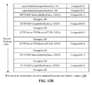
- FIGS. 7-13B are tables of embodiments of data record templates useful for tracking application or transport layer flows
- FIG. 14 is a table of an embodiment of a data record template useful for exporting system logs
- FIG. 15 is a flow chart of an embodiment of a method for tracking application layer flow via a multi-connection intermediary device
- FIG. 16 is a flow chart of an embodiment of a method for aggregating flow data records by session or transaction-specific characteristics
- FIG. 17 is a block diagram of an embodiment of a network environment for monitoring and recording application layer flows
- FIG. 18 is a flow chart of an embodiment of a method for monitoring and recording application layer flows
- FIG. 19A is a flow chart of an embodiment of a data recorder-side method for lightweight identification of flow information by application
- FIG. 19B is a flow chart of an embodiment of a data collector-side method for lightweight identification of flow information by application
- FIG. 19C is a table of an embodiment of a lightweight application identification template
- FIG. 20A is a signal flow diagram of an embodiment of source performance measurement
- FIG. 20B is a flow chart of an embodiment of a method of application performance measurement
- FIG. 20C is a table of an embodiment of an application load time record.
- FIG. 20D is a table of an embodiment of an application render time record.
- the network environment comprises one or more clients 102 a - 102 n (also generally referred to as local machine(s) 102 , or client(s) 102 ) in communication with one or more servers 106 a - 106 n (also generally referred to as server(s) 106 , or remote machine(s) 106 ) via one or more networks 104 , 104 ′ (generally referred to as network 104 ).
- a client 102 communicates with a server 106 via an appliance 200 .
- FIG. 1A shows a network 104 and a network 104 ′ between the clients 102 and the servers 106
- the networks 104 and 104 ′ can be the same type of network or different types of networks.
- the network 104 and/or the network 104 ′ can be a local-area network (LAN), such as a company Intranet, a metropolitan area network (MAN), or a wide area network (WAN), such as the Internet or the World Wide Web.
- LAN local-area network
- MAN metropolitan area network
- WAN wide area network
- network 104 ′ may be a private network and network 104 may be a public network.
- network 104 may be a private network and network 104 ′ a public network.
- networks 104 and 104 ′ may both be private networks.
- clients 102 may be located at a branch office of a corporate enterprise communicating via a WAN connection over the network 104 to the servers 106 located at a corporate data center.
- the network 104 and/or 104 ′ be any type and/or form of network and may include any of the following: a point to point network, a broadcast network, a wide area network, a local area network, a telecommunications network, a data communication network, a computer network, an ATM (Asynchronous Transfer Mode) network, a SONET (Synchronous Optical Network) network, a SDH (Synchronous Digital Hierarchy) network, a wireless network and a wireline network.
- the network 104 may comprise a wireless link, such as an infrared channel or satellite band.
- the topology of the network 104 and/or 104 ′ may be a bus, star, or ring network topology.
- the network 104 and/or 104 ′ and network topology may be of any such network or network topology as known to those ordinarily skilled in the art capable of supporting the operations described herein.
- the appliance 200 comprises any of the network devices manufactured by Citrix Systems, Inc. of Ft. Lauderdale Fla., referred to as Citrix NetScaler devices.
- the appliance 200 includes any of the product embodiments referred to as WebAccelerator and BigIP manufactured by F5 Networks, Inc. of Seattle, Wash.
- the appliance 205 includes any of the DX acceleration device platforms and/or the SSL VPN series of devices, such as SA 700, SA 2000, SA 4000, and SA 6000 devices manufactured by Juniper Networks, Inc. of Sunnyvale, Calif.
- the appliance 200 includes any application acceleration and/or security related appliances and/or software manufactured by Cisco Systems, Inc. of San Jose, Calif., such as the Cisco ACE Application Control Engine Module service software and network modules, and Cisco AVS Series Application Velocity System.
- the system may include multiple, logically-grouped servers 106 .
- the logical group of servers may be referred to as a server farm 38 .
- the serves 106 may be geographically dispersed.
- a farm 38 may be administered as a single entity.
- the server farm 38 comprises a plurality of server farms 38 .
- the server farm executes one or more applications on behalf of one or more clients 102 .
- the servers 106 within each farm 38 can be heterogeneous. One or more of the servers 106 can operate according to one type of operating system platform (e.g., WINDOWS NT, manufactured by Microsoft Corp. of Redmond, Wash.), while one or more of the other servers 106 can operate on according to another type of operating system platform (e.g., Unix or Linux).
- the servers 106 of each farm 38 do not need to be physically proximate to another server 106 in the same farm 38 .
- the group of servers 106 logically grouped as a farm 38 may be interconnected using a wide-area network (WAN) connection or medium-area network (MAN) connection.
- WAN wide-area network
- MAN medium-area network
- a farm 38 may include servers 106 physically located in different continents or different regions of a continent, country, state, city, campus, or room. Data transmission speeds between servers 106 in the farm 38 can be increased if the servers 106 are connected using a local-area network (LAN) connection or some form of direct connection.
- LAN local-area network
- a client 102 communicates with a server 106 .
- the client 102 communicates directly with one of the servers 106 in a farm 38 .
- the client 102 executes a program neighborhood application to communicate with a server 106 in a farm 38 .
- the server 106 provides the functionality of a master node.
- the client 102 communicates with the server 106 in the farm 38 through a network 104 . Over the network 104 , the client 102 can, for example, request execution of various applications hosted by the servers 106 a - 106 n in the farm 38 and receive output of the results of the application execution for display.
- only the master node provides the functionality required to identify and provide address information associated with a server 106 ′ hosting a requested application.
- a first appliance 200 may be deployed on a first network 104 and a second appliance 200 ′ on a second network 104 ′.
- a corporate enterprise may deploy a first appliance 200 at a branch office and a second appliance 200 ′ at a data center.
- the first appliance 200 and second appliance 200 ′ are deployed on the same network 104 or network 104 .
- a first appliance 200 may be deployed for a first server farm 38
- a second appliance 200 may be deployed for a second server farm 38 ′.
- a first appliance 200 may be deployed at a first branch office while the second appliance 200 ′ is deployed at a second branch office'.
- the first appliance 200 and second appliance 200 ′ work in cooperation or in conjunction with each other to accelerate network traffic or the delivery of application and data between a client and a server
- FIG. 1C another embodiment of a network environment deploying the appliance 200 with one or more other types of appliances, such as between one or more WAN optimization appliance 205 , 205 ′ is depicted.
- a first WAN optimization appliance 205 is shown between networks 104 and 104 ′ and a second WAN optimization appliance 205 ′ may be deployed between the appliance 200 and one or more servers 106 .
- a corporate enterprise may deploy a first WAN optimization appliance 205 at a branch office and a second WAN optimization appliance 205 ′ at a data center.
- the appliance 205 may be located on network 104 ′.
- the appliance 205 ′ may be located on network 104 .
- the appliance 205 ′ may be located on network 104 ′ or network 104 ′′. In some embodiments, the appliance 205 and 205 ′ are on the same network. In another embodiment, the appliance 205 and 205 ′ are on different networks. In another example, a first WAN optimization appliance 205 may be deployed for a first server farm 38 and a second WAN optimization appliance 205 ′ for a second server farm 38 ′
- the appliance 205 includes any of the WX and WXC WAN acceleration device platforms manufactured by Juniper Networks, Inc. of Sunnyvale, Calif. In some embodiments, the appliance 205 includes any of the steelhead line of WAN optimization appliances manufactured by Riverbed Technology of San Francisco, Calif. In other embodiments, the appliance 205 includes any of the WAN related devices manufactured by Expand Networks Inc. of Roseland, N.J. In some embodiments, the appliance 205 includes any of the WAN related appliances manufactured by Packeteer Inc. of Cupertino, Calif., such as the PacketShaper, iShared, and SkyX product embodiments provided by Packeteer. In yet another embodiment, the appliance 205 includes any WAN related appliances and/or software manufactured by Cisco Systems, Inc. of San Jose, Calif., such as the Cisco Wide Area Network Application Services software and network modules, and Wide Area Network engine appliances.
- the appliance 205 provides application and data acceleration services for branch-office or remote offices. In some embodiments, the appliance 205 includes optimization of Wide Area File Services (WAFS). In another embodiment, the appliance 205 accelerates the delivery of files, such as via the Common Internet File System (CIFS) protocol. In other embodiments, the appliance 205 provides caching in memory and/or storage to accelerate delivery of applications and data. In some embodiments, the appliance 205 provides compression of network traffic at any level of the network stack or at any protocol or network layer. In another embodiment, the appliance 205 provides transport layer protocol optimizations, flow control, performance enhancements or modifications and/or management to accelerate delivery of applications and data over a WAN connection. For example, In some embodiments, the appliance 205 provides Transport Control Protocol (TCP) optimizations. In other embodiments, the appliance 205 provides optimizations, flow control, performance enhancements or modifications and/or management for any session or application layer protocol.
- TCP Transport Control Protocol
- the appliance 205 encoded any type and form of data or information into custom or standard TCP and/or IP header fields or option fields of network packet to announce presence, functionality or capability to another appliance 205 ′.
- an appliance 205 ′ may communicate with another appliance 205 ′ using data encoded in both TCP and/or IP header fields or options.
- the appliance may use TCP option(s) or IP header fields or options to communicate one or more parameters to be used by the appliances 205 , 205 ′ in performing functionality, such as WAN acceleration, or for working in conjunction with each other.
- the appliance 200 preserves any of the information encoded in TCP and/or IP header and/or option fields communicated between appliances 205 and 205 ′.
- the appliance 200 may terminate a transport layer connection traversing the appliance 200 , such as a transport layer connection from between a client and a server traversing appliances 205 and 205 ′.
- the appliance 200 identifies and preserves any encoded information in a transport layer packet transmitted by a first appliance 205 via a first transport layer connection and communicates a transport layer packet with the encoded information to a second appliance 205 ′ via a second transport layer connection.
- the appliance 200 accelerates delivery of a computing environment 15 , or any portion thereof, to a client 102 . In some embodiments, the appliance 200 accelerates the delivery of the computing environment 15 by the application delivery system 190 . For example, the embodiments described herein may be used to accelerate delivery of a streaming application and data file processable by the application from a central corporate data center to a remote user location, such as a branch office of the company. In another embodiment, the appliance 200 accelerates transport layer traffic between a client 102 and a server 106 .
- the appliance 200 may provide acceleration techniques for accelerating any transport layer payload from a server 106 to a client 102 , such as: 1) transport layer connection pooling, 2) transport layer connection multiplexing, 3) transport control protocol buffering, 4) compression and 5) caching.
- the appliance 200 provides load balancing of servers 106 in responding to requests from clients 102 .
- the appliance 200 acts as a proxy or access server to provide access to the one or more servers 106 .
- the appliance 200 provides a secure virtual private network connection from a first network 104 of the client 102 to the second network 104 ′ of the server 106 , such as an SSL VPN connection.
- the appliance 200 provides application firewall security, control and management of the connection and communications between a client 102 and a server 106 .
- the server 106 executing the application delivery system 190 may also store or provide the application and data file.
- a first set of one or more servers 106 may execute the application delivery system 190
- a different server 106 n may store or provide the application and data file.
- each of the application delivery system 190 , the application, and data file may reside or be located on different servers.
- any portion of the application delivery system 190 may reside, execute or be stored on or distributed to the appliance 200 , or a plurality of appliances.
- the application delivery system 190 comprises any portion of the Citrix Access SuiteTM by Citrix Systems, Inc., such as the MetaFrame or Citrix Presentation ServerTM and/or any of the Microsoft® Windows Terminal Services manufactured by the Microsoft Corporation.
- the application delivery system 190 may deliver one or more applications to clients 102 or users via a remote-display protocol or otherwise via remote-based or server-based computing.
- the application delivery system 190 may deliver one or more applications to clients or users via steaming of the application.
- the application delivery system 190 includes a policy engine 195 for controlling and managing the access to, selection of application execution methods and the delivery of applications.
- the policy engine 195 determines the one or more applications a user or client 102 may access.
- the policy engine 195 determines how the application should be delivered to the user or client 102 , e.g., the method of execution.
- the application delivery system 190 provides a plurality of delivery techniques from which to select a method of application execution, such as a server-based computing, streaming or delivering the application locally to the client 120 for local execution.
- a client 102 requests execution of an application program and the application delivery system 190 comprising a server 106 selects a method of executing the application program.
- the server 106 receives credentials from the client 102 .
- the server 106 receives a request for an enumeration of available applications from the client 102 .
- the application delivery system 190 in response to the request or receipt of credentials, enumerates a plurality of application programs available to the client 102 .
- the application delivery system 190 receives a request to execute an enumerated application.
- the application delivery system 190 selects one of a predetermined number of methods for executing the enumerated application, for example, responsive to a policy of a policy engine.
- the application delivery system 190 may select a method of execution of the application enabling the client 102 to receive application-output data generated by execution of the application program on a server 106 .
- the application delivery system 190 may select a method of execution of the application enabling the local machine 10 to execute the application program locally after retrieving a plurality of application files comprising the application.
- the application delivery system 190 may select a method of execution of the application to stream the application via the network 104 to the client 102 .
- a client 102 may execute, operate or otherwise provide an application, which can be any type and/or form of software, program, or executable instructions such as any type and/or form of web browser, web-based client, client-server application, a thin-client computing client, an ActiveX control, or a Java applet, or any other type and/or form of executable instructions capable of executing on client 102 .
- the application may be a server-based or a remote-based application executed on behalf of the client 102 on a server 106 .
- the server 106 may display output to the client 102 using any thin-client or remote-display protocol, such as the Independent Computing Architecture (ICA) protocol manufactured by Citrix Systems, Inc. of Ft. Lauderdale, Fla.
- ICA Independent Computing Architecture
- the application can use any type of protocol and it can be, for example, an HTTP client, an FTP client, an Oscar client, or a Telnet client.
- the application comprises any type of software related to VoIP communications, such as a soft IP telephone.
- the application comprises any application related to real-time data communications, such as applications for streaming video and/or audio.
- the server 106 or a server farm 38 may be running one or more applications, such as an application providing a thin-client computing or remote display presentation application.
- the server 106 or server farm 38 executes as an application, any portion of the Citrix Access SuiteTM by Citrix Systems, Inc., such as the MetaFrame or Citrix Presentation ServerTM, and/or any of the Microsoft® Windows Terminal Services manufactured by the Microsoft Corporation.
- the application is an ICA client, developed by Citrix Systems, Inc. of Fort Lauderdale, Fla.
- the application includes a Remote Desktop (RDP) client, developed by Microsoft Corporation of Redmond, Wash.
- RDP Remote Desktop
- the server 106 may run an application, which for example, may be an application server providing email services such as Microsoft Exchange manufactured by the Microsoft Corporation of Redmond, Wash., a web or Internet server, or a desktop sharing server, or a collaboration server.
- any of the applications may comprise any type of hosted service or products, such as GoToMeetingTM provided by Citrix Online Division, Inc. of Santa Barbara, California, WebExTM provided by WebEx, Inc. of Santa Clara, Calif., or Microsoft Office Live Meeting provided by Microsoft Corporation of Redmond, Wash.
- an embodiment of the network environment may include a monitoring server 106 A.
- the monitoring server 106 A may include any type and form performance monitoring service 198 .
- the performance monitoring service 198 may include monitoring, measurement and/or management software and/or hardware, including data collection, aggregation, analysis, management and reporting.
- the performance monitoring service 198 includes one or more monitoring agents 197 .
- the monitoring agent 197 includes any software, hardware or combination thereof for performing monitoring, measurement and data collection activities on a device, such as a client 102 , server 106 or an appliance 200 , 205 .
- the monitoring agent 197 includes any type and form of script, such as Visual Basic script, or Javascript.
- the monitoring agent 197 executes transparently to any application and/or user of the device. In some embodiments, the monitoring agent 197 is installed and operated unobtrusively to the application or client. In yet another embodiment, the monitoring agent 197 is installed and operated without any instrumentation for the application or device.
- the monitoring agent 197 monitors, measures and collects data on a predetermined frequency. In other embodiments, the monitoring agent 197 monitors, measures and collects data based upon detection of any type and form of event. For example, the monitoring agent 197 may collect data upon detection of a request for a web page or receipt of an HTTP response. In another example, the monitoring agent 197 may collect data upon detection of any user input events, such as a mouse click. The monitoring agent 197 may report or provide any monitored, measured or collected data to the monitoring service 198 . In some embodiments, the monitoring agent 197 transmits information to the monitoring service 198 according to a schedule or a predetermined frequency. In another embodiment, the monitoring agent 197 transmits information to the monitoring service 198 upon detection of an event.
- the monitoring service 198 and/or monitoring agent 197 performs monitoring and performance measurement of any network resource or network infrastructure element, such as a client, server, server farm, appliance 200 , appliance 205 , or network connection. In some embodiments, the monitoring service 198 and/or monitoring agent 197 performs monitoring and performance measurement of any transport layer connection, such as a TCP or UDP connection. In another embodiment, the monitoring service 198 and/or monitoring agent 197 monitors and measures network latency. In yet one embodiment, the monitoring service 198 and/or monitoring agent 197 monitors and measures bandwidth utilization.
- the monitoring service 198 and/or monitoring agent 197 monitors and measures end-user response times. In some embodiments, the monitoring service 198 performs monitoring and performance measurement of an application. In another embodiment, the monitoring service 198 and/or monitoring agent 197 performs monitoring and performance measurement of any session or connection to the application. In some embodiments, the monitoring service 198 and/or monitoring agent 197 monitors and measures performance of a browser. In another embodiment, the monitoring service 198 and/or monitoring agent 197 monitors and measures performance of HTTP based transactions. In some embodiments, the monitoring service 198 and/or monitoring agent 197 monitors and measures performance of a Voice over IP (VoIP) application or session.
- VoIP Voice over IP
- the monitoring service 198 and/or monitoring agent 197 monitors and measures performance of a remote display protocol application, such as an ICA client or RDP client. In yet another embodiment, the monitoring service 198 and/or monitoring agent 197 monitors and measures performance of any type and form of streaming media. In still a further embodiment, the monitoring service 198 and/or monitoring agent 197 monitors and measures performance of a hosted application or a Software-As-A-Service (SaaS) delivery model.
- SaaS Software-As-A-Service
- the monitoring service 198 and/or monitoring agent 197 performs monitoring and performance measurement of one or more transactions, requests or responses related to application. In other embodiments, the monitoring service 198 and/or monitoring agent 197 monitors and measures any portion of an application layer stack, such as any .NET or J2EE calls. In some embodiments, the monitoring service 198 and/or monitoring agent 197 monitors and measures database or SQL transactions. In yet another embodiment, the monitoring service 198 and/or monitoring agent 197 monitors and measures any method, function or application programming interface (API) call.
- API application programming interface
- the monitoring service 198 and/or monitoring agent 197 measures and monitors memory usage for the application delivery system 190 , such as total memory usage, per user session and/or per process. In other embodiments, the monitoring service 198 and/or monitoring agent 197 measures and monitors CPU usage the application delivery system 190 , such as total CPU usage, per user session and/or per process. In another embodiments, the monitoring service 198 and/or monitoring agent 197 measures and monitors the time required to log-in to an application, a server, or the application delivery system, such as Citrix Presentation Server. In some embodiments, the monitoring service 198 and/or monitoring agent 197 measures and monitors the duration a user is logged into an application, a server, or the application delivery system 190 .
- the monitoring service 198 and/or monitoring agent 197 measures and monitors measures and monitors any type and form of server metrics. In some embodiments, the monitoring service 198 and/or monitoring agent 197 measures and monitors metrics related to system memory, CPU usage, and disk storage. In another embodiment, the monitoring service 198 and/or monitoring agent 197 measures and monitors metrics related to page faults, such as page faults per second. In other embodiments, the monitoring service 198 and/or monitoring agent 197 measures and monitors round-trip time metrics. In yet another embodiment, the monitoring service 198 and/or monitoring agent 197 measures and monitors metrics related to application crashes, errors and/or hangs.
- the central processing unit 101 is any logic circuitry that responds to and processes instructions fetched from the main memory unit 122 .
- the central processing unit is provided by a microprocessor unit, such as: those manufactured by Intel Corporation of Mountain View, Calif.; those manufactured by Motorola Corporation of Schaumburg, Ill.; those manufactured by Transmeta Corporation of Santa Clara, Calif.; the RS/6000 processor, those manufactured by International Business Machines of White Plains, N.Y.; or those manufactured by Advanced Micro Devices of Sunnyvale, Calif.
- the computing device 100 may be based on any of these processors, or any other processor capable of operating as described herein.
- the main memory 122 may be based on any of the above described memory chips, or any other available memory chips capable of operating as described herein.
- the processor 101 communicates with main memory 122 via a system bus 150 (described in more detail below).
- FIG. 1F depicts an embodiment of a computing device 100 in which the processor communicates directly with main memory 122 via a memory port 103 .
- the main memory 122 may be DRDRAM.
- FIG. 1F depicts an embodiment of a computer 100 in which the main processor 101 communicates directly with I/O device 130 b via HyperTransport, Rapid I/O, or InfiniBand.
- FIG. 1F also depicts an embodiment in which local busses and direct communication are mixed: the processor 101 communicates with I/O device 130 b using a local interconnect bus while communicating with I/O device 130 a directly.
- the computing device 100 may support any suitable installation device 116 , such as a floppy disk drive for receiving floppy disks such as 3.5-inch, 5.25-inch disks or ZIP disks, a CD-ROM drive, a CD-R/RW drive, a DVD-ROM drive, tape drives of various formats, USB device, hard-drive or any other device suitable for installing software and programs such as any client agent 120 , or portion thereof.
- the computing device 100 may further comprise a storage device 128 , such as one or more hard disk drives or redundant arrays of independent disks, for storing an operating system and other related software, and for storing application software programs such as any program related to the client agent 120 .
- any of the installation devices 116 could also be used as the storage device 128 .
- the operating system and the software can be run from a bootable medium, for example, a bootable CD, such as KNOPPIX®, a bootable CD for GNU/Linux that is available as a GNU/Linux distribution from knoppix.net.
- a bootable CD such as KNOPPIX®
- KNOPPIX® a bootable CD for GNU/Linux that is available as a GNU/Linux distribution from knoppix.net.
- I/O devices 130 a - 130 n may be present in the computing device 100 .
- Input devices include keyboards, mice, trackpads, trackballs, microphones, and drawing tablets.
- Output devices include video displays, speakers, inkjet printers, laser printers, and dye-sublimation printers.
- the I/O devices 130 may be controlled by an I/O controller 123 as shown in FIG. 1E .
- the I/O controller may control one or more I/O devices such as a keyboard 126 and a pointing device 127 , e.g., a mouse or optical pen.
- an I/O device may also provide storage 128 and/or an installation medium 116 for the computing device 100 .
- the computing device 100 may provide USB connections to receive handheld USB storage devices such as the USB Flash Drive line of devices manufactured by Twintech Industry, Inc. of Los Alamitos, California.
- the computing device 100 may comprise or be connected to multiple display devices 124 a - 124 n , which each may be of the same or different type and/or form.
- any of the I/O devices 130 a - 130 n and/or the I/O controller 123 may comprise any type and/or form of suitable hardware, software, or combination of hardware and software to support, enable or provide for the connection and use of multiple display devices 124 a - 124 n by the computing device 100 .
- the computing device 100 may include any type and/or form of video adapter, video card, driver, and/or library to interface, communicate, connect or otherwise use the display devices 124 a - 124 n .
- a video adapter may comprise multiple connectors to interface to multiple display devices 124 a - 124 n .
- the computing device 100 may include multiple video adapters, with each video adapter connected to one or more of the display devices 124 a - 124 n .
- any portion of the operating system of the computing device 100 may be configured for using multiple displays 124 a - 124 n .
- one or more of the display devices 124 a - 124 n may be provided by one or more other computing devices, such as computing devices 100 a and 100 b connected to the computing device 100 , for example, via a network.
- These embodiments may include any type of software designed and constructed to use another computer's display device as a second display device 124 a for the computing device 100 .
- a computing device 100 may be configured to have multiple display devices 124 a - 124 n.
- an I/O device 130 may be a bridge 170 between the system bus 150 and an external communication bus, such as a USB bus, an Apple Desktop Bus, an RS-232 serial connection, a SCSI bus, a FireWire bus, a FireWire 800 bus, an Ethernet bus, an AppleTalk bus, a Gigabit Ethernet bus, an Asynchronous Transfer Mode bus, a HIPPI bus, a Super HIPPI bus, a SerialPlus bus, a SCI/LAMP bus, a FibreChannel bus, or a Serial Attached small computer system interface bus.
- an external communication bus such as a USB bus, an Apple Desktop Bus, an RS-232 serial connection, a SCSI bus, a FireWire bus, a FireWire 800 bus, an Ethernet bus, an AppleTalk bus, a Gigabit Ethernet bus, an Asynchronous Transfer Mode bus, a HIPPI bus, a Super HIPPI bus, a SerialPlus bus, a SCI/LAMP bus, a FibreChannel bus, or
- a computing device 100 of the sort depicted in FIGS. 1E and 1F typically operate under the control of operating systems, which control scheduling of tasks and access to system resources.
- the computing device 100 can be running any operating system such as any of the versions of the Microsoft® Windows operating systems, the different releases of the Unix and Linux operating systems, any version of the Mac OS® for Macintosh computers, any embedded operating system, any real-time operating system, any open source operating system, any proprietary operating system, any operating systems for mobile computing devices, or any other operating system capable of running on the computing device and performing the operations described herein.
- Typical operating systems include: WINDOWS 3.x, WINDOWS 95, WINDOWS 98, WINDOWS 2000, WINDOWS NT 3.51, WINDOWS NT 4.0, WINDOWS CE, and WINDOWS XP, all of which are manufactured by Microsoft Corporation of Redmond, Wash.; MacOS, manufactured by Apple Computer of Cupertino, California; OS/2, manufactured by International Business Machines of Armonk, N.Y.; and Linux, a freely-available operating system distributed by Caldera Corp. of Salt Lake City, Utah, or any type and/or form of a Unix operating system, among others.
- the computing device 100 may have different processors, operating systems, and input devices consistent with the device.
- the computer 100 is a Treo 180, 270, 1060, 600 or 650 smart phone manufactured by Palm, Inc.
- the Treo smart phone is operated under the control of the PalmOS operating system and includes a stylus input device as well as a five-way navigator device.
- the computing device 100 can be any workstation, desktop computer, laptop or notebook computer, server, handheld computer, mobile telephone, any other computer, or other form of computing or telecommunications device that is capable of communication and that has sufficient processor power and memory capacity to perform the operations described herein.
- the computing device 100 may comprise multiple processors and may provide functionality for simultaneous execution of instructions or for simultaneous execution of one instruction on more than one piece of data.
- the computing device 100 may comprise a parallel processor with one or more cores.
- the computing device 100 is a shared memory parallel device, with multiple processors and/or multiple processor cores, accessing all available memory as a single global address space.
- the computing device 100 is a distributed memory parallel device with multiple processors each accessing local memory only.
- the computing device 100 has both some memory which is shared and some memory which can only be accessed by particular processors or subsets of processors.
- the computing device 100 such as a multi-core microprocessor, combines two or more independent processors into a single package, often a single integrated circuit (IC).
- the computing device 100 includes a chip having a CELL BROADBAND ENGINE architecture and including a Power processor element and a plurality of synergistic processing elements, the Power processor element and the plurality of synergistic processing elements linked together by an internal high speed bus, which may be referred to as an element interconnect bus.
- the processors provide functionality for execution of a single instruction simultaneously on multiple pieces of data (SIMD). In other embodiments, the processors provide functionality for execution of multiple instructions simultaneously on multiple pieces of data (MIMD). In still other embodiments, the processor may use any combination of SIMD and MIMD cores in a single device.
- the computing device 100 may comprise a graphics processing unit.
- the computing device 100 includes at least one central processing unit 101 and at least one graphics processing unit.
- the computing device 100 includes at least one parallel processing unit and at least one graphics processing unit.
- the computing device 100 includes a plurality of processing units of any type, one of the plurality of processing units comprising a graphics processing unit.
- FIG. 2A illustrates an example embodiment of the appliance 200 .
- the architecture of the appliance 200 in FIG. 2A is provided by way of illustration only and is not intended to be limiting.
- appliance 200 comprises a hardware layer 206 and a software layer divided into a user space 202 and a kernel space 204 .
- Hardware layer 206 provides the hardware elements upon which programs and services within kernel space 204 and user space 202 are executed. Hardware layer 206 also provides the structures and elements which allow programs and services within kernel space 204 and user space 202 to communicate data both internally and externally with respect to appliance 200 . As shown in FIG. 2 , the hardware layer 206 includes a processing unit 262 for executing software programs and services, a memory 264 for storing software and data, network ports 266 for transmitting and receiving data over a network, and an encryption processor 260 for performing functions related to Secure Sockets Layer processing of data transmitted and received over the network. In some embodiments, the central processing unit 262 may perform the functions of the encryption processor 260 in a single processor.
- the hardware layer 206 may comprise multiple processors for each of the processing unit 262 and the encryption processor 260 .
- the processor 262 may include any of the processors 101 described above in connection with FIGS. 1E and 1F .
- the appliance 200 comprises a first processor 262 and a second processor 262 ′.
- the processor 262 or 262 ′ comprises a multi-core processor.
- the kernel space 204 is reserved for running the kernel 230 , including any device drivers, kernel extensions or other kernel related software.
- the kernel 230 is the core of the operating system, and provides access, control, and management of resources and hardware-related elements of the application 104 .
- the kernel space 204 also includes a number of network services or processes working in conjunction with a cache manager 232 , sometimes also referred to as the integrated cache, the benefits of which are described in detail further herein. Additionally, the embodiment of the kernel 230 will depend on the embodiment of the operating system installed, configured, or otherwise used by the device 200 .
- running the encryption engine 234 in kernel mode improves encryption performance by moving encryption and decryption operations to the kernel, thereby reducing the number of transitions between the memory space or a kernel thread in kernel mode and the memory space or a thread in user mode.
- data obtained in kernel mode may not need to be passed or copied to a process or thread running in user mode, such as from a kernel level data structure to a user level data structure.
- the number of context switches between kernel mode and user mode are also reduced. Additionally, synchronization of and communications between any of the components or processes 232 , 240 , 235 , 236 and 238 can be performed more efficiently in the kernel space 204 .
- the kernel-level data structure may comprise any interface and/or data accessible via the kernel space 204 related to the network stack 267 , network traffic or packets received or transmitted by the network stack 267 .
- the kernel-level data structure may be used by any of the components or processes 232 , 240 , 234 , 236 and 238 to perform the desired operation of the component or process.
- a component 232 , 240 , 234 , 236 and 238 is running in kernel mode 204 when using the kernel-level data structure, while in another embodiment, the component 232 , 240 , 234 , 236 and 238 is running in user mode when using the kernel-level data structure.
- the kernel-level data structure may be copied or passed to a second kernel-level data structure, or any desired user-level data structure.
- the cache manager 232 may comprise software, hardware or any combination of software and hardware to provide cache access, control and management of any type and form of content, such as objects or dynamically generated objects served by the originating servers 106 .
- the data, objects or content processed and stored by the cache manager 232 may comprise data in any format, such as a markup language, or communicated via any protocol.
- the cache manager 232 duplicates original data stored elsewhere or data previously computed, generated or transmitted, in which the original data may require longer access time to fetch, compute or otherwise obtain relative to reading a cache memory element. Once the data is stored in the cache memory element, future use can be made by accessing the cached copy rather than refetching or recomputing the original data, thereby reducing the access time.
- the encryption engine 234 comprises any logic, business rules, functions or operations for handling the processing of any security related protocol, such as SSL or TLS, or any function related thereto.
- the encryption engine 234 encrypts and decrypts network packets, or any portion thereof, communicated via the appliance 200 .
- the encryption engine 234 may also setup or establish SSL or TLS connections on behalf of the client 102 a - 102 n , server 106 a - 106 n , or appliance 200 . As such, the encryption engine 234 provides offloading and acceleration of SSL processing.
- encryption engine 234 is configured to perform SSL processing of packets
- policy engine 236 is configured to perform functions related to traffic management such as request-level content switching and request-level cache redirection
- multi-protocol compression logic 238 is configured to perform functions related to compression and decompression of data.
- any of the logic, functions, or operations of the encryption engine 234 , cache manager 232 , policy engine 236 and multi-protocol compression logic 238 may be performed responsive to the packet processing timer 242 and/or the packet engine 240 . Therefore, any of the logic, functions, or operations of the encryption engine 234 , cache manager 232 , policy engine 236 and multi-protocol compression logic 238 may be performed at the granularity of time intervals provided via the packet processing timer 242 , for example, at a time interval of less than or equal to 10 ms.
- the cache manager 232 may perform invalidation of any cached objects responsive to the high speed layer 2-7 integrated packet engine 240 and/or the packet processing timer 242 .
- the expiry or invalidation time of a cached object can be set to the same order of granularity as the time interval of the packet processing timer 242 , such as at every 10 ms.
- the GUI 210 or CLI 212 can comprise code running in user space 202 or kernel space 204 .
- the GUI 210 may be any type and form of graphical user interface and may be presented via text, graphical or otherwise, by any type of program or application, such as a browser.
- the CLI 212 may be any type and form of command line or text-based interface, such as a command line provided by the operating system.
- the CLI 212 may comprise a shell, which is a tool to enable users to interact with the operating system.
- the CLI 212 may be provided via a bash, csh, tcsh, or ksh type shell.
- the shell services 214 comprises the programs, services, tasks, processes or executable instructions to support interaction with the appliance 200 or operating system by a user via the GUI 210 and/or CLI 212 .
- the appliance 200 comprises one or more virtual servers or virtual internet protocol servers, referred to as a vServer, VIP server, or just VIP 275 a - 275 n (also referred herein as vServer 275 ).
- the vServer 275 receives, intercepts or otherwise processes communications between a client 102 and a server 106 in accordance with the configuration and operations of the appliance 200 .
- the service 275 may comprise any program, application, process, task or set of executable instructions capable of connecting to and communicating to the appliance 200 , client 102 or vServer 275 .
- the service 275 may comprise a web server, http server, ftp, email or database server.
- the service 270 is a daemon process or network driver for listening, receiving and/or sending communications for an application, such as email, database or an enterprise application.
- the service 270 may communicate on a specific IP address, or IP address and port.
- the policies of the policy engine have conditions upon which the policy is applied based on any content of the communication, such as internet protocol address, port, protocol type, header or fields in a packet, or the context of the communication, such as user, group of the user, vServer 275 , transport layer connection, and/or identification or attributes of the client 102 or server 106 .
- the appliance 200 communicates or interfaces with the policy engine 236 to determine authentication and/or authorization of a remote user or a remote client 102 to access the computing environment 15 , application, and/or data file from a server 106 . In another embodiment, the appliance 200 communicates or interfaces with the policy engine 236 to determine authentication and/or authorization of a remote user or a remote client 102 to have the application delivery system 190 deliver one or more of the computing environment 15 , application, and/or data file.
- the appliance 200 establishes a VPN or SSL VPN connection based on the policy engine's 236 authentication and/or authorization of a remote user or a remote client 102
- the appliance 200 controls the flow of network traffic and communication sessions based on policies of the policy engine 236 .
- the appliance 200 may control the access to a computing environment 15 , application or data file based on the policy engine 236 .
- the vServer 275 establishes a transport layer connection, such as a TCP or UDP connection with a client 102 via the client agent 120 . In some embodiments, the vServer 275 listens for and receives communications from the client 102 . In other embodiments, the vServer 275 establishes a transport layer connection, such as a TCP or UDP connection with a client server 106 . In some embodiments, the vServer 275 establishes the transport layer connection to an internet protocol address and port of a server 270 running on the server 106 . In another embodiment, the vServer 275 associates a first transport layer connection to a client 102 with a second transport layer connection to the server 106 . In some embodiments, a vServer 275 establishes a pool of transport layer connections to a server 106 and multiplexes client requests via the pooled transport layer connections.
- a transport layer connection such as a TCP or UDP connection with a client 102 via the
- the appliance 200 provides one or more of the following acceleration techniques 288 to communications between the client 102 and server 106 : 1) compression; 2) decompression; 3) Transmission Control Protocol pooling; 4) Transmission Control Protocol multiplexing; 5) Transmission Control Protocol buffering; and 6) caching.
- the appliance 200 relieves servers 106 of much of the processing load caused by repeatedly opening and closing transport layers connections to clients 102 by opening one or more transport layer connections with each server 106 and maintaining these connections to allow repeated data accesses by clients via the Internet. This technique is referred to herein as “connection pooling”.
- the appliance 200 in order to seamlessly splice communications from a client 102 to a server 106 via a pooled transport layer connection, the appliance 200 translates or multiplexes communications by modifying sequence number and acknowledgment numbers at the transport layer protocol level. This is referred to as “connection multiplexing”. In some embodiments, no application layer protocol interaction is required. For example, in the case of an in-bound packet (that is, a packet received from a client 102 ), the source network address of the packet is changed to that of an output port of appliance 200 , and the destination network address is changed to that of the intended server.
- an in-bound packet that is, a packet received from a client 102
- the source network address of the packet is changed to that of an output port of appliance 200
- the destination network address is changed to that of the intended server.
- the source network address is changed from that of the server 106 to that of an output port of appliance 200 and the destination address is changed from that of appliance 200 to that of the requesting client 102 .
- the sequence numbers and acknowledgment numbers of the packet are also translated to sequence numbers and acknowledgement numbers expected by the client 102 on the appliance's 200 transport layer connection to the client 102 .
- the packet checksum of the transport layer protocol is recalculated to account for these translations.
- the appliance 200 acts as a Domain Name Service (DNS) resolver or otherwise provides resolution of a DNS request from clients 102 .
- DNS Domain Name Service
- the appliance intercepts a DNS request transmitted by the client 102 .
- the appliance 200 responds to a client's DNS request with an IP address of or hosted by the appliance 200 .
- the client 102 transmits network communication for the domain name to the appliance 200 .
- the appliance 200 responds to a client's DNS request with an IP address of or hosted by a second appliance 200 ′.
- the appliance 200 responds to a client's DNS request with an IP address of a server 106 determined by the appliance 200 .
- the appliance 200 provides application firewall functionality 290 for communications between the client 102 and server 106 .
- the policy engine 236 provides rules for detecting and blocking illegitimate requests.
- the application firewall 290 protects against denial of service (DoS) attacks.
- the appliance inspects the content of intercepted requests to identify and block application-based attacks.
- DoS denial of service
- the rules/policy engine 236 comprises one or more application firewall or security control policies for providing protections against various classes and types of web or Internet based vulnerabilities, such as one or more of the following: 1) buffer overflow, 2) CGI-BIN parameter manipulation, 3) form/hidden field manipulation, 4) forceful browsing, 5) cookie or session poisoning, 6) broken access control list (ACLs) or weak passwords, 7) cross-site scripting (XSS), 8) command injection, 9) SQL injection, 10) error triggering sensitive information leak, 11) insecure use of cryptography, 12) server misconfiguration, 13) back doors and debug options, 14) website defacement, 15) platform or operating systems vulnerabilities, and 16) zero-day exploits.
- application firewall or security control policies for providing protections against various classes and types of web or Internet based vulnerabilities, such as one or more of the following: 1) buffer overflow, 2) CGI-BIN parameter manipulation, 3) form/hidden field manipulation, 4) forceful browsing, 5) cookie or session poisoning, 6) broken access control list (
- the application firewall 290 protects any confidential information contained in the network communication.
- the application firewall 290 may inspect or analyze any network communication in accordance with the rules or polices of the engine 236 to identify any confidential information in any field of the network packet.
- the application firewall 290 identifies in the network communication one or more occurrences of a credit card number, password, social security number, name, patient code, contact information, and age.
- the encoded portion of the network communication may comprise these occurrences or the confidential information. Based on these occurrences,
- the application firewall 290 may take a policy action on the network communication, such as prevent transmission of the network communication.
- the application firewall 290 may rewrite, remove or otherwise mask such identified occurrence or confidential information.
- the appliance 200 may include a performance monitoring agent 197 as discussed above in conjunction with FIG. 1D .
- the appliance 200 receives the monitoring agent 197 from the monitoring service 198 or monitoring server 106 as depicted in FIG. 1D .
- the appliance 200 stores the monitoring agent 197 in storage, such as disk, for delivery to any client or server in communication with the appliance 200 .
- the appliance 200 transmits the monitoring agent 197 to a client upon receiving a request to establish a transport layer connection.
- the appliance 200 transmits the monitoring agent 197 upon establishing the transport layer connection with the client 102 .
- the appliance 200 transmits the monitoring agent 197 to the client upon intercepting or detecting a request for a web page. In yet another embodiment, the appliance 200 transmits the monitoring agent 197 to a client or a server in response to a request from the monitoring server 198 . In some embodiments, the appliance 200 transmits the monitoring agent 197 to a second appliance 200 ′ or appliance 205 .
- the appliance 200 executes the monitoring agent 197 .
- the monitoring agent 197 measures and monitors the performance of any application, program, process, service, task or thread executing on the appliance 200 .
- the monitoring agent 197 may monitor and measure performance and operation of vServers 275 A- 275 N.
- the monitoring agent 197 measures and monitors the performance of any transport layer connections of the appliance 200 .
- the monitoring agent 197 measures and monitors the performance of any user sessions traversing the appliance 200 .
- the monitoring agent 197 measures and monitors the performance of any virtual private network connections and/or sessions traversing the appliance 200 , such an SSL VPN session.
- the monitoring agent 197 measures and monitors the memory, CPU and disk usage and performance of the appliance 200 . In yet another embodiment, the monitoring agent 197 measures and monitors the performance of any acceleration technique 288 performed by the appliance 200 , such as SSL offloading, connection pooling and multiplexing, caching, and compression. In some embodiments, the monitoring agent 197 measures and monitors the performance of any load balancing and/or content switching 284 performed by the appliance 200 . In other embodiments, the monitoring agent 197 measures and monitors the performance of application firewall 290 protection and processing performed by the appliance 200 .
- any acceleration technique 288 such as SSL offloading, connection pooling and multiplexing, caching, and compression.
- the monitoring agent 197 measures and monitors the performance of any load balancing and/or content switching 284 performed by the appliance 200 . In other embodiments, the monitoring agent 197 measures and monitors the performance of application firewall 290 protection and processing performed by the appliance 200 .
- the client 102 includes a client agent 120 for establishing and exchanging communications with the appliance 200 and/or server 106 via a network 104 .
- the client 102 operates on computing device 100 having an operating system with a kernel mode 302 and a user mode 303 , and a network stack 310 with one or more layers 310 a - 310 b .
- the client 102 may have installed and/or execute one or more applications.
- one or more applications may communicate via the network stack 310 to a network 104 .
- One of the applications such as a web browser, may also include a first program 322 .
- the first program 322 may be used in some embodiments to install and/or execute the client agent 120 , or any portion thereof.
- the client agent 120 includes an interception mechanism, or interceptor 350 , for intercepting network communications from the network stack 310 from the one or more applications.
- the network stack 310 of the client 102 may comprise any type and form of software, or hardware, or any combinations thereof, for providing connectivity to and communications with a network.
- the network stack 310 comprises a software implementation for a network protocol suite.
- the network stack 310 may comprise one or more network layers, such as any networks layers of the Open Systems Interconnection (OSI) communications model as those skilled in the art recognize and appreciate.
- OSI Open Systems Interconnection
- the network stack 310 may comprise any type and form of protocols for any of the following layers of the OSI model: 1) physical link layer, 2) data link layer, 3) network layer, 4) transport layer, 5) session layer, 6) presentation layer, and 7) application layer.
- the network stack 310 may comprise a transport control protocol (TCP) over the network layer protocol of the internet protocol (IP), generally referred to as TCP/IP.
- TCP/IP transport control protocol
- IP internet protocol
- the TCP/IP protocol may be carried over the Ethernet protocol, which may comprise any of the family of IEEE wide-area-network (WAN) or local-area-network (LAN) protocols, such as those protocols covered by the IEEE 802.3.
- the network stack 310 comprises any type and form of a wireless protocol, such as IEEE 802.11 and/or mobile internet protocol.
- any TCP/IP based protocol may be used, including Messaging Application Programming Interface (MAPI) (email), File Transfer Protocol (FTP), HyperText Transfer Protocol (HTTP), Common Internet File System (CIFS) protocol (file transfer), Independent Computing Architecture (ICA) protocol, Remote Desktop Protocol (RDP), Wireless Application Protocol (WAP), Mobile IP protocol, and Voice Over IP (VoIP) protocol.
- MAPI Messaging Application Programming Interface
- FTP File Transfer Protocol
- HTTP HyperText Transfer Protocol
- CIFS Common Internet File System
- ICA Independent Computing Architecture
- RDP Remote Desktop Protocol
- WAP Wireless Application Protocol
- VoIP Voice Over IP
- the network stack 310 may include one or more network drivers supporting the one or more layers, such as a TCP driver or a network layer driver.
- the network drivers may be included as part of the operating system of the computing device 100 or as part of any network interface cards or other network access components of the computing device 100 .
- any of the network drivers of the network stack 310 may be customized, modified or adapted to provide a custom or modified portion of the network stack 310 in support of any of the techniques described herein.
- the acceleration program 302 is designed and constructed to operate with or work in conjunction with the network stack 310 installed or otherwise provided by the operating system of the client 102 .
- the network stack 310 comprises any type and form of interfaces for receiving, obtaining, providing or otherwise accessing any information and data related to network communications of the client 102 .
- an interface to the network stack 310 comprises an application programming interface (API).
- API application programming interface
- the interface may also comprise any function call, hooking or filtering mechanism, event or call back mechanism, or any type of interfacing technique.
- the network stack 310 via the interface may receive or provide any type and form of data structure, such as an object, related to functionality or operation of the network stack 310 .
- the data structure may comprise information and data related to a network packet or one or more network packets.
- some portions of the network stack 310 may execute or operate in kernel-mode 302 , for example, the data link or network layer, while other portions execute or operate in user-mode 303 , such as an application layer of the network stack 310 .
- a first portion 310 a of the network stack may provide user-mode access to the network stack 310 to an application while a second portion 310 a of the network stack 310 provides access to a network.
- a first portion 310 a of the network stack may comprise one or more upper layers of the network stack 310 , such as any of layers 5-7.
- a second portion 310 b of the network stack 310 comprises one or more lower layers, such as any of layers 1-4.
- the client agent 120 may comprise two agents 120 and 120 ′.
- a first agent 120 may comprise an interceptor 350 operating at the network layer of the network stack 310 .
- the first agent 120 intercepts network layer requests such as Internet Control Message Protocol (ICMP) requests (e.g., ping and traceroute).
- ICMP Internet Control Message Protocol
- the second agent 120 ′ may operate at the transport layer and intercept transport layer communications.
- the first agent 120 intercepts communications at one layer of the network stack 210 and interfaces with or communicates the intercepted communication to the second agent 120 ′.
- the client agent 120 and/or interceptor may operate at or interface with the network stack 310 in a manner transparent to any application, a user of the client 102 , and any other computing device, such as a server, in communications with the client 102 .
- the client agent 120 and/or interceptor 350 may be installed and/or executed on the client 102 in a manner without modification of an application.
- the user of the client 102 or a computing device in communications with the client 102 are not aware of the existence, execution or operation of the client agent 120 and/or interceptor 350 .
- the client 102 decompresses, unpackages or unarchives the application files.
- the streaming client 306 dynamically installs the application, or portion thereof, and executes the application.
- the streaming client 306 may be an executable program.
- the streaming client 306 may be able to launch another executable program.
- the first program 322 obtains, downloads, or receives the client agent 120 via the network from another computing device.
- the first program 322 is an installer program or a plug and play manager for installing programs, such as network drivers, on the operating system of the client 102 .
- a computing device 100 includes a hypervisor layer, a virtualization layer, and a hardware layer.
- the hypervisor layer includes a hypervisor 401 (also referred to as a virtualization manager) that allocates and manages access to a number of physical resources in the hardware layer (e.g., the processor(s) 421 , and disk(s) 428 ) by at least one virtual machine executing in the virtualization layer.
- the virtualization layer includes at least one operating system 410 and a plurality of virtual resources allocated to the at least one operating system 410 .
- Virtual resources may include, without limitation, a plurality of virtual processors 432 a , 432 b , 432 c (generally 432 ), and virtual disks 442 a , 442 b , 442 c (generally 442 ), as well as virtual resources such as virtual memory and virtual network interfaces.
- the plurality of virtual resources and the operating system 410 may be referred to as a virtual machine 406 .
- a virtual machine 406 may include a control operating system 405 in communication with the hypervisor 401 and used to execute applications for managing and configuring other virtual machines on the computing device 100 .
- a hypervisor 401 may provide virtual resources to an operating system in any manner which simulates the operating system having access to a physical device.
- a hypervisor 401 may provide virtual resources to any number of guest operating systems 410 a , 410 b (generally 410 ).
- a computing device 100 executes one or more types of hypervisors.
- hypervisors may be used to emulate virtual hardware, partition physical hardware, virtualize physical hardware, and execute virtual machines that provide access to computing environments.
- Hypervisors may include those manufactured by VMWare, Inc., of Palo Alto, Calif.; the XEN hypervisor, an open source product whose development is overseen by the open source Xen.org community; HyperV, VirtualServer or virtual PC hypervisors provided by Microsoft, or others.
- a computing device 100 executing a hypervisor that creates a virtual machine platform on which guest operating systems may execute is referred to as a host server.
- the computing device 100 is a XEN SERVER provided by Citrix Systems, Inc., of Fort Lauderdale, Fla.
- a hypervisor 401 executes within an operating system executing on a computing device.
- a computing device executing an operating system and a hypervisor 401 may be said to have a host operating system (the operating system executing on the computing device), and a guest operating system (an operating system executing within a computing resource partition provided by the hypervisor 401 ).
- a hypervisor 401 interacts directly with hardware on a computing device, instead of executing on a host operating system.
- the hypervisor 401 may be said to be executing on “bare metal,” referring to the hardware comprising the computing device.
- a hypervisor 401 may create a virtual machine 406 a - c (generally 406 ) in which an operating system 410 executes.
- the hypervisor 401 loads a virtual machine image to create a virtual machine 406 .
- the hypervisor 401 executes an operating system 410 within the virtual machine 406 .
- the virtual machine 406 executes an operating system 410 .
- the hypervisor 401 controls processor scheduling and memory partitioning for a virtual machine 406 executing on the computing device 100 . In one of these embodiments, the hypervisor 401 controls the execution of at least one virtual machine 406 . In another of these embodiments, the hypervisor 401 presents at least one virtual machine 406 with an abstraction of at least one hardware resource provided by the computing device 100 . In other embodiments, the hypervisor 401 controls whether and how physical processor capabilities are presented to the virtual machine 406 .
- a control operating system 405 may execute at least one application for managing and configuring the guest operating systems.
- the control operating system 405 may execute an administrative application, such as an application including a user interface providing administrators with access to functionality for managing the execution of a virtual machine, including functionality for executing a virtual machine, terminating an execution of a virtual machine, or identifying a type of physical resource for allocation to the virtual machine.
- the hypervisor 401 executes the control operating system 405 within a virtual machine 406 created by the hypervisor 401 .
- the control operating system 405 executes in a virtual machine 406 that is authorized to directly access physical resources on the computing device 100 .
- control operating system 405 executes in a virtual machine 406 that is authorized to interact with at least one guest operating system 410 .
- a guest operating system 410 communicates with the control operating system 405 via the hypervisor 401 in order to request access to a disk or a network.
- the guest operating system 410 and the control operating system 405 may communicate via a communication channel established by the hypervisor 401 , such as, for example, via a plurality of shared memory pages made available by the hypervisor 401 .
- the control operating system 405 includes a tools stack 404 .
- a tools stack 404 provides functionality for interacting with the hypervisor 401 , communicating with other control operating systems 405 (for example, on a second computing device 100 b ), or managing virtual machines 406 b , 406 c on the computing device 100 .
- the tools stack 404 includes customized applications for providing improved management functionality to an administrator of a virtual machine farm.
- at least one of the tools stack 404 and the control operating system 405 include a management API that provides an interface for remotely configuring and controlling virtual machines 406 running on a computing device 100 .
- the control operating system 405 communicates with the hypervisor 401 through the tools stack 404 .
- the hypervisor 401 executes a guest operating system 410 within a virtual machine 406 created by the hypervisor 401 .
- the guest operating system 410 provides a user of the computing device 100 with access to resources within a computing environment.
- a resource includes a program, an application, a document, a file, a plurality of applications, a plurality of files, an executable program file, a desktop environment, a computing environment, or other resource made available to a user of the computing device 100 .
- the resource may be delivered to the computing device 100 via a plurality of access methods including, but not limited to, conventional installation directly on the computing device 100 , delivery to the computing device 100 via a method for application streaming, delivery to the computing device 100 of output data generated by an execution of the resource on a second computing device 100 ′ and communicated to the computing device 100 via a presentation layer protocol, delivery to the computing device 100 of output data generated by an execution of the resource via a virtual machine executing on a second computing device 100 ′, or execution from a removable storage device connected to the computing device 100 , such as a USB device, or via a virtual machine executing on the computing device 100 and generating output data.
- the computing device 100 transmits output data generated by the execution of the resource to another computing device 100 ′.
- the guest operating system 410 in conjunction with the virtual machine on which it executes, forms a paravirtualized virtual machine, which is aware that it is a virtual machine; such a machine may be referred to as a “Domain U PV virtual machine”.
- a paravirtualized machine includes additional drivers that a fully-virtualized machine does not include.
- the paravirtualized machine includes the network back-end driver and the block back-end driver included in a control operating system 405 , as described above.
- FIG. 4B a block diagram depicts one embodiment of a plurality of networked computing devices in a system in which at least one physical host executes a virtual machine.
- the system includes a management component 404 and a hypervisor 401 .
- the system includes a plurality of computing devices 100 , a plurality of virtual machines 406 , a plurality of hypervisors 401 , a plurality of management components referred to variously as tools stacks 404 or management components 404 , and a physical resource 421 , 428 .
- the plurality of physical machines 100 may each be provided as computing devices 100 , described above in connection with FIGS. 1E-1H and 4A .
- a physical disk 428 is provided by a computing device 100 and stores at least a portion of a virtual disk 442 .
- a virtual disk 442 is associated with a plurality of physical disks 428 .
- one or more computing devices 100 may exchange data with one or more of the other computing devices 100 regarding processors and other physical resources available in a pool of resources, allowing a hypervisor to manage a pool of resources distributed across a plurality of physical computing devices.
- a computing device 100 on which a virtual machine 406 executes is referred to as a physical host 100 or as a host machine 100 .
- the management component 404 a is referred to as a pool management component 404 a .
- a management operating system 405 a which may be referred to as a control operating system 405 a , includes the management component.
- the management component is referred to as a tools stack. In one of these embodiments, the management component is the tools stack 404 described above in connection with FIG. 4A .
- the management component 404 provides a user interface for receiving, from a user such as an administrator, an identification of a virtual machine 406 to provision and/or execute.
- the management component 404 provides a user interface for receiving, from a user such as an administrator, the request for migration of a virtual machine 406 b from one physical machine 100 to another.
- the management component 404 a identifies a computing device 100 b on which to execute a requested virtual machine 406 d and instructs the hypervisor 401 b on the identified computing device 100 b to execute the identified virtual machine; such a management component may be referred to as a pool management component.
- any of the functionality and/or embodiments of the appliance 200 may be deployed in any embodiment of the virtualized environment described above in connection with FIGS. 4A and 4B .
- the functionality of the application delivery controller may be deployed in a virtualized environment 400 on any computing device 100 , such as a client 102 , server 106 or appliance 200 .
- FIG. 4C a diagram of an embodiment of a virtual appliance 450 operating on a hypervisor 401 of a server 106 is depicted.
- the virtual appliance 450 may provide functionality for availability, performance, offload and security.
- the virtual appliance may perform load balancing between layers 4 and 7 of the network and may also perform intelligent service health monitoring.
- the virtual appliance may perform caching and compression.
- the virtual appliance may perform connection multiplexing and pooling and/or SSL processing.
- the virtual appliance may perform any of the application firewall functionality and SSL VPN function of appliance 200 .
- any of the modules of the appliance 200 as described in connection with FIG. 2A may be packaged, combined, designed or constructed in a form of the virtualized appliance delivery controller 450 deployable as one or more software modules or components executable in a virtualized environment 300 or non-virtualized environment on any server, such as an off the shelf server.
- the virtual appliance may be provided in the form of an installation package to install on a computing device.
- any of the cache manager 232 , policy engine 236 , compression 238 , encryption engine 234 , packet engine 240 , GUI 210 , CLI 212 , shell services 214 and health monitoring programs 216 may be designed and constructed as a software component or module to run on any operating system of a computing device and/or of a virtualized environment 300 .
- the virtualized appliance 400 may use any of these resources as provided by the virtualized environment 400 or as otherwise available on the server 106 .
- vServer 275 Any of the vServer 275 , SSL VPN 280 , Intranet UP 282 , Switching 284 , DNS 286 , acceleration 288 , App FW 280 and monitoring agent may be packaged, combined, designed or constructed in a form of application delivery controller 450 deployable as one or more software modules or components executable on a device and/or virtualized environment 400 .
- a multi-core architecture of the appliance 200 allows the appliance in some embodiments to break the single core performance barrier and to leverage the power of multi-core CPUs.
- nCore single network or packet engine
- the multiple cores of the nCore technology and architecture allow multiple packet engines to run concurrently and/or in parallel. With a packet engine running on each core, the appliance architecture leverages the processing capacity of additional cores. In some embodiments, this provides up to a 7 ⁇ increase in performance and scalability.
- the work may be divided up and distributed based on VIPs, NICs and/or data flows of the VIPs or NICs.
- the work of the multi-core system may be divided or distributed among the VIPs by having each VIP work on a distributed set of data.
- each core may be configured to run one or more VIPs.
- Network traffic may be distributed to the core for each VIP handling that traffic.
- the work of the appliance may be divided or distributed among the cores based on which NIC receives the network traffic. For example, network traffic of a first NIC may be distributed to a first core while network traffic of a second NIC may be distributed to a second core.
- a core may process data from multiple NICs.
- NICs can also be associated with particular cores 505 .
- NICs can be connected to one or more cores 505 such that when a NIC receives or transmits data packets, a particular core 505 handles the processing involved with receiving and transmitting the data packets.
- a single NIC can be associated with a single core 505 , as is the case with NIC1 542 D and NIC2 542 E.
- one or more NICs can be associated with a single core 505 .
- a single NIC can be associated with one or more cores 505 .
- load could be distributed amongst the one or more cores 505 such that each core 505 processes a substantially similar amount of load.
- a core 505 associated with a NIC may process all functions and/or data associated with that particular NIC.
- the flow distributor 550 can be any application, program, library, script, task, service, process or any type and form of executable instructions executing on any type and form of hardware. In some embodiments, the flow distributor 550 may any design and construction of circuitry to perform any of the operations and functions described herein. In some embodiments, the flow distributor distribute, forwards, routes, controls and/ors manage the distribution of data packets among the cores 505 and/or packet engine or VIPs running on the cores. The flow distributor 550 , in some embodiments, can be referred to as an interface master. In some embodiments, the flow distributor 550 comprises a set of executable instructions executing on a core or processor of the appliance 200 .
- the RSS module 560 can apply any type and form hash function such as the Toeplitz hash function.
- the hash function may be applied to the hash type or any the sequence of values.
- the hash function may be a secure hash of any security level or is otherwise cryptographically secure.
- the hash function may use a hash key. The size of the key is dependent upon the hash function. For the Toeplitz hash, the size may be 40 bytes for IPv6 and 16 bytes for IPv4.
- the hash function is determined based on ease or difficulty of implementing the hash in hardware. In some embodiments, the hash function is determined based on the ease or difficulty of a malicious remote host to send packets that would all hash to the same bucket.
- the RSS may generate hashes from any type and form of input, such as a sequence of values.
- This sequence of values can include any portion of the network packet, such as any header, field or payload of network packet, or portions thereof.
- the input to the hash may be referred to as a hash type and include any tuples of information associated with a network packet or data flow, such as any of the following: a four tuple comprising at least two IP addresses and two ports; a four tuple comprising any four sets of values; a six tuple; a two tuple; and/or any other sequence of numbers or values.
- hash types that may be used by RSS:
- the hash result or any portion thereof may be used to identify a core or entity, such as a packet engine or VIP, for distributing a network packet.
- one or more hash bits or mask are applied to the hash result.
- the hash bit or mask may be any number of bits or bytes.
- a NIC may support any number of bits, such as seven bits.
- the network stack may set the actual number of bits to be used during initialization. The number will be between 1 and 7, inclusive.
- the hash result may be used to identify the core or entity via any type and form of table, such as a bucket table or indirection table.
- the number of hash-result bits are used to index into the table.
- the range of the hash mask may effectively define the size of the indirection table.
- ny portion of the hash result or the hast result itself may be used to index the indirection table.
- the values in the table may identify any of the cores or processor, such as by a core or processor identifier.
- all of the cores of the multi-core system are identified in the table.
- a port of the cores of the multi-core system are identified in the table.
- the indirection table may comprise any number of buckets for example 2 to 128 buckets that may be indexed by a hash mask. Each bucket may comprise a range of index values that identify a core or processor.
- the flow controller and/or RSS module may rebalance the network rebalance the network load by changing the indirection table.
- the multi-core system 575 does not include a RSS driver or RSS module 560 .
- a software steering module (not shown) or a software embodiment of the RSS module within the system can operate in conjunction with or as part of the flow distributor 550 to steer packets to cores 505 within the multi-core system 575 .
- the flow distributor 550 executes within any module or program on the appliance 200 , on any one of the cores 505 and on any one of the devices or components included within the multi-core system 575 .
- the flow distributor 550 ′ can execute on the first core 505 A, while in other embodiments the flow distributor 550 ′′ can execute on the NIC 552 .
- an instance of the flow distributor 550 ′ can execute on each core 505 included in the multi-core system 575 .
- each instance of the flow distributor 550 ′ can communicate with other instances of the flow distributor 550 ′ to forward packets back and forth across the cores 505 .
- the flow distributor may operate responsive to any one or more rules or policies.
- the rules may identify a core or packet processing engine to receive a network packet, data or data flow.
- the rules may identify any type and form of tuple information related to a network packet, such as a 4-tuple of source and destination IP address and source and destination ports.
- the flow distributor may forward the packet to a core or packet engine. In some embodiments, the packet is forwarded to a core via shared memory and/or core to core messaging.
- FIG. 5C Illustrated in FIG. 5C is an embodiment of a multi-core system 575 comprising one or more processing cores 505 A-N.
- one of the cores 505 can be designated as a control core 505 A and can be used as a control plane 570 for the other cores 505 .
- the other cores may be secondary cores which operate in a data plane while the control core provides the control plane.
- the cores 505 A-N may share a global cache 580 . While the control core provides a control plane, the other cores in the multi-core system form or provide a data plane. These cores perform data processing functionality on network traffic while the control provides initialization, configuration and control of the multi-core system.
- the cores 505 A-N as well as the control core 505 A can be any processor described herein.
- the cores 505 A-N and the control core 505 A can be any processor able to function within the system 575 described in FIG. 5C .
- the cores 505 A-N and the control core 505 A can be any core or group of cores described herein.
- the control core may be a different type of core or processor than the other cores. In some embodiments, the control may operate a different packet engine or have a packet engine configured differently than the packet engines of the other cores.
- any portion of the memory of each of the cores may be allocated to or used for a global cache that is shared by the cores.
- a predetermined percentage or predetermined amount of each of the memory of each core may be used for the global cache. For example, 50% of each memory of each code may be dedicated or allocated to the shared global cache. That is, in the illustrated embodiment, 2 GB of each core excluding the control plane core or core 1 may be used to form a 28 GB shared global cache.
- the configuration of the control plane such as via the configuration services may determine the amount of memory used for the shared global cache.
- each core may provide a different amount of memory for use by the global cache. In other embodiments, any one core may not provide any memory or use the global cache.
- any of the cores may also have a local cache in memory not allocated to the global shared memory.
- Each of the cores may store any portion of network traffic to the global shared cache.
- Each of the cores may check the cache for any content to use in a request or response. Any of the cores may obtain content from the global shared cache to use in a data flow, request or response.
- the global cache 580 can be any type and form of memory or storage element, such as any memory or storage element described herein.
- the cores 505 may have access to a predetermined amount of memory (i.e. 32 GB or any other memory amount commensurate with the system 575 ).
- the global cache 580 can be allocated from that predetermined amount of memory while the rest of the available memory can be allocated among the cores 505 .
- each core 505 can have a predetermined amount of memory.
- the global cache 580 can comprise an amount of the memory allocated to each core 505 . This memory amount can be measured in bytes, or can be measured as a percentage of the memory allocated to each core 505 .
- Each core 505 can use the global cache 580 to store network traffic or cache data.
- the packet engines of the core use the global cache to cache and use data stored by the plurality of packet engines.
- the cache manager of FIG. 2A and cache functionality of FIG. 2B may use the global cache to share data for acceleration.
- each of the packet engines may store responses, such as HTML data, to the global cache. Any of the cache managers operating on a core may access the global cache to server caches responses to client requests.
- the cores 505 can use the global cache 580 to store a port allocation table which can be used to determine data flow based in part on ports. In other embodiments, the cores 505 can use the global cache 580 to store an address lookup table or any other table or list that can be used by the flow distributor to determine where to direct incoming and outgoing data packets.
- the cores 505 can, in some embodiments read from and write to cache 580 , while in other embodiments the cores 505 can only read from or write to cache 580 .
- the cores may use the global cache to perform core to core communications.
- the global cache 580 may be sectioned into individual memory sections where each section can be dedicated to a particular core 505 .
- the control core 505 A can receive a greater amount of available cache, while the other cores 505 can receiving varying amounts or access to the global cache 580 .
- the system 575 can comprise a control core 505 A. While FIG. 5C illustrates core 1 505 A as the control core, the control core can be any core within the appliance 200 or multi-core system. Further, while only a single control core is depicted, the system 575 can comprise one or more control cores each having a level of control over the system. In some embodiments, one or more control cores can each control a particular aspect of the system 575 . For example, one core can control deciding which distribution scheme to use, while another core can determine the size of the global cache 580 .
- the control plane of the multi-core system may be the designation and configuration of a core as the dedicated management core or as a master core.
- This control plane core may provide control, management and coordination of operation and functionality the plurality of cores in the multi-core system.
- This control plane core may provide control, management and coordination of allocation and use of memory of the system among the plurality of cores in the multi-core system, including initialization and configuration of the same.
- the control plane includes the flow distributor for controlling the assignment of data flows to cores and the distribution of network packets to cores based on data flows.
- the control plane core runs a packet engine and in other embodiments, the control plane core is dedicated to management and control of the other cores of the system.
- the control core 505 A can exercise a level of control over the other cores 505 such as determining how much memory should be allocated to each core 505 or determining which core 505 should be assigned to handle a particular function or hardware/software entity.
- the control core 505 A in some embodiments, can exercise control over those cores 505 within the control plan 570 .
- there can exist processors outside of the control plane 570 which are not controlled by the control core 505 A. Determining the boundaries of the control plane 570 can include maintaining, by the control core 505 A or agent executing within the system 575 , a list of those cores 505 controlled by the control core 505 A.
- transaction level or application layer information may be tracked via the intermediary, including one or more of: (i) the request method; (ii) response codes; (iii) URLs; (iv) HTTP cookies; (v) RTT of both ends of the transaction in a quad flow arrangement; (vi) server time to provide first byte of a communication; (vii) server time to provide the last byte of a communication; (viii) flow flags; or any other type and form of transaction level data may be captured, exported, and analyzed.
- the application layer flow or transaction level information may be provided in an IPFIX-compliant data record. This may be done to provide template-based data record definition, as well as providing data on an application or transaction level of granularity.
- the information may be intelligently aggregated responsive to application layer or transaction level information.
- application layer data flow or transaction based data flow may be tracked for the purposes of:
- a single flow 600 a may comprise packets of multiple transactions 602 a - 602 c .
- these transactions may not be identifiable using only network layer flow information, which may only classify the flow based on the incoming or outgoing interfaces/routes.
- network layer flow information may only classify the flow based on the incoming or outgoing interfaces/routes.
- the frequency of information and number of classified flows differ drastically. For example at layer 3, if the flows are classified based on the outgoing interfaces and device has 6 interfaces, outgoing data is divided into 6 different flows.
- a capture device may export higher layer 4-7 information, such as session based information at layer 4 (e.g. a TCP session) or transaction based at layer 7 (HTTP transactions).
- session based information at layer 4 e.g. a TCP session
- HTTP transactions transaction based at layer 7
- the number of data records exported may be drastically reduced by sampling and aggregating.
- a computing device 100 may include a data interceptor 604 , a multi-layer flow classifier 606 , a flow recorder 608 , and a record exporter 614 , with one or more of these elements collectively described as an application flow monitor 603 .
- These modules may interact with, read from, or write to one or more databases or data files including a record template 610 and a database of flow records 612 .
- record template 610 may be editable by a user or administrator. This may be done to allow the administrator or user to select and modify information elements (IEs) from the supported templates.
- the administrator or user may configure or define policies applied by multi-layer flow classifier 606 , flow recorder 608 , or record exporter 614 to control how data is captured and when and where it is exported to.
- the administrator or user may define one or more sampling or filtering parameters for sampling and filtering Layer 4 and Layer 7 flows, in order to reduce the size of flow records 612 .
- the records may include a packet count of the number of packets received since the previous data record was sent (if any) for a flow, and/or a byte count of the number of bytes received since the previous data record was send (if any) for the flow.
- the records may include a time for first packet (TFFP) or time the first packet was received on an ingress path, or sent on an egress path.
- the records may include a time for last packet (TFLP), or time the last packet was received on the ingress path or sent on the egress path.
- the records may include a time to first byte (TTFB), or time for the first response byte to be received from the server; and a time to last byte (TTLB), or time the last response byte is received from the server.
- TTFB time to first byte
- TTLB time to last byte
- the exporter may be configured with an IP address of the collector.
- the collector may also be configured with the IP address of the exporter. By comparing received records with preconfigured IP addresses, the collector may verify the source for authentication purposes.
- the collector may aggregate data records from multiple exporters. For example, multiple packet engines in a system or device may each act as exporters, including one on each of the four flows of a duplex communication via an intermediary. These exporters may all be associated with the same IP address, being executed by the intermediary. Accordingly, a single collector may aggregate their data records based on the IP address.
- the monitoring or metering process, or an exporter executed by the intermediary device may determine that the session or transaction of the first flow corresponds to the session or transaction of the second flow.
- the two flows may correspond because the intermediary receives data from the first device and transmits the data to the second device, sometimes after performing one or more processing steps. Accordingly, the data from the first device may be directed to the second device. Determining the sessions or transactions of the two flows correspond or are related may comprise identifying one or more identical characteristics of the flows, such as destination IP, destination port, source IP, source port, transaction type, application or service that generated the data, HTTP request or response header information, sequence numbers, or any other type and form of information.
- write requests may be directed to the master server.
- the master server can update its copy of the database in response to the write request, and can then alert the slave servers to update their copies of the database accordingly or transmit updated copies of the database or write commands to each of the slave servers.
- an intermediary device can be placed between the client and the servers, and the intermediary can be used to monitor the flows and direct database requests and responses appropriately.
- Application flow information relating to both the master server and write requests/responses and slave servers and read requests/responses may be collected and aggregated to present a full view of application communications between a client and the server farm, regardless of the individual server processing any particular request. Accordingly, application flow statistics may be monitored, regardless of which server was involved in any particular request/response exchange, allowing scalability without impairment of administrative processes.
- the network environment 1700 comprises one or more clients 102 a - 102 n in communication with master servers 1702 a - 1702 n and slave servers 1704 a - 1704 n via one or more networks 104 , 104 ′ (generally referred to as network 104 via an intermediary 1708 .
- the intermediary 1708 is in communication with a record collector 1710 .
- Each server 1702 and 1704 maintains a copy of a database 1706 .
- the master servers 1702 are responsible for receiving requests to update the database 1706 and for transmitting updated databases 1706 to the slave servers 1704 .
- a flow monitor may receive a database request (Step 1802 ), generate a first IPFIX message (Step 1804 ), and decide whether the request is a write request (Step 1806 ). Although illustrated in this order, in many embodiments, step 1804 may occur after step 1806 . If the request is not a write request, the flow monitor selects a slave server to receive the request (Step 1808 ) and transmits the request to the selected slave server (Step 1810 ). If the request is a write request, the flow monitor transmits the request to a master server (Step 1812 ).
- application flow records may include an application name, and be exported or transmitted to a data collector by a flow monitor.
- the application name may be of substantial length, particularly where the name includes version numbers or other such information (e.g. “Microsoft Office Outlook [version number/release number] [build number] [service pack number] [language], etc.”).
- the flow monitor may export many records for an application over a time period, for multiple clients, multiple servers, multiple application transactions or flows, or other such variables. Accordingly, in such instances, the application name may account for a substantial amount of redundant data transmitted between the flow monitor and the data collector.
- One solution may be to use predetermined strings in place of application names.
- this may require explicit hard-coding of application and string mappings, and sharing such coding between multiple flow monitors and/or data collectors. For example, if an administrator installs an additional application for a cluster, depending on how the cluster is structured and/or the load balancing configuration, he or she may need to set mappings on dozens of flow monitors and collectors or more.
- Each flow monitor may maintain a counter and, upon identifying a new application associated with a flow (such as via a flow classifier, discussed above), may transmit an application identification record to a data collector with the counter value and the application name. Further records related to the application may be transmitted with just the counter value. Upon receipt, the data collector may replace the counter value with the previously sent application name, or may otherwise associate the received records with the application name.
- the application identification record may be transmitted by the flow monitor periodically, such as every 10 minutes or any other interval, and/or upon reboot, restart, or whenever there is a change in vserver/service configuration of the flow monitor or device executing the flow monitor, such as adding, renaming, or removing vservers/services.
- each flow monitor may have a unique domain identifier that may be transmitted with the application identification record.
- the identifier may be included with the subsequent flow records, or may be concatenated with the application identifier to allow the data collector to distinguish between identifiers maintained by different flow monitors, which may be different for the same application.
- the application identification record may further include an incarnation number or incremental sequence number that may be incremented when the vserver/service configuration is changed or the machine is rebooted. This may allow the data collector to store or process application identification records with new incarnation numbers, and discard records with duplicate or previously received incarnation numbers (e.g. records sent periodically, as discussed above).
- each record may include a header 1952 , which may include template identifiers and version or scope identifiers to specify the template type and version.
- Each record may also include a payload 1954 , which may include the domain identifier and incarnation numbers discussed above.
- the payload may include the application name, and the counter value or application ID.
- the payload may also include an identifier of a template for flow records associated with the application or a template the flow monitor will use for generating records for transmission to the data collector.
- the flow monitor may transmit the counter value and the name of the application to a data collector executed by a second device, or, in some embodiments, to a data collector executed by the same processor or a different processor of the device, such as in a multi-core device in which the flow monitor is executed by a first core and the data collector by a second core. In many embodiments, however, the data collector may be executed by a different device.
- the flow monitor may transmit a plurality of records in a batch at step 1906 , such as where the flow monitor associates a plurality of applications with counter values initially. Accordingly, in such embodiments, the flow monitor may perform steps 1904 and 1908 in repeated iterations, and then perform step 1906 for each application identification record.
- step 1906 may be repeated periodically for each application, responsive to expiration of a timer.
- the timer may be set to 5 minutes, 10 minutes, half an hour, or any other such value.
- a data collector executed by a processor a device may receive, from a second device, a name of an application and a value of a counter maintained by a flow monitor executed by the second device.
- the data collector may map the received name of the application to the counter value.
- mapping the received name to the counter value may comprise storing the name in an array at an index of the counter value, or may comprise storing the name and the counter value together in a database or data array.
- the device may repeat step 1924 for the additional application or applications.
- the flow record and/or received application name and counter value at steps 1922 or 1926 may include an incarnation number, as discussed above.
- the incarnation value may be incremented by the flow monitor on reboot or reconfiguration, as discussed above. Consequently, if the data collector receives an incremented or new incarnation value 1932 , the data collector may reset application name mappings and/or receive and map new application name and counter values at steps 1922 - 1926 , as discussed above.
- the request may be transmitted to an IP address or virtual IP address of the flow monitor, with a URL with a predetermined code such as /ens10/ to indicate that the request is from an injected script.
- the URL may further include an identification of an accessed URL for an embedded object, a system identifier, an HTTP transaction identifier, a unique page identifier to associate the embedded objects with the main page such as the cookie value, a service name, a virtual server name, and one or more measurement values including any of the application flow values discussed above, page load or render times, or time spent on a page.
- These values may be sent, in some embodiments, as parameter and value pairs in a URL as part of an HTTP GET or POST request.
- the flow monitor may monitor server performance of delivery of such objects.
- FIG. 20A illustrated is a signal flow diagram 2000 of an embodiment of source performance measurement.
- an intermediary device 2002 may be deployed between one or more clients 2000 and one or more servers 2004 .
- the intermediary device 2002 executing a flow monitor may also be a server 2004 , such as a flow monitor executed by a first core of a multicore device and a server or vserver executed by a second core of the device.
- the client 2000 may request a document from the server 2004 .
- the request may traverse the intermediary 2002 or may be intercepted or received by the intermediary and forwarded to the server.
- the document request may be a request for a web page, in some embodiments.
- the server may transmit the document 2008 to the intermediary 2002 , or the intermediary may intercept a transmission of the document from the server to the client.
- the intermediary may insert a script or unique identifier, such as a user identifier or cookie as discussed above, into the document.
- the document may contain one or more links to embedded objects for the client to load. The intermediary may modify these links, or modify the page to include the unique identifier.
- the intermediary may transmit the document 2012 to the client.
- the intermediary may initialize a state machine or otherwise maintain a session state for the client, as the intermediary may expect requests for the embedded object or objects identified in the document.
- the intermediary may close the session or terminate the state machine responsive to expiration of a time out, or responsive to receiving requests for all of the embedded objects.
- the client may process the document or web page, which may comprise loading and/or rendering the page.
- the client may transmit a request for an embedded object identified in the page to the intermediary.
- the request may include the unique identifier, such as via a cookie field, allowing the intermediary to associate the request with the specific client and/or state machine.
- the request may also include a page referrer identifying the document or web page transmitted to the client at step 2012 .
- the intermediary may forward or transmit the request for the embedded object to the server. Although shown transmitted to the same server 2004 , in many embodiments, the request may be transmitted to a different server.
- the intermediary may record a starting timestamp or transmission time for the request sent to the server.
- the server may respond to the request with the embedded object, and at step 2018 ′, the intermediary may transmit the embedded object to the client.
- the intermediary may record the time of receipt of the embedded object from the server, allowing measurement of server response time 2020 .
- the flow monitor or the device may generate a unique identification associated with the first document.
- the unique identification may identify a first access of the first document by the client or request of the document by the client, may identify the user, or otherwise uniquely identify the transaction between the client and the server(s) for receiving and rendering the web page or document and embedded links.
- the unique identification may, for example, comprise a cookie.
- the flow monitor or device may inject or insert scripts into one more places within the documents to cause the client to transmit requests including timestamps to the flow monitor, as discussed above.
- the flow monitor or device may transmit the document and unique identification to the client.
- the flow monitor or device may subsequently receive a request for an embedded object or may intercept a request to a server.
- the request may have a predetermined code or portion of a URL address, such as “/ens10/” which the flow monitor may identify as indicating that the request comes from a client that has received the page with the unique identification, as opposed to another client or device. This may allow the flow monitor to distinguish requests for the object from clients with monitored flows versus those from web crawlers or robots, direct linking clients, or other such entities.
- the request may also include the unique identification, such as in a cookie field, and, in some embodiments, may also include a referrer header identifying the document or web page.
- the flow monitor may record a transmit time for the request and at step 2052 may transmit the request for the embedded object to a server.
- the flow monitor may rewrite or modify the request.
- the request from the client may have a predetermined code in a URL of the request and may also include as a parameter a URL for the requested embedded object.
- the flow monitor may transmit a request to the server including the URL for the requested embedded object, but not including the predetermined code.
- the flow monitor may remove other parameters and values from the request or transmit a request for the object lacking such parameters and values.
- the flow monitor may receive the embedded object from the server, and at step 2056 may record a receipt time for the object.
- the difference between the receipt time and transmit time may indicate the processing time of the server (plus the round-trip time for the request and response, although this may be small, particularly where the server and flow monitor are on the same device or are on the same high-speed LAN).
- the flow monitor may transmit a performance record to a data collector identifying the processing time of the server, using any of the techniques discussed herein.
- the flow monitor may transmit the object to the client.
- the flow monitor may transmit the request to the server at step 2052 ′, receive the object at step 2054 ′, and forward the object to the client at step 2060 without making a performance measurement of the server.
Abstract
Description
-
- Section A describes a network environment and computing environment which may be useful for practicing embodiments described herein;
- Section B describes embodiments of systems and methods for delivering a computing environment to a remote user;
- Section C describes embodiments of systems and methods for accelerating communications between a client and a server;
- Section D describes embodiments of systems and methods for virtualizing an application delivery controller;
- Section E describes embodiments of systems and methods for providing a multi-core architecture and environment;
- Section F describes embodiments of systems and methods for tracking application layer flow via a multi-connection intermediary device;
- Section G describes embodiments of systems and methods for monitoring application layer flow of a database application;
- Section H describes further embodiments of systems and methods for monitoring application layer flow with a lightweight application identification protocol; and
- Section I describes embodiments of systems and methods for measurement of application performance.
A. Network and Computing Environment
-
- 4-tuple of source TCP Port, source IP version 4 (IPv4) address, destination TCP Port, and destination IPv4 address.
- 4-tuple of source TCP Port, source IP version 6 (IPv6) address, destination TCP Port, and destination IPv6 address.
- 2-tuple of source IPv4 address, and destination IPv4 address.
- 2-tuple of source IPv6 address, and destination IPv6 address.
- 2-tuple of source IPv6 address, and destination IPv6 address, including support for parsing IPv6 extension headers.
-
- Traffic profiling and engineering: In some embodiments, recorded data may be used for finding out the distribution of traffic based on the protocol and input and output interfaces. For example, peak traffic levels, duration, and burstiness may be calculated so that provisioning of resources for peak hours may be performed correctly.
- Flow issue debugging: In some embodiments, flow records may be used to determine end to end flow characteristics, even across multiple proxies or other intermediaries. This may be done through capture of additional transport or application layer information, such as negotiated maximum segment size (MSS), packet drop rates, retransmission rates, or any other type and form of information. Once end to end flow characteristics are determined, an administrator or user of the system, or an intelligent module of the system, may identify issues and causes interfering with proper flow in real time.
- Accounting: While traditional flow-based monitoring allows billing based on use of each flow, it cannot identify when a single user is related to a plurality of flows. By capturing additional application or transport layer information, specific user-based flow records may be captured. Accordingly, billing and accounting may be performed based on the user and user-specific traffic.
- Security: By capturing additional transport or application layer information and aggregating data by session rather than just flow, transport layer attacks may be tracked. For example, the number, rate, and source of SYN packets may be tracked, allowing generation of a real time warning. Similarly, the number, rate, and source of HTTP requests may be tracked. Such higher level attacks cannot be detected in traditional flow-based monitoring that fails to capture this information.
- QoS monitoring: In some embodiments, enhanced quality of service (QoS) monitoring may be performed for flows by recording different levels of QoS fields like IP diffSery field, flow labels, MPLS labels, etc., while still granulating flows on a transaction level basis.
-
- 1. IP version number, such as IPv4 or IPv6
- 2. Source IP address
- 3. Destination IP address
- 4. IP protocol type (TCP, UDP, ICMP, etc. . . . )
- 5. If the protocol type is TCP or UDP, then source TCP/UDP port number
- 6. If the protocol type is TCP or UDP, then destination TCP/UDP port number
- 7. Number of packets. In some embodiments, if a packet is fragmented, each fragment may be counted as an individual packet.
- 8. Number of bytes (i.e. the sum of the total length in bytes of all IP packets belonging to the flow. In some embodiments, the total length of a packet includes the IP header and IP payload)
- 9. Type of service octet for IPv4 packets, or traffic class octet for IPv6 packets. In many embodiments, and in accordance with IETF RFC 2474, these octets may include the DiffSery Code Point field.
- 10. Flow Label for IPv6 packets
- 11. Top Multiprotocol Label Switching (MPLS) label or forwarding equivalence class (FEC) corresponding to the label, as defined in IETF RFC 3031.
- 12. Timestamp of the first packet of the flow
- 13. Timestamp of the last packet of the flow
- 14. Sampling configuration, if sampling was used to reduce the number of packets recorded
- 15. Unique identifier of the observation point
- 16. Unique identifier of the exporting process
- 17. One or more flags, depending on different application layer protocols or processes applied, including tagged binary control protocol (TBCP) data, certificate management protocol (CMP) data, secure socket layer (SSL) data, etc.
- 18. TCP flags field holding the information regarding SYN/FIN/RST information
- 19. Maximum Segment Size (MSS)
- 20. Round Trip Time (RTT)
- 21. TCP options and parameters, such as window scaling or selective acknowledgements (SACK).
-
- 1. The request method
- 2. Response code
- 3. Response length
- 4. Uniform Resource Locator (URL)
- 5. HTTP Cookie
- 6. Referrer
- 7. Host
- 8. User-Agent
- 9. Round trip time of both ends in a quad flow implementation (as shown in
FIG. 4A , for example) - 10. Front end HTTP version
- 11. Back end HTTP version
- 12. Server time to first byte (TTFB)
- 13. Server time to last byte (TTLB)
- In some embodiments,
layer 7 information may be captured and exported by sending the full application layer request/response headers as a single concatenated variable length information element. In other embodiments, one or more of the above identified fields may be extracted and placed into a data record as information elements. In still other embodiments, a combination of these methods may be used: some or all of the above identified fields may be extracted from application layer headers, and additional fields, such as options fields or extra header fields, may be sent as a single variable length information element.
Claims (20)
Priority Applications (1)
| Application Number | Priority Date | Filing Date | Title |
|---|---|---|---|
| US13/858,009 US9432269B2 (en) | 2013-04-06 | 2013-04-06 | Systems and methods for exporting application details using appflow |
Applications Claiming Priority (1)
| Application Number | Priority Date | Filing Date | Title |
|---|---|---|---|
| US13/858,009 US9432269B2 (en) | 2013-04-06 | 2013-04-06 | Systems and methods for exporting application details using appflow |
Publications (2)
| Publication Number | Publication Date |
|---|---|
| US20140304393A1 US20140304393A1 (en) | 2014-10-09 |
| US9432269B2 true US9432269B2 (en) | 2016-08-30 |
Family
ID=51655288
Family Applications (1)
| Application Number | Title | Priority Date | Filing Date |
|---|---|---|---|
| US13/858,009 Active 2034-07-26 US9432269B2 (en) | 2013-04-06 | 2013-04-06 | Systems and methods for exporting application details using appflow |
Country Status (1)
| Country | Link |
|---|---|
| US (1) | US9432269B2 (en) |
Cited By (5)
| Publication number | Priority date | Publication date | Assignee | Title |
|---|---|---|---|---|
| US10122728B2 (en) * | 2016-02-18 | 2018-11-06 | Verizon Patent And Licensing, Inc. | Delegated resource authorization for replicated applications |
| US10375090B2 (en) | 2017-03-27 | 2019-08-06 | Cisco Technology, Inc. | Machine learning-based traffic classification using compressed network telemetry data |
| US20190361984A1 (en) * | 2018-05-22 | 2019-11-28 | Bank Of America Corporation | Data cache using database trigger and programmatically resetting sequence |
| US10506469B1 (en) * | 2018-05-17 | 2019-12-10 | Cisco Technology, Inc. | Resilient in-band mobile core user plane function selection using segment routing load balancing |
| US11265257B2 (en) | 2020-04-16 | 2022-03-01 | Cisco Technology, Inc. | Rapid network traffic telemetry exports with split templates and flow records |
Families Citing this family (55)
| Publication number | Priority date | Publication date | Assignee | Title |
|---|---|---|---|---|
| US9292248B2 (en) * | 2011-06-22 | 2016-03-22 | Microsoft Technology Licensing, Llc | Span out load balancing model |
| US9282019B2 (en) | 2013-07-12 | 2016-03-08 | Nicira, Inc. | Tracing logical network packets through physical network |
| US9344349B2 (en) | 2013-07-12 | 2016-05-17 | Nicira, Inc. | Tracing network packets by a cluster of network controllers |
| US9215152B2 (en) * | 2013-07-31 | 2015-12-15 | Logicnow Limited | High efficiency network monitoring system and methods |
| US9325771B2 (en) * | 2013-09-11 | 2016-04-26 | Theplatform, Llc | Systems and methods for data management |
| US10348628B2 (en) * | 2013-09-12 | 2019-07-09 | Vmware, Inc. | Placement of virtual machines in a virtualized computing environment |
| US9559958B1 (en) * | 2013-11-28 | 2017-01-31 | Cisco Technology, Inc. | Resolving a monitor based on information in a plurality of packets |
| TWI548246B (en) * | 2013-12-02 | 2016-09-01 | 緯創資通股份有限公司 | Methods for deploying clustered servers and apparatuses using the same |
| US10250474B2 (en) * | 2014-03-31 | 2019-04-02 | Cisco Technology, Inc. | Calculating latency in computer networks |
| US20150339275A1 (en) * | 2014-05-20 | 2015-11-26 | Yahoo! Inc. | Rendering of on-line content |
| TWI561032B (en) * | 2014-07-15 | 2016-12-01 | Wistron Neweb Corp | Router and information collection method thereof |
| US9769203B2 (en) * | 2014-09-22 | 2017-09-19 | Sap Se | Methods, systems, and apparatus for mitigating network-based attacks |
| US10469342B2 (en) | 2014-10-10 | 2019-11-05 | Nicira, Inc. | Logical network traffic analysis |
| CN104503880A (en) * | 2014-12-16 | 2015-04-08 | 新余兴邦信息产业有限公司 | Method and device for realizing MySQL database monitoring option script |
| US10439908B2 (en) * | 2014-12-23 | 2019-10-08 | Talari Networks Incorporated | Methods and apparatus for providing adaptive private network centralized management system time correlated playback of network traffic |
| CN104657420B (en) * | 2015-01-09 | 2019-06-04 | 北京京东尚科信息技术有限公司 | Page display method and system |
| CN106155807A (en) * | 2015-04-15 | 2016-11-23 | 阿里巴巴集团控股有限公司 | A kind of method and apparatus realizing scheduling of resource |
| US10623258B2 (en) * | 2015-06-22 | 2020-04-14 | Arista Networks, Inc. | Data analytics on internal state |
| US10417317B2 (en) * | 2015-07-27 | 2019-09-17 | Adp, Llc | Web page profiler |
| US10394817B2 (en) | 2015-09-22 | 2019-08-27 | Walmart Apollo, Llc | System and method for implementing a database |
| US10268744B2 (en) | 2015-09-22 | 2019-04-23 | Walmart Apollo, Llc | System for maintaining consistency across a decentralized database cluster and method therefor |
| US10169138B2 (en) * | 2015-09-22 | 2019-01-01 | Walmart Apollo, Llc | System and method for self-healing a database server in a cluster |
| US10116736B2 (en) | 2015-09-22 | 2018-10-30 | Walmart Apollo, Llc | System for dynamically varying traffic routing modes in a distributed cluster and method therefor |
| US10083201B2 (en) | 2015-09-22 | 2018-09-25 | Walmart Apollo, Llc | System for maintaining consistency across a decentralized database cluster and method therefor |
| US10063451B2 (en) * | 2015-09-28 | 2018-08-28 | Juniper Networks, Inc. | Providing application metadata using export protocols in computer networks |
| US10380070B2 (en) * | 2015-11-12 | 2019-08-13 | International Business Machines Corporation | Reading and writing a header and record on tape |
| JP6672751B2 (en) * | 2015-12-03 | 2020-03-25 | 富士通株式会社 | Packet collection method, packet collection program, and packet collection device |
| CN106992900A (en) * | 2016-01-20 | 2017-07-28 | 北京国双科技有限公司 | The method and intelligent early-warning notification platform of monitoring and early warning |
| US10250433B1 (en) | 2016-03-25 | 2019-04-02 | WatchGuard, Inc. | Method and system for peer-to-peer operation of multiple recording devices |
| US10511542B2 (en) * | 2016-06-10 | 2019-12-17 | Microsoft Technology Licensing, Llc | Multi-interface power-aware networking |
| US10021194B2 (en) * | 2016-08-02 | 2018-07-10 | International Business Machines Corporation | Enforced registry of cookies through a theme template |
| US10542071B1 (en) * | 2016-09-27 | 2020-01-21 | Amazon Technologies, Inc. | Event driven health checks for non-HTTP applications |
| WO2018122640A1 (en) * | 2016-12-30 | 2018-07-05 | Redsocks Security Holdings Bv | System for preparing network traffic for fast analysis |
| US10805239B2 (en) | 2017-03-07 | 2020-10-13 | Nicira, Inc. | Visualization of path between logical network endpoints |
| US10715378B2 (en) | 2017-06-19 | 2020-07-14 | Keysight Technologies Singapore (Sales) Pte. Ltd. | Hash-based selection of network packets for packet flow sampling in network communication systems |
| US11194839B2 (en) * | 2017-06-29 | 2021-12-07 | Netscout Systems, Inc | System and method for aggregating subscriber perspective data |
| US10834230B2 (en) * | 2017-08-25 | 2020-11-10 | International Business Machines Corporation | Server request management |
| US10608887B2 (en) | 2017-10-06 | 2020-03-31 | Nicira, Inc. | Using packet tracing tool to automatically execute packet capture operations |
| US10931534B2 (en) | 2017-10-31 | 2021-02-23 | Cisco Technology, Inc. | Auto discovery of network proxies |
| US10764722B2 (en) | 2018-01-12 | 2020-09-01 | Keysight Technologies, Inc. | Subscriber sampling for network packet forwarding based upon unique subscriber identifiers |
| US10958705B2 (en) * | 2019-02-27 | 2021-03-23 | Citrix Systems, Inc. | Client computing device providing end-to-end quality of service (QoS) control for software as a service (SaaS) sessions and related methods |
| KR20200112439A (en) * | 2019-03-22 | 2020-10-05 | 삼성전자주식회사 | An electronic device comprising multi-cores and method for processing packet in the same |
| US11159400B2 (en) * | 2019-11-04 | 2021-10-26 | Juniper Networks, Inc | Systems and methods for offloading IPFIX lookup and translation operations from observation domains |
| CN111131451A (en) * | 2019-12-23 | 2020-05-08 | 武汉联影医疗科技有限公司 | Service processing system and service processing method |
| US11283699B2 (en) | 2020-01-17 | 2022-03-22 | Vmware, Inc. | Practical overlay network latency measurement in datacenter |
| US11558426B2 (en) | 2020-07-29 | 2023-01-17 | Vmware, Inc. | Connection tracking for container cluster |
| US11570090B2 (en) | 2020-07-29 | 2023-01-31 | Vmware, Inc. | Flow tracing operation in container cluster |
| US11196628B1 (en) | 2020-07-29 | 2021-12-07 | Vmware, Inc. | Monitoring container clusters |
| US11736436B2 (en) | 2020-12-31 | 2023-08-22 | Vmware, Inc. | Identifying routes with indirect addressing in a datacenter |
| US11336533B1 (en) | 2021-01-08 | 2022-05-17 | Vmware, Inc. | Network visualization of correlations between logical elements and associated physical elements |
| US11687210B2 (en) | 2021-07-05 | 2023-06-27 | Vmware, Inc. | Criteria-based expansion of group nodes in a network topology visualization |
| US20230015697A1 (en) * | 2021-07-13 | 2023-01-19 | Citrix Systems, Inc. | Application programming interface (api) authorization |
| US11711278B2 (en) | 2021-07-24 | 2023-07-25 | Vmware, Inc. | Visualization of flow trace operation across multiple sites |
| US20230046788A1 (en) * | 2021-08-16 | 2023-02-16 | Capital One Services, Llc | Systems and methods for resetting an authentication counter |
| US11855862B2 (en) | 2021-09-17 | 2023-12-26 | Vmware, Inc. | Tagging packets for monitoring and analysis |
Citations (12)
| Publication number | Priority date | Publication date | Assignee | Title |
|---|---|---|---|---|
| US6751573B1 (en) * | 2000-01-10 | 2004-06-15 | Agilent Technologies, Inc. | Performance monitoring in distributed systems using synchronized clocks and distributed event logs |
| US20040117784A1 (en) * | 2002-10-15 | 2004-06-17 | Canon Kabushiki Kaisha | Management apparatus, management method, and control program therefor |
| US7095855B1 (en) * | 1998-12-04 | 2006-08-22 | Lyal Sidney Collins | Message identification with confidentiality, integrity, and source authentication |
| US7426048B2 (en) * | 2002-01-21 | 2008-09-16 | Canon Kabushiki Kaisha | Image forming apparatus, controlling method, and control program |
| US7467378B1 (en) * | 2004-02-09 | 2008-12-16 | Symantec Corporation | System state rollback after modification failure |
| US8175978B2 (en) * | 2002-10-15 | 2012-05-08 | Canon Kabushiki Kaisha | Managing the allowed usage amount of a program using license information |
| US20130205001A1 (en) * | 2012-02-02 | 2013-08-08 | Motorola Mobility, Inc. | Modifying application data synchronization based on application usage frequency |
| US20130325856A1 (en) * | 2012-06-04 | 2013-12-05 | Apple Inc. | App recommendation using crowd-sourced localized app usage data |
| US8724487B1 (en) * | 2010-02-15 | 2014-05-13 | Cisco Technology, Inc. | System and method for synchronized reporting in a network environment |
| US8799647B2 (en) * | 2011-08-31 | 2014-08-05 | Sonic Ip, Inc. | Systems and methods for application identification |
| US20140303934A1 (en) * | 2013-04-06 | 2014-10-09 | Citrix Systems, Inc. | Systems and methods for exporting client and server timing information for webpage and embedded object access |
| US9210053B2 (en) * | 2013-03-11 | 2015-12-08 | Dell Products L.P. | System and method for management of network monitoring information |
-
2013
- 2013-04-06 US US13/858,009 patent/US9432269B2/en active Active
Patent Citations (12)
| Publication number | Priority date | Publication date | Assignee | Title |
|---|---|---|---|---|
| US7095855B1 (en) * | 1998-12-04 | 2006-08-22 | Lyal Sidney Collins | Message identification with confidentiality, integrity, and source authentication |
| US6751573B1 (en) * | 2000-01-10 | 2004-06-15 | Agilent Technologies, Inc. | Performance monitoring in distributed systems using synchronized clocks and distributed event logs |
| US7426048B2 (en) * | 2002-01-21 | 2008-09-16 | Canon Kabushiki Kaisha | Image forming apparatus, controlling method, and control program |
| US20040117784A1 (en) * | 2002-10-15 | 2004-06-17 | Canon Kabushiki Kaisha | Management apparatus, management method, and control program therefor |
| US8175978B2 (en) * | 2002-10-15 | 2012-05-08 | Canon Kabushiki Kaisha | Managing the allowed usage amount of a program using license information |
| US7467378B1 (en) * | 2004-02-09 | 2008-12-16 | Symantec Corporation | System state rollback after modification failure |
| US8724487B1 (en) * | 2010-02-15 | 2014-05-13 | Cisco Technology, Inc. | System and method for synchronized reporting in a network environment |
| US8799647B2 (en) * | 2011-08-31 | 2014-08-05 | Sonic Ip, Inc. | Systems and methods for application identification |
| US20130205001A1 (en) * | 2012-02-02 | 2013-08-08 | Motorola Mobility, Inc. | Modifying application data synchronization based on application usage frequency |
| US20130325856A1 (en) * | 2012-06-04 | 2013-12-05 | Apple Inc. | App recommendation using crowd-sourced localized app usage data |
| US9210053B2 (en) * | 2013-03-11 | 2015-12-08 | Dell Products L.P. | System and method for management of network monitoring information |
| US20140303934A1 (en) * | 2013-04-06 | 2014-10-09 | Citrix Systems, Inc. | Systems and methods for exporting client and server timing information for webpage and embedded object access |
Cited By (7)
| Publication number | Priority date | Publication date | Assignee | Title |
|---|---|---|---|---|
| US10122728B2 (en) * | 2016-02-18 | 2018-11-06 | Verizon Patent And Licensing, Inc. | Delegated resource authorization for replicated applications |
| US10375090B2 (en) | 2017-03-27 | 2019-08-06 | Cisco Technology, Inc. | Machine learning-based traffic classification using compressed network telemetry data |
| US11025654B2 (en) | 2017-03-27 | 2021-06-01 | Cisco Technology, Inc. | Machine learning-based traffic classification using compressed network telemetry data |
| US10506469B1 (en) * | 2018-05-17 | 2019-12-10 | Cisco Technology, Inc. | Resilient in-band mobile core user plane function selection using segment routing load balancing |
| US20190361984A1 (en) * | 2018-05-22 | 2019-11-28 | Bank Of America Corporation | Data cache using database trigger and programmatically resetting sequence |
| US11243952B2 (en) * | 2018-05-22 | 2022-02-08 | Bank Of America Corporation | Data cache using database trigger and programmatically resetting sequence |
| US11265257B2 (en) | 2020-04-16 | 2022-03-01 | Cisco Technology, Inc. | Rapid network traffic telemetry exports with split templates and flow records |
Also Published As
| Publication number | Publication date |
|---|---|
| US20140304393A1 (en) | 2014-10-09 |
Similar Documents
| Publication | Publication Date | Title |
|---|---|---|
| US9432269B2 (en) | Systems and methods for exporting application details using appflow | |
| US9706004B2 (en) | Systems and methods for exporting client and server timing information for webpage and embedded object access | |
| US9438488B2 (en) | Systems and methods for appflow for datastream | |
| US9571354B2 (en) | Systems and methods for tracking application layer flow via a multi-connection intermediary device | |
| US8289960B2 (en) | Systems and methods for N-core tracing | |
| US8843645B2 (en) | Systems and methods for detecting incomplete requests, TCP timeouts and application timeouts | |
| US8271645B2 (en) | Systems and methods for trace filters by association of client to vserver to services | |
| US8578099B2 (en) | Systems and methods for integration between application firewall and caching | |
| US8949414B2 (en) | Systems and methods for scalable N-core stats aggregation | |
| US8219676B2 (en) | Systems and methods for web logging of trace data in a multi-core system | |
| US9015311B2 (en) | Systems and methods for analyzing network metrics | |
| US9369368B2 (en) | Systems and methods for capturing and consolidating packet tracing in a cluster system | |
| US8452835B2 (en) | Systems and methods for object rate limiting in multi-core system | |
| US10148544B2 (en) | Systems and methods for cluster statistics aggregation | |
| US8554892B2 (en) | Systems and methods for n-core statistics aggregation | |
| US10951726B2 (en) | Systems and methods for performing response based cache redirection | |
| US10069677B2 (en) | Systems and methods to collect logs from multiple nodes in a cluster of load balancers | |
| US10015039B2 (en) | Systems and methods for supporting a SNMP request over a cluster | |
| US8413225B2 (en) | Systems and methods for management of common application firewall session data in a multiple core system | |
| US9742857B2 (en) | Systems and methods for supporting a network profile | |
| US10021018B2 (en) | Systems and methods for associating multiple transport layer hops between clients and servers | |
| US9866529B2 (en) | Systems and methods for ETAG persistency |
Legal Events
| Date | Code | Title | Description |
|---|---|---|---|
| AS | Assignment |
Owner name: CITRIX SYSTEMS, INC., FLORIDA Free format text: ASSIGNMENT OF ASSIGNORS INTEREST;ASSIGNORS:ANNAMALAISAMI, SARAVANA;JOSHI, RAJESH;GARG, SOVIT;AND OTHERS;REEL/FRAME:031696/0015 Effective date: 20131029 |
|
| STCF | Information on status: patent grant |
Free format text: PATENTED CASE |
|
| MAFP | Maintenance fee payment |
Free format text: PAYMENT OF MAINTENANCE FEE, 4TH YEAR, LARGE ENTITY (ORIGINAL EVENT CODE: M1551); ENTITY STATUS OF PATENT OWNER: LARGE ENTITY Year of fee payment: 4 |
|
| AS | Assignment |
Owner name: WILMINGTON TRUST, NATIONAL ASSOCIATION, DELAWARE Free format text: SECURITY INTEREST;ASSIGNOR:CITRIX SYSTEMS, INC.;REEL/FRAME:062079/0001 Effective date: 20220930 |
|
| AS | Assignment |
Owner name: GOLDMAN SACHS BANK USA, AS COLLATERAL AGENT, NEW YORK Free format text: SECOND LIEN PATENT SECURITY AGREEMENT;ASSIGNORS:TIBCO SOFTWARE INC.;CITRIX SYSTEMS, INC.;REEL/FRAME:062113/0001 Effective date: 20220930 Owner name: WILMINGTON TRUST, NATIONAL ASSOCIATION, AS NOTES COLLATERAL AGENT, DELAWARE Free format text: PATENT SECURITY AGREEMENT;ASSIGNORS:TIBCO SOFTWARE INC.;CITRIX SYSTEMS, INC.;REEL/FRAME:062113/0470 Effective date: 20220930 Owner name: BANK OF AMERICA, N.A., AS COLLATERAL AGENT, NORTH CAROLINA Free format text: PATENT SECURITY AGREEMENT;ASSIGNORS:TIBCO SOFTWARE INC.;CITRIX SYSTEMS, INC.;REEL/FRAME:062112/0262 Effective date: 20220930 |
|
| AS | Assignment |
Owner name: CLOUD SOFTWARE GROUP, INC. (F/K/A TIBCO SOFTWARE INC.), FLORIDA Free format text: RELEASE AND REASSIGNMENT OF SECURITY INTEREST IN PATENT (REEL/FRAME 062113/0001);ASSIGNOR:GOLDMAN SACHS BANK USA, AS COLLATERAL AGENT;REEL/FRAME:063339/0525 Effective date: 20230410 Owner name: CITRIX SYSTEMS, INC., FLORIDA Free format text: RELEASE AND REASSIGNMENT OF SECURITY INTEREST IN PATENT (REEL/FRAME 062113/0001);ASSIGNOR:GOLDMAN SACHS BANK USA, AS COLLATERAL AGENT;REEL/FRAME:063339/0525 Effective date: 20230410 Owner name: WILMINGTON TRUST, NATIONAL ASSOCIATION, AS NOTES COLLATERAL AGENT, DELAWARE Free format text: PATENT SECURITY AGREEMENT;ASSIGNORS:CLOUD SOFTWARE GROUP, INC. (F/K/A TIBCO SOFTWARE INC.);CITRIX SYSTEMS, INC.;REEL/FRAME:063340/0164 Effective date: 20230410 |
|
| MAFP | Maintenance fee payment |
Free format text: PAYMENT OF MAINTENANCE FEE, 8TH YEAR, LARGE ENTITY (ORIGINAL EVENT CODE: M1552); ENTITY STATUS OF PATENT OWNER: LARGE ENTITY Year of fee payment: 8 |