US9445237B1 - First arrival path based multipath mitigation for angle of arrival estimation - Google Patents
First arrival path based multipath mitigation for angle of arrival estimation Download PDFInfo
- Publication number
- US9445237B1 US9445237B1 US14/644,613 US201514644613A US9445237B1 US 9445237 B1 US9445237 B1 US 9445237B1 US 201514644613 A US201514644613 A US 201514644613A US 9445237 B1 US9445237 B1 US 9445237B1
- Authority
- US
- United States
- Prior art keywords
- arrival
- signal components
- taps
- weighting values
- angle
- Prior art date
- Legal status (The legal status is an assumption and is not a legal conclusion. Google has not performed a legal analysis and makes no representation as to the accuracy of the status listed.)
- Active
Links
- 230000000116 mitigating effect Effects 0.000 title 1
- 238000000034 method Methods 0.000 claims abstract description 24
- 230000006870 function Effects 0.000 claims description 27
- 230000003595 spectral effect Effects 0.000 claims description 23
- 238000004422 calculation algorithm Methods 0.000 claims description 11
- 230000004044 response Effects 0.000 claims description 10
- 230000000694 effects Effects 0.000 description 7
- 238000001228 spectrum Methods 0.000 description 6
- 102100032533 ADP/ATP translocase 1 Human genes 0.000 description 5
- 102100026396 ADP/ATP translocase 2 Human genes 0.000 description 5
- 101000768061 Escherichia phage P1 Antirepressor protein 1 Proteins 0.000 description 5
- 101000796932 Homo sapiens ADP/ATP translocase 1 Proteins 0.000 description 5
- 101000718417 Homo sapiens ADP/ATP translocase 2 Proteins 0.000 description 5
- 238000010586 diagram Methods 0.000 description 5
- 238000004891 communication Methods 0.000 description 4
- 238000007476 Maximum Likelihood Methods 0.000 description 3
- 230000015572 biosynthetic process Effects 0.000 description 2
- 238000012545 processing Methods 0.000 description 2
- 108700026140 MAC combination Proteins 0.000 description 1
- 230000004888 barrier function Effects 0.000 description 1
- 230000008901 benefit Effects 0.000 description 1
- 230000001413 cellular effect Effects 0.000 description 1
- 238000007796 conventional method Methods 0.000 description 1
- 230000003247 decreasing effect Effects 0.000 description 1
- 238000005516 engineering process Methods 0.000 description 1
- 238000005259 measurement Methods 0.000 description 1
- 230000007246 mechanism Effects 0.000 description 1
- 238000012986 modification Methods 0.000 description 1
- 230000004048 modification Effects 0.000 description 1
- 230000010287 polarization Effects 0.000 description 1
- 230000008569 process Effects 0.000 description 1
- 238000013515 script Methods 0.000 description 1
- 230000008054 signal transmission Effects 0.000 description 1
- 238000005303 weighing Methods 0.000 description 1
Images


Classifications
-
- H—ELECTRICITY
- H04—ELECTRIC COMMUNICATION TECHNIQUE
- H04W—WIRELESS COMMUNICATION NETWORKS
- H04W4/00—Services specially adapted for wireless communication networks; Facilities therefor
- H04W4/02—Services making use of location information
- H04W4/023—Services making use of location information using mutual or relative location information between multiple location based services [LBS] targets or of distance thresholds
-
- G—PHYSICS
- G01—MEASURING; TESTING
- G01S—RADIO DIRECTION-FINDING; RADIO NAVIGATION; DETERMINING DISTANCE OR VELOCITY BY USE OF RADIO WAVES; LOCATING OR PRESENCE-DETECTING BY USE OF THE REFLECTION OR RERADIATION OF RADIO WAVES; ANALOGOUS ARRANGEMENTS USING OTHER WAVES
- G01S3/00—Direction-finders for determining the direction from which infrasonic, sonic, ultrasonic, or electromagnetic waves, or particle emission, not having a directional significance, are being received
- G01S3/02—Direction-finders for determining the direction from which infrasonic, sonic, ultrasonic, or electromagnetic waves, or particle emission, not having a directional significance, are being received using radio waves
- G01S3/04—Details
- G01S3/043—Receivers
-
- G—PHYSICS
- G01—MEASURING; TESTING
- G01S—RADIO DIRECTION-FINDING; RADIO NAVIGATION; DETERMINING DISTANCE OR VELOCITY BY USE OF RADIO WAVES; LOCATING OR PRESENCE-DETECTING BY USE OF THE REFLECTION OR RERADIATION OF RADIO WAVES; ANALOGOUS ARRANGEMENTS USING OTHER WAVES
- G01S3/00—Direction-finders for determining the direction from which infrasonic, sonic, ultrasonic, or electromagnetic waves, or particle emission, not having a directional significance, are being received
- G01S3/02—Direction-finders for determining the direction from which infrasonic, sonic, ultrasonic, or electromagnetic waves, or particle emission, not having a directional significance, are being received using radio waves
- G01S3/14—Systems for determining direction or deviation from predetermined direction
- G01S3/46—Systems for determining direction or deviation from predetermined direction using antennas spaced apart and measuring phase or time difference between signals therefrom, i.e. path-difference systems
- G01S3/48—Systems for determining direction or deviation from predetermined direction using antennas spaced apart and measuring phase or time difference between signals therefrom, i.e. path-difference systems the waves arriving at the antennas being continuous or intermittent and the phase difference of signals derived therefrom being measured
Definitions
- the example embodiments relate generally to wireless networks, and specifically to estimating the angle of arrival of signals in wireless networks.
- Angle of arrival (AoA) information for wireless signals transmitted between devices may be estimated and thereafter used to determine the relative position of the devices. For example, if the position of a first mobile station (STA) is known, then the position of a second STA may be determined using AoA information of signals transmitted from the first STA to the second STA.
- AoA information to determine the position of a STA is that it is a passive technique (e.g., the STA may estimate AoA information without transmitting signals to other devices). Improving the accuracy of estimated AoA information is desirable.
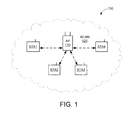
- FIG. 1 shows a block diagram of a WLAN system within which the example embodiments may be implemented.
- FIG. 2 shows a block diagram of a wireless station (STA) in accordance with some embodiments.
- FIG. 3 shows a block diagram of an example wireless signal transmission in the presence of multipath effects.
- FIG. 4A shows an example reception of a wireless signal at a receiving device.
- FIG. 4B shows an example reception of multipath wireless signals at a receiving device.
- FIG. 5 shows an example spectrum of a received wireless signal.
- FIG. 6 depicts an example graph of an Angle of Arrival (AoA) estimation function, in accordance with some embodiments.
- AoA Angle of Arrival
- FIG. 7A shows an illustrative flow chart depicting example operations for estimating an AoA of received signals in accordance with some embodiments.
- FIG. 7B shows an illustrative flow chart depicting example operations for determining the angle of arrival.
- FIG. 8A shows an illustrative flow chart depicting one example operations for setting weighting values of the operation of FIG. 7A .
- FIG. 8B shows an illustrative flow chart depicting another example operations for setting weighting values of the operation of FIG. 7A .
- Wi-Fi Wireless Local Area Network
- Wi-Fi® may include communications governed by the IEEE 802.11 family of standards, Bluetooth, HiperLAN (a set of wireless standards, comparable to the IEEE 802.11 standards, used primarily in Europe), and other technologies having relatively short radio propagation range.
- WLAN and “Wi-Fi” may be used interchangeably herein.
- the example embodiments are equally applicable to other WLAN systems including, for example, WLANs including a plurality of APs, peer-to-peer (or Independent Basic Service Set) systems, Wi-Fi Direct systems, and/or Hotspots.
- the example embodiments may be applied to the exchange of any data unit, packet, and/or frame between wireless devices.
- data packet may include any frame, packet, or data unit such as, for example, protocol data units (PDUs), MAC protocol data units (MPDUs), and physical layer convergence procedure protocol data units (PPDUs).
- PDUs protocol data units
- MPDUs MAC protocol data units
- PPDUs physical layer convergence procedure protocol data units
- A-MPDU may refer to aggregated MPDUs.
- circuit elements or software blocks may be shown as buses or as single signal lines.
- Each of the buses may alternatively be a single signal line, and each of the single signal lines may alternatively be buses, and a single line or bus might represent any one or more of a myriad of physical or logical mechanisms for communication between components.
- the example embodiments are not to be construed as limited to specific examples described herein but rather to include within their scopes all embodiments defined by the appended claims.
- one device may use AoA information for signals received from another device to determine its position.
- multipath effects may complicate and/or reduce the accuracy of the estimated AoA information.
- Multipath effects associated with signals transmitted from one device to another device may degrade the accuracy of the estimated AoA information.
- a signal transmitted from a first device to a second device may take multiple paths to reach the second device (e.g., due to reflections from physical obstacles between and/or near the two devices), thereby resulting in multiple “copies” or components of the signal arriving at the second device at different times and/or at different angles.
- the AoA of the signal component associated with the line of sight (LoS) path between the two devices typically provides the most accurate position information, and may therefore be of primary interest; other signal components associated with one or more non line of sight (NLoS) paths may degrade accuracy of the estimated AoA information.
- the example embodiments may improve the accuracy of estimated AoA information by identifying one or more received signal components associated with a first arrival path (FAP) to the receiving device, determining a phase of the identified FAP signal components, and then estimating the AoA information based on the determined phase of the identified FAP signal components.
- FAP first arrival path
- FIG. 1 is a block diagram of an example wireless network system 100 within which the example embodiments may be implemented.
- the system 100 is shown to include four wireless stations STA 1 -STA 4 , a wireless access point (AP) 110 , and a wireless local area network (WLAN) 120 .
- the WLAN 120 may be formed by a plurality of Wi-Fi access points (APs) that may operate according to the IEEE 802.11 family of standards (or according to other suitable wireless protocols).
- APs Wi-Fi access points
- the AP 110 is assigned a unique MAC address that is programmed therein by, for example, the manufacturer of the access point.
- each of STA 1 -STA 4 is also assigned a unique MAC address.
- the stations STA 1 -STA 4 may exchange signals directly with each other (e.g., without the presence of AP 110 ).
- the stations STA 1 -STA 4 may be any suitable Wi-Fi enabled wireless devices including, for example, cell phones, personal digital assistants (PDAs), tablet devices, laptop computers, or the like.
- the stations STA 1 -STA 4 may also be referred to as a user equipment (UE), a subscriber station, a mobile unit, a subscriber unit, a wireless unit, a remote unit, a mobile device, a wireless device, a wireless communications device, a remote device, a mobile subscriber station, an access terminal, a mobile terminal, a wireless terminal, a remote terminal, a handset, a user agent, a mobile client, a client, or some other suitable terminology.
- UE user equipment
- each of stations STA 1 -STA 4 may include a transceiver, one or more processing resources (e.g., processors and/or ASICs), one or more memory resources, and a power source (e.g., a battery).
- the memory resources may include a non-transitory computer-readable medium (e.g., one or more nonvolatile memory elements, such as EPROM, EEPROM, Flash memory, a hard drive, etc.) that stores instructions for performing operations described below with respect to FIGS. 7A-7B and 8A-8B .
- the AP 110 may be any suitable device that allows one or more wireless devices to connect to a network (e.g., a local area network (LAN), wide area network (WAN), metropolitan area network (MAN), and/or the Internet) via AP 110 using Wi-Fi, Bluetooth, or any other suitable wireless communication standards.
- a network e.g., a local area network (LAN), wide area network (WAN), metropolitan area network (MAN), and/or the Internet
- AP 110 may include a transceiver, a network interface, one or more processing resources, and one or more memory sources.
- the memory resources may include a non-transitory computer-readable medium (e.g., one or more nonvolatile memory elements, such as EPROM, EEPROM, Flash memory, a hard drive, etc.) that stores instructions for performing operations described operations described above or below with respect to FIGS. 7A-7B and 8A-8B .
- one or more functions of AP 110 may be performed by one of stations STA 1 -STA 4 .
- FIG. 2 shows a STA 200 that is one embodiment of at least one of the stations STA 1 -STA 4 of FIG. 1 .
- the STA 200 may include a transceiver 210 , at least one processor 220 , a memory 230 , and a number of antennas ANT 1 -ANTn.
- the transceiver 210 may be used to transmit signals to and receive signals from AP 110 and/or other STAs (see also FIG. 1 ), and may be used to scan the surrounding environment to detect and identify nearby access points (e.g., access points within range of STA 200 ) and/or nearby STAs.
- the transceiver 210 is coupled to the antennas ANT 1 -ANTn and to processor 220 .
- the number of antennas ANT 1 -ANTn when greater than one, may be used to provide multiple-input multiple-output (MIMO) functionality and antenna diversity.
- Antenna diversity may include polarization diversity, pattern diversity, and/or spatial diversity.
- processor 220 is shown as coupled between transceiver 210 and memory 230 .
- transceiver 210 , processor 220 , and/or memory 230 may be connected together using one or more buses (not shown for simplicity).
- Memory 230 may include a Wi-Fi database 231 that may store location data, configuration information, data rates, MAC addresses, timing information, modulation and coding schemes, and other suitable information of a number of access points and/or stations.
- Memory 230 may also include a non-transitory computer-readable storage medium (e.g., one or more nonvolatile memory elements, such as EPROM, EEPROM, Flash memory, a hard drive, and so on) that may store the following software modules (SW):
- SW software modules
- Processor 220 which is coupled to transceiver 210 and memory 230 , may be one or more suitable processors capable of executing scripts or instructions of one or more software programs stored in STA 200 (e.g., within memory 230 ).
- processor 220 may execute the frame formation and exchange software module 232 to facilitate the creation and/or exchange of various types of frames with one or more other wireless devices.
- Processor 220 may also execute the relative phase estimation software module 233 to facilitate the weighting of received signals and the estimation of relative phase information.
- Processor 220 may also execute the angle of arrival estimation software module 234 to facilitate the estimation of the FAP-AoA based, at least in part, on the relative phase information.
- FIG. 3 is an illustration 300 depicting a simplified example of multipath signal propagation between a first device (D 1 ) and a second device (D 2 ).
- the devices D 1 and D 2 may be any suitable wireless devices including, for example, the stations and/or APs shown in FIG. 1 .
- device D 1 transmits a signal 301 to device D 2 .
- device D 1 may be referred to as the transmitting device, and device D 2 may be referred to as the receiving device.
- the signal 301 may be any suitable signal (e.g., one or more packets or frames) from which AoA information may be estimated by device D 2 .
- the transmitted signal 301 includes a first signal component 301 A and a second signal component 301 B.
- the first signal component 301 A travels directly from device D 1 to device D 2 along a LoS path
- the second signal component 301 B travels indirectly from device D 1 to device D 2 along a NLoS path that reflects off barrier 303 (which may represent any physical obstruction between and/or near devices D 1 and D 2 ).
- the first signal component 301 A and the second signal component 301 B may arrive at device D 2 at different times and/or at different angles.
- AoA information of the first signal component 301 A may be used to derive an accurate position of device D 2 relative to device D 1 .
- AoA information of the second signal component 301 B may reduce the accuracy of position determination of device D 2 relative to device D 1 .
- the transmitted signal 301 may have any number of signal components that travel along any number of NLoS paths between devices D 1 and D 2 .
- the first signal component 301 A is depicted in FIG. 3 as being received by device D 2 without intervening reflections (e.g., such that the AoA of first signal component 301 A is substantially the same as the relative positional angle between devices D 1 and D 2 ), for many environments the first signal component 301 A may be reflected one or more times before reception by device D 2 .
- the devices D 1 and D 2 may include any number of antennas, for example, as depicted by STA 200 of FIG. 2 .
- each of its signal components 301 A and 301 B may be received by different antennas of device D 2 at different times due to physical spacing between the antennas.
- FIG. 4A is an illustration 400 depicting a signal 402 being received by a receiving device having two antennas ANT 1 and ANT 2 separated by a first distance d (receiving device not shown in FIG. 4A for simplicity).
- the signal 402 of FIG. 4A may represent any of the signal components 301 A- 301 B of the transmitted signal 301 shown in FIG. 3 .
- signal 402 is received at the first and second antennas ANT 1 and ANT 2 at an angle ⁇ relative to an axis line 403 extending between antennas ANT 1 and ANT 2 . Because the antennas ANT 1 and ANT 2 are separated by a distance d, the signal 402 as received by second antenna ANT 2 travels a distance equal to d sin ⁇ longer than the signal 402 as received by first antenna ANT 1 .
- the received signal y k (t) may be expressed as:
- y k ⁇ ( t ) h 1 ⁇ x ⁇ ( t - ⁇ 1 - kd c ⁇ sin ⁇ ⁇ ⁇ ) ⁇ h 1 ⁇ e - j2 ⁇ ⁇ ⁇ f c ⁇ kd c ⁇ sin ⁇ ⁇ ⁇ ⁇ x ⁇ ( t - ⁇ 1 ) ⁇ h 1 ⁇ e - j ⁇ ⁇ ⁇ k ⁇ ⁇ sin ⁇ ⁇ ⁇ ⁇ x ⁇ ( t - ⁇ 1 ) .
- c is the speed of light
- h 1 is the complex channel gain associated with the first path.
- FIG. 4B is an illustration 410 depicting a signal 412 having three signal components 412 ( 1 )- 412 ( 3 ) being received at three antennas ANT 1 -ANT 3 of a receiving device (receiving device not shown in FIG. 4B for simplicity).
- FIG. 4B is an illustration 410 depicting a signal 412 having three signal components 412 ( 1 )- 412 ( 3 ) being received at three antennas ANT 1 -ANT 3 of a receiving device (receiving device not shown in FIG. 4B for simplicity).
- the first signal component 412 ( 1 ) travels along a LoS path to the receiving device, and arrives at ANT 1 -ANT 3 at a first angle ⁇ 1 ;
- the second signal component 412 ( 2 ) travels along one NLoS path to the receiving device, and arrives at ANT 1 -ANT 3 at a second angle ⁇ 2 ,
- the third signal component 412 ( 3 ) travels along another NLoS path to the receiving device, and arrives at ANT 1 -ANT 3 at a third angle ⁇ 3 .
- the transmitted signal 412 may have any number of signal components that may travel along any number of NLoS paths and arrive at any number of corresponding angles.
- the receiving device is depicted as including three antennas ANT 1 -ANT 3 in the example FIG. 4B , the receiving device may include any number of antennas.
- the received signal y k (t) may be expressed (assuming a half-wavelength distance d between the antennas) as:
- y k ⁇ ( t ) ⁇ i ⁇ h i ⁇ x ⁇ ( t - ⁇ i - kd c ⁇ sin ⁇ ⁇ ⁇ i ) ⁇ ⁇ i ⁇ h i ⁇ e - j ⁇ ⁇ ⁇ k ⁇ ⁇ sin ⁇ ⁇ ⁇ i ⁇ x ⁇ ( t - ⁇ i ) .
- AoA information for all signal components may be estimated using known techniques including, for example, ESPRIT (Estimation of Signal Parameters via Rotational Invariance Techniques) and MUSIC (MUltiple Signal Classification).
- a receiving device having a number N of antennas may accurately estimate AoA information for up to a number M of different signal paths using conventional techniques such as ESPRIT and MUSIC, where N ⁇ M+1,
- the number of antennas provided on such wireless devices may be less than the minimum number needed for the above AoA estimation techniques to provide accurate AoA information for multipath signals.
- decreasing the number of antennas provided on a receiving device may reduce the ability of the receiving device to estimate AoA information for signals having multiple paths and angles of arrival.
- An AoA estimation technique is disclosed herein that may overcome the limitations of conventional AoA estimation techniques when a receiving device has a limited number of antennas to receive a signal having a plurality of signal components traveling along a plurality of signal paths. More specifically, the AoA estimate technique disclosed herein may determine an accurate AoA estimate for the signal component that is first to arrive at the receiving device. This signal component may correspond to the first arrival path (FAP) of the received signal, and thus the AoA estimate technique disclosed herein may be referred to as the “FAP-AoA estimation” technique.
- the FAP-AoA estimation technique disclosed herein may be based, at least in part, on the signal components received along NLoS paths arriving at the receiving device later than the signal component received along the first arrival path.
- FIG. 5 shows a spectrum 500 of an example signal 501 received from a transmitting device (not shown in FIG. 5 ) in the presence of multipath effects.
- the received signal 501 may be a superposition of multiple sinc pulses, each associated with a corresponding peak or “tap” at a corresponding time value.
- the spectrum 500 includes a main lobe 502 occurring between approximately times t 4 and t 6 , and includes a plurality of secondary lobes 503 A and 503 B on either side of the main lobe 502 .
- the main lobe 502 includes a first peak 502 A and a second peak 502 B of different magnitudes (e.g., caused by multipath effects).
- the first peak 502 A which has a greater magnitude than the second peak 502 B, represents the signal components traveling along the first arrival path (FAP) to the receiving device (receiving device not shown in FIG. 5 ).
- the first peak 502 A and one or more of the secondary lobes 503 A on the left side of the main lobe 502 may be less corrupted than the second peak 502 B and the secondary lobes 503 B on the right side of the main lobe 502 .
- the first peak and the one or more secondary lobes 503 A on the left side of the main lobe 502 may be embedded with the phase information of the FAP signal components, and therefore the first peak 502 A and zero or more of the secondary lobes 503 A may be used to estimate the AoA information of the received signal 501 .
- the taps associated with the first peak 502 A and the secondary lobes 503 A on the left side of the main lobe 502 may be assigned greater weighting values than the taps associated with the second peak 502 B and the secondary lobes 503 B on the right side of the main lobe 502 .
- This may provide a more accurate estimate of the AoA information of the received signal 501 , for example, by placing a greater emphasis on FAP signal components than on other (e.g., non-FAP) signal components.
- the signals y k (t) received at each of a plurality of antennas of the receiving device may be multiplied with a set of weighting values w(t) to generate a weighted receive signal.
- the weighting values w(t) may be selected to extract the portion of the spectrum 500 containing the FAP information (e.g., the portion of the spectrum 500 on the left side of the main lobe 502 ).
- the weighting values w(t) may be set to unity for the first tap corresponding to a spectral magnitude above a threshold, the weighting values w(t) may be set to unity for one or more adjacent taps (to the left of the first tap), and the weighting values w(t) may be set to zero for all other taps.
- the threshold is set to an example magnitude value of 0.05
- the first tap T 0 corresponds to the first peak 502 A (which is the only tap having a magnitude greater than the threshold); additional taps T 1 and T 2 are depicted in FIG. 5 as candidate taps for which the corresponding weighting values may be set to unity.
- the weighting values w(t) may be set to unity for the tap having the largest spectral magnitude, the weighting values w(t) may be set to unity for at least one adjacent tap (to the left of the first tap), and the weighting values w(t) may be set to zero for all other taps. Still further, the weighting values w(t) may be set to unity for all taps having a spectral magnitude above the threshold, and the weighting values w(t) may be set to zero for all other taps.
- the weighting values w(t) may be a function of the channel response (e.g., an impulse time response) observed by the receiving device.
- the phase information may be determined from the signal ⁇ tilde over (y) ⁇ k (t) using a parametric algorithm.
- known AoA estimation techniques such as MUSIC or ESPRIT may be used as the parametric algorithm.
- the phase information may be extracted from the weighted signal ⁇ tilde over (y) ⁇ k (t) using the best ML estimate, as described above.
- the AoA of the FAP signal components may be estimated based on the determined phase information of the weighted signal ⁇ tilde over (y) ⁇ k (t).
- ⁇ the weighted signal ⁇ tilde over (y) ⁇ k (t).
- multiple phase estimates may be derived from the signal ⁇ tilde over (y) ⁇ k (t) using the parametric algorithm and then a higher-order estimation function may be used to select the correct phase from the derived multiple phase estimates.
- This higher-order estimation function may be used to derive a relationship between ⁇ and ⁇ .
- ⁇ ( ⁇ , ⁇ )
- ⁇ ( ⁇ , ⁇ )
- the FAP angle ⁇ may be estimated by first estimating all local minima of the function ⁇ ( ⁇ , ⁇ ). Note that ⁇ i , ⁇ i , and ⁇ i are parameters determined algorithmically by fitting the minima of ⁇ ( ⁇ , ⁇ ) to the FAP angle ⁇ .
- the relative phase ⁇ may range from 0 to 360 degrees (or from 0 to 2 ⁇ radians).
- FIG. 6 depicts an example plot 600 of the function ⁇ ( ⁇ , ⁇ ), in accordance with some embodiments.
- the example plot 600 includes minima M 1 , M 2 , and M 3 at approximately 150 degrees, at approximately 200 degrees, and at approximately 350 degrees, respectively. Because a rough approximation of the FAP angle is known, any suitable tracking function may be used to select the local minimum closest to the approximation.
- FIG. 7A is a flow chart depicting an example operation 700 for determining the AoA of a wireless signal received by a receiving device.
- the receiving device may receive a wireless signal including a plurality of signal components ( 702 ). As described above, the plurality of signal components may arrive at the receiving device along a number of different arrival paths. Then, the receiving device may generate a plurality of weighted signal components by multiplying the plurality of signal components of the received wireless signal with a set of weighting values ( 704 ). The plurality of weighted signal components may be combined to construct a weighted signal.
- the receiving device may identify one or more of the weighted signal components associated with a first arrival path to the device ( 706 ), and then may determine phase information of the one or more identified weighted signal components ( 708 ). The receiving device may determine the angle of arrival of the received wireless signal based, at least in part, on the determined phase information ( 710 ).
- FIG. 7B is a flow chart depicting an example operation 750 for determining the angle of arrival by a receiving device.
- the receiving device may select a function indicating a relationship between angle of arrival information and the phase information ( 752 ).
- the receiving device may then determine one or more local minima of the selected function ( 754 ).
- the receiving device may then select one of the determined one or more local minima that is closest to a coarse approximation of the angle of arrival ( 756 ).
- FIG. 8A is a flow chart depicting one example operation 800 for setting the weighting values.
- the receiving device may represent the received wireless signal as a spectral plot including a plurality of taps each at a corresponding time value ( 802 ).
- the receiving device may identify, in the spectral plot, one or more taps having a magnitude above a threshold value ( 804 ).
- the receiving device may set the weighting values for the one or more identified taps to unity ( 806 ).
- the receiving device may set the weighting values for all other taps to zero ( 808 ).
- FIG. 8B is a flow chart depicting another example operation 850 for setting the weighting values.
- the receiving device may represent the received wireless signal as a spectral plot including a plurality of taps each at a corresponding time value ( 852 ).
- the receiving device may identify, in the spectral plot, the tap having the largest magnitude (or having a magnitude above a threshold value ( 854 ).
- the receiving device may set the weighting values for the identified tap and at least one adjacent tap to unity ( 856 ).
- the receiving device may set the weighting values for all other taps to zero ( 858 ).
Abstract
Description
-
- a frame formation and
exchange software module 232 to facilitate the creation and exchange of frames (e.g., data frames, ACK frames, request frames, response frames, beacon frames, management frames, association frames, control frames, fine timing measurement (FTM) frames, and so on), for example, as described with respect toFIGS. 7A-7B and 8A-8B ; - a relative phase
estimation software module 233 to apply weighting values to one or more components of received signals to estimate the relative phase information of the received signals, for example, as described with respect toFIGS. 7A-7B and 8A-8B ; and - an angle of arrival
estimation software module 234 to estimate the AoA of one or more received signal components associated with the first arrival path (FAP) based, at least in part, on the estimated relative phase information, for example, as described with respect toFIGS. 7A-7B and 8A-8B . Each software module includes instructions that, when executed byprocessor 220, may causeSTA 200 to perform the corresponding functions. The non-transitory computer-readable medium ofmemory 230 thus includes instructions for performing all or a portion of the operations of the method ofFIGS. 7A-7B and 8A-8B .
- a frame formation and
where c is the speed of light, and h1 is the complex channel gain associated with the first path. Then, the maximum likelihood (ML) estimate of the angle of arrival for a two antenna receiving device (e.g., as depicted in
angle(Σt y k*(t)y k-1(t))=π sin θ.
{tilde over (y)} k(t)=w(t)y k(t)
w(t)=e −η
w(t)=e −η
where and η1 and η2 may be parameters selected, for example, by a user of the receiving device. For still other embodiments, the weighting values w(t) may be a function of the channel response (e.g., an impulse time response) observed by the receiving device.
φ=Σiαi sin(θ+βi)+γi.
ƒ(φ,θ)=|e jφ −e j(α
Claims (26)
Priority Applications (2)
| Application Number | Priority Date | Filing Date | Title |
|---|---|---|---|
| US14/644,613 US9445237B1 (en) | 2015-03-11 | 2015-03-11 | First arrival path based multipath mitigation for angle of arrival estimation |
| PCT/US2016/017619 WO2016144477A1 (en) | 2015-03-11 | 2016-02-11 | First arrival path based multipath mitigation for angle of arrival estimation |
Applications Claiming Priority (1)
| Application Number | Priority Date | Filing Date | Title |
|---|---|---|---|
| US14/644,613 US9445237B1 (en) | 2015-03-11 | 2015-03-11 | First arrival path based multipath mitigation for angle of arrival estimation |
Publications (2)
| Publication Number | Publication Date |
|---|---|
| US9445237B1 true US9445237B1 (en) | 2016-09-13 |
| US20160269859A1 US20160269859A1 (en) | 2016-09-15 |
Family
ID=55442881
Family Applications (1)
| Application Number | Title | Priority Date | Filing Date |
|---|---|---|---|
| US14/644,613 Active US9445237B1 (en) | 2015-03-11 | 2015-03-11 | First arrival path based multipath mitigation for angle of arrival estimation |
Country Status (2)
| Country | Link |
|---|---|
| US (1) | US9445237B1 (en) |
| WO (1) | WO2016144477A1 (en) |
Cited By (6)
| Publication number | Priority date | Publication date | Assignee | Title |
|---|---|---|---|---|
| JP2018017695A (en) * | 2016-07-29 | 2018-02-01 | 国立大学法人東京工業大学 | Originating source estimating method and originating source estimating apparatus using the same |
| US20190313363A1 (en) * | 2016-12-26 | 2019-10-10 | Huawei Technologies Co., Ltd. | Method for identifying line of sight path and wireless device |
| US20200132798A1 (en) * | 2018-10-31 | 2020-04-30 | Kabushiki Kaisha Toshiba | Electronic apparatus, angle estimation system, and signal processing method |
| US10917870B2 (en) | 2018-08-23 | 2021-02-09 | Huawei Technologies Co., Ltd. | Angle of arrival estimation method and device |
| CN112673269A (en) * | 2018-09-28 | 2021-04-16 | 苹果公司 | Techniques for improving New Radio (NR) positioning performance |
| CN114553332A (en) * | 2020-11-25 | 2022-05-27 | 联发科技股份有限公司 | Electronic equipment, wireless communication chip and channel state information measuring method |
Families Citing this family (3)
| Publication number | Priority date | Publication date | Assignee | Title |
|---|---|---|---|---|
| CN108243475B (en) * | 2016-12-26 | 2021-06-22 | 华为技术有限公司 | Positioning method based on wireless network and wireless equipment |
| EP3351957B8 (en) | 2017-01-20 | 2021-12-29 | Rohde & Schwarz GmbH & Co. KG | Method and device for direction finding with direction evaluation |
| EP4288791A2 (en) * | 2021-02-02 | 2023-12-13 | Qualcomm Incorporated | Reference signal received power measurement based on peak of earliest path |
Citations (14)
| Publication number | Priority date | Publication date | Assignee | Title |
|---|---|---|---|---|
| US3553697A (en) | 1968-04-30 | 1971-01-05 | Us Navy | Channel combiner system for sequentially received phase signals |
| US4150378A (en) | 1978-03-13 | 1979-04-17 | International Standard Electric Corporation | Height finding radar |
| WO1998018018A1 (en) | 1996-10-24 | 1998-04-30 | Northern Telecom Limited | Determining direction of a mobile terminal in a cellular communication system |
| US6459903B1 (en) | 1999-03-11 | 2002-10-01 | Samsung Electronics Co., Ltd. | Method and system for locating mobile station in mobile telecommunication system |
| US20030012265A1 (en) | 2001-07-04 | 2003-01-16 | Tsui-Tsai Lin | Apparatus and method for estimating angle-of-arrival |
| US20030069047A1 (en) * | 2001-10-10 | 2003-04-10 | Minako Kitahara | Adaptive array antenna directivity control system |
| US20040048593A1 (en) | 2000-12-21 | 2004-03-11 | Hiroyasu Sano | Adaptive antenna receiver |
| US6892054B2 (en) * | 2000-12-29 | 2005-05-10 | Wherenet Corp | Interference suppression for wireless local area network and location system |
| US20060072524A1 (en) | 2004-10-01 | 2006-04-06 | Eldad Perahia | Multiple antenna processing on transmit for wireless local area networks |
| US7409227B2 (en) | 2003-03-11 | 2008-08-05 | Fujitsu Limited | Radio apparatus |
| US20080219099A1 (en) * | 2007-03-08 | 2008-09-11 | Novick Arnold W | Determining angles of arrival using multipaths |
| US8548097B1 (en) | 2012-06-20 | 2013-10-01 | MagnaCom Ltd. | Coarse phase estimation for highly-spectrally-efficient communications |
| US8619908B2 (en) * | 2009-12-02 | 2013-12-31 | Harris Corporation | Wireless ranging system and related methods |
| US8797213B2 (en) | 2009-09-30 | 2014-08-05 | Broadcom Corporation | Methods and systems for estimating angle of arrival |
-
2015
- 2015-03-11 US US14/644,613 patent/US9445237B1/en active Active
-
2016
- 2016-02-11 WO PCT/US2016/017619 patent/WO2016144477A1/en active Application Filing
Patent Citations (14)
| Publication number | Priority date | Publication date | Assignee | Title |
|---|---|---|---|---|
| US3553697A (en) | 1968-04-30 | 1971-01-05 | Us Navy | Channel combiner system for sequentially received phase signals |
| US4150378A (en) | 1978-03-13 | 1979-04-17 | International Standard Electric Corporation | Height finding radar |
| WO1998018018A1 (en) | 1996-10-24 | 1998-04-30 | Northern Telecom Limited | Determining direction of a mobile terminal in a cellular communication system |
| US6459903B1 (en) | 1999-03-11 | 2002-10-01 | Samsung Electronics Co., Ltd. | Method and system for locating mobile station in mobile telecommunication system |
| US20040048593A1 (en) | 2000-12-21 | 2004-03-11 | Hiroyasu Sano | Adaptive antenna receiver |
| US6892054B2 (en) * | 2000-12-29 | 2005-05-10 | Wherenet Corp | Interference suppression for wireless local area network and location system |
| US20030012265A1 (en) | 2001-07-04 | 2003-01-16 | Tsui-Tsai Lin | Apparatus and method for estimating angle-of-arrival |
| US20030069047A1 (en) * | 2001-10-10 | 2003-04-10 | Minako Kitahara | Adaptive array antenna directivity control system |
| US7409227B2 (en) | 2003-03-11 | 2008-08-05 | Fujitsu Limited | Radio apparatus |
| US20060072524A1 (en) | 2004-10-01 | 2006-04-06 | Eldad Perahia | Multiple antenna processing on transmit for wireless local area networks |
| US20080219099A1 (en) * | 2007-03-08 | 2008-09-11 | Novick Arnold W | Determining angles of arrival using multipaths |
| US8797213B2 (en) | 2009-09-30 | 2014-08-05 | Broadcom Corporation | Methods and systems for estimating angle of arrival |
| US8619908B2 (en) * | 2009-12-02 | 2013-12-31 | Harris Corporation | Wireless ranging system and related methods |
| US8548097B1 (en) | 2012-06-20 | 2013-10-01 | MagnaCom Ltd. | Coarse phase estimation for highly-spectrally-efficient communications |
Non-Patent Citations (2)
| Title |
|---|
| Inserra D., et al., "A Frequency-Domain LOS Angle-of-Arrival Estimation Approach in Multipath Channels," IEEE Transactions on Vehicular Technology, 2013, vol. 62 (6), pp. 2812-2818. |
| International Search Report and Written Opinion-PCT/US2016/017619-ISA/EPO-May 11, 2016. |
Cited By (8)
| Publication number | Priority date | Publication date | Assignee | Title |
|---|---|---|---|---|
| JP2018017695A (en) * | 2016-07-29 | 2018-02-01 | 国立大学法人東京工業大学 | Originating source estimating method and originating source estimating apparatus using the same |
| US20190313363A1 (en) * | 2016-12-26 | 2019-10-10 | Huawei Technologies Co., Ltd. | Method for identifying line of sight path and wireless device |
| JP2020514712A (en) * | 2016-12-26 | 2020-05-21 | 華為技術有限公司Huawei Technologies Co.,Ltd. | Method and wireless device for line-of-sight path identification |
| US10917870B2 (en) | 2018-08-23 | 2021-02-09 | Huawei Technologies Co., Ltd. | Angle of arrival estimation method and device |
| CN112673269A (en) * | 2018-09-28 | 2021-04-16 | 苹果公司 | Techniques for improving New Radio (NR) positioning performance |
| US20200132798A1 (en) * | 2018-10-31 | 2020-04-30 | Kabushiki Kaisha Toshiba | Electronic apparatus, angle estimation system, and signal processing method |
| US11585885B2 (en) * | 2018-10-31 | 2023-02-21 | Kabushiki Kaisha Toshiba | Electronic apparatus, angle estimation system, and signal processing method |
| CN114553332A (en) * | 2020-11-25 | 2022-05-27 | 联发科技股份有限公司 | Electronic equipment, wireless communication chip and channel state information measuring method |
Also Published As
| Publication number | Publication date |
|---|---|
| WO2016144477A1 (en) | 2016-09-15 |
| US20160269859A1 (en) | 2016-09-15 |
Similar Documents
| Publication | Publication Date | Title |
|---|---|---|
| US9445237B1 (en) | First arrival path based multipath mitigation for angle of arrival estimation | |
| Menta et al. | On the performance of AoA–based localization in 5G ultra–dense networks | |
| US10064154B2 (en) | System and method for channel information exchange for time of flight range determination | |
| CN109565777B (en) | Communication node for positioning in a wireless communication network and method therein | |
| US9730179B2 (en) | Passive locationing over multiple channels | |
| US9819516B2 (en) | Channel estimation in wireless communications | |
| US20160234704A1 (en) | Ftm protocol with angle of arrival and angle of departure | |
| US11943022B2 (en) | Techniques for elevated device communication | |
| US20220271818A1 (en) | Non-Line-of-Sight Path Detection for User Equipment Positioning in Wireless Networks | |
| US9014172B2 (en) | High resolution wireless indoor positioning system for legacy standards-based narrowband mobile radios | |
| Solanki et al. | On the performance of IRS-aided UAV networks with NOMA | |
| US10674331B1 (en) | Indoor location estimation for wireless device | |
| US20230288517A1 (en) | Apparatus and Methods for Determining Line of Sight (LOS) from Intensity Measurements | |
| US9161330B2 (en) | Method of enabling single chain ranging operations | |
| US11019457B2 (en) | Method for reducing wireless positioning error in multi-node system and terminal therefor | |
| Li et al. | Beam scanning for integrated sensing and communication in IRS-aided mmwave systems | |
| US8825077B2 (en) | Method and system for femtocell positioning | |
| US20240015693A1 (en) | User equipment (ue) positioning | |
| US11864150B2 (en) | Uplink coordinated multipoint positioning | |
| KR102386229B1 (en) | Method and appatus of interference measurement in wireless communication system | |
| US20230184877A1 (en) | Positioning a Terminal Device | |
| US11510172B1 (en) | Device detection and locationing within a wireless network | |
| US20180310317A1 (en) | Apparatuses, methods, computer programs, and computer program products for interference avoidance | |
| EP4191270A1 (en) | Device positioning | |
| WO2024065820A1 (en) | Improvement of accuracy of angle based positioning |
Legal Events
| Date | Code | Title | Description |
|---|---|---|---|
| AS | Assignment |
Owner name: QUALCOMM INCORPORATED, CALIFORNIA Free format text: ASSIGNMENT OF ASSIGNORS INTEREST;ASSIGNORS:NALLAMPATTI EKAMBARAM, VENKATESAN;NARASIMHA SWAMY, VASUKI;JOSE, JUBIN;AND OTHERS;SIGNING DATES FROM 20150311 TO 20150413;REEL/FRAME:035402/0610 |
|
| FEPP | Fee payment procedure |
Free format text: PAYOR NUMBER ASSIGNED (ORIGINAL EVENT CODE: ASPN); ENTITY STATUS OF PATENT OWNER: LARGE ENTITY |
|
| STCF | Information on status: patent grant |
Free format text: PATENTED CASE |
|
| MAFP | Maintenance fee payment |
Free format text: PAYMENT OF MAINTENANCE FEE, 4TH YEAR, LARGE ENTITY (ORIGINAL EVENT CODE: M1551); ENTITY STATUS OF PATENT OWNER: LARGE ENTITY Year of fee payment: 4 |
|
| MAFP | Maintenance fee payment |
Free format text: PAYMENT OF MAINTENANCE FEE, 8TH YEAR, LARGE ENTITY (ORIGINAL EVENT CODE: M1552); ENTITY STATUS OF PATENT OWNER: LARGE ENTITY Year of fee payment: 8 |