US9446877B1 - System and apparatus for applying labels to cable or conduit - Google Patents
System and apparatus for applying labels to cable or conduit Download PDFInfo
- Publication number
- US9446877B1 US9446877B1 US14/453,273 US201414453273A US9446877B1 US 9446877 B1 US9446877 B1 US 9446877B1 US 201414453273 A US201414453273 A US 201414453273A US 9446877 B1 US9446877 B1 US 9446877B1
- Authority
- US
- United States
- Prior art keywords
- conduit
- cable
- label
- guide shoe
- guide
- Prior art date
- Legal status (The legal status is an assumption and is not a legal conclusion. Google has not performed a legal analysis and makes no representation as to the accuracy of the status listed.)
- Active, expires
Links
- 239000004020 conductor Substances 0.000 claims description 24
- 239000003086 colorant Substances 0.000 claims description 7
- 238000003825 pressing Methods 0.000 claims description 6
- 238000000034 method Methods 0.000 description 29
- 238000010586 diagram Methods 0.000 description 24
- 238000002372 labelling Methods 0.000 description 20
- 230000008569 process Effects 0.000 description 20
- 229910052782 aluminium Inorganic materials 0.000 description 8
- XAGFODPZIPBFFR-UHFFFAOYSA-N aluminium Chemical compound [Al] XAGFODPZIPBFFR-UHFFFAOYSA-N 0.000 description 8
- 229910052751 metal Inorganic materials 0.000 description 8
- 239000002184 metal Substances 0.000 description 8
- 229910000831 Steel Inorganic materials 0.000 description 7
- 239000010959 steel Substances 0.000 description 7
- 230000007704 transition Effects 0.000 description 6
- 239000000853 adhesive Substances 0.000 description 3
- 230000001070 adhesive effect Effects 0.000 description 3
- 230000036541 health Effects 0.000 description 3
- 230000004048 modification Effects 0.000 description 3
- 238000012986 modification Methods 0.000 description 3
- RYGMFSIKBFXOCR-UHFFFAOYSA-N Copper Chemical compound [Cu] RYGMFSIKBFXOCR-UHFFFAOYSA-N 0.000 description 2
- 230000008901 benefit Effects 0.000 description 2
- 229910052802 copper Inorganic materials 0.000 description 2
- 239000010949 copper Substances 0.000 description 2
- 238000009499 grossing Methods 0.000 description 2
- 239000007788 liquid Substances 0.000 description 2
- 230000007935 neutral effect Effects 0.000 description 2
- 239000000843 powder Substances 0.000 description 2
- 230000004075 alteration Effects 0.000 description 1
- 230000001680 brushing effect Effects 0.000 description 1
- PCHJSUWPFVWCPO-UHFFFAOYSA-N gold Chemical compound [Au] PCHJSUWPFVWCPO-UHFFFAOYSA-N 0.000 description 1
- 239000010931 gold Substances 0.000 description 1
- 229910052737 gold Inorganic materials 0.000 description 1
- 239000012212 insulator Substances 0.000 description 1
- 238000004519 manufacturing process Methods 0.000 description 1
- 239000000463 material Substances 0.000 description 1
- 238000005507 spraying Methods 0.000 description 1
Images


Classifications
-
- B—PERFORMING OPERATIONS; TRANSPORTING
- B65—CONVEYING; PACKING; STORING; HANDLING THIN OR FILAMENTARY MATERIAL
- B65C—LABELLING OR TAGGING MACHINES, APPARATUS, OR PROCESSES
- B65C3/00—Labelling other than flat surfaces
- B65C3/02—Affixing labels to elongated objects, e.g. wires, cables, bars, tubes
-
- B—PERFORMING OPERATIONS; TRANSPORTING
- B65—CONVEYING; PACKING; STORING; HANDLING THIN OR FILAMENTARY MATERIAL
- B65C—LABELLING OR TAGGING MACHINES, APPARATUS, OR PROCESSES
- B65C9/00—Details of labelling machines or apparatus
- B65C9/08—Label feeding
-
- B—PERFORMING OPERATIONS; TRANSPORTING
- B65—CONVEYING; PACKING; STORING; HANDLING THIN OR FILAMENTARY MATERIAL
- B65C—LABELLING OR TAGGING MACHINES, APPARATUS, OR PROCESSES
- B65C9/00—Details of labelling machines or apparatus
- B65C9/26—Devices for applying labels
-
- B—PERFORMING OPERATIONS; TRANSPORTING
- B65—CONVEYING; PACKING; STORING; HANDLING THIN OR FILAMENTARY MATERIAL
- B65C—LABELLING OR TAGGING MACHINES, APPARATUS, OR PROCESSES
- B65C9/00—Details of labelling machines or apparatus
- B65C9/26—Devices for applying labels
- B65C9/36—Wipers; Pressers
-
- B—PERFORMING OPERATIONS; TRANSPORTING
- B65—CONVEYING; PACKING; STORING; HANDLING THIN OR FILAMENTARY MATERIAL
- B65C—LABELLING OR TAGGING MACHINES, APPARATUS, OR PROCESSES
- B65C9/00—Details of labelling machines or apparatus
- B65C9/40—Controls; Safety devices
- B65C9/42—Label feed control
-
- G—PHYSICS
- G09—EDUCATION; CRYPTOGRAPHY; DISPLAY; ADVERTISING; SEALS
- G09F—DISPLAYING; ADVERTISING; SIGNS; LABELS OR NAME-PLATES; SEALS
- G09F3/00—Labels, tag tickets, or similar identification or indication means; Seals; Postage or like stamps
- G09F3/02—Forms or constructions
- G09F3/0295—Labels or tickets for tubes, pipes and the like
-
- H—ELECTRICITY
- H01—ELECTRIC ELEMENTS
- H01L—SEMICONDUCTOR DEVICES NOT COVERED BY CLASS H10
- H01L21/00—Processes or apparatus adapted for the manufacture or treatment of semiconductor or solid state devices or of parts thereof
- H01L21/67—Apparatus specially adapted for handling semiconductor or electric solid state devices during manufacture or treatment thereof; Apparatus specially adapted for handling wafers during manufacture or treatment of semiconductor or electric solid state devices or components ; Apparatus not specifically provided for elsewhere
- H01L21/67005—Apparatus not specifically provided for elsewhere
- H01L21/67011—Apparatus for manufacture or treatment
- H01L21/67144—Apparatus for mounting on conductive members, e.g. leadframes or conductors on insulating substrates
-
- Y—GENERAL TAGGING OF NEW TECHNOLOGICAL DEVELOPMENTS; GENERAL TAGGING OF CROSS-SECTIONAL TECHNOLOGIES SPANNING OVER SEVERAL SECTIONS OF THE IPC; TECHNICAL SUBJECTS COVERED BY FORMER USPC CROSS-REFERENCE ART COLLECTIONS [XRACs] AND DIGESTS
- Y10—TECHNICAL SUBJECTS COVERED BY FORMER USPC
- Y10T—TECHNICAL SUBJECTS COVERED BY FORMER US CLASSIFICATION
- Y10T156/00—Adhesive bonding and miscellaneous chemical manufacture
- Y10T156/10—Methods of surface bonding and/or assembly therefor
- Y10T156/1002—Methods of surface bonding and/or assembly therefor with permanent bending or reshaping or surface deformation of self sustaining lamina
- Y10T156/1028—Methods of surface bonding and/or assembly therefor with permanent bending or reshaping or surface deformation of self sustaining lamina by bending, drawing or stretch forming sheet to assume shape of configured lamina while in contact therewith
- Y10T156/1033—Flexible sheet to cylinder lamina
-
- Y—GENERAL TAGGING OF NEW TECHNOLOGICAL DEVELOPMENTS; GENERAL TAGGING OF CROSS-SECTIONAL TECHNOLOGIES SPANNING OVER SEVERAL SECTIONS OF THE IPC; TECHNICAL SUBJECTS COVERED BY FORMER USPC CROSS-REFERENCE ART COLLECTIONS [XRACs] AND DIGESTS
- Y10—TECHNICAL SUBJECTS COVERED BY FORMER USPC
- Y10T—TECHNICAL SUBJECTS COVERED BY FORMER US CLASSIFICATION
- Y10T156/00—Adhesive bonding and miscellaneous chemical manufacture
- Y10T156/17—Surface bonding means and/or assemblymeans with work feeding or handling means
- Y10T156/1702—For plural parts or plural areas of single part
- Y10T156/1744—Means bringing discrete articles into assembled relationship
Definitions
- the present invention relates in general to applying labels to a cable or conduit, and more particularly, to a system and apparatus for applying labels to a moving cable or conduit.
- a cable or conduit generally consists of one or more internal conductors and a sheath that envelopes the one or more internal conductors. Labels are then applied to the sheath of the cable or conduit to identify characteristics of the cable or conduit, for example, the type and size of the cable or conduit.
- various methods are used to apply specific colors to cable or conduit and/or conduit.
- One method is to apply an ink directly to an outer sheath of the cable or conduit by spraying, wiping, dripping, brushing, etc.
- colors applied by this method may not be easily removed and the method in which the ink is applied may not be easily managed as liquid or powder is used. Therefore, a need exists for an apparatus and a method for applying colored labels to cable or conduit and/or conduit without the disadvantages of the existing methods.
- the present invention provides a system and apparatus for applying labels to a cable or conduit.
- a system for applying labels to cable or conduit comprising: at least one label, a label applicator for applying the label to the cable or conduit, the label applicator comprising at least one guide roller for guiding a moving cable or conduit, at least one tamping device comprising at least one tamping pad for applying at least one label onto the moving cable or conduit; and a guide shoe assembly, the guide shoe assembly comprising: a guide shoe mounted at a level that is horizontal and substantially even with the moving cable or conduit for pressing the label directly against at least a portion of the moving cable or conduit, wherein the guide shoe comprises a rounding member, a plurality of springs for providing flexibility to the rounding member when the moving cable or conduit passes the at least one guide shoe, a support mount for supporting the at least one guide shoe, a plurality of pivots disposed between the rounding member and the rounding member support for adjusting the set of springs, and a fitted member for providing an anchor for the at least one guide shoe to connect with the support mount.
- a system for applying labels to cable or conduit comprising: at least one label, a label applicator for applying the label to the cable or conduit, the label applicator comprising: at least one guide roller for guiding a moving cable or conduit, at least one tamping device comprising: at least one tamping pad for applying at least one label onto the moving cable or conduit, wherein the at least one tamping device comprises a set of hydraulics for driving the at least one tamping pad downward onto the moving cable or conduit, and a guide shoe assembly, the guide shoe assembly comprising: a plurality of guide shoes individually mounted at a level that is horizontal and substantially even with the moving cable or conduit for pressing the at least one label against a portion of the moving cable or conduit, wherein the plurality of guide shoes comprises: a rounding member, a rounding member support for supporting the rounding member, a plurality of springs for providing flexibility to the rounding member when the moving cable or conduit passes the at least one guide shoe, a support mount for supporting the at least one guide shoe
- FIG. 1 is a diagram of an exemplary cable or conduit in accordance with one embodiment of the present disclosure
- FIG. 2 is a diagram of exemplary labels for application to a cable or conduit in accordance with one embodiment of the present disclosure
- FIG. 3 is a diagram of an exemplary labeling unit for applying labels in accordance with one embodiment of the present disclosure
- FIG. 4A is a diagram of an exemplary tamping pad in accordance with one embodiment of the present disclosure.
- FIG. 4B is a diagram of an exemplary moving cable or conduit after initial affixing of labels by the tamping device in accordance with one embodiment of the present disclosure
- FIG. 5 is a diagram of a top view of a guide shoe assembly is depicted in accordance with one embodiment of the present disclosure
- FIGS. 6A to 6C are diagrams illustrating side views of exemplary guide shoes in accordance with one embodiment of the present disclosure.
- FIG. 7A is a diagram illustrating a side view of an exemplary guide shoe in accordance with one embodiment of the present disclosure.
- FIG. 7B is a diagram illustrating a top view of a guide shoe in accordance with one embodiment of the present disclosure.
- FIG. 8A is a diagram illustrating a side view of a guide shoe in accordance with an alternative embodiment of the present disclosure.
- FIG. 8B is a diagram illustrating a side view of a guide shoe in accordance with an alternative embodiment of the present disclosure.
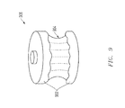
- FIG. 9 is a diagram illustrating an exemplary guide roller in accordance with one embodiment of the present disclosure.
- FIG. 10 is a flowchart of a process for applying labels to a cable or conduit in accordance with one embodiment of the present disclosure.
- FIG. 11 is a flowchart of a process for affixing labels to a cable or conduit with a tamping device in accordance with one embodiment of the present disclosure.
- FIG. 12 is a flowchart of a process for pressing the label against at least one side of the cable or conduit using a set of guide shoes.
- cable or conduit 100 consists of one or more internal conductors 102 and 104 .
- Internal conductors 102 and 104 are preferably insulated by an insulator and jacketed and are enveloped by a sheath 106 .
- Sheath 106 may be made of a conducting material such as aluminum or steel.
- Cable or conduit 100 may also be of different types including, but not limited to, corrugated, interlocking, waterproof/liquid-tight, or flexible metal conduit.
- labels 200 A and 200 B may be made with or without adhesive, which enables the removal of the label easier.
- Labels 200 A and 200 B may be conductive or non-conductive, and polymeric or metallic in nature.
- labels 200 A and 200 B are of a polymeric heat-induced shrink-wrap type such that when labels 200 A and 200 B are heated, the labels shrink and wrap tightly around the sheath 106 of the cable or conduit 100 in a manner to be discussed further below. Labels other than heat-induced shrink-wrap type may also be used without departing the spirit and scope of the present disclosure.
- Label 200 A is color-coded edge-to-edge according to a color scheme.
- label 200 A is color-coded to indicate the internal conductor wire size according to the American Wire Gauge (AWG) standard.
- AWG American Wire Gauge
- label 200 A is white in color, which indicates that the size of the internal conductors is 14AWG.
- the color scheme for the internal conductors wire size also includes a yellow color to indicate wire size of 12AWG; an orange color to indicate wire size of 10AWG; a black color to indicate wire size of 8AWG; a purple color to indicate wire size of 6AWG; a brown color to indicate wire size of 4AWG; a tan color to indicate wire size of 3AWG; a gold color to indicate wire size of 2AWG; and a pink color to indicate wire size of 1AWG.
- colors other than those described above may be used to indicate the size of the internal conductors without departing the spirit and scope of the present disclosure.
- a custom color instead of white may be used to indicate a 14AWG internal conductor.
- Label 200 A also comprises letters printed on the surface to indicate certain information about the cable or conduit and its internal conductors.
- the letters may be preprinted with selected lettering and/or numbering schemes in black, white, or other colored ink.
- letters are printed on the surface of label 200 A to indicate the size and/or number of internal conductors, whether a ground wire is present, and the actual colors of the internal conductors.
- label 200 A has printed letters “14/3 G Blk/Wht/Red”, which indicates the following information about the cable or conduit: three internal conductors with a wire size of 14AWG, a ground wire is present, and the actual colors of the internal conductors are black, white, and red.
- label 200 A may be printed with letters to indicate other types of information relating to cable or conduit 100 and its internal conductors without departing from the spirit and scope of the present disclosure.
- Label 200 B is also color-coded edge-to-edge according a color scheme.
- label 200 B is color-coded to indicate the category of the cable or conduit 100 .
- label 200 B is grey in color to indicate that a category of metal clad (MC) aluminum (AL) 202 .
- MC metal clad
- AL aluminum
- the color scheme for the category also includes a green color to indicate a category of health care facility (HCF); a blue color to indicate a category of metal-clad steel (MC-SL); a white color to indicate a category of armored cable steel (AC-SL), a category of armored cable aluminum (AC-AL), a category of metal-clad (MC) oversize neutral, or a category of metal-clad (MC) isolated ground (ISG); a red color to indicate a category of metal-clad fire alarm (MC-FPLP); and a copper color to indicate a category of metal-clad smart ground (MC-SG).
- both labels 200 A and 200 B will remain green in color even though a different color would have been used to indicate the size of the internal conductors. It is also noted that for the category of fire alarm, both labels 200 A and 200 B will remain red in color even though a different color would have been used to indicate the size of the internal conductors. It is also noted that for the category of multi-purpose (MP), both labels 200 A and 200 B will remain copper in color. Furthermore, colors other than those described above may be used to indicate the category of internal conductors without departing the spirit and scope of the present disclosure. For example, a custom color instead of grey may be used to indicate a metal-clad aluminum (MC-AL) internal conductor.
- MC-AL metal-clad aluminum
- Label 200 B also comprises letters printed on the surface to indicate the category of the internal conductors.
- the letters may be preprinted with selected lettering and/or numbering schemes in black, white, or other colored ink.
- label 200 B is printed with letters “MC-AL” to indicate a category of metal-clad (MC) aluminum (AL).
- label 200 B is printed with letters “AC-HCF” to indicate that a category of armored cable (AC) health care facility cable (HCF).
- MC-FPLP to indicate a category of metal clad (MC) fire alarm cable or conduit
- FPLP letter “MC-MLC” to indicate a category of metal clad (MC) multi-circuit (MLC)
- MLC metal clad
- MC-OSN to indicate a category of metal clad (MC) oversized neutral
- OSN letters “MC-MLN” to indicate a category of metal-clad (MC) multi-neutral
- letters “MC-SL” to indicate a category of metal clad (MC) steel (SL)
- letters “MC-ISG” to indicate a category of metal clad (MC) isolated ground (ISG)
- letters “AC-SL” to indicate a category of armored cable (AC) steel (SL)
- MC-SG to indicated a category of metal-clad (MC) smart ground (SG).
- Labels 200 A and 200 B may have different pre-printed type styles and font sizes. In addition, labels 200 A and 200 B may be of different sizes based on the spacing between labels on the moving cable or conduit 100 . In this embodiment, a polymeric heat-induced shrink-wrap label is approximately 21 ⁇ 4′′ square before shrinkage. However, labels 200 A and 200 B may be smaller or larger in size based on the spacing between labels along the outer sheath 106 of the moving cable or conduit 100 .
- labeling 300 includes a set of guide rollers 302 , a first tamping device 304 , a second tamping device 309 , a guide shoe assembly 306 , a set of parallel guide rollers 308 , an optional encoding device 310 , and an optional heated shrink-wrap tunnel 312 .
- a first tamping device 304 is provided in labeling unit 300 to apply labels, such as heat-induced shrink-wrap labels 200 A, onto cable or conduit 100 .
- a first label roller 305 comprising a roll of labels is provided in labeling unit 300 to feed labels 200 A into the first tamping device 304 .
- the first label roller 305 comprising a roll of alternating labels 200 A and 200 B is provided in labeling unit 300 to feed the both labels 200 A and 200 B into the tamping device 304 .
- only a single label roller 305 is necessary to apply both labels 200 A and 200 B to the cable or conduit 100 .
- a second tamping device 309 is provided in labeling unit 300 to apply labels, such as heat-induced shrink-wrap labels 200 B, onto cable or conduit 100 .
- a second label roller 307 comprising a roll of labels is provided in labeling unit 300 to feed labels 200 B into the second tamping device 309 .
- the first tamping device 304 applies labels 200 A from the first label roller 305 onto the cable or conduit 100 prior to the second tamping device 309 applying labels 200 B from the second label roller 307 onto the cable or conduit 100 .
- the second tamping device 309 is not limited to applying labels 200 B and may apply labels 200 A as an alternative.
- Tamping devices 304 and 309 comprise tamping pads 314 and 315 respectively. Tamping pads 314 and 315 have a surface that comprises a groove, which fits the outer profile of the moving cable or conduit 100 .
- a set of hydraulics push tamping pads 314 and 315 onto the moving cable or conduit 100 , where the cable or conduit 100 fits into the groove of tamping pads 314 and 315 . More details regarding tamping pads 314 and 315 are discussed with reference to FIG. 4A below.
- tamping devices 304 and 309 apply labels 200 A and/or 200 B to cable or conduit 100
- cable or conduit 100 is fed into a guide shoe assembly 306 , which directs the moving cable or conduit 100 while smoothing or rounding the labels 200 A and/or 200 B to tightly fit the outer profile of the moving cable or conduit 100 . More details regarding the guide shoe assembly 306 are discussed with reference to FIG. 5 below.
- the moving cable or conduit 100 with applied labels 200 A and/or 200 B passes through a set of parallel guide rollers 308 that affix the labels 200 A and/or 200 B more firmly from the side.
- the distance between the set of parallel guide rollers 308 may be adjusted based on the diameter of the cable or conduit 100 .
- the set of parallel guide rollers 308 also hold the cable or conduit 100 in place after it exits the guide shoe assembly 306 .
- the moving cable or conduit 100 then passes an optional encoding device 310 that comprises an attached sensor 316 .
- the encoding device 310 regulates the frequency of label application by tamping devices 304 and 309 based on the speed of the moving cable or conduit 100 .
- the attached sensor 316 receives a signal from the guiding wheel 318 as it rotates to guide moving cable or conduit 100 through the labeling unit 300 and controls the frequency of label application by tamping devices 304 and 309 based on the received signal.
- Other types of encoding devices 310 may also be used to regulate the frequency of label application without departing the spirit and scope of the present disclosure.
- an automatic encoding device 310 that automatically monitors the frequency of label application based on timing of the last label application may also be used.
- the moving cable or conduit 100 then enters an optional heated shrink-wrap tunnel 312 that affixes labels 200 A and/or 200 B more securely.
- the tunnel 312 applies heat to the applied labels 200 A and/or 200 B on the moving cable or conduit 100 , such that it shrinks and wraps labels 200 A and/or 200 B around the outer profile of the cable or conduit 100 more securely.
- the tunnel 312 is mounted to a frame at a height that is compatible with the location of the moving cable or conduit 100 .
- the labeling unit 300 may be implemented either inline with the manufacturing process or offline in a separate process. Labeling unit 300 provides an apparatus that is easier to apply or remove labels. In addition, labeling unit 300 makes managing application of labels easier, because the process is free from liquid or powder which makes it easier to clean up. It is noted that methods other than heated shrink-wrap for applying labels 200 A and 200 B may be implemented without departing the spirit and scope of the present disclosure. For example, a method for applying labels with adhesive may be implemented using the labeling unit 300 . In that case, the guide shoe assembly 306 may be modified such that opposing ends of labels 200 A and 200 B are joined after labels 200 A and 200 B pass the guide shoe assembly. More details regarding modification of the guide shoe assembly 306 are discussed with reference to FIG. 5 below.
- tamping pads 314 and 315 comprise a groove 402 that is cut according to the outer profile of the moving cable or conduit 100 .
- Labels 200 A and/or 200 B are fed onto the face 404 of tamping pads 314 and 315 .
- the set of hydraulics of the tamping devices 304 and 309 drive tamping pads 314 and 315 onto the moving cable or conduit 100
- the cable or conduit 100 fits into the groove 402 of the tamping pads 314 and 315 and labels 200 A and/or 200 B are affixed to the moving cable or conduit 100 according to the profile provided by the groove 402 .
- the set of hydraulics may drive tamping pads 314 and 315 from above the moving cable or conduit 100 by descending it downwards.
- the set of hydraulics may drive the tamping pads 314 and 315 from below the moving cable or conduit 100 by lifting it upward.
- the set of hydraulics of the tamping devices 304 and 309 remove tamping pads 314 and 315 from the moving cable or conduit 100 .
- the set of hydraulics may remove tamping pads 314 and 315 by lifting it away from the top of moving cable or conduit 100 .
- the set of hydraulics may remove tamping pads 314 and 315 by descending it downward away from the bottom of moving cable or conduit 100 .
- Tamping pads 314 and 315 are interchangeable based on the diameter of the moving cable or conduit 100 . In this way, tamping devices 304 and 309 may accommodate cable or conduits or conduits with different diameters by simply replacing tamping pads 314 and 315 .
- FIG. 4B a diagram of an exemplary moving cable or conduit after initial affixing of labels by tamping devices 304 and 309 is depicted in accordance with one embodiment of the present disclosure.
- tamping devices 304 and 309 drive tamping pads 314 and 315 onto the moving cable or conduit 100
- at least half of the circumference of the moving cable or conduit 100 is affixed with labels 200 A and/or 200 B after tamping pads 314 and 315 are removed.
- affixed labels 200 A and/or 200 B cover the top portion 406 , a first side 408 of the moving cable or conduit 100 , and a second side 410 of the moving cable or conduit 100 .
- a guide shoe assembly 306 directs the moving cable or conduit 100 while smoothing or rounding labels 200 A and/or 200 B to tightly fit the outer profile of the moving cable or conduit 100 .
- Guide shoe assembly 306 comprises three main parts: guide shoe 502 , guide shoe 504 , guide shoe 506 .
- dimensions of guide shoe 502 and guide shoe 504 are identical while dimensions of guide shoe 506 are different from guide shoes 502 and 504 .
- guide shoe 506 rounds and presses labels 200 A and/or 200 B against a first side 408 of the moving cable or conduit 100 .
- guide shoe 506 is mounted at a level that is horizontally even with the moving cable or conduit 100 , such that guide shoe 506 presses the labels directly against the first side 408 of the moving cable or conduit 100 as the labels pass through guide shoe 506 .
- the moving cable or conduit 100 then enters guide shoe 502 in direction 508 , which rounds and presses labels 200 A and/or 200 B against a second side 410 of the moving cable or conduit 100 .
- guide shoe 502 is also mounted at a level that is horizontally even with the moving cable or conduit 100 , such that guide shoe 502 presses the labels directly against the first side 408 of the moving cable or conduit 100 .
- the moving cable or conduit 100 enters guide shoe 504 in direction 508 , which rounds and presses labels 200 A and/or 200 B against the bottom portion (not shown) of the moving cable or conduit 100 .
- guide shoe 504 is perpendicular to guide shoes 502 and 506 and is mounted directly under the moving cable or conduit 100 .
- labels 200 A and/or 200 B completely wrap around the moving cable or conduit 100 .
- a portion of guide shoe 506 overlaps a portion of guide shoe 502 to provide smooth transition of labels 200 A and/or 200 B and the moving cable or conduit 100 from guide shoe 506 to guide shoe 502 .
- a portion of guide shoe 506 does not have to overlap a portion of guide shoe 502 to round labels 200 A and/or 200 B to fit the outer profile of moving cable or conduit 100 .
- labeling unit 300 may be modified such that the opposing ends of labels 200 A and/or 200 B are joined after labels 200 A and/or 200 B pass the guide shoe assembly 306 .
- labeling unit 300 may be modified such that the opposing ends of labels 200 A and/or 200 B are joined after labels 200 A and/or 200 B pass the guide shoe assembly 306 .
- guide shoes 506 and 502 are used to press and round the first 408 and second sides 410 of the moving cable or conduit 100 .
- guide shoes 506 and 502 are identical and may either be of a type as described in FIGS. 7A and 7B or FIGS. 8A and 8B .
- the spacing between guide shoe 506 and guide shoe 502 is adjusted, such that labels 200 A and/or 200 B completely exit guide shoe 506 prior to entering guide shoe 502 .
- a first end of labels 200 A and/or 200 B is applied to the first side 408 of the moving cable or conduit 100 before the second end of labels 200 A and/or 200 B is applied to the second side 410 of the moving cable or conduit 100 and joined with the first end.
- guide shoe 506 comprises a rounding member 602 , a rounding member support 604 , a set of springs 606 , a set of pivots 608 , a fitted member 610 , and a support mount 612 .
- the rounding member 602 rounds and presses labels 200 A and/or 200 B against a first side 408 of the moving cable or conduit 100 as it passes guide shoe 506 .
- the rounding member 602 is supported by the rounding member support 604 and a set of springs 606 are disposed between the rounding member 602 and the rounding member support 604 .
- the set of springs 606 provide flexibility to the rounding member 602 when the moving cable or conduit 100 passes guide shoe 506 .
- the flexibility of the rounding member 602 provided by the set of springs 606 allows the moving cable or conduit 100 to transition smoothly from guide shoe 506 to guide shoe 502 .
- the set of springs 606 are adjusted using a set of pivots 608 that are disposed between the rounding member 602 and the rounding member support 604 .
- the set of springs 606 makes it easier for the rounding member 602 to adjust to the outer profile of moving cable or conduit 100 when it passes guide shoe 506 and presses labels 200 A and/or 200 B against a first side 408 the moving cable or conduit 100 .
- the fitted member 610 provides an anchor for the guide shoe 506 to connect with the support mount 612 .
- the support mount 612 is mounted to the labeling unit 300 such that the guide shoe 506 is fixedly mounted to the labeling unit 300 . This provides stability for the moving cable or conduit 100 as it passes through the guide shoe 506 .
- guide shoe 502 also comprises a rounding member 602 , a rounding member support 604 , a set of springs 606 , a set of pivots 608 , a fitted member 610 , and a support mount 612 .
- the rounding member 602 rounds and presses the label 200 A and/or 200 B against a second side 410 of the moving cable or conduit 100 as it passes guide shoe 502 .
- guide shoe 502 also comprises a set of springs 606 to provide flexibility for the rounding member 602 , such that the moving cable or conduit 100 may transition smoothly from guide shoe 502 to guide shoe 504 when the moving cable or conduit 100 passes through the guide shoe 502 .
- the set of springs 606 makes it easier for the rounding member 602 to adjust to the outer profile of moving cable or conduit 100 as it passes guide shoe 502 and presses the label 200 A and/or 200 B against a second side 410 of the moving cable or conduit 100 .
- guide shoe 504 also comprises a rounding member 602 , a rounding member support 604 , a set of springs 606 , a set of pivots 608 , a fitted member 610 , and a support mount 612 .
- the rounding member 602 rounds and presses labels 200 A and/or 200 B against a bottom portion 616 of the moving cable or conduit 100 as it passes guide shoe 504 .
- guide shoe 504 also comprises a set of springs 606 to provide flexibility for the rounding member 602 , such that the moving cable or conduit 100 may transition smoothly from guide shoe 504 to the set of parallel guide rollers 308 when the moving cable or conduit 100 passes through guide shoe 504 .
- labels 200 A and/or 200 B completely wraps around the outer profile of the moving cable or conduit 100 before it reaches the set of parallel guide rollers 308 .
- guide shoes 502 and 506 are mounted horizontally against both sides of the moving cable or conduit.
- guide shoe 502 is mounted at a level that is horizontally even with the moving cable or conduit 100 such that it is directly facing the first side 408 of the moving cable or conduit 100 .
- guide shoe 506 is also mounted at a level that is horizontally even with the moving cable or conduit 100 , such that it is facing directly to a second side 410 of the moving cable or conduit 100 .
- guide shoe 504 is mounted at an angle directly facing the bottom portion 616 of the moving cable or conduit 100 .
- guide shoe 504 is perpendicular to guide shoes 502 and 506 and is mounted directly under the moving cable or conduit 100 .
- guide shoes 502 , 504 and 506 may be mounted at any angle facing the first side 408 , the second side 410 , and the bottom portion 616 of the moving cable or conduit 100 without departing the spirit and scope of the present disclosure.
- guide shoe 506 may be mounted at an angle closer to guide shoe 504 or the bottom portion 616 of the moving cable or conduit 100 to provide a smooth transition between guide shoe 502 and guide shoe 504 .
- guide shoes 502 and 504 comprise a rounding member 602 and a rounding member support 604 .
- the rounding member support 604 comprises a hollow portion 702 in which the set of springs 606 are located.
- the set of springs 606 are located on opposite sides of the rounding member support 604 to provide flexibility to the rounding member 602 as the moving cable or conduit 100 passes guide shoes 502 and 504 and when the rounding member 602 presses the label 200 against a second side 410 and a bottom portion 616 of the moving cable or conduit 100 .
- the rounding member 602 also comprises a hollow portion 704 , which fits the outer profile of the moving cable or conduit 100 as it passes guide shoes 502 and 504 .
- the hollow portion 704 directly faces the second side 410 or the bottom portion 616 of the moving cable or conduit 100 .
- a set of pivots 608 are disposed in the center of rounding member 602 , which connects the rounding member 602 with the rounding member support 604 .
- the set of pivots 608 allow the set of springs 606 to adjust, such that the rounding member 602 may fit the outer profile of the moving cable or conduit 100 as it passes through guide shoes 502 and 504 and presses labels 200 A and/or 200 B against a second side 410 and a bottom portion 616 of the moving cable or conduit 100 .
- the hollow portion 704 of the rounding member 602 has a V-shape, which rounds and presses labels 200 A and/or 200 B against a second side 410 and/or a bottom portion 616 of the moving cable or conduit 100 .
- the hollow portion 704 may have a different shape that facilitates rounding and pressing of labels 200 A and/or 200 B against the second side 410 and the bottom portion 616 of the moving cable or conduit 100 without departing the spirit and scope of the present disclosure.
- the hollow portion 704 directly faces the second side 410 or the bottom portion 616 of the moving cable or conduit 100 .
- guide shoe 506 comprises a rounding member 602 and a rounding member support 604 .
- the rounding member support 604 comprises a hollow portion 802 in which the set of springs 606 are located.
- the set of springs 606 are located on opposite sides of the rounding member support 604 to provide flexibility to the rounding member 602 , as the moving cable or conduit 100 passes the guide shoe 506 and when the rounding member 602 presses labels 200 A and/or 200 B against a first side 408 of the moving cable or conduit 100 .
- the rounding member 602 also comprises a hollow portion 804 , which fits the outer profile of the moving cable or conduit 100 as it passes guide shoe 506 .
- the hollow portion 804 directly faces the first side 408 of the moving cable or conduit 100 .
- a set of pivots 608 are disposed in the center of rounding member 602 , which connects the rounding member 602 with the rounding member support 604 .
- the set of pivots 608 allow the set of springs 606 to adjust, such that the rounding member 602 may fit the outer profile of the moving cable or conduit 100 as it passes through the guide shoe 506 and presses labels 200 A and/or 200 B directly against the first side 408 of the moving cable or conduit 100 .
- FIG. 8B a diagram illustrating a side view of a guide shoe is depicted in accordance with an alternative embodiment of the present disclosure.
- the hollow portion 804 extends across the entire body of the rounding member 602 . This enables the hollow portion 804 to contact all portions of the moving cable or conduit 100 that pass through guide shoe 506 . This allows the moving cable or conduit 100 to pass smoothly as the rounding member 602 rounds and presses the label against a first side 408 of the moving cable or conduit 100 .
- the guide roller 308 may be made of metal or plastic materials.
- the guide roller 308 comprises top and bottom portions 902 that guide the moving cable or conduit 100 after exiting guide shoe 504 to hold the cable or conduit in place.
- the guide roller 308 also comprises a hollow portion 904 that fits the outer profile of the moving cable or conduit 100 such that it presses labels 200 A and/or 200 B more firmly around the sides of the moving cable or conduit as it passes through the guide roller 308 .
- the hollow portion 904 comprises a profile that is similar to the outer sheath 106 of the moving cable or conduit 100 , such that the label 200 A and/or 200 B may be more firmly pressed against the moving cable or conduit 100 .
- the size of the guide roller 308 is interchangeable according to the overall diameter of the cable or conduit 100 .
- the moving cable or conduit 100 with an applied labels 200 A and/or 200 B passes through an optional encoding wheel 312 that regulates the frequency of label application based on the speed of the moving cable or conduit 100 .
- the frequency of label application reflects how far labels 200 A and/or 200 B are spaced apart when applied to the moving cable or conduit 100 .
- the frequency may be adjusted based on the size of the guiding wheel 318 , which is interchangeable to provide different frequencies.
- the moving cable or conduit 100 may enter an optional heated shrink-wrap tunnel 312 that affixes the applied label 200 A and/or 200 B more securely onto the moving cable or conduit 100 .
- the tunnel 312 heats the applied labels 200 A and/or 200 B to a predetermined temperature and causes the applied labels 200 A and/or 200 B to shrink and tightly wrap around the outer profile of the moving cable or conduit 100 . In this way, labels 200 A and/or 200 B are applied directly to the outer sheath 106 of the moving cable or conduit 100 without the application of ink.
- Process 1000 begins at step 1002 to guide a cable or conduit to a labeling unit 300 with a set of guide rollers.
- Process 1000 then continues to step 1004 to affix a label to the cable or conduit with a tamping device, such as tamping device 304 and/or 309 .
- Process 1000 then continues to step 1006 to press the label against at least one side of the cable or conduit using a set of guide shoes 1006 .
- Process 1000 then continues to step 1008 to press the label more firmly against the at least one side of the cable or conduit using a set of parallel guide rollers.
- Process 1000 then continues to step 1010 to pass the cable or conduit through an optional encoding device to monitor the frequency of label application.
- Process 1000 then completes at step 1012 to heat and shrink-wrap the applied label around the outer profile of the cable or conduit more securely through an optional tunnel.
- Process 1100 begins at step 1102 to feed the at least one label from at least one roller onto a face of the tamping device.
- Process 1100 then continues to step 1104 to drive the tamping pad of the tamping device downward onto at least one side of the moving cable or conduit.
- Process 1100 then completes at step 1106 to direct the moving cable or conduit to the at least one guide shoe.
- Process 1200 begins at step 1202 to press at least one label against a first side of the cable or conduit using a hollow portion of the first guide shoe directly facing the first side.
- Process 1200 then continues to step 1204 to press at least one label against a second side of the cable or conduit using a hollow portion of the second guide shoe directly facing the second side.
- Process 1200 then completes at step 1206 to press the at least one label against a bottom portion of the cable or conduit using a hollow portion of a third guide shoe directly facing the bottom portion.
Abstract
Description
Claims (20)
Priority Applications (5)
| Application Number | Priority Date | Filing Date | Title |
|---|---|---|---|
| US14/453,273 US9446877B1 (en) | 2009-01-30 | 2014-08-06 | System and apparatus for applying labels to cable or conduit |
| US15/251,883 US10035618B1 (en) | 2009-01-30 | 2016-08-30 | System and apparatus for applying labels to cable or conduit |
| US16/030,528 US10654607B1 (en) | 2009-01-30 | 2018-07-09 | System and apparatus for applying labels to cable or conduit |
| US16/862,249 US11319104B1 (en) | 2009-01-30 | 2020-04-29 | System and apparatus for applying labels to cable or conduit |
| US17/716,998 US11851233B1 (en) | 2009-01-30 | 2022-04-08 | System and apparatus for applying labels to cable or conduit |
Applications Claiming Priority (4)
| Application Number | Priority Date | Filing Date | Title |
|---|---|---|---|
| US14863009P | 2009-01-30 | 2009-01-30 | |
| US12/484,719 US7954530B1 (en) | 2009-01-30 | 2009-06-15 | Method and apparatus for applying labels to cable or conduit |
| US13/091,897 US8826960B1 (en) | 2009-06-15 | 2011-04-21 | System and apparatus for applying labels to cable or conduit |
| US14/453,273 US9446877B1 (en) | 2009-01-30 | 2014-08-06 | System and apparatus for applying labels to cable or conduit |
Related Parent Applications (1)
| Application Number | Title | Priority Date | Filing Date |
|---|---|---|---|
| US13/091,897 Continuation US8826960B1 (en) | 2009-01-30 | 2011-04-21 | System and apparatus for applying labels to cable or conduit |
Related Child Applications (1)
| Application Number | Title | Priority Date | Filing Date |
|---|---|---|---|
| US15/251,883 Continuation US10035618B1 (en) | 2009-01-30 | 2016-08-30 | System and apparatus for applying labels to cable or conduit |
Publications (1)
| Publication Number | Publication Date |
|---|---|
| US9446877B1 true US9446877B1 (en) | 2016-09-20 |
Family
ID=51455034
Family Applications (4)
| Application Number | Title | Priority Date | Filing Date |
|---|---|---|---|
| US13/091,897 Active 2031-03-13 US8826960B1 (en) | 2009-01-30 | 2011-04-21 | System and apparatus for applying labels to cable or conduit |
| US14/453,273 Active 2029-11-12 US9446877B1 (en) | 2009-01-30 | 2014-08-06 | System and apparatus for applying labels to cable or conduit |
| US15/251,883 Active US10035618B1 (en) | 2009-01-30 | 2016-08-30 | System and apparatus for applying labels to cable or conduit |
| US16/030,528 Active US10654607B1 (en) | 2009-01-30 | 2018-07-09 | System and apparatus for applying labels to cable or conduit |
Family Applications Before (1)
| Application Number | Title | Priority Date | Filing Date |
|---|---|---|---|
| US13/091,897 Active 2031-03-13 US8826960B1 (en) | 2009-01-30 | 2011-04-21 | System and apparatus for applying labels to cable or conduit |
Family Applications After (2)
| Application Number | Title | Priority Date | Filing Date |
|---|---|---|---|
| US15/251,883 Active US10035618B1 (en) | 2009-01-30 | 2016-08-30 | System and apparatus for applying labels to cable or conduit |
| US16/030,528 Active US10654607B1 (en) | 2009-01-30 | 2018-07-09 | System and apparatus for applying labels to cable or conduit |
Country Status (1)
| Country | Link |
|---|---|
| US (4) | US8826960B1 (en) |
Cited By (4)
| Publication number | Priority date | Publication date | Assignee | Title |
|---|---|---|---|---|
| US11180274B2 (en) | 2018-02-23 | 2021-11-23 | Panduit Corp. | Elongated object labeling device |
| US11305909B2 (en) | 2019-07-10 | 2022-04-19 | Panduit Corp. | Elongated object label applicator guide |
| US11319104B1 (en) * | 2009-01-30 | 2022-05-03 | Encore Wire Corporation | System and apparatus for applying labels to cable or conduit |
| US11673704B2 (en) | 2020-10-26 | 2023-06-13 | Panduit Corp. | Mechanism for label size selection |
Families Citing this family (3)
| Publication number | Priority date | Publication date | Assignee | Title |
|---|---|---|---|---|
| JP5911986B1 (en) * | 2015-03-20 | 2016-04-27 | 日本電信電話株式会社 | Sheet material adhesion device |
| US11261001B2 (en) | 2019-12-30 | 2022-03-01 | Panduit Corp. | Wire guide assembly for a label applicator |
| CN114241946B (en) * | 2021-12-30 | 2023-09-19 | 广州电力设计院有限公司 | Piping lane cable marking device |
Citations (208)
| Publication number | Priority date | Publication date | Assignee | Title |
|---|---|---|---|---|
| US242813A (en) | 1881-06-14 | Chaeles b | ||
| US277248A (en) | 1883-05-08 | Electroplated insulated conductor of electricity | ||
| US403262A (en) | 1889-05-14 | Covering for electric cables | ||
| GB189908045A (en) | 1898-12-15 | 1899-08-19 | Edwin Truman Greenfield | Improvements in and relating to the Manufacture of Armored Electric Cables. |
| US769366A (en) | 1904-05-20 | 1904-09-06 | James K P Pine | Flexible tube. |
| US817057A (en) | 1904-10-24 | 1906-04-03 | Edwin T Greenfield | Flexible metallic tube. |
| US840766A (en) | 1905-10-30 | 1907-01-08 | Edwin T Greenfield | Tubing. |
| US951147A (en) | 1906-06-16 | 1910-03-08 | Mcmeen & Miller | Identifiable cable conductor. |
| US1068553A (en) | 1912-09-18 | 1913-07-29 | Rollin Abell | Flexible tubing. |
| GB191511072A (en) | 1915-07-30 | 1916-05-18 | Callenders Cable & Const Co | Improvements in the Identification of Electric Cables. |
| DE328905C (en) | 1920-11-09 | Siemens Schuckertwerke G M B H | Establishment on line systems | |
| US1383187A (en) | 1917-03-08 | 1921-06-28 | Titeflex Metal Hose Corp | Apparatus for making tubes |
| GB194419A (en) | 1921-12-15 | 1923-03-15 | Ernest Thomas Williams | Improvements connected with the marking and identifying of conductors of electric cables, and similar purposes |
| GB212602A (en) | 1922-11-10 | 1924-03-10 | Eastern Telegraph Co Ltd | Improvements relating to electric cables |
| US1580760A (en) | 1923-05-03 | 1926-04-13 | Fed Metal Hose Corp | Method and apparatus for making flexible metal lined tubes |
| US1596215A (en) | 1923-05-03 | 1926-08-17 | Fed Metal Hose Corp | Method of making flexible metal tubes |
| US1617383A (en) | 1923-12-12 | 1927-02-15 | Fazio James | Fruit-juice extracting and display device |
| US1617583A (en) | 1927-02-15 | Method oe and machine eor manufacturing spiral metal tubes | ||
| GB275250A (en) | 1926-07-31 | 1927-09-01 | Siemens Ag | Improvements relating to electric cables |
| GB332303A (en) | 1929-04-26 | 1930-07-24 | Leonard John Ransom | Improvements in insulated electric conductors |
| US1781574A (en) | 1928-10-18 | 1930-11-11 | Nat Electric Prod Corp | Protected armored cable or conduit |
| US1913390A (en) | 1931-12-23 | 1933-06-13 | American Metal Hose Company | Flexible metal tubing |
| FR763504A (en) | 1932-11-07 | 1934-05-02 | Felten & Guilleaume Carlswerk | Electric cable |
| US1976804A (en) | 1931-04-06 | 1934-10-16 | Rca Corp | Transmission cable |
| US1995407A (en) | 1934-08-07 | 1935-03-26 | Hervey S Walker | Armored cable |
| US2070679A (en) | 1933-08-07 | 1937-02-16 | Pebock Rudolf | Process for preparing nonmetallic articles for electro-plating |
| US2086152A (en) | 1936-02-26 | 1937-07-06 | Harry J Hornung | Flexible conduit for electric conductors |
| US2106048A (en) | 1932-11-12 | 1938-01-18 | Candy & Company Inc | Coded wire |
| GB478891A (en) | 1936-07-29 | 1938-01-27 | Gen Electric Co Ltd | Improvements in or relating to means for giving protection to electric cables against mechanical damage |
| US2118630A (en) | 1936-01-15 | 1938-05-24 | Okonite Co | Electric cable |
| US2125869A (en) | 1933-07-18 | 1938-08-09 | Gen Cable Corp | Electrical conductor |
| US2234675A (en) | 1939-07-26 | 1941-03-11 | Gustave A Johnson | Armored electric cable |
| US2316293A (en) | 1939-06-20 | 1943-04-13 | Int Standard Electric Corp | Electric power cable |
| US2372868A (en) | 1944-02-10 | 1945-04-03 | Jr Richard F Warren | Rope |
| US2379318A (en) | 1942-07-22 | 1945-06-26 | Gen Electric | High-frequency transmission line |
| US2402357A (en) | 1943-06-12 | 1946-06-18 | Harold O Bates | Machine for applying labels to rubber hose or cable or the like |
| US2414923A (en) | 1943-07-30 | 1947-01-28 | Batcheller Clements | Metal cladding by spraying |
| US2446387A (en) | 1943-05-19 | 1948-08-03 | Thomas F Peterson | Shielded cable |
| US2464124A (en) | 1944-07-24 | 1949-03-08 | Runzel Cord & Wire Company | Electric conductor |
| GB629923A (en) | 1947-12-04 | 1949-09-30 | Ralph Poole | Improvements in or relating to electric cables |
| US2504178A (en) | 1947-04-28 | 1950-04-18 | Sprague Electric Co | Electrical condenser |
| DE751575C (en) | 1939-01-08 | 1951-10-31 | Siemens Schuckertwerke A G | Core identification for electrical cables and lines with insulation made of plastic based on vinyl chloride |
| US2591794A (en) | 1948-07-17 | 1952-04-08 | Anaconda Wire & Cable Co | Gas-filled power cable with embossed tape |
| US2628998A (en) | 1945-11-08 | 1953-02-17 | Gilbert Co A C | Splittable cable with visible conductors |
| US2629953A (en) | 1949-01-21 | 1953-03-03 | Glenn L Martin Co | Plastic identification sleeve |
| GB691843A (en) | 1950-09-23 | 1953-05-20 | Silec Liaisons Elec | Improvements relating to electric conductors and coverings therefor |
| US2663754A (en) | 1950-07-18 | 1953-12-22 | Joseph F Bianco | Slotted dielectric coaxial line and process for making same |
| US2688652A (en) | 1949-11-17 | 1954-09-07 | Bell Telephone Labor Inc | Lead cadmium coated soldered brass cable armor |
| US2745436A (en) | 1950-10-03 | 1956-05-15 | Douglas Aircraft Co Inc | Solvent proof marking for conduits |
| US2816200A (en) | 1954-12-15 | 1957-12-10 | Int Nickel Co | Electrical heating unit |
| US2818168A (en) | 1955-04-15 | 1957-12-31 | Brady W H Co | Adhesively attached marking indicia |
| US2885739A (en) | 1957-06-24 | 1959-05-12 | Itt | Methods and apparatus for color coding electric conductors |
| US2914166A (en) | 1957-10-25 | 1959-11-24 | Waldemar E Bihler | Identifying labels |
| US2944337A (en) | 1955-02-18 | 1960-07-12 | Acme Steel Co | Method of forming flexible tubing |
| US3020335A (en) | 1960-03-16 | 1962-02-06 | Western Electric Co | Color coded cable |
| GB905981A (en) | 1958-08-29 | 1962-09-19 | M A M Rubber Mfg Company Ltd | Improvements in and relating to identification means for bodies such as electric cables, pipes and the like |
| GB913514A (en) | 1961-03-03 | 1962-12-19 | Standard Telephones Cables Ltd | Electric conductors and methods of manufacture |
| US3073944A (en) | 1961-03-28 | 1963-01-15 | American Mach & Foundry | Helically formed tubing welding and cutting same into sections |
| DE1902057U (en) * | 1964-08-12 | 1964-10-15 | Osnabruecker Kupfer Und Draht | RADIATION PROTECTED PLASTIC OR RUBBER INSULATED CORES FOR POWERFUL CABLES AND LINES. |
| US3197554A (en) | 1961-09-01 | 1965-07-27 | Gene W Baker | Multi-wire electrical system with identifying means |
| US3287490A (en) | 1964-05-21 | 1966-11-22 | United Carr Inc | Grooved coaxial cable |
| US3311133A (en) | 1964-01-22 | 1967-03-28 | Electri Flex Company | Flexible conduit |
| GB1073340A (en) | 1965-01-12 | 1967-06-21 | R & E Huber Schweizerische Kab | Marking of individual cores of flexible multi-core cables |
| US3328514A (en) | 1964-11-13 | 1967-06-27 | Bell Telephone Labor Inc | Shielded jacketed-pair communications wire |
| CH449732A (en) | 1966-05-24 | 1968-01-15 | Peter Meier Elektronik | Electrical conductor or cable |
| US3434456A (en) | 1966-09-13 | 1969-03-25 | Chester J Geating | Machine for circumferential color coding |
| US3459878A (en) | 1967-05-23 | 1969-08-05 | Bell Telephone Labor Inc | Cable identification and spacing system |
| US3459233A (en) | 1967-04-12 | 1969-08-05 | Anaconda American Brass Co | Jacketed strip-wound metal hose |
| US3474559A (en) | 1968-03-13 | 1969-10-28 | Mc Donnell Douglas Corp | Means and method of wire identification |
| US3551542A (en) | 1968-04-05 | 1970-12-29 | Anaconda Wire & Cable Co | Marking method for electric cable |
| US3551586A (en) | 1969-03-24 | 1970-12-29 | Western Electric Co | Shielded electrical cable |
| US3636234A (en) | 1969-12-04 | 1972-01-18 | United States Steel Corp | Communication cable |
| US3650862A (en) | 1969-01-27 | 1972-03-21 | Anaconda Wire & Cable Co | Marking apparatus and method |
| US3650059A (en) | 1969-09-05 | 1972-03-21 | Dymo Industries Inc | Embossed tubular label for identifying wires and the like |
| US3682203A (en) | 1970-01-23 | 1972-08-08 | Federal Metal Hose Corp The | Flexible metal hose |
| US3720747A (en) | 1970-09-01 | 1973-03-13 | Haveg Industries Inc | Process for color coding tfe insulated cables |
| US3748372A (en) | 1970-10-09 | 1973-07-24 | Du Pont | Electrical cable with polymer-oil insulation |
| US3790697A (en) | 1972-10-30 | 1974-02-05 | Okonite Co | Power cable shielding |
| JPS4920780Y1 (en) | 1969-07-07 | 1974-06-04 | ||
| US3815639A (en) | 1971-06-04 | 1974-06-11 | Westerbarkey Westaflex | Corrugated tubing |
| US3834960A (en) | 1973-08-31 | 1974-09-10 | Us Navy | Method of making fusible and electrical conductive coating |
| US3865146A (en) | 1974-03-22 | 1975-02-11 | Johns Manville | Helically wound tubing and method of forming the same |
| US3913623A (en) | 1972-07-17 | 1975-10-21 | Emil Siegwart | Flexible corrugated tube |
| US3938558A (en) | 1973-10-26 | 1976-02-17 | Manufacturers Systems, Inc. | Flexible cylindrical metal tube |
| GB1432548A (en) | 1972-08-02 | 1976-04-22 | Bicc Ltd | Electric cables |
| US3994090A (en) | 1975-08-18 | 1976-11-30 | Wheeler James W | Marking and splicing aid for cables |
| US4021315A (en) | 1974-08-29 | 1977-05-03 | Sumitomo Chemical Company, Limited | Process for electrolytic coloring of the anodic oxide film on aluminum or aluminum base alloys |
| JPS5223677Y2 (en) | 1971-04-20 | 1977-05-30 | ||
| US4028902A (en) | 1976-10-01 | 1977-06-14 | Central Illinois Tile Co. | Apparatus for laying elongated flexible tubing |
| US4029129A (en) | 1976-03-26 | 1977-06-14 | Laffie Harper | Helical pipe lock seam |
| US4029006A (en) | 1975-06-26 | 1977-06-14 | The Boeing Company | Method and apparatus for printing indicia on a continuous, elongate, flexible three-dimensional member |
| CH590544A5 (en) | 1975-04-14 | 1977-08-15 | Buergisser Robert | High current installation cable - is marked with parallel ridges along sheath whose colours indicate current rating and type of wire |
| JPS52121679U (en) | 1976-03-12 | 1977-09-16 | ||
| GB1490439A (en) | 1974-05-29 | 1977-11-02 | Lebema Elektriska Ab | Arrangements for marking articles |
| US4109099A (en) | 1976-02-05 | 1978-08-22 | Western Electric Company, Incorporated | Dual jacketed cable |
| US4128736A (en) | 1977-03-30 | 1978-12-05 | Bell Telephone Laboratories, Incorporated | Cable design with limited color coding |
| US4139936A (en) | 1977-07-05 | 1979-02-20 | Hughes Aircraft Company | Method of making hermetic coaxial cable |
| US4141385A (en) | 1972-07-17 | 1979-02-27 | Emil Siegwart | Flexible corrugated tube |
| US4154976A (en) | 1977-10-25 | 1979-05-15 | General Cable Corporation | Flame retardant inside wiring cable made with an annealed metal sheath |
| JPS5481113U (en) | 1977-11-18 | 1979-06-08 | ||
| US4158746A (en) | 1978-05-01 | 1979-06-19 | Northern Telecom Limited | Cable with color coding identification of groups |
| US4161564A (en) | 1975-09-11 | 1979-07-17 | La Barge, Inc. | Coating formulation, method, and coated substrate |
| US4187391A (en) | 1977-01-12 | 1980-02-05 | Kupferdraht-Isolierwerk Ag Wildegg | High frequency coaxial cable and method of producing same |
| US4196464A (en) | 1978-02-23 | 1980-04-01 | Eaton Corporation | Semi-conductive layer-containing reinforced pressure hose and method of making same |
| US4197728A (en) | 1978-09-11 | 1980-04-15 | Mcgowen Lloyd E | Flexible piping method and apparatus of producing same |
| US4197723A (en) | 1976-08-17 | 1980-04-15 | Veb Wirkmaschinenbau Karl-Marx-Stadt | Stitch bonded fabrics, method and apparatus for making the same |
| JPS55120031U (en) | 1979-02-19 | 1980-08-25 | ||
| US4274086A (en) | 1978-08-03 | 1981-06-16 | Siemens Aktiengesellschaft | Security alarm system |
| US4278836A (en) | 1978-09-15 | 1981-07-14 | Bingham Loran S | Repair coupling for flexible electrical conduit |
| US4280225A (en) | 1977-08-24 | 1981-07-21 | Bicc Limited | Communication systems for transportation undertakings |
| US4284842A (en) | 1979-10-31 | 1981-08-18 | Bell Telephone Laboratories, Inc. | Cable having superior resistance to flame spread and smoke evolution |
| US4303733A (en) | 1979-01-24 | 1981-12-01 | Akzona Incorporated | Filament with conductive layers |
| US4310946A (en) | 1979-01-19 | 1982-01-19 | Plastiflex Company International | Electromagnetic energy-carrying tube and fabrication method therefor, and the combination thereof with suction cleaning apparatus |
| US4319940A (en) | 1979-10-31 | 1982-03-16 | Bell Telephone Laboratories, Incorporated | Methods of making cable having superior resistance to flame spread and smoke evolution |
| US4326561A (en) | 1980-06-04 | 1982-04-27 | Automation Industries, Inc. | Double-channel electrical conduit |
| US4328394A (en) | 1981-01-14 | 1982-05-04 | Bell Telephone Laboratories, Inc. | Bonded sheath cable |
| US4329561A (en) | 1975-12-11 | 1982-05-11 | Friedrich Eichhorn | Method of ensuring the maintenance of constant quality of spot welds |
| US4340773A (en) | 1980-06-13 | 1982-07-20 | Champlain Cable Corporation | Coaxial cables with foam dielectric |
| JPS57143379U (en) | 1981-03-03 | 1982-09-08 | ||
| US4360704A (en) | 1978-02-23 | 1982-11-23 | Kabel-Und Metallwerke Gutehoffnungshutte Ag | Moisture proof electrical cable |
| US4368613A (en) | 1980-11-12 | 1983-01-18 | Inscon Cable Inc. | Tape wrapped conductor |
| US4376229A (en) | 1980-09-16 | 1983-03-08 | Raychem Corporation | Shielded conduit |
| US4406914A (en) | 1981-08-10 | 1983-09-27 | Belden Corporation | Slotless multi-shielded cable and tape therefor |
| US4423306A (en) | 1980-11-18 | 1983-12-27 | Fox Richard W | Welding cable and equipment |
| US4424627A (en) | 1980-08-04 | 1984-01-10 | Tarbox John W | Wiring harness construction means and method |
| JPS5987194U (en) | 1982-11-30 | 1984-06-13 | 日本電気株式会社 | Equipment rack |
| US4465717A (en) | 1979-10-01 | 1984-08-14 | Raychem Limited | Assembly for marking elongate objects |
| US4477298A (en) | 1981-04-24 | 1984-10-16 | At&T Technologies, Inc. | Cable shielding method and apparatus |
| US4499010A (en) | 1980-09-19 | 1985-02-12 | Toyama Prefecture | Conductive paint |
| JPS6097179U (en) | 1983-12-12 | 1985-07-02 | 株式会社ソフイア | Pachinko machine ball winning device |
| US4528420A (en) | 1983-04-08 | 1985-07-09 | Northern Telecom Limited | Color coding identification of conductors in telecommunications cable |
| GB2154785A (en) | 1984-02-20 | 1985-09-11 | Bicc Plc | Mineral-insulated cable |
| US4543448A (en) | 1981-03-30 | 1985-09-24 | N. K. F. Groep B.V. | Electrical cord set having a magnetically identifiable conductor, and a method of automatically manufacturing such a cord set |
| US4547626A (en) | 1983-08-25 | 1985-10-15 | International Standard Electric Corporation | Fire and oil resistant cable |
| US4549755A (en) | 1983-06-16 | 1985-10-29 | Efcor, Inc. | Armored cable connector |
| US4552989A (en) | 1984-07-24 | 1985-11-12 | National Electric Control Company | Miniature coaxial conductor pair and multi-conductor cable incorporating same |
| US4579759A (en) | 1984-03-15 | 1986-04-01 | Idento Gesellschaft Fur Industrielle Kennzeichnung Mbh | Inscribable cable marking strip |
| US4584238A (en) | 1984-06-29 | 1986-04-22 | Raychem Corporation | Ultrathin chemically resistant marking system and method of producing therefor |
| US4595431A (en) | 1985-01-28 | 1986-06-17 | At&T Technologies, Inc. | Methods of and apparatus for applying a waterproofing material to a cable core wrap |
| US4629285A (en) | 1984-02-21 | 1986-12-16 | Fusion Uv Curing Systems Corporation | Color coded optical fiber waveguides and method for coloring same |
| US4636271A (en) | 1985-02-08 | 1987-01-13 | Thomas & Betts Corporation | Forming a wire marker sleeve |
| US4644092A (en) | 1985-07-18 | 1987-02-17 | Amp Incorporated | Shielded flexible cable |
| JPS6237186Y2 (en) | 1978-03-28 | 1987-09-22 | ||
| US4701575A (en) | 1986-05-27 | 1987-10-20 | Comm/Scope Company | Jacketed cable with powder layer for enhanced corrosion and environmental protection |
| US4719320A (en) | 1986-04-28 | 1988-01-12 | Times Fiber Communications, Inc. | Coaxial cable with coil supported braid structure |
| WO1988001247A1 (en) | 1986-08-15 | 1988-02-25 | Felsdawn Pty. Limited | Cable marking apparatus |
| US4731502A (en) | 1986-10-21 | 1988-03-15 | W. L. Gore & Associates, Inc. | Limited bend-radius transmission cable also having controlled twist movement |
| US4746767A (en) | 1987-02-27 | 1988-05-24 | Neptco Incorporated | Shielded electrical cable construction |
| US4749823A (en) | 1984-10-05 | 1988-06-07 | Kabelmetal Electro Gesellschaft Mit Beschrankter Haftung | Multi-wire electric power cable, particularly a supply cable for borehole units |
| US4761519A (en) | 1987-01-29 | 1988-08-02 | Precision Interconnect Corporation | Highly flexible, shielded, multi-conductor electrical cable |
| US4770729A (en) | 1986-07-21 | 1988-09-13 | The Boeing Company | Method of making a welded sleeve identification |
| US4778543A (en) | 1986-03-31 | 1988-10-18 | Northern Telecom Limited | Methods and apparatus for making electrical cable |
| JPH01134808A (en) | 1987-11-18 | 1989-05-26 | Nec Corp | Wire harness |
| EP0318841A2 (en) | 1987-11-30 | 1989-06-07 | QUANTUM CHEMICAL CORPORATION (a Virginia corp.) | Polymeric composition useful in an electrical conduit covering and an electrical conduit covering process utilizing same |
| US4868023A (en) | 1987-10-02 | 1989-09-19 | Raychem Corporation | Polyolefin article having permanent indicia thereon |
| US4880484A (en) | 1987-12-22 | 1989-11-14 | Kabelmetal Electro Gmbh | Method for manufacturing and marking cable |
| US4947568A (en) | 1988-12-14 | 1990-08-14 | Alfredo De Barbieri | Wire identification device |
| US4956523A (en) | 1989-05-05 | 1990-09-11 | United Wire & Cable (Canada) Inc. | Armoured electric cable with integral tensile members |
| US4963222A (en) | 1986-12-18 | 1990-10-16 | Maillefer S.A. | Installation for manufacture of multi-strand electric cable |
| US4965412A (en) | 1989-04-06 | 1990-10-23 | W. L. Gore & Associates, Inc. | Coaxial electrical cable construction |
| US4970352A (en) | 1988-03-14 | 1990-11-13 | Sumitomo Electric Industries, Ltd. | Multiple core coaxial cable |
| US4997994A (en) | 1989-09-01 | 1991-03-05 | At&T Bell Laboratories | Article having marking thereon and methods of making |
| US5001303A (en) | 1989-05-26 | 1991-03-19 | Coleman Cable Systems, Inc. | Metallic sheath electrical cable |
| JPH0325806Y2 (en) | 1985-03-20 | 1991-06-04 | ||
| JPH03173015A (en) | 1989-11-30 | 1991-07-26 | Furukawa Electric Co Ltd:The | Printing method on surface of cable |
| US5038001A (en) | 1990-03-13 | 1991-08-06 | Amp Incorporated | Feature for orientation of an electrical cable |
| DE4016445A1 (en) | 1990-02-07 | 1991-08-14 | Noel Lee | Colour coding system for electrical system cables - has different colour insulation sleeves for cable wires of each wire group in colour coded outer conductor |
| US5049721A (en) | 1989-09-18 | 1991-09-17 | American Telephone And Telegraph Company | Laser marking apparatus and method for providing markings of enhanced readability in an outer jacket of a moving cable |
| US5061823A (en) | 1990-07-13 | 1991-10-29 | W. L. Gore & Associates, Inc. | Crush-resistant coaxial transmission line |
| US5078613A (en) | 1990-06-20 | 1992-01-07 | Newton Instrument Company | System for grounding telecommunications cable rack assembly and the like |
| US5103067A (en) | 1991-02-19 | 1992-04-07 | Champlain Cable Corporation | Shielded wire and cable |
| JPH04163048A (en) | 1990-10-24 | 1992-06-08 | Toshiba Corp | Marking device for cable |
| JPH04312850A (en) | 1991-04-10 | 1992-11-04 | Mitsubishi Cable Ind Ltd | Printing mark checking |
| US5171635A (en) | 1990-10-10 | 1992-12-15 | E. I. Du Pont De Nemours And Company | Composite wire construction |
| US5180884A (en) | 1991-02-19 | 1993-01-19 | Champlain Cable Corporation | Shielded wire and cable |
| US5216202A (en) | 1990-08-21 | 1993-06-01 | Yoshida Kogyo K.K. | Metal-shielded cable suitable for electronic devices |
| US5250885A (en) | 1991-05-09 | 1993-10-05 | Brother Kogyo Kabushiki Kaisha | Servo motor control device |
| US5289767A (en) | 1992-08-21 | 1994-03-01 | Videojet Systems International, Inc. | Method and apparatus for guiding an elongated generally cylindrical member past a non-contact printing station |
| US5350885A (en) | 1992-04-08 | 1994-09-27 | Monogram Industries, Inc. | Armored cable |
| US5408049A (en) | 1993-11-01 | 1995-04-18 | Ford Motor Company | Multiple-phase electrical system |
| US5444466A (en) | 1991-03-11 | 1995-08-22 | Electronic Cable Specialists, Inc. | Wire marking system and method |
| US5468918A (en) | 1992-12-21 | 1995-11-21 | Yazaki Corporation | Conductive member for electric circuit and electric circuit body, and method for fabricating them |
| US5470253A (en) | 1994-10-03 | 1995-11-28 | Caterpillar Inc. | Engine wiring system |
| US5504540A (en) | 1987-09-11 | 1996-04-02 | Cybex Computer Products Corporation | Conductor arrangement for VGA video cables |
| US5527995A (en) | 1994-08-03 | 1996-06-18 | The Okonite Company | Cable for conducting energy |
| US5651081A (en) | 1994-06-10 | 1997-07-22 | Commscope, Inc. | Composite fiber optic and electrical cable and associated fabrication method |
| US5703983A (en) | 1996-12-04 | 1997-12-30 | Sumitomo Electric Lightwave Corp. | S-Z stranded optical cable with mid-span entry marker |
| US5719353A (en) | 1995-06-13 | 1998-02-17 | Commscope, Inc. | Multi-jacketed coaxial cable and method of making same |
| US5775935A (en) | 1996-12-18 | 1998-07-07 | Computer Data Exchange, Inc. | System and method for connecting color coded cables to a device |
| US5777271A (en) | 1996-01-18 | 1998-07-07 | Commscope, Inc. | Cable having an at least partially oxidized armor layer |
| US5862774A (en) | 1996-07-11 | 1999-01-26 | Moss; Kurt A. | Electrical wire identification marking methods and systems |
| US5887368A (en) | 1997-10-17 | 1999-03-30 | Northern Telecom Limited | Cable tag having separable sub-label and method of using same |
| US6017627A (en) | 1996-10-09 | 2000-01-25 | Kabushiki Kaisha Toshiba | High voltage electric appliance |
| GB2314547B (en) | 1996-06-25 | 2000-02-23 | Critchley Ltd | Improvements relating to cable markers |
| US6113996A (en) | 1997-05-19 | 2000-09-05 | Mobil Oil Corporation | Composition for uniaxially heat shrinkable biaxially oriented polypropylene film |
| US6486395B1 (en) | 2000-06-22 | 2002-11-26 | Alflex Corporation | Interlocked metal-clad cable |
| US6562454B2 (en) | 2000-12-04 | 2003-05-13 | Yupo Corporation | Tag and label comprising same |
| US6651362B2 (en) | 2001-11-14 | 2003-11-25 | Panduit Corp. | Cable identification system |
| US20040098889A1 (en) | 2002-11-22 | 2004-05-27 | Proctor Robert G. | Identifier and method of marking archery cables |
| US6825418B1 (en) | 2000-05-16 | 2004-11-30 | Wpfy, Inc. | Indicia-coded electrical cable |
| US6906264B1 (en) | 2004-06-17 | 2005-06-14 | Southwire Company | Color-coded armored cable |
| US6908418B2 (en) | 2002-02-15 | 2005-06-21 | Saure Paul | Door mounted deadman for exercise devices |
| US7178572B2 (en) | 2003-04-17 | 2007-02-20 | Brady Worldwide, Inc. | Label wrapper block assembly |
| US20090001707A1 (en) | 2007-06-04 | 2009-01-01 | Robert Eugene Brooks | Labeled Cable and Apparatus for Affixing Same |
| US20090095398A1 (en) | 2007-10-11 | 2009-04-16 | Hardin William K | Method and system for applying labels to armored cable and the like |
| US7812259B2 (en) | 2008-10-24 | 2010-10-12 | Southwire Company | Metal-clad cable with foraminous coded label |
| US7954530B1 (en) | 2009-01-30 | 2011-06-07 | Encore Wire Corporation | Method and apparatus for applying labels to cable or conduit |
| US8708018B2 (en) | 2012-05-01 | 2014-04-29 | Booth Manufactruring Company | Arrangements and methods for applying a label to a moving object |
Family Cites Families (13)
| Publication number | Priority date | Publication date | Assignee | Title |
|---|---|---|---|---|
| DE1584769C3 (en) | 1964-08-31 | 1974-12-19 | Prema-Facemaster Systems, Inc. (N.D.Ges.D.Staates New York), Vancouver, B.C. (Kanada) | Method and device for the production of concrete blocks with a surface made of lump-shaped material |
| JPS5123079B2 (en) | 1972-06-20 | 1976-07-14 | ||
| JPS5223677A (en) | 1975-08-19 | 1977-02-22 | Hitachi Cable Ltd | Manufacturing method of corrugated metal armored cable |
| JPS52121679A (en) | 1976-04-06 | 1977-10-13 | Tigers Polymer | Method of lining of inner surface of pipe |
| GB2049210B (en) | 1979-02-26 | 1983-09-01 | Shipley Co | Photographic formation of visible images |
| JPS57143379A (en) | 1981-02-28 | 1982-09-04 | Nippon Telegr & Teleph Corp <Ntt> | Temperature-indicating adhesive tape |
| JPS5987194A (en) | 1982-11-11 | 1984-05-19 | Hitachi Cable Ltd | Printing method of armored cable surface |
| JPS6097179A (en) | 1983-10-28 | 1985-05-30 | Showa Electric Wire & Cable Co Ltd | Tape winding method |
| JPS6237186A (en) | 1985-08-12 | 1987-02-18 | Hitachi Cable Ltd | Printing by ink jet printer and ink therefor |
| JPS6481113A (en) | 1987-09-22 | 1989-03-27 | Sunx Ltd | Indication method for cable function |
| JPH0325806A (en) | 1989-06-21 | 1991-02-04 | Hitachi Cable Ltd | Coating type corrugated steel pipe armored cable |
| JP4781515B2 (en) | 1999-12-10 | 2011-09-28 | 株式会社フジシールインターナショナル | Manufacturing method of long cylindrical body |
| AU2002306576A1 (en) | 2001-02-23 | 2002-09-12 | Technical Graphics Security Products, Llc | Security label having security element and method of making same |
-
2011
- 2011-04-21 US US13/091,897 patent/US8826960B1/en active Active
-
2014
- 2014-08-06 US US14/453,273 patent/US9446877B1/en active Active
-
2016
- 2016-08-30 US US15/251,883 patent/US10035618B1/en active Active
-
2018
- 2018-07-09 US US16/030,528 patent/US10654607B1/en active Active
Patent Citations (220)
| Publication number | Priority date | Publication date | Assignee | Title |
|---|---|---|---|---|
| DE328905C (en) | 1920-11-09 | Siemens Schuckertwerke G M B H | Establishment on line systems | |
| US277248A (en) | 1883-05-08 | Electroplated insulated conductor of electricity | ||
| US403262A (en) | 1889-05-14 | Covering for electric cables | ||
| US1617583A (en) | 1927-02-15 | Method oe and machine eor manufacturing spiral metal tubes | ||
| US242813A (en) | 1881-06-14 | Chaeles b | ||
| GB189908045A (en) | 1898-12-15 | 1899-08-19 | Edwin Truman Greenfield | Improvements in and relating to the Manufacture of Armored Electric Cables. |
| US769366A (en) | 1904-05-20 | 1904-09-06 | James K P Pine | Flexible tube. |
| US817057A (en) | 1904-10-24 | 1906-04-03 | Edwin T Greenfield | Flexible metallic tube. |
| US840766A (en) | 1905-10-30 | 1907-01-08 | Edwin T Greenfield | Tubing. |
| US951147A (en) | 1906-06-16 | 1910-03-08 | Mcmeen & Miller | Identifiable cable conductor. |
| US1068553A (en) | 1912-09-18 | 1913-07-29 | Rollin Abell | Flexible tubing. |
| GB191511072A (en) | 1915-07-30 | 1916-05-18 | Callenders Cable & Const Co | Improvements in the Identification of Electric Cables. |
| US1383187A (en) | 1917-03-08 | 1921-06-28 | Titeflex Metal Hose Corp | Apparatus for making tubes |
| GB194419A (en) | 1921-12-15 | 1923-03-15 | Ernest Thomas Williams | Improvements connected with the marking and identifying of conductors of electric cables, and similar purposes |
| GB212602A (en) | 1922-11-10 | 1924-03-10 | Eastern Telegraph Co Ltd | Improvements relating to electric cables |
| US1580760A (en) | 1923-05-03 | 1926-04-13 | Fed Metal Hose Corp | Method and apparatus for making flexible metal lined tubes |
| US1596215A (en) | 1923-05-03 | 1926-08-17 | Fed Metal Hose Corp | Method of making flexible metal tubes |
| US1617383A (en) | 1923-12-12 | 1927-02-15 | Fazio James | Fruit-juice extracting and display device |
| GB275250A (en) | 1926-07-31 | 1927-09-01 | Siemens Ag | Improvements relating to electric cables |
| US1781574A (en) | 1928-10-18 | 1930-11-11 | Nat Electric Prod Corp | Protected armored cable or conduit |
| GB332303A (en) | 1929-04-26 | 1930-07-24 | Leonard John Ransom | Improvements in insulated electric conductors |
| US1976804A (en) | 1931-04-06 | 1934-10-16 | Rca Corp | Transmission cable |
| US1913390A (en) | 1931-12-23 | 1933-06-13 | American Metal Hose Company | Flexible metal tubing |
| FR763504A (en) | 1932-11-07 | 1934-05-02 | Felten & Guilleaume Carlswerk | Electric cable |
| US2106048A (en) | 1932-11-12 | 1938-01-18 | Candy & Company Inc | Coded wire |
| US2125869A (en) | 1933-07-18 | 1938-08-09 | Gen Cable Corp | Electrical conductor |
| US2070679A (en) | 1933-08-07 | 1937-02-16 | Pebock Rudolf | Process for preparing nonmetallic articles for electro-plating |
| US1995407A (en) | 1934-08-07 | 1935-03-26 | Hervey S Walker | Armored cable |
| US2118630A (en) | 1936-01-15 | 1938-05-24 | Okonite Co | Electric cable |
| US2086152A (en) | 1936-02-26 | 1937-07-06 | Harry J Hornung | Flexible conduit for electric conductors |
| GB478891A (en) | 1936-07-29 | 1938-01-27 | Gen Electric Co Ltd | Improvements in or relating to means for giving protection to electric cables against mechanical damage |
| DE751575C (en) | 1939-01-08 | 1951-10-31 | Siemens Schuckertwerke A G | Core identification for electrical cables and lines with insulation made of plastic based on vinyl chloride |
| US2316293A (en) | 1939-06-20 | 1943-04-13 | Int Standard Electric Corp | Electric power cable |
| US2234675A (en) | 1939-07-26 | 1941-03-11 | Gustave A Johnson | Armored electric cable |
| US2379318A (en) | 1942-07-22 | 1945-06-26 | Gen Electric | High-frequency transmission line |
| US2446387A (en) | 1943-05-19 | 1948-08-03 | Thomas F Peterson | Shielded cable |
| US2402357A (en) | 1943-06-12 | 1946-06-18 | Harold O Bates | Machine for applying labels to rubber hose or cable or the like |
| US2414923A (en) | 1943-07-30 | 1947-01-28 | Batcheller Clements | Metal cladding by spraying |
| US2372868A (en) | 1944-02-10 | 1945-04-03 | Jr Richard F Warren | Rope |
| US2464124A (en) | 1944-07-24 | 1949-03-08 | Runzel Cord & Wire Company | Electric conductor |
| US2628998A (en) | 1945-11-08 | 1953-02-17 | Gilbert Co A C | Splittable cable with visible conductors |
| US2504178A (en) | 1947-04-28 | 1950-04-18 | Sprague Electric Co | Electrical condenser |
| GB629923A (en) | 1947-12-04 | 1949-09-30 | Ralph Poole | Improvements in or relating to electric cables |
| US2591794A (en) | 1948-07-17 | 1952-04-08 | Anaconda Wire & Cable Co | Gas-filled power cable with embossed tape |
| US2629953A (en) | 1949-01-21 | 1953-03-03 | Glenn L Martin Co | Plastic identification sleeve |
| US2688652A (en) | 1949-11-17 | 1954-09-07 | Bell Telephone Labor Inc | Lead cadmium coated soldered brass cable armor |
| US2663754A (en) | 1950-07-18 | 1953-12-22 | Joseph F Bianco | Slotted dielectric coaxial line and process for making same |
| GB691843A (en) | 1950-09-23 | 1953-05-20 | Silec Liaisons Elec | Improvements relating to electric conductors and coverings therefor |
| US2745436A (en) | 1950-10-03 | 1956-05-15 | Douglas Aircraft Co Inc | Solvent proof marking for conduits |
| US2816200A (en) | 1954-12-15 | 1957-12-10 | Int Nickel Co | Electrical heating unit |
| US2944337A (en) | 1955-02-18 | 1960-07-12 | Acme Steel Co | Method of forming flexible tubing |
| US2818168A (en) | 1955-04-15 | 1957-12-31 | Brady W H Co | Adhesively attached marking indicia |
| US2885739A (en) | 1957-06-24 | 1959-05-12 | Itt | Methods and apparatus for color coding electric conductors |
| US2914166A (en) | 1957-10-25 | 1959-11-24 | Waldemar E Bihler | Identifying labels |
| GB905981A (en) | 1958-08-29 | 1962-09-19 | M A M Rubber Mfg Company Ltd | Improvements in and relating to identification means for bodies such as electric cables, pipes and the like |
| US3020335A (en) | 1960-03-16 | 1962-02-06 | Western Electric Co | Color coded cable |
| GB913514A (en) | 1961-03-03 | 1962-12-19 | Standard Telephones Cables Ltd | Electric conductors and methods of manufacture |
| US3073944A (en) | 1961-03-28 | 1963-01-15 | American Mach & Foundry | Helically formed tubing welding and cutting same into sections |
| US3197554A (en) | 1961-09-01 | 1965-07-27 | Gene W Baker | Multi-wire electrical system with identifying means |
| US3311133A (en) | 1964-01-22 | 1967-03-28 | Electri Flex Company | Flexible conduit |
| US3287490A (en) | 1964-05-21 | 1966-11-22 | United Carr Inc | Grooved coaxial cable |
| DE1902057U (en) * | 1964-08-12 | 1964-10-15 | Osnabruecker Kupfer Und Draht | RADIATION PROTECTED PLASTIC OR RUBBER INSULATED CORES FOR POWERFUL CABLES AND LINES. |
| NL6510231A (en) | 1964-08-12 | 1966-02-14 | ||
| GB1117862A (en) | 1964-08-12 | 1968-06-26 | Kabel Metallwerke Ghh | Improvements in or relating to electric cables |
| US3328514A (en) | 1964-11-13 | 1967-06-27 | Bell Telephone Labor Inc | Shielded jacketed-pair communications wire |
| GB1073340A (en) | 1965-01-12 | 1967-06-21 | R & E Huber Schweizerische Kab | Marking of individual cores of flexible multi-core cables |
| CH449732A (en) | 1966-05-24 | 1968-01-15 | Peter Meier Elektronik | Electrical conductor or cable |
| US3434456A (en) | 1966-09-13 | 1969-03-25 | Chester J Geating | Machine for circumferential color coding |
| US3459233A (en) | 1967-04-12 | 1969-08-05 | Anaconda American Brass Co | Jacketed strip-wound metal hose |
| US3459878A (en) | 1967-05-23 | 1969-08-05 | Bell Telephone Labor Inc | Cable identification and spacing system |
| US3474559A (en) | 1968-03-13 | 1969-10-28 | Mc Donnell Douglas Corp | Means and method of wire identification |
| US3551542A (en) | 1968-04-05 | 1970-12-29 | Anaconda Wire & Cable Co | Marking method for electric cable |
| US3650862A (en) | 1969-01-27 | 1972-03-21 | Anaconda Wire & Cable Co | Marking apparatus and method |
| US3551586A (en) | 1969-03-24 | 1970-12-29 | Western Electric Co | Shielded electrical cable |
| JPS4920780Y1 (en) | 1969-07-07 | 1974-06-04 | ||
| US3650059A (en) | 1969-09-05 | 1972-03-21 | Dymo Industries Inc | Embossed tubular label for identifying wires and the like |
| US3636234A (en) | 1969-12-04 | 1972-01-18 | United States Steel Corp | Communication cable |
| US3682203A (en) | 1970-01-23 | 1972-08-08 | Federal Metal Hose Corp The | Flexible metal hose |
| US3720747A (en) | 1970-09-01 | 1973-03-13 | Haveg Industries Inc | Process for color coding tfe insulated cables |
| US3748372A (en) | 1970-10-09 | 1973-07-24 | Du Pont | Electrical cable with polymer-oil insulation |
| JPS5223677Y2 (en) | 1971-04-20 | 1977-05-30 | ||
| US3815639A (en) | 1971-06-04 | 1974-06-11 | Westerbarkey Westaflex | Corrugated tubing |
| US4141385A (en) | 1972-07-17 | 1979-02-27 | Emil Siegwart | Flexible corrugated tube |
| US3913623A (en) | 1972-07-17 | 1975-10-21 | Emil Siegwart | Flexible corrugated tube |
| GB1432548A (en) | 1972-08-02 | 1976-04-22 | Bicc Ltd | Electric cables |
| US3790697A (en) | 1972-10-30 | 1974-02-05 | Okonite Co | Power cable shielding |
| US3834960A (en) | 1973-08-31 | 1974-09-10 | Us Navy | Method of making fusible and electrical conductive coating |
| US3938558A (en) | 1973-10-26 | 1976-02-17 | Manufacturers Systems, Inc. | Flexible cylindrical metal tube |
| US3865146A (en) | 1974-03-22 | 1975-02-11 | Johns Manville | Helically wound tubing and method of forming the same |
| GB1490439A (en) | 1974-05-29 | 1977-11-02 | Lebema Elektriska Ab | Arrangements for marking articles |
| US4021315A (en) | 1974-08-29 | 1977-05-03 | Sumitomo Chemical Company, Limited | Process for electrolytic coloring of the anodic oxide film on aluminum or aluminum base alloys |
| CH590544A5 (en) | 1975-04-14 | 1977-08-15 | Buergisser Robert | High current installation cable - is marked with parallel ridges along sheath whose colours indicate current rating and type of wire |
| US4029006A (en) | 1975-06-26 | 1977-06-14 | The Boeing Company | Method and apparatus for printing indicia on a continuous, elongate, flexible three-dimensional member |
| US3994090A (en) | 1975-08-18 | 1976-11-30 | Wheeler James W | Marking and splicing aid for cables |
| US4161564A (en) | 1975-09-11 | 1979-07-17 | La Barge, Inc. | Coating formulation, method, and coated substrate |
| US4329561A (en) | 1975-12-11 | 1982-05-11 | Friedrich Eichhorn | Method of ensuring the maintenance of constant quality of spot welds |
| US4109099A (en) | 1976-02-05 | 1978-08-22 | Western Electric Company, Incorporated | Dual jacketed cable |
| US4134953A (en) | 1976-02-05 | 1979-01-16 | Western Electric Company, Incorporated | Methods of making dual jacketed cable |
| JPS52121679U (en) | 1976-03-12 | 1977-09-16 | ||
| US4029129A (en) | 1976-03-26 | 1977-06-14 | Laffie Harper | Helical pipe lock seam |
| US4197723A (en) | 1976-08-17 | 1980-04-15 | Veb Wirkmaschinenbau Karl-Marx-Stadt | Stitch bonded fabrics, method and apparatus for making the same |
| US4028902A (en) | 1976-10-01 | 1977-06-14 | Central Illinois Tile Co. | Apparatus for laying elongated flexible tubing |
| US4187391A (en) | 1977-01-12 | 1980-02-05 | Kupferdraht-Isolierwerk Ag Wildegg | High frequency coaxial cable and method of producing same |
| US4128736A (en) | 1977-03-30 | 1978-12-05 | Bell Telephone Laboratories, Incorporated | Cable design with limited color coding |
| US4139936A (en) | 1977-07-05 | 1979-02-20 | Hughes Aircraft Company | Method of making hermetic coaxial cable |
| US4280225A (en) | 1977-08-24 | 1981-07-21 | Bicc Limited | Communication systems for transportation undertakings |
| US4154976A (en) | 1977-10-25 | 1979-05-15 | General Cable Corporation | Flame retardant inside wiring cable made with an annealed metal sheath |
| JPS5481113U (en) | 1977-11-18 | 1979-06-08 | ||
| US4196464A (en) | 1978-02-23 | 1980-04-01 | Eaton Corporation | Semi-conductive layer-containing reinforced pressure hose and method of making same |
| US4360704A (en) | 1978-02-23 | 1982-11-23 | Kabel-Und Metallwerke Gutehoffnungshutte Ag | Moisture proof electrical cable |
| JPS6237186Y2 (en) | 1978-03-28 | 1987-09-22 | ||
| US4158746A (en) | 1978-05-01 | 1979-06-19 | Northern Telecom Limited | Cable with color coding identification of groups |
| US4274086A (en) | 1978-08-03 | 1981-06-16 | Siemens Aktiengesellschaft | Security alarm system |
| US4197728A (en) | 1978-09-11 | 1980-04-15 | Mcgowen Lloyd E | Flexible piping method and apparatus of producing same |
| US4278836A (en) | 1978-09-15 | 1981-07-14 | Bingham Loran S | Repair coupling for flexible electrical conduit |
| US4310946A (en) | 1979-01-19 | 1982-01-19 | Plastiflex Company International | Electromagnetic energy-carrying tube and fabrication method therefor, and the combination thereof with suction cleaning apparatus |
| US4303733A (en) | 1979-01-24 | 1981-12-01 | Akzona Incorporated | Filament with conductive layers |
| JPS55120031U (en) | 1979-02-19 | 1980-08-25 | ||
| US4465717A (en) | 1979-10-01 | 1984-08-14 | Raychem Limited | Assembly for marking elongate objects |
| US4319940A (en) | 1979-10-31 | 1982-03-16 | Bell Telephone Laboratories, Incorporated | Methods of making cable having superior resistance to flame spread and smoke evolution |
| US4284842A (en) | 1979-10-31 | 1981-08-18 | Bell Telephone Laboratories, Inc. | Cable having superior resistance to flame spread and smoke evolution |
| US4326561A (en) | 1980-06-04 | 1982-04-27 | Automation Industries, Inc. | Double-channel electrical conduit |
| US4340773A (en) | 1980-06-13 | 1982-07-20 | Champlain Cable Corporation | Coaxial cables with foam dielectric |
| US4424627A (en) | 1980-08-04 | 1984-01-10 | Tarbox John W | Wiring harness construction means and method |
| US4376229A (en) | 1980-09-16 | 1983-03-08 | Raychem Corporation | Shielded conduit |
| US4499010A (en) | 1980-09-19 | 1985-02-12 | Toyama Prefecture | Conductive paint |
| US4368613A (en) | 1980-11-12 | 1983-01-18 | Inscon Cable Inc. | Tape wrapped conductor |
| US4423306A (en) | 1980-11-18 | 1983-12-27 | Fox Richard W | Welding cable and equipment |
| US4328394A (en) | 1981-01-14 | 1982-05-04 | Bell Telephone Laboratories, Inc. | Bonded sheath cable |
| JPS57143379U (en) | 1981-03-03 | 1982-09-08 | ||
| US4543448A (en) | 1981-03-30 | 1985-09-24 | N. K. F. Groep B.V. | Electrical cord set having a magnetically identifiable conductor, and a method of automatically manufacturing such a cord set |
| US4477298A (en) | 1981-04-24 | 1984-10-16 | At&T Technologies, Inc. | Cable shielding method and apparatus |
| US4406914A (en) | 1981-08-10 | 1983-09-27 | Belden Corporation | Slotless multi-shielded cable and tape therefor |
| JPS5987194U (en) | 1982-11-30 | 1984-06-13 | 日本電気株式会社 | Equipment rack |
| US4528420A (en) | 1983-04-08 | 1985-07-09 | Northern Telecom Limited | Color coding identification of conductors in telecommunications cable |
| US4549755A (en) | 1983-06-16 | 1985-10-29 | Efcor, Inc. | Armored cable connector |
| US4547626A (en) | 1983-08-25 | 1985-10-15 | International Standard Electric Corporation | Fire and oil resistant cable |
| JPS6097179U (en) | 1983-12-12 | 1985-07-02 | 株式会社ソフイア | Pachinko machine ball winning device |
| GB2154785A (en) | 1984-02-20 | 1985-09-11 | Bicc Plc | Mineral-insulated cable |
| US4629285A (en) | 1984-02-21 | 1986-12-16 | Fusion Uv Curing Systems Corporation | Color coded optical fiber waveguides and method for coloring same |
| US4579759A (en) | 1984-03-15 | 1986-04-01 | Idento Gesellschaft Fur Industrielle Kennzeichnung Mbh | Inscribable cable marking strip |
| US4584238A (en) | 1984-06-29 | 1986-04-22 | Raychem Corporation | Ultrathin chemically resistant marking system and method of producing therefor |
| US4552989A (en) | 1984-07-24 | 1985-11-12 | National Electric Control Company | Miniature coaxial conductor pair and multi-conductor cable incorporating same |
| US4749823A (en) | 1984-10-05 | 1988-06-07 | Kabelmetal Electro Gesellschaft Mit Beschrankter Haftung | Multi-wire electric power cable, particularly a supply cable for borehole units |
| US4595431A (en) | 1985-01-28 | 1986-06-17 | At&T Technologies, Inc. | Methods of and apparatus for applying a waterproofing material to a cable core wrap |
| US4636271A (en) | 1985-02-08 | 1987-01-13 | Thomas & Betts Corporation | Forming a wire marker sleeve |
| JPH0325806Y2 (en) | 1985-03-20 | 1991-06-04 | ||
| US4644092A (en) | 1985-07-18 | 1987-02-17 | Amp Incorporated | Shielded flexible cable |
| US4778543A (en) | 1986-03-31 | 1988-10-18 | Northern Telecom Limited | Methods and apparatus for making electrical cable |
| US4719320A (en) | 1986-04-28 | 1988-01-12 | Times Fiber Communications, Inc. | Coaxial cable with coil supported braid structure |
| US4701575A (en) | 1986-05-27 | 1987-10-20 | Comm/Scope Company | Jacketed cable with powder layer for enhanced corrosion and environmental protection |
| US4770729A (en) | 1986-07-21 | 1988-09-13 | The Boeing Company | Method of making a welded sleeve identification |
| WO1988001247A1 (en) | 1986-08-15 | 1988-02-25 | Felsdawn Pty. Limited | Cable marking apparatus |
| US4731502A (en) | 1986-10-21 | 1988-03-15 | W. L. Gore & Associates, Inc. | Limited bend-radius transmission cable also having controlled twist movement |
| US4963222A (en) | 1986-12-18 | 1990-10-16 | Maillefer S.A. | Installation for manufacture of multi-strand electric cable |
| US4761519A (en) | 1987-01-29 | 1988-08-02 | Precision Interconnect Corporation | Highly flexible, shielded, multi-conductor electrical cable |
| US4746767A (en) | 1987-02-27 | 1988-05-24 | Neptco Incorporated | Shielded electrical cable construction |
| US5504540A (en) | 1987-09-11 | 1996-04-02 | Cybex Computer Products Corporation | Conductor arrangement for VGA video cables |
| US4868023A (en) | 1987-10-02 | 1989-09-19 | Raychem Corporation | Polyolefin article having permanent indicia thereon |
| JPH01134808A (en) | 1987-11-18 | 1989-05-26 | Nec Corp | Wire harness |
| EP0318841A2 (en) | 1987-11-30 | 1989-06-07 | QUANTUM CHEMICAL CORPORATION (a Virginia corp.) | Polymeric composition useful in an electrical conduit covering and an electrical conduit covering process utilizing same |
| US4880484A (en) | 1987-12-22 | 1989-11-14 | Kabelmetal Electro Gmbh | Method for manufacturing and marking cable |
| US4970352A (en) | 1988-03-14 | 1990-11-13 | Sumitomo Electric Industries, Ltd. | Multiple core coaxial cable |
| US4947568A (en) | 1988-12-14 | 1990-08-14 | Alfredo De Barbieri | Wire identification device |
| US4965412A (en) | 1989-04-06 | 1990-10-23 | W. L. Gore & Associates, Inc. | Coaxial electrical cable construction |
| US4956523A (en) | 1989-05-05 | 1990-09-11 | United Wire & Cable (Canada) Inc. | Armoured electric cable with integral tensile members |
| US5001303A (en) | 1989-05-26 | 1991-03-19 | Coleman Cable Systems, Inc. | Metallic sheath electrical cable |
| US5189719A (en) | 1989-05-26 | 1993-02-23 | Coleman Cable Systems, Inc. | Metallic sheath cable |
| US4997994A (en) | 1989-09-01 | 1991-03-05 | At&T Bell Laboratories | Article having marking thereon and methods of making |
| US5049721A (en) | 1989-09-18 | 1991-09-17 | American Telephone And Telegraph Company | Laser marking apparatus and method for providing markings of enhanced readability in an outer jacket of a moving cable |
| JPH03173015A (en) | 1989-11-30 | 1991-07-26 | Furukawa Electric Co Ltd:The | Printing method on surface of cable |
| DE4016445A1 (en) | 1990-02-07 | 1991-08-14 | Noel Lee | Colour coding system for electrical system cables - has different colour insulation sleeves for cable wires of each wire group in colour coded outer conductor |
| US5038001A (en) | 1990-03-13 | 1991-08-06 | Amp Incorporated | Feature for orientation of an electrical cable |
| US5078613A (en) | 1990-06-20 | 1992-01-07 | Newton Instrument Company | System for grounding telecommunications cable rack assembly and the like |
| US5061823A (en) | 1990-07-13 | 1991-10-29 | W. L. Gore & Associates, Inc. | Crush-resistant coaxial transmission line |
| US5216202A (en) | 1990-08-21 | 1993-06-01 | Yoshida Kogyo K.K. | Metal-shielded cable suitable for electronic devices |
| US5171635A (en) | 1990-10-10 | 1992-12-15 | E. I. Du Pont De Nemours And Company | Composite wire construction |
| JPH04163048A (en) | 1990-10-24 | 1992-06-08 | Toshiba Corp | Marking device for cable |
| US5103067A (en) | 1991-02-19 | 1992-04-07 | Champlain Cable Corporation | Shielded wire and cable |
| US5180884A (en) | 1991-02-19 | 1993-01-19 | Champlain Cable Corporation | Shielded wire and cable |
| US5444466A (en) | 1991-03-11 | 1995-08-22 | Electronic Cable Specialists, Inc. | Wire marking system and method |
| JPH04312850A (en) | 1991-04-10 | 1992-11-04 | Mitsubishi Cable Ind Ltd | Printing mark checking |
| US5250885A (en) | 1991-05-09 | 1993-10-05 | Brother Kogyo Kabushiki Kaisha | Servo motor control device |
| US5468914A (en) | 1992-04-08 | 1995-11-21 | Monogram Industries Inc. | Armored cable |
| USRE38345E1 (en) | 1992-04-08 | 2003-12-16 | Wpfy, Inc. | Armored cable |
| US5350885A (en) | 1992-04-08 | 1994-09-27 | Monogram Industries, Inc. | Armored cable |
| US5557071A (en) | 1992-04-08 | 1996-09-17 | Wpfy, Inc. | Armored cable |
| US5708235A (en) | 1992-04-08 | 1998-01-13 | Wpfy, Inc. | Armored cable |
| US5289767A (en) | 1992-08-21 | 1994-03-01 | Videojet Systems International, Inc. | Method and apparatus for guiding an elongated generally cylindrical member past a non-contact printing station |
| US5468918A (en) | 1992-12-21 | 1995-11-21 | Yazaki Corporation | Conductive member for electric circuit and electric circuit body, and method for fabricating them |
| US5408049A (en) | 1993-11-01 | 1995-04-18 | Ford Motor Company | Multiple-phase electrical system |
| US5651081A (en) | 1994-06-10 | 1997-07-22 | Commscope, Inc. | Composite fiber optic and electrical cable and associated fabrication method |
| US5527995A (en) | 1994-08-03 | 1996-06-18 | The Okonite Company | Cable for conducting energy |
| US5470253A (en) | 1994-10-03 | 1995-11-28 | Caterpillar Inc. | Engine wiring system |
| US5719353A (en) | 1995-06-13 | 1998-02-17 | Commscope, Inc. | Multi-jacketed coaxial cable and method of making same |
| US5777271A (en) | 1996-01-18 | 1998-07-07 | Commscope, Inc. | Cable having an at least partially oxidized armor layer |
| GB2314547B (en) | 1996-06-25 | 2000-02-23 | Critchley Ltd | Improvements relating to cable markers |
| US5862774A (en) | 1996-07-11 | 1999-01-26 | Moss; Kurt A. | Electrical wire identification marking methods and systems |
| US6311637B1 (en) | 1996-07-11 | 2001-11-06 | Kurt A. Moss | Electrical wire identification markers, making methods and system |
| US6017627A (en) | 1996-10-09 | 2000-01-25 | Kabushiki Kaisha Toshiba | High voltage electric appliance |
| US5703983A (en) | 1996-12-04 | 1997-12-30 | Sumitomo Electric Lightwave Corp. | S-Z stranded optical cable with mid-span entry marker |
| US5775935A (en) | 1996-12-18 | 1998-07-07 | Computer Data Exchange, Inc. | System and method for connecting color coded cables to a device |
| US6113996A (en) | 1997-05-19 | 2000-09-05 | Mobil Oil Corporation | Composition for uniaxially heat shrinkable biaxially oriented polypropylene film |
| US5887368A (en) | 1997-10-17 | 1999-03-30 | Northern Telecom Limited | Cable tag having separable sub-label and method of using same |
| US7465878B2 (en) | 2000-05-16 | 2008-12-16 | Wpfy, Inc. | Indicia-marked electrical cable |
| US6825418B1 (en) | 2000-05-16 | 2004-11-30 | Wpfy, Inc. | Indicia-coded electrical cable |
| US6486395B1 (en) | 2000-06-22 | 2002-11-26 | Alflex Corporation | Interlocked metal-clad cable |
| US6562454B2 (en) | 2000-12-04 | 2003-05-13 | Yupo Corporation | Tag and label comprising same |
| US6651362B2 (en) | 2001-11-14 | 2003-11-25 | Panduit Corp. | Cable identification system |
| US6908418B2 (en) | 2002-02-15 | 2005-06-21 | Saure Paul | Door mounted deadman for exercise devices |
| US20040098889A1 (en) | 2002-11-22 | 2004-05-27 | Proctor Robert G. | Identifier and method of marking archery cables |
| US7178572B2 (en) | 2003-04-17 | 2007-02-20 | Brady Worldwide, Inc. | Label wrapper block assembly |
| US6906264B1 (en) | 2004-06-17 | 2005-06-14 | Southwire Company | Color-coded armored cable |
| US20090001707A1 (en) | 2007-06-04 | 2009-01-01 | Robert Eugene Brooks | Labeled Cable and Apparatus for Affixing Same |
| US20090095398A1 (en) | 2007-10-11 | 2009-04-16 | Hardin William K | Method and system for applying labels to armored cable and the like |
| US8347533B2 (en) | 2007-10-11 | 2013-01-08 | Southwire Company | Machine applied labels to armored cable |
| US8540836B1 (en) | 2007-10-11 | 2013-09-24 | Southwire Corporation | Method for applying coded labels to cable |
| US7812259B2 (en) | 2008-10-24 | 2010-10-12 | Southwire Company | Metal-clad cable with foraminous coded label |
| US7954530B1 (en) | 2009-01-30 | 2011-06-07 | Encore Wire Corporation | Method and apparatus for applying labels to cable or conduit |
| US8708018B2 (en) | 2012-05-01 | 2014-04-29 | Booth Manufactruring Company | Arrangements and methods for applying a label to a moving object |
Non-Patent Citations (3)
| Title |
|---|
| AFC Cable Systems, "Installation Pocket Guide" (No date available). |
| Hamad et al., "United States Statutory Invention Registration No. H631", May 2, 1989. |
| Heinhold, Lothar, "Power Cables and their Application", Part 1:3rd revised edition 1990; ISBN-3-8009-1535-9; Section 14, pp. 124-133. |
Cited By (6)
| Publication number | Priority date | Publication date | Assignee | Title |
|---|---|---|---|---|
| US11319104B1 (en) * | 2009-01-30 | 2022-05-03 | Encore Wire Corporation | System and apparatus for applying labels to cable or conduit |
| US11180274B2 (en) | 2018-02-23 | 2021-11-23 | Panduit Corp. | Elongated object labeling device |
| US11827408B2 (en) | 2018-02-23 | 2023-11-28 | Panduit Corp. | Elongated object labeling device |
| US11305909B2 (en) | 2019-07-10 | 2022-04-19 | Panduit Corp. | Elongated object label applicator guide |
| US11760524B2 (en) | 2019-07-10 | 2023-09-19 | Panduit Corp. | Elongated object label applicator guide |
| US11673704B2 (en) | 2020-10-26 | 2023-06-13 | Panduit Corp. | Mechanism for label size selection |
Also Published As
| Publication number | Publication date |
|---|---|
| US10035618B1 (en) | 2018-07-31 |
| US8826960B1 (en) | 2014-09-09 |
| US10654607B1 (en) | 2020-05-19 |
Similar Documents
| Publication | Publication Date | Title |
|---|---|---|
| US11673702B1 (en) | Method for applying labels to cable or conduit | |
| US10654607B1 (en) | System and apparatus for applying labels to cable or conduit | |
| US8540836B1 (en) | Method for applying coded labels to cable | |
| US20220115847A1 (en) | Wire pulling head apparatus with crimp zone indicators and method of using same | |
| US11851233B1 (en) | System and apparatus for applying labels to cable or conduit | |
| JP5914516B2 (en) | Medical electrode with printed protective (shield) supply line | |
| US20090001707A1 (en) | Labeled Cable and Apparatus for Affixing Same | |
| US5142105A (en) | Electrical cable and method for manufacturing the same | |
| US7812259B2 (en) | Metal-clad cable with foraminous coded label | |
| US11827409B1 (en) | Method and apparatus for applying labels to cable | |
| JPH09161548A (en) | Flat wire for wire harness and its manufacture | |
| CN102317666A (en) | Flexible hose and manufacturing method for same | |
| EP0426258B1 (en) | Method and apparatus for manufacturing metal can bodies having an internal coating | |
| US2528856A (en) | Labeling machine | |
| GB2041256A (en) | Improvements in or relating to electric wiring harness | |
| KR101538406B1 (en) | Sheet type heating element and its manufacturing devices and methods | |
| KR20150104977A (en) | Sheet type heating element and its manufacturing devices and methods | |
| JPH09115351A (en) | Flat wire for wire harness and manufacture thereof | |
| JP2006010964A (en) | Method and equipment for manufacturing optical fiber drop cable | |
| CN108133791A (en) | Multicore orients doubling device | |
| WO2001086663A2 (en) | Self adhesive cables, conduits and the like | |
| JPH0359525B2 (en) | ||
| JP2001014954A (en) | Wear resistant overhead insulated wire and manufacture thereof |
Legal Events
| Date | Code | Title | Description |
|---|---|---|---|
| AS | Assignment |
Owner name: ENCORE WIRE CORPORATION, TEXAS Free format text: ASSIGNMENT OF ASSIGNORS INTEREST;ASSIGNORS:BENNETT, MARK;BIGBEE, WILLIAM THOMAS, JR.;GRIFFIN, STEVE;REEL/FRAME:033479/0163 Effective date: 20110418 |
|
| STCF | Information on status: patent grant |
Free format text: PATENTED CASE |
|
| MAFP | Maintenance fee payment |
Free format text: PAYMENT OF MAINTENANCE FEE, 4TH YEAR, LARGE ENTITY (ORIGINAL EVENT CODE: M1551); ENTITY STATUS OF PATENT OWNER: LARGE ENTITY Year of fee payment: 4 |
|
| MAFP | Maintenance fee payment |
Free format text: PAYMENT OF MAINTENANCE FEE, 8TH YEAR, LARGE ENTITY (ORIGINAL EVENT CODE: M1552); ENTITY STATUS OF PATENT OWNER: LARGE ENTITY Year of fee payment: 8 |