US9447995B2 - Temperature-stabilized storage systems with integral regulated cooling - Google Patents
Temperature-stabilized storage systems with integral regulated cooling Download PDFInfo
- Publication number
- US9447995B2 US9447995B2 US14/098,886 US201314098886A US9447995B2 US 9447995 B2 US9447995 B2 US 9447995B2 US 201314098886 A US201314098886 A US 201314098886A US 9447995 B2 US9447995 B2 US 9447995B2
- Authority
- US
- United States
- Prior art keywords
- temperature
- change material
- unit
- storage container
- phase change
- Prior art date
- Legal status (The legal status is an assumption and is not a legal conclusion. Google has not performed a legal analysis and makes no representation as to the accuracy of the status listed.)
- Active, expires
Links
- 238000003860 storage Methods 0.000 title claims abstract description 250
- 230000001105 regulatory effect Effects 0.000 title claims abstract description 123
- 238000001816 cooling Methods 0.000 title description 3
- 239000012782 phase change material Substances 0.000 claims abstract description 220
- 238000012546 transfer Methods 0.000 claims abstract description 171
- 239000012774 insulation material Substances 0.000 claims description 14
- 238000004891 communication Methods 0.000 claims description 12
- OKTJSMMVPCPJKN-UHFFFAOYSA-N Carbon Chemical group [C] OKTJSMMVPCPJKN-UHFFFAOYSA-N 0.000 claims description 7
- 239000004215 Carbon black (E152) Substances 0.000 claims description 7
- 229930195733 hydrocarbon Natural products 0.000 claims description 7
- 150000002430 hydrocarbons Chemical class 0.000 claims description 7
- 230000004044 response Effects 0.000 claims description 7
- 238000009413 insulation Methods 0.000 claims description 6
- 230000005611 electricity Effects 0.000 claims description 3
- 239000000463 material Substances 0.000 description 15
- 238000004590 computer program Methods 0.000 description 14
- XLYOFNOQVPJJNP-UHFFFAOYSA-N water Substances O XLYOFNOQVPJJNP-UHFFFAOYSA-N 0.000 description 11
- 230000005540 biological transmission Effects 0.000 description 10
- 238000000034 method Methods 0.000 description 8
- 239000007787 solid Substances 0.000 description 7
- 230000008859 change Effects 0.000 description 6
- 230000008569 process Effects 0.000 description 6
- 238000009826 distribution Methods 0.000 description 4
- 238000005516 engineering process Methods 0.000 description 4
- 230000008018 melting Effects 0.000 description 4
- 238000002844 melting Methods 0.000 description 4
- 229920006395 saturated elastomer Polymers 0.000 description 4
- RYGMFSIKBFXOCR-UHFFFAOYSA-N Copper Chemical compound [Cu] RYGMFSIKBFXOCR-UHFFFAOYSA-N 0.000 description 3
- 230000008901 benefit Effects 0.000 description 3
- 239000004020 conductor Substances 0.000 description 3
- 230000001276 controlling effect Effects 0.000 description 3
- 229910052802 copper Inorganic materials 0.000 description 3
- 239000010949 copper Substances 0.000 description 3
- 238000010586 diagram Methods 0.000 description 3
- 230000006870 function Effects 0.000 description 3
- 229910002804 graphite Inorganic materials 0.000 description 3
- 239000010439 graphite Substances 0.000 description 3
- 239000002667 nucleating agent Substances 0.000 description 3
- 239000012071 phase Substances 0.000 description 3
- 239000007790 solid phase Substances 0.000 description 3
- WYURNTSHIVDZCO-UHFFFAOYSA-N Tetrahydrofuran Chemical compound C1CCOC1 WYURNTSHIVDZCO-UHFFFAOYSA-N 0.000 description 2
- 238000003491 array Methods 0.000 description 2
- 229910052799 carbon Inorganic materials 0.000 description 2
- 238000013461 design Methods 0.000 description 2
- 230000008014 freezing Effects 0.000 description 2
- 238000007710 freezing Methods 0.000 description 2
- 239000007788 liquid Substances 0.000 description 2
- 238000012423 maintenance Methods 0.000 description 2
- 238000004519 manufacturing process Methods 0.000 description 2
- 230000004048 modification Effects 0.000 description 2
- 238000012986 modification Methods 0.000 description 2
- 238000004806 packaging method and process Methods 0.000 description 2
- 150000003839 salts Chemical class 0.000 description 2
- 229910052709 silver Inorganic materials 0.000 description 2
- 239000004332 silver Substances 0.000 description 2
- JKFYKCYQEWQPTM-UHFFFAOYSA-N 2-azaniumyl-2-(4-fluorophenyl)acetate Chemical compound OC(=O)C(N)C1=CC=C(F)C=C1 JKFYKCYQEWQPTM-UHFFFAOYSA-N 0.000 description 1
- 244000122871 Caryocar villosum Species 0.000 description 1
- 241000196324 Embryophyta Species 0.000 description 1
- 241000589615 Pseudomonas syringae Species 0.000 description 1
- BQCADISMDOOEFD-UHFFFAOYSA-N Silver Chemical compound [Ag] BQCADISMDOOEFD-UHFFFAOYSA-N 0.000 description 1
- 229910021612 Silver iodide Inorganic materials 0.000 description 1
- 239000004964 aerogel Substances 0.000 description 1
- XAGFODPZIPBFFR-UHFFFAOYSA-N aluminium Chemical compound [Al] XAGFODPZIPBFFR-UHFFFAOYSA-N 0.000 description 1
- 229910052782 aluminium Inorganic materials 0.000 description 1
- 239000011324 bead Substances 0.000 description 1
- 230000015572 biosynthetic process Effects 0.000 description 1
- 238000010516 chain-walking reaction Methods 0.000 description 1
- 230000001419 dependent effect Effects 0.000 description 1
- 230000005496 eutectics Effects 0.000 description 1
- 239000000835 fiber Substances 0.000 description 1
- 239000011152 fibreglass Substances 0.000 description 1
- 230000004927 fusion Effects 0.000 description 1
- 239000007770 graphite material Substances 0.000 description 1
- 229910010272 inorganic material Inorganic materials 0.000 description 1
- 239000011147 inorganic material Substances 0.000 description 1
- 238000003780 insertion Methods 0.000 description 1
- 230000037431 insertion Effects 0.000 description 1
- 230000001788 irregular Effects 0.000 description 1
- 239000007791 liquid phase Substances 0.000 description 1
- 230000007246 mechanism Effects 0.000 description 1
- 239000000203 mixture Substances 0.000 description 1
- 238000012544 monitoring process Methods 0.000 description 1
- 230000004007 neuromodulation Effects 0.000 description 1
- 238000011022 operating instruction Methods 0.000 description 1
- 239000011368 organic material Substances 0.000 description 1
- 230000037361 pathway Effects 0.000 description 1
- 239000008188 pellet Substances 0.000 description 1
- 239000004033 plastic Substances 0.000 description 1
- 230000035939 shock Effects 0.000 description 1
- 229940045105 silver iodide Drugs 0.000 description 1
- 238000004088 simulation Methods 0.000 description 1
- YLQBMQCUIZJEEH-UHFFFAOYSA-N tetrahydrofuran Natural products C=1C=COC=1 YLQBMQCUIZJEEH-UHFFFAOYSA-N 0.000 description 1
- 230000001988 toxicity Effects 0.000 description 1
- 231100000419 toxicity Toxicity 0.000 description 1
- 210000001186 vagus nerve Anatomy 0.000 description 1
Images


Classifications
-
- F—MECHANICAL ENGINEERING; LIGHTING; HEATING; WEAPONS; BLASTING
- F25—REFRIGERATION OR COOLING; COMBINED HEATING AND REFRIGERATION SYSTEMS; HEAT PUMP SYSTEMS; MANUFACTURE OR STORAGE OF ICE; LIQUEFACTION SOLIDIFICATION OF GASES
- F25B—REFRIGERATION MACHINES, PLANTS OR SYSTEMS; COMBINED HEATING AND REFRIGERATION SYSTEMS; HEAT PUMP SYSTEMS
- F25B21/00—Machines, plants or systems, using electric or magnetic effects
- F25B21/02—Machines, plants or systems, using electric or magnetic effects using Peltier effect; using Nernst-Ettinghausen effect
- F25B21/04—Machines, plants or systems, using electric or magnetic effects using Peltier effect; using Nernst-Ettinghausen effect reversible
-
- B—PERFORMING OPERATIONS; TRANSPORTING
- B65—CONVEYING; PACKING; STORING; HANDLING THIN OR FILAMENTARY MATERIAL
- B65D—CONTAINERS FOR STORAGE OR TRANSPORT OF ARTICLES OR MATERIALS, e.g. BAGS, BARRELS, BOTTLES, BOXES, CANS, CARTONS, CRATES, DRUMS, JARS, TANKS, HOPPERS, FORWARDING CONTAINERS; ACCESSORIES, CLOSURES, OR FITTINGS THEREFOR; PACKAGING ELEMENTS; PACKAGES
- B65D81/00—Containers, packaging elements, or packages, for contents presenting particular transport or storage problems, or adapted to be used for non-packaging purposes after removal of contents
- B65D81/38—Containers, packaging elements, or packages, for contents presenting particular transport or storage problems, or adapted to be used for non-packaging purposes after removal of contents with thermal insulation
-
- F—MECHANICAL ENGINEERING; LIGHTING; HEATING; WEAPONS; BLASTING
- F25—REFRIGERATION OR COOLING; COMBINED HEATING AND REFRIGERATION SYSTEMS; HEAT PUMP SYSTEMS; MANUFACTURE OR STORAGE OF ICE; LIQUEFACTION SOLIDIFICATION OF GASES
- F25B—REFRIGERATION MACHINES, PLANTS OR SYSTEMS; COMBINED HEATING AND REFRIGERATION SYSTEMS; HEAT PUMP SYSTEMS
- F25B21/00—Machines, plants or systems, using electric or magnetic effects
- F25B21/02—Machines, plants or systems, using electric or magnetic effects using Peltier effect; using Nernst-Ettinghausen effect
-
- F—MECHANICAL ENGINEERING; LIGHTING; HEATING; WEAPONS; BLASTING
- F25—REFRIGERATION OR COOLING; COMBINED HEATING AND REFRIGERATION SYSTEMS; HEAT PUMP SYSTEMS; MANUFACTURE OR STORAGE OF ICE; LIQUEFACTION SOLIDIFICATION OF GASES
- F25B—REFRIGERATION MACHINES, PLANTS OR SYSTEMS; COMBINED HEATING AND REFRIGERATION SYSTEMS; HEAT PUMP SYSTEMS
- F25B29/00—Combined heating and refrigeration systems, e.g. operating alternately or simultaneously
-
- F—MECHANICAL ENGINEERING; LIGHTING; HEATING; WEAPONS; BLASTING
- F25—REFRIGERATION OR COOLING; COMBINED HEATING AND REFRIGERATION SYSTEMS; HEAT PUMP SYSTEMS; MANUFACTURE OR STORAGE OF ICE; LIQUEFACTION SOLIDIFICATION OF GASES
- F25D—REFRIGERATORS; COLD ROOMS; ICE-BOXES; COOLING OR FREEZING APPARATUS NOT OTHERWISE PROVIDED FOR
- F25D11/00—Self-contained movable devices, e.g. domestic refrigerators
- F25D11/006—Self-contained movable devices, e.g. domestic refrigerators with cold storage accumulators
-
- F—MECHANICAL ENGINEERING; LIGHTING; HEATING; WEAPONS; BLASTING
- F25—REFRIGERATION OR COOLING; COMBINED HEATING AND REFRIGERATION SYSTEMS; HEAT PUMP SYSTEMS; MANUFACTURE OR STORAGE OF ICE; LIQUEFACTION SOLIDIFICATION OF GASES
- F25D—REFRIGERATORS; COLD ROOMS; ICE-BOXES; COOLING OR FREEZING APPARATUS NOT OTHERWISE PROVIDED FOR
- F25D3/00—Devices using other cold materials; Devices using cold-storage bodies
- F25D3/005—Devices using other cold materials; Devices using cold-storage bodies combined with heat exchangers
-
- F—MECHANICAL ENGINEERING; LIGHTING; HEATING; WEAPONS; BLASTING
- F25—REFRIGERATION OR COOLING; COMBINED HEATING AND REFRIGERATION SYSTEMS; HEAT PUMP SYSTEMS; MANUFACTURE OR STORAGE OF ICE; LIQUEFACTION SOLIDIFICATION OF GASES
- F25B—REFRIGERATION MACHINES, PLANTS OR SYSTEMS; COMBINED HEATING AND REFRIGERATION SYSTEMS; HEAT PUMP SYSTEMS
- F25B23/00—Machines, plants or systems, with a single mode of operation not covered by groups F25B1/00 - F25B21/00, e.g. using selective radiation effect
- F25B23/006—Machines, plants or systems, with a single mode of operation not covered by groups F25B1/00 - F25B21/00, e.g. using selective radiation effect boiling cooling systems
-
- F—MECHANICAL ENGINEERING; LIGHTING; HEATING; WEAPONS; BLASTING
- F25—REFRIGERATION OR COOLING; COMBINED HEATING AND REFRIGERATION SYSTEMS; HEAT PUMP SYSTEMS; MANUFACTURE OR STORAGE OF ICE; LIQUEFACTION SOLIDIFICATION OF GASES
- F25D—REFRIGERATORS; COLD ROOMS; ICE-BOXES; COOLING OR FREEZING APPARATUS NOT OTHERWISE PROVIDED FOR
- F25D11/00—Self-contained movable devices, e.g. domestic refrigerators
- F25D11/003—Transport containers
Definitions
- a regulated thermal transfer device for a storage container includes: a phase change material unit, the phase change material unit including one or more walls surrounding a phase-change material region, and an aperture in the one or more walls; a heat pipe with a first end positioned within the phase change material unit, and a second end; a thermoelectric unit thermally connected to the second end of the heat pipe; a heat sink connected to the thermoelectric unit, and positioned to radiate heat away from the thermoelectric unit; and an electronic controller operably connected to the thermoelectric unit; wherein the regulated thermal transfer device is of a size and shape to be positioned so that the phase change material unit is within a storage region of a temperature-stabilized storage container, and the thermoelectric unit is positioned adjacent to an external surface of the temperature-stabilized storage container.
- a temperature-stabilized storage container includes: one or more sections of ultra-efficient insulation material substantially defining a temperature-stabilized storage container including a temperature-stabilized storage region with a single access aperture to the temperature-stabilized storage region; a phase change material unit attached to an internal surface of the temperature-stabilized storage region; a heat pipe with a first end positioned within the phase-change material unit, and a second end positioned adjacent to the single access aperture on an outer surface of the temperature-stabilized storage container; a thermoelectric unit in contact with the second end of the heat pipe; a heat sink connected to the thermoelectric unit and positioned to radiate heat away from the thermoelectric unit; and an electronic controller connected to the thermoelectric unit.
- a temperature-stabilized storage container includes: an outer wall substantially defining an outer surface of a storage container, the outer wall including an outer aperture in an upper region; an inner wall substantially defining a temperature-stabilized storage region internal to the storage container, the inner wall including an inner aperture in an upper region; a gap between the outer wall and the inner wall; a conduit connecting the outer aperture to the inner aperture; one or more sections of ultra-efficient insulation material within the gap; a phase-change material unit attached to an internal surface of the temperature-stabilized storage region; a heat pipe with a first end positioned within the phase-change material unit, and a second end positioned adjacent to the outer aperture; a thermoelectric unit in contact with the second end of the heat pipe; a heat sink connected to the thermoelectric unit and positioned to radiate heat away from the thermoelectric unit; and an electronic controller connected to the thermoelectric unit.
- FIG. 1 is an external side view of a temperature-stabilized storage container including a regulated thermal transfer device.
- FIG. 2 is an external isometric view of a temperature-stabilized storage container including a regulated thermal transfer device.
- FIG. 3 is an external, top-down view of a temperature-stabilized storage container including a regulated thermal transfer device.
- FIG. 4 is a top-down view of a temperature-stabilized storage container including a regulated thermal transfer device with covers removed.
- FIG. 5 is an external view of a regulated thermal transfer device.
- FIG. 6 is an external, side view of a regulated thermal transfer device.
- FIG. 7 is a view of a regulated thermal transfer device with the covers removed.
- FIG. 8 is a view of a regulated thermal transfer device with the covers removed.
- FIG. 9 is a substantially vertical cross-section view of a regulated thermal transfer device.
- FIG. 10 is a substantially vertical cross-section view of a regulated thermal transfer device.
- FIG. 11 is a substantially vertical cross-section view of a regulated thermal transfer device.
- FIG. 12 is a substantially vertical cross-section view of a regulated thermal transfer device in position within a storage container.
- FIG. 13 is a substantially vertical cross-section view of a regulated thermal transfer device in position within a storage container.
- FIG. 14 is a substantially horizontal cross-section view of a regulated thermal transfer device in position within a storage container.
- FIG. 15 is a schematic of a regulated thermal transfer device and storage units in position within a temperature-stabilized storage container.
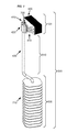
- FIG. 1 shows a particular perspective of a temperature-stabilized storage container 100 including a regulated thermal transfer device, according to an embodiment.
- FIG. 1 illustrates a side view of a temperature-stabilized storage container 100 from the exterior.
- the temperature-stabilized storage container 100 includes a regulated thermal transfer device including a circuitry unit 110 and a heat sink unit 120 visible in the exterior view of FIG. 1 .
- the temperature-stabilized storage container 100 also includes an external shell 130 attached to the top region of the temperature-stabilized storage container 100 .
- the external shell 130 includes a plurality of apertures positioned substantially vertically within the external shell 130 . In the view shown in FIG. 1 , a first aperture 140 and a second aperture 150 are visible.
- the first and second apertures 140 , 150 are positioned, inter alia, to serve as handholds for the temperature-stabilized storage container 100 for a user of the container, such as to move the position of the container within a room.
- a temperature-stabilized storage container includes a substantially thermally sealed storage container.
- U.S. patent application Ser. No. 13/906,909 entitled TEMPERATURE-STABILIZED STORAGE SYSTEMS WITH REGULATED COOLING, naming Jonathan Bloedow, Ryan Calderon, David Gasperino, William Gates, Roderick A. Hyde, Edward K. Y. Jung, Shieng Liu, Nathan P. Myhrvold, Nathan John Pegram, Clarence T. Tegreene, Charles Whitmer, Lowell L. Wood, Jr. and Ozgur Emek Yildirim as inventors, filed 31 May, 2013, which is incorporated by reference.
- a temperature-stabilized storage container can be of a portable size and shape, for example a size and shape within reasonable expected portability estimates for an individual person.
- the temperature-stabilized storage container can be configured of a size and shape for carrying or hauling by an individual person.
- the temperature-stabilized storage container has a mass that is less than approximately 50 kilograms (kg), or less than approximately 30 kg.
- the temperature-stabilized storage container has a length and width that are less than approximately 1 meter (m).
- the temperature-stabilized storage container 100 illustrated in FIG. 1 is roughly configured as a cylindrical shape, however multiple shapes are possible depending on the embodiment. For example, a rectangular shape, or an irregular shape, can be desirable in some embodiments, depending on the intended use of the temperature-stabilized storage container.
- a temperature-stabilized storage container includes a base attached to the exterior of the container at a region of the container positioned to be a lower region during expected use of the container.
- the temperature-stabilized storage container 100 illustrated in FIG. 1 includes a base 160 , which is configured to provide stability and balance to the temperature-stabilized storage container 100 .
- the base 160 can provide mass and therefore ensure stability of the temperature-stabilized storage container 100 in an upright position, or a position for its intended use.
- the base 160 can provide mass and form a stable support structure for the temperature-stabilized storage container 100 .
- the temperature-stabilized storage container 100 is configured to be maintained in a position so that the single access aperture to a substantially thermally sealed storage region is commonly maintained substantially at the highest elevated surface of the temperature-stabilized storage container. In embodiments such as that depicted in FIG. 1 , such positioning minimizes thermal transfer of heat from the region surrounding the temperature-stabilized storage container 100 into a storage region within the temperature-stabilized storage container 100 . In order to maintain the thermal stability of a storage region within the temperature-stabilized storage container 100 over time, thermal transfer of heat from the exterior of the temperature-stabilized storage container 100 into the temperature-stabilized storage container 100 is not desirable. A base 160 of sufficient mass can be configured to encourage maintenance of the temperature-stabilized storage container 100 in an appropriate position for the embodiment during use.
- a base 160 of sufficient mass can be configured to encourage maintenance of the temperature-stabilized storage container 100 in an appropriate position for minimal thermal transfer into a storage region within the temperature-stabilized storage container 100 from a region exterior to the temperature-stabilized storage container 100 .
- an external wall of an access conduit can be elongated and/or nonlinear to create an elongated thermal pathway between the exterior of the container 100 and the interior of the container.
- the temperature-stabilized storage container 100 can include, in some embodiments, one or more handles 170 attached to an exterior surface of the container 100 , wherein the handles 170 are configured for transport of the container 100 .
- the handles can be fixed on the surface of the container, for example welded, fastened or glued to the surface of the container.
- the handles can be operably attached but not fixed to the surface of the container, such as with a harness, binding, hoop or chain running along the surface of the container.
- the handles can be positioned to retain the container with an access conduit on the top of the container during transport to minimize thermal transfer from the exterior of the container through the access conduit.
- the temperature-stabilized storage container can include electronic components.
- FIG. 1 depicts a circuitry unit 110 positioned at the top of the container 100 .
- electronics with thermal emissions can be operably attached to the exterior of the container without providing heat to the interior of the container.
- FIG. 1 depicts a heat sink unit 120 positioned adjacent to the top edge of the container 100 .
- one or more positioning devices such as GPS devices, can be attached to the exterior of the container.
- One or more positioning devices can be configured as part of a system including, for example, monitors, displays, circuitry, power sources, an operator unit, and transmission units.
- circuitry is positioned within the interior region of a container during use of an embodiment, it is selected for low thermal emission properties as well as positioned and utilized to minimize thermal emissions.
- one or more power sources can be attached to the temperature-stabilized storage container, wherein the power source is configured to supply power to circuitry within the container or within a regulated thermal transfer device affixed to the container.
- a photovoltaic unit can be attached to the exterior surface of the temperature-stabilized storage container.
- a photovoltaic unit can be attached to a building or structure that the container is placed within, and a wire or similar electrical conduit can connect the circuitry within the container or within a regulated thermal transfer device affixed to the container to the external photovoltaic unit.
- a battery unit can be attached to the exterior surface of the temperature-stabilized storage container.
- one or more wires can be positioned within an access conduit of the temperature-stabilized storage container to supply power to circuitry within the container or within a regulated thermal transfer device affixed to the temperature-stabilized storage container.
- one or more power sources can be attached to an exterior surface of the temperature-stabilized storage container, wherein the power source is configured to supply power to circuitry within the container.
- one or more power sources can be attached to an exterior surface of the temperature-stabilized storage container, wherein the power source is configured to supply power to circuitry integral to a regulated thermal transfer device affixed to the temperature-stabilized storage container.
- a power source can include wirelessly transmitted power sources, such as described in U.S. Patent Application No.
- a power source can include a magnetically transmitted power source.
- a power source can include a battery.
- a power source can include a solar panel, such as a photovoltaic panel.
- a power source can include an AC power source with a converter to supply DC current to the circuitry within the temperature-stabilized storage container or within a regulated thermal transfer device affixed to the temperature-stabilized storage container.
- one or more temperature sensors can be attached to an exterior surface of the temperature-stabilized storage container.
- the one or more temperature sensors can be configured, for example, to display the ambient temperature at the surface of the temperature-stabilized storage container.
- the one or more temperature sensors can be configured, for example, to transmit data to one or more system.
- the one or more temperature sensors can be configured, for example, as part of a temperature monitoring system.
- one or more transmission units can be operably attached to the temperature-stabilized storage container.
- one or more transmission units can be operably attached to the exterior surface of the temperature-stabilized storage container.
- one or more transmission units can be operably attached to an interior unit within the temperature-stabilized storage container.
- one or more transmission units can be operably attached to the regulated thermal transfer device affixed to the temperature-stabilized storage container.
- one or more receiving units can be operably attached to the temperature-stabilized storage container.
- one or more receiving units can be operably attached to the exterior surface of the temperature-stabilized storage container.
- one or more receiving units can be operably attached to an interior unit within the temperature-stabilized storage container.
- one or more receiving units can be operably attached to the regulated thermal transfer device affixed to the temperature-stabilized storage container.
- FIG. 2 depicts an isometric external view of a temperature-stabilized storage container 100 .
- the temperature-stabilized storage container 100 includes a regulated thermal transfer device including a circuitry unit 110 and a heat sink unit 120 visible in the exterior view of FIG. 2 .
- the heat sink unit 120 includes a plurality of linear slits in a cover of the heat sink unit 120 , the plurality of slits positioned to provide air flow between a region adjacent to the heat sink unit 120 and the interior of the heat sink unit 120 .
- the temperature-stabilized storage container 100 also includes an external shell 130 attached to the top region of the temperature-stabilized storage container 100 .
- the external shell 130 includes a plurality of apertures positioned substantially vertically within the external shell 130 . The embodiment shown in FIG.
- the 2 includes a plurality of handles 170 affixed to the exterior of the temperature-stabilized storage container 100 .
- the embodiment illustrated includes a base 160 affixed to a lower region of the temperature-stabilized storage container 100 .
- the external shell 130 and the base 160 are affixed to distal ends of the temperature-stabilized storage container 100 illustrated in FIG. 2 .
- FIG. 3 illustrates an embodiment of a temperature-stabilized storage container 100 in a top-down view.
- the temperature-stabilized storage container 100 includes a regulated thermal transfer device including a circuitry unit 110 and a heat sink unit 120 visible in the view of FIG. 3 .
- the heat sink unit 120 includes a plurality of slits in the visible cover to the heat sink unit, the slits positioned to provide airflow through the cover.
- a lid 300 covers a single access aperture to the interior storage region within the temperature-stabilized storage container 100 .
- the lid 300 is attached to hinges 310 positioned to move the lid 300 as desired by a user to access the interior storage region of the container.
- FIG. 4 shows an embodiment of temperature-stabilized storage container 100 in a top-down view.
- the circuitry unit 110 and a heat sink unit 120 of a regulated thermal transfer device integral to the container do not include covers.
- the interior regions of the circuitry unit 110 and the heat sink unit 120 are partially illustrated in the view of FIG. 4 .
- the heat sink unit 120 includes a plurality of planar thermal transfer units positioned substantially horizontally relative to the usual orientation of the container (e.g. as shown in FIG. 1 ).
- a top thermal transfer unit 400 is visible in the view of FIG. 4 as a substantially planar sheet.
- the heat sink unit 120 also includes a plurality of heat pipes 410 affixed to a heat transfer unit 420 .
- the heat transfer unit 420 includes a thermally-conductive block surrounding a top end of a heat pipe 430 .
- the heat pipe 430 is positioned substantially at right angles to the view shown in FIG. 4 , so in this view it is visible as a circular cross-section of the heat pipe 430 .
- FIG. 5 illustrates an external view of a portion of a regulated thermal transfer device 500 .
- the regulated thermal transfer device 500 portion shown in FIG. 5 is attached to a temperature-stabilized storage container during use, along with an attached circuitry unit (not shown in FIG. 5 ).
- the regulated thermal transfer device is of a size and shape to be positioned so that the phase change material unit is within a storage region of a temperature-stabilized storage container during use of the device.
- the regulated thermal transfer device 500 illustrated in FIG. 5 includes an external cover surrounding the structure.
- the regulated thermal transfer device 500 shown in FIG. 5 is attached to a circuitry unit during use with a temperature-stabilized storage container.
- the heat sink unit 120 includes a plurality of slits in the top portion of the cover surrounding the heat sink unit 120 .
- the slits create apertures through the cover at the top of the heat sink unit 120 .
- the heat sink unit 120 is affixed at its lower edge to an adiabatic region 510 of the regulated thermal transfer device 500 .
- the adiabatic region 510 includes a cover with a surface 520 configured to reversibly mate with the interior surface of an access conduit of a temperature-stabilized storage container during use of the device with the container.
- the portion of a regulated thermal transfer device 500 shown in FIG. 5 includes a phase change material unit 530 .
- the phase change material unit 530 includes walls surrounding a phase-change material region interior to the walls.
- a regulated thermal transfer device includes a phase change material unit, the phase change material unit including one or more walls surrounding a phase-change material region, and an aperture in the one or more walls.
- the phase change material unit includes an aperture surrounding a heat pipe, and a seal connecting the aperture to the heat pipe.
- the phase change material unit includes a sealed container substantially filled with a phase-change material.
- the phase change material unit includes a sealed container including a hydrocarbon-based phase-change material within an expanded graphite structure.
- the phase change material unit includes an attachment region positioned to attach the phase change material unit to a surface of the storage region of the temperature-stabilized storage container.
- the external cover of the phase change material unit can include one or more fasteners positioned to mate with the interior surface of the storage region of the temperature-stabilized storage container.
- the phase change material unit includes a phase change material substantially filling a sealed interior region of the phase change material unit, the phase change material having a freeze temperature between about 0° C. to about 2° C. In some embodiments, the phase change material has a freeze temperature between about 1° C. to about 3° C. In some embodiments, the phase change material has a freeze temperature between about 2° C. to about 4° C.
- the phase change material has a freeze temperature between about 3° C. to about 5° C. In some embodiments, the phase change material has a freeze temperature between about 4° C. to about 6° C. In some embodiments, the phase change material unit includes a phase change material as well as expansion space sufficient to include the phase change material in a different phase. For example, in some embodiments the phase change material includes water and the phase change material unit includes sufficient expansion space to contain the water in a frozen state.
- the phase change material unit includes additional material positioned in a location to encourage freezing of the phase change material at that location.
- the phase change material unit includes one or more nucleation agents.
- a phase change material unit can include water as a phase change material and nucleation agents, such as silver iodide or plant-based nucleating agents such as Ina proteins from Pseudomonas syringae .
- the phase change material unit includes a mechanical shock unit, such as a piezo actuator or a solenoid unit positioned to nucleate ice formation in supercooled phase change material, such as water.
- a phase change material includes a second thermoelectric unit positioned to provide additional cooling to the phase change material unit.
- Phase change material includes materials that change their state (e.g. liquid to solid) at specific temperatures with a high heat of fusion.
- the phase change material is water or ice.
- the phase change material is an organic or inorganic material.
- the phase change material for an embodiment can be selected based on factors such as cost, thermal capacity, toxicity, mass and freezing temperature for a specific phase change material.
- a phase change material includes PureTempTM 4 (available from Entropy Solutions Inc.), with a melting point of 5° C.
- a phase change material includes Phase 5TM, (available from Cryopak Inc.), with a melting point of 5° C.
- a phase change material includes materials with a melting point up to 8° C. In some embodiments a phase change material includes materials with a melting point between 2° C. and 8° C. In some embodiments, the phase change material is a hydrocarbon-based material. In some embodiments, the phase change material is a salt-water solution. In some embodiments, the phase change material is a salt-hydrate solution, wherein the salt is present in a crystalline form. In some embodiments, the phase change material is a salt eutectic solution. In some embodiments, the phase change material includes one or more clathrates, for example tetrahydrofuran clathrate. In some embodiments, the phase change material is structured as beads or pellets within the phase change material unit.
- the phase change material is structured as a solid or semi-solid three-dimensional unit within the phase change material unit, so that no internal containment structure for the phase change material is required.
- a phase change material can be structured as a semi-solid gel, or a solid crystalline array.
- a phase change material unit can include one or more additional elements positioned to enhance thermal transfer within the phase change material unit.
- the phase change material unit includes an expanded graphite material saturated with a hydrocarbon-based phase change material.
- one or more 10% graphite sheets can be saturated with a hydrocarbon-based phase change material and the combined materials positioned within a phase change material unit.
- a phase change material unit can include one or more thermal conduction elements, such as plate structures, linear structures, or other features fabricated from thermally-conductive material and positioned within the phase change material unit in a manner to enhance thermal transfer within the phase change material unit.
- a phase change material unit can include one or more mesh structures fabricated from copper and positioned to enhance thermal transfer within the phase change material unit.
- phase change material unit illustrated in FIG. 5 is a solid structure.
- a phase change material unit is a folded or compressed structure that is unfolded or expanded during addition of the regulated thermal transfer device to a temperature-stabilized storage container.
- a phase change material unit includes a balloon-type structure that is initially inserted into the storage region interior to a temperature-stabilized storage container without phase change material (e.g. in a “deflated” state). Subsequently, the phase change material unit can be filled with a phase change material, such as through a tube positioned within the adiabatic region of the regulated thermal transfer device. As the balloon-type structure of the phase change material unit is filled with the phase change material, it expands in position within the storage region interior to a temperature-stabilized storage container in a manner for use.
- a regulated thermal transfer device also includes a phase change material unit with a second internal container including phase change material.
- a second internal container can include the same phase change material as the main container.
- a second internal container can include a second phase change material.
- the second internal container can include an internal enclosure with phase change material sealed within the internal closure.
- a phase change material unit includes a plurality of internal containers, each including phase change material.
- the phase change material can be the same in each of the plurality of internal containers.
- the phase change material can be different among the plurality of internal containers.
- the one or more internal containers within the phase change material unit can be positioned, for example, between the exterior of the phase change material unit and the heat pipe within the phase change material unit.
- the one or more internal containers within the phase change material unit can be positioned, for example, between the internal storage region of the container and the heat pipe within the phase change material unit.
- a regulated thermal transfer device also includes a heat pipe with a first end positioned within the phase change material unit, and a second end traversing the aperture of the one or more walls of the phase change material unit.
- the heat pipe includes a substantially tubular structure.
- the heat pipe includes a substantially vertical structure when the regulated thermal transfer device is positioned for use within a storage container. See, e.g. FIGS. 12 and 13 .
- the heat pipe is configured to be positioned substantially vertically when it is affixed to the temperature-stabilized storage container.
- the heat pipe includes a plurality of thermal conduction structures positioned within the phase-change material unit and configured to transfer heat from the phase change material to the heat pipe.
- a heat pipe has a plurality of planar thermal conduction structures thermally attached to its outer surface.
- the thermal conduction structures can be fabricated from a thermally-conductive material, such as copper or silver.
- the heat pipe includes a plurality of thermal conduction structures including a plurality of planar structures attached to the heat pipe at substantially right angles.
- a regulated thermal transfer device also includes a thermoelectric unit thermally connected to the second end of the heat pipe.
- the thermoelectric unit is positioned adjacent to an external surface of the temperature-stabilized storage container.
- the thermoelectric unit includes a Peltier device.
- the thermoelectric unit is positioned to transfer thermal energy away from the second end of the heat pipe.
- the thermoelectric unit is positioned to transfer thermal energy to the heat sink connected to the thermoelectric unit.
- the thermoelectric unit can include a side in thermal contact with a heat sink.
- a regulated thermal transfer device also includes a heat sink connected to the thermoelectric unit, and positioned to radiate heat away from the thermoelectric unit.
- the heat sink includes a passive heat sink device.
- a passive heat sink can include unpowered components, such as radiative fins, a heat block, and one or more heat pipes positioned to radiate heat away from the thermoelectric unit.
- the heat sink includes an active heat sink device, the active heat sink device operably coupled to the controller.
- an active heat sink device can include one or more fan units positioned to circulate air and thereby radiate heat away from the thermoelectric unit.
- a fan is attached to a shell (see, e.g. shell 130 in FIG. 1 ) in a position adjacent to an aperture in the shell (see, e.g. apertures 140 , 150 in FIG. 1 ) and in a position to direct air through the aperture and away from the thermoelectric unit.
- a regulated thermal transfer device also includes an electronic controller operably connected to the thermoelectric unit.
- an electronic controller is included within a circuitry unit (see, e.g. FIGS. 1 through 4 ).
- an electronic controller includes circuitry configured to control the thermoelectric unit of the regulated thermal transfer device.
- an electronic controller includes circuitry configured to control the thermoelectric unit in response to signals received from at least one temperature sensor.
- an electronic controller includes circuitry configured to control the thermoelectric unit in response to signals received from at least one temperature sensor attached to the cover of the phase change material unit.
- an electronic controller includes circuitry configured to control the thermoelectric unit in response to signals received from at least one temperature sensor attached to the interior of a storage region of the temperature-stabilized storage container.
- a regulated thermal transfer device also include a temperature sensor attached to the phase change material unit; and a connector between the temperature sensor and the electronic controller.
- an electronic temperature sensor can be attached to the wall of a phase change material unit and a wire connector can be positioned within the phase change material unit, traversing the adiabatic region of the regulated thermal transfer device, and connected to an electronic controller within the attached a circuitry unit.
- Some embodiments of a regulated thermal transfer device also include a connector attached to the electronic controller, the connector configured to provide electricity to the regulated thermal transfer device from an external power source.
- an external power source includes a photovoltaic unit.
- an external power source includes a battery.
- an external power source includes a municipal power supply.
- a regulated thermal transfer device also include a communications unit operably coupled to the electronic controller.
- a communications unit can include a transmitter, such as a BluetoothTM transmitter.
- a communications unit can include a receiver.
- a communications unit can include an antenna.
- a communications unit can include a digital memory device.
- a regulated thermal transfer device also include a second phase change material unit including one or more walls surrounding a phase-change material region, and an aperture in the one or more walls, and a second heat pipe with a first end positioned within the second phase change material unit, and a second end thermally connected to the thermoelectric unit.
- the second phase change material unit can be configured, for example, to be positioned distal to the first phase change material unit within a storage region of the temperature-stabilized storage container.
- the second phase change material unit can be configured, for example, to be positioned within a second storage region of the temperature-stabilized storage container.
- FIG. 6 illustrates an external view of a portion of an embodiment of a regulated thermal transfer device 500 .
- the regulated thermal transfer device 500 portion shown in FIG. 6 is attached to a temperature-stabilized storage container along with an attached circuitry unit (not shown in FIG. 6 ).
- the regulated thermal transfer device 500 shown in FIG. 6 includes an external cover surrounding the structure.
- the portion of a regulated thermal transfer device 500 shown in FIG. 6 includes a heat sink unit 120 at the top of the device 500 .
- the heat sink unit 120 is affixed at its lower edge to an adiabatic region 510 of the regulated thermal transfer device 500 .
- the adiabatic region 510 includes a cover with a surface 520 configured to reversibly mate with the interior surface of an access conduit of a temperature-stabilized storage container during use of the device with the container.
- the portion of a regulated thermal transfer device 500 shown in FIG. 6 includes a phase change material unit 530 .
- FIG. 7 illustrates a portion of an embodiment of a regulated thermal transfer device 500 .
- the regulated thermal transfer device 500 shown in FIG. 7 has the cover removed to illustrate interior features of the regulated thermal transfer device 500 .
- the regulated thermal transfer device 500 includes a heat sink unit 120 at the top of the device 500 .
- the top end of a heat pipe 430 is positioned within the heat sink unit 120 .
- a heat transfer unit 420 is in physical contact with the top end of the heat pipe 430 .
- the heat sink unit 120 includes a thermal transfer unit 400 .
- the heat sink unit 120 also includes a plurality of heat pipes 410 affixed to the heat transfer unit 420 , the heat pipes 410 also attached to the thermal transfer unit 400 .
- thermoelectric device 700 is thermally connected to the top end of the heat pipe 430 .
- the thermoelectric unit 700 is positioned to transfer heat from the top end of the heat pipe 430 to the thermal transfer unit 400 .
- the thermoelectric unit 700 is a Peltier device.
- FIG. 7 illustrates that the regulated thermal transfer device 500 includes an adiabatic region 510 .
- an adiabatic region includes one or more wires, one or more tubes, or other features described elsewhere within.
- the adiabatic region 510 includes an adiabatic section of the heat pipe 430 .
- FIG. 7 shows that the regulated thermal transfer device 500 includes a phase change material unit 530 at the lower end of the regulated thermal transfer device 500 .
- the phase change material unit 530 would include a phase change material, not shown in FIG. 7 .
- the phase change material unit 530 includes a plurality of planar structures 710 attached to the heat pipe 430 at substantially right angles.
- the plurality of planar structures 710 are configured to enhance thermal efficiency through the phase change material unit 530 .
- Some embodiments include a plurality of planar structures 710 that are fabricated from a thermally-conductive material, such as copper, silver, or aluminum.
- Some embodiments include a plurality of planar structures 710 that includes a plurality of apertures, such as mesh structures.
- FIG. 8 illustrates a portion of an embodiment of a regulated thermal transfer device 500 with the cover removed to depict interior aspects of the device.
- the regulated thermal transfer device 500 includes a heat sink unit 120 at the top of the device 500 .
- the regulated thermal transfer device 500 depicted includes an adiabatic region 510 in the center of the device.
- the regulated thermal transfer device 500 shown includes a phase change material unit 530 at the lower end of the device.
- the heat sink unit 120 includes a heat transfer unit 420 positioned in physical contact with the top end of the heat pipe 430 .
- the heat sink unit 120 includes a thermal transfer unit 400 .
- the heat sink unit 120 also includes a plurality of heat pipes 410 affixed to the heat transfer unit 420 , the heat pipes 410 also attached to the thermal transfer unit 400 .
- a thermoelectric device 700 is thermally connected to the top end of the heat pipe 430 .
- the thermoelectric unit 700 is positioned to transfer heat from the top end of the heat pipe 430 to the thermal transfer unit 400 .
- the heat pipe 430 traverses the adiabatic region 510 and includes a lower end within the phase change material unit 530 .
- the phase change material unit 530 includes a plurality of planar structures 710 connected to the lower region of the heat pipe 430 and positioned to improve thermal transfer between the heat pipe 430 and phase change material (not shown) within the phase change material unit 530 .
- FIG. 9 illustrates a substantially cross-section view of a portion of a regulated thermal transfer device 500 .
- the embodiment illustrated includes a cover 900 surrounding the exterior of the shown regulated thermal transfer device 500 .
- a cover can be configured as a thin wall or shell surrounding the exterior of the regulated thermal transfer device.
- a cover can be fabricated from a sturdy plastic or fiberglass material.
- the portion of a regulated thermal transfer device 500 shown in FIG. 9 includes a heat sink unit 120 , an adiabatic region 510 and a phase change material unit 530 .
- the heat sink unit 120 illustrated in FIG. 9 includes a heat transfer unit 420 positioned in physical contact with the top end of the heat pipe 430 .
- the heat sink unit 120 includes a thermal transfer unit 400 .
- the heat sink unit 120 also includes a plurality of heat pipes 410 affixed to the heat transfer unit 420 , the heat pipes 410 also attached to the thermal transfer unit 400 .
- a thermoelectric device 700 is thermally connected to the top end of the heat pipe 430 .
- the thermoelectric unit 700 is positioned to transfer heat from the top end of the heat pipe 430 to the thermal transfer unit 400 .
- the embodiment illustrated includes a heat pipe 430 traversing the adiabatic region 510 within the cover 900 .
- the heat pipe 430 includes a lower end substantially coexistent with the lower face of the phase change material unit 530 .
- the phase change material unit 530 includes a plurality of planar structures 710 connected to the lower region of the heat pipe 430 and positioned to improve thermal transfer between the heat pipe 430 and phase change material (not shown) within the phase change material unit 530 .
- phase change material (not shown) would substantially fill the interior of the phase change material unit 530 substantially up to the edge of the adiabatic region 510 .
- FIG. 10 shows aspects of a partial embodiment of a regulated thermal transfer device 500 as a substantially cross-section view.
- the regulated thermal transfer device 500 is positioned within and attached to a temperature-stabilized storage container along with an attached circuitry unit (not shown in FIG. 10 ).
- the embodiment illustrated includes a cover 900 surrounding the exterior of the shown regulated thermal transfer device 500 .
- the portion of a regulated thermal transfer device 500 shown in FIG. 10 includes a heat sink unit 120 , an adiabatic region 510 and a phase change material unit 530 .
- the heat sink unit 120 includes a heat transfer unit 420 in direct thermal contact with the top end of the heat pipe 430 .
- the heat sink unit 120 includes a thermal transfer unit 400 .
- the heat sink unit 120 also includes a plurality of heat pipes 410 affixed to the heat transfer unit 420 .
- the heat pipes 410 are embedded in the thermal transfer unit 400 and positioned to effectuate thermal transfer from the heat pipes 410 to the thermal transfer unit 400 .
- a thermoelectric device 700 is thermally connected to the top end of the heat pipe 430 .
- the thermoelectric device 700 is connected to a controller in an attached circuitry unit (not shown in FIG. 10 ). During use, the controller regulates the operation of the thermoelectric device 700 in response to input from at least one temperature sensor.
- one or more temperature sensors can be placed adjacent to the cover 900 of the phase change material unit 530 and connected to an attached circuitry unit with a wire connector.
- the embodiment illustrated in FIG. 10 includes a phase change material unit 530 .
- the phase change material unit 530 includes a cover 900 surrounding the exterior of the phase change material unit 530 .
- the cover of the phase change material unit is contiguous with the cover of the entire regulated thermal transfer device.
- the phase change material unit 530 includes a plurality of thermal conduction structures 710 positioned within the phase-change material unit 530 . Interspersed with the plurality of thermal conduction structures 710 is an enhanced thermal transfer material 1000 including expanded graphite saturated with a phase change material.
- the enhanced thermal transfer material is in direct contact with the outer surface of the heat pipe 430 as well as the surfaces of the plurality of thermal conduction structures 710 .
- FIG. 11 illustrates part of an embodiment of a regulated thermal transfer device 500 as a substantially cross-section view.
- the regulated thermal transfer device 500 is positioned within and attached to a temperature-stabilized storage container along with an attached circuitry unit (not shown in FIG. 11 ).
- the embodiment illustrated includes a cover 900 surrounding the exterior of the shown regulated thermal transfer device 500 .
- the portion of a regulated thermal transfer device 500 shown in FIG. 11 includes a heat sink unit 120 , an adiabatic region 510 and a phase change material unit 530 .
- the heat sink unit 120 includes a heat transfer unit 420 in direct thermal contact with the top end of a heat pipe 430 , and a thermal transfer unit 400 in thermal contact with the heat transfer unit 420 through a plurality of heat pipes 410 affixed to the heat transfer unit 420 .
- a thermoelectric device 700 is thermally connected to the top end of the heat pipe 430 , in direct contact with the heat transfer unit 420 .
- the phase change material unit 530 includes a cover 900 substantially defining the outer boundary of the phase change material unit 530 .
- the lower end of the heat pipe 430 traverses the interior of the phase change material unit 530 .
- the lower end of the heat pipe 430 traverses the interior of the phase change material unit 530 substantially through the center of the interior of the phase change material unit 530 .
- Surrounding the region of the heat pipe 430 within the phase change material unit 530 is an enhanced thermal transfer material 1000 including expanded graphite saturated with a phase change material.
- the enhanced thermal transfer material 1000 is in direct contact with the outer surface of the heat pipe 430 throughout the length of the heat pipe 430 within the phase change material unit 530 .
- FIG. 12 illustrates an embodiment of a regulated thermal transfer device 500 within a temperature-stabilized storage container 100 in a substantially cross-section view.
- the temperature-stabilized storage container 100 includes an outer wall 1250 substantially defining an outer surface of the storage container 100 , the outer wall 1250 including an outer aperture in an upper region (e.g. adjacent to the lid 300 ).
- the temperature-stabilized storage container 100 includes an inner wall 1260 substantially defining a temperature-stabilized storage region 1230 internal to the storage container 100 , the inner wall 1260 including an inner aperture in an upper region (e.g. adjacent to the junction with the internal conduit 1200 ).
- the temperature-stabilized storage container 100 includes a gap 1210 between the outer wall 1250 and the inner wall 1260 , and a conduit 1200 connecting the outer aperture to the inner aperture.
- One or more sections of ultra-efficient insulation material are positioned within the gap 1210 .
- the regulated thermal transfer device 500 within the temperature-stabilized storage container 100 includes a phase-change material unit 530 attached to an internal surface of the temperature-stabilized storage region 1230 .
- the regulated thermal transfer device 500 within the temperature-stabilized storage container 100 includes a heat pipe 430 with a first end positioned within the phase-change material unit 530 , and a second end positioned adjacent to the outer aperture.
- the regulated thermal transfer device 500 within the temperature-stabilized storage container 100 includes a thermoelectric unit 700 in contact with the second end of the heat pipe 430 , and a heat sink unit 120 connected to the thermoelectric unit 700 and positioned to radiate heat away from the thermoelectric unit 700 .
- the regulated thermal transfer device 500 also includes an electronic controller connected to the thermoelectric unit 700 . In the illustrated embodiment, the electronic controller is positioned within the circuitry unit 110 .
- a temperature-stabilized storage container includes wherein the conduit is substantially vertical when the temperature-stabilized storage container is positioned for use.
- the conduit 1200 is substantially vertical, and generally maintains that position during use.
- the adiabatic region 510 of the regulated thermal transfer device 500 shown in FIG. 12 includes a surface 520 positioned to reversibly mate with the interior surface of the conduit 1200 .
- the base 160 assists in maintaining the position of the entire temperature-stabilized storage container 100 , including the internal conduit 1200 .
- the conduit is of a size and shape to permit insertion and removal of a medicinal vial package with minimal excess space. For example, in the embodiment shown in FIG.
- a temperature-stabilized storage container includes wherein the conduit is a substantially tubular shape with a diameter between approximately 4 centimeters and approximately 6 centimeters. In some embodiments, a temperature-stabilized storage container includes wherein the conduit is a substantially tubular shape with a diameter between approximately 5 centimeters and approximately 7 centimeters.
- a temperature-stabilized storage container includes wherein the conduit is a substantially tubular shape with a diameter between approximately 12 centimeters and approximately 13 centimeters. In some embodiments, a temperature-stabilized storage container includes wherein the conduit is a substantially tubular shape with a diameter between approximately 10 centimeters and approximately 15 centimeters.
- a temperature-stabilized storage container includes at least one section of ultra-efficient insulation material.
- a temperature-stabilized storage container includes one or more sections of ultra-efficient insulation material substantially defining a temperature-stabilized storage container including a temperature-stabilized storage region with a single access aperture to the temperature-stabilized storage region.
- at least one section of ultra-efficient insulation material can be positioned within the gap 1210 .
- a temperature-stabilized storage container includes at least one section of ultra-efficient insulation material within the gap including: a plurality of layers of multilayer insulation substantially surrounding the thermally sealed storage region; and substantially evacuated space surrounding the plurality of layers of multilayer insulation.
- a temperature-stabilized storage container includes at least one section of ultra-efficient insulation material within the gap including one or more sections of an aerogel.
- a temperature-stabilized storage container includes a temperature-stabilized storage region that is configured to be maintained at a temperature substantially between approximately 2 degrees Centigrade and approximately 8 degrees Centigrade.
- a temperature-stabilized storage container includes a temperature-stabilized storage region that is configured to be maintained at a temperature substantially between approximately 0 degrees Centigrade and approximately 10 degrees Centigrade.
- a temperature-stabilized storage container includes a temperature-stabilized storage region that is configured to be maintained at a temperature substantially between approximately 3 degrees Centigrade and approximately 7 degrees Centigrade.
- a temperature-stabilized storage region can be configured to be maintained within a temperature range based on operation of the regulated thermal transfer device attached to the container.
- FIG. 13 illustrates an embodiment of a regulated thermal transfer device 500 within a temperature-stabilized storage container 100 in a substantially cross-section view.
- the temperature-stabilized storage container 100 includes an outer wall 1250 substantially defining an outer surface of the storage container 100 , the outer wall 1250 including an outer aperture in an upper region. The outer aperture is closed with a removable lid 300 .
- the temperature-stabilized storage container 100 includes an inner wall 1260 substantially defining a temperature-stabilized storage region 1230 internal to the storage container 100 , the inner wall 1260 including an inner aperture in an upper region.
- a storage unit 1220 including medicinal material in packaging 1240 is positioned adjacent to the inner aperture.
- the temperature-stabilized storage container 100 includes a gap 1210 between the outer wall 1250 and the inner wall 1260 , and a conduit 1200 connecting the outer aperture to the inner aperture.
- One or more sections of ultra-efficient insulation material are positioned within the gap 1210 .
- the regulated thermal transfer device 500 within the temperature-stabilized storage container 100 includes a phase-change material unit 530 attached to an internal surface of the temperature-stabilized storage region 1230 .
- the regulated thermal transfer device 500 within the temperature-stabilized storage container 100 includes a heat pipe 430 with a first end positioned within the phase-change material unit 530 , and a second end positioned adjacent to the outer aperture.
- the regulated thermal transfer device 500 within the temperature-stabilized storage container 100 includes a thermoelectric unit 700 in contact with the second end of the heat pipe 430 , and a heat sink unit 120 connected to the thermoelectric unit 700 and positioned to radiate heat away from the thermoelectric unit 700 .
- the regulated thermal transfer device 500 also includes an electronic controller connected to the thermoelectric unit 700 . In the illustrated embodiment, the electronic controller is positioned within the circuitry unit 110 .
- FIG. 14 illustrates a cross-section view substantially horizontally through a phase-change material unit 530 of a regulated thermal transfer device within a temperature-stabilized storage container 100 .
- the temperature-stabilized storage container 100 includes an outer wall 1250 surrounded by a base 160 .
- the temperature-stabilized storage container 100 includes an inner wall 1260 positioned within the outer wall 1250 .
- a gap 1210 exists between the inner wall 1260 and the outer wall 1250 .
- at least one section of ultra-efficient insulation material is positioned within the gap 1210 .
- the inner wall 1260 substantially defines a temperature-stabilized storage region 1230 within the container 100 .
- a series of storage units 1220 A, 1220 B, 1220 C are positioned adjacent to each other within the temperature-stabilized storage region 1230 .
- a phase-change material unit 530 of a regulated thermal transfer device is attached to the inner surface of the inner wall 1260 .
- the phase-change material unit 530 is surrounded by a cover 900 and includes an interior heat pipe 430 .
- FIG. 15 illustrates positioning of a plurality of storage units within a temperature-stabilized storage container including a regulated thermal transfer device.
- the plurality of storage units 1220 A, 1220 B, 1220 C, 1220 D, 1220 E, 1220 F, 1220 G and 1220 H are collectively referred to as “storage units 1220 ” with reference to the Figures herein.
- the inner wall 1260 of a temperature-stabilized storage container including a regulated thermal transfer device substantially defines the perimeter of a temperature-stabilized storage region 1230 .
- a phase-change material unit 530 of a regulated thermal transfer device is attached to the inner surface of the inner wall 1260 .
- the phase-change material unit 530 includes an external cover 900 .
- the phase-change material unit 530 includes a heat pipe 430 positioned within the interior of the phase-change material unit 530 .
- the storage units 1220 are shaped and positioned to substantially fill the interior space of the temperature-stabilized storage region 1230 .
- the storage units 1220 are not all shaped identically. All of the storage units 1220 are sized and shaped to individually fit through the conduit 1200 , the diameter of which is shown in FIG. 15 for purposes of illustration.
- the circuitry unit includes one or more controllers and one or more memory units.
- the regulated thermal transfer device may control the temperature in the temperature-stabilized storage region by controlling operation of the one or more thermoelectric unit integral to the regulated thermal transfer device.
- a controller of the circuitry unit can include at least one processor coupled to a power source (e.g., a photovoltaic panel) and to a power management unit.
- the controller can include a processor configured to direct a power management unit to provide power to the thermoelectric unit in response to input from a temperature sensor within the temperature-stabilized storage region of a temperature-stabilized storage container.
- thermoelectric unit may be connected at a power output connection to the circuitry unit.
- a controller within the circuitry unit may direct a power management unit to supply power to the power output connection and to the thermoelectric unit.
- the controller can control the temperature in the temperature-stabilized storage region of a temperature-stabilized storage container.
- the controller may direct the thermoelectric unit to remove heat from the phase change material unit until a predetermined portion of the phase change material is at a suitable temperature or is in a solid phase. Consequently, the controller can control the temperature in the storage compartment to within about ⁇ 1° C.
- the controller and the power management unit also may adjust or transform the power received from the power source to a suitable voltage or, for example, may convert the power to direct current.
- the power source may include a photovoltaic panel.
- the output voltage from the photovoltaic panel may vary (e.g., due to variance in exposure to light).
- the controller and the power management unit may convert the power received from the photovoltaic panel to a suitable voltage, which may be further supplied to other elements or components of the regulated thermal transfer device, such as to the controller and to the thermoelectric unit, among others.
- the circuitry unit may be programmed to receive varying or variable voltage from the power source and to regulate such voltage to further provide suitable voltage to the heat pump.
- the power output connection may be coupled to a memory, which may contain operating instructions for the power output connection.
- the memory may include instructions about desirable temperature or temperature distribution in the phase change material unit.
- the memory may include instructions that relate change in volume of the phase change material unit to a suitable temperature distribution therein.
- the phase change material unit may include a whase change material that is water. As water changes phase from liquid to solid, the total volume of the water in the phase change material unit will change. Furthermore, the initial volume of the water (e.g., when all of the water is in a liquid phase) may be known or stored in the memory. Accordingly, the circuitry unit may receive information about the volume (e.g., from one or more sensors) of the phase change material unit and may calculate change in volume. Moreover, the processor may calculate the amount of solid phase change material. Hence, the instructions stored in the memory may allow the processor to determine the amount of solid phase PCM or temperature distribution in the phase change material unit.
- the instructions stored in the memory also may allow the processor to use one or more temperature readings from the phase change material unit to control operation of the thermoelectric unit.
- the processor may receive a single or multiple temperature readings (e.g., from sensors) indicative of the temperature in one or more zones in the phase change material unit.
- the processor may stop operation of the thermoelectric unit.
- the memory may include instructions that may allow the processor to determine whether to direct power management unit to supply power to the thermoelectric unit connected at power output connection, thereby controlling the temperature in the phase change material unit and, thus, in the temperature-stabilized storage region of a temperature-stabilized storage container. For instance, the processor may maintain operation of the thermoelectric unit until reaching a predetermined temperature level (e.g., 3° C.).
- a predetermined temperature level e.g., 3° C.
- the memory also may include instructions regarding priority or hierarchy of power needs.
- the processor may use the priority instructions to direct the power management unit to provide power to elements or components indicated as having priority over other elements or components. For instance, the processor may give priority to providing power to the controller over the thermoelectric unit.
- the priority hierarchy may be as follows, listed from highest to lowest: controller (or battery attached to the controller, if any); thermoelectric unit of the heat sink unit, fan for the heat sink unit (if any); display unit (if any).
- the implementer may opt for a mainly hardware and/or firmware vehicle; alternatively, if flexibility is paramount, the implementer may opt for a mainly software (e.g., a high-level computer program serving as a hardware specification) implementation; or, yet again alternatively, the implementer may opt for some combination of hardware, software (e.g., a high-level computer program serving as a hardware specification), and/or firmware in one or more machines, compositions of matter, and articles of manufacture, limited to patentable subject matter under 35 U.S.C. ⁇ 101.
- a mainly software e.g., a high-level computer program serving as a hardware specification
- logic and similar implementations may include computer programs or other control structures.
- Electronic circuitry may have one or more paths of electrical current constructed and arranged to implement various functions as described herein.
- one or more media may be configured to bear a device-detectable implementation when such media hold or transmit device detectable instructions operable to perform as described herein.
- implementations may include an update or modification of existing software (e.g., a high-level computer program serving as a hardware specification) or firmware, or of gate arrays or programmable hardware, such as by performing a reception of or a transmission of one or more instructions in relation to one or more operations described herein.
- an implementation may include special-purpose hardware, software (e.g., a high-level computer program serving as a hardware specification), firmware components, and/or general-purpose components executing or otherwise invoking special-purpose components. Specifications or other implementations may be transmitted by one or more instances of tangible transmission media as described herein, optionally by packet transmission or otherwise by passing through distributed media at various times.
- implementations may include executing a special-purpose instruction sequence or invoking circuitry for enabling, triggering, coordinating, requesting, or otherwise causing one or more occurrences of virtually any functional operation described herein.
- operational or other logical descriptions herein may be expressed as source code and compiled or otherwise invoked as an executable instruction sequence.
- implementations may be provided, in whole or in part, by source code, such as C++, or other code sequences.
- source or other code implementation may be compiled//implemented/translated/converted into a high-level descriptor language (e.g., initially implementing described technologies in C or C++ programming language and thereafter converting the programming language implementation into a logic-synthesizable language implementation, a hardware description language implementation, a hardware design simulation implementation, and/or other such similar mode(s) of expression).
- a high-level descriptor language e.g., initially implementing described technologies in C or C++ programming language and thereafter converting the programming language implementation into a logic-synthesizable language implementation, a hardware description language implementation, a hardware design simulation implementation, and/or other such similar mode(s) of expression.
- a logical expression e.g., computer programming language implementation
- a Verilog-type hardware description e.g., via Hardware Description Language (HDL) and/or Very High Speed Integrated Circuit Hardware Descriptor Language (VHDL)
- VHDL Very High Speed Integrated Circuit Hardware Descriptor Language
- circuitry model which may then be used to create a physical implementation having hardware (e.g., an Application Specific Integrated Circuit).
- ASICs Application Specific Integrated Circuits
- FPGAs Field Programmable Gate Arrays
- DSPs digital signal processors
- some aspects of the embodiments disclosed herein, in whole or in part, can be equivalently implemented in integrated circuits, as one or more computer programs running on one or more computers (e.g., as one or more programs running on one or more computer systems), as one or more programs running on one or more processors (e.g., as one or more programs running on one or more microprocessors), as firmware, or as virtually any combination thereof, limited to patentable subject matter under 35 U.S.C.
- Examples of a signal bearing medium include, but are not limited to, the following: a recordable type medium such as a floppy disk, a hard disk drive, a Compact Disc (CD), a Digital Video Disk (DVD), a digital tape, a computer memory, etc.; and a transmission type medium such as a digital and/or an analog communication medium (e.g., a fiber optic cable, a waveguide, a wired communications link, a wireless communication link (e.g., transmitter, receiver, transmission logic, reception logic, etc.), etc.).
- a recordable type medium such as a floppy disk, a hard disk drive, a Compact Disc (CD), a Digital Video Disk (DVD), a digital tape, a computer memory, etc.
- a transmission type medium such as a digital and/or an analog communication medium (e.g., a fiber optic cable, a waveguide, a wired communications link, a wireless communication link (e.g., transmitter, receiver, transmission logic, reception
- electrical circuitry includes, but is not limited to, electrical circuitry having at least one discrete electrical circuit, electrical circuitry having at least one integrated circuit, electrical circuitry having at least one application specific integrated circuit, electrical circuitry forming a general purpose computing device configured by a computer program (e.g., a general purpose computer configured by a computer program which at least partially carries out processes and/or devices described herein, or a microprocessor configured by a computer program which at least partially carries out processes and/or devices described herein), electrical circuitry forming a memory device (e.g., forms of memory (e.g., random access, flash, read only, etc.)), and/or electrical circuitry forming
- any two components so associated can also be viewed as being “operably connected”, or “operably coupled,” to each other to achieve the desired functionality, and any two components capable of being so associated can also be viewed as being “operably couplable,” to each other to achieve the desired functionality.
- operably couplable include but are not limited to physically mateable and/or physically interacting components, and/or wirelessly interactable, and/or wirelessly interacting components, and/or logically interacting, and/or logically interactable components.
- one or more components may be referred to herein as “configured to,” “configured by,” “configurable to,” “operable/operative to,” “adapted/adaptable,” “able to,” “conformable/conformed to,” etc.
- configured to generally encompass active-state components and/or inactive-state components and/or standby-state components, unless context requires otherwise.
Abstract
Description
-
- The present application constitutes a continuation-in-part of U.S. patent application Ser. No. 13/906,909, entitled TEMPERATURE-STABILIZED STORAGE SYSTEMS WITH REGULATED COOLING, naming Jonathan Bloedow, Ryan Calderon, David Gasperino, William Gates, Roderick A. Hyde, Edward K. Y. Jung, Shieng Liu, Nathan P. Myhrvold, Nathan John Pegram, Clarence T. Tegreene, Charles Whitmer, Lowell L. Wood, Jr. and Ozgur Emek Yildirim as inventors, filed 31 May, 2013.
- The present application constitutes a continuation-in-part of U.S. patent application Ser. No. 12/658,579, entitled TEMPERATURE-STABILIZED STORAGE SYSTEMS, naming Geoffrey F. Deane, Lawrence Morgan Fowler, William Gates, Zihong Guo, Roderick A. Hyde, Edward K. Y. Jung, Jordin T. Kare, Nathan P. Myhrvold, Nathan Pegram, Nels R. Peterson, Clarence T. Tegreene, Charles Whitmer and Lowell L. Wood, Jr. as inventors, filed 8 Feb. 2010.
Claims (43)
Priority Applications (4)
| Application Number | Priority Date | Filing Date | Title |
|---|---|---|---|
| US14/098,886 US9447995B2 (en) | 2010-02-08 | 2013-12-06 | Temperature-stabilized storage systems with integral regulated cooling |
| CN201480066581.7A CN105814390A (en) | 2013-12-06 | 2014-12-01 | Temperature-stabilized storage systems with integral regulated cooling |
| PCT/US2014/067863 WO2015084701A1 (en) | 2013-12-06 | 2014-12-01 | Temperature-stabilized storage systems with integral regulated cooling |
| CN202210824840.4A CN115413188A (en) | 2013-12-06 | 2014-12-01 | Temperature-stabilized storage system with integrated regulated refrigeration |
Applications Claiming Priority (3)
| Application Number | Priority Date | Filing Date | Title |
|---|---|---|---|
| US12/658,579 US9205969B2 (en) | 2007-12-11 | 2010-02-08 | Temperature-stabilized storage systems |
| US13/906,909 US9372016B2 (en) | 2013-05-31 | 2013-05-31 | Temperature-stabilized storage systems with regulated cooling |
| US14/098,886 US9447995B2 (en) | 2010-02-08 | 2013-12-06 | Temperature-stabilized storage systems with integral regulated cooling |
Related Parent Applications (1)
| Application Number | Title | Priority Date | Filing Date |
|---|---|---|---|
| US13/906,909 Continuation-In-Part US9372016B2 (en) | 2010-02-08 | 2013-05-31 | Temperature-stabilized storage systems with regulated cooling |
Publications (2)
| Publication Number | Publication Date |
|---|---|
| US20140150464A1 US20140150464A1 (en) | 2014-06-05 |
| US9447995B2 true US9447995B2 (en) | 2016-09-20 |
Family
ID=50824083
Family Applications (1)
| Application Number | Title | Priority Date | Filing Date |
|---|---|---|---|
| US14/098,886 Active 2031-01-22 US9447995B2 (en) | 2010-02-08 | 2013-12-06 | Temperature-stabilized storage systems with integral regulated cooling |
Country Status (1)
| Country | Link |
|---|---|
| US (1) | US9447995B2 (en) |
Cited By (16)
| Publication number | Priority date | Publication date | Assignee | Title |
|---|---|---|---|---|
| US10188229B2 (en) | 2010-11-02 | 2019-01-29 | Ember Technologies, Inc. | Heated or cooled dishware and drinkware |
| US20190039811A1 (en) * | 2016-01-28 | 2019-02-07 | Va-Q-Tec Ag | Transport container system and transport container |
| USD865211S1 (en) * | 2014-12-09 | 2019-10-29 | United Kingdom Research And Innovation | Cryo puck |
| US10546266B1 (en) * | 2015-12-23 | 2020-01-28 | The Bose Family Trust | Controlled environment shipment container and tracking method |
| US10670323B2 (en) | 2018-04-19 | 2020-06-02 | Ember Technologies, Inc. | Portable cooler with active temperature control |
| US10743708B2 (en) | 2010-11-02 | 2020-08-18 | Ember Technologies, Inc. | Portable cooler container with active temperature control |
| US10973996B2 (en) | 2014-07-15 | 2021-04-13 | Ron Nagar | Devices, systems and methods for controlling conditions and delivery of substances |
| US10989466B2 (en) | 2019-01-11 | 2021-04-27 | Ember Technologies, Inc. | Portable cooler with active temperature control |
| US11077443B2 (en) | 2017-02-02 | 2021-08-03 | University Of Wyoming | Apparatus for temperature modulation of samples |
| US11118827B2 (en) | 2019-06-25 | 2021-09-14 | Ember Technologies, Inc. | Portable cooler |
| US11162716B2 (en) | 2019-06-25 | 2021-11-02 | Ember Technologies, Inc. | Portable cooler |
| US11298667B2 (en) * | 2018-07-05 | 2022-04-12 | Vorwerk & Co. Interholding Gmbh | Preparation vessel with a cooling device |
| US11560504B2 (en) | 2020-06-03 | 2023-01-24 | Alliance For Sustainable Energy, Llc | Salt hydrate-based phase change thermal energy storage and encapsulation thereof |
| US20230110020A1 (en) * | 2021-10-08 | 2023-04-13 | Simmonds Precision Products, Inc. | Heatsinks |
| US11668508B2 (en) | 2019-06-25 | 2023-06-06 | Ember Technologies, Inc. | Portable cooler |
| US11950726B2 (en) | 2023-01-20 | 2024-04-09 | Ember Technologies, Inc. | Drinkware container with active temperature control |
Families Citing this family (20)
| Publication number | Priority date | Publication date | Assignee | Title |
|---|---|---|---|---|
| WO2015095271A1 (en) * | 2013-12-17 | 2015-06-25 | All Cell Technologies, Llc | Flexible phase change material composite for thermal management systems |
| EP3126761A4 (en) * | 2014-04-04 | 2017-11-29 | Sunwell Engineering Company Limited | A storage unit for maintaining a generally constant temperature |
| US10639238B2 (en) | 2015-03-13 | 2020-05-05 | Fisher Clinical Services, Inc. | Passive cold storage container systems with packaging tray and retention plate |
| US10386127B2 (en) * | 2015-09-09 | 2019-08-20 | General Electric Company | Thermal management system |
| US20170219256A1 (en) * | 2016-02-02 | 2017-08-03 | Tokitae Llc | Thermal transfer devices, temperature stabilized containers including the same, and related methods |
| CA3022410A1 (en) * | 2016-04-27 | 2017-11-02 | David PENSAK | Thermal consistency systems and methods for the application of thermal support to a human or animal body or to an organ for transplantation |
| US10209009B2 (en) | 2016-06-21 | 2019-02-19 | General Electric Company | Heat exchanger including passageways |
| EP3635306B1 (en) | 2017-05-31 | 2022-04-20 | Carrier Corporation | Actively cooled device for small scale delivery |
| US11530849B2 (en) | 2017-10-06 | 2022-12-20 | Carrier Corporation | Responsive cooling based on external factors |
| KR102522375B1 (en) * | 2017-10-16 | 2023-04-18 | 삼성전자주식회사 | Electronic device for attachable and detachable module |
| US10487252B2 (en) | 2018-01-24 | 2019-11-26 | Microtek Laboratories, Inc. | Water based thermal cooling gels comprising a viscosity modifier and ice nucleating protein |
| US20220000097A1 (en) * | 2018-11-12 | 2022-01-06 | Rui DE BRITO ESTRELA | Insulator for preventing container damage and rupture caused by freezing of aqueous solutions containing biological materials |
| US11260953B2 (en) | 2019-11-15 | 2022-03-01 | General Electric Company | System and method for cooling a leading edge of a high speed vehicle |
| US11260976B2 (en) | 2019-11-15 | 2022-03-01 | General Electric Company | System for reducing thermal stresses in a leading edge of a high speed vehicle |
| US11267551B2 (en) | 2019-11-15 | 2022-03-08 | General Electric Company | System and method for cooling a leading edge of a high speed vehicle |
| US11427330B2 (en) | 2019-11-15 | 2022-08-30 | General Electric Company | System and method for cooling a leading edge of a high speed vehicle |
| US11352120B2 (en) | 2019-11-15 | 2022-06-07 | General Electric Company | System and method for cooling a leading edge of a high speed vehicle |
| US11745847B2 (en) | 2020-12-08 | 2023-09-05 | General Electric Company | System and method for cooling a leading edge of a high speed vehicle |
| US11407488B2 (en) | 2020-12-14 | 2022-08-09 | General Electric Company | System and method for cooling a leading edge of a high speed vehicle |
| US11577817B2 (en) | 2021-02-11 | 2023-02-14 | General Electric Company | System and method for cooling a leading edge of a high speed vehicle |
Citations (209)
| Publication number | Priority date | Publication date | Assignee | Title |
|---|---|---|---|---|
| US520584A (en) | 1894-05-29 | Adjustable curtain-rod | ||
| US1903171A (en) | 1932-01-07 | 1933-03-28 | Zero Ice Corp | Solid co. receptacle |
| US2161295A (en) | 1936-09-05 | 1939-06-06 | Charles A Hirschberg | Container |
| US2496296A (en) | 1945-11-01 | 1950-02-07 | Lobl Frederick | Portable refrigerated container |
| US2717937A (en) | 1953-10-26 | 1955-09-13 | Dictograph Products Co Inc | Fire detector |
| US2967152A (en) | 1956-04-26 | 1961-01-03 | Union Carbide Corp | Thermal insulation |
| US3029967A (en) | 1959-01-02 | 1962-04-17 | Liquefreeze Company Inc | Insulated shipper container |
| US3034845A (en) | 1960-05-02 | 1962-05-15 | Union Carbide Corp | Dispensing apparatus for low-temperature storage containers |
| US3069045A (en) | 1960-01-27 | 1962-12-18 | Union Carbide Corp | Thermally insulated storage container |
| US3108840A (en) | 1960-12-05 | 1963-10-29 | Edwin O Conrad | Storage container |
| US3238002A (en) | 1963-06-26 | 1966-03-01 | Union Carbide Corp | Insulated shipping container for biological materials |
| US3921844A (en) | 1972-11-10 | 1975-11-25 | Dow Chemical Co | Heat insulating container having plastic walls retaining vacuum |
| US3948411A (en) | 1972-12-11 | 1976-04-06 | Beatrice Foods Co. | Liquefied gas container |
| US4003426A (en) | 1975-05-08 | 1977-01-18 | The Dow Chemical Company | Heat or thermal energy storage structure |
| US4034129A (en) | 1975-07-18 | 1977-07-05 | Rohm And Haas Company | Method for forming an inorganic thermal radiation control |
| US4057029A (en) | 1976-03-08 | 1977-11-08 | Infratab Corporation | Time-temperature indicator |
| US4057101A (en) | 1976-03-10 | 1977-11-08 | Westinghouse Electric Corporation | Heat sink |
| US4094127A (en) | 1976-11-29 | 1978-06-13 | Andrea Romagnoli | Apparatus for forming, filling and closing plastics trays |
| US4154363A (en) | 1975-11-18 | 1979-05-15 | Union Carbide Corporation | Cryogenic storage container and manufacture |
| US4184601A (en) | 1978-08-17 | 1980-01-22 | Aladdin Industries, Incorporated | Microwave safe vacuum insulated containers and method of manufacture |
| US4312669A (en) | 1979-02-05 | 1982-01-26 | Saes Getters S.P.A. | Non-evaporable ternary gettering alloy and method of use for the sorption of water, water vapor and other gases |
| US4318058A (en) | 1979-04-24 | 1982-03-02 | Nippon Electric Co., Ltd. | Semiconductor diode laser array |
| US4358490A (en) | 1980-02-02 | 1982-11-09 | Kiyoshi Nagai | Transparent vacuum insulation plate |
| US4388051A (en) | 1980-02-15 | 1983-06-14 | Linde Aktiengesellschaft | Piston pump with intake valve |
| US4402927A (en) | 1980-04-22 | 1983-09-06 | Dardel Guy Von | Silica aerogel |
| US4428854A (en) | 1979-11-30 | 1984-01-31 | Daikin Kogyo Co., Ltd. | Absorption refrigerant compositions for use in absorption refrigeration systems |
| US4481779A (en) | 1983-06-22 | 1984-11-13 | Union Carbide Corporation | Cryogenic storage container |
| US4481792A (en) | 1983-10-21 | 1984-11-13 | Groeger Theodore C | Cold storage pack |
| US4482465A (en) | 1983-03-07 | 1984-11-13 | Phillips Petroleum Company | Hydrocarbon-halocarbon refrigerant blends |
| US4521800A (en) | 1982-10-15 | 1985-06-04 | Standard Oil Company (Indiana) | Multilayer photoelectrodes utilizing exotic materials |
| US4526015A (en) | 1984-10-15 | 1985-07-02 | General Electric Company | Support for cryostat penetration tube |
| US4640574A (en) | 1982-08-25 | 1987-02-03 | Ant Nachrichtentechnik Gmbh | Integrated, micro-optical device |
| US4726974A (en) | 1986-10-08 | 1988-02-23 | Union Carbide Corporation | Vacuum insulation panel |
| US4766471A (en) | 1986-01-23 | 1988-08-23 | Energy Conversion Devices, Inc. | Thin film electro-optical devices |
| US4796432A (en) | 1987-10-09 | 1989-01-10 | Unisys Corporation | Long hold time cryogens dewar |
| US4810403A (en) | 1987-06-09 | 1989-03-07 | E. I. Du Pont De Nemours And Company | Halocarbon blends for refrigerant use |
| US4855950A (en) | 1987-04-17 | 1989-08-08 | Kanegafuchi Chemical Industry Company, Limited | Optical storage apparatus including a reversible, doping modulated, multilayer, amorphous element |
| US4862674A (en) | 1985-12-17 | 1989-09-05 | Lejondahl Lars Erik | Thermally insulated container |
| FR2621685B1 (en) | 1987-10-07 | 1990-02-16 | Cauchois Jean Pierre | REFRIGERATED CONTAINERS FOR THE TRANSPORT OF BLOOD, SERUM ETC ... SELF-CONTAINED |
| US4920387A (en) | 1985-08-26 | 1990-04-24 | Canon Kabushiki Kaisha | Light emitting device |
| US4951014A (en) | 1989-05-26 | 1990-08-21 | Raytheon Company | High power microwave circuit packages |
| US4955204A (en) | 1989-11-09 | 1990-09-11 | The Regents Of The University Of California | Cryostat including heater to heat a target |
| US4956976A (en) | 1990-01-24 | 1990-09-18 | Astronautics Corporation Of America | Magnetic refrigeration apparatus for He II production |
| US4969336A (en) | 1989-08-04 | 1990-11-13 | Cryo-Cell International, Inc. | Cryogenic storage apparatus, particularly with automatic retrieval |
| US4974423A (en) | 1988-11-22 | 1990-12-04 | Pring John B | Container for transport of frozen materials such as biological samples |
| US4976308A (en) | 1990-02-21 | 1990-12-11 | Wright State University | Thermal energy storage heat exchanger |
| US5012102A (en) | 1989-05-10 | 1991-04-30 | U.S. Philips Corp. | Methods of producing vacuum devices and infrared detectors with a getter |
| US5103337A (en) | 1990-07-24 | 1992-04-07 | The Dow Chemical Company | Infrared reflective optical interference film |
| US5116105A (en) | 1990-12-03 | 1992-05-26 | Hong Pi Lien | Drink container with pipette |
| US5138559A (en) | 1989-08-28 | 1992-08-11 | The Boeing Company | System and method for measuring liquid mass quantity |
| US5187116A (en) | 1989-07-05 | 1993-02-16 | Sharp Kabushiki Kaisha | Process for preparing electroluminescent device of compound semiconductor |
| US5215214A (en) | 1990-10-15 | 1993-06-01 | Shlomo Lev | Multi-compartment liquid storage container |
| US5245869A (en) | 1991-10-01 | 1993-09-21 | Boston Advanced Technologies, Inc. | High accuracy mass sensor for monitoring fluid quantity in storage tanks |
| US5261241A (en) | 1991-02-08 | 1993-11-16 | Japan Pionics Co., Ltd. | Refrigerant |
| US5277959A (en) | 1989-09-21 | 1994-01-11 | The United States Of America As Represented By The Administrator Of National Aeronautics And Space Administration | Composite flexible blanket insulation |
| US5277031A (en) | 1991-11-27 | 1994-01-11 | Western Precooling Systems | Method and apparatus for cooling produce |
| US5302840A (en) | 1991-06-20 | 1994-04-12 | Fujitsu Limited | HEMT type semiconductor device having two semiconductor well layers |
| WO1994015034A1 (en) | 1992-12-23 | 1994-07-07 | Owens-Corning Fiberglas Corporation | High r super insulation panel |
| US5355684A (en) | 1992-04-30 | 1994-10-18 | Guice Walter L | Cryogenic shipment or storage system for biological materials |
| US5359890A (en) | 1993-05-04 | 1994-11-01 | Honeywell Inc. | Integrated electronic primary flight display |
| US5376184A (en) | 1992-06-17 | 1994-12-27 | Aspden; Harold | Thermoelectric heat transfer apparatus |
| US5390791A (en) | 1993-10-18 | 1995-02-21 | Medicool, Inc. | Temperature controlled medecine carrier |
| US5390734A (en) | 1993-05-28 | 1995-02-21 | Lytron Incorporated | Heat sink |
| US5444223A (en) | 1994-01-11 | 1995-08-22 | Blama; Michael J. | Radio frequency identification tag and method |
| US5452565A (en) | 1992-02-24 | 1995-09-26 | Thermopac Ab | Device for wrapping and welding under vacuum, used in the manufacture of a thermally insulated container |
| US5505046A (en) | 1994-01-12 | 1996-04-09 | Marlow Industrie, Inc. | Control system for thermoelectric refrigerator |
| US5548116A (en) | 1994-03-01 | 1996-08-20 | Optoscint, Inc. | Long life oil well logging assembly |
| US5563182A (en) | 1988-05-13 | 1996-10-08 | The Ohio State University Research Foundation | Electromagnetic radiation absorbers and modulators comprising polyaniline |
| US5573133A (en) | 1994-07-25 | 1996-11-12 | Park; Jong S. | Can structure for detachable coupling of cans |
| US5579830A (en) * | 1995-11-28 | 1996-12-03 | Hudson Products Corporation | Passive cooling of enclosures using heat pipes |
| US5580522A (en) | 1993-10-25 | 1996-12-03 | Minnesota Mining And Manufacturing Company | Blood oxygenation system and reservoir and method of manufacture |
| US5590054A (en) | 1994-04-01 | 1996-12-31 | Cryogenic Technical Services, Inc. | Variable-density method for multi-layer insulation |
| US5600071A (en) | 1995-09-05 | 1997-02-04 | Motorola, Inc. | Vertically integrated sensor structure and method |
| US5607076A (en) | 1994-12-13 | 1997-03-04 | Anthony; Michael M. | Spill and scald resistant beverage apparatus |
| US5633077A (en) | 1995-02-24 | 1997-05-27 | Owens-Corning Fiberglas Technology, Inc. | Infrared radiation blocking insulation product |
| US5671856A (en) | 1996-05-28 | 1997-09-30 | Lisch; Scott | Universal stackable locking container |
| US5679412A (en) | 1993-10-28 | 1997-10-21 | Manfred R. Kuehnle | Method and apparatus for producing gas impermeable, chemically inert container structures for food and volatile substances |
| US5709472A (en) | 1995-10-23 | 1998-01-20 | Lifelines Technology, Inc. | Time-temperature indicator device and method of manufacture |
| US5782344A (en) | 1997-02-28 | 1998-07-21 | Glopak Inc. | Liquid plastic film pouch with inner straw |
| US5800905A (en) | 1990-01-22 | 1998-09-01 | Atd Corporation | Pad including heat sink and thermal insulation area |
| US5821762A (en) | 1994-02-28 | 1998-10-13 | Mitsubishi Denki Kabushiki Kaisha | Semiconductor device, production method therefor, method for testing semiconductor elements, test substrate for the method and method for producing the test substrate |
| US5829594A (en) | 1997-06-27 | 1998-11-03 | Pro-Tech-Tube, Inc. | Protective enclosure for shipping and storing hazardous materials |
| US5831489A (en) | 1996-09-19 | 1998-11-03 | Trw Inc. | Compact magnetic shielding enclosure with high frequency feeds for cryogenic high frequency electronic apparatus |
| US5846224A (en) | 1996-10-01 | 1998-12-08 | Baxter International Inc. | Container for use with blood warming apparatus |
| US5846883A (en) | 1996-07-10 | 1998-12-08 | Cvc, Inc. | Method for multi-zone high-density inductively-coupled plasma generation |
| US5857778A (en) | 1996-09-25 | 1999-01-12 | Ells; James R. | Collapsible thermal insulating container |
| US5900554A (en) | 1995-07-28 | 1999-05-04 | Nippendenso Co., Ltd. | Pressure sensor |
| US5915283A (en) | 1996-03-01 | 1999-06-22 | Ta Instruments, Inc. | Metallic sheet insulation system |
| WO1999036725A1 (en) | 1998-01-15 | 1999-07-22 | Cabot Corporation | Multilayer insulation composite |
| US5954101A (en) | 1996-06-14 | 1999-09-21 | Mve, Inc. | Mobile delivery and storage system for cryogenic fluids |
| US6030580A (en) | 1997-10-31 | 2000-02-29 | Enerfab, Inc. | Method of aseptically transporting bulk quantities of sterile products |
| US6042264A (en) | 1995-10-23 | 2000-03-28 | Lifelines Technology, Inc. | Time-temperature indicator device and method of manufacture |
| US6050598A (en) | 1998-10-02 | 2000-04-18 | Trw Inc. | Apparatus for and method of monitoring the mass quantity and density of a fluid in a closed container, and a vehicular air bag system incorporating such apparatus |
| CN2414742Y (en) | 2000-03-21 | 2001-01-17 | 深圳市医药港电子商务有限公司 | Domestic intelligent medical case |
| US6209343B1 (en) | 1998-09-29 | 2001-04-03 | Life Science Holdings, Inc. | Portable apparatus for storing and/or transporting biological samples, tissues and/or organs |
| US6212904B1 (en) | 1999-11-01 | 2001-04-10 | In-X Corporation | Liquid oxygen production |
| US6213339B1 (en) | 2000-05-05 | 2001-04-10 | Han-Pin Lee | Liquid container with a straw therein |
| US6234341B1 (en) | 1998-07-17 | 2001-05-22 | Edwin Francis Tattam | Thermally insulated container |
| US6260613B1 (en) * | 1999-01-05 | 2001-07-17 | Intel Corporation | Transient cooling augmentation for electronic components |
| US6272679B1 (en) | 1997-10-17 | 2001-08-07 | Hughes Electronics Corporation | Dynamic interference optimization method for satellites transmitting multiple beams with common frequencies |
| US6287652B2 (en) | 1998-12-09 | 2001-09-11 | Color Prelude, Inc. | Fluid product sampler package with clear moisture vapor barrier film |
| CN2460457Y (en) | 2001-01-20 | 2001-11-21 | 常州大明纸管机械公司 | Disposable anti-forage round abnormal-shaped screw paper jar for packing wine bottle |
| US6321977B1 (en) | 2001-03-20 | 2001-11-27 | Han-Pin Lee | Drinking container |
| US6337052B1 (en) | 1999-11-15 | 2002-01-08 | The Penn State Research Foundation | Insulated specimen container |
| US20020050514A1 (en) | 2000-11-01 | 2002-05-02 | Schein Gary M. | Spill-proof disposable cup with integral sealing flap |
| US20020083717A1 (en) | 2000-12-29 | 2002-07-04 | Mullens Patrick L. | Containment system for samples of dangerous goods stored at cryogenic temperatures |
| US20020084235A1 (en) | 2000-12-29 | 2002-07-04 | Lake Thomas K. | Vial dispenser |
| US6438992B1 (en) | 2000-10-18 | 2002-08-27 | Thermal Products Development, Inc. | Evacuated sorbent assembly and cooling device incorporating same |
| US6439406B1 (en) | 2000-11-15 | 2002-08-27 | Mary Didier Duhon | Carousel device for storing medication containers |
| US20020130131A1 (en) | 2001-03-19 | 2002-09-19 | Hans Zucker | Thermal container |
| US6453749B1 (en) | 1999-10-28 | 2002-09-24 | Motorola, Inc. | Physical sensor component |
| US6465366B1 (en) | 2000-09-12 | 2002-10-15 | Applied Materials, Inc. | Dual frequency plasma enhanced chemical vapor deposition of silicon carbide layers |
| US6467642B2 (en) | 2000-12-29 | 2002-10-22 | Patrick L. Mullens | Cryogenic shipping container |
| US20020155699A1 (en) | 2001-04-23 | 2002-10-24 | Nec Corporation, Hitachi, Ltd. | Semiconductor device and method of fabricating the same |
| US20020187618A1 (en) | 2001-06-11 | 2002-12-12 | Rochester Institute Of Technology | Electrostatic interaction systems and methods thereof |
| US6521077B1 (en) | 1999-03-25 | 2003-02-18 | Lydall, Inc. | Method for insulating a cryogenic container |
| US20030039446A1 (en) | 2000-09-21 | 2003-02-27 | Hutchinson Donald P. | Narrowband resonant transmitter |
| US20030072687A1 (en) | 2001-10-10 | 2003-04-17 | Dirk Nehring | System to transport goods at consistent temperatures |
| US6571971B1 (en) | 2001-02-08 | 2003-06-03 | Weller Engineering, Inc. | Hermetically sealed container with pierceable entry port |
| US6584797B1 (en) | 2001-06-06 | 2003-07-01 | Nanopore, Inc. | Temperature-controlled shipping container and method for using same |
| US20030148773A1 (en) | 2002-02-07 | 2003-08-07 | Axel Spriestersbach | Integrating contextual information into mobile enterprise applications |
| US20030160059A1 (en) | 2001-03-06 | 2003-08-28 | Credle William S. | Method and apparatus for remote sales of vended products |
| US6624349B1 (en) | 2000-11-08 | 2003-09-23 | Hi-Z Technology, Inc. | Heat of fusion phase change generator |
| US6673594B1 (en) | 1998-09-29 | 2004-01-06 | Organ Recovery Systems | Apparatus and method for maintaining and/or restoring viability of organs |
| US6688132B2 (en) | 2001-06-06 | 2004-02-10 | Nanopore, Inc. | Cooling device and temperature-controlled shipping container using same |
| US6692695B1 (en) | 1999-05-06 | 2004-02-17 | Quadrant Drug Delivery Limited | Industrial scale barrier technology for preservation of sensitive biological materials |
| US20040035120A1 (en) | 2000-06-09 | 2004-02-26 | Klaus Brunnhofer | Storage container for cryogenic fuel |
| US20040055600A1 (en) | 2001-05-23 | 2004-03-25 | Izuchukwu John I. | Conserver for pressurized gas tank |
| US20040055313A1 (en) | 2002-09-24 | 2004-03-25 | The Coleman Company, Inc. | Portable insulated container with refrigeration |
| US20040103302A1 (en) | 2002-07-18 | 2004-05-27 | Hiroyuki Yoshimura | Security-protected hard disk apparatus and method thereof |
| US6742650B2 (en) | 2001-07-24 | 2004-06-01 | Asia Pacific Fuel Cell Technologies, Ltd. | Metal hydride storage canister design and its manufacture |
| US20040113790A1 (en) | 2002-09-23 | 2004-06-17 | Hamel Michael John | Remotely powered and remotely interrogated wireless digital sensor telemetry system |
| US20040145533A1 (en) | 2003-01-24 | 2004-07-29 | Taubman Irving Louis | Combined mechanical package shield antenna |
| US6771183B2 (en) | 2000-07-03 | 2004-08-03 | Kodiak Technologies, Inc. | Advanced thermal container |
| US6806808B1 (en) | 1999-02-26 | 2004-10-19 | Sri International | Wireless event-recording device with identification codes |
| US6808011B2 (en) * | 2001-09-26 | 2004-10-26 | Thermal.Corp. | Heat pipe system for cooling flywheel energy storage systems |
| US6813330B1 (en) | 2003-07-28 | 2004-11-02 | Raytheon Company | High density storage of excited positronium using photonic bandgap traps |
| US20050009192A1 (en) | 2003-07-11 | 2005-01-13 | Page Daniel V. | Remote monitoring system for water |
| US20050029149A1 (en) | 2001-06-22 | 2005-02-10 | Grant Leung | System and method for packaging and delivering a temperature-sensitive item |
| US20050053345A1 (en) | 2003-07-14 | 2005-03-10 | Massachusetts Institute Of Technology | Optoelectronic fiber codrawn from conducting, semiconducting, and insulating materials |
| US20050067441A1 (en) | 2003-09-29 | 2005-03-31 | Alley Kenneth A. | Flexible gate restrictor membrane apparatus |
| US6877504B2 (en) | 2003-07-03 | 2005-04-12 | Self-Heating Technologies Corporation | Self-contained temperature-change container assemblies |
| US20050143787A1 (en) | 2002-05-09 | 2005-06-30 | Boveja Birinder R. | Method and system for providing electrical pulses for neuromodulation of vagus nerve(s), using rechargeable implanted pulse generator |
| US20050188715A1 (en) | 2004-02-20 | 2005-09-01 | Aragon Daniel M. | Temperature controlled container |
| WO2005084353A2 (en) | 2004-03-02 | 2005-09-15 | Expense Management Inc. | Automated condiment dispensing system |
| US20050247312A1 (en) | 2002-07-25 | 2005-11-10 | Davies Michael B | Medicament dispenser |
| US20050255261A1 (en) | 2004-05-11 | 2005-11-17 | Sonoco Development, Inc. | Composite container with RFID device and high-barrier liner |
| US6967051B1 (en) | 1999-04-29 | 2005-11-22 | The United States Of America As Represented By The Administrator Of The National Aeronautics And Space Administration | Thermal insulation systems |
| US20050274378A1 (en) | 2002-07-25 | 2005-12-15 | Bonney Stanley G | Medicament dispenser |
| US20060021355A1 (en) | 2004-07-30 | 2006-02-02 | Bruker Biospin Ag | Cryostat configuration |
| US20060027467A1 (en) | 2004-08-04 | 2006-02-09 | Ferguson Patrick J | Anti-microbial suture material dispenser system |
| US6997241B2 (en) | 2001-01-13 | 2006-02-14 | Enertron, Inc. | Phase-change heat reservoir device for transient thermal management |
| US7001656B2 (en) | 2002-05-06 | 2006-02-21 | Alcatel | Rigid multilayer material for thermal insulation |
| US20060054305A1 (en) | 2004-09-14 | 2006-03-16 | Yongfeng Ye | Heating and refrigerating water device |
| CN1756912A (en) | 2003-03-03 | 2006-04-05 | 梅西耶-布加蒂公司 | One piece shim |
| US20060071585A1 (en) | 2004-10-06 | 2006-04-06 | Shih-Yuan Wang | Radiation emitting structures including photonic crystals |
| US20060086808A1 (en) | 2004-09-29 | 2006-04-27 | Checkpoint Systems, Inc. | Method and system for tracking containers having metallic portions, covers for containers having metallic portions, tags for use with container having metallic portions and methods of calibrating such tags |
| US7038585B2 (en) | 2003-02-21 | 2006-05-02 | Washington Government Enviromental Services, Llc | Cargo lock and monitoring apparatus and process |
| US20060150662A1 (en) | 2005-01-13 | 2006-07-13 | Samsung Electronics Co., Ltd. | Refrigerator and method for controlling the same |
| US20060187026A1 (en) | 2002-05-07 | 2006-08-24 | Gary Kochis | Tracking system and associated method |
| US20060191282A1 (en) | 2005-02-25 | 2006-08-31 | Sachio Sekiya | Isothermal transportation container |
| US20060196876A1 (en) | 2005-03-01 | 2006-09-07 | Thorsten Rohwer | Insulation for cryogenic tanks |
| US20060220987A1 (en) | 2005-03-31 | 2006-10-05 | Miller Stanley G | Active flowchart label |
| US7128807B2 (en) | 2002-03-08 | 2006-10-31 | Stapla Ultraschall-Technik Gmbh | Device for the ultrasonic sealing and separation of a pipe section |
| US20060259188A1 (en) | 2005-05-03 | 2006-11-16 | Berg Michel J | Items dispenser |
| US20060280007A1 (en) | 2005-06-09 | 2006-12-14 | Fujitsu Limited | Memory product controller, memory product control method, and memory product |
| US20070041814A1 (en) | 2005-08-17 | 2007-02-22 | Simbiotix Control Inc. | Environmentally controllable storage system |
| US20070046559A1 (en) | 2005-08-26 | 2007-03-01 | Youn Tai W | Wideband RFID tag with matching circuit for rotating load impedance |
| WO2007039553A2 (en) | 2005-10-04 | 2007-04-12 | Basf Se | Photonic crystals for thermal insulation |
| US7240513B1 (en) | 2004-04-12 | 2007-07-10 | Conforti Carl J | Thermally-controlled package |
| US7253788B2 (en) | 2004-09-08 | 2007-08-07 | Georgia Tech Research Corp. | Mixed-signal systems with alternating impedance electromagnetic bandgap (AI-EBG) structures for noise suppression/isolation |
| US7267795B2 (en) | 1998-05-01 | 2007-09-11 | Gen-Probe Incorporated | Incubator for use in an automated diagnostic analyzer |
| US20070210090A1 (en) | 2004-01-08 | 2007-09-13 | Bernhard Sixt | Transport Container For Keeping Frozen Material Chilled |
| US7278278B2 (en) | 2003-06-12 | 2007-10-09 | 21St Century Medicine, Inc. | Cryogenic storage system |
| CN101073524A (en) | 2007-06-28 | 2007-11-21 | 海南瑞尔电子科技有限公司 | Electronic intelligent medicine kit |
| US20080012577A1 (en) | 2006-05-26 | 2008-01-17 | Ge Healthcare Bio-Sciences Corp. | System and method for monitoring parameters in containers |
| US20080022698A1 (en) | 2006-07-25 | 2008-01-31 | Siemens Magnet Technology Ltd. | Cryostat comprising a cryogen vessel suspended within an outer vacuum container |
| GB2441636A (en) | 2006-08-31 | 2008-03-12 | Paul Colin Harrison | Insulating panel having layers of fibres, bubble material, foil and a waterproof skin |
| US20080060215A1 (en) | 2006-09-12 | 2008-03-13 | Victaulic Company | Method and apparatus for drying sprinkler piping networks |
| US20080129511A1 (en) | 2006-12-05 | 2008-06-05 | The Hong Kong University Of Science And Technology | Rfid tag and antenna |
| US20080164265A1 (en) | 2007-01-06 | 2008-07-10 | Conforti Carl J | Thermally-controlled package |
| US20080186139A1 (en) | 2005-12-09 | 2008-08-07 | Butler Timothy P | Methods and systems of a multiple radio frequency network node rfid tag |
| US20080184719A1 (en) | 2006-01-18 | 2008-08-07 | Merck & Co., Inc. | Intelligent Refrigerator for Storing Pharmaceutical Product Containers |
| US20080231453A1 (en) | 2007-03-23 | 2008-09-25 | Container Trac, Llc | Cargo Container Monitoring System |
| US20080269676A1 (en) | 2007-04-24 | 2008-10-30 | Arizant Healthcare Inc. | High flow rate infusion with extraction assist |
| US20080272131A1 (en) | 2007-05-04 | 2008-11-06 | Sealed Air Corporation (Us) | Insulated Container Having a Temperature Monitoring Device |
| US20080297346A1 (en) | 2001-12-28 | 2008-12-04 | Private Pallet Security Systems, Llc | Mini pallet-box moving container |
| US20090049845A1 (en) | 2007-05-30 | 2009-02-26 | Mcstravick David | Medical travel pack with cooling system |
| US7596957B2 (en) | 2003-07-18 | 2009-10-06 | Fraunhofer-Gesellschaft Zur Forderung Der Angewandten Forschung E.V. | Device and method for handling a probe |
| US20090275478A1 (en) | 2008-04-30 | 2009-11-05 | Andrew Farquhar Atkins | Method and apparatus for maintaining a superconducting system at a predetermined temperature during transit |
| US20090301125A1 (en) | 2006-05-12 | 2009-12-10 | Allen-Vanguard Technologies Inc. | Temperature controlled container |
| US20090309733A1 (en) | 2006-05-11 | 2009-12-17 | Singular Id Pte Ltd | Identification tags, objects adapted to be identified, and related methods, devices and systems |
| US20100016168A1 (en) | 2005-11-01 | 2010-01-21 | Andrew Farquhar Atkins | Apparatus and method for transporting cryogenically cooled goods or equipment |
| US20100028214A1 (en) | 2008-07-31 | 2010-02-04 | Hamilton Storage Technologies, Inc. | Tube picking mechanism for an automated, ultra-low temperature storage and retrieval system |
| US7789258B1 (en) | 2007-05-07 | 2010-09-07 | The United States Of America As Represented By The Secretary Of The Navy | Mobile self-contained networked checkpoint |
| US7807242B2 (en) | 2003-12-22 | 2010-10-05 | Novo Nordisk A/S | Transparent, flexible, impermeable plastic container for storage of pharmaceutical liquids |
| US20100265068A1 (en) | 2001-12-28 | 2010-10-21 | Private Pallet Security Systems, Llc | System for maintaining security of evidence throughout chain of custody |
| US20100287963A1 (en) | 2009-05-18 | 2010-11-18 | Dometic S.A.R.L. | Temperature-controlled storage device, particularly a cooling and freezing container for blood products |
| US20110100605A1 (en) | 2009-11-05 | 2011-05-05 | Wanlie Zheng | Cooling device and system |
| US20110117538A1 (en) | 2009-11-13 | 2011-05-19 | Niazi Sarfaraz K | Bioreactors for fermentation and related methods |
| US7982673B2 (en) | 2006-08-18 | 2011-07-19 | Bae Systems Plc | Electromagnetic band-gap structure |
| US20110248825A1 (en) | 2002-09-23 | 2011-10-13 | Michael John Hamel | Remotely Powered and Remotely Interrogated Wireless Digital Sensor Telemetry System to Detect Corrosion |
| US8074271B2 (en) | 2006-08-09 | 2011-12-06 | Assa Abloy Ab | Method and apparatus for making a decision on a card |
| US20110297306A1 (en) | 2007-12-19 | 2011-12-08 | Abbott Laboratories | Method for molding an object containing a radio frequency identification tag |
| US8138913B2 (en) | 2007-01-19 | 2012-03-20 | System Planning Corporation | Panel system and method with embedded electronics |
| US8174369B2 (en) | 2007-10-08 | 2012-05-08 | Mojix, Inc. | Systems and methods for secure supply chain management and inventory control |
| US8211516B2 (en) | 2008-05-13 | 2012-07-03 | Tokitae Llc | Multi-layer insulation composite material including bandgap material, storage container using same, and related methods |
| US20120168645A1 (en) | 2011-01-04 | 2012-07-05 | Goji Ltd. | Calibrated Energy Transfer |
| US20130306656A1 (en) | 2007-12-11 | 2013-11-21 | TOKITAE LLC, a limited liability company of the State of Delaware | Temperature-controlled storage systems |
-
2013
- 2013-12-06 US US14/098,886 patent/US9447995B2/en active Active
Patent Citations (220)
| Publication number | Priority date | Publication date | Assignee | Title |
|---|---|---|---|---|
| US520584A (en) | 1894-05-29 | Adjustable curtain-rod | ||
| US1903171A (en) | 1932-01-07 | 1933-03-28 | Zero Ice Corp | Solid co. receptacle |
| US2161295A (en) | 1936-09-05 | 1939-06-06 | Charles A Hirschberg | Container |
| US2496296A (en) | 1945-11-01 | 1950-02-07 | Lobl Frederick | Portable refrigerated container |
| US2717937A (en) | 1953-10-26 | 1955-09-13 | Dictograph Products Co Inc | Fire detector |
| US2967152A (en) | 1956-04-26 | 1961-01-03 | Union Carbide Corp | Thermal insulation |
| US3029967A (en) | 1959-01-02 | 1962-04-17 | Liquefreeze Company Inc | Insulated shipper container |
| US3069045A (en) | 1960-01-27 | 1962-12-18 | Union Carbide Corp | Thermally insulated storage container |
| US3034845A (en) | 1960-05-02 | 1962-05-15 | Union Carbide Corp | Dispensing apparatus for low-temperature storage containers |
| US3108840A (en) | 1960-12-05 | 1963-10-29 | Edwin O Conrad | Storage container |
| US3238002A (en) | 1963-06-26 | 1966-03-01 | Union Carbide Corp | Insulated shipping container for biological materials |
| US3921844A (en) | 1972-11-10 | 1975-11-25 | Dow Chemical Co | Heat insulating container having plastic walls retaining vacuum |
| US3948411A (en) | 1972-12-11 | 1976-04-06 | Beatrice Foods Co. | Liquefied gas container |
| US4003426A (en) | 1975-05-08 | 1977-01-18 | The Dow Chemical Company | Heat or thermal energy storage structure |
| US4034129A (en) | 1975-07-18 | 1977-07-05 | Rohm And Haas Company | Method for forming an inorganic thermal radiation control |
| US4154363A (en) | 1975-11-18 | 1979-05-15 | Union Carbide Corporation | Cryogenic storage container and manufacture |
| US4057029A (en) | 1976-03-08 | 1977-11-08 | Infratab Corporation | Time-temperature indicator |
| US4057101A (en) | 1976-03-10 | 1977-11-08 | Westinghouse Electric Corporation | Heat sink |
| US4094127A (en) | 1976-11-29 | 1978-06-13 | Andrea Romagnoli | Apparatus for forming, filling and closing plastics trays |
| US4184601A (en) | 1978-08-17 | 1980-01-22 | Aladdin Industries, Incorporated | Microwave safe vacuum insulated containers and method of manufacture |
| US4312669B1 (en) | 1979-02-05 | 1992-04-14 | Getters Spa | |
| US4312669A (en) | 1979-02-05 | 1982-01-26 | Saes Getters S.P.A. | Non-evaporable ternary gettering alloy and method of use for the sorption of water, water vapor and other gases |
| US4318058A (en) | 1979-04-24 | 1982-03-02 | Nippon Electric Co., Ltd. | Semiconductor diode laser array |
| US4428854A (en) | 1979-11-30 | 1984-01-31 | Daikin Kogyo Co., Ltd. | Absorption refrigerant compositions for use in absorption refrigeration systems |
| US4358490A (en) | 1980-02-02 | 1982-11-09 | Kiyoshi Nagai | Transparent vacuum insulation plate |
| US4388051A (en) | 1980-02-15 | 1983-06-14 | Linde Aktiengesellschaft | Piston pump with intake valve |
| US4402927A (en) | 1980-04-22 | 1983-09-06 | Dardel Guy Von | Silica aerogel |
| US4640574A (en) | 1982-08-25 | 1987-02-03 | Ant Nachrichtentechnik Gmbh | Integrated, micro-optical device |
| US4521800A (en) | 1982-10-15 | 1985-06-04 | Standard Oil Company (Indiana) | Multilayer photoelectrodes utilizing exotic materials |
| US4482465A (en) | 1983-03-07 | 1984-11-13 | Phillips Petroleum Company | Hydrocarbon-halocarbon refrigerant blends |
| US4481779A (en) | 1983-06-22 | 1984-11-13 | Union Carbide Corporation | Cryogenic storage container |
| US4481792A (en) | 1983-10-21 | 1984-11-13 | Groeger Theodore C | Cold storage pack |
| US4526015A (en) | 1984-10-15 | 1985-07-02 | General Electric Company | Support for cryostat penetration tube |
| US4920387A (en) | 1985-08-26 | 1990-04-24 | Canon Kabushiki Kaisha | Light emitting device |
| US4862674A (en) | 1985-12-17 | 1989-09-05 | Lejondahl Lars Erik | Thermally insulated container |
| US4766471A (en) | 1986-01-23 | 1988-08-23 | Energy Conversion Devices, Inc. | Thin film electro-optical devices |
| US4726974A (en) | 1986-10-08 | 1988-02-23 | Union Carbide Corporation | Vacuum insulation panel |
| US4855950A (en) | 1987-04-17 | 1989-08-08 | Kanegafuchi Chemical Industry Company, Limited | Optical storage apparatus including a reversible, doping modulated, multilayer, amorphous element |
| US4810403A (en) | 1987-06-09 | 1989-03-07 | E. I. Du Pont De Nemours And Company | Halocarbon blends for refrigerant use |
| FR2621685B1 (en) | 1987-10-07 | 1990-02-16 | Cauchois Jean Pierre | REFRIGERATED CONTAINERS FOR THE TRANSPORT OF BLOOD, SERUM ETC ... SELF-CONTAINED |
| US4796432A (en) | 1987-10-09 | 1989-01-10 | Unisys Corporation | Long hold time cryogens dewar |
| US5563182A (en) | 1988-05-13 | 1996-10-08 | The Ohio State University Research Foundation | Electromagnetic radiation absorbers and modulators comprising polyaniline |
| US4974423A (en) | 1988-11-22 | 1990-12-04 | Pring John B | Container for transport of frozen materials such as biological samples |
| US5012102A (en) | 1989-05-10 | 1991-04-30 | U.S. Philips Corp. | Methods of producing vacuum devices and infrared detectors with a getter |
| US4951014A (en) | 1989-05-26 | 1990-08-21 | Raytheon Company | High power microwave circuit packages |
| US5187116A (en) | 1989-07-05 | 1993-02-16 | Sharp Kabushiki Kaisha | Process for preparing electroluminescent device of compound semiconductor |
| US4969336A (en) | 1989-08-04 | 1990-11-13 | Cryo-Cell International, Inc. | Cryogenic storage apparatus, particularly with automatic retrieval |
| US5138559A (en) | 1989-08-28 | 1992-08-11 | The Boeing Company | System and method for measuring liquid mass quantity |
| US5277959A (en) | 1989-09-21 | 1994-01-11 | The United States Of America As Represented By The Administrator Of National Aeronautics And Space Administration | Composite flexible blanket insulation |
| US4955204A (en) | 1989-11-09 | 1990-09-11 | The Regents Of The University Of California | Cryostat including heater to heat a target |
| US5800905A (en) | 1990-01-22 | 1998-09-01 | Atd Corporation | Pad including heat sink and thermal insulation area |
| US4956976A (en) | 1990-01-24 | 1990-09-18 | Astronautics Corporation Of America | Magnetic refrigeration apparatus for He II production |
| US4976308A (en) | 1990-02-21 | 1990-12-11 | Wright State University | Thermal energy storage heat exchanger |
| US5103337A (en) | 1990-07-24 | 1992-04-07 | The Dow Chemical Company | Infrared reflective optical interference film |
| US5215214A (en) | 1990-10-15 | 1993-06-01 | Shlomo Lev | Multi-compartment liquid storage container |
| US5116105A (en) | 1990-12-03 | 1992-05-26 | Hong Pi Lien | Drink container with pipette |
| US5261241A (en) | 1991-02-08 | 1993-11-16 | Japan Pionics Co., Ltd. | Refrigerant |
| US5302840A (en) | 1991-06-20 | 1994-04-12 | Fujitsu Limited | HEMT type semiconductor device having two semiconductor well layers |
| US5245869A (en) | 1991-10-01 | 1993-09-21 | Boston Advanced Technologies, Inc. | High accuracy mass sensor for monitoring fluid quantity in storage tanks |
| US5277031A (en) | 1991-11-27 | 1994-01-11 | Western Precooling Systems | Method and apparatus for cooling produce |
| US5452565A (en) | 1992-02-24 | 1995-09-26 | Thermopac Ab | Device for wrapping and welding under vacuum, used in the manufacture of a thermally insulated container |
| US5355684A (en) | 1992-04-30 | 1994-10-18 | Guice Walter L | Cryogenic shipment or storage system for biological materials |
| US5376184A (en) | 1992-06-17 | 1994-12-27 | Aspden; Harold | Thermoelectric heat transfer apparatus |
| WO1994015034A1 (en) | 1992-12-23 | 1994-07-07 | Owens-Corning Fiberglas Corporation | High r super insulation panel |
| US5330816A (en) | 1992-12-23 | 1994-07-19 | Owens-Corning Fiberglas Technology Inc. | High R super insulation panel |
| US5359890A (en) | 1993-05-04 | 1994-11-01 | Honeywell Inc. | Integrated electronic primary flight display |
| US5390734A (en) | 1993-05-28 | 1995-02-21 | Lytron Incorporated | Heat sink |
| US5390791A (en) | 1993-10-18 | 1995-02-21 | Medicool, Inc. | Temperature controlled medecine carrier |
| US5580522A (en) | 1993-10-25 | 1996-12-03 | Minnesota Mining And Manufacturing Company | Blood oxygenation system and reservoir and method of manufacture |
| US5679412A (en) | 1993-10-28 | 1997-10-21 | Manfred R. Kuehnle | Method and apparatus for producing gas impermeable, chemically inert container structures for food and volatile substances |
| US5444223A (en) | 1994-01-11 | 1995-08-22 | Blama; Michael J. | Radio frequency identification tag and method |
| US5505046A (en) | 1994-01-12 | 1996-04-09 | Marlow Industrie, Inc. | Control system for thermoelectric refrigerator |
| US5821762A (en) | 1994-02-28 | 1998-10-13 | Mitsubishi Denki Kabushiki Kaisha | Semiconductor device, production method therefor, method for testing semiconductor elements, test substrate for the method and method for producing the test substrate |
| US5548116A (en) | 1994-03-01 | 1996-08-20 | Optoscint, Inc. | Long life oil well logging assembly |
| US5590054A (en) | 1994-04-01 | 1996-12-31 | Cryogenic Technical Services, Inc. | Variable-density method for multi-layer insulation |
| US5573133A (en) | 1994-07-25 | 1996-11-12 | Park; Jong S. | Can structure for detachable coupling of cans |
| US5607076A (en) | 1994-12-13 | 1997-03-04 | Anthony; Michael M. | Spill and scald resistant beverage apparatus |
| US5633077A (en) | 1995-02-24 | 1997-05-27 | Owens-Corning Fiberglas Technology, Inc. | Infrared radiation blocking insulation product |
| US5900554A (en) | 1995-07-28 | 1999-05-04 | Nippendenso Co., Ltd. | Pressure sensor |
| US5600071A (en) | 1995-09-05 | 1997-02-04 | Motorola, Inc. | Vertically integrated sensor structure and method |
| US6042264A (en) | 1995-10-23 | 2000-03-28 | Lifelines Technology, Inc. | Time-temperature indicator device and method of manufacture |
| US5709472A (en) | 1995-10-23 | 1998-01-20 | Lifelines Technology, Inc. | Time-temperature indicator device and method of manufacture |
| US5579830A (en) * | 1995-11-28 | 1996-12-03 | Hudson Products Corporation | Passive cooling of enclosures using heat pipes |
| US5915283A (en) | 1996-03-01 | 1999-06-22 | Ta Instruments, Inc. | Metallic sheet insulation system |
| US5671856A (en) | 1996-05-28 | 1997-09-30 | Lisch; Scott | Universal stackable locking container |
| US5954101A (en) | 1996-06-14 | 1999-09-21 | Mve, Inc. | Mobile delivery and storage system for cryogenic fluids |
| US5846883A (en) | 1996-07-10 | 1998-12-08 | Cvc, Inc. | Method for multi-zone high-density inductively-coupled plasma generation |
| US5831489A (en) | 1996-09-19 | 1998-11-03 | Trw Inc. | Compact magnetic shielding enclosure with high frequency feeds for cryogenic high frequency electronic apparatus |
| US5857778A (en) | 1996-09-25 | 1999-01-12 | Ells; James R. | Collapsible thermal insulating container |
| US5846224A (en) | 1996-10-01 | 1998-12-08 | Baxter International Inc. | Container for use with blood warming apparatus |
| US5782344A (en) | 1997-02-28 | 1998-07-21 | Glopak Inc. | Liquid plastic film pouch with inner straw |
| US5829594A (en) | 1997-06-27 | 1998-11-03 | Pro-Tech-Tube, Inc. | Protective enclosure for shipping and storing hazardous materials |
| US6272679B1 (en) | 1997-10-17 | 2001-08-07 | Hughes Electronics Corporation | Dynamic interference optimization method for satellites transmitting multiple beams with common frequencies |
| US6030580A (en) | 1997-10-31 | 2000-02-29 | Enerfab, Inc. | Method of aseptically transporting bulk quantities of sterile products |
| US6485805B1 (en) | 1998-01-15 | 2002-11-26 | Cabot Corporation | Multilayer insulation composite |
| WO1999036725A1 (en) | 1998-01-15 | 1999-07-22 | Cabot Corporation | Multilayer insulation composite |
| US7267795B2 (en) | 1998-05-01 | 2007-09-11 | Gen-Probe Incorporated | Incubator for use in an automated diagnostic analyzer |
| US6234341B1 (en) | 1998-07-17 | 2001-05-22 | Edwin Francis Tattam | Thermally insulated container |
| US6209343B1 (en) | 1998-09-29 | 2001-04-03 | Life Science Holdings, Inc. | Portable apparatus for storing and/or transporting biological samples, tissues and/or organs |
| US6673594B1 (en) | 1998-09-29 | 2004-01-06 | Organ Recovery Systems | Apparatus and method for maintaining and/or restoring viability of organs |
| US6050598A (en) | 1998-10-02 | 2000-04-18 | Trw Inc. | Apparatus for and method of monitoring the mass quantity and density of a fluid in a closed container, and a vehicular air bag system incorporating such apparatus |
| US6287652B2 (en) | 1998-12-09 | 2001-09-11 | Color Prelude, Inc. | Fluid product sampler package with clear moisture vapor barrier film |
| US6260613B1 (en) * | 1999-01-05 | 2001-07-17 | Intel Corporation | Transient cooling augmentation for electronic components |
| US6806808B1 (en) | 1999-02-26 | 2004-10-19 | Sri International | Wireless event-recording device with identification codes |
| US6521077B1 (en) | 1999-03-25 | 2003-02-18 | Lydall, Inc. | Method for insulating a cryogenic container |
| US6967051B1 (en) | 1999-04-29 | 2005-11-22 | The United States Of America As Represented By The Administrator Of The National Aeronautics And Space Administration | Thermal insulation systems |
| US6692695B1 (en) | 1999-05-06 | 2004-02-17 | Quadrant Drug Delivery Limited | Industrial scale barrier technology for preservation of sensitive biological materials |
| US6453749B1 (en) | 1999-10-28 | 2002-09-24 | Motorola, Inc. | Physical sensor component |
| US6212904B1 (en) | 1999-11-01 | 2001-04-10 | In-X Corporation | Liquid oxygen production |
| US6337052B1 (en) | 1999-11-15 | 2002-01-08 | The Penn State Research Foundation | Insulated specimen container |
| CN2414742Y (en) | 2000-03-21 | 2001-01-17 | 深圳市医药港电子商务有限公司 | Domestic intelligent medical case |
| US6213339B1 (en) | 2000-05-05 | 2001-04-10 | Han-Pin Lee | Liquid container with a straw therein |
| US20040035120A1 (en) | 2000-06-09 | 2004-02-26 | Klaus Brunnhofer | Storage container for cryogenic fuel |
| US6771183B2 (en) | 2000-07-03 | 2004-08-03 | Kodiak Technologies, Inc. | Advanced thermal container |
| US6465366B1 (en) | 2000-09-12 | 2002-10-15 | Applied Materials, Inc. | Dual frequency plasma enhanced chemical vapor deposition of silicon carbide layers |
| US20030039446A1 (en) | 2000-09-21 | 2003-02-27 | Hutchinson Donald P. | Narrowband resonant transmitter |
| US6438992B1 (en) | 2000-10-18 | 2002-08-27 | Thermal Products Development, Inc. | Evacuated sorbent assembly and cooling device incorporating same |
| US20020050514A1 (en) | 2000-11-01 | 2002-05-02 | Schein Gary M. | Spill-proof disposable cup with integral sealing flap |
| US6624349B1 (en) | 2000-11-08 | 2003-09-23 | Hi-Z Technology, Inc. | Heat of fusion phase change generator |
| US6439406B1 (en) | 2000-11-15 | 2002-08-27 | Mary Didier Duhon | Carousel device for storing medication containers |
| US20020084235A1 (en) | 2000-12-29 | 2002-07-04 | Lake Thomas K. | Vial dispenser |
| US20020083717A1 (en) | 2000-12-29 | 2002-07-04 | Mullens Patrick L. | Containment system for samples of dangerous goods stored at cryogenic temperatures |
| US6467642B2 (en) | 2000-12-29 | 2002-10-22 | Patrick L. Mullens | Cryogenic shipping container |
| US6997241B2 (en) | 2001-01-13 | 2006-02-14 | Enertron, Inc. | Phase-change heat reservoir device for transient thermal management |
| CN2460457Y (en) | 2001-01-20 | 2001-11-21 | 常州大明纸管机械公司 | Disposable anti-forage round abnormal-shaped screw paper jar for packing wine bottle |
| US6571971B1 (en) | 2001-02-08 | 2003-06-03 | Weller Engineering, Inc. | Hermetically sealed container with pierceable entry port |
| CN1496537A (en) | 2001-03-06 | 2004-05-12 | 可口可乐公司 | Method and apparatus for remote sales of vended products |
| US20030160059A1 (en) | 2001-03-06 | 2003-08-28 | Credle William S. | Method and apparatus for remote sales of vended products |
| US6742673B2 (en) | 2001-03-06 | 2004-06-01 | The Coca-Cola Company | Method and apparatus for remote sales of vended products |
| US20020130131A1 (en) | 2001-03-19 | 2002-09-19 | Hans Zucker | Thermal container |
| US6321977B1 (en) | 2001-03-20 | 2001-11-27 | Han-Pin Lee | Drinking container |
| US20020155699A1 (en) | 2001-04-23 | 2002-10-24 | Nec Corporation, Hitachi, Ltd. | Semiconductor device and method of fabricating the same |
| US20040055600A1 (en) | 2001-05-23 | 2004-03-25 | Izuchukwu John I. | Conserver for pressurized gas tank |
| US6701724B2 (en) | 2001-06-06 | 2004-03-09 | Nanopore, Inc. | Sorption cooling devices |
| US6688132B2 (en) | 2001-06-06 | 2004-02-10 | Nanopore, Inc. | Cooling device and temperature-controlled shipping container using same |
| US6584797B1 (en) | 2001-06-06 | 2003-07-01 | Nanopore, Inc. | Temperature-controlled shipping container and method for using same |
| US6841917B2 (en) | 2001-06-11 | 2005-01-11 | Rochester Institute Of Technology | Electrostatic levitation and attraction systems and methods |
| US20020187618A1 (en) | 2001-06-11 | 2002-12-12 | Rochester Institute Of Technology | Electrostatic interaction systems and methods thereof |
| US20050029149A1 (en) | 2001-06-22 | 2005-02-10 | Grant Leung | System and method for packaging and delivering a temperature-sensitive item |
| US6742650B2 (en) | 2001-07-24 | 2004-06-01 | Asia Pacific Fuel Cell Technologies, Ltd. | Metal hydride storage canister design and its manufacture |
| US6808011B2 (en) * | 2001-09-26 | 2004-10-26 | Thermal.Corp. | Heat pipe system for cooling flywheel energy storage systems |
| US20030072687A1 (en) | 2001-10-10 | 2003-04-17 | Dirk Nehring | System to transport goods at consistent temperatures |
| US20100265068A1 (en) | 2001-12-28 | 2010-10-21 | Private Pallet Security Systems, Llc | System for maintaining security of evidence throughout chain of custody |
| US20080297346A1 (en) | 2001-12-28 | 2008-12-04 | Private Pallet Security Systems, Llc | Mini pallet-box moving container |
| US20030148773A1 (en) | 2002-02-07 | 2003-08-07 | Axel Spriestersbach | Integrating contextual information into mobile enterprise applications |
| US7128807B2 (en) | 2002-03-08 | 2006-10-31 | Stapla Ultraschall-Technik Gmbh | Device for the ultrasonic sealing and separation of a pipe section |
| US7001656B2 (en) | 2002-05-06 | 2006-02-21 | Alcatel | Rigid multilayer material for thermal insulation |
| US20060187026A1 (en) | 2002-05-07 | 2006-08-24 | Gary Kochis | Tracking system and associated method |
| US20050143787A1 (en) | 2002-05-09 | 2005-06-30 | Boveja Birinder R. | Method and system for providing electrical pulses for neuromodulation of vagus nerve(s), using rechargeable implanted pulse generator |
| US20040103302A1 (en) | 2002-07-18 | 2004-05-27 | Hiroyuki Yoshimura | Security-protected hard disk apparatus and method thereof |
| US20050247312A1 (en) | 2002-07-25 | 2005-11-10 | Davies Michael B | Medicament dispenser |
| US20050274378A1 (en) | 2002-07-25 | 2005-12-15 | Bonney Stanley G | Medicament dispenser |
| US20040113790A1 (en) | 2002-09-23 | 2004-06-17 | Hamel Michael John | Remotely powered and remotely interrogated wireless digital sensor telemetry system |
| US20110248825A1 (en) | 2002-09-23 | 2011-10-13 | Michael John Hamel | Remotely Powered and Remotely Interrogated Wireless Digital Sensor Telemetry System to Detect Corrosion |
| US6751963B2 (en) | 2002-09-24 | 2004-06-22 | The Coleman Company, Inc. | Portable insulated container with refrigeration |
| US20040055313A1 (en) | 2002-09-24 | 2004-03-25 | The Coleman Company, Inc. | Portable insulated container with refrigeration |
| US20040145533A1 (en) | 2003-01-24 | 2004-07-29 | Taubman Irving Louis | Combined mechanical package shield antenna |
| US7038585B2 (en) | 2003-02-21 | 2006-05-02 | Washington Government Enviromental Services, Llc | Cargo lock and monitoring apparatus and process |
| CN1756912A (en) | 2003-03-03 | 2006-04-05 | 梅西耶-布加蒂公司 | One piece shim |
| US7278278B2 (en) | 2003-06-12 | 2007-10-09 | 21St Century Medicine, Inc. | Cryogenic storage system |
| US6877504B2 (en) | 2003-07-03 | 2005-04-12 | Self-Heating Technologies Corporation | Self-contained temperature-change container assemblies |
| US20050009192A1 (en) | 2003-07-11 | 2005-01-13 | Page Daniel V. | Remote monitoring system for water |
| US20050053345A1 (en) | 2003-07-14 | 2005-03-10 | Massachusetts Institute Of Technology | Optoelectronic fiber codrawn from conducting, semiconducting, and insulating materials |
| US7596957B2 (en) | 2003-07-18 | 2009-10-06 | Fraunhofer-Gesellschaft Zur Forderung Der Angewandten Forschung E.V. | Device and method for handling a probe |
| US6813330B1 (en) | 2003-07-28 | 2004-11-02 | Raytheon Company | High density storage of excited positronium using photonic bandgap traps |
| US20050067441A1 (en) | 2003-09-29 | 2005-03-31 | Alley Kenneth A. | Flexible gate restrictor membrane apparatus |
| US7807242B2 (en) | 2003-12-22 | 2010-10-05 | Novo Nordisk A/S | Transparent, flexible, impermeable plastic container for storage of pharmaceutical liquids |
| US20070210090A1 (en) | 2004-01-08 | 2007-09-13 | Bernhard Sixt | Transport Container For Keeping Frozen Material Chilled |
| US20050188715A1 (en) | 2004-02-20 | 2005-09-01 | Aragon Daniel M. | Temperature controlled container |
| WO2005084353A2 (en) | 2004-03-02 | 2005-09-15 | Expense Management Inc. | Automated condiment dispensing system |
| US7258247B2 (en) | 2004-03-02 | 2007-08-21 | Expense Management, Inc. | Automated condiment dispensing system |
| US7240513B1 (en) | 2004-04-12 | 2007-07-10 | Conforti Carl J | Thermally-controlled package |
| US20050255261A1 (en) | 2004-05-11 | 2005-11-17 | Sonoco Development, Inc. | Composite container with RFID device and high-barrier liner |
| US20060021355A1 (en) | 2004-07-30 | 2006-02-02 | Bruker Biospin Ag | Cryostat configuration |
| US20060027467A1 (en) | 2004-08-04 | 2006-02-09 | Ferguson Patrick J | Anti-microbial suture material dispenser system |
| US7253788B2 (en) | 2004-09-08 | 2007-08-07 | Georgia Tech Research Corp. | Mixed-signal systems with alternating impedance electromagnetic bandgap (AI-EBG) structures for noise suppression/isolation |
| US20060054305A1 (en) | 2004-09-14 | 2006-03-16 | Yongfeng Ye | Heating and refrigerating water device |
| US20060086808A1 (en) | 2004-09-29 | 2006-04-27 | Checkpoint Systems, Inc. | Method and system for tracking containers having metallic portions, covers for containers having metallic portions, tags for use with container having metallic portions and methods of calibrating such tags |
| US20060071585A1 (en) | 2004-10-06 | 2006-04-06 | Shih-Yuan Wang | Radiation emitting structures including photonic crystals |
| US20060150662A1 (en) | 2005-01-13 | 2006-07-13 | Samsung Electronics Co., Ltd. | Refrigerator and method for controlling the same |
| CN1827486A (en) | 2005-02-25 | 2006-09-06 | 株式会社日立制作所 | Isothermal transportation container |
| US20060191282A1 (en) | 2005-02-25 | 2006-08-31 | Sachio Sekiya | Isothermal transportation container |
| US20060196876A1 (en) | 2005-03-01 | 2006-09-07 | Thorsten Rohwer | Insulation for cryogenic tanks |
| US20060220987A1 (en) | 2005-03-31 | 2006-10-05 | Miller Stanley G | Active flowchart label |
| US20060259188A1 (en) | 2005-05-03 | 2006-11-16 | Berg Michel J | Items dispenser |
| US20060280007A1 (en) | 2005-06-09 | 2006-12-14 | Fujitsu Limited | Memory product controller, memory product control method, and memory product |
| US20070041814A1 (en) | 2005-08-17 | 2007-02-22 | Simbiotix Control Inc. | Environmentally controllable storage system |
| US20070046559A1 (en) | 2005-08-26 | 2007-03-01 | Youn Tai W | Wideband RFID tag with matching circuit for rotating load impedance |
| US20080233391A1 (en) | 2005-10-04 | 2008-09-25 | Basf Se | Photonic Crystals for Thermal Insulation |
| WO2007039553A2 (en) | 2005-10-04 | 2007-04-12 | Basf Se | Photonic crystals for thermal insulation |
| US20100016168A1 (en) | 2005-11-01 | 2010-01-21 | Andrew Farquhar Atkins | Apparatus and method for transporting cryogenically cooled goods or equipment |
| US20080186139A1 (en) | 2005-12-09 | 2008-08-07 | Butler Timothy P | Methods and systems of a multiple radio frequency network node rfid tag |
| US20080184719A1 (en) | 2006-01-18 | 2008-08-07 | Merck & Co., Inc. | Intelligent Refrigerator for Storing Pharmaceutical Product Containers |
| US20090309733A1 (en) | 2006-05-11 | 2009-12-17 | Singular Id Pte Ltd | Identification tags, objects adapted to be identified, and related methods, devices and systems |
| US20090301125A1 (en) | 2006-05-12 | 2009-12-10 | Allen-Vanguard Technologies Inc. | Temperature controlled container |
| US20080012577A1 (en) | 2006-05-26 | 2008-01-17 | Ge Healthcare Bio-Sciences Corp. | System and method for monitoring parameters in containers |
| US20080022698A1 (en) | 2006-07-25 | 2008-01-31 | Siemens Magnet Technology Ltd. | Cryostat comprising a cryogen vessel suspended within an outer vacuum container |
| US8074271B2 (en) | 2006-08-09 | 2011-12-06 | Assa Abloy Ab | Method and apparatus for making a decision on a card |
| US7982673B2 (en) | 2006-08-18 | 2011-07-19 | Bae Systems Plc | Electromagnetic band-gap structure |
| GB2441636A (en) | 2006-08-31 | 2008-03-12 | Paul Colin Harrison | Insulating panel having layers of fibres, bubble material, foil and a waterproof skin |
| US20080060215A1 (en) | 2006-09-12 | 2008-03-13 | Victaulic Company | Method and apparatus for drying sprinkler piping networks |
| US20080129511A1 (en) | 2006-12-05 | 2008-06-05 | The Hong Kong University Of Science And Technology | Rfid tag and antenna |
| US20080164265A1 (en) | 2007-01-06 | 2008-07-10 | Conforti Carl J | Thermally-controlled package |
| US8138913B2 (en) | 2007-01-19 | 2012-03-20 | System Planning Corporation | Panel system and method with embedded electronics |
| US20080231453A1 (en) | 2007-03-23 | 2008-09-25 | Container Trac, Llc | Cargo Container Monitoring System |
| US20080269676A1 (en) | 2007-04-24 | 2008-10-30 | Arizant Healthcare Inc. | High flow rate infusion with extraction assist |
| US20080272131A1 (en) | 2007-05-04 | 2008-11-06 | Sealed Air Corporation (Us) | Insulated Container Having a Temperature Monitoring Device |
| US7789258B1 (en) | 2007-05-07 | 2010-09-07 | The United States Of America As Represented By The Secretary Of The Navy | Mobile self-contained networked checkpoint |
| US20090049845A1 (en) | 2007-05-30 | 2009-02-26 | Mcstravick David | Medical travel pack with cooling system |
| CN101073524A (en) | 2007-06-28 | 2007-11-21 | 海南瑞尔电子科技有限公司 | Electronic intelligent medicine kit |
| US8174369B2 (en) | 2007-10-08 | 2012-05-08 | Mojix, Inc. | Systems and methods for secure supply chain management and inventory control |
| US20130306656A1 (en) | 2007-12-11 | 2013-11-21 | TOKITAE LLC, a limited liability company of the State of Delaware | Temperature-controlled storage systems |
| US20110297306A1 (en) | 2007-12-19 | 2011-12-08 | Abbott Laboratories | Method for molding an object containing a radio frequency identification tag |
| US20090275478A1 (en) | 2008-04-30 | 2009-11-05 | Andrew Farquhar Atkins | Method and apparatus for maintaining a superconducting system at a predetermined temperature during transit |
| US8211516B2 (en) | 2008-05-13 | 2012-07-03 | Tokitae Llc | Multi-layer insulation composite material including bandgap material, storage container using same, and related methods |
| US20100028214A1 (en) | 2008-07-31 | 2010-02-04 | Hamilton Storage Technologies, Inc. | Tube picking mechanism for an automated, ultra-low temperature storage and retrieval system |
| US20100287963A1 (en) | 2009-05-18 | 2010-11-18 | Dometic S.A.R.L. | Temperature-controlled storage device, particularly a cooling and freezing container for blood products |
| US20110100605A1 (en) | 2009-11-05 | 2011-05-05 | Wanlie Zheng | Cooling device and system |
| US20110117538A1 (en) | 2009-11-13 | 2011-05-19 | Niazi Sarfaraz K | Bioreactors for fermentation and related methods |
| US20120168645A1 (en) | 2011-01-04 | 2012-07-05 | Goji Ltd. | Calibrated Energy Transfer |
Non-Patent Citations (294)
| Title |
|---|
| "About Heat Leak-Comparison"; Technifab Products, Inc.; printed on Jun. 25, 2014; 2 pages; located at www.technifab.com/cryogenic-resource-library/about-heat-leak.html. |
| "Two Wire Gage / Absolute Pressure Transmitters-Model 415 and 440"; Honeywell and Sensotec; printed 2007; pp. 1-2; Located at www.sensotec.com and www.honeywell.com/sensing. |
| 3M Monitor Mark(TM); "Time Temperature Indicators-Providing a visual history of time temperature exposure"; 3M Microbiology; bearing a date of 2006; pp. 1-4; located at 3M.com/microbiology. |
| 3M Monitor Mark™; "Time Temperature Indicators-Providing a visual history of time temperature exposure"; 3M Microbiology; bearing a date of 2006; pp. 1-4; located at 3M.com/microbiology. |
| Abdul-Wahab et al.; "Design and experimental investigation of portable solar thermoelectric refrigerator"; Renewable Energy; 2009; pp. 30-34; vol. 34; Elsevier Ltd. |
| Adams, R. O.; "A review of the stainless steel surface"; The Journal of Vacuum Science and Technology A; Bearing a date of Jan.-Mar. 1983; pp. 12-18; vol. 1, No. 1; American Vacuum Society. |
| Arora, Anubhav; Hakim, Itzhak; Baxter, Joy; Rathnasingham, Ruben; Srinivasan, Ravi; Fletcher, Daniel A.; "Needle-Free Delivery of Macromolecules Across the Skin by Nanoliter-Volume Pulsed Microjets"; PNAS Applied Biological Sciences; Mar. 13, 2007; pp. 4255-4260; vol. 104; No. 11; The National Academy of Sciences USA. |
| Astrain et al.; "Computational model for refrigerators based on Peltier effect application"; Applied Thermal Engineering; 2005; pp. 3149-3162; vol. 25; Elsevier Ltd. |
| Azzouz et al.; "Improving the energy efficiency of a vapor compression system using a phase change material"; Second Conference on Phase Change Material & Slurry: Scientific Conference & Business Forum; Jun. 15-17, 2005; pp. 1-11; Yverdon-les-Bains, Switzerland. |
| Bang, Abhay T.; Bang, Rani A.; Baitule, Sanjay B.; Reddy, M. Hanimi; Deshmukh, Mahesh D.; "Effect of Home-Based Neonatal Care and Management of Sepsis on Neonatal Mortality: Field Trial in Rural India"; The Lancet; Dec. 4, 1999; pp. 1955-1961; vol. 354; SEARCH (Society for Education, Action, and Research in Community Health). |
| Bapat, S. L. et al.; "Experimental investigations of multilayer insulation"; Cryogenics; Bearing a date of Aug. 1990; pp. 711-719; vol. 30. |
| Bapat, S. L. et al.; "Performance prediction of multilayer insulation"; Cryogenics; Bearing a date of Aug. 1990; pp. 700-710; vol. 30. |
| Barth, W. et al.; "Experimental investigations of superinsulation models equipped with carbon paper"; Cryogenics; Bearing a date of May 1988; pp. 317-320; vol. 28. |
| Barth, W. et al.; "Test results for a high quality industrial superinsulation"; Cryogenics; Bearing a date of Sep. 1988; pp. 607-609; vol. 28. |
| Bartl, J., et al.; "Emissivity of aluminium and its importance for radiometric measurement"; Measurement Science Review; Bearing a date of 2004; pp. 31-36; vol. 4, Section 3. |
| Beavis, L. C.; "Interaction of Hydrogen with the Surface of Type 304 Stainless Steel"; The Journal of Vacuum Science and Technology; Bearing a date of Mar.-Apr. 1973; pp. 386-390; vol. 10, No. 2; American Vacuum Society. |
| Benvenuti, C. et al.; "Obtention of pressures in the 10−14 torr range by means of a Zr V Fe non evaporable getter"; Vacuum; Bearing a date of 1993; pp. 511-513; vol. 44; No. 5-7; Pergamon Press Ltd. |
| Benvenuti, C. et al.; "Obtention of pressures in the 10-14 torr range by means of a Zr V Fe non evaporable getter"; Vacuum; Bearing a date of 1993; pp. 511-513; vol. 44; No. 5-7; Pergamon Press Ltd. |
| Benvenuti, C., et al.; "Pumping characteristics of the St707 nonevaporable getter (Zr 70 V 24.6-Fe 5.4 wt %)"; The Journal of Vacuum Science and Technology A; Bearing a date of Nov.-Dec. 1996; pp. 3278-3282; vol. 14, No. 6; American Vacuum Society. |
| Benvenuti, C.; "Decreasing surface outgassing by thin film getter coatings"; Vacuum; Bearing a date of 1998; pp. 57-63; vol. 50; No. 1-2; Elsevier Science Ltd. |
| Benvenuti, C.; "Nonevaporable getter films for ultrahigh vacuum applications"; Journal of Vacuum Science Technology A Vacuum Surfaces, and Films; Bearing a date of Jan./Feb. 1998; pp. 148-154; vol. 16; No. 1; American Chemical Society. |
| Berman, A.; "Water vapor in vacuum systems"; Vacuum; Bearing a date of 1996; pp. 327-332; vol. 47; No. 4; Elsevier Science Ltd. |
| Bernardini, M. et al.; "Air bake-out to reduce hydrogen outgassing from stainless steel"; Journal of Vacuum Science Technology; Bearing a date of Jan./Feb. 1998; pp. 188-193; vol. 16; No. 1; American Chemical Society. |
| Bine Informationsdienst; "Zeolite/water refrigerators, Projektinfo 16/10"; BINE Information Service; printed on Feb. 12, 2013; pp. 1-4; FIZ Karlsruhe, Germany; located at: http://www.bine.info/fileadmin/content/Publikationen/Englische-Infos/projekt-1610-engl-internetx.pdf. |
| Bo, H. et al.; "Tetradecane and hexadecane binary mixtures as phase change materials (PCMs) for cool storage in district cooling systems"; Energy; Bearing a date of 1999; vol. 24; pp. 1015-1028; Elsevier Science Ltd. |
| Boffito, C. et al.; "A nonevaporable low temperature activatable getter material"; Journal of Vacuum Science Technology; Bearing a date of Apr. 1981; pp. 1117-1120; vol. 18; No. 3; American Vacuum Society. |
| Brenzel, Logan; Wolfson, Lara J.; Fox-Rushby, Julia; Miller, Mark; Halsey, Neal A.; "Vaccine-Preventable Diseases-Chapter 20"; Disease Control Priorities in Developing Countries; printed on Oct. 15, 2007; pp. 389-411. |
| Brown, R.D.; "Outgassing of epoxy resins in vacumm."; Vacuum; Bearing a date of 1967; pp. 25-28; vol. 17; No. 9; Pergamon Press Ltd. |
| Burns, H. D.; "Outgassing Test for Non-metallic Materials Associated with Sensitive Optical Surfaces in a Space Environment"; MSFC-SPEC-1443; Bearing a date of Oct. 1987; pp. 1-10. |
| Cabeza, L. F. et al.; "Heat transfer enhancement in water when used as PCM in thermal energy storage"; Applied Thermal Engineering; 2002; pp. 1141-1151; vol. 22; Elsevier Science Ltd. |
| CDC; "Vaccine Management: Recommendations for Storage and Handling of Selected Biologicals"; Jan. 2007; 16 pages total; Department of Health & Human Services U.S.A. |
| Chatterjee et al.; "Thermoelectric cold-chain chests for storing/transporting vaccines in remote regions"; Applied Energy; 2003; pp. 415-433; vol. 76; Elsevier Ltd. |
| Chen, Dexiang et al.; "Characterization of the freeze sensitivity of a hepatitis B vaccine"; Human Vaccines; Jan. 2009; pp. 26-32; vol. 5, Issue 1; Landes Bioscience. |
| Chen, Dexiang, et al.; "Opportunities and challenges of developing thermostable vaccines"; Expert Reviews Vaccines; 2009; pp. 547-557; vol. 8, No. 5; Expert Reviews Ltd. |
| Chen, G. et al.; "Performance of multilayer insulation with slotted shield"; Cryogenics ICEC Supplement; Bearing a date of 1994; pp. 381-384; vol. 34. |
| Chen, J. R. et al.; "An aluminum vacuum chamber for the bending magnet of the SRRC synchrotron light source"; Vacuum; Bearing a date of 1990; pp. 2079-2081; vol. 41; No. 7-9; Pergamon Press PLC. |
| Chen, J. R. et al.; "Outgassing behavior of A6063-EX aluminum alloy and SUS 304 stainless steel"; Journal of Vacuum Science Technology; Bearing a date of Nov./Dec. 1987; pp. 3422-3424; vol. 5; No. 6; American Vacuum Society. |
| Chen, J. R. et al.; "Outgassing behavior on aluminum surfaces: Water in vacuum systems"; Journal of Vacuum Science Technology; Bearing a date of Jul./Aug. 1994; pp. 1750-1754; vol. 12; No. 4; American Vacuum Society. |
| Chen, J. R. et al.; "Thermal outgassing from aluminum alloy vacuum chambers"; Journal of Vacuum Science Technology; Bearing a date of Nov./Dec. 1985; pp. 2188-2191; vol. 3; No. 6; American Vacuum Society. |
| Chen, J. R.; "A comparison of outgassing rate of 304 stainless steel and A6063-EX aluminum alloy vacuum chamber after filling with water"; Journal of Vacuum Science Technology A Vacuum Surfaces and Film; Bearing a date of Mar. 1987; pp. 262-264; vol. 5; No. 2; American Chemical Society. |
| Chiggiato, P.; "Production of extreme high vacuum with non evaporable getters" Physica Scripta; Bearing a date of 1997; pp. 9-13; vol. T71. |
| Chinese State Intellectual Property Office, Office Action; App. No. 200880119918.0; Sep. 18, 2013 (rec'd by our agent Sep. 20, 2013); pp. 1-10 (No English translation available). |
| Chinese State Intellectual Property Office, Office Action; App. No. 201180016103.1 (based on PCT Patent Application No. PCT/US2011/000234); Jun. 23, 2014 (received by our Agent on Jun. 25, 2014); pp. 1-23. |
| Chinese State Intellectual Property Office; Office Action; App. No. 200880119777.2; Jan. 7, 2013 (received by our agent on Jan. 9, 2013); pp. 1-12 (No translation provided). |
| Chinese State Intellectual Property Office; Office Action; App. No. 200880119777.2; Mar. 30, 2012; pp. 1-10 (No translation provided). |
| Chinese State Intellectual Property Office; Office Action; App. No. 200880119918.0; Dec. 12, 2012; pp. 1-11 (No translation provided). |
| Chinese State Intellectual Property Office; Office Action; App. No. 200880119918.0; Jul. 13, 2011; pp. 1-9 (No translation provided). |
| Chinese State Intellectual Property Office; Office Action; App. No. 200880119918.0; May 27, 2013 (received by our agent on May 29, 2013); 9 pages (No English Translation Available). |
| Chinese State Intellectual Property Office; Office Action; App. No. 200880120366.5; Feb. 17, 2013 (received by our agent Feb. 19, 2013); pp. 1-3 (No translation provided). |
| Chinese State Intellectual Property Office; Office Action; App. No. 200880120366.5; Jun. 1, 2012; pp. 1-19 (No translation provided). |
| Chinese State Intellectual Property Office; Office Action; App. No. 200880120366.5; Jun. 27, 2013; 3 pages (No English translation available). |
| Chinese State Intellectual Property Office; Office Action; App. No. 200880120367.X; Oct. 25, 2012; pp. 1-5 (No translation provided). |
| Chinese State Intellectual Property Office; Office Action; App. No. 200980109399.4; Aug. 29, 2012; pp. 1-12 (No translation provided). |
| Chiritescu, Catalin; Cahill, David G.; Nguyen, Ngoc; Johnson, David; Bodapati, Arun; Keblinski, Pawel; Zschack, Paul; "Ultralow Thermal Conductivity in Disordered, Layered WSe2 Crystals; Science"; Jan. 19, 2007; pp. 351-353; vol. 315; The American Association for the Advancement Science. |
| Chiu et al.; "Submerged finned heat exchanger latent heat storage design and its experimental verification"; Applied Energy; 2012; pp. 507-516; vol. 93; Elsevier Ltd. |
| Cho, B.; "Creation of extreme high vacuum with a turbomolecular pumping system: A baking approach"; Journal of Vacuum Science Technology; Bearing a date of Jul./Aug. 1995; pp. 2228-2232; vol. 13; No. 4; American Vacuum Society. |
| Choi, S. et al.; "Gas permeability of various graphite/epoxy composite laminates for cryogenic storage systems"; Composites Part B: Engineering; Bearing a date of 2008; pp. 782-791; vol. 39; Elsevier Science Ltd. |
| Chun, I. et al.; "Effect of the Cr-rich oxide surface on fast pumpdown to ultrahigh vacuum"; Journal of Vacuum Science Technology A Vacuum, Surfaces, and Films; Bearing a date of Sep./Oct. 1997; pp. 2518-2520; vol. 15; No. 5; American Vacuum Society. |
| Chun, I. et al.; "Outgassing rate characteristic of a stainless-steel extreme high vacuum system"; Journal of Vacuum Science Technology; Bearing a date of Jul./Aug. 1996; pp. 2636-2640; vol. 14; No. 4; American Vacuum Society. |
| Cohen, Sharon; Hayes, Janice S. Tordella, Tracey; Puente, Ivan; "Thermal Efficiency of Prewarmed Cotton, Reflective, and Forced-Warm-Air Inflatable Blankets in Trauma Patients"; International Journal of Trauma Nursing; Jan.-Mar. 2002; pp. 4-8; vol. 8; No. 1; The Emergency Nurses Association. |
| Cole-Parmer; "Temperature Labels and Crayons"; www.coleparmer.com; bearing a date of 1971 and printed on Sep. 27, 2007; p. 1. |
| Conde-Petit, Manuel R.; "Aqueous solutions of lithium and calcium chlorides:-Property formulations for use in air conditioning equipment design"; 2009; pp. 1-27 plus two cover pages; M. Conde Engineering, Zurich, Switzerland. |
| Conway et al.; "Improving Cold Chain Technologies through the Use of Phase Change Material"; Thesis, University of Maryland; 2012; pp. ii-xv and 16-228. |
| Cool-System KEG GMBH; "Cool-System presents: CoolKeg® The world's first self-chilling Keg!"; printed on Feb. 6, 2013; pp. 1-5; located at: http://www.coolsystem.de/. |
| Cornell University Coop; "The Food Keeper"; printed on Oct. 15, 2007; 7 pages total (un-numbered). |
| Crawley, D J. et al.; "Degassing Characteristics of Some 'O' Ring Materials"; Vacuum; Bearing a date of 1963; pp. 7-9; vol. 14; Pergamon Press Ltd. |
| Csernatony, L.; "The Properties of Viton 'A' Elastomers II. The influence of permeation, diffusion and solubility of gases on the gas emission rate from an O-ring used as an atmospheric seal or high vacuum immersed"; Vacuum; Bearing a date of 1965; pp. 129-134; vol. 16; No. 3; Pergamon Press Ltd. |
| Dai et al.; "Experimental investigation and analysis on a thermoelectric refrigerator driven by solar cells"; Solar Energy Materials & Solar Cells; 2003; pp. 377-391; vol. 77; Elsevier Science B.V. |
| Daryabeigi, Kamran; "Thermal Analysis and Design Optimization of Multilayer Insulation for Reentry Aerodynamic Heating"; Journal of Spacecraft and Rockets; Jul.-Aug. 2002; pp. 509-514; vol. 39; No. 4; American Institute of Aeronautics and Astronautics Inc. |
| Dawoud, et al.; "Experimental study on the kinetics of water vapor sorption on selective water sorbents, silica gel and alumina under typical operating conditions of sorption heat pumps"; International Journal of Heat and Mass Transfer; 2003; pp. 273-281; vol. 46; Elsevier Science Ltd. |
| Day, C.; "The use of active carbons as cryosorbent"; Colloids and Surfaces A Physicochemical and Engineering Aspects; Bearing a date of 2001; pp. 187-206; vol. 187-188; Elsevier Science. |
| Della Porta, P.; "Gas problem and gettering in sealed-off vacuum devices"; Vacuum; Bearing a date of 1996; pp. 771-777; vol. 47; No. 6-8 Elsevier Science Ltd. |
| Demko, J. A., et al.; "Design Tool for Cryogenic Thermal Insulation Systems"; Advances in Cryogenic Engineering: Transactions of the Cryogenic Engineering Conference-CEC; Bearing a date of 2008; pp. 145-151; vol. 53; American Institute of Physics. |
| Department of Health and Social Services, Division of Public Health, Section of Community Health and EMS, State of Alaska; Cold Injuries Guidelines-Alaska Multi-Level 2003 Version; bearing dates of 2003 and Jan. 2005; pp. 1-60; located at http://www.chems.alaska.gov. |
| Dometic S.A.R.L.; "Introduction of Zeolite Technology into refrigeration systems, LIFE04 ENV/LU/000829, Layman's Report"; printed on Feb. 6, 2013; pp. 1-10; located at: http://ec.europa.eu/environment/life/project/Projects/index.cfm?fuseaction=home.showFile&rep=file&fil=LIFE04-ENV-LU-000829-LAYMAN.pdf. |
| Dow Chemical Company; "Calcium Chloride Handbook: A Guide to Properties, Forms, Storage and Handling"; Aug. 2003; pp. 1-28. |
| Dylla, H. F. et al.; "Correlation of outgassing of stainless steel and aluminum with various surface treatments"; Journal of Vacuum Science Technology; Bearing a date of Sep./Oct. 1993; pp. 2623-2636; vol. 11; No. 5; American Vacuum Society. |
| Edstam, James S. et al.; "Exposure of hepatitis B vaccine to freezing temperatures during transport to rural health centers in Mongolia"; Preventive Medicine; 2004; pp. 384-388; vol. 39; The Institute for Cancer Prevention and Elsevier Inc. |
| Efe, Emine et al.; "What do midwives in one region in Turkey know about cold chain?"; Midwifery; 2008; pp. 328-334; vol. 24; Elsevier Ltd. |
| Elsey, R. J. "Outgassing of vacuum material I"; Vacuum; Bearing a date of 1975; pp. 299-306; vol. 25; No. 7; Pergamon Press Ltd. |
| Elsey, R. J. "Outgassing of vacuum materials II" Vacuum; Bearing a date of 1975; pp. 347-361; vol. 25; No. 8; Pergamon Press Ltd. |
| Engelmann, G. et al.; "Vacuum chambers in composite material"; Journal of Vacuum Science Technology; Bearing a date of Jul./Aug. 1987; pp. 2337-2341; vol. 5; No. 4; American Vacuum Society. |
| Ette, Ene I.; "Conscience, the Law, and Donation of Expired Drugs"; The Annals of Pharmacotherapy; Jul./Aug. 2004; pp. 1310-1313; vol. 38. |
| Eyssa, Y. M. et al.; "Thermodynamic optimization of thermal radiation shields for a cryogenic apparatus"; Cryogenics; Bearing a date of May 1978; pp. 305-307; vol. 18; IPC Business Press. |
| Ferrotec; "Ferrofluid: Magnetic Liquid Technology"; bearing dates of 2001-2008; printed on Mar. 10, 2008; found at http://www.ferrotec.com/technology/ferrofluid.php. |
| Fricke, Jochen; Emmerling, Andreas; "Aerogels-Preparation, Properties, Applications"; Structure and Bonding; 1992; pp. 37-87; vol. 77; Springer-Verlag Berlin Heidelberg. |
| Gast Manufacturing, Inc.; "Vacuum and Pressure Systems Handbook"; printed on Jan. 3, 2013; pp. 1-20; located at: http://www.gastmfg.com/vphb/vphb-sl.pdf. |
| Gea Wiegand; "Pressure loss in vacuum lines with water vapour"; printed on Mar. 13, 2013; pp. 1-2; located at http://produkte.gea-wiegand.de/GEA/GEACategory/139/index-en.html. |
| Ghoshal et al.; "Efficient Switched Thermoelectric Refrigerators for Cold Storage Applications"; Journal of Electronic Materials; 2009; pp. 1-6; doi: 10.1007/s11664-009-0725-3. |
| Glassford, A. P. M. et al.; "Outgassing rate of multilayer insulation"; 1978; Bearing a date of 1978; pp. 83-106. |
| Greenbox Systems; "Thermal Management System"; 2010; Printed on: Feb. 3, 2011; p. 1 of 1; located at http://www.greenboxsystems.com. |
| Groulx et al.; "Solid-Liquid Phase Change Simulation Applied to a Cylindrical Latent Heat Energy Storage System"; Excerpt from the Proceedings of the COMSOL Conference, Boston; 2009; pp. 1-7. |
| Günter, M. M. et al.; "Microstructure and bulk reactivity of the nonevaporable getter Zr57V36Fe7", J. Vac. Sci. Technol. A; Nov./Dec. 1998; pp. 3526-3535; vol. 16, No. 6; American Vacuum Society. |
| Gupta, A. K. et al.; "Outgassing from epoxy resins and methods for its reduction"; Vacuum; Bearing a date of 1977; pp. 61-63; vol. 27; No. 12; Pergamon Press Ltd. |
| Haaczek, T. et al.; "Flat-plate cryostat for measurements of multilayer insulation thermal conductivity"; Cryogenics; Bearing a date of Oct. 1985; pp. 593-595; vol. 25; Butterworth & Co. Ltd. |
| Haaczek, T. et al.; "Unguarded cryostat for thermal conductivity measurements of multilayer insulations"; Cryogenics; Bearing a date of Sep. 1985; pp. 529-530; vol. 25; Butterworth & Co. Ltd. |
| Haaczek, T. L. et al.; "Heat transport in self-pumping multilayer insulation"; Cryogenics; Bearing a date of Jun. 1986; pp. 373-376; vol. 26; Butterworth & Co. Ltd. |
| Haaczek, T. L. et al.; "Temperature variation of thermal conductivity of self-pumping multilayer insulation"; Cryogenics; Bearing a date of Oct. 1986; pp. 544-546.; vol. 26; Butterworth & Co. Ltd. |
| Hall, Larry D.; "Building Your Own Larry Hall Icyball"; printed on Mar. 27, 2013; pp. 1-4; located at: http://crosleyautoclub.com/IcyBall/HomeBuilt/HallPlans/IB-Directions.html. |
| Halldórsson, Árni, et al.; "The sustainable agenda and energy efficiency: Logistics solutions and supply chains in times of climate change"; International Journal of Physical Distribution & Logistics Management; Bearing a date of 2010; pp. 5-13; vol. 40; No. ½; Emerald Group Publishing Ltd. |
| Halliday, B. S.; "An introduction to materials for use in vacuum"; Vacuum; Bearing a date of 1987; pp. 583-585; vol. 37; No. 8-9; Pergamon Journals Ltd. |
| Hedayat, A., et al.; "Variable Density Multilayer Insulation for Cryogenic Storage"; Contract NAS8-40836; 36th Joint Propulsion Conference; Bearing a date of Jul. 17-19, 2000; pp. 1-10. |
| Hipgrave, David B. et al ; "Immunogenicity of a Locally Produced Hepatitis B Vaccine With the Birth Dose Stored Outside the Cold Chain in Rural Vietnam"; Am. J. Trop. Med. Hyg.; 2006; pp. 255-260; vol. 74, No. 2; The American Society of Tropical Medicine and Hygiene. |
| Hipgrave, David B. et al.; "Improving birth dose coverage of hepatitis B vaccine"; Bulletin of the World Health Organization; Jan. 2006; pp. 65-71; vol. 84, No. 1; World Health Organization. |
| Hirohata, Y.; "Hydrogen desorption behavior of aluminium materials used for extremely high vacuum chamber"; Journal of Vacuum Science Technology; Bearing a date of Sep./Oct. 1993; pp. 2637-2641; vol. 11; No. 5; American Vacuum Society. |
| Hobson, J. P. et al.; "Pumping of methane by St707 at low temperatures"; J. Vac. Sci. Technol. A; May/Jun. 1986; pp. 300-302; vol. 4, No. 3; American Vacuum Society. |
| Holtrop, K. L. et al.; "High temperature outgassing tests on materials used in the DIII-D tokamak"; Journal of Vacuum Science Technology; Bearing a date of Jul./Aug. 2006; pp. 1572- ; vol. 24; No. 4; American Vacuum Society. |
| Hong, S. et al.; "Investigation of gas species in a stainless steel ultrahigh vacuum chamber with hot cathode ionization gauges"; Measurement Science and Technology; Bearing a date of 2004; pp. 359-364; vol. 15; IOP Science. |
| Horgan, A. M., et al.; "Hydrogen and Nitrogen Desorption Phenomena Associated with a Stainless Steel 304 Low Energy Electron Diffraction (LEED) and Molecular Beam Assembly"; The Journal of Vacuum Science and Technology; Bearing a date of Jul.-Aug. 1972; pp. 1218-1226; vol. 9, No. 4. |
| Ishikawa, Y. et al.; "Reduction of outgassing from stainless surfaces by surface oxidation"; Vacuum; Bearing a date of 1990; pp. 1995-1997; vol. 4; No. 7-9; Pergamon Press PLC. |
| Ishikawa, Y.; "An overview of methods to suppress hydrogen outgassing rate from austenitic stainless steel with reference to UHV and EXV"; Vacuum; Bearing a date of 2003; pp. 501-512; vol. 69; No. 4; Elsevier Science Ltd. |
| Ishimaru, H. et al.; "All Aluminum Alloy Vacuum System for the TRISTAN e+ e− Storage"; IEEE Transactions on Nuclear Science; Bearing a date of Jun. 1981; pp. 3320-3322; vol. NS-28; No. 3. |
| Ishimaru, H. et al.; "Fast pump-down aluminum ultrahigh vacuum system"; Journal of Vacuum Science Technology; Bearing a date of May/Jun. 1992; pp. 547-552 ; vol. 10; No. 3; American Vacuum Society. |
| Ishimaru, H. et al.; "Turbomolecular pump with an ultimate pressure of 10−12 Torr"; Journal of Vacuum Science Technology; Bearing a date of Jul./Aug. 1994; pp. 1695-1698; vol. 12; No. 4; American Vacuum Society. |
| Ishimaru, H.; "All-aluminum-alloy ultrahigh vacuum system for a large-scale electron-positron collider"; Journal of Vacuum Science Technology; Bearing a date of Jun. 1984; pp. 1170-1175; vol. 2; No. 2; American Vacuum Society. |
| Ishimaru, H.; "Aluminium alloy-sapphire sealed window for ultrahigh vacuum"; Vacuum; Bearing a date of 1983; pp. 339-340.; vol. 33; No. 6; Pergamon Press Ltd. |
| Ishimaru, H.; "Bakeable aluminium vacuum chamber and bellows with an aluminium flange and metal seal for ultra-high vacuum"; Journal of Vacuum Science Technology; Bearing a date of Nov./Dec. 1978; pp. 1853-1854; vol. 15; No. 6; American Vacuum Society. |
| Ishimaru, H.; "Ultimate pressure of the order of 10 −13 Torr in an aluminum alloy vacuum chamber"; Journal of Vacuum Science and Technology; Bearing a date of May/Jun. 1989; pp. 2439-2442; vol. 7; No. 3; American Vacuum Society. |
| Jacob, S. et al.; "Investigations into the thermal performance of multilayer insulation (300-77 K) Part 1: Calorimetric studies"; Cryogenics; Bearing a date of 1992; pp. 1137-1146; vol. 32; No. 12; Butterworth-Heinemann Ltd. |
| Jacob, S. et al.; "Investigations into the thermal performance of multilayer insulation (300-77 K) Part 2: Thermal analysis"; Cryogenics; Bearing a date of 1992; pp. 1147-1153; vol. 32; No. 12; Butterworth-Heinemann Ltd. |
| JAMC; "Preventing Cold Chain Failure: Vaccine Storage and Handling"; JAMC; Oct. 26, 2004; p. 1050; vol. 171; No. 9; Canadian Medical Association. |
| Jenkins, C. H. M.; "Gossamer spacecraft: membrane and inflatable structures technology for space applications"; AIAA; Bearing a date of 2000; pp. 503-527; vol. 191. |
| Jhung, K. H. C. et al.; "Achievement of extremely high vacuum using a cryopump and conflat aluminium"; Vacuum; Bearing a date of 1992; pp. 309-311; vol. 43; No. 4; Pergamon Press PLC. |
| Jiajitsawat, Somchai; "A Portable Direct-PV Thermoelectric Vaccine Refrigerator with Ice Storage Through Heat Pipes"; Dissertation, University of Massachusetts, Lowell; 2008; three cover pages, pp. ii-x, 1-137 |
| Jorgensen, Pernille; Chanthap, Lon; Rebueno, Antero; Tsuyuoka, Reiko; Bell, David; "Malaria Rapid Diagnostic Tests in Tropical Climates: The Need for a Cool Chain"; American Journal of Tropical Medicine and Hygiene; 2006; pp. 750-754; vol. 74; No. 5; The American Society of Tropical Medicine and Hygiene. |
| Kato, S. et al.; "Achievement of extreme high vacuum in the order of 10−10 Pa without baking of test chamber"; Journal of Vacuum Science Technology; Bearing a date of May/Jun. 1990; pp. 2860-2864; vol. 8 ; No. 3; American Vacuum Society. |
| Keller, C. W., et al.; "Thermal Performance of Multilayer Insulations, Final Report, Contract NAS 3-14377"; Bearing a date of Apr. 5, 1974; pp. 1-446. |
| Keller, K. et al.; "Application of high temperature multilayer insulations"; Acta Astronautica ; Bearing a date of 1992; pp. 451-458; vol. 26; No. 6; Pergamon Press Ltd. |
| Kempers et al.; "Characterization of evaporator and condenser thermal resistances of a screen mesh wicked heat pipe"; International Journal of Heat and Mass Transfer; 2008; pp. 6039-6046; vol. 51; Elsevier Ltd. |
| Kendal, Alan P. et al.; "Validation of cold chain procedures suitable for distribution of vaccines by public health programs in the USA"; Vaccine; 1997; pp. 1459-1465; vol. 15, No. 12/13; Elsevier Science Ltd. |
| Khemis, O. et al.; "Experimental analysis of heat transfers in a cryogenic tank without lateral insulation"; Applied Thermal Engineering; 2003; pp. 2107-2117; vol. 23; Elsevier Ltd. |
| Kishiyama, K., et al.; "Measurement of Ultra Low Outgassing Rates for NLC UHV Vacuum Chambers"; Proceedings of the 2001 Particle Accelerator Conference, Chicago; Bearing a date of 2001; pp. 2195-2197; IEEE. |
| Koyatsu, Y. et al. "Measurements of outgassing rate from copper and copper alloy chambers"; Vacuum; Bearing a date of 1996; pp. 709-711; vol. 4; No. 6-8; Elsevier Science Ltd. |
| Kozubal, et al.; "Desiccant Enhanced Evaporative Air-Conditioning (DEVap): Evaluation of a New Concept in Ultra Efficient Air Conditioning, Technical Report NREL/TP-5500-49722"; National Renewable Energy Laboratory; Jan. 2011; pp. i-vii, 1-60, plus three cover pages and Report Documentation Page. |
| Kristensen, D. et al.; "Stabilization of vaccines: Lessons learned"; Human Vaccines; Bearing a date of Mar. 2010; pp. 227-231; vol. 6; No. 3; Landes Bioscience. |
| Kropschot, R. H.; "Multiple layer insulation for cryogenic applications"; Cryogenics; Bearing a date of Mar. 1961; pp. 135-135; vol. 1. |
| Levin, Carol E.; Nelson, Carib M.; Widjaya, Anton; Moniaga, Vanda; Anwar, Chairiyah; "The Costs of Home Delivery of a Birth Dose of Hepatitis B Vaccine in a Prefilled Syringe in Indonesia"; Bulletin of the World Health Organization; Jun. 2005; pp. 456-461 + 1 pg. Addenda; vol. 83; No. 6. |
| Li, Y.; "Design and pumping characteristics of a compact titanium-vanadium non-evaporable getter pump"; Journal of Vacuum Science Technology; Bearing a date of May/Jun. 1998; pp. 1139-1144; vol. 16; No. 3; American Vacuum Society. |
| Li, Yang et al.; "Study on effect of liquid level on the heat leak into vertical cryogenic vessels"; Cryogenics; 2010; pp. 367-372; vol. 50; Elsevier Ltd. |
| Little, Arthur D.; "Liquid Propellant Losses During Space Flight, Final Report on Contract No. NASw-615"; Bearing a date of Oct. 1964; pp. 1-315. |
| Liu, Y. C. et al.; "Thermal outgassing study on aluminum surfaces"; Vacuum; Bearing a date of 1993; pp. 435-437; vol. 44; No. 5-7; Pergamon Press Ltd. |
| Llanos-Cuentas, A.; Campos, P.; Clendenes, M.; Canfield. C.J.; Hutchinson, D.B.A.; "Atovaquone and Proguanil Hydrochloride Compared with Chloroquine or Pyrimethamine/Sulfadoxine for Treatment of Acute Plasmodium Falciparum Malaria in Peru"; The Brazilian Journal of Infectious Diseases; 2001; pp. 67-72; vol. 5; No. 2; The Brazilian Journal of Infectious Diseases and Contexto Publishing. |
| Lockheed Missiles & Space Company; "High-Performance Thermal Protection Systems, Contract NAS 8-20758, vol. II"; Bearing a date of Dec. 31, 1969; pp. 1-117. |
| Lockman, Shahin; Ndase, P.; Holland, D.; Shapiro, R.; Connor, J.; Capparelli, E.; "Stability of Didanosine and Stavudine Pediatric Oral Solutions and Kaletra Capsules at Temperatures from 4° C. to 55° C."; 12th Conference on Retroviruses and Opportunistic Infections, Boston, Massachusetts; Feb. 22-25, 2005; p. 1; Foundation for Retrovirology and Human Health. |
| Londer, H. et al.; "New high capacity getter for vacuum insulated mobile LH2 storage tank systems"; Vacuum; Bearing a date of 2008; pp. 431-434; vol. 82; No. 4; Elsevier Ltd. |
| Ma, Kun-Quan; and Liu, Jing; "Nano liquid-metal fluid as ultimate coolant"; Physics Letters A; bearing dates of Jul. 10, 2006, Sep. 9, 2006, Sep. 18, 2006, Sep. 26, 2006, and Jan. 29, 2007; pp. 252-256; vol. 361, Issue 3; Elsevier B.V. |
| machine-history.com; "Refrigeration Machines"; printed on Mar. 27, 2013; pp. 1-10; located at: http://www.machine-history.com/Refrigeration%20Machines. |
| Magennis, Teri et al. "Pharmaceutical Cold Chain: A Gap in the Last Mile-Part 1. Wholesaler/Distributer: Missing Audit Assurance"; Pharmaceutical & Medical Packaging News; Sep. 2010; pp. 44, 46-48, and 50; pmpnews.com. |
| Marquardt, Niels; "Introduction to the Principles of Vacuum Physics"; 1999; pp. 1-24; located at: http://www.cientificosaficionados.com/libros/CERN/vaciol-CERN.pdf. |
| Matolin, V. et al.; "Static SIMS study of TiZrV NEG activation"; Vacuum; 2002; pp. 177-184; vol. 67; Elsevier Science Ltd. |
| Matsuda, A. et al.; "Simple structure insulating material properties for multilayer insulation"; Cryogenics; Bearing a date of Mar. 1980; pp. 135-138; vol. 20; IPC Business Press. |
| Matthias, Dipika M., et al.; "Freezing temperatures in the vaccine cold chain: A systematic literature review"; Vaccine; 2007; pp. 3980-3986; vol. 25; Elsevier Ltd. |
| Mikhalchenko, R. S. et al.; "Study of heat transfer in multilayer insulations based on composite spacer materials."; Cryogenics; Bearing a date of Jun. 1983; pp. 309-311; vol. 23; Butterworth & Co. Ltd. |
| Mikhalchenko, R. S. et al.; "Theoretical and experimental investigation of radiative-conductive heat transfer in multilayer insulation"; Cryogenics; Bearing a date of May 1985; pp. 275-278; vol. 25; Butterworth & Co. Ltd. |
| Miki, M. et al.; "Characteristics of extremely fast pump-down process in an aluminum ultrahigh vacuum system"; Journal of Vacuum Science Technology; Bearing a date of Jul./Aug. 1994; pp. 1760-1766; vol. 12; No. 4; American Vacuum Society. |
| Modern Mechanix; "Icyball Is Practical Refrigerator for Farm or Camp Use (Aug. 1930)"; bearing a date of Aug. 1930; printed on Mar. 27, 2013; pp. 1-3; located at: http://blog.modernmechanix.com/icyball-is-practical-refrigerator-for-farm-or-camp-use/. |
| Mohamad et al.; "A introduction of two differential excitation potentials technique in electrical capacitance tomography"; Sensors and Actuators A; 2012; pp. 1-10; vol. 180; Elsevier B.V. |
| Mohamad et al.; "An Analysis of Sensitivity Distribution Using Two Differential Excitation Potentials in ECT"; IEEE Fifth International Conference on Sensing Technology; 2011; pp. 575-580; IEEE. |
| Mohri, M. et al.; "Surface study of Type 6063 aluminium alloys for vacuum chamber materials"; Vacuum; Bearing a date of 1984; pp. 643-647; vol. 34; No. 6; Pergamon Press Ltd. |
| Moonasar, Devanand; Goga, Ameena Ebrahim; Frean, John; Kruger, Philip; Chandramohan; Daniel; "An Exploratory Study of Factors that Affect the Performance and Usage of Rapid Diagnostic Tests for Malaria in the Limpopo Province, South Africa"; Malaria Journal; Jun. 2007; pp. 1-5; vol. 6; No. 74; Moonasar et al.; licensee BioMed Central Ltd. |
| Moshfegh, B.; "A New Thermal Insulation System for Vaccine Distribution; Journal of Thermal Insulation"; Jan. 1992; pp. 226-247; vol. 15; Technomic Publishing Co., Inc. |
| Mughal et al.; "Review of Capacitive Atmospheric Icing Sensors"; The Sixth International Conference on Sensor Technologies and Applications (SENSORCOMM); 2012; pp. 42-47; IARIA. |
| Mukugi, K. et al.; "Characteristics of cold cathode gauges for outgassing measurements in uhv range"; Vacuum; Bearing a date of 1993; pp. 591-593; vol. 44; No. 5-7; Pergamon Press Ltd. |
| Nelson, Carib M. et al.; "Hepatitis B vaccine freezing in the Indonesian cold chain: evidence and solutions"; Bulletin of the World Health Organization; Feb. 2004; pp. 99-105 (plus copyright page); vol. 82, No. 2; World Health Organization. |
| Nemani{hacek over (c)}, V.; "Anomalies in kinetics of hydrogen evolution from austenitic stainless steel from 300 to 1000° C."; Journal of Vacuum Science Technology; Bearing a date of Jan./Feb. 2001; pp. 215-222; vol. 19; No. 1; American Vacuum Society. |
| Nemani{hacek over (c)}, V.; "Outgassing in thin wall stainless steel cells"; Journal of Vacuum Science Technology; Bearing a date of May/Jun. 1999; pp. 1040-1046; vol. 17; No. 3; American Vacuum Society. |
| Nemani{hacek over (c)}, V.; "Outgassing of thin wall stainless steel chamber"; Vacuum; Bearing a date of 1998; pp. 431-437; vol. 50; No. 3-4; Elsevier Science Ltd. |
| Nemani{hacek over (c)}, V.; "Vacuum insulating panel"; Vacuum; bearing a date of 1995; pp. 839-842; vol. 46; No. 8-10; Elsevier Science Ltd. |
| Nemani{hacek over (c)}, Vincenc, et al.; "A study of thermal treatment procedures to reduce hydrogen outgassing rate in thin wall stainless steel cells"; Vacuum; Bearing a date of 1999; pp. 277-280; vol. 53; Elsevier Science Ltd. |
| Nemani{hacek over (c)}, Vincenc, et al.; "Experiments with a thin-walled stainless-steel vacuum chamber"; The Journal of Vacuum Science and Technology A; Bearing a date of Jul.-Aug. 2000; pp. 1789-1793; vol. 18, No. 4; American Vacuum Society. |
| Nemani{hacek over (c)}, Vincenc, et al.; "Outgassing of a thin wall vacuum insulating panel"; Vacuum; Bearing a date of 1998; pp. 233-237; vol. 49, No. 3; Elesevier Science Ltd. |
| Nolan, Timothy D. C.; Hattler, Brack G.; Federspiel, William J.; "Development of a Balloon Volume Sensor for Pulsating Balloon Catheters"; ASAIO Journal; 2004; pp. 225-233; vol. 50; No. 3; American Society of Artificial Internal Organs. |
| NSM Archive; "Band structure and carrier concentration"; date of Jan. 22, 2004 provided by examiner, printed on Feb. 16, 2013; pp. 1-10, 1 additional page of archive information; located at: http://web.archive.org/20040122200811/http://ioffe.rssi.ru/SVA/NSM/Semicond/SiC/bandstr.html. |
| Odaka, K. et al.; "Effect of baking temperature and air exposure on the outgassing rate of type 316L stainless steel"; Journal of Vacuum Science Technology; Bearing a date of Sep./Oct. 1987; pp. 2902-2906; vol. 5; No. 5; American Vacuum Society. |
| Odaka, K.; "Dependence of outgassing rate on surface oxide layer thickness in type 304 stainless steel before and after surface oxidation in air"; Vacuum; Bearing a date of 1996; pp. 689-692; vol. 47; No. 6-8; Elsevier Science Ltd. |
| Okamura, S. et al.; "Outgassing measurement of finely polished stainless steel"; Journal of Vacuum Science Technology; Bearing a date of Jul./Aug. 1991; pp. 2405-2407; vol. 9; No. 4; American Vacuum Society. |
| Omer et al.; "Design optimization of thermoelectric devices for solar power generation"; Solar Energy Materials and Solar Cells; 1998; pp. 67-82; vol. 53; Elsevier Science B.V. |
| Omer et al.; "Experimental investigation of a thermoelectric refrigeration system employing a phase change material integrated with thermal diode (thermosyphons)"; Applied Thermal Engineering; 2001; pp. 1265-1271; vol. 21; Elsevier Science Ltd. |
| Oró et al.; "Review on phase change materials (PCMs) for cold thermal energy storage applications"; Applied Energy; 2012; pp. 1-21; doi: 10.1016/j.apenergy.2012.03.058; Elsevier Ltd. |
| Owusu, Kwadwo Poku; "Capacitive Probe for Ice Detection and Accretion Rate Measurement: Proof of Concept"; Master of Science Thesis, Department of Mechanical Engineering, University of Manitoba; 2010; pp. i-xi, 1-95. |
| OXYCHEM; "Calcium Chloride, A Guide to Physical Properties"; printed on Jan. 3, 2013; pp. 1-9, plus two cover pages and back page; Occidental Chemical Corporation; located at: http://www.cal-chlor.com/PDF/GUIDE-physical-properties.pdf. |
| PATH -A Catalyst for Global Health; "Uniject™ Device-The Radically Simple Uniject™ Device-Rethinking the Needle to Improve Immunization"; bearing dates of 1995-2006; printed on Oct. 11, 2007; pp. 1-2; located at http://www.path.org/projects/uniject.php; PATH Organization. |
| Patrick, T.J.; "Outgassing and the choice of materials for space instrumentation"; Vacuum; Bearing a date of 1973; pp. 411-413; vol. 23; No. 11; Pergamon Press Ltd. |
| Patrick, T.J.; "Space environment and vacuum properties of spacecraft materials"; Vacuum; Bearing a date of 1981; pp. 351-357; vol. 31; No. 8-9; Pergamon Press Ltd. |
| Pau, Alice K.; Moodley, Neelambal K.; Holland, Diane T.; Fomundam, Henry; Matchaba, Gugu U.; and Capparelli, Edmund V.; "Instability of lopinavir/ritonavir capsules at ambient temperatures in sub-Saharan Africa: relevance to WHO antiretroviral guidelines"; AIDS; Bearing dates of 2005, Mar. 29, 2005, and Apr. 20, 2005; pp. 1229-1236; vol. 19, No. 11; Lippincott Williams & Wilkins. |
| PCT International Search Report; Application No. PCT/US2011/001939; Mar. 27, 2012; pp. 1-2. |
| PCT International Search Report; International App. No. PCT/US08/13642; Feb. 26, 2009; pp. 1-2. |
| PCT International Search Report; International App. No. PCT/US08/13643; Feb. 20, 2009; pp. 1-2. |
| PCT International Search Report; International App. No. PCT/US08/13646; Apr. 9, 2009; pp. 1-2. |
| PCT International Search Report; International App. No. PCT/US08/13648; Mar. 13, 2009; pp. 1-2. |
| PCT International Search Report; International App. No. PCT/US09/01715; Jan. 8, 2010; pp. 1-2. |
| PCT International Search Report; International App. No. PCT/US11/00234; Jun. 9, 2011; pp. 1-4. |
| PCT International Search Report; International App. No. PCT/US2014/067863; Mar. 27, 2015; pp. 1-3. |
| Pekala, R. W.; "Organic Aerogels From the Polycondensation of Resorcinol With Formaldehyde"; Journal of Materials Science; Sep. 1989; pp. 3221-3227; vol. 24; No. 9; Springer Netherlands. |
| Peng et al.; "Determination of the optimal axial length of the electrode in an electrical capacitance tomography sensor"; Flow Measurement and Instrumentation; 2005; pp. 169-175; vol. 16; Elsevier Ltd. |
| Peng et al.; "Evaluation of Effect of No. Of Electrodes in ECT Sensors on Image Quality"; IEEE Sensors Journal; May 2012; pp. 1554-1565; vol. 12, No. 5; IEEE. |
| Pickering, Larry K.; Wallace, Gregory; Rodewald, Lance; "Too Hot, Too Cold: Issues with Vaccine Storage"; Pediatrics®-Official Journal of the American Academy of Pediatrics; 2006; pp. 1738-1739 (4 pages total, incl. cover sheet and end page); vol. 118; American Academy of Pediatrics. |
| Poole, K. F. et al.; "Hialvac and Teflon outgassing under ultra-high vacuum conditions"; Vacuum; Bearing a date of Jun. 30, 1980; pp. 415-417; vol. 30; No. 10; Pergamon Press Ltd. |
| Post, Richard F.; "Maglev: A New Approach"; Scientific American; Jan. 2000; pp. 82-87; Scientific American, Inc. |
| Program for Appropriate Technology in Health (PATH); "The Radically Simple Uniject Device"; PATH-Reflections on Innovations in Global Health; printed on Jan. 26, 2007; pp. 1-4; located at www.path.org. |
| Pure Temp; "Technology"; Printed on: Feb. 9, 2011; p. 1-3; located at http://puretemp.com/technology.html. |
| Redhead, P. A.; "Recommended practices for measuring and reporting outgassing data"; Journal of Vacuum Science Technology; Bearing a date of Sep./Oct. 2002; pp. 1667-1675; vol. 20; No. 5; American Vacuum Society. |
| Reeler, Anne V.; Simonsen, Lone; Health Access International; "Unsafe Injections, Fatal Infections"; Bill and Melinda Gates Children's Vaccine Program Occasional Paper #2; May 2000; pp. 1-8; located at www.ChildrensVaccine.org/html/safe-injection.htm. |
| Ren, Qian et al.; "Evaluation of an Outside-The-Cold-Chain Vaccine Delivery Strategy in Remote Regions of Western China"; Public Health Reports; Sep.-Oct. 2009; pp. 745-750; vol. 124. |
| Restuccia, et al.; "Selective water sorbent for solid sorption chiller: experimental results and modeling"; International Journal of Refrigeration; 2004; pp. 284-293; vol. 27; Elsevier Ltd and IIR. |
| Rezk, et al.; "Physical and operating conditions effects on silica gel/water adsorption chiller performance"; Applied Energy; 2012; pp. 142-149; vol. 89; Elsevier Ltd. |
| Rietschle Thomas; "Calculating Pipe Size & Pressure Drops in Vacuum Systems, Section 9-Technical Reference"; printed on Jan. 3, 2013; pp. 9-5 through 9-7; located at: http://www.ejglobalinc.com/Tech.htm. |
| Riffat et al.; "A novel thermoelectric refrigeration system employing heat pipes and a phase change material: an experimental investigation"; Renewable Energy; 2001; pp. 313-323; vol. 23; Elsevier Science Ltd. |
| Risha, Peter G.; Shewiyo, Danstan; Msami, Amani; Masuki, Gerald; Vergote, Geert; Vergote, Chris; Remon, Jean Paul; "In vitro Evaluation of the Quality of Essential Drugs on the Tanzanian Market"; Tropical Medicine and International Health; Aug. 2002; pp. 701-707; vol. 7; No. 8; Blackwell Science Ltd. |
| Robak et al.; "Enhancement of latent heat energy storage using embedded heat pipes"; International Journal of Heat and Mass Transfer; 2011; pp. 3476-3483; vol. 54; Elsevier Ltd. |
| Rodríguez et al.; "Development and experimental validation of a computational model in order to simulate ice cube production in a thermoelectric ice maker"; Applied Thermal Engineering; 2009; one cover page and pp. 1-28; doi: 10.1016/j.applthermaleng.2009.03.005. |
| Rogers, Bonnie et al.; "Vaccine Cold Chain-Part 1. Proper Handling and Storage of Vaccine"; AAOHN Journal; 2010; pp. 337-344 (plus copyright page); vol. 58, No. 8; American Association of Occupational Health Nurses, Inc. |
| Rogers, Bonnie et al.; Vaccine Cold Chain-Part 2. Training Personnel and Program Management; AAOHN Journal; 2010; pp. 391-402 (plus copyright page); vol. 58, No. 9; American Association of Occupational Health Nurses, Inc. |
| Russel et al.; "Characterization of a thermoelectric cooler based thermal management system under different operating conditions"; Applied Thermal Engineering; 2012; two cover pages and pp. 1-29; doi: 10.1016/j.applthermaleng.2012.05.002. |
| Rutherford, S; "The Benefits of Viton Outgassing"; Bearing a date of 1997; pp. 1-5; Duniway Stockroom Corp. |
| SAES GETTERS; "St707 Getter Alloy for Vacuum Systems"; printed on Sep. 22, 2011; pp. 1-2; located at http://www.saegetters.com/default.aspx?idPage=212. |
| Saha, et al.; "A new generation of cooling device employing CaCl2-in-silica gel-water system"; International Journal of Heat and Mass Transfer; 2009; pp. 516-524; vol. 52; Elsevier Ltd. |
| Saito, K. et al.; "Measurement system for low outgassing materials by switching between two pumping paths"; Vacuum; Bearing a date of 1996; pp. 749-752; vol. 47; No. 6-8; Elsevier Science Ltd. |
| Saitoh, M. et al.; "Influence of vacuum gauges on outgassing rate measurements" ; Journal of Vacuum Science Technology; Bearing a date of Sep./Oct. 1993; pp. 2816-2821; vol. 11; No. 5; American Vacuum Society. |
| Santhanam, S. M. T. J. et al. ;"Outgassing rate of reinforced epoxy and its control by different pretreatment methods"; Vacuum; Bearing a date of 1978; pp. 365-366; vol. 28; No. 8-9; Pergamon Press Ltd. |
| Sasaki, Y. T.; "Reducing SS 304/316 hydrogen outgassing to 2×10⁻¹⁵torr l/cm 2s"; Journal of Vacuum Science Technology; Bearing a date of Jul./Aug. 2007; pp. 1309-1311; vol. 25; No. 4; American Vacuum Society. |
| Sasaki, Y. Tito; "A survey of vacuum material cleaning procedures: A subcommittee report of the American Vacuum Society Recommended Practices Committee"; The Journal of Vacuum Science and Technology A; Bearing a date of May-Jun. 1991; pp. 2025-2035; vol. 9, No. 3; American Vacuum Society. |
| Scurlock, R. G. et al.; "Development of multilayer insulations with thermal conductivities below 0.1 μW cm−1 K−1"; Cryogenics; Bearing a date of May 1976; pp. 303-311; vol. 16. |
| Setia, S. et al.; "Frequency and causes of vaccine wastage"; Vaccine ;Bearing a date of 2002; pp. 1148-1156; vol. 20; Elsevier Science Ltd. |
| Seto, Joyce; Marra, Fawziah; "Cold Chain Management of Vaccines"; Continuing Pharmacy Professional Development Home Study Program; Feb. 2005; pp. 1-19; University of British Columbia. |
| Sharifi et al.; "Heat pipe-assisted melting of a phase change material"; International Journal of Heat and Mass Transfer; 2012; pp. 3458-3469; vol. 55; Elsevier Ltd. |
| Shockwatch; "Environmental Indicators"; printed on Sep. 27, 2007; pp. 1-2; located at www.shockwatch.com. |
| Shu, Q. S. et al.; "Heat flux from 277 to 77 K through a few layers of multilayer insulation"; Cryogenics; Bearing a date of Dec. 1986; pp. 671-677; vol. 26; Butterworth & Co. Ltd. |
| Shu, Q. S. et al.; "Systematic study to reduce the effects of cracks in multilayer insulation Part 1: Theoretical model"; Cryogenics; Bearing a date of May 1987; pp. 249-256; vol. 27; Butterworth & Co. Ltd. |
| Shu, Q. S. et al.; "Systematic study to reduce the effects of cracks in multilayer insulation Part 2: experimental results"; Cryogenics; Bearing a date of Jun. 1987; pp. 298-311; vol. 27; No. 6; Butterworth & Co. Ltd. |
| Spur Industries Inc.; "The Only Way to Get Them Apart is to Melt Them Apart"; 2006; pp. 1-3; located at http://www.spurind.com/applications.php. |
| Stampa et al.; "Numerical Study of Ice Layer Growth Around a Vertical Tube"; Engenharia Térmica (Thermal Engineering); Oct. 2005; pp. 138-144; vol. 4, No. 2. |
| Suemitsu, M. et al.; "Development of extremely high vacuums with mirror-polished Al-alloy chambers"; Vacuum; Bearing a date of 1993; pp. 425-428; vol. 44; No. 5-7; Pergamon Press Ltd. |
| Suemitsu, M. et al.; "Ultrahigh-vacuum compatible mirror-polished aluminum-alloy surface: Observation of surface-roughness-correlated outgassing rates"; Journal of Vacuum Science Technology; Bearing a date of May/Jun. 1992; pp. 570-572; vol. 10; No. 3; American Vacuum Society. |
| Suttmeier, Chris; "Warm Mix Asphalt: A Cooler Alternative"; Material Matters-Around the Hot Mix Industry; Spring 2006; pp. 21-22; Peckham Materials Corporation. |
| Tatenuma, K. et al.; "Acquisition of clean ultrahigh vacuum using chemical treatment"; Journal of Vacuum Science Technology; Bearing a date of Jul./Aug. 1998; pp. 2693-2697; vol. 16; No. 4; American Vacuum Society. |
| Tatenuma, K.; "Quick acquisition of clean ultrahigh vacuum by chemical process technology"; Journal of Vacuum Science Technology; Bearing a date of Jul./Aug. 1993; pp. 2693-2697; vol. 11; No. 4; American Vacuum Society. |
| Techathawat, Sirirat et al.; "Exposure to heat and freezing in the vaccine cold chain in Thailand"; Vaccine; 2007; p. 1328-1333; vol. 25; Elsevier Ltd. |
| Thakker, Yogini et al.; "Storage of Vaccines in the Community: Weak Link in the Cold Chain?"; British Medical Journal; Mar. 21, 1992; pp. 756-758; vol. 304, No. 6829; BMJ Publishing Group. |
| Thompson, Marc T.; "Eddy current magnetic levitation-Models and experiments"; IEEE Potentials; Feb./Mar. 2000; pp. 40-46; IEEE. |
| Tripathi, A. et al.; "Hydrogen intake capacity of ZrVFe alloy bulk getters"; Vacuum; Bearing a date of Aug. 6, 1997; pp. 1023-1025; vol. 48; No. 12; Elsevier Science Ltd. |
| U.S. Appl. No. 12/001,757, Hyde et al. |
| U.S. Appl. No. 12/006,088, Hyde et al. |
| U.S. Appl. No. 12/006,089, Hyde et al. |
| U.S. Appl. No. 12/008,695, Hyde et al. |
| U.S. Appl. No. 12/012,490, Hyde et al. |
| U.S. Appl. No. 12/077,322, Hyde et al. |
| U.S. Appl. No. 12/152,465, Bowers et al. |
| U.S. Appl. No. 12/152,467, Bowers et al. |
| U.S. Appl. No. 12/220,439, Hyde et al. |
| U.S. Appl. No. 12/658,579, Deane et al. |
| U.S. Appl. No. 12/927,981, Chou et al. |
| U.S. Appl. No. 12/927,982, Deane et al. |
| U.S. Appl. No. 13/135,126, Deane et al. |
| U.S. Appl. No. 13/199,439, Hyde et al. |
| U.S. Appl. No. 13/200,555, Chou et al. |
| U.S. Appl. No. 13/374,218, Hyde et al. |
| U.S. Appl. No. 13/385,088, Hyde et al. |
| U.S. Appl. No. 13/489,058, Bowers et al. |
| U.S. Appl. No. 13/720,256, Hyde et al. |
| U.S. Appl. No. 13/720,328, Hyde et al. |
| U.S. Appl. No. 13/853,245, Eckhoff et al. |
| U.S. Appl. No. 13/906,909, Bloedow et al. |
| U.S. Appl. No. 13/907,470, Bowers et al. |
| U.S. Appl. No. 14/070,234, Hyde et al. |
| U.S. Appl. No. 14/070,892, Hyde et al. |
| U.S. Department of Health and Human Services, Centers for Disease Control and Prevention; "Recommended Immunization Schedule for Persons Aged 0 Through 6 Years-United States"; Bearing a date of 2009; p. 1. |
| UNICEF Regional Office for Latin America & The Carribean (UNICEF-TACRO); Program for Appropriate Technology in Health (PATH); "Final Report Cold Chain Workshop," Panama City, May 31-Jun. 2, 2006; pp. 1-4 plus cover sheet, table of contents, and annexes A, B and C (22 pages total). |
| UOP; "An Introduction to Zeolite Molecular Sieves"; printed on Jan. 10, 2013; pp. 1-20; located at: http://www.eltrex.pl/pdf/karty/adsorbenty/ENG-Introduction%20to%20Zeolite%20Molecular%20Sieves.pdf. |
| Vesel, Alenka, et al.; "Oxidation of AISI 304L stainless steel surface with atomic oxygen"; Applied Surface Science; Bearing a date of 2002; pp. 94-103; vol. 200; Elsevier Science B.V. |
| Vián et al.; "Development of a thermoelectric refrigerator with two-phase thermosyphons and capillary lift"; Applied Thermal Engineering; 2008; one cover page and pp. 1-16 doi: 10.1016/j.applthermaleng.2008.09.018. |
| Wang, et al.; "Study of a novel silica gel-water adsorption chiller. Part I. Design and performance prediction"; International Journal of Refrigeration; 2005; pp. 1073-1083; vol. 28; Elsevier Ltd and IIR. |
| Wang, Lixia et al.; "Hepatitis B vaccination of newborn infants in rural China: evaluation of a village-based, out-of-cold-chain delivery strategy"; Bulletin of the World Health Organization; Sep. 2007; pp. 688-694; vol. 85, No. 9; World Health Organization. |
| Watanabe, S. et al.; "Reduction of outgassing rate from residual gas analyzers for extreme high vacuum measurements"; Journal of Vacuum Science Technology; Bearing a date of Nov./Dec. 1996; pp. 3261-3266; vol. 14; No. 6; American Vacuum Society. |
| Wei, Wei et al.; "Effects of structure and shape on thermal performance of Perforated Multi-Layer Insulation Blankets"; Applied Thermal Engineering; 2009; pp. 1264-1266; vol. 29; Elsevier Ltd. |
| Wiedemann, C. et al.; "Multi-layer Insulation Literatures Review"; Advances; Printed on May 2, 2011; pp. 1-10; German Aerospace Center. |
| Wikipedia; "Icyball"; Mar. 14, 2013; printed on Mar. 27, 2013; pp. 1-4; located at: http://en wikipedia.org/wiki/Icyball. |
| Williams, Preston; "Greenbox Thermal Management System Refrigerate-able 2 to 8 C. Shipping Containers"; Printed on: Feb. 9, 2011; p. 1; located at http://www.puretemp.com/documents/Refrigerate-able%202%20to%208%20C%20Shipping%20Containers.pdf. |
| Winn, Joshua N. et al.; "Omnidirectional reflection from a one-dimensional photonic crystal"; Optics Letters; Oct. 15, 1998; pp. 1573-1575; vol. 23, No. 20; Optical Society of America. |
| Wirkas, Theo, et al.; "A vaccine cold chain freezing study in PNG highlights technology needs for hot climate countries"; Vaccine; 2007; pp. 691-697; vol. 25; Elsevier Ltd. |
| World Health Organization; "Getting started with vaccine vial monitors; Vaccines and Biologicals"; World Health Organization; Dec. 2002; pp. 1-20 plus cover sheets, end sheet, contents pages, abbreviations page; revision history page and acknowledgments page (29 pages total); World Health Organization; located at www.who.int/vaccines-documents. |
| World Health Organization; "Getting started with vaccine vial monitors-Questions and answers on field operations"; Technical Session on Vaccine Vial Monitors, Mar. 27, 2002, Geneva; pp. 1-17 (p. 2 left intentionally blank); World Health Organization. |
| World Health Organization; "Guidelines on the international packaging and shipping of vaccines"; Department of Immunization, Vaccines and Biologicals; Dec. 2005; 40 pages; WHO/IVB/05.23. |
| World Health Organization; "Preventing Freeze Damage to Vaccines: Aide-memoire for prevention of freeze damage to vaccines"; 2007; pp. 1-4; WHO/IVB/07.09; World Health Organization. |
| World Health Organization; "Temperature sensitivity of vaccines"; Department of Immunization, Vaccines and Biologicals, World Health Organization; Aug. 2006; pp. 1-62 plus cover sheet, pp. i-ix, and end sheet (73 pages total); WHO/IVB/06.10; World Health Organization. |
| Yamakage, Michiaki; Sasaki, Hideaki; Jeong, Seong-Wook; Iwasaki, Sohshi; Namiki, Akiyoshi; "Safety and Beneficial Effect on Body Core Temperature of Prewarmed Plasma Substitute Hydroxyethyl Starch During Anesthesia" [Abstract]; Anesthesiology; 2004; p. A-1285; vol. 101; ASA. |
| Yamazaki, K. et al.; "High-speed pumping to UHV"; Vacuum ; Bearing a date of 2010; pp. 756-759; vol. 84; Elsevier Science Ltd. |
| Ye et al.; "Evaluation of Electrical Capacitance Tomography Sensors for Concentric Annulus"; IEEE Sensors Journal; Feb. 2013; pp. 446-456; vol. 13, No. 2; IEEE. |
| Young, J. R.; "Outgassing Characteristics of Stainless Steel and Aluminum with Different Surface Treatments"; The Journal of Vacuum Science and Technology; Bearing a date of Oct. 14, 1968; pp. 398-400; vol. 6, No. 3. |
| Yu et al.; "Comparison Study of Three Common Technologies for Freezing-Thawing Measurement"; Advances in Civil Engineering; 2010; pp. 1-10; doi: 10.1155/2010/239651. |
| Zajec, Bojan, et al.; "Hydrogen bulk states in stainless-steel related to hydrogen release kinetics and associated redistribution phenomena"; Vacuum; Bearing a date of 2001; pp. 447-452; vol. 61; Elsevier Science Ltd. |
| Zalba, B. et al.; "Review on thermal energy storage with phase change: materials, heat transfer analysis and applications"; Applied Thermal Engineering; Bearing a date of 2003; pp. 251-283; vol. 23; Elsevier Science Ltd. |
| Zhitomirskij, I.S. et al.; "A theoretical model of the heat transfer processes in multilayer insulation"; Cryogenics; Bearing a date of May 1979; pp. 265-268; IPC Business Press. |
| Zhu, Z. Q.; Howe, D.; "Halbach Permanent Magnet Machines and Applications: A Review"; IEE Proceedings-Electric Power Applications; Jul. 2001; pp. 299-308; vol. 148; No. 4; University of Sheffield, Department of Electronic & Electrical Engineering, Sheffield, United Kingdom. |
Cited By (28)
| Publication number | Priority date | Publication date | Assignee | Title |
|---|---|---|---|---|
| US11771261B2 (en) | 2010-11-02 | 2023-10-03 | Ember Technologies, Inc. | Drinkware container with active temperature control |
| US11771260B2 (en) | 2010-11-02 | 2023-10-03 | Ember Technologies, Inc. | Drinkware container with active temperature control |
| US10188229B2 (en) | 2010-11-02 | 2019-01-29 | Ember Technologies, Inc. | Heated or cooled dishware and drinkware |
| US11089891B2 (en) | 2010-11-02 | 2021-08-17 | Ember Technologies, Inc. | Portable cooler container with active temperature control |
| US11083332B2 (en) | 2010-11-02 | 2021-08-10 | Ember Technologies, Inc. | Portable cooler container with active temperature control |
| US10743708B2 (en) | 2010-11-02 | 2020-08-18 | Ember Technologies, Inc. | Portable cooler container with active temperature control |
| US10973996B2 (en) | 2014-07-15 | 2021-04-13 | Ron Nagar | Devices, systems and methods for controlling conditions and delivery of substances |
| US11857495B2 (en) | 2014-07-15 | 2024-01-02 | Ron Nagar | Devices, systems and methods for controlling conditions and delivery of substances |
| USD865211S1 (en) * | 2014-12-09 | 2019-10-29 | United Kingdom Research And Innovation | Cryo puck |
| US10546266B1 (en) * | 2015-12-23 | 2020-01-28 | The Bose Family Trust | Controlled environment shipment container and tracking method |
| US20190039811A1 (en) * | 2016-01-28 | 2019-02-07 | Va-Q-Tec Ag | Transport container system and transport container |
| US11077443B2 (en) | 2017-02-02 | 2021-08-03 | University Of Wyoming | Apparatus for temperature modulation of samples |
| US10941972B2 (en) | 2018-04-19 | 2021-03-09 | Ember Technologies, Inc. | Portable cooler with active temperature control |
| US10852047B2 (en) | 2018-04-19 | 2020-12-01 | Ember Technologies, Inc. | Portable cooler with active temperature control |
| US11067327B2 (en) | 2018-04-19 | 2021-07-20 | Ember Technologies, Inc. | Portable cooler with active temperature control |
| US10670323B2 (en) | 2018-04-19 | 2020-06-02 | Ember Technologies, Inc. | Portable cooler with active temperature control |
| US11927382B2 (en) | 2018-04-19 | 2024-03-12 | Ember Technologies, Inc. | Portable cooler with active temperature control |
| US11298667B2 (en) * | 2018-07-05 | 2022-04-12 | Vorwerk & Co. Interholding Gmbh | Preparation vessel with a cooling device |
| US10989466B2 (en) | 2019-01-11 | 2021-04-27 | Ember Technologies, Inc. | Portable cooler with active temperature control |
| US11118827B2 (en) | 2019-06-25 | 2021-09-14 | Ember Technologies, Inc. | Portable cooler |
| US11668508B2 (en) | 2019-06-25 | 2023-06-06 | Ember Technologies, Inc. | Portable cooler |
| US11719480B2 (en) | 2019-06-25 | 2023-08-08 | Ember Technologies, Inc. | Portable container |
| US11466919B2 (en) | 2019-06-25 | 2022-10-11 | Ember Technologies, Inc. | Portable cooler |
| US11365926B2 (en) * | 2019-06-25 | 2022-06-21 | Ember Technologies, Inc. | Portable cooler |
| US11162716B2 (en) | 2019-06-25 | 2021-11-02 | Ember Technologies, Inc. | Portable cooler |
| US11560504B2 (en) | 2020-06-03 | 2023-01-24 | Alliance For Sustainable Energy, Llc | Salt hydrate-based phase change thermal energy storage and encapsulation thereof |
| US20230110020A1 (en) * | 2021-10-08 | 2023-04-13 | Simmonds Precision Products, Inc. | Heatsinks |
| US11950726B2 (en) | 2023-01-20 | 2024-04-09 | Ember Technologies, Inc. | Drinkware container with active temperature control |
Also Published As
| Publication number | Publication date |
|---|---|
| US20140150464A1 (en) | 2014-06-05 |
Similar Documents
| Publication | Publication Date | Title |
|---|---|---|
| US9447995B2 (en) | Temperature-stabilized storage systems with integral regulated cooling | |
| US9435578B2 (en) | Storage apparatuses and related methods for storing temperature-sensitive items | |
| JP6703084B2 (en) | Constant temperature container for use in refrigerators | |
| US9372016B2 (en) | Temperature-stabilized storage systems with regulated cooling | |
| CN109997004B (en) | Apparatus for use with refrigeration apparatus including temperature controlled container system | |
| US10549900B2 (en) | Insulated storage and transport system | |
| US10508854B2 (en) | Cooling device for the cooled storage of medical products | |
| US6308518B1 (en) | Thermal barrier enclosure system | |
| US9657982B2 (en) | Temperature-controlled medicinal storage devices | |
| US9205969B2 (en) | Temperature-stabilized storage systems | |
| EP3074703B1 (en) | Refrigeration devices including temperature-controlled container systems | |
| CN107567571B (en) | Cooling device | |
| EP3443282A1 (en) | Portable device for cold chain storage | |
| JPH08503064A (en) | Super insulation panel with thermoelectric device and manufacturing method | |
| BRPI1015971B1 (en) | REFRIGERATION APPLIANCE | |
| WO2014154765A1 (en) | Temperature measuring device | |
| EP3177257B1 (en) | Temperature-controlled medicinal storage devices | |
| WO2015084701A1 (en) | Temperature-stabilized storage systems with integral regulated cooling | |
| LU502574B1 (en) | Cold storage device | |
| US8258439B2 (en) | Portable cooling or heating apparatus and method of using same | |
| CN203740353U (en) | Refrigeration medicine packaging box | |
| CN112173377A (en) | Transport packaging mechanism convenient for refrigeration |
Legal Events
| Date | Code | Title | Description |
|---|---|---|---|
| AS | Assignment |
Owner name: TOKITAE LLC, WASHINGTON Free format text: ASSIGNMENT OF ASSIGNORS INTEREST;ASSIGNORS:BLOEDOW, JONATHAN;CALDERON, RYAN;FRIEND, MICHAEL;AND OTHERS;SIGNING DATES FROM 20140113 TO 20140227;REEL/FRAME:032881/0142 |
|
| STCF | Information on status: patent grant |
Free format text: PATENTED CASE |
|
| MAFP | Maintenance fee payment |
Free format text: PAYMENT OF MAINTENANCE FEE, 4TH YEAR, LARGE ENTITY (ORIGINAL EVENT CODE: M1551); ENTITY STATUS OF PATENT OWNER: LARGE ENTITY Year of fee payment: 4 |
|
| MAFP | Maintenance fee payment |
Free format text: PAYMENT OF MAINTENANCE FEE, 8TH YEAR, LARGE ENTITY (ORIGINAL EVENT CODE: M1552); ENTITY STATUS OF PATENT OWNER: LARGE ENTITY Year of fee payment: 8 |