US9450471B2 - Brushless DC motor power tool with combined PCB design - Google Patents
Brushless DC motor power tool with combined PCB design Download PDFInfo
- Publication number
- US9450471B2 US9450471B2 US13/841,246 US201313841246A US9450471B2 US 9450471 B2 US9450471 B2 US 9450471B2 US 201313841246 A US201313841246 A US 201313841246A US 9450471 B2 US9450471 B2 US 9450471B2
- Authority
- US
- United States
- Prior art keywords
- motor
- pcb
- power tool
- brushless
- combined
- Prior art date
- Legal status (The legal status is an assumption and is not a legal conclusion. Google has not performed a legal analysis and makes no representation as to the accuracy of the status listed.)
- Active, expires
Links
- 238000013461 design Methods 0.000 title description 7
- 238000001816 cooling Methods 0.000 claims description 14
- 230000003213 activating effect Effects 0.000 claims 1
- 230000007246 mechanism Effects 0.000 abstract description 11
- 230000005669 field effect Effects 0.000 abstract description 2
- JPOPEORRMSDUIP-UHFFFAOYSA-N 1,2,4,5-tetrachloro-3-(2,3,5,6-tetrachlorophenyl)benzene Chemical compound ClC1=CC(Cl)=C(Cl)C(C=2C(=C(Cl)C=C(Cl)C=2Cl)Cl)=C1Cl JPOPEORRMSDUIP-UHFFFAOYSA-N 0.000 description 42
- FZFUUSROAHKTTF-UHFFFAOYSA-N 2,2',3,3',6,6'-hexachlorobiphenyl Chemical compound ClC1=CC=C(Cl)C(C=2C(=C(Cl)C=CC=2Cl)Cl)=C1Cl FZFUUSROAHKTTF-UHFFFAOYSA-N 0.000 description 18
- RUEIBQJFGMERJD-UHFFFAOYSA-N 1,2,3,4,5-pentachloro-6-(2-chlorophenyl)benzene Chemical compound ClC1=CC=CC=C1C1=C(Cl)C(Cl)=C(Cl)C(Cl)=C1Cl RUEIBQJFGMERJD-UHFFFAOYSA-N 0.000 description 12
- 239000002184 metal Substances 0.000 description 10
- 229910052751 metal Inorganic materials 0.000 description 10
- RPUMZMSNLZHIGZ-UHFFFAOYSA-N PCB138 Chemical compound C1=C(Cl)C(Cl)=CC(Cl)=C1C1=CC=C(Cl)C(Cl)=C1Cl RPUMZMSNLZHIGZ-UHFFFAOYSA-N 0.000 description 8
- CXXRQFOKRZJAJA-UHFFFAOYSA-N 1,2,3,5-tetrachloro-4-(2,5-dichlorophenyl)benzene Chemical compound ClC1=CC=C(Cl)C(C=2C(=C(Cl)C(Cl)=CC=2Cl)Cl)=C1 CXXRQFOKRZJAJA-UHFFFAOYSA-N 0.000 description 7
- XBBRGUHRZBZMPP-UHFFFAOYSA-N 1,2,3-trichloro-4-(2,4,6-trichlorophenyl)benzene Chemical compound ClC1=CC(Cl)=CC(Cl)=C1C1=CC=C(Cl)C(Cl)=C1Cl XBBRGUHRZBZMPP-UHFFFAOYSA-N 0.000 description 7
- 238000012545 processing Methods 0.000 description 6
- RYGMFSIKBFXOCR-UHFFFAOYSA-N Copper Chemical compound [Cu] RYGMFSIKBFXOCR-UHFFFAOYSA-N 0.000 description 5
- 229910052802 copper Inorganic materials 0.000 description 5
- 239000010949 copper Substances 0.000 description 5
- 235000012489 doughnuts Nutrition 0.000 description 4
- 230000001133 acceleration Effects 0.000 description 3
- 238000004891 communication Methods 0.000 description 3
- 230000000994 depressogenic effect Effects 0.000 description 3
- 238000000034 method Methods 0.000 description 3
- 229910000679 solder Inorganic materials 0.000 description 3
- 238000012546 transfer Methods 0.000 description 3
- 230000008901 benefit Effects 0.000 description 2
- 238000010276 construction Methods 0.000 description 2
- 230000008878 coupling Effects 0.000 description 2
- 238000010168 coupling process Methods 0.000 description 2
- 238000005859 coupling reaction Methods 0.000 description 2
- 238000013500 data storage Methods 0.000 description 2
- 238000010586 diagram Methods 0.000 description 2
- 238000007726 management method Methods 0.000 description 2
- 230000007935 neutral effect Effects 0.000 description 2
- 230000008569 process Effects 0.000 description 2
- 239000004065 semiconductor Substances 0.000 description 2
- HBBGRARXTFLTSG-UHFFFAOYSA-N Lithium ion Chemical compound [Li+] HBBGRARXTFLTSG-UHFFFAOYSA-N 0.000 description 1
- 239000004020 conductor Substances 0.000 description 1
- 230000000881 depressing effect Effects 0.000 description 1
- 238000012938 design process Methods 0.000 description 1
- 238000007599 discharging Methods 0.000 description 1
- 238000005538 encapsulation Methods 0.000 description 1
- 239000012530 fluid Substances 0.000 description 1
- 239000000446 fuel Substances 0.000 description 1
- 239000003292 glue Substances 0.000 description 1
- 229910001416 lithium ion Inorganic materials 0.000 description 1
- 239000000615 nonconductor Substances 0.000 description 1
- 230000003287 optical effect Effects 0.000 description 1
- 230000004044 response Effects 0.000 description 1
- 125000006850 spacer group Chemical group 0.000 description 1
- 230000001360 synchronised effect Effects 0.000 description 1
- 238000010618 wire wrap Methods 0.000 description 1
Images


Classifications
-
- H—ELECTRICITY
- H02—GENERATION; CONVERSION OR DISTRIBUTION OF ELECTRIC POWER
- H02K—DYNAMO-ELECTRIC MACHINES
- H02K7/00—Arrangements for handling mechanical energy structurally associated with dynamo-electric machines, e.g. structural association with mechanical driving motors or auxiliary dynamo-electric machines
- H02K7/14—Structural association with mechanical loads, e.g. with hand-held machine tools or fans
- H02K7/145—Hand-held machine tool
-
- B—PERFORMING OPERATIONS; TRANSPORTING
- B25—HAND TOOLS; PORTABLE POWER-DRIVEN TOOLS; MANIPULATORS
- B25B—TOOLS OR BENCH DEVICES NOT OTHERWISE PROVIDED FOR, FOR FASTENING, CONNECTING, DISENGAGING OR HOLDING
- B25B21/00—Portable power-driven screw or nut setting or loosening tools; Attachments for drilling apparatus serving the same purpose
- B25B21/02—Portable power-driven screw or nut setting or loosening tools; Attachments for drilling apparatus serving the same purpose with means for imparting impact to screwdriver blade or nut socket
-
- B—PERFORMING OPERATIONS; TRANSPORTING
- B25—HAND TOOLS; PORTABLE POWER-DRIVEN TOOLS; MANIPULATORS
- B25F—COMBINATION OR MULTI-PURPOSE TOOLS NOT OTHERWISE PROVIDED FOR; DETAILS OR COMPONENTS OF PORTABLE POWER-DRIVEN TOOLS NOT PARTICULARLY RELATED TO THE OPERATIONS PERFORMED AND NOT OTHERWISE PROVIDED FOR
- B25F5/00—Details or components of portable power-driven tools not particularly related to the operations performed and not otherwise provided for
- B25F5/008—Cooling means
-
- H—ELECTRICITY
- H02—GENERATION; CONVERSION OR DISTRIBUTION OF ELECTRIC POWER
- H02K—DYNAMO-ELECTRIC MACHINES
- H02K11/00—Structural association of dynamo-electric machines with electric components or with devices for shielding, monitoring or protection
- H02K11/20—Structural association of dynamo-electric machines with electric components or with devices for shielding, monitoring or protection for measuring, monitoring, testing, protecting or switching
- H02K11/21—Devices for sensing speed or position, or actuated thereby
- H02K11/215—Magnetic effect devices, e.g. Hall-effect or magneto-resistive elements
-
- H—ELECTRICITY
- H02—GENERATION; CONVERSION OR DISTRIBUTION OF ELECTRIC POWER
- H02K—DYNAMO-ELECTRIC MACHINES
- H02K11/00—Structural association of dynamo-electric machines with electric components or with devices for shielding, monitoring or protection
- H02K11/30—Structural association with control circuits or drive circuits
- H02K11/33—Drive circuits, e.g. power electronics
-
- H—ELECTRICITY
- H02—GENERATION; CONVERSION OR DISTRIBUTION OF ELECTRIC POWER
- H02K—DYNAMO-ELECTRIC MACHINES
- H02K11/00—Structural association of dynamo-electric machines with electric components or with devices for shielding, monitoring or protection
- H02K11/30—Structural association with control circuits or drive circuits
- H02K11/38—Control circuits or drive circuits associated with geared commutator motors of the worm-and-wheel type
-
- H—ELECTRICITY
- H02—GENERATION; CONVERSION OR DISTRIBUTION OF ELECTRIC POWER
- H02K—DYNAMO-ELECTRIC MACHINES
- H02K21/00—Synchronous motors having permanent magnets; Synchronous generators having permanent magnets
- H02K21/02—Details
- H02K21/04—Windings on magnets for additional excitation ; Windings and magnets for additional excitation
- H02K21/046—Windings on magnets for additional excitation ; Windings and magnets for additional excitation with rotating permanent magnets and stationary field winding
-
- H—ELECTRICITY
- H02—GENERATION; CONVERSION OR DISTRIBUTION OF ELECTRIC POWER
- H02K—DYNAMO-ELECTRIC MACHINES
- H02K29/00—Motors or generators having non-mechanical commutating devices, e.g. discharge tubes or semiconductor devices
- H02K29/06—Motors or generators having non-mechanical commutating devices, e.g. discharge tubes or semiconductor devices with position sensing devices
- H02K29/08—Motors or generators having non-mechanical commutating devices, e.g. discharge tubes or semiconductor devices with position sensing devices using magnetic effect devices, e.g. Hall-plates, magneto-resistors
-
- H—ELECTRICITY
- H02—GENERATION; CONVERSION OR DISTRIBUTION OF ELECTRIC POWER
- H02K—DYNAMO-ELECTRIC MACHINES
- H02K5/00—Casings; Enclosures; Supports
- H02K5/04—Casings or enclosures characterised by the shape, form or construction thereof
-
- H—ELECTRICITY
- H02—GENERATION; CONVERSION OR DISTRIBUTION OF ELECTRIC POWER
- H02K—DYNAMO-ELECTRIC MACHINES
- H02K9/00—Arrangements for cooling or ventilating
- H02K9/02—Arrangements for cooling or ventilating by ambient air flowing through the machine
- H02K9/04—Arrangements for cooling or ventilating by ambient air flowing through the machine having means for generating a flow of cooling medium
- H02K9/06—Arrangements for cooling or ventilating by ambient air flowing through the machine having means for generating a flow of cooling medium with fans or impellers driven by the machine shaft
-
- H—ELECTRICITY
- H05—ELECTRIC TECHNIQUES NOT OTHERWISE PROVIDED FOR
- H05K—PRINTED CIRCUITS; CASINGS OR CONSTRUCTIONAL DETAILS OF ELECTRIC APPARATUS; MANUFACTURE OF ASSEMBLAGES OF ELECTRICAL COMPONENTS
- H05K1/00—Printed circuits
- H05K1/02—Details
- H05K1/0201—Thermal arrangements, e.g. for cooling, heating or preventing overheating
- H05K1/0203—Cooling of mounted components
-
- H—ELECTRICITY
- H05—ELECTRIC TECHNIQUES NOT OTHERWISE PROVIDED FOR
- H05K—PRINTED CIRCUITS; CASINGS OR CONSTRUCTIONAL DETAILS OF ELECTRIC APPARATUS; MANUFACTURE OF ASSEMBLAGES OF ELECTRICAL COMPONENTS
- H05K1/00—Printed circuits
- H05K1/02—Details
- H05K1/11—Printed elements for providing electric connections to or between printed circuits
- H05K1/111—Pads for surface mounting, e.g. lay-out
- H05K1/112—Pads for surface mounting, e.g. lay-out directly combined with via connections
- H05K1/113—Via provided in pad; Pad over filled via
-
- H—ELECTRICITY
- H05—ELECTRIC TECHNIQUES NOT OTHERWISE PROVIDED FOR
- H05K—PRINTED CIRCUITS; CASINGS OR CONSTRUCTIONAL DETAILS OF ELECTRIC APPARATUS; MANUFACTURE OF ASSEMBLAGES OF ELECTRICAL COMPONENTS
- H05K1/00—Printed circuits
- H05K1/18—Printed circuits structurally associated with non-printed electric components
-
- H—ELECTRICITY
- H05—ELECTRIC TECHNIQUES NOT OTHERWISE PROVIDED FOR
- H05K—PRINTED CIRCUITS; CASINGS OR CONSTRUCTIONAL DETAILS OF ELECTRIC APPARATUS; MANUFACTURE OF ASSEMBLAGES OF ELECTRICAL COMPONENTS
- H05K7/00—Constructional details common to different types of electric apparatus
- H05K7/20—Modifications to facilitate cooling, ventilating, or heating
- H05K7/20009—Modifications to facilitate cooling, ventilating, or heating using a gaseous coolant in electronic enclosures
- H05K7/20136—Forced ventilation, e.g. by fans
-
- H—ELECTRICITY
- H05—ELECTRIC TECHNIQUES NOT OTHERWISE PROVIDED FOR
- H05K—PRINTED CIRCUITS; CASINGS OR CONSTRUCTIONAL DETAILS OF ELECTRIC APPARATUS; MANUFACTURE OF ASSEMBLAGES OF ELECTRICAL COMPONENTS
- H05K7/00—Constructional details common to different types of electric apparatus
- H05K7/20—Modifications to facilitate cooling, ventilating, or heating
- H05K7/2039—Modifications to facilitate cooling, ventilating, or heating characterised by the heat transfer by conduction from the heat generating element to a dissipating body
- H05K7/20436—Inner thermal coupling elements in heat dissipating housings, e.g. protrusions or depressions integrally formed in the housing
-
- H—ELECTRICITY
- H02—GENERATION; CONVERSION OR DISTRIBUTION OF ELECTRIC POWER
- H02K—DYNAMO-ELECTRIC MACHINES
- H02K2211/00—Specific aspects not provided for in the other groups of this subclass relating to measuring or protective devices or electric components
- H02K2211/03—Machines characterised by circuit boards, e.g. pcb
-
- H—ELECTRICITY
- H05—ELECTRIC TECHNIQUES NOT OTHERWISE PROVIDED FOR
- H05K—PRINTED CIRCUITS; CASINGS OR CONSTRUCTIONAL DETAILS OF ELECTRIC APPARATUS; MANUFACTURE OF ASSEMBLAGES OF ELECTRICAL COMPONENTS
- H05K2201/00—Indexing scheme relating to printed circuits covered by H05K1/00
- H05K2201/10—Details of components or other objects attached to or integrated in a printed circuit board
- H05K2201/10007—Types of components
- H05K2201/10053—Switch
-
- H—ELECTRICITY
- H05—ELECTRIC TECHNIQUES NOT OTHERWISE PROVIDED FOR
- H05K—PRINTED CIRCUITS; CASINGS OR CONSTRUCTIONAL DETAILS OF ELECTRIC APPARATUS; MANUFACTURE OF ASSEMBLAGES OF ELECTRICAL COMPONENTS
- H05K2201/00—Indexing scheme relating to printed circuits covered by H05K1/00
- H05K2201/10—Details of components or other objects attached to or integrated in a printed circuit board
- H05K2201/10007—Types of components
- H05K2201/10151—Sensor
Definitions
- the present invention relates to brushless motor power tools.
- Power tool motors can generally be grouped into two categories: brushed motors and brushless motors.
- a brushed motor motor brushes make and break electrical connection to the motor due to rotation of the rotor.
- a brushless motor power tool such as power tool 100 of FIG. 1
- switching elements are selectively enabled and disabled by control signals from a controller to selectively apply power from a power source to drive the brushless motor.
- the power tool 100 is a brushless hammer drill having a housing 102 with a handle portion 104 and motor housing portion 106 .
- the power tool 100 further includes an output unit 107 , torque setting dial 108 , forward/reverse selector 110 , trigger 112 , battery interface 114 , and light 116 .
- FIG. 2 illustrates a simplified block diagram 120 of the brushless power tool 100 , which includes a power source 122 (e.g., a battery pack), Field Effect Transistors (FETs) 124 , a motor 126 , hall sensors 128 , a motor control unit 130 , user input 132 , and other components 133 (battery pack fuel gauge, work lights (LEDs), current/voltage sensors, etc.).
- the Hall sensors 128 provide motor information feedback, such as motor rotational position information, which can be used by the motor control unit 130 to determine motor position, velocity, and/or acceleration.
- the motor control unit 130 receives user controls from user input 132 , such as by depressing the trigger 112 or shifting the forward/reverse selector 110 .
- the motor control unit 130 transmits control signals to accurately control the FETs 124 to drive the motor 126 .
- control signals By selectively enabling and disabling the FETs 124 , power from the power source 122 is selectively applied to the motor 126 to cause rotation of a rotor.
- the motor control unit 130 and other components of the power tool 100 are electrically coupled to the power source 122 such that the power source 122 provides power thereto.
- each FET of the FETs 124 is separately connected to the motor control unit 130 by a control line; each FET of the FETs 124 is connected to terminal of the motor 126 ; the power line from the power source to the FETs 124 includes a positive wire and a negative/ground wire; etc.
- the power wires can have a large gauge/diameter to handle increased current, further occupying limited space within the power tool housing 102 .
- Embodiments of the present invention relate to the component layout of power tools having brushless motors. More particularly, embodiments relate to the positioning of various printed circuit boards and electronics of a brushless power tool within a housing of the power tool.
- the layout of power tools includes several design considerations, such as size, weight, and shape to ensure comfortable operation of the tool by a user.
- An efficient layout of components and wiring of a brushless power tool enables a more compact power tool, simplified tool assembly, improved thermal control (e.g., due to improved air flow), and other benefits.
- the invention provides a power tool including a housing and a brushless direct current (DC) motor within the housing.
- the brushless DC motor includes a rotor and a stator, wherein the rotor is coupled to a motor shaft to produce a rotational output.
- the power tool further includes a heat sink secured to an end of the brushless DC motor and a combined printed circuit board (PCB) having a Hall sensor, power switching elements, and a through-hole.
- the combined PCB is secured to the heat sink, and the motor shaft extends through the through-hole of the heat sink.
- the power tool also includes a control PCB having a motor control unit that receives motor positional information from the Hall sensor and controls the power switching elements to drive the brushless DC motor.
- the invention provides a power tool including a housing and a brushless direct current (DC) motor within the housing.
- the brushless DC motor includes a rotor and a stator, wherein the rotor is coupled to a motor shaft to produce a rotational output.
- the power tool further includes an output unit coupled to the motor shaft to providing the rotational output outside of the housing, a combined printed circuit board (PCB), and a control PCB.
- the combined PCB includes a Hall sensor, power switching elements, and a through-hole, wherein the combined PCB is positioned between the brushless DC motor and the output unit and wherein the motor shaft extends through the through-hole.
- the control PCB includes a motor control unit that receives motor positional information from the Hall sensor and controls the power switching elements to drive the brushless DC motor.
- the invention provides a power tool including a housing having a handle portion and a motor housing portion, and a brushless direct current (DC) motor within the motor housing portion.
- the brushless DC motor includes a rotor and a stator, wherein the rotor is coupled to a motor shaft to produce a rotational output.
- the power tool also includes a combined printed circuit board (PCB) having components exposed within the housing including a motor control unit and power switching elements.
- the combined PCB is positioned between the handle portion and the brushless DC motor, and the motor control unit controls the power switching elements to drive the brushless DC motor.
- the power tool further includes a fan positioned on a rear end of the brushless DC motor. The fan is rotatable by the brushless DC motor to generate a cooling air flow within the housing to cool the components of the combined PCB.
- FIG. 1 illustrates a brushless power tool
- FIG. 2 illustrates a block diagram of a brushless power tool.
- FIGS. 3A, 3B, and 4 provide additional view of the brushless power tool of FIG. 1 .
- FIG. 5 illustrates a Hall sensor board
- FIGS. 6-7 illustrate a brushless power tool having a combined surfboard PCB.
- FIGS. 8A-C provide additional views of the combined surfboard PCB.
- FIGS. 9-11 illustrate another brushless power tool having a combined surfboard PCB.
- FIGS. 12-14 illustrate another brushless power tool having a combined surfboard PCB.
- FIG. 15 illustrates a brushless power tool having a combined doughnut PCB.
- FIGS. 16A-B show the combined doughnut PCB of the power tool of FIG. 15 .
- FIGS. 17A-B show a combined Hall and FET PCB of the power tool of FIG. 15 .
- FIGS. 18A-B show a combined control PCB of the PCB stack.
- FIGS. 19A-G illustrate a process for attaching a Hall and FET PCB and heat sink to a brushless motor.
- FIG. 20 illustrates a wire wrap technique for a brushless motor.
- FIG. 21 illustrates another combined Hall sensor and FET PCB for use with a brushless power tool.
- FIGS. 22A-C illustrate alternative locations for a control PCB on the brushless power tool of FIG. 15 .
- FIG. 3A illustrates a cross section of the brushless power tool 100 of FIG. 1
- FIG. 3B illustrates select components of the power tool 100
- the power tool 100 includes separate printed circuit boards (PCBs) for various components of the power tool 100 . More particularly, the power tool 100 includes a control printed circuit board (PCB) 136 , a power PCB 138 , a forward/reverse PCB 140 , a Hall sensor PCB 142 , and a light-emitting diode (LED) PCB 144 .
- a drive mechanism 148 for transmitting the rotational output of the motor 126 to the output unit 107
- a cooling fan 149 rotated by the motor 126 and used to provide a cooling air flow over components of the power tool 100 .
- the control PCB 136 is positioned at the base of the tool 100 between the handle portion 104 and the battery interface 114 , which may also be referred to as a terminal block portion.
- the control PCB 136 includes the motor control unit 130 , which is operable to receive user input, to receive motor information feedback, and to control the FETs 124 to drive the motor 126 .
- the control PCB 136 is electrically and physically coupled to terminal blades 150 .
- a battery pack i.e., the power source 122
- terminals of the battery pack are received by and electrically coupled to the terminal blades 150 .
- the number of terminal blades can vary based on the type of hand-held power tool.
- terminal blades 150 can include a battery positive (“B+”) terminal, a battery negative (“B ⁇ ”) terminal, a sense or communication terminal, and an identification terminal. As shown in FIG. 4 , the terminal blades 150 have tabs 152 that extend upward through the control PCB 136 . The tabs 152 may be directly soldered to the control PCB 136 , eliminating the need for additional power wires. The motor control unit may use the communication terminal to communicate with a battery pack, allowing the battery pack to communicate whether it is capable of discharging to the power tool 100 and other information.
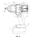
- the power PCB 138 includes the FETs 124 , which are connected to and controlled by the motor control unit 130 of the control PCB 136 . As discussed above, the FETs 124 are also electrically coupled to the power source 122 and the motor 126 . In some embodiments, the FETs 124 are directly coupled (i.e., directly physically and/or thermally coupled) to the heat sink 154 (e.g., directly on the heat sink, via copper tracings on the power PCB 138 , etc.). In other embodiments, the FETs 124 are not directly coupled to the heat sink 154 , but are in a heat transfer relationship with the heat sink 154 .
- the forward/reverse PCB 140 includes a forward/reverse switch that is operated by the forward/reverse selector 110 , which has three positions: forward, reverse, and neutral. The positions may be shifted between by moving the forward/reverse selector/shuttle 110 in a direction normal to the plane of the drawing of FIG. 1 (i.e., in/out of the page). When the forward/reverse selector 110 is shifted between these three positions, the selector 110 switches the forward/reverse switch of the forward/reverse PCB 140 , which provides a signal to the motor control unit 130 . When the trigger 112 is depressed, the motor control unit 130 causes the motor 126 to rotate clockwise, rotate counterclockwise, or not rotate (e.g., in neutral) based on the position of the selector 110 .
- the Hall sensor PCB 142 includes hall sensors 128 to detect one or more of the rotational position, velocity, and acceleration of the motor 126 .
- the Hall sensor PCB 142 is electrically coupled to the control PCB 136 to provide the outputs of the Hall sensors 128 .
- the Hall sensor PCB 142 includes a through-hole 156 through which a motor shaft/spindle 158 passes.
- Each Hall sensor 128 outputs a pulse when magnet of the rotor rotates across the face of that Hall sensor 128 .
- the motor control unit 130 can determine the position, velocity, and acceleration of the rotor.
- the motor control unit 130 uses the motor feedback information to control the FETs 124 .
- the light-emitting element (LED) PCB 144 includes the light 116 , which may be a light emitting diode (LED).
- the LED PCB 144 is electrically coupled to the control PCB 136 such that the motor control unit 130 is operable to selectively enable and disable the light 116 .
- the motor control unit 130 may enable the light 116 when the trigger 112 is depressed and/or when a separate light switch on the housing 102 is activated by the user to selectively enable/disable the light 116 independent of the trigger 112 .
- the motor control unit 130 may further include a delay timer such that the light 116 remains illuminated for a period of time after the trigger 112 or light switch is depressed or released.
- the motor control unit 130 is implemented by the control PCB 136 , which includes motor control unit 130 includes combinations of hardware and software that control operation of the power tool 100 .
- the control PCB 136 includes, among other things, a processing unit (e.g., a microprocessor, a microcontroller, or another suitable programmable device), a memory, input units, and output units.
- the processing unit includes, among other things, a control unit, an arithmetic logic unit (“ALU”), and a plurality of registers, and is implemented using a known computer architecture, such as a modified Harvard architecture, a von Neumann architecture, etc.
- ALU arithmetic logic unit
- control PCB 136 The processing unit, the memory, the input units, and the output units, as well as the various modules connected to or part of the control PCB 136 are connected by one or more control and/or data buses.
- control PCB 136 is implemented partially or entirely on a semiconductor (e.g., a field-programmable gate array [“FPGA”] semiconductor) chip, such as a chip developed through a register transfer level (“RTL”) design process.
- a semiconductor e.g., a field-programmable gate array [“FPGA”] semiconductor
- RTL register transfer level
- the memory of the control PCB 136 includes, for example, a program storage area and a data storage area.
- the program storage area and the data storage area can include combinations of different types of memory, such as read-only memory (“ROM”), random access memory (“RAM”) (e.g., dynamic RAM [“DRAM”], synchronous DRAM [“SDRAM”], etc.), electrically erasable programmable read-only memory (“EEPROM”), flash memory, a hard disk, an SD card, or other suitable magnetic, optical, physical, or electronic memory devices.
- ROM read-only memory
- RAM random access memory
- EEPROM electrically erasable programmable read-only memory
- flash memory e.g., a hard disk, an SD card, or other suitable magnetic, optical, physical, or electronic memory devices.
- the processing unit is connected to the memory and executes software instructions that are capable of being stored in a RAM of the memory (e.g., during execution), a ROM of the memory (e.g., on a generally permanent basis), or another non-transitory computer readable medium such as another memory or a disc.
- Software included in the implementation of the battery pack can be stored in the memory of the controller.
- the software includes, for example, firmware, one or more applications, program data, filters, rules, one or more program modules, and other executable instructions.
- the processing unit is configured to retrieve from memory and execute, among other things, instructions related to the control of the battery pack described herein.
- the processing unit can also store various battery pack parameters and characteristics (including battery pack nominal voltage, chemistry, battery cell characteristics, maximum allowed discharge current, maximum allowed temperature, etc.).
- the control PCB 136 includes additional, fewer, or different components.
- the motor control unit 130 may further be in communication with one or more sensors to monitor temperature, voltage, current, etc., of the power tool 100 and an attached battery pack.
- the motor control unit 130 may also include protection capabilities based on a variety of preset or calculated fault condition values related to temperatures, currents, voltages, etc., associated with the operation of the hand-held power tool.
- the various interconnections of the power tool 100 between the control PCB 136 , the power PCB 138 , the forward/reverse PCB 140 , the Hall sensor PCB 142 , and the light-emitting element (LED) PCB 144 can lead to a complex and space-consuming wiring layout within the housing 102 .
- FIGS. 6-7 illustrate a brushless power tool 200 , which has similarities to power tool 100 , but has a different electronics layout.
- the layout of power tool 200 has reduced wiring and assembly complexity relative to the power tool 100 . Additionally, the more compact and efficient layout of the power tool 200 enables additional flexibility in design, such as by allowing different handle and body dimensions and shapes. Elements of the power tool 200 similar to those of the power tool 100 are similarly numbered to simplify the description thereof.
- the power tool 200 includes a combined surfboard PCB 202 incorporating the functionality of each.
- the combined surfboard PCB 202 includes the FETs 124 of the power PCB 138 , the light 116 of the LED PCB 144 , the motor control unit 130 of the control PCB 136 , and a forward/reverse switch 203 of the forward/reverse PCB 140 (see FIG. 8C ). Accordingly, in place of wires running through the housing 102 to interconnect the various PCBs, the connections are made via conductors on the combined surfboard PCB 202 .
- the combined surfboard PCB 202 has an elongated shape, with a length more than twice its width.
- the combined surfboard PCB 202 has a rear portion adjacent to the motor 126 and a front portion adjacent to a trigger 112 .
- the Hall sensor PCB 142 is positioned above and generally perpendicularly (i.e., within 15 degrees of a perpendicular) to the combined surfboard PCB 202 ).
- the combined surfboard PCB 202 is positioned near the fan 149 , such that cooling air flow 204 passes over the FETs 124 and other components of the combined surfboard PCB 202 .
- the fan 149 operates to draw the cooling air flow 204 from the combined surfboard PCB 202 towards the fan 149 , or, as illustrated, to push the cooling air flow 204 from the fan 149 over the combined surfboard PCB 202 .
- air inlets and outlets are formed on the housing 102 to provide an inlet and outlet path for the cooling air flow 204 .
- the components of the combined surfboard PCB 202 are exposed.
- the combined surfboard PCB 202 is not encapsulated or potted within the housing 102 and is not protected against fluid within the housing 102 from reaching the FETs 124 or motor control unit 130 .
- Exposing the combined surfboard PCB 202 improves the thermal management of the components thereon.
- the cooling air flow 204 is operable to reach and cool the FETs 124 , enabling the FETs 124 to operate at higher current levels and the motor 126 to operate at higher power levels and generate higher torque for longer periods of time.
- the FETs 124 are mounted in a generally flat orientation on the combined surfboard PCB 202 .
- the FETs 124 of the power tool 100 are mounted on the power PCB 138 in a perpendicular orientation.
- the combined surfboard PCB 202 also has mounted thereon a heat sink 206 on a side opposite of the FETs 124 to provide cooling of the FETs 124 .
- the heat sink 206 is thermally coupled to the FETs 124 and includes heat sink fins 208 to improve the heat sinking capabilities of the heat sink 206 .
- one or more additional heat sinks are positioned on the same side as the FETs 124 , such that the FETs 124 and the combined surfboard PCB 202 are located between the heat sink 206 and the one or more additional heat sinks.
- the one or more additional heat sinks are thermally coupled to the FETs 124 to provide additional thermal management.
- a front portion 209 of the bottom surface of the combined surfboard PCB 202 includes the light 116 and the forward/reverse switch 203 mounted thereon.
- the FETs 124 are mounted on a rear portion 210 of the bottom surface of the combined surfboard PCB 202 .
- the heat sink 206 is mounted on the rear portion 210 of the top surface of the combined surfboard PCB 202 .
- the Hall sensor PCB 142 is above the surfboard PCB 202 and, taken together, generally form an upside-down “T” shape.
- the combined surfboard PCB 202 is centrally located within the power tool 200 above the trigger 112 , but below the motor 126 and drive mechanism 148 .
- FIG. 7 illustrates a region 211 considered above the trigger 112 and below the motor 126 .
- “Below the motor” does not require that the combined surfboard PCB 202 be directly below the motor 126 , but, rather, below a line extending parallel to the bottom surface of the motor 126 .
- a shortened combined surfboard PCB 202 that does not extend rearward in the tool 200 such that it is, in part, directly under the motor 126 as shown in FIG. 7 can still be considered “below the motor.”
- “above the trigger” does not require that the combined surfboard PCB 202 be directly above the trigger, but, rather, within the region 211 .
- the central location allows relatively short wire connections between several components of the power tool 200 .
- the exposed, unencapsulated nature of the combined surfboard PCB 202 further enables more flexibility in connection points to components thereon. That is, wires can reach components of the combined surfboard PCB 202 generally directly, rather than through limited ingress/egress ports of an encapsulation housing, allowing shorter and more direct wire connections.
- the combined surfboard PCB 202 is near the Hall sensor PCB 142 , the light 116 , the trigger 112 , the forward/reverse switch 203 , and terminals of the motor 126 .
- FIG. 8A illustrates the short wires 212 connecting the Hall sensor PCB 142 and the combined surfboard PCB 202 .
- the wires 212 may be flexible or rigid and are connected generally at a middle portion of the combined surfboard PCB 202 . Additionally, as shown, the wires 212 have a length less than a diameter of the motor 126 , less than one-fourth of the length of the combined surfboard PCB 202 , and less than a diameter of the Hall sensor PCB 142 . Although a top surface of the combined surfboard PCB 202 is substantially parallel to the longitudinal axis of the motor shaft 158 , the combined surfboard PCB 202 is angled slightly downward with respect to the motor shaft 158 from the motor side to the output side of the power tool 200 . As illustrated in FIG. 6-7 , the combined surfboard PCB 202 has a slight downward angle of less than 5 degrees with respect to the motor shaft 158 .
- the forward/reverse selector 110 includes a magnet mounted therein and the combined surfboard PCB 202 includes a forward/reverse Hall sensor (not shown) in place of the forward/reverse switch 203 .
- the forward/reverse Hall sensor detects movement of the embedded magnet when the forward/reverse selector 110 is moved, and a signal indicating the position or movement of the forward/reverse selector 110 is provided to the motor control unit 130 .
- the combined surfboard PCB 202 includes an exemplary component layout.
- various components such as one or more of the FETs 124 , are mounted on a different portion of the combined surfboard PCB 202 (e.g., top instead of bottom surface, front instead of rear portion, etc.).
- the power tool 200 is a (non-hammer) drill/driver power tool that includes a similar electronics layout, housing, motor, etc., but includes a different drive mechanism 148 having no hammer mechanism.
- FIGS. 9-11 illustrate a brushless impact wrench power tool 250 including an impact output unit 252 .
- the impact wrench is another type of hand-held power tool used for generating rotational output, but includes an impact mechanism 254 that differs from the hammer-style drive mechanism 148 of the power tools 100 and 200 .
- the power tool 250 includes a similar layout as the power tool 200 . More particularly, the power tool 250 includes a housing 256 with a handle portion 258 and motor housing portion 260 .
- the motor housing portion 260 houses a motor 126 and is positioned above the handle portion 258 .
- the handle portion 258 includes the battery interface 114 for coupling to a battery pack.
- the power tool 250 includes the combined surfboard PCB 202 and Hall sensor PCB 142 .
- the layout of power tool 250 has reduced wiring and assembly complexity relative to the power tool 100 . Additionally, the more compact and efficient layout of the power tool 250 enables additional flexibility in design, such as by allowing different handle and body dimensions and shapes. Elements of the power tool 250 similar to those of the power tools 100 and 250 are similarly numbered to simplify the description thereof.
- FIGS. 12-14 illustrate a brushless impact driver power tool 270 including an impact output unit 272 .
- the impact driver power tool 270 is another type of hand-held power tool used for generating rotational output that includes an impact mechanism 274 similar to the impact mechanism 254 .
- the power tool 270 includes a clip 276 for hanging the power tool 270 on various items, such as on a hook or tool belt.
- the power tool 270 includes a similar layout as the power tools 200 and 250 . More particularly, the power tool 270 includes a housing 278 with a handle portion 280 and motor housing portion 282 . The motor portion 282 houses a motor 126 and is positioned above the handle portion 280 . The handle portion 280 includes the battery interface 114 for coupling to a battery pack. Additionally, the power tool 270 includes the combined surfboard PCB 202 and Hall sensor PCB 142 . The layout of power tool 270 has reduced wiring and assembly complexity relative to the power tool 100 . Additionally, the more compact and efficient layout of the power tool 270 enables additional flexibility in design, such as by allowing different handle and body dimensions and shapes. Elements of the power tool 270 similar to those of the power tools 100 and 270 are similarly numbered to simplify the description thereof.
- the physical layout of the combined surfboard PCB 202 may be generally similar for each of the power tools 200 , 250 , and 270 , the particular software and hardware of the motor control unit 130 and ratings of electrical components and FETs 124 may vary and be optimized for each tool.
- FIG. 15 illustrates another brushless impact wrench power tool 300 including the impact output unit 252 and impact mechanism 254 , and having a battery pack 301 attached to the battery interface 114 .
- Elements of the power tool 300 similar to the previously described power tools are similarly numbered to simplify the description thereof.
- the layout of power tool 300 has reduced wiring complexity and reduced costs relative to the power tool 100 .
- the power tool 300 has a different PCB layout in that the combined surfboard PCB 202 is not included. Rather, the components of the combined surfboard PCB 202 are positioned on (generally) doughnut-shaped PCBs near the motor. Separate PCBs similar to the LED PCB 144 and forward/reverse PCB 140 may be provided in the power tool 300 for inclusion and support of the light 116 and switch 203 , respectively.
- the power tool 300 includes a Hall and FET PCB 302 and a control PCB 304 stacked on the motor 126 and having a hole through which the motor shaft 158 passes.
- the Hall and FET PCB 302 is kept separated from the control PCB 304 by spacers 305 .
- the Hall and FET PCB 302 includes the Hall sensors 128 and the FETs 124
- the control PCB 304 includes the motor control unit 130 .
- a heat sink 306 also with a generally doughnut or ring shape, is secured between the Hall and FET PCB 302 and the motor 126 .
- the heat sink 306 is generally used to transfer heat away from the FETs 124 .
- FIGS. 17A-B illustrate the Hall and FET PCB 302 in greater detail.
- the Hall and FET PCB 302 has a generally circular shape with a through-hole 308 in the center.
- a motor shaft 158 as well as a motor bushing 309 (see, e.g., FIG. 21 ), pass through the through-hole 308 .
- the Hall and FET PCB 302 has two generally flat mounting surfaces: a first face 310 (see FIG. 17A ) and a second face 312 (see FIG. 17B ).
- the FETs 124 are mounted on the Hall and FET PCB 302 in a flat orientation.
- the control PCB 304 has a through-hole 314 and two generally flat mounting surfaces: a first face 316 (see FIG.
- the control PCB 304 further includes control PCB mounting holes 319 .
- the control PCB 304 and Hall and FET PCB 302 are located coaxially about the motor shaft 158 and the faces 310 , 312 , 316 , and 318 are generally parallel to each other.
- the PCBs 302 and 304 are secured to an end of the motor 126 . By locating FETs 124 with Hall sensors 128 on a single Hall and FET PCB 302 secured to the end of the motor 126 , the Hall and FET PCB 302 is able to receive a large amount of air flow 204 for cooling in addition to reducing the internal wiring of the power tool 300 .
- the Hall and FET PCB 302 further includes Hall and FET PCB mounting holes 320 , motor lead pads 322 , and copper bus bars 324 .
- the copper bus bars 324 allow for additional space on the Hall and FET PCB 302 to be used for other features such as high current traces. Accordingly, rather than occupying space on the Hall and FET PCB 302 , the copper bus bars 324 jump above the Hall and FET PCB 302 . In alternative embodiments, traces on the Hall and FET PCB 302 are used instead of the copper bus bars 324 .
- the Hall and FET PCB mounting holes 320 allow metal standoffs 305 (see FIG. 16A-B ) of the heat sink 306 to pass through the Hall and FET PCB 302 .
- the metal standoffs 305 provide spacing between the PCBs 302 and 304 and allow the control PCB 304 to be attached to the heat sink 306 .
- the metal standoffs 305 receive control PCB mounting screws inserted through mounting holes 319 of the control PCB 304 to secure the control PCB 304 to the heat sink 306 .
- the control PCB mounting screws secure both the control PCB 304 and the Hall and FET PCB 302 to the heat sink 306 .
- Hall and FET PCB mounting holes 320 may be used for both allowing metal standoffs 305 of the heat sink 306 to pass through the Hall and FET PCB 302 and for securing the Hall and FET PCB 302 to the heat sink 306 . Tightly securing the Hall and FET PCB 302 to the heat sink 306 allows for heat to dissipate from the Hall and FET PCB 302 to the heat sink 306 more easily and minimizes vibration between the Hall and FET PCB 302 and the motor 126 .
- the number of mounting holes 319 and 320 and their location on the PCBs 302 and 304 are varied.
- the general shape of the PCBs 302 and 304 is varied.
- FIGS. 19A-G illustrate a process for attaching the motor 126 , Hall and FET PCB 302 , and heat sink 306 together.
- FIG. 19A illustrates a motor stator 330 of the motor 126 with plastic end caps 332 and 334 at each end of the motor stator 330 , respectively, and six motor leads 336 that are stripped down to the plastic end cap 334 . Wire support features 338 are part of the plastic end cap 334 and will be used to properly guide the motor leads 336 , as explained below.
- FIG. 19B illustrates the heat sink 306 placed on the plastic end cap 334 of the motor stator 330 .
- the metal standoffs 305 of the heat sink 306 may be used for mounting the control PCB 304 and/or locating the Hall and FET PCB 302 in some embodiments.
- FIG. 19C illustrates the heat sink 306 fastened to the motor stator 330 using heat sink mounting screws 340 .
- Heat sink mounting clips 342 are attached to an end of the motor stator 330 opposite the end where the heat sink 306 is attached.
- the heat sink mounting screws 340 are threadingly engaged with heat sink mounting standoffs of the heat sink 306 and the heat sink mounting clips 342 to secure the heat sink 306 to the motor stator 330 .
- the number and location of heat sink mounting elements are varied.
- the motor leads 336 are then bent downward to fit within the wire support features 338 as shown in FIG. 19D . Wrapping the motor leads 336 around the wire support features 338 relieves strain on the motor leads 336 before they are soldered to the Hall and FET PCB 302 . In some embodiments, glue can also be applied to the motor leads 336 to secure them to the heat sink 306 .
- FIG. 19E illustrates a heat sink pad 344 placed on top of the heat sink 306 .
- the heat sink pad 344 is a thin, electrical insulator with high thermal conductivity. These characteristics allow the heat sink pad 306 to electrically isolate the metal heat sink 306 from the Hall and FET PCB 302 while still allowing heat from the Hall and FET PCB 302 to dissipate via the heat sink 306 .
- FIG. 19F illustrates the Hall and FET PCB 302 placed on top of the heat sink pad 344 and heat sink 306 .
- the motor leads 336 align with the openings of the motor lead pads 322 , and the metal standoffs 305 of the heat sink 306 pass through the Hall and FET PCB mounting holes 320 .
- downward force is applied to the Hall and FET PCB 302 .
- the motor leads 336 are soldered to the motor lead pads 322 to create solder joints 345 , which not only electrically connect the motor leads 336 to the Hall and FET PCB 302 , but also mechanically attach the two components together.
- the motor leads 336 are cut near the motor lead pads 322 .
- the Hall and FET PCB 302 can be secured to the heat sink 306 (which is secured to the motor 126 ) using Hall and FET PCB mounting screws.
- control PCB 304 is then secured to the heat sink 306 with the Hall and FET PCB 302 positioned between the heat sink 306 and the control PCB 304 .
- the control PCB 304 is secured to the heat sink 306 using control PCB mounting screws received by the standoffs 305 .
- FIG. 20 illustrates the end of the motor stator 330 opposite from the end having the Hall and FET PCB 302 .
- This view of the motor stator 330 illustrates a wire crossover design, which wraps a wire behind the plastic end cap 332 . Wrapping the wires of the motor stator 330 around the plastic end cap 332 allows them to travel 180 degrees from one pole to the opposite pole of the motor stator 330 in an efficient manner.
- the wrapped wires 346 are on top of a ledge portion 348 , which wraps around the motor stator 330 , and are radially outside of tab portions 349 that extend up from the ledge portion 348 . As illustrated, at no point are three wires located at the same circumferential position and stacked along the ledge portion 348 . Rather, at most, two wires are stacked, allowing a reduced height of the tab portions 349 and overall length of the motor stator 330 .
- control PCB 304 is not located adjacent to the Hall and FET PCB 302 about the motor shaft 158 , and the metal standoffs 305 do not pass through the Hall and FET PCB 302 . Rather, the length of the metal standoffs 305 is reduced such that they terminate at the surface of the Hall and FET PCB 302 . The reduced metal standoffs 305 , which no longer provide spacing functionality, then receive Hall and FET PCB mounting screws to secure the Hall and FET PCB 302 to the heat sink 306 and motor 126 combination, as shown in FIG. 21 .
- control PCB 304 may be referred to as the control PCB 304 a .
- the control PCB 304 a may be located in several locations within the power tool 300 .
- the Hall and FET PCB 302 is coupled to the control PCB 304 a via cable connector 350 and a ribbon cable (not shown).
- FIGS. 22A-C illustrate exemplary locations within the power tool 300 that the control PCB 304 a may be positioned.
- the control PCB 304 a is located in the handle portion 258 of the power tool 300 .
- the control PCB 304 a is located above the trigger 112 and handle portion 258 , but below the motor 126 and impact mechanism 254 .
- the control PCB 304 a is located below the handle portion 258 and above the battery interface 114 .
- FIGS. 15-22 are described with respect to an impact wrench power tool 300 , the various layout and motor assembly described may be implemented in other types of power tools, such as a non-hammer drill/driver power tool, a hammer drill/driver power tool (see, e.g., FIGS. 1-9 ) and an impact driver power tool (see, e.g., FIGS. 12-14 ).
- a non-hammer drill/driver power tool a hammer drill/driver power tool
- a hammer drill/driver power tool see, e.g., FIGS. 1-9
- an impact driver power tool see, e.g., FIGS. 12-14 .
- the above power tools are described as cordless, battery-powered tools.
- the battery packs, such as battery pack 301 used to power these power tools may be, for instance, 18 volt lithium ion type battery packs, although battery packs with other battery chemistries, shapes, voltage levels, etc. may be used in other embodiments.
- these power tools are corded, AC-powered tools.
- the power tools include an AC power cord coupled to a transformer block to condition and transform the AC power for use by the components of the power tools.
- These AC-powered tools may also include one of the above-described layouts including one of the combined surfboard PCB layouts and doughnut PCB layouts.
- the invention provides, among other things, a layout design and assembly of brushless power tools.
- Various features and advantages of the invention are set forth in the following claims.
Abstract
Description
Claims (20)
Priority Applications (10)
| Application Number | Priority Date | Filing Date | Title |
|---|---|---|---|
| US13/841,246 US9450471B2 (en) | 2012-05-24 | 2013-03-15 | Brushless DC motor power tool with combined PCB design |
| CN201390000513.1U CN204658374U (en) | 2012-08-20 | 2013-08-19 | There is the brushless direct current motor electric tool of integrated printed circuit board design |
| AU2013306054A AU2013306054B2 (en) | 2012-08-20 | 2013-08-19 | Brushless DC motor power tool with combined PCB design |
| PCT/US2013/055587 WO2014031539A1 (en) | 2012-08-20 | 2013-08-19 | Brushless dc motor power tool with combined pcb design |
| US15/241,475 US9960656B2 (en) | 2012-05-24 | 2016-08-19 | Brushless DC motor power tool with combined PCB design |
| US15/601,002 US9774229B1 (en) | 2012-05-24 | 2017-05-22 | Brushless DC motor power tool with combined PCB design |
| US15/816,221 US9954417B2 (en) | 2012-05-24 | 2017-11-17 | Brushless DC motor power tool with combined PCB design |
| US15/966,443 US11031843B2 (en) | 2012-05-24 | 2018-04-30 | Brushless DC motor power tool with combined PCB design |
| US16/388,422 US10530220B2 (en) | 2012-05-24 | 2019-04-18 | Brushless DC motor power tool with combined PCB design |
| US17/341,631 US11923752B2 (en) | 2012-05-24 | 2021-06-08 | Brushless DC motor power tool with combined PCB design |
Applications Claiming Priority (3)
| Application Number | Priority Date | Filing Date | Title |
|---|---|---|---|
| US201261651137P | 2012-05-24 | 2012-05-24 | |
| US201261684982P | 2012-08-20 | 2012-08-20 | |
| US13/841,246 US9450471B2 (en) | 2012-05-24 | 2013-03-15 | Brushless DC motor power tool with combined PCB design |
Related Child Applications (1)
| Application Number | Title | Priority Date | Filing Date |
|---|---|---|---|
| US15/241,475 Continuation US9960656B2 (en) | 2012-05-24 | 2016-08-19 | Brushless DC motor power tool with combined PCB design |
Publications (2)
| Publication Number | Publication Date |
|---|---|
| US20130313925A1 US20130313925A1 (en) | 2013-11-28 |
| US9450471B2 true US9450471B2 (en) | 2016-09-20 |
Family
ID=49621043
Family Applications (7)
| Application Number | Title | Priority Date | Filing Date |
|---|---|---|---|
| US13/841,246 Active 2034-08-15 US9450471B2 (en) | 2012-05-24 | 2013-03-15 | Brushless DC motor power tool with combined PCB design |
| US15/241,475 Active US9960656B2 (en) | 2012-05-24 | 2016-08-19 | Brushless DC motor power tool with combined PCB design |
| US15/601,002 Active US9774229B1 (en) | 2012-05-24 | 2017-05-22 | Brushless DC motor power tool with combined PCB design |
| US15/816,221 Active US9954417B2 (en) | 2012-05-24 | 2017-11-17 | Brushless DC motor power tool with combined PCB design |
| US15/966,443 Active US11031843B2 (en) | 2012-05-24 | 2018-04-30 | Brushless DC motor power tool with combined PCB design |
| US16/388,422 Active US10530220B2 (en) | 2012-05-24 | 2019-04-18 | Brushless DC motor power tool with combined PCB design |
| US17/341,631 Active 2033-10-13 US11923752B2 (en) | 2012-05-24 | 2021-06-08 | Brushless DC motor power tool with combined PCB design |
Family Applications After (6)
| Application Number | Title | Priority Date | Filing Date |
|---|---|---|---|
| US15/241,475 Active US9960656B2 (en) | 2012-05-24 | 2016-08-19 | Brushless DC motor power tool with combined PCB design |
| US15/601,002 Active US9774229B1 (en) | 2012-05-24 | 2017-05-22 | Brushless DC motor power tool with combined PCB design |
| US15/816,221 Active US9954417B2 (en) | 2012-05-24 | 2017-11-17 | Brushless DC motor power tool with combined PCB design |
| US15/966,443 Active US11031843B2 (en) | 2012-05-24 | 2018-04-30 | Brushless DC motor power tool with combined PCB design |
| US16/388,422 Active US10530220B2 (en) | 2012-05-24 | 2019-04-18 | Brushless DC motor power tool with combined PCB design |
| US17/341,631 Active 2033-10-13 US11923752B2 (en) | 2012-05-24 | 2021-06-08 | Brushless DC motor power tool with combined PCB design |
Country Status (1)
| Country | Link |
|---|---|
| US (7) | US9450471B2 (en) |
Cited By (14)
| Publication number | Priority date | Publication date | Assignee | Title |
|---|---|---|---|---|
| US20150340921A1 (en) * | 2014-05-26 | 2015-11-26 | Makita Corporation | Electric power tool |
| US20170288499A1 (en) * | 2016-03-30 | 2017-10-05 | Milwaukee Electric Tool Corporation | Brushless motor for a power tool |
| US20190006909A1 (en) * | 2017-07-03 | 2019-01-03 | Makita Corporation | Power tool |
| US10348159B2 (en) | 2013-06-06 | 2019-07-09 | Milwaukee Electric Tool Corporation | Brushless DC motor configuration for a power tool |
| US20190275658A1 (en) * | 2018-03-09 | 2019-09-12 | Snap-On Incorporated | Handle Support Module |
| US10840776B2 (en) | 2017-05-27 | 2020-11-17 | Actuator Electric Motors | Self-contained brushless motor and brushless controller |
| US10848042B2 (en) | 2017-02-13 | 2020-11-24 | Milwaukee Electric Tool Corporation | Brushless direct current motor for power tools |
| US10848034B2 (en) | 2016-09-19 | 2020-11-24 | Black & Decker Inc. | Control and power module for brushless motor |
| US10998797B2 (en) | 2017-12-19 | 2021-05-04 | Tti (Macao Commercial Offshore) Limited | Electric motor assembly including end cap having heat sink for heat-generating electrical component |
| US11477889B2 (en) | 2018-06-28 | 2022-10-18 | Black & Decker Inc. | Electronic switch module with an integrated flyback diode |
| USD968473S1 (en) * | 2021-08-31 | 2022-11-01 | Bo Wu | Portable handheld air compressor |
| US11515743B2 (en) | 2018-11-29 | 2022-11-29 | Milwaukee Electric Tool Corporation | Motor winding design for an electric motor |
| US11890741B2 (en) | 2019-05-13 | 2024-02-06 | Milwaukee Electric Tool Corporation | Contactless trigger with rotational magnetic sensor for a power tool |
| US11949295B2 (en) | 2020-04-21 | 2024-04-02 | Milwaukee Electric Tool Corporation | Power tool printed circuit board including embedded busbars |
Families Citing this family (60)
| Publication number | Priority date | Publication date | Assignee | Title |
|---|---|---|---|---|
| JP5512110B2 (en) | 2008-09-26 | 2014-06-04 | 株式会社マキタ | Electric tool |
| US20140232326A1 (en) * | 2010-04-07 | 2014-08-21 | Black & Decker Inc. | Battery pack and charger platform for power tool systems including battery pack identification scheme |
| EP2580847B1 (en) * | 2010-06-14 | 2021-11-17 | Black & Decker Inc. | Rotor assembly for brushless motor for a power tool |
| WO2013063507A1 (en) | 2011-10-26 | 2013-05-02 | Milwaukee Electric Tool Corporation | Wireless tracking of power tools and related devices |
| CA2941582C (en) * | 2012-01-06 | 2020-04-07 | Sears Brands, Llc | Programmable portable power tool with brushless dc motor |
| US9450471B2 (en) | 2012-05-24 | 2016-09-20 | Milwaukee Electric Tool Corporation | Brushless DC motor power tool with combined PCB design |
| DE102012217906A1 (en) * | 2012-10-01 | 2014-04-03 | Robert Bosch Gmbh | Hand tool with a designed to provide a predetermined maximum engine power drive motor |
| JP6084523B2 (en) * | 2013-06-25 | 2017-02-22 | 株式会社マキタ | Charger |
| EP2929986B1 (en) * | 2014-03-28 | 2017-09-13 | Black & Decker Inc. | Biasing member for a power tool forward/reverse actuator |
| WO2016031719A1 (en) * | 2014-08-29 | 2016-03-03 | 日立工機株式会社 | Electric working machine |
| JP6402777B2 (en) * | 2014-10-31 | 2018-10-10 | 工機ホールディングス株式会社 | Electric working machine |
| US10236742B2 (en) * | 2014-11-25 | 2019-03-19 | Black & Decker Inc. | Brushless motor for a power tool |
| CN208195813U (en) | 2015-02-25 | 2018-12-07 | 米沃奇电动工具公司 | Mitre saw |
| US10369642B2 (en) | 2015-03-12 | 2019-08-06 | Robert Bosch Tool Corporation | Power tool with protected circuit board orientation |
| US11260517B2 (en) | 2015-06-05 | 2022-03-01 | Ingersoll-Rand Industrial U.S., Inc. | Power tool housings |
| WO2016196979A1 (en) | 2015-06-05 | 2016-12-08 | Ingersoll-Rand Company | Impact tools with ring gear alignment features |
| EP3302891B1 (en) * | 2015-06-05 | 2020-11-04 | Ingersoll-Rand Industrial U.S., Inc. | Power tool user interfaces |
| CN110712163B (en) | 2015-06-05 | 2021-09-24 | 英格索兰工业美国公司 | Lighting system for power tool |
| US11491616B2 (en) | 2015-06-05 | 2022-11-08 | Ingersoll-Rand Industrial U.S., Inc. | Power tools with user-selectable operational modes |
| US10418879B2 (en) | 2015-06-05 | 2019-09-17 | Ingersoll-Rand Company | Power tool user interfaces |
| US10615670B2 (en) | 2015-06-05 | 2020-04-07 | Ingersoll-Rand Industrial U.S., Inc. | Power tool user interfaces |
| US10128723B2 (en) * | 2015-07-07 | 2018-11-13 | Milwaukee Electric Tool Corporation | Printed circuit board spacer |
| US20170014984A1 (en) * | 2015-07-16 | 2017-01-19 | Apex Brands, Inc. | High-power lightweight tool |
| US10786894B2 (en) * | 2015-10-14 | 2020-09-29 | Black & Decker Inc. | Brushless motor system for power tools |
| EP3162513B1 (en) * | 2015-10-30 | 2019-04-17 | Black & Decker Inc. | High power brushless motor |
| EP3377272B1 (en) | 2015-11-20 | 2020-11-18 | TTI (Macao Commercial Offshore) Limited | Power tools with integrated circuit boards |
| JP2017094453A (en) * | 2015-11-25 | 2017-06-01 | パナソニックIpマネジメント株式会社 | Electric tool |
| DE102016003150A1 (en) * | 2016-03-16 | 2017-09-21 | Andreas Stihl Ag & Co. Kg | Hand-operated implement with an electric motor |
| EP3436220B1 (en) * | 2016-03-31 | 2023-11-22 | Milwaukee Electric Tool Corporation | System for cooling a power tool |
| WO2018038370A1 (en) * | 2016-08-25 | 2018-03-01 | 엘지전자 주식회사 | Vacuum |
| JP6964230B2 (en) * | 2017-03-17 | 2021-11-10 | パナソニックIpマネジメント株式会社 | Circuit board and lighting equipment |
| AU2017405808A1 (en) | 2017-03-24 | 2019-10-10 | Tti (Macao Commercial Offshore) Limited | Power tools with integrated circuit boards |
| JP6677917B2 (en) * | 2017-03-31 | 2020-04-08 | 工機ホールディングス株式会社 | Electric tool |
| US10541588B2 (en) | 2017-05-24 | 2020-01-21 | Black & Decker Inc. | Electronic power module for a power tool having an integrated heat sink |
| CN212947621U (en) | 2017-08-07 | 2021-04-13 | 米沃奇电动工具公司 | Electric tool and electric tool device |
| CN109510530B (en) | 2017-09-15 | 2021-03-02 | 德丰电创科技股份有限公司 | Electrical switching unit for controlling the operation of a DC motor of an electrical apparatus |
| WO2019108621A1 (en) | 2017-11-29 | 2019-06-06 | Milwaukee Electric Tool Corporation | Externally attachable tracking module for a power tool |
| CN108258873B (en) * | 2017-12-15 | 2020-02-21 | 浙江明磊工具实业有限公司 | Inductive brushless motor |
| US20190217459A1 (en) * | 2018-01-16 | 2019-07-18 | Tti (Macao Commercial Offshore) Limited | Operational data distribution in a power tool |
| US11817749B2 (en) | 2018-04-27 | 2023-11-14 | Koki Holdings Co., Ltd. | Power tool |
| DE102018110754A1 (en) * | 2018-05-04 | 2019-11-07 | C. & E. Fein Gmbh | electronics unit |
| TWI676348B (en) * | 2018-05-25 | 2019-11-01 | 車王電子股份有限公司 | electrical tools |
| JP7083298B2 (en) * | 2018-09-28 | 2022-06-10 | 本田技研工業株式会社 | Motor structure and vehicle |
| TWI758581B (en) | 2019-01-30 | 2022-03-21 | 車王電子股份有限公司 | electrical tools |
| WO2020163450A1 (en) | 2019-02-06 | 2020-08-13 | Milwaukee Electric Tool Corporation | Power tool with shared terminal block |
| DE102019203525A1 (en) * | 2019-03-15 | 2020-09-17 | Brose Fahrzeugteile SE & Co. Kommanditgesellschaft, Würzburg | Drive device with a brushless electric motor |
| US20210178567A1 (en) * | 2019-06-24 | 2021-06-17 | Milwaukee Electric Tool Corporation | Power tools with high-emissivity heat sinks |
| CN114223023A (en) | 2019-08-13 | 2022-03-22 | 米沃奇电动工具公司 | Wireless remote control key for controlling authentication of power tool device |
| WO2021081825A1 (en) * | 2019-10-30 | 2021-05-06 | 南京德朔实业有限公司 | Alternating current electric tool |
| CN114830844B (en) | 2019-11-21 | 2024-03-19 | 米沃奇电动工具公司 | Pluggable wireless communication device for power tool |
| JP2023505668A (en) | 2019-12-10 | 2023-02-10 | ミルウォーキー エレクトリック ツール コーポレイション | Motor Control for Gas Engine Exchanger Based on Battery Pack Configuration Data |
| WO2021134905A1 (en) * | 2019-12-30 | 2021-07-08 | 南京德朔实业有限公司 | Electric tool and electric control assembly thereof |
| CN220022577U (en) * | 2020-02-05 | 2023-11-14 | 米沃奇电动工具公司 | Power tool and electric motor assembly |
| WO2021162913A1 (en) | 2020-02-12 | 2021-08-19 | Forum Us, Inc. | Electrically driven power end apparatus and methods |
| US11658543B2 (en) | 2020-04-07 | 2023-05-23 | Milwaukee Electric Tool Corporation | Impact tool and electric motor |
| US11658545B2 (en) | 2020-06-19 | 2023-05-23 | Snap-On Incorporated | Brushless direct current motor end cap |
| US11787034B2 (en) * | 2020-11-02 | 2023-10-17 | Globe (jiangsu) Co., Ltd. | Power head and outdoor power equipment using the same |
| WO2023108051A1 (en) * | 2021-12-10 | 2023-06-15 | Milwaukee Electric Tool Corporation | Inverter including wide-bandgap semiconductor devices in a power tool |
| CN115336460A (en) * | 2022-08-30 | 2022-11-15 | 江苏东成工具科技有限公司 | Electric tool |
| CN116073557B (en) * | 2023-03-06 | 2023-09-08 | 浙江远鸿新能源科技有限公司 | Cordless electric drill motor |
Citations (102)
| Publication number | Priority date | Publication date | Assignee | Title |
|---|---|---|---|---|
| US3531702A (en) | 1968-03-05 | 1970-09-29 | Sperry Rand Corp | Logic control system for brushless d.c. motors |
| US3678358A (en) | 1970-07-14 | 1972-07-18 | Gen Electric | Brushless dc adjustable speed drive with static regenerative dc motor control |
| US3783359A (en) | 1971-12-23 | 1974-01-01 | Bendix Corp | Brushless d. c. motor using hall generators for commutation |
| DE2929259B1 (en) | 1979-07-17 | 1981-01-22 | Siemens Ag | Low voltage cable with branch sleeve and fuses |
| EP0192469A2 (en) | 1985-02-19 | 1986-08-27 | Dobson Park Industries Plc | Electric motors and power tools |
| US4619624A (en) | 1983-11-07 | 1986-10-28 | Kerr Iii Charles | Method of making improved electroluminescent panels |
| US5115175A (en) | 1988-02-03 | 1992-05-19 | Hall Surgical | Drill having alternate mode control |
| US5148349A (en) | 1990-01-08 | 1992-09-15 | Nec Corporation | Electronic part mountable on the surface of a printed circuit board and method of mounting the same |
| US5235261A (en) | 1991-06-27 | 1993-08-10 | Stryker Corporation | DC powered surgical handpiece having a motor control circuit |
| US5747953A (en) | 1996-03-29 | 1998-05-05 | Stryker Corporation | Cordless, battery operated surical tool |
| US5753173A (en) | 1993-10-25 | 1998-05-19 | Minnesota Mining And Manufacturing Company | Method of manufacturing a blood oxygenation system |
| GB2314980B (en) | 1996-07-02 | 2000-06-28 | Defond Mfg Ltd | Power tool speed controller |
| USRE36820E (en) | 1995-01-13 | 2000-08-15 | Methode Electronics, Inc. | Removable optoelectronic module |
| US6123158A (en) | 1996-08-03 | 2000-09-26 | Wacker-Werke Gmbh & Co., Kg | Electric tool with ducted cooled control electronics |
| US6320286B1 (en) | 1999-09-01 | 2001-11-20 | Ramachandran Ramarathnam | Portable electric tool |
| US6431879B2 (en) | 2000-02-10 | 2002-08-13 | Tyco Electronics Corporation | Printed circuit board connector |
| US6434013B2 (en) | 2000-02-24 | 2002-08-13 | Keihin Corporation | Electronic circuit board case |
| US20020134811A1 (en) | 2001-01-29 | 2002-09-26 | Senco Products, Inc. | Multi-mode power tool utilizing attachment |
| US6538403B2 (en) | 2000-01-07 | 2003-03-25 | Black & Decker Inc. | Brushless DC motor sensor control system and method |
| US6552904B2 (en) | 2001-08-13 | 2003-04-22 | Black & Decker Inc. | Power tool with heat sink assembly |
| US6570284B1 (en) | 2001-12-11 | 2003-05-27 | Black & Decker Inc. | Brushless motor having double insulation |
| US6577030B2 (en) | 2000-10-18 | 2003-06-10 | Mitsubishi Denki Kabushiki Kaisha | Electric power steering apparatus |
| US6585246B2 (en) | 2001-06-22 | 2003-07-01 | Delaware Capital Formation, Inc. | Electric clamp |
| JP2003199310A (en) | 2001-12-26 | 2003-07-11 | Nidec Shibaura Corp | Brushless dc motor and power tool |
| JP2003209960A (en) | 2002-01-15 | 2003-07-25 | Nidec Shibaura Corp | Power tool |
| US6644638B1 (en) | 2001-06-22 | 2003-11-11 | Delaware Capital Formation, Inc. | Electric clamp |
| US20030222516A1 (en) | 2000-01-07 | 2003-12-04 | Cleanthous Aris C. | Brushless dc motor |
| EP1374653A1 (en) | 2001-03-24 | 2004-01-02 | Marquardt GmbH | Control device for an electric motor |
| US6765317B2 (en) | 2002-04-02 | 2004-07-20 | Defond Manufacturing Limited | Power supply module for electrical power tools |
| US6791219B1 (en) | 2003-06-18 | 2004-09-14 | Bvr Technologies Company | Contactless electro-mechanical actuator with coupled electronic motor commutation and output position sensors |
| US6794594B2 (en) | 2003-01-13 | 2004-09-21 | Defond Manufacturing Limited | Power tool trigger assembly |
| US6799282B2 (en) | 2000-03-24 | 2004-09-28 | International Business Machines Corporation | Power generating mechanism that has a duct, heat pipe, or heat sink to efficiently diffuse heat generated by a heat |
| US6866105B2 (en) | 2002-09-12 | 2005-03-15 | Hilti Aktiengesellschaft | Electrical, fan-cooled tool |
| US6895750B2 (en) | 2003-02-20 | 2005-05-24 | Jidosha Denki Kogyo Co., Ltd. | Nozzle vane driving control apparatus of variable nozzle turbocharger |
| US20050121209A1 (en) | 2003-11-11 | 2005-06-09 | Matsushita Electric Works, Ltd. | Transportable power tool |
| US6920047B2 (en) | 2001-08-10 | 2005-07-19 | Black & Decker Inc. | Electrically isolated module |
| JP2005304146A (en) | 2004-04-08 | 2005-10-27 | Nidec Shibaura Corp | Motor drive |
| US7000911B2 (en) | 2001-06-22 | 2006-02-21 | Delaware Capital Formation, Inc. | Motor pack for automated machinery |
| US20060052914A1 (en) | 2004-09-09 | 2006-03-09 | Keihin Corporation | Power drive unit |
| US7046518B2 (en) | 2001-04-02 | 2006-05-16 | International Rectifier Corporation | Power module |
| US7064462B2 (en) | 2002-02-04 | 2006-06-20 | Milwaukee Electric Tool Corporation | Power tools with switched reluctance motor |
| EP1683169A1 (en) | 2003-11-07 | 2006-07-26 | Electrische Apparatenfabriek Capax B.V. | Switch unit with ventilation |
| US20060181857A1 (en) | 2005-02-16 | 2006-08-17 | Belady Christian L | Redundant power beneath circuit board |
| EP1715565A1 (en) | 2005-04-20 | 2006-10-25 | Hitachi Koki Co., Ltd. | Power tool |
| US7208943B2 (en) | 2005-06-03 | 2007-04-24 | Delphi Technologies, Inc. | Electrical device enclosure |
| US7259531B1 (en) | 2006-04-05 | 2007-08-21 | Kwang-Hwa Liu | Speed control of brushless DC motors |
| US20070228824A1 (en) | 2006-04-03 | 2007-10-04 | Hitachi, Ltd. | Electro Mechanical Brake, Control Device |
| JP2007283447A (en) | 2006-04-18 | 2007-11-01 | Makita Corp | Power tool |
| US20070267990A1 (en) | 2006-05-22 | 2007-11-22 | Black & Decker Inc. | Electronically commutated motor and control system employing phase angle control of phase current |
| US7312545B2 (en) | 2004-07-06 | 2007-12-25 | Hitachi, Ltd. | Controller for electric power steering and electric power steering system |
| EP1873800A1 (en) | 2006-06-29 | 2008-01-02 | Festool GmbH | Electrical machine tool and switch therefor |
| US20080041620A1 (en) | 2004-05-04 | 2008-02-21 | Albanese Patricia M | Surface mount attachment of components |
| US7371150B2 (en) | 2004-04-13 | 2008-05-13 | Black & Decker Inc. | Electric sander and motor control therefor |
| US7375287B2 (en) | 2002-08-28 | 2008-05-20 | Minebea Co., Ltd. | Assembly for accommodating the power electronics and control electronics of an electric motor |
| US7400106B2 (en) | 2005-11-04 | 2008-07-15 | Robert Bosch Gmbh | Method and apparatus for providing torque limit feedback in a power drill |
| US20080170841A1 (en) | 2007-01-17 | 2008-07-17 | W&H Dentalwerk Burmoos Gmbh | Medical Handle |
| WO2008083667A2 (en) | 2007-01-13 | 2008-07-17 | Marquardt Gmbh | Control device for an electric motor |
| US20080179078A1 (en) | 2006-11-22 | 2008-07-31 | Opsitos Robert J | Remote diodes in a cordless tool |
| DE102007011658A1 (en) | 2007-03-09 | 2008-09-11 | Marquardt Gmbh | Electrical switch, particularly for electrical tool, has signaling device, which has slider, which is interacting in electrically contacting manner with contact area for generating signal for starting and shutdown of electric motor |
| DE102008036393A1 (en) | 2007-08-07 | 2009-02-12 | Marquardt Gmbh | Electric switch for use in electric hand tool i.e. rechargeable and main electric tool such as drill, has slide-gate valve acting on contact system for switching in such manner that movement of operating element is deflected |
| US20090057006A1 (en) | 2007-09-05 | 2009-03-05 | Kokusan Denki Co., Ltd. | Electronic unit and production method of the same |
| US20090145621A1 (en) | 2007-12-07 | 2009-06-11 | James Ching Sik Lau | power tool |
| US7547123B2 (en) | 2005-09-26 | 2009-06-16 | Advanced Illumination, Inc. | High efficiency, compact, modular forced air cooling system for high intensity LED light source |
| US20090160468A1 (en) | 2007-12-19 | 2009-06-25 | Aehr Test Systems | System for testing an integrated circuit of a device and its method of use |
| US7564208B2 (en) | 2002-07-01 | 2009-07-21 | Xidem, Inc. | Electronically controlled electric motor |
| US20090200961A1 (en) | 2008-02-09 | 2009-08-13 | Marquardt Gmbh | Electrical device, in particular an electric power tool or an electrical appliance |
| EP2103396A1 (en) | 2007-01-18 | 2009-09-23 | Max Co., Ltd. | Machine tool having brushless motor |
| JP2009240022A (en) | 2008-03-26 | 2009-10-15 | Nidec Shibaura Corp | Motor controller, brushless motor, and power tool |
| US20090272599A1 (en) | 2006-04-11 | 2009-11-05 | Nsk Ltd. | Electric Power Steering Apparatus |
| US20090277682A1 (en) | 2008-05-07 | 2009-11-12 | Honda Motor Co., Ltd. | Protective structure for a circuit board and method for fabricating the same |
| WO2009145205A1 (en) | 2008-05-29 | 2009-12-03 | Hitachi Koki Co., Ltd. | Electric power tool |
| WO2009145206A2 (en) * | 2008-05-29 | 2009-12-03 | Hitachi Koki Co., Ltd. | Electric power tool |
| JP2009285787A (en) | 2008-05-29 | 2009-12-10 | Hitachi Koki Co Ltd | Electric power tool |
| US7638958B2 (en) | 2005-06-28 | 2009-12-29 | Stryker Corporation | Powered surgical tool with control module that contains a sensor for remotely monitoring the tool power generating unit |
| US20090322149A1 (en) | 2008-06-27 | 2009-12-31 | Kokusan Denki Co., Ltd. | Onboard electric power control device |
| US7643296B2 (en) | 2006-01-16 | 2010-01-05 | Mitsubishi Electric Corporation | Motor drive circuit and outdoor unit for air conditioner |
| US20100001675A1 (en) | 2008-07-04 | 2010-01-07 | Makita Corporation | Electric Power Tool |
| US7646155B2 (en) | 2003-04-30 | 2010-01-12 | Balck & Decker Inc. | Generic motor control system |
| DE102008041725A1 (en) | 2008-08-29 | 2010-03-04 | Robert Bosch Gmbh | Circuit, switching device and method for the currentless switching of a power circuit of a circuit |
| US7673701B2 (en) | 2006-08-31 | 2010-03-09 | Matsushita Electric Works, Ltd. | Power tool having control means for monitoring screw tightening operations |
| US20100065295A1 (en) | 2007-03-20 | 2010-03-18 | Hitachi Koki Co., Ltd. | Cordless power tool and accomodation case |
| DE102008042799A1 (en) | 2008-10-13 | 2010-04-15 | Robert Bosch Gmbh | Switch arrangement, electrical load and machine tool |
| US7703330B2 (en) | 2006-08-31 | 2010-04-27 | Matsushita Electric Works, Ltd. | Power tool |
| US20100108341A1 (en) | 2005-10-31 | 2010-05-06 | Black & Decker Inc. | Battery pack, charger and terminal block arrangements for cordless power tool system |
| US20100123359A1 (en) | 2008-11-19 | 2010-05-20 | Hitachi Koki Co., Ltd. | Power Tool |
| US7733054B2 (en) | 2005-10-31 | 2010-06-08 | Black & Decker Inc. | Thermal management systems for battery pack |
| US20100163266A1 (en) | 2008-12-26 | 2010-07-01 | Makita Corporation | Electric power tools |
| EP2050112B1 (en) | 2006-08-10 | 2010-07-14 | Marquardt GmbH | Control device, in particular in the form of an electric switch for electric hand tools |
| EP2100702B1 (en) | 2008-03-12 | 2010-09-22 | Makita Corporation | Electrical power tools |
| US20100283332A1 (en) | 2009-05-11 | 2010-11-11 | Junichi Toukairin | Electric power tool |
| US20100326804A1 (en) | 2009-06-30 | 2010-12-30 | Dietmar Saur | Hand-held power tool |
| US20100327678A1 (en) | 2009-06-24 | 2010-12-30 | Denso Corporation | Drive apparatus |
| US20110000688A1 (en) | 2008-02-29 | 2011-01-06 | Kazutaka Iwata | Electric rotating tool, control method, and program |
| US7990005B2 (en) | 2008-02-07 | 2011-08-02 | Atlas Dynamic Devices, Llc | Power transmission tool and system |
| US20110187211A1 (en) | 2008-09-26 | 2011-08-04 | Makita Corporation | Electric power tool |
| US20110227430A1 (en) | 2008-09-29 | 2011-09-22 | Hitachi Koki Co., Ltd. | Power Tool |
| US8069572B2 (en) | 2006-10-12 | 2011-12-06 | Robert Bosch Gmbh | Hand-held electrical shears |
| US8084901B2 (en) | 2007-06-18 | 2011-12-27 | Hitachi Koki Co., Ltd. | Power tool |
| US8253285B2 (en) | 2007-04-27 | 2012-08-28 | Hitachi Koki Co., Ltd. | Power tool |
| US20120319509A1 (en) | 2011-06-16 | 2012-12-20 | Hitachi Koki Co., Ltd. | Electric tool |
| US8405260B2 (en) | 2009-09-18 | 2013-03-26 | Panasonic Electric Works Power Tools Co., Ltd. | Electric power tool |
| US20140132093A1 (en) | 2010-06-14 | 2014-05-15 | Black & Decker Inc. | Control unit for a power tool |
Family Cites Families (26)
| Publication number | Priority date | Publication date | Assignee | Title |
|---|---|---|---|---|
| US2894157A (en) * | 1956-07-20 | 1959-07-07 | Wayne J Morrill | Winding forms for dynamoelectric machines |
| DE2146893C3 (en) * | 1971-09-20 | 1974-02-07 | Siemens Ag, 1000 Berlin U. 8000 Muenchen | Brushless DC motor with a commutation device controlled by Hall generators and made up of semiconductor switching elements |
| US4224543A (en) * | 1978-08-01 | 1980-09-23 | Rapidsyn Co. | Printed circuit terminal for interconnecting stator coils |
| ATE54517T1 (en) * | 1985-09-23 | 1990-07-15 | Siemens Ag | ELECTRIC MOTOR, IN PARTICULAR PERMANENT MAGNET EXCITED OUTSIDE ROTOR MOTOR. |
| US4668898A (en) * | 1986-04-21 | 1987-05-26 | General Electric Company | Electronically commutated motor |
| EP0259724B1 (en) * | 1986-09-12 | 1990-11-22 | Siemens Aktiengesellschaft | Conductor plate |
| FR2753848B1 (en) * | 1996-09-26 | 1998-12-11 | ELECTRIC MOTOR WITH INTEGRATED ELECTRONIC CONTROL | |
| US5895994A (en) * | 1997-01-30 | 1999-04-20 | General Electric Company | Dynamoelectric machine |
| KR19990041082A (en) * | 1997-11-20 | 1999-06-15 | 윤종용 | Brushless DC motor |
| US5939807A (en) | 1997-12-16 | 1999-08-17 | Reliance Electric Industrial Company | Cap mounted drive for a brushless DC motor |
| AU5669999A (en) | 1998-09-04 | 2000-03-27 | Emerson Electric Co. | Reduced size electromagnetic device |
| JP2002315198A (en) * | 2001-04-17 | 2002-10-25 | Makita Corp | Battery drive equipment |
| US6356005B1 (en) | 2001-06-27 | 2002-03-12 | Chun-Pu Hsu | Wheel drum structure of inner stator portion with an inbuilt driving control circuit |
| WO2003084025A1 (en) | 2002-04-01 | 2003-10-09 | Nissan Motor Co., Ltd. | Stator mounting for a double rotor electric motor |
| JP4295319B2 (en) * | 2003-06-20 | 2009-07-15 | シーメンス アクチエンゲゼルシヤフト | Rotating electric machine having circuit support |
| US7414347B2 (en) * | 2004-03-23 | 2008-08-19 | Emerson Electric Co. | End cap for segmented stator |
| JP2008011650A (en) * | 2006-06-29 | 2008-01-17 | Nidec Sankyo Corp | Motor and motor manufacturing method |
| DE102006045146A1 (en) * | 2006-07-17 | 2008-01-31 | Diehl Ako Stiftung & Co. Kg | Drive device for a washing machine, comprises an electric motor, a drive shaft, which is connected to the electric motor for the rotary drive, and an electronic system for controlling the operation of the electric motor |
| EP3404809B1 (en) | 2009-03-20 | 2021-06-30 | KaVo Dental GmbH | Electric motor assembly for a medical, specifically, dental handpiece |
| CN102111037B (en) | 2009-12-29 | 2014-09-03 | 德昌电机(深圳)有限公司 | Motor |
| JP5743085B2 (en) | 2011-06-15 | 2015-07-01 | 日立工機株式会社 | Electric tool |
| JP5764459B2 (en) | 2011-10-19 | 2015-08-19 | 株式会社デンソー | Drive device |
| US9450471B2 (en) * | 2012-05-24 | 2016-09-20 | Milwaukee Electric Tool Corporation | Brushless DC motor power tool with combined PCB design |
| US9787159B2 (en) | 2013-06-06 | 2017-10-10 | Milwaukee Electric Tool Corporation | Brushless DC motor configuration for a power tool |
| JP6234128B2 (en) | 2013-09-11 | 2017-11-22 | 株式会社マキタ | Electric tool |
| US10417168B1 (en) | 2018-03-14 | 2019-09-17 | International Business Machines Corporation | Combining switch slot resources |
-
2013
- 2013-03-15 US US13/841,246 patent/US9450471B2/en active Active
-
2016
- 2016-08-19 US US15/241,475 patent/US9960656B2/en active Active
-
2017
- 2017-05-22 US US15/601,002 patent/US9774229B1/en active Active
- 2017-11-17 US US15/816,221 patent/US9954417B2/en active Active
-
2018
- 2018-04-30 US US15/966,443 patent/US11031843B2/en active Active
-
2019
- 2019-04-18 US US16/388,422 patent/US10530220B2/en active Active
-
2021
- 2021-06-08 US US17/341,631 patent/US11923752B2/en active Active
Patent Citations (112)
| Publication number | Priority date | Publication date | Assignee | Title |
|---|---|---|---|---|
| US3531702A (en) | 1968-03-05 | 1970-09-29 | Sperry Rand Corp | Logic control system for brushless d.c. motors |
| US3678358A (en) | 1970-07-14 | 1972-07-18 | Gen Electric | Brushless dc adjustable speed drive with static regenerative dc motor control |
| US3783359A (en) | 1971-12-23 | 1974-01-01 | Bendix Corp | Brushless d. c. motor using hall generators for commutation |
| DE2929259B1 (en) | 1979-07-17 | 1981-01-22 | Siemens Ag | Low voltage cable with branch sleeve and fuses |
| US4619624A (en) | 1983-11-07 | 1986-10-28 | Kerr Iii Charles | Method of making improved electroluminescent panels |
| EP0192469A2 (en) | 1985-02-19 | 1986-08-27 | Dobson Park Industries Plc | Electric motors and power tools |
| US5115175A (en) | 1988-02-03 | 1992-05-19 | Hall Surgical | Drill having alternate mode control |
| US5148349A (en) | 1990-01-08 | 1992-09-15 | Nec Corporation | Electronic part mountable on the surface of a printed circuit board and method of mounting the same |
| US5235261A (en) | 1991-06-27 | 1993-08-10 | Stryker Corporation | DC powered surgical handpiece having a motor control circuit |
| US5753173A (en) | 1993-10-25 | 1998-05-19 | Minnesota Mining And Manufacturing Company | Method of manufacturing a blood oxygenation system |
| USRE36820E (en) | 1995-01-13 | 2000-08-15 | Methode Electronics, Inc. | Removable optoelectronic module |
| US5747953A (en) | 1996-03-29 | 1998-05-05 | Stryker Corporation | Cordless, battery operated surical tool |
| US6013991A (en) | 1996-03-29 | 2000-01-11 | Stryker Corporation | Motor control circuit |
| GB2314980B (en) | 1996-07-02 | 2000-06-28 | Defond Mfg Ltd | Power tool speed controller |
| US6123158A (en) | 1996-08-03 | 2000-09-26 | Wacker-Werke Gmbh & Co., Kg | Electric tool with ducted cooled control electronics |
| US6320286B1 (en) | 1999-09-01 | 2001-11-20 | Ramachandran Ramarathnam | Portable electric tool |
| US20030222516A1 (en) | 2000-01-07 | 2003-12-04 | Cleanthous Aris C. | Brushless dc motor |
| US6538403B2 (en) | 2000-01-07 | 2003-03-25 | Black & Decker Inc. | Brushless DC motor sensor control system and method |
| US6431879B2 (en) | 2000-02-10 | 2002-08-13 | Tyco Electronics Corporation | Printed circuit board connector |
| US6434013B2 (en) | 2000-02-24 | 2002-08-13 | Keihin Corporation | Electronic circuit board case |
| US6799282B2 (en) | 2000-03-24 | 2004-09-28 | International Business Machines Corporation | Power generating mechanism that has a duct, heat pipe, or heat sink to efficiently diffuse heat generated by a heat |
| US6577030B2 (en) | 2000-10-18 | 2003-06-10 | Mitsubishi Denki Kabushiki Kaisha | Electric power steering apparatus |
| US20020134811A1 (en) | 2001-01-29 | 2002-09-26 | Senco Products, Inc. | Multi-mode power tool utilizing attachment |
| US7359628B2 (en) | 2001-03-24 | 2008-04-15 | Marquardt Gmbh | Control device for an electric motor |
| US20040112616A1 (en) | 2001-03-24 | 2004-06-17 | Peter Broghammer | Control device for an electric motor |
| EP1374653A1 (en) | 2001-03-24 | 2004-01-02 | Marquardt GmbH | Control device for an electric motor |
| US7046518B2 (en) | 2001-04-02 | 2006-05-16 | International Rectifier Corporation | Power module |
| US6644638B1 (en) | 2001-06-22 | 2003-11-11 | Delaware Capital Formation, Inc. | Electric clamp |
| US7121539B2 (en) | 2001-06-22 | 2006-10-17 | Delaware Capital Formation, Inc. | Electrically driven tool |
| US7000911B2 (en) | 2001-06-22 | 2006-02-21 | Delaware Capital Formation, Inc. | Motor pack for automated machinery |
| US6883795B2 (en) | 2001-06-22 | 2005-04-26 | Delaware Capital Formation, Inc. | Electric clamp |
| US6585246B2 (en) | 2001-06-22 | 2003-07-01 | Delaware Capital Formation, Inc. | Electric clamp |
| US6920047B2 (en) | 2001-08-10 | 2005-07-19 | Black & Decker Inc. | Electrically isolated module |
| US6552904B2 (en) | 2001-08-13 | 2003-04-22 | Black & Decker Inc. | Power tool with heat sink assembly |
| US6570284B1 (en) | 2001-12-11 | 2003-05-27 | Black & Decker Inc. | Brushless motor having double insulation |
| JP2003199310A (en) | 2001-12-26 | 2003-07-11 | Nidec Shibaura Corp | Brushless dc motor and power tool |
| JP2003209960A (en) | 2002-01-15 | 2003-07-25 | Nidec Shibaura Corp | Power tool |
| US7521826B2 (en) | 2002-02-04 | 2009-04-21 | Milwaukee Electric Tool Corporation | Power tools with switched reluctance motor |
| US7064462B2 (en) | 2002-02-04 | 2006-06-20 | Milwaukee Electric Tool Corporation | Power tools with switched reluctance motor |
| US6765317B2 (en) | 2002-04-02 | 2004-07-20 | Defond Manufacturing Limited | Power supply module for electrical power tools |
| US7564208B2 (en) | 2002-07-01 | 2009-07-21 | Xidem, Inc. | Electronically controlled electric motor |
| US7375287B2 (en) | 2002-08-28 | 2008-05-20 | Minebea Co., Ltd. | Assembly for accommodating the power electronics and control electronics of an electric motor |
| US6866105B2 (en) | 2002-09-12 | 2005-03-15 | Hilti Aktiengesellschaft | Electrical, fan-cooled tool |
| US6794594B2 (en) | 2003-01-13 | 2004-09-21 | Defond Manufacturing Limited | Power tool trigger assembly |
| US6895750B2 (en) | 2003-02-20 | 2005-05-24 | Jidosha Denki Kogyo Co., Ltd. | Nozzle vane driving control apparatus of variable nozzle turbocharger |
| US7834566B2 (en) | 2003-04-30 | 2010-11-16 | Black & Decker Inc. | Generic motor control system |
| US7646155B2 (en) | 2003-04-30 | 2010-01-12 | Balck & Decker Inc. | Generic motor control system |
| US6791219B1 (en) | 2003-06-18 | 2004-09-14 | Bvr Technologies Company | Contactless electro-mechanical actuator with coupled electronic motor commutation and output position sensors |
| EP1683169A1 (en) | 2003-11-07 | 2006-07-26 | Electrische Apparatenfabriek Capax B.V. | Switch unit with ventilation |
| US20050121209A1 (en) | 2003-11-11 | 2005-06-09 | Matsushita Electric Works, Ltd. | Transportable power tool |
| JP2005304146A (en) | 2004-04-08 | 2005-10-27 | Nidec Shibaura Corp | Motor drive |
| US7371150B2 (en) | 2004-04-13 | 2008-05-13 | Black & Decker Inc. | Electric sander and motor control therefor |
| US20080041620A1 (en) | 2004-05-04 | 2008-02-21 | Albanese Patricia M | Surface mount attachment of components |
| US7312545B2 (en) | 2004-07-06 | 2007-12-25 | Hitachi, Ltd. | Controller for electric power steering and electric power steering system |
| US20060052914A1 (en) | 2004-09-09 | 2006-03-09 | Keihin Corporation | Power drive unit |
| US20060181857A1 (en) | 2005-02-16 | 2006-08-17 | Belady Christian L | Redundant power beneath circuit board |
| EP1715565A1 (en) | 2005-04-20 | 2006-10-25 | Hitachi Koki Co., Ltd. | Power tool |
| US7330006B2 (en) | 2005-04-20 | 2008-02-12 | Hitachi Koki Co., Ltd. | Power tool |
| US7208943B2 (en) | 2005-06-03 | 2007-04-24 | Delphi Technologies, Inc. | Electrical device enclosure |
| US7638958B2 (en) | 2005-06-28 | 2009-12-29 | Stryker Corporation | Powered surgical tool with control module that contains a sensor for remotely monitoring the tool power generating unit |
| US7547123B2 (en) | 2005-09-26 | 2009-06-16 | Advanced Illumination, Inc. | High efficiency, compact, modular forced air cooling system for high intensity LED light source |
| US20100108341A1 (en) | 2005-10-31 | 2010-05-06 | Black & Decker Inc. | Battery pack, charger and terminal block arrangements for cordless power tool system |
| US7733054B2 (en) | 2005-10-31 | 2010-06-08 | Black & Decker Inc. | Thermal management systems for battery pack |
| US7400106B2 (en) | 2005-11-04 | 2008-07-15 | Robert Bosch Gmbh | Method and apparatus for providing torque limit feedback in a power drill |
| US7643296B2 (en) | 2006-01-16 | 2010-01-05 | Mitsubishi Electric Corporation | Motor drive circuit and outdoor unit for air conditioner |
| US20070228824A1 (en) | 2006-04-03 | 2007-10-04 | Hitachi, Ltd. | Electro Mechanical Brake, Control Device |
| US7259531B1 (en) | 2006-04-05 | 2007-08-21 | Kwang-Hwa Liu | Speed control of brushless DC motors |
| US20090272599A1 (en) | 2006-04-11 | 2009-11-05 | Nsk Ltd. | Electric Power Steering Apparatus |
| JP2007283447A (en) | 2006-04-18 | 2007-11-01 | Makita Corp | Power tool |
| US20070267990A1 (en) | 2006-05-22 | 2007-11-22 | Black & Decker Inc. | Electronically commutated motor and control system employing phase angle control of phase current |
| EP1873800A1 (en) | 2006-06-29 | 2008-01-02 | Festool GmbH | Electrical machine tool and switch therefor |
| EP2050112B1 (en) | 2006-08-10 | 2010-07-14 | Marquardt GmbH | Control device, in particular in the form of an electric switch for electric hand tools |
| US7673701B2 (en) | 2006-08-31 | 2010-03-09 | Matsushita Electric Works, Ltd. | Power tool having control means for monitoring screw tightening operations |
| US7703330B2 (en) | 2006-08-31 | 2010-04-27 | Matsushita Electric Works, Ltd. | Power tool |
| US8069572B2 (en) | 2006-10-12 | 2011-12-06 | Robert Bosch Gmbh | Hand-held electrical shears |
| US20080179078A1 (en) | 2006-11-22 | 2008-07-31 | Opsitos Robert J | Remote diodes in a cordless tool |
| WO2008083667A2 (en) | 2007-01-13 | 2008-07-17 | Marquardt Gmbh | Control device for an electric motor |
| US20080170841A1 (en) | 2007-01-17 | 2008-07-17 | W&H Dentalwerk Burmoos Gmbh | Medical Handle |
| US20100253162A1 (en) | 2007-01-18 | 2010-10-07 | Max Co., Ltd. | Power tool with brushless motor |
| EP2103396A1 (en) | 2007-01-18 | 2009-09-23 | Max Co., Ltd. | Machine tool having brushless motor |
| DE102007011658A1 (en) | 2007-03-09 | 2008-09-11 | Marquardt Gmbh | Electrical switch, particularly for electrical tool, has signaling device, which has slider, which is interacting in electrically contacting manner with contact area for generating signal for starting and shutdown of electric motor |
| US20100065295A1 (en) | 2007-03-20 | 2010-03-18 | Hitachi Koki Co., Ltd. | Cordless power tool and accomodation case |
| US8253285B2 (en) | 2007-04-27 | 2012-08-28 | Hitachi Koki Co., Ltd. | Power tool |
| US8084901B2 (en) | 2007-06-18 | 2011-12-27 | Hitachi Koki Co., Ltd. | Power tool |
| DE102008036393A1 (en) | 2007-08-07 | 2009-02-12 | Marquardt Gmbh | Electric switch for use in electric hand tool i.e. rechargeable and main electric tool such as drill, has slide-gate valve acting on contact system for switching in such manner that movement of operating element is deflected |
| US20090057006A1 (en) | 2007-09-05 | 2009-03-05 | Kokusan Denki Co., Ltd. | Electronic unit and production method of the same |
| US20090145621A1 (en) | 2007-12-07 | 2009-06-11 | James Ching Sik Lau | power tool |
| US20090160468A1 (en) | 2007-12-19 | 2009-06-25 | Aehr Test Systems | System for testing an integrated circuit of a device and its method of use |
| US7990005B2 (en) | 2008-02-07 | 2011-08-02 | Atlas Dynamic Devices, Llc | Power transmission tool and system |
| US20090200961A1 (en) | 2008-02-09 | 2009-08-13 | Marquardt Gmbh | Electrical device, in particular an electric power tool or an electrical appliance |
| US20110000688A1 (en) | 2008-02-29 | 2011-01-06 | Kazutaka Iwata | Electric rotating tool, control method, and program |
| EP2100702B1 (en) | 2008-03-12 | 2010-09-22 | Makita Corporation | Electrical power tools |
| JP2009240022A (en) | 2008-03-26 | 2009-10-15 | Nidec Shibaura Corp | Motor controller, brushless motor, and power tool |
| US20090277682A1 (en) | 2008-05-07 | 2009-11-12 | Honda Motor Co., Ltd. | Protective structure for a circuit board and method for fabricating the same |
| WO2009145206A2 (en) * | 2008-05-29 | 2009-12-03 | Hitachi Koki Co., Ltd. | Electric power tool |
| WO2009145205A1 (en) | 2008-05-29 | 2009-12-03 | Hitachi Koki Co., Ltd. | Electric power tool |
| JP2009285787A (en) | 2008-05-29 | 2009-12-10 | Hitachi Koki Co Ltd | Electric power tool |
| US20110180286A1 (en) | 2008-05-29 | 2011-07-28 | Hitachi Koki Co., Tld | Electric Power Tool |
| US20090322149A1 (en) | 2008-06-27 | 2009-12-31 | Kokusan Denki Co., Ltd. | Onboard electric power control device |
| US20100001675A1 (en) | 2008-07-04 | 2010-01-07 | Makita Corporation | Electric Power Tool |
| DE102008041725A1 (en) | 2008-08-29 | 2010-03-04 | Robert Bosch Gmbh | Circuit, switching device and method for the currentless switching of a power circuit of a circuit |
| US20110187211A1 (en) | 2008-09-26 | 2011-08-04 | Makita Corporation | Electric power tool |
| US20110227430A1 (en) | 2008-09-29 | 2011-09-22 | Hitachi Koki Co., Ltd. | Power Tool |
| DE102008042799A1 (en) | 2008-10-13 | 2010-04-15 | Robert Bosch Gmbh | Switch arrangement, electrical load and machine tool |
| US20100123359A1 (en) | 2008-11-19 | 2010-05-20 | Hitachi Koki Co., Ltd. | Power Tool |
| US20100163266A1 (en) | 2008-12-26 | 2010-07-01 | Makita Corporation | Electric power tools |
| US20100283332A1 (en) | 2009-05-11 | 2010-11-11 | Junichi Toukairin | Electric power tool |
| US20100327678A1 (en) | 2009-06-24 | 2010-12-30 | Denso Corporation | Drive apparatus |
| US20100326804A1 (en) | 2009-06-30 | 2010-12-30 | Dietmar Saur | Hand-held power tool |
| US8405260B2 (en) | 2009-09-18 | 2013-03-26 | Panasonic Electric Works Power Tools Co., Ltd. | Electric power tool |
| US20140132093A1 (en) | 2010-06-14 | 2014-05-15 | Black & Decker Inc. | Control unit for a power tool |
| US20120319509A1 (en) | 2011-06-16 | 2012-12-20 | Hitachi Koki Co., Ltd. | Electric tool |
Non-Patent Citations (8)
| Title |
|---|
| Bonfe et al., "A Brushless Motor Drive with Sensorless Control for Commercial Vehicle Hydraulic Pumps" Industrial Electronics, 2008, pp. 612-617. |
| Image of Hitachi Brushless Power Tool, admitted prior art publicly available at least as early as Aug. 17, 2012. |
| Image of Makita BFH040 Impact Driver, admitted prior art publicly available at least as early as Aug. 17, 2012. |
| Image of MAX-PJ-ID143 Brushless Impact Driver admitted prior art publicly available as early as Aug. 17, 2012. |
| International Search Report and Written Opinion for Application No. PCT/US2013/055587 dated Nov. 21, 2013 (13 pages). |
| Makita, Makita's top end 3-speed metal gear 3-mode combination Cordless Percussion Driver Drill BHP4515, admitted prior art publicly available as early as Aug. 17, 2012, 47 pages. |
| MAX USA Corp, "PJID143", <http://www.maxusacorp.com/product-detail-html?productcode=PJ6103> webpage available as early as Feb. 19, 2012. |
| MAX USA Corp, "PJID143", webpage available as early as Feb. 19, 2012. |
Cited By (24)
| Publication number | Priority date | Publication date | Assignee | Title |
|---|---|---|---|---|
| US10348159B2 (en) | 2013-06-06 | 2019-07-09 | Milwaukee Electric Tool Corporation | Brushless DC motor configuration for a power tool |
| US20150340921A1 (en) * | 2014-05-26 | 2015-11-26 | Makita Corporation | Electric power tool |
| US20170288499A1 (en) * | 2016-03-30 | 2017-10-05 | Milwaukee Electric Tool Corporation | Brushless motor for a power tool |
| US11496022B2 (en) | 2016-03-30 | 2022-11-08 | Milwaukee Electric Tool Corporation | Brushless motor for a power tool |
| US10205365B2 (en) * | 2016-03-30 | 2019-02-12 | Milwaukee Electric Tool Corporation | Brushless motor for a power tool |
| US10931167B2 (en) | 2016-03-30 | 2021-02-23 | Milwaukee Electric Tool Corporation | Brushless motor for a power tool |
| US10432065B2 (en) | 2016-03-30 | 2019-10-01 | Milwaukee Electric Tool Corporation | Brushless motor for a power tool |
| US10673305B2 (en) * | 2016-03-30 | 2020-06-02 | Milwaukee Electric Tool Corporation | Brushless motor for a power tool |
| US10873244B2 (en) | 2016-09-19 | 2020-12-22 | Black & Decker Inc. | Control and power module for brushless motor |
| US10848034B2 (en) | 2016-09-19 | 2020-11-24 | Black & Decker Inc. | Control and power module for brushless motor |
| US11114927B2 (en) | 2017-02-13 | 2021-09-07 | Milwaukee Electric Tool Corporation | Brushless direct current motor for power tools |
| US10848042B2 (en) | 2017-02-13 | 2020-11-24 | Milwaukee Electric Tool Corporation | Brushless direct current motor for power tools |
| US11881750B2 (en) * | 2017-02-13 | 2024-01-23 | Milwaukee Electric Tool Corporation | Brushless direct current motor for power tools |
| US20210384809A1 (en) * | 2017-02-13 | 2021-12-09 | Milwaukee Electric Tool Corporation | Brushless direct current motor for power tools |
| US10840776B2 (en) | 2017-05-27 | 2020-11-17 | Actuator Electric Motors | Self-contained brushless motor and brushless controller |
| US10749405B2 (en) * | 2017-07-03 | 2020-08-18 | Makita Corporation | Power tool |
| US20190006909A1 (en) * | 2017-07-03 | 2019-01-03 | Makita Corporation | Power tool |
| US10998797B2 (en) | 2017-12-19 | 2021-05-04 | Tti (Macao Commercial Offshore) Limited | Electric motor assembly including end cap having heat sink for heat-generating electrical component |
| US20190275658A1 (en) * | 2018-03-09 | 2019-09-12 | Snap-On Incorporated | Handle Support Module |
| US11477889B2 (en) | 2018-06-28 | 2022-10-18 | Black & Decker Inc. | Electronic switch module with an integrated flyback diode |
| US11515743B2 (en) | 2018-11-29 | 2022-11-29 | Milwaukee Electric Tool Corporation | Motor winding design for an electric motor |
| US11890741B2 (en) | 2019-05-13 | 2024-02-06 | Milwaukee Electric Tool Corporation | Contactless trigger with rotational magnetic sensor for a power tool |
| US11949295B2 (en) | 2020-04-21 | 2024-04-02 | Milwaukee Electric Tool Corporation | Power tool printed circuit board including embedded busbars |
| USD968473S1 (en) * | 2021-08-31 | 2022-11-01 | Bo Wu | Portable handheld air compressor |
Also Published As
| Publication number | Publication date |
|---|---|
| US11923752B2 (en) | 2024-03-05 |
| US20160359392A1 (en) | 2016-12-08 |
| US20170271949A1 (en) | 2017-09-21 |
| US11031843B2 (en) | 2021-06-08 |
| US20210296969A1 (en) | 2021-09-23 |
| US10530220B2 (en) | 2020-01-07 |
| US20190296608A1 (en) | 2019-09-26 |
| US20180076688A1 (en) | 2018-03-15 |
| US20130313925A1 (en) | 2013-11-28 |
| US9960656B2 (en) | 2018-05-01 |
| US9774229B1 (en) | 2017-09-26 |
| US20180248446A1 (en) | 2018-08-30 |
| US9954417B2 (en) | 2018-04-24 |
Similar Documents
| Publication | Publication Date | Title |
|---|---|---|
| US20210296969A1 (en) | Brushless dc motor power tool with combined pcb design | |
| US10978933B2 (en) | Brushless DC motor configuration for a power tool | |
| AU2013306054B2 (en) | Brushless DC motor power tool with combined PCB design | |
| US20220320960A1 (en) | Brushless motor for a power tool | |
| JP5472683B2 (en) | Electric tool | |
| CN209608489U (en) | Electric tool and electric motor assembly | |
| JP2014113664A (en) | Electric power tool | |
| JP2006340555A (en) | Motor system | |
| JP2013000863A (en) | Electric tool | |
| JP7060618B2 (en) | How to build an electric system on an electric work machine and an electric work machine | |
| AU2014274530B2 (en) | Brushless DC motor configuration for a power tool | |
| CN109510530B (en) | Electrical switching unit for controlling the operation of a DC motor of an electrical apparatus | |
| CN204652140U (en) | Power tool | |
| JP5529229B2 (en) | Electric tool |
Legal Events
| Date | Code | Title | Description |
|---|---|---|---|
| AS | Assignment |
Owner name: MILWAUKEE ELECTRIC TOOL CORPORATION, WISCONSIN Free format text: ASSIGNMENT OF ASSIGNORS INTEREST;ASSIGNORS:MERGENER, MATTHEW J.;KOLDEN, MICHAEL;CHECK, WILLIAM E.;AND OTHERS;SIGNING DATES FROM 20130517 TO 20130523;REEL/FRAME:030564/0476 |
|
| STCF | Information on status: patent grant |
Free format text: PATENTED CASE |
|
| AS | Assignment |
Owner name: MILWAUKEE ELECTRIC TOOL CORPORATION, WISCONSIN Free format text: ASSIGNMENT OF ASSIGNORS INTEREST;ASSIGNORS:THIELE, JOHN W.;HUNKINS, TODD C.;SIGNING DATES FROM 20181031 TO 20190105;REEL/FRAME:048964/0255 |
|
| MAFP | Maintenance fee payment |
Free format text: PAYMENT OF MAINTENANCE FEE, 4TH YEAR, LARGE ENTITY (ORIGINAL EVENT CODE: M1551); ENTITY STATUS OF PATENT OWNER: LARGE ENTITY Year of fee payment: 4 |
|
| MAFP | Maintenance fee payment |
Free format text: PAYMENT OF MAINTENANCE FEE, 8TH YEAR, LARGE ENTITY (ORIGINAL EVENT CODE: M1552); ENTITY STATUS OF PATENT OWNER: LARGE ENTITY Year of fee payment: 8 |