US9457757B2 - Interlocking structure, mounting member, and airbag device - Google Patents
Interlocking structure, mounting member, and airbag device Download PDFInfo
- Publication number
- US9457757B2 US9457757B2 US14/427,057 US201314427057A US9457757B2 US 9457757 B2 US9457757 B2 US 9457757B2 US 201314427057 A US201314427057 A US 201314427057A US 9457757 B2 US9457757 B2 US 9457757B2
- Authority
- US
- United States
- Prior art keywords
- mounting member
- hole
- engaging part
- mounting
- parts
- Prior art date
- Legal status (The legal status is an assumption and is not a legal conclusion. Google has not performed a legal analysis and makes no representation as to the accuracy of the status listed.)
- Active
Links
Images


Classifications
-
- B—PERFORMING OPERATIONS; TRANSPORTING
- B60—VEHICLES IN GENERAL
- B60R—VEHICLES, VEHICLE FITTINGS, OR VEHICLE PARTS, NOT OTHERWISE PROVIDED FOR
- B60R21/00—Arrangements or fittings on vehicles for protecting or preventing injuries to occupants or pedestrians in case of accidents or other traffic risks
- B60R21/02—Occupant safety arrangements or fittings, e.g. crash pads
- B60R21/16—Inflatable occupant restraints or confinements designed to inflate upon impact or impending impact, e.g. air bags
- B60R21/20—Arrangements for storing inflatable members in their non-use or deflated condition; Arrangement or mounting of air bag modules or components
- B60R21/215—Arrangements for storing inflatable members in their non-use or deflated condition; Arrangement or mounting of air bag modules or components characterised by the covers for the inflatable member
-
- B—PERFORMING OPERATIONS; TRANSPORTING
- B60—VEHICLES IN GENERAL
- B60R—VEHICLES, VEHICLE FITTINGS, OR VEHICLE PARTS, NOT OTHERWISE PROVIDED FOR
- B60R13/00—Elements for body-finishing, identifying, or decorating; Arrangements or adaptations for advertising purposes
- B60R13/005—Manufacturers' emblems, name plates, bonnet ornaments, mascots or the like; Mounting means therefor
-
- B—PERFORMING OPERATIONS; TRANSPORTING
- B60—VEHICLES IN GENERAL
- B60R—VEHICLES, VEHICLE FITTINGS, OR VEHICLE PARTS, NOT OTHERWISE PROVIDED FOR
- B60R21/00—Arrangements or fittings on vehicles for protecting or preventing injuries to occupants or pedestrians in case of accidents or other traffic risks
- B60R21/02—Occupant safety arrangements or fittings, e.g. crash pads
- B60R21/16—Inflatable occupant restraints or confinements designed to inflate upon impact or impending impact, e.g. air bags
- B60R21/20—Arrangements for storing inflatable members in their non-use or deflated condition; Arrangement or mounting of air bag modules or components
- B60R21/203—Arrangements for storing inflatable members in their non-use or deflated condition; Arrangement or mounting of air bag modules or components in steering wheels or steering columns
-
- B—PERFORMING OPERATIONS; TRANSPORTING
- B60—VEHICLES IN GENERAL
- B60R—VEHICLES, VEHICLE FITTINGS, OR VEHICLE PARTS, NOT OTHERWISE PROVIDED FOR
- B60R21/00—Arrangements or fittings on vehicles for protecting or preventing injuries to occupants or pedestrians in case of accidents or other traffic risks
- B60R21/02—Occupant safety arrangements or fittings, e.g. crash pads
- B60R21/16—Inflatable occupant restraints or confinements designed to inflate upon impact or impending impact, e.g. air bags
- B60R21/20—Arrangements for storing inflatable members in their non-use or deflated condition; Arrangement or mounting of air bag modules or components
- B60R21/215—Arrangements for storing inflatable members in their non-use or deflated condition; Arrangement or mounting of air bag modules or components characterised by the covers for the inflatable member
- B60R2021/21543—Arrangements for storing inflatable members in their non-use or deflated condition; Arrangement or mounting of air bag modules or components characterised by the covers for the inflatable member with emblems
Definitions
- the present invention relates to technology for interlocking a mounting member that is mounted to an obverse side of a cover part.
- an airbag device for a driver's seat may be installed in a steering wheel for conducting automobile steering operations, and a mounting member such as an emblem of an automobile company may be mounted to the obverse side of a cover part of the airbag device.
- a mounting member such as an emblem of an automobile company
- An exemplary technique for interlocking an emblem with a cover part is disclosed in Patent Document 1.
- a large gap may be formed between a corner part of the mounting member and the cover part. Such a gap is preferably minimized for aesthetic reasons as well as practical reasons such as preventing the accumulation of dust.
- An object of the present invention relates to providing an interlocking structure, a mounting member, and an airbag device that are capable of preventing enlargement of a gap formed between a cover part and a corner part of a mounting member that is mounted to an obverse side of the cover part.
- an interlocking structure includes a cover part arranged at a central portion of a steering wheel, and a hook part protruding from a reverse side of a corner part of a mounting member that is mounted to an obverse side of the cover part.
- the hook part is interlocked with a hole formed in the cover part.
- a mounting member to be mounted to an obverse side of a cover part arranged at a central portion of a steering wheel.
- the mounting member includes a corner part having a reverse side from which a hook part protrudes.
- the hook part can be interlocked with a hole formed in the cover part.
- an airbag device includes an airbag, a cover part that covers the airbag, and a mounting member that is mounted to an obverse side of the cover part.
- a hook part protruding from a reverse side of a corner part of the mounting member is interlocked with a hole formed in the cover part.
- the hook part may be arranged at a narrow part between a contour of the mounting member and an opening formed along the contour.
- the hook part may include a tip part that bends outward with respect to the mounting member when viewed facing the mounting member.
- an interlocking structure including a cover part that is arranged at a central portion of a steering wheel, and a hook part that protrudes from a reverse side of a corner part of a mounting member that is mounted to an obverse side of the cover part, wherein the hook part is interlocked with a hole formed in the cover part, wherein the hook part is interlocked with a hole formed in the cover part, a gap formed between the cover part and the corner part may be prevented from increasing in size. Also, even when the cover part is deformed due to heat, for example, the corner part may be prevented from flapping up from the cover part. Also, by preventing the gap between the cover part and the corner part from increasing in size, degradation in appearance due to the presence of the gap may be prevented, for example. Also, dust may be prevented from accumulating in the gap, for example.
- a mounting member that is mounted to an obverse side of a cover part arranged at a central portion of a steering wheel, which mounting member includes a corner part that has a hook part protruding from its reverse side, wherein the hook part is capable of being interlocked with a hole formed in the cover part.
- an airbag device including an airbag, a cover part that covers the airbag, and a mounting member that is mounted to an obverse side of the cover part, wherein a hook part protruding from a reverse side of a corner part of the mounting member is interlocked with a hole formed in the cover part.
- the hook part is preferably arranged at a narrow part between a contour of the mounting member and an opening formed along the contour.
- the narrow part may be more easily deformed compared to other wider parts, and as such, the gap between the cover part and the narrow part may be enlarged more easily.
- the hook part by arranging the hook part at the narrow part, the gap formed between the cover part and the corner part may be prevented from being enlarged as a result of deformation of the narrow part, for example.
- the hook part preferably includes a tip part that bends outward with respect to the mounting member when viewed facing the mounting member.
- an outer peripheral portion of the mounting member may be more firmly held in contact with the cover part as compared with a case where the hook part is bent inward with respect to mounting member, for example.
- FIG. 1 illustrates an airbag device according to an embodiment of the present invention
- FIG. 2 is an enlarged view of a mounting part for a mounting member formed on a cover part of the airbag device
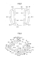
- FIG. 3 is a perspective view from a reverse side of the mounting member
- FIG. 4 is a bottom view of the mounting member
- FIG. 5 is a right side view of the mounting member illustrated in FIG. 4 ;
- FIG. 6 illustrates an example of an interlocking structure
- FIG. 7 is a partial enlarged view of FIG. 6 ;
- FIG. 8 is a cross-sectional view of FIG. 6 ;
- FIG. 9 is another cross-sectional view of FIG. 6 ;
- FIG. 10 is an upper-side perspective view of a fastening member.
- FIG. 1 illustrates an airbag device 1 according to an embodiment of the present invention.
- the airbag device 1 includes an airbag 100 , a cover part 20 , a mounting member 30 , and a fastening member (the fastening member is described below with reference to another drawing).
- the airbag 100 is configured to be inflated by a gas supplied from an inflator (not shown) arranged in the airbag device 1 and is deployed with respect to an occupant by cleaving the cover part 20 .
- the cover part 20 is fixed to a support member (not shown) arranged in the airbag device 1 and is configured to cover the airbag 100 that is folded and accommodated therein.
- the cover part 20 may be made of a resin material such as a thermoplastic elastomer.
- the mounting member 30 is a member that is mounted to an obverse side 21 of the cover part 20 and is visible by the occupant.
- Specific examples of the mounting member 30 include a decorative member such as an emblem of an automobile company. Note that the shape, size, and design of the mounting member 30 are by no way limited to the example illustrated in the drawings.
- a mounting part 40 to which the mounting member 30 is mounted is formed at a central portion of the obverse side 21 of the cover part 20 .
- FIG. 2 is an enlarged view of the mounting part 40 to which the mounting member 30 is mounted.
- the mounting part 40 of the cover part 20 includes rectangular-shaped mounting holes 42 - 1 to 42 - 4 into which U-shaped engaging parts 32 - 1 to 32 - 4 arranged at the mounting member 30 (described below) are inserted.
- the mounting holes 42 - 1 to 42 - 4 are arranged to penetrate through the cover part 20 from its obverse side to its reverse side.
- circular and rectangular mounting holes 44 - 1 to 44 - 8 that penetrate through the cover part 20 from its obverse side to its reverse side surround the mounting holes 42 - 1 to 42 - 4 .
- FIG. 3 is a perspective view of the mounting member 30 from the reverse side.
- FIG. 4 is a bottom view of the mounting member 30 as viewed from the reverse side.
- FIG. 5 is a right side view of the mounting member 30 illustrated in FIG. 4 .
- the mounting member 30 may be made of a metal material such as a hairline-processed aluminum alloy, a resin material such as ABS resin (Acrylonitrile Butadiene Styrene Copolymer), or some other type of material.
- a metal material such as a hairline-processed aluminum alloy
- a resin material such as ABS resin (Acrylonitrile Butadiene Styrene Copolymer), or some other type of material.
- the four U-shaped engaging parts 32 - 1 to 32 - 4 protrude from the reverse side of a base 30 a of the mounting member 30 .
- Positioning bosses 34 - 1 and 34 - 2 and hook parts 36 - 1 to 36 - 6 that engage the cover part 20 are arranged around the reverse side peripheral portion of the base 30 a (not shown in FIG. 5 ).
- the mounting member 30 may be positioned with respect to the mounting part 40 of the cover part 20 .
- the reverse side of the mounting member 30 may be held in close contact with the mounting part 40 .
- the U-shaped engaging parts 32 - 1 to 32 - 4 are arranged into gate shapes that protrude from the reverse side of the mounting member 30 .
- Fastening holes 32 - 1 a to 32 - 4 a to which a fastening member is inserted are formed between the U-shaped engaging parts 32 - 1 to 32 - 4 and the reverse side of the mounting member 30 .
- the U-shaped engaging parts 32 - 1 to 32 - 4 when viewed from the reverse side of the mounting member 30 , are arranged to extend diagonally at a predetermined angle ⁇ with respect to a center line O extending in the longitudinal direction of the mounting member 30 .
- the U-shaped engaging parts 32 - 1 and 32 - 2 are symmetrically arranged on the reverse side of the mounting member 30 with respect to the center line O
- the U-shaped engaging parts 32 - 3 and 32 - 4 are symmetrically arranged on the reverse side of the mounting member 30 with respect to the center line O.
- the four hook parts 36 - 3 to 36 - 6 are arranged to protrude from the reverse side of four corner parts 31 a to 31 d of the mounting member 30 that has a rectangular shape. Note that although the contours of the illustrated corner parts 31 a to 31 d are rounded, the corner parts may also be angular.
- the hook parts 36 - 3 to 36 - 4 are preferably arranged to be symmetrically arranged with respect to the center line O such that the left and right locking strengths may be equal. Note that the same applies to the hook parts 36 - 5 and 36 - 6 .
- the hook parts 36 - 3 and 36 - 6 when viewed from the reverse side of the mounting member 30 , are respectively arranged at the corner parts 31 a and 31 d that are located on one side of the center line O passing through the center of the mounting member 30 .
- the corner parts 31 a and 31 b are arranged opposite the center line O with respect to the extending direction of the U-shaped engaging parts 32 - 1 and 32 - 3 .
- the hook parts 36 - 4 and 36 - 5 when viewed from the reverse side of the mounting member 30 , are respectively arranged at the corner parts 31 b and 31 c that are located on the other side of the center line O passing through the center of the mounting member 30 .
- the corner parts 31 b and 31 c are arranged opposite the center line O with respect to the extending direction of the U-shaped engaging parts 32 - 2 and 32 - 4 .
- openings 35 a and 35 b may be formed in the mounting member 30 as illustrated in the drawings.
- the hook parts 36 - 3 to 36 - 6 arranged at the corner parts 31 a - 31 d may be located at narrow parts 37 a and 37 b between the contour 33 of the mounting member 30 and the openings 35 a and 35 b formed along the contour 33 , for example.
- the openings 35 a and 35 b are holes formed in the mounting member 30 for design and/or cost reasons, for example, and may be through holes penetrating through the obverse and reverse sides of the mounting member 30 or recesses that do not penetrate through the mounting member 30 .
- the openings 35 a and 35 b when viewed from the reverse side of the mounting member 30 , may be formed on the base 30 a at the outer sides of the U-shaped engaging portions 32 - 1 to 32 - 4 .
- the opening 35 a extends from the corner part 31 a to the corner part 31 d that are located on one side of the center line O; and the opening 35 b extends from the corner part 31 b to the corner part 31 c that are located on the other side of the center line O.
- the narrow part 37 a when viewed from the reverse side of the mounting member 30 , is a side peripheral portion between the contour 33 on one side of the center line O passing through the center of the mounting member 30 and the opening 35 a extending along the contour 33 on this side.
- the narrow part 37 b when viewed from the reverse side of the mounting member 30 , is a side peripheral portion between the contour 33 on the other side of the center line O passing through the center of the mounting member 30 and the opening 35 b extending along the contour 33 on this other side.
- the hook part 36 - 3 corresponding to one of the four hook parts includes a column part 36 a protruding from the reverse side of the corner part 31 a and a tip part 36 b bending at the top of the column part 36 a .
- the tip part 36 b of the hook part 36 - 3 when viewed facing the reverse side or the obverse side of the mounting member 30 , are bent outward with respect to the mounting member 30 . That is, the tip part 36 b is bent toward the contour 33 of the corner part 31 a with respect to the position of the corner part 31 a of the hook part 36 - 3 . Note that the same applies to the configurations of the hook parts 36 - 4 , 36 - 5 , and 36 - 6 .
- the tip parts 36 b of the hook parts 36 - 3 to 36 - 6 are claw-like parts that are bent in one way in an outward direction with respect to the contour 33 of the mounting member 30 parallel to a direction perpendicular to the center line O (insertion direction of fastening members as described below).
- the tip parts 36 b of the hook parts 36 - 3 to 36 - 6 may be claw-like parts that are bent in one way in an outward direction with respect to the contour 33 of the mounting member 30 parallel to the center line O.
- tip parts 36 b of the hook parts 36 - 3 to 36 - 6 may be claw-like parts bent in one way in an outward direction with respect to the contour 33 of the mounting member 30 parallel to a direction extending diagonally with respect to the center line O and the direction perpendicular to the center line O.
- the tip parts 36 b when viewed from the obverse side or the reverse side of the mounting member 30 , may protrude outward beyond the contour 33 of the corner parts 31 a to 31 d.
- FIG. 6 illustrates a fastening structure 11 as an embodiment of an interlocking structure according to the present invention.
- FIG. 7 is a partially enlarged view of the fastening structure 11 .
- FIGS. 8 and 9 are cross-sectional views of parts of the fastening structure 11 .
- the fastening structure 11 includes the cover part 20 , the U-shaped engaging parts 32 - 1 to 32 - 4 of the mounting member 30 that protrude from the reverse side 22 of the cover part 20 , and a fastening member 50 that fastens the U-shaped engaging parts 32 - 1 to 32 - 4 of the mounting member 30 to the reverse side 22 of the cover part 20 .
- a fastening member 50 that fastens the U-shaped engaging parts 32 - 1 to 32 - 4 of the mounting member 30 to the reverse side 22 of the cover part 20 .
- an exemplary case of mounting an emblem of an automobile company as the mounting member 30 to the obverse side of the cover part 20 is illustrated.
- the present invention may equally be applied to cases where a member other than an emblem is mounted to the cover part.
- the so-called bolt structure is used in which first and second fastening parts 60 and 70 of the fastening member 50 are inserted through the fastening holes 32 - 1 a to 32 - 4 a of the U-shaped engaging parts 32 - 1 to 32 - 4 so that the U-shaped engaging parts 32 - 1 to 32 - 4 are fastened to the reverse side 22 of the cover part 20 .
- FIG. 10 is an upper side perspective view of the fastening member 50 .
- the fastening member 50 may be formed by molding a thermoplastic resin, for example. As illustrated in FIG. 10 , for example, the fastening member 50 includes the first and second fastening parts 60 and 70 that extend parallel to the X direction (Xa or Xb direction), a connecting part 80 that interconnects base end portions 64 and 74 of the first and second fastening parts 60 and 70 , and detachment preventing parts 90 for preventing the first and second fastening parts 60 and 70 from coming off the U-shaped engaging parts 32 - 1 to 32 - 4 .
- the fastening member 50 is arranged into a C-shape (U-shape) by interposing the connecting part 80 between the base end portions 64 and 74 of the two fastening parts 60 and 70 that extend linearly in the X direction.
- the fastening member 50 may be arranged into a shape other than a U-shape.
- tip portions 62 and 72 of the first and second fastening parts 60 and 70 are tapered so that the first and second fastening parts 60 and 70 may be easily inserted into the fastening holes 32 - 1 a to 32 - 4 a of the U-shaped engaging parts 32 - 1 to 32 - 4 .
- the detachment preventing parts 90 include first contact parts 91 and 93 arranged near the tip portions 62 and 72 of the first and second fastening parts 60 and 70 and second contact parts 92 and 94 arranged near the base end portions 64 and 74 of the first and second fastening parts 60 and 70 .
- the first contact parts 91 and 93 come into contact with side face portions 32 - 2 b and 32 - 4 b of the U-shaped engaging parts 32 - 2 and 32 - 4 (left side of FIG. 6 ), and the second contact parts 92 and 94 come into contact with side face portions 32 - 1 b and 32 - 3 b of the U-shaped engaging parts 32 - 1 and 32 - 3 (right side of FIG. 6 ).
- Step 1 As shown in FIGS. 1-5 , first, the mounting member 30 is mounted to the mounting part 40 formed on the obverse side of the cover part 20 . At this time, the U-shaped engaging parts 32 - 1 to 32 - 4 of the mounting member 30 are inserted through the mounting holes 42 - 1 to 42 - 4 from the obverse side of the mounting part 40 to protrude from the reverse side of the mounting part 40 . Also, the positioning bosses 34 - 1 and 34 - 2 and the hook parts 36 - 1 to 36 - 6 of the mounting member 30 are inserted into the mounting holes 44 - 1 to 44 - 8 of the mounting part 40 to be interlocked with the cover part 20 (first fastening operation).
- the mounting member 30 may be fixed into position with respect to longitudinal and lateral in-plane directions within a plane perpendicular to the mounting direction for mounting the mounting member 30 to the obverse side of the cover part 20 (plane parallel to the mounting surface of the mounting part 40 ).
- the mounting member 30 may be fixed in position with respect to the cover part 20 in the mounting direction for mounting the mounting member 30 to the obverse side of the cover part 20 (normal direction to the mounting surface of the mounting part 40 ).
- the column parts 36 a of the hook parts 36 - 3 to 36 - 6 penetrate through the mounting holes 44 - 5 to 44 - 8 from the obverse side 21 to the reverse side 22 of the cover part 20 , and the tip parts 36 b are hooked and fixed to the reverse side 22 of the cover part 20 .
- Step 2 Viewing the cover part 20 from its reverse side as illustrated in FIG. 6 , the fastening member 50 has the first contact parts 91 and 93 oriented upward and the connecting part 80 positioned at the right side.
- the tip portions 62 and 72 of the first and second fastening parts 60 and 70 are inserted from the right side into the fastening holes 32 - 1 a and 32 - 3 a of the U-shaped engaging parts 32 - 1 and 32 - 3 that protrude from the reverse side of the cover part 20 .
- Step 3 The fastening member 50 is slid further in the Xa direction so that the tip portions 62 and 72 of the first and second fastening parts 60 and 70 are inserted from the right side into the fastening holes 32 - 2 a and 32 - 4 a of the U-shaped engaging parts 32 - 2 and 32 - 4 located at the left side of the cover part 20 .
- the first contact parts 91 and 93 of the fastening member 50 slide against the inner peripheral faces of the fastening holes 32 - 2 a and 32 - 4 a of the U-shaped engaging parts 32 - 2 and 32 - 4 and bend in a direction close to the horizontal direction.
- the fastening member 50 can firmly fasten the U-shaped engaging parts 32 - 1 to 32 - 4 of the mounting member 30 to the cover part 20 by the four bolt structures and prevent the mounting member 30 from coming off the cover part 20 , and at the same time, the reverse side of the mounting member 30 may be stably held in close contact with the mounting part 40 of the cover part 20 .
- the fastening member 50 is configured to restrict movement of the first contact parts 91 and 93 in the Xb direction with respect to the U-shaped engaging parts 32 - 2 and 32 - 4 and movement of the second contact parts 92 and 94 in the Xa direction with respect to the U-shaped engaging parts 32 - 1 and 32 - 3 .
- the fastening member 50 can firmly fasten the U-shaped engaging parts 32 - 1 to 32 - 4 of the mounting member 30 to the cover part 20 , and at the same time, the fastening member 50 may be prevented from coming off the U-shaped engaging parts 32 - 1 to 32 - 4 even when vibrations or a shock is applied, for example.
- the fastening operation of the fastening member 50 merely involves sliding the fastening member 50 in the Xa direction, workability during assembly may be improved and productivity may be increased, for example.
- the first contact parts 91 and 93 may be pushed downward and pulled in the Xb direction at the same time so that the first contact parts 91 and 93 may pass through the U-shaped engaging parts 32 - 1 to 32 - 4 in the Xb direction.
- the fastening member 50 may be removed without the use of special equipment and the mounting member 30 may be unfastened from the cover part 20 with relative ease.
- the hook parts 36 - 3 to 36 - 6 are respectively inserted into and interlocked with the corresponding mounting holes 44 - 5 to 44 - 8 .
- gaps formed between the obverse side 21 of the cover part 20 and the corner parts 31 a to 31 d of the mounting member 30 may be prevented from being enlarged.
- the four corners of the mounting member 30 may be prevented from flapping up from the obverse side 21 of the cover part 20 (toward the occupant side) (see FIG. 1 and FIGS. 6-9 ).
- the narrow parts 37 a and 37 ba that occur as a result of forming the openings 35 a and 35 b along the contour 33 of the mounting member 30 are easily deformed due to their reduced thickness. As such, gaps formed between the obverse side 21 of the cover part 20 and the narrow parts 37 a and 37 b are prone to increase in size.
- the hook part 36 - 1 is provided at a portion of the narrow part 37 a between the corner parts 31 a and 31 d , and in this way, the gap at this portion may be prevented from increasing in size. The same effect may be obtained by the hook part 36 - 2 .
- the hook part 36 - 3 is provided at the corner part 31 a of the narrow part 37 a , and in this way, the gap at the corner part 31 a may be prevented from increasing in size. The same effect may be obtained by the hook parts 36 - 4 to 36 - 6 as well.
- the tip parts 36 b of the hook parts 36 - 3 to 36 - 6 are arranged to bend outward with respect to the mounting member 30 , and in this way, the orientations of the tip parts 36 b may substantially coincide with the curving direction of the mounting member 30 that has a curved shape with its central portion protruding from its outer peripheral portion as illustrated in FIGS. 8 and 9 . Such an arrangement may further prevent the gaps between the obverse side 21 of the cover part 20 and the corner parts 31 a to 31 d from being enlarged.
- the airbag device 1 and the cover part 20 are arranged at a central portion of a steering wheel 200 (see FIG. 1 ) in the above-described embodiment, the arrangement of the airbag device and the cover part of the present invention is not limited to the above.
- the present invention may also be applied to cases of mounting a mounting member to a cover part of an airbag device for a passenger seat that is installed in an instrument panel, an airbag device for a rear seat that is installed in a front seat, or an airbag device for protection against side collision that is installed in a side part of a vehicle body.
- the cover part 20 described above is configured to cover the airbag 100
- the cover part of the present invention is not limited to covering an airbag. That is, the cover part of the present invention may also be configured to cover other members such as a horn switch or a steering shaft.
- the cover part 20 illustrated in FIG. 1 may be arranged at an inner central portion located radially within an annular rim part 201 of the steering wheel 200 and may be configured to cover a member such as a horn switch.
- the rim part 201 is a part that is gripped by the driver, and in FIG. 1 , only a lower portion of the annular rim part 201 is illustrated while other portions are omitted.
- the cover part 20 may be mounted to a spoke portion extending radially inward from the rim part 201 toward the inner central portion of the rim portion 201 , or the cover part 20 may be mounted to a hub portion of the steering wheel 200 (connecting portion between the steering wheel 200 and the steering shaft), for example.
- fastening member 50 described above is configured to be inserted horizontally with respect to the vehicle body
- the fastening member of the present invention may be inserted in any direction including a vertical direction and an oblique direction with respect to the vehicle body.
- the shape of the mounting member 30 does not necessarily have to be rectangular but may be some other polygonal shape having corners, for example.
Abstract
Description
- Patent Document 1: Japanese Laid-Open Patent Publication No. H09-11833
- 1 airbag device
- 11 fastening structure
- 20 cover part
- 21 obverse side
- 22 reverse side
- 30 mounting member
- 30 a base
- 31 a, 31 b, 31 c, 31 d corner part
- 32-1 to 32-4 U-shaped engaging part
- 32-1 a to 32-4 a fastening hole
- 32-1 b to 32-4 b side face portion
- 33 contour
- 34-1, 34-2 positioning boss
- 35 a, 35 b opening
- 36-1 to 36-6 hook part
- 36 a column part
- 36 b tip part
- 37 a, 37 b narrow part
- 40 mounting part
- 42-1 to 42-4 mounting hole
- 44-1 to 44-8 mounting hole
- 50 fastening member
- 60 first fastening part
- 62, 72 tip portion
- 64, 74 base end portion
- 70 second fastening part
- 80 connecting part
- 90 detachment preventing part
- 91, 93 first contact part
- 92, 94 second contact part
- 100 airbag
- 200 steering wheel
- 201 rim part
Claims (14)
Applications Claiming Priority (3)
| Application Number | Priority Date | Filing Date | Title |
|---|---|---|---|
| JP2012-218159 | 2012-09-28 | ||
| JP2012218159A JP5705809B2 (en) | 2012-09-28 | 2012-09-28 | Locking structure, mounting member, and airbag device |
| PCT/JP2013/074237 WO2014050523A1 (en) | 2012-09-28 | 2013-09-09 | Interlocking structure, mounting member, and airbag device |
Publications (2)
| Publication Number | Publication Date |
|---|---|
| US20150239417A1 US20150239417A1 (en) | 2015-08-27 |
| US9457757B2 true US9457757B2 (en) | 2016-10-04 |
Family
ID=50387931
Family Applications (1)
| Application Number | Title | Priority Date | Filing Date |
|---|---|---|---|
| US14/427,057 Active US9457757B2 (en) | 2012-09-28 | 2013-09-09 | Interlocking structure, mounting member, and airbag device |
Country Status (3)
| Country | Link |
|---|---|
| US (1) | US9457757B2 (en) |
| JP (1) | JP5705809B2 (en) |
| WO (1) | WO2014050523A1 (en) |
Cited By (1)
| Publication number | Priority date | Publication date | Assignee | Title |
|---|---|---|---|---|
| US11691589B2 (en) * | 2019-06-26 | 2023-07-04 | Hyundai Mobis Co., Ltd. | Driver-side airbag device |
Families Citing this family (6)
| Publication number | Priority date | Publication date | Assignee | Title |
|---|---|---|---|---|
| JP6026249B2 (en) * | 2012-11-29 | 2016-11-16 | 日本プラスト株式会社 | Cover body of airbag device |
| WO2014120743A1 (en) * | 2013-01-29 | 2014-08-07 | Tk Holdings Inc. | Illuminated emblem assembly for connection to an airbag cover |
| US10000175B2 (en) * | 2014-06-05 | 2018-06-19 | Key Safety Systems, Inc. | Driver airbag cover with emblem |
| JP6277910B2 (en) * | 2014-08-22 | 2018-02-14 | トヨタ自動車株式会社 | Vehicle assembly structure and vehicle assembly part manufacturing method |
| JP1530584S (en) * | 2014-09-24 | 2018-07-30 | ||
| JP1530315S (en) * | 2015-01-06 | 2015-08-03 |
Citations (19)
| Publication number | Priority date | Publication date | Assignee | Title |
|---|---|---|---|---|
| JPH08301044A (en) | 1995-05-11 | 1996-11-19 | Nippon Plast Co Ltd | Cover body of air bag device |
| JPH0911838A (en) | 1995-04-28 | 1997-01-14 | Nippon Seiko Kk | Cover body of air bag device |
| JPH0911833A (en) | 1995-06-28 | 1997-01-14 | Nippon Plast Co Ltd | Cover body of air bag device |
| JPH0948315A (en) | 1995-08-09 | 1997-02-18 | Nippon Name Plate Kogyo Kk | Emblem for air bag handle |
| US5678851A (en) | 1995-04-28 | 1997-10-21 | Nihon Plast Co., Ltd. | Airbag module cover |
| JPH1035389A (en) | 1996-07-29 | 1998-02-10 | Nippon Plast Co Ltd | Covering member of air bag device |
| US6105999A (en) * | 1997-10-06 | 2000-08-22 | Serigraph, Inc. | Airbag cover assembly |
| US20010002965A1 (en) | 1999-12-07 | 2001-06-07 | Shoichi Ibe | Structure for mounting to steering wheel |
| US20010054810A1 (en) * | 2000-06-27 | 2001-12-27 | Toyoda Gosei Co., Ltd. | Air bag module mounting structure |
| JP2003011764A (en) | 2001-07-05 | 2003-01-15 | Ashimori Ind Co Ltd | Air bag cover |
| US6568704B2 (en) * | 2000-06-12 | 2003-05-27 | Toyoda Gosei Co., Ltd. | Air bag cover with ornament |
| US20030214120A1 (en) * | 2002-05-14 | 2003-11-20 | Hitoshi Iida | Airbag cover having ornament |
| US6692016B2 (en) * | 2000-02-29 | 2004-02-17 | Takata Corporation | Cover for air bag device |
| US7004497B2 (en) * | 2003-01-07 | 2006-02-28 | General Motors Corporation | Styling flexible driver air bag module and method of making same |
| JP2009280059A (en) | 2008-05-21 | 2009-12-03 | Ashimori Ind Co Ltd | Airbag cover and airbag device |
| US8196953B2 (en) * | 2007-03-05 | 2012-06-12 | Takata-Petri Ag | Film plate for an airbag cover |
| US20140145419A1 (en) * | 2012-11-29 | 2014-05-29 | Nihon Plast Co., Ltd. | Cover body for airbag device |
| US20140210191A1 (en) * | 2013-01-29 | 2014-07-31 | Tasus Canada Corporation | Illuminated emblem assembly for connection to an airbag cover |
| US20150108742A1 (en) * | 2013-01-29 | 2015-04-23 | Tk Holdings Inc. | Illuminated emblem assembly for connection to an airbag cover |
-
2012
- 2012-09-28 JP JP2012218159A patent/JP5705809B2/en active Active
-
2013
- 2013-09-09 US US14/427,057 patent/US9457757B2/en active Active
- 2013-09-09 WO PCT/JP2013/074237 patent/WO2014050523A1/en active Application Filing
Patent Citations (23)
| Publication number | Priority date | Publication date | Assignee | Title |
|---|---|---|---|---|
| JPH0911838A (en) | 1995-04-28 | 1997-01-14 | Nippon Seiko Kk | Cover body of air bag device |
| US5678851A (en) | 1995-04-28 | 1997-10-21 | Nihon Plast Co., Ltd. | Airbag module cover |
| JPH08301044A (en) | 1995-05-11 | 1996-11-19 | Nippon Plast Co Ltd | Cover body of air bag device |
| JPH0911833A (en) | 1995-06-28 | 1997-01-14 | Nippon Plast Co Ltd | Cover body of air bag device |
| JPH0948315A (en) | 1995-08-09 | 1997-02-18 | Nippon Name Plate Kogyo Kk | Emblem for air bag handle |
| JPH1035389A (en) | 1996-07-29 | 1998-02-10 | Nippon Plast Co Ltd | Covering member of air bag device |
| US6105999A (en) * | 1997-10-06 | 2000-08-22 | Serigraph, Inc. | Airbag cover assembly |
| US20010002965A1 (en) | 1999-12-07 | 2001-06-07 | Shoichi Ibe | Structure for mounting to steering wheel |
| JP2001225703A (en) | 1999-12-07 | 2001-08-21 | Tokai Rika Co Ltd | Mounting structure of plate body on pad cover |
| US6692016B2 (en) * | 2000-02-29 | 2004-02-17 | Takata Corporation | Cover for air bag device |
| US7000941B2 (en) * | 2000-02-29 | 2006-02-21 | Takata Corporation | Cover for air bag device |
| US6568704B2 (en) * | 2000-06-12 | 2003-05-27 | Toyoda Gosei Co., Ltd. | Air bag cover with ornament |
| US20010054810A1 (en) * | 2000-06-27 | 2001-12-27 | Toyoda Gosei Co., Ltd. | Air bag module mounting structure |
| JP2003011764A (en) | 2001-07-05 | 2003-01-15 | Ashimori Ind Co Ltd | Air bag cover |
| US20030214120A1 (en) * | 2002-05-14 | 2003-11-20 | Hitoshi Iida | Airbag cover having ornament |
| US7004497B2 (en) * | 2003-01-07 | 2006-02-28 | General Motors Corporation | Styling flexible driver air bag module and method of making same |
| US8196953B2 (en) * | 2007-03-05 | 2012-06-12 | Takata-Petri Ag | Film plate for an airbag cover |
| JP2009280059A (en) | 2008-05-21 | 2009-12-03 | Ashimori Ind Co Ltd | Airbag cover and airbag device |
| US20110062688A1 (en) * | 2008-05-21 | 2011-03-17 | Ashimori Industry Co., Ltd. | Airbag cover and airbag device |
| US8210565B2 (en) * | 2008-05-21 | 2012-07-03 | Ashimori Industry Co., Ltd. | Airbag cover and airbag device |
| US20140145419A1 (en) * | 2012-11-29 | 2014-05-29 | Nihon Plast Co., Ltd. | Cover body for airbag device |
| US20140210191A1 (en) * | 2013-01-29 | 2014-07-31 | Tasus Canada Corporation | Illuminated emblem assembly for connection to an airbag cover |
| US20150108742A1 (en) * | 2013-01-29 | 2015-04-23 | Tk Holdings Inc. | Illuminated emblem assembly for connection to an airbag cover |
Non-Patent Citations (1)
| Title |
|---|
| International Search Report mailed on Dec. 17, 2013. |
Cited By (1)
| Publication number | Priority date | Publication date | Assignee | Title |
|---|---|---|---|---|
| US11691589B2 (en) * | 2019-06-26 | 2023-07-04 | Hyundai Mobis Co., Ltd. | Driver-side airbag device |
Also Published As
| Publication number | Publication date |
|---|---|
| WO2014050523A1 (en) | 2014-04-03 |
| US20150239417A1 (en) | 2015-08-27 |
| JP5705809B2 (en) | 2015-04-22 |
| JP2014069731A (en) | 2014-04-21 |
Similar Documents
| Publication | Publication Date | Title |
|---|---|---|
| US9457757B2 (en) | Interlocking structure, mounting member, and airbag device | |
| US6672027B2 (en) | Pillar trim mounting structure | |
| US9168877B2 (en) | Airbag unit, fastening structure, and fastening member | |
| US8297676B2 (en) | Vehicle interior trim panel | |
| US8646827B2 (en) | Vehicle interior assembly | |
| US8303010B2 (en) | Vehicle interior trim panel | |
| US7213833B2 (en) | Emblem, module cover and airbag apparatus | |
| US8104813B2 (en) | Vehicle interior trim panel | |
| EP2740633B1 (en) | Door trim | |
| US20110221172A1 (en) | Vehicle interior trim panel | |
| US20180126940A1 (en) | Glove box rail with integrated airbag support | |
| US20050067815A1 (en) | Airbag cover emblem attachment apparatus and method | |
| US9868334B2 (en) | Installation structure for vehicle-mounted device | |
| WO2014042008A1 (en) | Mounting structure for airbag module | |
| EP2468580B1 (en) | Interior material mounting structure | |
| JP5987652B2 (en) | Assembly structure of assist grip | |
| CN108495759B (en) | Interior decoration fitting for vehicle | |
| KR101560542B1 (en) | Apparatus for coupling passenger airbag module | |
| CN205524480U (en) | Car stand backplate and car | |
| JP6256759B2 (en) | Meter cluster mounting structure | |
| US9221416B2 (en) | Trim assembly for covering airbag | |
| JP2010095225A (en) | Incorrect attachment prevention structure for front pillar trim | |
| KR100624015B1 (en) | Structure for fixing retainer for passenger air bag | |
| KR20090028099A (en) | Air bag module of vehicles | |
| KR101920301B1 (en) | A driver airbag apparatus |
Legal Events
| Date | Code | Title | Description |
|---|---|---|---|
| AS | Assignment |
Owner name: TAKATA CORPORATION, JAPAN Free format text: ASSIGNMENT OF ASSIGNORS INTEREST;ASSIGNORS:KAWABE, TAKUMI;FUJIWARA, SHUHEI;ONOHARA, KEISUKE;AND OTHERS;REEL/FRAME:035125/0813 Effective date: 20150305 |
|
| STCF | Information on status: patent grant |
Free format text: PATENTED CASE |
|
| FEPP | Fee payment procedure |
Free format text: PAYOR NUMBER ASSIGNED (ORIGINAL EVENT CODE: ASPN); ENTITY STATUS OF PATENT OWNER: LARGE ENTITY |
|
| AS | Assignment |
Owner name: JOYSON SAFETY SYSTEMS JAPAN K.K., JAPAN Free format text: ASSIGNMENT OF ASSIGNORS INTEREST;ASSIGNOR:TAKATA CORPORATION;REEL/FRAME:045938/0931 Effective date: 20180410 |
|
| AS | Assignment |
Owner name: DEUTSCHE BANK TRUST COMPANY AMERICAS, NEW YORK Free format text: SECURITY INTEREST;ASSIGNOR:JOYSON SAFETY SYSTEMS JAPAN K. K.;REEL/FRAME:046286/0789 Effective date: 20180525 |
|
| MAFP | Maintenance fee payment |
Free format text: PAYMENT OF MAINTENANCE FEE, 4TH YEAR, LARGE ENTITY (ORIGINAL EVENT CODE: M1551); ENTITY STATUS OF PATENT OWNER: LARGE ENTITY Year of fee payment: 4 |
|
| AS | Assignment |
Owner name: DEUTSCHE BANK TRUST COMPANY AMERICAS, AS SECURITY AGENT FOR THE SECURED PARTIES, NEW YORK Free format text: SECURITY INTEREST;ASSIGNOR:JOYSON SAFETY SYSTEMS JAPAN K.K.;REEL/FRAME:057828/0338 Effective date: 20211004 Owner name: JOYSON SAFETY SYSTEMS JAPAN K.K., JAPAN Free format text: RELEASE BY SECURED PARTY;ASSIGNOR:DEUTSCHE BANK TRUST COMPANY AMERICAS, AS SECURITY AGENT FOR THE SECURED PARTIES;REEL/FRAME:057775/0655 Effective date: 20211004 |
|
| AS | Assignment |
Owner name: JOYSON SAFETY SYSTEMS JAPAN G.K., JAPAN Free format text: CHANGE OF NAME;ASSIGNOR:JOYSON SAFETY SYSTEMS JAPAN K.K.;REEL/FRAME:062218/0618 Effective date: 20221101 |
|
| AS | Assignment |
Owner name: JOYSON SAFETY SYSTEMS JAPAN G.K., JAPAN Free format text: ASSIGNEE CHANGE OF ADDRESS;ASSIGNOR:JOYSON SAFETY SYSTEMS JAPAN G.K.;REEL/FRAME:062299/0879 Effective date: 20230105 |