US9464465B2 - Handle assembly - Google Patents
Handle assembly Download PDFInfo
- Publication number
- US9464465B2 US9464465B2 US13/831,221 US201313831221A US9464465B2 US 9464465 B2 US9464465 B2 US 9464465B2 US 201313831221 A US201313831221 A US 201313831221A US 9464465 B2 US9464465 B2 US 9464465B2
- Authority
- US
- United States
- Prior art keywords
- operative
- lock slide
- lock
- pivot
- housing
- Prior art date
- Legal status (The legal status is an assumption and is not a legal conclusion. Google has not performed a legal analysis and makes no representation as to the accuracy of the status listed.)
- Active, expires
Links
- 230000007246 mechanism Effects 0.000 claims abstract description 50
- 230000000712 assembly Effects 0.000 description 8
- 238000000429 assembly Methods 0.000 description 8
- 230000008901 benefit Effects 0.000 description 1
- 230000008859 change Effects 0.000 description 1
- 238000005516 engineering process Methods 0.000 description 1
- 230000037431 insertion Effects 0.000 description 1
- 238000003780 insertion Methods 0.000 description 1
- 230000004044 response Effects 0.000 description 1
Images


Classifications
-
- E—FIXED CONSTRUCTIONS
- E05—LOCKS; KEYS; WINDOW OR DOOR FITTINGS; SAFES
- E05B—LOCKS; ACCESSORIES THEREFOR; HANDCUFFS
- E05B85/00—Details of vehicle locks not provided for in groups E05B77/00 - E05B83/00
- E05B85/10—Handles
- E05B85/14—Handles pivoted about an axis parallel to the wing
- E05B85/16—Handles pivoted about an axis parallel to the wing a longitudinal grip part being pivoted at one end about an axis perpendicular to the longitudinal axis of the grip part
-
- Y—GENERAL TAGGING OF NEW TECHNOLOGICAL DEVELOPMENTS; GENERAL TAGGING OF CROSS-SECTIONAL TECHNOLOGIES SPANNING OVER SEVERAL SECTIONS OF THE IPC; TECHNICAL SUBJECTS COVERED BY FORMER USPC CROSS-REFERENCE ART COLLECTIONS [XRACs] AND DIGESTS
- Y10—TECHNICAL SUBJECTS COVERED BY FORMER USPC
- Y10T—TECHNICAL SUBJECTS COVERED BY FORMER US CLASSIFICATION
- Y10T292/00—Closure fasteners
- Y10T292/57—Operators with knobs or handles
Definitions
- Handle assemblies are mechanical apparatuses that are typically used to operate latches that releasably hold two elements in closed relation. Such elements for example may include a closure member and a body member.
- latch assemblies may be used to releasably hold a closure member such as a door or hatch in a closed position relative to a body member such as a door frame or hatch frame.
- Handle and latch assemblies may benefit from improvements.
- a handle assembly may include an improved inside release mechanism.
- the handle assembly may include a housing, including a first/front side and a second/rear side.
- a handle assembly is typically installed through an opening in a door, hatch, or other closure member such that the front side faces outwardly and the rear side is located inside the door.
- the handle assembly may include a handle that is accessible by a user on the front side of the housing. Such a handle may be pulled by a user to cause the handle assembly to operate a latch mechanism in order to enable opening of a door, hatch or other closure member by the user.
- the handle assembly may include a lock mechanism (e.g., a cylinder lock) that includes a key receiving receptacle on the front side of the housing. Rotating a key in one direction (e.g., clockwise) may lock the lock mechanism, such that the handle assembly is in a locked state that prevents the handle assembly and the inside release mechanism from being able to operate the latch mechanism. Also, rotating the key in an opposite direction (e.g., counter-clockwise) may place the handle assembly in an unlocked state, such that the handle assembly and the inside release are both operative to operate the latch mechanism.
- a lock mechanism e.g., a cylinder lock
- Examples of rotary latches that are operated via handle assemblies are shown in U.S. Pat. No. 4,896,906 issued Jan. 30, 1990, which is hereby incorporated herein by reference in its entirety.
- the handle of the described handle assembly may include a first end that is in pivoting connection with the housing on the front side of the housing.
- the handle may include a second end that includes a shaft.
- Such a shaft may extend inwardly from the second end of the handle through an aperture in the housing and into engagement with portions of the handle assembly on the rear side of the housing.
- Such portions of the housing assembly on the rear side may include a trigger that is in pivoting connection with the housing on the rear side of the housing.
- the rear side of the housing may also include a lock slide that is operative to slide (relative to the housing) longitudinally between a retracted position and an extended position.
- the rear side of the housing may include one or more lever arms in pivoting connection with the housing.
- Such lever arms may include at least one aperture therethrough to which a linkage such as rod may be mounted which connects the at least one lever arm to a release paw of a latch mechanism.
- the shaft of the handle may pull on the trigger and cause the trigger to pivot.
- the trigger may include a projection that is positioned to urge (e.g., push) a first end of the lock slide when the trigger is pivoted via the handle.
- the lock side may slide from the retracted position to the extended position, which movement urges the lever arms to pivot in a direction that moves a linkage and thereby operates the latch mechanism.
- the inside release member may be mounted in sliding connection with the housing, such that the inside release member is operative to slide longitudinally between a retracted position and an extended position.
- the inside release may include an aperture to which a linkage may be connected which places the inside release in operative connection with another pivoting handle mounted to another portion of the closure member (such as an inside portion of a door or hatch).
- the inside release member When the inside release member is slid (via a linkage) from the first position to the second position, the inside release member may be operative to engage a second end of the lock slide and cause the lock side to slide from the retracted position to the extended position (as described above) and urge the at least one lever arm to pivot in a direction that moves a linkage and thereby operates the latch mechanism.
- the inside release is operative to cause the lever arms to pivot without causing the trigger to pivot.
- the lock slide is also operative to pivot with respect to the housing between a first pivot position, and a second pivot position.
- first pivot position the first and second ends of the lock slide are oriented such that both the trigger and the inside release member are operative push the lock slide so that it slides between the retracted and extended positions and cause the lever arms to pivot.
- second pivot position the first and second ends of the lock side are not orientated in a manner that enables the trigger and inside release member to push the lock slide between the retracted and extended positions.
- FIG. 1 is a front isometric view of an example handle assembly showing a handle in a retracted position.
- FIG. 2 is a front isometric view of an example handle assembly showing a handle in an extended position.
- FIG. 3 is a rear isometric view of an example handle assembly when a handle is in a retracted position.
- FIG. 4 is a rear isometric view of an example handle assembly when a handle is in an extended position.
- FIG. 5 is a rear isometric view of an example handle assembly when a handle is in a retracted position.
- FIG. 6 is a rear isometric view of an example handle assembly when a handle is in an extended position.
- FIG. 7 is a cross-sectional view of an example handle assembly when a handle is in a retracted position.
- FIG. 8 is a cross-sectional view of an example handle assembly when a handle is in an extended position.
- FIG. 9 is a rear isometric view of an example handle assembly when an inside release member is in an extended position.
- FIG. 10 is a rear isometric view of an example handle assembly when a lock slide is in a pivot position that places the handle assembly in a locked state.
- FIG. 11 is a rear isometric view of an example handle assembly when a lock slide is in a pivot position that places the handle assembly in a locked state and an inside release member is in an extended position.
- FIG. 12 is a cross-sectional view of an example handle assembly when a lock slide is in a pivot position that places the handle assembly in a locked state.
- the handle assembly 102 includes a housing 104 which serves as a receptacle for a pivotable handle 106 on a first/front facing side 108 of the housing 104 .
- the handle When a user grasps and pulls on the handle, the handle is operative to pivot from the retracted position shown in FIG. 1 , to an extended position shown in the example 200 in FIG. 2 . Pivoting of the handle 106 in this manner is operative to cause components mounted on the rear side of the housing to operate.
- the handle 106 may include a shaft 202 that extends inwardly through an aperture 204 through the housing 104 , which shaft is operative to engage components of the handle assembly on the rear side of the housing assembly.
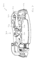
- FIG. 3 illustrates a rear view 300 of the handle assembly showing the second/rear side 302 of the housing while the handle is in the retracted position.
- an end 304 of the shaft 202 is operative to extend to the rear side 302 into engagement with a pivotable member referred to herein as a trigger 306 .
- a trigger 306 may be mounted via a shaft between two parallel brackets 308 , 310 that are connected to and extend outwardly from the rear side 302 of the housing 104 .
- the shaft 202 includes an aperture 313 bounded on one side by a rounded surface 338 .
- the rounded surface includes the cylindrical surface of a roller mounted to the end 304 of the shaft 202 .
- the roller 338 may include portions that extend in holes 340 in opposed sides of the shaft 202 so that the roller is operative to rotate freely with respect the shaft 202 .
- the end 304 of the shaft 202 may include a pin or bolt that extends through a hole in the roller.
- the trigger 306 is positioned to extend through the aperture 314 of the shaft 202 .
- the trigger is operative to pivot between a first pivot position (as shown in FIG. 3 ) and a second pivot position responsive to the end 304 of the shaft 202 moving toward the rear side of the housing when the handle is pulled by a user from the retracted position (shown in FIG. 1 ) to the extended position (shown in FIG. 2 ).
- the roller 338 is operative to roll and travel along a surface 342 of the trigger (a portion of which may include a concave surface).
- the roller and trigger arrangement is operative to reduce wear and friction associated with relative movements between the shaft and the trigger.
- the handle assembly may further include a lock slide 320 in movable connection with the rear side of the housing.
- the lock slide 320 When the lock slide 320 is in an operative position, the trigger is operative to move the lock slide when the trigger pivots to the second pivot position.
- FIG. 4 illustrates a rear view 400 of the handle assembly 102 showing the second/rear side 302 of the housing 104 while the handle is in the extended position and the trigger 306 has pivoted to the second pivot position.
- the handle assembly 102 may also include a spring 402 that is operative to bias the trigger member 306 to pivot from the second pivot position (shown in FIG. 4 ) back to the first pivot position (shown in FIG. 3 ).
- the handle assemble 102 further includes at least one lever arm, which in this example includes two lever arms 312 and 314 .
- Such lever arms are operative to pivot with respect to shafts 316 , 318 connected to the rear side 302 housing 104 responsive to movement of the lock slide 320 .
- Such shafts for example may extend through apertures in the lever arms.
- the shafts correspond to bolts that are in threaded connection with the housing.
- that shafts may be connected via other fastening mechanisms (e.g., via welds).
- This described example of the handle assembly may include an inside release mechanism 322 .
- the operation of either the inside release mechanism 322 and/or pivoting of the handle to the extended position is operative to cause the lock slide 320 to move in a manner which causes the lever arms 312 , 314 to pivot from the first pivot positions (shown in FIG. 3 ) to the second pivot positions (shown in FIG. 4 ).
- lever arms 312 , 314 may include one or more apertures 324 therethrough, which may be used to connect a linkage (e.g., such as a rod).
- a linkage e.g., such as a rod
- a latch mechanism e.g., such as a rotary latch mechanism
- the described handle assembly may be mounted to a door/hatch so as to provide the door with a user operated handle capable of unlatching the door/hatch. Pulling of the handle is operative to cause the lever arms to pivot, which in turn causes the connected linkages to operate a latch mechanism (also mounted to the door/hatch and/or the described handle assembly) to unlatch the door/hatch from a door/hatch frame of a vehicle or other structure.
- a linkage may be mounted to an aperture 324 of one of the lever arms via a rod adapter that is operative to receive a rod or other linkages therein and fasten the rod to the aperture 324 . Examples of linkages and latch mechanisms that may be connected to the described handle assembly are shown in U.S. Pat. No. 4,896,906.
- FIG. 5 illustrates a rear view 500 of the handle assembly 102 without the release mechanism 322 (shown in FIGS. 3 and 4 ) while the handle is in the retracted position and the trigger 306 is in the first pivot position.
- the lock slide 320 may include a shaft 502 positioned between opposed first and second ends 506 , 508 of the lock slide 320 . Such a shaft 502 is orientated to extend away from the rear side 302 of the housing 104 .
- Each of the lever arms 312 , 314 may include respective ends including apertures 504 , through which the shaft 502 of the lock slide 320 extends.
- the lock slide 320 is operative to slide longitudinally from a retracted position to an extended position (i.e., slide back and forth along a line that extends through the first end 506 and the second end 508 ).
- FIG. 5 shows the lock slide 320 in the retracted position.
- FIG. 6 shows an example view 600 in which the lock slide 320 has slid to the extended position.
- the shaft 502 of the lock slide is operative to urge the lever arms 312 , 314 to pivot such that the portions of the lever arms that include the apertures 324 for connecting linkages, move inwardly (i.e., closer to the trigger 306 as shown in FIG. 6 ).
- the handle assembly may include at least one spring 602 that is mounted so as to urge the lever arms 312 , 314 to pivot back to the first pivot positions of the lever arms (shown in FIG. 5 ).
- tension from the spring 602 is operative to cause the lever arms 312 , 314 to pivot to the first pivot positions, which in turn urges the lock slide to slide from the extended position (shown in FIG. 6 ) to the retracted position (shown in FIG. 5 ).
- the lock slide 320 is operative to pivot between a first pivot position and a second pivot position generally with respect to the location of the shaft 502 .
- FIGS. 3-6 all show the lock slide 320 in the first pivot position. In the first pivot position, the lock slide is operative to be urged to slide from the retracted position to the extended position responsive to either the trigger 306 or the inside release mechanism 322 (shown in FIGS. 3 and 4 ).
- FIG. 7 illustrates a cross-sectional view 700 of the handle assembly 102 showing the second/rear side 302 of the housing while the handle 106 is in the retracted position and the lock slide 320 is in the first pivot position.
- the trigger 306 may include a projection 702 that is located adjacent the first end 506 of the lock slide when the lock slide is in the first pivot position.
- the projection is operative to urge the second end 508 of the lock slide so that the lock slide moves from the retracted position shown in FIG. 7 to the extended position.
- FIG. 8 illustrates a cross-sectional view 800 of the handle assembly 102 showing the second/rear side 302 of the housing after the handle 106 has been moved to the extended position.
- the pivoting of the trigger 306 to the second pivot position has caused the projection 702 to move in a longitudinal direction 806 of the lock slide 320 , to cause the lock slide to move longitudinally to the second position (shown in FIG. 8 ).
- the lock slide 320 may include a lower slot 802 in which a projection 804 from the housing may project. Such a projection 804 of the housing may limit longitudinal movement of the lock slide 320 relative to the housing 104 while still permitting the lock slide to pivot around the projection 804 .
- the inside release mechanism may be used instead.
- the inside release mechanism 322 may include an inside release member 326 that is operative to slide longitudinally between a retracted position (shown in FIG. 3 ), and an extended position, generally in the same directions 806 (shown in FIG. 8 ) that the lock slide 320 is operative to longitudinally slide.
- FIG. 9 illustrates a rear view 900 of the handle assembly 102 showing the second/rear side 302 of the housing 104 while the handle is in the retracted position and the trigger 306 remains in the first pivot position.
- the inside release member 326 is shown after having moved longitudinally to the extended position of the inside release member.
- the inside release member 326 includes an engagement portion 902 .
- the second end of the lock slide includes a projection 904 that extends generally outwardly from the rear side of the housing.
- the engagement portion 902 is operative to contact the second end of the lock side via contact with the projection 904 and urge the lock slide to slide from the retracted position (shown in FIG. 3 ) to the extended position of the lock slide (shown in FIG. 9 ).
- this operation of the inside release mechanism 322 is operative to cause the lever arms 312 , 314 to move from the first pivot positions (shown in FIG. 3 ) to the second pivot positions (shown in FIG. 9 ).
- the engagement portion 902 may include a concave face that is operative to engage with the cylindrically shaped side of the projection 904 .
- the engagement portion and the projection may have other shapes and configurations (e.g., such as generally flat surfaces that contact each other).
- the inside release mechanism may include a mount member 906 that is operative to mount the inside release member 326 to the housing 104 .
- a mount member may include a cavity 908 therein, in which an end 912 of the inside release member is operative to slide.
- the mount member is mounted to the housing via the same shafts/bolts 316 , 318 that serve as shafts for the lever arms 312 , 314 .
- the mount member 906 may be mounted via different and/or other types of fasteners to the housing 104 of the handle assembly 102 .
- the inside release member 326 may include an aperture 910 through a projection portion 914 .
- Such an aperture 910 may be used to connect the inside release member 326 (via rods or other linkages) to another handle.
- another handle may be located on an inside face of a door, while the described handle assembly is mounted on the same door but with the handle of the described handle assembly located on an outside face of a door.
- FIG. 9 the lock slide is orientated in the first pivot position.
- the projection 904 of the lock slide is aligned with the engagement portion 902 of the inside release member 326 .
- FIG. 10 illustrates a rear view 1000 of the handle assembly showing the second/rear side 302 of the housing while the handle is in the retracted position and the inside release member 326 is in the retracted position.
- the lock slide 320 is rotated to the second pivot position.
- the projection 904 of the lock slide 320 is no longer aligned with the engagement portion 902 of the inside release member.
- FIG. 10 illustrates a rear view
- the projection portion 914 of the inside release member 326 may extend further outwardly than the engagement portion 902 .
- the projection portion 914 may not be orientated to contact the projection 904 of the lock slide 320 . Rather the projection portion 914 of the inside release member may extend above the projection 904 of the lock slide.
- the projection 904 of the lock slide moves from the first pivot position to the second pivot position of the lock slide, the projection 904 of the lock slide is operative to pass underneath the projection portion 914 of the inside release member.
- FIG. 11 illustrates a rear view 1100 of the handle assembly 102 showing the second/rear side 302 of the housing 104 with the lock slide 320 in the second pivot position, and with the inside release member 326 moved to the extended position. Because the projection 904 of the lock slide is no longer aligned with the engagement portion 902 , movement of the inside release member 326 from the retracted position (shown in FIG. 10 ) to the extended position (shown in FIG. 11 ) does not cause the lock slide 320 to slide from the retracted position of the lock slide (shown in FIG. 10 ) to the extended position of the lock slide (such as shown in FIG. 9 ). Thus in FIG. 11 , the lock slide 320 is still shown in the retracted position, with the engagement portion 902 having traveling beside the projection 904 .
- the lever arms remain in the first pivot positions and did not move to the second pivot positions of the lever arms (such as shown in FIG. 9 ).
- the example handle assembly 102 is in a locked configuration.
- the lock slide is pivoted to the first pivot position (as shown in FIGS. 7-9 )
- the handle assembly 102 is in an unlocked state.
- an example embodiment of the handle assembly may include a lock mechanism.
- FIG. 1 shows an example of a lock mechanism 110 mounted to the housing 104 that is in the form of a cylinder lock.
- the handle 106 includes an aperture 112 through the end of the handle that is in pivoting connection with the housing. Such an aperture may expose an end of the lock cylinder for enabling the insertion of a key 114 .
- FIG. 12 illustrates a cross-sectional view 1200 of the handle assembly 102 , which shows an example configuration of the cylinder lock 110 .
- the cylinder extends from the front side 108 of the housing 104 to the rear side 302 of the housing above a shaft 1202 through the lower portion of handle 106 (at which the handle pivots).
- the handle and lock mechanism may have different configurations.
- the lock mechanism 110 may be position to extend through an opening in the housing that is below, above and/or beside the handle.
- a compatible key when inserted in the cylinder lock, is operative to be rotated by a user to cause a rotational portion of the cylinder lock to rotate that is located on the rear side of the housing.
- a rotational portion of the cylinder lock may correspond to a shaft 328 to which is mounted a lock arm 330 .
- Such a lock arm 330 may be operative to rotate back and forth responsive to a key 114 turning clockwise and counter clockwise in the lock mechanism.
- the lock arm 330 may include first and second projections 332 , 334 . As shown in FIG. 10 , such projections may extent on opposed sides of the projection 904 of the lock slide. Thus clockwise and counter-clockwise rotation of the lock arm (responsive to a key turning in the cylinder lock) is operative to cause the projections 332 , 334 to alternately contact the projection 904 of the lock slide 320 so as to urge the lock slide to move between the second rotational position (shown in FIG. 10 ) and the first rotational position (such as shown in FIG. 3 ). As shown in FIG. 11 , the engagement portion 902 of the inside release member 326 may be located on the inside release member such that it does not interfere with the lock arm. For example, the engagement portion 902 may be configured such that the engagement portion passes over an end of first projection 332 when the inside release member 326 moves to the extended position.
- an example embodiment of the lock arm 330 may include one or more apertures 336 , to which a rod or other linkage may be connected.
- a linkage may connect the lock arm 330 to a manually operated button or other type of actuator that is operative to cause the lock arm to rotate and cause the lock slide to change between the first and second pivot positions of the lock slide.
- a linkage connected to the lock arm 330 may provide a further manner in which to place the handle assembly 102 in locked or unlocked states.
- the lock mechanism 110 may not be mounted to the housing 104 of the handle assembly.
- a lock mechanism may be mounted to a different location on a door/hatch and may be connected to the lock arm 330 via a linkage.
- FIG. 12 also shows a cross-section of the mount member 906 of the inside release mechanism 322 .
- a mount member may include a lower opening or channel 1204 in which a projection 1206 of the inside release member may extend.
- a projection 1206 in the channel 1204 may limit movement of the inside release member 326 between the retracted and extended positions described previously.
- the top of the mount member 906 may include an opening 1208 that allows an upper contour 1210 of the projection member 914 to slope upwardly from positions within the mount member 906 (when in the retracted position) so that the projection member 914 increases in cross-sectional height to accommodate the aperture 910 .
- the lock arm 330 has been shown mounted directly to the rotational portion 328 of the lock mechanism (see FIG. 3 ).
- the lock arm may be mounted in pivoting connection with a portion of the housing, and a linkage connected to the rotational portion of the lock mechanism may be operative to engage the lock arm and cause the lock arm to rotate.
- alternative embodiments may not include an inside release mechanism.
- such an alternative embodiment may have a form similar to that shown in FIGS. 5 and 6 .
- alternative handle assemblies may include a shaft which engages a trigger (such as the shaft 202 shown in FIG. 3 ) which has a roller 338 to enable the trigger 306 to slide more smoothly with respect to the shaft 202 .
Landscapes
- Lock And Its Accessories (AREA)
- Harvester Elements (AREA)
Abstract
Description
Claims (22)
Priority Applications (3)
| Application Number | Priority Date | Filing Date | Title |
|---|---|---|---|
| US13/831,221 US9464465B2 (en) | 2013-03-14 | 2013-03-14 | Handle assembly |
| CN201410083674.2A CN104047471B (en) | 2013-03-14 | 2014-03-07 | Handleset |
| HK14112753.6A HK1199292A1 (en) | 2013-03-14 | 2014-12-19 | Handle assembly |
Applications Claiming Priority (1)
| Application Number | Priority Date | Filing Date | Title |
|---|---|---|---|
| US13/831,221 US9464465B2 (en) | 2013-03-14 | 2013-03-14 | Handle assembly |
Publications (2)
| Publication Number | Publication Date |
|---|---|
| US20140265371A1 US20140265371A1 (en) | 2014-09-18 |
| US9464465B2 true US9464465B2 (en) | 2016-10-11 |
Family
ID=51500835
Family Applications (1)
| Application Number | Title | Priority Date | Filing Date |
|---|---|---|---|
| US13/831,221 Active 2034-01-08 US9464465B2 (en) | 2013-03-14 | 2013-03-14 | Handle assembly |
Country Status (3)
| Country | Link |
|---|---|
| US (1) | US9464465B2 (en) |
| CN (1) | CN104047471B (en) |
| HK (1) | HK1199292A1 (en) |
Families Citing this family (5)
| Publication number | Priority date | Publication date | Assignee | Title |
|---|---|---|---|---|
| USD782771S1 (en) * | 2015-04-03 | 2017-03-28 | Geo Plastics | Tight head drum |
| USD818790S1 (en) * | 2016-05-25 | 2018-05-29 | International Truck Intellectual Property Company, Llc | Door handle for a truck vehicle |
| US11401735B2 (en) * | 2019-05-29 | 2022-08-02 | Jack Schonberger | Sliding door latch systems and method |
| USD938128S1 (en) | 2020-01-06 | 2021-12-07 | Geo Plastics | Nestable drum |
| USD1001413S1 (en) | 2020-06-30 | 2023-10-10 | Geo Plastics | Nestable drum |
Citations (22)
| Publication number | Priority date | Publication date | Assignee | Title |
|---|---|---|---|---|
| US3799596A (en) * | 1972-02-21 | 1974-03-26 | Aisin Seiki | Safety apparatus for vehicle door latches |
| US4896906A (en) | 1987-05-27 | 1990-01-30 | The Eastern Company | Vehicle door lock system |
| US5048340A (en) | 1988-05-23 | 1991-09-17 | Iowa State University Research Foundation, Inc. | Semi-automatic system for ultrasonic measurement of texture |
| US5139291A (en) | 1991-10-29 | 1992-08-18 | Ashland Products, Inc. | Flush mount tilt-latch for a sash window and method |
| US5431462A (en) * | 1994-06-06 | 1995-07-11 | Ford Motor Company | Secure door latch for a vehicle |
| US5841104A (en) * | 1996-09-03 | 1998-11-24 | Abb Flexible Automation, Inc. | Method and system for multiple pass welding |
| USD418043S (en) | 1998-06-01 | 1999-12-28 | Southco, Inc. | Latch housing with handle of latch actuator |
| US6174007B1 (en) | 1999-05-19 | 2001-01-16 | Southco, Inc. | Actuator assembly |
| US6513353B1 (en) * | 1999-01-12 | 2003-02-04 | The Eastern Company | Lockable paddle handle with disconnect feature for operating remotely located latches |
| US6651467B1 (en) * | 2000-10-11 | 2003-11-25 | The Eastern Company | T-handle operable rotary latch and lock |
| USD484025S1 (en) | 2003-04-29 | 2003-12-23 | Ryadon, Inc. | Toolbox rotary latch |
| US6708537B1 (en) * | 2002-10-09 | 2004-03-23 | Tri/Mark Corporation | Door lock assembly with free floating paddle |
| USD495237S1 (en) | 2003-04-30 | 2004-08-31 | Assa Abloy Financial Services Ab | Latch furniture |
| USD515400S1 (en) | 2003-08-19 | 2006-02-21 | Assa Abloy Financial Services Ab | Latch furniture |
| US7013689B2 (en) | 2002-01-02 | 2006-03-21 | S.P.E.P. Acquisitions Corp. | Flush mounted latch |
| US7152893B2 (en) * | 2004-08-23 | 2006-12-26 | Key Plastics, Llc | Handle assembly with dual latch feature |
| USD541628S1 (en) | 2005-05-09 | 2007-05-01 | The Eastern Company | Portion of an over-center draw latch |
| US7237812B2 (en) * | 2005-06-06 | 2007-07-03 | Fastec Industrial Corp. | Paddle handle latch release device and spring latch system using same |
| US7497488B2 (en) * | 2006-02-28 | 2009-03-03 | Ryadon, Inc | Rotary latch |
| USD637887S1 (en) | 2010-03-09 | 2011-05-17 | Beres Mark F | Lock |
| US8347667B2 (en) * | 2008-12-22 | 2013-01-08 | Bauer Products, Inc. | Locking paddle handle latch assembly for closures and the like |
| US8646819B2 (en) * | 2011-10-31 | 2014-02-11 | Alcoa Inc. | Rotary-handle latch |
Family Cites Families (2)
| Publication number | Priority date | Publication date | Assignee | Title |
|---|---|---|---|---|
| JP3750940B2 (en) * | 2002-11-06 | 2006-03-01 | タキゲン製造株式会社 | Flat handle device |
| ITMI20071748A1 (en) * | 2007-09-11 | 2009-03-12 | Valeo Sicurezza Abitacolo Spa | SAFETY HANDLE FOR VEHICLES |
-
2013
- 2013-03-14 US US13/831,221 patent/US9464465B2/en active Active
-
2014
- 2014-03-07 CN CN201410083674.2A patent/CN104047471B/en active Active
- 2014-12-19 HK HK14112753.6A patent/HK1199292A1/en unknown
Patent Citations (22)
| Publication number | Priority date | Publication date | Assignee | Title |
|---|---|---|---|---|
| US3799596A (en) * | 1972-02-21 | 1974-03-26 | Aisin Seiki | Safety apparatus for vehicle door latches |
| US4896906A (en) | 1987-05-27 | 1990-01-30 | The Eastern Company | Vehicle door lock system |
| US5048340A (en) | 1988-05-23 | 1991-09-17 | Iowa State University Research Foundation, Inc. | Semi-automatic system for ultrasonic measurement of texture |
| US5139291A (en) | 1991-10-29 | 1992-08-18 | Ashland Products, Inc. | Flush mount tilt-latch for a sash window and method |
| US5431462A (en) * | 1994-06-06 | 1995-07-11 | Ford Motor Company | Secure door latch for a vehicle |
| US5841104A (en) * | 1996-09-03 | 1998-11-24 | Abb Flexible Automation, Inc. | Method and system for multiple pass welding |
| USD418043S (en) | 1998-06-01 | 1999-12-28 | Southco, Inc. | Latch housing with handle of latch actuator |
| US6513353B1 (en) * | 1999-01-12 | 2003-02-04 | The Eastern Company | Lockable paddle handle with disconnect feature for operating remotely located latches |
| US6174007B1 (en) | 1999-05-19 | 2001-01-16 | Southco, Inc. | Actuator assembly |
| US6651467B1 (en) * | 2000-10-11 | 2003-11-25 | The Eastern Company | T-handle operable rotary latch and lock |
| US7013689B2 (en) | 2002-01-02 | 2006-03-21 | S.P.E.P. Acquisitions Corp. | Flush mounted latch |
| US6708537B1 (en) * | 2002-10-09 | 2004-03-23 | Tri/Mark Corporation | Door lock assembly with free floating paddle |
| USD484025S1 (en) | 2003-04-29 | 2003-12-23 | Ryadon, Inc. | Toolbox rotary latch |
| USD495237S1 (en) | 2003-04-30 | 2004-08-31 | Assa Abloy Financial Services Ab | Latch furniture |
| USD515400S1 (en) | 2003-08-19 | 2006-02-21 | Assa Abloy Financial Services Ab | Latch furniture |
| US7152893B2 (en) * | 2004-08-23 | 2006-12-26 | Key Plastics, Llc | Handle assembly with dual latch feature |
| USD541628S1 (en) | 2005-05-09 | 2007-05-01 | The Eastern Company | Portion of an over-center draw latch |
| US7237812B2 (en) * | 2005-06-06 | 2007-07-03 | Fastec Industrial Corp. | Paddle handle latch release device and spring latch system using same |
| US7497488B2 (en) * | 2006-02-28 | 2009-03-03 | Ryadon, Inc | Rotary latch |
| US8347667B2 (en) * | 2008-12-22 | 2013-01-08 | Bauer Products, Inc. | Locking paddle handle latch assembly for closures and the like |
| USD637887S1 (en) | 2010-03-09 | 2011-05-17 | Beres Mark F | Lock |
| US8646819B2 (en) * | 2011-10-31 | 2014-02-11 | Alcoa Inc. | Rotary-handle latch |
Non-Patent Citations (1)
| Title |
|---|
| Eberhard Mfg. Company, a division of The Eastern Company, Catalog 116, Nov. 2011, pp. 129-131. |
Also Published As
| Publication number | Publication date |
|---|---|
| US20140265371A1 (en) | 2014-09-18 |
| CN104047471A (en) | 2014-09-17 |
| HK1199292A1 (en) | 2015-06-26 |
| CN104047471B (en) | 2017-12-22 |
Similar Documents
| Publication | Publication Date | Title |
|---|---|---|
| US9464465B2 (en) | Handle assembly | |
| US4438964A (en) | Paddle operated vehicle latch | |
| US7703815B2 (en) | Quick cam latch mechanism | |
| US6708537B1 (en) | Door lock assembly with free floating paddle | |
| US8146961B2 (en) | Exit device | |
| US7497488B2 (en) | Rotary latch | |
| US2758862A (en) | Latching mechanisms | |
| US8720956B2 (en) | Mechanical tailgate locking system | |
| US20080216527A1 (en) | Rotary Actuation Latch with Disconnect Feature | |
| WO2006087578A8 (en) | Latch assembly | |
| US20130161961A1 (en) | Power lock-unlock with impatient passenger mechanism | |
| US20100127511A1 (en) | Vehicle door latch having a power lock-unlock mechanism | |
| US5566991A (en) | Lock with cam operated mechanism | |
| US20130098124A1 (en) | Rotary latch | |
| US8915105B2 (en) | Latch assembly | |
| US8997534B2 (en) | Privacy override function for a door lock | |
| US10550614B2 (en) | Dual latch assembly for openable structures | |
| US7950703B2 (en) | Door latch mechanism | |
| JP4464443B2 (en) | Lock handle device for door | |
| KR101247189B1 (en) | Remote controller for sliding door of vehicle | |
| KR101467285B1 (en) | Locking assembly for latch bolt | |
| KR890001456Y1 (en) | Handle device for doors | |
| US8276948B2 (en) | Multiple access door lock mechanism with reversible cam actuation | |
| US11505973B2 (en) | Handle set engagement cartridge | |
| US8622444B2 (en) | Door latch mechanism |
Legal Events
| Date | Code | Title | Description |
|---|---|---|---|
| AS | Assignment |
Owner name: THE EASTERN COMPANY, OHIO Free format text: ASSIGNMENT OF ASSIGNORS INTEREST;ASSIGNORS:WEINERMAN, LEE S.;ARTHURS, SCOTT;REEL/FRAME:030007/0607 Effective date: 20130314 |
|
| STCF | Information on status: patent grant |
Free format text: PATENTED CASE |
|
| AS | Assignment |
Owner name: PEOPLE'S UNITED BANK, NATIONAL ASSOCIATION, CONNEC Free format text: SECURITY INTEREST;ASSIGNOR:THE EASTERN COMPANY;REEL/FRAME:043209/0623 Effective date: 20170714 |
|
| AS | Assignment |
Owner name: THE EASTERN COMPANY, CONNECTICUT Free format text: RELEASE BY SECURED PARTY;ASSIGNOR:PEOPLE'S UNITED BANK, NATIONAL ASSOCIATION;REEL/FRAME:050312/0958 Effective date: 20190829 |
|
| MAFP | Maintenance fee payment |
Free format text: PAYMENT OF MAINTENANCE FEE, 4TH YEAR, LARGE ENTITY (ORIGINAL EVENT CODE: M1551); ENTITY STATUS OF PATENT OWNER: LARGE ENTITY Year of fee payment: 4 |
|
| AS | Assignment |
Owner name: TD BANK, N.A., NEW JERSEY Free format text: SECURITY INTEREST;ASSIGNORS:THE EASTERN COMPANY;VELVAC, INCORPORATED;BIG 3 PRECISION PRODUCTS, INC.;REEL/FRAME:064083/0430 Effective date: 20230616 Owner name: BIG 3 PRECISION PRODUCTS, INC., ILLINOIS Free format text: RELEASE BY SECURED PARTY;ASSIGNOR:SANTANDER BANK, N.A.;REEL/FRAME:064075/0498 Effective date: 20230616 Owner name: VELVAC, INCORPORATED, WISCONSIN Free format text: RELEASE BY SECURED PARTY;ASSIGNOR:SANTANDER BANK, N.A.;REEL/FRAME:064075/0498 Effective date: 20230616 Owner name: THE EASTERN COMPANY, CONNECTICUT Free format text: RELEASE BY SECURED PARTY;ASSIGNOR:SANTANDER BANK, N.A.;REEL/FRAME:064075/0498 Effective date: 20230616 |
|
| MAFP | Maintenance fee payment |
Free format text: PAYMENT OF MAINTENANCE FEE, 8TH YEAR, LARGE ENTITY (ORIGINAL EVENT CODE: M1552); ENTITY STATUS OF PATENT OWNER: LARGE ENTITY Year of fee payment: 8 |