US9478762B2 - Organic electroluminescent device - Google Patents
Organic electroluminescent device Download PDFInfo
- Publication number
- US9478762B2 US9478762B2 US13/996,066 US201113996066A US9478762B2 US 9478762 B2 US9478762 B2 US 9478762B2 US 201113996066 A US201113996066 A US 201113996066A US 9478762 B2 US9478762 B2 US 9478762B2
- Authority
- US
- United States
- Prior art keywords
- compound
- polymer
- unit
- formula
- mixture according
- Prior art date
- Legal status (The legal status is an assumption and is not a legal conclusion. Google has not performed a legal analysis and makes no representation as to the accuracy of the status listed.)
- Active, expires
Links
- 229920000642 polymer Polymers 0.000 claims abstract description 178
- 150000001875 compounds Chemical class 0.000 claims abstract description 171
- 239000000203 mixture Substances 0.000 claims abstract description 118
- 239000002904 solvent Substances 0.000 claims abstract description 40
- 229920000547 conjugated polymer Polymers 0.000 claims abstract description 24
- 238000009472 formulation Methods 0.000 claims abstract description 13
- -1 phenoxathiyne Chemical compound 0.000 claims description 97
- 239000003446 ligand Substances 0.000 claims description 84
- 125000003118 aryl group Chemical group 0.000 claims description 56
- 125000004432 carbon atom Chemical group C* 0.000 claims description 40
- 239000000463 material Substances 0.000 claims description 32
- 229940126062 Compound A Drugs 0.000 claims description 31
- NLDMNSXOCDLTTB-UHFFFAOYSA-N Heterophylliin A Natural products O1C2COC(=O)C3=CC(O)=C(O)C(O)=C3C3=C(O)C(O)=C(O)C=C3C(=O)OC2C(OC(=O)C=2C=C(O)C(O)=C(O)C=2)C(O)C1OC(=O)C1=CC(O)=C(O)C(O)=C1 NLDMNSXOCDLTTB-UHFFFAOYSA-N 0.000 claims description 31
- 125000000217 alkyl group Chemical group 0.000 claims description 29
- 238000002347 injection Methods 0.000 claims description 23
- 239000007924 injection Substances 0.000 claims description 23
- 125000004435 hydrogen atom Chemical group [H]* 0.000 claims description 22
- BASFCYQUMIYNBI-UHFFFAOYSA-N platinum Chemical compound [Pt] BASFCYQUMIYNBI-UHFFFAOYSA-N 0.000 claims description 19
- YTPLMLYBLZKORZ-UHFFFAOYSA-N Thiophene Chemical compound C=1C=CSC=1 YTPLMLYBLZKORZ-UHFFFAOYSA-N 0.000 claims description 16
- 230000021615 conjugation Effects 0.000 claims description 16
- 230000005525 hole transport Effects 0.000 claims description 15
- 125000001072 heteroaryl group Chemical group 0.000 claims description 14
- KDLHZDBZIXYQEI-UHFFFAOYSA-N Palladium Chemical compound [Pd] KDLHZDBZIXYQEI-UHFFFAOYSA-N 0.000 claims description 11
- KAESVJOAVNADME-UHFFFAOYSA-N Pyrrole Chemical compound C=1C=CNC=1 KAESVJOAVNADME-UHFFFAOYSA-N 0.000 claims description 11
- 229910052731 fluorine Inorganic materials 0.000 claims description 11
- 125000006413 ring segment Chemical group 0.000 claims description 11
- 125000000623 heterocyclic group Chemical group 0.000 claims description 10
- 238000004770 highest occupied molecular orbital Methods 0.000 claims description 10
- 125000005259 triarylamine group Chemical group 0.000 claims description 10
- UJOBWOGCFQCDNV-UHFFFAOYSA-N 9H-carbazole Chemical compound C1=CC=C2C3=CC=CC=C3NC2=C1 UJOBWOGCFQCDNV-UHFFFAOYSA-N 0.000 claims description 9
- 125000000753 cycloalkyl group Chemical group 0.000 claims description 9
- 229910052697 platinum Inorganic materials 0.000 claims description 9
- WJFKNYWRSNBZNX-UHFFFAOYSA-N 10H-phenothiazine Chemical compound C1=CC=C2NC3=CC=CC=C3SC2=C1 WJFKNYWRSNBZNX-UHFFFAOYSA-N 0.000 claims description 8
- TZMSYXZUNZXBOL-UHFFFAOYSA-N 10H-phenoxazine Chemical compound C1=CC=C2NC3=CC=CC=C3OC2=C1 TZMSYXZUNZXBOL-UHFFFAOYSA-N 0.000 claims description 8
- 239000010931 gold Substances 0.000 claims description 8
- 229910052741 iridium Inorganic materials 0.000 claims description 8
- 229950000688 phenothiazine Drugs 0.000 claims description 8
- 239000010948 rhodium Substances 0.000 claims description 8
- 150000003384 small molecules Chemical group 0.000 claims description 8
- 150000003457 sulfones Chemical class 0.000 claims description 8
- 229930192474 thiophene Natural products 0.000 claims description 8
- 125000002947 alkylene group Chemical group 0.000 claims description 7
- 229910052794 bromium Inorganic materials 0.000 claims description 7
- XYFCBTPGUUZFHI-UHFFFAOYSA-N Phosphine Chemical compound P XYFCBTPGUUZFHI-UHFFFAOYSA-N 0.000 claims description 6
- CUFNKYGDVFVPHO-UHFFFAOYSA-N azulene Chemical compound C1=CC=CC2=CC=CC2=C1 CUFNKYGDVFVPHO-UHFFFAOYSA-N 0.000 claims description 6
- 229910052739 hydrogen Inorganic materials 0.000 claims description 6
- GKOZUEZYRPOHIO-UHFFFAOYSA-N iridium atom Chemical compound [Ir] GKOZUEZYRPOHIO-UHFFFAOYSA-N 0.000 claims description 6
- 229910052762 osmium Inorganic materials 0.000 claims description 6
- 229910052763 palladium Inorganic materials 0.000 claims description 6
- 229910052707 ruthenium Inorganic materials 0.000 claims description 6
- ZIZMDHZLHJBNSQ-UHFFFAOYSA-N 1,2-dihydrophenazine Chemical compound C1=CC=C2N=C(C=CCC3)C3=NC2=C1 ZIZMDHZLHJBNSQ-UHFFFAOYSA-N 0.000 claims description 5
- 239000004215 Carbon black (E152) Substances 0.000 claims description 5
- RYGMFSIKBFXOCR-UHFFFAOYSA-N Copper Chemical compound [Cu] RYGMFSIKBFXOCR-UHFFFAOYSA-N 0.000 claims description 5
- 125000003342 alkenyl group Chemical group 0.000 claims description 5
- 229910052801 chlorine Inorganic materials 0.000 claims description 5
- 229910052802 copper Inorganic materials 0.000 claims description 5
- 239000010949 copper Substances 0.000 claims description 5
- 229910052737 gold Inorganic materials 0.000 claims description 5
- 229930195733 hydrocarbon Natural products 0.000 claims description 5
- 229910052740 iodine Inorganic materials 0.000 claims description 5
- 229910052750 molybdenum Inorganic materials 0.000 claims description 5
- 229910052703 rhodium Inorganic materials 0.000 claims description 5
- 229910052709 silver Inorganic materials 0.000 claims description 5
- 229910052721 tungsten Inorganic materials 0.000 claims description 5
- ZOKXTWBITQBERF-UHFFFAOYSA-N Molybdenum Chemical compound [Mo] ZOKXTWBITQBERF-UHFFFAOYSA-N 0.000 claims description 4
- KJTLSVCANCCWHF-UHFFFAOYSA-N Ruthenium Chemical compound [Ru] KJTLSVCANCCWHF-UHFFFAOYSA-N 0.000 claims description 4
- 125000005103 alkyl silyl group Chemical group 0.000 claims description 4
- 125000006350 alkyl thio alkyl group Chemical group 0.000 claims description 4
- 125000000304 alkynyl group Chemical group 0.000 claims description 4
- 125000005127 aryl alkoxy alkyl group Chemical group 0.000 claims description 4
- 125000005104 aryl silyl group Chemical group 0.000 claims description 4
- HFACYLZERDEVSX-UHFFFAOYSA-N benzidine Chemical compound C1=CC(N)=CC=C1C1=CC=C(N)C=C1 HFACYLZERDEVSX-UHFFFAOYSA-N 0.000 claims description 4
- PCHJSUWPFVWCPO-UHFFFAOYSA-N gold Chemical compound [Au] PCHJSUWPFVWCPO-UHFFFAOYSA-N 0.000 claims description 4
- 125000004404 heteroalkyl group Chemical group 0.000 claims description 4
- 239000011733 molybdenum Substances 0.000 claims description 4
- SYQBFIAQOQZEGI-UHFFFAOYSA-N osmium atom Chemical compound [Os] SYQBFIAQOQZEGI-UHFFFAOYSA-N 0.000 claims description 4
- 229910052702 rhenium Inorganic materials 0.000 claims description 4
- WUAPFZMCVAUBPE-UHFFFAOYSA-N rhenium atom Chemical compound [Re] WUAPFZMCVAUBPE-UHFFFAOYSA-N 0.000 claims description 4
- WFKWXMTUELFFGS-UHFFFAOYSA-N tungsten Chemical compound [W] WFKWXMTUELFFGS-UHFFFAOYSA-N 0.000 claims description 4
- 239000010937 tungsten Substances 0.000 claims description 4
- BQCADISMDOOEFD-UHFFFAOYSA-N Silver Chemical compound [Ag] BQCADISMDOOEFD-UHFFFAOYSA-N 0.000 claims description 3
- 230000005669 field effect Effects 0.000 claims description 3
- 230000003287 optical effect Effects 0.000 claims description 3
- 125000001181 organosilyl group Chemical group [SiH3]* 0.000 claims description 3
- NFBOHOGPQUYFRF-UHFFFAOYSA-N oxanthrene Chemical compound C1=CC=C2OC3=CC=CC=C3OC2=C1 NFBOHOGPQUYFRF-UHFFFAOYSA-N 0.000 claims description 3
- 229910000073 phosphorus hydride Inorganic materials 0.000 claims description 3
- 108091008695 photoreceptors Proteins 0.000 claims description 3
- MHOVAHRLVXNVSD-UHFFFAOYSA-N rhodium atom Chemical compound [Rh] MHOVAHRLVXNVSD-UHFFFAOYSA-N 0.000 claims description 3
- 239000004332 silver Substances 0.000 claims description 3
- GVIJJXMXTUZIOD-UHFFFAOYSA-N thianthrene Chemical compound C1=CC=C2SC3=CC=CC=C3SC2=C1 GVIJJXMXTUZIOD-UHFFFAOYSA-N 0.000 claims description 3
- 239000010409 thin film Substances 0.000 claims description 3
- 229910052693 Europium Inorganic materials 0.000 claims description 2
- 238000010521 absorption reaction Methods 0.000 claims description 2
- OGPBJKLSAFTDLK-UHFFFAOYSA-N europium atom Chemical compound [Eu] OGPBJKLSAFTDLK-UHFFFAOYSA-N 0.000 claims description 2
- 150000002240 furans Chemical class 0.000 claims description 2
- 238000010791 quenching Methods 0.000 claims description 2
- 239000000412 dendrimer Substances 0.000 abstract description 58
- 229920000736 dendritic polymer Polymers 0.000 abstract description 58
- YXFVVABEGXRONW-UHFFFAOYSA-N Toluene Chemical compound CC1=CC=CC=C1 YXFVVABEGXRONW-UHFFFAOYSA-N 0.000 description 117
- 239000010410 layer Substances 0.000 description 68
- 239000000243 solution Substances 0.000 description 51
- 229910052751 metal Inorganic materials 0.000 description 45
- 239000002184 metal Substances 0.000 description 45
- 0 *C1=C(*)N(*)CN1.*N1C=CC=C1.*N1C=CC=C1.*N1CNC(*)(*)C1(*)*.*N1CNC2=C1/C=C\C=C/2.C1=CC2=C(/C=C\C=C/2)S1.C1=CC2=C(C=C1)SC=C2.C1=CSC=C1.C1=CSC=C1.C1=CSC=C1 Chemical compound *C1=C(*)N(*)CN1.*N1C=CC=C1.*N1C=CC=C1.*N1CNC(*)(*)C1(*)*.*N1CNC2=C1/C=C\C=C/2.C1=CC2=C(/C=C\C=C/2)S1.C1=CC2=C(C=C1)SC=C2.C1=CSC=C1.C1=CSC=C1.C1=CSC=C1 0.000 description 27
- JUJWROOIHBZHMG-UHFFFAOYSA-N Pyridine Chemical compound C1=CC=NC=C1 JUJWROOIHBZHMG-UHFFFAOYSA-N 0.000 description 25
- YMWUJEATGCHHMB-UHFFFAOYSA-N Dichloromethane Chemical compound ClCCl YMWUJEATGCHHMB-UHFFFAOYSA-N 0.000 description 24
- 239000011159 matrix material Substances 0.000 description 24
- 238000000034 method Methods 0.000 description 21
- 125000004429 atom Chemical group 0.000 description 19
- PNEYBMLMFCGWSK-UHFFFAOYSA-N Alumina Chemical compound [O-2].[O-2].[O-2].[Al+3].[Al+3] PNEYBMLMFCGWSK-UHFFFAOYSA-N 0.000 description 18
- 239000000178 monomer Substances 0.000 description 18
- 230000015572 biosynthetic process Effects 0.000 description 16
- OKKJLVBELUTLKV-UHFFFAOYSA-N Methanol Chemical compound OC OKKJLVBELUTLKV-UHFFFAOYSA-N 0.000 description 15
- 150000002739 metals Chemical class 0.000 description 15
- CSNNHWWHGAXBCP-UHFFFAOYSA-L Magnesium sulfate Chemical compound [Mg+2].[O-][S+2]([O-])([O-])[O-] CSNNHWWHGAXBCP-UHFFFAOYSA-L 0.000 description 14
- MWPLVEDNUUSJAV-UHFFFAOYSA-N anthracene Chemical compound C1=CC=CC2=CC3=CC=CC=C3C=C21 MWPLVEDNUUSJAV-UHFFFAOYSA-N 0.000 description 14
- 238000000151 deposition Methods 0.000 description 14
- 239000012071 phase Substances 0.000 description 13
- 230000008569 process Effects 0.000 description 13
- KYQCOXFCLRTKLS-UHFFFAOYSA-N Pyrazine Chemical compound C1=CN=CC=N1 KYQCOXFCLRTKLS-UHFFFAOYSA-N 0.000 description 12
- JHIVVAPYMSGYDF-UHFFFAOYSA-N cyclohexanone Chemical compound O=C1CCCCC1 JHIVVAPYMSGYDF-UHFFFAOYSA-N 0.000 description 12
- BBEAQIROQSPTKN-UHFFFAOYSA-N pyrene Chemical compound C1=CC=C2C=CC3=CC=CC4=CC=C1C2=C43 BBEAQIROQSPTKN-UHFFFAOYSA-N 0.000 description 12
- UMJSCPRVCHMLSP-UHFFFAOYSA-N pyridine Natural products COC1=CC=CN=C1 UMJSCPRVCHMLSP-UHFFFAOYSA-N 0.000 description 12
- XSCHRSMBECNVNS-UHFFFAOYSA-N quinoxaline Chemical compound N1=CC=NC2=CC=CC=C21 XSCHRSMBECNVNS-UHFFFAOYSA-N 0.000 description 12
- 238000003786 synthesis reaction Methods 0.000 description 12
- XLYOFNOQVPJJNP-UHFFFAOYSA-N water Substances O XLYOFNOQVPJJNP-UHFFFAOYSA-N 0.000 description 12
- 229920001400 block copolymer Polymers 0.000 description 11
- 229910052757 nitrogen Inorganic materials 0.000 description 11
- CSCPPACGZOOCGX-UHFFFAOYSA-N Acetone Chemical compound CC(C)=O CSCPPACGZOOCGX-UHFFFAOYSA-N 0.000 description 10
- UHOVQNZJYSORNB-UHFFFAOYSA-N Benzene Chemical compound C1=CC=CC=C1 UHOVQNZJYSORNB-UHFFFAOYSA-N 0.000 description 10
- PCNDJXKNXGMECE-UHFFFAOYSA-N Phenazine Natural products C1=CC=CC2=NC3=CC=CC=C3N=C21 PCNDJXKNXGMECE-UHFFFAOYSA-N 0.000 description 10
- SMWDFEZZVXVKRB-UHFFFAOYSA-N Quinoline Chemical compound N1=CC=CC2=CC=CC=C21 SMWDFEZZVXVKRB-UHFFFAOYSA-N 0.000 description 10
- CDBYLPFSWZWCQE-UHFFFAOYSA-L Sodium Carbonate Chemical compound [Na+].[Na+].[O-]C([O-])=O CDBYLPFSWZWCQE-UHFFFAOYSA-L 0.000 description 10
- 238000006243 chemical reaction Methods 0.000 description 10
- 125000001495 ethyl group Chemical group [H]C([H])([H])C([H])([H])* 0.000 description 10
- 229910052760 oxygen Inorganic materials 0.000 description 10
- 125000002080 perylenyl group Chemical group C1(=CC=C2C=CC=C3C4=CC=CC5=CC=CC(C1=C23)=C45)* 0.000 description 10
- 150000003254 radicals Chemical class 0.000 description 10
- 239000007787 solid Substances 0.000 description 10
- WEVYAHXRMPXWCK-UHFFFAOYSA-N Acetonitrile Chemical compound CC#N WEVYAHXRMPXWCK-UHFFFAOYSA-N 0.000 description 9
- 229920003171 Poly (ethylene oxide) Polymers 0.000 description 9
- 150000004982 aromatic amines Chemical class 0.000 description 9
- RAXXELZNTBOGNW-UHFFFAOYSA-N imidazole Natural products C1=CNC=N1 RAXXELZNTBOGNW-UHFFFAOYSA-N 0.000 description 9
- 125000002950 monocyclic group Chemical group 0.000 description 9
- 239000000758 substrate Substances 0.000 description 9
- 229910052717 sulfur Inorganic materials 0.000 description 9
- IMNFDUFMRHMDMM-UHFFFAOYSA-N N-Heptane Chemical compound CCCCCCC IMNFDUFMRHMDMM-UHFFFAOYSA-N 0.000 description 8
- WYURNTSHIVDZCO-UHFFFAOYSA-N Tetrahydrofuran Chemical compound C1CCOC1 WYURNTSHIVDZCO-UHFFFAOYSA-N 0.000 description 8
- 150000001454 anthracenes Chemical class 0.000 description 8
- ZUOUZKKEUPVFJK-UHFFFAOYSA-N diphenyl Chemical compound C1=CC=CC=C1C1=CC=CC=C1 ZUOUZKKEUPVFJK-UHFFFAOYSA-N 0.000 description 8
- 125000000524 functional group Chemical group 0.000 description 8
- 238000004768 lowest unoccupied molecular orbital Methods 0.000 description 8
- 238000004519 manufacturing process Methods 0.000 description 8
- 125000000325 methylidene group Chemical group [H]C([H])=* 0.000 description 8
- 238000012546 transfer Methods 0.000 description 8
- IOJUPLGTWVMSFF-UHFFFAOYSA-N benzothiazole Chemical class C1=CC=C2SC=NC2=C1 IOJUPLGTWVMSFF-UHFFFAOYSA-N 0.000 description 7
- 230000008021 deposition Effects 0.000 description 7
- 230000006870 function Effects 0.000 description 7
- 238000007641 inkjet printing Methods 0.000 description 7
- 239000011229 interlayer Substances 0.000 description 7
- 229910052943 magnesium sulfate Inorganic materials 0.000 description 7
- 235000019341 magnesium sulphate Nutrition 0.000 description 7
- 239000012074 organic phase Substances 0.000 description 7
- 229920003227 poly(N-vinyl carbazole) Polymers 0.000 description 7
- 238000010992 reflux Methods 0.000 description 7
- 125000003808 silyl group Chemical group [H][Si]([H])([H])[*] 0.000 description 7
- 125000001424 substituent group Chemical group 0.000 description 7
- 125000000391 vinyl group Chemical group [H]C([*])=C([H])[H] 0.000 description 7
- FCEHBMOGCRZNNI-UHFFFAOYSA-N 1-benzothiophene Chemical compound C1=CC=C2SC=CC2=C1 FCEHBMOGCRZNNI-UHFFFAOYSA-N 0.000 description 6
- HYZJCKYKOHLVJF-UHFFFAOYSA-N 1H-benzimidazole Chemical compound C1=CC=C2NC=NC2=C1 HYZJCKYKOHLVJF-UHFFFAOYSA-N 0.000 description 6
- LFQSCWFLJHTTHZ-UHFFFAOYSA-N Ethanol Chemical compound CCO LFQSCWFLJHTTHZ-UHFFFAOYSA-N 0.000 description 6
- XEKOWRVHYACXOJ-UHFFFAOYSA-N Ethyl acetate Chemical compound CCOC(C)=O XEKOWRVHYACXOJ-UHFFFAOYSA-N 0.000 description 6
- YLQBMQCUIZJEEH-UHFFFAOYSA-N Furan Chemical compound C=1C=COC=1 YLQBMQCUIZJEEH-UHFFFAOYSA-N 0.000 description 6
- SIKJAQJRHWYJAI-UHFFFAOYSA-N Indole Chemical compound C1=CC=C2NC=CC2=C1 SIKJAQJRHWYJAI-UHFFFAOYSA-N 0.000 description 6
- PXHVJJICTQNCMI-UHFFFAOYSA-N Nickel Chemical compound [Ni] PXHVJJICTQNCMI-UHFFFAOYSA-N 0.000 description 6
- CZPWVGJYEJSRLH-UHFFFAOYSA-N Pyrimidine Chemical compound C1=CN=CN=C1 CZPWVGJYEJSRLH-UHFFFAOYSA-N 0.000 description 6
- ZMANZCXQSJIPKH-UHFFFAOYSA-N Triethylamine Chemical compound CCN(CC)CC ZMANZCXQSJIPKH-UHFFFAOYSA-N 0.000 description 6
- 150000001412 amines Chemical class 0.000 description 6
- 239000008346 aqueous phase Substances 0.000 description 6
- 230000008901 benefit Effects 0.000 description 6
- 229910052799 carbon Inorganic materials 0.000 description 6
- WDECIBYCCFPHNR-UHFFFAOYSA-N chrysene Chemical compound C1=CC=CC2=CC=C3C4=CC=CC=C4C=CC3=C21 WDECIBYCCFPHNR-UHFFFAOYSA-N 0.000 description 6
- GVEPBJHOBDJJJI-UHFFFAOYSA-N fluoranthrene Natural products C1=CC(C2=CC=CC=C22)=C3C2=CC=CC3=C1 GVEPBJHOBDJJJI-UHFFFAOYSA-N 0.000 description 6
- AWJUIBRHMBBTKR-UHFFFAOYSA-N isoquinoline Chemical compound C1=NC=CC2=CC=CC=C21 AWJUIBRHMBBTKR-UHFFFAOYSA-N 0.000 description 6
- 230000037230 mobility Effects 0.000 description 6
- 230000007935 neutral effect Effects 0.000 description 6
- 239000012044 organic layer Substances 0.000 description 6
- CSHWQDPOILHKBI-UHFFFAOYSA-N peryrene Natural products C1=CC(C2=CC=CC=3C2=C2C=CC=3)=C3C2=CC=CC3=C1 CSHWQDPOILHKBI-UHFFFAOYSA-N 0.000 description 6
- YNPNZTXNASCQKK-UHFFFAOYSA-N phenanthrene Chemical compound C1=CC=C2C3=CC=CC=C3C=CC2=C1 YNPNZTXNASCQKK-UHFFFAOYSA-N 0.000 description 6
- 125000001997 phenyl group Chemical group [H]C1=C([H])C([H])=C(*)C([H])=C1[H] 0.000 description 6
- 239000002244 precipitate Substances 0.000 description 6
- 238000007639 printing Methods 0.000 description 6
- YYMBJDOZVAITBP-UHFFFAOYSA-N rubrene Chemical compound C1=CC=CC=C1C(C1=C(C=2C=CC=CC=2)C2=CC=CC=C2C(C=2C=CC=CC=2)=C11)=C(C=CC=C2)C2=C1C1=CC=CC=C1 YYMBJDOZVAITBP-UHFFFAOYSA-N 0.000 description 6
- 239000005266 side chain polymer Substances 0.000 description 6
- 125000005504 styryl group Chemical group 0.000 description 6
- UWRZIZXBOLBCON-UHFFFAOYSA-N styrylamine group Chemical group C(=CC1=CC=CC=C1)N UWRZIZXBOLBCON-UHFFFAOYSA-N 0.000 description 6
- 239000000725 suspension Substances 0.000 description 6
- JYEUMXHLPRZUAT-UHFFFAOYSA-N 1,2,3-triazine Chemical compound C1=CN=NN=C1 JYEUMXHLPRZUAT-UHFFFAOYSA-N 0.000 description 5
- IAZDPXIOMUYVGZ-UHFFFAOYSA-N Dimethylsulphoxide Chemical compound CS(C)=O IAZDPXIOMUYVGZ-UHFFFAOYSA-N 0.000 description 5
- 229920001609 Poly(3,4-ethylenedioxythiophene) Polymers 0.000 description 5
- 238000006069 Suzuki reaction reaction Methods 0.000 description 5
- 239000004305 biphenyl Substances 0.000 description 5
- 229920001577 copolymer Polymers 0.000 description 5
- 150000002220 fluorenes Chemical class 0.000 description 5
- 239000011521 glass Substances 0.000 description 5
- NFHFRUOZVGFOOS-UHFFFAOYSA-N palladium;triphenylphosphane Chemical compound [Pd].C1=CC=CC=C1P(C=1C=CC=CC=1)C1=CC=CC=C1.C1=CC=CC=C1P(C=1C=CC=CC=1)C1=CC=CC=C1.C1=CC=CC=C1P(C=1C=CC=CC=1)C1=CC=CC=C1.C1=CC=CC=C1P(C=1C=CC=CC=1)C1=CC=CC=C1 NFHFRUOZVGFOOS-UHFFFAOYSA-N 0.000 description 5
- 125000003367 polycyclic group Chemical group 0.000 description 5
- PBMFSQRYOILNGV-UHFFFAOYSA-N pyridazine Chemical compound C1=CC=NN=C1 PBMFSQRYOILNGV-UHFFFAOYSA-N 0.000 description 5
- 239000011541 reaction mixture Substances 0.000 description 5
- 229910000029 sodium carbonate Inorganic materials 0.000 description 5
- 238000004528 spin coating Methods 0.000 description 5
- 150000003518 tetracenes Chemical class 0.000 description 5
- 229910052723 transition metal Inorganic materials 0.000 description 5
- DXBHBZVCASKNBY-UHFFFAOYSA-N 1,2-Benz(a)anthracene Chemical class C1=CC=C2C3=CC4=CC=CC=C4C=C3C=CC2=C1 DXBHBZVCASKNBY-UHFFFAOYSA-N 0.000 description 4
- BCMCBBGGLRIHSE-UHFFFAOYSA-N 1,3-benzoxazole Chemical class C1=CC=C2OC=NC2=C1 BCMCBBGGLRIHSE-UHFFFAOYSA-N 0.000 description 4
- VEPOHXYIFQMVHW-XOZOLZJESA-N 2,3-dihydroxybutanedioic acid (2S,3S)-3,4-dimethyl-2-phenylmorpholine Chemical compound OC(C(O)C(O)=O)C(O)=O.C[C@H]1[C@@H](OCCN1C)c1ccccc1 VEPOHXYIFQMVHW-XOZOLZJESA-N 0.000 description 4
- VKIJXFIYBAYHOE-UHFFFAOYSA-N 2-phenylethenylboronic acid Chemical compound OB(O)C=CC1=CC=CC=C1 VKIJXFIYBAYHOE-UHFFFAOYSA-N 0.000 description 4
- VQGHOUODWALEFC-UHFFFAOYSA-N 2-phenylpyridine Chemical compound C1=CC=CC=C1C1=CC=CC=N1 VQGHOUODWALEFC-UHFFFAOYSA-N 0.000 description 4
- BGGDZDRRHQTSPV-UHFFFAOYSA-N 4-ethenyl-n,n-diphenylaniline Chemical compound C1=CC(C=C)=CC=C1N(C=1C=CC=CC=1)C1=CC=CC=C1 BGGDZDRRHQTSPV-UHFFFAOYSA-N 0.000 description 4
- KDCGOANMDULRCW-UHFFFAOYSA-N 7H-purine Chemical compound N1=CNC2=NC=NC2=C1 KDCGOANMDULRCW-UHFFFAOYSA-N 0.000 description 4
- XKRFYHLGVUSROY-UHFFFAOYSA-N Argon Chemical compound [Ar] XKRFYHLGVUSROY-UHFFFAOYSA-N 0.000 description 4
- KFZMGEQAYNKOFK-UHFFFAOYSA-N Isopropanol Chemical compound CC(C)O KFZMGEQAYNKOFK-UHFFFAOYSA-N 0.000 description 4
- YNAVUWVOSKDBBP-UHFFFAOYSA-N Morpholine Chemical compound C1COCCN1 YNAVUWVOSKDBBP-UHFFFAOYSA-N 0.000 description 4
- KWYHDKDOAIKMQN-UHFFFAOYSA-N N,N,N',N'-tetramethylethylenediamine Chemical compound CN(C)CCN(C)C KWYHDKDOAIKMQN-UHFFFAOYSA-N 0.000 description 4
- UFWIBTONFRDIAS-UHFFFAOYSA-N Naphthalene Chemical compound C1=CC=CC2=CC=CC=C21 UFWIBTONFRDIAS-UHFFFAOYSA-N 0.000 description 4
- DZBUGLKDJFMEHC-UHFFFAOYSA-N acridine Chemical compound C1=CC=CC2=CC3=CC=CC=C3N=C21 DZBUGLKDJFMEHC-UHFFFAOYSA-N 0.000 description 4
- VSCWAEJMTAWNJL-UHFFFAOYSA-K aluminium trichloride Chemical compound Cl[Al](Cl)Cl VSCWAEJMTAWNJL-UHFFFAOYSA-K 0.000 description 4
- 150000001491 aromatic compounds Chemical class 0.000 description 4
- 229910052788 barium Inorganic materials 0.000 description 4
- 235000010290 biphenyl Nutrition 0.000 description 4
- 239000011651 chromium Substances 0.000 description 4
- 238000000576 coating method Methods 0.000 description 4
- TXCDCPKCNAJMEE-UHFFFAOYSA-N dibenzofuran Chemical compound C1=CC=C2C3=CC=CC=C3OC2=C1 TXCDCPKCNAJMEE-UHFFFAOYSA-N 0.000 description 4
- IYYZUPMFVPLQIF-UHFFFAOYSA-N dibenzothiophene Chemical compound C1=CC=C2C3=CC=CC=C3SC2=C1 IYYZUPMFVPLQIF-UHFFFAOYSA-N 0.000 description 4
- BKMIWBZIQAAZBD-UHFFFAOYSA-N diindenoperylene Chemical class C12=C3C4=CC=C2C2=CC=CC=C2C1=CC=C3C1=CC=C2C3=CC=CC=C3C3=CC=C4C1=C32 BKMIWBZIQAAZBD-UHFFFAOYSA-N 0.000 description 4
- 230000000694 effects Effects 0.000 description 4
- 238000005516 engineering process Methods 0.000 description 4
- 239000000706 filtrate Substances 0.000 description 4
- RMBPEFMHABBEKP-UHFFFAOYSA-N fluorene Chemical compound C1=CC=C2C3=C[CH]C=CC3=CC2=C1 RMBPEFMHABBEKP-UHFFFAOYSA-N 0.000 description 4
- 239000007789 gas Substances 0.000 description 4
- WIAWDMBHXUZQGV-UHFFFAOYSA-N heptacyclo[13.10.1.12,6.011,26.017,25.018,23.010,27]heptacosa-1(25),2,4,6(27),7,9,11,13,15(26),17,19,21,23-tridecaene Chemical group C=12C3=CC=CC2=CC=CC=1C1=CC=CC2=C1C3=C1C=C3C=CC=CC3=C1C2 WIAWDMBHXUZQGV-UHFFFAOYSA-N 0.000 description 4
- 125000005842 heteroatom Chemical group 0.000 description 4
- 150000002576 ketones Chemical class 0.000 description 4
- 239000007788 liquid Substances 0.000 description 4
- 229910000480 nickel oxide Inorganic materials 0.000 description 4
- 125000004433 nitrogen atom Chemical group N* 0.000 description 4
- NIHNNTQXNPWCJQ-UHFFFAOYSA-N o-biphenylenemethane Natural products C1=CC=C2CC3=CC=CC=C3C2=C1 NIHNNTQXNPWCJQ-UHFFFAOYSA-N 0.000 description 4
- WCPAKWJPBJAGKN-UHFFFAOYSA-N oxadiazole Chemical compound C1=CON=N1 WCPAKWJPBJAGKN-UHFFFAOYSA-N 0.000 description 4
- SLIUAWYAILUBJU-UHFFFAOYSA-N pentacene Chemical compound C1=CC=CC2=CC3=CC4=CC5=CC=CC=C5C=C4C=C3C=C21 SLIUAWYAILUBJU-UHFFFAOYSA-N 0.000 description 4
- RDOWQLZANAYVLL-UHFFFAOYSA-N phenanthridine Chemical compound C1=CC=C2C3=CC=CC=C3C=NC2=C1 RDOWQLZANAYVLL-UHFFFAOYSA-N 0.000 description 4
- 230000001681 protective effect Effects 0.000 description 4
- 150000003839 salts Chemical class 0.000 description 4
- 239000004065 semiconductor Substances 0.000 description 4
- PJANXHGTPQOBST-UHFFFAOYSA-N stilbene Chemical class C=1C=CC=CC=1C=CC1=CC=CC=C1 PJANXHGTPQOBST-UHFFFAOYSA-N 0.000 description 4
- 150000003624 transition metals Chemical class 0.000 description 4
- LMRDRZNSAKGQJM-UHFFFAOYSA-N (3,5-diphenylphenyl)-[3-(4-ethenylphenyl)phenyl]methanone Chemical compound C1=CC(C=C)=CC=C1C1=CC=CC(C(=O)C=2C=C(C=C(C=2)C=2C=CC=CC=2)C=2C=CC=CC=2)=C1 LMRDRZNSAKGQJM-UHFFFAOYSA-N 0.000 description 3
- 125000004169 (C1-C6) alkyl group Chemical group 0.000 description 3
- UWRZIZXBOLBCON-VOTSOKGWSA-N (e)-2-phenylethenamine Chemical class N\C=C\C1=CC=CC=C1 UWRZIZXBOLBCON-VOTSOKGWSA-N 0.000 description 3
- FNQJDLTXOVEEFB-UHFFFAOYSA-N 1,2,3-benzothiadiazole Chemical compound C1=CC=C2SN=NC2=C1 FNQJDLTXOVEEFB-UHFFFAOYSA-N 0.000 description 3
- IGEOJLLSRMEXLW-UHFFFAOYSA-N 2-(3-bromophenyl)-4,6-bis(3-phenylphenyl)-1,3,5-triazine Chemical compound BrC1=CC=CC(C=2N=C(N=C(N=2)C=2C=C(C=CC=2)C=2C=CC=CC=2)C=2C=C(C=CC=2)C=2C=CC=CC=2)=C1 IGEOJLLSRMEXLW-UHFFFAOYSA-N 0.000 description 3
- ZWEHNKRNPOVVGH-UHFFFAOYSA-N 2-Butanone Chemical compound CCC(C)=O ZWEHNKRNPOVVGH-UHFFFAOYSA-N 0.000 description 3
- MVZBHFHLCCBBRM-UHFFFAOYSA-N 2-[3-(4-ethenylphenyl)phenyl]-4,6-bis(3-phenylphenyl)-1,3,5-triazine Chemical compound C1=CC(C=C)=CC=C1C1=CC=CC(C=2N=C(N=C(N=2)C=2C=C(C=CC=2)C=2C=CC=CC=2)C=2C=C(C=CC=2)C=2C=CC=CC=2)=C1 MVZBHFHLCCBBRM-UHFFFAOYSA-N 0.000 description 3
- VDNGHDYBUKCOFC-UHFFFAOYSA-N 2-[3-[4-[2-(2,5-dibromophenyl)ethyl]phenyl]phenyl]-4,6-bis(3-phenylphenyl)-1,3,5-triazine Chemical compound BrC1=CC=C(Br)C(CCC=2C=CC(=CC=2)C=2C=C(C=CC=2)C=2N=C(N=C(N=2)C=2C=C(C=CC=2)C=2C=CC=CC=2)C=2C=C(C=CC=2)C=2C=CC=CC=2)=C1 VDNGHDYBUKCOFC-UHFFFAOYSA-N 0.000 description 3
- LTUJKAYZIMMJEP-UHFFFAOYSA-N 9-[4-(4-carbazol-9-yl-2-methylphenyl)-3-methylphenyl]carbazole Chemical compound C12=CC=CC=C2C2=CC=CC=C2N1C1=CC=C(C=2C(=CC(=CC=2)N2C3=CC=CC=C3C3=CC=CC=C32)C)C(C)=C1 LTUJKAYZIMMJEP-UHFFFAOYSA-N 0.000 description 3
- 239000005964 Acibenzolar-S-methyl Substances 0.000 description 3
- OKTJSMMVPCPJKN-UHFFFAOYSA-N Carbon Chemical group [C] OKTJSMMVPCPJKN-UHFFFAOYSA-N 0.000 description 3
- LYCAIKOWRPUZTN-UHFFFAOYSA-N Ethylene glycol Chemical compound OCCO LYCAIKOWRPUZTN-UHFFFAOYSA-N 0.000 description 3
- ZMXDDKWLCZADIW-UHFFFAOYSA-N N,N-Dimethylformamide Chemical compound CN(C)C=O ZMXDDKWLCZADIW-UHFFFAOYSA-N 0.000 description 3
- WTKZEGDFNFYCGP-UHFFFAOYSA-N Pyrazole Chemical compound C=1C=NNC=1 WTKZEGDFNFYCGP-UHFFFAOYSA-N 0.000 description 3
- NRCMAYZCPIVABH-UHFFFAOYSA-N Quinacridone Chemical class N1C2=CC=CC=C2C(=O)C2=C1C=C1C(=O)C3=CC=CC=C3NC1=C2 NRCMAYZCPIVABH-UHFFFAOYSA-N 0.000 description 3
- XUIMIQQOPSSXEZ-UHFFFAOYSA-N Silicon Chemical group [Si] XUIMIQQOPSSXEZ-UHFFFAOYSA-N 0.000 description 3
- HEMHJVSKTPXQMS-UHFFFAOYSA-M Sodium hydroxide Chemical compound [OH-].[Na+] HEMHJVSKTPXQMS-UHFFFAOYSA-M 0.000 description 3
- DGEZNRSVGBDHLK-UHFFFAOYSA-N [1,10]phenanthroline Chemical compound C1=CN=C2C3=NC=CC=C3C=CC2=C1 DGEZNRSVGBDHLK-UHFFFAOYSA-N 0.000 description 3
- 125000004183 alkoxy alkyl group Chemical group 0.000 description 3
- 239000003708 ampul Substances 0.000 description 3
- RDOXTESZEPMUJZ-UHFFFAOYSA-N anisole Chemical compound COC1=CC=CC=C1 RDOXTESZEPMUJZ-UHFFFAOYSA-N 0.000 description 3
- 125000005577 anthracene group Chemical group 0.000 description 3
- 229940058303 antinematodal benzimidazole derivative Drugs 0.000 description 3
- 150000001543 aryl boronic acids Chemical class 0.000 description 3
- 150000001556 benzimidazoles Chemical class 0.000 description 3
- JFDZBHWFFUWGJE-UHFFFAOYSA-N benzonitrile Chemical compound N#CC1=CC=CC=C1 JFDZBHWFFUWGJE-UHFFFAOYSA-N 0.000 description 3
- UTEBJTKMYMQRIF-UHFFFAOYSA-N bis(4-bromophenyl)-diphenylsilane Chemical compound C1=CC(Br)=CC=C1[Si](C=1C=CC(Br)=CC=1)(C=1C=CC=CC=1)C1=CC=CC=C1 UTEBJTKMYMQRIF-UHFFFAOYSA-N 0.000 description 3
- 150000001716 carbazoles Chemical class 0.000 description 3
- 239000011248 coating agent Substances 0.000 description 3
- 239000000470 constituent Substances 0.000 description 3
- 238000001816 cooling Methods 0.000 description 3
- ZYGHJZDHTFUPRJ-UHFFFAOYSA-N coumarin Chemical class C1=CC=C2OC(=O)C=CC2=C1 ZYGHJZDHTFUPRJ-UHFFFAOYSA-N 0.000 description 3
- 238000005859 coupling reaction Methods 0.000 description 3
- 125000006165 cyclic alkyl group Chemical group 0.000 description 3
- 125000005266 diarylamine group Chemical group 0.000 description 3
- 239000006185 dispersion Substances 0.000 description 3
- 239000002019 doping agent Substances 0.000 description 3
- 239000000975 dye Substances 0.000 description 3
- 239000000839 emulsion Substances 0.000 description 3
- 125000001153 fluoro group Chemical group F* 0.000 description 3
- 238000010438 heat treatment Methods 0.000 description 3
- 238000004128 high performance liquid chromatography Methods 0.000 description 3
- SWGQKRKXZZPKJA-UHFFFAOYSA-N indeno[2,1-a]fluorene-1,2-diamine Chemical class C1=CC=C2C=C3C4=CC5=C(N)C(N)=CC=C5C4=CC=C3C2=C1 SWGQKRKXZZPKJA-UHFFFAOYSA-N 0.000 description 3
- PZOUSPYUWWUPPK-UHFFFAOYSA-N indole Natural products CC1=CC=CC2=C1C=CN2 PZOUSPYUWWUPPK-UHFFFAOYSA-N 0.000 description 3
- RKJUIXBNRJVNHR-UHFFFAOYSA-N indolenine Natural products C1=CC=C2CC=NC2=C1 RKJUIXBNRJVNHR-UHFFFAOYSA-N 0.000 description 3
- MILUBEOXRNEUHS-UHFFFAOYSA-N iridium(3+) Chemical compound [Ir+3] MILUBEOXRNEUHS-UHFFFAOYSA-N 0.000 description 3
- CTAPFRYPJLPFDF-UHFFFAOYSA-N isoxazole Chemical compound C=1C=NOC=1 CTAPFRYPJLPFDF-UHFFFAOYSA-N 0.000 description 3
- 229910052747 lanthanoid Inorganic materials 0.000 description 3
- 150000002602 lanthanoids Chemical class 0.000 description 3
- 238000005259 measurement Methods 0.000 description 3
- VLKZOEOYAKHREP-UHFFFAOYSA-N n-Hexane Chemical compound CCCCCC VLKZOEOYAKHREP-UHFFFAOYSA-N 0.000 description 3
- IBHBKWKFFTZAHE-UHFFFAOYSA-N n-[4-[4-(n-naphthalen-1-ylanilino)phenyl]phenyl]-n-phenylnaphthalen-1-amine Chemical compound C1=CC=CC=C1N(C=1C2=CC=CC=C2C=CC=1)C1=CC=C(C=2C=CC(=CC=2)N(C=2C=CC=CC=2)C=2C3=CC=CC=C3C=CC=2)C=C1 IBHBKWKFFTZAHE-UHFFFAOYSA-N 0.000 description 3
- 125000001624 naphthyl group Chemical group 0.000 description 3
- 230000005693 optoelectronics Effects 0.000 description 3
- 150000002916 oxazoles Chemical class 0.000 description 3
- 238000012545 processing Methods 0.000 description 3
- 238000001228 spectrum Methods 0.000 description 3
- 150000003512 tertiary amines Chemical group 0.000 description 3
- IFLREYGFSNHWGE-UHFFFAOYSA-N tetracene Chemical compound C1=CC=CC2=CC3=CC4=CC=CC=C4C=C3C=C21 IFLREYGFSNHWGE-UHFFFAOYSA-N 0.000 description 3
- CXWXQJXEFPUFDZ-UHFFFAOYSA-N tetralin Chemical compound C1=CC=C2CCCCC2=C1 CXWXQJXEFPUFDZ-UHFFFAOYSA-N 0.000 description 3
- IBBLKSWSCDAPIF-UHFFFAOYSA-N thiopyran Chemical compound S1C=CC=C=C1 IBBLKSWSCDAPIF-UHFFFAOYSA-N 0.000 description 3
- 150000003852 triazoles Chemical class 0.000 description 3
- 125000006617 triphenylamine group Chemical class 0.000 description 3
- 229920002554 vinyl polymer Polymers 0.000 description 3
- YGLVWOUNCXBPJF-UHFFFAOYSA-N (2,3,4,5-tetraphenylcyclopenta-1,4-dien-1-yl)benzene Chemical class C1=CC=CC=C1C1C(C=2C=CC=CC=2)=C(C=2C=CC=CC=2)C(C=2C=CC=CC=2)=C1C1=CC=CC=C1 YGLVWOUNCXBPJF-UHFFFAOYSA-N 0.000 description 2
- JCXLYAWYOTYWKM-UHFFFAOYSA-N (2,3,4-triphenylcyclopenta-1,3-dien-1-yl)benzene Chemical class C1C(C=2C=CC=CC=2)=C(C=2C=CC=CC=2)C(C=2C=CC=CC=2)=C1C1=CC=CC=C1 JCXLYAWYOTYWKM-UHFFFAOYSA-N 0.000 description 2
- 125000000008 (C1-C10) alkyl group Chemical group 0.000 description 2
- 125000003837 (C1-C20) alkyl group Chemical group 0.000 description 2
- 125000004178 (C1-C4) alkyl group Chemical group 0.000 description 2
- QPFMBZIOSGYJDE-UHFFFAOYSA-N 1,1,2,2-tetrachloroethane Chemical compound ClC(Cl)C(Cl)Cl QPFMBZIOSGYJDE-UHFFFAOYSA-N 0.000 description 2
- 150000005045 1,10-phenanthrolines Chemical class 0.000 description 2
- ZFXBERJDEUDDMX-UHFFFAOYSA-N 1,2,3,5-tetrazine Chemical compound C1=NC=NN=N1 ZFXBERJDEUDDMX-UHFFFAOYSA-N 0.000 description 2
- UGUHFDPGDQDVGX-UHFFFAOYSA-N 1,2,3-thiadiazole Chemical compound C1=CSN=N1 UGUHFDPGDQDVGX-UHFFFAOYSA-N 0.000 description 2
- HTJMXYRLEDBSLT-UHFFFAOYSA-N 1,2,4,5-tetrazine Chemical compound C1=NN=CN=N1 HTJMXYRLEDBSLT-UHFFFAOYSA-N 0.000 description 2
- BBVIDBNAYOIXOE-UHFFFAOYSA-N 1,2,4-oxadiazole Chemical compound C=1N=CON=1 BBVIDBNAYOIXOE-UHFFFAOYSA-N 0.000 description 2
- YGTAZGSLCXNBQL-UHFFFAOYSA-N 1,2,4-thiadiazole Chemical compound C=1N=CSN=1 YGTAZGSLCXNBQL-UHFFFAOYSA-N 0.000 description 2
- FYADHXFMURLYQI-UHFFFAOYSA-N 1,2,4-triazine Chemical compound C1=CN=NC=N1 FYADHXFMURLYQI-UHFFFAOYSA-N 0.000 description 2
- UDGKZGLPXCRRAM-UHFFFAOYSA-N 1,2,5-thiadiazole Chemical compound C=1C=NSN=1 UDGKZGLPXCRRAM-UHFFFAOYSA-N 0.000 description 2
- NGQSLSMAEVWNPU-YTEMWHBBSA-N 1,2-bis[(e)-2-phenylethenyl]benzene Chemical compound C=1C=CC=CC=1/C=C/C1=CC=CC=C1\C=C\C1=CC=CC=C1 NGQSLSMAEVWNPU-YTEMWHBBSA-N 0.000 description 2
- RFFLAFLAYFXFSW-UHFFFAOYSA-N 1,2-dichlorobenzene Chemical compound ClC1=CC=CC=C1Cl RFFLAFLAYFXFSW-UHFFFAOYSA-N 0.000 description 2
- FKASFBLJDCHBNZ-UHFFFAOYSA-N 1,3,4-oxadiazole Chemical compound C1=NN=CO1 FKASFBLJDCHBNZ-UHFFFAOYSA-N 0.000 description 2
- MBIZXFATKUQOOA-UHFFFAOYSA-N 1,3,4-thiadiazole Chemical compound C1=NN=CS1 MBIZXFATKUQOOA-UHFFFAOYSA-N 0.000 description 2
- JIHQDMXYYFUGFV-UHFFFAOYSA-N 1,3,5-triazine Chemical compound C1=NC=NC=N1 JIHQDMXYYFUGFV-UHFFFAOYSA-N 0.000 description 2
- YJTKZCDBKVTVBY-UHFFFAOYSA-N 1,3-Diphenylbenzene Chemical group C1=CC=CC=C1C1=CC=CC(C=2C=CC=CC=2)=C1 YJTKZCDBKVTVBY-UHFFFAOYSA-N 0.000 description 2
- RYHBNJHYFVUHQT-UHFFFAOYSA-N 1,4-Dioxane Chemical compound C1COCCO1 RYHBNJHYFVUHQT-UHFFFAOYSA-N 0.000 description 2
- VLRYPRKTXDPVNN-UHFFFAOYSA-N 1,4-dibromo-2-iodobenzene Chemical compound BrC1=CC=C(Br)C(I)=C1 VLRYPRKTXDPVNN-UHFFFAOYSA-N 0.000 description 2
- 125000004958 1,4-naphthylene group Chemical group 0.000 description 2
- 125000001140 1,4-phenylene group Chemical group [H]C1=C([H])C([*:2])=C([H])C([H])=C1[*:1] 0.000 description 2
- FLBAYUMRQUHISI-UHFFFAOYSA-N 1,8-naphthyridine Chemical compound N1=CC=CC2=CC=CN=C21 FLBAYUMRQUHISI-UHFFFAOYSA-N 0.000 description 2
- ZMLPKJYZRQZLDA-UHFFFAOYSA-N 1-(2-phenylethenyl)-4-[4-(2-phenylethenyl)phenyl]benzene Chemical group C=1C=CC=CC=1C=CC(C=C1)=CC=C1C(C=C1)=CC=C1C=CC1=CC=CC=C1 ZMLPKJYZRQZLDA-UHFFFAOYSA-N 0.000 description 2
- IANQTJSKSUMEQM-UHFFFAOYSA-N 1-benzofuran Chemical compound C1=CC=C2OC=CC2=C1 IANQTJSKSUMEQM-UHFFFAOYSA-N 0.000 description 2
- LPCWDYWZIWDTCV-UHFFFAOYSA-N 1-phenylisoquinoline Chemical compound C1=CC=CC=C1C1=NC=CC2=CC=CC=C12 LPCWDYWZIWDTCV-UHFFFAOYSA-N 0.000 description 2
- QWENRTYMTSOGBR-UHFFFAOYSA-N 1H-1,2,3-Triazole Chemical compound C=1C=NNN=1 QWENRTYMTSOGBR-UHFFFAOYSA-N 0.000 description 2
- BAXOFTOLAUCFNW-UHFFFAOYSA-N 1H-indazole Chemical compound C1=CC=C2C=NNC2=C1 BAXOFTOLAUCFNW-UHFFFAOYSA-N 0.000 description 2
- YBYIRNPNPLQARY-UHFFFAOYSA-N 1H-indene Chemical compound C1=CC=C2CC=CC2=C1 YBYIRNPNPLQARY-UHFFFAOYSA-N 0.000 description 2
- USYCQABRSUEURP-UHFFFAOYSA-N 1h-benzo[f]benzimidazole Chemical compound C1=CC=C2C=C(NC=N3)C3=CC2=C1 USYCQABRSUEURP-UHFFFAOYSA-N 0.000 description 2
- GEQBRULPNIVQPP-UHFFFAOYSA-N 2-[3,5-bis(1-phenylbenzimidazol-2-yl)phenyl]-1-phenylbenzimidazole Chemical compound C1=CC=CC=C1N1C2=CC=CC=C2N=C1C1=CC(C=2N(C3=CC=CC=C3N=2)C=2C=CC=CC=2)=CC(C=2N(C3=CC=CC=C3N=2)C=2C=CC=CC=2)=C1 GEQBRULPNIVQPP-UHFFFAOYSA-N 0.000 description 2
- UXGVMFHEKMGWMA-UHFFFAOYSA-N 2-benzofuran Chemical compound C1=CC=CC2=COC=C21 UXGVMFHEKMGWMA-UHFFFAOYSA-N 0.000 description 2
- LYTMVABTDYMBQK-UHFFFAOYSA-N 2-benzothiophene Chemical compound C1=CC=CC2=CSC=C21 LYTMVABTDYMBQK-UHFFFAOYSA-N 0.000 description 2
- FSEXLNMNADBYJU-UHFFFAOYSA-N 2-phenylquinoline Chemical compound C1=CC=CC=C1C1=CC=C(C=CC=C2)C2=N1 FSEXLNMNADBYJU-UHFFFAOYSA-N 0.000 description 2
- KYGSXEYUWRFVNY-UHFFFAOYSA-N 2-pyran-2-ylidenepropanedinitrile Chemical class N#CC(C#N)=C1OC=CC=C1 KYGSXEYUWRFVNY-UHFFFAOYSA-N 0.000 description 2
- VHMICKWLTGFITH-UHFFFAOYSA-N 2H-isoindole Chemical compound C1=CC=CC2=CNC=C21 VHMICKWLTGFITH-UHFFFAOYSA-N 0.000 description 2
- PBOOZQFGWNZNQE-UHFFFAOYSA-N 3-bromobenzoyl chloride Chemical compound ClC(=O)C1=CC=CC(Br)=C1 PBOOZQFGWNZNQE-UHFFFAOYSA-N 0.000 description 2
- SYHJILPZUNKNHQ-UHFFFAOYSA-N 3-phenylbenzonitrile Chemical compound N#CC1=CC=CC(C=2C=CC=CC=2)=C1 SYHJILPZUNKNHQ-UHFFFAOYSA-N 0.000 description 2
- DAYHWSSWAOLGNY-UHFFFAOYSA-N 4-[2-(2,5-dibromophenyl)ethyl]-n,n-diphenylaniline Chemical compound BrC1=CC=C(Br)C(CCC=2C=CC(=CC=2)N(C=2C=CC=CC=2)C=2C=CC=CC=2)=C1 DAYHWSSWAOLGNY-UHFFFAOYSA-N 0.000 description 2
- ZOKIJILZFXPFTO-UHFFFAOYSA-N 4-methyl-n-[4-[1-[4-(4-methyl-n-(4-methylphenyl)anilino)phenyl]cyclohexyl]phenyl]-n-(4-methylphenyl)aniline Chemical compound C1=CC(C)=CC=C1N(C=1C=CC(=CC=1)C1(CCCCC1)C=1C=CC(=CC=1)N(C=1C=CC(C)=CC=1)C=1C=CC(C)=CC=1)C1=CC=C(C)C=C1 ZOKIJILZFXPFTO-UHFFFAOYSA-N 0.000 description 2
- DIVZFUBWFAOMCW-UHFFFAOYSA-N 4-n-(3-methylphenyl)-1-n,1-n-bis[4-(n-(3-methylphenyl)anilino)phenyl]-4-n-phenylbenzene-1,4-diamine Chemical compound CC1=CC=CC(N(C=2C=CC=CC=2)C=2C=CC(=CC=2)N(C=2C=CC(=CC=2)N(C=2C=CC=CC=2)C=2C=C(C)C=CC=2)C=2C=CC(=CC=2)N(C=2C=CC=CC=2)C=2C=C(C)C=CC=2)=C1 DIVZFUBWFAOMCW-UHFFFAOYSA-N 0.000 description 2
- NSPMIYGKQJPBQR-UHFFFAOYSA-N 4H-1,2,4-triazole Chemical compound C=1N=CNN=1 NSPMIYGKQJPBQR-UHFFFAOYSA-N 0.000 description 2
- SCZWJXTUYYSKGF-UHFFFAOYSA-N 5,12-dimethylquinolino[2,3-b]acridine-7,14-dione Chemical compound CN1C2=CC=CC=C2C(=O)C2=C1C=C1C(=O)C3=CC=CC=C3N(C)C1=C2 SCZWJXTUYYSKGF-UHFFFAOYSA-N 0.000 description 2
- ZDAZQRDCCZDUSN-UHFFFAOYSA-N 6-(4-ethenylphenyl)hexane-2,4-dione Chemical compound CC(=O)CC(=O)CCC1=CC=C(C=C)C=C1 ZDAZQRDCCZDUSN-UHFFFAOYSA-N 0.000 description 2
- 150000004325 8-hydroxyquinolines Chemical class 0.000 description 2
- MZYDBGLUVPLRKR-UHFFFAOYSA-N 9-(3-carbazol-9-ylphenyl)carbazole Chemical compound C12=CC=CC=C2C2=CC=CC=C2N1C1=CC(N2C3=CC=CC=C3C3=CC=CC=C32)=CC=C1 MZYDBGLUVPLRKR-UHFFFAOYSA-N 0.000 description 2
- IJGRMHOSHXDMSA-UHFFFAOYSA-N Atomic nitrogen Chemical compound N#N IJGRMHOSHXDMSA-UHFFFAOYSA-N 0.000 description 2
- FMMWHPNWAFZXNH-UHFFFAOYSA-N Benz[a]pyrene Chemical compound C1=C2C3=CC=CC=C3C=C(C=C3)C2=C2C3=CC=CC2=C1 FMMWHPNWAFZXNH-UHFFFAOYSA-N 0.000 description 2
- WKBOTKDWSSQWDR-UHFFFAOYSA-N Bromine atom Chemical class [Br] WKBOTKDWSSQWDR-UHFFFAOYSA-N 0.000 description 2
- KAKZBPTYRLMSJV-UHFFFAOYSA-N Butadiene Chemical class C=CC=C KAKZBPTYRLMSJV-UHFFFAOYSA-N 0.000 description 2
- GKRRJGFFXJTABQ-UHFFFAOYSA-N C.CBBCBBCC Chemical compound C.CBBCBBCC GKRRJGFFXJTABQ-UHFFFAOYSA-N 0.000 description 2
- XMWRBQBLMFGWIX-UHFFFAOYSA-N C60 fullerene Chemical class C12=C3C(C4=C56)=C7C8=C5C5=C9C%10=C6C6=C4C1=C1C4=C6C6=C%10C%10=C9C9=C%11C5=C8C5=C8C7=C3C3=C7C2=C1C1=C2C4=C6C4=C%10C6=C9C9=C%11C5=C5C8=C3C3=C7C1=C1C2=C4C6=C2C9=C5C3=C12 XMWRBQBLMFGWIX-UHFFFAOYSA-N 0.000 description 2
- KEBYHQZNRPBOTM-UHFFFAOYSA-N CC1(C)C2=C3C(=CC=C2)C=CN2=C3C3=C1C(F)=CC=C3[Ir]21N2N=C(C(F)(F)F)C=C2C2=CC=CC=N21 Chemical compound CC1(C)C2=C3C(=CC=C2)C=CN2=C3C3=C1C(F)=CC=C3[Ir]21N2N=C(C(F)(F)F)C=C2C2=CC=CC=N21 KEBYHQZNRPBOTM-UHFFFAOYSA-N 0.000 description 2
- WTAZVZFIFJUSCQ-LWFKIUJUSA-M CC1=CC(C)=O[Ir]2(O1)C1=C(C=CC=C1)C1=N2C2=C\C=C/C=C\2C=C1C Chemical compound CC1=CC(C)=O[Ir]2(O1)C1=C(C=CC=C1)C1=N2C2=C\C=C/C=C\2C=C1C WTAZVZFIFJUSCQ-LWFKIUJUSA-M 0.000 description 2
- WAEQDACKKWXBBF-PXSFCGFJSA-L CC1=CC(C)=O[Ir]2(O1)C1=C(C=CC=C1)C1=N2C=CC2=CC=CC=C21.CC1=CC(C)=O[Ir]2(O1)C1=C(C=CC=C1)C1=N2C=CC=C1 Chemical compound CC1=CC(C)=O[Ir]2(O1)C1=C(C=CC=C1)C1=N2C=CC2=CC=CC=C21.CC1=CC(C)=O[Ir]2(O1)C1=C(C=CC=C1)C1=N2C=CC=C1 WAEQDACKKWXBBF-PXSFCGFJSA-L 0.000 description 2
- ZIVAPMPNMCFSQA-UHFFFAOYSA-N CC1=CC(F)=CC(F)=C1C1=N([Ir]2N3=CC=CC=C3C3N=C(C(F)(F)F)N=N32)C=CC=C1 Chemical compound CC1=CC(F)=CC(F)=C1C1=N([Ir]2N3=CC=CC=C3C3N=C(C(F)(F)F)N=N32)C=CC=C1 ZIVAPMPNMCFSQA-UHFFFAOYSA-N 0.000 description 2
- VMQMZMRVKUZKQL-UHFFFAOYSA-N Cu+ Chemical compound [Cu+] VMQMZMRVKUZKQL-UHFFFAOYSA-N 0.000 description 2
- IAYPIBMASNFSPL-UHFFFAOYSA-N Ethylene oxide Chemical compound C1CO1 IAYPIBMASNFSPL-UHFFFAOYSA-N 0.000 description 2
- ZSNWXACZXJEVNL-UHFFFAOYSA-N FC1=CC(F)=C2C(=C1)[Pt]13C4=C(C(F)=CC(F)=C4)C4=CC=CC(=N41)C1(C4=CC=CC2=N43)C2=C(C=CC=C2)C2=C1C=CC=C2 Chemical compound FC1=CC(F)=C2C(=C1)[Pt]13C4=C(C(F)=CC(F)=C4)C4=CC=CC(=N41)C1(C4=CC=CC2=N43)C2=C(C=CC=C2)C2=C1C=CC=C2 ZSNWXACZXJEVNL-UHFFFAOYSA-N 0.000 description 2
- DHMQDGOQFOQNFH-UHFFFAOYSA-N Glycine Chemical compound NCC(O)=O DHMQDGOQFOQNFH-UHFFFAOYSA-N 0.000 description 2
- CPLXHLVBOLITMK-UHFFFAOYSA-N Magnesium oxide Chemical compound [Mg]=O CPLXHLVBOLITMK-UHFFFAOYSA-N 0.000 description 2
- FFDGPVCHZBVARC-UHFFFAOYSA-N N,N-dimethylglycine Chemical compound CN(C)CC(O)=O FFDGPVCHZBVARC-UHFFFAOYSA-N 0.000 description 2
- LRHPLDYGYMQRHN-UHFFFAOYSA-N N-Butanol Chemical compound CCCCO LRHPLDYGYMQRHN-UHFFFAOYSA-N 0.000 description 2
- MZRVEZGGRBJDDB-UHFFFAOYSA-N N-Butyllithium Chemical compound [Li]CCCC MZRVEZGGRBJDDB-UHFFFAOYSA-N 0.000 description 2
- PAYRUJLWNCNPSJ-UHFFFAOYSA-N N-phenyl amine Natural products NC1=CC=CC=C1 PAYRUJLWNCNPSJ-UHFFFAOYSA-N 0.000 description 2
- MWUXSHHQAYIFBG-UHFFFAOYSA-N Nitric oxide Chemical compound O=[N] MWUXSHHQAYIFBG-UHFFFAOYSA-N 0.000 description 2
- CTQNGGLPUBDAKN-UHFFFAOYSA-N O-Xylene Chemical group CC1=CC=CC=C1C CTQNGGLPUBDAKN-UHFFFAOYSA-N 0.000 description 2
- QSBMFBNKLDMUPA-UHFFFAOYSA-N O=C(C1=CC(C2=CC=C(CCC3=CC(Br)=CC=C3Br)C=C2)=CC=C1)C1=CC(C2=CC=CC=C2)=CC(C2=CC=CC=C2)=C1 Chemical compound O=C(C1=CC(C2=CC=C(CCC3=CC(Br)=CC=C3Br)C=C2)=CC=C1)C1=CC(C2=CC=CC=C2)=CC(C2=CC=CC=C2)=C1 QSBMFBNKLDMUPA-UHFFFAOYSA-N 0.000 description 2
- ZCQWOFVYLHDMMC-UHFFFAOYSA-N Oxazole Chemical compound C1=COC=N1 ZCQWOFVYLHDMMC-UHFFFAOYSA-N 0.000 description 2
- URLKBWYHVLBVBO-UHFFFAOYSA-N Para-Xylene Chemical group CC1=CC=C(C)C=C1 URLKBWYHVLBVBO-UHFFFAOYSA-N 0.000 description 2
- PJANXHGTPQOBST-VAWYXSNFSA-N Stilbene Natural products C=1C=CC=CC=1/C=C/C1=CC=CC=C1 PJANXHGTPQOBST-VAWYXSNFSA-N 0.000 description 2
- PPBRXRYQALVLMV-UHFFFAOYSA-N Styrene Chemical compound C=CC1=CC=CC=C1 PPBRXRYQALVLMV-UHFFFAOYSA-N 0.000 description 2
- MOYAFQVGZZPNRA-UHFFFAOYSA-N Terpinolene Chemical compound CC(C)=C1CCC(C)=CC1 MOYAFQVGZZPNRA-UHFFFAOYSA-N 0.000 description 2
- XBDYBAVJXHJMNQ-UHFFFAOYSA-N Tetrahydroanthracene Natural products C1=CC=C2C=C(CCCC3)C3=CC2=C1 XBDYBAVJXHJMNQ-UHFFFAOYSA-N 0.000 description 2
- DPOPAJRDYZGTIR-UHFFFAOYSA-N Tetrazine Chemical compound C1=CN=NN=N1 DPOPAJRDYZGTIR-UHFFFAOYSA-N 0.000 description 2
- FZWLAAWBMGSTSO-UHFFFAOYSA-N Thiazole Chemical compound C1=CSC=N1 FZWLAAWBMGSTSO-UHFFFAOYSA-N 0.000 description 2
- NDIDTZATWHPEKO-UHFFFAOYSA-N [H]CC1=N2[Ir]C3=C(C=CC=C3)C2=CC=C1 Chemical compound [H]CC1=N2[Ir]C3=C(C=CC=C3)C2=CC=C1 NDIDTZATWHPEKO-UHFFFAOYSA-N 0.000 description 2
- YRKCREAYFQTBPV-UHFFFAOYSA-N acetylacetone Chemical compound CC(=O)CC(C)=O YRKCREAYFQTBPV-UHFFFAOYSA-N 0.000 description 2
- 239000002253 acid Substances 0.000 description 2
- FZEYVTFCMJSGMP-UHFFFAOYSA-N acridone Chemical class C1=CC=C2C(=O)C3=CC=CC=C3NC2=C1 FZEYVTFCMJSGMP-UHFFFAOYSA-N 0.000 description 2
- 125000001931 aliphatic group Chemical group 0.000 description 2
- 150000001340 alkali metals Chemical class 0.000 description 2
- 229910052786 argon Inorganic materials 0.000 description 2
- 125000000732 arylene group Chemical group 0.000 description 2
- 239000012298 atmosphere Substances 0.000 description 2
- DSAJWYNOEDNPEQ-UHFFFAOYSA-N barium atom Chemical compound [Ba] DSAJWYNOEDNPEQ-UHFFFAOYSA-N 0.000 description 2
- 239000011324 bead Substances 0.000 description 2
- RFRXIWQYSOIBDI-UHFFFAOYSA-N benzarone Chemical compound CCC=1OC2=CC=CC=C2C=1C(=O)C1=CC=C(O)C=C1 RFRXIWQYSOIBDI-UHFFFAOYSA-N 0.000 description 2
- 150000001555 benzenes Chemical class 0.000 description 2
- WMUIZUWOEIQJEH-UHFFFAOYSA-N benzo[e][1,3]benzoxazole Chemical compound C1=CC=C2C(N=CO3)=C3C=CC2=C1 WMUIZUWOEIQJEH-UHFFFAOYSA-N 0.000 description 2
- QRUDEWIWKLJBPS-UHFFFAOYSA-N benzotriazole Chemical compound C1=CC=C2N[N][N]C2=C1 QRUDEWIWKLJBPS-UHFFFAOYSA-N 0.000 description 2
- 239000012964 benzotriazole Substances 0.000 description 2
- 239000011230 binding agent Substances 0.000 description 2
- 125000006268 biphenyl-3-yl group Chemical group [H]C1=C([H])C([H])=C(C([H])=C1[H])C1=C([H])C(*)=C([H])C([H])=C1[H] 0.000 description 2
- JRXXLCKWQFKACW-UHFFFAOYSA-N biphenylacetylene Chemical compound C1=CC=CC=C1C#CC1=CC=CC=C1 JRXXLCKWQFKACW-UHFFFAOYSA-N 0.000 description 2
- 238000009835 boiling Methods 0.000 description 2
- GDTBXPJZTBHREO-UHFFFAOYSA-N bromine Substances BrBr GDTBXPJZTBHREO-UHFFFAOYSA-N 0.000 description 2
- DKPFZGUDAPQIHT-UHFFFAOYSA-N butyl acetate Chemical compound CCCCOC(C)=O DKPFZGUDAPQIHT-UHFFFAOYSA-N 0.000 description 2
- 125000005606 carbostyryl group Chemical group 0.000 description 2
- 150000007942 carboxylates Chemical class 0.000 description 2
- 239000003795 chemical substances by application Substances 0.000 description 2
- 150000001851 cinnamic acid derivatives Chemical class 0.000 description 2
- WCZVZNOTHYJIEI-UHFFFAOYSA-N cinnoline Chemical compound N1=NC=CC2=CC=CC=C21 WCZVZNOTHYJIEI-UHFFFAOYSA-N 0.000 description 2
- 239000003086 colorant Substances 0.000 description 2
- 230000000052 comparative effect Effects 0.000 description 2
- VPUGDVKSAQVFFS-UHFFFAOYSA-N coronene Chemical compound C1=C(C2=C34)C=CC3=CC=C(C=C3)C4=C4C3=CC=C(C=C3)C4=C2C3=C1 VPUGDVKSAQVFFS-UHFFFAOYSA-N 0.000 description 2
- 230000008878 coupling Effects 0.000 description 2
- 238000010168 coupling process Methods 0.000 description 2
- 238000006880 cross-coupling reaction Methods 0.000 description 2
- 125000002993 cycloalkylene group Chemical group 0.000 description 2
- CUIWZLHUNCCYBL-UHFFFAOYSA-N decacyclene Chemical class C12=C([C]34)C=CC=C4C=CC=C3C2=C2C(=C34)C=C[CH]C4=CC=CC3=C2C2=C1C1=CC=CC3=CC=CC2=C31 CUIWZLHUNCCYBL-UHFFFAOYSA-N 0.000 description 2
- NNBZCPXTIHJBJL-UHFFFAOYSA-N decalin Chemical compound C1CCCC2CCCCC21 NNBZCPXTIHJBJL-UHFFFAOYSA-N 0.000 description 2
- 238000011161 development Methods 0.000 description 2
- 230000018109 developmental process Effects 0.000 description 2
- 150000004985 diamines Chemical class 0.000 description 2
- 239000000539 dimer Substances 0.000 description 2
- 238000001704 evaporation Methods 0.000 description 2
- 239000000835 fiber Substances 0.000 description 2
- 239000010408 film Substances 0.000 description 2
- 150000008376 fluorenones Chemical class 0.000 description 2
- JKFAIQOWCVVSKC-UHFFFAOYSA-N furazan Chemical compound C=1C=NON=1 JKFAIQOWCVVSKC-UHFFFAOYSA-N 0.000 description 2
- JVZRCNQLWOELDU-UHFFFAOYSA-N gamma-Phenylpyridine Natural products C1=CC=CC=C1C1=CC=NC=C1 JVZRCNQLWOELDU-UHFFFAOYSA-N 0.000 description 2
- 150000007857 hydrazones Chemical class 0.000 description 2
- 150000002460 imidazoles Chemical class 0.000 description 2
- 230000006872 improvement Effects 0.000 description 2
- 238000010348 incorporation Methods 0.000 description 2
- PQNFLJBBNBOBRQ-UHFFFAOYSA-N indane Chemical compound C1=CC=C2CCCC2=C1 PQNFLJBBNBOBRQ-UHFFFAOYSA-N 0.000 description 2
- AMGQUBHHOARCQH-UHFFFAOYSA-N indium;oxotin Chemical compound [In].[Sn]=O AMGQUBHHOARCQH-UHFFFAOYSA-N 0.000 description 2
- HOBCFUWDNJPFHB-UHFFFAOYSA-N indolizine Chemical compound C1=CC=CN2C=CC=C21 HOBCFUWDNJPFHB-UHFFFAOYSA-N 0.000 description 2
- 239000011261 inert gas Substances 0.000 description 2
- PNDPGZBMCMUPRI-UHFFFAOYSA-N iodine Chemical compound II PNDPGZBMCMUPRI-UHFFFAOYSA-N 0.000 description 2
- 230000037427 ion transport Effects 0.000 description 2
- ZLTPDFXIESTBQG-UHFFFAOYSA-N isothiazole Chemical compound C=1C=NSC=1 ZLTPDFXIESTBQG-UHFFFAOYSA-N 0.000 description 2
- PQXKHYXIUOZZFA-UHFFFAOYSA-M lithium fluoride Chemical compound [Li+].[F-] PQXKHYXIUOZZFA-UHFFFAOYSA-M 0.000 description 2
- MCVFFRWZNYZUIJ-UHFFFAOYSA-M lithium;trifluoromethanesulfonate Chemical compound [Li+].[O-]S(=O)(=O)C(F)(F)F MCVFFRWZNYZUIJ-UHFFFAOYSA-M 0.000 description 2
- IVSZLXZYQVIEFR-UHFFFAOYSA-N m-xylene Chemical group CC1=CC=CC(C)=C1 IVSZLXZYQVIEFR-UHFFFAOYSA-N 0.000 description 2
- 229920002521 macromolecule Polymers 0.000 description 2
- VNWKTOKETHGBQD-UHFFFAOYSA-N methane Chemical compound C VNWKTOKETHGBQD-UHFFFAOYSA-N 0.000 description 2
- 125000001434 methanylylidene group Chemical group [H]C#[*] 0.000 description 2
- 125000002496 methyl group Chemical group [H]C([H])([H])* 0.000 description 2
- 238000002156 mixing Methods 0.000 description 2
- 229910000476 molybdenum oxide Inorganic materials 0.000 description 2
- 150000002790 naphthalenes Chemical class 0.000 description 2
- 239000011368 organic material Substances 0.000 description 2
- 125000002524 organometallic group Chemical group 0.000 description 2
- 150000004866 oxadiazoles Chemical class 0.000 description 2
- 230000003647 oxidation Effects 0.000 description 2
- 238000007254 oxidation reaction Methods 0.000 description 2
- MPQXHAGKBWFSNV-UHFFFAOYSA-N oxidophosphanium Chemical class [PH3]=O MPQXHAGKBWFSNV-UHFFFAOYSA-N 0.000 description 2
- AUONHKJOIZSQGR-UHFFFAOYSA-N oxophosphane Chemical compound P=O AUONHKJOIZSQGR-UHFFFAOYSA-N 0.000 description 2
- 150000002926 oxygen Chemical class 0.000 description 2
- 125000004430 oxygen atom Chemical group O* 0.000 description 2
- 238000005191 phase separation Methods 0.000 description 2
- 150000002987 phenanthrenes Chemical class 0.000 description 2
- 150000005041 phenanthrolines Chemical class 0.000 description 2
- 125000000843 phenylene group Chemical group C1(=C(C=CC=C1)*)* 0.000 description 2
- 150000004986 phenylenediamines Chemical class 0.000 description 2
- 150000003003 phosphines Chemical class 0.000 description 2
- IEQIEDJGQAUEQZ-UHFFFAOYSA-N phthalocyanine Chemical class N1C(N=C2C3=CC=CC=C3C(N=C3C4=CC=CC=C4C(=N4)N3)=N2)=C(C=CC=C2)C2=C1N=C1C2=CC=CC=C2C4=N1 IEQIEDJGQAUEQZ-UHFFFAOYSA-N 0.000 description 2
- SIOXPEMLGUPBBT-UHFFFAOYSA-N picolinic acid Chemical compound OC(=O)C1=CC=CC=N1 SIOXPEMLGUPBBT-UHFFFAOYSA-N 0.000 description 2
- 229920000548 poly(silane) polymer Polymers 0.000 description 2
- 229920000123 polythiophene Polymers 0.000 description 2
- SCVFZCLFOSHCOH-UHFFFAOYSA-M potassium acetate Chemical compound [K+].CC([O-])=O SCVFZCLFOSHCOH-UHFFFAOYSA-M 0.000 description 2
- LPNYRYFBWFDTMA-UHFFFAOYSA-N potassium tert-butoxide Chemical compound [K+].CC(C)(C)[O-] LPNYRYFBWFDTMA-UHFFFAOYSA-N 0.000 description 2
- 238000001556 precipitation Methods 0.000 description 2
- 238000002360 preparation method Methods 0.000 description 2
- 239000000047 product Substances 0.000 description 2
- YPFDHNVEDLHUCE-UHFFFAOYSA-N propane-1,3-diol Chemical compound OCCCO YPFDHNVEDLHUCE-UHFFFAOYSA-N 0.000 description 2
- CPNGPNLZQNNVQM-UHFFFAOYSA-N pteridine Chemical compound N1=CN=CC2=NC=CN=C21 CPNGPNLZQNNVQM-UHFFFAOYSA-N 0.000 description 2
- 150000003220 pyrenes Chemical class 0.000 description 2
- 150000003222 pyridines Chemical class 0.000 description 2
- FYNROBRQIVCIQF-UHFFFAOYSA-N pyrrolo[3,2-b]pyrrole-5,6-dione Chemical class C1=CN=C2C(=O)C(=O)N=C21 FYNROBRQIVCIQF-UHFFFAOYSA-N 0.000 description 2
- WVIICGIFSIBFOG-UHFFFAOYSA-N pyrylium Chemical compound C1=CC=[O+]C=C1 WVIICGIFSIBFOG-UHFFFAOYSA-N 0.000 description 2
- JWVCLYRUEFBMGU-UHFFFAOYSA-N quinazoline Chemical compound N1=CN=CC2=CC=CC=C21 JWVCLYRUEFBMGU-UHFFFAOYSA-N 0.000 description 2
- PYWVYCXTNDRMGF-UHFFFAOYSA-N rhodamine B Chemical class [Cl-].C=12C=CC(=[N+](CC)CC)C=C2OC2=CC(N(CC)CC)=CC=C2C=1C1=CC=CC=C1C(O)=O PYWVYCXTNDRMGF-UHFFFAOYSA-N 0.000 description 2
- 238000010020 roller printing Methods 0.000 description 2
- 238000007650 screen-printing Methods 0.000 description 2
- 238000000926 separation method Methods 0.000 description 2
- 150000004756 silanes Chemical class 0.000 description 2
- 229910052710 silicon Inorganic materials 0.000 description 2
- KZJPVUDYAMEDRM-UHFFFAOYSA-M silver;2,2,2-trifluoroacetate Chemical compound [Ag+].[O-]C(=O)C(F)(F)F KZJPVUDYAMEDRM-UHFFFAOYSA-M 0.000 description 2
- PUZPDOWCWNUUKD-UHFFFAOYSA-M sodium fluoride Chemical compound [F-].[Na+] PUZPDOWCWNUUKD-UHFFFAOYSA-M 0.000 description 2
- 239000011877 solvent mixture Substances 0.000 description 2
- 238000005507 spraying Methods 0.000 description 2
- 235000021286 stilbenes Nutrition 0.000 description 2
- 150000003462 sulfoxides Chemical class 0.000 description 2
- 239000004094 surface-active agent Substances 0.000 description 2
- 238000012360 testing method Methods 0.000 description 2
- 150000003536 tetrazoles Chemical class 0.000 description 2
- FYSNRJHAOHDILO-UHFFFAOYSA-N thionyl chloride Chemical compound ClS(Cl)=O FYSNRJHAOHDILO-UHFFFAOYSA-N 0.000 description 2
- 125000005730 thiophenylene group Chemical group 0.000 description 2
- 230000032258 transport Effects 0.000 description 2
- GETQZCLCWQTVFV-UHFFFAOYSA-N trimethylamine Chemical compound CN(C)C GETQZCLCWQTVFV-UHFFFAOYSA-N 0.000 description 2
- HTDIUWINAKAPER-UHFFFAOYSA-N trimethylarsine Chemical compound C[As](C)C HTDIUWINAKAPER-UHFFFAOYSA-N 0.000 description 2
- YWWDBCBWQNCYNR-UHFFFAOYSA-N trimethylphosphine Chemical compound CP(C)C YWWDBCBWQNCYNR-UHFFFAOYSA-N 0.000 description 2
- RIOQSEWOXXDEQQ-UHFFFAOYSA-N triphenylphosphine Chemical compound C1=CC=CC=C1P(C=1C=CC=CC=1)C1=CC=CC=C1 RIOQSEWOXXDEQQ-UHFFFAOYSA-N 0.000 description 2
- BWHDROKFUHTORW-UHFFFAOYSA-N tritert-butylphosphane Chemical compound CC(C)(C)P(C(C)(C)C)C(C)(C)C BWHDROKFUHTORW-UHFFFAOYSA-N 0.000 description 2
- 229910001935 vanadium oxide Inorganic materials 0.000 description 2
- NMFOJQOMUJFKND-BYPYZUCNSA-N (2S)-2-[bis(methylamino)amino]propanoic acid Chemical compound CNN(NC)[C@@H](C)C(O)=O NMFOJQOMUJFKND-BYPYZUCNSA-N 0.000 description 1
- 125000004400 (C1-C12) alkyl group Chemical group 0.000 description 1
- POILWHVDKZOXJZ-ARJAWSKDSA-M (z)-4-oxopent-2-en-2-olate Chemical compound C\C([O-])=C\C(C)=O POILWHVDKZOXJZ-ARJAWSKDSA-M 0.000 description 1
- UOCLXMDMGBRAIB-UHFFFAOYSA-N 1,1,1-trichloroethane Chemical compound CC(Cl)(Cl)Cl UOCLXMDMGBRAIB-UHFFFAOYSA-N 0.000 description 1
- XGCDBGRZEKYHNV-UHFFFAOYSA-N 1,1-bis(diphenylphosphino)methane Chemical compound C=1C=CC=CC=1P(C=1C=CC=CC=1)CP(C=1C=CC=CC=1)C1=CC=CC=C1 XGCDBGRZEKYHNV-UHFFFAOYSA-N 0.000 description 1
- IPRROFRGPQGDOX-UHFFFAOYSA-K 1,2,3,4,5-pentamethylcyclopenta-1,3-diene;trichlorotitanium Chemical group Cl[Ti](Cl)Cl.CC=1C(C)=C(C)[C-](C)C=1C IPRROFRGPQGDOX-UHFFFAOYSA-K 0.000 description 1
- WSLDOOZREJYCGB-UHFFFAOYSA-N 1,2-Dichloroethane Chemical compound ClCCCl WSLDOOZREJYCGB-UHFFFAOYSA-N 0.000 description 1
- UUSUFQUCLACDTA-UHFFFAOYSA-N 1,2-dihydropyrene Chemical compound C1=CC=C2C=CC3=CCCC4=CC=C1C2=C43 UUSUFQUCLACDTA-UHFFFAOYSA-N 0.000 description 1
- 150000005072 1,3,4-oxadiazoles Chemical class 0.000 description 1
- 150000000182 1,3,5-triazines Chemical class 0.000 description 1
- SWJPEBQEEAHIGZ-UHFFFAOYSA-N 1,4-dibromobenzene Chemical compound BrC1=CC=C(Br)C=C1 SWJPEBQEEAHIGZ-UHFFFAOYSA-N 0.000 description 1
- OCJBOOLMMGQPQU-UHFFFAOYSA-N 1,4-dichlorobenzene Chemical compound ClC1=CC=C(Cl)C=C1 OCJBOOLMMGQPQU-UHFFFAOYSA-N 0.000 description 1
- HNFHVPDEAVTSAR-UHFFFAOYSA-N 1,5-diphenylpentane-2,4-dione Chemical compound C=1C=CC=CC=1CC(=O)CC(=O)CC1=CC=CC=C1 HNFHVPDEAVTSAR-UHFFFAOYSA-N 0.000 description 1
- OZKOMUDCMCEDTM-UHFFFAOYSA-N 1,7-phenanthroline Chemical group C1=CC=C2C3=NC=CC=C3C=CC2=N1 OZKOMUDCMCEDTM-UHFFFAOYSA-N 0.000 description 1
- VERMWGQSKPXSPZ-BUHFOSPRSA-N 1-[(e)-2-phenylethenyl]anthracene Chemical class C=1C=CC2=CC3=CC=CC=C3C=C2C=1\C=C\C1=CC=CC=C1 VERMWGQSKPXSPZ-BUHFOSPRSA-N 0.000 description 1
- KHMYIIPFUJCUEK-UHFFFAOYSA-N 1-diethylphosphanylethyl(diethyl)phosphane Chemical compound CCP(CC)C(C)P(CC)CC KHMYIIPFUJCUEK-UHFFFAOYSA-N 0.000 description 1
- TZBZZWBYDXSQTP-UHFFFAOYSA-N 1-dimethylphosphanylethyl(dimethyl)phosphane Chemical compound CP(C)C(C)P(C)C TZBZZWBYDXSQTP-UHFFFAOYSA-N 0.000 description 1
- UAXNXOMKCGKNCI-UHFFFAOYSA-N 1-diphenylphosphanylethyl(diphenyl)phosphane Chemical compound C=1C=CC=CC=1P(C=1C=CC=CC=1)C(C)P(C=1C=CC=CC=1)C1=CC=CC=C1 UAXNXOMKCGKNCI-UHFFFAOYSA-N 0.000 description 1
- JUXXCHAGQCBNTI-UHFFFAOYSA-N 1-n,1-n,2-n,2-n-tetramethylpropane-1,2-diamine Chemical compound CN(C)C(C)CN(C)C JUXXCHAGQCBNTI-UHFFFAOYSA-N 0.000 description 1
- KMQPLEYEXDZOJF-UHFFFAOYSA-N 1-naphthalen-2-ylanthracene Chemical compound C1=CC=C2C=C3C(C4=CC5=CC=CC=C5C=C4)=CC=CC3=CC2=C1 KMQPLEYEXDZOJF-UHFFFAOYSA-N 0.000 description 1
- 125000001637 1-naphthyl group Chemical group [H]C1=C([H])C([H])=C2C(*)=C([H])C([H])=C([H])C2=C1[H] 0.000 description 1
- CVBUKMMMRLOKQR-UHFFFAOYSA-N 1-phenylbutane-1,3-dione Chemical compound CC(=O)CC(=O)C1=CC=CC=C1 CVBUKMMMRLOKQR-UHFFFAOYSA-N 0.000 description 1
- QCWXDVFBZVHKLV-UHFFFAOYSA-N 1-tert-butyl-4-methylbenzene Chemical compound CC1=CC=C(C(C)(C)C)C=C1 QCWXDVFBZVHKLV-UHFFFAOYSA-N 0.000 description 1
- LPHIYKWSEYTCLW-UHFFFAOYSA-N 1h-azaborole Chemical class N1B=CC=C1 LPHIYKWSEYTCLW-UHFFFAOYSA-N 0.000 description 1
- 125000004206 2,2,2-trifluoroethyl group Chemical group [H]C([H])(*)C(F)(F)F 0.000 description 1
- WEJVHFVGNQBRGH-UHFFFAOYSA-N 2,3,4,6-tetramethylphenol Chemical compound CC1=CC(C)=C(O)C(C)=C1C WEJVHFVGNQBRGH-UHFFFAOYSA-N 0.000 description 1
- SULWTXOWAFVWOY-PHEQNACWSA-N 2,3-bis[(E)-2-phenylethenyl]pyrazine Chemical class C=1C=CC=CC=1/C=C/C1=NC=CN=C1\C=C\C1=CC=CC=C1 SULWTXOWAFVWOY-PHEQNACWSA-N 0.000 description 1
- PFRPMHBYYJIARU-UHFFFAOYSA-N 2,3-diazatetracyclo[6.6.2.04,16.011,15]hexadeca-1(14),2,4,6,8(16),9,11(15),12-octaene Chemical compound C1=CC=C2N=NC3=CC=CC4=CC=C1C2=C43 PFRPMHBYYJIARU-UHFFFAOYSA-N 0.000 description 1
- BFTIPCRZWILUIY-UHFFFAOYSA-N 2,5,8,11-tetratert-butylperylene Chemical group CC(C)(C)C1=CC(C2=CC(C(C)(C)C)=CC=3C2=C2C=C(C=3)C(C)(C)C)=C3C2=CC(C(C)(C)C)=CC3=C1 BFTIPCRZWILUIY-UHFFFAOYSA-N 0.000 description 1
- IXHWGNYCZPISET-UHFFFAOYSA-N 2-[4-(dicyanomethylidene)-2,3,5,6-tetrafluorocyclohexa-2,5-dien-1-ylidene]propanedinitrile Chemical compound FC1=C(F)C(=C(C#N)C#N)C(F)=C(F)C1=C(C#N)C#N IXHWGNYCZPISET-UHFFFAOYSA-N 0.000 description 1
- VXZBYIWNGKSFOJ-UHFFFAOYSA-N 2-[4-[5-(2,3-dihydro-1H-inden-2-ylamino)pyrazin-2-yl]pyrazol-1-yl]-1-(2,4,6,7-tetrahydrotriazolo[4,5-c]pyridin-5-yl)ethanone Chemical compound C1C(CC2=CC=CC=C12)NC=1N=CC(=NC=1)C=1C=NN(C=1)CC(=O)N1CC2=C(CC1)NN=N2 VXZBYIWNGKSFOJ-UHFFFAOYSA-N 0.000 description 1
- TXSVGHNFJXCOOD-UHFFFAOYSA-N 2-diethylphosphanylpropan-2-yl(diethyl)phosphane Chemical compound C(C)P(CC)C(C)(C)P(CC)CC TXSVGHNFJXCOOD-UHFFFAOYSA-N 0.000 description 1
- BUOTXFKBFYRTHP-UHFFFAOYSA-N 2-dimethylphosphanylpropan-2-yl(dimethyl)phosphane Chemical compound CP(C)C(C)(C)P(C)C BUOTXFKBFYRTHP-UHFFFAOYSA-N 0.000 description 1
- LRLQQERNMXHASR-UHFFFAOYSA-N 2-diphenylphosphanylpropan-2-yl(diphenyl)phosphane Chemical compound C=1C=CC=CC=1P(C=1C=CC=CC=1)C(C)(C)P(C=1C=CC=CC=1)C1=CC=CC=C1 LRLQQERNMXHASR-UHFFFAOYSA-N 0.000 description 1
- 125000004493 2-methylbut-1-yl group Chemical group CC(C*)CC 0.000 description 1
- IMBXXKBLDOWGPI-UHFFFAOYSA-N 2-n,3-n-bis(2,6-ditert-butylphenyl)butane-2,3-diimine Chemical compound CC(C)(C)C=1C=CC=C(C(C)(C)C)C=1N=C(C)C(C)=NC1=C(C(C)(C)C)C=CC=C1C(C)(C)C IMBXXKBLDOWGPI-UHFFFAOYSA-N 0.000 description 1
- KJMMITFGLXLELL-UHFFFAOYSA-N 2-n,3-n-bis(2-methylphenyl)butane-2,3-diimine Chemical compound C=1C=CC=C(C)C=1N=C(C)C(C)=NC1=CC=CC=C1C KJMMITFGLXLELL-UHFFFAOYSA-N 0.000 description 1
- YUFQUBWPYIPRHZ-UHFFFAOYSA-N 2-n,3-n-bis[2,6-di(propan-2-yl)phenyl]butane-2,3-diimine Chemical compound CC(C)C1=CC=CC(C(C)C)=C1N=C(C)C(C)=NC1=C(C(C)C)C=CC=C1C(C)C YUFQUBWPYIPRHZ-UHFFFAOYSA-N 0.000 description 1
- QBMVJNBPZWJHTA-UHFFFAOYSA-N 2-n,3-n-di(propan-2-yl)butane-2,3-diimine Chemical compound CC(C)N=C(C)C(C)=NC(C)C QBMVJNBPZWJHTA-UHFFFAOYSA-N 0.000 description 1
- YVZSYWSEFSXJMH-UHFFFAOYSA-N 2-n,3-n-diethylbutane-2,3-diimine Chemical compound CCN=C(C)C(C)=NCC YVZSYWSEFSXJMH-UHFFFAOYSA-N 0.000 description 1
- QTGRLXCDAWOXPD-UHFFFAOYSA-N 2-n,3-n-dimethylbutane-2,3-diimine Chemical compound CN=C(C)C(C)=NC QTGRLXCDAWOXPD-UHFFFAOYSA-N 0.000 description 1
- KLYTUKWIWXAUFO-UHFFFAOYSA-N 2-n,3-n-diphenylbutane-2,3-diimine Chemical compound C=1C=CC=CC=1N=C(C)C(C)=NC1=CC=CC=C1 KLYTUKWIWXAUFO-UHFFFAOYSA-N 0.000 description 1
- OAQWHMYUSBYPOV-UHFFFAOYSA-N 2-n,3-n-ditert-butylbutane-2,3-diimine Chemical compound CC(C)(C)N=C(C)C(C)=NC(C)(C)C OAQWHMYUSBYPOV-UHFFFAOYSA-N 0.000 description 1
- VLRSADZEDXVUPG-UHFFFAOYSA-N 2-naphthalen-1-ylpyridine Chemical compound N1=CC=CC=C1C1=CC=CC2=CC=CC=C12 VLRSADZEDXVUPG-UHFFFAOYSA-N 0.000 description 1
- 125000001622 2-naphthyl group Chemical group [H]C1=C([H])C([H])=C2C([H])=C(*)C([H])=C([H])C2=C1[H] 0.000 description 1
- MGADZUXDNSDTHW-UHFFFAOYSA-N 2H-pyran Chemical compound C1OC=CC=C1 MGADZUXDNSDTHW-UHFFFAOYSA-N 0.000 description 1
- DMEVMYSQZPJFOK-UHFFFAOYSA-N 3,4,5,6,9,10-hexazatetracyclo[12.4.0.02,7.08,13]octadeca-1(18),2(7),3,5,8(13),9,11,14,16-nonaene Chemical group N1=NN=C2C3=CC=CC=C3C3=CC=NN=C3C2=N1 DMEVMYSQZPJFOK-UHFFFAOYSA-N 0.000 description 1
- FWXAUDSWDBGCMN-UHFFFAOYSA-N 3-diphenylphosphanylbutan-2-yl(diphenyl)phosphane Chemical compound C=1C=CC=CC=1P(C=1C=CC=CC=1)C(C)C(C)P(C=1C=CC=CC=1)C1=CC=CC=C1 FWXAUDSWDBGCMN-UHFFFAOYSA-N 0.000 description 1
- CPDDXQJCPYHULE-UHFFFAOYSA-N 4,5,14,16-tetrazapentacyclo[9.7.1.12,6.015,19.010,20]icosa-1(18),2,4,6,8,10(20),11(19),12,14,16-decaene Chemical group C1=CC(C2=CC=CC=3C2=C2C=NN=3)=C3C2=CC=NC3=N1 CPDDXQJCPYHULE-UHFFFAOYSA-N 0.000 description 1
- XDFUNRTWHPWCKO-UHFFFAOYSA-N 4,5,9,10-tetrahydropyrene Chemical class C1CC2=CC=CC3=C2C2=C1C=CC=C2CC3 XDFUNRTWHPWCKO-UHFFFAOYSA-N 0.000 description 1
- WPCIUCNVWJNRCD-UHFFFAOYSA-N 4,5-dihydropyrene Chemical class C1=CC=C2CCC3=CC=CC4=CC=C1C2=C34 WPCIUCNVWJNRCD-UHFFFAOYSA-N 0.000 description 1
- DDTHMESPCBONDT-UHFFFAOYSA-N 4-(4-oxocyclohexa-2,5-dien-1-ylidene)cyclohexa-2,5-dien-1-one Chemical compound C1=CC(=O)C=CC1=C1C=CC(=O)C=C1 DDTHMESPCBONDT-UHFFFAOYSA-N 0.000 description 1
- UESSERYYFWCTBU-UHFFFAOYSA-N 4-(n-phenylanilino)benzaldehyde Chemical compound C1=CC(C=O)=CC=C1N(C=1C=CC=CC=1)C1=CC=CC=C1 UESSERYYFWCTBU-UHFFFAOYSA-N 0.000 description 1
- PZRFVWIUESOINJ-UHFFFAOYSA-N 4-bromo-1,2-diphenylbenzene Chemical group C=1C=CC=CC=1C1=CC(Br)=CC=C1C1=CC=CC=C1 PZRFVWIUESOINJ-UHFFFAOYSA-N 0.000 description 1
- AWXGSYPUMWKTBR-UHFFFAOYSA-N 4-carbazol-9-yl-n,n-bis(4-carbazol-9-ylphenyl)aniline Chemical compound C12=CC=CC=C2C2=CC=CC=C2N1C1=CC=C(N(C=2C=CC(=CC=2)N2C3=CC=CC=C3C3=CC=CC=C32)C=2C=CC(=CC=2)N2C3=CC=CC=C3C3=CC=CC=C32)C=C1 AWXGSYPUMWKTBR-UHFFFAOYSA-N 0.000 description 1
- LQYYDWJDEVKDGB-XPWSMXQVSA-N 4-methyl-n-[4-[(e)-2-[4-[(e)-2-[4-(4-methyl-n-(4-methylphenyl)anilino)phenyl]ethenyl]phenyl]ethenyl]phenyl]-n-(4-methylphenyl)aniline Chemical compound C1=CC(C)=CC=C1N(C=1C=CC(\C=C\C=2C=CC(\C=C\C=3C=CC(=CC=3)N(C=3C=CC(C)=CC=3)C=3C=CC(C)=CC=3)=CC=2)=CC=1)C1=CC=C(C)C=C1 LQYYDWJDEVKDGB-XPWSMXQVSA-N 0.000 description 1
- IUKNPBPXZUWMNO-UHFFFAOYSA-N 5,12-diazatetracyclo[6.6.2.04,16.011,15]hexadeca-1(15),2,4,6,8(16),9,11,13-octaene Chemical compound N1=CC=C2C=CC3=NC=CC4=CC=C1C2=C43 IUKNPBPXZUWMNO-UHFFFAOYSA-N 0.000 description 1
- NHWJSCHQRMCCAD-UHFFFAOYSA-N 5,14-diazatetracyclo[6.6.2.04,16.011,15]hexadeca-1(14),2,4,6,8(16),9,11(15),12-octaene Chemical compound C1=CN=C2C=CC3=NC=CC4=CC=C1C2=C43 NHWJSCHQRMCCAD-UHFFFAOYSA-N 0.000 description 1
- PODJSIAAYWCBDV-UHFFFAOYSA-N 5,6-diazatetracyclo[6.6.2.04,16.011,15]hexadeca-1(14),2,4(16),5,7,9,11(15),12-octaene Chemical compound C1=NN=C2C=CC3=CC=CC4=CC=C1C2=C43 PODJSIAAYWCBDV-UHFFFAOYSA-N 0.000 description 1
- MZCJSUCRGWIKHH-UHFFFAOYSA-N 6,7-dihydrobenzo[d][1]benzoxepine Chemical class O1CCC2=CC=CC=C2C2=CC=CC=C21 MZCJSUCRGWIKHH-UHFFFAOYSA-N 0.000 description 1
- KJCRNHQXMXUTEB-UHFFFAOYSA-N 69637-93-0 Chemical compound C1=CC=C2N=C(N=C3NC=4C(=CC=CC=4)NC3=N3)C3=NC2=C1 KJCRNHQXMXUTEB-UHFFFAOYSA-N 0.000 description 1
- 239000005725 8-Hydroxyquinoline Substances 0.000 description 1
- AMKGKYQBASDDJB-UHFFFAOYSA-N 9$l^{2}-borabicyclo[3.3.1]nonane Chemical compound C1CCC2CCCC1[B]2 AMKGKYQBASDDJB-UHFFFAOYSA-N 0.000 description 1
- ZHBOFZNNPZNWGB-UHFFFAOYSA-N 9,10-bis(phenylethynyl)anthracene Chemical class C1=CC=CC=C1C#CC(C1=CC=CC=C11)=C(C=CC=C2)C2=C1C#CC1=CC=CC=C1 ZHBOFZNNPZNWGB-UHFFFAOYSA-N 0.000 description 1
- XXPBFNVKTVJZKF-UHFFFAOYSA-N 9,10-dihydrophenanthrene Chemical class C1=CC=C2CCC3=CC=CC=C3C2=C1 XXPBFNVKTVJZKF-UHFFFAOYSA-N 0.000 description 1
- FCNCGHJSNVOIKE-UHFFFAOYSA-N 9,10-diphenylanthracene Chemical class C1=CC=CC=C1C(C1=CC=CC=C11)=C(C=CC=C2)C2=C1C1=CC=CC=C1 FCNCGHJSNVOIKE-UHFFFAOYSA-N 0.000 description 1
- SNFCXVRWFNAHQX-UHFFFAOYSA-N 9,9'-spirobi[fluorene] Chemical class C12=CC=CC=C2C2=CC=CC=C2C21C1=CC=CC=C1C1=CC=CC=C21 SNFCXVRWFNAHQX-UHFFFAOYSA-N 0.000 description 1
- CVXXPNSMZIRFAA-UHFFFAOYSA-N 9-(3-carbazol-9-yl-5-phenylphenyl)carbazole Chemical group C1=CC=CC=C1C1=CC(N2C3=CC=CC=C3C3=CC=CC=C32)=CC(N2C3=CC=CC=C3C3=CC=CC=C32)=C1 CVXXPNSMZIRFAA-UHFFFAOYSA-N 0.000 description 1
- IYDIZBOKVLHCQZ-UHFFFAOYSA-N 9-(9-borabicyclo[3.3.1]nonan-9-yl)-9-borabicyclo[3.3.1]nonane Chemical compound C1CCC2CCCC1B2B1C2CCCC1CCC2 IYDIZBOKVLHCQZ-UHFFFAOYSA-N 0.000 description 1
- FEJUGLKDZJDVFY-UHFFFAOYSA-N 9-borabicyclo[3.3.1]nonane Substances C1CCC2CCCC1B2 FEJUGLKDZJDVFY-UHFFFAOYSA-N 0.000 description 1
- FHVMCNCBGSWQEU-UHFFFAOYSA-N 9-bromo-10-naphthalen-1-yl-1-phenylanthracene Chemical compound BrC=1C2=CC=CC=C2C(=C2C=CC=C(C12)C1=CC=CC=C1)C1=CC=CC2=CC=CC=C12 FHVMCNCBGSWQEU-UHFFFAOYSA-N 0.000 description 1
- FKIFDWYMWOJKTQ-UHFFFAOYSA-N 9-bromo-10-naphthalen-2-ylanthracene Chemical compound C12=CC=CC=C2C(Br)=C(C=CC=C2)C2=C1C1=CC=C(C=CC=C2)C2=C1 FKIFDWYMWOJKTQ-UHFFFAOYSA-N 0.000 description 1
- ZHQCITRPEYURRL-UHFFFAOYSA-N 9-ethynyl-1-[4-(9-ethynylanthracen-1-yl)phenyl]anthracene Chemical compound C1=CC=C2C(C#C)=C3C(C4=CC=C(C=C4)C=4C=CC=C5C=C6C=CC=CC6=C(C=45)C#C)=CC=CC3=CC2=C1 ZHQCITRPEYURRL-UHFFFAOYSA-N 0.000 description 1
- ZYASLTYCYTYKFC-UHFFFAOYSA-N 9-methylidenefluorene Chemical compound C1=CC=C2C(=C)C3=CC=CC=C3C2=C1 ZYASLTYCYTYKFC-UHFFFAOYSA-N 0.000 description 1
- BPMFPOGUJAAYHL-UHFFFAOYSA-N 9H-Pyrido[2,3-b]indole Chemical compound C1=CC=C2C3=CC=CC=C3NC2=N1 BPMFPOGUJAAYHL-UHFFFAOYSA-N 0.000 description 1
- GJCOSYZMQJWQCA-UHFFFAOYSA-N 9H-xanthene Chemical compound C1=CC=C2CC3=CC=CC=C3OC2=C1 GJCOSYZMQJWQCA-UHFFFAOYSA-N 0.000 description 1
- QTBSBXVTEAMEQO-UHFFFAOYSA-M Acetate Chemical compound CC([O-])=O QTBSBXVTEAMEQO-UHFFFAOYSA-M 0.000 description 1
- GDALETGZDYOOGB-UHFFFAOYSA-N Acridone Natural products C1=C(O)C=C2N(C)C3=CC=CC=C3C(=O)C2=C1O GDALETGZDYOOGB-UHFFFAOYSA-N 0.000 description 1
- 229910016455 AlBN Inorganic materials 0.000 description 1
- 241000913992 Aprion Species 0.000 description 1
- ROFVEXUMMXZLPA-UHFFFAOYSA-N Bipyridyl Chemical compound N1=CC=CC=C1C1=CC=CC=N1 ROFVEXUMMXZLPA-UHFFFAOYSA-N 0.000 description 1
- NBGDMIXFIRCNJR-UHFFFAOYSA-N BrC1=CC(CCC2=CC=C(C3=CC(C4=NC(C5=CC(C6=CC=CC=C6)=CC=C5)=NC(C5=CC=CC(C6=CC=CC=C6)=C5)=N4)=CC=C3)C=C2)=C(Br)C=C1.CC1(C)OB(C2=CC=C([Si](C3=CC=CC=C3)(C3=CC=CC=C3)C3=CC=C(B4OC(C)(C)C(C)(C)O4)C=C3)C=C2)OC1(C)C.CCCCCCCCC1(CCCCCCCC)C2=CC=CC=C2C2=C1/C=C1/C3=C(C=CC=C3)C(C3=CC=C(B4OC(C)(C)C(C)(C)O4)C=C3)(C3=CC=C(B4OC(C)(C)C(C)(C)O4)C=C3)/C1=C/2 Chemical compound BrC1=CC(CCC2=CC=C(C3=CC(C4=NC(C5=CC(C6=CC=CC=C6)=CC=C5)=NC(C5=CC=CC(C6=CC=CC=C6)=C5)=N4)=CC=C3)C=C2)=C(Br)C=C1.CC1(C)OB(C2=CC=C([Si](C3=CC=CC=C3)(C3=CC=CC=C3)C3=CC=C(B4OC(C)(C)C(C)(C)O4)C=C3)C=C2)OC1(C)C.CCCCCCCCC1(CCCCCCCC)C2=CC=CC=C2C2=C1/C=C1/C3=C(C=CC=C3)C(C3=CC=C(B4OC(C)(C)C(C)(C)O4)C=C3)(C3=CC=C(B4OC(C)(C)C(C)(C)O4)C=C3)/C1=C/2 NBGDMIXFIRCNJR-UHFFFAOYSA-N 0.000 description 1
- COZNISSTOUSWDQ-UHFFFAOYSA-N BrC1=CC=C(Br)C(CCC2=CC=C(C3=CC(C4=CC=CC=C4)=CC(C4=CC=CC=C4)=C3)C=C2)=C1 Chemical compound BrC1=CC=C(Br)C(CCC2=CC=C(C3=CC(C4=CC=CC=C4)=CC(C4=CC=CC=C4)=C3)C=C2)=C1 COZNISSTOUSWDQ-UHFFFAOYSA-N 0.000 description 1
- XIXOVADWYPZSSO-UHFFFAOYSA-N BrC1=CC=C(Br)C(CCC2=CC=C(C3=CC(C4=CC=CC=C4)=CC(C4=CC=CC=C4)=C3)C=C2)=C1.BrC1=CC=C(Br)C(CCC2=CC=C(N(C3=CC=CC=C3)C3=CC=CC=C3)C=C2)=C1.O=C(C1=CC(C2=CC=C(CCC3=CC(Br)=CC=C3Br)C=C2)=CC=C1)C1=CC(C2=CC=CC=C2)=CC(C2=CC=CC=C2)=C1 Chemical compound BrC1=CC=C(Br)C(CCC2=CC=C(C3=CC(C4=CC=CC=C4)=CC(C4=CC=CC=C4)=C3)C=C2)=C1.BrC1=CC=C(Br)C(CCC2=CC=C(N(C3=CC=CC=C3)C3=CC=CC=C3)C=C2)=C1.O=C(C1=CC(C2=CC=C(CCC3=CC(Br)=CC=C3Br)C=C2)=CC=C1)C1=CC(C2=CC=CC=C2)=CC(C2=CC=CC=C2)=C1 XIXOVADWYPZSSO-UHFFFAOYSA-N 0.000 description 1
- VPWQXAXUOMJAJO-UHFFFAOYSA-N C#CC#CCOC1=C(OCC#CC#C)C=C2C(=C1)C1=C(C=C(OC#CC#CC)C(OC#CC#CC)=C1)C21C2=C(C=CC=C2)C2=C1/C=C\C(C1=CC3=C(C=C1)[Ir]N1=CC=C4C=CC=CC4=C31)=C/2 Chemical compound C#CC#CCOC1=C(OCC#CC#C)C=C2C(=C1)C1=C(C=C(OC#CC#CC)C(OC#CC#CC)=C1)C21C2=C(C=CC=C2)C2=C1/C=C\C(C1=CC3=C(C=C1)[Ir]N1=CC=C4C=CC=CC4=C31)=C/2 VPWQXAXUOMJAJO-UHFFFAOYSA-N 0.000 description 1
- VUEGYIDGUJKTMI-UHFFFAOYSA-N C#CC#CCOC1=C(OCC#CC#C)C=C2C(=C1)C1=C(C=C(OC#CC#CC)C(OC#CC#CC)=C1)C21C2=C(C=CC=C2)C2=C1/C=C\C(C1=CC3=C(C=C1)[Ir]N1=CC=CC=C31)=C/2 Chemical compound C#CC#CCOC1=C(OCC#CC#C)C=C2C(=C1)C1=C(C=C(OC#CC#CC)C(OC#CC#CC)=C1)C21C2=C(C=CC=C2)C2=C1/C=C\C(C1=CC3=C(C=C1)[Ir]N1=CC=CC=C31)=C/2 VUEGYIDGUJKTMI-UHFFFAOYSA-N 0.000 description 1
- ZPVHHZPPYASOAR-UHFFFAOYSA-N C#CC#COC1=CC=C(C2=CC3=C(C=C2)[Ir]N2=CC=CC=C32)C=C1OC#CC#C Chemical compound C#CC#COC1=CC=C(C2=CC3=C(C=C2)[Ir]N2=CC=CC=C32)C=C1OC#CC#C ZPVHHZPPYASOAR-UHFFFAOYSA-N 0.000 description 1
- KBKOWFDUJYHPPB-UHFFFAOYSA-N C/C1=C/C2=C3C4=C(C=CC=C41)C(C)(C)/C1=C/C(N(C4=CC=C(C(C)(C)C)C=C4)C4=CC=C(C(C)(C)C)C=C4)=C\C(=C31)C2(C)C.CC1(C)C2=CC(N(C3=CC=CC=C3)C3=CC=CC4=CC=CC=C43)=CC=C2C2=C1C=C1C(=C2)C(C)(C)C2=C1C1=CC=CC=C1C(N(C1=CC=CC=C1)C1=CC=CC3=CC=CC=C31)=C2.CC1=CC=C(N(C2=CC(C)=C(C)C=C2)C2=CC3=C4C=CC=CC4=C(N(C4=CC=C(C)C(C)=C4)C4=CC(C)=C(C)C=C4)C=C3C3=CC=CC=C32)C=C1C Chemical compound C/C1=C/C2=C3C4=C(C=CC=C41)C(C)(C)/C1=C/C(N(C4=CC=C(C(C)(C)C)C=C4)C4=CC=C(C(C)(C)C)C=C4)=C\C(=C31)C2(C)C.CC1(C)C2=CC(N(C3=CC=CC=C3)C3=CC=CC4=CC=CC=C43)=CC=C2C2=C1C=C1C(=C2)C(C)(C)C2=C1C1=CC=CC=C1C(N(C1=CC=CC=C1)C1=CC=CC3=CC=CC=C31)=C2.CC1=CC=C(N(C2=CC(C)=C(C)C=C2)C2=CC3=C4C=CC=CC4=C(N(C4=CC=C(C)C(C)=C4)C4=CC(C)=C(C)C=C4)C=C3C3=CC=CC=C32)C=C1C KBKOWFDUJYHPPB-UHFFFAOYSA-N 0.000 description 1
- GUOIMVQDGTYEHO-UHFFFAOYSA-N C1=CC2=C(C=C1)C1=C(S2)C2=CC=CC3=N2[Pt]12C1=C(SC4=C1C=CC=C4)C1=N2C(=CC=C1)C3 Chemical compound C1=CC2=C(C=C1)C1=C(S2)C2=CC=CC3=N2[Pt]12C1=C(SC4=C1C=CC=C4)C1=N2C(=CC=C1)C3 GUOIMVQDGTYEHO-UHFFFAOYSA-N 0.000 description 1
- SMZSYGAUGZNTDZ-UHFFFAOYSA-N C1=CC2=C(C=C1)C1=C(S2)C2=CC=CC3=N2[Pt]12C1=C(SC4=C1C=CC=C4)C1=N2C(=CC=C1)C31C2=C(C=CC=C2)C2=C1C=CC=C2 Chemical compound C1=CC2=C(C=C1)C1=C(S2)C2=CC=CC3=N2[Pt]12C1=C(SC4=C1C=CC=C4)C1=N2C(=CC=C1)C31C2=C(C=CC=C2)C2=C1C=CC=C2 SMZSYGAUGZNTDZ-UHFFFAOYSA-N 0.000 description 1
- ZIBMOMRUIPOUQK-UHFFFAOYSA-N C1=CC2=C(C=C1)C1=N(C=CC=C1)[Ir]2 Chemical compound C1=CC2=C(C=C1)C1=N(C=CC=C1)[Ir]2 ZIBMOMRUIPOUQK-UHFFFAOYSA-N 0.000 description 1
- ZIZNUIVXANPWIT-UHFFFAOYSA-N C1=CC2=C(C=C1)N1C3=C(C=CC=C3)[Ir]C1N2 Chemical compound C1=CC2=C(C=C1)N1C3=C(C=CC=C3)[Ir]C1N2 ZIZNUIVXANPWIT-UHFFFAOYSA-N 0.000 description 1
- DAQJMBWEZIZZBU-SVXKRPBISA-N C1=CC2=C3C(=C1)C1=N4C(=CC=C1)C1(C5=C(C=CC=C5)C5=C1C=CC=C5)C1=N5C(=CC=C1)C1=C(C(=CC=C1)/C=C\2)[Pt]345 Chemical compound C1=CC2=C3C(=C1)C1=N4C(=CC=C1)C1(C5=C(C=CC=C5)C5=C1C=CC=C5)C1=N5C(=CC=C1)C1=C(C(=CC=C1)/C=C\2)[Pt]345 DAQJMBWEZIZZBU-SVXKRPBISA-N 0.000 description 1
- PMEDTYMNOUDFLL-UHFFFAOYSA-N C1=CC2=C3C(=C1)C1=N4C(=CC=C1)C1(C5=C(C=CC=C5)C5=C1C=CC=C5)C1=N5C(=CC=C1)C1=C(C(=CC=C1)CC2)[Pt]345 Chemical compound C1=CC2=C3C(=C1)C1=N4C(=CC=C1)C1(C5=C(C=CC=C5)C5=C1C=CC=C5)C1=N5C(=CC=C1)C1=C(C(=CC=C1)CC2)[Pt]345 PMEDTYMNOUDFLL-UHFFFAOYSA-N 0.000 description 1
- BOMQPBFWVQUQAE-UHFFFAOYSA-N C1=CC2=C3C(=C1)N(C1=CC=NC=C1)C1=C4C(=CC=C1)C1=N(C=CN=C1)[Pt]34N1=CC=NC=C21 Chemical compound C1=CC2=C3C(=C1)N(C1=CC=NC=C1)C1=C4C(=CC=C1)C1=N(C=CN=C1)[Pt]34N1=CC=NC=C21 BOMQPBFWVQUQAE-UHFFFAOYSA-N 0.000 description 1
- NRVPNTLMZJECCO-UHFFFAOYSA-N C1=CC2=CC=C3[Ir]N4=C(C=CC=C4)C3=C2C=C1 Chemical compound C1=CC2=CC=C3[Ir]N4=C(C=CC=C4)C3=C2C=C1 NRVPNTLMZJECCO-UHFFFAOYSA-N 0.000 description 1
- SPGCXEMPUKYTBZ-UHFFFAOYSA-N C1=CC2=N3C(=C1)C1=C(N=CO1)[Pt]31C3=C(OC=N3)C3=N1C(=CC=C3)C2 Chemical compound C1=CC2=N3C(=C1)C1=C(N=CO1)[Pt]31C3=C(OC=N3)C3=N1C(=CC=C3)C2 SPGCXEMPUKYTBZ-UHFFFAOYSA-N 0.000 description 1
- NHYZLMSGHZCYTO-UHFFFAOYSA-N C1=CC2=N3C(=C1)C1=C(N=CS1)[Pt]31C3=C(SC=N3)C3=N1C(=CC=C3)C2 Chemical compound C1=CC2=N3C(=C1)C1=C(N=CS1)[Pt]31C3=C(SC=N3)C3=N1C(=CC=C3)C2 NHYZLMSGHZCYTO-UHFFFAOYSA-N 0.000 description 1
- ABPJAXDVPNREII-UHFFFAOYSA-L C1=CC=C(/C2=N/C3=C(C=CC=C3)S2)C(O[Zn]OC2=C(C3=NC4=C(C=CC=C4)S3)C=CC=C2)=C1.C1=CC=C(C2=NC(C3=CC=CC=C3)=NC(N3C4=CC=CC=C4C4=C3C3=C(C=C4)C4=C(C=CC=C4)N3C3=CC=CC=C3)=N2)C=C1.CC1(C)C2=CC3=C(C=C2C2=C1C=CC=C2)C1=CC=CC=C1N3C1=NC(C2=CC=CC=C2)=NC(C2=CC=CC=C2)=N1.O=P1(C2=CC=C(P3(=O)N(C4=CC=CC=C4)C4=C(C=CC=C4)N3C3=CC=CC=C3)C=C2)N(C2=CC=CC=C2)C2=C(C=CC=C2)N1C1=CC=CC=C1 Chemical compound C1=CC=C(/C2=N/C3=C(C=CC=C3)S2)C(O[Zn]OC2=C(C3=NC4=C(C=CC=C4)S3)C=CC=C2)=C1.C1=CC=C(C2=NC(C3=CC=CC=C3)=NC(N3C4=CC=CC=C4C4=C3C3=C(C=C4)C4=C(C=CC=C4)N3C3=CC=CC=C3)=N2)C=C1.CC1(C)C2=CC3=C(C=C2C2=C1C=CC=C2)C1=CC=CC=C1N3C1=NC(C2=CC=CC=C2)=NC(C2=CC=CC=C2)=N1.O=P1(C2=CC=C(P3(=O)N(C4=CC=CC=C4)C4=C(C=CC=C4)N3C3=CC=CC=C3)C=C2)N(C2=CC=CC=C2)C2=C(C=CC=C2)N1C1=CC=CC=C1 ABPJAXDVPNREII-UHFFFAOYSA-L 0.000 description 1
- RQQJPBIAWJIZHT-BAYNMDCWSA-N C1=CC=C(/C=C/C2=CC=C(N(C3=CC=CC=C3)C3=CC=C(C4=CC=C(N(C5=CC=CC=C5)C5=CC=C(/C=C/C6=CC=CC=C6)C=C5)C=C4)C=C3)C=C2)C=C1.C1=CC=C(N(C2=CC=CC=C2)C2=C3C=CC4=C(N(C5=CC=CC=C5)C5=CC=CC=C5)C5=CC=CC=C5C=C4C3=CC=C2)C=C1 Chemical compound C1=CC=C(/C=C/C2=CC=C(N(C3=CC=CC=C3)C3=CC=C(C4=CC=C(N(C5=CC=CC=C5)C5=CC=C(/C=C/C6=CC=CC=C6)C=C5)C=C4)C=C3)C=C2)C=C1.C1=CC=C(N(C2=CC=CC=C2)C2=C3C=CC4=C(N(C5=CC=CC=C5)C5=CC=CC=C5)C5=CC=CC=C5C=C4C3=CC=C2)C=C1 RQQJPBIAWJIZHT-BAYNMDCWSA-N 0.000 description 1
- IPGFTOPAFOPFGJ-RUDGCGPDSA-N C1=CC=C(/C=C2\C3=C(C=CC=C3)C3=C4C(=C5C(=C32)C2=C(C=CC=C2)/C5=C\C2=CC=CC=C2)C2=C(C=CC=C2)/C4=C\C2=CC=CC=C2)C=C1.[2H]C([2H])([2H])C1(C([2H])([2H])[2H])C2=CC3=C(C=C2C2=C1C=C(N(C1=CC=C(C)C=C1)C1=CC=C(C)C=C1)C=C2)C(C([2H])([2H])[2H])(C([2H])([2H])[2H])C1=C3C=CC(N(C2=CC=C(C)C=C2)C2=CC=C(C)C=C2)=C1.[2H]C1=C([2H])C([2H])=C(N(C2=CC3=C(C4=CC=CC=C42)C2=CC4=C(C=C2C3(C)C)C2=CC=CC=C2C4(C)C)C2=C([2H])C([2H])=C([2H])C([2H])=C2[2H])C([2H])=C1[2H] Chemical compound C1=CC=C(/C=C2\C3=C(C=CC=C3)C3=C4C(=C5C(=C32)C2=C(C=CC=C2)/C5=C\C2=CC=CC=C2)C2=C(C=CC=C2)/C4=C\C2=CC=CC=C2)C=C1.[2H]C([2H])([2H])C1(C([2H])([2H])[2H])C2=CC3=C(C=C2C2=C1C=C(N(C1=CC=C(C)C=C1)C1=CC=C(C)C=C1)C=C2)C(C([2H])([2H])[2H])(C([2H])([2H])[2H])C1=C3C=CC(N(C2=CC=C(C)C=C2)C2=CC=C(C)C=C2)=C1.[2H]C1=C([2H])C([2H])=C(N(C2=CC3=C(C4=CC=CC=C42)C2=CC4=C(C=C2C3(C)C)C2=CC=CC=C2C4(C)C)C2=C([2H])C([2H])=C([2H])C([2H])=C2[2H])C([2H])=C1[2H] IPGFTOPAFOPFGJ-RUDGCGPDSA-N 0.000 description 1
- RWWZCGLRTJQYDV-UHFFFAOYSA-N C1=CC=C(C(=CC2=CC3=C(C=C2)C2=C(C=C(C=C(C4=CC=CC=C4)C4=CC=CC=C4)C=C2)C32C3=C(C=CC(C=C(C4=CC=CC=C4)C4=CC=CC=C4)=C3)C3=C2/C=C(C=C(C2=CC=CC=C2)C2=CC=CC=C2)\C=C/3)C2=CC=CC=C2)C=C1.C1=CC=C(N(C2=CC=CC=C2)C2=CC3=CC4=C(C5=C/C6=CC=CC=C6/C=C\5)C=C(N(C5=CC=CC=C5)C5=CC=CC=C5)C=C4C(C4=CC=C5C=CC=CC5=C4)=C3C=C2)C=C1.CC1=CC2=C(C3=CC=CC=C13)C1=CC3=C(C=C1C2(C)C)C1=C2/C=C\C4=CC=CC5=CC=C(C=C1C3(C)C)C2=C54 Chemical compound C1=CC=C(C(=CC2=CC3=C(C=C2)C2=C(C=C(C=C(C4=CC=CC=C4)C4=CC=CC=C4)C=C2)C32C3=C(C=CC(C=C(C4=CC=CC=C4)C4=CC=CC=C4)=C3)C3=C2/C=C(C=C(C2=CC=CC=C2)C2=CC=CC=C2)\C=C/3)C2=CC=CC=C2)C=C1.C1=CC=C(N(C2=CC=CC=C2)C2=CC3=CC4=C(C5=C/C6=CC=CC=C6/C=C\5)C=C(N(C5=CC=CC=C5)C5=CC=CC=C5)C=C4C(C4=CC=C5C=CC=CC5=C4)=C3C=C2)C=C1.CC1=CC2=C(C3=CC=CC=C13)C1=CC3=C(C=C1C2(C)C)C1=C2/C=C\C4=CC=CC5=CC=C(C=C1C3(C)C)C2=C54 RWWZCGLRTJQYDV-UHFFFAOYSA-N 0.000 description 1
- WKGBJWLKOAQXFX-GHTABSBJSA-N C1=CC=C(C2=C3C=CC(N(C4=CC=CC=C4)C4=CC=CC=C4)=CC3=C(C3=CC=CC=C3)C3=CC=C(N(C4=CC=CC=C4)C4=CC=CC=C4)C=C32)C=C1.C1=CC=C2C=C(N(C3=CC=C(/C=C/C4=CC=C(N(C5=CC6=CC=CC=C6C=C5)C5=CC6=C(C=CC=C6)C=C5)C=C4)C=C3)C3=CC=C4C=CC=CC4=C3)C=CC2=C1.C[Si](C)(C)C1=CC=C(/C=C/C2=CC=C(N(C3=CC=C(/C=C/C4=CC=C([Si](C)(C)C)C=C4)C=C3)C3=CC=C(/C=C/C4=CC=C([Si](C)(C)C)C=C4)C=C3)C=C2)C=C1 Chemical compound C1=CC=C(C2=C3C=CC(N(C4=CC=CC=C4)C4=CC=CC=C4)=CC3=C(C3=CC=CC=C3)C3=CC=C(N(C4=CC=CC=C4)C4=CC=CC=C4)C=C32)C=C1.C1=CC=C2C=C(N(C3=CC=C(/C=C/C4=CC=C(N(C5=CC6=CC=CC=C6C=C5)C5=CC6=C(C=CC=C6)C=C5)C=C4)C=C3)C3=CC=C4C=CC=CC4=C3)C=CC2=C1.C[Si](C)(C)C1=CC=C(/C=C/C2=CC=C(N(C3=CC=C(/C=C/C4=CC=C([Si](C)(C)C)C=C4)C=C3)C3=CC=C(/C=C/C4=CC=C([Si](C)(C)C)C=C4)C=C3)C=C2)C=C1 WKGBJWLKOAQXFX-GHTABSBJSA-N 0.000 description 1
- CIEKONJSKLBQGD-UHFFFAOYSA-N C1=CC=C(C2=C3C=CC(N(C4=CC=CC=C4)C4=CC=CC=C4)=CC3=C(C3=CC=CC=C3)C3=CC=C(N(C4=CC=CC=C4)C4=CC=CC=C4)C=C32)C=C1.CC(C)(C)C1=CC=C(C2(C3=CC=C(C(C)(C)C)C=C3)C3=CC(N(C4=CC=CC=C4)C4=CC=CC=C4)=CC=C3C3=C4C5=C(C=C3)C3=C(C=C(N(C6=CC=CC=C6)C6=CC=CC=C6)C=C3)C(C3=CC=C(C(C)(C)C)C=C3)(C3=CC=C(C(C)(C)C)C=C3)/C5=C/C=C\42)C=C1.CC1=CC(C(C)(C)C)=CC=C1N(C1=C(C)C=C(C(C)(C)C)C=C1)/C1=C/C2=C(\C3=CC=CC=C31)C1=CC3=C(C=C1C2(C)C)C1=CC=CC=C1C3(C)C Chemical compound C1=CC=C(C2=C3C=CC(N(C4=CC=CC=C4)C4=CC=CC=C4)=CC3=C(C3=CC=CC=C3)C3=CC=C(N(C4=CC=CC=C4)C4=CC=CC=C4)C=C32)C=C1.CC(C)(C)C1=CC=C(C2(C3=CC=C(C(C)(C)C)C=C3)C3=CC(N(C4=CC=CC=C4)C4=CC=CC=C4)=CC=C3C3=C4C5=C(C=C3)C3=C(C=C(N(C6=CC=CC=C6)C6=CC=CC=C6)C=C3)C(C3=CC=C(C(C)(C)C)C=C3)(C3=CC=C(C(C)(C)C)C=C3)/C5=C/C=C\42)C=C1.CC1=CC(C(C)(C)C)=CC=C1N(C1=C(C)C=C(C(C)(C)C)C=C1)/C1=C/C2=C(\C3=CC=CC=C31)C1=CC3=C(C=C1C2(C)C)C1=CC=CC=C1C3(C)C CIEKONJSKLBQGD-UHFFFAOYSA-N 0.000 description 1
- JWRORSZJVXQGGI-UHFFFAOYSA-N C1=CC=C(C2=CC(C3=CC=C(N4C5=CC=CC=C5C5=C4C=CC=C5)C=C3)=CC(C3=CC(C4=CC=C(N5C6=C(C=CC=C6)C6=C/C=C/C=C\65)C=C4)=CC(C4=CC=CC=C4)=C3)=C2)C=C1.C1=CC=C(C2=CC(C3=CC=CC(C4=CC=C(N5C6=CC=CC=C6C6=C5C=CC=C6)C=C4)=C3)=CC(C3=CC=C(N4C5=C(C=CC=C5)C5=C/C=C\C=C\54)C=C3)=C2)C=C1 Chemical compound C1=CC=C(C2=CC(C3=CC=C(N4C5=CC=CC=C5C5=C4C=CC=C5)C=C3)=CC(C3=CC(C4=CC=C(N5C6=C(C=CC=C6)C6=C/C=C/C=C\65)C=C4)=CC(C4=CC=CC=C4)=C3)=C2)C=C1.C1=CC=C(C2=CC(C3=CC=CC(C4=CC=C(N5C6=CC=CC=C6C6=C5C=CC=C6)C=C4)=C3)=CC(C3=CC=C(N4C5=C(C=CC=C5)C5=C/C=C\C=C\54)C=C3)=C2)C=C1 JWRORSZJVXQGGI-UHFFFAOYSA-N 0.000 description 1
- UBADTUJYCVMGOF-CJTNEBOJSA-N C1=CC=C(C2=CC=C(C3=CC=C(N(C4=CC=CC=C4)C4=CC=C(C5=CC=C(N(C6=CC=C(C7=CC=CC=C7)C=C6)C6=CC=C(C7=CC=CC=C7)C=C6)C=C5)C=C4)C=C3)C=C2)C=C1.C1=CC=C(C2=CC=C(N(C3=CC=C(C4=CC=CC=C4)C=C3)C3=CC=C(C4=CC=C(N(C5=CC=C(C6=CC=CC=C6)C=C5)C5=CC=C(C6=CC=CC=C6)C=C5)C=C4)C=C3)C=C2)C=C1.C1=CC=C(N(C2=CC=CC=C2)C2=CC=C3C4=CC=C(N(C5=CC=CC=C5)C5=CC=CC=C5)C=C4C4=CC(N(C5=CC=CC=C5)C5=CC=CC=C5)=CC=C4C4=CC=C(N(C5=CC=CC=C5)C5=CC=CC=C5)C=C4C3=C2)C=C1.CC1(C)C2=CC3=C(C=C2C2=C1C=C(N(C1=CC=CC=C1)C1=CC=CC=C1)C=C2)C(C)(C)C1=C3/C=C\C(N(C2=CC=CC=C2)C2=CC=CC=C2)=C/1 Chemical compound C1=CC=C(C2=CC=C(C3=CC=C(N(C4=CC=CC=C4)C4=CC=C(C5=CC=C(N(C6=CC=C(C7=CC=CC=C7)C=C6)C6=CC=C(C7=CC=CC=C7)C=C6)C=C5)C=C4)C=C3)C=C2)C=C1.C1=CC=C(C2=CC=C(N(C3=CC=C(C4=CC=CC=C4)C=C3)C3=CC=C(C4=CC=C(N(C5=CC=C(C6=CC=CC=C6)C=C5)C5=CC=C(C6=CC=CC=C6)C=C5)C=C4)C=C3)C=C2)C=C1.C1=CC=C(N(C2=CC=CC=C2)C2=CC=C3C4=CC=C(N(C5=CC=CC=C5)C5=CC=CC=C5)C=C4C4=CC(N(C5=CC=CC=C5)C5=CC=CC=C5)=CC=C4C4=CC=C(N(C5=CC=CC=C5)C5=CC=CC=C5)C=C4C3=C2)C=C1.CC1(C)C2=CC3=C(C=C2C2=C1C=C(N(C1=CC=CC=C1)C1=CC=CC=C1)C=C2)C(C)(C)C1=C3/C=C\C(N(C2=CC=CC=C2)C2=CC=CC=C2)=C/1 UBADTUJYCVMGOF-CJTNEBOJSA-N 0.000 description 1
- RTSRTBKXYULTCI-UHFFFAOYSA-N C1=CC=C(C2=CC=C(C3=NN=C(C4=CC=C(C5=CC=C(C6=NN=C(C7=CC=C(C8=CC=CC=C8)C=C7)O6)C=C5)C=C4)O3)C=C2)C=C1.C1=CC=C(C2=CC=C(C3=NN=C(C4=CC=C(OC5=CC=C(C6=NN=C(C7=CC=C(C8=CC=CC=C8)C=C7)O6)C=C5)C=C4)O3)C=C2)C=C1.C1=CC=C(N2C(C3=CC=C(C4=CC5=C(C6=CC=C7C=CC=CC7=C6)C6=CC=CC=C6C(C6=CC7=CC=CC=C7C=C6)=C5C=C4)C=C3)=NC3=C2C=CC=C3)C=C1.CC(C)(C)C1=CC=C(C2=CC=C(C3=NN=C(C4=CC=C(C5=CC=C(C6=NN=C(C7=CC=C(C8=CC=C(C(C)(C)C)C=C8)C=C7)O6)C=C5)C=C4)O3)C=C2)C=C1.CC(C)(C)C1=CC=C(C2=NN=C(C3=CC=CC(C4=NN=C(C5=CC=C(C(C)(C)C)C=C5)O4)=C3)O2)C=C1 Chemical compound C1=CC=C(C2=CC=C(C3=NN=C(C4=CC=C(C5=CC=C(C6=NN=C(C7=CC=C(C8=CC=CC=C8)C=C7)O6)C=C5)C=C4)O3)C=C2)C=C1.C1=CC=C(C2=CC=C(C3=NN=C(C4=CC=C(OC5=CC=C(C6=NN=C(C7=CC=C(C8=CC=CC=C8)C=C7)O6)C=C5)C=C4)O3)C=C2)C=C1.C1=CC=C(N2C(C3=CC=C(C4=CC5=C(C6=CC=C7C=CC=CC7=C6)C6=CC=CC=C6C(C6=CC7=CC=CC=C7C=C6)=C5C=C4)C=C3)=NC3=C2C=CC=C3)C=C1.CC(C)(C)C1=CC=C(C2=CC=C(C3=NN=C(C4=CC=C(C5=CC=C(C6=NN=C(C7=CC=C(C8=CC=C(C(C)(C)C)C=C8)C=C7)O6)C=C5)C=C4)O3)C=C2)C=C1.CC(C)(C)C1=CC=C(C2=NN=C(C3=CC=CC(C4=NN=C(C5=CC=C(C(C)(C)C)C=C5)O4)=C3)O2)C=C1 RTSRTBKXYULTCI-UHFFFAOYSA-N 0.000 description 1
- XNYCMZIGPXONGH-UHFFFAOYSA-N C1=CC=C(C2=CC=C(N3C4=CC(C5=CC=CC=C5)=CC5=C4[Pt]4(C6=C3C=C(C3=CC=CC=C3)C=C6C3=N4C=CC=C3)N3=CC=CC=C53)C=C2)C=C1 Chemical compound C1=CC=C(C2=CC=C(N3C4=CC(C5=CC=CC=C5)=CC5=C4[Pt]4(C6=C3C=C(C3=CC=CC=C3)C=C6C3=N4C=CC=C3)N3=CC=CC=C53)C=C2)C=C1 XNYCMZIGPXONGH-UHFFFAOYSA-N 0.000 description 1
- USTJQMGYTCDHNJ-UHFFFAOYSA-N C1=CC=C(C2=CC=C(N3C4=CC=CC5=C4[Pt]4(C6=C3C=CC=C6C3=N4C=CC(C4=CC=CC=C4)=C3)N3=CC=C(C4=CC=CC=C4)C=C53)C=C2)C=C1 Chemical compound C1=CC=C(C2=CC=C(N3C4=CC=CC5=C4[Pt]4(C6=C3C=CC=C6C3=N4C=CC(C4=CC=CC=C4)=C3)N3=CC=C(C4=CC=CC=C4)C=C53)C=C2)C=C1 USTJQMGYTCDHNJ-UHFFFAOYSA-N 0.000 description 1
- YNJXFUHAGIEBAK-UHFFFAOYSA-N C1=CC=C(C2=CC=C(N3C4=CC=CC5=C4[Pt]4(C6=C3C=CC=C6C3=N4C=CC=C3)N3=CC=CC=C53)C=C2)C=C1 Chemical compound C1=CC=C(C2=CC=C(N3C4=CC=CC5=C4[Pt]4(C6=C3C=CC=C6C3=N4C=CC=C3)N3=CC=CC=C53)C=C2)C=C1 YNJXFUHAGIEBAK-UHFFFAOYSA-N 0.000 description 1
- MGGJYMDBCZTFPL-UHFFFAOYSA-N C1=CC=C(C2=CC=N3C(=C2)C2=C4C(=CC=C2)N(C2=CC=CC=C2)C2=C5C(=CC=C2)C2=N(C=CC(C6=CC=CC=C6)=C2)[Pt]453)C=C1 Chemical compound C1=CC=C(C2=CC=N3C(=C2)C2=C4C(=CC=C2)N(C2=CC=CC=C2)C2=C5C(=CC=C2)C2=N(C=CC(C6=CC=CC=C6)=C2)[Pt]453)C=C1 MGGJYMDBCZTFPL-UHFFFAOYSA-N 0.000 description 1
- SCBQASHPRZSHFA-UHFFFAOYSA-N C1=CC=C(C2=CC=NC3=C4/N=C\C=C(\C5=CC=CC=C5)C4=CC=C23)C=C1.CC1=NC2=C3/N=C(C)\C=C(\C4=CC=CC=C4)C3=CC=C2C(C2=CC=CC=C2)=C1 Chemical compound C1=CC=C(C2=CC=NC3=C4/N=C\C=C(\C5=CC=CC=C5)C4=CC=C23)C=C1.CC1=NC2=C3/N=C(C)\C=C(\C4=CC=CC=C4)C3=CC=C2C(C2=CC=CC=C2)=C1 SCBQASHPRZSHFA-UHFFFAOYSA-N 0.000 description 1
- UECFWWIWARONIO-UHFFFAOYSA-N C1=CC=C(C2=CN3=C(C4=CC=CC=C4[Ir]3)C3=C2C=CC=C3)C=C1 Chemical compound C1=CC=C(C2=CN3=C(C4=CC=CC=C4[Ir]3)C3=C2C=CC=C3)C=C1 UECFWWIWARONIO-UHFFFAOYSA-N 0.000 description 1
- DIVVIYCXSLPGBF-UHFFFAOYSA-N C1=CC=C(C2=NC(C3=CC=CC=C3)=NC(C3=CC(C4=CC=C(N5C6=CC=CC=C6C6=C5C=CC=C6)C=C4)=CC=C3)=C2)C=C1.C1=CC=C(C2=NC(C3=CC=CC=C3)=NC(C3=CC=C(C4=CC=C(N5C6=CC=CC=C6C6=C5/C=C\C=C/6)C=C4)C=C3)=C2)C=C1.C1=CC=C2C(=C1)C1=CC=CC=C1N2C1=CC=CC(C2=CC=CC(C3=CC=CC(C4=CC=CC(N5C6=CC=CC=C6C6=CC=CC=C65)=C4)=C3)=C2)=C1 Chemical compound C1=CC=C(C2=NC(C3=CC=CC=C3)=NC(C3=CC(C4=CC=C(N5C6=CC=CC=C6C6=C5C=CC=C6)C=C4)=CC=C3)=C2)C=C1.C1=CC=C(C2=NC(C3=CC=CC=C3)=NC(C3=CC=C(C4=CC=C(N5C6=CC=CC=C6C6=C5/C=C\C=C/6)C=C4)C=C3)=C2)C=C1.C1=CC=C2C(=C1)C1=CC=CC=C1N2C1=CC=CC(C2=CC=CC(C3=CC=CC(C4=CC=CC(N5C6=CC=CC=C6C6=CC=CC=C65)=C4)=C3)=C2)=C1 DIVVIYCXSLPGBF-UHFFFAOYSA-N 0.000 description 1
- WOSCTQFTNIHXOO-UHFFFAOYSA-N C1=CC=C(C2=NC3=C(C=CC=C3)N2C2=CC=C(C3=C4C=CC=CC4=C(C4=CC=C5C=CC=CC5=C4)C4=CC=CC=C43)C=C2)C=C1.C1=CC=C(N2C(C3=CC=C(C4=C5C=CC=CC5=C(C5=CC=C6C=CC=CC6=C5)C5=CC=CC=C54)C=C3)=NC3=C2C=CC=C3)C=C1 Chemical compound C1=CC=C(C2=NC3=C(C=CC=C3)N2C2=CC=C(C3=C4C=CC=CC4=C(C4=CC=C5C=CC=CC5=C4)C4=CC=CC=C43)C=C2)C=C1.C1=CC=C(N2C(C3=CC=C(C4=C5C=CC=CC5=C(C5=CC=C6C=CC=CC6=C5)C5=CC=CC=C54)C=C3)=NC3=C2C=CC=C3)C=C1 WOSCTQFTNIHXOO-UHFFFAOYSA-N 0.000 description 1
- AOQKGYRILLEVJV-UHFFFAOYSA-N C1=CC=C(C2=NN=C(C3=CC=CC=C3)N2C2=CC=CC3=CC=CC=C32)C=C1 Chemical compound C1=CC=C(C2=NN=C(C3=CC=CC=C3)N2C2=CC=CC3=CC=CC=C32)C=C1 AOQKGYRILLEVJV-UHFFFAOYSA-N 0.000 description 1
- ZFKRBRLSHOKGFX-UHFFFAOYSA-N C1=CC=C(N(C2=CC=C(C3=CC=C(N(C4=CC=CC=C4)C4=C5C=CC=CC5=CC=C4)C=C3)C=C2)C2=CC=CC3=CC=CC=C32)C=C1.C1=CC=C(N(C2=CC=CC=C2)C2=C3C=CC=CC3=C(N(C3=CC=CC=C3)C3=CC=CC=C3)C3=CC=CC=C32)C=C1.C1=CC=C(N2C3=CC=CC=C3C3=C2/C=C\C(N(C2=CC=CC=C2)C2=CC=C(C4=CC=C(N(C5=CC=CC=C5)C5=C/C6=C(\C=C/5)N(C5=CC=CC=C5)C5=C6C=CC=C5)C=C4)C=C2)=C/3)C=C1.CC1(C)C2=C(C=CC=C2)C2=C1C=C(N(C1=CC=C(C3=CC=CC=C3)C=C1)C1=CC=C(C3=CC=C4C(=C3)C3=C(C=CC=C3)N4C3=CC=CC=C3)C=C1)C=C2 Chemical compound C1=CC=C(N(C2=CC=C(C3=CC=C(N(C4=CC=CC=C4)C4=C5C=CC=CC5=CC=C4)C=C3)C=C2)C2=CC=CC3=CC=CC=C32)C=C1.C1=CC=C(N(C2=CC=CC=C2)C2=C3C=CC=CC3=C(N(C3=CC=CC=C3)C3=CC=CC=C3)C3=CC=CC=C32)C=C1.C1=CC=C(N2C3=CC=CC=C3C3=C2/C=C\C(N(C2=CC=CC=C2)C2=CC=C(C4=CC=C(N(C5=CC=CC=C5)C5=C/C6=C(\C=C/5)N(C5=CC=CC=C5)C5=C6C=CC=C5)C=C4)C=C2)=C/3)C=C1.CC1(C)C2=C(C=CC=C2)C2=C1C=C(N(C1=CC=C(C3=CC=CC=C3)C=C1)C1=CC=C(C3=CC=C4C(=C3)C3=C(C=CC=C3)N4C3=CC=CC=C3)C=C1)C=C2 ZFKRBRLSHOKGFX-UHFFFAOYSA-N 0.000 description 1
- WMTSSSGBNYQPMN-UHFFFAOYSA-N C1=CC=C(N(C2=CC=C(C3=CC=C(N(C4=CC=CC=C4)C4=CC5=C(C=C4)N(C4=CC=CC=C4)C4=C5C=CC=C4)C=C3)C=C2)C2=CC=C3C(=C2)C2=C(C=CC=C2)N3C2=CC=CC=C2)C=C1.C1=CC=C(N(C2=CC=CC=C2)C2=CC=C(C3=CC=C(N(C4=CC=CC=C4)C4=CC=C(C5=CC=C(N(C6=CC=CC=C6)C6=CC=C(C7=CC=C(N(C8=CC=CC=C8)C8=CC=CC=C8)C=C7)C=C6)C=C5)C=C4)C=C3)C=C2)C=C1.C1=CC=C(N(C2=CC=CC=C2)C2=CC=C(N(C3=CC=C(C4=CC=C(N(C5=CC=C(N(C6=CC=CC=C6)C6=CC=CC=C6)C=C5)C5=CC=CC6=CC=CC=C65)C=C4)C=C3)C3=CC=CC4=CC=CC=C43)C=C2)C=C1 Chemical compound C1=CC=C(N(C2=CC=C(C3=CC=C(N(C4=CC=CC=C4)C4=CC5=C(C=C4)N(C4=CC=CC=C4)C4=C5C=CC=C4)C=C3)C=C2)C2=CC=C3C(=C2)C2=C(C=CC=C2)N3C2=CC=CC=C2)C=C1.C1=CC=C(N(C2=CC=CC=C2)C2=CC=C(C3=CC=C(N(C4=CC=CC=C4)C4=CC=C(C5=CC=C(N(C6=CC=CC=C6)C6=CC=C(C7=CC=C(N(C8=CC=CC=C8)C8=CC=CC=C8)C=C7)C=C6)C=C5)C=C4)C=C3)C=C2)C=C1.C1=CC=C(N(C2=CC=CC=C2)C2=CC=C(N(C3=CC=C(C4=CC=C(N(C5=CC=C(N(C6=CC=CC=C6)C6=CC=CC=C6)C=C5)C5=CC=CC6=CC=CC=C65)C=C4)C=C3)C3=CC=CC4=CC=CC=C43)C=C2)C=C1 WMTSSSGBNYQPMN-UHFFFAOYSA-N 0.000 description 1
- DZSKEODMAXOJRI-DUDIQCLSSA-N C1=CC=C(N(C2=CC=CC=C2)C2=C3C=CC=CC3=C(C3=C4C=CC=CC4=C(N(C4=CC=CC=C4)C4=CC=CC=C4)C4=CC=CC=C43)C3=CC=CC=C32)C=C1.CC(C)(C)C1=CC=C(C2=C3C=CC(C(C)(C)C)=CC3=C(C3=CC=C(C4=CC=CC=C4)C=C3)C3=C(C4=CC=C(C(C)(C)C)C=C4)C4=CC=C(C(C)(C)C)C=C4C(C4=CC=C(C5=CC=CC=C5)C=C4)=C23)C=C1.CC1=CC=CC(N(C2=CC=C(/C=C/C3=CC=C(/C=C/C4=CC=C(N(C5=CC=CC(C)=C5)C5=CC(C)=CC=C5)C=C4)C=C3)C=C2)C2=CC=CC(C)=C2)=C1 Chemical compound C1=CC=C(N(C2=CC=CC=C2)C2=C3C=CC=CC3=C(C3=C4C=CC=CC4=C(N(C4=CC=CC=C4)C4=CC=CC=C4)C4=CC=CC=C43)C3=CC=CC=C32)C=C1.CC(C)(C)C1=CC=C(C2=C3C=CC(C(C)(C)C)=CC3=C(C3=CC=C(C4=CC=CC=C4)C=C3)C3=C(C4=CC=C(C(C)(C)C)C=C4)C4=CC=C(C(C)(C)C)C=C4C(C4=CC=C(C5=CC=CC=C5)C=C4)=C23)C=C1.CC1=CC=CC(N(C2=CC=C(/C=C/C3=CC=C(/C=C/C4=CC=C(N(C5=CC=CC(C)=C5)C5=CC(C)=CC=C5)C=C4)C=C3)C=C2)C2=CC=CC(C)=C2)=C1 DZSKEODMAXOJRI-DUDIQCLSSA-N 0.000 description 1
- UHKWUANHBUDYEF-UHFFFAOYSA-N C1=CC=C(N(C2=CC=CC=C2)C2=C3C=CC=CC3=C(N(C3=CC=CC=C3)C3=CC=CC=C3)C3=CC=CC=C32)C=C1.C1=CC=C(N(C2=CC=CC=C2)C2=CC=C3C(=C2)C(C2=CC4=CC=CC=C4C=C2)=C2C=CC(N(C4=CC=CC=C4)C4=CC=CC=C4)=CC2=C3C2=CC=C3C=CC=CC3=C2)C=C1.CC1=CC=C(N(C2=CC=C(C)C(C)=C2)C2=CC3=C(C=C(N(C4=CC=C(C)C(C)=C4)C4=CC(C)=C(C)C=C4)C4=CCCC=C43)C3=CC=CC=C32)C=C1C Chemical compound C1=CC=C(N(C2=CC=CC=C2)C2=C3C=CC=CC3=C(N(C3=CC=CC=C3)C3=CC=CC=C3)C3=CC=CC=C32)C=C1.C1=CC=C(N(C2=CC=CC=C2)C2=CC=C3C(=C2)C(C2=CC4=CC=CC=C4C=C2)=C2C=CC(N(C4=CC=CC=C4)C4=CC=CC=C4)=CC2=C3C2=CC=C3C=CC=CC3=C2)C=C1.CC1=CC=C(N(C2=CC=C(C)C(C)=C2)C2=CC3=C(C=C(N(C4=CC=C(C)C(C)=C4)C4=CC(C)=C(C)C=C4)C4=CCCC=C43)C3=CC=CC=C32)C=C1C UHKWUANHBUDYEF-UHFFFAOYSA-N 0.000 description 1
- WDPKUHODPWDLIT-UHFFFAOYSA-N C1=CC=C(N(C2=CC=CC=C2)C2=CC3=C(C=C2)[Ir]N2=CC=CC=C32)C=C1 Chemical compound C1=CC=C(N(C2=CC=CC=C2)C2=CC3=C(C=C2)[Ir]N2=CC=CC=C32)C=C1 WDPKUHODPWDLIT-UHFFFAOYSA-N 0.000 description 1
- AZWWFFLKXMMFBV-DXQOYKGESA-N C1=CC=C(N(C2=CC=CC=C2)C2=CC3=CC=C(/C=C/C4=CC=C5C=C(N(C6=CC=CC=C6)C6=CC=CC=C6)C=CC5=C4)C=C3C=C2)C=C1.CC1=CC=C(N(C2=CC=C(C)C=C2)C2=CC=C(N(C3=CC=C(C)C=C3)C3=CC4=C(C5=CC=CC=C53)C3=C/C5=C(\C=C/3C4(C)C)C3=C(C=CC=C3)C5(C)C)C=C2)C=C1 Chemical compound C1=CC=C(N(C2=CC=CC=C2)C2=CC3=CC=C(/C=C/C4=CC=C5C=C(N(C6=CC=CC=C6)C6=CC=CC=C6)C=CC5=C4)C=C3C=C2)C=C1.CC1=CC=C(N(C2=CC=C(C)C=C2)C2=CC=C(N(C3=CC=C(C)C=C3)C3=CC4=C(C5=CC=CC=C53)C3=C/C5=C(\C=C/3C4(C)C)C3=C(C=CC=C3)C5(C)C)C=C2)C=C1 AZWWFFLKXMMFBV-DXQOYKGESA-N 0.000 description 1
- ZTIRAEXYGAZEGW-TYYLJQBGSA-N C1=CC=C(N(C2=CC=CC=C2)C2=CC=C(/C=C/C3=CC4=C(C=C3)C3=C(C=CC=C3)C43C4=C(C=CC=C4)C4=C3C=C(/C=C/C3=CC=C(N(C5=CC=CC=C5)C5=CC=CC=C5)C=C3)C=C4)C=C2)C=C1.C1=CC=C2C=C(N(C3=CC=C(/C=C/C4=CC=C(N(C5=CC=C6/C=C\C=C/C6=C5)C5=CC6=CC=CC=C6C=C5)C=C4)C=C3)C3=CC=C4C=CC=CC4=C3)C=CC2=C1.CC(C)C1=CC=C(N(C2=CC=C(C3CCCCC3)C=C2)C2=C3C=CC(C(C)(C)C)=CC3=C(N(C3=CC=C(C(C)C)C=C3)C3=CC=C(C4CCCCC4)C=C3)C3=CC=C(C(C)(C)C)C=C32)C=C1 Chemical compound C1=CC=C(N(C2=CC=CC=C2)C2=CC=C(/C=C/C3=CC4=C(C=C3)C3=C(C=CC=C3)C43C4=C(C=CC=C4)C4=C3C=C(/C=C/C3=CC=C(N(C5=CC=CC=C5)C5=CC=CC=C5)C=C3)C=C4)C=C2)C=C1.C1=CC=C2C=C(N(C3=CC=C(/C=C/C4=CC=C(N(C5=CC=C6/C=C\C=C/C6=C5)C5=CC6=CC=CC=C6C=C5)C=C4)C=C3)C3=CC=C4C=CC=CC4=C3)C=CC2=C1.CC(C)C1=CC=C(N(C2=CC=C(C3CCCCC3)C=C2)C2=C3C=CC(C(C)(C)C)=CC3=C(N(C3=CC=C(C(C)C)C=C3)C3=CC=C(C4CCCCC4)C=C3)C3=CC=C(C(C)(C)C)C=C32)C=C1 ZTIRAEXYGAZEGW-TYYLJQBGSA-N 0.000 description 1
- KUZORJNZLFLPGC-UHFFFAOYSA-N C1=CC=C(N(C2=CC=CC=C2)C2=CC=C(C3=C4C=CC=CC4=C(C4=C5C=CC=CC5=C(N(C5=CC=CC=C5)C5=CC=CC=C5)C=C4)C4=CC=CC=C43)C3=CC=CC=C32)C=C1.CC1=CC=CC(N(C2=CC=CC=C2)C2=CC3=C(C4=CC=CC=C42)C2=C/C4=C(\C=C/2C3(C)C)C2=C3C=CC=CC3=C(N(C3=CC=CC=C3)C3=CC(C)=CC=C3)C=C2C4(C)C)=C1.O=C1C2=CC3=C(C=C2N(C2=CC=CC=C2)C2=C1C=CC=C2)C(=O)C1=CC=CC=C1N3C1=CC=CC=C1 Chemical compound C1=CC=C(N(C2=CC=CC=C2)C2=CC=C(C3=C4C=CC=CC4=C(C4=C5C=CC=CC5=C(N(C5=CC=CC=C5)C5=CC=CC=C5)C=C4)C4=CC=CC=C43)C3=CC=CC=C32)C=C1.CC1=CC=CC(N(C2=CC=CC=C2)C2=CC3=C(C4=CC=CC=C42)C2=C/C4=C(\C=C/2C3(C)C)C2=C3C=CC=CC3=C(N(C3=CC=CC=C3)C3=CC(C)=CC=C3)C=C2C4(C)C)=C1.O=C1C2=CC3=C(C=C2N(C2=CC=CC=C2)C2=C1C=CC=C2)C(=O)C1=CC=CC=C1N3C1=CC=CC=C1 KUZORJNZLFLPGC-UHFFFAOYSA-N 0.000 description 1
- HJCASXWJEFGDAX-LEJDRGCFSA-N C1=CC=C(N(C2=CC=CC=C2)C2=CC=C(C3=CC4=C(C=C3)C3=C(/C=C(C5=CC=C(N(C6=CC=CC=C6)C6=CC=CC=C6)C=C5)\C=C/3)C43C4=C(C=CC=C4)C4=C3C=CC=C4)C=C2)C=C1.[2H]C([2H])([2H])C1(C([2H])([2H])[2H])C2=CC3=C(C=C2C2=C1C=C(N(C1=CC=CC=C1)C1=CC=CC=C1)C1=CC=CC=C12)C(C([2H])([2H])[2H])(C([2H])([2H])[2H])C1=C3C2=CC=CC=C2C(N(C2=CC=CC=C2)C2=CC=CC=C2)=C1.[2H]C1=C([2H])C([2H])=C(C2=CC(C3=C([2H])C([2H])=C([2H])C([2H])=C3[2H])=C(N(C3=C([2H])C([2H])=C([2H])C([2H])=C3[2H])/C3=C/C=C4/C=C/C5=C(N(C6=C([2H])C([2H])=C([2H])C([2H])=C6[2H])C6=C(C7=C([2H])C([2H])=C([2H])C([2H])=C7[2H])C=C(C7=C([2H])C([2H])=C([2H])C([2H])=C7[2H])C([2H])=C6F)/C=C\C6=CC=C3C4=C65)C(F)=C2)C([2H])=C1[2H] Chemical compound C1=CC=C(N(C2=CC=CC=C2)C2=CC=C(C3=CC4=C(C=C3)C3=C(/C=C(C5=CC=C(N(C6=CC=CC=C6)C6=CC=CC=C6)C=C5)\C=C/3)C43C4=C(C=CC=C4)C4=C3C=CC=C4)C=C2)C=C1.[2H]C([2H])([2H])C1(C([2H])([2H])[2H])C2=CC3=C(C=C2C2=C1C=C(N(C1=CC=CC=C1)C1=CC=CC=C1)C1=CC=CC=C12)C(C([2H])([2H])[2H])(C([2H])([2H])[2H])C1=C3C2=CC=CC=C2C(N(C2=CC=CC=C2)C2=CC=CC=C2)=C1.[2H]C1=C([2H])C([2H])=C(C2=CC(C3=C([2H])C([2H])=C([2H])C([2H])=C3[2H])=C(N(C3=C([2H])C([2H])=C([2H])C([2H])=C3[2H])/C3=C/C=C4/C=C/C5=C(N(C6=C([2H])C([2H])=C([2H])C([2H])=C6[2H])C6=C(C7=C([2H])C([2H])=C([2H])C([2H])=C7[2H])C=C(C7=C([2H])C([2H])=C([2H])C([2H])=C7[2H])C([2H])=C6F)/C=C\C6=CC=C3C4=C65)C(F)=C2)C([2H])=C1[2H] HJCASXWJEFGDAX-LEJDRGCFSA-N 0.000 description 1
- XOYZGLGJSAZOAG-UHFFFAOYSA-N C1=CC=C(N(C2=CC=CC=C2)C2=CC=C(N(C3=CC=CC=C3)C3=CC=C(C4=CC=C(N(C5=CC=CC=C5)C5=CC=C(N(C6=CC=CC=C6)C6=CC=CC=C6)C=C5)C=C4)C=C3)C=C2)C=C1 Chemical compound C1=CC=C(N(C2=CC=CC=C2)C2=CC=C(N(C3=CC=CC=C3)C3=CC=C(C4=CC=C(N(C5=CC=CC=C5)C5=CC=C(N(C6=CC=CC=C6)C6=CC=CC=C6)C=C5)C=C4)C=C3)C=C2)C=C1 XOYZGLGJSAZOAG-UHFFFAOYSA-N 0.000 description 1
- YILAQQYCSGPNDU-UHFFFAOYSA-N C1=CC=C(N2C3=CC=CC4=C3[Pt]3(C5=C2C=CC=C5C2=N3C=C3C=CC=CC3=C2)N2=CC3=CC=CC=C3C=C42)C=C1 Chemical compound C1=CC=C(N2C3=CC=CC4=C3[Pt]3(C5=C2C=CC=C5C2=N3C=C3C=CC=CC3=C2)N2=CC3=CC=CC=C3C=C42)C=C1 YILAQQYCSGPNDU-UHFFFAOYSA-N 0.000 description 1
- LGWXPPOZCHTZKT-UHFFFAOYSA-N C1=CC=C(N2C3=CC=CC4=C3[Pt]3(C5=C2C=CC=C5C2=N3C=CC=C2)N2=CC=CC=C42)C=C1 Chemical compound C1=CC=C(N2C3=CC=CC4=C3[Pt]3(C5=C2C=CC=C5C2=N3C=CC=C2)N2=CC=CC=C42)C=C1 LGWXPPOZCHTZKT-UHFFFAOYSA-N 0.000 description 1
- NSIUZHZWQLKUCN-UHFFFAOYSA-N C1=CC=C(N2C3=CC=CC4=N3[Pt]3(C5=CC=CC=C54)C4=C(C=CC=C4)C4=CC=CC2=N43)C=C1 Chemical compound C1=CC=C(N2C3=CC=CC4=N3[Pt]3(C5=CC=CC=C54)C4=C(C=CC=C4)C4=CC=CC2=N43)C=C1 NSIUZHZWQLKUCN-UHFFFAOYSA-N 0.000 description 1
- WEWANQAUXWQFNZ-UHFFFAOYSA-N C1=CC=C([Si](C2=CC=CC=C2)(C2=CC=CC=C2)C2=CC(N3C4=CC=CC=C4C4=CC=CC=C43)=CC(N3C4=CC=CC=C4C4=CC=CC=C43)=C2)C=C1.C1=CC=C([Si](C2=CC=CC=C2)(C2=CC=CC=C2)C2=CC=C([Si](C3=CC=CC=C3)(C3=CC=CC=C3)C3=CC=CC=C3)C=C2)C=C1.C1=CC=C2C(=C1)CC1=CC=CC=C1[Si]21C2=CC=CC=C2CC2=C1C=CC=C2.CC1=CC=CC=C1[Si](C1=CC=CC=C1)(C1=CC=CC=C1)C1=C(C)C=CC=C1 Chemical compound C1=CC=C([Si](C2=CC=CC=C2)(C2=CC=CC=C2)C2=CC(N3C4=CC=CC=C4C4=CC=CC=C43)=CC(N3C4=CC=CC=C4C4=CC=CC=C43)=C2)C=C1.C1=CC=C([Si](C2=CC=CC=C2)(C2=CC=CC=C2)C2=CC=C([Si](C3=CC=CC=C3)(C3=CC=CC=C3)C3=CC=CC=C3)C=C2)C=C1.C1=CC=C2C(=C1)CC1=CC=CC=C1[Si]21C2=CC=CC=C2CC2=C1C=CC=C2.CC1=CC=CC=C1[Si](C1=CC=CC=C1)(C1=CC=CC=C1)C1=C(C)C=CC=C1 WEWANQAUXWQFNZ-UHFFFAOYSA-N 0.000 description 1
- ODPYEGUGHJOUBG-UHFFFAOYSA-N C1=CC=C([Si](C2=CC=CC=C2)(C2=CC=CC=C2)C2=CC=C(C3C4=C(C=CC=C4)C4=C3C=CC=C4)C=C2)C=C1.C1=CC=C([Si]2(C3=CC=CC=C3)C3=CC=CC=C3[Si](C3=CC=CC=C3)(C3=CC=CC=C3)C3=C2C=CC=C3)C=C1.CC1=CC(C)=C(B(C2=CC=C([Si](C3=CC=CC=C3)(C3=CC=CC=C3)C3=CC=C(B(C4=C(C)C=C(C)C=C4C)C4=C(C)C=C(C)C=C4C)C=C3)C=C2)C2=C(C)C=C(C)C=C2C)C(C)=C1.O=P(C1=CC=CC=C1)(C1=CC=CC=C1)C1=CC=C([Si](C2=CC=CC=C2)(C2=CC=CC=C2)C2=CC=C(P(=O)(C3=CC=CC=C3)C3=CC=CC=C3)C=C2)C=C1 Chemical compound C1=CC=C([Si](C2=CC=CC=C2)(C2=CC=CC=C2)C2=CC=C(C3C4=C(C=CC=C4)C4=C3C=CC=C4)C=C2)C=C1.C1=CC=C([Si]2(C3=CC=CC=C3)C3=CC=CC=C3[Si](C3=CC=CC=C3)(C3=CC=CC=C3)C3=C2C=CC=C3)C=C1.CC1=CC(C)=C(B(C2=CC=C([Si](C3=CC=CC=C3)(C3=CC=CC=C3)C3=CC=C(B(C4=C(C)C=C(C)C=C4C)C4=C(C)C=C(C)C=C4C)C=C3)C=C2)C2=C(C)C=C(C)C=C2C)C(C)=C1.O=P(C1=CC=CC=C1)(C1=CC=CC=C1)C1=CC=C([Si](C2=CC=CC=C2)(C2=CC=CC=C2)C2=CC=C(P(=O)(C3=CC=CC=C3)C3=CC=CC=C3)C=C2)C=C1 ODPYEGUGHJOUBG-UHFFFAOYSA-N 0.000 description 1
- RXYWBWMEUSWRRL-UHFFFAOYSA-N C1=CC=C2C(=C1)C1=N3C(=CC=C1)C1(C4=C(C=CC=C4)C4=C1C=CC=C4)C1=N4C(=CC=C1)C1=C(C=CC=C1)[Pt]234 Chemical compound C1=CC=C2C(=C1)C1=N3C(=CC=C1)C1(C4=C(C=CC=C4)C4=C1C=CC=C4)C1=N4C(=CC=C1)C1=C(C=CC=C1)[Pt]234 RXYWBWMEUSWRRL-UHFFFAOYSA-N 0.000 description 1
- WNZDWXFIVALFRP-UHFFFAOYSA-N C1=CC=C2C(=C1)C=C1CC3=C4C(=C5C=CC=CC5=C3)C3=N(C=CC=C3)[Pt]43C1=C2C1=CC=CC=N13 Chemical compound C1=CC=C2C(=C1)C=C1CC3=C4C(=C5C=CC=CC5=C3)C3=N(C=CC=C3)[Pt]43C1=C2C1=CC=CC=N13 WNZDWXFIVALFRP-UHFFFAOYSA-N 0.000 description 1
- KHZXHXQUBOLTAA-UHFFFAOYSA-N C1=CC=C2C(=C1)C=C1N3=C2C2=CC=CC=C2[Pt]32C3=C(C=CC=C3)C3=C4C=CC=CC4=CC(=N32)C12C1=C(C=CC=C1)C1=C2C=CC=C1 Chemical compound C1=CC=C2C(=C1)C=C1N3=C2C2=CC=CC=C2[Pt]32C3=C(C=CC=C3)C3=C4C=CC=CC4=CC(=N32)C12C1=C(C=CC=C1)C1=C2C=CC=C1 KHZXHXQUBOLTAA-UHFFFAOYSA-N 0.000 description 1
- BEEMACGOQKBNAZ-UHFFFAOYSA-N C1=CC=C2C(=C1)C=CC1=C2C2=CC=CC=N2[Ir]12C1=CC=CC=C1C1=N2C=CC2=CC=CC=C21 Chemical compound C1=CC=C2C(=C1)C=CC1=C2C2=CC=CC=N2[Ir]12C1=CC=CC=C1C1=N2C=CC2=CC=CC=C21 BEEMACGOQKBNAZ-UHFFFAOYSA-N 0.000 description 1
- IVYGYJYWFPPDPU-UHFFFAOYSA-N C1=CC=C2C(=C1)C=CC=C2N(C1=CC2=C(C=C1)[Ir]N1=CC=CC=C21)C1=CC=CC2=CC=CC=C21 Chemical compound C1=CC=C2C(=C1)C=CC=C2N(C1=CC2=C(C=C1)[Ir]N1=CC=CC=C21)C1=CC=CC2=CC=CC=C21 IVYGYJYWFPPDPU-UHFFFAOYSA-N 0.000 description 1
- FEDALDXWLJZPFW-UHFFFAOYSA-N C1=CC=C2C(=C1)C=CN1=C2C2=CC=CC3=C2[Pt]12C1=C(C=CC=C1C3)C1=C3C=CC=CC3=CC=N12 Chemical compound C1=CC=C2C(=C1)C=CN1=C2C2=CC=CC3=C2[Pt]12C1=C(C=CC=C1C3)C1=C3C=CC=CC3=CC=N12 FEDALDXWLJZPFW-UHFFFAOYSA-N 0.000 description 1
- XODPXIHFMJALPX-UHFFFAOYSA-N C1=CC=C2C(=C1)C=CN1=C2C2=CC=CC=C2[Ir]12C1=C(C=CC=C1)C1=CC=CC=N12 Chemical compound C1=CC=C2C(=C1)C=CN1=C2C2=CC=CC=C2[Ir]12C1=C(C=CC=C1)C1=CC=CC=N12 XODPXIHFMJALPX-UHFFFAOYSA-N 0.000 description 1
- WSRDOIYIJTVGRB-UHFFFAOYSA-N C1=CC=C2C(=C1)CCN1=C2C2=CC=CC=C2[Ir]1 Chemical compound C1=CC=C2C(=C1)CCN1=C2C2=CC=CC=C2[Ir]1 WSRDOIYIJTVGRB-UHFFFAOYSA-N 0.000 description 1
- HXWLCVYLRPMRDY-UHFFFAOYSA-N C1=CC=C2C(=C1)[Ir]N1=C2C2=C(C=CC=C2)C=C1 Chemical compound C1=CC=C2C(=C1)[Ir]N1=C2C2=C(C=CC=C2)C=C1 HXWLCVYLRPMRDY-UHFFFAOYSA-N 0.000 description 1
- KMLRATZSXCJOEK-UHFFFAOYSA-N C1=CC=C2C=C3C(=CC2=C1)[Ir]N1=C3C2=C(C=CC=C2)C=C1 Chemical compound C1=CC=C2C=C3C(=CC2=C1)[Ir]N1=C3C2=C(C=CC=C2)C=C1 KMLRATZSXCJOEK-UHFFFAOYSA-N 0.000 description 1
- FIDQWZREBLRAKL-UHFFFAOYSA-N C1=CC=C2C=CC=CC2=C1.C1=CC=C2C=CC=CC2=C1.C1=CC=C2C=CC=CC2=C1.C1=CC=C2C=CC=CC2=C1.C1=CC=C2C=CC=CC2=C1.C1=CC=C2C=CC=CC2=C1.C1=CC=CC=C1.C1=CC=CC=C1 Chemical compound C1=CC=C2C=CC=CC2=C1.C1=CC=C2C=CC=CC2=C1.C1=CC=C2C=CC=CC2=C1.C1=CC=C2C=CC=CC2=C1.C1=CC=C2C=CC=CC2=C1.C1=CC=C2C=CC=CC2=C1.C1=CC=CC=C1.C1=CC=CC=C1 FIDQWZREBLRAKL-UHFFFAOYSA-N 0.000 description 1
- NQGHGUBYOAFTLE-UHFFFAOYSA-N C1=CC=N2C(=C1)C1=C3C(=CC=C1)/C1=C/C=C\C4=CC=C5C(=C41)[Pt]32N1=C5C=CC=C1 Chemical compound C1=CC=N2C(=C1)C1=C3C(=CC=C1)/C1=C/C=C\C4=CC=C5C(=C41)[Pt]32N1=C5C=CC=C1 NQGHGUBYOAFTLE-UHFFFAOYSA-N 0.000 description 1
- QFVQEMJJLCLPPA-UHFFFAOYSA-N C1=CC=N2C(=C1)C1=C3C(=CC=C1)C1(C4=C(C=CC=C4)C4=C1C=CC=C4)C1=C4C(=CC=C1)C1=N(C=CC=C1)[Pt]342 Chemical compound C1=CC=N2C(=C1)C1=C3C(=CC=C1)C1(C4=C(C=CC=C4)C4=C1C=CC=C4)C1=C4C(=CC=C1)C1=N(C=CC=C1)[Pt]342 QFVQEMJJLCLPPA-UHFFFAOYSA-N 0.000 description 1
- QQDVRXDORGABBH-UHFFFAOYSA-N C1=CC=N2C(=C1)C1=C3C(=CC=C1)N(C1=CC=NC=C1)C1=C4C(=CC=C1)C1=N(C=CC=C1)[Pt]342 Chemical compound C1=CC=N2C(=C1)C1=C3C(=CC=C1)N(C1=CC=NC=C1)C1=C4C(=CC=C1)C1=N(C=CC=C1)[Pt]342 QQDVRXDORGABBH-UHFFFAOYSA-N 0.000 description 1
- VDNMESXRQQCHCR-UHFFFAOYSA-N C1=CC=N2[Ir]C3=C(C=C(N4C5=C(C=CC=C5)C5=C4C=CC=C5)C=C3)C2=C1 Chemical compound C1=CC=N2[Ir]C3=C(C=C(N4C5=C(C=CC=C5)C5=C4C=CC=C5)C=C3)C2=C1 VDNMESXRQQCHCR-UHFFFAOYSA-N 0.000 description 1
- CQFKBVYLHZYYAT-UHFFFAOYSA-N C1=CC=N2[Ir]C3=C(SC4=C3C=CC=C4)C2=C1 Chemical compound C1=CC=N2[Ir]C3=C(SC4=C3C=CC=C4)C2=C1 CQFKBVYLHZYYAT-UHFFFAOYSA-N 0.000 description 1
- KESRRRLHHXXBRW-UHFFFAOYSA-N C1=CC=NC2=C3C(O)=CC=CC3=CC=C21 Chemical class C1=CC=NC2=C3C(O)=CC=CC3=CC=C21 KESRRRLHHXXBRW-UHFFFAOYSA-N 0.000 description 1
- ZPIPUFJBRZFYKJ-UHFFFAOYSA-N C1=NC=C2C=CC3=CN=CC4=CC=C1C2=C34 Chemical compound C1=NC=C2C=CC3=CN=CC4=CC=C1C2=C34 ZPIPUFJBRZFYKJ-UHFFFAOYSA-N 0.000 description 1
- NHVQKXSAKNINSQ-UHFFFAOYSA-N C=CC1=CC=C(C2=C3C=CC=CC3=C(C3=CC=C4C=CC=CC4=C3)C3=CC=CC=C32)C=C1 Chemical compound C=CC1=CC=C(C2=C3C=CC=CC3=C(C3=CC=C4C=CC=CC4=C3)C3=CC=CC=C32)C=C1 NHVQKXSAKNINSQ-UHFFFAOYSA-N 0.000 description 1
- LERFCCRIEYIXLM-UHFFFAOYSA-N C=CC1=CC=C(C2=CC(C3=CC=CC=C3)=CC(C3=CC=CC=C3)=C2)C=C1 Chemical compound C=CC1=CC=C(C2=CC(C3=CC=CC=C3)=CC(C3=CC=CC=C3)=C2)C=C1 LERFCCRIEYIXLM-UHFFFAOYSA-N 0.000 description 1
- FWQWMRSQIRMTIS-UHFFFAOYSA-N C=CC1=CC=C(C2=CC(C3=CC=CC=C3)=CC(C3=CC=CC=C3)=C2)C=C1.C=CC1=CC=C(C2=CC(C3=NC(C4=CC(C5=CC=CC=C5)=CC=C4)=NC(C4=CC=CC(C5=CC=CC=C5)=C4)=N3)=CC=C2)C=C1.C=CC1=CC=C(C2=CC=CC(C(=O)C3=CC(C4=CC=CC=C4)=CC(C4=CC=CC=C4)=C3)=C2)C=C1.C=CC1=CC=C(N(C2=CC=CC=C2)C2=CC=CC=C2)C=C1 Chemical compound C=CC1=CC=C(C2=CC(C3=CC=CC=C3)=CC(C3=CC=CC=C3)=C2)C=C1.C=CC1=CC=C(C2=CC(C3=NC(C4=CC(C5=CC=CC=C5)=CC=C4)=NC(C4=CC=CC(C5=CC=CC=C5)=C4)=N3)=CC=C2)C=C1.C=CC1=CC=C(C2=CC=CC(C(=O)C3=CC(C4=CC=CC=C4)=CC(C4=CC=CC=C4)=C3)=C2)C=C1.C=CC1=CC=C(N(C2=CC=CC=C2)C2=CC=CC=C2)C=C1 FWQWMRSQIRMTIS-UHFFFAOYSA-N 0.000 description 1
- FMCLLGBRDQGITC-LYJBELEASA-L C=CC1=CC=C(CCC2=CC(C)=O[Ir]3(O2)C2=C(C=CC=C2)C2=N3/C=C\C3=CC=CC=C32)C=C1.C=CC1=CC=C(CCC2=CC(C)=O[Ir]3(O2)C2=C(C=CC=C2)C2=N3/C=C\C=C/2)C=C1 Chemical compound C=CC1=CC=C(CCC2=CC(C)=O[Ir]3(O2)C2=C(C=CC=C2)C2=N3/C=C\C3=CC=CC=C32)C=C1.C=CC1=CC=C(CCC2=CC(C)=O[Ir]3(O2)C2=C(C=CC=C2)C2=N3/C=C\C=C/2)C=C1 FMCLLGBRDQGITC-LYJBELEASA-L 0.000 description 1
- ZDCVBMYBIZRRIA-UZUOWICVSA-J C=CC1=CC=C(CCC2=CC(C)=O[Ir]3(O2)C2=C(C=CC=C2)C2=N3C=CC3=CC=CC=C32)C=C1.C=CC1=CC=C(CCC2=CC(C)=O[Ir]3(O2)C2=C(C=CC=C2)C2=N3C=CC=C2)C=C1.CC1=CC(C)=O[Ir]2(O1)C1=C(C=C(Br)C=C1)C1=N2C=CC2=CC=CC=C21.CC1=CC(C)=O[Ir]2(O1)C1=C(C=C(Br)C=C1)C1=N2C=CC=C1 Chemical compound C=CC1=CC=C(CCC2=CC(C)=O[Ir]3(O2)C2=C(C=CC=C2)C2=N3C=CC3=CC=CC=C32)C=C1.C=CC1=CC=C(CCC2=CC(C)=O[Ir]3(O2)C2=C(C=CC=C2)C2=N3C=CC=C2)C=C1.CC1=CC(C)=O[Ir]2(O1)C1=C(C=C(Br)C=C1)C1=N2C=CC2=CC=CC=C21.CC1=CC(C)=O[Ir]2(O1)C1=C(C=C(Br)C=C1)C1=N2C=CC=C1 ZDCVBMYBIZRRIA-UZUOWICVSA-J 0.000 description 1
- ZSDOUNCKHCISAZ-HXIBTQJOSA-M CC(C)(C)C1=CC(C(C)(C)C)=O[Ir]2(O1)C1=CC=CC=C1C1=N2C=CC2=CC=CC=C21 Chemical compound CC(C)(C)C1=CC(C(C)(C)C)=O[Ir]2(O1)C1=CC=CC=C1C1=N2C=CC2=CC=CC=C21 ZSDOUNCKHCISAZ-HXIBTQJOSA-M 0.000 description 1
- VPPYFEYAQJGBKQ-UHFFFAOYSA-N CC(C)(C)C1=CC(N2C3=CC=CC4=C3[Pt]3(C5=C(C=CC=C5)C5=CC=CC2=N53)N2=CC=CC=C42)=CC(C(C)(C)C)=C1 Chemical compound CC(C)(C)C1=CC(N2C3=CC=CC4=C3[Pt]3(C5=C(C=CC=C5)C5=CC=CC2=N53)N2=CC=CC=C42)=CC(C(C)(C)C)=C1 VPPYFEYAQJGBKQ-UHFFFAOYSA-N 0.000 description 1
- OBCVKHKWJKOMBX-UHFFFAOYSA-N CC(C)(C)C1=CC(N2C3=CC=CC4=C3[Pt]3(C5=C2C=CC=C5C2=N3C=CC=C2)N2=CC=C(C3=CC=CC=C3)C=C42)=CC(C(C)(C)C)=C1 Chemical compound CC(C)(C)C1=CC(N2C3=CC=CC4=C3[Pt]3(C5=C2C=CC=C5C2=N3C=CC=C2)N2=CC=C(C3=CC=CC=C3)C=C42)=CC(C(C)(C)C)=C1 OBCVKHKWJKOMBX-UHFFFAOYSA-N 0.000 description 1
- JBFMONVTNKFUMX-UHFFFAOYSA-N CC(C)(C)C1=CC(N2C3=CC=CC4=C3[Pt]3(C5=C2C=CC=C5C2=N3C=CC=C2)N2=CC=CC=C42)=CC(C(C)(C)C)=C1 Chemical compound CC(C)(C)C1=CC(N2C3=CC=CC4=C3[Pt]3(C5=C2C=CC=C5C2=N3C=CC=C2)N2=CC=CC=C42)=CC(C(C)(C)C)=C1 JBFMONVTNKFUMX-UHFFFAOYSA-N 0.000 description 1
- UCAMQNFZDQQSID-UHFFFAOYSA-N CC(C)(C)C1=CC(N2C3=CC=CC4=N3[Pt]3(C5=CC=CC=C54)C4=C(C=CC=C4)C4=CC=CC2=N43)=CC(C(C)(C)C)=C1 Chemical compound CC(C)(C)C1=CC(N2C3=CC=CC4=N3[Pt]3(C5=CC=CC=C54)C4=C(C=CC=C4)C4=CC=CC2=N43)=CC(C(C)(C)C)=C1 UCAMQNFZDQQSID-UHFFFAOYSA-N 0.000 description 1
- DFQXXTFXLJMCDU-UHFFFAOYSA-N CC(C)(C)C1=CC2=C(C=C1)C1=C(C=C(C(C)(C)C)C=C1)C21C2=CC=CC3=N2[Pt]2(C4=CC=CC=C43)C3=C(C=CC=C3)C3=CC=CC1=N32 Chemical compound CC(C)(C)C1=CC2=C(C=C1)C1=C(C=C(C(C)(C)C)C=C1)C21C2=CC=CC3=N2[Pt]2(C4=CC=CC=C43)C3=C(C=CC=C3)C3=CC=CC1=N32 DFQXXTFXLJMCDU-UHFFFAOYSA-N 0.000 description 1
- OIJYKHKCXASKCO-UHFFFAOYSA-N CC(C)(C)C1=CC2=C(S1)C1=CC=CC3=N1[Pt]21C2=C(SC(C(C)(C)C)=C2)C2=N1C(=CC=C2)C3 Chemical compound CC(C)(C)C1=CC2=C(S1)C1=CC=CC3=N1[Pt]21C2=C(SC(C(C)(C)C)=C2)C2=N1C(=CC=C2)C3 OIJYKHKCXASKCO-UHFFFAOYSA-N 0.000 description 1
- HBNWFBQCTCQMNH-UHFFFAOYSA-N CC(C)(C)C1=CC=C(C2=NN=C(C3=CC=C4[Ir]N5=CC=CC=C5C4=C3)O2)C=C1 Chemical compound CC(C)(C)C1=CC=C(C2=NN=C(C3=CC=C4[Ir]N5=CC=CC=C5C4=C3)O2)C=C1 HBNWFBQCTCQMNH-UHFFFAOYSA-N 0.000 description 1
- IZNUYNPXYUELSX-UHFFFAOYSA-N CC(C)(C)C1=CC=C(N(C2=CC=C(C(C)(C)C)C=C2)C2=CC3=C(C4=CC=CC=C42)C2=CC4=C(C=C2C3(C)C)C2=C(C=CC=C2)C4(C)C)C=C1.CC1(C)C2=C(C=CC=C2)C2=C1/C=C1/C3=C(C=C(N(C4=CC=CC=C4)C4=CC=CC=C4)C4=CC=CC=C43)C(C)(C)/C1=C/2.CC1=CC(N(C2=CC=CC=C2)C2=CC3=C(C4=CC=CC=C42)C2=C/C4=C(\C=C/2C3(C)C)C2=C(C=CC=C2)C4(C)C)=CC=C1.CC1=CC=CC=C1N(C1=CC=CC=C1C)/C1=C/C2=C(C3=CC=CC=C31)C1=CC3=C(C=C1C2(C)C)C1=C(C=CC=C1)C3(C)C Chemical compound CC(C)(C)C1=CC=C(N(C2=CC=C(C(C)(C)C)C=C2)C2=CC3=C(C4=CC=CC=C42)C2=CC4=C(C=C2C3(C)C)C2=C(C=CC=C2)C4(C)C)C=C1.CC1(C)C2=C(C=CC=C2)C2=C1/C=C1/C3=C(C=C(N(C4=CC=CC=C4)C4=CC=CC=C4)C4=CC=CC=C43)C(C)(C)/C1=C/2.CC1=CC(N(C2=CC=CC=C2)C2=CC3=C(C4=CC=CC=C42)C2=C/C4=C(\C=C/2C3(C)C)C2=C(C=CC=C2)C4(C)C)=CC=C1.CC1=CC=CC=C1N(C1=CC=CC=C1C)/C1=C/C2=C(C3=CC=CC=C31)C1=CC3=C(C=C1C2(C)C)C1=C(C=CC=C1)C3(C)C IZNUYNPXYUELSX-UHFFFAOYSA-N 0.000 description 1
- JYWXOHOBSPSACZ-UHFFFAOYSA-N CC(C)(C)C1=CC=C(N2C3=CC=CC4=C3[Pt]3(C5=C2C=CC=C5C2=N3C=CC=C2)N2=CC=CC=C42)C=C1 Chemical compound CC(C)(C)C1=CC=C(N2C3=CC=CC4=C3[Pt]3(C5=C2C=CC=C5C2=N3C=CC=C2)N2=CC=CC=C42)C=C1 JYWXOHOBSPSACZ-UHFFFAOYSA-N 0.000 description 1
- ZIULTKFJSSSCRX-UHFFFAOYSA-N CC(C)(C)C1=CC=C(N2C3=CC=CC4=N3[Pt]3(C5=CC=CC=C54)C4=C(C=CC=C4)C4=CC=CC2=N43)C=C1 Chemical compound CC(C)(C)C1=CC=C(N2C3=CC=CC4=N3[Pt]3(C5=CC=CC=C54)C4=C(C=CC=C4)C4=CC=CC2=N43)C=C1 ZIULTKFJSSSCRX-UHFFFAOYSA-N 0.000 description 1
- FFPDNJJXSZRNAJ-UHFFFAOYSA-N CC(C)(C)C1=CC=C2C(=C1)C1=N3C(=CC=C1)C1(C4=C(C=CC=C4)C4=C1C=CC=C4)C1=N4C(=CC=C1)C1=C(C=CC(C(C)(C)C)=C1)[Pt]234 Chemical compound CC(C)(C)C1=CC=C2C(=C1)C1=N3C(=CC=C1)C1(C4=C(C=CC=C4)C4=C1C=CC=C4)C1=N4C(=CC=C1)C1=C(C=CC(C(C)(C)C)=C1)[Pt]234 FFPDNJJXSZRNAJ-UHFFFAOYSA-N 0.000 description 1
- WRLAMZFCZUJJNA-UHFFFAOYSA-N CC(C)(C)C1=CC=C2C(=C1)[Pt]13C4=C(C=CC(C(C)(C)C)=C4)C4=CC=CC(=N41)C1(C4=CC=CC2=N43)C2=C(C=CC=C2)C2=C1C=CC=C2 Chemical compound CC(C)(C)C1=CC=C2C(=C1)[Pt]13C4=C(C=CC(C(C)(C)C)=C4)C4=CC=CC(=N41)C1(C4=CC=CC2=N43)C2=C(C=CC=C2)C2=C1C=CC=C2 WRLAMZFCZUJJNA-UHFFFAOYSA-N 0.000 description 1
- ZFJYMCAFHZYKSY-UHFFFAOYSA-N CC(C)(C)C1=NN2C(=C1)C1=N(C=CC=C1)[Ir]21C2=CC=C(F)C3=C2C2=N1C=CC1=CC=CC(=C12)C3(C)C Chemical compound CC(C)(C)C1=NN2C(=C1)C1=N(C=CC=C1)[Ir]21C2=CC=C(F)C3=C2C2=N1C=CC1=CC=CC(=C12)C3(C)C ZFJYMCAFHZYKSY-UHFFFAOYSA-N 0.000 description 1
- LVEBESSDZHERFS-UHFFFAOYSA-N CC(C)(C)C1=NN2C(=C1)C1=N(C=CC=C1)[Ir]21C2=CC=CC=C2C2=N1C=NC1=CC=CC=C12 Chemical compound CC(C)(C)C1=NN2C(=C1)C1=N(C=CC=C1)[Ir]21C2=CC=CC=C2C2=N1C=NC1=CC=CC=C12 LVEBESSDZHERFS-UHFFFAOYSA-N 0.000 description 1
- YKAQOUURBLPHIN-UHFFFAOYSA-N CC(C)CCCC(C)CCC(C)C Chemical compound CC(C)CCCC(C)CCC(C)C YKAQOUURBLPHIN-UHFFFAOYSA-N 0.000 description 1
- PLLYJSMIQGDIGY-UHFFFAOYSA-N CC.CC.CC.CC.CC1([Y])C2=C(C=CC=C2)C2=C1C1=C(C=C2)C2=C(/C=C\C=C/2)C1(C1=CC=CC=C1)C1=CC=CC=C1.CC1([Y])C2=CC3=C(C=C2C2=C1C=CC=C2)C(C1=CC=CC=C1)(C1=CC=CC=C1)C1=C3C=CC=C1 Chemical compound CC.CC.CC.CC.CC1([Y])C2=C(C=CC=C2)C2=C1C1=C(C=C2)C2=C(/C=C\C=C/2)C1(C1=CC=CC=C1)C1=CC=CC=C1.CC1([Y])C2=CC3=C(C=C2C2=C1C=CC=C2)C(C1=CC=CC=C1)(C1=CC=CC=C1)C1=C3C=CC=C1 PLLYJSMIQGDIGY-UHFFFAOYSA-N 0.000 description 1
- XOFVDSGWPDMAOX-UHFFFAOYSA-N CC1(C)C2=C(C3=CC=CC=C3\C=C/2)\C2=C1\C=C1\C3=C(/C=C4/C5=CC=CC=C5C5=C4C3=CC=C5)C(C)(C)\C1=C/2.CC1=CC=C(N(C2=CC=C(C)C=C2)C2=CC3=C(C=C2)C2=C(C=C4C(=C2)C(C)(C)C2=C4C=CC(N(C4=CC=C(C)C=C4)C4=CC=C(C)C=C4)=C2)C3)C=C1.CC1=CC=C2C(=C1)C(C1=CC=CC=C1)=C1C(C3=CC=CC=C3)=C3C=CC(C)=CC3=C(C3=CC=CC=C3)C1=C2C1=CC=CC=C1 Chemical compound CC1(C)C2=C(C3=CC=CC=C3\C=C/2)\C2=C1\C=C1\C3=C(/C=C4/C5=CC=CC=C5C5=C4C3=CC=C5)C(C)(C)\C1=C/2.CC1=CC=C(N(C2=CC=C(C)C=C2)C2=CC3=C(C=C2)C2=C(C=C4C(=C2)C(C)(C)C2=C4C=CC(N(C4=CC=C(C)C=C4)C4=CC=C(C)C=C4)=C2)C3)C=C1.CC1=CC=C2C(=C1)C(C1=CC=CC=C1)=C1C(C3=CC=CC=C3)=C3C=CC(C)=CC3=C(C3=CC=CC=C3)C1=C2C1=CC=CC=C1 XOFVDSGWPDMAOX-UHFFFAOYSA-N 0.000 description 1
- YWPXNQWQURCVCK-UHFFFAOYSA-N CC1(C)C2=C(C=C3C(=C2)/C2=C(/C=C(/N(C4=CC=CC=C4)C4=CC=CC=C4)C4=CC=CC=C42)C3(C)C)C2=C1C=C(N(C1=CC=CC=C1)C1=CC=CC=C1)C1=CC=CC=C12.CC1(C)C2=CC3=C(C=C2C2=C1C=C(N(C1=CC=C(C4=CC=CC=C4)C=C1)C1=CC=C(C4=CC=CC=C4)C=C1)C1=CC=CC=C12)C(C)(C)C1=C3C=CC=C1.CC1(C)C2=CC=CC=C2C2=C1C=C1C(=C2)C(C)(C)C2=C\1C1=CC=CC=C1/C(N(C1=CC=CC=C1)C1=CC=CC=C1)=C\2 Chemical compound CC1(C)C2=C(C=C3C(=C2)/C2=C(/C=C(/N(C4=CC=CC=C4)C4=CC=CC=C4)C4=CC=CC=C42)C3(C)C)C2=C1C=C(N(C1=CC=CC=C1)C1=CC=CC=C1)C1=CC=CC=C12.CC1(C)C2=CC3=C(C=C2C2=C1C=C(N(C1=CC=C(C4=CC=CC=C4)C=C1)C1=CC=C(C4=CC=CC=C4)C=C1)C1=CC=CC=C12)C(C)(C)C1=C3C=CC=C1.CC1(C)C2=CC=CC=C2C2=C1C=C1C(=C2)C(C)(C)C2=C\1C1=CC=CC=C1/C(N(C1=CC=CC=C1)C1=CC=CC=C1)=C\2 YWPXNQWQURCVCK-UHFFFAOYSA-N 0.000 description 1
- SMJVHQXJUZIOJZ-UHFFFAOYSA-N CC1(C)C2=C(C=C3C(=C2)C2=C4C=CC=CC4=C4C5=CC=CC=C5/C=C\C4=C2C3(C)C)C2=C1C=C1C=CC3=CC=C/C4=C/C=C/2C1=C34.CC1=CC(C)=C(N(C2=CC=C(C#N)C=C2)C2=CC=C3C4=CC5=C(C=C4C(C)(C)C3=C2)C2=C(C=C(N(C3=CC=C(C#N)C=C3)C3=C(C)C=C(C)C=C3)C3=CC=CC=C32)C5(C)C)C=C1.CC1=CC=C(N(C2=CC3=C(C4=CC=CC=C42)C2=CC4=C(C=C2C3(C)C)C2=C\C=C/C=C\2C4(C)C)C2=C(C)C=C(C)C=C2)C(C)=C1.CC1=CC=C(N(C2=CC=C3C(=C2)C(C)(C)C2=C3C=C3C(=C2)C2=C(C=C(N(C4=C(C)C=C(C)C=C4)C4=C(C)C=C(C)C=C4)C4=CC=CC=C42)C3(C)C)C2=C(C)C=C(C)C=C2)C(C)=C1 Chemical compound CC1(C)C2=C(C=C3C(=C2)C2=C4C=CC=CC4=C4C5=CC=CC=C5/C=C\C4=C2C3(C)C)C2=C1C=C1C=CC3=CC=C/C4=C/C=C/2C1=C34.CC1=CC(C)=C(N(C2=CC=C(C#N)C=C2)C2=CC=C3C4=CC5=C(C=C4C(C)(C)C3=C2)C2=C(C=C(N(C3=CC=C(C#N)C=C3)C3=C(C)C=C(C)C=C3)C3=CC=CC=C32)C5(C)C)C=C1.CC1=CC=C(N(C2=CC3=C(C4=CC=CC=C42)C2=CC4=C(C=C2C3(C)C)C2=C\C=C/C=C\2C4(C)C)C2=C(C)C=C(C)C=C2)C(C)=C1.CC1=CC=C(N(C2=CC=C3C(=C2)C(C)(C)C2=C3C=C3C(=C2)C2=C(C=C(N(C4=C(C)C=C(C)C=C4)C4=C(C)C=C(C)C=C4)C4=CC=CC=C42)C3(C)C)C2=C(C)C=C(C)C=C2)C(C)=C1 SMJVHQXJUZIOJZ-UHFFFAOYSA-N 0.000 description 1
- DVLLTOKEULPSNO-UHFFFAOYSA-N CC1(C)C2=C3C(=CC=C2)C=CN2=C3C3=C1C(F)=CC=C3[Ir]2 Chemical compound CC1(C)C2=C3C(=CC=C2)C=CN2=C3C3=C1C(F)=CC=C3[Ir]2 DVLLTOKEULPSNO-UHFFFAOYSA-N 0.000 description 1
- BTWDIXWINNJCID-UHFFFAOYSA-N CC1(C)C2=C3C(=CC=C2)C=CN2=C3C3=C1C(F)=CC=C3[Ir]21C2=C(C=CC=C2)C2=C3C=CC=CC3=CC=N21 Chemical compound CC1(C)C2=C3C(=CC=C2)C=CN2=C3C3=C1C(F)=CC=C3[Ir]21C2=C(C=CC=C2)C2=C3C=CC=CC3=CC=N21 BTWDIXWINNJCID-UHFFFAOYSA-N 0.000 description 1
- VSCJXRFXZGCTCW-UHFFFAOYSA-N CC1(C)C2=C3C(=CC=C2)C=CN2=C3C3=C1C(F)=CC=C3[Ir]21C2=C(C=CC=C2)C2=CC=CC=N21 Chemical compound CC1(C)C2=C3C(=CC=C2)C=CN2=C3C3=C1C(F)=CC=C3[Ir]21C2=C(C=CC=C2)C2=CC=CC=N21 VSCJXRFXZGCTCW-UHFFFAOYSA-N 0.000 description 1
- VKIDYDUREMQAIP-UHFFFAOYSA-N CC1(C)C2=C3C(=CC=C2)C=CN2=C3C3=C1C(F)=CC=C3[Ir]21C2=C3C(=CC=C2)C(C)(C)/C2=C/C=C\C4=CC=N1C3=C42 Chemical compound CC1(C)C2=C3C(=CC=C2)C=CN2=C3C3=C1C(F)=CC=C3[Ir]21C2=C3C(=CC=C2)C(C)(C)/C2=C/C=C\C4=CC=N1C3=C42 VKIDYDUREMQAIP-UHFFFAOYSA-N 0.000 description 1
- NOROUBVXWLDDIG-UHFFFAOYSA-N CC1(C)C2=C3C(=CC=C2)C=CN2=C3C3=C1C(F)=CC=C3[Ir]21C2=CC=C(F)C3=C2C2=N1C=CC1=CC=CC(=C12)C3(C)C Chemical compound CC1(C)C2=C3C(=CC=C2)C=CN2=C3C3=C1C(F)=CC=C3[Ir]21C2=CC=C(F)C3=C2C2=N1C=CC1=CC=CC(=C12)C3(C)C NOROUBVXWLDDIG-UHFFFAOYSA-N 0.000 description 1
- YCXNPUKZQYLOGE-UUDWHHQQSA-M CC1(C)C2=C3C(=CC=C2)C=CN2=C3C3=C1C(F)=CC=C3[Ir]21OC(C2=CC=CC=C2)=CC(C2=CC=CC=C2)O1 Chemical compound CC1(C)C2=C3C(=CC=C2)C=CN2=C3C3=C1C(F)=CC=C3[Ir]21OC(C2=CC=CC=C2)=CC(C2=CC=CC=C2)O1 YCXNPUKZQYLOGE-UUDWHHQQSA-M 0.000 description 1
- XOBRJDKEVNRMDO-UHFFFAOYSA-N CC1(C)C2=C3C(=CC=C2)C=CN2=C3C3=C1C=CC=C3[Ir]2 Chemical compound CC1(C)C2=C3C(=CC=C2)C=CN2=C3C3=C1C=CC=C3[Ir]2 XOBRJDKEVNRMDO-UHFFFAOYSA-N 0.000 description 1
- SSDURYLFNAMKFH-UHFFFAOYSA-N CC1(C)C2=CC(N(C3=CC=CC=C3)C3=CC=CC=C3)=CC=C2C2=C1/C=C1/C3=C(C=C(N(C4=CC=CC=C4)C4=CC=CC=C4)C4=CC=CC=C43)C(C)(C)/C1=C/2 Chemical compound CC1(C)C2=CC(N(C3=CC=CC=C3)C3=CC=CC=C3)=CC=C2C2=C1/C=C1/C3=C(C=C(N(C4=CC=CC=C4)C4=CC=CC=C4)C4=CC=CC=C43)C(C)(C)/C1=C/2 SSDURYLFNAMKFH-UHFFFAOYSA-N 0.000 description 1
- FZRCFJRFBMOHIS-UHFFFAOYSA-N CC1(C)C2=CC(N3C4=CC=CC5=C4[Pt]4(C6=C3C=CC=C6C3=N4C=CC=C3)N3=CC=CC=C53)=CC=C2C2=C1C=CC=C2 Chemical compound CC1(C)C2=CC(N3C4=CC=CC5=C4[Pt]4(C6=C3C=CC=C6C3=N4C=CC=C3)N3=CC=CC=C53)=CC=C2C2=C1C=CC=C2 FZRCFJRFBMOHIS-UHFFFAOYSA-N 0.000 description 1
- GVNNVBFVHVAURX-UHFFFAOYSA-N CC1(C)C2=CC3=C(C=C2C2=C1/C=C1/C=C\C4=CC=CC5=CC=C2C1=C54)C(C)(C)C1=C3C2=CC=CC=C2C2=C1C=CC=C2.CC1(C)C2=CC3=C(C=C2C2=C1C=C(C1=CC=C(N(C4=CC=CC=C4)C4=CC=CC=C4)C=C1)C1=CC=CC=C12)C(C)(C)C1=C3/C=C\C=C/1.CC1=CC=C(N(C2=CC(C)=C(C)C=C2)C2=CC3=C(C=C2)C2=C(C4=C(C=C2)C2=CC=C(N(C5=CC(C)=C(C)C=C5)C5=CC(C)=C(C)C=C5)C=C2C4(C)C)C3(C)C)C=C1C.CC1=CC=CC=C1N(C1=CC=CC=C1C)C1=CC2=C(C3=CC=CC=C31)C1=CC3=C(C=C1C2(C)C)C1=CC=C(N(C2=CC=CC=C2C)C2=C(C)C=CC=C2)C=C1C3(C)C Chemical compound CC1(C)C2=CC3=C(C=C2C2=C1/C=C1/C=C\C4=CC=CC5=CC=C2C1=C54)C(C)(C)C1=C3C2=CC=CC=C2C2=C1C=CC=C2.CC1(C)C2=CC3=C(C=C2C2=C1C=C(C1=CC=C(N(C4=CC=CC=C4)C4=CC=CC=C4)C=C1)C1=CC=CC=C12)C(C)(C)C1=C3/C=C\C=C/1.CC1=CC=C(N(C2=CC(C)=C(C)C=C2)C2=CC3=C(C=C2)C2=C(C4=C(C=C2)C2=CC=C(N(C5=CC(C)=C(C)C=C5)C5=CC(C)=C(C)C=C5)C=C2C4(C)C)C3(C)C)C=C1C.CC1=CC=CC=C1N(C1=CC=CC=C1C)C1=CC2=C(C3=CC=CC=C31)C1=CC3=C(C=C1C2(C)C)C1=CC=C(N(C2=CC=CC=C2C)C2=C(C)C=CC=C2)C=C1C3(C)C GVNNVBFVHVAURX-UHFFFAOYSA-N 0.000 description 1
- IRQWVSHVEPSVCX-UHFFFAOYSA-N CC1(C)C2=CC=CC3=CC=N4C(=C32)C2=C3C(=CC=C21)N(C1=CC=CC=C1)C1=CC=C2C5=C1[Pt]34N1=CC=C3C=CC=C(C3=C51)C2(C)C Chemical compound CC1(C)C2=CC=CC3=CC=N4C(=C32)C2=C3C(=CC=C21)N(C1=CC=CC=C1)C1=CC=C2C5=C1[Pt]34N1=CC=C3C=CC=C(C3=C51)C2(C)C IRQWVSHVEPSVCX-UHFFFAOYSA-N 0.000 description 1
- KFERMPDHQVZNPI-UHFFFAOYSA-N CC1(C)OB(C2=CC=C(COCCOCC3=CC=C(B4OC(C)(C)C(C)(C)O4)C=C3)C=C2)OC1(C)C Chemical compound CC1(C)OB(C2=CC=C(COCCOCC3=CC=C(B4OC(C)(C)C(C)(C)O4)C=C3)C=C2)OC1(C)C KFERMPDHQVZNPI-UHFFFAOYSA-N 0.000 description 1
- YOMLPIIHXJUWIB-UHFFFAOYSA-N CC1(C)OB(C2=CC=C([Si](C3=CC=CC=C3)(C3=CC=CC=C3)C3=CC=C(B4OC(C)(C)C(C)(C)O4)C=C3)C=C2)OC1(C)C Chemical compound CC1(C)OB(C2=CC=C([Si](C3=CC=CC=C3)(C3=CC=CC=C3)C3=CC=C(B4OC(C)(C)C(C)(C)O4)C=C3)C=C2)OC1(C)C YOMLPIIHXJUWIB-UHFFFAOYSA-N 0.000 description 1
- VPCXNNUURBRMKQ-UHFFFAOYSA-O CC1(C)OB(c(cc2)ccc2[SH+](c2ccccc2)(c2ccccc2)c2ccc(B3OC(C)(C)C(C)(C)O3)cc2)OC1(C)C Chemical compound CC1(C)OB(c(cc2)ccc2[SH+](c2ccccc2)(c2ccccc2)c2ccc(B3OC(C)(C)C(C)(C)O3)cc2)OC1(C)C VPCXNNUURBRMKQ-UHFFFAOYSA-O 0.000 description 1
- AUJYVNOTFMFMEW-UHFFFAOYSA-N CC1(F)C2=CC=CC3=N2[Pt]2(C4=C(SC5=C4C=CC=C5)C4=CC=CC1=N42)C1=C3SC2=C1C=CC=C2 Chemical compound CC1(F)C2=CC=CC3=N2[Pt]2(C4=C(SC5=C4C=CC=C5)C4=CC=CC1=N42)C1=C3SC2=C1C=CC=C2 AUJYVNOTFMFMEW-UHFFFAOYSA-N 0.000 description 1
- UCKOKGJSGGWBAS-UHFFFAOYSA-N CC1=C(C)C2=N(C=C1)[Ir]C1=C2C=CC=C1 Chemical compound CC1=C(C)C2=N(C=C1)[Ir]C1=C2C=CC=C1 UCKOKGJSGGWBAS-UHFFFAOYSA-N 0.000 description 1
- SAOKWDRHECZPFM-UHFFFAOYSA-N CC1=C(C)C=C2C(=C1)[Ir]N1=C2C2=C(C=CC=C2)C=C1 Chemical compound CC1=C(C)C=C2C(=C1)[Ir]N1=C2C2=C(C=CC=C2)C=C1 SAOKWDRHECZPFM-UHFFFAOYSA-N 0.000 description 1
- UZCOELNKNCEGFT-UHFFFAOYSA-N CC1=C(C2=N([Ir]34(C5=C(C(F)=CC(F)=C5)C5=N3/C=C/C=C\5)N3=CCC=N3B(N3=CCC=N3)(N3=CCC=N3)N3=CCC=N34)C=CC=C2)C(F)=CC(F)=C1 Chemical compound CC1=C(C2=N([Ir]34(C5=C(C(F)=CC(F)=C5)C5=N3/C=C/C=C\5)N3=CCC=N3B(N3=CCC=N3)(N3=CCC=N3)N3=CCC=N34)C=CC=C2)C(F)=CC(F)=C1 UZCOELNKNCEGFT-UHFFFAOYSA-N 0.000 description 1
- QTUMGNOQZPNXNZ-UHFFFAOYSA-N CC1=C(F)C2=C3C(=C1)[Ir]N1=C3C3=C(C=CC=C3C=C1)C2(C)C Chemical compound CC1=C(F)C2=C3C(=C1)[Ir]N1=C3C3=C(C=CC=C3C=C1)C2(C)C QTUMGNOQZPNXNZ-UHFFFAOYSA-N 0.000 description 1
- SKUCRZGHRPVIEV-UHFFFAOYSA-N CC1=C(F)C=C2[Ir]N3=C(C2=C1)C1=C(C=CC=C1)C=C3 Chemical compound CC1=C(F)C=C2[Ir]N3=C(C2=C1)C1=C(C=CC=C1)C=C3 SKUCRZGHRPVIEV-UHFFFAOYSA-N 0.000 description 1
- DOYGEIBANSPTER-UHFFFAOYSA-N CC1=C2C=CN3=C4C2=C(C=C1)C(C)(C)C1=C4C(=CC=C1F)[Ir]3 Chemical compound CC1=C2C=CN3=C4C2=C(C=C1)C(C)(C)C1=C4C(=CC=C1F)[Ir]3 DOYGEIBANSPTER-UHFFFAOYSA-N 0.000 description 1
- JYPHXSSODRCKEA-UHFFFAOYSA-N CC1=CC(C(F)(F)F)=C2[Ir]N3=C(C=CC=C3)C2=C1 Chemical compound CC1=CC(C(F)(F)F)=C2[Ir]N3=C(C=CC=C3)C2=C1 JYPHXSSODRCKEA-UHFFFAOYSA-N 0.000 description 1
- KOQPFDPEEZPQNS-UHFFFAOYSA-N CC1=CC(C)=C(B(C2=CC=C([Si](C3=CC=CC=C3)(C3=CC=CC=C3)C3=CC=C(B(C4=C(C)C=C(C)C=C4C)C4=C(C)C=C(C)C=C4C)C=C3)C=C2)C2=C(C)C=C(C)C=C2C)C(C)=C1 Chemical compound CC1=CC(C)=C(B(C2=CC=C([Si](C3=CC=CC=C3)(C3=CC=CC=C3)C3=CC=C(B(C4=C(C)C=C(C)C=C4C)C4=C(C)C=C(C)C=C4C)C=C3)C=C2)C2=C(C)C=C(C)C=C2C)C(C)=C1 KOQPFDPEEZPQNS-UHFFFAOYSA-N 0.000 description 1
- AKPBYHYVICXWSD-UHFFFAOYSA-N CC1=CC(C)=C(B2C3=CC=CC4=N3[Pt]3(C5=CC=CC=C54)C4=C(C=CC=C4)C4=CC=CC2=N43)C(C)=C1 Chemical compound CC1=CC(C)=C(B2C3=CC=CC4=N3[Pt]3(C5=CC=CC=C54)C4=C(C=CC=C4)C4=CC=CC2=N43)C(C)=C1 AKPBYHYVICXWSD-UHFFFAOYSA-N 0.000 description 1
- UXFPXZSWJGDGMT-UHFFFAOYSA-N CC1=CC(C)=C(N2C3=CC=CC4=N3[Pt]3(C5=CC=CC=C54)C4=C(C=CC=C4)C4=CC=CC2=N43)C(C)=C1 Chemical compound CC1=CC(C)=C(N2C3=CC=CC4=N3[Pt]3(C5=CC=CC=C54)C4=C(C=CC=C4)C4=CC=CC2=N43)C(C)=C1 UXFPXZSWJGDGMT-UHFFFAOYSA-N 0.000 description 1
- SNAWRTPVXWIIEI-PXSFCGFJSA-L CC1=CC(C)=O[Ir]2(O1)C1=C(C=C(Br)C=C1)C1=N2/C=C\C2=CC=CC=C21.CC1=CC(C)=O[Ir]2(O1)C1=C(C=C(Br)C=C1)C1=N2/C=C\C=C/1 Chemical compound CC1=CC(C)=O[Ir]2(O1)C1=C(C=C(Br)C=C1)C1=N2/C=C\C2=CC=CC=C21.CC1=CC(C)=O[Ir]2(O1)C1=C(C=C(Br)C=C1)C1=N2/C=C\C=C/1 SNAWRTPVXWIIEI-PXSFCGFJSA-L 0.000 description 1
- OJNAZBGMXMCMIB-LWFKIUJUSA-M CC1=CC(C)=O[Ir]2(O1)C1=C(SC3=C1C=CC=C3)C1=N2C=CC=C1 Chemical compound CC1=CC(C)=O[Ir]2(O1)C1=C(SC3=C1C=CC=C3)C1=N2C=CC=C1 OJNAZBGMXMCMIB-LWFKIUJUSA-M 0.000 description 1
- IGOXVFMFJNPHLW-LWFKIUJUSA-M CC1=CC(C)=O[Ir]2(O1)C1=CC=C(F)C3=C1C1=N2C=C(C2=CC=CC=C2)C2=CC=CC(=C21)C3(C)C Chemical compound CC1=CC(C)=O[Ir]2(O1)C1=CC=C(F)C3=C1C1=N2C=C(C2=CC=CC=C2)C2=CC=CC(=C21)C3(C)C IGOXVFMFJNPHLW-LWFKIUJUSA-M 0.000 description 1
- IHPUBIGXYBHSQI-LWFKIUJUSA-M CC1=CC(C)=O[Ir]2(O1)C1=CC=C(F)C3=C1C1=N2C=CC2=CC=CC(=C21)C3(C)C Chemical compound CC1=CC(C)=O[Ir]2(O1)C1=CC=C(F)C3=C1C1=N2C=CC2=CC=CC(=C21)C3(C)C IHPUBIGXYBHSQI-LWFKIUJUSA-M 0.000 description 1
- BAOOYKZKLIMZCS-LWFKIUJUSA-M CC1=CC(C)=O[Ir]2(O1)C1=CC=C3C=CC=CC3=C1C1=N2C2=C/C=C\C=C\2C(C)=C1 Chemical compound CC1=CC(C)=O[Ir]2(O1)C1=CC=C3C=CC=CC3=C1C1=N2C2=C/C=C\C=C\2C(C)=C1 BAOOYKZKLIMZCS-LWFKIUJUSA-M 0.000 description 1
- WNKUNRNKLQAINB-LWFKIUJUSA-M CC1=CC(C)=O[Ir]2(O1)C1=CC=CC3=C1C1=C(N=C(C)C=N12)C1=C3C=CC=C1 Chemical compound CC1=CC(C)=O[Ir]2(O1)C1=CC=CC3=C1C1=C(N=C(C)C=N12)C1=C3C=CC=C1 WNKUNRNKLQAINB-LWFKIUJUSA-M 0.000 description 1
- JUAAPYSWFORFFK-LWFKIUJUSA-M CC1=CC(C)=O[Ir]2(O1)C1=CC=CC3=C1C1=N2C=CC2=CC4=C(OCCO4)C(=C21)C3(C)C Chemical compound CC1=CC(C)=O[Ir]2(O1)C1=CC=CC3=C1C1=N2C=CC2=CC4=C(OCCO4)C(=C21)C3(C)C JUAAPYSWFORFFK-LWFKIUJUSA-M 0.000 description 1
- UANWBLRWTGLOTP-LWFKIUJUSA-M CC1=CC(C)=O[Ir]2(O1)C1=CC=CC3=C1C1=N2C=CC2=CC=CC(=C21)C3(C)C Chemical compound CC1=CC(C)=O[Ir]2(O1)C1=CC=CC3=C1C1=N2C=CC2=CC=CC(=C21)C3(C)C UANWBLRWTGLOTP-LWFKIUJUSA-M 0.000 description 1
- XSOKHDJSQGWTCW-LWFKIUJUSA-M CC1=CC(C)=O[Ir]2(O1)C1=CC=CC=C1C1=N2C2=C/C=C\C=C\2C2=CC=CC=C21 Chemical compound CC1=CC(C)=O[Ir]2(O1)C1=CC=CC=C1C1=N2C2=C/C=C\C=C\2C2=CC=CC=C21 XSOKHDJSQGWTCW-LWFKIUJUSA-M 0.000 description 1
- SFBJXBVMTPPEAT-LWFKIUJUSA-M CC1=CC(C)=O[Ir]2(O1)C1=CC=CC=C1C1=N2C=CC2=CC=CC=C21 Chemical compound CC1=CC(C)=O[Ir]2(O1)C1=CC=CC=C1C1=N2C=CC2=CC=CC=C21 SFBJXBVMTPPEAT-LWFKIUJUSA-M 0.000 description 1
- WZTGVXLZUDSWGI-UHFFFAOYSA-N CC1=CC(F)=CC(F)=C1C1=N([Ir])C=C(N(C)C)C=C1 Chemical compound CC1=CC(F)=CC(F)=C1C1=N([Ir])C=C(N(C)C)C=C1 WZTGVXLZUDSWGI-UHFFFAOYSA-N 0.000 description 1
- AIWZQXONCDQEHT-UHFFFAOYSA-N CC1=CC(F)=CC(F)=C1C1=N([Ir])C=CC=C1 Chemical compound CC1=CC(F)=CC(F)=C1C1=N([Ir])C=CC=C1 AIWZQXONCDQEHT-UHFFFAOYSA-N 0.000 description 1
- JEWDODXUYILQGZ-UHFFFAOYSA-N CC1=CC(F)=CC(F)=C1C1=N([Ir])C=CC=C1C Chemical compound CC1=CC(F)=CC(F)=C1C1=N([Ir])C=CC=C1C JEWDODXUYILQGZ-UHFFFAOYSA-N 0.000 description 1
- PHPBJPVPLQRURF-UHFFFAOYSA-N CC1=CC(F)=CC(F)=C1C1=N([Ir]2N3=CC=CC=C3C3N=NN=N32)C=CC=C1 Chemical compound CC1=CC(F)=CC(F)=C1C1=N([Ir]2N3=CC=CC=C3C3N=NN=N32)C=CC=C1 PHPBJPVPLQRURF-UHFFFAOYSA-N 0.000 description 1
- TYDYLORRQPJCHF-UHFFFAOYSA-N CC1=CC2=C(C=C1)N1/C(C3=C(C)C=CC=C3C)=C\N3=C/1C1=C(C=CC=C21)[Ir]3 Chemical compound CC1=CC2=C(C=C1)N1/C(C3=C(C)C=CC=C3C)=C\N3=C/1C1=C(C=CC=C21)[Ir]3 TYDYLORRQPJCHF-UHFFFAOYSA-N 0.000 description 1
- COJYCTIQLDWXKY-UHFFFAOYSA-N CC1=CC2=C(C=C1)[Ir]1(C3=C4C(=C(F)C=C3)C(C)(C)C3=C5C(=CC=C3)C=CN1=C54)N1=CC=C3C=CC=CC3=C21 Chemical compound CC1=CC2=C(C=C1)[Ir]1(C3=C4C(=C(F)C=C3)C(C)(C)C3=C5C(=CC=C3)C=CN1=C54)N1=CC=C3C=CC=CC3=C21 COJYCTIQLDWXKY-UHFFFAOYSA-N 0.000 description 1
- WBGYHQBOACPNLJ-UHFFFAOYSA-N CC1=CC2=C(C=C1)[Ir]N1=C2C=C(C)C=C1 Chemical compound CC1=CC2=C(C=C1)[Ir]N1=C2C=C(C)C=C1 WBGYHQBOACPNLJ-UHFFFAOYSA-N 0.000 description 1
- QAWLLECFZUCVID-UHFFFAOYSA-N CC1=CC2=C(C=C1C)[Pt]13C4=CC(C)=C(C)C=C4C4=N1C(=CC=C4)C1(C4=C(C=CC=C4)C4=C1C=CC=C4)C1=N3C2=CC=C1 Chemical compound CC1=CC2=C(C=C1C)[Pt]13C4=CC(C)=C(C)C=C4C4=N1C(=CC=C4)C1(C4=C(C=CC=C4)C4=C1C=CC=C4)C1=N3C2=CC=C1 QAWLLECFZUCVID-UHFFFAOYSA-N 0.000 description 1
- BQULHNFTFVIKLT-UHFFFAOYSA-N CC1=CC2=C(S1)C1=CC=CC3=N1[Pt]21C2=C(SC(C)=C2)C2=N1C(=CC=C2)C3 Chemical compound CC1=CC2=C(S1)C1=CC=CC3=N1[Pt]21C2=C(SC(C)=C2)C2=N1C(=CC=C2)C3 BQULHNFTFVIKLT-UHFFFAOYSA-N 0.000 description 1
- VTVNPVDTYDJFRH-UHFFFAOYSA-N CC1=CC2=N(C=C1)[Ir]C1=C2C=CC=C1 Chemical compound CC1=CC2=N(C=C1)[Ir]C1=C2C=CC=C1 VTVNPVDTYDJFRH-UHFFFAOYSA-N 0.000 description 1
- GAGJFBRMZDBUGR-UHFFFAOYSA-N CC1=CC2=N(C=C1C)[Ir]C1=CC=C3C=CC=CC3=C12 Chemical compound CC1=CC2=N(C=C1C)[Ir]C1=CC=C3C=CC=CC3=C12 GAGJFBRMZDBUGR-UHFFFAOYSA-N 0.000 description 1
- RMBIASIERKSUAO-UHFFFAOYSA-N CC1=CC=C(C)C(C2=CC3=C(C=C2)[Ir]N2=CC=CC=C32)=C1 Chemical compound CC1=CC=C(C)C(C2=CC3=C(C=C2)[Ir]N2=CC=CC=C32)=C1 RMBIASIERKSUAO-UHFFFAOYSA-N 0.000 description 1
- JDJHXCPBLGYOJY-UHFFFAOYSA-M CC1=CC=C(C2=CC3=N4C(=C2)C2=C(C=CC=C2)[Ir]425(C)(OC3=O)C3=C(C=C(C4=CC=CC=C4)C=C3C3=CC=CC=N32)C2=N5C=CC3=CC=CC=C32)C=C1 Chemical compound CC1=CC=C(C2=CC3=N4C(=C2)C2=C(C=CC=C2)[Ir]425(C)(OC3=O)C3=C(C=C(C4=CC=CC=C4)C=C3C3=CC=CC=N32)C2=N5C=CC3=CC=CC=C32)C=C1 JDJHXCPBLGYOJY-UHFFFAOYSA-M 0.000 description 1
- FCIOOFJYMQKQGG-UHFFFAOYSA-M CC1=CC=C(C2=CC3=N4C(=C2)C2=C(C=CC=C2)[Ir]425(C)(OC3=O)C3=C(C=CC=C3C3=CC=CC=N32)C2=N5C=CC3=CC=CC=C32)C=C1 Chemical compound CC1=CC=C(C2=CC3=N4C(=C2)C2=C(C=CC=C2)[Ir]425(C)(OC3=O)C3=C(C=CC=C3C3=CC=CC=N32)C2=N5C=CC3=CC=CC=C32)C=C1 FCIOOFJYMQKQGG-UHFFFAOYSA-M 0.000 description 1
- DDIRZNISTVEPLD-UHFFFAOYSA-N CC1=CC=C(N(C2=CC=C(C)C=C2)C2=CC3=C(C=C2)[Ir]N2=CC=CC=C32)C=C1 Chemical compound CC1=CC=C(N(C2=CC=C(C)C=C2)C2=CC3=C(C=C2)[Ir]N2=CC=CC=C32)C=C1 DDIRZNISTVEPLD-UHFFFAOYSA-N 0.000 description 1
- CRGASUDBRWGPFF-UHFFFAOYSA-N CC1=CC=C(N2C3=CC=CC4=C3[Pt]3(C5=C2C=CC=C5C2=N3C=CC=C2)N2=CC=CC=C42)C=C1 Chemical compound CC1=CC=C(N2C3=CC=CC4=C3[Pt]3(C5=C2C=CC=C5C2=N3C=CC=C2)N2=CC=CC=C42)C=C1 CRGASUDBRWGPFF-UHFFFAOYSA-N 0.000 description 1
- QJTPVXRZWHULFT-LWFKIUJUSA-M CC1=CC=C2C(=C1)C1=N(C3=C/C(C)=C\C=C\3C=C1)[Ir]21OC(C)=CC(C)=O1 Chemical compound CC1=CC=C2C(=C1)C1=N(C3=C/C(C)=C\C=C\3C=C1)[Ir]21OC(C)=CC(C)=O1 QJTPVXRZWHULFT-LWFKIUJUSA-M 0.000 description 1
- DWSBGRMEGYTVPO-UHFFFAOYSA-N CC1=CC=C2C(=C1)C1=N(C=CC(C)=C1)[Ir]21C2=CC=C(F)C3=C2C2=N1C=CC1=CC=CC(=C12)C3(C)C Chemical compound CC1=CC=C2C(=C1)C1=N(C=CC(C)=C1)[Ir]21C2=CC=C(F)C3=C2C2=N1C=CC1=CC=CC(=C12)C3(C)C DWSBGRMEGYTVPO-UHFFFAOYSA-N 0.000 description 1
- NHBJQGTWDQWMLJ-UHFFFAOYSA-N CC1=CC=C2C=C3C=CC=CC3=CC2=C1C1=N([Ir])C=CC=C1 Chemical compound CC1=CC=C2C=C3C=CC=CC3=CC2=C1C1=N([Ir])C=CC=C1 NHBJQGTWDQWMLJ-UHFFFAOYSA-N 0.000 description 1
- NSLALZLNSQIAIG-UHFFFAOYSA-N CC1=CC=C2[Ir]N3=C(C2=C1)C1=C(C=CC=C1)C=C3 Chemical compound CC1=CC=C2[Ir]N3=C(C2=C1)C1=C(C=CC=C1)C=C3 NSLALZLNSQIAIG-UHFFFAOYSA-N 0.000 description 1
- GUDHMYXEELTKBZ-UHFFFAOYSA-N CC1=CC=CC(C)=C1/C1=C/N2=C3/C4=C(C=CC=C4C4=C(C=CC(CC(C)(C)C)=C4)N13)[Ir]2 Chemical compound CC1=CC=CC(C)=C1/C1=C/N2=C3/C4=C(C=CC=C4C4=C(C=CC(CC(C)(C)C)=C4)N13)[Ir]2 GUDHMYXEELTKBZ-UHFFFAOYSA-N 0.000 description 1
- FGQNVASYVUOWAQ-UHFFFAOYSA-N CC1=CC=CC=C1C1=N([Ir])C=C(F)C=C1 Chemical compound CC1=CC=CC=C1C1=N([Ir])C=C(F)C=C1 FGQNVASYVUOWAQ-UHFFFAOYSA-N 0.000 description 1
- RVICSUOIBUJDOX-UHFFFAOYSA-N CC1=CC=CN2=C1C1=C(C=CC=C1)[Ir]2 Chemical compound CC1=CC=CN2=C1C1=C(C=CC=C1)[Ir]2 RVICSUOIBUJDOX-UHFFFAOYSA-N 0.000 description 1
- RXCXVMPELGWTPR-UHFFFAOYSA-N CC1=CN2=C(C(C)=C1)C1=C(C=CC=C1)[Ir]2 Chemical compound CC1=CN2=C(C(C)=C1)C1=C(C=CC=C1)[Ir]2 RXCXVMPELGWTPR-UHFFFAOYSA-N 0.000 description 1
- YLESOMMTWBOSFA-UHFFFAOYSA-N CC1=O[Ir]2(OC(C)C1)C1=CC=CC=C1C1=N2C2=CC=CC=C2N1C1=CC=CC=C1 Chemical compound CC1=O[Ir]2(OC(C)C1)C1=CC=CC=C1C1=N2C2=CC=CC=C2N1C1=CC=CC=C1 YLESOMMTWBOSFA-UHFFFAOYSA-N 0.000 description 1
- HWUHKKAAONLKFT-UHFFFAOYSA-N CC1OB(C2=CC=C(COCCOCC3=CC=C(B4OC(C)(C)C(C)(C)O4)C=C3)C=C2)OC1(C)C.CCCCCCCCC1(CCCCCCCC)C2=CC=CC=C2C2=C1/C=C1/C3=C(C=CC=C3)C(C3=CC=C(B4OC(C)(C)C(C)(C)O4)C=C3)(C3=CC=C(B4OC(C)(C)C(C)(C)O4)C=C3)/C1=C/2 Chemical compound CC1OB(C2=CC=C(COCCOCC3=CC=C(B4OC(C)(C)C(C)(C)O4)C=C3)C=C2)OC1(C)C.CCCCCCCCC1(CCCCCCCC)C2=CC=CC=C2C2=C1/C=C1/C3=C(C=CC=C3)C(C3=CC=C(B4OC(C)(C)C(C)(C)O4)C=C3)(C3=CC=C(B4OC(C)(C)C(C)(C)O4)C=C3)/C1=C/2 HWUHKKAAONLKFT-UHFFFAOYSA-N 0.000 description 1
- XHNIFDXYGLPJLP-UHFFFAOYSA-N CCC(C)CC(C)CC(C)C Chemical compound CCC(C)CC(C)CC(C)C XHNIFDXYGLPJLP-UHFFFAOYSA-N 0.000 description 1
- KFQIYMSXOMMTIF-UHFFFAOYSA-N CCCCCCCCCCOC1=CC(C2=CC3=C(C=C2)[Ir]N2=CC=C4C=CC=CC4=C32)=CC=C1 Chemical compound CCCCCCCCCCOC1=CC(C2=CC3=C(C=C2)[Ir]N2=CC=C4C=CC=CC4=C32)=CC=C1 KFQIYMSXOMMTIF-UHFFFAOYSA-N 0.000 description 1
- MUYTVBBFOWUTCV-UHFFFAOYSA-N CCCCCOC1=CC=C(C2=CC3=C(C=C2)[Ir]N2=CC=C4C=CC=CC4=C32)C=C1OCCCCC Chemical compound CCCCCOC1=CC=C(C2=CC3=C(C=C2)[Ir]N2=CC=C4C=CC=CC4=C32)C=C1OCCCCC MUYTVBBFOWUTCV-UHFFFAOYSA-N 0.000 description 1
- JGLMVXWAHNTPRF-CMDGGOBGSA-N CCN1N=C(C)C=C1C(=O)NC1=NC2=CC(=CC(OC)=C2N1C\C=C\CN1C(NC(=O)C2=CC(C)=NN2CC)=NC2=CC(=CC(OCCCN3CCOCC3)=C12)C(N)=O)C(N)=O Chemical compound CCN1N=C(C)C=C1C(=O)NC1=NC2=CC(=CC(OC)=C2N1C\C=C\CN1C(NC(=O)C2=CC(C)=NN2CC)=NC2=CC(=CC(OCCCN3CCOCC3)=C12)C(N)=O)C(N)=O JGLMVXWAHNTPRF-CMDGGOBGSA-N 0.000 description 1
- IYPGUVKOXAFLCG-UHFFFAOYSA-N CN(C)C1=CC=C2C(=C1)C1=N(C=CC=C1)[Ir]21C2=CC=C(F)C3=C2C2=N1C=CC1=CC=CC(=C12)C3(C)C Chemical compound CN(C)C1=CC=C2C(=C1)C1=N(C=CC=C1)[Ir]21C2=CC=C(F)C3=C2C2=N1C=CC1=CC=CC(=C12)C3(C)C IYPGUVKOXAFLCG-UHFFFAOYSA-N 0.000 description 1
- QMCQUAZKJGMUDW-UHFFFAOYSA-N CN(C)C1=CC=C2C(=C1)C1=N(C=CC=C1)[Ir]21C2=CC=CC3=C2C2=N1C=CC1=CC=CC(=C12)C3(C)C Chemical compound CN(C)C1=CC=C2C(=C1)C1=N(C=CC=C1)[Ir]21C2=CC=CC3=C2C2=N1C=CC1=CC=CC(=C12)C3(C)C QMCQUAZKJGMUDW-UHFFFAOYSA-N 0.000 description 1
- BPBCGDAGVIKDDK-UHFFFAOYSA-N CN1/C=C\N2C3=C(C=CC=C3)[Ir]C12 Chemical compound CN1/C=C\N2C3=C(C=CC=C3)[Ir]C12 BPBCGDAGVIKDDK-UHFFFAOYSA-N 0.000 description 1
- NYBTXPJJNPWKJR-QGANLEANSA-N CN1=C(C2=CC=CC=C2)C2=CC=CC3=C2[Pt]12C1=C(C=CC=C1N3C1=CC=C(C3=CC=CC=C3)C=C1)/C(C1=CC=CC=C1)=N\2C Chemical compound CN1=C(C2=CC=CC=C2)C2=CC=CC3=C2[Pt]12C1=C(C=CC=C1N3C1=CC=C(C3=CC=CC=C3)C=C1)/C(C1=CC=CC=C1)=N\2C NYBTXPJJNPWKJR-QGANLEANSA-N 0.000 description 1
- OPPHKPBVAFITPP-NYARZROUSA-N CN1=CC2=CC=CC3=C2[Pt]12C1=C(C=CC=C1N3C1=CC=CC=C1)/C=N\2C Chemical compound CN1=CC2=CC=CC3=C2[Pt]12C1=C(C=CC=C1N3C1=CC=CC=C1)/C=N\2C OPPHKPBVAFITPP-NYARZROUSA-N 0.000 description 1
- BOLLFLMOGBWEIC-UHFFFAOYSA-N CN1C2=C(C=CC=C2)C2=C1C1=CC=CC3=N1[Pt]21C2=C(C4=N1C(=CC=C4)C3)N(C)C1=C2C=CC=C1 Chemical compound CN1C2=C(C=CC=C2)C2=C1C1=CC=CC3=N1[Pt]21C2=C(C4=N1C(=CC=C4)C3)N(C)C1=C2C=CC=C1 BOLLFLMOGBWEIC-UHFFFAOYSA-N 0.000 description 1
- BTGGALXDPFMLSB-UHFFFAOYSA-N CN1C=CN2C3=C(C=C(C#N)C=C3)[Ir]3(C4=C(C=CC(C#N)=C4)N4/C=C\N(C)C43)C12 Chemical compound CN1C=CN2C3=C(C=C(C#N)C=C3)[Ir]3(C4=C(C=CC(C#N)=C4)N4/C=C\N(C)C43)C12 BTGGALXDPFMLSB-UHFFFAOYSA-N 0.000 description 1
- KVJQWSDDTLSOMG-UHFFFAOYSA-N CN1C=NC2=C1C1=CC=CC3=N1[Pt]21C2=C(C4=N1C(=CC=C4)C3)N(C)C=N2 Chemical compound CN1C=NC2=C1C1=CC=CC3=N1[Pt]21C2=C(C4=N1C(=CC=C4)C3)N(C)C=N2 KVJQWSDDTLSOMG-UHFFFAOYSA-N 0.000 description 1
- UYBIKMBHAUHINW-UHFFFAOYSA-N COC1=CC=C(N(C2=CC=C(OC)C=C2)C2=CC3=C(C=C2)[Ir]N2=CC=CC=C32)C=C1 Chemical compound COC1=CC=C(N(C2=CC=C(OC)C=C2)C2=CC3=C(C=C2)[Ir]N2=CC=CC=C32)C=C1 UYBIKMBHAUHINW-UHFFFAOYSA-N 0.000 description 1
- CDSLSJYHNPDVAJ-UHFFFAOYSA-N COC1=CC=C2C(=C1)C1=N(C=CC=C1)[Ir]21C2=CC=C(F)C3=C2C2=N1C=CC1=CC=CC(=C12)C3(C)C Chemical compound COC1=CC=C2C(=C1)C1=N(C=CC=C1)[Ir]21C2=CC=C(F)C3=C2C2=N1C=CC1=CC=CC(=C12)C3(C)C CDSLSJYHNPDVAJ-UHFFFAOYSA-N 0.000 description 1
- YNUOJGFJLDSRPN-UHFFFAOYSA-P C[PH](C)(C1=CC=CC=C1)[Os]12([PH](C)(C)C3=CC=CC=C3)(N3N=C(C(F)(F)F)C=C3C3=N1C=CC=C3)N1N=C(C(F)(F)F)C=C1C1=N2/C=C/C=C\1 Chemical compound C[PH](C)(C1=CC=CC=C1)[Os]12([PH](C)(C)C3=CC=CC=C3)(N3N=C(C(F)(F)F)C=C3C3=N1C=CC=C3)N1N=C(C(F)(F)F)C=C1C1=N2/C=C/C=C\1 YNUOJGFJLDSRPN-UHFFFAOYSA-P 0.000 description 1
- KXDHJXZQYSOELW-UHFFFAOYSA-N Carbamic acid Chemical class NC(O)=O KXDHJXZQYSOELW-UHFFFAOYSA-N 0.000 description 1
- HEDRZPFGACZZDS-UHFFFAOYSA-N Chloroform Chemical compound ClC(Cl)Cl HEDRZPFGACZZDS-UHFFFAOYSA-N 0.000 description 1
- VYZAMTAEIAYCRO-UHFFFAOYSA-N Chromium Chemical compound [Cr] VYZAMTAEIAYCRO-UHFFFAOYSA-N 0.000 description 1
- JPVYNHNXODAKFH-UHFFFAOYSA-N Cu2+ Chemical compound [Cu+2] JPVYNHNXODAKFH-UHFFFAOYSA-N 0.000 description 1
- XFXPMWWXUTWYJX-UHFFFAOYSA-N Cyanide Chemical compound N#[C-] XFXPMWWXUTWYJX-UHFFFAOYSA-N 0.000 description 1
- PIICEJLVQHRZGT-UHFFFAOYSA-N Ethylenediamine Chemical compound NCCN PIICEJLVQHRZGT-UHFFFAOYSA-N 0.000 description 1
- IZQXKHMSSIOCIG-UHFFFAOYSA-N FC(F)(F)C1=CC=C(C2=NN=C(C3=CC=C4[Ir]N5=CC=CC=C5C4=C3)O2)C=C1 Chemical compound FC(F)(F)C1=CC=C(C2=NN=C(C3=CC=C4[Ir]N5=CC=CC=C5C4=C3)O2)C=C1 IZQXKHMSSIOCIG-UHFFFAOYSA-N 0.000 description 1
- FFWHEMGQGJULDY-UHFFFAOYSA-N FC1=CC(F)=C2C(=C1)[Ir]N1=C2C=CC=C1 Chemical compound FC1=CC(F)=C2C(=C1)[Ir]N1=C2C=CC=C1 FFWHEMGQGJULDY-UHFFFAOYSA-N 0.000 description 1
- ZHIWGIQMNCLGNY-UHFFFAOYSA-N FC1=CC=C(N2C3=CC=CC4=C3[Pt]3(C5=C2C=CC=C5C2=N3C=CC=C2)N2=CC=CC=C42)C=C1 Chemical compound FC1=CC=C(N2C3=CC=CC4=C3[Pt]3(C5=C2C=CC=C5C2=N3C=CC=C2)N2=CC=CC=C42)C=C1 ZHIWGIQMNCLGNY-UHFFFAOYSA-N 0.000 description 1
- PMXQTEICFQDYRP-UHFFFAOYSA-N FC1=CC=C(N2C3=CC=CC4=C3[Pt]3(C5=C2C=CC=C5C2=N3C=CN=C2)N2=CC=NC=C42)C=C1 Chemical compound FC1=CC=C(N2C3=CC=CC4=C3[Pt]3(C5=C2C=CC=C5C2=N3C=CN=C2)N2=CC=NC=C42)C=C1 PMXQTEICFQDYRP-UHFFFAOYSA-N 0.000 description 1
- MSGOXQRRDDTYMP-UHFFFAOYSA-N FCC1=N2[Ir]C3=C(C=CC=C3)C2=CC=C1 Chemical compound FCC1=N2[Ir]C3=C(C=CC=C3)C2=CC=C1 MSGOXQRRDDTYMP-UHFFFAOYSA-N 0.000 description 1
- 239000004471 Glycine Substances 0.000 description 1
- 101000837344 Homo sapiens T-cell leukemia translocation-altered gene protein Proteins 0.000 description 1
- UFHFLCQGNIYNRP-UHFFFAOYSA-N Hydrogen Chemical compound [H][H] UFHFLCQGNIYNRP-UHFFFAOYSA-N 0.000 description 1
- DGAQECJNVWCQMB-PUAWFVPOSA-M Ilexoside XXIX Chemical compound C[C@@H]1CC[C@@]2(CC[C@@]3(C(=CC[C@H]4[C@]3(CC[C@@H]5[C@@]4(CC[C@@H](C5(C)C)OS(=O)(=O)[O-])C)C)[C@@H]2[C@]1(C)O)C)C(=O)O[C@H]6[C@@H]([C@H]([C@@H]([C@H](O6)CO)O)O)O.[Na+] DGAQECJNVWCQMB-PUAWFVPOSA-M 0.000 description 1
- QNAYBMKLOCPYGJ-REOHCLBHSA-N L-alanine Chemical compound C[C@H](N)C(O)=O QNAYBMKLOCPYGJ-REOHCLBHSA-N 0.000 description 1
- FUJCRWPEOMXPAD-UHFFFAOYSA-N Li2O Inorganic materials [Li+].[Li+].[O-2] FUJCRWPEOMXPAD-UHFFFAOYSA-N 0.000 description 1
- YHBTXTFFTYXOFV-UHFFFAOYSA-N Liquid thiophthene Chemical compound C1=CSC2=C1C=CS2 YHBTXTFFTYXOFV-UHFFFAOYSA-N 0.000 description 1
- UQNFYNALQPNXSE-UHFFFAOYSA-N N#CC1=C(F)C=C2C(=C1F)C1=N3C(=CC=C1)C1(C4=C(C=CC=C4)C4=C1C=CC=C4)C1=N4C(=CC=C1)C1=C(C=C(F)C(C#N)=C1F)[Pt]234 Chemical compound N#CC1=C(F)C=C2C(=C1F)C1=N3C(=CC=C1)C1(C4=C(C=CC=C4)C4=C1C=CC=C4)C1=N4C(=CC=C1)C1=C(C=C(F)C(C#N)=C1F)[Pt]234 UQNFYNALQPNXSE-UHFFFAOYSA-N 0.000 description 1
- ZWSOGQNOFVKZPR-UHFFFAOYSA-N N#CC1=CC2=C(C=C1F)[Pt]13C4=CC(F)=C(C#N)C=C4C4=N1C(=CC=C4)C1(C4=C(C=CC=C4)C4=C1C=CC=C4)C1=N3C2=CC=C1 Chemical compound N#CC1=CC2=C(C=C1F)[Pt]13C4=CC(F)=C(C#N)C=C4C4=N1C(=CC=C4)C1(C4=C(C=CC=C4)C4=C1C=CC=C4)C1=N3C2=CC=C1 ZWSOGQNOFVKZPR-UHFFFAOYSA-N 0.000 description 1
- FXHOOIRPVKKKFG-UHFFFAOYSA-N N,N-Dimethylacetamide Chemical compound CN(C)C(C)=O FXHOOIRPVKKKFG-UHFFFAOYSA-N 0.000 description 1
- DMBHHRLKUKUOEG-UHFFFAOYSA-N N-phenyl aniline Natural products C=1C=CC=CC=1NC1=CC=CC=C1 DMBHHRLKUKUOEG-UHFFFAOYSA-N 0.000 description 1
- LBWUIEMCUYSDTN-UHFFFAOYSA-M O=C1O[Ir]2(C3=CC(F)=CC(F)=C3C3=CC=CC=N32)N2=C1C=CC=C2 Chemical compound O=C1O[Ir]2(C3=CC(F)=CC(F)=C3C3=CC=CC=N32)N2=C1C=CC=C2 LBWUIEMCUYSDTN-UHFFFAOYSA-M 0.000 description 1
- STBDJOUFVPFHDZ-UHFFFAOYSA-M O=C1O[Ir]2(C3=CC=CC=C3C3=N2C=CC2=CC=CC=C23)N2=C1C=CC=C2 Chemical compound O=C1O[Ir]2(C3=CC=CC=C3C3=N2C=CC2=CC=CC=C23)N2=C1C=CC=C2 STBDJOUFVPFHDZ-UHFFFAOYSA-M 0.000 description 1
- AXGMKYRUJHXJKI-UHFFFAOYSA-N O=P1(C2=CC=CC=C2)C2=CC=CC3=C2[Pt]2(C4=C1C=CC=C4C1=N2C=CC=C1)N1=CC=CC=C31 Chemical compound O=P1(C2=CC=CC=C2)C2=CC=CC3=C2[Pt]2(C4=C1C=CC=C4C1=N2C=CC=C1)N1=CC=CC=C31 AXGMKYRUJHXJKI-UHFFFAOYSA-N 0.000 description 1
- NPJBXZIUMUJAMQ-UHFFFAOYSA-N O=PC1=N2[Ir]C3=C(C=CC=C3)C2=CC=C1 Chemical compound O=PC1=N2[Ir]C3=C(C=CC=C3)C2=CC=C1 NPJBXZIUMUJAMQ-UHFFFAOYSA-N 0.000 description 1
- CBENFWSGALASAD-UHFFFAOYSA-N Ozone Chemical compound [O-][O+]=O CBENFWSGALASAD-UHFFFAOYSA-N 0.000 description 1
- 229920000144 PEDOT:PSS Polymers 0.000 description 1
- 239000002033 PVDF binder Substances 0.000 description 1
- 241000282320 Panthera leo Species 0.000 description 1
- 239000004793 Polystyrene Substances 0.000 description 1
- XBDQKXXYIPTUBI-UHFFFAOYSA-M Propionate Chemical compound CCC([O-])=O XBDQKXXYIPTUBI-UHFFFAOYSA-M 0.000 description 1
- 229910002842 PtOx Inorganic materials 0.000 description 1
- 229910052772 Samarium Inorganic materials 0.000 description 1
- VYPSYNLAJGMNEJ-UHFFFAOYSA-N Silicium dioxide Chemical compound O=[Si]=O VYPSYNLAJGMNEJ-UHFFFAOYSA-N 0.000 description 1
- 229910021607 Silver chloride Inorganic materials 0.000 description 1
- 238000005700 Stille cross coupling reaction Methods 0.000 description 1
- 102100028692 T-cell leukemia translocation-altered gene protein Human genes 0.000 description 1
- DKGAVHZHDRPRBM-UHFFFAOYSA-N Tert-Butanol Chemical compound CC(C)(C)O DKGAVHZHDRPRBM-UHFFFAOYSA-N 0.000 description 1
- ZMZDMBWJUHKJPS-UHFFFAOYSA-M Thiocyanate anion Chemical compound [S-]C#N ZMZDMBWJUHKJPS-UHFFFAOYSA-M 0.000 description 1
- ATJFFYVFTNAWJD-UHFFFAOYSA-N Tin Chemical compound [Sn] ATJFFYVFTNAWJD-UHFFFAOYSA-N 0.000 description 1
- DTQVDTLACAAQTR-UHFFFAOYSA-M Trifluoroacetate Chemical compound [O-]C(=O)C(F)(F)F DTQVDTLACAAQTR-UHFFFAOYSA-M 0.000 description 1
- 239000007983 Tris buffer Substances 0.000 description 1
- IJDNQMDRQITEOD-WFVSFCRTSA-N [2H]C(C)CC Chemical compound [2H]C(C)CC IJDNQMDRQITEOD-WFVSFCRTSA-N 0.000 description 1
- JAHJNWGDLYEARB-FCPBDTMBSA-N [2H]C1=C([2H])C(N(C2=CC=C(C)C=C2)C2=CC=C(C)C=C2)=C([2H])C2=C1C1=CC3=C(C=C1C2(C)C)C1=C(C([2H])=C(N(C2=CC=C(C)C=C2)C2=CC=C(C)C=C2)C([2H])=C1[2H])C3(C)C.[C-]#[N+]C1=CC=C(N(C2=CC=CC=C2)C2=CC=C3C=CC4=C(N(C5=CC=CC=C5)C5=CC=C(C#N)C=C5)C=C/C5=C/C=C/2C3=C45)C=C1 Chemical compound [2H]C1=C([2H])C(N(C2=CC=C(C)C=C2)C2=CC=C(C)C=C2)=C([2H])C2=C1C1=CC3=C(C=C1C2(C)C)C1=C(C([2H])=C(N(C2=CC=C(C)C=C2)C2=CC=C(C)C=C2)C([2H])=C1[2H])C3(C)C.[C-]#[N+]C1=CC=C(N(C2=CC=CC=C2)C2=CC=C3C=CC4=C(N(C5=CC=CC=C5)C5=CC=C(C#N)C=C5)C=C/C5=C/C=C/2C3=C45)C=C1 JAHJNWGDLYEARB-FCPBDTMBSA-N 0.000 description 1
- GQVWHWAWLPCBHB-UHFFFAOYSA-L [Be](OC1=C2C(=CC=C1)C=CC1=CC=CN=C12)OC1=C2\C3=NC=CC=C3/C=C\C2=C\C=C\1 Chemical compound [Be](OC1=C2C(=CC=C1)C=CC1=CC=CN=C12)OC1=C2\C3=NC=CC=C3/C=C\C2=C\C=C\1 GQVWHWAWLPCBHB-UHFFFAOYSA-L 0.000 description 1
- IHWNUJZGJPNRRF-UHFFFAOYSA-N [C-]#[N+]C1=C(F)C=C(C)C(C2=N([Ir])C=CC(N(C)C)=C2)=C1F Chemical compound [C-]#[N+]C1=C(F)C=C(C)C(C2=N([Ir])C=CC(N(C)C)=C2)=C1F IHWNUJZGJPNRRF-UHFFFAOYSA-N 0.000 description 1
- ULZYEANYSABGBD-UHFFFAOYSA-N [C-]#[N+]C1=C(F)C=C(C)C(C2=N([Ir])C=CC=C2)=C1 Chemical compound [C-]#[N+]C1=C(F)C=C(C)C(C2=N([Ir])C=CC=C2)=C1 ULZYEANYSABGBD-UHFFFAOYSA-N 0.000 description 1
- LLADMJUKUDISQB-UHFFFAOYSA-N [C-]#[N+]C1=CC=C(C)C(C2=N([Ir])C=CC(N(C)C)=C2)=C1 Chemical compound [C-]#[N+]C1=CC=C(C)C(C2=N([Ir])C=CC(N(C)C)=C2)=C1 LLADMJUKUDISQB-UHFFFAOYSA-N 0.000 description 1
- VLOPYBKULMSCIZ-UHFFFAOYSA-N [C-]#[N+]C1=CC=C(C)C(C2=N([Ir])C=CC=C2)=C1 Chemical compound [C-]#[N+]C1=CC=C(C)C(C2=N([Ir])C=CC=C2)=C1 VLOPYBKULMSCIZ-UHFFFAOYSA-N 0.000 description 1
- XHCLAFWTIXFWPH-UHFFFAOYSA-N [O-2].[O-2].[O-2].[O-2].[O-2].[V+5].[V+5] Chemical compound [O-2].[O-2].[O-2].[O-2].[O-2].[V+5].[V+5] XHCLAFWTIXFWPH-UHFFFAOYSA-N 0.000 description 1
- CUJRVFIICFDLGR-UHFFFAOYSA-N acetylacetonate Chemical class CC(=O)[CH-]C(C)=O CUJRVFIICFDLGR-UHFFFAOYSA-N 0.000 description 1
- 229910052768 actinide Inorganic materials 0.000 description 1
- 150000001255 actinides Chemical class 0.000 description 1
- 230000009471 action Effects 0.000 description 1
- 239000013543 active substance Substances 0.000 description 1
- 239000000853 adhesive Substances 0.000 description 1
- 230000001070 adhesive effect Effects 0.000 description 1
- 230000032683 aging Effects 0.000 description 1
- 235000004279 alanine Nutrition 0.000 description 1
- 229910052783 alkali metal Inorganic materials 0.000 description 1
- 229910001515 alkali metal fluoride Inorganic materials 0.000 description 1
- 229910052784 alkaline earth metal Inorganic materials 0.000 description 1
- 229910001618 alkaline earth metal fluoride Inorganic materials 0.000 description 1
- 150000001342 alkaline earth metals Chemical class 0.000 description 1
- HSFWRNGVRCDJHI-UHFFFAOYSA-N alpha-acetylene Natural products C#C HSFWRNGVRCDJHI-UHFFFAOYSA-N 0.000 description 1
- 229910052782 aluminium Inorganic materials 0.000 description 1
- 150000001408 amides Chemical class 0.000 description 1
- 125000002490 anilino group Chemical group [H]N(*)C1=C([H])C([H])=C([H])C([H])=C1[H] 0.000 description 1
- 125000000129 anionic group Chemical group 0.000 description 1
- 239000010405 anode material Substances 0.000 description 1
- YUENFNPLGJCNRB-UHFFFAOYSA-N anthracen-1-amine Chemical compound C1=CC=C2C=C3C(N)=CC=CC3=CC2=C1 YUENFNPLGJCNRB-UHFFFAOYSA-N 0.000 description 1
- VVLCNWYWKSWJTG-UHFFFAOYSA-N anthracene-1,2-diamine Chemical compound C1=CC=CC2=CC3=C(N)C(N)=CC=C3C=C21 VVLCNWYWKSWJTG-UHFFFAOYSA-N 0.000 description 1
- RJGDLRCDCYRQOQ-UHFFFAOYSA-N anthrone Chemical compound C1=CC=C2C(=O)C3=CC=CC=C3CC2=C1 RJGDLRCDCYRQOQ-UHFFFAOYSA-N 0.000 description 1
- 239000002518 antifoaming agent Substances 0.000 description 1
- GUNJVIDCYZYFGV-UHFFFAOYSA-K antimony trifluoride Chemical compound F[Sb](F)F GUNJVIDCYZYFGV-UHFFFAOYSA-K 0.000 description 1
- 229940027991 antiseptic and disinfectant quinoline derivative Drugs 0.000 description 1
- 238000013459 approach Methods 0.000 description 1
- RBFQJDQYXXHULB-UHFFFAOYSA-N arsane Chemical class [AsH3] RBFQJDQYXXHULB-UHFFFAOYSA-N 0.000 description 1
- JCMGUODNZMETBM-UHFFFAOYSA-N arsenic trifluoride Chemical compound F[As](F)F JCMGUODNZMETBM-UHFFFAOYSA-N 0.000 description 1
- 229910001632 barium fluoride Inorganic materials 0.000 description 1
- FZICDBOJOMQACG-UHFFFAOYSA-N benzo[h]isoquinoline Chemical compound C1=NC=C2C3=CC=CC=C3C=CC2=C1 FZICDBOJOMQACG-UHFFFAOYSA-N 0.000 description 1
- WPYMKLBDIGXBTP-UHFFFAOYSA-N benzoic acid Chemical compound OC(=O)C1=CC=CC=C1 WPYMKLBDIGXBTP-UHFFFAOYSA-N 0.000 description 1
- ZDZHCHYQNPQSGG-UHFFFAOYSA-N binaphthyl group Chemical group C1(=CC=CC2=CC=CC=C12)C1=CC=CC2=CC=CC=C12 ZDZHCHYQNPQSGG-UHFFFAOYSA-N 0.000 description 1
- 125000006267 biphenyl group Chemical group 0.000 description 1
- 125000000319 biphenyl-4-yl group Chemical group [H]C1=C([H])C([H])=C([H])C([H])=C1C1=C([H])C([H])=C([*])C([H])=C1[H] 0.000 description 1
- IPWKHHSGDUIRAH-UHFFFAOYSA-N bis(pinacolato)diboron Chemical compound O1C(C)(C)C(C)(C)OB1B1OC(C)(C)C(C)(C)O1 IPWKHHSGDUIRAH-UHFFFAOYSA-N 0.000 description 1
- UORVGPXVDQYIDP-BJUDXGSMSA-N borane Chemical class [10BH3] UORVGPXVDQYIDP-BJUDXGSMSA-N 0.000 description 1
- ZADPBFCGQRWHPN-UHFFFAOYSA-N boronic acid Chemical compound OBO ZADPBFCGQRWHPN-UHFFFAOYSA-N 0.000 description 1
- 150000001642 boronic acid derivatives Chemical class 0.000 description 1
- 125000005620 boronic acid group Chemical group 0.000 description 1
- 125000001246 bromo group Chemical group Br* 0.000 description 1
- 239000000872 buffer Substances 0.000 description 1
- 125000004369 butenyl group Chemical group C(=CCC)* 0.000 description 1
- 125000000480 butynyl group Chemical group [*]C#CC([H])([H])C([H])([H])[H] 0.000 description 1
- 229910052791 calcium Inorganic materials 0.000 description 1
- 125000000609 carbazolyl group Chemical group C1(=CC=CC=2C3=CC=CC=C3NC12)* 0.000 description 1
- 150000001718 carbodiimides Chemical class 0.000 description 1
- 150000001721 carbon Chemical group 0.000 description 1
- 239000012159 carrier gas Substances 0.000 description 1
- 239000003054 catalyst Substances 0.000 description 1
- 230000003197 catalytic effect Effects 0.000 description 1
- 230000008859 change Effects 0.000 description 1
- 239000002800 charge carrier Substances 0.000 description 1
- MVPPADPHJFYWMZ-UHFFFAOYSA-N chlorobenzene Chemical compound ClC1=CC=CC=C1 MVPPADPHJFYWMZ-UHFFFAOYSA-N 0.000 description 1
- 229960001701 chloroform Drugs 0.000 description 1
- 229910052804 chromium Inorganic materials 0.000 description 1
- BFGKITSFLPAWGI-UHFFFAOYSA-N chromium(3+) Chemical compound [Cr+3] BFGKITSFLPAWGI-UHFFFAOYSA-N 0.000 description 1
- JOPOVCBBYLSVDA-UHFFFAOYSA-N chromium(6+) Chemical compound [Cr+6] JOPOVCBBYLSVDA-UHFFFAOYSA-N 0.000 description 1
- 150000001846 chrysenes Chemical class 0.000 description 1
- 239000004020 conductor Substances 0.000 description 1
- 150000004696 coordination complex Chemical class 0.000 description 1
- XYNZKHQSHVOGHB-UHFFFAOYSA-N copper(3+) Chemical compound [Cu+3] XYNZKHQSHVOGHB-UHFFFAOYSA-N 0.000 description 1
- XCJYREBRNVKWGJ-UHFFFAOYSA-N copper(II) phthalocyanine Chemical compound [Cu+2].C12=CC=CC=C2C(N=C2[N-]C(C3=CC=CC=C32)=N2)=NC1=NC([C]1C=CC=CC1=1)=NC=1N=C1[C]3C=CC=CC3=C2[N-]1 XCJYREBRNVKWGJ-UHFFFAOYSA-N 0.000 description 1
- 150000001882 coronenes Chemical class 0.000 description 1
- 239000002537 cosmetic Substances 0.000 description 1
- 238000004132 cross linking Methods 0.000 description 1
- 239000012043 crude product Substances 0.000 description 1
- XLJMAIOERFSOGZ-UHFFFAOYSA-M cyanate Chemical compound [O-]C#N XLJMAIOERFSOGZ-UHFFFAOYSA-M 0.000 description 1
- 125000004122 cyclic group Chemical group 0.000 description 1
- 125000001162 cycloheptenyl group Chemical group C1(=CCCCCC1)* 0.000 description 1
- 125000000582 cycloheptyl group Chemical group [H]C1([H])C([H])([H])C([H])([H])C([H])([H])C([H])(*)C([H])([H])C1([H])[H] 0.000 description 1
- 125000000596 cyclohexenyl group Chemical group C1(=CCCCC1)* 0.000 description 1
- 125000000113 cyclohexyl group Chemical group [H]C1([H])C([H])([H])C([H])([H])C([H])(*)C([H])([H])C1([H])[H] 0.000 description 1
- 125000000522 cyclooctenyl group Chemical group C1(=CCCCCCC1)* 0.000 description 1
- 125000000640 cyclooctyl group Chemical group [H]C1([H])C([H])([H])C([H])([H])C([H])([H])C([H])(*)C([H])([H])C([H])([H])C1([H])[H] 0.000 description 1
- 125000002433 cyclopentenyl group Chemical group C1(=CCCC1)* 0.000 description 1
- 125000001511 cyclopentyl group Chemical group [H]C1([H])C([H])([H])C([H])([H])C([H])(*)C1([H])[H] 0.000 description 1
- 229940043397 deconex Drugs 0.000 description 1
- 239000003599 detergent Substances 0.000 description 1
- PBGGNZZGJIKBMJ-UHFFFAOYSA-N di(propan-2-yl)azanide Chemical compound CC(C)[N-]C(C)C PBGGNZZGJIKBMJ-UHFFFAOYSA-N 0.000 description 1
- 150000007858 diazaphosphole derivatives Chemical class 0.000 description 1
- IYYZUPMFVPLQIF-ALWQSETLSA-N dibenzothiophene Chemical class C1=CC=CC=2[34S]C3=C(C=21)C=CC=C3 IYYZUPMFVPLQIF-ALWQSETLSA-N 0.000 description 1
- NZZIMKJIVMHWJC-UHFFFAOYSA-N dibenzoylmethane Chemical compound C=1C=CC=CC=1C(=O)CC(=O)C1=CC=CC=C1 NZZIMKJIVMHWJC-UHFFFAOYSA-N 0.000 description 1
- OSXYHAQZDCICNX-UHFFFAOYSA-N dichloro(diphenyl)silane Chemical compound C=1C=CC=CC=1[Si](Cl)(Cl)C1=CC=CC=C1 OSXYHAQZDCICNX-UHFFFAOYSA-N 0.000 description 1
- 229940117389 dichlorobenzene Drugs 0.000 description 1
- UZBQIPPOMKBLAS-UHFFFAOYSA-N diethylazanide Chemical compound CC[N-]CC UZBQIPPOMKBLAS-UHFFFAOYSA-N 0.000 description 1
- YPKCXURFKBPRAY-UHFFFAOYSA-N diethylphosphanylmethyl(diethyl)phosphane Chemical compound CCP(CC)CP(CC)CC YPKCXURFKBPRAY-UHFFFAOYSA-N 0.000 description 1
- XUCJHNOBJLKZNU-UHFFFAOYSA-M dilithium;hydroxide Chemical compound [Li+].[Li+].[OH-] XUCJHNOBJLKZNU-UHFFFAOYSA-M 0.000 description 1
- 239000003085 diluting agent Substances 0.000 description 1
- 238000010790 dilution Methods 0.000 description 1
- 239000012895 dilution Substances 0.000 description 1
- QKIUAMUSENSFQQ-UHFFFAOYSA-N dimethylazanide Chemical compound C[N-]C QKIUAMUSENSFQQ-UHFFFAOYSA-N 0.000 description 1
- 108700003601 dimethylglycine Proteins 0.000 description 1
- MRNJHNUEBDGNEL-UHFFFAOYSA-N dimethylphosphanylmethyl(dimethyl)phosphane Chemical compound CP(C)CP(C)C MRNJHNUEBDGNEL-UHFFFAOYSA-N 0.000 description 1
- 238000003618 dip coating Methods 0.000 description 1
- VDCSGNNYCFPWFK-UHFFFAOYSA-N diphenylsilane Chemical compound C=1C=CC=CC=1[SiH2]C1=CC=CC=C1 VDCSGNNYCFPWFK-UHFFFAOYSA-N 0.000 description 1
- DKHNGUNXLDCATP-UHFFFAOYSA-N dipyrazino[2,3-f:2',3'-h]quinoxaline-2,3,6,7,10,11-hexacarbonitrile Chemical compound C12=NC(C#N)=C(C#N)N=C2C2=NC(C#N)=C(C#N)N=C2C2=C1N=C(C#N)C(C#N)=N2 DKHNGUNXLDCATP-UHFFFAOYSA-N 0.000 description 1
- 239000002270 dispersing agent Substances 0.000 description 1
- CANPJTMVPQIKCB-UHFFFAOYSA-N ditert-butyl(1-ditert-butylphosphanylethyl)phosphane Chemical compound CC(C)(C)P(C(C)(C)C)C(C)P(C(C)(C)C)C(C)(C)C CANPJTMVPQIKCB-UHFFFAOYSA-N 0.000 description 1
- WBMJFMFJCWPAIT-UHFFFAOYSA-N ditert-butyl(ditert-butylphosphanylmethyl)phosphane Chemical compound CC(C)(C)P(C(C)(C)C)CP(C(C)(C)C)C(C)(C)C WBMJFMFJCWPAIT-UHFFFAOYSA-N 0.000 description 1
- HKNRNTYTYUWGLN-UHFFFAOYSA-N dithieno[3,2-a:2',3'-d]thiophene Chemical compound C1=CSC2=C1SC1=C2C=CS1 HKNRNTYTYUWGLN-UHFFFAOYSA-N 0.000 description 1
- 150000004662 dithiols Chemical class 0.000 description 1
- 238000007606 doctor blade method Methods 0.000 description 1
- KWKXNDCHNDYVRT-UHFFFAOYSA-N dodecylbenzene Chemical compound CCCCCCCCCCCCC1=CC=CC=C1 KWKXNDCHNDYVRT-UHFFFAOYSA-N 0.000 description 1
- 238000005401 electroluminescence Methods 0.000 description 1
- 238000001194 electroluminescence spectrum Methods 0.000 description 1
- 238000005538 encapsulation Methods 0.000 description 1
- 150000002148 esters Chemical class 0.000 description 1
- DNJIEGIFACGWOD-UHFFFAOYSA-N ethanethiol Chemical compound CCS DNJIEGIFACGWOD-UHFFFAOYSA-N 0.000 description 1
- 125000001033 ether group Chemical group 0.000 description 1
- 150000002170 ethers Chemical class 0.000 description 1
- HHFAWKCIHAUFRX-UHFFFAOYSA-N ethoxide Chemical compound CC[O-] HHFAWKCIHAUFRX-UHFFFAOYSA-N 0.000 description 1
- XYIBRDXRRQCHLP-UHFFFAOYSA-N ethyl acetoacetate Chemical compound CCOC(=O)CC(C)=O XYIBRDXRRQCHLP-UHFFFAOYSA-N 0.000 description 1
- 125000002534 ethynyl group Chemical group [H]C#C* 0.000 description 1
- 230000008020 evaporation Effects 0.000 description 1
- 230000005284 excitation Effects 0.000 description 1
- 230000005281 excited state Effects 0.000 description 1
- 229920002313 fluoropolymer Polymers 0.000 description 1
- 150000002367 halogens Chemical group 0.000 description 1
- RBTKNAXYKSUFRK-UHFFFAOYSA-N heliogen blue Chemical compound [Cu].[N-]1C2=C(C=CC=C3)C3=C1N=C([N-]1)C3=CC=CC=C3C1=NC([N-]1)=C(C=CC=C3)C3=C1N=C([N-]1)C3=CC=CC=C3C1=N2 RBTKNAXYKSUFRK-UHFFFAOYSA-N 0.000 description 1
- 239000002044 hexane fraction Substances 0.000 description 1
- 125000006038 hexenyl group Chemical group 0.000 description 1
- 125000005980 hexynyl group Chemical group 0.000 description 1
- 231100000086 high toxicity Toxicity 0.000 description 1
- 229940083761 high-ceiling diuretics pyrazolone derivative Drugs 0.000 description 1
- 229920001519 homopolymer Polymers 0.000 description 1
- 150000004678 hydrides Chemical class 0.000 description 1
- 239000001257 hydrogen Substances 0.000 description 1
- ZMZDMBWJUHKJPS-UHFFFAOYSA-N hydrogen thiocyanate Natural products SC#N ZMZDMBWJUHKJPS-UHFFFAOYSA-N 0.000 description 1
- 230000002209 hydrophobic effect Effects 0.000 description 1
- JBFYUZGYRGXSFL-UHFFFAOYSA-N imidazolide Chemical compound C1=C[N-]C=N1 JBFYUZGYRGXSFL-UHFFFAOYSA-N 0.000 description 1
- 150000002466 imines Chemical class 0.000 description 1
- WUNJCKOTXFSWBK-UHFFFAOYSA-N indeno[2,1-a]carbazole Chemical class C1=CC=C2C=C3C4=NC5=CC=CC=C5C4=CC=C3C2=C1 WUNJCKOTXFSWBK-UHFFFAOYSA-N 0.000 description 1
- PJULCNAVAGQLAT-UHFFFAOYSA-N indeno[2,1-a]fluorene Chemical class C1=CC=C2C=C3C4=CC5=CC=CC=C5C4=CC=C3C2=C1 PJULCNAVAGQLAT-UHFFFAOYSA-N 0.000 description 1
- 229910052738 indium Inorganic materials 0.000 description 1
- 150000002475 indoles Chemical class 0.000 description 1
- VVVPGLRKXQSQSZ-UHFFFAOYSA-N indolo[3,2-c]carbazole Chemical class C1=CC=CC2=NC3=C4C5=CC=CC=C5N=C4C=CC3=C21 VVVPGLRKXQSQSZ-UHFFFAOYSA-N 0.000 description 1
- 239000003112 inhibitor Substances 0.000 description 1
- 150000002484 inorganic compounds Chemical class 0.000 description 1
- 229910010272 inorganic material Inorganic materials 0.000 description 1
- 229910052809 inorganic oxide Inorganic materials 0.000 description 1
- 229940079865 intestinal antiinfectives imidazole derivative Drugs 0.000 description 1
- 239000010416 ion conductor Substances 0.000 description 1
- 150000002503 iridium Chemical class 0.000 description 1
- 125000000959 isobutyl group Chemical group [H]C([H])([H])C([H])(C([H])([H])[H])C([H])([H])* 0.000 description 1
- 239000012948 isocyanate Substances 0.000 description 1
- 150000002513 isocyanates Chemical class 0.000 description 1
- ZRKSVHFXTRFQFL-UHFFFAOYSA-N isocyanomethane Chemical compound C[N+]#[C-] ZRKSVHFXTRFQFL-UHFFFAOYSA-N 0.000 description 1
- 125000001449 isopropyl group Chemical group [H]C([H])([H])C([H])(*)C([H])([H])[H] 0.000 description 1
- 150000002540 isothiocyanates Chemical class 0.000 description 1
- 150000002605 large molecules Chemical class 0.000 description 1
- 238000007644 letterpress printing Methods 0.000 description 1
- QDLAGTHXVHQKRE-UHFFFAOYSA-N lichenxanthone Natural products COC1=CC(O)=C2C(=O)C3=C(C)C=C(OC)C=C3OC2=C1 QDLAGTHXVHQKRE-UHFFFAOYSA-N 0.000 description 1
- 229910001416 lithium ion Inorganic materials 0.000 description 1
- WGOPGODQLGJZGL-UHFFFAOYSA-N lithium;butane Chemical compound [Li+].CC[CH-]C WGOPGODQLGJZGL-UHFFFAOYSA-N 0.000 description 1
- 238000001459 lithography Methods 0.000 description 1
- 239000000314 lubricant Substances 0.000 description 1
- 238000004020 luminiscence type Methods 0.000 description 1
- 125000000040 m-tolyl group Chemical group [H]C1=C([H])C(*)=C([H])C(=C1[H])C([H])([H])[H] 0.000 description 1
- 229910052749 magnesium Inorganic materials 0.000 description 1
- 239000011777 magnesium Substances 0.000 description 1
- 230000007246 mechanism Effects 0.000 description 1
- 150000001247 metal acetylides Chemical class 0.000 description 1
- 229910001092 metal group alloy Inorganic materials 0.000 description 1
- 229910044991 metal oxide Inorganic materials 0.000 description 1
- 150000004706 metal oxides Chemical class 0.000 description 1
- HZVOZRGWRWCICA-UHFFFAOYSA-N methanediyl Chemical group [CH2] HZVOZRGWRWCICA-UHFFFAOYSA-N 0.000 description 1
- LSDPWZHWYPCBBB-UHFFFAOYSA-M methanethiolate Chemical compound [S-]C LSDPWZHWYPCBBB-UHFFFAOYSA-M 0.000 description 1
- NBTOZLQBSIZIKS-UHFFFAOYSA-N methoxide Chemical compound [O-]C NBTOZLQBSIZIKS-UHFFFAOYSA-N 0.000 description 1
- UZKWTJUDCOPSNM-UHFFFAOYSA-N methoxybenzene Substances CCCCOC=C UZKWTJUDCOPSNM-UHFFFAOYSA-N 0.000 description 1
- MHQIMVYNMHGQSF-UHFFFAOYSA-N methylphosphanium;bromide Chemical compound [Br-].[PH3+]C MHQIMVYNMHGQSF-UHFFFAOYSA-N 0.000 description 1
- 230000005012 migration Effects 0.000 description 1
- 238000013508 migration Methods 0.000 description 1
- 229910003455 mixed metal oxide Inorganic materials 0.000 description 1
- XPRDLFNPXBBFOP-UHFFFAOYSA-N n,n'-bis(2,6-ditert-butylphenyl)ethane-1,2-diimine Chemical compound CC(C)(C)C1=CC=CC(C(C)(C)C)=C1N=CC=NC1=C(C(C)(C)C)C=CC=C1C(C)(C)C XPRDLFNPXBBFOP-UHFFFAOYSA-N 0.000 description 1
- DNQDRIBUHNACIY-UHFFFAOYSA-N n,n'-bis(2-methylphenyl)ethane-1,2-diimine Chemical compound CC1=CC=CC=C1N=CC=NC1=CC=CC=C1C DNQDRIBUHNACIY-UHFFFAOYSA-N 0.000 description 1
- JWVIIGXMTONOFR-UHFFFAOYSA-N n,n'-bis[2,6-di(propan-2-yl)phenyl]ethane-1,2-diimine Chemical compound CC(C)C1=CC=CC(C(C)C)=C1N=CC=NC1=C(C(C)C)C=CC=C1C(C)C JWVIIGXMTONOFR-UHFFFAOYSA-N 0.000 description 1
- DTJSYSWZBHHPJA-UHFFFAOYSA-N n,n'-di(propan-2-yl)ethane-1,2-diimine Chemical compound CC(C)N=CC=NC(C)C DTJSYSWZBHHPJA-UHFFFAOYSA-N 0.000 description 1
- FVHYOVFCJQRHGS-UHFFFAOYSA-N n,n'-diethylethane-1,2-diimine Chemical compound CCN=CC=NCC FVHYOVFCJQRHGS-UHFFFAOYSA-N 0.000 description 1
- YRHYXWGIOLWSEI-UHFFFAOYSA-N n,n'-dimethylethane-1,2-diimine Chemical compound CN=CC=NC YRHYXWGIOLWSEI-UHFFFAOYSA-N 0.000 description 1
- QAHVEIHCWHKZET-UHFFFAOYSA-N n,n'-diphenylethane-1,2-diimine Chemical compound C=1C=CC=CC=1N=CC=NC1=CC=CC=C1 QAHVEIHCWHKZET-UHFFFAOYSA-N 0.000 description 1
- HACCVLBYBQLWMC-UHFFFAOYSA-N n,n'-ditert-butylethane-1,2-diimine Chemical compound CC(C)(C)N=CC=NC(C)(C)C HACCVLBYBQLWMC-UHFFFAOYSA-N 0.000 description 1
- 229940078490 n,n-dimethylglycine Drugs 0.000 description 1
- WTEWXIOJLNVYBZ-UHFFFAOYSA-N n-[4-[4-(4-ethenyl-n-naphthalen-1-ylanilino)phenyl]phenyl]-n-(4-ethenylphenyl)naphthalen-1-amine Chemical compound C1=CC(C=C)=CC=C1N(C=1C2=CC=CC=C2C=CC=1)C1=CC=C(C=2C=CC(=CC=2)N(C=2C=CC(C=C)=CC=2)C=2C3=CC=CC=C3C=CC=2)C=C1 WTEWXIOJLNVYBZ-UHFFFAOYSA-N 0.000 description 1
- 125000004108 n-butyl group Chemical group [H]C([H])([H])C([H])([H])C([H])([H])C([H])([H])* 0.000 description 1
- 125000003136 n-heptyl group Chemical group [H]C([H])([H])C([H])([H])C([H])([H])C([H])([H])C([H])([H])C([H])([H])C([H])([H])* 0.000 description 1
- 125000001280 n-hexyl group Chemical group C(CCCCC)* 0.000 description 1
- 125000000740 n-pentyl group Chemical group [H]C([H])([H])C([H])([H])C([H])([H])C([H])([H])C([H])([H])* 0.000 description 1
- LTJMAOIYDHFJAF-UHFFFAOYSA-N n-phenyl-1-pyridin-2-ylethanimine Chemical compound C=1C=CC=NC=1C(C)=NC1=CC=CC=C1 LTJMAOIYDHFJAF-UHFFFAOYSA-N 0.000 description 1
- 125000004123 n-propyl group Chemical group [H]C([H])([H])C([H])([H])C([H])([H])* 0.000 description 1
- LKKPNUDVOYAOBB-UHFFFAOYSA-N naphthalocyanine Chemical class N1C(N=C2C3=CC4=CC=CC=C4C=C3C(N=C3C4=CC5=CC=CC=C5C=C4C(=N4)N3)=N2)=C(C=C2C(C=CC=C2)=C2)C2=C1N=C1C2=CC3=CC=CC=C3C=C2C4=N1 LKKPNUDVOYAOBB-UHFFFAOYSA-N 0.000 description 1
- 229910052759 nickel Inorganic materials 0.000 description 1
- 229940078552 o-xylene Drugs 0.000 description 1
- 125000004365 octenyl group Chemical group C(=CCCCCCC)* 0.000 description 1
- 125000005069 octynyl group Chemical group [H]C([H])([H])C([H])([H])C([H])([H])C([H])([H])C([H])([H])C([H])([H])C#C* 0.000 description 1
- 238000007645 offset printing Methods 0.000 description 1
- 239000003921 oil Substances 0.000 description 1
- 239000013307 optical fiber Substances 0.000 description 1
- 150000002894 organic compounds Chemical class 0.000 description 1
- 150000002902 organometallic compounds Chemical class 0.000 description 1
- 150000007978 oxazole derivatives Chemical class 0.000 description 1
- 150000004880 oxines Chemical class 0.000 description 1
- PQQKPALAQIIWST-UHFFFAOYSA-N oxomolybdenum Chemical compound [Mo]=O PQQKPALAQIIWST-UHFFFAOYSA-N 0.000 description 1
- GNRSAWUEBMWBQH-UHFFFAOYSA-N oxonickel Chemical compound [Ni]=O GNRSAWUEBMWBQH-UHFFFAOYSA-N 0.000 description 1
- 229960003540 oxyquinoline Drugs 0.000 description 1
- YRZZLAGRKZIJJI-UHFFFAOYSA-N oxyvanadium phthalocyanine Chemical compound [V+2]=O.C12=CC=CC=C2C(N=C2[N-]C(C3=CC=CC=C32)=N2)=NC1=NC([C]1C=CC=CC1=1)=NC=1N=C1[C]3C=CC=CC3=C2[N-]1 YRZZLAGRKZIJJI-UHFFFAOYSA-N 0.000 description 1
- HFPZCAJZSCWRBC-UHFFFAOYSA-N p-cymene Chemical compound CC(C)C1=CC=C(C)C=C1 HFPZCAJZSCWRBC-UHFFFAOYSA-N 0.000 description 1
- 238000007649 pad printing Methods 0.000 description 1
- 239000003973 paint Substances 0.000 description 1
- 150000002940 palladium Chemical class 0.000 description 1
- WXHIJDCHNDBCNY-UHFFFAOYSA-N palladium dihydride Chemical compound [PdH2] WXHIJDCHNDBCNY-UHFFFAOYSA-N 0.000 description 1
- 125000006340 pentafluoro ethyl group Chemical group FC(F)(F)C(F)(F)* 0.000 description 1
- 125000002255 pentenyl group Chemical group C(=CCCC)* 0.000 description 1
- 125000005981 pentynyl group Chemical group 0.000 description 1
- 125000005561 phenanthryl group Chemical group 0.000 description 1
- 150000002988 phenazines Chemical class 0.000 description 1
- 125000001791 phenazinyl group Chemical group C1(=CC=CC2=NC3=CC=CC=C3N=C12)* 0.000 description 1
- 150000008379 phenol ethers Chemical class 0.000 description 1
- ISWSIDIOOBJBQZ-UHFFFAOYSA-M phenolate Chemical compound [O-]C1=CC=CC=C1 ISWSIDIOOBJBQZ-UHFFFAOYSA-M 0.000 description 1
- 229940031826 phenolate Drugs 0.000 description 1
- AQSJGOWTSHOLKH-UHFFFAOYSA-N phosphite(3-) Chemical class [O-]P([O-])[O-] AQSJGOWTSHOLKH-UHFFFAOYSA-N 0.000 description 1
- 229910052698 phosphorus Inorganic materials 0.000 description 1
- WKFBZNUBXWCCHG-UHFFFAOYSA-N phosphorus trifluoride Chemical compound FP(F)F WKFBZNUBXWCCHG-UHFFFAOYSA-N 0.000 description 1
- 238000001126 phototherapy Methods 0.000 description 1
- 239000000049 pigment Substances 0.000 description 1
- 238000009832 plasma treatment Methods 0.000 description 1
- 229920000767 polyaniline Polymers 0.000 description 1
- 229920000128 polypyrrole Polymers 0.000 description 1
- 229920002223 polystyrene Polymers 0.000 description 1
- 239000004810 polytetrafluoroethylene Substances 0.000 description 1
- 229920001343 polytetrafluoroethylene Polymers 0.000 description 1
- 229920002981 polyvinylidene fluoride Polymers 0.000 description 1
- 235000011056 potassium acetate Nutrition 0.000 description 1
- BDERNNFJNOPAEC-UHFFFAOYSA-N propan-1-ol Chemical compound CCCO BDERNNFJNOPAEC-UHFFFAOYSA-N 0.000 description 1
- OGHBATFHNDZKSO-UHFFFAOYSA-N propan-2-olate Chemical compound CC(C)[O-] OGHBATFHNDZKSO-UHFFFAOYSA-N 0.000 description 1
- SUVIGLJNEAMWEG-UHFFFAOYSA-N propane-1-thiol Chemical compound CCCS SUVIGLJNEAMWEG-UHFFFAOYSA-N 0.000 description 1
- KJRCEJOSASVSRA-UHFFFAOYSA-N propane-2-thiol Chemical compound CC(C)S KJRCEJOSASVSRA-UHFFFAOYSA-N 0.000 description 1
- 125000004368 propenyl group Chemical group C(=CC)* 0.000 description 1
- 125000001436 propyl group Chemical group [H]C([*])([H])C([H])([H])C([H])([H])[H] 0.000 description 1
- AOHJOMMDDJHIJH-UHFFFAOYSA-N propylenediamine Chemical compound CC(N)CN AOHJOMMDDJHIJH-UHFFFAOYSA-N 0.000 description 1
- 125000002568 propynyl group Chemical group [*]C#CC([H])([H])[H] 0.000 description 1
- 150000003216 pyrazines Chemical class 0.000 description 1
- JEXVQSWXXUJEMA-UHFFFAOYSA-N pyrazol-3-one Chemical class O=C1C=CN=N1 JEXVQSWXXUJEMA-UHFFFAOYSA-N 0.000 description 1
- 150000003219 pyrazolines Chemical class 0.000 description 1
- BUAWIRPPAOOHKD-UHFFFAOYSA-N pyrene-1,2-diamine Chemical class C1=CC=C2C=CC3=C(N)C(N)=CC4=CC=C1C2=C43 BUAWIRPPAOOHKD-UHFFFAOYSA-N 0.000 description 1
- GDISDVBCNPLSDU-UHFFFAOYSA-N pyrido[2,3-g]quinoline Chemical compound C1=CC=NC2=CC3=CC=CN=C3C=C21 GDISDVBCNPLSDU-UHFFFAOYSA-N 0.000 description 1
- 125000004076 pyridyl group Chemical group 0.000 description 1
- 150000003230 pyrimidines Chemical class 0.000 description 1
- 150000004040 pyrrolidinones Chemical class 0.000 description 1
- LOAUVZALPPNFOQ-UHFFFAOYSA-N quinaldic acid Chemical compound C1=CC=CC2=NC(C(=O)O)=CC=C21 LOAUVZALPPNFOQ-UHFFFAOYSA-N 0.000 description 1
- MCJGNVYPOGVAJF-UHFFFAOYSA-N quinolin-8-ol Chemical compound C1=CN=C2C(O)=CC=CC2=C1 MCJGNVYPOGVAJF-UHFFFAOYSA-N 0.000 description 1
- 150000003248 quinolines Chemical class 0.000 description 1
- 230000005855 radiation Effects 0.000 description 1
- 229920005604 random copolymer Polymers 0.000 description 1
- 230000009257 reactivity Effects 0.000 description 1
- 239000005871 repellent Substances 0.000 description 1
- 230000004044 response Effects 0.000 description 1
- 125000002914 sec-butyl group Chemical group [H]C([H])([H])C([H])([H])C([H])(*)C([H])([H])[H] 0.000 description 1
- MABNMNVCOAICNO-UHFFFAOYSA-N selenophene Chemical compound C=1C=C[se]C=1 MABNMNVCOAICNO-UHFFFAOYSA-N 0.000 description 1
- 231100000489 sensitizer Toxicity 0.000 description 1
- 239000000741 silica gel Substances 0.000 description 1
- 229910002027 silica gel Inorganic materials 0.000 description 1
- 150000003967 siloles Chemical class 0.000 description 1
- 239000010944 silver (metal) Substances 0.000 description 1
- HKZLPVFGJNLROG-UHFFFAOYSA-M silver monochloride Chemical compound [Cl-].[Ag+] HKZLPVFGJNLROG-UHFFFAOYSA-M 0.000 description 1
- JACPFCQFVIAGDN-UHFFFAOYSA-M sipc iv Chemical compound [OH-].[Si+4].CN(C)CCC[Si](C)(C)[O-].C=1C=CC=C(C(N=C2[N-]C(C3=CC=CC=C32)=N2)=N3)C=1C3=CC([C]1C=CC=CC1=1)=NC=1N=C1[C]3C=CC=CC3=C2[N-]1 JACPFCQFVIAGDN-UHFFFAOYSA-M 0.000 description 1
- 238000007764 slot die coating Methods 0.000 description 1
- 239000005361 soda-lime glass Substances 0.000 description 1
- 229910052708 sodium Inorganic materials 0.000 description 1
- 239000011734 sodium Substances 0.000 description 1
- 239000003381 stabilizer Substances 0.000 description 1
- OUULRIDHGPHMNQ-UHFFFAOYSA-N stibane Chemical class [SbH3] OUULRIDHGPHMNQ-UHFFFAOYSA-N 0.000 description 1
- 238000000859 sublimation Methods 0.000 description 1
- 230000008022 sublimation Effects 0.000 description 1
- 238000005092 sublimation method Methods 0.000 description 1
- 239000000126 substance Substances 0.000 description 1
- 125000004434 sulfur atom Chemical group 0.000 description 1
- 229940042055 systemic antimycotics triazole derivative Drugs 0.000 description 1
- 238000003419 tautomerization reaction Methods 0.000 description 1
- 125000000999 tert-butyl group Chemical group [H]C([H])([H])C(*)(C([H])([H])[H])C([H])([H])[H] 0.000 description 1
- UTLODFUDVKXUIW-UHFFFAOYSA-N tert-butyl(2-tert-butylphosphanylpropan-2-yl)phosphane Chemical compound C(C)(C)(C)PC(C)(C)PC(C)(C)C UTLODFUDVKXUIW-UHFFFAOYSA-N 0.000 description 1
- 150000003513 tertiary aromatic amines Chemical class 0.000 description 1
- 230000001225 therapeutic effect Effects 0.000 description 1
- 238000001931 thermography Methods 0.000 description 1
- 150000004867 thiadiazoles Chemical class 0.000 description 1
- 150000003557 thiazoles Chemical class 0.000 description 1
- NMFKEMBATXKZSP-UHFFFAOYSA-N thieno[3,2-b]thiophene Chemical compound S1C=CC2=C1C=CS2.S1C=CC2=C1C=CS2 NMFKEMBATXKZSP-UHFFFAOYSA-N 0.000 description 1
- 150000003568 thioethers Chemical group 0.000 description 1
- 150000004882 thiopyrans Chemical class 0.000 description 1
- JOXIMZWYDAKGHI-UHFFFAOYSA-N toluene-4-sulfonic acid Chemical compound CC1=CC=C(S(O)(=O)=O)C=C1 JOXIMZWYDAKGHI-UHFFFAOYSA-N 0.000 description 1
- 238000010023 transfer printing Methods 0.000 description 1
- KWQNQSDKCINQQP-UHFFFAOYSA-K tri(quinolin-8-yloxy)gallane Chemical compound C1=CN=C2C(O[Ga](OC=3C4=NC=CC=C4C=CC=3)OC=3C4=NC=CC=C4C=CC=3)=CC=CC2=C1 KWQNQSDKCINQQP-UHFFFAOYSA-K 0.000 description 1
- 150000003918 triazines Chemical class 0.000 description 1
- PMZLFYBZWYRRAZ-UHFFFAOYSA-N tricyclohexylarsane Chemical compound C1CCCCC1[As](C1CCCCC1)C1CCCCC1 PMZLFYBZWYRRAZ-UHFFFAOYSA-N 0.000 description 1
- WLPUWLXVBWGYMZ-UHFFFAOYSA-N tricyclohexylphosphine Chemical compound C1CCCCC1P(C1CCCCC1)C1CCCCC1 WLPUWLXVBWGYMZ-UHFFFAOYSA-N 0.000 description 1
- AVYPTBDUFIEJDP-UHFFFAOYSA-N tricyclohexylstibane Chemical compound C1CCCCC1[Sb](C1CCCCC1)C1CCCCC1 AVYPTBDUFIEJDP-UHFFFAOYSA-N 0.000 description 1
- BDZBKCUKTQZUTL-UHFFFAOYSA-N triethyl phosphite Chemical compound CCOP(OCC)OCC BDZBKCUKTQZUTL-UHFFFAOYSA-N 0.000 description 1
- ITMCEJHCFYSIIV-UHFFFAOYSA-M triflate Chemical compound [O-]S(=O)(=O)C(F)(F)F ITMCEJHCFYSIIV-UHFFFAOYSA-M 0.000 description 1
- ITMCEJHCFYSIIV-UHFFFAOYSA-N triflic acid Chemical compound OS(=O)(=O)C(F)(F)F ITMCEJHCFYSIIV-UHFFFAOYSA-N 0.000 description 1
- 125000002023 trifluoromethyl group Chemical group FC(F)(F)* 0.000 description 1
- CYTQBVOFDCPGCX-UHFFFAOYSA-N trimethyl phosphite Chemical compound COP(OC)OC CYTQBVOFDCPGCX-UHFFFAOYSA-N 0.000 description 1
- PORFVJURJXKREL-UHFFFAOYSA-N trimethylstibine Chemical compound C[Sb](C)C PORFVJURJXKREL-UHFFFAOYSA-N 0.000 description 1
- ODHXBMXNKOYIBV-UHFFFAOYSA-N triphenylamine Chemical compound C1=CC=CC=C1N(C=1C=CC=CC=1)C1=CC=CC=C1 ODHXBMXNKOYIBV-UHFFFAOYSA-N 0.000 description 1
- BPLUKJNHPBNVQL-UHFFFAOYSA-N triphenylarsine Chemical compound C1=CC=CC=C1[As](C=1C=CC=CC=1)C1=CC=CC=C1 BPLUKJNHPBNVQL-UHFFFAOYSA-N 0.000 description 1
- HVYVMSPIJIWUNA-UHFFFAOYSA-N triphenylstibine Chemical compound C1=CC=CC=C1[Sb](C=1C=CC=CC=1)C1=CC=CC=C1 HVYVMSPIJIWUNA-UHFFFAOYSA-N 0.000 description 1
- QZBJYTDDWVXFDF-UHFFFAOYSA-N tris(2,3,4,5,6-pentafluorophenyl)arsane Chemical compound FC1=C(F)C(F)=C(F)C(F)=C1[As](C=1C(=C(F)C(F)=C(F)C=1F)F)C1=C(F)C(F)=C(F)C(F)=C1F QZBJYTDDWVXFDF-UHFFFAOYSA-N 0.000 description 1
- FQLSDFNKTNBQLC-UHFFFAOYSA-N tris(2,3,4,5,6-pentafluorophenyl)phosphane Chemical compound FC1=C(F)C(F)=C(F)C(F)=C1P(C=1C(=C(F)C(F)=C(F)C=1F)F)C1=C(F)C(F)=C(F)C(F)=C1F FQLSDFNKTNBQLC-UHFFFAOYSA-N 0.000 description 1
- QYWFCUVQKBNIRJ-UHFFFAOYSA-N tris(2,3,4,5,6-pentafluorophenyl)stibane Chemical compound FC1=C(F)C(F)=C(F)C(F)=C1[Sb](C=1C(=C(F)C(F)=C(F)C=1F)F)C1=C(F)C(F)=C(F)C(F)=C1F QYWFCUVQKBNIRJ-UHFFFAOYSA-N 0.000 description 1
- YSPBORFVJLIOMX-UHFFFAOYSA-N tritert-butylarsane Chemical compound CC(C)(C)[As](C(C)(C)C)C(C)(C)C YSPBORFVJLIOMX-UHFFFAOYSA-N 0.000 description 1
- NZJQTVDLVPHKGY-UHFFFAOYSA-N tritert-butylstibane Chemical compound CC(C)(C)[Sb](C(C)(C)C)C(C)(C)C NZJQTVDLVPHKGY-UHFFFAOYSA-N 0.000 description 1
- 238000001771 vacuum deposition Methods 0.000 description 1
- 238000001291 vacuum drying Methods 0.000 description 1
- 238000002061 vacuum sublimation Methods 0.000 description 1
- 238000001947 vapour-phase growth Methods 0.000 description 1
- PXXNTAGJWPJAGM-UHFFFAOYSA-N vertaline Natural products C1C2C=3C=C(OC)C(OC)=CC=3OC(C=C3)=CC=C3CCC(=O)OC1CC1N2CCCC1 PXXNTAGJWPJAGM-UHFFFAOYSA-N 0.000 description 1
- 239000000080 wetting agent Substances 0.000 description 1
- 150000003732 xanthenes Chemical class 0.000 description 1
- 150000003738 xylenes Chemical class 0.000 description 1
- 229910052725 zinc Inorganic materials 0.000 description 1
- 239000011701 zinc Substances 0.000 description 1
- YVTHLONGBIQYBO-UHFFFAOYSA-N zinc indium(3+) oxygen(2-) Chemical compound [O--].[Zn++].[In+3] YVTHLONGBIQYBO-UHFFFAOYSA-N 0.000 description 1
Classifications
-
- H01L51/5012—
-
- H—ELECTRICITY
- H10—SEMICONDUCTOR DEVICES; ELECTRIC SOLID-STATE DEVICES NOT OTHERWISE PROVIDED FOR
- H10K—ORGANIC ELECTRIC SOLID-STATE DEVICES
- H10K50/00—Organic light-emitting devices
- H10K50/10—OLEDs or polymer light-emitting diodes [PLED]
- H10K50/11—OLEDs or polymer light-emitting diodes [PLED] characterised by the electroluminescent [EL] layers
-
- C—CHEMISTRY; METALLURGY
- C09—DYES; PAINTS; POLISHES; NATURAL RESINS; ADHESIVES; COMPOSITIONS NOT OTHERWISE PROVIDED FOR; APPLICATIONS OF MATERIALS NOT OTHERWISE PROVIDED FOR
- C09K—MATERIALS FOR MISCELLANEOUS APPLICATIONS, NOT PROVIDED FOR ELSEWHERE
- C09K11/00—Luminescent, e.g. electroluminescent, chemiluminescent materials
- C09K11/06—Luminescent, e.g. electroluminescent, chemiluminescent materials containing organic luminescent materials
-
- H01L51/0039—
-
- H01L51/004—
-
- H01L51/0043—
-
- H01L51/0085—
-
- H01L51/0094—
-
- H—ELECTRICITY
- H05—ELECTRIC TECHNIQUES NOT OTHERWISE PROVIDED FOR
- H05B—ELECTRIC HEATING; ELECTRIC LIGHT SOURCES NOT OTHERWISE PROVIDED FOR; CIRCUIT ARRANGEMENTS FOR ELECTRIC LIGHT SOURCES, IN GENERAL
- H05B33/00—Electroluminescent light sources
- H05B33/12—Light sources with substantially two-dimensional radiating surfaces
- H05B33/14—Light sources with substantially two-dimensional radiating surfaces characterised by the chemical or physical composition or the arrangement of the electroluminescent material, or by the simultaneous addition of the electroluminescent material in or onto the light source
-
- H—ELECTRICITY
- H10—SEMICONDUCTOR DEVICES; ELECTRIC SOLID-STATE DEVICES NOT OTHERWISE PROVIDED FOR
- H10K—ORGANIC ELECTRIC SOLID-STATE DEVICES
- H10K85/00—Organic materials used in the body or electrodes of devices covered by this subclass
- H10K85/10—Organic polymers or oligomers
- H10K85/111—Organic polymers or oligomers comprising aromatic, heteroaromatic, or aryl chains, e.g. polyaniline, polyphenylene or polyphenylene vinylene
- H10K85/115—Polyfluorene; Derivatives thereof
-
- H—ELECTRICITY
- H10—SEMICONDUCTOR DEVICES; ELECTRIC SOLID-STATE DEVICES NOT OTHERWISE PROVIDED FOR
- H10K—ORGANIC ELECTRIC SOLID-STATE DEVICES
- H10K85/00—Organic materials used in the body or electrodes of devices covered by this subclass
- H10K85/10—Organic polymers or oligomers
- H10K85/141—Organic polymers or oligomers comprising aliphatic or olefinic chains, e.g. poly N-vinylcarbazol, PVC or PTFE
-
- H—ELECTRICITY
- H10—SEMICONDUCTOR DEVICES; ELECTRIC SOLID-STATE DEVICES NOT OTHERWISE PROVIDED FOR
- H10K—ORGANIC ELECTRIC SOLID-STATE DEVICES
- H10K85/00—Organic materials used in the body or electrodes of devices covered by this subclass
- H10K85/10—Organic polymers or oligomers
- H10K85/151—Copolymers
-
- H—ELECTRICITY
- H10—SEMICONDUCTOR DEVICES; ELECTRIC SOLID-STATE DEVICES NOT OTHERWISE PROVIDED FOR
- H10K—ORGANIC ELECTRIC SOLID-STATE DEVICES
- H10K85/00—Organic materials used in the body or electrodes of devices covered by this subclass
- H10K85/30—Coordination compounds
- H10K85/341—Transition metal complexes, e.g. Ru(II)polypyridine complexes
- H10K85/342—Transition metal complexes, e.g. Ru(II)polypyridine complexes comprising iridium
-
- H—ELECTRICITY
- H10—SEMICONDUCTOR DEVICES; ELECTRIC SOLID-STATE DEVICES NOT OTHERWISE PROVIDED FOR
- H10K—ORGANIC ELECTRIC SOLID-STATE DEVICES
- H10K85/00—Organic materials used in the body or electrodes of devices covered by this subclass
- H10K85/40—Organosilicon compounds, e.g. TIPS pentacene
-
- C—CHEMISTRY; METALLURGY
- C09—DYES; PAINTS; POLISHES; NATURAL RESINS; ADHESIVES; COMPOSITIONS NOT OTHERWISE PROVIDED FOR; APPLICATIONS OF MATERIALS NOT OTHERWISE PROVIDED FOR
- C09K—MATERIALS FOR MISCELLANEOUS APPLICATIONS, NOT PROVIDED FOR ELSEWHERE
- C09K2211/00—Chemical nature of organic luminescent or tenebrescent compounds
- C09K2211/10—Non-macromolecular compounds
- C09K2211/1003—Carbocyclic compounds
- C09K2211/1007—Non-condensed systems
-
- C—CHEMISTRY; METALLURGY
- C09—DYES; PAINTS; POLISHES; NATURAL RESINS; ADHESIVES; COMPOSITIONS NOT OTHERWISE PROVIDED FOR; APPLICATIONS OF MATERIALS NOT OTHERWISE PROVIDED FOR
- C09K—MATERIALS FOR MISCELLANEOUS APPLICATIONS, NOT PROVIDED FOR ELSEWHERE
- C09K2211/00—Chemical nature of organic luminescent or tenebrescent compounds
- C09K2211/10—Non-macromolecular compounds
- C09K2211/1003—Carbocyclic compounds
- C09K2211/1011—Condensed systems
-
- C—CHEMISTRY; METALLURGY
- C09—DYES; PAINTS; POLISHES; NATURAL RESINS; ADHESIVES; COMPOSITIONS NOT OTHERWISE PROVIDED FOR; APPLICATIONS OF MATERIALS NOT OTHERWISE PROVIDED FOR
- C09K—MATERIALS FOR MISCELLANEOUS APPLICATIONS, NOT PROVIDED FOR ELSEWHERE
- C09K2211/00—Chemical nature of organic luminescent or tenebrescent compounds
- C09K2211/10—Non-macromolecular compounds
- C09K2211/1018—Heterocyclic compounds
- C09K2211/1025—Heterocyclic compounds characterised by ligands
- C09K2211/1029—Heterocyclic compounds characterised by ligands containing one nitrogen atom as the heteroatom
-
- C—CHEMISTRY; METALLURGY
- C09—DYES; PAINTS; POLISHES; NATURAL RESINS; ADHESIVES; COMPOSITIONS NOT OTHERWISE PROVIDED FOR; APPLICATIONS OF MATERIALS NOT OTHERWISE PROVIDED FOR
- C09K—MATERIALS FOR MISCELLANEOUS APPLICATIONS, NOT PROVIDED FOR ELSEWHERE
- C09K2211/00—Chemical nature of organic luminescent or tenebrescent compounds
- C09K2211/10—Non-macromolecular compounds
- C09K2211/1018—Heterocyclic compounds
- C09K2211/1025—Heterocyclic compounds characterised by ligands
- C09K2211/1044—Heterocyclic compounds characterised by ligands containing two nitrogen atoms as heteroatoms
-
- C—CHEMISTRY; METALLURGY
- C09—DYES; PAINTS; POLISHES; NATURAL RESINS; ADHESIVES; COMPOSITIONS NOT OTHERWISE PROVIDED FOR; APPLICATIONS OF MATERIALS NOT OTHERWISE PROVIDED FOR
- C09K—MATERIALS FOR MISCELLANEOUS APPLICATIONS, NOT PROVIDED FOR ELSEWHERE
- C09K2211/00—Chemical nature of organic luminescent or tenebrescent compounds
- C09K2211/10—Non-macromolecular compounds
- C09K2211/1018—Heterocyclic compounds
- C09K2211/1025—Heterocyclic compounds characterised by ligands
- C09K2211/1059—Heterocyclic compounds characterised by ligands containing three nitrogen atoms as heteroatoms
-
- C—CHEMISTRY; METALLURGY
- C09—DYES; PAINTS; POLISHES; NATURAL RESINS; ADHESIVES; COMPOSITIONS NOT OTHERWISE PROVIDED FOR; APPLICATIONS OF MATERIALS NOT OTHERWISE PROVIDED FOR
- C09K—MATERIALS FOR MISCELLANEOUS APPLICATIONS, NOT PROVIDED FOR ELSEWHERE
- C09K2211/00—Chemical nature of organic luminescent or tenebrescent compounds
- C09K2211/10—Non-macromolecular compounds
- C09K2211/1018—Heterocyclic compounds
- C09K2211/1025—Heterocyclic compounds characterised by ligands
- C09K2211/1092—Heterocyclic compounds characterised by ligands containing sulfur as the only heteroatom
-
- C—CHEMISTRY; METALLURGY
- C09—DYES; PAINTS; POLISHES; NATURAL RESINS; ADHESIVES; COMPOSITIONS NOT OTHERWISE PROVIDED FOR; APPLICATIONS OF MATERIALS NOT OTHERWISE PROVIDED FOR
- C09K—MATERIALS FOR MISCELLANEOUS APPLICATIONS, NOT PROVIDED FOR ELSEWHERE
- C09K2211/00—Chemical nature of organic luminescent or tenebrescent compounds
- C09K2211/18—Metal complexes
- C09K2211/185—Metal complexes of the platinum group, i.e. Os, Ir, Pt, Ru, Rh or Pd
-
- H01L51/0067—
-
- H01L51/5016—
-
- H01L51/5024—
-
- H—ELECTRICITY
- H10—SEMICONDUCTOR DEVICES; ELECTRIC SOLID-STATE DEVICES NOT OTHERWISE PROVIDED FOR
- H10K—ORGANIC ELECTRIC SOLID-STATE DEVICES
- H10K2101/00—Properties of the organic materials covered by group H10K85/00
- H10K2101/10—Triplet emission
-
- H—ELECTRICITY
- H10—SEMICONDUCTOR DEVICES; ELECTRIC SOLID-STATE DEVICES NOT OTHERWISE PROVIDED FOR
- H10K—ORGANIC ELECTRIC SOLID-STATE DEVICES
- H10K50/00—Organic light-emitting devices
- H10K50/10—OLEDs or polymer light-emitting diodes [PLED]
- H10K50/11—OLEDs or polymer light-emitting diodes [PLED] characterised by the electroluminescent [EL] layers
- H10K50/12—OLEDs or polymer light-emitting diodes [PLED] characterised by the electroluminescent [EL] layers comprising dopants
-
- H—ELECTRICITY
- H10—SEMICONDUCTOR DEVICES; ELECTRIC SOLID-STATE DEVICES NOT OTHERWISE PROVIDED FOR
- H10K—ORGANIC ELECTRIC SOLID-STATE DEVICES
- H10K85/00—Organic materials used in the body or electrodes of devices covered by this subclass
- H10K85/60—Organic compounds having low molecular weight
- H10K85/649—Aromatic compounds comprising a hetero atom
- H10K85/654—Aromatic compounds comprising a hetero atom comprising only nitrogen as heteroatom
-
- Y—GENERAL TAGGING OF NEW TECHNOLOGICAL DEVELOPMENTS; GENERAL TAGGING OF CROSS-SECTIONAL TECHNOLOGIES SPANNING OVER SEVERAL SECTIONS OF THE IPC; TECHNICAL SUBJECTS COVERED BY FORMER USPC CROSS-REFERENCE ART COLLECTIONS [XRACs] AND DIGESTS
- Y02—TECHNOLOGIES OR APPLICATIONS FOR MITIGATION OR ADAPTATION AGAINST CLIMATE CHANGE
- Y02B—CLIMATE CHANGE MITIGATION TECHNOLOGIES RELATED TO BUILDINGS, e.g. HOUSING, HOUSE APPLIANCES OR RELATED END-USER APPLICATIONS
- Y02B10/00—Integration of renewable energy sources in buildings
- Y02B10/10—Photovoltaic [PV]
-
- Y—GENERAL TAGGING OF NEW TECHNOLOGICAL DEVELOPMENTS; GENERAL TAGGING OF CROSS-SECTIONAL TECHNOLOGIES SPANNING OVER SEVERAL SECTIONS OF THE IPC; TECHNICAL SUBJECTS COVERED BY FORMER USPC CROSS-REFERENCE ART COLLECTIONS [XRACs] AND DIGESTS
- Y02—TECHNOLOGIES OR APPLICATIONS FOR MITIGATION OR ADAPTATION AGAINST CLIMATE CHANGE
- Y02E—REDUCTION OF GREENHOUSE GAS [GHG] EMISSIONS, RELATED TO ENERGY GENERATION, TRANSMISSION OR DISTRIBUTION
- Y02E10/00—Energy generation through renewable energy sources
- Y02E10/50—Photovoltaic [PV] energy
- Y02E10/549—Organic PV cells
Definitions
- the present invention relates to a mixture comprising two different compounds A and B, each of which contain emitter units, where at least one of the compounds is a polymer.
- the present invention furthermore relates to a non-conjugated polymer or dendrimer which contains two emitting units covalently bonded as polymer building blocks, to the use of the mixture, the polymer or dendrimer in electronic devices, to electronic devices comprising the mixture, the polymer or dendrimer, and to a formulation comprising the mixture, the polymer or dendrimer in a solvent.
- Organic-based charge-transport materials in general triarylamine-based hole transporters
- organic or polymeric light-emitting diodes OLEDs or PLEDs
- O-SCs organic solar cells
- O-FETs organic field-effect transistors
- O-TFTs organic thin-film transistors
- O-ICs organic integrated circuits
- O-lasers organic optical amplifiers or organic laser diodes
- the above arrangement represents the general structure of an opto-electronic device, where various layers can be combined, so that, in the simplest case, an arrangement comprising two electrodes, between which an organic layer is located, results.
- the organic layer in this case fulfils all functions, including the emission of light.
- a system of this type is described, for example, in WO 90/13148 A1 based on poly(p-phenylenes).
- a problem which arises in a “three-layer system” of this type is, however, the lack of a possibility to optimise the individual constituents in different layers with respect to their properties, as is solved easily, for example, in the case of SMOLEDs (“small-molecule OLEDs”) through a multilayered structure.
- a “small molecule OLED” consists, for example, of one or more organic hole-injection layers, hole-transport layers, emission layers, electron-transport layers and electron-injection layers as well as an anode and a cathode, where the entire system is usually located on a glass substrate.
- An advantage of a multilayered structure of this type consists in that various functions of charge injection, charge transport and emission can be divided into the various layers and the properties of the respective layers can thus be modified separately.
- the layers in SMOLED devices are usually applied by vapour deposition in a vacuum chamber.
- this process is complex and thus expensive and is unsuitable, in particular, for large molecules, such as, for example, polymers, but also for many small molecules, which frequently decompose under the vapour-deposition conditions.
- US 2002125818 has already published an electron- or hole-transporting host which are doped with two different phosphorescent compounds.
- US 20070247061A1 discloses a host which is doped with two phosphorescent compounds, where there is at least one voltage at which a luminous density of at least 10 cd/m 2 is produced from the OLED comprising the second compound with an emission efficiency of at least 95 percent.
- a further major problem in the case of solution-based SMOLEDs is film formation.
- the materials used are frequently very readily soluble in a solvent and can be applied to the substrate, for example, by ink-jet printing.
- many materials do not exhibit good film-formation properties, caused by the high mobility of the small molecules in the solvent.
- the object of the present invention therefore consisted in the provision of a novel mixture and a novel polymer or dendrimer, both containing two emitter molecules, which are capable of ensuring energy transfer in an efficient manner, and thus increasing the emission efficiency, and at the same time also achieving better solubility of the components for a solution-processed production process and better film-formation properties.
- energy transfer in the present invention is taken to mean a physical process in which energy is transferred from an excited dye (donor) to a second dye (acceptor) with no radiation, as described, for example, by Förster (see T. Förster, “Zwischenmolekulare Energywa substantial und Fluoreszenz” [Intermolecular Energy Migration and Fluorescence], Ann. Physic. (1948), 437, 55) or Dexter (see D. L. Dexter, J. Chem. Phys., (1953) 21, 836).
- the compounds A and B preferably have different emission bands.
- An emitting unit in the present invention is taken to mean either a fluorescent emitter unit or a phosphorescent emitter unit.
- a fluorescent emitter unit in the sense of this invention is in general terms a unit which emits light, preferably in the visible region, from an excited singlet state.
- a phosphorescent emitter is generally taken to mean a unit which exhibits luminescence from an excited state having relatively high spin multiplicity, i.e. a spin state >1, such as, for example, from an excited triplet state (triplet emitter), from an MLCT mixed state or a quintet state (quintet emitter).
- Suitable phosphorescent emitter units are, in particular, compounds which emit light, preferably in the visible region, on suitable excitation and in addition contain at least one atom having atomic numbers >38 and ⁇ 84, particularly preferably >56 and ⁇ 80.
- Preferred phosphorescence emitters are compounds which contain copper, molybdenum, tungsten, rhenium, ruthenium, osmium, rhodium, iridium, palladium, platinum, silver, gold or europium, in particular compounds which contain iridium, platinum or copper. Examples of the emitters described above are revealed by the applications WO 00/7065, WO 01/41512, WO 2002/02714, WO 2002/15645, EP 1191613, EP 1191612, EP 1191614, WO 2005/033244. In general, all phosphorescent complexes as are used in accordance with the prior art for phosphorescent OLEDs and as are known to the person skilled in the art in the area of organic electroluminescence are suitable.
- polymer is taken to mean both polymeric compounds and also oligomeric compounds.
- the polymeric compounds according to the invention preferably have 10 to 10000, particularly preferably 20 to 5000 and in particular 50 to 2000 recurring units.
- the oligomeric compounds according to the invention preferably have 3 to 9 structural units.
- the branching factor of the polymers here is between 0 (linear polymer, no branching points) and 1 (fully branched dendrimer).
- dendrimer in the present application is intended to be taken to mean a highly branched compound which is built up from a multifunctional centre (core), to which branched monomers are bonded in a regular structure, giving a tree-like structure. Both the centre and also the monomers can adopt any desired branched structures here which consist both of purely organic units and also organometallic compounds or coordination compounds. “Dendrimer” here is generally intended to be understood as described, for example, by M. Fischer and F. Vögtle (Angew. Chem., Int. Ed. 1999, 38, 885).
- either the phosphorescent emitter unit of compound A or the emitter unit of compound B can serve as donor, and the respective other unit can serve as acceptor in the sense of the said energy transfer.
- the emitter unit which emits at shorter wavelength is referred to as donor, and the emitter unit which emits at longer wavelength is referred to as acceptor.
- the polymer or dendrimer of the mixture according to the invention preferably contains at least one recurring unit selected from the group of the host materials.
- a recurring unit in the present application is taken to mean a unit in the polymer which originates from a monomer which was employed for the polymerisation to give the polymer.
- Host materials in the present invention are taken to mean materials which, in an emission layer of an electronic device, serve as matrix material for a dopant, which is preferably then one of compounds A or B which does not represent the said polymer.
- Suitable matrix materials in electronic devices are known to the person skilled in the art and can be used for the purposes of the present invention.
- these are in the form of a recurring unit, i.e. all compounds which are suitable as matrix material are divalent compounds which have two bonds to in each case a further recurring unit of the polymer. Either two hydrogen atoms of these compounds are not present and the bonds to the further recurring units occur at this position (matrix compound is part of the polymer backbone), or one hydrogen atom of these compounds is not present and a radical which contains a vinyl group is located at this position in the monomer employed for the polymerisation, so that the polymer is a polyvinyl polymer (matrix compound in the side chain of the polymer).
- the polymerisation preferably takes place by Suzuki coupling, Buchwald coupling, Yamamoto coupling, in the second case preferably by acid- or free-radical-induced chain reaction of the vinyl units.
- Suitable matrix materials in electronic devices for the polymer present in the mixture according to the invention are, for example, CBP (N,N-biscarbazolylbiphenyl), carbazole derivatives (for example in accordance with WO 2005/039246, US 2005/0069729, JP 2004/288381, EP 1205527 or WO 2008/086851), azacarbazoles (for example in accordance with EP 1617710, EP 1617711, EP 1731584, JP 2005/347160), ketones (for example in accordance with WO 2004/093207 or in accordance with DE 102008033943), phosphine oxides, sulfoxides and sulfones (for example in accordance with WO 2005/003253), oligophenylenes, aromatic amines (for example in accordance with US 2005/0069729), bipolar matrix materials (for example in accordance with WO 2007/137725), silanes (for example in accordance with WO 2005/111172), 9,
- the polymer of the mixture according to the invention is furthermore preferred for the polymer of the mixture according to the invention to contain two or more of the above-mentioned matrix materials as recurring units, in particular recurring units from an electron-transporting material and a hole-transporting material, as described below.
- Si tetraaryl compounds as disclosed, for example, in US 004/209115, US 2004/0209116 US 2007/0087219, US 2007/0087219 and H. Gilman, E. A. Zuech, Chemistry & Industry (London, United Kingdom), 1960, 120, particular preference is given here to the compounds of the formulae (6) to (13).
- Particularly preferred matrix materials for phosphorescent dopants are compounds in EP 652273, DE 102009022858.6, DE 102009023155.2, WO 2007/063754 and WO 2008/056746, in particular the compounds of the formulae (14) to (17).
- the matrix materials are present as recurring units in the polymer of the mixture according to the invention, the said compounds are divalent units in which two hydrogen atoms are not present and bonds to the further recurring units of the polymer are present at each of these positions.
- the at least one emitting unit of compound B of the mixture according to the invention is a fluorescent emitter unit.
- the fluorescent emitter unit encompasses the following compounds: mono- or polycyclic aromatic or heteroaromatic ring systems having 5 to 60 aromatic ring atoms or also tolan, stilbene or bisstyrylarylene derivatives, each of which may be substituted by one or more radicals R.
- the fluorescent emitter unit is selected from the group consisting of arylamines, indenofluorenamines, indenofluorenediamines and derivatives thereof.
- any organic fluorescent emitter compound which is known to the person skilled in the art in the area of organic light-emitting diodes or organic light-emitting electrochemical cells can be employed in accordance with the invention as emitting unit of compound B.
- the fluorescent emitter unit is preferably selected from the following: styrylamine derivatives, indenofluorene derivatives, polyaromatic compounds, anthracene derivatives, tetracene derivatives, xanthene derivatives, perylene derivatives, phenylene derivatives, fluorene derivatives, arylpyrene derivatives, arylenevinylene derivatives, rubrene derivatives, coumarine derivatives, rhodamine derivatives, quinacridone derivatives, dicyanomethylenepyran derivatives, thiopyran, polymethine derivatives, pyrylium and thiapyrylium salts, periflanthene derivatives, indenoperylene derivatives, bis(azinyl)imineboron compounds, bis(azinyl)methine compounds, carbostyryl compounds, monostyrylamines, distyrylamines, tristyrylamines, tetrastyrylamines, st
- Blue fluorescent emitter units can preferably be polyaromatic compounds, such as, for example, 9,10-di(2-naphthylanthracene) and other anthracene derivatives, derivatives of tetracene, xanthene, perylene, such as, for example, 2,5,8,11-tetra-t-butylperylene, phenylene, for example 4, 4′-(bis(9-ethyl-3-carbazovinylene)-1,1′-biphenyl, fluorene, arylpyrenes (US 2006/0222886), arylenevinylenes (U.S. Pat. No. 5,121,029, U.S. Pat. No.
- polyaromatic compounds such as, for example, 9,10-di(2-naphthylanthracene) and other anthracene derivatives, derivatives of tetracene, xanthene, perylene, such as, for example, 2,
- blue fluorescent emitter units can be those which are described in C. H. Chen et al.: “Recent developments in organic electroluminescent materials” Macromol. Symp. 125, (1997), 1-48 and “Recent progress of molecular organic electroluminescent materials and devices” Mat. Sci. and Eng. R, 39 (2002), 143-222.
- a monostyrylamine here is a compound which contains one substituted or unsubstituted styryl group and at least one, preferably aromatic, amine.
- a distyrylamine is preferably a compound which contains two substituted or unsubstituted styryl groups and at least one, preferably aromatic, amine.
- a tristyrylamine is preferably a compound which contains three substituted or unsubstituted styryl groups and at least one, preferably aromatic, amine.
- a tetrastyrylamine is preferably a compound which contains four substituted or unsubstituted styryl groups and at least one, preferably aromatic, amine.
- arylamine or aromatic amine denotes a compound which contains three substituted or unsubstituted aromatic or heteroaromatic ring systems bonded directly to a nitrogen atom. At least one of these aromatic or heteroaromatic ring systems can be a condensed ring. Preferred examples thereof are aromatic anthracenamines, aromatic anthracenediamines, aromatic pyrenamines, aromatic pyrenediamines, aromatic chrysenamines and aromatic chrysenediamines.
- An aromatic anthracenamine can be a compound in which one diarylamine group is bonded directly to an anthracene group, preferably in position 9.
- An aromatic anthracenediamine can be a compound in which two diarylamine groups are bonded directly to an anthracene group, preferably in positions 9 and 10.
- Aromatic pyrenamines, pyrenediamines, chrysenamines and chrysenediamines are defined analogously thereto, in which the diarylamine groups on the pyrene are preferably bonded in position 1 or in positions 1 and 6.
- fluorescent emitter units are indenofluorenamines and indenofluorenediamines, for example in accordance with WO 2006/122630, benzoindenofluorenamines and benzoindenofluorenediamines, for example in accordance with WO 2008/006449, and dibenzoindenofluorenamines and dibenzoindenofluorenediamines, for example in accordance with WO 2007/140847.
- Examples of further fluorescent emitter units from the class of the styrylamines which can be employed in accordance with the invention are substituted or unsubstituted tristilbenamines or those described in WO 2006/000388, WO 2006/058737, WO 2006/000389, WO 2007/065549 and WO 2007/115610.
- Distyrylbenzene and distyrylbiphenyl derivatives are described in U.S. Pat. No. 5,121,029. Further styrylamines can be found in US 2007/0122656 A1.
- Particularly preferred styrylamines and triarylamines are the compounds of the formulae 53 to 58 and those which are disclosed in U.S. Pat. No. 7,250,532 B2, DE 102005058557 A1, CN 1583691 A, JP 08053397 A, U.S. Pat. No. 6,251,531 B1, and US 2006/210830 A.
- fluorescent emitter units can be taken from the group of the triarylamines as disclosed in EP 1957606 A1 and US 2008/0113101 A1.
- fluorescent emitter units can be selected from the derivatives of naphthalene, anthracene, tetracene, fluorene, periflanthene, indenoperylene, phenanthrene, perylene (US 2007/0252517 A1), pyrene, chrysene, decacyclene, coronene, tetraphenylcyclopentadiene, pentaphenylcyclopentadiene, fluorene, spirofluorene, rubrene, coumarine (U.S. Pat. No. 4,769,292, U.S. Pat. No.
- the 9,10-substituted anthracenes such as, for example, 9,10-diphenylanthracene and 9,10-bis(phenylethynyl)anthracene, are preferred.
- 1,4-Bis(9′-ethynylanthracenyl)benzene may also be preferred as fluorescent emitter compound.
- Suitable fluorescent emitter units are furthermore the structures depicted in the following table, and the structures disclosed in JP 06/001973, WO 2004/047499, WO 2006/098080, WO 2007/065678, US 2005/0260442 and WO 2004/092111.
- the fluorescent emitter unit may be present in the main backbone or in the side chain of the polymer. If it is present as constituent of the main backbone, two hydrogen atoms of the fluorescent emitter units/compounds mentioned in this application are not present, and the bonds to the further recurring units of the polymer occur at these positions. If it is present in the side chain, one hydrogen atom of the unit/compound is not present, and the unit/compound is bonded to the polymer via this position.
- compound B is not a polymer, it preferably consists of one of the fluorescent emitter units/compounds mentioned in this application.
- the at least one emitting unit of compound B of the mixture according to the invention is a phosphorescent emitter unit.
- the phosphorescent emitter unit of compound B is preferably a unit which comprises or consists of a metal-ligand coordination compound (metal-ligand coordination compound unit).
- the metal of the metal-ligand coordination compound is preferably a transition metal, a main-group metal, a lanthanoid or an actinoid. If the metal is a main-group metal, it is then preferably a metal from the third, fourth or fifth main group, in particular tin. If the metal is a transition metal, it is then preferably Ir, Ru, Os, Pt, Zn, Mo, W, Rh and Pd. Eu is preferred as lanthanoid.
- metal-ligand coordination compounds in which the metal is a transition metal, in particular a tetracoordinated, a pentacoordinated or a hexacoordinated transition metal, particularly preferably selected from the group consisting of chromium, molybdenum, tungsten, rhenium, ruthenium, osmium, rhodium, iridium, nickel, palladium, platinum, copper, silver and gold, in particular molybdenum, tungsten, rhenium, ruthenium, osmium, iridium, platinum, copper and gold. Very particular preference is given to iridium and platinum.
- the metals here can be in various oxidation states.
- the above-mentioned metals are preferably in the oxidation states Cr(0), Cr(II), Cr(III), Cr(IV), Cr(VI), Mo(0), Mo(II), Mo(III), Mo(IV), Mo(VI), W(O), W(II), W(III), W(IV), W(VI), Re(I), Re(II), Re(III), Re(IV), Ru(II), Ru(III), Os(II), Os(III), Os(IV), Rh(I), Rh(III), Ir(1), Ir(III), Ir(IV), Ni(0), Ni(II), Ni(IV), Pd(II), Pt(II), Pt(IV), Cu(I), Cu(II), Cu(III), Ag(1), Ag(II), Au(I), Au(III) and Au(V); very particular preference is given to Mo(0), W(O), Re(I), Ru(II), Os(II), Rh(III), Ir(III), Pt(II) and Cu(I),
- the metal is a tetracoordinated metal having one, two, three or four ligands.
- the ligands can be mono-, bi-, tri- or tetradentate ligands. If the metal is coordinated to one ligand, it is a tetradentate ligand. If the metal is coordinated to two ligands, either both ligands are bidentate ligands, or one is a tridentate ligand and one is a monodentate ligand. If the metal is coordinated to three ligands, one ligand is a bidentate ligand and two are a monodentate ligand. If the metal is coordinated to four ligands, all ligands are monodentate.
- the metal is a hexacoordinated metal having one, two, three, four, five or six ligands.
- the ligands can be mono-, bi-, tri-, tetra-, penta- or hexadentate ligands. If the metal is coordinated to one ligand, it is a hexadentate ligand. If the metal is coordinated to two ligands, either both are tridentate ligands or one is a bidentate ligand and one is a tetradentate ligand or one is a monodentate ligand and one is a pentadentate ligand.
- the metal is coordinated to three ligands, either all three ligands are bidentate ligands or one is a tridentate ligand, one is a bidentate ligand and one is a monodentate ligand, or one is a tetradentate ligand and two are monodentate ligands. If the metal is coordinated to four ligands, one ligand is a tridentate ligand and three are a monodentate ligand or two are bidentate ligands and two are monodentate ligands. If the metal is coordinated to five ligands, one is a bidentate ligand and four are monodentate ligands. If the metal is coordinated to six ligands, all ligands are monodentate.
- the ligands of the metal-ligand coordination compounds are preferably neutral, monoanionic, dianionic or trianionic ligands, particularly preferably neutral or monoanionic ligands.
- they can be monodentate, bidentate, tridentate, tetradentate pentadentate or hexadentate, but are preferably bidentate, i.e. preferably have two coordination sites.
- at least one ligand to be a bidentate ligand.
- Preferred neutral, monodentate ligands are selected from nitrogen monoxide, alkylcyanides, such as, for example, acetonitrile, arylcyanides, such as, for example, benzonitrile, alkylisocyanides, such as, for example, methylisonitrile, arylisocyanides, such as, for example, benzoisonitrile, amines, such as, for example, trimethylamine, triethylamine, morpholine, phosphines, in particular halophosphines, trialkylphosphines, triarylphosphines or alkylarylphosphines, such as, for example, trifluorophosphine, trimethylphosphine, tricyclohexylphosphine, tri-tert-butylphosphine, triphenylphosphine, tris(pentafluorophenyl)phosphine, phosphites, such as, for
- Preferred monoanionic, monodentate ligands are selected from hydride, deuteride, alkylacetylides, such as, for example, methyl-C ⁇ C ⁇ , tert-butylC ⁇ C ⁇ , arylacetylides, such as, for example, phenyl-C ⁇ C ⁇ , cyanide, cyanate, isocyanate, thiocyanate, isothiocyanate, aliphatic or aromatic alcoholates, such as, for example, methanolate, ethanolate, propanolate, isopropanolate, tert-butylate, phenolate, aliphatic or aromatic thioalcoholates, such as, for example, methanethiolate, ethanethiolate, propanethiolate, isopropanethiolate, tert-thiobutylate, thiophenolate, amides, such as, for example, dimethylamide, diethylamide, diisopropylamide
- alkyl groups in these groups are preferably C 1 -C 20 -alkyl groups, particularly preferably C 1 -C 10 -alkyl groups, very particularly preferably C 1 -C 4 -alkyl groups.
- An aryl group is also taken to mean heteroaryl groups. These groups are defined below.
- Preferred neutral or mono- or dianionic bidentate or polydentate ligands L′ are selected from diamines, such as, for example, ethylenediamine, N,N,N′,N′-tetramethylethylenediamine, propylenediamine, N,N,N′,N′-tetramethylpropylenediamine, cis- or trans-diaminocyclohexane, cis- or transN,N,N′, N′-tetramethyldiaminocyclohexane, imines, such as, for example, 2[1-(phenylimino)ethyl]pyridine, 2[1-(2-methylphenylimino)ethyl]pyridine, 2[1-(2,6-di-iso-propylphenylimino)ethyl]pyridine, 2[1-(methylimino)ethyl]-pyridine, 2[1-(ethylimino)eth
- Preferred tridentate ligands are borates of nitrogen-containing heterocycles, such as, for example, tetrakis(1-imidazolyl)borate and tetrakis(1-pyrazolyl)borate.
- ligands as generally used in the area of phosphorescent metal complexes for organic electroluminescent devices, i.e. ligands of the phenylpyridine, naphthylpyridine, phenylquinoline, phenylisoquinoline, etc., type, each of which may be substituted by one or more radicals R.
- a multiplicity of ligands of this type is known to the person skilled in the art in the area of phosphorescent electroluminescent devices, and he will be able to select further ligands of this type as ligand for the metal-ligand coordination compounds.
- the combination of two groups, as represented by the following formulae (83) to (110) is particularly suitable for this purpose, where one group is bonded via a neutral nitrogen atom or a carbene atom and the other group is bonded via a negatively charged carbon atom or a negatively charged nitrogen atom.
- the ligand can then be formed from the groups of the formulae (83) to (110) by these groups bonding to one another, in each case at the position denoted by #.
- the position at which the groups coordinate to the metal are denoted by *.
- R stands on each occurrence, identically or differently, for one of the following radicals: alkyl, cycloalkyl, alkylsilyl, arylsilyl, alkoxyalkyl, arylalkoxyalkyl, alkylthioalkyl, alkylene sulfone, alkylene sulfone oxide, where the alkylene group in each case has, independently of one another, 1 to 12 C atoms and where one or more H atoms may be replaced by F, Cl, Br, I, alkyl or cycloalkyl, where one or more CH 2 may be replaced by a heteroatom, such as NH, O or S, or an aromatic or heteroaromatic hydrocarbon radical having 5 to 40 aromatic ring atoms.
- X stands for N or CH. Particularly preferably a maximum of three symbols X in each group stand for N, particularly preferably a maximum of two symbols X in each group stand for N, very particularly preferably a maximum of one symbol X in each group stands for N. Especially preferably all symbols X stand for CH.
- ligands are ⁇ 5 -cyclopentadienyl, ⁇ 5 -pentamethylcyclopentadienyl, ⁇ 6 -benzene and ⁇ 7 -cycloheptatrienyl, each of which may be substituted by one or more radicals R, which can have the meaning mentioned above.
- ligands are 1,3,5-cis-cyclohexane derivatives, in particular of the formula (111), 1,1,1-tri(methylene)methane derivatives, in particular of the formula (112), and 1,1,1-trisubstituted methanes, in particular of the formulae (113) and (114),
- R has the meaning mentioned above
- G stands, identically or differently on each occurrence, for O ⁇ , S ⁇ , COO ⁇ , P(R) 2 or N(R) 2 , in which R has the same meaning as indicated above
- the phosphorescent emitter unit may be present in the main backbone, in the side chain or at the end of the polymer. If it is present as constituent of the main backbone, two hydrogen atoms of the phosphorescent emitter units/compounds mentioned in this application are not present, and the bonds to the further recurring units of the polymer occur at these positions. If it is present in the side chain or terminally, one hydrogen atom of the unit/compound is not present, and the unit/compound is bonded to the polymer via this position.
- compound B is not a polymer, it preferably consists of one of the phosphorescent emitter units/compounds mentioned in this application.
- compound (258) or (259) are bonded into the polymer in the side chain, in the main chain or terminally, this preferably takes place by chain polymerisation of vinyl groups or by Suzuki coupling.
- the monomer used is preferably compounds (260) and (261), and in the second case compounds (262) and (263):
- the phosphorescent unit of compound A can also be a metal-ligand coordination compound unit, as described in greater detail below. All definitions and preferred embodiments of the metal-ligand coordination compound unit of compound B also apply to the metal-ligand coordination compound unit of compound A. If both emitter units, i.e. those of compound A and of compound B, are metal-ligand coordination compound units, these can have identical or different central metals. If both central metals are the same element, the donor and acceptor properties are crucially determined by the influence of the ligands, which are then very generally not identical in the case of both central metals, at least with respect to the overall coordination sphere, i.e. also with respect to tautomerism in the case of identical ligands.
- one of compounds A or B can be a polymer or dendrimer and the other can be a compound having a molecular weight of less than or equal to 4000 g/mol, more preferably less than or equal to 3500 g/mol and most preferably less than or equal to 3000 g/mol.
- compound A is a compound having the said low molecular weight and compound B is a polymer or dendrimer.
- compound B is a compound having the said low molecular weight and compound A is a polymer or dendrimer.
- compound B and/or A is a polymer
- this main-chain backbone may be composed of recurring units which do not have side chains.
- the polymer may likewise also contain one or more side chains, which may be identical to or different from one another.
- the polymer can be a homopolymer comprising identical recurring units which have the same side chains, but it may also be a copolymer comprising two or more different recurring units, in which the main-chain backbone may be identical, but the side chains are different.
- the recurring units may also be different with respect to the main-chain backbone, and the side chains may be identical, or different.
- the copolymer is preferably a random copolymer comprising two or three different recurring units.
- the polymer can be a conjugated or non-conjugated polymer.
- a conjugated polymer is taken to mean a polymer in which all atoms of some adjacent recurring units (partially conjugated polymer) or all atoms of the main chain (fully conjugated polymer) are in conjugation with one another.
- a non-conjugated polymer is taken to mean a polymer in which the conjugation of the main chain is preferably interrupted within a recurring unit, or the individual recurring units are not in conjugation with one another with respect to the linking atoms. This is preferably achieved by a so-called conjugation-interrupting unit.
- a conjugation-interrupting unit is taken to mean a unit which interferes with or preferably interrupts the conjugation, i.e.
- a possible conjugation within the main-chain backbone of the polymer is interfered with or preferably interrupted.
- a conjugation-interrupting unit in the sense of this application is taken to mean a unit which interferes with or preferably completely prevents such an overlap. This can take place, for example, through a unit in which the conjugation is interfered with by at least one sp 3 -hybridised atom, preferably carbon.
- the conjugation may be destroyed by a non-sp 3 -hybridised atom, for example by N, P or Si. It is particularly preferred in accordance with the invention for the polymer to be a non-conjugated polymer.
- the polymer is a polymer which contains a functional group, as well as host or matrix material units and the emitting unit, in the main chain and which is not conjugated in the main chain, in which the polymer contains at least one conjugation-interrupting unit.
- the conjugation interruption is accompanied by the advantage that the polymer has a high triplet level.
- Preferred recurring units which result in a non-conjugated polymer are units such as of the general formula (264)
- A is selected from the group consisting of linear or branched alkylene, cycloalkylene, alkylsilylene, silylene, arylsilylene, alkylalkoxyalkylene, arylalkoxyalkylene, alkylthioalkylene, sulfone, alkylene sulfone, sulfone oxide, alkylene sulfone oxide, where the alkylene group in each case has, independently of one another, 1 to 12 C atoms and where one or more H atoms may be replaced by F, Cl, Br, I, alkyl, heteroalkyl, cycloalkyl, aryl or heteroaryl.
- Recurring units which result in a non-conjugated polymer furthermore preferably conform to the general formulae (265) to (279),
- Ar 1 , Ar 2 and Ar 3 each, independently of one another, denote an aromatic or heteroaromatic group having 5 to 60 ring atoms
- R1, R2, R3, and R4 each, independently of one another, denote alkyl(ene), cycloalkyl(ene), alkylsilyl(ene), silyl(ene), arylsilyl(ene), alkylalkoxyalkyl(ene), arylalkoxyalkyl(ene), alkylthioalkyl(ene), phosphine, phosphine oxide, sulfone, alkylene sulfone, sulfone oxide, alkylene sulfone oxide, where the alkyl(ene) group in each case has, independently of one another, 1 to 12 C atoms and where one or more H atoms may be replaced by F, Cl, Br, I, alkyl, heteroalkyl, cycloalkyl, an aryl or heteroaryl
- the substituents R1 to R4 may either be adjacent on the respective Ar 1 , Ar 2 or Ar 3 or one or more ring atoms may lie in between.
- the atoms to which the substituents R1 to R4 are bonded are ring atoms of the aromatic or heteroaromatic group.
- X and Y are each selected, independently of one another, from H, F, an alkyl group having 1 to 40 carbon atoms, an alkenyl group having 2 to 40 carbon atoms, an alkynyl group having 2 to 40 carbon atoms, a substituted or unsubstituted aromatic hydrocarbon radical having 6 to 40 ring atoms and a substituted or unsubstituted heteroaromatic hydrocarbon radical having 5 to 25 ring atoms.
- the polymer is a polymer (hereinafter side-chain polymer) which contains the emitting unit, as well as host or matrix material units and optionally further emitting units, charge-transport units and electron-transport units, as described below, in the side chain.
- side-chain polymer is accompanied by the advantage that the polymer has a high triplet level, which is advantageous, in particular, for phosphorescent OLEDs.
- the side-chain polymer conforms to the following formula (297):
- E is the emitting unit
- FG is a functional group selected from a host or matrix material unit, a further emitting unit, a charge-transport unit and an electron-transport unit
- x is greater than zero and x+y is equal to 1.
- the groups FG in the various recurring units of the formula (297) in the polymer may have different meanings. It is particularly preferred for all functional groups mentioned above to be present in the polymer.
- side-chain polymers of this type can generally be achieved by free-radical copolymerisation of vinyl compounds.
- the polymer preferably contains at least one phosphorescent emitter unit and at least one charge-transport unit in the side chains, as disclosed in U.S. Pat. No. 7,250,226 B2.
- Further examples of phosphorescent side-chain polymers of this type are disclosed, for example, in JP 2007/211243 A2, JP 2007/197574 A2, U.S. Pat. No. 7,250,226B2, JP 2007/059939A.
- the polymer may also be a side-chain polymer containing a fluorescent emitter unit.
- the fluorescent emitter unit is particularly preferably selected from antracenes, benzanthracenes and derivatives thereof, as published in JP 2005/108556, JP 2005/285661 JP 2003/338375 etc.
- Compound B is preferably a polymer or dendrimer in which the emitting unit is either present within a recurring unit in the main-chain backbone or within one of the side chains. It is particularly preferred for the emitting unit to be present in the side chain of the polymer, or for the emitting unit itself to represent the side chain. In this case, it is particularly preferred for the emitting unit to be a metal-ligand coordination compound unit. It is likewise preferred for the emitting unit of compound B not to be in conjugation with the recurring unit of the main-chain backbone to which it is bonded, i.e. for a conjugation-interrupting unit to be located between the emitting unit and the main-chain backbone.
- compound A can also be a dendrimer or polymer. All general definitions of polymers mentioned above and the definitions of the polymers and dendrimers for compound B likewise apply to the polymers and dendrimers of compound A. The preferred embodiments of the polymer or dendrimer of compound B likewise apply to the polymer or dendrimer of compound A, with the proviso that examples of units which contain fluorescent emitter units are excluded.
- the polymer of compound A it is preferred for the polymer of compound A to contain a main chain with one or more side chains thereon. This is preferably not in conjugation with the main-chain backbone.
- the polymer of compound A may contain a charge-transport unit, as described below, in a side chain. This may be a further side chain if the emitting unit is likewise present in the or as side chain. However, the emitting unit may also be present in or as a recurring unit in the main-chain backbone of the polymer, so that the polymer does not contain the emitting unit in the side chain, but instead the charge-transport unit in the side chain.
- the charge-transport unit is preferably a hole-transport unit or an electron-transport unit. However, it may also be a hole-injection or electron-injection unit. It is particularly preferred for the polymer of compound A to contain at least two (different) charge-transport units in the side chains.
- one charge-transport unit is a hole-transport unit and the other charge-transport unit to be an electron-transport unit.
- the two charge-transport units here may be attached to different side chains, but they may also occur jointly linked to one another in a side chain, or form the latter.
- HOMO highest occupied molecular orbital
- These units preferably result in an LUMO in the host compound of less than ⁇ 1.5 eV (against vacuum level), particularly preferably of less than ⁇ 2.0 eV.
- the polymer of compound B and/or of compound A is preferably a chargeneutral polymer. It is thus also preferred, if the emitter units of compounds A and B are present as metal-ligand coordination compound units, for these to be neutral coordination compounds, i.e. the valence of the central metals and the valence of the ligands is selected so that the charge within each coordination compound is compensated.
- both compounds A and B may also each be a polymer or dendrimer.
- the main-chain backbone of the polymer of compound A to contain recurring units having a triplet level having a higher energy than the triplet level of the phosphorescent emitter unit of compound A and the emitter unit of compound B.
- compound B is a polymer
- the maximum of the emission band of compound B in the mixture according to the invention is at a shorter wavelength than the maximum of the emission band of compound A.
- the maximum of the emission band of compound A is at a shorter wavelength than the maximum of the emission band of compound B. These are preferably taken to mean the maxima of the emitting unit, or of the phosphorescent unit.
- the emission band of compound A in the mixture according to the invention is in a wavelength range which overlaps with the wavelength range of the absorption band of compound B.
- the maximum of the emission band of compound A can be in the wavelength region of blue light and the maximum of the emission band of compound B can be in the wavelength region of green or red light.
- the maximum of the emission band of compound A can be in the wavelength region of green light and the maximum of the emission band of compound B can be in the wavelength region of red light.
- the mixture according to the invention may preferably also comprise at least one further organic functional compound.
- HTM hole-transport materials
- HIM hole-injection materials
- ETM electron-transport materials
- EIM electron-injection materials
- Suitable hole-transport materials and hole-injection materials for, for example, hole-transporting layers are the following: phenylenediamine derivatives (U.S. Pat. No. 3,615,404), arylamine derivatives (U.S. Pat. No. 3,567,450), amino-substituted chalcone derivatives (U.S. Pat. No. 3,526,501), styrylanthracene derivatives (JP-A-56-46234), polycyclic aromatic compounds (EP 1009041), polyarylalkane derivatives (U.S. Pat. No. 3,615,402), fluorenone derivatives (JP-A-54-110837), hydrazone derivatives (U.S. Pat. No.
- Plasma-deposited fluorocarbon polymers U.S. Pat. No. 6,127,004, U.S. Pat. No. 6,208,075, U.S. Pat. No. 6,208,077), porphyrin compounds (JP-A-63-2956965, U.S. Pat. No. 4,720,432), aromatic dimethylidene-type compounds, carbazole compounds, such as, for example, CDBP, CBP, mCP, aromatic tertiary amine and styrylamine compounds (U.S. Pat. No. 4,127,412), such as, for example, triphenylamines of the benzidine type, triphenylamines of the styrylamine type, triphenylamines of the diamine type.
- arylamine dendrimers JP Heisei 8 (1996) 193191
- monomeric triarylamines U.S. Pat. No. 3,180,730
- triarylamines containing one or more vinyl radicals and/or at least one functional group containing active hydrogen U.S. Pat. No. 3,567,450 and U.S. Pat. No. 3,658,520
- tetraaryldiamines the two tertiary amine units are connected via an aryl group.
- triarylamino groups it is also possible for more triarylamino groups to be present in the molecule.
- Phthalocyanine derivatives such as, for example, dipyrazino[2,3-f:2′,3′-h]quinoxalinehexacarbonitrile, are also suitable.
- the HTM or HIM used can likewise be inorganic compounds, such as p-type Si and p-type SiC, or inorganic oxides, such as, for example, vanadium oxide (VO x ), molybdenum oxide (MoO x ) or nickel oxide (NiO x ).
- inorganic oxides such as, for example, vanadium oxide (VO x ), molybdenum oxide (MoO x ) or nickel oxide (NiO x ).
- HTM or HIM aromatic tertiary amines containing at least two tertiary amine units
- hole-transporting materials as hole-injection materials are described in EP 0891121 A1 and EP 1029909 A1, injection layers in general in US 2004/0174116 A1.
- Hole-transporting layers can be in the form of pure material or doped. Doping may improve the conductivity. Examples of intrinsic materials are pure ⁇ -NPB and TPD. An example of a doped layer is m-MTDATA doped with F 4 -TCNQ, in accordance with US 2003-0230980.
- Hole-transporting layers may be crosslinked, for example N 4 ,N 4 ′-di(naphthalen-1-yl)-N 4 ,N 4 ′-bis(4-vinylphenyl)biphenyl-4,4′-diamine has a low temperature for the crosslinking reaction.
- Fullerene derivatives for example ⁇ 6 ⁇ -1-(3-(methoxycarbonyl)propyl)- ⁇ 5 ⁇ -1-phenyl-[6,6]-C61 in accordance with US 2008/0054783 A1, can also be employed as dopant. Further fullerene derivatives are described in Wang et. al., Applied Physics Lett. 80(20), (2002), 3847-3849.
- Suitable compounds as ETM or EIM for preferably electron-transporting and electron-injecting layers are metal chelates of 8-hydroxyquinoline (for example LiQ, AIQ 3 , GaQ 3 , MgQ 2 , ZnQ 2 , InQ 3 , ZrQ 4 ), BAIQ, Ga oxinoid complexes, 4-azaphenanthren-5-ol/Be complexes (U.S. Pat. No. 5,529,853 A),
- butadiene derivatives U.S. Pat. No. 4,356,429
- heterocyclic optical brighteners U.S. Pat. No. 4,539,507
- benzimidazole derivatives US 2007/0273272 A1
- TPBI U.S. Pat. No. 5,766,779
- 1,3,5-triazines for example spirobifluorenetriazine derivatives (for example in accordance with the unpublished application DE 102008064200.2) pyrenes, anthracenes, tetracenes, fluorenes, spirofluorenes, dendrimers, tetracenes (for example rubrene derivatives), 1,10-phenanthroline derivatives (JP 2003-115387, JP 2004-311184, JP-2001-267080, WO 2002-043449), silacyclopentadiene derivatives (EP 1480280, EP 1478032, EP 1469533), borane derivatives, such as, for example, triarylborane derivatives with Si,
- phenanthrolines especially 1,10-phenanthroline derivatives, such as, for example, BCP and Bphen, also a plurality of phenanthrolines connected via biphenyl or other aromatic groups (US 2007/0252517 A1) or phenanthrolines connected to anthracene (US 2007/0122656 A1).
- heterocyclic organic compounds such as, for example, thiopyran dioxides, oxazoles, triazoles, imidazoles or oxadiazoles.
- heterocyclic organic compounds such as, for example, thiopyran dioxides, oxazoles, triazoles, imidazoles or oxadiazoles.
- five-membered rings containing N such as, for example, oxazoles, thiazoles, oxadiazoles, thiadiazoles, triazoles, inter alia, US 2008/0102311 A1 can be employed.
- Preferred compounds are the following (the source of the publication is given below): triazoles, for example
- organic compounds such as derivatives of fluorenone, fluorenylidenemethane, perylenetetracarbonic acid, anthraquinonedimethane, diphenoquinone, anthrone and anthraquinonediethylenediamine, as ETM or EIM.
- ETM or EIM Preference is given as ETM or EIM to 2,9,10-substituted anthracenes (with 1- or 2-naphthyl and 4- or 3-biphenyl) or molecules which contain two anthracene units (US2008/0193796 A1). Also very advantageous is the compound of 9,10-substituted anthracene units with benzimidazole derivatives.
- the present invention furthermore relates to a non-conjugated polymer or dendrimer containing a phosphorescent emitter unit A1 and an emitting unit B1.
- Emitting unit B1 can be a phosphorescent or fluorescent emitter unit, but is preferably a phosphorescent emitter unit.
- emitter unit A1 here corresponds to the above-mentioned emitter unit in compound A and emitter unit B1 corresponds to the above-mentioned emitting unit in compound B.
- units A1 and B1 in the non-conjugated polymer or dendrimer according to the invention not to be in conjugation with one another, i.e. the polymer contains at least one conjugation-interrupting unit between these units.
- a conjugation-interrupting unit is preferably taken to mean a unit as described above.
- Particularly preferred conjugation-interrupting units are those of the formula (265) to (279), and preferred forms thereof, as mentioned above.
- units A1 and B1 can be present as a recurring unit in the main chain of the polymer or also linked as side chains.
- the polymer or dendrimer may in addition contain further functional groups as recurring units in the main chain or in the side chain, as mentioned below.
- the non-conjugated polymer or dendrimer according to the invention is preferably one in which both phosphorescent emitter unit A1 and also emitting unit B1 is a metal-ligand coordination compound unit.
- the definition and preferred embodiments and examples of the metal-ligand coordination compound unit are indicated above.
- the non-conjugated polymer corresponds to a polymer of the following formula (323):
- C1 is preferably a radical which is selected from the units which consists of hole-transport materials, electron-transport materials and matrix materials, particularly preferably the matrix materials as described above; the said hole-transport materials and electron-transport materials are as described above and below;
- A1 and B1 have the meanings defined above, with the proviso that the above-mentioned emitting units/compounds do not carry a hydrogen atom at one position and are bonded to the polymer main-chain backbone at this position; and that
- the non-conjugated polymer corresponds to a polymer of the following formula (324): * BB-A1 x BB-B1 y BB-C1 z * formula (324)
- BB represents a main-chain backbone unit of the polymer which ensures the conjugation interruption of the polymer; BB is thus preferably a conjugation-interrupting unit as described above; and
- A1, B1,C1, x, y and z have the same meanings as defined for formula (323), with the proviso that the above-mentioned emitting units/compounds do not carry hydrogen atoms at two position and are bonded to BB at these positions.
- non-conjugated polymer corresponds to a polymer of the following formula (325):
- A is a conjugation-interrupting unit selected from the group consisting of linear or branched alkylene, cycloalkylene, alkylsilylene, silylene, arylsilylene, alkylalkoxyalkylene, arylalkoxyalkylene, alkylthioalkylene, sulfone, alkylene sulfone, sulfone oxide, alkylene sulfone oxide, where the alkylene groups in each case has, independently of one another, 1 to 12 C atoms and where one or more H atoms may be replaced by F, Cl, Br, I, alkyl, heteroalkyl, cycloalkyl, aryl or heteroaryl;
- BB identically or differently on each occurrence, represents a main-chain backbone unit of the polymer which ensures the conjugation interruption of the polymer
- A1, B1 and C1 have the same meanings as defined for formula (323), with the proviso that the above-mentioned emitting units/compounds in the case of B1 do not carry a hydrogen atom at one position and are bonded to A at this position and the above-mentioned emitting units/compounds in the case of A1 do not carry hydrogen atoms at three positions and are bonded to BB and A at these positions; and
- x, z are mole percent (mol-%) of the respective unit, x+z is 1, where x>0, and z ⁇ 0, preferably z>0.
- non-conjugated polymer corresponds to a polymer of the following formula (326):
- BB represents a main-chain backbone unit of the polymer which ensures the conjugation interruption of the polymer
- A1, B1 and C1 have the same meanings as defined for formula (323), with the proviso that the above-mentioned emitting units/compounds in the case of B1 do not carry a hydrogen atom at one position and are bonded to BB at this position and the above-mentioned emitting units/compounds in the case of A1 do not carry hydrogen atoms at two positions and are bonded to BB at these positions; and x, z are mole percent (mol-%) of the respective unit, x+z is 1, where x>0, and z ⁇ 0, preferably z>0.
- the bonding of two emitting units, by A as in formula (325) and by BB as in formula (326), in a polymer has the advantage over a mixture of emitter compounds and host that the two emitter units are not randomly distributed, and the requisite small separation of the two emitter molecules from one another (donor and acceptor) is thus guaranteed to the full extent.
- copolymers are very particularly preferred in accordance with this invention:
- a block copolymer of the formula (323) preferably contains two blocks of the general formula (327):
- n is identical or different on each occurrence, preferably identical, and preferably equal to 0, 1, 2 or 3; o and m are the recurring numbers of the units, of greater than or equal to 3, preferably greater than or equal to 10, particularly preferably of greater than or equal to 20.
- the other symbols used have the same meaning as defined above.
- a block copolymer of the formula (324) preferably contains two blocks of the general formula (328): * A1-BB-B1 o BB-C1 m * formula (328)
- unit BB preference is given to the use of units as indicated above in connection with the matrix materials for the polymers of the mixture according to the invention, with the proviso that it contains at least one conjugation-interrupting unit, such as, for example, an sp 3 atom.
- a block copolymer of the formula (325) preferably contains two blocks of the general formula (329):
- unit BB preference is given to the use of units as indicated in connections with the matrix materials for the polymers of the mixture according to the invention, with the proviso that they contain at least one conjugation-interrupting unit, such as, for example, an sp 3 atom.
- a block copolymer of the formula (326) preferably contains two blocks of the general formula (330):
- unit BB preference is given to the use of units as indicated in connection with the matrix materials for the polymers of the mixture according to the invention, with the proviso that they contain at least one conjugation-interrupting unit, such as, for example, an sp 3 atom.
- the present invention furthermore relates to a block copolymer containing two blocks (block1 and block2), where block1 contains at least one recurring unit which contains a functional group, which can be selected from HTM, HIM, ETM, EIM, host, phosphorescent emitter or fluorescent emitter; and block2 has an ion-transport property.
- block1 contains at least one recurring unit which contains a functional group, which can be selected from HTM, HIM, ETM, EIM, host, phosphorescent emitter or fluorescent emitter; and block2 has an ion-transport property.
- Block1 therein is preferably built up in accordance with the general formula (331):
- D is a functional group, preferably selected, from HTM, HIM, ETM, EIM, host, phosphorescent emitter or fluorescent emitter; and o is the recurring numbers of the unit, and a natural number of greater than or equal to 3, preferably greater than or equal to 10, particularly preferably greater than or equal to 20;
- Block2 preferably has an Li ion-transport property.
- a block of the general formula (332) is:
- Such polymers PEO blocks containing can be used in Li salt-containing OLEC.
- the OLEC, containing a PEO block copolymer according to the invention has the following advantages over a conventional OLEC, in which, apart from an emissive compound and Li salt, an additional Li ion conductor, such as, for example, polyethylene oxide, is also present.
- Polyethylene oxide has a very low Tg, which can result in a considerable restriction during processing;
- bonds denoted by an asterisk in all general formulae for polymers depicted in this application represent bonds to further recurring units or to end groups of the polymer.
- a “C 1-40 -alkyl group” or “C 1-20 -alkyl group” or “C 1-10 -alkyl group” or “C 1-4 -alkyl group” in the present invention is preferably taken to mean linear, branched or cyclic alkyl groups.
- the linear alkyl groups preferably have 1 to 40, ml to 20, 1 to 10 or 1 to 4 carbon atoms respectively.
- the branched or cyclic alkyl groups preferably have 3 to 40, 3 to 20, 3 to 10 or 3 to 40 carbon atoms respectively. Preference is given to alkyl groups having 1 to 4, or 3 or 6 carbon atoms respectively.
- One or more hydrogen atoms on these alkyl groups may be replaced by a fluorine atom.
- one or more of the CH 2 groups in these units may be replaced by NR, O or S(R here is a radical selected from the group consisting of H and C 1-6 -alkyl). If one or more of the CH 2 groups is replaced by NR, O or S, it is particularly preferred for only one of these groups to be replaced; particularly preferably by an O atom.
- Examples of such compounds include the following: methyl, ethyl, n-propyl, i-propyl, n-butyl, i-butyl, s-butyl, t-butyl, 2-methylbutyl, n-pentyl, s-pentyl, n-hexyl, n-heptyl, n-octyl, 2-ethylhexyl, trifluoromethyl, pentafluoroethyl, 2,2,2-trifluoroethyl, cyclopentyl, cyclohexyl, cycloheptyl and cyclooctyl.
- a “C 2-40 -alkenyl group” is taken to mean a linear alkenyl group having 2 to 40 carbon atoms or a branched or cyclic alkenyl group having 3 to 40 carbon atoms. It is more preferably a group having 2 or 3 to 20, even more preferably a group having 2 or 3 to 10 and most preferably a group having 2 or 3 to 6 carbon atoms.
- One or more hydrogen atoms may be replaced by a fluorine atom.
- one or more of the CH 2 groups in these units may be replaced by NR, O or S(R here is a radical selected from the group consisting of H and C 1-6 -alkyl).
- CH 2 groups are replaced by NR, O or S, it is particularly preferred for only one of these groups to be replaced. Examples thereof which may be mentioned are ethenyl, propenyl, butenyl, pentenyl, cyclopentenyl, hexenyl, cyclohexenyl, heptenyl, cycloheptenyl, octenyl and cyclooctenyl.
- a “C 2-40 -alkynyl group” is taken to mean a linear or branched alkynyl group having 2 to 40 carbon atoms.
- the alkynyl group more preferably has 2 to 20, even more preferably 2 to 10 and most preferably 2 to 6 carbon atoms.
- One or more hydrogen atoms may be replaced by a fluorine atom.
- one or more of the CH 2 groups in these units may be replaced by NR, O or S(R here is a radical selected from the group consisting of H and C 1-6 -alkyl). If one or more of the CH 2 groups is replaced by NR, O or S, it is particularly preferred for only one of these groups to be replaced. Examples thereof which may be mentioned are ethynyl, propynyl, butynyl, pentynyl, hexynyl and octynyl.
- a mono- or polycyclic aromatic or heteroaromatic hydrocarbon radical preferably contains 5 to 40, more preferably 5 to 20, most preferably 5 or 6 aromatic ring atoms. If the unit is an aromatic unit, it preferably contains 6 to 40, more preferably 6 to 20, most preferably 6 carbon atoms as ring atoms. If the unit is a heteroaromatic unit, it contains 5 to 40, more preferably 5 to 10, most preferably 5 aromatic ring atoms, at least one of which is a heteroatom. The heteroatoms are preferably selected from N, O and/or S.
- An aromatic or heteroaromatic unit here is taken to mean either a simple aromatic ring, i.e.
- benzene or a simple heteroaromatic ring, for example pyridine, pyrimidine, thiophene, etc., or a condensed aryl or heteroaryl group, for example naphthalene, anthracene, phenanthrene, quinoline, isoquinoline, benzothiophene, benzofuran and indole, etc.
- Examples according to the invention of the aromatic or heteroaromatic hydrocarbon radicals are accordingly: benzene, naphthalene, anthracene, phenanthrene, pyrene, chrysene, benzanthracene, perylene, naphthacene, pentacene, benzopyrene, furan, benzofuran, isobenzofuran, dibenzofuran, thiophene, benzothiophene, isobenzothiophene, dibenzothiophene, pyrrole, indole, isoindole, pyridine, quinoline, isoquinoline, acridine, phenanthridine, benzo-5,6-quinoline, benzo-6,7-quinoline, benzo-7,8-quinoline, phenothiazine, phenoxazine, pyrazole, indazole, imidazole, benzimidazole, naphthimidazole,
- a mono- or polycyclic aromatic ring system in the sense of this invention is preferably taken to mean an aromatic ring system having 6 to 60 carbon atoms, preferably 6 to 30, particularly preferably 6 to 10 carbon atoms.
- An aromatic ring system in the sense of the present invention is intended to be taken to mean a system which does not necessarily contain only aromatic groups, but instead in which, in addition, a plurality of aromatic may be interrupted by a short non-aromatic unit ( ⁇ 10% of the atoms other than H, preferably ⁇ 5% of the atoms other than H), such as, for example, sp 3 -hybridised C, O, N, etc.
- These aromatic ring systems may be monocyclic or polycyclic, i.e. they may contain one ring (for example phenyl) or two or more rings, which may also be condensed (for example naphthyl) or covalently linked (for example biphenyl), or contain a combination of condensed and linked rings.
- Preferred aromatic ring systems are, for example, phenyl, biphenyl, triphenyl, naphthyl, anthracyl, binaphthyl, phenanthryl, dihydrophenanthryl, pyrene, dihydropyrene, chrysene, perylene, tetracene, pentacene, benzopyrene, fluorene and indene.
- a mono- or polycyclic heteroaromatic ring system in the sense of this invention is preferably taken to mean a heteroaromatic ring system having 5 to 60 ring atoms, preferably 5 to 30, particularly preferably 5 to 14 ring atoms.
- the heteroaromatic ring system contains at least one heteroatom selected from N, O and S (remaining atoms are carbon).
- a heteroaromatic ring system is additionally intended to be taken to mean a system which does not necessarily contain only aromatic or heteroaromatic groups, but instead in which, in addition, a plurality of aromatic or heteroaromatic groups may be interrupted by a short non-aromatic unit ( ⁇ 10% of the atoms other than H, preferably ⁇ 5% of the atoms other than H), such as, for example, sp 3 -hybridised C, O, N, etc.
- These heteroaromatic ring systems may be monocyclic or polycyclic, i.e. they may contain one ring (for example pyridyl) or two or more rings, which may also be condensed or covalently linked, or contain a combination of condensed and linked rings.
- Preferred heteroaromatic ring systems are, for example, 5-membered rings, such as pyrrole, pyrazole, imidazole, 1,2,3-triazole, 1,2,4-triazole, tetrazole, furan, thiophene, selenophene, oxazole, isoxazole, 1,2-thiazole, 1,3-thiazole, 1,2,3-oxadiazole, 1,2,4-oxadiazole, 1,2,5-oxadiazole, 1,3,4-oxadiazole, 1,2,3-thiadiazole, 1,2,4-thiadiazole, 1,2,5-thiadiazole, 1,3,4-thiadiazole, 6-membered rings, such as pyridine, pyridazine, pyrimidine, pyrazine, 1,3,5-triazine, 1,2,4-triazine, 1,2,3-triazine, 1,2,4,5-tetrazine, 1,2,3,4-tetraz
- aryl or “aryl group” is taken to mean a mono- or polycyclic aromatic or heteroaromatic ring system, as defined above.
- Cycloalkyl in the present invention is taken to mean a cyclic alkyl group as defined above, preferably having 3 to 8, more preferably 5 to 8 and most preferably 5 or 6 carbon atoms.
- alkylsilyl is taken to mean mono(C 1-12 -alkyl)silyl groups, di(C 1-12 -alkyl)silyl groups and tri-(C 1-12 -alkyl)silyl groups.
- a “mono(C 1-12 -alkyl)silyl group” in the present invention is taken to mean an (SiH 2 ) group which is linked to a linear or branched alkyl group (as defined above) having 1 or 3 to 12 carbon atoms respectively, more preferably 1 or 3 to 6 carbon atoms respectively.
- a “di(C 1-12 -alkyl)silyl group” in the present invention is taken to mean an (SiH) unit which is linked to two linear or branched alkyl groups (as defined above), on each occurrence identical or different, having 1 or 3 to 12 carbon atoms respectively, particularly preferably 1 or 3 to 6 carbon atoms respectively.
- a “tri(C 1-12 -alkyl)silyl group” in the present invention is taken to mean an (Si) unit which is linked to three linear or branched alkyl groups (as defined above), on each occurrence identical or different, having 1 or 3 to 12 carbon atoms respectively, more preferably 1 or 3 to 6 carbon atoms respectively.
- the examples indicated above in connection with “C 1-40 -alkyl group” also apply to the alkyl groups present here, so long as they have the corresponding number of carbon atoms.
- sil in the present compound is taken to mean a silyl group having 1 or 3 to 5 silicon atoms, which is linear or branched. Examples thereof are monosilyl, disilyl, trisilyl, tetrasilyl and pentasilyl.
- Arylsilyl in the present invention is taken to mean an Sil-silyl group which is substituted by one, two or three, mono- or polycyclic, aromatic or heteroaromatic ring systems having 5 to 60 aromatic ring atoms.
- Alkoxyalkyl in the present invention is taken to mean a monovalent ether unit having two linear or branched alkyl groups having 1 or 3 to 12, more preferably 1 or 3 to 6 carbon atoms respectively, which are bonded via an oxygen atom.
- the examples indicated above in connection with the definition of “C 1-40 -alkyl” also apply here to the alkyl groups present, so long as they have the corresponding number of atoms.
- Arylalkoxyalkyl in the present invention is taken to mean a monovalent unit as defined above for “alkoxyalkyl”, where one alkyl group is substituted by an aryl which represents a mono- or polycyclic, aromatic or heteroaromatic ring system having 5 to 60 aromatic ring atoms as defined above.
- Alkylthioalkyl in the present invention is taken to mean a monovalent thioether unit having two linear or branched alkyl groups having 1 or 3 to 12, more preferably 1 or 3 to 6 carbon atoms respectively, which are bonded via a sulfur atom.
- the examples indicated above in connection with the definition of “C 1-40 -alkyl” also apply here to the alkyl groups present, so long as they have the corresponding number of atoms.
- Alkyl sulfone in the present invention is taken to mean an S( ⁇ O) 2 — unit which is substituted by an alkyl group having 1 to 12 carbon atoms.
- alkyl group having 1 to 12 carbon atoms The examples indicated above in connection with the definition of “C 1-40 -alkyl” also apply here to the alkyl groups present, so long as they have the corresponding number of atoms.
- C 1-12 -alkyl sulfoxide in the present invention is taken to mean an —S( ⁇ O)— unit which is substituted by an alkyl group having 1 to 12 carbon atoms.
- All polymers or dendrimers described in this invention may, besides the recurring units according to the invention, contain further structural units as recurring units in the main-chain backbone or as side chain, selected from groups 1 to 8 below. These are, inter alia, those as disclosed and extensively listed in WO 02/077060 A1 and in WO 2005/014689 A2. These are incorporated into the present invention by way of reference.
- the further structural units can originate, for example, from the following classes:
- Preferred host compounds according to the invention are those in which at least one structural unit has hole-transport properties, i.e. which contain units from group 1 and/or 2.
- HOMO highest occupied molecular orbital
- These units in the host compound preferably result in an LUMO of less than ⁇ 1.5 eV (against vacuum level), particularly preferably less than ⁇ 2.0 eV.
- the host compounds according to the invention may contain units from group 3 containing structures which increase the hole mobility and structures which increase the electron mobility (i.e. units from group 1 and 2) bonded directly to one another or structures which increase both the hole mobility and the electron mobility. Some of these units can serve as emitters and shift the emission colour into the green, yellow or red. Their use is thus suitable, for example, for the generation of other emission colours from originally blue-emitting polymers.
- Structural units according to group 4 are those which are able to emit light from the triplet state with high efficiency, even at room temperature, i.e. exhibit electrophosphorescence instead of electrofluorescence, which frequently causes an increase in the energy efficiency.
- Suitable for this purpose are firstly compounds which contain heavy atoms having an atomic number of greater than 36. Preference is given to compounds which contain d- or f-transition metals which satisfy the above-mentioned condition. Particular preference is given here to corresponding structural units which contain elements from group 8 to 10 (Ru, Os, Rh, Ir, Pd, Pt).
- Suitable structural units for the host compounds according to the invention here are, for example, various complexes, as described, for example, in WO 02/068435 A1, WO 02/081488 A1, EP 1239526 A2 and WO 2004/026886 A2. Corresponding monomers are described in WO 02/068435 A1 and in WO 2005/042548 A1.
- Structural units from group 5 are those which improve the transfer from the singlet state to the triplet state and which, employed in support of the structural units from group 3, improve the phosphorescence properties of these structural elements.
- Suitable for this purpose are, in particular, carbazole and bridged carbazole dimer units, as described, for example, in WO 2004/070772 A2 and WO 2004/113468 A1.
- ketones, phosphine oxides, sulfoxides, sulfones, silane derivatives and similar compounds as described, for example, in WO 2005/040302 A1.
- Structural units from group 6, besides those mentioned above, are those which have at least one further aromatic structure or another conjugated structure which do not fall under the above-mentioned groups, i.e. which have only little influence on the charge-carrier mobilities, which are not organometallic complexes or which do not influence the singlet-triplet transfer.
- Structural elements of this type may influence the emission colour. Depending on the unit, they can therefore also be employed as emitters. Preference is given here to aromatic structures having 6 to 40 C atoms or also tolan, stilbene or bisstyrylarylene units, each of which may be substituted by one or more radicals R.
- Structural units from group 7 are units which contain aromatic structures having 6 to 40 C atoms, which are typically used as polymer backbone. These are, for example, 4,5-dihydropyrene derivatives, 4,5,9,10-tetrahydropyrene derivatives, fluorene derivatives, 9,9′ spirobifluorene derivatives, phenanthrene derivatives, 9,10-dihydrophenanthrene derivatives, 5,7-dihydrodibenzoxepine derivatives and cis- and trans-indenofluorene derivatives.
- Structural units from group 8 are those which influence the film-morphological and/or the rheological properties of the host compounds, such as, for example, siloxanes, long alkyl chains or fluorinated groups, but also particularly rigid or flexible units, such as, for example, liquid crystal-forming units or crosslinkable groups.
- polymers or dendrimers according to the invention or polymers or dendrimers of the mixtures according to the invention which, besides the structural units of the formula (1), simultaneously additionally contain one or more units selected from groups 1 to 8 which are different from the preferred structural units. It may likewise be preferred for more than one structural unit from one group to be present simultaneously.
- polymers according to the invention or polymers or dendrimers of the mixtures according to the invention which, besides at least one structural unit of the formula (1), also contain units from group 7, particularly preferably at least 50 mol % of these units, based on the total number of structural units of the polymer or dendrimer.
- the polymers according to the invention or the polymers or dendrimers of the mixtures according to the invention to contain units which improve charge transport or charge injection, i.e. units from group 1 and/or 2; a proportion of 0.5 to 30 mol % of these units is particularly preferred; a proportion of 1 to 10 mol % of these units is very particularly preferred.
- the polymers according to the invention or the polymers or dendrimers of the mixtures according to the invention to contain structural units from group 7 and units from group 1 and/or 2, in particular at least 50 mol % of units from group 7 and 0.5 to 30 mol % of units from group 1 and/or 2.
- these preferably contain leaving groups which are accessible to a coupling reaction, preferably a metal-catalysed cross-coupling reaction.
- the compounds functionalised with the leaving groups represent the basis for a polymerisation.
- bromine derivatives can be reacted with arylboronic acids or arylboronic acid derivatives by Suzuki coupling or with organotin compounds by the Stille method to give the corresponding polymers or dendrimers.
- the Suzuki coupling is, for example, a cross-coupling reaction for the formation of diphenyl derivatives or vinylaromatic compounds, where arylboronic acids are preferably reacted with halogenated aromatic compounds with catalytic use of preferably palladium/phosphine complexes.
- the reactivity of the aromatic compounds increases from bromine via trifluoromethanesulfonic acid esther to iodine, where in the meantime even weakly reactive chlorinated aromatic compounds can be reacted with palladium/phosphine catalysts.
- the Stille cross-coupling reaction proceeds analogously, with recourse to organotin compounds instead of organoboron compounds, although these are not so preferred owing to their high toxicity.
- structural units which are substituted by reactive leaving groups, such as bromine, iodine, boronic acid, boronic acid ester, tosylate or triflate.
- reactive leaving groups such as bromine, iodine, boronic acid, boronic acid ester, tosylate or triflate.
- These may also be used as comonomers for the production of corresponding conjugated, partially conjugated or non-conjugated polymers, oligomers or also as the core of dendrimers.
- the polymerisation here preferably takes place via the halogen functionality or the boronic acid functionality.
- a further possibility for polymer synthesis consists in preparing vinyl group-containing or alkenyl group-containing monomers by acid-induced, baseinduced or free-radical chain polymerisation.
- the present invention furthermore relates to a multilayer structure which comprises a layer which comprises a mixture according to the invention or a polymer or dendrimer according to the invention.
- a multilayer structure in the present invention is taken to mean a multilayer structure comprising two or more layers, which are preferably applied successively to a glass support.
- the layers may comprise individual compounds according to the invention. It is preferred for the layers to comprise further compounds or polymers or dendrimers having different properties.
- the following solvents are preferred here in accordance with the invention: dichloromethane, trichloromethane, monochlorobenzene, o-dichlorobenzene, tetrahydrofuran, anisole, morpholine, toluene, o-xylene, m-xylene, p-xylene, 1,4-dioxane, acetone, methyl ethyl ketone, 1,2-dichloroethane, 1,1,1-trichloroethane, 1,1,2,2-tetrachloroethane, ethyl acetate, n-butyl acetate, dimethylformamide, dimethylacetamide, dimethyl sulfoxide, tetralin, decalin, indane and/or mixtures thereof.
- the concentration of the mixture according to the invention or the polymer or dendrimer according to the invention in the solution is preferably 0.1 to 10% by weight, more preferably 0.5 to 5% by weight, based on the total weight of the solution.
- the solution optionally also comprises one or more binders in order to adjust the rheological properties of the solution correspondingly, as described, for example, in WO 2005/055248 A1.
- Solvent mixtures can also be used and are identified as described in “Solvents, W. H. Ellis, Federation of Societies for Coatings Technology, pp. 9 to 10, 1986”. Processes of this type can result in a mixture of so-called “non”-solvents which dissolve the composition, although it is desirable to have at least one true solvent in the mixture.
- a further preferred form of the formulation is an emulsion, and more preferably a miniemulsion, which are prepared, in particular, as heterophase systems, in which stable nanodroplets of a first phase are dispersed in a second continuous phase.
- Both a miniemulsion, in which the continuous phase is a polar phase, and also an inverse miniemulsion, in which the continuous phase is a non-polar phase, can be used in the present invention.
- the preferred form is a miniemulsion.
- surfactants can also be admixed.
- the choice of the solvents for two-phase systems, the surfactants and the processing to give a stable miniemulsion should be known to a person skilled in the art in this area on the basis of his expert knowledge or through numerous publications, such as, for example, a comprehensive article by Landfester in Annu. Rev, Mater. Res. (06), 36, p. 231.
- the mixture according to the invention, the polymer or dendrimer according to the invention or a formulation thereof can be deposited by a correspondingly suitable process.
- Liquid coating of devices such as, for example, of OLEDs, is more desirable than vacuum deposition techniques.
- Deposition methods from solution are particularly preferred.
- Preferred deposition techniques include, without correspondingly restricting the invention, dip coating, spin coating, ink-jet printing, letterpress printing, screen printing, doctor blade coating, roller printing, reverse roller printing, offset lithography, flexographic printing, web printing, spray coating, brush coating or pad printing and slot-die coating.
- Ink-jet printing is particularly preferred and enables the production of high-resolution displays.
- the solutions according to the invention can be applied to prefabricated device substrates with the aid of ink-jet printing or by microdispensing.
- semi-industrial print heads such as those from Brother, Epson, Konika, Seiko Instruments, Toshiba TEC or single-nozzle microdispensing equipment, as manufactured, for example, by Mikrodrop and Mikrofab, can also be used.
- the compound according to the invention In order that the compound according to the invention can be applied by ink-jet printing or microdispensing, it should first be dissolved in a suitable solvent.
- the solvents must meet the above-mentioned requirements and must not have any disadvantageous effects on the print head selected.
- the solvents should have a boiling point of above 100° C., preferably above 140° C. and more preferably above 150° C., in order to avoid processing problems caused by drying-out of the solution inside the print head.
- solvents are also suitable: substituted and unsubstituted xylene derivatives, di-C 1-2 -alkylformamides, substituted and unsubstituted anisoles and other phenol ether derivatives, substituted heterocycles, such as substituted pyridines, pyrapsines, pyrimidines, pyrrolidinones, substituted and unsubstituted N,N-diC 1-2 -alkylanilines and other fluorinated or chlorinated aromatic compounds.
- substituted and unsubstituted xylene derivatives di-C 1-2 -alkylformamides
- substituted and unsubstituted anisoles and other phenol ether derivatives substituted heterocycles, such as substituted pyridines, pyrapsines, pyrimidines, pyrrolidinones, substituted and unsubstituted N,N-diC 1-2 -alkylanilines and other fluorinated or chlorinated
- a preferred solvent for the deposition of the mixture according to the invention or the polymer according to the invention by ink-jet printing comprises a benzene derivative which contains a benzene ring which is substituted by one or more substituents, in which the total number of carbon atoms of the one or more substituents is at least three.
- the benzene derivative may be substituted by a propyl group or three methyl groups, where in each case the total number of carbon atoms must be at least three.
- a solvent of this type enables the formation of an ink-jet liquid which comprises the solvent with the mixture according to the invention or the polymer or dendrimer according to the invention, and reduces or prevents clogging of the nozzles and separation of the components during spraying.
- the solvent(s) can be selected from the following example list: dodecylbenzene, 1-methyl-4-tert-butylbenzene, terpineollimonene, isodurol, terpinolene, cymol and dethylbenzene.
- the solvent may also be a solvent mixture comprising two or more solvents, where each of the solvents preferably has a boiling point of greater than 100° C., more preferably greater than 140° C. Solvents of this type promote film formation of the deposited layer and reduce layer errors.
- the ink-jet liquid (i.e. a mixture, preferably of solvent(s), binder and the compound according to the invention) preferably has a viscosity at 20° C. of 1 to 100 mPa ⁇ s, more preferably 1 to 50 mPa ⁇ s and most preferably 1 to 30 mPa ⁇ s.
- the mixture, polymer or dendrimer or formulation according to the invention may additionally comprise one or more further components, such as, for example, surface-active substances, lubricants, wetting agents, dispersants, water-repellent agents, adhesives, flow improvers, antifoaming agents, air deposition agents, diluents, which may be reactive or unreactive substances, assistants, colorants, dyes or pigments, sensitisers, stabilisers or inhibitors.
- further components such as, for example, surface-active substances, lubricants, wetting agents, dispersants, water-repellent agents, adhesives, flow improvers, antifoaming agents, air deposition agents, diluents, which may be reactive or unreactive substances, assistants, colorants, dyes or pigments, sensitisers, stabilisers or inhibitors.
- the invention furthermore relates to the use of the above-mentioned mixtures, polymers or dendrimers according to the invention in an organic electroluminescent device.
- the mixtures, polymers or dendrimers according to the invention are preferably formed here as or in an electroluminescent layer.
- a layer is preferably formed by applying a formulation according to the invention to a support and subsequently removing the solvent.
- the present invention furthermore relates to an electronic device containing a mixture, polymer, dendrimer or formulation according to the invention.
- the electronic device is preferably an organic electroluminescent device, preferably comprising a cathode, an anode and at least one organic layer, where the organic layer comprises the mixture, polymer, dendrimer or formulation according to the invention.
- the organic layer which comprises the mixture, polymer, dendrimer or formulation according to the invention is preferably the emitting layer.
- the organic electroluminescent device may comprise further layers selected from in each case one or more hole-injection layers, hole-transport layers, hole-blocking layers, electron-transport layers, electron-injection layers, electron-blocking layers, charge-generation layers and/or layers which generate organic or inorganic P/N junctions.
- the electroluminescent device may in addition comprise further emitting layers. So-called interlayers, which have, for example, an exciton-blocking function, are preferably introduced between two emitting layers. However, it should be pointed out that each of these layers does not necessarily have to be present.
- the organic electroluminescent device preferably has a planar shape and/or is in the form of a fibre.
- a fibre in the sense of the present invention is taken to mean any shape in which the ratio between length to diameter is greater than or equal to 10:1, preferably 100:1, where the shape of the cross section along the longitudinal axis is not important.
- the cross section along the longitudinal axis may accordingly be, for example, round, oval, triangular, rectangular or polygonal.
- Light-emitting fibres have preferred properties with respect to their use. Thus, they are suitable, inter alia, for use in the area of therapeutic and/or cosmetic phototherapy. Further details in this respect are described in the prior art (for example in U.S. Pat. No. 6,538,375, US 2003/0099858, Brenndan O'Connor et al. (Adv. Mater. 2007, 19, 3897-3900 and the unpublished patent application EP 10002558.4).
- the organic electroluminescent device comprises a plurality of emitting layers, where at least one emitting layer comprises the mixture, polymer or dendrimer according to the invention
- these plurality of layers preferably have in total a plurality of emission maxima between 380 nm and 750 nm, resulting overall in white emission, i.e. various emitting compounds which are able to fluoresce or phosphoresce are used in the emitting layers.
- various emitting compounds which are able to fluoresce or phosphoresce are used in the emitting layers.
- Particular preference is given to three layer systems, where the three layers exhibit blue, green and orange or red emission, for the basic structure see, for example, WO 2005/011013.
- one or more layers in the electroluminescent device according to the invention can be applied from solution and one or more layers can be applied via a sublimation process, in which the materials are applied by vapour deposition in vacuum sublimation units at a pressure ⁇ 10 ⁇ 5 mbar, preferably ⁇ 10 ⁇ 6 mbar, particularly preferably ⁇ 10 ⁇ 7 mbar. It is likewise possible to apply one or more layers by means of OVPD (organic vapour phase deposition) processes or with the aid of carrier-gas sublimation, in which the materials are applied at a pressure between 10 ⁇ 5 mbar and 1 bar.
- OVPD organic vapour phase deposition
- OVJP organic vapour jet printing
- one or more layers in the organic electroluminescent device is particularly preferred for one or more layers in the organic electroluminescent device to be applied from solution, for example by spin coating or by means of any desired printing process, such as, for example, screen printing, flexographic printing or offset printing. But particularly preferably LITI (light induced thermal imaging, thermal transfer printing), or ink-jet printing. These processes are generally known to the person skilled in the art and can be applied by him without problems to organic electroluminescent devices.
- any desired printing process such as, for example, screen printing, flexographic printing or offset printing.
- LITI light induced thermal imaging, thermal transfer printing
- ink-jet printing are generally known to the person skilled in the art and can be applied by him without problems to organic electroluminescent devices.
- the device usually comprises a cathode and an anode (electrodes).
- the electrodes are selected for the purposes of this invention in such a way that their work function corresponds as well as possible to the potential of the adjacent organic layer in order to ensure the most efficient electron or hole injection possible.
- the cathode preferably comprises metal complexes, metals having a low work function, metal alloys or multilayered structures comprising various metals, such as, for example, alkaline-earth metals, alkali metals, main-group metals or lanthanoids (for example Ca, Ba, Mg, Al, In, Mg, Yb, Sm, etc.).
- metals such as, for example, alkaline-earth metals, alkali metals, main-group metals or lanthanoids (for example Ca, Ba, Mg, Al, In, Mg, Yb, Sm, etc.).
- further metals which have a relatively high work function such as, for example, Ag
- combinations of the metals such as, for example, Ca/Ag or Ba/Ag, are generally used.
- a thin interlayer of a material having a high dielectric constant between a metallic cathode and the organic semiconductor may also be preferred.
- Suitable for this purpose are, for example, alkali metal or alkaline-earth metal fluorides, but also the corresponding oxides (for example LiF, Li 2 O, BaF 2 , MgO, NaF, etc.).
- the layer thickness of this layer is preferably between 1 and 10 nm, more preferably 2-8 nm.
- the anode preferably comprises materials having a high work function.
- the anode preferably has a potential of greater than 4.5 eV vs. vacuum.
- metals having a high redox potential such as, for example, Ag, Pt or Au.
- metal/metal oxide electrodes for example Al/Ni/NiO x , AI/PtO x
- at least one of the electrodes must be transparent in order to enable either irradiation of the organic material (O—SCs) or the coupling-out of light (OLEDs/PLEDs, O-lasers).
- O—SCs organic material
- O-lasers the coupling-out of light
- a preferred structure uses a transparent anode.
- Preferred anode materials here are conductive mixed metal oxides. Particular preference is given to indium tin oxide (ITO) or indium zinc oxide (IZO). Preference is furthermore given to conductive doped organic materials, in particular conductive doped polymers.
- the device is correspondingly structured in a manner known per se, depending on the application, provided with contacts and finally hermetically sealed, since the lifetime of devices of this type is drastically shortened in the presence of water and/or air.
- the organic electroluminescent device according to the invention is preferably selected from the group consisting of organic electroluminescent devices (OLEDs), organic field-effect transistors (O-FETs), organic thin-film transistors (O-TFTs), organic light-emitting transistors (O-LETs), organic integrated circuits (O-ICs), organic solar cells (O—SCs), organic field-quench devices (O-FQDs), organic light-emitting electrochemical cells (OLECs), light-emitting electrochemical transistors, organic photoreceptors, “organic plasmon diode”, “organic plasmon emitting device” or organic laser diodes (O-lasers). Particular preference is given to organic electroluminescent devices.
- E1 is a green triplet emitter, and was synthesised in accordance with J. Am. Chem. Soc. 2001, 123, 4304-4312.
- E2 is a red triplet emitter, and was synthesised in accordance with US 20030072964 A1.
- aqueous phase is extracted three times with toluene, the combined organic phases are subsequently washed twice with water, dried over magnesium sulfate, filtered, and the solvent is stripped off in vacuo.
- the residue is recrystallised from isopropanol, giving 18.8 g (33.3 mmol) (36%) of a white solid in a of purity 99.7%.
- 35 g (113 mmol) of 5′-bromoterphenyl [103068-20-8] and 16.7 g (113 mmol) of styreneboronic acid [2156-04-9] are dissolved in 300 ml of toluene, and 100 ml of a 2 M sodium carbonate solution are added.
- the reaction mixture is carefully degassed, and 200 mg of tetrakistriphenylphosphinepalladium are added, and the mixture is heated under reflux for 20 h.
- the solution is cooled to room temperature, and the phases are separated.
- the aqueous phase is extracted three times with toluene, the combined organic phases are subsequently washed twice with water, dried over magnesium sulfate, filtered, and the solvent is stripped off in vacuo.
- aqueous phase is extracted three times with toluene, the combined organic phases are subsequently washed twice with water, dried over magnesium sulfate, filtered, and the solvent is stripped off in vacuo.
- the residue is recrystallised from heptane/acetonitrile 1:1, giving 12 g (27 mmol) (45%) of a white solid of purity 99.9%.
- a mixture of 10 mmol of sodium bisacetylacetonatodichloroiridate(III) [770720-50-8] and 24 mmol of phenylpyridine or phenylisoquinoline is melted into a 50 ml glass ampoule in vacuo (10 ⁇ 3 mbar).
- the ampoule is heated at the temperature indicated for the time indicated, with the melted mixture being stirred with the aid of a magnetic stirrer. After cooling (NOTE: the ampoules are usually under pressure!), the ampoule is opened, the sinter cake is stirred with 100 g of glass beads (diameter 3 mm) in 100 ml of dichloromethane for 3 h and mechanically digested in the process.
- the fine suspension is decanted off from the glass beads, the solid is filtered off with suction and dried in vacuo.
- the crude chloro-bridged dimer of the formula [Ir(L) 2 Cl]2 obtained in this way is suspended in 300 ml of acetone, 4.4 g (20 mmol) of silver(I) trifluoroacetate [2966-50-9] are added to the suspension, and the mixture is heated under reflux for 2 h. After cooling, the silver chloride precipitate is filtered off (P4), 4.8 g (22 mmol) of 6-(4-vinylphenyl)-2,4-hexanedione [59990-76-0], and 10 ml of triethylamine are added to the filtrate, and the mixture is stirred at room temperature for 20 h.
- the residue is taken up in 200 ml of dichloromethane and filtered through an aluminium oxide column (aluminium oxide, basic, activity grade 1) with a length of about 10 cm. After evaporation of the filtrate, the residue is chromatographed on aluminium oxide (aluminium oxide, basic, activity grade (1) with dichloromethane until a purity >99.5%, preferably greater than 99.9% (HPLC) has been reached.
- aluminium oxide aluminium oxide, basic, activity grade (1) with dichloromethane until a purity >99.5%, preferably greater than 99.9% (HPLC) has been reached.
- Monomers M1-M4 and styrene (M5 and M6) in the composition indicated in Table 1 are dissolved in 20 ml of toluene in a concentration of 1 mol/l at 80° C. under protective gas. 64 mg of AlBN are subsequently added, and the mixture is stirred at 80° C. for a further 2 h.
- the reaction solution is cooled to room temperature, and the polymer is obtained by precipitation in 100 ml of methanol (slowly using Pasteur pipette).
- the white precipitate is filtered off with suction and subsequently re-dissolved in toluene and re-precipitated in methanol and filtered off with suction.
- the polymer is dried in a vacuum drying cabinet (VDC).
- the molecular weights and yield of the polymers are listed in Table 2, where P2-P4 and P6-P8 are polymers according to the invention, and P1 and P5 are comparative polymers.
- the solution is cooled to room temperature, and the phases are separated.
- the aqueous phase is extracted three times with toluene, the combined organic phases are subsequently washed twice with water, dried over magnesium sulfate, filtered, and the solvent is stripped off in vacuo.
- the residue is recrystallised from ethanol/toluene 3:1, giving 23.6 g (46.6 mmol) (97%) of a white solid having a purity of 99.8%.
- S5 and S6 are prepared in accordance with DE 102009023154.
- the chloro-bridged dimer of the formula [lr(L) 2 C1]2 (18 mmol) is suspended in 300 ml of acetone, 4.4 g (45 mmol) of acetyl acetonate and 200 mg of sodium carbonate are added to the suspension, and the mixture is heated under reflux under an inert-gas atmosphere for 12-15 h. After cooling to room temperature, the precipitate is filtered off, and the filtrate is washed with water, heptane and acetone.
- the crude product is chromatographed on aluminium oxide (aluminium oxide, basic, activity grade (1) with dichloromethane until a purity >99.5%, preferably greater than 99.9% (HPLC) has been reached.
- OLED organic light-emitting diode
- substrates from Technoprint sina-lime glass
- ITO structure indium tin oxide, a transparent, conductive anode
- the substrates are cleaned in a clean room with deionised (DI) water and a detergent (Deconex 15 PF) and then activated by UV/ozone plasma treatment.
- An 80 nm layer of PEDOT (PEDOT is a polythiophene derivative (Baytron P VAI 4083 sp.) from H. C. Starck, Goslar, which is supplied as an aqueous dispersion) is then applied as buffer layer by spin coating, likewise in the clean room.
- the requisite spin rate depends on the degree of dilution and the specific spin-coater geometry (typical for 80 nm: 4500 rpm).
- the substrates are dried by heating on a hotplate at 180° C. for 10 minutes.
- an interlayer typically a hole-dominated polymer, here HIL-012 from Merck
- 80 nm of the emitting layers (EML) are applied from toluene solutions (concentration of interlayer 5 g/l).
- the EML compositions in OLEDs is indicated in table.
- the two layers are dried by heating at 180° C. for at least 10 minutes.
- the Ba/Al cathode is then applied by vapour deposition (high-purity metals from Aldrich, particularly barium 99.99% (Order No. 474711); vapour-deposition units from Lesker or others, typical vapour-deposition pressure 5 ⁇ 10 6 mbar).
- vapour deposition high-purity metals from Aldrich, particularly barium 99.99% (Order No. 474711); vapour-deposition units from Lesker or others, typical vapour-deposition pressure 5 ⁇ 10 6 mbar.
- the devices are clamped into holders manufactured especially for the substrate size and provided with spring contacts.
- a photodiode with eye response filter can be attached directly to the measurement holder in order to exclude influences by extraneous light.
- the voltages are typically increased from 0 to max. 20 V in 0.2 V steps and reduced again. For each measurement point, the current through the device and the photocurrent obtained from the photodiode is measured. In this way, the IVL data of the test devices are obtained. Important characteristic quantities are the measured maximum efficiency (“eff.” in cd/A) and the voltage U 100 required for 100 cd/m 2 .
- the voltage required for 100 cd/m 2 is again applied after the first measurement, and the photodiode is replaced by a spectrum measuring head.
- This is connected to a spectrometer (Ocean Optics) by an optical fibre.
- the colour coordinates (CIE: Commission International de I'éclairage, 1931 standard observer) can be derived from the measured spectrum.
- OLED2 and OLED3 represent a significant improvement with respect to the efficiency over OLED1, as do OLED4 and OLED6 over OLED5, OLED10 and OLED11 over OLED9, OLED14 and OLED15 over OLED13.
- OLED1, OLED5, OLED9 and OLED13 are devices in accordance with the prior art in which two separate triplet emitters E1 and E2 are simultaneously doped into the matrix.
- OLED2, OLED3, OLED4, OLED6, OLED10, OLED11, OLED14, OLED15 and OLED17-20 are devices according to the invention in which at least one of the emitters is covalently bonded to the matrix (polymer).
- OLED4, OLED8, OLED12 and OLED16 are likewise devices according to the invention in which two emitters are covalently bonded to the matrix (polymer). These likewise exhibit a significant improvement over OLEDs in accordance with the prior art with respect to the efficiency.
- the cause of the efficient energy transfer of the OLEDs according to the invention is thought to be the covalent bonding of emitting units in the matrix.
- a further optimisation can be achieved, for example through the use of another ETM, and or HTM, and/or emitter units in the matrices.
- the aqueous phase is extracted three times with toluene, the combined organic phases are subsequently washed twice with water, dried over magnesium sulfate, filtered, and the solvent is stripped off in vacuo.
- the residue is recrystallised from heptane/acetonitrile 1:1, giving 11.1 g (27.4 mmol) (42%) of a pale-green solid of purity 99.9%.
- Monomers M1-M4 and M7 in the composition indicated in Table 6 are dissolved in 20 ml of toluene in a concentration of 1 mol/l at room temperature under protective gas. 5 mol/% of sec butyllithium (2 M in hexane) are subsequently added, and the mixture is stirred at room temperature for a further 2 h. The amount of ethylene oxide indicated in Table 6 is subsequently added to the reaction solution for end-group functionalisation. The polymerisation is re-initiated by the addition of potassium tert-butoxide and 0.5 eq of DMSO, based on the toluene employed. The polymerisation is stopped by the addition of 0.1M methanolic HCl solution.
- the polymer is obtained by precipitation in 100 ml of methanol (slowly using Pasteur pipette).
- the white precipitate is filtered off with suction and subsequently re-dissolved in toluene and re-precipitated in methanol and filtered off with suction.
- the polymer is dried in a VDC.
- LiTrf lithium trifluoromethanesulfonate (LiTf, 99.995% metal basis; Aldrich)
- E3 in the following formula is a singlet blue emitter. E3 is synthesised in accordance with WO 2008/006449.
- the polymers and the emitters in accordance with the composition indicated in Table 8 are dissolved in cyclohexanone in a concentration of 10 mg/ml and stirred until the solution is clear.
- the solution is filtered using a Millipore Millex LS, hydrophobic PTFE 5.0 ⁇ m filter.
- the solutions are the first master solutions.
- the second master solution is prepared as follows: the LiTrf is dissolved in cyclohexanone in a concentration of 5 mg/l ml and stirred until the solution is clear. The solution is filtered using a “Millipore Millex HV, 0.45 ⁇ m, PVDF” filter.
- Solutions OLEC1 to 4 are prepared by mixing the first master solution and the second master solution in a volume ratio of 1:0.066. The solutions are then stirred for 3 h.
- Solutions OLEC1 to 4 are used in order to coat the emitting layer of OLECs.
- the corresponding solids composition can be obtained by evaporating the solvent of the solutions. This can be used for the preparation of further formulations.
- OLEC1-4 having the layer structure: ITO/PEDOT/interlayer/EML/cathode are built as follows. Apart from the interlayer, the production is identical to that of the OLEDs as described above in Example 13.
- the EML compositions in various OLECs is indicated in Table 8.
- the EML layer is applied by spin coating, and dried by heating at 50° C. for at least 30 minutes.
- the 100 nm Al cathode is then applied by vapour deposition (high-purity metals from Aldrich, particularly barium 99.99% (Order No. 474711); vapour-deposition equipment from Lesker amongst others, typical vapour-deposition pressure 5 ⁇ 10 ⁇ 6 mbar).
- vapour deposition high-purity metals from Aldrich, particularly barium 99.99% (Order No. 474711); vapour-deposition equipment from Lesker amongst others, typical vapour-deposition pressure 5 ⁇ 10 ⁇ 6 mbar.
- OLEC1-4 are characterised using the method as described in Examples 13.
Landscapes
- Chemical & Material Sciences (AREA)
- Engineering & Computer Science (AREA)
- Materials Engineering (AREA)
- Organic Chemistry (AREA)
- Crystallography & Structural Chemistry (AREA)
- Inorganic Chemistry (AREA)
- Physics & Mathematics (AREA)
- Optics & Photonics (AREA)
- Electroluminescent Light Sources (AREA)
- Polyoxymethylene Polymers And Polymers With Carbon-To-Carbon Bonds (AREA)
- Addition Polymer Or Copolymer, Post-Treatments, Or Chemical Modifications (AREA)
Abstract
Description
-
- (1) substrate,
- (2) electrode, frequently metallic or inorganic, but also made from organic or polymeric conductive materials;
- (3) charge-injection layer or interlayer for compensation of unevenness of the electrode (“planarisation layer”), frequently made from a conductive, doped polymer,
- (4) organic semiconductors,
- (5) possibly a further charge-transport or charge-injection or charge-blocking layer,
- (6) counterelectrode, materials as mentioned under (2),
- (7) encapsulation.
-
- (a) a compound A which contains at least one phosphorescent emitter unit or consists of the at least one phosphorescent unit, and
- (b) a compound B which contains at least one emitting unit or consists of the emitting unit,


where, in the formulae, in each case the coordination to the metal M is depicted, R has the meaning mentioned above, and G stands, identically or differently on each occurrence, for O−, S−, COO−, P(R)2 or N(R)2, in which R has the same meaning as indicated above
 |
formula (115) |
 |
formula (116) |
 |
formula (117) |
 |
formula (118) |
 |
formula (119) |
 |
formula (120) |
 |
formula (121) |
 |
formula (122) |
 |
formula (123) |
 |
formula (124) |
 |
formula (125) |
 |
formula (126) |
 |
formula (127) |
 |
formula (128) |
 |
formula (129) |
 |
formula (130) |
 |
formula (131) |
 |
formula (132) |
 |
formula (133) |
 |
formula (134) |
 |
formula (135) |
 |
formula (136) |
 |
formula (137) |
 |
formula (138) |
 |
formula (139) |
 |
formula (140) |
 |
formula (141) |
 |
formula (142) |
 |
formula (143) |
 |
formula (144) |
 |
formula (145) |
 |
formula (146) |
 |
formula (147) |
 |
formula (148) |
 |
formula (149) |
 |
formula (150) |
 |
formula (151) |
 |
formula (152) |
 |
formula (153) |
 |
formula (154) |
 |
formula (155) |
 |
formula (156) |
 |
formula (157) |
 |
formula (158) |
 |
formula (159) |
 |
formula (160) |
 |
formula (161) |
 |
formula (162) |
 |
formula (163) |
 |
formula (164) |
 |
formula (165) |
 |
formula (166) |
 |
formula (167) |
 |
formula (168) |
 |
formula (169) |
 |
formula (170) |
 |
formula (171) |
 |
formula (172) |
 |
formula (173) |
 |
formula (174) |
 |
formula (175) |
 |
formula (176) |
 |
formula (177) |
 |
formula (178) |
 |
formula (179) |
 |
formula (180) |
 |
formula (181) |
 |
formula (182) |
 |
formula (183) |
 |
formula (184) |
 |
formula (185) |
 |
formula (186) |
 |
formula (187) |
 |
formula (188) |
 |
formula (189) |
 |
formula (190) |
 |
formula (191) |
 |
formula (192) |
 |
formula (193) |
 |
formula (194) |
 |
formula (195) |
 |
formula (196) |
 |
formula (197) |
 |
formula (198) |
 |
formula (199) |
 |
formula (200) |
 |
formula (201) |
 |
formula (202) |
 |
formula (203) |
 |
formula (204) |
 |
formula (205) |
 |
formula (206) |
 |
formula (207) |
 |
formula (208) |
 |
formula (209) |
 |
formula (210) |
 |
formula (211) |
 |
formula (212) |
 |
formula (213) |
 |
formula (214) |
 |
formula (215) |
 |
formula (216) |
 |
formula (217) |
 |
formula (218) |
 |
formula (219) |
 |
formula (220) |
 |
formula (221) |
 |
formula (222) |
 |
formula (223) |
 |
formula (224) |
 |
formula (225) |
 |
formula (226) |
 |
formula (227) |
 |
formula (228) |
 |
formula (229) |
 |
formula (230) |
 |
formula (231) |
 |
formula (232) |
 |
formula (233) |
 |
formula (234) |
 |
formula (235) |
 |
formula (236) |
 |
formula (237) |
 |
formula (238) |
 |
formula (239) |
 |
formula (240) |
 |
formula (241) |
 |
formula (242) |
 |
formula (243) |
 |
formula (244) |
 |
formula (245) |
 |
formula (246) |
 |
formula (247) |
 |
formula (248) |
 |
formula (249) |
 |
formula (250) |
 |
formula (251) |
 |
formula (252) |
 |
formula (253) |
 |
formula (254) |
 |
formula (255) |
 |
formula (256) |
 |
formula (257) |
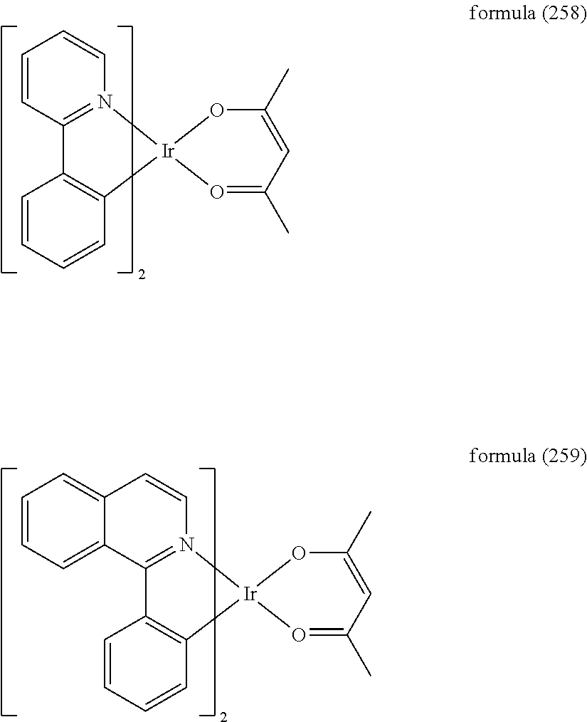

in which A is selected from the group consisting of linear or branched alkylene, cycloalkylene, alkylsilylene, silylene, arylsilylene, alkylalkoxyalkylene, arylalkoxyalkylene, alkylthioalkylene, sulfone, alkylene sulfone, sulfone oxide, alkylene sulfone oxide, where the alkylene group in each case has, independently of one another, 1 to 12 C atoms and where one or more H atoms may be replaced by F, Cl, Br, I, alkyl, heteroalkyl, cycloalkyl, aryl or heteroaryl.


where Ar1, Ar2 and Ar3 each, independently of one another, denote an aromatic or heteroaromatic group having 5 to 60 ring atoms, R1, R2, R3, and R4 each, independently of one another, denote alkyl(ene), cycloalkyl(ene), alkylsilyl(ene), silyl(ene), arylsilyl(ene), alkylalkoxyalkyl(ene), arylalkoxyalkyl(ene), alkylthioalkyl(ene), phosphine, phosphine oxide, sulfone, alkylene sulfone, sulfone oxide, alkylene sulfone oxide, where the alkyl(ene) group in each case has, independently of one another, 1 to 12 C atoms and where one or more H atoms may be replaced by F, Cl, Br, I, alkyl, heteroalkyl, cycloalkyl, an aryl or heteroaryl group.


where the symbols and indices have the meaning indicated in the case of structures (265) to (279).


in which E is the emitting unit, FG is a functional group selected from a host or matrix material unit, a further emitting unit, a charge-transport unit and an electron-transport unit, x is greater than zero and x+y is equal to 1. The groups FG in the various recurring units of the formula (297) in the polymer may have different meanings. It is particularly preferred for all functional groups mentioned above to be present in the polymer.


butadiene derivatives (U.S. Pat. No. 4,356,429), heterocyclic optical brighteners (U.S. Pat. No. 4,539,507), benzimidazole derivatives (US 2007/0273272 A1), such as, for example, TPBI (U.S. Pat. No. 5,766,779),

1,3,5-triazines, for example spirobifluorenetriazine derivatives (for example in accordance with the unpublished application DE 102008064200.2) pyrenes, anthracenes, tetracenes, fluorenes, spirofluorenes, dendrimers, tetracenes (for example rubrene derivatives), 1,10-phenanthroline derivatives (JP 2003-115387, JP 2004-311184, JP-2001-267080, WO 2002-043449), silacyclopentadiene derivatives (EP 1480280, EP 1478032, EP 1469533), borane derivatives, such as, for example, triarylborane derivatives with Si,

pyridine derivatives (JP 2004-200162), phenanthrolines, especially 1,10-phenanthroline derivatives, such as, for example, BCP and Bphen, also a plurality of phenanthrolines connected via biphenyl or other aromatic groups (US 2007/0252517 A1) or phenanthrolines connected to anthracene (US 2007/0122656 A1).


1,3,4-oxadiazoles, for example


*


*


where D is a functional group, preferably selected, from HTM, HIM, ETM, EIM, host, phosphorescent emitter or fluorescent emitter; and o is the recurring numbers of the unit, and a natural number of greater than or equal to 3, preferably greater than or equal to 10, particularly preferably greater than or equal to 20;

- Group 1: units which enhance the hole-injection and/or hole-transport properties of the polymers;
- Group 2: units which enhance the electron-injection and/or electron-transport properties of the polymers;
- Group 3: units which have combinations of individual units from group 1 and group 2;
- Group 4: units which modify the emission characteristics to such an extent that electrophosphorescence can be obtained instead of electrofluorescence;
- Group 5: units which improve the transfer from the so-called singlet
- state to the triplet state;
- Group 6: units which influence the emission colour of the resultant polymers;
- Group 7: units which are typically used as backbone;
- Group 8: units which influence the film-morphological and/or the rheological properties of the resultant polymers.


| TABLE 1 |
| Composition of the polymers in mol % |
| Polymer | M1 | M2 | M3 | M4 | M5 | M6 |
| P1 | 40 | 40 | 0 | 20 | 0 | 0 |
| P2 | 40 | 35 | 0 | 20 | 5 | 0 |
| P3 | 40 | 35 | 0 | 20 | 0 | 5 |
| P4 | 35 | 35 | 0 | 20 | 5 | 5 |
| P5 | 0 | 40 | 40 | 20 | 0 | 0 |
| P6 | 0 | 35 | 40 | 20 | 5 | 0 |
| P7 | 0 | 35 | 40 | 20 | 0 | 5 |
| P8 | 0 | 35 | 35 | 20 | 5 | 5 |
| TABLE 2 |
| Molecular weights and yield of the polymers |
| Polymer | Mn [gmol−1] | Mw [gmol−1] | PD | Yield | ||
| P1 | 47.000 | 15.400 | 3.05 | 48% | ||
| P2 | 133.000 | 49.300 | 2.70 | 61% | ||
| P3 | 125.000 | 82.700 | 1.51 | 58% | ||
| P4 | 123.000 | 71.200 | 1.73 | 58% | ||
| P5 | 66.200 | 28.600 | 2.31 | 53% | ||
| P6 | 76.800 | 39.300 | 2.95 | 55% | ||
| P7 | 153.000 | 88.300 | 1.73 | 63% | ||
| P8 | 105.200 | 62.700 | 1.68 | 55% | ||


| TABLE 3 |
| Composition of the polymers in mol % |
| Polymer | S1 | S2 | S3 | S4 | S5 | S6 | S7 | S8 | S9 |
| P9 | 10 | 0 | 20 | 20 | 50 | 0 | 0 | 0 | 0 |
| P10 | 10 | 0 | 15 | 20 | 50 | 0 | 0 | 5 | 0 |
| P11 | 10 | 0 | 15 | 20 | 50 | 0 | 0 | 0 | 5 |
| P12 | 10 | 0 | 15 | 15 | 50 | 0 | 0 | 5 | 5 |
| P13 | 10 | 0 | 20 | 20 | 0 | 50 | 0 | 0 | 0 |
| P14 | 10 | 0 | 15 | 20 | 0 | 50 | 0 | 5 | 0 |
| P15 | 10 | 0 | 15 | 20 | 0 | 50 | 0 | 0 | 5 |
| P16 | 10 | 0 | 15 | 15 | 0 | 50 | 0 | 5 | 5 |
| P17 | 10 | 0 | 15 | 20 | 0 | 0 | 50 | 5 | 0 |
| P18 | 10 | 0 | 15 | 20 | 0 | 0 | 50 | 0 | 5 |
| P19 | 10 | 20 | 15 | 0 | 50 | 0 | 0 | 5 | 0 |
| P20 | 10 | 20 | 15 | 0 | 50 | 0 | 0 | 0 | 5 |
| TABLE 4 |
| The EML compositions in various OLEDs |
| EML compositions | Concentration | ||
| Device | [wt %] | Solvent | [g/l] |
| OLED1 | 90% P1:5% E1:5% E2 | Toluene | 10 |
| OLED2 | 95% P2:5% E2 | Toluene | 10 |
| OLED3 | 95% P3:5% E1 | Toluene | 10 |
| OLED4 | 100% P4 | Toluene | 10 |
| OLED5 | 90% P5:5% E1:5% E2 | Toluene | 10 |
| OLED6 | 95% P6:5% E2 | Toluene | 10 |
| OLED7 | 95% P7:5% E1 | Toluene | 10 |
| OLED8 | 100% P8 | Toluene | 10 |
| OLED9 | 90% P9:5% E1:5% E2 | Toluene | 10 |
| OLED10 | 95% P10:5% E2 | Toluene | 10 |
| OLED11 | 95% P11:5% E1 | Toluene | 10 |
| OLED12 | 100% P12 | Toluene | 10 |
| OLED13 | 90% P13:5% E1:5% E2 | Toluene | 10 |
| OLED14 | 95% P14:5% E2 | Toluene | 10 |
| OLED15 | 95% P15:5% E1 | Toluene | 10 |
| OLED16 | 100% P16 | Toluene | 10 |
| OLED17 | 95% P17:5% E2 | Toluene | 10 |
| OLED18 | 95% P18:5% E1 | Toluene | 10 |
| OLED19 | 95% P19:5% E2 | Toluene | 10 |
| OLED20 | 95% P20:5% E1 | Toluene | 10 |
| TABLE 5 |
| Device results of the devices according to the invention and comparison |
| thereof |
| Device | CIE [x:y] | U [V] @ 100 nits | Max. eff. [cd/A] | EQE [%] |
| OLED1 | 0.68:0.32 | 5.8 | 5.1 | 7.6% |
| OLED2 | 0.68:0.32 | 5.4 | 7.2 | 10.7% |
| OLED3 | 0.68:0.31 | 5.5 | 6.6 | 9.1% |
| OLED4 | 0.67:0.32 | 5.2 | 8.5 | 9.8% |
| OLED5 | 0.68:0.32 | 5.2 | 5.7 | 8.7% |
| OLED6 | 0.68:0.32 | 5.1 | 6.7 | 10.0% |
| OLED7 | 0.67:0.32 | 5.2 | 7.5 | 8.6% |
| OLED8 | 0.68:0.31 | 4.9 | 6.6 | 9.3% |
| OLED9 | 0.68:0.32 | 5.8 | 5.4 | 8.3% |
| OLED10 | 0.68:0.32 | 5.5 | 8.6 | 9.7% |
| OLED11 | 0.68:0.31 | 5.6 | 7.5 | 10.4% |
| OLED12 | 0.67:0.31 | 5.4 | 7.4 | 9.8% |
| OLED13 | 0.68:0.32 | 6.1 | 4.4 | 6.6% |
| OLED14 | 0.67:0.32 | 5.6 | 7.4 | 8.5% |
| OLED15 | 0.68:0.33 | 5.7 | 6.8 | 11.6% |
| OLED16 | 0.67:0.33 | 5.4 | 9.6 | 10.7% |
| OLED17 | 0.68:0.32 | 6.1 | 5.8 | 8.9% |
| OLED18 | 0.67:0.32 | 6.2 | 6.1 | 7.0% |
| OLED19 | 0.68:0.32 | 5.3 | 6.1 | 9.3% |
| OLED20 | 0.67:0.31 | 5.1 | 7.1 | 9.4% |

are synthesised in accordance with the following general procedures, where D can be different functional groups.
| TABLE 6 |
| Composition of the polymers in mol % |
| Polymer | M1 | M2 | M3 | M4 | M7 | Ethylene oxide |
| P21 | 80 | 20 | ||||
| P22 | 40 | 40 | 20 | |||
| P23 | 80 | 20 | ||||
| P24 | 80 | 20 | ||||
| P25 | 80 | 20 | ||||
| TABLE 7 |
| Molecular weights and yield of the polymers |
| Polymer | Mn [gmol−1] | Mw [gmol−1] | PD | Yield | ||
| P21 | 47.000 | 15.400 | 1.05 | 48% | ||
| P22 | 133.000 | 49.300 | 1.37 | 61% | ||
| P23 | 125.000 | 82.700 | 1.31 | 58% | ||
| P24 | 123.000 | 71.200 | 1.34 | 58% | ||
| P25 | 66.200 | 28.600 | 1.12 | 53% | ||

| TABLE 8 |
| The EML compositions in various OLECs |
| EML | |||
| Device | compositions [wt %] | Solvent | Concentration [g/l] |
| OLEC1 | P21:20% E1:2.5% LiTrf | cyclohexanone | 10 |
| OLEC2 | P22:20% E1:2.5% LiTrf | cyclohexanone | 10 |
| OLEC3 | P23:20% E1:2.5% LiTrf | cyclohexanone | 10 |
| OLEC4 | P25:7% E3:2.5% LiTrf | cyclohexanone | 10 |
| TABLE 9 |
| Device results of the devices according to the invention and comparison |
| thereof |
| Device | CIE [x:y] | U [V] @ 100 nits | Max. eff. [cd/A] | EQE [%] |
| OLEC1 | 0.32:0.63 | 3.2 | 12.97 | 3.6% |
| OLEC2 | 0.31:0.63 | 3.4 | 10.01 | 2.8% |
| OLEC3 | 0.32:0.62 | 3.1 | 15.16 | 4.3% |
| OLEC4 | 0.14:0.18 | 3.7 | 2.34 | 1.9% |
Claims (24)


Applications Claiming Priority (4)
| Application Number | Priority Date | Filing Date | Title |
|---|---|---|---|
| DE102010055901.6 | 2010-12-23 | ||
| DE102010055901 | 2010-12-23 | ||
| DE102010055901A DE102010055901A1 (en) | 2010-12-23 | 2010-12-23 | Organic electroluminescent device |
| PCT/EP2011/005916 WO2012084114A1 (en) | 2010-12-23 | 2011-11-24 | Organic electroluminescent device |
Publications (2)
| Publication Number | Publication Date |
|---|---|
| US20130277617A1 US20130277617A1 (en) | 2013-10-24 |
| US9478762B2 true US9478762B2 (en) | 2016-10-25 |
Family
ID=45044512
Family Applications (1)
| Application Number | Title | Priority Date | Filing Date |
|---|---|---|---|
| US13/996,066 Active 2032-02-13 US9478762B2 (en) | 2010-12-23 | 2011-11-24 | Organic electroluminescent device |
Country Status (4)
| Country | Link |
|---|---|
| US (1) | US9478762B2 (en) |
| JP (2) | JP6258036B2 (en) |
| DE (2) | DE102010055901A1 (en) |
| WO (1) | WO2012084114A1 (en) |
Families Citing this family (12)
| Publication number | Priority date | Publication date | Assignee | Title |
|---|---|---|---|---|
| DE102010055901A1 (en) * | 2010-12-23 | 2012-06-28 | Merck Patent Gmbh | Organic electroluminescent device |
| GB201122316D0 (en) * | 2011-12-23 | 2012-02-01 | Cambridge Display Tech Ltd | Polymer, polymer composition and organic light-emitting device |
| JP5867650B2 (en) * | 2013-07-17 | 2016-02-24 | 住友化学株式会社 | Composition and light emitting device using the same |
| US20160181537A1 (en) * | 2013-07-29 | 2016-06-23 | Merck Patent Gmbh | Electroluminescence Device |
| US9231217B2 (en) * | 2013-11-28 | 2016-01-05 | Semiconductor Energy Laboratory Co., Ltd. | Synthesis method of organometallic complex, synthesis method of pyrazine derivative, 5,6-diaryl-2-pyrazyl triflate, light-emitting element, light-emitting device, electronic device, and lighting device |
| JP6323093B2 (en) * | 2014-03-17 | 2018-05-16 | 住友化学株式会社 | Polymer compound and light emitting device using the same |
| JP6303658B2 (en) * | 2014-03-17 | 2018-04-04 | 住友化学株式会社 | Polymer compound and light emitting device using the same |
| WO2018192436A1 (en) * | 2017-04-19 | 2018-10-25 | The University Of Hong Kong | Dendrimers containing luminescent platinum(ii) compounds for organic light-emitting devices and their preparation |
| CN107170911B (en) * | 2017-06-23 | 2019-01-04 | 深圳市华星光电技术有限公司 | A kind of aging testing system and method for display panel |
| JP2020109149A (en) * | 2018-12-28 | 2020-07-16 | 三星電子株式会社Samsung Electronics Co.,Ltd. | Arylamine polymer including silicone, and electroluminescence device material and electroluminescence device using polymer |
| WO2021125011A1 (en) * | 2019-12-16 | 2021-06-24 | 三菱ケミカル株式会社 | Polymer, composition for organic electroluminescent element, composition for forming hole transport layer or hole injection layer, organic electroluminescent element, organic el display device, and organic el illuminator |
| CN115161014B (en) * | 2022-06-09 | 2023-04-07 | 昆明理工大学 | Preparation method and application of doped room temperature phosphorescent waterborne polymer anti-counterfeiting material |
Citations (31)
| Publication number | Priority date | Publication date | Assignee | Title |
|---|---|---|---|---|
| US20030091862A1 (en) * | 2001-08-31 | 2003-05-15 | Nippon Hoso Kyokai | Phosphorescent compound, a phosphorescent composition and an organic light-emitting device |
| JP2005015508A (en) | 2003-06-23 | 2005-01-20 | Konica Minolta Holdings Inc | Block copolymer, organic electroluminescent element, display device, illuminator and light source |
| US20060093852A1 (en) * | 2002-06-04 | 2006-05-04 | Dirk Marsitzky | Phosphorescent and luminescent conjugated polymers and their use in electroluminescent assemblies |
| US20060105201A1 (en) * | 2004-11-12 | 2006-05-18 | Jun-Yeob Lee | Organic electroluminescent device |
| US20060149022A1 (en) * | 2003-02-06 | 2006-07-06 | Amir Parham | Conjugated polymers and blends containing carbazole, representation and use thereof |
| US20060199943A1 (en) * | 2003-09-20 | 2006-09-07 | Ovion Organic Semiconductors Gmbh | White-emitting copolymers, representation and use thereof |
| US20060208221A1 (en) * | 2003-04-15 | 2006-09-21 | Covion Organic Semiconductors Gmbh | Mixtures of matrix materials and organic semiconductors capable of emission, use of the same and electronic components containing said mixtures |
| US20070015006A1 (en) * | 2005-07-15 | 2007-01-18 | Lee Jun Y | White organic light emitting diode |
| JP2007059939A (en) | 2001-08-31 | 2007-03-08 | Nippon Hoso Kyokai <Nhk> | Organic light emitting device and display unit |
| JP2007070619A (en) | 2005-08-12 | 2007-03-22 | Sumitomo Chemical Co Ltd | Polymer material and element using the same |
| US20070231598A1 (en) * | 2004-05-11 | 2007-10-04 | Merck Patent Gmbh Patent & Scientific Information | Electroluminescent Polymers |
| US20070247061A1 (en) * | 2006-04-20 | 2007-10-25 | Vadim Adamovich | Multiple dopant emissive layer OLEDs |
| US20070281182A1 (en) * | 2004-07-06 | 2007-12-06 | Niels Schulte | Electroluminescent Polymers |
| US20080102312A1 (en) * | 2004-04-26 | 2008-05-01 | Merck Patent Gmbh | Electroluminescent Polymers Containing Planar Arylamine Units, the Preparation and Use Thereof |
| US20080103279A1 (en) * | 2004-07-15 | 2008-05-01 | Merck Patent Gmbh | Use of Polymers for Up-Conversion, and Devices for Up-Conversion |
| US20080169756A1 (en) * | 2007-01-17 | 2008-07-17 | Son Jhun-Mo | Light emitting polymer comprising phosphorescence unit and fluorescence unit and organic light emitting device comprising the light emitting polymer |
| US20090167166A1 (en) * | 2006-05-31 | 2009-07-02 | Merck Patent Gmbh | Materials for organic electroluminescent devices |
| WO2009093033A1 (en) | 2008-01-23 | 2009-07-30 | Cambridge Display Technology Limited | White light emitting material |
| US20100033082A1 (en) * | 2008-08-07 | 2010-02-11 | General Electric Company | Method of Manufacture of a Multi-Layer Phosphorescent Organic Light Emitting Device, and Articles Thereof |
| WO2010015306A1 (en) * | 2008-08-08 | 2010-02-11 | Merck Patent Gmbh, | Organic electroluminescence device |
| US20130099171A1 (en) * | 2010-06-24 | 2013-04-25 | Merck Patent Gmbh | Materials for organic electroluminescent devices |
| US8610110B2 (en) * | 2008-03-11 | 2013-12-17 | Merck Patent Gmbh | Optoelectronic component comprising neutral transition metal complexes |
| US9281483B2 (en) * | 2006-02-10 | 2016-03-08 | Universal Display Corporation | Organic electroluminescent materials and devices |
| US20160072082A1 (en) * | 2014-05-08 | 2016-03-10 | Universal Display Corporation | Organic electroluminescent materials and devices |
| US9287519B2 (en) * | 2012-03-19 | 2016-03-15 | Osram Oled Gmbh | Optoelectronic device and method for producing an optoelectronic device |
| US20160126486A1 (en) * | 2013-05-24 | 2016-05-05 | Osram Oled Gmbh | Process for producing an optoelectronic component and optoelectronic component |
| US9334260B2 (en) * | 2009-11-14 | 2016-05-10 | Merck Patent Gmbh | Materials for electronic devices |
| US9349954B2 (en) * | 2007-11-09 | 2016-05-24 | Universal Display Corporation | Stable blue phosphorescent organic light emitting devices |
| US9349960B2 (en) * | 2009-05-29 | 2016-05-24 | Merck Patent Gmbh | Compounds and polymers which contain substituted indenofluorene derivatives as structural unit, process for the preparation thereof, and the use thereof as electronic devices and mixtures and solutions |
| US20160149158A1 (en) * | 2013-06-25 | 2016-05-26 | Osram Oled Gmbh | Method for processing an electronic component and electronic component arrangement |
| US9356245B2 (en) * | 2004-05-18 | 2016-05-31 | Universal Display Corporation | Carbene metal complexes as OLED materials |
Family Cites Families (138)
| Publication number | Priority date | Publication date | Assignee | Title |
|---|---|---|---|---|
| NL250330A (en) | 1959-04-09 | |||
| US3526501A (en) | 1967-02-03 | 1970-09-01 | Eastman Kodak Co | 4-diarylamino-substituted chalcone containing photoconductive compositions for use in electrophotography |
| US3567450A (en) | 1968-02-20 | 1971-03-02 | Eastman Kodak Co | Photoconductive elements containing substituted triarylamine photoconductors |
| US3658520A (en) | 1968-02-20 | 1972-04-25 | Eastman Kodak Co | Photoconductive elements containing as photoconductors triarylamines substituted by active hydrogen-containing groups |
| US3615404A (en) | 1968-04-25 | 1971-10-26 | Scott Paper Co | 1 3-phenylenediamine containing photoconductive materials |
| US3717462A (en) | 1969-07-28 | 1973-02-20 | Canon Kk | Heat treatment of an electrophotographic photosensitive member |
| BE756943A (en) | 1969-10-01 | 1971-03-16 | Eastman Kodak Co | NEW PHOTOCONDUCTIVE COMPOSITIONS AND PRODUCTS CONTAINING THEM, USED IN PARTICULAR IN ELECTROPHOTOGRAPHY |
| US4127412A (en) | 1975-12-09 | 1978-11-28 | Eastman Kodak Company | Photoconductive compositions and elements |
| JPS54110837A (en) | 1978-02-17 | 1979-08-30 | Ricoh Co Ltd | Electrophotographic photoreceptor |
| US4209115A (en) | 1978-09-06 | 1980-06-24 | Georg Menshen & Co. Kg | Two-part delivery outlet closure for containers |
| JPS5646234A (en) | 1979-09-21 | 1981-04-27 | Ricoh Co Ltd | Electrophotographic receptor |
| US4356429A (en) | 1980-07-17 | 1982-10-26 | Eastman Kodak Company | Organic electroluminescent cell |
| US4539507A (en) | 1983-03-25 | 1985-09-03 | Eastman Kodak Company | Organic electroluminescent devices having improved power conversion efficiencies |
| JPS61210363A (en) | 1985-03-15 | 1986-09-18 | Canon Inc | Electrophotographic sensitive body |
| US4720432A (en) | 1987-02-11 | 1988-01-19 | Eastman Kodak Company | Electroluminescent device with organic luminescent medium |
| US4769292A (en) | 1987-03-02 | 1988-09-06 | Eastman Kodak Company | Electroluminescent device with modified thin film luminescent zone |
| JPH07108950B2 (en) | 1987-05-27 | 1995-11-22 | ダイセル・ヒュルス株式会社 | Polyamide resin composition |
| US5121029A (en) | 1987-12-11 | 1992-06-09 | Idemitsu Kosan Co., Ltd. | Electroluminescence device having an organic electroluminescent element |
| JPH01211399A (en) | 1988-02-19 | 1989-08-24 | Toshiba Corp | Dynamic shift register with scanning function |
| JPH02282263A (en) | 1988-12-09 | 1990-11-19 | Nippon Oil Co Ltd | Hole transferring material |
| JP2727620B2 (en) | 1989-02-01 | 1998-03-11 | 日本電気株式会社 | Organic thin film EL device |
| US5130603A (en) | 1989-03-20 | 1992-07-14 | Idemitsu Kosan Co., Ltd. | Organic electroluminescence device |
| GB8909011D0 (en) | 1989-04-20 | 1989-06-07 | Friend Richard H | Electroluminescent devices |
| US4950950A (en) | 1989-05-18 | 1990-08-21 | Eastman Kodak Company | Electroluminescent device with silazane-containing luminescent zone |
| US5061569A (en) | 1990-07-26 | 1991-10-29 | Eastman Kodak Company | Electroluminescent device with organic electroluminescent medium |
| JP3016896B2 (en) | 1991-04-08 | 2000-03-06 | パイオニア株式会社 | Organic electroluminescence device |
| JPH061973A (en) | 1992-06-18 | 1994-01-11 | Konica Corp | Organic electroluminescent element |
| US5529853A (en) | 1993-03-17 | 1996-06-25 | Sanyo Electric Co., Ltd. | Organic electroluminescent element |
| JPH07133483A (en) | 1993-11-09 | 1995-05-23 | Shinko Electric Ind Co Ltd | Organic luminescent material for el element and el element |
| JP2686418B2 (en) | 1994-08-12 | 1997-12-08 | 東洋インキ製造株式会社 | Diarylamine derivative, production method and use thereof |
| JP3306735B2 (en) | 1995-01-19 | 2002-07-24 | 出光興産株式会社 | Organic electroluminescent device and organic thin film |
| EP0765106B1 (en) | 1995-09-25 | 2002-11-27 | Toyo Ink Manufacturing Co., Ltd. | Light-emitting material for organic electroluminescence device, and organic electroluminescence device for which the light-emitting material is adapted |
| US5766779A (en) | 1996-08-20 | 1998-06-16 | Eastman Kodak Company | Electron transporting materials for organic electroluminescent devices |
| JP3654909B2 (en) | 1996-12-28 | 2005-06-02 | Tdk株式会社 | Organic EL device |
| WO2000007065A1 (en) | 1998-07-29 | 2000-02-10 | Matsushita Electric Industrial Co., Ltd. | Scattering display and method for driving the same |
| EP1029909A4 (en) | 1998-09-09 | 2007-01-10 | Idemitsu Kosan Co | Organic electroluminescence device and phenylenediamine derivative |
| US6208077B1 (en) | 1998-11-05 | 2001-03-27 | Eastman Kodak Company | Organic electroluminescent device with a non-conductive fluorocarbon polymer layer |
| US6208075B1 (en) | 1998-11-05 | 2001-03-27 | Eastman Kodak Company | Conductive fluorocarbon polymer and method of making same |
| US6361886B2 (en) | 1998-12-09 | 2002-03-26 | Eastman Kodak Company | Electroluminescent device with improved hole transport layer |
| US6020078A (en) | 1998-12-18 | 2000-02-01 | Eastman Kodak Company | Green organic electroluminescent devices |
| US6127004A (en) | 1999-01-29 | 2000-10-03 | Eastman Kodak Company | Forming an amorphous fluorocarbon layer in electroluminescent devices |
| EP2278637B2 (en) | 1999-12-01 | 2021-06-09 | The Trustees of Princeton University | Complexes of form L2MX |
| JP4876311B2 (en) | 2000-01-14 | 2012-02-15 | 東レ株式会社 | Light emitting element |
| US6660410B2 (en) | 2000-03-27 | 2003-12-09 | Idemitsu Kosan Co., Ltd. | Organic electroluminescence element |
| US20020121638A1 (en) | 2000-06-30 | 2002-09-05 | Vladimir Grushin | Electroluminescent iridium compounds with fluorinated phenylpyridines, phenylpyrimidines, and phenylquinolines and devices made with such compounds |
| EP1325671B1 (en) | 2000-08-11 | 2012-10-24 | The Trustees Of Princeton University | Organometallic compounds and emission-shifting organic electrophosphorescence |
| US6538375B1 (en) | 2000-08-17 | 2003-03-25 | General Electric Company | Oled fiber light source |
| JP4154139B2 (en) | 2000-09-26 | 2008-09-24 | キヤノン株式会社 | Light emitting element |
| JP4154138B2 (en) | 2000-09-26 | 2008-09-24 | キヤノン株式会社 | Light emitting element, display device and metal coordination compound |
| JP4154140B2 (en) | 2000-09-26 | 2008-09-24 | キヤノン株式会社 | Metal coordination compounds |
| US6893743B2 (en) | 2000-10-04 | 2005-05-17 | Mitsubishi Chemical Corporation | Organic electroluminescent device |
| EP2365735B1 (en) | 2000-11-24 | 2013-08-28 | Toray Industries Inc. | Luminescent element material and luminescent element comprising the same |
| DE10109027A1 (en) | 2001-02-24 | 2002-09-05 | Covion Organic Semiconductors | Rhodium and iridium complexes |
| JP4438042B2 (en) | 2001-03-08 | 2010-03-24 | キヤノン株式会社 | Metal coordination compound, electroluminescent element and display device |
| KR20030093240A (en) | 2001-03-16 | 2003-12-06 | 이데미쓰 고산 가부시키가이샤 | Method for producing aromatic amino compound |
| JP4259875B2 (en) | 2001-03-24 | 2009-04-30 | メルク パテント ゲーエムベーハー | Conjugated polymers containing spirobifluorene units and fluorene units and uses thereof |
| DE10116962A1 (en) | 2001-04-05 | 2002-10-10 | Covion Organic Semiconductors | Rhodium and iridium complexes |
| JP2003115387A (en) | 2001-10-04 | 2003-04-18 | Junji Kido | Organic light emitting element and its manufacturing method |
| US6835469B2 (en) | 2001-10-17 | 2004-12-28 | The University Of Southern California | Phosphorescent compounds and devices comprising the same |
| US6753096B2 (en) | 2001-11-27 | 2004-06-22 | General Electric Company | Environmentally-stable organic electroluminescent fibers |
| DE10159946A1 (en) | 2001-12-06 | 2003-06-18 | Covion Organic Semiconductors | Process for the production of aryl-aryl coupled compounds |
| JP4256182B2 (en) | 2002-03-14 | 2009-04-22 | Tdk株式会社 | Organic EL device |
| JP4316387B2 (en) | 2002-03-22 | 2009-08-19 | 出光興産株式会社 | Material for organic electroluminescence device and organic electroluminescence device using the same |
| US20030230980A1 (en) | 2002-06-18 | 2003-12-18 | Forrest Stephen R | Very low voltage, high efficiency phosphorescent oled in a p-i-n structure |
| DE10238903A1 (en) | 2002-08-24 | 2004-03-04 | Covion Organic Semiconductors Gmbh | New heteroaromatic rhodium and iridium complexes, useful in electroluminescent and/or phosphorescent devices as the emission layer and for use in solar cells, photovoltaic devices and organic photodetectors |
| DE10249723A1 (en) | 2002-10-25 | 2004-05-06 | Covion Organic Semiconductors Gmbh | Conjugated polymers containing arylamine units, their preparation and use |
| JP4287198B2 (en) | 2002-11-18 | 2009-07-01 | 出光興産株式会社 | Organic electroluminescence device |
| JP2004200162A (en) | 2002-12-05 | 2004-07-15 | Toray Ind Inc | Light emitting element |
| JP4411851B2 (en) | 2003-03-19 | 2010-02-10 | コニカミノルタホールディングス株式会社 | Organic electroluminescence device |
| JP2004311184A (en) | 2003-04-04 | 2004-11-04 | Junji Kido | Electron transportation material formed of multinucleate phenanthroline derivative, charge control material, and organic luminescent element using them |
| WO2004092111A1 (en) | 2003-04-10 | 2004-10-28 | Idemitsu Kosan Co., Ltd. | Aromatic amine derivative and organic electroluminescent element employing the same |
| KR20040089567A (en) | 2003-04-14 | 2004-10-21 | 가부시키가이샤 도요다 지도숏키 | Organic electroluminescent element that suppresses generation of ultraviolet light and lighting system that has organic electroluminescent element |
| US20040209116A1 (en) | 2003-04-21 | 2004-10-21 | Xiaofan Ren | Organic light emitting devices with wide gap host materials |
| US20040209115A1 (en) | 2003-04-21 | 2004-10-21 | Thompson Mark E. | Organic light emitting devices with wide gap host materials |
| EP1617711B1 (en) | 2003-04-23 | 2016-08-17 | Konica Minolta Holdings, Inc. | Organic electroluminescent device and display |
| US7122958B2 (en) | 2003-05-16 | 2006-10-17 | Kabushiki Kaisha Toyota Jidoshokki | Light-emitting apparatus and method for forming the same |
| JP4752192B2 (en) * | 2003-05-16 | 2011-08-17 | 住友化学株式会社 | Composition and polymer light emitting device |
| JP2004349138A (en) | 2003-05-23 | 2004-12-09 | Toyota Industries Corp | Organic electroluminescent element and its manufacturing method |
| DE10328627A1 (en) | 2003-06-26 | 2005-02-17 | Covion Organic Semiconductors Gmbh | New materials for electroluminescence |
| JP4773346B2 (en) | 2003-07-07 | 2011-09-14 | メルク パテント ゲーエムベーハー | Mixtures of organic light emitting semiconductors and matrix materials, their use and electronic components comprising said materials. |
| DE10333232A1 (en) | 2003-07-21 | 2007-10-11 | Merck Patent Gmbh | Organic electroluminescent element |
| DE10337346A1 (en) | 2003-08-12 | 2005-03-31 | Covion Organic Semiconductors Gmbh | Conjugated polymers containing dihydrophenanthrene units and their use |
| JP2005108556A (en) | 2003-09-29 | 2005-04-21 | Tdk Corp | Organic el element and organic el display |
| DE10345572A1 (en) | 2003-09-29 | 2005-05-19 | Covion Organic Semiconductors Gmbh | metal complexes |
| US7795801B2 (en) | 2003-09-30 | 2010-09-14 | Konica Minolta Holdings, Inc. | Organic electroluminescent element, illuminator, display and compound |
| US7830085B2 (en) * | 2003-10-06 | 2010-11-09 | The Regents Of The University Of California | White electrophosphorescence from semiconducting polymer blends |
| WO2005040302A1 (en) | 2003-10-22 | 2005-05-06 | Merck Patent Gmbh | New materials for electroluminescence and the utilization thereof |
| DE10350606A1 (en) | 2003-10-30 | 2005-06-09 | Covion Organic Semiconductors Gmbh | Process for the preparation of heteroleptic, ortho-metallated organometallic compounds |
| JP4321808B2 (en) * | 2003-11-11 | 2009-08-26 | 大日本印刷株式会社 | Organic electroluminescence device and display panel |
| DE602004028399D1 (en) | 2003-11-28 | 2010-09-09 | Merck Patent Gmbh | ORGANIC SEMICONDUCTOR LAYER FORMULATIONS WITH POLYACENES AND ORGANIC BINDER POLYMERS |
| ATE504639T1 (en) | 2003-12-26 | 2011-04-15 | Idemitsu Kosan Co | MATERIAL FOR ORGANIC ELECTROLUMINESCENCE DEVICE AND ORGANIC ELECTROLUMINESCENCE DEVICE BASED THEREOF |
| JP4466160B2 (en) | 2004-03-30 | 2010-05-26 | Tdk株式会社 | Organic EL element and organic EL display |
| US7790890B2 (en) | 2004-03-31 | 2010-09-07 | Konica Minolta Holdings, Inc. | Organic electroluminescence element material, organic electroluminescence element, display device and illumination device |
| DE102004023277A1 (en) | 2004-05-11 | 2005-12-01 | Covion Organic Semiconductors Gmbh | New material mixtures for electroluminescence |
| TWI327563B (en) | 2004-05-24 | 2010-07-21 | Au Optronics Corp | Anthracene compound and organic electroluminescent device including the anthracene compound |
| JP4862248B2 (en) | 2004-06-04 | 2012-01-25 | コニカミノルタホールディングス株式会社 | Organic electroluminescence element, lighting device and display device |
| CN100368363C (en) | 2004-06-04 | 2008-02-13 | 友达光电股份有限公司 | Anthracene compound and organic electroluminescent apparatus containing it |
| TW200613515A (en) | 2004-06-26 | 2006-05-01 | Merck Patent Gmbh | Compounds for organic electronic devices |
| DE102004031000A1 (en) | 2004-06-26 | 2006-01-12 | Covion Organic Semiconductors Gmbh | Organic electroluminescent devices |
| TW200639140A (en) | 2004-12-01 | 2006-11-16 | Merck Patent Gmbh | Compounds for organic electronic devices |
| JP4263700B2 (en) | 2005-03-15 | 2009-05-13 | 出光興産株式会社 | Aromatic amine derivative and organic electroluminescence device using the same |
| US20060222886A1 (en) | 2005-04-04 | 2006-10-05 | Raymond Kwong | Arylpyrene compounds |
| US8674141B2 (en) | 2005-05-03 | 2014-03-18 | Merck Patent Gmbh | Organic electroluminescent device and boric acid and borinic acid derivatives used therein |
| DE102005023437A1 (en) | 2005-05-20 | 2006-11-30 | Merck Patent Gmbh | Connections for organic electronic devices |
| TWI415920B (en) * | 2005-08-12 | 2013-11-21 | Sumitomo Chemical Co | High molecular weight material and element using such material |
| US7588839B2 (en) | 2005-10-19 | 2009-09-15 | Eastman Kodak Company | Electroluminescent device |
| US20070092753A1 (en) | 2005-10-26 | 2007-04-26 | Eastman Kodak Company | Organic element for low voltage electroluminescent devices |
| US20070092755A1 (en) | 2005-10-26 | 2007-04-26 | Eastman Kodak Company | Organic element for low voltage electroluminescent devices |
| US7553558B2 (en) | 2005-11-30 | 2009-06-30 | Eastman Kodak Company | Electroluminescent device containing an anthracene derivative |
| JP4593631B2 (en) | 2005-12-01 | 2010-12-08 | 新日鐵化学株式会社 | Compound for organic electroluminescence device and organic electroluminescence device |
| DE102005058543A1 (en) | 2005-12-08 | 2007-06-14 | Merck Patent Gmbh | Organic electroluminescent devices |
| DE102005058557A1 (en) | 2005-12-08 | 2007-06-14 | Merck Patent Gmbh | Organic electroluminescent device |
| US7709105B2 (en) | 2005-12-14 | 2010-05-04 | Global Oled Technology Llc | Electroluminescent host material |
| JP4879591B2 (en) | 2006-01-26 | 2012-02-22 | 昭和電工株式会社 | Polymer light-emitting material, organic electroluminescence element, and display device |
| DE102006015183A1 (en) | 2006-04-01 | 2007-10-04 | Merck Patent Gmbh | New benzocycloheptene compound useful in organic electronic devices e.g. organic electroluminescent device, polymer electroluminescent device and organic field-effect-transistors |
| JP4995475B2 (en) | 2006-04-03 | 2012-08-08 | 出光興産株式会社 | Benzanthracene derivative and organic electroluminescence device using the same |
| US20070252517A1 (en) | 2006-04-27 | 2007-11-01 | Eastman Kodak Company | Electroluminescent device including an anthracene derivative |
| WO2007133632A2 (en) * | 2006-05-09 | 2007-11-22 | University Of Washington | Large-bandgap host materials for phosphorescent emitters |
| DE102006025846A1 (en) | 2006-06-02 | 2007-12-06 | Merck Patent Gmbh | New materials for organic electroluminescent devices |
| DE102006031990A1 (en) | 2006-07-11 | 2008-01-17 | Merck Patent Gmbh | New materials for organic electroluminescent devices |
| JPWO2008016018A1 (en) | 2006-08-04 | 2009-12-24 | 出光興産株式会社 | Material for organic electroluminescence device and organic electroluminescence device using the same |
| US7825587B2 (en) | 2006-08-31 | 2010-11-02 | Universal Display Corporation | Charge transporting layer for organic electroluminescent device |
| JP2008124156A (en) | 2006-11-09 | 2008-05-29 | Idemitsu Kosan Co Ltd | Organic el material-containing solution, method for forming thin film of organic el material, thin film of organic el material, and organic el device |
| CN101511834B (en) | 2006-11-09 | 2013-03-27 | 新日铁化学株式会社 | Compound for organic electroluminescent device and organic electroluminescent device |
| US20080193796A1 (en) | 2006-11-20 | 2008-08-14 | Idemitsu Kosan Co., Ltd. | Organic electroluminescent device |
| DE102007002714A1 (en) | 2007-01-18 | 2008-07-31 | Merck Patent Gmbh | New materials for organic electroluminescent devices |
| JP4902381B2 (en) | 2007-02-07 | 2012-03-21 | 昭和電工株式会社 | Polymer of polymerizable compound |
| DE102008017591A1 (en) | 2008-04-07 | 2009-10-08 | Merck Patent Gmbh | New materials for organic electroluminescent devices |
| DE102008033943A1 (en) | 2008-07-18 | 2010-01-21 | Merck Patent Gmbh | New materials for organic electroluminescent devices |
| DE102009022858A1 (en) | 2009-05-27 | 2011-12-15 | Merck Patent Gmbh | Organic electroluminescent devices |
| KR101594129B1 (en) * | 2008-11-28 | 2016-02-16 | 삼성전자주식회사 | Emitting polymer and organic emitting device the emitting polymer |
| US8101699B2 (en) * | 2008-12-02 | 2012-01-24 | General Electric Company | Electron-transporting polymers |
| DE102008064200A1 (en) | 2008-12-22 | 2010-07-01 | Merck Patent Gmbh | Organic electroluminescent device |
| DE102009023154A1 (en) | 2009-05-29 | 2011-06-16 | Merck Patent Gmbh | A composition comprising at least one emitter compound and at least one polymer having conjugation-interrupting units |
| DE102009023155A1 (en) | 2009-05-29 | 2010-12-02 | Merck Patent Gmbh | Materials for organic electroluminescent devices |
| DE102009031021A1 (en) | 2009-06-30 | 2011-01-05 | Merck Patent Gmbh | Materials for organic electroluminescent devices |
| DE102010006377A1 (en) | 2010-01-29 | 2011-08-04 | Merck Patent GmbH, 64293 | Styrene-based copolymers, in particular for use in optoelectronic components |
| DE102010055901A1 (en) * | 2010-12-23 | 2012-06-28 | Merck Patent Gmbh | Organic electroluminescent device |
-
2010
- 2010-12-23 DE DE102010055901A patent/DE102010055901A1/en not_active Withdrawn
-
2011
- 2011-11-24 DE DE112011104530T patent/DE112011104530A5/en not_active Withdrawn
- 2011-11-24 WO PCT/EP2011/005916 patent/WO2012084114A1/en active Application Filing
- 2011-11-24 US US13/996,066 patent/US9478762B2/en active Active
- 2011-11-24 JP JP2013545076A patent/JP6258036B2/en active Active
-
2017
- 2017-08-03 JP JP2017150820A patent/JP6538127B2/en active Active
Patent Citations (31)
| Publication number | Priority date | Publication date | Assignee | Title |
|---|---|---|---|---|
| US20030091862A1 (en) * | 2001-08-31 | 2003-05-15 | Nippon Hoso Kyokai | Phosphorescent compound, a phosphorescent composition and an organic light-emitting device |
| JP2007059939A (en) | 2001-08-31 | 2007-03-08 | Nippon Hoso Kyokai <Nhk> | Organic light emitting device and display unit |
| US20060093852A1 (en) * | 2002-06-04 | 2006-05-04 | Dirk Marsitzky | Phosphorescent and luminescent conjugated polymers and their use in electroluminescent assemblies |
| US20060149022A1 (en) * | 2003-02-06 | 2006-07-06 | Amir Parham | Conjugated polymers and blends containing carbazole, representation and use thereof |
| US20060208221A1 (en) * | 2003-04-15 | 2006-09-21 | Covion Organic Semiconductors Gmbh | Mixtures of matrix materials and organic semiconductors capable of emission, use of the same and electronic components containing said mixtures |
| JP2005015508A (en) | 2003-06-23 | 2005-01-20 | Konica Minolta Holdings Inc | Block copolymer, organic electroluminescent element, display device, illuminator and light source |
| US20060199943A1 (en) * | 2003-09-20 | 2006-09-07 | Ovion Organic Semiconductors Gmbh | White-emitting copolymers, representation and use thereof |
| US20080102312A1 (en) * | 2004-04-26 | 2008-05-01 | Merck Patent Gmbh | Electroluminescent Polymers Containing Planar Arylamine Units, the Preparation and Use Thereof |
| US20070231598A1 (en) * | 2004-05-11 | 2007-10-04 | Merck Patent Gmbh Patent & Scientific Information | Electroluminescent Polymers |
| US9356245B2 (en) * | 2004-05-18 | 2016-05-31 | Universal Display Corporation | Carbene metal complexes as OLED materials |
| US20070281182A1 (en) * | 2004-07-06 | 2007-12-06 | Niels Schulte | Electroluminescent Polymers |
| US20080103279A1 (en) * | 2004-07-15 | 2008-05-01 | Merck Patent Gmbh | Use of Polymers for Up-Conversion, and Devices for Up-Conversion |
| US20060105201A1 (en) * | 2004-11-12 | 2006-05-18 | Jun-Yeob Lee | Organic electroluminescent device |
| US20070015006A1 (en) * | 2005-07-15 | 2007-01-18 | Lee Jun Y | White organic light emitting diode |
| JP2007070619A (en) | 2005-08-12 | 2007-03-22 | Sumitomo Chemical Co Ltd | Polymer material and element using the same |
| US9281483B2 (en) * | 2006-02-10 | 2016-03-08 | Universal Display Corporation | Organic electroluminescent materials and devices |
| US20070247061A1 (en) * | 2006-04-20 | 2007-10-25 | Vadim Adamovich | Multiple dopant emissive layer OLEDs |
| US20090167166A1 (en) * | 2006-05-31 | 2009-07-02 | Merck Patent Gmbh | Materials for organic electroluminescent devices |
| US20080169756A1 (en) * | 2007-01-17 | 2008-07-17 | Son Jhun-Mo | Light emitting polymer comprising phosphorescence unit and fluorescence unit and organic light emitting device comprising the light emitting polymer |
| US9349954B2 (en) * | 2007-11-09 | 2016-05-24 | Universal Display Corporation | Stable blue phosphorescent organic light emitting devices |
| WO2009093033A1 (en) | 2008-01-23 | 2009-07-30 | Cambridge Display Technology Limited | White light emitting material |
| US8610110B2 (en) * | 2008-03-11 | 2013-12-17 | Merck Patent Gmbh | Optoelectronic component comprising neutral transition metal complexes |
| US20100033082A1 (en) * | 2008-08-07 | 2010-02-11 | General Electric Company | Method of Manufacture of a Multi-Layer Phosphorescent Organic Light Emitting Device, and Articles Thereof |
| WO2010015306A1 (en) * | 2008-08-08 | 2010-02-11 | Merck Patent Gmbh, | Organic electroluminescence device |
| US9349960B2 (en) * | 2009-05-29 | 2016-05-24 | Merck Patent Gmbh | Compounds and polymers which contain substituted indenofluorene derivatives as structural unit, process for the preparation thereof, and the use thereof as electronic devices and mixtures and solutions |
| US9334260B2 (en) * | 2009-11-14 | 2016-05-10 | Merck Patent Gmbh | Materials for electronic devices |
| US20130099171A1 (en) * | 2010-06-24 | 2013-04-25 | Merck Patent Gmbh | Materials for organic electroluminescent devices |
| US9287519B2 (en) * | 2012-03-19 | 2016-03-15 | Osram Oled Gmbh | Optoelectronic device and method for producing an optoelectronic device |
| US20160126486A1 (en) * | 2013-05-24 | 2016-05-05 | Osram Oled Gmbh | Process for producing an optoelectronic component and optoelectronic component |
| US20160149158A1 (en) * | 2013-06-25 | 2016-05-26 | Osram Oled Gmbh | Method for processing an electronic component and electronic component arrangement |
| US20160072082A1 (en) * | 2014-05-08 | 2016-03-10 | Universal Display Corporation | Organic electroluminescent materials and devices |
Non-Patent Citations (3)
| Title |
|---|
| International Search Report for PCT/EP2011/005916 mailed Jan. 25, 2012. |
| Lei Wang et al., "Highly Efficient and Color-Stable Deep-Blue Oranic Light-Emitting Diodes Based on a Solution-Processible Dendrimer", Advanced Materials, 2009, 21, 4854-4858. * |
| Li, Jian, et al., "Red Phosphorescent Polymer Light-Emitting Diodes Based on Iridium Complex and Poly[(9,9-Dioctylfluorene)-alt-(Pyridine)]", Japanese Journal of Applied Physics, vol. 45, No. 6A, (2006), pp. 5232-5237. |
Also Published As
| Publication number | Publication date |
|---|---|
| US20130277617A1 (en) | 2013-10-24 |
| DE102010055901A1 (en) | 2012-06-28 |
| JP2017224836A (en) | 2017-12-21 |
| WO2012084114A1 (en) | 2012-06-28 |
| JP6538127B2 (en) | 2019-07-03 |
| JP6258036B2 (en) | 2018-01-10 |
| JP2014506003A (en) | 2014-03-06 |
| DE112011104530A5 (en) | 2013-10-24 |
Similar Documents
| Publication | Publication Date | Title |
|---|---|---|
| US11770971B2 (en) | Esters containing aromatic groups as solvents for organic electronic formulations | |
| US9478762B2 (en) | Organic electroluminescent device | |
| US10714691B2 (en) | Formulations for the production of electronic devices | |
| US10490747B2 (en) | Formulations and electronic devices | |
| US9882135B2 (en) | Formulations and electronic devices | |
| US10615343B2 (en) | Formulations and electronic devices | |
| US9825228B2 (en) | Hyperbranched polymers, process for the preparation thereof and use thereof in electronic devices | |
| EP3581633B1 (en) | Esters containing non-aromatic cycles as solvents for oled formulations | |
| US11538992B2 (en) | Formulation of an organic functional material | |
| US11407907B2 (en) | Formulation of an organic functional material | |
| US11046884B2 (en) | Formulation of an organic functional material comprising an epoxy group containing solvent | |
| US9236571B2 (en) | Polymer materials for organic electroluminescent devices | |
| US11603479B2 (en) | Formulation of an organic functional material | |
| WO2019115573A1 (en) | Formulation of an organic functional material |
Legal Events
| Date | Code | Title | Description |
|---|---|---|---|
| AS | Assignment |
Owner name: MERCK PATENT GMBH, GERMANY Free format text: ASSIGNMENT OF ASSIGNORS INTEREST;ASSIGNORS:PAN, JUNYOU;SCHULTE, NIELS;KAISER, JOACHIM;AND OTHERS;SIGNING DATES FROM 20130315 TO 20130422;REEL/FRAME:030650/0333 |
|
| STCF | Information on status: patent grant |
Free format text: PATENTED CASE |
|
| MAFP | Maintenance fee payment |
Free format text: PAYMENT OF MAINTENANCE FEE, 4TH YEAR, LARGE ENTITY (ORIGINAL EVENT CODE: M1551); ENTITY STATUS OF PATENT OWNER: LARGE ENTITY Year of fee payment: 4 |
|
| MAFP | Maintenance fee payment |
Free format text: PAYMENT OF MAINTENANCE FEE, 8TH YEAR, LARGE ENTITY (ORIGINAL EVENT CODE: M1552); ENTITY STATUS OF PATENT OWNER: LARGE ENTITY Year of fee payment: 8 |