US9480571B2 - Ankle replacement system and method - Google Patents
Ankle replacement system and method Download PDFInfo
- Publication number
- US9480571B2 US9480571B2 US14/100,799 US201314100799A US9480571B2 US 9480571 B2 US9480571 B2 US 9480571B2 US 201314100799 A US201314100799 A US 201314100799A US 9480571 B2 US9480571 B2 US 9480571B2
- Authority
- US
- United States
- Prior art keywords
- tibia
- trial
- tool holder
- distal
- insert
- Prior art date
- Legal status (The legal status is an assumption and is not a legal conclusion. Google has not performed a legal analysis and makes no representation as to the accuracy of the status listed.)
- Active, expires
Links
Images


Classifications
-
- A—HUMAN NECESSITIES
- A61—MEDICAL OR VETERINARY SCIENCE; HYGIENE
- A61B—DIAGNOSIS; SURGERY; IDENTIFICATION
- A61B17/00—Surgical instruments, devices or methods, e.g. tourniquets
- A61B17/16—Bone cutting, breaking or removal means other than saws, e.g. Osteoclasts; Drills or chisels for bones; Trepans
- A61B17/1662—Bone cutting, breaking or removal means other than saws, e.g. Osteoclasts; Drills or chisels for bones; Trepans for particular parts of the body
- A61B17/1682—Bone cutting, breaking or removal means other than saws, e.g. Osteoclasts; Drills or chisels for bones; Trepans for particular parts of the body for the foot or ankle
-
- A—HUMAN NECESSITIES
- A61—MEDICAL OR VETERINARY SCIENCE; HYGIENE
- A61B—DIAGNOSIS; SURGERY; IDENTIFICATION
- A61B17/00—Surgical instruments, devices or methods, e.g. tourniquets
- A61B17/14—Surgical saws ; Accessories therefor
- A61B17/15—Guides therefor
-
- A—HUMAN NECESSITIES
- A61—MEDICAL OR VETERINARY SCIENCE; HYGIENE
- A61B—DIAGNOSIS; SURGERY; IDENTIFICATION
- A61B17/00—Surgical instruments, devices or methods, e.g. tourniquets
- A61B17/16—Bone cutting, breaking or removal means other than saws, e.g. Osteoclasts; Drills or chisels for bones; Trepans
- A61B17/17—Guides or aligning means for drills, mills, pins or wires
-
- A—HUMAN NECESSITIES
- A61—MEDICAL OR VETERINARY SCIENCE; HYGIENE
- A61F—FILTERS IMPLANTABLE INTO BLOOD VESSELS; PROSTHESES; DEVICES PROVIDING PATENCY TO, OR PREVENTING COLLAPSING OF, TUBULAR STRUCTURES OF THE BODY, e.g. STENTS; ORTHOPAEDIC, NURSING OR CONTRACEPTIVE DEVICES; FOMENTATION; TREATMENT OR PROTECTION OF EYES OR EARS; BANDAGES, DRESSINGS OR ABSORBENT PADS; FIRST-AID KITS
- A61F2/00—Filters implantable into blood vessels; Prostheses, i.e. artificial substitutes or replacements for parts of the body; Appliances for connecting them with the body; Devices providing patency to, or preventing collapsing of, tubular structures of the body, e.g. stents
- A61F2/02—Prostheses implantable into the body
- A61F2/30—Joints
- A61F2/42—Joints for wrists or ankles; for hands, e.g. fingers; for feet, e.g. toes
- A61F2/4202—Joints for wrists or ankles; for hands, e.g. fingers; for feet, e.g. toes for ankles
-
- A—HUMAN NECESSITIES
- A61—MEDICAL OR VETERINARY SCIENCE; HYGIENE
- A61F—FILTERS IMPLANTABLE INTO BLOOD VESSELS; PROSTHESES; DEVICES PROVIDING PATENCY TO, OR PREVENTING COLLAPSING OF, TUBULAR STRUCTURES OF THE BODY, e.g. STENTS; ORTHOPAEDIC, NURSING OR CONTRACEPTIVE DEVICES; FOMENTATION; TREATMENT OR PROTECTION OF EYES OR EARS; BANDAGES, DRESSINGS OR ABSORBENT PADS; FIRST-AID KITS
- A61F2/00—Filters implantable into blood vessels; Prostheses, i.e. artificial substitutes or replacements for parts of the body; Appliances for connecting them with the body; Devices providing patency to, or preventing collapsing of, tubular structures of the body, e.g. stents
- A61F2/02—Prostheses implantable into the body
- A61F2/30—Joints
- A61F2/46—Special tools or methods for implanting or extracting artificial joints, accessories, bone grafts or substitutes, or particular adaptations therefor
- A61F2/4684—Trial or dummy prostheses
-
- A—HUMAN NECESSITIES
- A61—MEDICAL OR VETERINARY SCIENCE; HYGIENE
- A61B—DIAGNOSIS; SURGERY; IDENTIFICATION
- A61B17/00—Surgical instruments, devices or methods, e.g. tourniquets
- A61B17/16—Bone cutting, breaking or removal means other than saws, e.g. Osteoclasts; Drills or chisels for bones; Trepans
- A61B17/17—Guides or aligning means for drills, mills, pins or wires
- A61B17/1739—Guides or aligning means for drills, mills, pins or wires specially adapted for particular parts of the body
- A61B17/1775—Guides or aligning means for drills, mills, pins or wires specially adapted for particular parts of the body for the foot or ankle
-
- A61B2017/1775—
-
- A—HUMAN NECESSITIES
- A61—MEDICAL OR VETERINARY SCIENCE; HYGIENE
- A61F—FILTERS IMPLANTABLE INTO BLOOD VESSELS; PROSTHESES; DEVICES PROVIDING PATENCY TO, OR PREVENTING COLLAPSING OF, TUBULAR STRUCTURES OF THE BODY, e.g. STENTS; ORTHOPAEDIC, NURSING OR CONTRACEPTIVE DEVICES; FOMENTATION; TREATMENT OR PROTECTION OF EYES OR EARS; BANDAGES, DRESSINGS OR ABSORBENT PADS; FIRST-AID KITS
- A61F2/00—Filters implantable into blood vessels; Prostheses, i.e. artificial substitutes or replacements for parts of the body; Appliances for connecting them with the body; Devices providing patency to, or preventing collapsing of, tubular structures of the body, e.g. stents
- A61F2/02—Prostheses implantable into the body
- A61F2/30—Joints
- A61F2/42—Joints for wrists or ankles; for hands, e.g. fingers; for feet, e.g. toes
- A61F2/4202—Joints for wrists or ankles; for hands, e.g. fingers; for feet, e.g. toes for ankles
- A61F2002/4205—Tibial components
Definitions
- This disclosure relates to prosthetics generally, and more specifically to systems and methods for total ankle replacement.
- the ankle is a joint that acts much like a hinge.
- the joint is formed by the union of three bones.
- the ankle bone is the talus.
- the top of the talus fits inside a socket that is formed by the lower end of the tibia, and the fibula, the small bone of the lower leg.
- Arthritis, bone degeneration and/or injury can cause ankle joint deterioration resulting in pain, reduced range of motion, and decreased quality of life.
- physicians are recommending ankle replacement surgery with an implant as an option.
- the “INBONE”TM system includes a talar tray component with stem, which fit into a resectioned distal end of the tibia.
- a poly insert having a concave distal surface is joined to the tibial tray.
- a talar dome and stem are implanted in a resectioned proximal end of the talus.
- the poly insert is configured to articulate with the talar dome.
- Associated tools enable the physician to immobilize the foot, while the physician performs appropriate drilling and resectioning of the bones, and implants the prosthetic ankle.
- An example of such a tool is described in U.S. Pat. No. 7,534,246.
- a position adjustment device having a tool holder is locked to at least two pins projecting from respective anterior facing locations near a distal end of a tibia of a patient.
- the position adjustment device is adjusted.
- the position adjustment device is locked with the tool holder at first coordinates in the proximal-distal and medial-lateral directions.
- the distal end of the tibia is resectioned with a tool positioned on the tool holder, while the tool holder is in the first coordinates in the proximal-distal and medial-lateral directions.
- the tool is removed from the tool holder.
- a tibia trial is placed on the resectioned tibia using the tool holder, while the tool holder is in the first coordinates in the proximal-distal and medial-lateral directions.
- the tibia trial has a size and shape of a tibial tray of an ankle replacement system.
- FIG. 1 is an isometric view of a position adjustment device, or adjustment block suitable for sizing and trialing an implant.
- FIG. 2 is an exploded view showing the adjustment block, tibial trial, poly trial insert, and floating trial.
- FIG. 3 is an isometric view of the tibia trial of FIG. 2 .
- FIG. 4 is an anterior elevation view of the tibia trial of FIG. 3 .
- FIG. 5 is a lateral elevation view of the tibia trial of FIG. 3 .
- FIG. 6 is an isometric view of the floating trial of FIG. 2 .
- FIG. 7 is an isometric view of an adjustment block of FIG. 1 , holding a drilling guide.
- FIG. 8 is an isometric view of the adjustment block and drilling guide of FIG. 7 , during the drilling operation.
- FIG. 9 is an isometric view of the adjustment block of FIG. 1 , holding a cut guide.
- FIG. 10 is an isometric view showing the adjustment block and tibial trial during trial insertion.
- FIG. 11 is a lateral side elevation view of the adjustment block and tibial trial during trial insertion.
- FIG. 12 is an isometric view showing drilling using the tibia trial to locate peg holes in the distal surface of the tibia.
- FIG. 13 shows the tibia and talus after resectioning.
- FIG. 14 is an isometric view showing the adjustment block, tibial trial, poly trial insert, and floating trial inserted in the surgical window.
- FIG. 15 is a lateral side elevation view of the adjustment block, tibial trial, poly trial insert, and floating trial inserted in the surgical window.
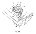
- FIGS. 16 and 17 are isometric and lateral side elevation views showing the adjustment block, tibial trial, poly trial insert, and floating trial inserted while the floating trial is being pinned to the talus.
- FIG. 18 is an isometric view of an embodiment of the adjustment block providing proximal-distal and medial-lateral adjustments.
- FIG. 19 is an anterior top plan view of the adjustment block of FIG. 18 , with a drill guide attached to its tool holder.
- FIG. 1 is an isometric diagram of a position adjustment device 100 (also referred to below as an “adjustment block”) for positioning of drilling and cutting tools for tibia resectioning, and for tibia trial insertion.
- the adjustment block 100 provides a common reference location for locating tools and the tibia trial components throughout the sizing, resectioning and trial procedure.
- the adjustment block 100 is small enough in profile to position a cut guide into the wound space close to the tibia bone without applying excess skin tension. The physician can use the adjustment block to position a drill guide and/or cut guide closer to the tibia bone, to make more accurate cuts with less chance of the blade or pins flexing.
- the adjustment block 100 has three independently positionable frames 110 , 120 , and 130 for precisely positioning a tool holder 134 adjacent the joint to be replaced.
- the first frame 110 is configured to be attached to two fixation pins 150 which have been inserted in the anterior surface of the tibia, near the distal end of the tibia.
- a locking screw 112 actuates a locking plate (not shown), which bears against the fixation pins 150 to secure the adjustment block 100 relative to the pins.
- the first frame has a proximal-distal adjustment knob 111 coaxially connected to a screw 113 .
- the screw 113 can have an Acme thread, trapezoidal thread, square thread or other suitable thread for leadscrew use.
- the second frame 120 is fixedly attached or unitarily formed with a leadscrew nut (not shown), which the screw 113 drives.
- Rotation of the proximal-distal adjustment knob 111 rotates screw 113 to advance or retract the second frame 120 in the proximal-distal direction.
- the physician advances the locking screw 114 to lock the second frame 120 to the first frame 110 in place.
- the second frame 120 has at least one medial-lateral adjustment knob 121 a , 121 b coaxially connected to a screw 123 .
- the screw 123 can have an Acme thread, trapezoidal thread, square thread or other suitable thread for leadscrew use.
- the screw 123 drives a leadscrew nut (not shown), to which the third frame 130 is fixedly attached or unitarily formed with. Rotation of the medial-lateral adjustment knob 121 a or 121 b rotates screw 123 to move the third frame 130 in the medial-lateral direction.
- the physician advances the locking screw 122 to lock the leadscrew 123 of the second frame 120 in place.
- the third frame 130 has an anterior-posterior adjustment knob 131 coaxially connected to a screw 133 .
- the screw 133 can have an Acme thread, trapezoidal thread, square thread or other suitable thread for leadscrew use.
- the screw 133 drives a leadscrew nut 136 , to which a tool holder 134 is fixedly attached or with which tool holder 134 is unitarily formed.
- Rotation of the anterior-posterior adjustment knob 131 rotates screw 133 to move the tool holder 134 in the anterior-posterior direction.
- the tool holder 134 is adapted to hold a drilling tool, a cutting tool, or a tibia trial 210 .
- FIG. 2 is an exploded view showing the adjustment block 100 , tibia trial 210 , poly trial insert 230 and floating trial 250 .
- FIG. 3 is an isometric view of the tibia trial 210 .
- FIG. 4 is an anterior (rear) elevation view of the tibia trial 210 .
- FIG. 5 is a sagittal (side) elevation view of the tibia trial 210 .
- the tibia trial 210 provides the profile of the tibia tray portion of an ankle replacement system.
- the tibia trial 210 comprises a plate 211 with a top surface adapted to fit against a distal surface 262 of the resectioned tibia 260 .
- the plate 211 has a plurality of holes 212 to be used to locate peg holes 263 in the resectioned tibia 260 .
- the plate 211 has a bottom surface 216 adapted to receive a trial insert, such as a poly trial insert 230 .
- An anterior tibia reference member 218 extends from the plate 211 .
- the anterior tibia reference member 218 has a posterior surface 219 adapted to contact an anterior surface 261 of the tibia 260 when the tibia trial 210 is properly positioned.
- the tibia trial 210 has an anterior mounting portion 213 sized and shaped to be mounted to the tool holder 134 of the adjustment block 100 .
- the tibia trial 210 has a notch 217 for aligning an anterior surface of the poly trial insert 230 with the tibia trial 210 . Alignment (or misalignment is readily visible by checking whether the notch 217 is aligned with an edge of the poly trial insert 230 .
- the tibia trial 210 is formed of a strong, corrosion resistant material such as stainless steel or a titanium alloy.
- the poly trial insert 230 is configured to provide the profile of the poly insert of an ankle replacement system.
- the poly trial insert 230 comprises a top surface 231 adapted to be detachably mounted to the bottom surface of the plate 216 of the tibia trial 210 .
- the poly insert 230 has a concave bottom surface 232 with a size and shape of a prosthetic tibia joint surface of the ankle replacement system.
- the thickness of the poly trial insert 230 matches the poly insert of the ankle replacement system to which the poly trial insert 230 corresponds, allowing verification of the size and thickness of the poly insert using the poly trial insert 230 .
- the poly insert of the ankle replacement system has a locking tab to prevent release from the talar tray after surgery; but the poly trial insert 230 has a non-locking tab 233 with a ramped surface, to be detachably inserted in the tibia trial 210 and removed after sizing and resectioning is completed.
- the non-locking tab 233 fits in a corresponding recess (not shown) in the bottom surface 216 of the tibia trial 210 .
- the posterior end of the poly trial insert 230 has an undercut 234 ,
- the poly trial insert 230 is made from the same type of material used in the poly insert of an ankle replacement system.
- the poly trial insert 230 is made of a chemical-resistant material such as polyphenylsulfone, which is also referred to as RadelR.
- FIG. 6 is an isometric view of the floating trial 250 .
- the floating trial 250 is configured to provide a contour that matches the contour of the talar dome of the ankle replacement system.
- the floating trial 250 is configured to be inserted beneath the poly trial insert 230 to contact the concave bottom surface 232 of insert 230 .
- the floating trial 250 comprises a member 251 having at least one convex anterior surface with a size and shape of a prosthetic talar dome of the ankle replacement system, to permit articulation with the concave surface 232 of the insert.
- the posterior surface 255 of the member 251 is shaped to match the contour of the resectioned talus.
- the floating trial 250 has two convex surfaces 251 .
- the floating trial 250 further includes a handle portion 252 which is sized to project from the resection site, so the physician can easily optimize the position of the floating trial for smooth articulation with the poly trial insert 230 .
- the handle 252 of the floating trial 250 has a plurality of pin holes 253 for receiving fixation pins to be used for locating a talar cut guide (not shown). Once the position is optimized, the pins are inserted through the pin holes 253 before completing the resectioning of the talus.
- the floating trial 250 is formed of a strong, corrosion resistant material such as stainless steel or a titanium alloy.
- the floating trial 250 also has one or more anterior chamfers 254 for reference and alignment.
- FIGS. 7-17 show various stages of a method of resectioning and trialing, using the adjustment block 100 , optional drill guide 280 , optional cut guide 290 , tibia trial 210 , poly trial insert 230 and floating trial 250 . This is one example of a use of the devices, but is not limiting.
- FIG. 7 shows the adjustment block 100 fixed to the fixation pins 150 (e.g., 3.2 mm pins) which have been inserted in the anterior surface of the tibia 260 near the distal end 261 of the tibia.
- FIG. 7 also shows a drill guide 280 attached to the tool holder 134 of the adjustment block 100 , with the first frame 110 slightly above the anterior surface of the tibia 260 .
- the tool holder 134 is stage with a pair of pins 135
- the drill guide 280 has a corresponding pair of mounting ears 283 with holes adapted to snap onto the pins 135 .
- This tool holder design is just exemplary in nature, and other embodiments include other suitable mounting structures.
- the drill guide 280 is a small profile device sized and shaped to be inserted beneath the refracted skin (not shown) in the ankle region.
- the drill guide 280 has at least two guide holes 281 to be used to drill pilot holes in the tibia 260 .
- the drill guide also has pin holes 282 that can be used to pin the drill guide to the bone, for position fixation.
- the drill guide 280 has sizing patterns 285 showing the size and location of one or more resectioning cuts corresponding to the holes to be drilled using the drill guide 280 .
- the drill guide 280 has one or more reference lines 286 that the physician can optionally use to position the drill guide 280 (by adjusting the proximal-distal knob 111 , the medial-lateral knob 121 a or 121 b , and the anterior-posterior knob.
- the lines 285 , 286 are visible under a fluoroscope, so the physician can view the position and size of the lines 285 , 286 in situ, relative to the patient's bones.
- the physician sizes the tibial tray component of the ankle replacement system by mounting a drill guide 280 on the tool holder and adjusting its position as described above.
- the position adjustment device (adjustment block) 100 is locked with the tool holder 134 at first coordinates in the proximal-distal and medial-lateral directions.
- the physician views the X-ray of the tibia bone 260 and drill guide 280 and determines whether it is the optimum size and position for the patient.
- the position can be adjusted based on the X-ray, using knobs 111 , 121 , 131 . If the size of the resectioning cut corresponding to the drill guide 280 is too large or too small, the physician removes the drill guide, selects a different size drill guide, and snaps the new drill guide onto the tool holder 134 of the adjustment block 100 .
- the drill guide is then repositioned against the tibia, imaged by fluoroscope, and the size is again checked.
- the drill guide 280 can be made of plastic, while the circles surrounding holes 281 and the patterns 285 , 286 can be made of metal. Thus, only the circles surrounding holes 281 and the patterns 285 , 286 appear on the X-ray, superimposed against the tibia 260 and talus 265 .
- some embodiments use a single drill guide 280 for sizing, location of fixation pins by holes 282 and drilling corners 281
- other embodiments use a first guide (sizing guide) with holes 282 and patterns 285 , 286 for sizing the tibia trial 210 and locating the fixation pins, and a second guide (drilling guide) with holes 281 and 282 for performing the drilling. Because the adjustment block 100 and the pins in holes 282 provide common references, the holes 281 can still be drilled with proper location relative to the pin holes 282 and patterns 285 , 286 .
- FIG. 8 shows the tibia 260 with adjustment block 100 and drill guide 280 .
- Soft tissue is omitted for ease of viewing.
- the physician pins the drill guide 280 to the tibia 260 using (e.g., 2.4 mm) fixation pins 287 inserted through the pin holes 282 and trimmed to extend slightly above the drill guide 280 .
- the physician drills holes in the tibia 260 through the guides holes 281 using the drill guide 280 and drill 288 .
- the holes thus drilled in the bone 260 define corners of a resectioning cut to be performed in the tibia.
- FIG. 9 shows the adjustment block 100 still fixed to the fixation pins 150 in the same position, with a cut guide 290 mounted to the tool holder 134 of the adjustment block 100 .
- the cut guide 290 has a plurality of slots 295 , sized and located to connect the corner holes drilled with the drill guide 280 .
- the cut guide 290 is sized and shaped to match the drill guide 280 .
- the physician has a set of drill guides 280 and a corresponding set of cut guides 290 .
- the selection of a drill guide size automatically selects the corresponding cut guide size to make cuts which are sized and located to connect the corner holes drilled with the drill guide 280 , as described above.
- the cut guide 290 has a corresponding pair of mounting ears 293 with holes adapted to snap onto the pins 135 .
- the cut guide 290 also has pin holes 292 which are sized and located to receive the fixation pins 287 . This aligns the position of the cut guide 290 with the position previously occupied by the drill guide 280 , to ensure alignment of the resectioning cuts with the previously drilled corner holes.
- the cut guide 290 includes additional ears 296 with pin holes for receiving additional fixation pins 297 .
- the physician slides the holes 292 of cut guide 290 over the fixation pins 287 and snaps the cut guide into place on the tool holder 134 .
- the physician can then insert two more fixation pins 297 through the pin holes of ears 296 and into the talus bone 265 .
- the physician performs the resectioning cuts through the guide slots 295 , cutting the bone to connect the previously drilled holes.
- one cut guide 290 is used for both the tibia resection and the first cut of the talar resection.
- the cut guide 290 is then removed from the surgery site, and detached from the adjustment block 100 .
- the sections of the tibia 260 and talus 265 that have been cut are removed, along with the fixation pins 287 and 297 .
- the tibia cut guide is only used to resection the tibia, and a separate cut guide is used to resection the talus after removal of the tibia cut guide.
- the use of the adjustment block 100 permits the holes 281 to be drilled first with a first tool, and the cuts to be performed afterwards with a second tool, while maintaining accurate alignment between the holes and the cuts. Drilling the holes first avoids stress concentrations at the corners of the resectioned distal tibia.
- some embodiments described herein use a drill guide 280 and a cut guide 290 commonly fixed using the adjustment block 100 and fixation pins 287 , other embodiments attach different tools to the tool holder 134 for purpose of resectioning the tibia and talus.
- some embodiments (not shown) include a cut guide without using a separate drill guide.
- the physician inserts the tibia trial 210 , poly trial insert 230 and floating trial 250 , while the adjustment block 100 is still locked to the two fixation pins 150 , and the tool holder 134 is in the first coordinates in the proximal-distal and medial-lateral directions.
- the physician returns the adjustment block to the same coordinates to locate the tool holder 134 at the same position to complete the procedure. Because the fixation pins 150 are excluded from the distal portion of the tibia removed by the resection, the fixation pins 150 are available throughout the procedure for use in adjusting or correcting the resection cuts.
- FIGS. 10 and 11 show the adjustment block in position with the tibia trial 210 attached.
- the adjustment block 100 is adjusted to position the tool holder in an anterior-posterior direction, while the tool holder is at the first coordinates in the proximal-distal and medial-lateral directions.
- the tibia trial 210 is repositioned in the posterior direction until a predetermined portion of the tibia trail contacts an anterior cortex of the tibia.
- the position of the third frame 130 is adjusted until the posterior surface 219 of anterior tibia reference member 218 extending from the plate 211 contacts the anterior cortex of the tibia 260 .
- FIG. 12 shows the tibia 260 and talus 265 with the adjustment block and tibia trial 210 in position.
- the tibia peg drill (not shown) is placed in the head of a tibia peg drill guide 299 , and is inserted in the holes 212 ( FIG. 3 ) of the tibia trial 210 .
- the physician drills a plurality (e.g., 3) peg holes 263 in the distal surface 262 of the resectioned tibia 260 using the tibia peg drill 299 .
- the holes 212 ( FIG. 3 ) of the tibia trial 210 are used to locate these holes 263 .
- FIG. 13 shows the distal end 261 of the tibia 260 at the completion of the peg drilling, with the three peg holes 263 in the resectioned surface 262 of the tibia.
- the tibia trial 210 is used to verify size and shape of the resectioning using the tibia trial, prior to implanting the ankle replacement system.
- the steps of attaching the tibia trial 210 to the tool holder 134 , adjusting the position adjustment device 100 to position the tool holder 134 in an anterior-posterior direction, and placing the tibia trial 210 on the resectioned tibia 260 using the tool holder 134 can be formed without inserting any additional location fixing pins into the tibia, while the tool holder is locked in the first coordinates in the proximal-distal and medial-lateral directions.
- FIGS. 14 and 15 show the adjustment block 100 and tibia trial 210 , after installing the poly trial insert 230 into the tibia trial 210 and positioning the floating trial 250 between the talus 265 and the poly insert trial 230 , to permit articulation with the concave surface 232 of the poly insert trial 230 while the tool holder is in the first coordinates in the proximal-distal and medial-lateral directions.
- the physician can now assess the fit of the ankle replacement system, including size, anterior-posterior position, and whether the tibia has been sized, drilled and cut optimally. If any adjustments are deemed appropriate to the tibia resectioning, the physician can reapply the cut guide with the adjustment block set to the same proximal-distal and medial-lateral coordinates used before.
- the talar implant anterior-posterior coordinate is determined by moving the floating trial 250 to the location where it best articulates with the concave surface 232 of the poly trial insert 230 .
- Two additional fixation pins 298 are inserted through the pin holes 253 of the floating trial 250 using 2 mm K-wire, for example.
- Additional resection guides (not shown) can be positioned by sliding pin holes in the resection guide(s) over the fixation pins 298 .
- the remaining two talar cuts are then performed, to match the geometry of the talar dome implant of the ankle replacement system.
- a position adjustment device (adjustment block) 100 as described above provides a fixed point of reference that facilitates the AP position of the tibial and talar implants of an ankle replacement system.
- the adjustment block 100 is capable of fixing a tibial trial 210 via a modular connection 134 to avoid insertion of additional pins in the distal tibia.
- the tibial trial 210 while attached to the adjustment block 100 , allows the user to set the tibial implant anterior-posterior position by abutting the anterior post 218 against the tibial bone.
- the tibial trial 210 also serves as a drill guide to prepare the tibial pegs on the tibial implant.
- the tibial trial 210 while rigidly fixed to the adjustment block 100 then translates the anterior-posterior position to the talar trial 250 by using the poly trial insert 230 to articulate with the talar (dome) trial 250 .
- the talar trial 250 also has chamfer indicators 254 to help the user determine the optimal talar anterior-posterior position.
- the system and method described above uses the adjustment block 100 as a fixed reference to associate all other instruments used for trial sizing and trials related to tibial side of the ankle replacement.
- a tibial sizer e.g., drill guide 280
- tibial resection guide e.g., cut guide 290
- tibial trial 210 can all be anchored at the same position defined by the adjustment block 100 . This method preserves the distal layer of the tibia to avoid excess pin holes from fixation pins and devices.
- the compact size of the adjustment block allows the tools to be fixed and placed close to the surgery site, for more accurate cuts, with reduced chance of components flexing.
- Sizing guides e.g., drill guide 280
- resection guides e.g. cut guide 290
- the position of the tools and trials can be accurately adjusted by turning the adjustment knobs 111 , 121 , 131 in a small area.
- FIGS. 18 and 19 show another embodiment of the adjustment block 300 .
- the adjustment block 300 has two independently positionable frames 110 , 120 for precisely positioning a tool holder 330 in the proximal-distal and medial-lateral directions, adjacent the joint to be replaced.
- the first frame 110 is configured to be attached to two fixation pins 150 which have been inserted in the anterior surface of the tibia, near the distal end of the tibia.
- a locking screw 112 actuates a locking plate (not shown), which bears against the fixation pins 150 to secure the adjustment block 100 relative to the pins.
- the first frame has a proximal-distal adjustment knob 111 coaxially connected to a screw 113 .
- the screw 113 can have an Acme thread, trapezoidal thread, square thread or other suitable thread for leadscrew use.
- the second frame 120 is fixedly attached or unitarily formed with a leadscrew nut (not shown), which the screw 113 drives.
- Rotation of the proximal-distal adjustment knob 111 rotates screw 113 to advance or retract the second frame 120 in the proximal-distal direction.
- the physician advances the locking screw 114 to lock the second frame 120 to the first frame 110 in place.
- the second frame 120 has at least one medial-lateral adjustment knob 121 a , 121 b coaxially connected to a screw 123 .
- the screw 123 can have an Acme thread, trapezoidal thread, square thread or other suitable thread for leadscrew use.
- the screw 123 drives a leadscrew nut (not shown), to which the tool holder 330 is fixedly attached or unitarily formed with. Rotation of the medial-lateral adjustment knob 121 a or 121 b rotates screw 123 to move the tool holder 330 in the medial-lateral direction.
- the physician advances the locking screw 122 to lock the leadscrew 123 of the second frame 120 in place.
- the position of the tool holder 330 in the anterior-posterior direction is determined by location of the first frame 110 relative to the pins 150 .
- the tool holder 330 can have any of a variety of configurations for easily attaching a tool or trial.
- FIGS. 18 and 19 show a non-limiting example in which the tool or trial is attached to the adjustment block 300 by a dovetail joint 332 .
- FIG. 19 shows an example of a drill guide 380 adapted for mounting to the dovetail joint 332 of tool holder 330 .
- the drill guide 380 has corner holes 381 and fixation holes 382 , 383 and sizing patterns 385 .
- Other tools e.g., a cut guide
- trials e.g., tibia trial
Abstract
Description
Claims (4)
Priority Applications (35)
| Application Number | Priority Date | Filing Date | Title |
|---|---|---|---|
| US14/100,799 US9480571B2 (en) | 2012-12-27 | 2013-12-09 | Ankle replacement system and method |
| CA2836651A CA2836651C (en) | 2012-12-27 | 2013-12-16 | Ankle replacement system and method |
| AU2013270628A AU2013270628B2 (en) | 2012-12-27 | 2013-12-16 | Ankle replacement system and method |
| BR102013032428A BR102013032428A2 (en) | 2012-12-27 | 2013-12-17 | ankle replacement system and method |
| EP13198280.3A EP2749257B1 (en) | 2012-12-27 | 2013-12-19 | Ankle replacement system |
| CN201310712965.9A CN103892942B (en) | 2012-12-27 | 2013-12-20 | Ankle joint exchange system |
| JP2013265425A JP5749788B2 (en) | 2012-12-27 | 2013-12-24 | Artificial ankle joint replacement device |
| US14/365,474 US9974588B2 (en) | 2012-12-27 | 2014-03-14 | Ankle replacement system and method |
| US14/335,379 US10136904B2 (en) | 2012-12-27 | 2014-07-18 | Ankle replacement system and method |
| US14/373,185 US10080573B2 (en) | 2012-12-27 | 2014-07-18 | Ankle replacement system and method |
| US14/445,928 US9918724B2 (en) | 2012-12-27 | 2014-07-29 | Ankle replacement system and method |
| US14/445,997 US10149687B2 (en) | 2012-12-27 | 2014-07-29 | Ankle replacement system and method |
| US14/446,921 US9907561B2 (en) | 2012-12-27 | 2014-07-30 | Ankle replacement system and method |
| US14/448,242 US9993255B2 (en) | 2012-12-27 | 2014-07-31 | Ankle replacement system and method |
| JP2015081634A JP5955434B2 (en) | 2012-12-27 | 2015-04-13 | System and method for artificial ankle joint replacement |
| AU2015202080A AU2015202080B2 (en) | 2012-12-27 | 2015-04-23 | Ankle replacement system and method |
| JP2016117842A JP2016195776A (en) | 2012-12-27 | 2016-06-14 | System and method of artificial ankle joint replacement |
| US15/335,949 US10321922B2 (en) | 2012-12-27 | 2016-10-27 | Ankle replacement system and method |
| US15/881,321 US11311302B2 (en) | 2012-12-27 | 2018-01-26 | Ankle replacement system and method |
| US15/902,616 US11109872B2 (en) | 2012-12-27 | 2018-02-22 | Ankle replacement system and method |
| US15/965,044 US11116527B2 (en) | 2012-12-27 | 2018-04-27 | Ankle replacement system and method |
| JP2018092289A JP6556291B2 (en) | 2012-12-27 | 2018-05-11 | System and method for artificial ankle joint replacement |
| US15/982,337 US11116524B2 (en) | 2012-12-27 | 2018-05-17 | Ankle replacement system and method |
| US16/047,425 US10888336B2 (en) | 2012-12-27 | 2018-07-27 | Ankle replacement system and method |
| US16/168,083 US11103257B2 (en) | 2012-12-27 | 2018-10-23 | Ankle replacement system and method |
| US16/190,371 US11147569B2 (en) | 2012-12-27 | 2018-11-14 | Ankle replacement system and method |
| US16/405,212 US11116521B2 (en) | 2012-12-27 | 2019-05-07 | Ankle replacement system and method |
| US17/137,585 US11786260B2 (en) | 2012-12-27 | 2020-12-30 | Ankle replacement system and method |
| US17/392,517 US11766270B2 (en) | 2012-12-27 | 2021-08-03 | Ankle replacement system and method |
| US17/394,482 US11759215B2 (en) | 2012-12-27 | 2021-08-05 | Ankle replacement system and method |
| US17/398,182 US20210361302A1 (en) | 2012-12-27 | 2021-08-10 | Ankle replacement system and method |
| US17/400,620 US20210369288A1 (en) | 2012-12-27 | 2021-08-12 | Ankle replacement system and method |
| US17/402,760 US11864778B2 (en) | 2012-12-27 | 2021-08-16 | Ankle replacement system and method |
| US17/648,030 US11701133B2 (en) | 2012-12-27 | 2022-01-14 | Ankle replacement system and method |
| US18/495,844 US20240050108A1 (en) | 2012-12-27 | 2023-10-27 | Ankle replacement system and method |
Applications Claiming Priority (2)
| Application Number | Priority Date | Filing Date | Title |
|---|---|---|---|
| US201261746393P | 2012-12-27 | 2012-12-27 | |
| US14/100,799 US9480571B2 (en) | 2012-12-27 | 2013-12-09 | Ankle replacement system and method |
Related Child Applications (5)
| Application Number | Title | Priority Date | Filing Date |
|---|---|---|---|
| US14/365,474 Continuation-In-Part US9974588B2 (en) | 2012-12-27 | 2014-03-14 | Ankle replacement system and method |
| PCT/US2014/027448 Continuation-In-Part WO2014152535A1 (en) | 2012-12-27 | 2014-03-14 | Ankle replacement system and method |
| US14/373,185 Continuation-In-Part US10080573B2 (en) | 2012-12-27 | 2014-07-18 | Ankle replacement system and method |
| US14/445,997 Continuation-In-Part US10149687B2 (en) | 2012-12-27 | 2014-07-29 | Ankle replacement system and method |
| US15/335,949 Division US10321922B2 (en) | 2012-12-27 | 2016-10-27 | Ankle replacement system and method |
Publications (2)
| Publication Number | Publication Date |
|---|---|
| US20140188236A1 US20140188236A1 (en) | 2014-07-03 |
| US9480571B2 true US9480571B2 (en) | 2016-11-01 |
Family
ID=51018089
Family Applications (4)
| Application Number | Title | Priority Date | Filing Date |
|---|---|---|---|
| US14/100,799 Active 2034-11-05 US9480571B2 (en) | 2012-12-27 | 2013-12-09 | Ankle replacement system and method |
| US15/335,949 Active 2034-12-24 US10321922B2 (en) | 2012-12-27 | 2016-10-27 | Ankle replacement system and method |
| US16/405,212 Active 2034-07-11 US11116521B2 (en) | 2012-12-27 | 2019-05-07 | Ankle replacement system and method |
| US17/400,620 Pending US20210369288A1 (en) | 2012-12-27 | 2021-08-12 | Ankle replacement system and method |
Family Applications After (3)
| Application Number | Title | Priority Date | Filing Date |
|---|---|---|---|
| US15/335,949 Active 2034-12-24 US10321922B2 (en) | 2012-12-27 | 2016-10-27 | Ankle replacement system and method |
| US16/405,212 Active 2034-07-11 US11116521B2 (en) | 2012-12-27 | 2019-05-07 | Ankle replacement system and method |
| US17/400,620 Pending US20210369288A1 (en) | 2012-12-27 | 2021-08-12 | Ankle replacement system and method |
Country Status (3)
| Country | Link |
|---|---|
| US (4) | US9480571B2 (en) |
| EP (1) | EP2749257B1 (en) |
| CN (1) | CN103892942B (en) |
Cited By (11)
| Publication number | Priority date | Publication date | Assignee | Title |
|---|---|---|---|---|
| US20200060697A1 (en) * | 2017-07-28 | 2020-02-27 | Wright Medical Technology, Inc. | Joint osteotomy system and method |
| WO2020124052A1 (en) * | 2018-12-13 | 2020-06-18 | Paragon 28, Inc. | Instruments, guides and related methods for total ankle replacement |
| US20210298911A1 (en) * | 2018-12-13 | 2021-09-30 | Paragon 28, Inc. | Total ankle replacement surgical method |
| US20210369287A1 (en) * | 2020-06-01 | 2021-12-02 | Pmo Llc | Bone Deformity Treatment System, Device, And Related Methods |
| US20220167999A1 (en) | 2018-12-13 | 2022-06-02 | Paragon 28, Inc. | Alignment instruments and methods for use in total ankle replacement |
| US20220233333A1 (en) * | 2015-03-06 | 2022-07-28 | Howmedica Osteonics Corp. | Surgical method and instrumentation assembly for positioning an ankle prosthesis |
| US11464522B2 (en) | 2018-12-13 | 2022-10-11 | Paragon 28, Inc. | Distractors having attachable paddles, impaction devices, and methods for use in total ankle replacement |
| US11590001B2 (en) | 2017-07-05 | 2023-02-28 | Wright Medical Technology, Inc. | Anterior ankle approach system and method |
| US11602354B2 (en) * | 2016-06-21 | 2023-03-14 | 3D Metal Printing Limited | Surgical assembly, stabilisation plate and methods |
| EP4265201A1 (en) | 2022-02-28 | 2023-10-25 | Wright Medical Technology, Inc. | Surgical guides |
| US11857207B2 (en) | 2016-03-23 | 2024-01-02 | Wright Medical Technology, Inc. | Circular fixator system and method |
Families Citing this family (10)
| Publication number | Priority date | Publication date | Assignee | Title |
|---|---|---|---|---|
| GB2528101A (en) * | 2014-07-10 | 2016-01-13 | Ortho Solutions Ltd | Apparatus for surgically replacing a human ankle joint |
| EP3307182B1 (en) | 2015-06-09 | 2020-11-11 | Zimmer, Inc. | Patient-specific instrumentation for total ankle replacement |
| EP3590450B1 (en) | 2017-03-03 | 2023-11-01 | Teijin Nakashima Medical Co., Ltd. | Osteotomy assistance kit |
| ES2832739T3 (en) | 2017-09-22 | 2021-06-11 | Stryker European Operations Holdings Llc | Talar ankle implant |
| CN107874809B (en) * | 2017-11-14 | 2020-08-04 | 北京爱康宜诚医疗器材有限公司 | Ankle osteotomy guiding device and method for determining ankle osteotomy position |
| US11000296B2 (en) | 2017-12-20 | 2021-05-11 | Encore Medical, L.P. | Joint instrumentation and associated methods of use |
| CA3122564A1 (en) * | 2018-12-13 | 2020-06-18 | Paragon 28, Inc. | Resection guides, sweeping reamers, and methods for use in total ankle replacement |
| AU2020283377B2 (en) * | 2019-05-29 | 2022-08-04 | Wright Medical Technology, Inc. | Preparing a tibia for receiving tibial implant component of a replacement ankle |
| US11918237B2 (en) * | 2020-03-02 | 2024-03-05 | Orthosoft Ulc | Systems and methods for robotic ankle arthroplasty |
| CN113693792A (en) * | 2021-08-30 | 2021-11-26 | 北京市春立正达医疗器械股份有限公司 | Locking type prosthesis for ankle joint |
Citations (29)
| Publication number | Priority date | Publication date | Assignee | Title |
|---|---|---|---|---|
| US3872519A (en) | 1974-04-04 | 1975-03-25 | Nicholas J Giannestras | Total ankle prosthesis |
| US3889300A (en) | 1974-08-28 | 1975-06-17 | Wright Mfg | Articulated two-part prosthesis replacing the ankle joint |
| US5312412A (en) | 1993-02-03 | 1994-05-17 | Whipple Terry L | Fixation alignment guide for surgical use |
| US5354300A (en) | 1993-01-15 | 1994-10-11 | Depuy Inc. | Drill guide apparatus for installing a transverse pin |
| US5776200A (en) | 1995-02-15 | 1998-07-07 | Smith & Nephew, Inc. | Tibial trial prosthesis and bone preparation system |
| US6342056B1 (en) | 2000-02-04 | 2002-01-29 | Jean-Marc Mac-Thiong | Surgical drill guide and method for using the same |
| US20020082607A1 (en) | 2000-12-27 | 2002-06-27 | Heldreth Mark A. | Prosthesis evaluation assembly and associated method |
| US6620168B1 (en) | 1998-10-13 | 2003-09-16 | Stryker Technologies Corporation | Methods and tools for tibial intermedullary revision surgery and associated tibial components |
| US6645215B1 (en) | 2002-08-07 | 2003-11-11 | Howmedica Osteonics Corp. | Tibial rotation guide |
| US20040030399A1 (en) | 2000-05-22 | 2004-02-12 | Joseph-Guy Asencio | Articulation prosthesis |
| US7001394B2 (en) | 2000-12-28 | 2006-02-21 | Depuy Products, Inc. | Method and apparatus for surgically preparing a tibia for implantation of a prosthetic implant component which has an offset stem |
| WO2006023824A2 (en) | 2004-08-19 | 2006-03-02 | Kinetikos Medical Incorporated | Ankle prosthesis and method of curved resection |
| WO2006099270A2 (en) | 2005-03-14 | 2006-09-21 | Topez Orthopedics, Inc. | Ankle replacement system |
| US20060247788A1 (en) | 2005-03-31 | 2006-11-02 | The Regents Of The University Of California | Total ankle arthroplasty |
| WO2007084846A2 (en) | 2006-01-20 | 2007-07-26 | Hasselman Carl T | Method of preparing an ankle joint for replacement, joint prosthesis, and cutting alignment apparatus for use in performing an arthroplasty procedure |
| US20070276400A1 (en) | 2003-09-22 | 2007-11-29 | Gary Moore | Drill Guide Assembly |
| US20090105767A1 (en) | 2007-10-18 | 2009-04-23 | Inbone Technologies, Inc. | Total joint subsidence protector |
| WO2009158522A1 (en) | 2008-06-25 | 2009-12-30 | Small Bone Innovations, Inc. | Surgical instrumentation and methods of use for implanting a prothesis |
| US20100305572A1 (en) | 2003-10-14 | 2010-12-02 | Saltzman Charles L | Ankle prosthesis methods |
| US7850698B2 (en) | 2005-02-17 | 2010-12-14 | Zimmer Technology, Inc. | Tibial trialing assembly and method of trialing a tibial implant |
| US8034114B2 (en) | 1999-10-22 | 2011-10-11 | Inbone Technologies, Inc. | Systems and methods for installing ankle replacement prostheses |
| US8048164B2 (en) | 1999-10-22 | 2011-11-01 | Inbone Technologies, Inc. | Ankle replacement system |
| WO2011151657A1 (en) | 2010-06-03 | 2011-12-08 | Biomet Uk Healthcare Limited | Guiding tool |
| US8114091B2 (en) | 2006-01-24 | 2012-02-14 | Tornier | Surgical instrumentation kit for inserting an ankle prosthesis |
| US20120277745A1 (en) * | 2009-04-21 | 2012-11-01 | Emmanuel Lizee | Systems and methods for positioning a foot in ankle arthrodesis |
| US8313492B2 (en) | 2008-05-30 | 2012-11-20 | Wright Medical Technology, Inc. | Drill guide assembly |
| US20130116797A1 (en) * | 2011-11-04 | 2013-05-09 | Tornier Sas | Surgical instrumentation assembly for positioning an ankle prosthesis |
| US8475463B2 (en) | 2009-04-13 | 2013-07-02 | George J. Lian | Systems and instrumentalities for use in total ankle replacement surgery |
| US8808303B2 (en) * | 2009-02-24 | 2014-08-19 | Microport Orthopedics Holdings Inc. | Orthopedic surgical guide |
Family Cites Families (161)
| Publication number | Priority date | Publication date | Assignee | Title |
|---|---|---|---|---|
| JPS5026651B2 (en) | 1972-04-13 | 1975-09-02 | ||
| DE2236141B2 (en) | 1972-07-22 | 1976-07-08 | Fa. Waldemar Link, 2000 Hamburg | PARTIAL DENTURE FOR A HUMAN ANKLE |
| GB1446593A (en) | 1973-01-12 | 1976-08-18 | Nat Res Dev | Endoprosthetic ankle joint devices |
| GB1447368A (en) | 1973-02-09 | 1976-08-25 | Nat Res Dev | Endo prosthetic ankle joint devices |
| US3886599A (en) | 1974-07-25 | 1975-06-03 | Schlein Louis Charles | Surgically implantable total ankle prosthesis |
| US3975778A (en) | 1975-07-14 | 1976-08-24 | Newton Iii St Elmo | Total ankle arthroplasty |
| US3987500A (en) | 1976-01-28 | 1976-10-26 | Schlein Allen P | Surgically implantable total ankle prosthesis |
| US4021864A (en) | 1976-04-14 | 1977-05-10 | The Regents Of The University Of California | Ankle prosthesis |
| US4069518A (en) | 1976-08-31 | 1978-01-24 | Groth Jr Harry E | Total ankle prosthesis |
| CH607579A5 (en) | 1976-11-15 | 1978-09-15 | Sulzer Ag | |
| GB1579773A (en) | 1977-07-18 | 1980-11-26 | Nat Res Dev | Endoprosthetic bone joint devices |
| US4166292A (en) | 1977-09-08 | 1979-09-04 | Carbomedics, Inc. | Stress reinforced artificial joint prostheses |
| US4204284A (en) | 1977-11-16 | 1980-05-27 | Lord Corporation | Joint prosthesis with contoured pin |
| US4470158A (en) | 1978-03-10 | 1984-09-11 | Biomedical Engineering Corp. | Joint endoprosthesis |
| US4309778A (en) | 1979-07-02 | 1982-01-12 | Biomedical Engineering Corp. | New Jersey meniscal bearing knee replacement |
| US4755185A (en) | 1987-01-27 | 1988-07-05 | Boehringer Mannheim Corporation | Prosthetic joint |
| US4968316A (en) | 1988-12-12 | 1990-11-06 | Hergenroeder Patrick T | Arthroscopic ankle joint distraction method |
| SE466937B (en) | 1989-04-25 | 1992-05-04 | Branemark Per Ingvar | ANCHORING DEVICE FOR BONE WOVEN APPLICABLE PROTESTES, SPEC LED MECHANISMS |
| US5326365A (en) | 1992-04-10 | 1994-07-05 | Alvine Franklin G | Ankle implant |
| US5423825A (en) | 1992-06-10 | 1995-06-13 | Levine; Andrew S. | Spinal fusion instruments and methods |
| US5476466A (en) | 1993-07-20 | 1995-12-19 | Zimmer, Inc. | Orthopaedic positioning instrument |
| US5674223A (en) | 1994-02-16 | 1997-10-07 | Joint Medical Products Corporation | Instrument for implanting a femoral knee prosthesis |
| US6402787B1 (en) | 2000-01-30 | 2002-06-11 | Bill J. Pope | Prosthetic hip joint having at least one sintered polycrystalline diamond compact articulation surface and substrate surface topographical features in said polycrystalline diamond compact |
| US5885299A (en) | 1994-09-15 | 1999-03-23 | Surgical Dynamics, Inc. | Apparatus and method for implant insertion |
| US6033405A (en) | 1994-09-15 | 2000-03-07 | Surgical Dynamics, Inc. | Apparatus and method for implant insertion |
| US5578039A (en) | 1995-02-15 | 1996-11-26 | Smith & Nephew Richards Inc. | Tibial resection instrumentation and surgical method |
| US5702468A (en) | 1995-03-09 | 1997-12-30 | Uresil Corporation | Carpal bone biaxially restrained prosthesis |
| US5766259A (en) | 1995-03-14 | 1998-06-16 | Sammarco; Giacomo J. | Total ankle prosthesis and method |
| JP3501542B2 (en) | 1995-04-07 | 2004-03-02 | 富久 腰野 | Medical hard tissue replacements and artificial joints |
| US5735904A (en) | 1995-07-05 | 1998-04-07 | Pappas; Michael J. | Spacer for establishng prosthetic gap and ligamentous tension |
| US5634927A (en) | 1995-07-06 | 1997-06-03 | Zimmer, Inc. | Sizing plate and drill guide assembly for orthopaedic knee instrumentation |
| US5817097A (en) | 1995-08-03 | 1998-10-06 | Synvasive Technology, Inc. | Bone saw blade guide with magnet |
| US5601563A (en) | 1995-08-25 | 1997-02-11 | Zimmer, Inc. | Orthopaedic milling template with attachable cutting guide |
| US5716361A (en) | 1995-11-02 | 1998-02-10 | Masini; Michael A. | Bone cutting guides for use in the implantation of prosthetic joint components |
| FR2747302B1 (en) | 1996-04-11 | 1998-09-11 | Tornier Sa | ANKLE PROSTHESIS |
| FR2755600B1 (en) | 1996-11-08 | 1999-02-05 | Proseal | INSTRUMENTATION FOR PLACEMENT OF A BLADE-CLIP FOR SUBTRACTION OSTEOTOMY FOR THE TREATMENT OF GONARTHROSIS |
| US5880976A (en) | 1997-02-21 | 1999-03-09 | Carnegie Mellon University | Apparatus and method for facilitating the implantation of artificial components in joints |
| FR2760353B1 (en) | 1997-03-10 | 1999-07-02 | Tornier Sa | ANKLE PROSTHESIS |
| US5935132A (en) | 1997-12-10 | 1999-08-10 | Johnson & Johnson Professional, Inc. | Surgical guide and cutting system |
| US6090145A (en) | 1997-12-10 | 2000-07-18 | Societe Industrielle De Combustible Nucleaire S I C N | Partial scaphoid implant and method of treating ailments of the scaphoid |
| WO2000004839A1 (en) | 1998-06-09 | 2000-02-03 | Nuvasive, Inc. | Spinal surgery guidance platform |
| KR100459673B1 (en) | 1998-09-11 | 2004-12-04 | 아르고메디컬 악티엔게젤샤프트 | Implantable prosthesis having at least two sections which can be displaced in relation to one another, and the use of displaceable sections |
| US6109672A (en) | 1998-10-09 | 2000-08-29 | Valeo Electrical Systems, Inc. | Combination window release and wiper system and method |
| IT1310371B1 (en) | 1999-05-13 | 2002-02-13 | Ist Ortopedici Rizzoli | HUMAN ARTICULATION PROSTHESIS DEVICE, IN PARTICULAR TIBOTARSIC PARTICULATION AND RELATED METHOD OF IMPLANTATION. |
| FR2797178B1 (en) | 1999-08-05 | 2002-02-22 | Tornier Sa | MALLEOLAR IMPLANT FOR PARTIAL OR TOTAL ANKLE PROSTHESIS AND ANCILLARY MATERIAL FOR PLACING SUCH AN IMPLANT |
| US6875235B2 (en) | 1999-10-08 | 2005-04-05 | Bret A. Ferree | Prosthetic joints with contained compressible resilient members |
| FR2800601B1 (en) | 1999-11-05 | 2002-01-04 | Europ Foot Platform | ANKLE PROSTHESIS |
| US6245109B1 (en) | 1999-11-18 | 2001-06-12 | Intellijoint Systems, Ltd. | Artificial joint system and method utilizing same for monitoring wear and displacement of artificial joint members |
| JP5026651B2 (en) | 2000-03-10 | 2012-09-12 | スミス アンド ネフュー インコーポレーテッド | Device used for knee arthroplasty |
| US6423061B1 (en) | 2000-03-14 | 2002-07-23 | Amei Technologies Inc. | High tibial osteotomy method and apparatus |
| AU2001257137A1 (en) | 2000-04-21 | 2001-11-07 | Behrooz Tohidi | Wear-resistant artificial joint |
| US7163541B2 (en) | 2002-12-03 | 2007-01-16 | Arthrosurface Incorporated | Tibial resurfacing system |
| US6679917B2 (en) | 2000-05-01 | 2004-01-20 | Arthrosurface, Incorporated | System and method for joint resurface repair |
| US8177841B2 (en) | 2000-05-01 | 2012-05-15 | Arthrosurface Inc. | System and method for joint resurface repair |
| US7678151B2 (en) | 2000-05-01 | 2010-03-16 | Ek Steven W | System and method for joint resurface repair |
| US7713305B2 (en) | 2000-05-01 | 2010-05-11 | Arthrosurface, Inc. | Articular surface implant |
| US6610067B2 (en) | 2000-05-01 | 2003-08-26 | Arthrosurface, Incorporated | System and method for joint resurface repair |
| EP2314257B9 (en) | 2000-05-01 | 2013-02-27 | ArthroSurface, Inc. | System for joint resurface repair |
| US6478800B1 (en) | 2000-05-08 | 2002-11-12 | Depuy Acromed, Inc. | Medical installation tool |
| US6478799B1 (en) | 2000-06-29 | 2002-11-12 | Richard V. Williamson | Instruments and methods for use in performing knee surgery |
| US20020173853A1 (en) | 2001-05-17 | 2002-11-21 | Corl Harry E. | Movable joint and method for coating movable joints |
| AUPR597701A0 (en) | 2001-06-28 | 2001-07-19 | Portland Orthopaedics Pty Limited | Joint prosthesis |
| US7618421B2 (en) | 2001-10-10 | 2009-11-17 | Howmedica Osteonics Corp. | Tools for femoral resection in knee surgery |
| DE50209198D1 (en) | 2002-03-08 | 2007-02-15 | Link Waldemar Gmbh Co | ANKLE ENDOPROSTHESIS |
| US6875222B2 (en) | 2002-03-12 | 2005-04-05 | Depuy Products, Inc. | Blade for resection of bone for prosthesis implantation, blade stop and method |
| US7615082B2 (en) | 2002-03-22 | 2009-11-10 | Hjs Gelenk System Gmbh | Artificial joint |
| US6863691B2 (en) | 2002-04-29 | 2005-03-08 | Timothy J. Short | Ankle implant |
| US8801720B2 (en) | 2002-05-15 | 2014-08-12 | Otismed Corporation | Total joint arthroplasty system |
| US20030236522A1 (en) | 2002-06-21 | 2003-12-25 | Jack Long | Prosthesis cavity cutting guide, cutting tool and method |
| US7025790B2 (en) | 2002-06-27 | 2006-04-11 | Concepts In Medicine Iii, L.L.C. | Ankle joint prosthesis and its method of implantation |
| US20040039394A1 (en) | 2002-08-26 | 2004-02-26 | Conti Stephen F. | Ankle fusion guide and method |
| US20040068322A1 (en) | 2002-10-04 | 2004-04-08 | Ferree Bret A. | Reduced-friction artificial joints and components therefor |
| US7252684B2 (en) | 2002-11-06 | 2007-08-07 | Southwest Research Institute | Ceramic in replacement components |
| US6939380B2 (en) | 2002-12-23 | 2005-09-06 | Depuy Products, Inc. | Mobile talar component for total ankle replacement implant |
| US7011687B2 (en) | 2003-01-06 | 2006-03-14 | Depuy Products, Inc. | Ankle prosthesis with a front loading bearing and associated method |
| US20040167631A1 (en) | 2003-02-21 | 2004-08-26 | Kenny Luchesi | Fixation surface for ankle prosthesis |
| US20040186585A1 (en) | 2003-03-21 | 2004-09-23 | Lawrence Feiwell | Sphere-on-sphere ankle prosthesis |
| US7238190B2 (en) | 2003-03-28 | 2007-07-03 | Concepts In Medicine Iii, Llc | Surgical apparatus to allow replacement of degenerative ankle tissue |
| US7481814B1 (en) | 2003-07-28 | 2009-01-27 | Biomet Manufacturing Corporation | Method and apparatus for use of a mill or reamer |
| US7153325B2 (en) | 2003-08-01 | 2006-12-26 | Ultra-Kinetics, Inc. | Prosthetic intervertebral disc and methods for using the same |
| KR20100086066A (en) | 2003-08-27 | 2010-07-29 | 링크 아메리카, 인코포레이티드 | Ankle-joint endoprosthesis |
| US7534270B2 (en) | 2003-09-03 | 2009-05-19 | Integra Lifesciences Corporation | Modular total ankle prosthesis apparatuses and methods |
| US9445916B2 (en) | 2003-10-22 | 2016-09-20 | Pioneer Surgical Technology, Inc. | Joint arthroplasty devices having articulating members |
| US7261740B2 (en) * | 2003-10-29 | 2007-08-28 | Wright Medical Technology, Inc. | Tibial knee prosthesis |
| AU2004293042A1 (en) | 2003-11-20 | 2005-06-09 | Arthrosurface, Inc. | Retrograde delivery of resurfacing devices |
| US7625379B2 (en) | 2004-01-26 | 2009-12-01 | Warsaw Orthopedic, Inc. | Methods and instrumentation for inserting intervertebral grafts and devices |
| US7485147B2 (en) | 2004-02-13 | 2009-02-03 | Pappas Michael J | Ankle prosthesis including tibial component having peripheral wall for preventing the formation of bone cysts |
| US7323012B1 (en) | 2004-03-17 | 2008-01-29 | Biomet Manufacturing Corp. | Ankle implant |
| US7803158B2 (en) | 2004-03-26 | 2010-09-28 | Depuy Products, Inc. | Navigated pin placement for orthopaedic procedures |
| US7763080B2 (en) | 2004-04-30 | 2010-07-27 | Depuy Products, Inc. | Implant system with migration measurement capacity |
| US20050251147A1 (en) | 2004-05-07 | 2005-11-10 | Novak Vincent P | Open wedge osteotomy system and surgical method |
| US20050288792A1 (en) | 2004-06-23 | 2005-12-29 | Landes Mark D | Modular ankle prosthesis and associated method |
| EP1765201A4 (en) | 2004-06-28 | 2013-01-23 | Arthrosurface Inc | System for articular surface replacement |
| US9237958B2 (en) | 2004-06-30 | 2016-01-19 | Synergy Disc Replacement Inc. | Joint prostheses |
| US20060009857A1 (en) | 2004-07-08 | 2006-01-12 | Gibbs Phillip M | Method and apparatus for surface hardening implants |
| US8167888B2 (en) | 2004-08-06 | 2012-05-01 | Zimmer Technology, Inc. | Tibial spacer blocks and femoral cutting guide |
| AT502926B1 (en) | 2004-11-08 | 2011-04-15 | Alphamed Medizintechnik Fischer Gmbh | ANKLE PROSTHESIS ELEMENTS |
| US7648508B2 (en) | 2004-11-30 | 2010-01-19 | Stryker Trauma S.A. | Bone plating implants, instruments and methods |
| US20070038303A1 (en) | 2006-08-15 | 2007-02-15 | Ebi, L.P. | Foot/ankle implant and associated method |
| US7935119B2 (en) | 2005-01-31 | 2011-05-03 | Ibalance Medical, Inc. | Method for performing an open wedge, high tibial osteotomy |
| US8317797B2 (en) | 2005-02-08 | 2012-11-27 | Rasmussen G Lynn | Arthroplasty systems and methods for optimally aligning and tensioning a knee prosthesis |
| US20060235541A1 (en) | 2005-04-15 | 2006-10-19 | Zimmer Technology, Inc. | Bearing implant |
| US7727239B2 (en) | 2005-06-10 | 2010-06-01 | Zimmer Technology, Inc. | Milling system with guide paths and related methods for resecting a joint articulation surface |
| US20070100346A1 (en) | 2005-10-27 | 2007-05-03 | Wyss Joseph G | Support for locating instrument guides |
| BRPI0619626A2 (en) | 2005-12-12 | 2011-10-04 | Link Waldemar Gmbh Co | intermediate element stent graft |
| US9808262B2 (en) | 2006-02-15 | 2017-11-07 | Howmedica Osteonics Corporation | Arthroplasty devices and related methods |
| WO2007098423A2 (en) | 2006-02-17 | 2007-08-30 | Paradigm Spine, L.L.C. | Method and system for performing interspinous space preparation for receiving an implant |
| JP2009531078A (en) | 2006-03-02 | 2009-09-03 | タラス メディカル, インコーポレイテッド | Artificial bone |
| GB0606837D0 (en) | 2006-04-05 | 2006-05-17 | Depuy Int Ltd | Cutting guide instrument |
| US20080015602A1 (en) | 2006-06-22 | 2008-01-17 | Howmedica Osteonics Corp. | Cutting block for bone resection |
| FR2906999B1 (en) | 2006-10-13 | 2009-06-05 | Tornier Sas | PROTHETIC SET OF ANKLE |
| US9278006B2 (en) | 2006-10-26 | 2016-03-08 | European Foot Platform Sc | Ankle prosthesis with neutral position adjustment |
| US8323346B2 (en) | 2006-11-17 | 2012-12-04 | Scyon Orthopaedics Ag | Wear-reducing geometry of articulations in total joint replacements |
| US20090234360A1 (en) | 2006-12-12 | 2009-09-17 | Vladimir Alexander | Laser assisted total joint arthroplasty |
| CA2672555A1 (en) | 2006-12-15 | 2008-06-26 | Synthes Usa, Llc | Osteotomy guide and method of cutting the medial distal tibia employing the same |
| US7909882B2 (en) | 2007-01-19 | 2011-03-22 | Albert Stinnette | Socket and prosthesis for joint replacement |
| GB2448740B (en) | 2007-04-26 | 2012-03-14 | Derek James Wallace Mcminn | Alignment device |
| AU2008250951B2 (en) | 2007-05-14 | 2014-06-05 | Queen's University At Kingston | Patient-specific surgical guidance tool and method of use |
| WO2008151644A1 (en) | 2007-06-12 | 2008-12-18 | Link America, Inc. | Endoprosthesis having a convex design |
| WO2009015009A1 (en) | 2007-07-20 | 2009-01-29 | Talus Medical, Inc. | Methods and devices for deploying biological implants |
| US8715359B2 (en) | 2009-10-30 | 2014-05-06 | Depuy (Ireland) | Prosthesis for cemented fixation and method for making the prosthesis |
| US8632600B2 (en) | 2007-09-25 | 2014-01-21 | Depuy (Ireland) | Prosthesis with modular extensions |
| US20110035018A1 (en) | 2007-09-25 | 2011-02-10 | Depuy Products, Inc. | Prosthesis with composite component |
| US10398561B2 (en) | 2007-09-26 | 2019-09-03 | DePuy Synthes Products, Inc. | Talar implant system and method |
| US20090105840A1 (en) | 2007-10-18 | 2009-04-23 | Inbone Technologies, Inc. | Fibular stiffener and bony defect replacer |
| EP2262448A4 (en) | 2008-03-03 | 2014-03-26 | Arthrosurface Inc | Bone resurfacing system and method |
| US9168065B2 (en) | 2008-04-30 | 2015-10-27 | Moximed, Inc. | Ball and socket assembly |
| GB0809721D0 (en) | 2008-05-28 | 2008-07-02 | Univ Bath | Improvements in or relating to joints and/or implants |
| US8012217B2 (en) | 2008-07-03 | 2011-09-06 | Fellowship of Orthopaedic Researchers, LLC | Talar implants and methods of use |
| US20100057216A1 (en) | 2008-07-23 | 2010-03-04 | Jamy Gannoe | System and method for joint resurfacing with dynamic fixation |
| US9808345B2 (en) | 2008-07-24 | 2017-11-07 | Iorthopedics, Inc. | Resilient arthroplasty device |
| JP2010075697A (en) | 2008-09-22 | 2010-04-08 | Buechel-Pappas Trust | Fixed bearing joint endoprosthesis with combined congruent-incongruent prosthetic articulation surface |
| US9017334B2 (en) * | 2009-02-24 | 2015-04-28 | Microport Orthopedics Holdings Inc. | Patient specific surgical guide locator and mount |
| DE102009011648A1 (en) | 2009-03-04 | 2010-09-09 | Advanced Medical Technologies Ag | Implant system with support elements |
| WO2010120346A1 (en) | 2009-04-13 | 2010-10-21 | George John Lian | Custom radiographically designed cutting guides and instruments for use in total ankle replacement surgery |
| US8268007B2 (en) | 2009-06-26 | 2012-09-18 | The Cleveland Clinic Foundation | Multi-piece prosthetic joint component |
| US9510949B2 (en) | 2009-06-26 | 2016-12-06 | The Cleveland Clinic Foundation | Prosthetic joint component with rotation-regulating structure |
| DE102009031269B4 (en) | 2009-06-30 | 2013-07-25 | Universität Rostock | Device for in-situ milling of articular surfaces |
| US20110035019A1 (en) | 2009-07-09 | 2011-02-10 | Wright State University | Total ankle replacement system |
| WO2011008739A2 (en) | 2009-07-14 | 2011-01-20 | Medicinelodge, Inc. Dba Imds Co-Innovation | Joint arthrodesis and arthroplasty |
| GB0913674D0 (en) | 2009-08-06 | 2009-09-16 | Depuy Ireland | Surgical instrument and system of surgical instrument |
| US9839434B2 (en) | 2009-10-29 | 2017-12-12 | Zimmer, Inc. | Patient-specific mill guide |
| EP2501340B1 (en) | 2009-11-16 | 2017-01-18 | New York Society for the Ruptured and Crippled Maintaining the Hospital for Special Surgery | Prosthetic condylar joints with articulating bearing surfaces having a translating contact point during rotation thereof |
| KR20120104580A (en) | 2009-11-20 | 2012-09-21 | 니 크리에이션스, 엘엘씨 | Navigation and positioning instruments for joint repair |
| EP2512354A4 (en) | 2009-12-18 | 2015-09-09 | Biomimedica Inc | Method, device, and system for shaving and shaping of a joint |
| US9492281B2 (en) | 2010-02-19 | 2016-11-15 | European Foot Platform Sc | Ankle prosthesis with simplified adjustment |
| US8303667B2 (en) | 2010-03-02 | 2012-11-06 | Alastair Younger | Fastening system for prostheses |
| US8591596B2 (en) | 2010-05-28 | 2013-11-26 | DePuy Synthes Products, LLC | Semi-constrained ankle prosthesis having a rotating bearing insert |
| US8647391B2 (en) | 2010-07-07 | 2014-02-11 | Global Orthopaedic Solutions Llc | Malleolar replacement devices |
| US20120010718A1 (en) | 2010-07-08 | 2012-01-12 | Still Gregory P | Partial ankle joint replacement implant |
| US8690956B2 (en) | 2010-08-23 | 2014-04-08 | Fellowship Of Orthopaedic Researchers, Inc. | Talar implants and methods of use |
| US10531897B2 (en) | 2010-08-26 | 2020-01-14 | Moximed, Inc. | Implantable device for relieving ankle pain |
| US8940046B2 (en) | 2010-10-01 | 2015-01-27 | Maxx Orthopedics, Inc. | Method of implanting a prosthesis device using bone cement in liquid form |
| US8668743B2 (en) | 2010-11-02 | 2014-03-11 | Adam D. Perler | Prosthetic device with multi-axis dual bearing assembly and methods for resection |
| EP2677946B1 (en) | 2011-02-22 | 2016-08-17 | Zimmer Knee Creations, Inc. | Guide systems for joint repair |
| US9186154B2 (en) | 2011-03-17 | 2015-11-17 | Zimmer, Inc. | Patient-specific instruments for total ankle arthroplasty |
| US20120245701A1 (en) | 2011-03-24 | 2012-09-27 | Rudolf Zak | Hemi Ankle Implant |
| WO2012145707A1 (en) | 2011-04-22 | 2012-10-26 | Imds Corporation | Ankle arthroplasty |
| CA2836651C (en) | 2012-12-27 | 2016-03-22 | Wright Medical Technology, Inc. | Ankle replacement system and method |
| US10080573B2 (en) | 2012-12-27 | 2018-09-25 | Wright Medical Technology, Inc. | Ankle replacement system and method |
| CN105228541A (en) | 2013-03-14 | 2016-01-06 | 瑞特医疗技术公司 | Ankle replacement system and method |
-
2013
- 2013-12-09 US US14/100,799 patent/US9480571B2/en active Active
- 2013-12-19 EP EP13198280.3A patent/EP2749257B1/en not_active Not-in-force
- 2013-12-20 CN CN201310712965.9A patent/CN103892942B/en not_active Expired - Fee Related
-
2016
- 2016-10-27 US US15/335,949 patent/US10321922B2/en active Active
-
2019
- 2019-05-07 US US16/405,212 patent/US11116521B2/en active Active
-
2021
- 2021-08-12 US US17/400,620 patent/US20210369288A1/en active Pending
Patent Citations (32)
| Publication number | Priority date | Publication date | Assignee | Title |
|---|---|---|---|---|
| US3872519A (en) | 1974-04-04 | 1975-03-25 | Nicholas J Giannestras | Total ankle prosthesis |
| US3889300A (en) | 1974-08-28 | 1975-06-17 | Wright Mfg | Articulated two-part prosthesis replacing the ankle joint |
| US5354300A (en) | 1993-01-15 | 1994-10-11 | Depuy Inc. | Drill guide apparatus for installing a transverse pin |
| US5312412A (en) | 1993-02-03 | 1994-05-17 | Whipple Terry L | Fixation alignment guide for surgical use |
| US5776200A (en) | 1995-02-15 | 1998-07-07 | Smith & Nephew, Inc. | Tibial trial prosthesis and bone preparation system |
| US6620168B1 (en) | 1998-10-13 | 2003-09-16 | Stryker Technologies Corporation | Methods and tools for tibial intermedullary revision surgery and associated tibial components |
| US8034114B2 (en) | 1999-10-22 | 2011-10-11 | Inbone Technologies, Inc. | Systems and methods for installing ankle replacement prostheses |
| US8048164B2 (en) | 1999-10-22 | 2011-11-01 | Inbone Technologies, Inc. | Ankle replacement system |
| US6342056B1 (en) | 2000-02-04 | 2002-01-29 | Jean-Marc Mac-Thiong | Surgical drill guide and method for using the same |
| US20040030399A1 (en) | 2000-05-22 | 2004-02-12 | Joseph-Guy Asencio | Articulation prosthesis |
| US6942670B2 (en) | 2000-12-27 | 2005-09-13 | Depuy Orthopaedics, Inc. | Prosthesis evaluation assembly and associated method |
| US20020082607A1 (en) | 2000-12-27 | 2002-06-27 | Heldreth Mark A. | Prosthesis evaluation assembly and associated method |
| US7001394B2 (en) | 2000-12-28 | 2006-02-21 | Depuy Products, Inc. | Method and apparatus for surgically preparing a tibia for implantation of a prosthetic implant component which has an offset stem |
| US6645215B1 (en) | 2002-08-07 | 2003-11-11 | Howmedica Osteonics Corp. | Tibial rotation guide |
| US20070276400A1 (en) | 2003-09-22 | 2007-11-29 | Gary Moore | Drill Guide Assembly |
| US20100305572A1 (en) | 2003-10-14 | 2010-12-02 | Saltzman Charles L | Ankle prosthesis methods |
| WO2006023824A2 (en) | 2004-08-19 | 2006-03-02 | Kinetikos Medical Incorporated | Ankle prosthesis and method of curved resection |
| US7850698B2 (en) | 2005-02-17 | 2010-12-14 | Zimmer Technology, Inc. | Tibial trialing assembly and method of trialing a tibial implant |
| WO2006099270A2 (en) | 2005-03-14 | 2006-09-21 | Topez Orthopedics, Inc. | Ankle replacement system |
| US7534246B2 (en) | 2005-03-14 | 2009-05-19 | Inbone Technologies, Inc. | Ankle replacement system |
| US20060247788A1 (en) | 2005-03-31 | 2006-11-02 | The Regents Of The University Of California | Total ankle arthroplasty |
| US8002841B2 (en) * | 2006-01-20 | 2011-08-23 | Synthes Usa, Llc | Method of preparing an ankle joint for replacement, joint prosthesis, and cutting alignment apparatus for use in performing an arthroplasty procedure |
| WO2007084846A2 (en) | 2006-01-20 | 2007-07-26 | Hasselman Carl T | Method of preparing an ankle joint for replacement, joint prosthesis, and cutting alignment apparatus for use in performing an arthroplasty procedure |
| US8114091B2 (en) | 2006-01-24 | 2012-02-14 | Tornier | Surgical instrumentation kit for inserting an ankle prosthesis |
| US20090105767A1 (en) | 2007-10-18 | 2009-04-23 | Inbone Technologies, Inc. | Total joint subsidence protector |
| US8313492B2 (en) | 2008-05-30 | 2012-11-20 | Wright Medical Technology, Inc. | Drill guide assembly |
| WO2009158522A1 (en) | 2008-06-25 | 2009-12-30 | Small Bone Innovations, Inc. | Surgical instrumentation and methods of use for implanting a prothesis |
| US8808303B2 (en) * | 2009-02-24 | 2014-08-19 | Microport Orthopedics Holdings Inc. | Orthopedic surgical guide |
| US8475463B2 (en) | 2009-04-13 | 2013-07-02 | George J. Lian | Systems and instrumentalities for use in total ankle replacement surgery |
| US20120277745A1 (en) * | 2009-04-21 | 2012-11-01 | Emmanuel Lizee | Systems and methods for positioning a foot in ankle arthrodesis |
| WO2011151657A1 (en) | 2010-06-03 | 2011-12-08 | Biomet Uk Healthcare Limited | Guiding tool |
| US20130116797A1 (en) * | 2011-11-04 | 2013-05-09 | Tornier Sas | Surgical instrumentation assembly for positioning an ankle prosthesis |
Non-Patent Citations (3)
| Title |
|---|
| International Preliminary Report on Patentability issued by the International Bureau of WIPO in connection with International patent application No. PCT/US2014/027448, Sep. 15, 2015, 8 pages. |
| International Search Report for PCT/US2014/027448 dated Jul. 2, 2014. |
| Search report for EP 13198280 dated Feb. 5, 2014. |
Cited By (16)
| Publication number | Priority date | Publication date | Assignee | Title |
|---|---|---|---|---|
| US20220233333A1 (en) * | 2015-03-06 | 2022-07-28 | Howmedica Osteonics Corp. | Surgical method and instrumentation assembly for positioning an ankle prosthesis |
| US11857207B2 (en) | 2016-03-23 | 2024-01-02 | Wright Medical Technology, Inc. | Circular fixator system and method |
| US11602354B2 (en) * | 2016-06-21 | 2023-03-14 | 3D Metal Printing Limited | Surgical assembly, stabilisation plate and methods |
| US11590001B2 (en) | 2017-07-05 | 2023-02-28 | Wright Medical Technology, Inc. | Anterior ankle approach system and method |
| US20200060697A1 (en) * | 2017-07-28 | 2020-02-27 | Wright Medical Technology, Inc. | Joint osteotomy system and method |
| US11653960B2 (en) * | 2017-07-28 | 2023-05-23 | Wright Medical Technology, Inc. | Joint osteotomy system and method |
| US11571311B2 (en) | 2018-12-13 | 2023-02-07 | Paragon 28, Inc. | Total ankle replacement trial and preparation systems |
| US11464522B2 (en) | 2018-12-13 | 2022-10-11 | Paragon 28, Inc. | Distractors having attachable paddles, impaction devices, and methods for use in total ankle replacement |
| US11399949B2 (en) | 2018-12-13 | 2022-08-02 | Paragon 28, Inc. | Total ankle replacement trial and preparation systems, guides, instruments and related methods |
| US20220167999A1 (en) | 2018-12-13 | 2022-06-02 | Paragon 28, Inc. | Alignment instruments and methods for use in total ankle replacement |
| US20210298911A1 (en) * | 2018-12-13 | 2021-09-30 | Paragon 28, Inc. | Total ankle replacement surgical method |
| WO2020124052A1 (en) * | 2018-12-13 | 2020-06-18 | Paragon 28, Inc. | Instruments, guides and related methods for total ankle replacement |
| US11871943B2 (en) | 2018-12-13 | 2024-01-16 | Paragon 28, Inc. | Alignment instruments and methods for use in total ankle replacement |
| US20210369287A1 (en) * | 2020-06-01 | 2021-12-02 | Pmo Llc | Bone Deformity Treatment System, Device, And Related Methods |
| US11839383B2 (en) * | 2020-06-01 | 2023-12-12 | Trilliant Surgical, Llc | Bone deformity treatment system, device, and related methods |
| EP4265201A1 (en) | 2022-02-28 | 2023-10-25 | Wright Medical Technology, Inc. | Surgical guides |
Also Published As
| Publication number | Publication date |
|---|---|
| US20170042555A1 (en) | 2017-02-16 |
| US20190254688A1 (en) | 2019-08-22 |
| CN103892942B (en) | 2016-08-17 |
| US11116521B2 (en) | 2021-09-14 |
| EP2749257B1 (en) | 2015-07-29 |
| US20210369288A1 (en) | 2021-12-02 |
| US10321922B2 (en) | 2019-06-18 |
| CN103892942A (en) | 2014-07-02 |
| EP2749257A1 (en) | 2014-07-02 |
| US20140188236A1 (en) | 2014-07-03 |
Similar Documents
| Publication | Publication Date | Title |
|---|---|---|
| US11116521B2 (en) | Ankle replacement system and method | |
| CA2836651C (en) | Ankle replacement system and method | |
| US11759215B2 (en) | Ankle replacement system and method | |
| US11864778B2 (en) | Ankle replacement system and method | |
| US20210361302A1 (en) | Ankle replacement system and method | |
| US20180344328A1 (en) | Ankle replacement system and method | |
| AU2015202080B2 (en) | Ankle replacement system and method |
Legal Events
| Date | Code | Title | Description |
|---|---|---|---|
| AS | Assignment |
Owner name: WRIGHT MEDICAL TECHNOLOGY, INC., TENNESSEE Free format text: ASSIGNMENT OF ASSIGNORS INTEREST;ASSIGNORS:MCGINLEY, SHAWN E.;HOWLES, ROBERT M.;DHILLON, BRAHAM K.;AND OTHERS;SIGNING DATES FROM 20140117 TO 20140127;REEL/FRAME:032052/0668 |
|
| STCF | Information on status: patent grant |
Free format text: PATENTED CASE |
|
| AS | Assignment |
Owner name: MIDCAP FINANCIAL TRUST, AS AGENT, MARYLAND Free format text: SECURITY INTEREST;ASSIGNOR:WRIGHT MEDICAL TECHNOLOGY, INC.;REEL/FRAME:041257/0126 Effective date: 20161223 |
|
| MAFP | Maintenance fee payment |
Free format text: PAYMENT OF MAINTENANCE FEE, 4TH YEAR, LARGE ENTITY (ORIGINAL EVENT CODE: M1551); ENTITY STATUS OF PATENT OWNER: LARGE ENTITY Year of fee payment: 4 |
|
| AS | Assignment |
Owner name: BIOMIMETIC THERAPEUTICS CANADA, INC., TENNESSEE Free format text: RELEASE BY SECURED PARTY;ASSIGNOR:MIDCAP FUNDING IV TRUST;REEL/FRAME:054480/0001 Effective date: 20201112 Owner name: TORNIER US HOLDINGS, INC., MINNESOTA Free format text: RELEASE BY SECURED PARTY;ASSIGNOR:MIDCAP FUNDING IV TRUST;REEL/FRAME:054480/0001 Effective date: 20201112 Owner name: WRIGHT MEDICAL GROUP N.V., NETHERLANDS Free format text: RELEASE BY SECURED PARTY;ASSIGNOR:MIDCAP FUNDING IV TRUST;REEL/FRAME:054480/0001 Effective date: 20201112 Owner name: TORNIER, INC., MINNESOTA Free format text: RELEASE BY SECURED PARTY;ASSIGNOR:MIDCAP FUNDING IV TRUST;REEL/FRAME:054480/0001 Effective date: 20201112 Owner name: WRIGHT MEDICAL GROUP, INC., TENNESSEE Free format text: RELEASE BY SECURED PARTY;ASSIGNOR:MIDCAP FUNDING IV TRUST;REEL/FRAME:054480/0001 Effective date: 20201112 Owner name: WRIGHT MEDICAL GROUP INTELLECTUAL PROPERTY, INC., TENNESSEE Free format text: RELEASE BY SECURED PARTY;ASSIGNOR:MIDCAP FUNDING IV TRUST;REEL/FRAME:054480/0001 Effective date: 20201112 Owner name: ORTHOPRO, L.L.C., TENNESSEE Free format text: RELEASE BY SECURED PARTY;ASSIGNOR:MIDCAP FUNDING IV TRUST;REEL/FRAME:054480/0001 Effective date: 20201112 Owner name: SOLANA SURGICAL, LLC, TENNESSEE Free format text: RELEASE BY SECURED PARTY;ASSIGNOR:MIDCAP FUNDING IV TRUST;REEL/FRAME:054480/0001 Effective date: 20201112 Owner name: BIOMIMETIC THERAPEUTICS USA, INC., TENNESSEE Free format text: RELEASE BY SECURED PARTY;ASSIGNOR:MIDCAP FUNDING IV TRUST;REEL/FRAME:054480/0001 Effective date: 20201112 Owner name: WHITE BOX ORTHOPEDICS, LLC, TENNESSEE Free format text: RELEASE BY SECURED PARTY;ASSIGNOR:MIDCAP FUNDING IV TRUST;REEL/FRAME:054480/0001 Effective date: 20201112 Owner name: BIOMIMETIC THERAPEUTICS, LLC, TENNESSEE Free format text: RELEASE BY SECURED PARTY;ASSIGNOR:MIDCAP FUNDING IV TRUST;REEL/FRAME:054480/0001 Effective date: 20201112 Owner name: TROOPER HOLDINGS INC., MINNESOTA Free format text: RELEASE BY SECURED PARTY;ASSIGNOR:MIDCAP FUNDING IV TRUST;REEL/FRAME:054480/0001 Effective date: 20201112 Owner name: WRIGHT MEDICAL CAPITAL, INC., TENNESSEE Free format text: RELEASE BY SECURED PARTY;ASSIGNOR:MIDCAP FUNDING IV TRUST;REEL/FRAME:054480/0001 Effective date: 20201112 Owner name: INBONE TECHNOLOGIES, INC., TENNESSEE Free format text: RELEASE BY SECURED PARTY;ASSIGNOR:MIDCAP FUNDING IV TRUST;REEL/FRAME:054480/0001 Effective date: 20201112 Owner name: ORTHOHELIX SURGICAL DESIGNS, INC., MINNESOTA Free format text: RELEASE BY SECURED PARTY;ASSIGNOR:MIDCAP FUNDING IV TRUST;REEL/FRAME:054480/0001 Effective date: 20201112 Owner name: WRIGHT MEDICAL TECHNOLOGY, INC., TENNESSEE Free format text: RELEASE BY SECURED PARTY;ASSIGNOR:MIDCAP FUNDING IV TRUST;REEL/FRAME:054480/0001 Effective date: 20201112 |