US9488089B2 - Method of controlling operation of an engine having both an exhaust fluid recirculation apparatus and an exhaust fluid treatment apparatus - Google Patents
Method of controlling operation of an engine having both an exhaust fluid recirculation apparatus and an exhaust fluid treatment apparatus Download PDFInfo
- Publication number
- US9488089B2 US9488089B2 US14/416,239 US201314416239A US9488089B2 US 9488089 B2 US9488089 B2 US 9488089B2 US 201314416239 A US201314416239 A US 201314416239A US 9488089 B2 US9488089 B2 US 9488089B2
- Authority
- US
- United States
- Prior art keywords
- valve
- exhaust fluid
- combustion
- combustion unit
- treatment apparatus
- Prior art date
- Legal status (The legal status is an assumption and is not a legal conclusion. Google has not performed a legal analysis and makes no representation as to the accuracy of the status listed.)
- Active
Links
- 239000012530 fluid Substances 0.000 title claims abstract description 185
- 238000000034 method Methods 0.000 title claims abstract description 52
- 238000002485 combustion reaction Methods 0.000 claims abstract description 100
- 239000000446 fuel Substances 0.000 claims abstract description 54
- 238000011144 upstream manufacturing Methods 0.000 claims abstract description 21
- 238000004891 communication Methods 0.000 claims description 6
- 238000002347 injection Methods 0.000 claims description 6
- 239000007924 injection Substances 0.000 claims description 6
- 230000001419 dependent effect Effects 0.000 claims 5
- 239000003054 catalyst Substances 0.000 description 10
- QGZKDVFQNNGYKY-UHFFFAOYSA-N Ammonia Chemical compound N QGZKDVFQNNGYKY-UHFFFAOYSA-N 0.000 description 8
- 239000004071 soot Substances 0.000 description 7
- 230000001276 controlling effect Effects 0.000 description 5
- 230000003647 oxidation Effects 0.000 description 5
- 238000007254 oxidation reaction Methods 0.000 description 5
- 239000002245 particle Substances 0.000 description 5
- 229910021529 ammonia Inorganic materials 0.000 description 4
- 230000008878 coupling Effects 0.000 description 4
- 238000010168 coupling process Methods 0.000 description 4
- 238000005859 coupling reaction Methods 0.000 description 4
- 239000007789 gas Substances 0.000 description 4
- OKTJSMMVPCPJKN-UHFFFAOYSA-N Carbon Chemical compound [C] OKTJSMMVPCPJKN-UHFFFAOYSA-N 0.000 description 3
- CURLTUGMZLYLDI-UHFFFAOYSA-N Carbon dioxide Chemical compound O=C=O CURLTUGMZLYLDI-UHFFFAOYSA-N 0.000 description 3
- 229910052799 carbon Inorganic materials 0.000 description 3
- XLYOFNOQVPJJNP-UHFFFAOYSA-N water Substances O XLYOFNOQVPJJNP-UHFFFAOYSA-N 0.000 description 3
- IJGRMHOSHXDMSA-UHFFFAOYSA-N Atomic nitrogen Chemical compound N#N IJGRMHOSHXDMSA-UHFFFAOYSA-N 0.000 description 2
- UGFAIRIUMAVXCW-UHFFFAOYSA-N Carbon monoxide Chemical compound [O+]#[C-] UGFAIRIUMAVXCW-UHFFFAOYSA-N 0.000 description 2
- KDLHZDBZIXYQEI-UHFFFAOYSA-N Palladium Chemical compound [Pd] KDLHZDBZIXYQEI-UHFFFAOYSA-N 0.000 description 2
- 229910002092 carbon dioxide Inorganic materials 0.000 description 2
- 239000001569 carbon dioxide Substances 0.000 description 2
- 229910002091 carbon monoxide Inorganic materials 0.000 description 2
- 238000006243 chemical reaction Methods 0.000 description 2
- 239000000470 constituent Substances 0.000 description 2
- 239000000463 material Substances 0.000 description 2
- BASFCYQUMIYNBI-UHFFFAOYSA-N platinum Chemical compound [Pt] BASFCYQUMIYNBI-UHFFFAOYSA-N 0.000 description 2
- 230000008929 regeneration Effects 0.000 description 2
- 238000011069 regeneration method Methods 0.000 description 2
- NINIDFKCEFEMDL-UHFFFAOYSA-N Sulfur Chemical compound [S] NINIDFKCEFEMDL-UHFFFAOYSA-N 0.000 description 1
- 239000005864 Sulphur Substances 0.000 description 1
- XSQUKJJJFZCRTK-UHFFFAOYSA-N Urea Chemical compound NC(N)=O XSQUKJJJFZCRTK-UHFFFAOYSA-N 0.000 description 1
- 239000004202 carbamide Substances 0.000 description 1
- 238000010531 catalytic reduction reaction Methods 0.000 description 1
- 239000011248 coating agent Substances 0.000 description 1
- 238000000576 coating method Methods 0.000 description 1
- 239000002283 diesel fuel Substances 0.000 description 1
- 229930195733 hydrocarbon Natural products 0.000 description 1
- 150000002430 hydrocarbons Chemical class 0.000 description 1
- 238000005259 measurement Methods 0.000 description 1
- 229910052763 palladium Inorganic materials 0.000 description 1
- 229910052697 platinum Inorganic materials 0.000 description 1
- 238000006722 reduction reaction Methods 0.000 description 1
- 230000001105 regulatory effect Effects 0.000 description 1
- 239000007787 solid Substances 0.000 description 1
- 239000007790 solid phase Substances 0.000 description 1
Images


Classifications
-
- F—MECHANICAL ENGINEERING; LIGHTING; HEATING; WEAPONS; BLASTING
- F01—MACHINES OR ENGINES IN GENERAL; ENGINE PLANTS IN GENERAL; STEAM ENGINES
- F01N—GAS-FLOW SILENCERS OR EXHAUST APPARATUS FOR MACHINES OR ENGINES IN GENERAL; GAS-FLOW SILENCERS OR EXHAUST APPARATUS FOR INTERNAL COMBUSTION ENGINES
- F01N3/00—Exhaust or silencing apparatus having means for purifying, rendering innocuous, or otherwise treating exhaust
- F01N3/08—Exhaust or silencing apparatus having means for purifying, rendering innocuous, or otherwise treating exhaust for rendering innocuous
- F01N3/10—Exhaust or silencing apparatus having means for purifying, rendering innocuous, or otherwise treating exhaust for rendering innocuous by thermal or catalytic conversion of noxious components of exhaust
- F01N3/24—Exhaust or silencing apparatus having means for purifying, rendering innocuous, or otherwise treating exhaust for rendering innocuous by thermal or catalytic conversion of noxious components of exhaust characterised by constructional aspects of converting apparatus
- F01N3/36—Arrangements for supply of additional fuel
-
- F—MECHANICAL ENGINEERING; LIGHTING; HEATING; WEAPONS; BLASTING
- F01—MACHINES OR ENGINES IN GENERAL; ENGINE PLANTS IN GENERAL; STEAM ENGINES
- F01N—GAS-FLOW SILENCERS OR EXHAUST APPARATUS FOR MACHINES OR ENGINES IN GENERAL; GAS-FLOW SILENCERS OR EXHAUST APPARATUS FOR INTERNAL COMBUSTION ENGINES
- F01N11/00—Monitoring or diagnostic devices for exhaust-gas treatment apparatus, e.g. for catalytic activity
-
- F—MECHANICAL ENGINEERING; LIGHTING; HEATING; WEAPONS; BLASTING
- F01—MACHINES OR ENGINES IN GENERAL; ENGINE PLANTS IN GENERAL; STEAM ENGINES
- F01N—GAS-FLOW SILENCERS OR EXHAUST APPARATUS FOR MACHINES OR ENGINES IN GENERAL; GAS-FLOW SILENCERS OR EXHAUST APPARATUS FOR INTERNAL COMBUSTION ENGINES
- F01N3/00—Exhaust or silencing apparatus having means for purifying, rendering innocuous, or otherwise treating exhaust
- F01N3/02—Exhaust or silencing apparatus having means for purifying, rendering innocuous, or otherwise treating exhaust for cooling, or for removing solid constituents of, exhaust
- F01N3/021—Exhaust or silencing apparatus having means for purifying, rendering innocuous, or otherwise treating exhaust for cooling, or for removing solid constituents of, exhaust by means of filters
- F01N3/023—Exhaust or silencing apparatus having means for purifying, rendering innocuous, or otherwise treating exhaust for cooling, or for removing solid constituents of, exhaust by means of filters using means for regenerating the filters, e.g. by burning trapped particles
- F01N3/025—Exhaust or silencing apparatus having means for purifying, rendering innocuous, or otherwise treating exhaust for cooling, or for removing solid constituents of, exhaust by means of filters using means for regenerating the filters, e.g. by burning trapped particles using fuel burner or by adding fuel to exhaust
- F01N3/0253—Exhaust or silencing apparatus having means for purifying, rendering innocuous, or otherwise treating exhaust for cooling, or for removing solid constituents of, exhaust by means of filters using means for regenerating the filters, e.g. by burning trapped particles using fuel burner or by adding fuel to exhaust adding fuel to exhaust gases
-
- F—MECHANICAL ENGINEERING; LIGHTING; HEATING; WEAPONS; BLASTING
- F01—MACHINES OR ENGINES IN GENERAL; ENGINE PLANTS IN GENERAL; STEAM ENGINES
- F01N—GAS-FLOW SILENCERS OR EXHAUST APPARATUS FOR MACHINES OR ENGINES IN GENERAL; GAS-FLOW SILENCERS OR EXHAUST APPARATUS FOR INTERNAL COMBUSTION ENGINES
- F01N9/00—Electrical control of exhaust gas treating apparatus
-
- F—MECHANICAL ENGINEERING; LIGHTING; HEATING; WEAPONS; BLASTING
- F02—COMBUSTION ENGINES; HOT-GAS OR COMBUSTION-PRODUCT ENGINE PLANTS
- F02D—CONTROLLING COMBUSTION ENGINES
- F02D41/00—Electrical control of supply of combustible mixture or its constituents
- F02D41/0025—Controlling engines characterised by use of non-liquid fuels, pluralities of fuels, or non-fuel substances added to the combustible mixtures
- F02D41/0047—Controlling exhaust gas recirculation [EGR]
- F02D41/005—Controlling exhaust gas recirculation [EGR] according to engine operating conditions
- F02D41/0055—Special engine operating conditions, e.g. for regeneration of exhaust gas treatment apparatus
-
- F—MECHANICAL ENGINEERING; LIGHTING; HEATING; WEAPONS; BLASTING
- F02—COMBUSTION ENGINES; HOT-GAS OR COMBUSTION-PRODUCT ENGINE PLANTS
- F02D—CONTROLLING COMBUSTION ENGINES
- F02D41/00—Electrical control of supply of combustible mixture or its constituents
- F02D41/0025—Controlling engines characterised by use of non-liquid fuels, pluralities of fuels, or non-fuel substances added to the combustible mixtures
- F02D41/0047—Controlling exhaust gas recirculation [EGR]
- F02D41/0077—Control of the EGR valve or actuator, e.g. duty cycle, closed loop control of position
-
- F—MECHANICAL ENGINEERING; LIGHTING; HEATING; WEAPONS; BLASTING
- F02—COMBUSTION ENGINES; HOT-GAS OR COMBUSTION-PRODUCT ENGINE PLANTS
- F02D—CONTROLLING COMBUSTION ENGINES
- F02D41/00—Electrical control of supply of combustible mixture or its constituents
- F02D41/02—Circuit arrangements for generating control signals
- F02D41/021—Introducing corrections for particular conditions exterior to the engine
- F02D41/0235—Introducing corrections for particular conditions exterior to the engine in relation with the state of the exhaust gas treating apparatus
- F02D41/024—Introducing corrections for particular conditions exterior to the engine in relation with the state of the exhaust gas treating apparatus to increase temperature of the exhaust gas treating apparatus
- F02D41/025—Introducing corrections for particular conditions exterior to the engine in relation with the state of the exhaust gas treating apparatus to increase temperature of the exhaust gas treating apparatus by changing the composition of the exhaust gas, e.g. for exothermic reaction on exhaust gas treating apparatus
-
- F—MECHANICAL ENGINEERING; LIGHTING; HEATING; WEAPONS; BLASTING
- F02—COMBUSTION ENGINES; HOT-GAS OR COMBUSTION-PRODUCT ENGINE PLANTS
- F02D—CONTROLLING COMBUSTION ENGINES
- F02D41/00—Electrical control of supply of combustible mixture or its constituents
- F02D41/02—Circuit arrangements for generating control signals
- F02D41/021—Introducing corrections for particular conditions exterior to the engine
- F02D41/0235—Introducing corrections for particular conditions exterior to the engine in relation with the state of the exhaust gas treating apparatus
- F02D41/027—Introducing corrections for particular conditions exterior to the engine in relation with the state of the exhaust gas treating apparatus to purge or regenerate the exhaust gas treating apparatus
- F02D41/029—Introducing corrections for particular conditions exterior to the engine in relation with the state of the exhaust gas treating apparatus to purge or regenerate the exhaust gas treating apparatus the exhaust gas treating apparatus being a particulate filter
-
- F—MECHANICAL ENGINEERING; LIGHTING; HEATING; WEAPONS; BLASTING
- F02—COMBUSTION ENGINES; HOT-GAS OR COMBUSTION-PRODUCT ENGINE PLANTS
- F02D—CONTROLLING COMBUSTION ENGINES
- F02D41/00—Electrical control of supply of combustible mixture or its constituents
- F02D41/30—Controlling fuel injection
- F02D41/38—Controlling fuel injection of the high pressure type
- F02D41/40—Controlling fuel injection of the high pressure type with means for controlling injection timing or duration
- F02D41/402—Multiple injections
- F02D41/405—Multiple injections with post injections
-
- F—MECHANICAL ENGINEERING; LIGHTING; HEATING; WEAPONS; BLASTING
- F02—COMBUSTION ENGINES; HOT-GAS OR COMBUSTION-PRODUCT ENGINE PLANTS
- F02M—SUPPLYING COMBUSTION ENGINES IN GENERAL WITH COMBUSTIBLE MIXTURES OR CONSTITUENTS THEREOF
- F02M26/00—Engine-pertinent apparatus for adding exhaust gases to combustion-air, main fuel or fuel-air mixture, e.g. by exhaust gas recirculation [EGR] systems
- F02M26/13—Arrangement or layout of EGR passages, e.g. in relation to specific engine parts or for incorporation of accessories
- F02M26/14—Arrangement or layout of EGR passages, e.g. in relation to specific engine parts or for incorporation of accessories in relation to the exhaust system
- F02M26/16—Arrangement or layout of EGR passages, e.g. in relation to specific engine parts or for incorporation of accessories in relation to the exhaust system with EGR valves located at or near the connection to the exhaust system
-
- F—MECHANICAL ENGINEERING; LIGHTING; HEATING; WEAPONS; BLASTING
- F02—COMBUSTION ENGINES; HOT-GAS OR COMBUSTION-PRODUCT ENGINE PLANTS
- F02M—SUPPLYING COMBUSTION ENGINES IN GENERAL WITH COMBUSTIBLE MIXTURES OR CONSTITUENTS THEREOF
- F02M26/00—Engine-pertinent apparatus for adding exhaust gases to combustion-air, main fuel or fuel-air mixture, e.g. by exhaust gas recirculation [EGR] systems
- F02M26/52—Systems for actuating EGR valves
-
- F—MECHANICAL ENGINEERING; LIGHTING; HEATING; WEAPONS; BLASTING
- F01—MACHINES OR ENGINES IN GENERAL; ENGINE PLANTS IN GENERAL; STEAM ENGINES
- F01N—GAS-FLOW SILENCERS OR EXHAUST APPARATUS FOR MACHINES OR ENGINES IN GENERAL; GAS-FLOW SILENCERS OR EXHAUST APPARATUS FOR INTERNAL COMBUSTION ENGINES
- F01N2610/00—Adding substances to exhaust gases
- F01N2610/03—Adding substances to exhaust gases the substance being hydrocarbons, e.g. engine fuel
-
- F—MECHANICAL ENGINEERING; LIGHTING; HEATING; WEAPONS; BLASTING
- F01—MACHINES OR ENGINES IN GENERAL; ENGINE PLANTS IN GENERAL; STEAM ENGINES
- F01N—GAS-FLOW SILENCERS OR EXHAUST APPARATUS FOR MACHINES OR ENGINES IN GENERAL; GAS-FLOW SILENCERS OR EXHAUST APPARATUS FOR INTERNAL COMBUSTION ENGINES
- F01N2610/00—Adding substances to exhaust gases
- F01N2610/14—Arrangements for the supply of substances, e.g. conduits
- F01N2610/1453—Sprayers or atomisers; Arrangement thereof in the exhaust apparatus
- F01N2610/146—Control thereof, e.g. control of injectors or injection valves
-
- Y—GENERAL TAGGING OF NEW TECHNOLOGICAL DEVELOPMENTS; GENERAL TAGGING OF CROSS-SECTIONAL TECHNOLOGIES SPANNING OVER SEVERAL SECTIONS OF THE IPC; TECHNICAL SUBJECTS COVERED BY FORMER USPC CROSS-REFERENCE ART COLLECTIONS [XRACs] AND DIGESTS
- Y02—TECHNOLOGIES OR APPLICATIONS FOR MITIGATION OR ADAPTATION AGAINST CLIMATE CHANGE
- Y02T—CLIMATE CHANGE MITIGATION TECHNOLOGIES RELATED TO TRANSPORTATION
- Y02T10/00—Road transport of goods or passengers
- Y02T10/10—Internal combustion engine [ICE] based vehicles
- Y02T10/12—Improving ICE efficiencies
-
- Y02T10/26—
-
- Y—GENERAL TAGGING OF NEW TECHNOLOGICAL DEVELOPMENTS; GENERAL TAGGING OF CROSS-SECTIONAL TECHNOLOGIES SPANNING OVER SEVERAL SECTIONS OF THE IPC; TECHNICAL SUBJECTS COVERED BY FORMER USPC CROSS-REFERENCE ART COLLECTIONS [XRACs] AND DIGESTS
- Y02—TECHNOLOGIES OR APPLICATIONS FOR MITIGATION OR ADAPTATION AGAINST CLIMATE CHANGE
- Y02T—CLIMATE CHANGE MITIGATION TECHNOLOGIES RELATED TO TRANSPORTATION
- Y02T10/00—Road transport of goods or passengers
- Y02T10/10—Internal combustion engine [ICE] based vehicles
- Y02T10/40—Engine management systems
-
- Y02T10/44—
-
- Y02T10/47—
Definitions
- the disclosure relates to the field of engines having both an exhaust fluid recirculation apparatus and an exhaust fluid treatment apparatus.
- a combustion engine such as a diesel engine, may involve injection of fuel, such as diesel fuel, into one or more cylinders of the engine for combustion.
- fuel may be injected into one or more of the cylinders as a post combustion event with the intention that the fuel passes out of the one or more cylinders without oxidising.
- Such a technique may be useful when the combustion engine is used with an exhaust fluid treatment apparatus. This may allow for unburnt fuel to be delivered to the exhaust fluid treatment apparatus.
- Unburnt fuel may oxidise in the exhaust fluid treatment apparatus which may be useful when there is a desire to increase the temperature in the exhaust fluid treatment apparatus or when there is a desire to burn off, for example, unburnt carbon in the form of soot which may collect in a diesel particulate filter of the exhaust fluid treatment apparatus.
- a method of controlling operation of an engine comprising:
- FIG. 1 shows schematic drawing of an engine comprising a combustion unit, an exhaust fluid recirculation apparatus and an exhaust fluid treatment apparatus to which the method of the present disclosure may be applied;
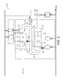
- FIG. 2 shows a schematic drawing of the exhaust fluid treatment apparatus of FIG. 1 ;
- FIG. 3 shows a more detailed schematic drawing of the exhaust fluid treatment apparatus of FIG. 2 ;
- FIG. 4 shows a schematic drawing of an external appearance of the embodiment of FIG. 3 ;
- FIG. 5 shows a flow chart which illustrates an embodiment of the method of the disclosure.
- the engine 1000 may comprise a combustion unit 1010 , an exhaust fluid recirculation apparatus 1020 and an exhaust fluid treatment apparatus 1030 .
- the combustion unit 1010 may comprise an inlet 1011 for the receipt of fuel and oxidising gas (such as air) into the combustion unit, one or more combustion cylinders (not shown) for combustion of the fuel therein and an outlet 1012 through which products of the combustion (i.e. exhaust fluid) may flow.
- fuel and oxidising gas such as air
- combustion cylinders not shown
- outlet 1012 through which products of the combustion (i.e. exhaust fluid) may flow.
- the exhaust fluid treatment apparatus 1030 may comprise an inlet 1031 for receiving exhaust fluid and an outlet 1032 for emitting exhaust fluid, possibly to atmosphere or for further treatment.
- the exhaust fluid treatment apparatus 1030 may comprise a plurality of modules between the inlet 1031 and the outlet 1032 , wherein each module is intended to treat one or more constituents of exhaust fluid.
- the modules may be arranged in series such that exhaust fluid flows through each module in sequence. Since the method of the present disclosure may be applicable to a wide range of exhaust fluid treatment apparatuses, a detailed description of a possible embodiment of an exhaust fluid treatment apparatus is discussed below after describing the method of the disclosure.
- the exhaust fluid recirculation apparatus 1020 may comprise a conduit 1023 and a valve 1025 having a valve element movable between a fully open position and a fully closed position. A position of the valve element between the fully open position and the fully closed position may establish an extent to which the valve is open. The fully closed position may be configured to prevent fluid flowing in the conduit 1023 .
- the outlet 1012 of the combustion unit 1010 may be in fluid communication with the inlet 1021 of the exhaust fluid recirculation apparatus 1020 and the inlet 1031 of the exhaust fluid treatment apparatus 1030 .
- the outlet 1022 of the exhaust fluid recirculation apparatus 1020 may be in fluid communication with the inlet 1011 of the combustion unit 1010 .
- exhaust fluid flowing through the outlet 1012 of the combustion unit 1010 may flow either into the inlet 1031 of the exhaust fluid treatment apparatus 1030 or into the inlet 1021 of the exhaust fluid recirculation apparatus 1020 . If, however, the valve 1025 is fully closed, exhaust may be prevented from flowing through the conduit 1023 of the exhaust fluid recirculation apparatus to the outlet 1022 of the exhaust fluid recirculation apparatus 1020 .
- valve 1025 As such, if the valve 1025 is fully closed, there may be no flow of fluid through the exhaust fluid recirculation apparatus 1020 back to the combustion unit 1010 . If, on the other hand, the valve 1025 is in any position other than fully closed, there may be a flow of exhaust fluid into the exhaust fluid recirculation apparatus 1020 for recirculation back into the inlet 1011 of the combustion unit 1010 .
- Exhaust fluid emitted from the outlet 1012 of the combustion unit 1010 which may not flow through the exhaust fluid recirculation apparatus 1020 may flow into the exhaust fluid treatment apparatus 1030 .
- the extent to which the valve 1025 is open may control a proportion of the exhaust fluid emitted from the outlet 1012 of the combustion unit 1010 which travels through the conduit 1023 of the exhaust fluid recirculation apparatus 1020 . That is to say, when the valve 1025 is open only fractionally, the proportion of the fluid flowing through the exhaust fluid recirculation apparatus 1020 may be small by comparison with the proportion of fluid flowing into the exhaust fluid treatment apparatus but when the valve 1025 is fully open, the proportion of the fluid flowing through the exhaust fluid recirculation apparatus 1020 may increase.
- the pressure of the fluid in the apparatus 1000 may be controlled by a back pressure valve (not shown).
- the method of the present disclosure may involve injecting a quantity of fuel upstream of the combustion unit 1010 for oxidation in the exhaust fluid treatment apparatus 1030 .
- exhaust fluid re-enter the combustion unit 1010 by opening the valve 1025 so as to allow some of the exhaust fluid to pass from the combustion unit outlet 1012 along the conduit 1023 of the exhaust fluid recirculation apparatus 1020 to the inlet of the combustion unit 1010 .
- the method of the present invention involves controlling, in a coordinated fashion, both (a) the injection of fuel upstream of the combustion unit 1010 for combustion in the exhaust fluid treatment apparatus 1030 (also known as HC dosing) and (b) the position of the exhaust fluid recirculation valve 1025 .
- An embodiment of the method is illustrated in the form of a flow chart in FIG. 5 .
- a first high level control system may provide a primary signal to specify a desired position of the valve element 1025 .
- a second high level control system may provide a signal indicating a desire for a quantity of fuel to be injected upstream of the combustion unit 1010 for combustion in the exhaust fluid treatment apparatus 1030 (see flow chart element 520 ).
- the signal indicating a desire for unburnt fuel to be injected for combustion in the exhaust fluid treatment apparatus 1030 may be influenced by a wide range of factors, including behaviour in the exhaust fluid treatment apparatus 1030 , a requirement for servicing of the exhaust fluid treatment apparatus 1030 , temperature and flow rate of exhaust fluid. If no unburnt fuel is required then the primary signal may simply be used to determine the valve position (see flow chart element 530 ).
- the method may involve checking to confirm that the valve 1025 is fully closed (flow chart element 540 ).
- the method may further comprise providing a secondary signal to override the primary signal (flowchart element 560 ), wherein the secondary signal specifies that the valve element 1025 must remain closed regardless of the primary signal.
- the method may ensure that only once these conditions are met is a signal sent (flowchart element 580 ) to inject fuel upstream of the combustion unit 1010 for combustion in the exhaust fluid treatment apparatus 1030 .
- the secondary signal may effectively act as a “lock” which, when applied, prevents the valve element from moving away from the fully closed position.
- the method may further comprise a procedure for ending the secondary signal overriding the primary signal.
- the method may involve detecting a forthcoming condition which necessitates the use of the exhaust fluid recirculation (flowchart element 590 ).
- a condition might include the expected future overspeed of a turbo associated with the engine. Overspeed of the turbo may be prevented by exhaust fluid recirculation. Use of exhaust fluid recirculation necessitates that the valve element is in a position other than the fully closed position.
- the method may comprise stopping injection of fuel upstream of the combustion unit 1010 for combustion in the exhaust fluid treatment apparatus 1030 .
- the method may require waiting a first predetermined period (flowchart element 600 ) which may be defined as a period of time predicted to be necessary in order that previously injected unburnt fuel is likely already to have passed into the exhaust fluid treatment apparatus 1030 . Once the predetermined period has passed, the method may then comprise allowing the primary signal to override the secondary signal (flowchart element 530 ).
- a first predetermined period (flowchart element 600 ) which may be defined as a period of time predicted to be necessary in order that previously injected unburnt fuel is likely already to have passed into the exhaust fluid treatment apparatus 1030 .
- the “lock” feature may be effectively disabled which may allow for the valve element to move in response to other control requirements.
- the first predetermined period may be related to the rate of flow of fluid in the combustion unit 1010 .
- a value indicative of the rate of flow of fluid in the combustion unit 1010 may be desirable. More specifically, the value may be indicative of the mass flow (kg/h) of fluid through the combustion unit 1010 or may be indicative of space velocity (s ⁇ 1 ) of fluid in the combustion unit 1010 . This data value might be predicted based on measurements of fluid flow taken upstream or downstream of the combustion unit 1010 , depending on location of appropriate sensors.
- the flow rate data value indicative of the rate of flow of fluid in the combustion unit 1010 might be obtained using a model in combination with a mass fluid flow sensor located at a fluid (air) intake of the engine.
- the model may take into account the flow of fluid (air) into the engine, the volume of fuel injected into the engine, any potential exhaust fluid recirculation and any other relevant parameters in order to estimate the rate of flow of fluid.
- mass fluid flow sensors instead of or in addition to one or more mass fluid flow sensors, there may be provided a combination of temperature and pressure sensors from which rate of flow of fluid can be calculated, either in real time or by reference to a model, look-up table or similar. For example, by measuring temperature and pressure of fluid (air) intake and of exhaust fluid adjacent or within the combustion unit, mass fluid flow through the combustion unit may be estimated. Such an estimate may involve a model, look-up table or similar.
- a mass flow value (kg/h) may be used, in combination with parameters relating to geometry of the flow path and other features of the apparatus, to estimate space velocity (s ⁇ 1 ) of fluid in the flow path.
- An engine control unit may collect some or all of these data for the present purpose and/or for other purposes. Models and/or look up table for the present purpose and/or for other purposes may be present in the engine control unit.
- the method of the disclosure may be applicable to a wide range of engines 1000 comprising an exhaust fluid recirculation apparatus 1020 and an exhaust fluid treatment apparatus 1030 .
- FIGS. 2 to 4 show an example embodiment of an exhaust fluid treatment apparatus 1030 to which the method may be applied. Many of the features of this example embodiment are not necessary for the method of the present disclosure.
- the exhaust fluid treatment apparatus 1030 of FIGS. 2 to 4 may comprise a conduit including fluid flow path through which fluid may flow sequentially through a first conduit 10 , a first end coupling 15 , a second conduit 20 , a second end coupling 25 , and a third conduit 30 .
- the first, second and third conduits 10 , 20 , 30 may be substantially mutually parallel.
- the fluid flow path may comprise, in series, a diesel oxidation catalyst (DOC) module 110 , a diesel particulate filter (DPF) module 120 , a mixer module 130 , a selective catalytic reduction (SCR) module 140 and/or an ammonia oxidation catalyst (AMOX) module 150 .
- DOC diesel oxidation catalyst
- DPF diesel particulate filter
- SCR selective catalytic reduction
- AMOX ammonia oxidation catalyst
- fluid may be supplied to the exhaust fluid treatment apparatus 1030 via the inlet 1031 . Fluid may pass into the DOC module 110 in the first portion of the first conduit 10 .
- the DOC module 110 may comprise one or more catalysts, such as palladium or platinum. These materials serve as catalysts to cause oxidation of hydrocarbons ([HC]) and carbon monoxide (CO) present in the fluid flow in order to produce carbon dioxide (CO 2 ) and water (H 2 O).
- the catalysts may be distributed in a manner so as to maximise the surface area of catalyst material in order to increase effectiveness of the catalyst in catalysing reactions.
- Fluid may flow from the DOC module 110 to the DPF module 120 which comprises features which are intended to prevent onward passage of carbon (C) in the form of soot. Carbon particles in the fluid may thus be trapped in the filter.
- the DPF module 120 may be regenerated through known regeneration techniques. These techniques may involve controlling one or more of the temperature of the fluid, the pressure of the fluid and the proportion of unburnt fuel in the fluid at this point in the apparatus.
- Fluid may pass from the DPF module 120 to the first end coupling, so as to pass the injector module 16 .
- the injector module 16 may be associated with or attachable to a pump electronic tank unit (PETU).
- PETU pump electronic tank unit
- the pump electronic tank unit may comprise a tank for providing a reservoir for fluid to be introduced to the exhaust fluid by the injector.
- Such fluids may include urea or ammonia.
- the PETU may further comprise a controller configured to control a volume of fluid to be injected from the tank by the injector.
- the controller may have as inputs, for example, temperature information and quantity of NO x information which may be derived from sensors in the SCR module 140 .
- Emissions fluid may pass from the injector module 16 into the mixer module (not shown) located in the second conduit 20 .
- the mixer module may comprise features for ensuring that the exhaust fluid originating from the first conduit 10 is well mixed with the emissions fluid originating from the injector 16 , to create a mixed fluid.
- the mixed fluid may pass from the second conduit 20 and into the SCR module located in the first portion of the third conduit via the second end coupling 25 .
- the SCR module 140 may comprise one or more catalysts through which the mixed fluid may flow. As the mixed fluid passes over the surfaces of the catalyst a reaction may occur which converts the ammonia and NO x to diatomic nitrogen (N 2 ) and water (H 2 O).
- Fluid may pass from the SCR module 140 to the AMOX module 150 located in the second portion of the third conduit 30 .
- the AMOX module 150 may comprise an oxidation catalyst which may cause residual ammonia present in the fluid exiting the SCR module to react to produce nitrogen (N 2 ) and water (H 2 O).
- Fluid may pass from the AMOX module 150 to the exhaust fluid treatment apparatus outlet located at the second end 32 of the third conduit 30 .
- the exhaust fluid treatment apparatus 1030 may comprise sensors for detecting characteristics of the fluids at particular stages in their flow through the exhaust fluid treatment apparatus 1030 .
- One further example may be a desire to achieve desulphation of an SCR module located downstream of the DOC as part of a SCR desulphation procedure.
- Such a desulphation procedure may require an increased temperature in the SCR in order that sulphur combusts.
- the increased temperature in the SCR may be achieved by injecting unburnt fuel into the DOC (upstream of the SCR) for burning in the DOC and thereby increasing a temperature of the fluid arriving at the SCR.
- Such a procedure may take place intermittently and might occur only when a need for such a procedure has been identified as part of overall engine control.
- the method of the present invention may be used as part of this procedure.
- exhaust gas and exhaust fluid may be used interchangeably.
- the exhaust gas/fluid may include solid particles such as particles of soot which, while in the solid phase, may be understood to be a constituent of exhaust gas/fluid.
Abstract
Description
-
- a combustion unit comprising one or more combustion cylinders, the combustion unit having an inlet and an outlet;
- an exhaust fluid treatment apparatus configured to receive fluid from the outlet;
- an exhaust fluid recirculation apparatus comprising a conduit for fluid communication between the combustion unit outlet and the combustion unit inlet and having a valve comprising a valve element movable between a fully open position and a fully closed position, wherein a position of the valve element between the fully open position and the fully closed position establishes an extent to which the valve is open, and wherein the fully closed position is configured to prevent fluid flowing in the conduit between the combustion unit outlet and the combustion unit inlet; and
- an exhaust fluid recirculation controller configured to provide a primary signal for controlling the position of the valve element,
- the method comprising:
- confirming that the valve is in the fully closed position;
- providing a secondary signal that the exhaust fluid recirculation valve should remain in the fully closed position, wherein the secondary signal overrides the primary signal; and
- injecting fuel upstream of the valve for combustion in the exhaust fluid treatment apparatus.
Claims (15)
Applications Claiming Priority (3)
| Application Number | Priority Date | Filing Date | Title |
|---|---|---|---|
| GB1213462.3 | 2012-07-27 | ||
| GB1213462.3A GB2504359B (en) | 2012-07-27 | 2012-07-27 | Method of controlling operation of an engine having both an exhaust fluid recirculation apparatus and an exhaust fluid treatment apparatus |
| PCT/GB2013/051978 WO2014016595A1 (en) | 2012-07-27 | 2013-07-24 | Method of controlling operation of an engine having both an exhaust fluid recirculation apparatus and an exhaust fluid treatment apparatus |
Publications (2)
| Publication Number | Publication Date |
|---|---|
| US20150204227A1 US20150204227A1 (en) | 2015-07-23 |
| US9488089B2 true US9488089B2 (en) | 2016-11-08 |
Family
ID=46881318
Family Applications (1)
| Application Number | Title | Priority Date | Filing Date |
|---|---|---|---|
| US14/416,239 Active US9488089B2 (en) | 2012-07-27 | 2013-07-24 | Method of controlling operation of an engine having both an exhaust fluid recirculation apparatus and an exhaust fluid treatment apparatus |
Country Status (5)
| Country | Link |
|---|---|
| US (1) | US9488089B2 (en) |
| CN (1) | CN104487684B (en) |
| DE (1) | DE112013003694T5 (en) |
| GB (1) | GB2504359B (en) |
| WO (1) | WO2014016595A1 (en) |
Families Citing this family (5)
| Publication number | Priority date | Publication date | Assignee | Title |
|---|---|---|---|---|
| GB201207201D0 (en) * | 2012-04-24 | 2012-06-06 | Perkins Engines Co Ltd | Emissions cleaning module for a diesel engine |
| DE112015003127B4 (en) | 2014-08-15 | 2024-01-25 | Robert Bosch Gmbh | Diesel exhaust fluid delivery system and method of operating a diesel exhaust fluid delivery system |
| DE102015224790A1 (en) * | 2015-12-10 | 2017-06-14 | Robert Bosch Gmbh | Method for operating an internal combustion engine |
| CN110953050A (en) * | 2019-12-17 | 2020-04-03 | 凯龙高科技股份有限公司 | Diesel engine post-processing electric control intelligent management system meeting national emission requirements |
| CN115398085B (en) * | 2020-05-08 | 2023-07-14 | 康明斯排放处理公司 | Configurable aftertreatment system including housing |
Citations (21)
| Publication number | Priority date | Publication date | Assignee | Title |
|---|---|---|---|---|
| US5724808A (en) | 1995-04-26 | 1998-03-10 | Honda Giken Kogyo Kabushiki Kaisha | Air-fuel ratio control system for internal combustion engines |
| EP0974747A2 (en) | 1998-07-22 | 2000-01-26 | Toyota Jidosha Kabushiki Kaisha | A control system for an internal combustion engine |
| JP2002364398A (en) | 2001-06-07 | 2002-12-18 | Denso Corp | Exhaust emission control device for internal combustion engine |
| US6594990B2 (en) | 2000-11-03 | 2003-07-22 | Ford Global Technologies, Llc | Method for regenerating a diesel particulate filter |
| US6598387B2 (en) | 2000-12-21 | 2003-07-29 | Ford Global Technologies, Llc | Reduction of exhaust smoke emissions following extended diesel engine idling |
| US6622480B2 (en) | 2001-02-21 | 2003-09-23 | Isuzu Motors Limited | Diesel particulate filter unit and regeneration control method of the same |
| EP1382812A1 (en) | 2002-07-15 | 2004-01-21 | Mazda Motor Corporation | Engine exhaust particulate after-treatment system and corresponding computer program |
| JP2005133596A (en) | 2003-10-29 | 2005-05-26 | Toyota Motor Corp | Method for raising temperature of exhaust emission control catalyst for internal combustion engine |
| US20050217245A1 (en) | 2004-03-30 | 2005-10-06 | Isuzu Motors Limited | Control method for an exhaust gas purification system and an exhaust gas purification system |
| EP1584805A2 (en) | 2004-04-09 | 2005-10-12 | Isuzu Motors Limited | Engine exhaust gas purification device |
| US20050241299A1 (en) | 2004-04-30 | 2005-11-03 | Brown David B | Low emission diesel particulate filter (DPF) regeneration |
| GB2418377A (en) | 2004-09-23 | 2006-03-29 | Ford Global Tech Llc | An emission control system for an engine |
| US7178326B2 (en) | 2004-11-29 | 2007-02-20 | Denso Corporation | Exhaust gas purifying apparatus |
| JP2008196445A (en) | 2007-02-15 | 2008-08-28 | Toyota Motor Corp | Control device for internal combustion engine |
| US20090019836A1 (en) | 2005-05-16 | 2009-01-22 | Daiji Nagaoka | Exhaust gas purification method and exhaust gas purification system |
| US20100211293A1 (en) | 2007-02-23 | 2010-08-19 | Toyota Jidosha Kabushiki Kaisha | Internal combustion engine exhaust gas system and control method of the same |
| US20110023839A1 (en) | 2009-07-31 | 2011-02-03 | Ford Global Technologies, Llc | Egr cooler bypass strategy |
| US20110139133A1 (en) | 2010-05-28 | 2011-06-16 | Ford Global Technologies, Llc | Cooled egr system for coolant heating during cold engine start |
| US20110146244A1 (en) | 2009-12-22 | 2011-06-23 | Caterpillar Inc. | Regeneration assist delay period |
| JP2011153537A (en) | 2010-01-26 | 2011-08-11 | Hino Motors Ltd | Particulate filter regenerating method |
| US8706385B2 (en) * | 2007-06-08 | 2014-04-22 | Toyota Jidosha Kabushiki Kaisha | Exhaust gas recirculation device of internal combustion engine, and control method for the device |
Family Cites Families (1)
| Publication number | Priority date | Publication date | Assignee | Title |
|---|---|---|---|---|
| US7886528B2 (en) * | 2008-02-29 | 2011-02-15 | Perkins Engines Company Limited | System for controlling exhaust aftertreatment |
-
2012
- 2012-07-27 GB GB1213462.3A patent/GB2504359B/en active Active
-
2013
- 2013-07-24 WO PCT/GB2013/051978 patent/WO2014016595A1/en active Application Filing
- 2013-07-24 DE DE112013003694.0T patent/DE112013003694T5/en active Pending
- 2013-07-24 US US14/416,239 patent/US9488089B2/en active Active
- 2013-07-24 CN CN201380039706.2A patent/CN104487684B/en not_active Expired - Fee Related
Patent Citations (23)
| Publication number | Priority date | Publication date | Assignee | Title |
|---|---|---|---|---|
| US5724808A (en) | 1995-04-26 | 1998-03-10 | Honda Giken Kogyo Kabushiki Kaisha | Air-fuel ratio control system for internal combustion engines |
| EP0974747A2 (en) | 1998-07-22 | 2000-01-26 | Toyota Jidosha Kabushiki Kaisha | A control system for an internal combustion engine |
| US6594990B2 (en) | 2000-11-03 | 2003-07-22 | Ford Global Technologies, Llc | Method for regenerating a diesel particulate filter |
| US6598387B2 (en) | 2000-12-21 | 2003-07-29 | Ford Global Technologies, Llc | Reduction of exhaust smoke emissions following extended diesel engine idling |
| US6622480B2 (en) | 2001-02-21 | 2003-09-23 | Isuzu Motors Limited | Diesel particulate filter unit and regeneration control method of the same |
| JP2002364398A (en) | 2001-06-07 | 2002-12-18 | Denso Corp | Exhaust emission control device for internal combustion engine |
| EP1382812A1 (en) | 2002-07-15 | 2004-01-21 | Mazda Motor Corporation | Engine exhaust particulate after-treatment system and corresponding computer program |
| JP2005133596A (en) | 2003-10-29 | 2005-05-26 | Toyota Motor Corp | Method for raising temperature of exhaust emission control catalyst for internal combustion engine |
| US20050217245A1 (en) | 2004-03-30 | 2005-10-06 | Isuzu Motors Limited | Control method for an exhaust gas purification system and an exhaust gas purification system |
| US7716920B2 (en) | 2004-04-09 | 2010-05-18 | Isuzu Motors Limited | Engine exhaust gas purification device |
| EP1584805A2 (en) | 2004-04-09 | 2005-10-12 | Isuzu Motors Limited | Engine exhaust gas purification device |
| US20050241299A1 (en) | 2004-04-30 | 2005-11-03 | Brown David B | Low emission diesel particulate filter (DPF) regeneration |
| US7104048B2 (en) | 2004-04-30 | 2006-09-12 | General Motors Corporation | Low emission diesel particulate filter (DPF) regeneration |
| GB2418377A (en) | 2004-09-23 | 2006-03-29 | Ford Global Tech Llc | An emission control system for an engine |
| US7178326B2 (en) | 2004-11-29 | 2007-02-20 | Denso Corporation | Exhaust gas purifying apparatus |
| US20090019836A1 (en) | 2005-05-16 | 2009-01-22 | Daiji Nagaoka | Exhaust gas purification method and exhaust gas purification system |
| JP2008196445A (en) | 2007-02-15 | 2008-08-28 | Toyota Motor Corp | Control device for internal combustion engine |
| US20100211293A1 (en) | 2007-02-23 | 2010-08-19 | Toyota Jidosha Kabushiki Kaisha | Internal combustion engine exhaust gas system and control method of the same |
| US8706385B2 (en) * | 2007-06-08 | 2014-04-22 | Toyota Jidosha Kabushiki Kaisha | Exhaust gas recirculation device of internal combustion engine, and control method for the device |
| US20110023839A1 (en) | 2009-07-31 | 2011-02-03 | Ford Global Technologies, Llc | Egr cooler bypass strategy |
| US20110146244A1 (en) | 2009-12-22 | 2011-06-23 | Caterpillar Inc. | Regeneration assist delay period |
| JP2011153537A (en) | 2010-01-26 | 2011-08-11 | Hino Motors Ltd | Particulate filter regenerating method |
| US20110139133A1 (en) | 2010-05-28 | 2011-06-16 | Ford Global Technologies, Llc | Cooled egr system for coolant heating during cold engine start |
Non-Patent Citations (2)
| Title |
|---|
| European Patent Office, International Search Report in International Patent Application No. PCT/GB2013/051978, Jul. 11, 2013, 3 pp. |
| United Kingdom Intellectual Property Office, Search Report in United Kingdom Patent Application No. GB1213462.3, Nov. 20, 2012, 1 p. |
Also Published As
| Publication number | Publication date |
|---|---|
| DE112013003694T5 (en) | 2015-04-09 |
| CN104487684A (en) | 2015-04-01 |
| WO2014016595A1 (en) | 2014-01-30 |
| US20150204227A1 (en) | 2015-07-23 |
| CN104487684B (en) | 2017-04-26 |
| GB2504359A (en) | 2014-01-29 |
| GB201213462D0 (en) | 2012-09-12 |
| GB2504359B (en) | 2016-01-06 |
Similar Documents
| Publication | Publication Date | Title |
|---|---|---|
| CN101988422B (en) | Method and system for verifying the operation of an SCR catalyst | |
| US9121328B2 (en) | Advanced exhaust-gas sampler for exhaust sensor | |
| CN101524623B (en) | Urea selective catalytic reduction for the low-temperature perturbation control strategy to reduce NOx | |
| US9616387B2 (en) | Exhaust gas treatment apparatus functionality check | |
| CN103362614B (en) | The nitrogen dioxide generation diagnostic of diesel aftertreatment system | |
| AU2011342305B2 (en) | Device for diagnosing causes of decreases in NOx conversion efficiency | |
| US9488089B2 (en) | Method of controlling operation of an engine having both an exhaust fluid recirculation apparatus and an exhaust fluid treatment apparatus | |
| CN102844533A (en) | Engine and exhaust aftertreatment control | |
| CN103527290A (en) | Methods and systems for improving operation of an SCR | |
| US8220252B2 (en) | Exhaust gas emissions reactor and method of treating exhaust gas | |
| US9523974B2 (en) | Method of controlling operation of an exhaust fluid treatment apparatus | |
| US20150240683A1 (en) | Reductant supply system | |
| CN108571364B (en) | Determination of Selective catalytic reduction efficiency | |
| US11028751B2 (en) | Method of controlling operation of an exhaust gas treatment apparatus | |
| EP2913506A1 (en) | Diesel engine control device | |
| CN109209588A (en) | For adjusting burning to alleviate the system and method for exhaust excess temperature | |
| EP3369898A1 (en) | After treatment system (ats) for a sparking ignition engine | |
| US10060323B1 (en) | Method and system for monitoring reductant delivery performance for an SCR catalyst | |
| EP3258093B1 (en) | Method of controlling operation of an exhaust gas treatment apparatus | |
| US20160169164A1 (en) | Naturally aspirated common rail diesel engine meeting ultra low pm emission by passive exhaust after treatment |
Legal Events
| Date | Code | Title | Description |
|---|---|---|---|
| AS | Assignment |
Owner name: PERKINS ENGINES COMPANY LIMITED, UNITED KINGDOM Free format text: ASSIGNMENT OF ASSIGNORS INTEREST;ASSIGNOR:EAGER, ANTONY;REEL/FRAME:034778/0447 Effective date: 20120802 |
|
| STCF | Information on status: patent grant |
Free format text: PATENTED CASE |
|
| CC | Certificate of correction | ||
| MAFP | Maintenance fee payment |
Free format text: PAYMENT OF MAINTENANCE FEE, 4TH YEAR, LARGE ENTITY (ORIGINAL EVENT CODE: M1551); ENTITY STATUS OF PATENT OWNER: LARGE ENTITY Year of fee payment: 4 |
|
| MAFP | Maintenance fee payment |
Free format text: PAYMENT OF MAINTENANCE FEE, 8TH YEAR, LARGE ENTITY (ORIGINAL EVENT CODE: M1552); ENTITY STATUS OF PATENT OWNER: LARGE ENTITY Year of fee payment: 8 |