US9498215B2 - Surgical staple cartridge with enhanced knife clearance - Google Patents
Surgical staple cartridge with enhanced knife clearance Download PDFInfo
- Publication number
- US9498215B2 US9498215B2 US14/145,855 US201314145855A US9498215B2 US 9498215 B2 US9498215 B2 US 9498215B2 US 201314145855 A US201314145855 A US 201314145855A US 9498215 B2 US9498215 B2 US 9498215B2
- Authority
- US
- United States
- Prior art keywords
- knife member
- housing
- cartridge
- staple
- parked position
- Prior art date
- Legal status (The legal status is an assumption and is not a legal conclusion. Google has not performed a legal analysis and makes no representation as to the accuracy of the status listed.)
- Active, expires
Links
Images


Classifications
-
- A—HUMAN NECESSITIES
- A61—MEDICAL OR VETERINARY SCIENCE; HYGIENE
- A61B—DIAGNOSIS; SURGERY; IDENTIFICATION
- A61B17/00—Surgical instruments, devices or methods, e.g. tourniquets
- A61B17/068—Surgical staplers, e.g. containing multiple staples or clamps
- A61B17/072—Surgical staplers, e.g. containing multiple staples or clamps for applying a row of staples in a single action, e.g. the staples being applied simultaneously
- A61B17/07207—Surgical staplers, e.g. containing multiple staples or clamps for applying a row of staples in a single action, e.g. the staples being applied simultaneously the staples being applied sequentially
-
- A—HUMAN NECESSITIES
- A61—MEDICAL OR VETERINARY SCIENCE; HYGIENE
- A61B—DIAGNOSIS; SURGERY; IDENTIFICATION
- A61B17/00—Surgical instruments, devices or methods, e.g. tourniquets
- A61B17/068—Surgical staplers, e.g. containing multiple staples or clamps
-
- A—HUMAN NECESSITIES
- A61—MEDICAL OR VETERINARY SCIENCE; HYGIENE
- A61B—DIAGNOSIS; SURGERY; IDENTIFICATION
- A61B17/00—Surgical instruments, devices or methods, e.g. tourniquets
- A61B17/28—Surgical forceps
- A61B17/29—Forceps for use in minimally invasive surgery
- A61B17/295—Forceps for use in minimally invasive surgery combined with cutting implements
-
- A—HUMAN NECESSITIES
- A61—MEDICAL OR VETERINARY SCIENCE; HYGIENE
- A61B—DIAGNOSIS; SURGERY; IDENTIFICATION
- A61B17/00—Surgical instruments, devices or methods, e.g. tourniquets
- A61B17/32—Surgical cutting instruments
- A61B17/3209—Incision instruments
-
- A—HUMAN NECESSITIES
- A61—MEDICAL OR VETERINARY SCIENCE; HYGIENE
- A61B—DIAGNOSIS; SURGERY; IDENTIFICATION
- A61B34/00—Computer-aided surgery; Manipulators or robots specially adapted for use in surgery
- A61B34/25—User interfaces for surgical systems
-
- A—HUMAN NECESSITIES
- A61—MEDICAL OR VETERINARY SCIENCE; HYGIENE
- A61B—DIAGNOSIS; SURGERY; IDENTIFICATION
- A61B34/00—Computer-aided surgery; Manipulators or robots specially adapted for use in surgery
- A61B34/30—Surgical robots
-
- A—HUMAN NECESSITIES
- A61—MEDICAL OR VETERINARY SCIENCE; HYGIENE
- A61B—DIAGNOSIS; SURGERY; IDENTIFICATION
- A61B34/00—Computer-aided surgery; Manipulators or robots specially adapted for use in surgery
- A61B34/30—Surgical robots
- A61B34/37—Master-slave robots
-
- A—HUMAN NECESSITIES
- A61—MEDICAL OR VETERINARY SCIENCE; HYGIENE
- A61B—DIAGNOSIS; SURGERY; IDENTIFICATION
- A61B34/00—Computer-aided surgery; Manipulators or robots specially adapted for use in surgery
- A61B34/70—Manipulators specially adapted for use in surgery
-
- A—HUMAN NECESSITIES
- A61—MEDICAL OR VETERINARY SCIENCE; HYGIENE
- A61B—DIAGNOSIS; SURGERY; IDENTIFICATION
- A61B50/00—Containers, covers, furniture or holders specially adapted for surgical or diagnostic appliances or instruments, e.g. sterile covers
- A61B50/10—Furniture specially adapted for surgical or diagnostic appliances or instruments
- A61B50/13—Trolleys, e.g. carts
-
- A—HUMAN NECESSITIES
- A61—MEDICAL OR VETERINARY SCIENCE; HYGIENE
- A61B—DIAGNOSIS; SURGERY; IDENTIFICATION
- A61B50/00—Containers, covers, furniture or holders specially adapted for surgical or diagnostic appliances or instruments, e.g. sterile covers
- A61B50/30—Containers specially adapted for packaging, protecting, dispensing, collecting or disposing of surgical or diagnostic appliances or instruments
- A61B50/33—Trays
-
- A—HUMAN NECESSITIES
- A61—MEDICAL OR VETERINARY SCIENCE; HYGIENE
- A61B—DIAGNOSIS; SURGERY; IDENTIFICATION
- A61B17/00—Surgical instruments, devices or methods, e.g. tourniquets
- A61B2017/00477—Coupling
-
- A—HUMAN NECESSITIES
- A61—MEDICAL OR VETERINARY SCIENCE; HYGIENE
- A61B—DIAGNOSIS; SURGERY; IDENTIFICATION
- A61B17/00—Surgical instruments, devices or methods, e.g. tourniquets
- A61B17/068—Surgical staplers, e.g. containing multiple staples or clamps
- A61B17/072—Surgical staplers, e.g. containing multiple staples or clamps for applying a row of staples in a single action, e.g. the staples being applied simultaneously
- A61B2017/07214—Stapler heads
- A61B2017/07228—Arrangement of the staples
-
- A—HUMAN NECESSITIES
- A61—MEDICAL OR VETERINARY SCIENCE; HYGIENE
- A61B—DIAGNOSIS; SURGERY; IDENTIFICATION
- A61B17/00—Surgical instruments, devices or methods, e.g. tourniquets
- A61B17/068—Surgical staplers, e.g. containing multiple staples or clamps
- A61B17/072—Surgical staplers, e.g. containing multiple staples or clamps for applying a row of staples in a single action, e.g. the staples being applied simultaneously
- A61B2017/07214—Stapler heads
- A61B2017/07271—Stapler heads characterised by its cartridge
-
- A—HUMAN NECESSITIES
- A61—MEDICAL OR VETERINARY SCIENCE; HYGIENE
- A61B—DIAGNOSIS; SURGERY; IDENTIFICATION
- A61B17/00—Surgical instruments, devices or methods, e.g. tourniquets
- A61B17/068—Surgical staplers, e.g. containing multiple staples or clamps
- A61B17/072—Surgical staplers, e.g. containing multiple staples or clamps for applying a row of staples in a single action, e.g. the staples being applied simultaneously
- A61B2017/07214—Stapler heads
- A61B2017/07278—Stapler heads characterised by its sled or its staple holder
-
- A—HUMAN NECESSITIES
- A61—MEDICAL OR VETERINARY SCIENCE; HYGIENE
- A61B—DIAGNOSIS; SURGERY; IDENTIFICATION
- A61B17/00—Surgical instruments, devices or methods, e.g. tourniquets
- A61B17/068—Surgical staplers, e.g. containing multiple staples or clamps
- A61B17/072—Surgical staplers, e.g. containing multiple staples or clamps for applying a row of staples in a single action, e.g. the staples being applied simultaneously
- A61B2017/07214—Stapler heads
- A61B2017/07285—Stapler heads characterised by its cutter
Definitions
- Minimally invasive surgical techniques are aimed at reducing the amount of extraneous tissue that is damaged during diagnostic or surgical procedures, thereby reducing patient recovery time, discomfort, and deleterious side effects.
- the average length of a hospital stay for standard surgery may be shortened significantly using minimally invasive surgical techniques.
- patient recovery times, patient discomfort, surgical side effects, and time away from work may also be reduced with minimally invasive surgery.
- a common form of minimally invasive surgery is endoscopy, and a common form of endoscopy is laparoscopy, which is minimally invasive inspection and surgery inside the abdominal cavity.
- laparoscopy In standard laparoscopic surgery, a patient's abdomen is insufflated with gas, and cannula sleeves are passed through small (approximately one-half inch or less) incisions to provide entry ports for laparoscopic instruments.
- Laparoscopic surgical instruments generally include an endoscope (e.g., laparoscope) for viewing the surgical field and tools for working at the surgical site.
- the working tools are typically similar to those used in conventional (open) surgery, except that the working end or end effector of each tool is separated from its handle by an extension tube (also known as, e.g., an instrument shaft or a main shaft).
- the end effector can include, for example, a clamp, grasper, scissor, stapler, cautery tool, linear cutter, or needle holder.
- the surgeon passes working tools through cannula sleeves to an internal surgical site and manipulates them from outside the abdomen.
- the surgeon views the procedure from a monitor that displays an image of the surgical site taken from the endoscope.
- Similar endoscopic techniques are employed in, for example, arthroscopy, retroperitoneoscopy, pelviscopy, nephroscopy, cystoscopy, cisternoscopy, sinoscopy, hysteroscopy, urethroscopy, and the like.
- Minimally invasive telesurgical robotic systems are being developed to increase a surgeon's dexterity when working on an internal surgical site, as well as to allow a surgeon to operate on a patient from a remote location (outside the sterile field).
- the surgeon is often provided with an image of the surgical site at a control console. While viewing a three dimensional image of the surgical site on a suitable viewer or display, the surgeon performs the surgical procedures on the patient by manipulating master input or control devices of the control console. Each of the master input devices controls the motion of a servo-mechanically actuated/articulated surgical instrument.
- the telesurgical system can provide mechanical actuation and control of a variety of surgical instruments or tools having end effectors that perform various functions for the surgeon, for example, holding or driving a needle, grasping a blood vessel, dissecting tissue, or the like, in response to manipulation of the master input devices.
- Manipulation and control of these end effectors is a particularly beneficial aspect of robotic surgical systems. For this reason, it is desirable to provide surgical tools that include mechanisms that provide three degrees of rotational movement of an end effector to mimic the natural action of a surgeon's wrist. Such mechanisms should be appropriately sized for use in a minimally invasive procedure and relatively simple in design to reduce possible points of failure. In addition, such mechanisms should provide an adequate range of motion to allow the end effector to be manipulated in a wide variety of positions.
- Surgical clamping and cutting instruments e.g., non-robotic linear clamping, stapling, and cutting devices, also known as surgical staplers; and electrosurgical vessel sealing devices
- a surgical stapler can be used to resect a cancerous or anomalous tissue from a gastro-intestinal tract.
- Many known surgical clamping and cutting instruments, including known surgical staplers, have opposing jaws that clamp tissue and an articulated knife to cut the clamped tissue.
- Surgical clamping and cutting instruments are often deployed into restrictive body cavities (e.g., through a cannula to inside the pelvis). Accordingly, it is desirable for a surgical clamping and cutting instrument to be both compact and maneuverable for best access to and visibility of the surgical site.
- Known surgical clamping and cutting instruments may fail to be both compact and maneuverable.
- known surgical staplers may lack maneuverability with respect to multiple degrees of freedom (e.g., Roll, Pitch, and Yaw) and associated desired ranges of motion.
- known surgical staplers have a smaller range of Pitch motion than desirable and no Yaw motion.
- surgical clamping and cutting instruments can sometimes fail to fully actuate (e.g., due to a hard obstacle blocking the knife path). In such an event, it is desirable that the knife blade not be in a position that may represent a hazard with respect to removal of the surgical instrument from the surgical site.
- Known surgical clamping and cutting instruments may fail to avoid the potential knife hazard and at the same time be compact and maneuverable.
- Such surgical clamping and cutting instruments should be compact and maneuverable, and employ a knife that does not represent a hazard with respect to removal of the surgical instrument from the surgical site when the surgical instrument fails to fully actuate.
- Surgical clamping and cutting instruments described herein employ a proximal to distal knife movement, thereby orienting the knife to greatly reduce the likelihood of unintentionally cutting tissue while removing the surgical instrument from the surgical site in the event that the surgical instrument fails to fully actuate.
- Surgical clamping and cutting instruments described herein locate the knife and associated drive mechanism distal to the wrist of the surgical instrument, thereby permitting the use of a high motion wrist to provide high maneuverability.
- surgical clamping and cutting instruments described herein employ relative movement between the drive mechanism and the knife, thereby reducing the length of the surgical instrument.
- surgical clamping and cutting instruments described herein employ unique features to prevent dislodged staples, or staples from prior surgeries, from jamming the knife in an exposed position with other portions of the instrument. Thus, preventing inadvertent injury associated with an unintentionally exposed knife blade.
- a method of articulating a cutting blade in a surgical instrument includes supporting a knife member having a cutting blade within a housing of the instrument.
- the housing has an upper surface with a plurality of staple openings, a proximal end, and a distal end.
- the knife member is moved distally from the proximal end of the housing to the distal end of the housing such that the knife member is exposed and above the upper surface during movement of the knife member.
- a plurality of staples exit the upper surface during movement the knife member.
- the knife member is placed into a predetermined parked position at the distal end of the housing such that a first portion of the knife member displaces below the upper surface, while a second portion remains displaced above the upper surface.
- the second portion is laterally faced by a garage that extends above the upper surface. There is enough lateral clearance in the predetermined parked position between the garage and the second portion to accommodate a dislodged staple.
- a surgical instrument in another aspect, includes an elongated shaft having a shaft distal end and a shaft proximal end and an end effector coupled to the shaft distal end and including opposed jaws.
- a housing is included in one of the jaws, the housing including a housing proximal end, a housing distal end, an upper surface extending between the housing proximal and distal ends, a distal garage having lateral surfaces that extend above the upper surface, and a plurality of staple openings extending through the upper surface.
- a knife member is supported within the housing for movement distally, the knife member having a cutting blade configured to cut when the knife member is moved distally.
- the knife member is moveable into a predetermined parked position at the distal end of the housing such that a first portion of the cutting blade displaces below the upper surface and a second portion remains displaced above the upper surface.
- the second portion is laterally faced by the lateral faces of the garage. There is enough lateral clearance in the predetermined parked position between the lateral faces and the second portion to accommodate a dislodged staple.
- a demountably attachable cartridge of a surgical instrument includes a housing demountably attachable to an end effector of the surgical instrument.
- the housing includes a housing proximal end, a housing distal end, an upper surface extending between the housing proximal and distal ends, a distal garage having lateral surfaces that extend above the upper surface, and a plurality of staple openings extending through the upper surface.
- a knife member is supported within the housing for movement distally, the knife member having a cutting blade configured to cut when the knife member is moved distally.
- the knife member is moveable into a predetermined parked position at the distal end of the housing such that a first portion of the cutting blade displaces below the upper surface and a second portion remains displaced above the upper surface.
- the second portion is laterally faced by the lateral faces of the garage. There is enough lateral clearance in the predetermined parked position between the lateral faces and the second portion to accommodate a dislodged staple.
- the second portion includes a cutting tip of the cutting blade.
- the garage has lateral surfaces that face the cutting tip of the blade in the predetermined parked position.
- the cutting tip of the blade is displaced below the lateral surfaces in the predetermined parked position.
- the knife member is carried by a drive member.
- the drive member in the predetermined parked position is fully displaced within the distal end of the housing.
- the second portion of the cutting blade is laterally protected by the garage while in the predetermined parked position.
- a staple of the plurality of staples is dragged at least partially into the garage by the knife member.
- the staple can remain between the knife member and lateral surfaces of the garage while in the knife member is in the predetermined parked position or become ejected by collision with at least one staple ejection surface of the garage while placing the knife member into the predetermined parked position.
- the garage includes at least one staple ejecting surface.
- the at least one staple ejecting surface is transverse to the diverging lateral faces.
- the at least one staple ejecting surface is non-parallel to the upper surface.
- the at least one staple ejecting surface is at an angle ranging from 30-60° with respect to the upper surface.
- the predetermined parked position the drive member is fully displaced within the distal end of the housing.
- the lateral faces diverge to form a notch.
- the lateral faces diverge at an angle ranging from 25-45°.
- the lateral faces are spaced more than the maximum diameter of the staple wire e.g., 0.25 mm away from the second portion of the knife member.
- FIG. 1 is a plan view of a minimally invasive robotic surgery system being used to perform a surgery, in accordance with many embodiments.
- FIG. 2 is a perspective view of a surgeon's control console for a robotic surgery system, in accordance with many embodiments.
- FIG. 3 is a perspective view of a robotic surgery system electronics cart, in accordance with many embodiments.
- FIG. 4 diagrammatically illustrates a robotic surgery system, in accordance with many embodiments.
- FIG. 5A is a front view of a patient side cart (surgical robot) of a robotic surgery system, in accordance with many embodiments.
- FIG. 5B is a front view of a robotic surgery tool, in accordance with many embodiments.
- FIG. 6 is a perspective view of a robotic surgery tool that includes an end effector having opposed clamping jaws, in accordance with many embodiments.
- FIG. 7 is a perspective view of a demountably attachable cartridge of a linear stapling and cutting surgical instrument having six rows of staples, in accordance with many embodiments.
- FIG. 8 is a perspective view of the cartridge of FIG. 7 and an attached staple retainer, in accordance with many embodiments.
- FIG. 9 is a cross-sectional view showing attachment details between the cartridge of FIG. 7 and an end effector assembly, in accordance with many embodiments.
- FIG. 10 is an exploded perspective view illustrating components of the cartridge of FIG. 7 .
- FIGS. 11A and 11B are perspective views illustrating a printed circuit assembly of the cartridge of FIG. 7 .
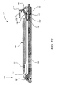
- FIG. 12 is a cross-sectional view of a demountably attachable cartridge of a linear stapling and cutting surgical instrument, in accordance with many embodiments.
- FIG. 13A is a partial perspective view of staple deployment related components of a demountably attachable cartridge of a linear stapling and cutting surgical instrument having four rows of staples, in accordance with many embodiments.
- FIG. 13B is a perspective view of a drive member of the cartridge of FIG. 13A .
- FIG. 13C includes perspective views of a staple pusher of the cartridge of FIG. 13A .
- FIG. 14A shows a distal end of a housing of the cartridge of FIG. 7 .
- FIG. 14B includes perspective views of a staple pusher of the cartridge of FIG. 7 .
- FIG. 14C is a perspective view of a drive member of the cartridge of FIG. 7 .
- FIG. 14D is a plan view of the drive member of the cartridge of FIG. 7 .
- FIG. 14E is a side view of the drive member of the cartridge of FIG. 7 .
- FIG. 14F is a distal end view of the drive member of the cartridge of FIG. 7 .
- FIG. 14G shows cross section AA of the drive member of the cartridge of FIG. 7 as defined in FIG. 14D .
- FIG. 14H shows cross section BB of the drive member of the cartridge of FIG. 7 as defined in FIG. 14D .
- FIG. 15A is a perspective view of a knife member of the cartridge of FIG. 7 .
- FIG. 15B is a side view of the knife member of the cartridge of FIG. 7 .
- FIG. 15C is a plan view of the knife member of the cartridge of FIG. 7 .
- FIGS. 15D through 15G respectively show partial side views of knife members, in accordance with many embodiments.
- FIG. 15H shows a top view of knife member, in accordance with many embodiments.
- FIG. 16A illustrates the actuation of the knife member of the cartridge of FIG. 7 .
- FIG. 16B shows a housing receptacle that receives a protrusion of the knife member to restrain the knife member from moving distally during a movement of the drive member distally, in accordance with many embodiments.
- FIG. 16C shows the knife member coupled with the drive member while the drive member drives the knife member distally, in accordance with many embodiments.
- FIG. 16D shows the knife member at the end of the actuation stroke after the distal end of the knife member has been driven along a cam surface of the housing to raise the distal end of the knife to lower the cutting blade of the knife into the housing, in accordance with many embodiments.
- FIG. 16E shows the knife member in a predetermined parked position of the distal garage, in accordance with many embodiments.
- FIG. 17 lists acts of a method of deploying staples from and of articulating a cutting blade in a linear stapling and cutting surgical instrument, in accordance with many embodiments.
- FIG. 1 is a plan view illustration of a Minimally Invasive Robotic Surgical (MIRS) system 10 , typically used for performing a minimally invasive diagnostic or surgical procedure on a Patient 12 who is lying down on an Operating table 14 .
- the system can include a Surgeon's Console 16 for use by a Surgeon 18 during the procedure.
- One or more Assistants 20 may also participate in the procedure.
- the MIRS system 10 can further include a Patient Side Cart 22 (surgical robot) and an Electronics Cart 24 .
- the Patient Side Cart 22 can manipulate at least one removably coupled tool assembly 26 (hereinafter simply referred to as a “tool”) through a minimally invasive incision in the body of the Patient 12 while the Surgeon 18 views the surgical site through the Console 16 .
- An image of the surgical site can be obtained by an endoscope 28 , such as a stereoscopic endoscope, which can be manipulated by the Patient Side Cart 22 to orient the endoscope 28 .
- the Electronics Cart 24 can be used to process the images of the surgical site for subsequent display to the Surgeon 18 through the Surgeon's Console 16 .
- the number of surgical tools 26 used at one time will generally depend on the diagnostic or surgical procedure and the space constraints within the operating room among other factors. If it is necessary to change one or more of the tools 26 being used during a procedure, an Assistant 20 may remove the tool 26 from the Patient Side Cart 22 , and replace it with another tool 26 from a tray 30 in the operating room.
- FIG. 2 is a perspective view of the Surgeon's Console 16 .
- the Surgeon's Console 16 includes a left eye display 32 and a right eye display 34 for presenting the Surgeon 18 with a coordinated stereo view of the surgical site that enables depth perception.
- the Console 16 further includes one or more input control devices 36 , which in turn cause the Patient Side Cart 22 (shown in FIG. 1 ) to manipulate one or more tools.
- the input control devices 36 can provide the same degrees of freedom as their associated tools 26 (shown in FIG. 1 ) to provide the Surgeon with telepresence, or the perception that the input control devices 36 are integral with the tools 26 so that the Surgeon has a strong sense of directly controlling the tools 26 .
- position, force, and tactile feedback sensors may be employed to transmit position, force, and tactile sensations from the tools 26 back to the Surgeon's hands through the input control devices 36 .
- the Surgeon's Console 16 is usually located in the same room as the patient so that the Surgeon may directly monitor the procedure, be physically present if necessary, and speak to an Assistant directly rather than over the telephone or other communication medium. However, the Surgeon can be located in a different room, a completely different building, or other remote location from the Patient allowing for remote surgical procedures.
- FIG. 3 is a perspective view of the Electronics Cart 24 .
- the Electronics Cart 24 can be coupled with the endoscope 28 and can include a processor to process captured images for subsequent display, such as to a Surgeon on the Surgeon's Console, or on another suitable display located locally and/or remotely.
- the Electronics Cart 24 can process the captured images to present the Surgeon with coordinated stereo images of the surgical site.
- Such coordination can include alignment between the opposing images and can include adjusting the stereo working distance of the stereoscopic endoscope.
- image processing can include the use of previously determined camera calibration parameters to compensate for imaging errors of the image capture device, such as optical aberrations.
- FIG. 4 diagrammatically illustrates a robotic surgery system 50 (such as MIRS system 10 of FIG. 1 ).
- a Surgeon's Console 52 (such as Surgeon's Console 16 in FIG. 1 ) can be used by a Surgeon to control a Patient Side Cart (Surgical Robot) 54 (such as Patent Side Cart 22 in FIG. 1 ) during a minimally invasive procedure.
- the Patient Side Cart 54 can use an imaging device, such as a stereoscopic endoscope, to capture images of the procedure site and output the captured images to an Electronics Cart 56 (such as the Electronics Cart 24 in FIG. 1 ).
- the Electronics Cart 56 can process the captured images in a variety of ways prior to any subsequent display.
- the Electronics Cart 56 can overlay the captured images with a virtual control interface prior to displaying the combined images to the Surgeon via the Surgeon's Console 52 .
- the Patient Side Cart 54 can output the captured images for processing outside the Electronics Cart 56 .
- the Patient Side Cart 54 can output the captured images to a processor 58 , which can be used to process the captured images.
- the images can also be processed by a combination the Electronics Cart 56 and the processor 58 , which can be coupled together to process the captured images jointly, sequentially, and/or combinations thereof.
- One or more separate displays 60 can also be coupled with the processor 58 and/or the Electronics Cart 56 for local and/or remote display of images, such as images of the procedure site, or other related images.
- FIGS. 5A and 5B show a Patient Side Cart 22 and a surgical tool 62 , respectively.
- the surgical tool 62 is an example of the surgical tools 26 .
- the Patient Side Cart 22 shown provides for the manipulation of three surgical tools 26 and an imaging device 28 , such as a stereoscopic endoscope used for the capture of images of the site of the procedure. Manipulation is provided by robotic mechanisms having a number of robotic joints.
- the imaging device 28 and the surgical tools 26 can be positioned and manipulated through incisions in the patient so that a kinematic remote center is maintained at the incision to minimize the size of the incision.
- Images of the surgical site can include images of the distal ends of the surgical tools 26 when they are positioned within the field-of-view of the imaging device 28 .
- FIG. 6 shows a surgical tool 70 that includes a proximal chassis 72 , an instrument shaft 74 , and a distal end effector 76 having a jaw 78 that can be articulated to grip a patient tissue.
- the proximal chassis includes input couplers that are configured to interface with and be driven by corresponding output couplers of the Patient Side Cart 22 .
- the input couplers are drivingly coupled with drive shafts that are disposed within the instrument shaft 74 .
- the drive shafts are drivingly coupled with the end effector 76 .
- FIG. 7 shows a demountably attachable cartridge 100 of a linear stapling and cutting surgical instrument, in accordance with many embodiments.
- the cartridge 100 is configured to removably attach to a jaw of an end effector.
- the cartridge has a proximal end 102 that is attached to the jaw of the end effector and a distal end 104 disposed at a corresponding distal end of the jaw of the end effector.
- the cartridge 100 includes six rows of staple openings 106 , a longitudinal slot 108 , a proximal knife garage 110 , a distal knife garage 112 , and a rotational input 114 .
- a staple is disposed in each of the staple openings for deployment there from.
- the longitudinal slot 108 accommodates a cutting blade of a knife member (not shown) extending there from as the knife member is moved from the proximal knife garage 110 to the distal knife garage 112 .
- the staples are deployed starting at the cartridge proximal end 102 and proceeding to the cartridge distal end 104 .
- the cutting blade is moved to trail the stapling of the tissue to ensure that only fully stapled tissue is cut.
- FIG. 8 shows the cartridge 100 with an attached staple retainer 116 , which is removed prior to using the cartridge 100 .
- FIG. 9 is a cross-sectional view showing details of the attachment of the cartridge 100 to an end effector 118 , in accordance with many embodiments.
- the end effector 118 includes a lower jaw 120 , an upper jaw 122 , a two degree of freedom wrist 124 , a rotationally-driven clamping mechanism 126 , and a spring loaded coupling 128 .
- the lower jaw 120 is configured to accommodate and support the cartridge 100 , as well as position the cartridge 100 relative to the spring loaded coupling 128 .
- the upper jaw 122 is pivotally coupled with the lower jaw 120 to articulate relative to the lower jaw 120 to clamp tissue.
- the upper jaw 122 includes staple forming recesses configured and positioned relative to the staple openings 106 to form the staples into a “B” shape upon deployment of the staples.
- the two degree of freedom wrist 124 provides for attachment of the end effector 118 to an elongated instrument shaft 130 for articulation of the end effector 118 about two orthogonal axes relative to the instrument shaft 130 . Details of a suitable two degree of freedom wrist that can be used are disclosed in U.S. application Ser. No. 12/945,748, entitled “SURGICAL TOOL WITH A TWO DEGREE OF FREEDOM WRIST,” filed Nov. 12, 2010, the full disclosure of which is hereby incorporated herein by reference.
- the rotationally-driven clamping mechanism 126 actuates the upper jaw 122 relative to the lower jaw 120 to securely clamp tissue between the upper and lower jaws.
- the clamping mechanism 126 is rotationally driven by a first drive shaft 132 disposed internal to the instrument shaft 130 . Details of a suitable rotationally-driven clamping mechanism that can be used are disclosed in U.S. application Ser. No. 12/945,541, entitled “END EFFECTOR WITH REDUNDANT CLOSING MECHANISMS,” filed Nov. 12, 2010, the full disclosure of which is hereby incorporated herein by reference.
- the spring-loaded coupling 128 rotationally couples a lead screw 134 of the cartridge 100 with an extension shaft 136 , which is driven by a second drive shaft 138 disposed internal to the instrument shaft 130 .
- the spring-loaded coupling 128 includes a coil spring 140 and a coupling fitting 142 .
- the coupling fitting 142 employs a three-lobe spline receptacle that interfaces with three-sided external surfaces of the rotational input 114 and of the extension shaft 136 .
- the spring-loaded coupling 142 accommodates angular misalignment of the three-lobe spline that might occur when cartridge 100 is installed into end effector 118 .
- the spring-loaded coupling 142 fully engages the three-lobe spline when rotated into angular alignment.
- Rotation of the lead screw 134 is used to translate a drive member 144 of the cartridge 100 .
- the resulting motion of the drive member 144 is used to deploy the staples and to distally advance a knife member 146 of the cartridge 100 to cut the clamped tissue down the center of the rows of deployed staples.
- the end effector 118 includes a first universal joint assembly 148 and a second universal joint assembly 150 .
- the first universal joint assembly 148 rotationally couples the clamping mechanism 126 to the first drive shaft 132 .
- the second universal joint assembly 150 rotationally couples the extension shaft 136 to the second drive shaft 138 .
- Each of the first and second universal joint assemblies 148 , 150 is configured to transmit torque through a range of angles suitable to the range of Pitch and Yaw of the end effector 118 relative to the instrument shaft 130 . Details of a suitable universal joint assembly that can be used are disclosed in U.S. application Ser. No. 12/945,740, entitled “DOUBLE UNIVERSAL JOINT,” filed Nov. 12, 2010, the full disclosure of which is hereby incorporated herein by reference.
- the first and second drive shafts 132 , 138 are disposed offset to the centerline of the instrument shaft 130 , which may be independently rotated. Details of a suitable drive mechanism that can be used to actuate the first and second drive shafts 132 , 138 are disclosed in U.S. application Ser. No. 12/945,461, entitled “MOTOR INTERFACE FOR PARALLEL DRIVE SHAFTS WITHIN AN INDEPENDENTLY ROTATING MEMBER,” filed Nov. 12, 2010, the full disclosure of which is hereby incorporated herein by reference.
- FIG. 10 is an exploded perspective view illustrating components of the cartridge 100 .
- the illustrated components include the retainer 116 , 66 staples 152 , a printed circuit assembly (PCA) spring 154 , a PCA 156 , a cartridge body 158 , 22 staple pushers 160 , the knife member 146 , the lead screw 134 , the drive member 144 , a thrust washer 162 , a lead screw nut 164 , and a cover 166 .
- the cartridge body 158 has the 66 staple openings 106 arranged in 6 rows, with 3 rows of the staple openings 106 being disposed on each side of the longitudinal slot 108 .
- the retainer 116 is removably attachable to the cartridge 100 and covers the staple openings 106 to retain the staples 152 prior to use of the cartridge 100 .
- the staple pushers 160 interface with the staples 152 and slidingly interface with the cartridge body 158 . Motion of the drive member 144 along the lead screw 134 results in engagement of the staple pushers 160 by distally-facing ramp surfaces 176 of the drive member 144 to drive the staple pushers 160 up relative to the cartridge body 158 to deploy the staples 152 as the drive member 144 moves towards the distal end 104 .
- the knife member 146 includes proximal protrusions 168 and distal protrusions 170 .
- the cover 166 is attached to the cartridge body 158 .
- FIGS. 11A and 11B further illustrate the PCA 156 and the PCA spring 154 .
- the PCA spring 154 interfaces with the cartridge body 158 and retains the PCA 156 .
- the PCA spring 154 includes PCA spring hooks 172 , which latch onto the cartridge body 158 to retain the PCA spring 154 .
- instrument pins 174 of the end effector 118 slide beneath and lift the PCA 156 , thereby electrically connecting the PCA 156 with the instrument pins 174 and allowing for the use of increased associated tolerances.
- This arrangement however is not critical, as long as the instrument pins 174 make suitable contact with the PCA 156 .
- the PCA 156 can be turned on edge such that the shown chip is out of the load path.
- the PCA 156 can be used to electronically store identification, configuration, and/or use information associated with the cartridge 100 .
- the cartridge 100 can be assembled using the following assembly sequence. First, with the cartridge body 158 in a “bottom up” orientation, the staple pushers 160 are installed into the staple openings 106 . Next, the knife member 146 is installed into the proximal garage 110 with proximal protrusions 168 of the knife member 146 placed into proximal receptacles in the cartridge body 158 . Next, the drive member 144 , the thrust washer 162 , and the lead screw nut 164 are installed onto the lead screw 134 and the lead screw nut 134 is laser welded flush to the end of the lead screw 134 .
- the resulting lead screw assembly is then installed into the cartridge body 158 with the drive member 144 positioned at the proximal end of the lead screw 134 .
- the cover 166 is installed onto the cartridge body 158 .
- the resulting assembly can then be lubricated, for example, by immersing the resulting assembly into a lubricant.
- the assembly is flipped to a “top up” orientation and the PCA 156 is installed.
- the PCA spring 154 is pushed onto the cartridge body 158 until the PCA spring hooks 172 latch.
- the staples 152 are installed into the staple openings 106 and the retainer 116 is then installed.
- data is installed into the PCA 156 .
- FIG. 12 illustrates components of the cartridge 100 related to the actuation of the knife member 146 from a starting position (illustrated) in which the knife member 146 is shielded by the proximal garage 110 to an ending position (not illustrated) in which the knife member 146 is shielded by the distal garage 112 .
- the lead screw 134 is mounted for rotation relative to the cartridge body 158 and extends along the length of the cartridge body 158 .
- the drive member 144 is internally threaded and is coupled with the lead screw 134 and slidably mounted in the cartridge body 158 for translation along the lead screw 134 in response to rotation of the lead screw 134 .
- the drive member 144 includes one or more distally-facing ramps 176 configured to engage the staple pushers 160 as the drive member 144 is advanced toward the distal end 104 of the cartridge body 100 .
- the knife member 146 includes a cutting blade 178 , the body portion 180 , the proximal protrusions 168 extending from opposite sides of the body portion 180 , and the proximal protrusions 170 also extending from opposite sides of the body portion 180 .
- the knife member 146 when the drive member 144 is advanced distally from its illustrated starting position, the knife member 146 remains stationary relative to the cartridge body 158 until the drive member 144 contacts the distal protrusions 170 by which the knife member 146 is then driven distally by the drive member 144 . Near the end of the distal travel of the drive member 144 , the distal end of the knife member 146 is driven along a cam surface 182 of the cartridge body 158 , thereby raising the distal end of the knife member 146 to lower the cutting blade 178 below an upper surface 184 of the cartridge body 158 and into the distal garage 112 .
- the knife member body portion 180 is constrained by opposing surfaces of the cartridge body 158 that define the longitudinal slot 108 .
- the knife proximal and distal protrusions 168 , 170 extend from opposite sides of the knife member body portion 180 beyond the width of the longitudinal slot 108 , thereby serving to constrain the knife member 146 vertically relative to the cartridge body 158 and the drive member 144 .
- FIGS. 13A through 13C show staple deployment related components of a linear stapling and cutting surgical instrument having four rows of staples, in accordance with many embodiments.
- an internally-threaded drive member 144 - 4 is coupled with a lead screw 134 and slidably mounted in a cartridge body (not shown) for translation along the lead screw 134 in response to rotation of the lead screw 134 .
- the drive member 144 - 4 includes distally facing bi-linear ramps 176 - 4 , which engage staple pushers 160 - 4 as the drive member 144 - 4 is advanced distally along the lead screw 134 .
- Each of the staple pushers 160 - 4 is configured to push a single staple (not shown).
- Each of the staple pushers 160 - 4 has bi-linear ramp surfaces 186 - 6 , which are configured to interface with the correspondingly sloped bi-linear ramps 176 - 4 of the drive member 144 - 4 .
- Each of the staple pushers 160 - 4 has end portions 188 - 4 that are shaped to slidingly interface with staple openings in the cartridge body.
- the drive member 144 - 4 is configured to accommodate and interface with the knife member 146 to initially move distally relative to the knife member 146 , then drive the knife member 146 toward the distal end of the cartridge body and push the distal end of the knife member 146 up the distal ramp 182 of the cartridge body 158 .
- the drive member 144 - 4 features that interface with the knife member 146 include a central slot 190 , proximal receptacles 192 , top surfaces 194 , and distal surfaces 196 .
- the central slot 190 accommodates the knife body portion 180 throughout the stroke of the knife member 146 from its starting position in the proximal garage 110 to its ending position in the distal garage 112 .
- the proximal receptacles 192 accommodate the knife member proximal protrusions 168 while the knife member 146 is driven distally by the drive member 144 - 4 .
- the top surfaces 194 interface with the proximal protrusions 168 to secure engagement between the proximal protrusions 168 and receptacles in the cartridge body 158 during the initial distal movement of the drive member 144 - 4 in which the drive member 144 - 4 is moved distally relative to both the cartridge body 158 and the knife member 146 and the knife member 146 is held stationary relative to the cartridge body 158 via the engagement between the proximal protrusions 168 and the associated cartridge body receptacles.
- the drive member distal surfaces 196 interface with the knife member distal protrusions 170 to drive the knife member 146 distally and, in conjunction with surfaces of the cartridge body 158 on both sides of the longitudinal slot 108 , control the vertical position of the distal protrusions 170 as the knife member 146 is driven distally.
- the distal protrusions 170 separate from the distal surfaces 196 and the knife member 146 is then driven by a proximal wall of the drive member proximal receptacles 192 , which interface with the knife member proximal protrusions 168 to drive the knife member 146 along the cam surface 182 , thereby stowing the cutting blade 178 into the distal garage 112 .
- FIG. 14A shows a distal end of the cartridge body 158 .
- FIG. 14B shows a top view and a perspective view of one of the staple pushers 160 .
- the staple openings 106 and the staple pushers 160 have complementary shapes such that each of the staple pushers 160 is accommodated within one of the staple openings 106 for translation within the staple opening 106 in response to being driven by the drive member 144 as the drive member 144 is translated toward the cartridge distal end 104 .
- FIGS. 14C through 14H provide additional illustration of the drive member 144 .
- FIG. 14C shows a perspective view of the drive member 144 .
- FIG. 14D shows a top view of the drive member 144 .
- FIG. 14E shows a side view of the drive member 144 .
- FIG. 14F shows a distal end view of the drive member 144 .
- FIG. 14G shows cross-sectional view AA as defined in FIG. 14D .
- FIG. 14H shows cross-sectional view BB as defined in FIG. 14D .
- FIGS. 15A through 15C provide additional illustration of the knife member 146 .
- the cutting blade 178 is faulted integral to the knife member body portion 180 .
- the proximal protrusions 168 and the distal protrusions 170 can be integral with the knife member body portion 180 , or formed by press-fitting pins into transverse holes in the knife-member body portion 180 .
- the body portion 180 and the pins can be formed from a suitable material(s), for example, 17-4 PH, 440A, 420 or 465 stainless steels.
- the cutting blade 178 is beveled to a ground edge on both sides, but can be flat with a ground edge, or beveled only on one side while ground on the other. Additional honing can be performed to create multiple angles on each side of the cutting blade 178 .
- the configuration of the knife member 146 provides robust support of the cutting blade 178 , which may be particularly advantageous when the cutting blade 178 is used to cut through something other than soft tissue. For example, it may occur that the cartridge 100 is used to deploy staples through previously stapled tissue, thereby possibly placing an existing staple in the path of the cutting blade 178 so that the existing staple must be cut ⁇ or dragged> by the cutting blade 178 .
- FIG. 15D illustrates an alternative configuration of the knife member 146 .
- the knife member has a cutting blade 178 with a hooked tip 179 .
- the hooked tip is blunted and protrudes well distally past, and well laterally above, the top-most cutting edge of the cutting blade.
- the hooked tip 179 can help ensure that a full thickness of tissue is cut by preventing tissue from climbing over the height of the cutting blade 178 .
- the hooked tip can also reduce the risk of injury to operating room staff in case a device failure leaves the cutting blade 178 exposed.
- FIG. 15E illustrates another alternative configuration of the knife member 146 .
- the knife member has a cutting blade 178 with a blunted tip 181 .
- the blunted tip protrudes slightly distally past (or is collinear with), but well laterally above, the top-most cutting edge of the cutting blade 179 .
- the blunted tip 181 of cutting blade 179 can help prevent tissue climb-over and reduce risk of accidental injury.
- FIG. 15F illustrates another alternative configuration of the knife member 146 .
- the knife member has a curved cutting blade 183 with a blunted tip.
- the blunted tip protrudes slightly distally past (or is collinear with), but well laterally above, the top-most cutting edge of the cutting blade 183 .
- the blunted tip of curved cutting blade 183 can help prevent tissue climb-over and reduce risk of accidental injury.
- the curved cutting blade 183 can also help further that purpose by gathering and centering tissue within its center-most portion. This can also help prevent tissue from clogging the lower-most blade/cartridge interface via the centering action.
- the cutting blade 183 is beveled to a ground edge on both sides, but can be flat with a ground edge, or beveled only on one side while ground on the other. Additional honing can be performed to create multiple angles on each side of the cutting blade 183 .
- FIG. 15G illustrates another alternative configuration of the knife member 146 .
- the knife member has a curved cutting blade 185 , which is largely identical to the curved cutting blade 183 of FIG. 15F , and thus shares the same features.
- the curved cutting blade 185 does not include a blunted tip, since in some applications the curvature of the cutting blade 185 alone can prevent tissue from climbing-over.
- FIG. 15H illustrates another alternative configuration of the knife member 146 .
- the knife member 146 is formed with integral pins 187 extending laterally on one side.
- the pins 187 respectively provide male coupling surfaces for attaching the knife member 146 to other portions of the cartridge 100 in a similar manner to pins 168 and 170 of FIG. 15C .
- the pins 187 can be formed, for example, by: stamping a singular piece of source material to form the knife member 146 integrally with the pins 187 ; welding/pressing/bonding the pins 187 into a separate knife member 146 ; or by molding (with additional forging as needed) the knife member 146 integrally with the pins 187 .
- the pins 187 can also extend from both sides of the knife member 146 , on the side opposite as shown, or the pins can extend from each side of the knife member 146 at different or the same proximal and distal portions of the knife member 146 .
- Indented surfaces 189 forming blind holes may also be formed opposite the pins by the above processes or later machined into the knife member.
- the indented surfaces 189 respectively provide female coupling surfaces for attaching the knife member 146 to other portions of the cartridge 100 . It should be understood that this pin configuration can apply to any of the blade designs disclosed herein.
- FIGS. 16A through 16D illustrate the interaction of components of the cartridge 100 during the actuation of the knife member 146 from its starting position in the proximal garage 110 to its final position in the distal garage 112 .
- FIG. 16A shows three different positions of the knife member 146 relative to the cartridge body 158 , specifically a starting proximal-most position, an intermediate position, and a distal position just before the distal end of the knife member 146 is driven up the cartridge body cam surface 182 .
- the drive member 144 is positioned at the proximal end of the lead screw 134 and the knife member proximal protrusions 168 are disposed within receptacles 198 in the cartridge body 158 .
- the drive member upper surfaces 194 interface with the knife member proximal protrusions 168 to retain the proximal protrusions 168 in the cartridge body receptacles 198 , thereby securing engagement between the proximal protrusions 168 and the cartridge body receptacles 198 .
- the knife member distal protrusions 170 and the distal end of the knife are trapped between a central cavity ceiling 200 of the cartridge body 158 and the lead screw 134 and the knife member body portion 180 is disposed within the longitudinal slot 108 , thereby restraining the knife member 146 in a substantially fixed position and orientation relative to the cartridge body 158 .
- the drive member proximal receptacles 192 are disposed below the cartridge body receptacles 198 , thereby permitting the knife member 146 to rotate to transfer the proximal protrusions 168 from the cartridge body receptacles 198 to the drive member proximal receptacles 192 .
- a distal surface 202 of the cartridge body receptacles 198 is sloped as illustrated to enhance the transfer by imparting a downward force component on the proximal protrusions 168 as the knife member distal surfaces 196 drive the knife member 146 distally via contact with the knife member distal protrusions 170 .
- FIG. 16C illustrates interaction between the drive member 144 , the knife member 146 , and the cartridge body 158 following the “lost motion” portion of the distal motion of the drive member 144 along the lead screw 134 .
- FIGS. 16A and 16D illustrate interaction between the drive member 144 , the knife member 146 , and the cartridge body 158 (particularly the cam surface 182 of the cartridge body 158 ) during a terminal portion of the distal motion of the drive member 144 along the lead screw 134 .
- the drive member 144 is advanced distally near the end of its travel along the lead screw 134 , the distal end of the knife member 146 comes into contact with the cam surface 182 and is subsequently driven along the cam surface 182 until reaching the ending distal-most position illustrated in FIG. 16D in which the drive member 144 has reached the end of its travel along the lead screw 134 .
- the knife member 146 rotates approximately around the knife member proximal protrusions 168 , thereby lowering the cutting blade 178 into the distal garage 112 .
- FIG. 16E illustrates the relationship between the knife member 146 and the cartridge body 158 , after the reaching the ending distal-most position illustrated in FIG. 16D .
- the knife member 146 is moved by the drive member 144 into a predetermined parked position within the distal garage 112 .
- a lower portion of the knife member 146 is unexposed within the cartridge body 158 , while an upper portion 204 that includes the tip remains displaced above upper surface 206 .
- all cutting edges of the upper portion of the knife member 146 are laterally protected from accidental touching by the distal garage 112 .
- the distal garage has lateral surfaces 208 , here forming a notch, that prevent users from inadvertent cuts when removing the cartridge 100 or otherwise handling the cartridge 100 . This is accomplished by surrounding all cutting edges of the upper portion 204 with lateral surfaces 208 of the distal garage 112 . Additionally, the lateral surfaces 208 of the garage 112 that face the upper portion of the knife member 146 are spaced far enough (more than the maximum diameter of the staple wire e.g., 0.25 mm) from the knife member 146 to accommodate a dislodged staple in between. Additional spacing is provided in the distal-most portion of the lateral surfaces, which causes the lateral surfaces to resemble a key pattern when viewed from above.
- the additional distal spacing allows for a pinched diameter of a staple that becomes lodged between the knife member 146 and the lateral surfaces 208 (and thus forcibly pinched as the knife member is brought fully into the predetermined parked position). In this manner, a dislodged staple can “wrap” around the knife member 146 .
- the lateral surfaces 208 of the distal garage 112 can diverge at an angle ranging from 25-45° to form a V or U shaped notch.
- the diverging lateral surfaces 208 are spaced apart wider, with respect to the longitudinal slot 108 , at their proximal-most gap as compared to the more distal locations. This gap allows cutting edge of the knife member 146 to apply significant bending force to a staple that bridges the proximal-most gap as the staple is brought into contact with the proximal-most gap by the knife member 146 , whereas a lesser gap may result in a jam.
- the distal garage 112 also includes at least one staple ejecting surface 210 .
- the staple ejecting surface 210 is formed as symmetrical ramped surfaces that are transverse to the lateral surfaces 208 , resembling a chamfer.
- An imaginary planar extension of the staple ejecting surface 210 is non-parallel with the upper surface 206 of the cartridge body and forms an angle with respect to the upper surface 206 ranging from 30-60°.
- the staple ejecting surface can cause a captured staple to move upwardly along the cutting edge of the knife member 146 as the knife member 146 is moved distally, thus, in some cases ejecting the staple as the staple is pushed over the top of the knife member 146 .
- FIG. 17 shows acts of a method 212 for deploying stables from, and of articulating a cutting blade in, a linear stapling and cutting surgical instrument, in accordance with many embodiments.
- Any suitable linear stapling and cutting surgical instrument can be used to practice the method 212 .
- the linear stapling and cutting surgical instruments and cartridges described herein can be used to practice the method 212 .
- a knife member having a cutting blade is supported within a housing of a linear stapling and cutting surgical instrument.
- the housing has a proximal end and a distal end.
- the cutting blade is configured to cut when the knife member is moved distally.
- a drive member is moved distally from the proximal end of the housing to the distal end of the housing such that the cutting blade becomes exposed.
- a plurality of staples exits the upper surface.
- the knife member is placed into a predetermined parked position at the distal end of the housing. In this position, a first portion of the cutting blade is made to displace below the upper surface. A second portion of the cutting blade remains above the upper surface, but is laterally faced by a garage that extends above the upper surface. There is enough lateral clearance in the predetermined parked position to accommodate a dislodged staple that may be forcibly placed between the knife member and the lateral surfaces.
- the methods disclosed herein can be employed in any suitable application.
- the methods disclosed herein can be employed in surgical instruments, manual or powered, hand-held or robotic, directly controlled or teleoperated, for open or minimally invasive (single or multi-port) procedures.
- force is to be construed as encompassing both force and torque (especially in the context of the following claims), unless otherwise indicated herein or clearly contradicted by context.
- the use of the terms “a” and “an” and “the” and similar referents in the context of describing the invention (especially in the context of the following claims) are to be construed to cover both the singular and the plural, unless otherwise indicated herein or clearly contradicted by context.
- the terms “comprising,” “having,” “including,” and “containing” are to be construed as open-ended terms (i.e., meaning “including, but not limited to,”) unless otherwise noted.
Abstract
Description
Claims (35)
Priority Applications (3)
| Application Number | Priority Date | Filing Date | Title |
|---|---|---|---|
| US14/145,855 US9498215B2 (en) | 2012-12-31 | 2013-12-31 | Surgical staple cartridge with enhanced knife clearance |
| US15/279,814 US10194908B2 (en) | 2012-12-31 | 2016-09-29 | Surgical staple cartridge with enhanced knife clearance |
| US16/238,397 US10918387B2 (en) | 2012-12-31 | 2019-01-02 | Surgical staple cartridge with enhanced knife clearance |
Applications Claiming Priority (2)
| Application Number | Priority Date | Filing Date | Title |
|---|---|---|---|
| US201261747970P | 2012-12-31 | 2012-12-31 | |
| US14/145,855 US9498215B2 (en) | 2012-12-31 | 2013-12-31 | Surgical staple cartridge with enhanced knife clearance |
Related Child Applications (1)
| Application Number | Title | Priority Date | Filing Date |
|---|---|---|---|
| US15/279,814 Continuation US10194908B2 (en) | 2012-12-31 | 2016-09-29 | Surgical staple cartridge with enhanced knife clearance |
Publications (2)
| Publication Number | Publication Date |
|---|---|
| US20140183244A1 US20140183244A1 (en) | 2014-07-03 |
| US9498215B2 true US9498215B2 (en) | 2016-11-22 |
Family
ID=51015995
Family Applications (3)
| Application Number | Title | Priority Date | Filing Date |
|---|---|---|---|
| US14/145,855 Active 2035-04-06 US9498215B2 (en) | 2012-12-31 | 2013-12-31 | Surgical staple cartridge with enhanced knife clearance |
| US15/279,814 Active 2034-06-30 US10194908B2 (en) | 2012-12-31 | 2016-09-29 | Surgical staple cartridge with enhanced knife clearance |
| US16/238,397 Active US10918387B2 (en) | 2012-12-31 | 2019-01-02 | Surgical staple cartridge with enhanced knife clearance |
Family Applications After (2)
| Application Number | Title | Priority Date | Filing Date |
|---|---|---|---|
| US15/279,814 Active 2034-06-30 US10194908B2 (en) | 2012-12-31 | 2016-09-29 | Surgical staple cartridge with enhanced knife clearance |
| US16/238,397 Active US10918387B2 (en) | 2012-12-31 | 2019-01-02 | Surgical staple cartridge with enhanced knife clearance |
Country Status (6)
| Country | Link |
|---|---|
| US (3) | US9498215B2 (en) |
| EP (1) | EP2938273A4 (en) |
| JP (3) | JP6297060B2 (en) |
| KR (1) | KR102194979B1 (en) |
| CN (2) | CN107518926B (en) |
| WO (1) | WO2014106275A1 (en) |
Cited By (144)
| Publication number | Priority date | Publication date | Assignee | Title |
|---|---|---|---|---|
| US20170209143A1 (en) * | 2013-12-31 | 2017-07-27 | Suzhou Touchstone International Medical Science Co., Ltd. | Linear cutting stapler |
| US9924941B2 (en) | 2011-10-26 | 2018-03-27 | Intuitive Surgical Operations, Inc. | Surgical instrument with integral knife blade |
| US10194908B2 (en) | 2012-12-31 | 2019-02-05 | Intuitive Surgical Operations, Inc. | Surgical staple cartridge with enhanced knife clearance |
| US10213203B2 (en) | 2015-08-26 | 2019-02-26 | Ethicon Llc | Staple cartridge assembly without a bottom cover |
| US10226251B2 (en) | 2015-10-15 | 2019-03-12 | Ethicon Llc | Surgical staple actuating sled with actuation stroke having minimized distance relative to distal staple |
| US10265065B2 (en) | 2013-12-23 | 2019-04-23 | Ethicon Llc | Surgical staples and staple cartridges |
| US10265069B2 (en) | 2015-10-15 | 2019-04-23 | Ethicon Llc | Surgical staple cartridge with varying staple crown width along a curve |
| USD847989S1 (en) | 2016-06-24 | 2019-05-07 | Ethicon Llc | Surgical fastener cartridge |
| USD850617S1 (en) | 2016-06-24 | 2019-06-04 | Ethicon Llc | Surgical fastener cartridge |
| US10314587B2 (en) | 2015-09-02 | 2019-06-11 | Ethicon Llc | Surgical staple cartridge with improved staple driver configurations |
| US10342535B2 (en) | 2015-10-15 | 2019-07-09 | Ethicon Llc | Method of applying staples to liver and other organs |
| US10499917B2 (en) | 2015-10-15 | 2019-12-10 | Ethicon Llc | Surgical stapler end effector with knife position indicators |
| US10537324B2 (en) | 2016-12-21 | 2020-01-21 | Ethicon Llc | Stepped staple cartridge with asymmetrical staples |
| US10542979B2 (en) | 2016-06-24 | 2020-01-28 | Ethicon Llc | Stamped staples and staple cartridges using the same |
| US10610223B2 (en) | 2011-11-15 | 2020-04-07 | Intuitive Surgical Operations, Inc. | Surgical instrument with stowing knife blade |
| US10687810B2 (en) | 2016-12-21 | 2020-06-23 | Ethicon Llc | Stepped staple cartridge with tissue retention and gap setting features |
| USD894389S1 (en) | 2016-06-24 | 2020-08-25 | Ethicon Llc | Surgical fastener |
| US10898622B2 (en) | 2017-12-28 | 2021-01-26 | Ethicon Llc | Surgical evacuation system with a communication circuit for communication between a filter and a smoke evacuation device |
| US10925599B2 (en) | 2013-12-23 | 2021-02-23 | Ethicon Llc | Modular surgical instruments |
| US10932806B2 (en) | 2017-10-30 | 2021-03-02 | Ethicon Llc | Reactive algorithm for surgical system |
| US10932872B2 (en) | 2017-12-28 | 2021-03-02 | Ethicon Llc | Cloud-based medical analytics for linking of local usage trends with the resource acquisition behaviors of larger data set |
| US10944728B2 (en) | 2017-12-28 | 2021-03-09 | Ethicon Llc | Interactive surgical systems with encrypted communication capabilities |
| US10943454B2 (en) | 2017-12-28 | 2021-03-09 | Ethicon Llc | Detection and escalation of security responses of surgical instruments to increasing severity threats |
| US10945727B2 (en) | 2016-12-21 | 2021-03-16 | Ethicon Llc | Staple cartridge with deformable driver retention features |
| US10952730B2 (en) | 2015-10-15 | 2021-03-23 | Ethicon Llc | End effector for surgical stapler with varying curve and taper |
| US10966791B2 (en) | 2017-12-28 | 2021-04-06 | Ethicon Llc | Cloud-based medical analytics for medical facility segmented individualization of instrument function |
| US10987178B2 (en) | 2017-12-28 | 2021-04-27 | Ethicon Llc | Surgical hub control arrangements |
| US10993715B2 (en) | 2016-12-21 | 2021-05-04 | Ethicon Llc | Staple cartridge comprising staples with different clamping breadths |
| US11013563B2 (en) | 2017-12-28 | 2021-05-25 | Ethicon Llc | Drive arrangements for robot-assisted surgical platforms |
| US11020109B2 (en) | 2013-12-23 | 2021-06-01 | Ethicon Llc | Surgical stapling assembly for use with a powered surgical interface |
| US11026687B2 (en) | 2017-10-30 | 2021-06-08 | Cilag Gmbh International | Clip applier comprising clip advancing systems |
| US11026751B2 (en) | 2017-12-28 | 2021-06-08 | Cilag Gmbh International | Display of alignment of staple cartridge to prior linear staple line |
| US11056244B2 (en) | 2017-12-28 | 2021-07-06 | Cilag Gmbh International | Automated data scaling, alignment, and organizing based on predefined parameters within surgical networks |
| US11051876B2 (en) | 2017-12-28 | 2021-07-06 | Cilag Gmbh International | Surgical evacuation flow paths |
| US11058498B2 (en) * | 2017-12-28 | 2021-07-13 | Cilag Gmbh International | Cooperative surgical actions for robot-assisted surgical platforms |
| US11069012B2 (en) | 2017-12-28 | 2021-07-20 | Cilag Gmbh International | Interactive surgical systems with condition handling of devices and data capabilities |
| US11076921B2 (en) | 2017-12-28 | 2021-08-03 | Cilag Gmbh International | Adaptive control program updates for surgical hubs |
| US11090047B2 (en) | 2018-03-28 | 2021-08-17 | Cilag Gmbh International | Surgical instrument comprising an adaptive control system |
| US11096693B2 (en) | 2017-12-28 | 2021-08-24 | Cilag Gmbh International | Adjustment of staple height of at least one row of staples based on the sensed tissue thickness or force in closing |
| US11100631B2 (en) | 2017-12-28 | 2021-08-24 | Cilag Gmbh International | Use of laser light and red-green-blue coloration to determine properties of back scattered light |
| US11096688B2 (en) | 2018-03-28 | 2021-08-24 | Cilag Gmbh International | Rotary driven firing members with different anvil and channel engagement features |
| US11114195B2 (en) | 2017-12-28 | 2021-09-07 | Cilag Gmbh International | Surgical instrument with a tissue marking assembly |
| US11109866B2 (en) | 2017-12-28 | 2021-09-07 | Cilag Gmbh International | Method for circular stapler control algorithm adjustment based on situational awareness |
| US11123065B2 (en) | 2013-12-23 | 2021-09-21 | Cilag Gmbh International | Surgical cutting and stapling instruments with independent jaw control features |
| US11129611B2 (en) | 2018-03-28 | 2021-09-28 | Cilag Gmbh International | Surgical staplers with arrangements for maintaining a firing member thereof in a locked configuration unless a compatible cartridge has been installed therein |
| US11132462B2 (en) | 2017-12-28 | 2021-09-28 | Cilag Gmbh International | Data stripping method to interrogate patient records and create anonymized record |
| US11141159B2 (en) | 2015-10-15 | 2021-10-12 | Cilag Gmbh International | Surgical stapler end effector with multi-staple driver crossing center line |
| US11147607B2 (en) | 2017-12-28 | 2021-10-19 | Cilag Gmbh International | Bipolar combination device that automatically adjusts pressure based on energy modality |
| US11160605B2 (en) | 2017-12-28 | 2021-11-02 | Cilag Gmbh International | Surgical evacuation sensing and motor control |
| US11166772B2 (en) | 2017-12-28 | 2021-11-09 | Cilag Gmbh International | Surgical hub coordination of control and communication of operating room devices |
| US11179208B2 (en) | 2017-12-28 | 2021-11-23 | Cilag Gmbh International | Cloud-based medical analytics for security and authentication trends and reactive measures |
| US11179204B2 (en) | 2017-12-28 | 2021-11-23 | Cilag Gmbh International | Wireless pairing of a surgical device with another device within a sterile surgical field based on the usage and situational awareness of devices |
| US11179175B2 (en) | 2017-12-28 | 2021-11-23 | Cilag Gmbh International | Controlling an ultrasonic surgical instrument according to tissue location |
| US11202570B2 (en) | 2017-12-28 | 2021-12-21 | Cilag Gmbh International | Communication hub and storage device for storing parameters and status of a surgical device to be shared with cloud based analytics systems |
| US11207067B2 (en) | 2018-03-28 | 2021-12-28 | Cilag Gmbh International | Surgical stapling device with separate rotary driven closure and firing systems and firing member that engages both jaws while firing |
| US11213295B2 (en) | 2015-09-02 | 2022-01-04 | Cilag Gmbh International | Surgical staple configurations with camming surfaces located between portions supporting surgical staples |
| US11219453B2 (en) | 2018-03-28 | 2022-01-11 | Cilag Gmbh International | Surgical stapling devices with cartridge compatible closure and firing lockout arrangements |
| US11219456B2 (en) | 2015-08-26 | 2022-01-11 | Cilag Gmbh International | Surgical staple strips for permitting varying staple properties and enabling easy cartridge loading |
| US11229436B2 (en) | 2017-10-30 | 2022-01-25 | Cilag Gmbh International | Surgical system comprising a surgical tool and a surgical hub |
| US11234756B2 (en) | 2017-12-28 | 2022-02-01 | Cilag Gmbh International | Powered surgical tool with predefined adjustable control algorithm for controlling end effector parameter |
| US11257589B2 (en) | 2017-12-28 | 2022-02-22 | Cilag Gmbh International | Real-time analysis of comprehensive cost of all instrumentation used in surgery utilizing data fluidity to track instruments through stocking and in-house processes |
| US11253315B2 (en) | 2017-12-28 | 2022-02-22 | Cilag Gmbh International | Increasing radio frequency to create pad-less monopolar loop |
| US11259806B2 (en) | 2018-03-28 | 2022-03-01 | Cilag Gmbh International | Surgical stapling devices with features for blocking advancement of a camming assembly of an incompatible cartridge installed therein |
| US11259830B2 (en) | 2018-03-08 | 2022-03-01 | Cilag Gmbh International | Methods for controlling temperature in ultrasonic device |
| US11259807B2 (en) | 2019-02-19 | 2022-03-01 | Cilag Gmbh International | Staple cartridges with cam surfaces configured to engage primary and secondary portions of a lockout of a surgical stapling device |
| US11266468B2 (en) | 2017-12-28 | 2022-03-08 | Cilag Gmbh International | Cooperative utilization of data derived from secondary sources by intelligent surgical hubs |
| US20220071633A1 (en) * | 2016-10-11 | 2022-03-10 | Intuitive Surgical Operations, Inc. | Stapler Cartridge With an Integral Knife |
| US11273001B2 (en) | 2017-12-28 | 2022-03-15 | Cilag Gmbh International | Surgical hub and modular device response adjustment based on situational awareness |
| US11278281B2 (en) | 2017-12-28 | 2022-03-22 | Cilag Gmbh International | Interactive surgical system |
| US11278280B2 (en) | 2018-03-28 | 2022-03-22 | Cilag Gmbh International | Surgical instrument comprising a jaw closure lockout |
| US11284936B2 (en) | 2017-12-28 | 2022-03-29 | Cilag Gmbh International | Surgical instrument having a flexible electrode |
| US11291495B2 (en) | 2017-12-28 | 2022-04-05 | Cilag Gmbh International | Interruption of energy due to inadvertent capacitive coupling |
| US11291510B2 (en) | 2017-10-30 | 2022-04-05 | Cilag Gmbh International | Method of hub communication with surgical instrument systems |
| US11298148B2 (en) | 2018-03-08 | 2022-04-12 | Cilag Gmbh International | Live time tissue classification using electrical parameters |
| US11304699B2 (en) | 2017-12-28 | 2022-04-19 | Cilag Gmbh International | Method for adaptive control schemes for surgical network control and interaction |
| US11304745B2 (en) | 2017-12-28 | 2022-04-19 | Cilag Gmbh International | Surgical evacuation sensing and display |
| US11308075B2 (en) | 2017-12-28 | 2022-04-19 | Cilag Gmbh International | Surgical network, instrument, and cloud responses based on validation of received dataset and authentication of its source and integrity |
| US11304763B2 (en) | 2017-12-28 | 2022-04-19 | Cilag Gmbh International | Image capturing of the areas outside the abdomen to improve placement and control of a surgical device in use |
| US11304720B2 (en) | 2017-12-28 | 2022-04-19 | Cilag Gmbh International | Activation of energy devices |
| US11311342B2 (en) | 2017-10-30 | 2022-04-26 | Cilag Gmbh International | Method for communicating with surgical instrument systems |
| US11311306B2 (en) | 2017-12-28 | 2022-04-26 | Cilag Gmbh International | Surgical systems for detecting end effector tissue distribution irregularities |
| US11317915B2 (en) | 2019-02-19 | 2022-05-03 | Cilag Gmbh International | Universal cartridge based key feature that unlocks multiple lockout arrangements in different surgical staplers |
| US11317937B2 (en) | 2018-03-08 | 2022-05-03 | Cilag Gmbh International | Determining the state of an ultrasonic end effector |
| US11317919B2 (en) | 2017-10-30 | 2022-05-03 | Cilag Gmbh International | Clip applier comprising a clip crimping system |
| USD950728S1 (en) | 2019-06-25 | 2022-05-03 | Cilag Gmbh International | Surgical staple cartridge |
| US11324557B2 (en) | 2017-12-28 | 2022-05-10 | Cilag Gmbh International | Surgical instrument with a sensing array |
| USD952144S1 (en) | 2019-06-25 | 2022-05-17 | Cilag Gmbh International | Surgical staple cartridge retainer with firing system authentication key |
| US11337746B2 (en) | 2018-03-08 | 2022-05-24 | Cilag Gmbh International | Smart blade and power pulsing |
| US11357503B2 (en) | 2019-02-19 | 2022-06-14 | Cilag Gmbh International | Staple cartridge retainers with frangible retention features and methods of using same |
| US11364075B2 (en) | 2017-12-28 | 2022-06-21 | Cilag Gmbh International | Radio frequency energy device for delivering combined electrical signals |
| US11369377B2 (en) | 2019-02-19 | 2022-06-28 | Cilag Gmbh International | Surgical stapling assembly with cartridge based retainer configured to unlock a firing lockout |
| US11376002B2 (en) | 2017-12-28 | 2022-07-05 | Cilag Gmbh International | Surgical instrument cartridge sensor assemblies |
| US11389164B2 (en) | 2017-12-28 | 2022-07-19 | Cilag Gmbh International | Method of using reinforced flexible circuits with multiple sensors to optimize performance of radio frequency devices |
| US11410259B2 (en) | 2017-12-28 | 2022-08-09 | Cilag Gmbh International | Adaptive control program updates for surgical devices |
| US11424027B2 (en) | 2017-12-28 | 2022-08-23 | Cilag Gmbh International | Method for operating surgical instrument systems |
| US11423007B2 (en) | 2017-12-28 | 2022-08-23 | Cilag Gmbh International | Adjustment of device control programs based on stratified contextual data in addition to the data |
| US11419630B2 (en) | 2017-12-28 | 2022-08-23 | Cilag Gmbh International | Surgical system distributed processing |
| US11419667B2 (en) | 2017-12-28 | 2022-08-23 | Cilag Gmbh International | Ultrasonic energy device which varies pressure applied by clamp arm to provide threshold control pressure at a cut progression location |
| US11432885B2 (en) | 2017-12-28 | 2022-09-06 | Cilag Gmbh International | Sensing arrangements for robot-assisted surgical platforms |
| USD964564S1 (en) | 2019-06-25 | 2022-09-20 | Cilag Gmbh International | Surgical staple cartridge retainer with a closure system authentication key |
| US11446052B2 (en) | 2017-12-28 | 2022-09-20 | Cilag Gmbh International | Variation of radio frequency and ultrasonic power level in cooperation with varying clamp arm pressure to achieve predefined heat flux or power applied to tissue |
| US11464511B2 (en) | 2019-02-19 | 2022-10-11 | Cilag Gmbh International | Surgical staple cartridges with movable authentication key arrangements |
| US11464535B2 (en) | 2017-12-28 | 2022-10-11 | Cilag Gmbh International | Detection of end effector emersion in liquid |
| US11464559B2 (en) | 2017-12-28 | 2022-10-11 | Cilag Gmbh International | Estimating state of ultrasonic end effector and control system therefor |
| US11471156B2 (en) | 2018-03-28 | 2022-10-18 | Cilag Gmbh International | Surgical stapling devices with improved rotary driven closure systems |
| US11504192B2 (en) | 2014-10-30 | 2022-11-22 | Cilag Gmbh International | Method of hub communication with surgical instrument systems |
| US11510741B2 (en) | 2017-10-30 | 2022-11-29 | Cilag Gmbh International | Method for producing a surgical instrument comprising a smart electrical system |
| US11517325B2 (en) | 2017-06-20 | 2022-12-06 | Cilag Gmbh International | Closed loop feedback control of motor velocity of a surgical stapling and cutting instrument based on measured displacement distance traveled over a specified time interval |
| US11529187B2 (en) | 2017-12-28 | 2022-12-20 | Cilag Gmbh International | Surgical evacuation sensor arrangements |
| US11540855B2 (en) | 2017-12-28 | 2023-01-03 | Cilag Gmbh International | Controlling activation of an ultrasonic surgical instrument according to the presence of tissue |
| US11559308B2 (en) | 2017-12-28 | 2023-01-24 | Cilag Gmbh International | Method for smart energy device infrastructure |
| US11559307B2 (en) | 2017-12-28 | 2023-01-24 | Cilag Gmbh International | Method of robotic hub communication, detection, and control |
| US11564756B2 (en) | 2017-10-30 | 2023-01-31 | Cilag Gmbh International | Method of hub communication with surgical instrument systems |
| US11571234B2 (en) | 2017-12-28 | 2023-02-07 | Cilag Gmbh International | Temperature control of ultrasonic end effector and control system therefor |
| US11576677B2 (en) | 2017-12-28 | 2023-02-14 | Cilag Gmbh International | Method of hub communication, processing, display, and cloud analytics |
| US11576738B2 (en) | 2018-10-08 | 2023-02-14 | Auris Health, Inc. | Systems and instruments for tissue sealing |
| US11589888B2 (en) | 2017-12-28 | 2023-02-28 | Cilag Gmbh International | Method for controlling smart energy devices |
| US11589932B2 (en) | 2017-12-28 | 2023-02-28 | Cilag Gmbh International | Usage and technique analysis of surgeon / staff performance against a baseline to optimize device utilization and performance for both current and future procedures |
| US11601371B2 (en) | 2017-12-28 | 2023-03-07 | Cilag Gmbh International | Surgical network determination of prioritization of communication, interaction, or processing based on system or device needs |
| US11596291B2 (en) | 2017-12-28 | 2023-03-07 | Cilag Gmbh International | Method of compressing tissue within a stapling device and simultaneously displaying of the location of the tissue within the jaws |
| US11602393B2 (en) | 2017-12-28 | 2023-03-14 | Cilag Gmbh International | Surgical evacuation sensing and generator control |
| US11612444B2 (en) | 2017-12-28 | 2023-03-28 | Cilag Gmbh International | Adjustment of a surgical device function based on situational awareness |
| US11659023B2 (en) | 2017-12-28 | 2023-05-23 | Cilag Gmbh International | Method of hub communication |
| US11666331B2 (en) | 2017-12-28 | 2023-06-06 | Cilag Gmbh International | Systems for detecting proximity of surgical end effector to cancerous tissue |
| US11684367B2 (en) | 2016-12-21 | 2023-06-27 | Cilag Gmbh International | Stepped assembly having and end-of-life indicator |
| US11690619B2 (en) | 2016-06-24 | 2023-07-04 | Cilag Gmbh International | Staple cartridge comprising staples having different geometries |
| US11696760B2 (en) | 2017-12-28 | 2023-07-11 | Cilag Gmbh International | Safety systems for smart powered surgical stapling |
| US11744604B2 (en) | 2017-12-28 | 2023-09-05 | Cilag Gmbh International | Surgical instrument with a hardware-only control circuit |
| US11771487B2 (en) | 2017-12-28 | 2023-10-03 | Cilag Gmbh International | Mechanisms for controlling different electromechanical systems of an electrosurgical instrument |
| US11786245B2 (en) | 2017-12-28 | 2023-10-17 | Cilag Gmbh International | Surgical systems with prioritized data transmission capabilities |
| US11786251B2 (en) | 2017-12-28 | 2023-10-17 | Cilag Gmbh International | Method for adaptive control schemes for surgical network control and interaction |
| US11801098B2 (en) | 2017-10-30 | 2023-10-31 | Cilag Gmbh International | Method of hub communication with surgical instrument systems |
| US11818052B2 (en) | 2017-12-28 | 2023-11-14 | Cilag Gmbh International | Surgical network determination of prioritization of communication, interaction, or processing based on system or device needs |
| US11832899B2 (en) | 2017-12-28 | 2023-12-05 | Cilag Gmbh International | Surgical systems with autonomously adjustable control programs |
| US11832840B2 (en) | 2017-12-28 | 2023-12-05 | Cilag Gmbh International | Surgical instrument having a flexible circuit |
| US11857152B2 (en) | 2017-12-28 | 2024-01-02 | Cilag Gmbh International | Surgical hub spatial awareness to determine devices in operating theater |
| US11864728B2 (en) | 2017-12-28 | 2024-01-09 | Cilag Gmbh International | Characterization of tissue irregularities through the use of mono-chromatic light refractivity |
| US11871901B2 (en) | 2012-05-20 | 2024-01-16 | Cilag Gmbh International | Method for situational awareness for surgical network or surgical network connected device capable of adjusting function based on a sensed situation or usage |
| US11896322B2 (en) | 2017-12-28 | 2024-02-13 | Cilag Gmbh International | Sensing the patient position and contact utilizing the mono-polar return pad electrode to provide situational awareness to the hub |
| US11896443B2 (en) | 2017-12-28 | 2024-02-13 | Cilag Gmbh International | Control of a surgical system through a surgical barrier |
| US11903601B2 (en) | 2017-12-28 | 2024-02-20 | Cilag Gmbh International | Surgical instrument comprising a plurality of drive systems |
| US11911045B2 (en) | 2017-10-30 | 2024-02-27 | Cllag GmbH International | Method for operating a powered articulating multi-clip applier |
| US11937769B2 (en) | 2017-12-28 | 2024-03-26 | Cilag Gmbh International | Method of hub communication, processing, storage and display |
| US11950776B2 (en) | 2022-03-04 | 2024-04-09 | Cilag Gmbh International | Modular surgical instruments |
Families Citing this family (365)
| Publication number | Priority date | Publication date | Assignee | Title |
|---|---|---|---|---|
| US9060770B2 (en) | 2003-05-20 | 2015-06-23 | Ethicon Endo-Surgery, Inc. | Robotically-driven surgical instrument with E-beam driver |
| US20070084897A1 (en) | 2003-05-20 | 2007-04-19 | Shelton Frederick E Iv | Articulating surgical stapling instrument incorporating a two-piece e-beam firing mechanism |
| US11896225B2 (en) | 2004-07-28 | 2024-02-13 | Cilag Gmbh International | Staple cartridge comprising a pan |
| US8215531B2 (en) | 2004-07-28 | 2012-07-10 | Ethicon Endo-Surgery, Inc. | Surgical stapling instrument having a medical substance dispenser |
| US7669746B2 (en) | 2005-08-31 | 2010-03-02 | Ethicon Endo-Surgery, Inc. | Staple cartridges for forming staples having differing formed staple heights |
| US7934630B2 (en) | 2005-08-31 | 2011-05-03 | Ethicon Endo-Surgery, Inc. | Staple cartridges for forming staples having differing formed staple heights |
| US9237891B2 (en) | 2005-08-31 | 2016-01-19 | Ethicon Endo-Surgery, Inc. | Robotically-controlled surgical stapling devices that produce formed staples having different lengths |
| US10159482B2 (en) | 2005-08-31 | 2018-12-25 | Ethicon Llc | Fastener cartridge assembly comprising a fixed anvil and different staple heights |
| US11484312B2 (en) | 2005-08-31 | 2022-11-01 | Cilag Gmbh International | Staple cartridge comprising a staple driver arrangement |
| US11246590B2 (en) | 2005-08-31 | 2022-02-15 | Cilag Gmbh International | Staple cartridge including staple drivers having different unfired heights |
| US20070106317A1 (en) | 2005-11-09 | 2007-05-10 | Shelton Frederick E Iv | Hydraulically and electrically actuated articulation joints for surgical instruments |
| US20110024477A1 (en) | 2009-02-06 | 2011-02-03 | Hall Steven G | Driven Surgical Stapler Improvements |
| US7753904B2 (en) | 2006-01-31 | 2010-07-13 | Ethicon Endo-Surgery, Inc. | Endoscopic surgical instrument with a handle that can articulate with respect to the shaft |
| US20110290856A1 (en) | 2006-01-31 | 2011-12-01 | Ethicon Endo-Surgery, Inc. | Robotically-controlled surgical instrument with force-feedback capabilities |
| US11278279B2 (en) | 2006-01-31 | 2022-03-22 | Cilag Gmbh International | Surgical instrument assembly |
| US7845537B2 (en) | 2006-01-31 | 2010-12-07 | Ethicon Endo-Surgery, Inc. | Surgical instrument having recording capabilities |
| US8186555B2 (en) | 2006-01-31 | 2012-05-29 | Ethicon Endo-Surgery, Inc. | Motor-driven surgical cutting and fastening instrument with mechanical closure system |
| US8820603B2 (en) | 2006-01-31 | 2014-09-02 | Ethicon Endo-Surgery, Inc. | Accessing data stored in a memory of a surgical instrument |
| US11224427B2 (en) | 2006-01-31 | 2022-01-18 | Cilag Gmbh International | Surgical stapling system including a console and retraction assembly |
| US20120292367A1 (en) | 2006-01-31 | 2012-11-22 | Ethicon Endo-Surgery, Inc. | Robotically-controlled end effector |
| US11793518B2 (en) | 2006-01-31 | 2023-10-24 | Cilag Gmbh International | Powered surgical instruments with firing system lockout arrangements |
| US8708213B2 (en) | 2006-01-31 | 2014-04-29 | Ethicon Endo-Surgery, Inc. | Surgical instrument having a feedback system |
| US8992422B2 (en) | 2006-03-23 | 2015-03-31 | Ethicon Endo-Surgery, Inc. | Robotically-controlled endoscopic accessory channel |
| US8322455B2 (en) | 2006-06-27 | 2012-12-04 | Ethicon Endo-Surgery, Inc. | Manually driven surgical cutting and fastening instrument |
| US10568652B2 (en) | 2006-09-29 | 2020-02-25 | Ethicon Llc | Surgical staples having attached drivers of different heights and stapling instruments for deploying the same |
| US11291441B2 (en) | 2007-01-10 | 2022-04-05 | Cilag Gmbh International | Surgical instrument with wireless communication between control unit and remote sensor |
| US8652120B2 (en) | 2007-01-10 | 2014-02-18 | Ethicon Endo-Surgery, Inc. | Surgical instrument with wireless communication between control unit and sensor transponders |
| US8684253B2 (en) | 2007-01-10 | 2014-04-01 | Ethicon Endo-Surgery, Inc. | Surgical instrument with wireless communication between a control unit of a robotic system and remote sensor |
| US11039836B2 (en) | 2007-01-11 | 2021-06-22 | Cilag Gmbh International | Staple cartridge for use with a surgical stapling instrument |
| US8701958B2 (en) | 2007-01-11 | 2014-04-22 | Ethicon Endo-Surgery, Inc. | Curved end effector for a surgical stapling device |
| US8727197B2 (en) | 2007-03-15 | 2014-05-20 | Ethicon Endo-Surgery, Inc. | Staple cartridge cavity configuration with cooperative surgical staple |
| US8931682B2 (en) | 2007-06-04 | 2015-01-13 | Ethicon Endo-Surgery, Inc. | Robotically-controlled shaft based rotary drive systems for surgical instruments |
| US11672531B2 (en) | 2007-06-04 | 2023-06-13 | Cilag Gmbh International | Rotary drive systems for surgical instruments |
| US7753245B2 (en) | 2007-06-22 | 2010-07-13 | Ethicon Endo-Surgery, Inc. | Surgical stapling instruments |
| US11849941B2 (en) | 2007-06-29 | 2023-12-26 | Cilag Gmbh International | Staple cartridge having staple cavities extending at a transverse angle relative to a longitudinal cartridge axis |
| US8636736B2 (en) | 2008-02-14 | 2014-01-28 | Ethicon Endo-Surgery, Inc. | Motorized surgical cutting and fastening instrument |
| US9179912B2 (en) | 2008-02-14 | 2015-11-10 | Ethicon Endo-Surgery, Inc. | Robotically-controlled motorized surgical cutting and fastening instrument |
| US7866527B2 (en) | 2008-02-14 | 2011-01-11 | Ethicon Endo-Surgery, Inc. | Surgical stapling apparatus with interlockable firing system |
| US7819298B2 (en) | 2008-02-14 | 2010-10-26 | Ethicon Endo-Surgery, Inc. | Surgical stapling apparatus with control features operable with one hand |
| BRPI0901282A2 (en) | 2008-02-14 | 2009-11-17 | Ethicon Endo Surgery Inc | surgical cutting and fixation instrument with rf electrodes |
| US8573465B2 (en) | 2008-02-14 | 2013-11-05 | Ethicon Endo-Surgery, Inc. | Robotically-controlled surgical end effector system with rotary actuated closure systems |
| US9615826B2 (en) | 2010-09-30 | 2017-04-11 | Ethicon Endo-Surgery, Llc | Multiple thickness implantable layers for surgical stapling devices |
| US8210411B2 (en) | 2008-09-23 | 2012-07-03 | Ethicon Endo-Surgery, Inc. | Motor-driven surgical cutting instrument |
| US11648005B2 (en) | 2008-09-23 | 2023-05-16 | Cilag Gmbh International | Robotically-controlled motorized surgical instrument with an end effector |
| US9386983B2 (en) | 2008-09-23 | 2016-07-12 | Ethicon Endo-Surgery, Llc | Robotically-controlled motorized surgical instrument |
| US9005230B2 (en) | 2008-09-23 | 2015-04-14 | Ethicon Endo-Surgery, Inc. | Motorized surgical instrument |
| US8608045B2 (en) | 2008-10-10 | 2013-12-17 | Ethicon Endo-Sugery, Inc. | Powered surgical cutting and stapling apparatus with manually retractable firing system |
| US8517239B2 (en) | 2009-02-05 | 2013-08-27 | Ethicon Endo-Surgery, Inc. | Surgical stapling instrument comprising a magnetic element driver |
| JP2012517287A (en) | 2009-02-06 | 2012-08-02 | エシコン・エンド−サージェリィ・インコーポレイテッド | Improvement of driven surgical stapler |
| US8851354B2 (en) | 2009-12-24 | 2014-10-07 | Ethicon Endo-Surgery, Inc. | Surgical cutting instrument that analyzes tissue thickness |
| US8783543B2 (en) | 2010-07-30 | 2014-07-22 | Ethicon Endo-Surgery, Inc. | Tissue acquisition arrangements and methods for surgical stapling devices |
| US9700317B2 (en) | 2010-09-30 | 2017-07-11 | Ethicon Endo-Surgery, Llc | Fastener cartridge comprising a releasable tissue thickness compensator |
| US11812965B2 (en) | 2010-09-30 | 2023-11-14 | Cilag Gmbh International | Layer of material for a surgical end effector |
| US9113865B2 (en) | 2010-09-30 | 2015-08-25 | Ethicon Endo-Surgery, Inc. | Staple cartridge comprising a layer |
| US9386988B2 (en) | 2010-09-30 | 2016-07-12 | Ethicon End-Surgery, LLC | Retainer assembly including a tissue thickness compensator |
| US11925354B2 (en) | 2010-09-30 | 2024-03-12 | Cilag Gmbh International | Staple cartridge comprising staples positioned within a compressible portion thereof |
| US11298125B2 (en) | 2010-09-30 | 2022-04-12 | Cilag Gmbh International | Tissue stapler having a thickness compensator |
| US9629814B2 (en) | 2010-09-30 | 2017-04-25 | Ethicon Endo-Surgery, Llc | Tissue thickness compensator configured to redistribute compressive forces |
| US10945731B2 (en) | 2010-09-30 | 2021-03-16 | Ethicon Llc | Tissue thickness compensator comprising controlled release and expansion |
| US9351730B2 (en) | 2011-04-29 | 2016-05-31 | Ethicon Endo-Surgery, Llc | Tissue thickness compensator comprising channels |
| US8695866B2 (en) | 2010-10-01 | 2014-04-15 | Ethicon Endo-Surgery, Inc. | Surgical instrument having a power control circuit |
| AU2012250197B2 (en) | 2011-04-29 | 2017-08-10 | Ethicon Endo-Surgery, Inc. | Staple cartridge comprising staples positioned within a compressible portion thereof |
| US9072535B2 (en) | 2011-05-27 | 2015-07-07 | Ethicon Endo-Surgery, Inc. | Surgical stapling instruments with rotatable staple deployment arrangements |
| US11207064B2 (en) | 2011-05-27 | 2021-12-28 | Cilag Gmbh International | Automated end effector component reloading system for use with a robotic system |
| BR112014024098B1 (en) | 2012-03-28 | 2021-05-25 | Ethicon Endo-Surgery, Inc. | staple cartridge |
| JP6305979B2 (en) | 2012-03-28 | 2018-04-04 | エシコン・エンド−サージェリィ・インコーポレイテッドEthicon Endo−Surgery,Inc. | Tissue thickness compensator with multiple layers |
| RU2644272C2 (en) | 2012-03-28 | 2018-02-08 | Этикон Эндо-Серджери, Инк. | Limitation node with tissue thickness compensator |
| US9101358B2 (en) | 2012-06-15 | 2015-08-11 | Ethicon Endo-Surgery, Inc. | Articulatable surgical instrument comprising a firing drive |
| US9408606B2 (en) | 2012-06-28 | 2016-08-09 | Ethicon Endo-Surgery, Llc | Robotically powered surgical device with manually-actuatable reversing system |
| BR112014032776B1 (en) | 2012-06-28 | 2021-09-08 | Ethicon Endo-Surgery, Inc | SURGICAL INSTRUMENT SYSTEM AND SURGICAL KIT FOR USE WITH A SURGICAL INSTRUMENT SYSTEM |
| US9289256B2 (en) | 2012-06-28 | 2016-03-22 | Ethicon Endo-Surgery, Llc | Surgical end effectors having angled tissue-contacting surfaces |
| US20140001231A1 (en) | 2012-06-28 | 2014-01-02 | Ethicon Endo-Surgery, Inc. | Firing system lockout arrangements for surgical instruments |
| US11202631B2 (en) | 2012-06-28 | 2021-12-21 | Cilag Gmbh International | Stapling assembly comprising a firing lockout |
| US9282974B2 (en) | 2012-06-28 | 2016-03-15 | Ethicon Endo-Surgery, Llc | Empty clip cartridge lockout |
| JP6290201B2 (en) | 2012-06-28 | 2018-03-07 | エシコン・エンド−サージェリィ・インコーポレイテッドEthicon Endo−Surgery,Inc. | Lockout for empty clip cartridge |
| BR112015021098B1 (en) | 2013-03-01 | 2022-02-15 | Ethicon Endo-Surgery, Inc | COVERAGE FOR A JOINT JOINT AND SURGICAL INSTRUMENT |
| RU2669463C2 (en) | 2013-03-01 | 2018-10-11 | Этикон Эндо-Серджери, Инк. | Surgical instrument with soft stop |
| US9629629B2 (en) | 2013-03-14 | 2017-04-25 | Ethicon Endo-Surgey, LLC | Control systems for surgical instruments |
| US10136887B2 (en) | 2013-04-16 | 2018-11-27 | Ethicon Llc | Drive system decoupling arrangement for a surgical instrument |
| BR112015026109B1 (en) | 2013-04-16 | 2022-02-22 | Ethicon Endo-Surgery, Inc | surgical instrument |
| US9924942B2 (en) | 2013-08-23 | 2018-03-27 | Ethicon Llc | Motor-powered articulatable surgical instruments |
| MX369362B (en) | 2013-08-23 | 2019-11-06 | Ethicon Endo Surgery Llc | Firing member retraction devices for powered surgical instruments. |
| EP3578119B1 (en) | 2013-12-11 | 2021-03-17 | Covidien LP | Wrist and jaw assemblies for robotic surgical systems |
| US9962161B2 (en) | 2014-02-12 | 2018-05-08 | Ethicon Llc | Deliverable surgical instrument |
| US9804618B2 (en) | 2014-03-26 | 2017-10-31 | Ethicon Llc | Systems and methods for controlling a segmented circuit |
| BR112016021943B1 (en) | 2014-03-26 | 2022-06-14 | Ethicon Endo-Surgery, Llc | SURGICAL INSTRUMENT FOR USE BY AN OPERATOR IN A SURGICAL PROCEDURE |
| JP6532889B2 (en) | 2014-04-16 | 2019-06-19 | エシコン エルエルシーEthicon LLC | Fastener cartridge assembly and staple holder cover arrangement |
| BR112016023825B1 (en) | 2014-04-16 | 2022-08-02 | Ethicon Endo-Surgery, Llc | STAPLE CARTRIDGE FOR USE WITH A SURGICAL STAPLER AND STAPLE CARTRIDGE FOR USE WITH A SURGICAL INSTRUMENT |
| CN106456176B (en) | 2014-04-16 | 2019-06-28 | 伊西康内外科有限责任公司 | Fastener cartridge including the extension with various configuration |
| US20150297222A1 (en) | 2014-04-16 | 2015-10-22 | Ethicon Endo-Surgery, Inc. | Fastener cartridges including extensions having different configurations |
| BR112017004361B1 (en) | 2014-09-05 | 2023-04-11 | Ethicon Llc | ELECTRONIC SYSTEM FOR A SURGICAL INSTRUMENT |
| US10135242B2 (en) | 2014-09-05 | 2018-11-20 | Ethicon Llc | Smart cartridge wake up operation and data retention |
| US11311294B2 (en) | 2014-09-05 | 2022-04-26 | Cilag Gmbh International | Powered medical device including measurement of closure state of jaws |
| US10105142B2 (en) * | 2014-09-18 | 2018-10-23 | Ethicon Llc | Surgical stapler with plurality of cutting elements |
| MX2017003960A (en) | 2014-09-26 | 2017-12-04 | Ethicon Llc | Surgical stapling buttresses and adjunct materials. |
| US11523821B2 (en) | 2014-09-26 | 2022-12-13 | Cilag Gmbh International | Method for creating a flexible staple line |
| US9924944B2 (en) | 2014-10-16 | 2018-03-27 | Ethicon Llc | Staple cartridge comprising an adjunct material |
| US11141153B2 (en) | 2014-10-29 | 2021-10-12 | Cilag Gmbh International | Staple cartridges comprising driver arrangements |
| US10517594B2 (en) | 2014-10-29 | 2019-12-31 | Ethicon Llc | Cartridge assemblies for surgical staplers |
| US9844376B2 (en) | 2014-11-06 | 2017-12-19 | Ethicon Llc | Staple cartridge comprising a releasable adjunct material |
| US10736636B2 (en) | 2014-12-10 | 2020-08-11 | Ethicon Llc | Articulatable surgical instrument system |
| US9844375B2 (en) | 2014-12-18 | 2017-12-19 | Ethicon Llc | Drive arrangements for articulatable surgical instruments |
| US9987000B2 (en) | 2014-12-18 | 2018-06-05 | Ethicon Llc | Surgical instrument assembly comprising a flexible articulation system |
| US10085748B2 (en) | 2014-12-18 | 2018-10-02 | Ethicon Llc | Locking arrangements for detachable shaft assemblies with articulatable surgical end effectors |
| US10004501B2 (en) | 2014-12-18 | 2018-06-26 | Ethicon Llc | Surgical instruments with improved closure arrangements |
| RU2703684C2 (en) | 2014-12-18 | 2019-10-21 | ЭТИКОН ЭНДО-СЕРДЖЕРИ, ЭлЭлСи | Surgical instrument with anvil which is selectively movable relative to staple cartridge around discrete fixed axis |
| US9844374B2 (en) | 2014-12-18 | 2017-12-19 | Ethicon Llc | Surgical instrument systems comprising an articulatable end effector and means for adjusting the firing stroke of a firing member |
| US10695142B2 (en) | 2015-02-19 | 2020-06-30 | Covidien Lp | Repositioning method of input device for robotic surgical system |
| US11154301B2 (en) | 2015-02-27 | 2021-10-26 | Cilag Gmbh International | Modular stapling assembly |
| US10441279B2 (en) | 2015-03-06 | 2019-10-15 | Ethicon Llc | Multiple level thresholds to modify operation of powered surgical instruments |
| US9993248B2 (en) | 2015-03-06 | 2018-06-12 | Ethicon Endo-Surgery, Llc | Smart sensors with local signal processing |
| JP2020121162A (en) | 2015-03-06 | 2020-08-13 | エシコン エルエルシーEthicon LLC | Time dependent evaluation of sensor data to determine stability element, creep element and viscoelastic element of measurement |
| US10052044B2 (en) | 2015-03-06 | 2018-08-21 | Ethicon Llc | Time dependent evaluation of sensor data to determine stability, creep, and viscoelastic elements of measures |
| US10245033B2 (en) | 2015-03-06 | 2019-04-02 | Ethicon Llc | Surgical instrument comprising a lockable battery housing |
| US10716639B2 (en) | 2015-03-10 | 2020-07-21 | Covidien Lp | Measuring health of a connector member of a robotic surgical system |
| US10390825B2 (en) | 2015-03-31 | 2019-08-27 | Ethicon Llc | Surgical instrument with progressive rotary drive systems |
| JP6714618B2 (en) | 2015-06-03 | 2020-06-24 | コヴィディエン リミテッド パートナーシップ | Offset instrument drive |
| WO2016205266A1 (en) | 2015-06-16 | 2016-12-22 | Covidien Lp | Robotic surgical system torque transduction sensing |
| EP3313315B1 (en) | 2015-06-23 | 2024-04-10 | Covidien LP | Robotic surgical assemblies |
| US11058425B2 (en) | 2015-08-17 | 2021-07-13 | Ethicon Llc | Implantable layers for a surgical instrument |
| JP6833820B2 (en) * | 2015-08-26 | 2021-02-24 | エシコン エルエルシーEthicon LLC | Staple cartridge assembly without bottom cover |
| US10238386B2 (en) | 2015-09-23 | 2019-03-26 | Ethicon Llc | Surgical stapler having motor control based on an electrical parameter related to a motor current |
| US10105139B2 (en) | 2015-09-23 | 2018-10-23 | Ethicon Llc | Surgical stapler having downstream current-based motor control |
| US10806454B2 (en) | 2015-09-25 | 2020-10-20 | Covidien Lp | Robotic surgical assemblies and instrument drive connectors thereof |
| US10299878B2 (en) | 2015-09-25 | 2019-05-28 | Ethicon Llc | Implantable adjunct systems for determining adjunct skew |
| US10980539B2 (en) | 2015-09-30 | 2021-04-20 | Ethicon Llc | Implantable adjunct comprising bonded layers |
| US11890015B2 (en) | 2015-09-30 | 2024-02-06 | Cilag Gmbh International | Compressible adjunct with crossing spacer fibers |
| US10561420B2 (en) | 2015-09-30 | 2020-02-18 | Ethicon Llc | Tubular absorbable constructs |
| US10285699B2 (en) | 2015-09-30 | 2019-05-14 | Ethicon Llc | Compressible adjunct |
| US10265073B2 (en) * | 2015-10-15 | 2019-04-23 | Ethicon Llc | Surgical stapler with terminal staple orientation crossing center line |
| WO2017070275A1 (en) | 2015-10-23 | 2017-04-27 | Covidien Lp | Surgical system for detecting gradual changes in perfusion |
| KR102597849B1 (en) | 2015-11-11 | 2023-11-03 | 인튜어티브 서지컬 오퍼레이션즈 인코포레이티드 | Reconfigurable end effector structure |
| WO2017087439A1 (en) | 2015-11-19 | 2017-05-26 | Covidien Lp | Optical force sensor for robotic surgical system |
| US10265068B2 (en) | 2015-12-30 | 2019-04-23 | Ethicon Llc | Surgical instruments with separable motors and motor control circuits |
| US10292704B2 (en) | 2015-12-30 | 2019-05-21 | Ethicon Llc | Mechanisms for compensating for battery pack failure in powered surgical instruments |
| US10368865B2 (en) | 2015-12-30 | 2019-08-06 | Ethicon Llc | Mechanisms for compensating for drivetrain failure in powered surgical instruments |
| US11213293B2 (en) | 2016-02-09 | 2022-01-04 | Cilag Gmbh International | Articulatable surgical instruments with single articulation link arrangements |
| BR112018016098B1 (en) | 2016-02-09 | 2023-02-23 | Ethicon Llc | SURGICAL INSTRUMENT |
| US11224426B2 (en) | 2016-02-12 | 2022-01-18 | Cilag Gmbh International | Mechanisms for compensating for drivetrain failure in powered surgical instruments |
| US10448948B2 (en) | 2016-02-12 | 2019-10-22 | Ethicon Llc | Mechanisms for compensating for drivetrain failure in powered surgical instruments |
| US10722233B2 (en) * | 2016-04-07 | 2020-07-28 | Intuitive Surgical Operations, Inc. | Stapling cartridge |
| US11576562B2 (en) | 2016-04-07 | 2023-02-14 | Titan Medical Inc. | Camera positioning method and apparatus for capturing images during a medical procedure |
| US10335145B2 (en) | 2016-04-15 | 2019-07-02 | Ethicon Llc | Modular surgical instrument with configurable operating mode |
| US10828028B2 (en) | 2016-04-15 | 2020-11-10 | Ethicon Llc | Surgical instrument with multiple program responses during a firing motion |
| US10492783B2 (en) | 2016-04-15 | 2019-12-03 | Ethicon, Llc | Surgical instrument with improved stop/start control during a firing motion |
| US10426467B2 (en) | 2016-04-15 | 2019-10-01 | Ethicon Llc | Surgical instrument with detection sensors |
| US11607239B2 (en) | 2016-04-15 | 2023-03-21 | Cilag Gmbh International | Systems and methods for controlling a surgical stapling and cutting instrument |
| US10456137B2 (en) | 2016-04-15 | 2019-10-29 | Ethicon Llc | Staple formation detection mechanisms |
| US10357247B2 (en) | 2016-04-15 | 2019-07-23 | Ethicon Llc | Surgical instrument with multiple program responses during a firing motion |
| US11179150B2 (en) | 2016-04-15 | 2021-11-23 | Cilag Gmbh International | Systems and methods for controlling a surgical stapling and cutting instrument |
| US11317917B2 (en) | 2016-04-18 | 2022-05-03 | Cilag Gmbh International | Surgical stapling system comprising a lockable firing assembly |
| US20170296173A1 (en) | 2016-04-18 | 2017-10-19 | Ethicon Endo-Surgery, Llc | Method for operating a surgical instrument |
| US10478181B2 (en) | 2016-04-18 | 2019-11-19 | Ethicon Llc | Cartridge lockout arrangements for rotary powered surgical cutting and stapling instruments |
| AU2017272075B2 (en) | 2016-05-26 | 2021-04-29 | Covidien Lp | Robotic surgical assemblies |
| US10736219B2 (en) | 2016-05-26 | 2020-08-04 | Covidien Lp | Instrument drive units |
| EP3463162A4 (en) | 2016-06-03 | 2020-06-24 | Covidien LP | Systems, methods, and computer-readable program products for controlling a robotically delivered manipulator |
| CN113180835A (en) | 2016-06-03 | 2021-07-30 | 柯惠Lp公司 | Control arm for robotic surgical system |
| CN114504387A (en) | 2016-06-03 | 2022-05-17 | 柯惠Lp公司 | Passive shaft system for robotic surgical system |
| US11553984B2 (en) | 2016-06-03 | 2023-01-17 | Covidien Lp | Robotic surgical system with an embedded imager |
| KR20220156673A (en) | 2016-09-09 | 2022-11-25 | 인튜어티브 서지컬 오퍼레이션즈 인코포레이티드 | Wrist architecture |
| US11166773B2 (en) | 2016-09-09 | 2021-11-09 | Intuitive Surgical Operations, Inc. | Stapler beam architecture |
| US10631857B2 (en) * | 2016-11-04 | 2020-04-28 | Covidien Lp | Loading unit for surgical instruments with low profile pushers |
| US11419606B2 (en) | 2016-12-21 | 2022-08-23 | Cilag Gmbh International | Shaft assembly comprising a clutch configured to adapt the output of a rotary firing member to two different systems |
| US11134942B2 (en) | 2016-12-21 | 2021-10-05 | Cilag Gmbh International | Surgical stapling instruments and staple-forming anvils |
| US20180168615A1 (en) | 2016-12-21 | 2018-06-21 | Ethicon Endo-Surgery, Llc | Method of deforming staples from two different types of staple cartridges with the same surgical stapling instrument |
| CN110099619B (en) | 2016-12-21 | 2022-07-15 | 爱惜康有限责任公司 | Lockout device for surgical end effector and replaceable tool assembly |
| US20180168625A1 (en) | 2016-12-21 | 2018-06-21 | Ethicon Endo-Surgery, Llc | Surgical stapling instruments with smart staple cartridges |
| US10517595B2 (en) | 2016-12-21 | 2019-12-31 | Ethicon Llc | Jaw actuated lock arrangements for preventing advancement of a firing member in a surgical end effector unless an unfired cartridge is installed in the end effector |
| JP7010956B2 (en) | 2016-12-21 | 2022-01-26 | エシコン エルエルシー | How to staple tissue |
| US10588632B2 (en) | 2016-12-21 | 2020-03-17 | Ethicon Llc | Surgical end effectors and firing members thereof |
| US10675025B2 (en) | 2016-12-21 | 2020-06-09 | Ethicon Llc | Shaft assembly comprising separately actuatable and retractable systems |
| BR112019011947A2 (en) | 2016-12-21 | 2019-10-29 | Ethicon Llc | surgical stapling systems |
| US10617414B2 (en) | 2016-12-21 | 2020-04-14 | Ethicon Llc | Closure member arrangements for surgical instruments |
| US10675026B2 (en) | 2016-12-21 | 2020-06-09 | Ethicon Llc | Methods of stapling tissue |
| US10588630B2 (en) | 2016-12-21 | 2020-03-17 | Ethicon Llc | Surgical tool assemblies with closure stroke reduction features |
| JP2020507377A (en) | 2017-02-15 | 2020-03-12 | コヴィディエン リミテッド パートナーシップ | Systems and equipment for crush prevention in medical robot applications |
| US11717361B2 (en) | 2017-05-24 | 2023-08-08 | Covidien Lp | Electrosurgical robotic system having tool presence detection |
| EP3629980A4 (en) | 2017-05-25 | 2021-03-10 | Covidien LP | Robotic surgical system with automated guidance |
| EP3629983B1 (en) | 2017-05-25 | 2023-06-28 | Covidien LP | Robotic surgical systems and drapes for covering components of robotic surgical systems |
| US11553974B2 (en) | 2017-05-25 | 2023-01-17 | Covidien Lp | Systems and methods for detection of objects within a field of view of an image capture device |
| US11090046B2 (en) | 2017-06-20 | 2021-08-17 | Cilag Gmbh International | Systems and methods for controlling displacement member motion of a surgical stapling and cutting instrument |
| US10779820B2 (en) | 2017-06-20 | 2020-09-22 | Ethicon Llc | Systems and methods for controlling motor speed according to user input for a surgical instrument |
| US11071554B2 (en) | 2017-06-20 | 2021-07-27 | Cilag Gmbh International | Closed loop feedback control of motor velocity of a surgical stapling and cutting instrument based on magnitude of velocity error measurements |
| US10881399B2 (en) | 2017-06-20 | 2021-01-05 | Ethicon Llc | Techniques for adaptive control of motor velocity of a surgical stapling and cutting instrument |
| US10307170B2 (en) | 2017-06-20 | 2019-06-04 | Ethicon Llc | Method for closed loop control of motor velocity of a surgical stapling and cutting instrument |
| US11382638B2 (en) | 2017-06-20 | 2022-07-12 | Cilag Gmbh International | Closed loop feedback control of motor velocity of a surgical stapling and cutting instrument based on measured time over a specified displacement distance |
| US11653914B2 (en) | 2017-06-20 | 2023-05-23 | Cilag Gmbh International | Systems and methods for controlling motor velocity of a surgical stapling and cutting instrument according to articulation angle of end effector |
| US20180368844A1 (en) | 2017-06-27 | 2018-12-27 | Ethicon Llc | Staple forming pocket arrangements |
| US11266405B2 (en) | 2017-06-27 | 2022-03-08 | Cilag Gmbh International | Surgical anvil manufacturing methods |
| US10993716B2 (en) | 2017-06-27 | 2021-05-04 | Ethicon Llc | Surgical anvil arrangements |
| US11324503B2 (en) | 2017-06-27 | 2022-05-10 | Cilag Gmbh International | Surgical firing member arrangements |
| US11678880B2 (en) | 2017-06-28 | 2023-06-20 | Cilag Gmbh International | Surgical instrument comprising a shaft including a housing arrangement |
| US11246592B2 (en) | 2017-06-28 | 2022-02-15 | Cilag Gmbh International | Surgical instrument comprising an articulation system lockable to a frame |
| US10765427B2 (en) | 2017-06-28 | 2020-09-08 | Ethicon Llc | Method for articulating a surgical instrument |
| EP3420947B1 (en) | 2017-06-28 | 2022-05-25 | Cilag GmbH International | Surgical instrument comprising selectively actuatable rotatable couplers |
| US11259805B2 (en) | 2017-06-28 | 2022-03-01 | Cilag Gmbh International | Surgical instrument comprising firing member supports |
| USD906355S1 (en) | 2017-06-28 | 2020-12-29 | Ethicon Llc | Display screen or portion thereof with a graphical user interface for a surgical instrument |
| US11020114B2 (en) | 2017-06-28 | 2021-06-01 | Cilag Gmbh International | Surgical instruments with articulatable end effector with axially shortened articulation joint configurations |
| US11564686B2 (en) | 2017-06-28 | 2023-01-31 | Cilag Gmbh International | Surgical shaft assemblies with flexible interfaces |
| US10932772B2 (en) | 2017-06-29 | 2021-03-02 | Ethicon Llc | Methods for closed loop velocity control for robotic surgical instrument |
| US11471155B2 (en) | 2017-08-03 | 2022-10-18 | Cilag Gmbh International | Surgical system bailout |
| US11944300B2 (en) | 2017-08-03 | 2024-04-02 | Cilag Gmbh International | Method for operating a surgical system bailout |
| US11304695B2 (en) | 2017-08-03 | 2022-04-19 | Cilag Gmbh International | Surgical system shaft interconnection |
| CN110177516B (en) | 2017-09-05 | 2023-10-24 | 柯惠Lp公司 | Collision handling algorithm for robotic surgical systems |
| JP2020533061A (en) | 2017-09-06 | 2020-11-19 | コヴィディエン リミテッド パートナーシップ | Boundary scaling of surgical robots |
| US11399829B2 (en) | 2017-09-29 | 2022-08-02 | Cilag Gmbh International | Systems and methods of initiating a power shutdown mode for a surgical instrument |
| US11134944B2 (en) | 2017-10-30 | 2021-10-05 | Cilag Gmbh International | Surgical stapler knife motion controls |
| US11090075B2 (en) | 2017-10-30 | 2021-08-17 | Cilag Gmbh International | Articulation features for surgical end effector |
| US10842490B2 (en) | 2017-10-31 | 2020-11-24 | Ethicon Llc | Cartridge body design with force reduction based on firing completion |
| US10863988B2 (en) | 2017-11-29 | 2020-12-15 | Intuitive Surgical Operations, Inc. | Surgical instrument with lockout mechanism |
| US10779826B2 (en) | 2017-12-15 | 2020-09-22 | Ethicon Llc | Methods of operating surgical end effectors |
| US11071543B2 (en) | 2017-12-15 | 2021-07-27 | Cilag Gmbh International | Surgical end effectors with clamping assemblies configured to increase jaw aperture ranges |
| US11197670B2 (en) | 2017-12-15 | 2021-12-14 | Cilag Gmbh International | Surgical end effectors with pivotal jaws configured to touch at their respective distal ends when fully closed |
| US10835330B2 (en) | 2017-12-19 | 2020-11-17 | Ethicon Llc | Method for determining the position of a rotatable jaw of a surgical instrument attachment assembly |
| US11020112B2 (en) | 2017-12-19 | 2021-06-01 | Ethicon Llc | Surgical tools configured for interchangeable use with different controller interfaces |
| US11311290B2 (en) | 2017-12-21 | 2022-04-26 | Cilag Gmbh International | Surgical instrument comprising an end effector dampener |
| US11179151B2 (en) | 2017-12-21 | 2021-11-23 | Cilag Gmbh International | Surgical instrument comprising a display |
| US11076853B2 (en) | 2017-12-21 | 2021-08-03 | Cilag Gmbh International | Systems and methods of displaying a knife position during transection for a surgical instrument |
| US11129680B2 (en) | 2017-12-21 | 2021-09-28 | Cilag Gmbh International | Surgical instrument comprising a projector |
| CN111556735A (en) | 2018-01-04 | 2020-08-18 | 柯惠Lp公司 | Systems and assemblies for mounting surgical accessories to robotic surgical systems and providing access therethrough |
| US11517312B2 (en) | 2018-02-12 | 2022-12-06 | Intuitive Surgical Operations, Inc. | Surgical instrument with lockout mechanism |
| WO2019165403A1 (en) | 2018-02-26 | 2019-08-29 | Intuitive Surgical, Inc. | Surgical instrument with lockout mechanism |
| US11189379B2 (en) | 2018-03-06 | 2021-11-30 | Digital Surgery Limited | Methods and systems for using multiple data structures to process surgical data |
| WO2019173056A1 (en) | 2018-03-08 | 2019-09-12 | Covidien Lp | Surgical robotic systems |
| US10973520B2 (en) * | 2018-03-28 | 2021-04-13 | Ethicon Llc | Surgical staple cartridge with firing member driven camming assembly that has an onboard tissue cutting feature |
| CN111989065A (en) | 2018-04-20 | 2020-11-24 | 柯惠Lp公司 | Compensation of observer movement in a robotic surgical system with a stereoscopic display |
| CN112105312A (en) | 2018-07-03 | 2020-12-18 | 柯惠Lp公司 | Systems, methods, and computer-readable media for detecting image degradation during a surgical procedure |
| US11045192B2 (en) | 2018-08-20 | 2021-06-29 | Cilag Gmbh International | Fabricating techniques for surgical stapler anvils |
| US11253256B2 (en) | 2018-08-20 | 2022-02-22 | Cilag Gmbh International | Articulatable motor powered surgical instruments with dedicated articulation motor arrangements |
| US11039834B2 (en) | 2018-08-20 | 2021-06-22 | Cilag Gmbh International | Surgical stapler anvils with staple directing protrusions and tissue stability features |
| US11083458B2 (en) | 2018-08-20 | 2021-08-10 | Cilag Gmbh International | Powered surgical instruments with clutching arrangements to convert linear drive motions to rotary drive motions |
| US11207065B2 (en) | 2018-08-20 | 2021-12-28 | Cilag Gmbh International | Method for fabricating surgical stapler anvils |
| USD914878S1 (en) | 2018-08-20 | 2021-03-30 | Ethicon Llc | Surgical instrument anvil |
| US11291440B2 (en) | 2018-08-20 | 2022-04-05 | Cilag Gmbh International | Method for operating a powered articulatable surgical instrument |
| US11324501B2 (en) | 2018-08-20 | 2022-05-10 | Cilag Gmbh International | Surgical stapling devices with improved closure members |
| US11109746B2 (en) | 2018-10-10 | 2021-09-07 | Titan Medical Inc. | Instrument insertion system, method, and apparatus for performing medical procedures |
| EP3897405A4 (en) | 2018-12-21 | 2022-09-14 | Intuitive Surgical Operations, Inc. | Actuation mechanisms for surgical instruments |
| JP7241178B2 (en) | 2018-12-21 | 2023-03-16 | インテュイティブ サージカル オペレーションズ, インコーポレイテッド | Surgical instrument with reinforced staple cartridge |
| US11857188B2 (en) | 2018-12-21 | 2024-01-02 | Intuitive Surgical Operations, Inc. | Articulation assemblies for surgical instruments |
| US11723661B2 (en) | 2018-12-21 | 2023-08-15 | Intuitive Surgical Operations, Inc. | Surgical instruments with switches for deactivating and/or identifying stapler cartridges |
| US11586106B2 (en) | 2018-12-28 | 2023-02-21 | Titan Medical Inc. | Imaging apparatus having configurable stereoscopic perspective |
| US11103245B2 (en) * | 2018-12-31 | 2021-08-31 | Cilag Gmbh International | Knife for surgical stapler and associated method of manufacture with MIM and hip |
| US11717355B2 (en) | 2019-01-29 | 2023-08-08 | Covidien Lp | Drive mechanisms for surgical instruments such as for use in robotic surgical systems |
| US11576733B2 (en) | 2019-02-06 | 2023-02-14 | Covidien Lp | Robotic surgical assemblies including electrosurgical instruments having articulatable wrist assemblies |
| CN113395939A (en) * | 2019-02-11 | 2021-09-14 | 柯惠有限合伙公司 | Shipping wedge for a staple cartridge |
| US11484372B2 (en) | 2019-02-15 | 2022-11-01 | Covidien Lp | Articulation mechanisms for surgical instruments such as for use in robotic surgical systems |
| US11147551B2 (en) | 2019-03-25 | 2021-10-19 | Cilag Gmbh International | Firing drive arrangements for surgical systems |
| US11172929B2 (en) | 2019-03-25 | 2021-11-16 | Cilag Gmbh International | Articulation drive arrangements for surgical systems |
| US11696761B2 (en) * | 2019-03-25 | 2023-07-11 | Cilag Gmbh International | Firing drive arrangements for surgical systems |
| US11147553B2 (en) | 2019-03-25 | 2021-10-19 | Cilag Gmbh International | Firing drive arrangements for surgical systems |
| WO2020214258A1 (en) | 2019-04-15 | 2020-10-22 | Intuitive Surgical Operations, Inc. | Staple cartridge for a surgical instrument |
| US11471157B2 (en) | 2019-04-30 | 2022-10-18 | Cilag Gmbh International | Articulation control mapping for a surgical instrument |
| US11648009B2 (en) | 2019-04-30 | 2023-05-16 | Cilag Gmbh International | Rotatable jaw tip for a surgical instrument |
| US11903581B2 (en) | 2019-04-30 | 2024-02-20 | Cilag Gmbh International | Methods for stapling tissue using a surgical instrument |
| US11426251B2 (en) | 2019-04-30 | 2022-08-30 | Cilag Gmbh International | Articulation directional lights on a surgical instrument |
| US11452528B2 (en) | 2019-04-30 | 2022-09-27 | Cilag Gmbh International | Articulation actuators for a surgical instrument |
| US11432816B2 (en) | 2019-04-30 | 2022-09-06 | Cilag Gmbh International | Articulation pin for a surgical instrument |
| US11253254B2 (en) | 2019-04-30 | 2022-02-22 | Cilag Gmbh International | Shaft rotation actuator on a surgical instrument |
| WO2020242808A1 (en) | 2019-05-31 | 2020-12-03 | Intuitive Surgical Operations, Inc. | Staple cartridge for a surgical instrument |
| US11229437B2 (en) | 2019-06-28 | 2022-01-25 | Cilag Gmbh International | Method for authenticating the compatibility of a staple cartridge with a surgical instrument |
| US11426167B2 (en) | 2019-06-28 | 2022-08-30 | Cilag Gmbh International | Mechanisms for proper anvil attachment surgical stapling head assembly |
| US11684434B2 (en) | 2019-06-28 | 2023-06-27 | Cilag Gmbh International | Surgical RFID assemblies for instrument operational setting control |
| US11627959B2 (en) | 2019-06-28 | 2023-04-18 | Cilag Gmbh International | Surgical instruments including manual and powered system lockouts |
| US11298127B2 (en) | 2019-06-28 | 2022-04-12 | Cilag GmbH Interational | Surgical stapling system having a lockout mechanism for an incompatible cartridge |
| US11219455B2 (en) | 2019-06-28 | 2022-01-11 | Cilag Gmbh International | Surgical instrument including a lockout key |
| US11361176B2 (en) | 2019-06-28 | 2022-06-14 | Cilag Gmbh International | Surgical RFID assemblies for compatibility detection |
| US11464601B2 (en) | 2019-06-28 | 2022-10-11 | Cilag Gmbh International | Surgical instrument comprising an RFID system for tracking a movable component |
| US11478241B2 (en) | 2019-06-28 | 2022-10-25 | Cilag Gmbh International | Staple cartridge including projections |
| US11853835B2 (en) | 2019-06-28 | 2023-12-26 | Cilag Gmbh International | RFID identification systems for surgical instruments |
| US11523822B2 (en) | 2019-06-28 | 2022-12-13 | Cilag Gmbh International | Battery pack including a circuit interrupter |
| US11553971B2 (en) | 2019-06-28 | 2023-01-17 | Cilag Gmbh International | Surgical RFID assemblies for display and communication |
| US11259803B2 (en) | 2019-06-28 | 2022-03-01 | Cilag Gmbh International | Surgical stapling system having an information encryption protocol |
| US11246678B2 (en) | 2019-06-28 | 2022-02-15 | Cilag Gmbh International | Surgical stapling system having a frangible RFID tag |
| US11497492B2 (en) | 2019-06-28 | 2022-11-15 | Cilag Gmbh International | Surgical instrument including an articulation lock |
| US11399837B2 (en) | 2019-06-28 | 2022-08-02 | Cilag Gmbh International | Mechanisms for motor control adjustments of a motorized surgical instrument |
| US11051807B2 (en) | 2019-06-28 | 2021-07-06 | Cilag Gmbh International | Packaging assembly including a particulate trap |
| US11298132B2 (en) | 2019-06-28 | 2022-04-12 | Cilag GmbH Inlernational | Staple cartridge including a honeycomb extension |
| US11224497B2 (en) | 2019-06-28 | 2022-01-18 | Cilag Gmbh International | Surgical systems with multiple RFID tags |
| US11376098B2 (en) | 2019-06-28 | 2022-07-05 | Cilag Gmbh International | Surgical instrument system comprising an RFID system |
| US11660163B2 (en) | 2019-06-28 | 2023-05-30 | Cilag Gmbh International | Surgical system with RFID tags for updating motor assembly parameters |
| US11291451B2 (en) | 2019-06-28 | 2022-04-05 | Cilag Gmbh International | Surgical instrument with battery compatibility verification functionality |
| US11771419B2 (en) | 2019-06-28 | 2023-10-03 | Cilag Gmbh International | Packaging for a replaceable component of a surgical stapling system |
| US11638587B2 (en) | 2019-06-28 | 2023-05-02 | Cilag Gmbh International | RFID identification systems for surgical instruments |
| US11786325B2 (en) | 2019-07-02 | 2023-10-17 | Intuitive Surgical Operations, Inc. | Remotely controlling a system using video |
| US11529139B2 (en) | 2019-12-19 | 2022-12-20 | Cilag Gmbh International | Motor driven surgical instrument |
| US11446029B2 (en) | 2019-12-19 | 2022-09-20 | Cilag Gmbh International | Staple cartridge comprising projections extending from a curved deck surface |
| US11234698B2 (en) | 2019-12-19 | 2022-02-01 | Cilag Gmbh International | Stapling system comprising a clamp lockout and a firing lockout |
| US11559304B2 (en) | 2019-12-19 | 2023-01-24 | Cilag Gmbh International | Surgical instrument comprising a rapid closure mechanism |
| US11504122B2 (en) | 2019-12-19 | 2022-11-22 | Cilag Gmbh International | Surgical instrument comprising a nested firing member |
| US11607219B2 (en) | 2019-12-19 | 2023-03-21 | Cilag Gmbh International | Staple cartridge comprising a detachable tissue cutting knife |
| US11576672B2 (en) | 2019-12-19 | 2023-02-14 | Cilag Gmbh International | Surgical instrument comprising a closure system including a closure member and an opening member driven by a drive screw |
| US11529137B2 (en) | 2019-12-19 | 2022-12-20 | Cilag Gmbh International | Staple cartridge comprising driver retention members |
| US11464512B2 (en) | 2019-12-19 | 2022-10-11 | Cilag Gmbh International | Staple cartridge comprising a curved deck surface |
| US11701111B2 (en) | 2019-12-19 | 2023-07-18 | Cilag Gmbh International | Method for operating a surgical stapling instrument |
| US11844520B2 (en) | 2019-12-19 | 2023-12-19 | Cilag Gmbh International | Staple cartridge comprising driver retention members |
| US11304696B2 (en) | 2019-12-19 | 2022-04-19 | Cilag Gmbh International | Surgical instrument comprising a powered articulation system |
| US11931033B2 (en) | 2019-12-19 | 2024-03-19 | Cilag Gmbh International | Staple cartridge comprising a latch lockout |
| US11291447B2 (en) | 2019-12-19 | 2022-04-05 | Cilag Gmbh International | Stapling instrument comprising independent jaw closing and staple firing systems |
| US11911032B2 (en) | 2019-12-19 | 2024-02-27 | Cilag Gmbh International | Staple cartridge comprising a seating cam |
| US11642129B2 (en) | 2020-01-15 | 2023-05-09 | Intuitive Surgical Operations, Inc. | Staple cartridge and drive member for surgical instrument |
| USD975278S1 (en) | 2020-06-02 | 2023-01-10 | Cilag Gmbh International | Staple cartridge |
| USD966512S1 (en) | 2020-06-02 | 2022-10-11 | Cilag Gmbh International | Staple cartridge |
| USD975851S1 (en) | 2020-06-02 | 2023-01-17 | Cilag Gmbh International | Staple cartridge |
| USD976401S1 (en) | 2020-06-02 | 2023-01-24 | Cilag Gmbh International | Staple cartridge |
| USD975850S1 (en) | 2020-06-02 | 2023-01-17 | Cilag Gmbh International | Staple cartridge |
| USD974560S1 (en) | 2020-06-02 | 2023-01-03 | Cilag Gmbh International | Staple cartridge |
| USD967421S1 (en) | 2020-06-02 | 2022-10-18 | Cilag Gmbh International | Staple cartridge |
| USD963851S1 (en) | 2020-07-10 | 2022-09-13 | Covidien Lp | Port apparatus |
| US20220031350A1 (en) | 2020-07-28 | 2022-02-03 | Cilag Gmbh International | Surgical instruments with double pivot articulation joint arrangements |
| USD1013170S1 (en) | 2020-10-29 | 2024-01-30 | Cilag Gmbh International | Surgical instrument assembly |
| US11717289B2 (en) | 2020-10-29 | 2023-08-08 | Cilag Gmbh International | Surgical instrument comprising an indicator which indicates that an articulation drive is actuatable |
| US11896217B2 (en) | 2020-10-29 | 2024-02-13 | Cilag Gmbh International | Surgical instrument comprising an articulation lock |
| US11534259B2 (en) | 2020-10-29 | 2022-12-27 | Cilag Gmbh International | Surgical instrument comprising an articulation indicator |
| US11779330B2 (en) | 2020-10-29 | 2023-10-10 | Cilag Gmbh International | Surgical instrument comprising a jaw alignment system |
| US11617577B2 (en) | 2020-10-29 | 2023-04-04 | Cilag Gmbh International | Surgical instrument comprising a sensor configured to sense whether an articulation drive of the surgical instrument is actuatable |
| US11452526B2 (en) | 2020-10-29 | 2022-09-27 | Cilag Gmbh International | Surgical instrument comprising a staged voltage regulation start-up system |
| US11517390B2 (en) | 2020-10-29 | 2022-12-06 | Cilag Gmbh International | Surgical instrument comprising a limited travel switch |
| US11931025B2 (en) | 2020-10-29 | 2024-03-19 | Cilag Gmbh International | Surgical instrument comprising a releasable closure drive lock |
| USD980425S1 (en) | 2020-10-29 | 2023-03-07 | Cilag Gmbh International | Surgical instrument assembly |
| US11844518B2 (en) | 2020-10-29 | 2023-12-19 | Cilag Gmbh International | Method for operating a surgical instrument |
| US11944296B2 (en) | 2020-12-02 | 2024-04-02 | Cilag Gmbh International | Powered surgical instruments with external connectors |
| US11737751B2 (en) | 2020-12-02 | 2023-08-29 | Cilag Gmbh International | Devices and methods of managing energy dissipated within sterile barriers of surgical instrument housings |
| US11627960B2 (en) | 2020-12-02 | 2023-04-18 | Cilag Gmbh International | Powered surgical instruments with smart reload with separately attachable exteriorly mounted wiring connections |
| US11653920B2 (en) | 2020-12-02 | 2023-05-23 | Cilag Gmbh International | Powered surgical instruments with communication interfaces through sterile barrier |
| US11678882B2 (en) | 2020-12-02 | 2023-06-20 | Cilag Gmbh International | Surgical instruments with interactive features to remedy incidental sled movements |
| US11653915B2 (en) | 2020-12-02 | 2023-05-23 | Cilag Gmbh International | Surgical instruments with sled location detection and adjustment features |
| US11744581B2 (en) | 2020-12-02 | 2023-09-05 | Cilag Gmbh International | Powered surgical instruments with multi-phase tissue treatment |
| US11890010B2 (en) | 2020-12-02 | 2024-02-06 | Cllag GmbH International | Dual-sided reinforced reload for surgical instruments |
| US11849943B2 (en) | 2020-12-02 | 2023-12-26 | Cilag Gmbh International | Surgical instrument with cartridge release mechanisms |
| US20240065690A1 (en) | 2021-01-08 | 2024-02-29 | Intuitive Surgical Operations, Inc. | Surgical stapling instruments |
| US11744583B2 (en) | 2021-02-26 | 2023-09-05 | Cilag Gmbh International | Distal communication array to tune frequency of RF systems |
| US11793514B2 (en) | 2021-02-26 | 2023-10-24 | Cilag Gmbh International | Staple cartridge comprising sensor array which may be embedded in cartridge body |
| US11812964B2 (en) | 2021-02-26 | 2023-11-14 | Cilag Gmbh International | Staple cartridge comprising a power management circuit |
| US11701113B2 (en) | 2021-02-26 | 2023-07-18 | Cilag Gmbh International | Stapling instrument comprising a separate power antenna and a data transfer antenna |
| US11696757B2 (en) | 2021-02-26 | 2023-07-11 | Cilag Gmbh International | Monitoring of internal systems to detect and track cartridge motion status |
| US11749877B2 (en) | 2021-02-26 | 2023-09-05 | Cilag Gmbh International | Stapling instrument comprising a signal antenna |
| US11730473B2 (en) | 2021-02-26 | 2023-08-22 | Cilag Gmbh International | Monitoring of manufacturing life-cycle |
| US11925349B2 (en) | 2021-02-26 | 2024-03-12 | Cilag Gmbh International | Adjustment to transfer parameters to improve available power |
| US11723657B2 (en) | 2021-02-26 | 2023-08-15 | Cilag Gmbh International | Adjustable communication based on available bandwidth and power capacity |
| US11751869B2 (en) | 2021-02-26 | 2023-09-12 | Cilag Gmbh International | Monitoring of multiple sensors over time to detect moving characteristics of tissue |
| DE202021000992U1 (en) | 2021-03-05 | 2021-06-21 | lNTUITIVE SURGICAL OPERATIONS,INC. | Electrosurgical instruments for sealing and dissection |
| US11723658B2 (en) | 2021-03-22 | 2023-08-15 | Cilag Gmbh International | Staple cartridge comprising a firing lockout |
| US11759202B2 (en) | 2021-03-22 | 2023-09-19 | Cilag Gmbh International | Staple cartridge comprising an implantable layer |
| US11826042B2 (en) | 2021-03-22 | 2023-11-28 | Cilag Gmbh International | Surgical instrument comprising a firing drive including a selectable leverage mechanism |
| US11717291B2 (en) | 2021-03-22 | 2023-08-08 | Cilag Gmbh International | Staple cartridge comprising staples configured to apply different tissue compression |
| US11806011B2 (en) | 2021-03-22 | 2023-11-07 | Cilag Gmbh International | Stapling instrument comprising tissue compression systems |
| US11737749B2 (en) | 2021-03-22 | 2023-08-29 | Cilag Gmbh International | Surgical stapling instrument comprising a retraction system |
| US11826012B2 (en) | 2021-03-22 | 2023-11-28 | Cilag Gmbh International | Stapling instrument comprising a pulsed motor-driven firing rack |
| US11744603B2 (en) | 2021-03-24 | 2023-09-05 | Cilag Gmbh International | Multi-axis pivot joints for surgical instruments and methods for manufacturing same |
| US11849944B2 (en) | 2021-03-24 | 2023-12-26 | Cilag Gmbh International | Drivers for fastener cartridge assemblies having rotary drive screws |
| US11793516B2 (en) | 2021-03-24 | 2023-10-24 | Cilag Gmbh International | Surgical staple cartridge comprising longitudinal support beam |
| US11786243B2 (en) | 2021-03-24 | 2023-10-17 | Cilag Gmbh International | Firing members having flexible portions for adapting to a load during a surgical firing stroke |
| US11896219B2 (en) | 2021-03-24 | 2024-02-13 | Cilag Gmbh International | Mating features between drivers and underside of a cartridge deck |
| US11832816B2 (en) | 2021-03-24 | 2023-12-05 | Cilag Gmbh International | Surgical stapling assembly comprising nonplanar staples and planar staples |
| US11944336B2 (en) | 2021-03-24 | 2024-04-02 | Cilag Gmbh International | Joint arrangements for multi-planar alignment and support of operational drive shafts in articulatable surgical instruments |
| US11786239B2 (en) | 2021-03-24 | 2023-10-17 | Cilag Gmbh International | Surgical instrument articulation joint arrangements comprising multiple moving linkage features |
| US11903582B2 (en) | 2021-03-24 | 2024-02-20 | Cilag Gmbh International | Leveraging surfaces for cartridge installation |
| US11849945B2 (en) | 2021-03-24 | 2023-12-26 | Cilag Gmbh International | Rotary-driven surgical stapling assembly comprising eccentrically driven firing member |
| US11896218B2 (en) | 2021-03-24 | 2024-02-13 | Cilag Gmbh International | Method of using a powered stapling device |
| US11857183B2 (en) | 2021-03-24 | 2024-01-02 | Cilag Gmbh International | Stapling assembly components having metal substrates and plastic bodies |
| US20220378426A1 (en) | 2021-05-28 | 2022-12-01 | Cilag Gmbh International | Stapling instrument comprising a mounted shaft orientation sensor |
| US11948226B2 (en) | 2021-05-28 | 2024-04-02 | Covidien Lp | Systems and methods for clinical workspace simulation |
| US20230102965A1 (en) * | 2021-09-30 | 2023-03-30 | Cilag Gmbh International | Circular surgical stapler with anastomosis release feature |
| US11877745B2 (en) | 2021-10-18 | 2024-01-23 | Cilag Gmbh International | Surgical stapling assembly having longitudinally-repeating staple leg clusters |
| US11937816B2 (en) | 2021-10-28 | 2024-03-26 | Cilag Gmbh International | Electrical lead arrangements for surgical instruments |
Citations (55)
| Publication number | Priority date | Publication date | Assignee | Title |
|---|---|---|---|---|
| US4802614A (en) * | 1986-05-23 | 1989-02-07 | United States Surgical Corporation | Surgical stapling instrument and cartridge |
| US5307976A (en) | 1991-10-18 | 1994-05-03 | Ethicon, Inc. | Linear stapling mechanism with cutting means |
| US5433721A (en) | 1992-01-17 | 1995-07-18 | Ethicon, Inc. | Endoscopic instrument having a torsionally stiff drive shaft for applying fasteners to tissue |
| US5529235A (en) * | 1994-04-28 | 1996-06-25 | Ethicon Endo-Surgery, Inc. | Identification device for surgical instrument |
| US5597107A (en) | 1994-02-03 | 1997-01-28 | Ethicon Endo-Surgery, Inc. | Surgical stapler instrument |
| US5673841A (en) | 1994-12-19 | 1997-10-07 | Ethicon Endo-Surgery, Inc. | Surgical instrument |
| US5752644A (en) | 1995-07-11 | 1998-05-19 | United States Surgical Corporation | Disposable loading unit for surgical stapler |
| US5810240A (en) * | 1996-03-15 | 1998-09-22 | United States Surgical Corporation | Surgical fastener applying device |
| US5816471A (en) | 1994-05-02 | 1998-10-06 | United States Surgical Corporation | Surgical stapler with mechanisms for reducing the firing force |
| US6010054A (en) | 1996-02-20 | 2000-01-04 | Imagyn Medical Technologies | Linear stapling instrument with improved staple cartridge |
| US20030055424A1 (en) | 2001-09-18 | 2003-03-20 | Scott Ciarrocca | Combination bipolar forceps and scissors instrument |
| US6716232B1 (en) | 1993-04-30 | 2004-04-06 | United States Surgical Corporation | Surgical instrument having an articulated jaw structure and a detachable knife |
| US20040094597A1 (en) | 2002-06-14 | 2004-05-20 | Whitman Michael P. | Surgical device |
| US6843403B2 (en) | 1999-06-02 | 2005-01-18 | Power Medical Interventions, Inc. | Surgical clamping, cutting and stapling device |
| US20050103819A1 (en) | 2003-10-17 | 2005-05-19 | Racenet David C. | Surgical stapling device with independent tip rotation |
| CN2751749Y (en) | 2004-12-03 | 2006-01-18 | 翁志强 | Adjustable linear cutting anastomat |
| US7055730B2 (en) | 2000-10-13 | 2006-06-06 | Tyco Healthcare Group Lp | Surgical fastener applying apparatus |
| WO2006124388A1 (en) | 2005-05-16 | 2006-11-23 | Intuitive Surgical, Inc | Methods and system for performing 3-d tool tracking by fusion of sensor and/or camera derived data during minimally invasive robotic surgery |
| US20060273135A1 (en) * | 2005-06-03 | 2006-12-07 | Beetel Robert J | Surgical instruments employing sensors |
| US20070023477A1 (en) | 2005-07-27 | 2007-02-01 | Whitman Michael P | Surgical device |
| US20070095877A1 (en) * | 2000-10-13 | 2007-05-03 | Racenet David C | Surgical stapling device |
| US20070123889A1 (en) | 2005-10-14 | 2007-05-31 | Malandain Hugues F | Mechanical cavity-creation surgical device and methods and kits for using such devices |
| EP1813201A1 (en) | 2006-01-31 | 2007-08-01 | Ethicon Endo-Surgery, Inc. | Surgical instrument having recording capabilities |
| US20070175950A1 (en) | 2006-01-31 | 2007-08-02 | Shelton Frederick E Iv | Disposable staple cartridge having an anvil with tissue locator for use with a surgical cutting and fastening instrument and modular end effector system therefor |
| US20080027472A1 (en) | 2003-11-24 | 2008-01-31 | Cardica, Inc. | Anastomosis System with Anvil Entry Hole Sealer |
| US20080237298A1 (en) | 2007-03-28 | 2008-10-02 | Schall Christopher J | Surgical stapling and cutting instrument with manually retractable firing member |
| US20080308601A1 (en) | 2007-06-18 | 2008-12-18 | Timm Richard W | Surgical stapling and cutting instrument with improved anvil opening features |
| US7467740B2 (en) | 2005-09-21 | 2008-12-23 | Ethicon Endo-Surgery, Inc. | Surgical stapling instruments having flexible channel and anvil features for adjustable staple heights |
| US7604151B2 (en) | 2007-03-15 | 2009-10-20 | Ethicon Endo-Surgery, Inc. | Surgical stapling systems and staple cartridges for deploying surgical staples with tissue compression features |
| US20090302093A1 (en) * | 2008-06-04 | 2009-12-10 | Tyco Healthcare Group Lp | Attachable clamp for surgical stapler |
| US7641093B2 (en) | 2003-05-20 | 2010-01-05 | Ethicon Endo-Surgery, Inc. | Surgical stapling instrument having an electroactive polymer actuated single lockout mechanism for prevention of firing |
| US20100065604A1 (en) | 2008-09-15 | 2010-03-18 | Frankenman International Ltd. | Lockout mechanism for a surgical stapler |
| US7726537B2 (en) | 2002-10-04 | 2010-06-01 | Tyco Healthcare Group Lp | Surgical stapler with universal articulation and tissue pre-clamp |
| US20100213240A1 (en) * | 2009-02-26 | 2010-08-26 | Stanislaw Kostrzewski | Surgical stapling apparatus with curved cartridge and anvil assemblies |
| US20100256634A1 (en) | 2009-04-01 | 2010-10-07 | Ethicon Endo-Surgery, Inc. | Methods and devices for cutting and fastening tissue |
| US20100292691A1 (en) | 2009-03-05 | 2010-11-18 | Intuitive Surgical Operations, Inc. | Cut and seal instrument |
| US20100320252A1 (en) * | 2009-06-19 | 2010-12-23 | Tyco Healthcare Group Lp | Flexible surgical stapler with motor in the head |
| CN101966093A (en) | 2010-09-28 | 2011-02-09 | 常州市康迪医用吻合器有限公司 | Cavity mirror surgical incision anastomat with replaceable nail bin |
| US20110068147A1 (en) * | 2008-05-05 | 2011-03-24 | Danyel Racenet | Surgical instrument with sequential clamping and cutting |
| US7918230B2 (en) | 2007-09-21 | 2011-04-05 | Tyco Healthcare Group Lp | Surgical device having a rotatable jaw portion |
| CN102178552A (en) | 2011-06-10 | 2011-09-14 | 常州威克医疗器械有限公司 | Replaceable stapling and cutting devices of disposable endo-GIA (gastrointestinal anastomosis) stapler |
| EP2436319A2 (en) | 2010-10-01 | 2012-04-04 | Tyco Healthcare Group LP | Tissue stop for surgical instrument |
| US8276594B2 (en) | 2008-06-06 | 2012-10-02 | Tyco Healthcare Group Lp | Knife lockout mechanisms for surgical instrument |
| US20120248167A1 (en) * | 2011-02-15 | 2012-10-04 | Intuitive Surgical Operations, Inc. | Methods and systems for detecting staple cartridge misfire or failure |
| US8286850B2 (en) | 2002-05-10 | 2012-10-16 | Tyco Healthcare Group Lp | Surgical stapling apparatus having a wound closure material applicator assembly |
| US20120273551A1 (en) | 2004-07-28 | 2012-11-01 | Ethicon Endo-Surgery, Inc. | Surgical stapling instrument having a medical substance dispenser |
| US20120305626A1 (en) | 2006-10-26 | 2012-12-06 | Tyco Healthcare Group Lp | Methods of Using Shape Memory Alloys for Buttress Attachment |
| US20120310255A1 (en) * | 2011-05-31 | 2012-12-06 | Intuitive Surgical Operations, Inc. | Surgical instrument with single drive input for two end effector mechanisms |
| US8365975B1 (en) | 2009-05-05 | 2013-02-05 | Cardica, Inc. | Cam-controlled knife for surgical instrument |
| US20130105552A1 (en) * | 2011-10-26 | 2013-05-02 | Intuitive Surgical Operations, Inc. | Cartridge Status and Presence Detection |
| US20130105545A1 (en) | 2011-10-26 | 2013-05-02 | Intuitive Surgical Operations, Inc. | Surgical Instrument with Integral Knife Blade |
| US20130123822A1 (en) | 2011-11-15 | 2013-05-16 | Intuitive Surgical Operations, Inc. | Surgical Instrument with Stowing Knife Blade |
| US20130334284A1 (en) * | 2005-08-31 | 2013-12-19 | Ethicon Endo-Surgery, Inc. | Fastener cartridge assembly comprising a fixed anvil and different staple heights |
| US8657177B2 (en) | 2011-10-25 | 2014-02-25 | Covidien Lp | Surgical apparatus and method for endoscopic surgery |
| US8746533B2 (en) | 2011-01-14 | 2014-06-10 | New Hope Ventures, Lp | Surgical stapling device and method |
Family Cites Families (48)
| Publication number | Priority date | Publication date | Assignee | Title |
|---|---|---|---|---|
| US5478003A (en) | 1991-10-18 | 1995-12-26 | United States Surgical Corporation | Surgical apparatus |
| US5531754A (en) | 1992-07-24 | 1996-07-02 | Shackelford, Sr.; Howard L. | Retractable surgical blade device and associated method |
| EP0699418A1 (en) | 1994-08-05 | 1996-03-06 | United States Surgical Corporation | Self-contained powered surgical apparatus |
| US5776156A (en) | 1995-09-05 | 1998-07-07 | United States Surgical Corporation | Endoscopic cutting instrument |
| US5762255A (en) | 1996-02-20 | 1998-06-09 | Richard-Allan Medical Industries, Inc. | Surgical instrument with improvement safety lockout mechanisms |
| JPH09262243A (en) | 1996-03-28 | 1997-10-07 | Olympus Optical Co Ltd | Suture apparatus |
| US5878938A (en) | 1997-08-11 | 1999-03-09 | Ethicon Endo-Surgery, Inc. | Surgical stapler with improved locking mechanism |
| US7695485B2 (en) | 2001-11-30 | 2010-04-13 | Power Medical Interventions, Llc | Surgical device |
| US6254621B1 (en) | 2000-06-01 | 2001-07-03 | S & S Surgical Products, Inc. | Closed channel retractable surgical blade device and associated method |
| US7513902B2 (en) | 2001-10-01 | 2009-04-07 | The Cleveland Clinic Foundation | Skin lesion exciser and skin-closure device therefor |
| US20040199181A1 (en) | 2003-04-02 | 2004-10-07 | Knodel Bryan D. | Surgical device for anastomosis |
| US20070084897A1 (en) | 2003-05-20 | 2007-04-19 | Shelton Frederick E Iv | Articulating surgical stapling instrument incorporating a two-piece e-beam firing mechanism |
| US7134587B2 (en) | 2003-12-30 | 2006-11-14 | Ethicon Endo-Surgery, Inc. | Knife retraction arm for a curved cutter stapler |
| US7354447B2 (en) | 2005-11-10 | 2008-04-08 | Ethicon Endo-Surgery, Inc. | Disposable loading unit and surgical instruments including same |
| EP1937157B1 (en) * | 2005-06-03 | 2020-08-05 | Covidien LP | Surgical stapler with timer and feedback display |
| US7575144B2 (en) | 2006-01-31 | 2009-08-18 | Ethicon Endo-Surgery, Inc. | Surgical fastener and cutter with single cable actuator |
| US7278563B1 (en) * | 2006-04-25 | 2007-10-09 | Green David T | Surgical instrument for progressively stapling and incising tissue |
| US20110087276A1 (en) * | 2009-10-09 | 2011-04-14 | Ethicon Endo-Surgery, Inc. | Method for forming a staple |
| US8701958B2 (en) * | 2007-01-11 | 2014-04-22 | Ethicon Endo-Surgery, Inc. | Curved end effector for a surgical stapling device |
| US7665646B2 (en) * | 2007-06-18 | 2010-02-23 | Tyco Healthcare Group Lp | Interlocking buttress material retention system |
| CA2711130C (en) * | 2008-01-10 | 2016-08-30 | Power Medical Interventions, Llc | Imaging system for a surgical device |
| US8561870B2 (en) | 2008-02-13 | 2013-10-22 | Ethicon Endo-Surgery, Inc. | Surgical stapling instrument |
| US7866527B2 (en) | 2008-02-14 | 2011-01-11 | Ethicon Endo-Surgery, Inc. | Surgical stapling apparatus with interlockable firing system |
| US20090206142A1 (en) | 2008-02-15 | 2009-08-20 | Ethicon Endo-Surgery, Inc. | Buttress material for a surgical stapling instrument |
| CN201227300Y (en) | 2008-06-20 | 2009-04-29 | 华外医疗器械(上海)有限公司 | Titanium-nail constant-height ensuring device for Endo-GIA |
| US7896214B2 (en) * | 2008-09-23 | 2011-03-01 | Tyco Healthcare Group Lp | Tissue stop for surgical instrument |
| US7988028B2 (en) * | 2008-09-23 | 2011-08-02 | Tyco Healthcare Group Lp | Surgical instrument having an asymmetric dynamic clamping member |
| US8360298B2 (en) * | 2008-09-23 | 2013-01-29 | Covidien Lp | Surgical instrument and loading unit for use therewith |
| EP2403417A4 (en) * | 2009-03-05 | 2016-03-30 | Mayo Foundation | Surgical stapler delivery systems and methods of assembling the staplers |
| US8551115B2 (en) | 2009-09-23 | 2013-10-08 | Intuitive Surgical Operations, Inc. | Curved cannula instrument |
| US8225979B2 (en) * | 2009-10-30 | 2012-07-24 | Tyco Healthcare Group Lp | Locking shipping wedge |
| US9259275B2 (en) | 2009-11-13 | 2016-02-16 | Intuitive Surgical Operations, Inc. | Wrist articulation by linked tension members |
| EP3616854A1 (en) | 2009-11-13 | 2020-03-04 | Intuitive Surgical Operations Inc. | Motor interface for parallel drive shafts within an independently rotating member |
| EP2489324B1 (en) | 2009-11-13 | 2020-08-19 | Intuitive Surgical Operations, Inc. | Surgical tool with a compact wrist |
| KR102009224B1 (en) | 2009-11-13 | 2019-08-09 | 인튜어티브 서지컬 오퍼레이션즈 인코포레이티드 | End effector with redundant closing mechanisms |
| US8439246B1 (en) | 2010-07-20 | 2013-05-14 | Cardica, Inc. | Surgical stapler with cartridge-adjustable clamp gap |
| CN101999916B (en) * | 2010-09-28 | 2012-04-25 | 常州市康迪医用吻合器有限公司 | Endoscopic surgery cutting stapler with elastic neck ring |
| CN103370014B (en) * | 2011-02-15 | 2019-01-18 | 直观外科手术操作公司 | Indicator for cutter position in identical or duct occlusion instrument |
| KR102222672B1 (en) * | 2011-02-15 | 2021-03-05 | 인튜어티브 서지컬 오퍼레이션즈 인코포레이티드 | Systems for detecting clamping or firing failure |
| CN102743201B (en) * | 2011-04-20 | 2014-03-12 | 苏州天臣国际医疗科技有限公司 | Linear cutting suturing device |
| US9155537B2 (en) | 2011-08-08 | 2015-10-13 | Covidien Lp | Surgical fastener applying apparatus |
| US8672206B2 (en) | 2011-10-25 | 2014-03-18 | Covidien Lp | Apparatus for endoscopic procedures |
| US8899462B2 (en) | 2011-10-25 | 2014-12-02 | Covidien Lp | Apparatus for endoscopic procedures |
| CN202446160U (en) * | 2011-12-31 | 2012-09-26 | 北京中法派尔特医疗设备有限公司 | Staple cartridge component capable of embedding cutting knife in staple cartridge and linear cutting stapler |
| US9386985B2 (en) * | 2012-10-15 | 2016-07-12 | Ethicon Endo-Surgery, Llc | Surgical cutting instrument |
| JP6297060B2 (en) | 2012-12-31 | 2018-03-20 | インテュイティブ サージカル オペレーションズ, インコーポレイテッド | Surgical staple cartridge with enhanced knife clearance |
| US9504470B2 (en) * | 2013-02-25 | 2016-11-29 | Covidien Lp | Circular stapling device with buttress |
| US9861366B2 (en) | 2014-05-06 | 2018-01-09 | Covidien Lp | Ejecting assembly for a surgical stapler |
-
2013
- 2013-12-31 JP JP2015551071A patent/JP6297060B2/en active Active
- 2013-12-31 KR KR1020157019182A patent/KR102194979B1/en active IP Right Grant
- 2013-12-31 CN CN201710878438.3A patent/CN107518926B/en active Active
- 2013-12-31 WO PCT/US2013/078549 patent/WO2014106275A1/en active Application Filing
- 2013-12-31 EP EP13867527.7A patent/EP2938273A4/en active Pending
- 2013-12-31 US US14/145,855 patent/US9498215B2/en active Active
- 2013-12-31 CN CN201380067515.7A patent/CN104902826B/en active Active
-
2016
- 2016-09-29 US US15/279,814 patent/US10194908B2/en active Active
-
2018
- 2018-02-20 JP JP2018027468A patent/JP6602411B2/en active Active
-
2019
- 2019-01-02 US US16/238,397 patent/US10918387B2/en active Active
- 2019-10-08 JP JP2019184898A patent/JP6887472B2/en active Active
Patent Citations (59)
| Publication number | Priority date | Publication date | Assignee | Title |
|---|---|---|---|---|
| US4802614A (en) * | 1986-05-23 | 1989-02-07 | United States Surgical Corporation | Surgical stapling instrument and cartridge |
| US5307976A (en) | 1991-10-18 | 1994-05-03 | Ethicon, Inc. | Linear stapling mechanism with cutting means |
| US5433721A (en) | 1992-01-17 | 1995-07-18 | Ethicon, Inc. | Endoscopic instrument having a torsionally stiff drive shaft for applying fasteners to tissue |
| US5485947A (en) | 1992-07-20 | 1996-01-23 | Ethicon, Inc. | Linear stapling mechanism with cutting means |
| US6716232B1 (en) | 1993-04-30 | 2004-04-06 | United States Surgical Corporation | Surgical instrument having an articulated jaw structure and a detachable knife |
| US5597107A (en) | 1994-02-03 | 1997-01-28 | Ethicon Endo-Surgery, Inc. | Surgical stapler instrument |
| US5529235A (en) * | 1994-04-28 | 1996-06-25 | Ethicon Endo-Surgery, Inc. | Identification device for surgical instrument |
| US5816471A (en) | 1994-05-02 | 1998-10-06 | United States Surgical Corporation | Surgical stapler with mechanisms for reducing the firing force |
| US5673841A (en) | 1994-12-19 | 1997-10-07 | Ethicon Endo-Surgery, Inc. | Surgical instrument |
| US5752644A (en) | 1995-07-11 | 1998-05-19 | United States Surgical Corporation | Disposable loading unit for surgical stapler |
| US6010054A (en) | 1996-02-20 | 2000-01-04 | Imagyn Medical Technologies | Linear stapling instrument with improved staple cartridge |
| US5810240A (en) * | 1996-03-15 | 1998-09-22 | United States Surgical Corporation | Surgical fastener applying device |
| US6843403B2 (en) | 1999-06-02 | 2005-01-18 | Power Medical Interventions, Inc. | Surgical clamping, cutting and stapling device |
| US20070095877A1 (en) * | 2000-10-13 | 2007-05-03 | Racenet David C | Surgical stapling device |
| EP1977701B1 (en) | 2000-10-13 | 2011-12-07 | Tyco Healthcare Group LP | Surgical fastener applying apparatus |
| US7055730B2 (en) | 2000-10-13 | 2006-06-06 | Tyco Healthcare Group Lp | Surgical fastener applying apparatus |
| US20030055424A1 (en) | 2001-09-18 | 2003-03-20 | Scott Ciarrocca | Combination bipolar forceps and scissors instrument |
| US8286850B2 (en) | 2002-05-10 | 2012-10-16 | Tyco Healthcare Group Lp | Surgical stapling apparatus having a wound closure material applicator assembly |
| US20040094597A1 (en) | 2002-06-14 | 2004-05-20 | Whitman Michael P. | Surgical device |
| US7726537B2 (en) | 2002-10-04 | 2010-06-01 | Tyco Healthcare Group Lp | Surgical stapler with universal articulation and tissue pre-clamp |
| US7641093B2 (en) | 2003-05-20 | 2010-01-05 | Ethicon Endo-Surgery, Inc. | Surgical stapling instrument having an electroactive polymer actuated single lockout mechanism for prevention of firing |
| US20050103819A1 (en) | 2003-10-17 | 2005-05-19 | Racenet David C. | Surgical stapling device with independent tip rotation |
| US20080027472A1 (en) | 2003-11-24 | 2008-01-31 | Cardica, Inc. | Anastomosis System with Anvil Entry Hole Sealer |
| US20120273551A1 (en) | 2004-07-28 | 2012-11-01 | Ethicon Endo-Surgery, Inc. | Surgical stapling instrument having a medical substance dispenser |
| CN2751749Y (en) | 2004-12-03 | 2006-01-18 | 翁志强 | Adjustable linear cutting anastomat |
| WO2006124388A1 (en) | 2005-05-16 | 2006-11-23 | Intuitive Surgical, Inc | Methods and system for performing 3-d tool tracking by fusion of sensor and/or camera derived data during minimally invasive robotic surgery |
| US20060273135A1 (en) * | 2005-06-03 | 2006-12-07 | Beetel Robert J | Surgical instruments employing sensors |
| US20070023477A1 (en) | 2005-07-27 | 2007-02-01 | Whitman Michael P | Surgical device |
| US20130334284A1 (en) * | 2005-08-31 | 2013-12-19 | Ethicon Endo-Surgery, Inc. | Fastener cartridge assembly comprising a fixed anvil and different staple heights |
| US7467740B2 (en) | 2005-09-21 | 2008-12-23 | Ethicon Endo-Surgery, Inc. | Surgical stapling instruments having flexible channel and anvil features for adjustable staple heights |
| US20070123889A1 (en) | 2005-10-14 | 2007-05-31 | Malandain Hugues F | Mechanical cavity-creation surgical device and methods and kits for using such devices |
| US20070175950A1 (en) | 2006-01-31 | 2007-08-02 | Shelton Frederick E Iv | Disposable staple cartridge having an anvil with tissue locator for use with a surgical cutting and fastening instrument and modular end effector system therefor |
| EP1813201A1 (en) | 2006-01-31 | 2007-08-01 | Ethicon Endo-Surgery, Inc. | Surgical instrument having recording capabilities |
| US20120305626A1 (en) | 2006-10-26 | 2012-12-06 | Tyco Healthcare Group Lp | Methods of Using Shape Memory Alloys for Buttress Attachment |
| US7604151B2 (en) | 2007-03-15 | 2009-10-20 | Ethicon Endo-Surgery, Inc. | Surgical stapling systems and staple cartridges for deploying surgical staples with tissue compression features |
| US20080237298A1 (en) | 2007-03-28 | 2008-10-02 | Schall Christopher J | Surgical stapling and cutting instrument with manually retractable firing member |
| US20080308601A1 (en) | 2007-06-18 | 2008-12-18 | Timm Richard W | Surgical stapling and cutting instrument with improved anvil opening features |
| US7918230B2 (en) | 2007-09-21 | 2011-04-05 | Tyco Healthcare Group Lp | Surgical device having a rotatable jaw portion |
| US20110068147A1 (en) * | 2008-05-05 | 2011-03-24 | Danyel Racenet | Surgical instrument with sequential clamping and cutting |
| US20090302093A1 (en) * | 2008-06-04 | 2009-12-10 | Tyco Healthcare Group Lp | Attachable clamp for surgical stapler |
| US8276594B2 (en) | 2008-06-06 | 2012-10-02 | Tyco Healthcare Group Lp | Knife lockout mechanisms for surgical instrument |
| US20100065604A1 (en) | 2008-09-15 | 2010-03-18 | Frankenman International Ltd. | Lockout mechanism for a surgical stapler |
| US20100213240A1 (en) * | 2009-02-26 | 2010-08-26 | Stanislaw Kostrzewski | Surgical stapling apparatus with curved cartridge and anvil assemblies |
| US20100292691A1 (en) | 2009-03-05 | 2010-11-18 | Intuitive Surgical Operations, Inc. | Cut and seal instrument |
| EP2245993A2 (en) | 2009-04-01 | 2010-11-03 | Ethicon Endo-Surgery, Inc. | Methods and devices for cutting and fastening tissue |
| US20100256634A1 (en) | 2009-04-01 | 2010-10-07 | Ethicon Endo-Surgery, Inc. | Methods and devices for cutting and fastening tissue |
| US8365975B1 (en) | 2009-05-05 | 2013-02-05 | Cardica, Inc. | Cam-controlled knife for surgical instrument |
| US20100320252A1 (en) * | 2009-06-19 | 2010-12-23 | Tyco Healthcare Group Lp | Flexible surgical stapler with motor in the head |
| CN101966093A (en) | 2010-09-28 | 2011-02-09 | 常州市康迪医用吻合器有限公司 | Cavity mirror surgical incision anastomat with replaceable nail bin |
| EP2436319A2 (en) | 2010-10-01 | 2012-04-04 | Tyco Healthcare Group LP | Tissue stop for surgical instrument |
| US8746533B2 (en) | 2011-01-14 | 2014-06-10 | New Hope Ventures, Lp | Surgical stapling device and method |
| US20120248167A1 (en) * | 2011-02-15 | 2012-10-04 | Intuitive Surgical Operations, Inc. | Methods and systems for detecting staple cartridge misfire or failure |
| US20120310255A1 (en) * | 2011-05-31 | 2012-12-06 | Intuitive Surgical Operations, Inc. | Surgical instrument with single drive input for two end effector mechanisms |
| CN102178552A (en) | 2011-06-10 | 2011-09-14 | 常州威克医疗器械有限公司 | Replaceable stapling and cutting devices of disposable endo-GIA (gastrointestinal anastomosis) stapler |
| US8657177B2 (en) | 2011-10-25 | 2014-02-25 | Covidien Lp | Surgical apparatus and method for endoscopic surgery |
| US20130105545A1 (en) | 2011-10-26 | 2013-05-02 | Intuitive Surgical Operations, Inc. | Surgical Instrument with Integral Knife Blade |
| US20130105552A1 (en) * | 2011-10-26 | 2013-05-02 | Intuitive Surgical Operations, Inc. | Cartridge Status and Presence Detection |
| US20130123822A1 (en) | 2011-11-15 | 2013-05-16 | Intuitive Surgical Operations, Inc. | Surgical Instrument with Stowing Knife Blade |
| US20150230794A1 (en) | 2011-11-15 | 2015-08-20 | Intuitive Surgical Operations, Inc. | Surgical Instrument With Stowing Knife Blade |
Non-Patent Citations (7)
| Title |
|---|
| Extended European Search Report for Application No. EP12850096.4, mailed on Jun. 25, 2015, 8 pages. |
| Extended European Search Report for Application No. EP20120844202, mailed on Jun. 12, 2015, 10 pages. |
| International Search Report and Written Opinion for Application No. PCT/US13/78549, mailed on Apr. 16, 2014, 12 pages. |
| International Search Report and Written Opinion for Application No. PCT/US2012/062302 mailed on Feb. 26, 2013, 10 pages. |
| International Search Report and Written Opinion for Application No. PCT/US2012/062305, mailed Feb. 26, 2013, 9 pages. |
| Supplementary European Search Report for EP 13 86 7527, dated Jul. 7, 2016, 7 pages. |
| Vertut, Jean and Phillipe Coiffet, Robot Technology: Teleoperation and Robotics Evolution and Development, English translation, Prentice-Hall, Inc., Inglewood Cliffs, NJ, USA 1986, vol. 3A, 332 pages. |
Cited By (256)
| Publication number | Priority date | Publication date | Assignee | Title |
|---|---|---|---|---|
| US11564681B2 (en) | 2011-10-26 | 2023-01-31 | Intuitive Surgical Operations, Inc. | Surgical instrument with integral knife blade |
| US9924941B2 (en) | 2011-10-26 | 2018-03-27 | Intuitive Surgical Operations, Inc. | Surgical instrument with integral knife blade |
| US10912556B2 (en) | 2011-10-26 | 2021-02-09 | Intuitive Surgical Operations, Inc. | Surgical instrument with integral knife blade |
| US11350933B2 (en) | 2011-11-15 | 2022-06-07 | Intuitive Surigical Operations, Inc. | Surgical instrument with stowing knife blade |
| US10610223B2 (en) | 2011-11-15 | 2020-04-07 | Intuitive Surgical Operations, Inc. | Surgical instrument with stowing knife blade |
| US11871901B2 (en) | 2012-05-20 | 2024-01-16 | Cilag Gmbh International | Method for situational awareness for surgical network or surgical network connected device capable of adjusting function based on a sensed situation or usage |
| US10194908B2 (en) | 2012-12-31 | 2019-02-05 | Intuitive Surgical Operations, Inc. | Surgical staple cartridge with enhanced knife clearance |
| US10918387B2 (en) | 2012-12-31 | 2021-02-16 | Intuitive Surgical Operations, Inc. | Surgical staple cartridge with enhanced knife clearance |
| US10588624B2 (en) | 2013-12-23 | 2020-03-17 | Ethicon Llc | Surgical staples, staple cartridges and surgical end effectors |
| US10265065B2 (en) | 2013-12-23 | 2019-04-23 | Ethicon Llc | Surgical staples and staple cartridges |
| US11779327B2 (en) | 2013-12-23 | 2023-10-10 | Cilag Gmbh International | Surgical stapling system including a push bar |
| US11896223B2 (en) | 2013-12-23 | 2024-02-13 | Cilag Gmbh International | Surgical cutting and stapling instruments with independent jaw control features |
| US11246587B2 (en) | 2013-12-23 | 2022-02-15 | Cilag Gmbh International | Surgical cutting and stapling instruments |
| US10925599B2 (en) | 2013-12-23 | 2021-02-23 | Ethicon Llc | Modular surgical instruments |
| US11583273B2 (en) | 2013-12-23 | 2023-02-21 | Cilag Gmbh International | Surgical stapling system including a firing beam extending through an articulation region |
| US11123065B2 (en) | 2013-12-23 | 2021-09-21 | Cilag Gmbh International | Surgical cutting and stapling instruments with independent jaw control features |
| US11364028B2 (en) | 2013-12-23 | 2022-06-21 | Cilag Gmbh International | Modular surgical system |
| US11020109B2 (en) | 2013-12-23 | 2021-06-01 | Ethicon Llc | Surgical stapling assembly for use with a powered surgical interface |
| US11759201B2 (en) | 2013-12-23 | 2023-09-19 | Cilag Gmbh International | Surgical stapling system comprising an end effector including an anvil with an anvil cap |
| US11026677B2 (en) | 2013-12-23 | 2021-06-08 | Cilag Gmbh International | Surgical stapling assembly |
| US10265070B2 (en) * | 2013-12-31 | 2019-04-23 | Suzhou Touchstone International Medical Science Co., Ltd. | Linear cutting stapler |
| US20170209143A1 (en) * | 2013-12-31 | 2017-07-27 | Suzhou Touchstone International Medical Science Co., Ltd. | Linear cutting stapler |
| US11504192B2 (en) | 2014-10-30 | 2022-11-22 | Cilag Gmbh International | Method of hub communication with surgical instrument systems |
| US11510675B2 (en) | 2015-08-26 | 2022-11-29 | Cilag Gmbh International | Surgical end effector assembly including a connector strip interconnecting a plurality of staples |
| US11058426B2 (en) | 2015-08-26 | 2021-07-13 | Cilag Gmbh International | Staple cartridge assembly comprising various tissue compression gaps and staple forming gaps |
| US11051817B2 (en) | 2015-08-26 | 2021-07-06 | Cilag Gmbh International | Method for forming a staple against an anvil of a surgical stapling instrument |
| US10213203B2 (en) | 2015-08-26 | 2019-02-26 | Ethicon Llc | Staple cartridge assembly without a bottom cover |
| US10517599B2 (en) | 2015-08-26 | 2019-12-31 | Ethicon Llc | Staple cartridge assembly comprising staple cavities for providing better staple guidance |
| US10966724B2 (en) | 2015-08-26 | 2021-04-06 | Ethicon Llc | Surgical staples comprising a guide |
| US10470769B2 (en) | 2015-08-26 | 2019-11-12 | Ethicon Llc | Staple cartridge assembly comprising staple alignment features on a firing member |
| US10433845B2 (en) | 2015-08-26 | 2019-10-08 | Ethicon Llc | Surgical staple strips for permitting varying staple properties and enabling easy cartridge loading |
| US11103248B2 (en) | 2015-08-26 | 2021-08-31 | Cilag Gmbh International | Surgical staples for minimizing staple roll |
| US10357251B2 (en) | 2015-08-26 | 2019-07-23 | Ethicon Llc | Surgical staples comprising hardness variations for improved fastening of tissue |
| US10980538B2 (en) | 2015-08-26 | 2021-04-20 | Ethicon Llc | Surgical stapling configurations for curved and circular stapling instruments |
| US11219456B2 (en) | 2015-08-26 | 2022-01-11 | Cilag Gmbh International | Surgical staple strips for permitting varying staple properties and enabling easy cartridge loading |
| US10357252B2 (en) | 2015-09-02 | 2019-07-23 | Ethicon Llc | Surgical staple configurations with camming surfaces located between portions supporting surgical staples |
| US11589868B2 (en) | 2015-09-02 | 2023-02-28 | Cilag Gmbh International | Surgical staple configurations with camming surfaces located between portions supporting surgical staples |
| US11213295B2 (en) | 2015-09-02 | 2022-01-04 | Cilag Gmbh International | Surgical staple configurations with camming surfaces located between portions supporting surgical staples |
| US11382624B2 (en) | 2015-09-02 | 2022-07-12 | Cilag Gmbh International | Surgical staple cartridge with improved staple driver configurations |
| US10314587B2 (en) | 2015-09-02 | 2019-06-11 | Ethicon Llc | Surgical staple cartridge with improved staple driver configurations |
| US10499917B2 (en) | 2015-10-15 | 2019-12-10 | Ethicon Llc | Surgical stapler end effector with knife position indicators |
| US10952730B2 (en) | 2015-10-15 | 2021-03-23 | Ethicon Llc | End effector for surgical stapler with varying curve and taper |
| US10226251B2 (en) | 2015-10-15 | 2019-03-12 | Ethicon Llc | Surgical staple actuating sled with actuation stroke having minimized distance relative to distal staple |
| US10265069B2 (en) | 2015-10-15 | 2019-04-23 | Ethicon Llc | Surgical staple cartridge with varying staple crown width along a curve |
| US10342535B2 (en) | 2015-10-15 | 2019-07-09 | Ethicon Llc | Method of applying staples to liver and other organs |
| US11141159B2 (en) | 2015-10-15 | 2021-10-12 | Cilag Gmbh International | Surgical stapler end effector with multi-staple driver crossing center line |
| US11382621B2 (en) | 2015-10-15 | 2022-07-12 | Cilag Gmbh International | Method of applying staples to liver and other organs |
| US10893863B2 (en) | 2016-06-24 | 2021-01-19 | Ethicon Llc | Staple cartridge comprising offset longitudinal staple rows |
| US10675024B2 (en) | 2016-06-24 | 2020-06-09 | Ethicon Llc | Staple cartridge comprising overdriven staples |
| USD896380S1 (en) | 2016-06-24 | 2020-09-15 | Ethicon Llc | Surgical fastener cartridge |
| US11690619B2 (en) | 2016-06-24 | 2023-07-04 | Cilag Gmbh International | Staple cartridge comprising staples having different geometries |
| USD847989S1 (en) | 2016-06-24 | 2019-05-07 | Ethicon Llc | Surgical fastener cartridge |
| USD896379S1 (en) | 2016-06-24 | 2020-09-15 | Ethicon Llc | Surgical fastener cartridge |
| USD894389S1 (en) | 2016-06-24 | 2020-08-25 | Ethicon Llc | Surgical fastener |
| US10702270B2 (en) | 2016-06-24 | 2020-07-07 | Ethicon Llc | Stapling system for use with wire staples and stamped staples |
| USD850617S1 (en) | 2016-06-24 | 2019-06-04 | Ethicon Llc | Surgical fastener cartridge |
| US11786246B2 (en) | 2016-06-24 | 2023-10-17 | Cilag Gmbh International | Stapling system for use with wire staples and stamped staples |
| USD948043S1 (en) | 2016-06-24 | 2022-04-05 | Cilag Gmbh International | Surgical fastener |
| US11000278B2 (en) | 2016-06-24 | 2021-05-11 | Ethicon Llc | Staple cartridge comprising wire staples and stamped staples |
| US10542979B2 (en) | 2016-06-24 | 2020-01-28 | Ethicon Llc | Stamped staples and staple cartridges using the same |
| US20220071633A1 (en) * | 2016-10-11 | 2022-03-10 | Intuitive Surgical Operations, Inc. | Stapler Cartridge With an Integral Knife |
| US11903583B2 (en) * | 2016-10-11 | 2024-02-20 | Intuitive Surgical Operations, Inc. | Stapler cartridge with an integral knife |
| US10537324B2 (en) | 2016-12-21 | 2020-01-21 | Ethicon Llc | Stepped staple cartridge with asymmetrical staples |
| US10993715B2 (en) | 2016-12-21 | 2021-05-04 | Ethicon Llc | Staple cartridge comprising staples with different clamping breadths |
| US10687810B2 (en) | 2016-12-21 | 2020-06-23 | Ethicon Llc | Stepped staple cartridge with tissue retention and gap setting features |
| US11000276B2 (en) | 2016-12-21 | 2021-05-11 | Ethicon Llc | Stepped staple cartridge with asymmetrical staples |
| US11684367B2 (en) | 2016-12-21 | 2023-06-27 | Cilag Gmbh International | Stepped assembly having and end-of-life indicator |
| US10945727B2 (en) | 2016-12-21 | 2021-03-16 | Ethicon Llc | Staple cartridge with deformable driver retention features |
| US11517325B2 (en) | 2017-06-20 | 2022-12-06 | Cilag Gmbh International | Closed loop feedback control of motor velocity of a surgical stapling and cutting instrument based on measured displacement distance traveled over a specified time interval |
| US11026687B2 (en) | 2017-10-30 | 2021-06-08 | Cilag Gmbh International | Clip applier comprising clip advancing systems |
| US11103268B2 (en) | 2017-10-30 | 2021-08-31 | Cilag Gmbh International | Surgical clip applier comprising adaptive firing control |
| US11602366B2 (en) | 2017-10-30 | 2023-03-14 | Cilag Gmbh International | Surgical suturing instrument configured to manipulate tissue using mechanical and electrical power |
| US11648022B2 (en) | 2017-10-30 | 2023-05-16 | Cilag Gmbh International | Surgical instrument systems comprising battery arrangements |
| US11109878B2 (en) | 2017-10-30 | 2021-09-07 | Cilag Gmbh International | Surgical clip applier comprising an automatic clip feeding system |
| US11564756B2 (en) | 2017-10-30 | 2023-01-31 | Cilag Gmbh International | Method of hub communication with surgical instrument systems |
| US11071560B2 (en) | 2017-10-30 | 2021-07-27 | Cilag Gmbh International | Surgical clip applier comprising adaptive control in response to a strain gauge circuit |
| US11123070B2 (en) | 2017-10-30 | 2021-09-21 | Cilag Gmbh International | Clip applier comprising a rotatable clip magazine |
| US11696778B2 (en) | 2017-10-30 | 2023-07-11 | Cilag Gmbh International | Surgical dissectors configured to apply mechanical and electrical energy |
| US11129636B2 (en) | 2017-10-30 | 2021-09-28 | Cilag Gmbh International | Surgical instruments comprising an articulation drive that provides for high articulation angles |
| US11564703B2 (en) | 2017-10-30 | 2023-01-31 | Cilag Gmbh International | Surgical suturing instrument comprising a capture width which is larger than trocar diameter |
| US11141160B2 (en) | 2017-10-30 | 2021-10-12 | Cilag Gmbh International | Clip applier comprising a motor controller |
| US11759224B2 (en) | 2017-10-30 | 2023-09-19 | Cilag Gmbh International | Surgical instrument systems comprising handle arrangements |
| US11051836B2 (en) | 2017-10-30 | 2021-07-06 | Cilag Gmbh International | Surgical clip applier comprising an empty clip cartridge lockout |
| US11510741B2 (en) | 2017-10-30 | 2022-11-29 | Cilag Gmbh International | Method for producing a surgical instrument comprising a smart electrical system |
| US11045197B2 (en) | 2017-10-30 | 2021-06-29 | Cilag Gmbh International | Clip applier comprising a movable clip magazine |
| US11026713B2 (en) | 2017-10-30 | 2021-06-08 | Cilag Gmbh International | Surgical clip applier configured to store clips in a stored state |
| US11413042B2 (en) | 2017-10-30 | 2022-08-16 | Cilag Gmbh International | Clip applier comprising a reciprocating clip advancing member |
| US11406390B2 (en) | 2017-10-30 | 2022-08-09 | Cilag Gmbh International | Clip applier comprising interchangeable clip reloads |
| US11793537B2 (en) | 2017-10-30 | 2023-10-24 | Cilag Gmbh International | Surgical instrument comprising an adaptive electrical system |
| US11026712B2 (en) | 2017-10-30 | 2021-06-08 | Cilag Gmbh International | Surgical instruments comprising a shifting mechanism |
| US11801098B2 (en) | 2017-10-30 | 2023-10-31 | Cilag Gmbh International | Method of hub communication with surgical instrument systems |
| US11207090B2 (en) | 2017-10-30 | 2021-12-28 | Cilag Gmbh International | Surgical instruments comprising a biased shifting mechanism |
| US11819231B2 (en) | 2017-10-30 | 2023-11-21 | Cilag Gmbh International | Adaptive control programs for a surgical system comprising more than one type of cartridge |
| US11317919B2 (en) | 2017-10-30 | 2022-05-03 | Cilag Gmbh International | Clip applier comprising a clip crimping system |
| US10980560B2 (en) | 2017-10-30 | 2021-04-20 | Ethicon Llc | Surgical instrument systems comprising feedback mechanisms |
| US10959744B2 (en) | 2017-10-30 | 2021-03-30 | Ethicon Llc | Surgical dissectors and manufacturing techniques |
| US11311342B2 (en) | 2017-10-30 | 2022-04-26 | Cilag Gmbh International | Method for communicating with surgical instrument systems |
| US11911045B2 (en) | 2017-10-30 | 2024-02-27 | Cllag GmbH International | Method for operating a powered articulating multi-clip applier |
| US11229436B2 (en) | 2017-10-30 | 2022-01-25 | Cilag Gmbh International | Surgical system comprising a surgical tool and a surgical hub |
| US11291510B2 (en) | 2017-10-30 | 2022-04-05 | Cilag Gmbh International | Method of hub communication with surgical instrument systems |
| US10932806B2 (en) | 2017-10-30 | 2021-03-02 | Ethicon Llc | Reactive algorithm for surgical system |
| US11291465B2 (en) | 2017-10-30 | 2022-04-05 | Cilag Gmbh International | Surgical instruments comprising a lockable end effector socket |
| US11925373B2 (en) | 2017-10-30 | 2024-03-12 | Cilag Gmbh International | Surgical suturing instrument comprising a non-circular needle |
| US11311306B2 (en) | 2017-12-28 | 2022-04-26 | Cilag Gmbh International | Surgical systems for detecting end effector tissue distribution irregularities |
| US11571234B2 (en) | 2017-12-28 | 2023-02-07 | Cilag Gmbh International | Temperature control of ultrasonic end effector and control system therefor |
| US11937769B2 (en) | 2017-12-28 | 2024-03-26 | Cilag Gmbh International | Method of hub communication, processing, storage and display |
| US11266468B2 (en) | 2017-12-28 | 2022-03-08 | Cilag Gmbh International | Cooperative utilization of data derived from secondary sources by intelligent surgical hubs |
| US11931110B2 (en) | 2017-12-28 | 2024-03-19 | Cilag Gmbh International | Surgical instrument comprising a control system that uses input from a strain gage circuit |
| US11273001B2 (en) | 2017-12-28 | 2022-03-15 | Cilag Gmbh International | Surgical hub and modular device response adjustment based on situational awareness |
| US10898622B2 (en) | 2017-12-28 | 2021-01-26 | Ethicon Llc | Surgical evacuation system with a communication circuit for communication between a filter and a smoke evacuation device |
| US11278281B2 (en) | 2017-12-28 | 2022-03-22 | Cilag Gmbh International | Interactive surgical system |
| US11918302B2 (en) | 2017-12-28 | 2024-03-05 | Cilag Gmbh International | Sterile field interactive control displays |
| US11284936B2 (en) | 2017-12-28 | 2022-03-29 | Cilag Gmbh International | Surgical instrument having a flexible electrode |
| US10932872B2 (en) | 2017-12-28 | 2021-03-02 | Ethicon Llc | Cloud-based medical analytics for linking of local usage trends with the resource acquisition behaviors of larger data set |
| US11291495B2 (en) | 2017-12-28 | 2022-04-05 | Cilag Gmbh International | Interruption of energy due to inadvertent capacitive coupling |
| US11253315B2 (en) | 2017-12-28 | 2022-02-22 | Cilag Gmbh International | Increasing radio frequency to create pad-less monopolar loop |
| US11257589B2 (en) | 2017-12-28 | 2022-02-22 | Cilag Gmbh International | Real-time analysis of comprehensive cost of all instrumentation used in surgery utilizing data fluidity to track instruments through stocking and in-house processes |
| US10944728B2 (en) | 2017-12-28 | 2021-03-09 | Ethicon Llc | Interactive surgical systems with encrypted communication capabilities |
| US11234756B2 (en) | 2017-12-28 | 2022-02-01 | Cilag Gmbh International | Powered surgical tool with predefined adjustable control algorithm for controlling end effector parameter |
| US11903587B2 (en) | 2017-12-28 | 2024-02-20 | Cilag Gmbh International | Adjustment to the surgical stapling control based on situational awareness |
| US11903601B2 (en) | 2017-12-28 | 2024-02-20 | Cilag Gmbh International | Surgical instrument comprising a plurality of drive systems |
| US11896443B2 (en) | 2017-12-28 | 2024-02-13 | Cilag Gmbh International | Control of a surgical system through a surgical barrier |
| US11304699B2 (en) | 2017-12-28 | 2022-04-19 | Cilag Gmbh International | Method for adaptive control schemes for surgical network control and interaction |
| US11304745B2 (en) | 2017-12-28 | 2022-04-19 | Cilag Gmbh International | Surgical evacuation sensing and display |
| US11308075B2 (en) | 2017-12-28 | 2022-04-19 | Cilag Gmbh International | Surgical network, instrument, and cloud responses based on validation of received dataset and authentication of its source and integrity |
| US11304763B2 (en) | 2017-12-28 | 2022-04-19 | Cilag Gmbh International | Image capturing of the areas outside the abdomen to improve placement and control of a surgical device in use |
| US11304720B2 (en) | 2017-12-28 | 2022-04-19 | Cilag Gmbh International | Activation of energy devices |
| US11896322B2 (en) | 2017-12-28 | 2024-02-13 | Cilag Gmbh International | Sensing the patient position and contact utilizing the mono-polar return pad electrode to provide situational awareness to the hub |
| US10943454B2 (en) | 2017-12-28 | 2021-03-09 | Ethicon Llc | Detection and escalation of security responses of surgical instruments to increasing severity threats |
| US11890065B2 (en) | 2017-12-28 | 2024-02-06 | Cilag Gmbh International | Surgical system to limit displacement |
| US10966791B2 (en) | 2017-12-28 | 2021-04-06 | Ethicon Llc | Cloud-based medical analytics for medical facility segmented individualization of instrument function |
| US11213359B2 (en) | 2017-12-28 | 2022-01-04 | Cilag Gmbh International | Controllers for robot-assisted surgical platforms |
| US11864728B2 (en) | 2017-12-28 | 2024-01-09 | Cilag Gmbh International | Characterization of tissue irregularities through the use of mono-chromatic light refractivity |
| US11324557B2 (en) | 2017-12-28 | 2022-05-10 | Cilag Gmbh International | Surgical instrument with a sensing array |
| US11864845B2 (en) | 2017-12-28 | 2024-01-09 | Cilag Gmbh International | Sterile field interactive control displays |
| US11857152B2 (en) | 2017-12-28 | 2024-01-02 | Cilag Gmbh International | Surgical hub spatial awareness to determine devices in operating theater |
| US11844579B2 (en) | 2017-12-28 | 2023-12-19 | Cilag Gmbh International | Adjustments based on airborne particle properties |
| US11832840B2 (en) | 2017-12-28 | 2023-12-05 | Cilag Gmbh International | Surgical instrument having a flexible circuit |
| US11832899B2 (en) | 2017-12-28 | 2023-12-05 | Cilag Gmbh International | Surgical systems with autonomously adjustable control programs |
| US10987178B2 (en) | 2017-12-28 | 2021-04-27 | Ethicon Llc | Surgical hub control arrangements |
| US11818052B2 (en) | 2017-12-28 | 2023-11-14 | Cilag Gmbh International | Surgical network determination of prioritization of communication, interaction, or processing based on system or device needs |
| US11202570B2 (en) | 2017-12-28 | 2021-12-21 | Cilag Gmbh International | Communication hub and storage device for storing parameters and status of a surgical device to be shared with cloud based analytics systems |
| US11364075B2 (en) | 2017-12-28 | 2022-06-21 | Cilag Gmbh International | Radio frequency energy device for delivering combined electrical signals |
| US11013563B2 (en) | 2017-12-28 | 2021-05-25 | Ethicon Llc | Drive arrangements for robot-assisted surgical platforms |
| US11376002B2 (en) | 2017-12-28 | 2022-07-05 | Cilag Gmbh International | Surgical instrument cartridge sensor assemblies |
| US11026751B2 (en) | 2017-12-28 | 2021-06-08 | Cilag Gmbh International | Display of alignment of staple cartridge to prior linear staple line |
| US11179175B2 (en) | 2017-12-28 | 2021-11-23 | Cilag Gmbh International | Controlling an ultrasonic surgical instrument according to tissue location |
| US11382697B2 (en) | 2017-12-28 | 2022-07-12 | Cilag Gmbh International | Surgical instruments comprising button circuits |
| US11389164B2 (en) | 2017-12-28 | 2022-07-19 | Cilag Gmbh International | Method of using reinforced flexible circuits with multiple sensors to optimize performance of radio frequency devices |
| US11786251B2 (en) | 2017-12-28 | 2023-10-17 | Cilag Gmbh International | Method for adaptive control schemes for surgical network control and interaction |
| US11786245B2 (en) | 2017-12-28 | 2023-10-17 | Cilag Gmbh International | Surgical systems with prioritized data transmission capabilities |
| US11410259B2 (en) | 2017-12-28 | 2022-08-09 | Cilag Gmbh International | Adaptive control program updates for surgical devices |
| US11179204B2 (en) | 2017-12-28 | 2021-11-23 | Cilag Gmbh International | Wireless pairing of a surgical device with another device within a sterile surgical field based on the usage and situational awareness of devices |
| US11045591B2 (en) | 2017-12-28 | 2021-06-29 | Cilag Gmbh International | Dual in-series large and small droplet filters |
| US11179208B2 (en) | 2017-12-28 | 2021-11-23 | Cilag Gmbh International | Cloud-based medical analytics for security and authentication trends and reactive measures |
| US11424027B2 (en) | 2017-12-28 | 2022-08-23 | Cilag Gmbh International | Method for operating surgical instrument systems |
| US11423007B2 (en) | 2017-12-28 | 2022-08-23 | Cilag Gmbh International | Adjustment of device control programs based on stratified contextual data in addition to the data |
| US11419630B2 (en) | 2017-12-28 | 2022-08-23 | Cilag Gmbh International | Surgical system distributed processing |
| US11419667B2 (en) | 2017-12-28 | 2022-08-23 | Cilag Gmbh International | Ultrasonic energy device which varies pressure applied by clamp arm to provide threshold control pressure at a cut progression location |
| US11432885B2 (en) | 2017-12-28 | 2022-09-06 | Cilag Gmbh International | Sensing arrangements for robot-assisted surgical platforms |
| US11056244B2 (en) | 2017-12-28 | 2021-07-06 | Cilag Gmbh International | Automated data scaling, alignment, and organizing based on predefined parameters within surgical networks |
| US11446052B2 (en) | 2017-12-28 | 2022-09-20 | Cilag Gmbh International | Variation of radio frequency and ultrasonic power level in cooperation with varying clamp arm pressure to achieve predefined heat flux or power applied to tissue |
| US11779337B2 (en) | 2017-12-28 | 2023-10-10 | Cilag Gmbh International | Method of using reinforced flexible circuits with multiple sensors to optimize performance of radio frequency devices |
| US11775682B2 (en) | 2017-12-28 | 2023-10-03 | Cilag Gmbh International | Data stripping method to interrogate patient records and create anonymized record |
| US11464535B2 (en) | 2017-12-28 | 2022-10-11 | Cilag Gmbh International | Detection of end effector emersion in liquid |
| US11771487B2 (en) | 2017-12-28 | 2023-10-03 | Cilag Gmbh International | Mechanisms for controlling different electromechanical systems of an electrosurgical instrument |
| US11464559B2 (en) | 2017-12-28 | 2022-10-11 | Cilag Gmbh International | Estimating state of ultrasonic end effector and control system therefor |
| US11051876B2 (en) | 2017-12-28 | 2021-07-06 | Cilag Gmbh International | Surgical evacuation flow paths |
| US11166772B2 (en) | 2017-12-28 | 2021-11-09 | Cilag Gmbh International | Surgical hub coordination of control and communication of operating room devices |
| US11058498B2 (en) * | 2017-12-28 | 2021-07-13 | Cilag Gmbh International | Cooperative surgical actions for robot-assisted surgical platforms |
| US11160605B2 (en) | 2017-12-28 | 2021-11-02 | Cilag Gmbh International | Surgical evacuation sensing and motor control |
| US11751958B2 (en) | 2017-12-28 | 2023-09-12 | Cilag Gmbh International | Surgical hub coordination of control and communication of operating room devices |
| US11147607B2 (en) | 2017-12-28 | 2021-10-19 | Cilag Gmbh International | Bipolar combination device that automatically adjusts pressure based on energy modality |
| US11529187B2 (en) | 2017-12-28 | 2022-12-20 | Cilag Gmbh International | Surgical evacuation sensor arrangements |
| US11744604B2 (en) | 2017-12-28 | 2023-09-05 | Cilag Gmbh International | Surgical instrument with a hardware-only control circuit |
| US11540855B2 (en) | 2017-12-28 | 2023-01-03 | Cilag Gmbh International | Controlling activation of an ultrasonic surgical instrument according to the presence of tissue |
| US11559308B2 (en) | 2017-12-28 | 2023-01-24 | Cilag Gmbh International | Method for smart energy device infrastructure |
| US11559307B2 (en) | 2017-12-28 | 2023-01-24 | Cilag Gmbh International | Method of robotic hub communication, detection, and control |
| US11132462B2 (en) | 2017-12-28 | 2021-09-28 | Cilag Gmbh International | Data stripping method to interrogate patient records and create anonymized record |
| US11737668B2 (en) | 2017-12-28 | 2023-08-29 | Cilag Gmbh International | Communication hub and storage device for storing parameters and status of a surgical device to be shared with cloud based analytics systems |
| US11109866B2 (en) | 2017-12-28 | 2021-09-07 | Cilag Gmbh International | Method for circular stapler control algorithm adjustment based on situational awareness |
| US11712303B2 (en) | 2017-12-28 | 2023-08-01 | Cilag Gmbh International | Surgical instrument comprising a control circuit |
| US11576677B2 (en) | 2017-12-28 | 2023-02-14 | Cilag Gmbh International | Method of hub communication, processing, display, and cloud analytics |
| US11701185B2 (en) | 2017-12-28 | 2023-07-18 | Cilag Gmbh International | Wireless pairing of a surgical device with another device within a sterile surgical field based on the usage and situational awareness of devices |
| US11114195B2 (en) | 2017-12-28 | 2021-09-07 | Cilag Gmbh International | Surgical instrument with a tissue marking assembly |
| US11069012B2 (en) | 2017-12-28 | 2021-07-20 | Cilag Gmbh International | Interactive surgical systems with condition handling of devices and data capabilities |
| US11696760B2 (en) | 2017-12-28 | 2023-07-11 | Cilag Gmbh International | Safety systems for smart powered surgical stapling |
| US11589888B2 (en) | 2017-12-28 | 2023-02-28 | Cilag Gmbh International | Method for controlling smart energy devices |
| US11589932B2 (en) | 2017-12-28 | 2023-02-28 | Cilag Gmbh International | Usage and technique analysis of surgeon / staff performance against a baseline to optimize device utilization and performance for both current and future procedures |
| US11076921B2 (en) | 2017-12-28 | 2021-08-03 | Cilag Gmbh International | Adaptive control program updates for surgical hubs |
| US11601371B2 (en) | 2017-12-28 | 2023-03-07 | Cilag Gmbh International | Surgical network determination of prioritization of communication, interaction, or processing based on system or device needs |
| US11596291B2 (en) | 2017-12-28 | 2023-03-07 | Cilag Gmbh International | Method of compressing tissue within a stapling device and simultaneously displaying of the location of the tissue within the jaws |
| US11602393B2 (en) | 2017-12-28 | 2023-03-14 | Cilag Gmbh International | Surgical evacuation sensing and generator control |
| US11100631B2 (en) | 2017-12-28 | 2021-08-24 | Cilag Gmbh International | Use of laser light and red-green-blue coloration to determine properties of back scattered light |
| US11612444B2 (en) | 2017-12-28 | 2023-03-28 | Cilag Gmbh International | Adjustment of a surgical device function based on situational awareness |
| US11612408B2 (en) | 2017-12-28 | 2023-03-28 | Cilag Gmbh International | Determining tissue composition via an ultrasonic system |
| US11678881B2 (en) | 2017-12-28 | 2023-06-20 | Cilag Gmbh International | Spatial awareness of surgical hubs in operating rooms |
| US11633237B2 (en) | 2017-12-28 | 2023-04-25 | Cilag Gmbh International | Usage and technique analysis of surgeon / staff performance against a baseline to optimize device utilization and performance for both current and future procedures |
| US11096693B2 (en) | 2017-12-28 | 2021-08-24 | Cilag Gmbh International | Adjustment of staple height of at least one row of staples based on the sensed tissue thickness or force in closing |
| US11659023B2 (en) | 2017-12-28 | 2023-05-23 | Cilag Gmbh International | Method of hub communication |
| US11666331B2 (en) | 2017-12-28 | 2023-06-06 | Cilag Gmbh International | Systems for detecting proximity of surgical end effector to cancerous tissue |
| US11672605B2 (en) | 2017-12-28 | 2023-06-13 | Cilag Gmbh International | Sterile field interactive control displays |
| US11457944B2 (en) | 2018-03-08 | 2022-10-04 | Cilag Gmbh International | Adaptive advanced tissue treatment pad saver mode |
| US11678927B2 (en) | 2018-03-08 | 2023-06-20 | Cilag Gmbh International | Detection of large vessels during parenchymal dissection using a smart blade |
| US11678901B2 (en) | 2018-03-08 | 2023-06-20 | Cilag Gmbh International | Vessel sensing for adaptive advanced hemostasis |
| US11298148B2 (en) | 2018-03-08 | 2022-04-12 | Cilag Gmbh International | Live time tissue classification using electrical parameters |
| US11589915B2 (en) | 2018-03-08 | 2023-02-28 | Cilag Gmbh International | In-the-jaw classifier based on a model |
| US11617597B2 (en) | 2018-03-08 | 2023-04-04 | Cilag Gmbh International | Application of smart ultrasonic blade technology |
| US11317937B2 (en) | 2018-03-08 | 2022-05-03 | Cilag Gmbh International | Determining the state of an ultrasonic end effector |
| US11701139B2 (en) | 2018-03-08 | 2023-07-18 | Cilag Gmbh International | Methods for controlling temperature in ultrasonic device |
| US11701162B2 (en) | 2018-03-08 | 2023-07-18 | Cilag Gmbh International | Smart blade application for reusable and disposable devices |
| US11844545B2 (en) | 2018-03-08 | 2023-12-19 | Cilag Gmbh International | Calcified vessel identification |
| US11707293B2 (en) | 2018-03-08 | 2023-07-25 | Cilag Gmbh International | Ultrasonic sealing algorithm with temperature control |
| US11259830B2 (en) | 2018-03-08 | 2022-03-01 | Cilag Gmbh International | Methods for controlling temperature in ultrasonic device |
| US11839396B2 (en) | 2018-03-08 | 2023-12-12 | Cilag Gmbh International | Fine dissection mode for tissue classification |
| US11534196B2 (en) | 2018-03-08 | 2022-12-27 | Cilag Gmbh International | Using spectroscopy to determine device use state in combo instrument |
| US11337746B2 (en) | 2018-03-08 | 2022-05-24 | Cilag Gmbh International | Smart blade and power pulsing |
| US11344326B2 (en) | 2018-03-08 | 2022-05-31 | Cilag Gmbh International | Smart blade technology to control blade instability |
| US11389188B2 (en) | 2018-03-08 | 2022-07-19 | Cilag Gmbh International | Start temperature of blade |
| US11399858B2 (en) | 2018-03-08 | 2022-08-02 | Cilag Gmbh International | Application of smart blade technology |
| US11464532B2 (en) | 2018-03-08 | 2022-10-11 | Cilag Gmbh International | Methods for estimating and controlling state of ultrasonic end effector |
| US11219453B2 (en) | 2018-03-28 | 2022-01-11 | Cilag Gmbh International | Surgical stapling devices with cartridge compatible closure and firing lockout arrangements |
| US11931027B2 (en) | 2018-03-28 | 2024-03-19 | Cilag Gmbh Interntional | Surgical instrument comprising an adaptive control system |
| US11937817B2 (en) | 2018-03-28 | 2024-03-26 | Cilag Gmbh International | Surgical instruments with asymmetric jaw arrangements and separate closure and firing systems |
| US11406382B2 (en) | 2018-03-28 | 2022-08-09 | Cilag Gmbh International | Staple cartridge comprising a lockout key configured to lift a firing member |
| US11471156B2 (en) | 2018-03-28 | 2022-10-18 | Cilag Gmbh International | Surgical stapling devices with improved rotary driven closure systems |
| US11166716B2 (en) | 2018-03-28 | 2021-11-09 | Cilag Gmbh International | Stapling instrument comprising a deactivatable lockout |
| US11197668B2 (en) | 2018-03-28 | 2021-12-14 | Cilag Gmbh International | Surgical stapling assembly comprising a lockout and an exterior access orifice to permit artificial unlocking of the lockout |
| US11096688B2 (en) | 2018-03-28 | 2021-08-24 | Cilag Gmbh International | Rotary driven firing members with different anvil and channel engagement features |
| US11259806B2 (en) | 2018-03-28 | 2022-03-01 | Cilag Gmbh International | Surgical stapling devices with features for blocking advancement of a camming assembly of an incompatible cartridge installed therein |
| US11207067B2 (en) | 2018-03-28 | 2021-12-28 | Cilag Gmbh International | Surgical stapling device with separate rotary driven closure and firing systems and firing member that engages both jaws while firing |
| US11278280B2 (en) | 2018-03-28 | 2022-03-22 | Cilag Gmbh International | Surgical instrument comprising a jaw closure lockout |
| US11090047B2 (en) | 2018-03-28 | 2021-08-17 | Cilag Gmbh International | Surgical instrument comprising an adaptive control system |
| US11129611B2 (en) | 2018-03-28 | 2021-09-28 | Cilag Gmbh International | Surgical staplers with arrangements for maintaining a firing member thereof in a locked configuration unless a compatible cartridge has been installed therein |
| US11589865B2 (en) | 2018-03-28 | 2023-02-28 | Cilag Gmbh International | Methods for controlling a powered surgical stapler that has separate rotary closure and firing systems |
| US11213294B2 (en) | 2018-03-28 | 2022-01-04 | Cilag Gmbh International | Surgical instrument comprising co-operating lockout features |
| US11576738B2 (en) | 2018-10-08 | 2023-02-14 | Auris Health, Inc. | Systems and instruments for tissue sealing |
| US11291445B2 (en) | 2019-02-19 | 2022-04-05 | Cilag Gmbh International | Surgical staple cartridges with integral authentication keys |
| US11464511B2 (en) | 2019-02-19 | 2022-10-11 | Cilag Gmbh International | Surgical staple cartridges with movable authentication key arrangements |
| US11331100B2 (en) | 2019-02-19 | 2022-05-17 | Cilag Gmbh International | Staple cartridge retainer system with authentication keys |
| US11317915B2 (en) | 2019-02-19 | 2022-05-03 | Cilag Gmbh International | Universal cartridge based key feature that unlocks multiple lockout arrangements in different surgical staplers |
| US11259807B2 (en) | 2019-02-19 | 2022-03-01 | Cilag Gmbh International | Staple cartridges with cam surfaces configured to engage primary and secondary portions of a lockout of a surgical stapling device |
| US11331101B2 (en) | 2019-02-19 | 2022-05-17 | Cilag Gmbh International | Deactivator element for defeating surgical stapling device lockouts |
| US11751872B2 (en) | 2019-02-19 | 2023-09-12 | Cilag Gmbh International | Insertable deactivator element for surgical stapler lockouts |
| US11298129B2 (en) | 2019-02-19 | 2022-04-12 | Cilag Gmbh International | Method for providing an authentication lockout in a surgical stapler with a replaceable cartridge |
| US11298130B2 (en) | 2019-02-19 | 2022-04-12 | Cilag Gmbh International | Staple cartridge retainer with frangible authentication key |
| US11369377B2 (en) | 2019-02-19 | 2022-06-28 | Cilag Gmbh International | Surgical stapling assembly with cartridge based retainer configured to unlock a firing lockout |
| US11291444B2 (en) | 2019-02-19 | 2022-04-05 | Cilag Gmbh International | Surgical stapling assembly with cartridge based retainer configured to unlock a closure lockout |
| US11517309B2 (en) | 2019-02-19 | 2022-12-06 | Cilag Gmbh International | Staple cartridge retainer with retractable authentication key |
| US11272931B2 (en) | 2019-02-19 | 2022-03-15 | Cilag Gmbh International | Dual cam cartridge based feature for unlocking a surgical stapler lockout |
| US11925350B2 (en) | 2019-02-19 | 2024-03-12 | Cilag Gmbh International | Method for providing an authentication lockout in a surgical stapler with a replaceable cartridge |
| US11357503B2 (en) | 2019-02-19 | 2022-06-14 | Cilag Gmbh International | Staple cartridge retainers with frangible retention features and methods of using same |
| USD950728S1 (en) | 2019-06-25 | 2022-05-03 | Cilag Gmbh International | Surgical staple cartridge |
| USD964564S1 (en) | 2019-06-25 | 2022-09-20 | Cilag Gmbh International | Surgical staple cartridge retainer with a closure system authentication key |
| USD952144S1 (en) | 2019-06-25 | 2022-05-17 | Cilag Gmbh International | Surgical staple cartridge retainer with firing system authentication key |
| US11950776B2 (en) | 2022-03-04 | 2024-04-09 | Cilag Gmbh International | Modular surgical instruments |
Also Published As
| Publication number | Publication date |
|---|---|
| JP6297060B2 (en) | 2018-03-20 |
| US10194908B2 (en) | 2019-02-05 |
| JP2016501691A (en) | 2016-01-21 |
| JP6602411B2 (en) | 2019-11-06 |
| KR102194979B1 (en) | 2020-12-28 |
| CN107518926A (en) | 2017-12-29 |
| WO2014106275A1 (en) | 2014-07-03 |
| CN104902826A (en) | 2015-09-09 |
| US20190133579A1 (en) | 2019-05-09 |
| EP2938273A1 (en) | 2015-11-04 |
| US10918387B2 (en) | 2021-02-16 |
| KR20150103062A (en) | 2015-09-09 |
| CN104902826B (en) | 2017-10-27 |
| EP2938273A4 (en) | 2016-08-17 |
| JP2019217416A (en) | 2019-12-26 |
| JP6887472B2 (en) | 2021-06-16 |
| JP2018086380A (en) | 2018-06-07 |
| US20170079651A1 (en) | 2017-03-23 |
| US20140183244A1 (en) | 2014-07-03 |
| CN107518926B (en) | 2020-04-17 |
Similar Documents
| Publication | Publication Date | Title |
|---|---|---|
| US10918387B2 (en) | Surgical staple cartridge with enhanced knife clearance | |
| US11564681B2 (en) | Surgical instrument with integral knife blade | |
| US11350933B2 (en) | Surgical instrument with stowing knife blade |
Legal Events
| Date | Code | Title | Description |
|---|---|---|---|
| AS | Assignment |
Owner name: INTUITIVE SURGICAL OPERATIONS, INC., CALIFORNIA Free format text: ASSIGNMENT OF ASSIGNORS INTEREST;ASSIGNORS:DUQUE, GRANT;MCNAMARA, THOMAS N.;SMITH, JEFFREY A.;AND OTHERS;SIGNING DATES FROM 20140325 TO 20140328;REEL/FRAME:036411/0169 |
|
| STCF | Information on status: patent grant |
Free format text: PATENTED CASE |
|
| FEPP | Fee payment procedure |
Free format text: PAYOR NUMBER ASSIGNED (ORIGINAL EVENT CODE: ASPN); ENTITY STATUS OF PATENT OWNER: LARGE ENTITY |
|
| MAFP | Maintenance fee payment |
Free format text: PAYMENT OF MAINTENANCE FEE, 4TH YEAR, LARGE ENTITY (ORIGINAL EVENT CODE: M1551); ENTITY STATUS OF PATENT OWNER: LARGE ENTITY Year of fee payment: 4 |