US9504326B1 - Reclining chair - Google Patents
Reclining chair Download PDFInfo
- Publication number
- US9504326B1 US9504326B1 US13/860,421 US201313860421A US9504326B1 US 9504326 B1 US9504326 B1 US 9504326B1 US 201313860421 A US201313860421 A US 201313860421A US 9504326 B1 US9504326 B1 US 9504326B1
- Authority
- US
- United States
- Prior art keywords
- frame portion
- base
- chair
- back frame
- rear end
- Prior art date
- Legal status (The legal status is an assumption and is not a legal conclusion. Google has not performed a legal analysis and makes no representation as to the accuracy of the status listed.)
- Active, expires
Links
Images


Classifications
-
- A—HUMAN NECESSITIES
- A47—FURNITURE; DOMESTIC ARTICLES OR APPLIANCES; COFFEE MILLS; SPICE MILLS; SUCTION CLEANERS IN GENERAL
- A47C—CHAIRS; SOFAS; BEDS
- A47C1/00—Chairs adapted for special purposes
- A47C1/02—Reclining or easy chairs
- A47C1/022—Reclining or easy chairs having independently-adjustable supporting parts
- A47C1/024—Reclining or easy chairs having independently-adjustable supporting parts the parts, being the back-rest, or the back-rest and seat unit, having adjustable and lockable inclination
-
- A—HUMAN NECESSITIES
- A47—FURNITURE; DOMESTIC ARTICLES OR APPLIANCES; COFFEE MILLS; SPICE MILLS; SUCTION CLEANERS IN GENERAL
- A47C—CHAIRS; SOFAS; BEDS
- A47C1/00—Chairs adapted for special purposes
- A47C1/02—Reclining or easy chairs
- A47C1/031—Reclining or easy chairs having coupled concurrently adjustable supporting parts
- A47C1/032—Reclining or easy chairs having coupled concurrently adjustable supporting parts the parts being movably-coupled seat and back-rest
-
- A—HUMAN NECESSITIES
- A47—FURNITURE; DOMESTIC ARTICLES OR APPLIANCES; COFFEE MILLS; SPICE MILLS; SUCTION CLEANERS IN GENERAL
- A47C—CHAIRS; SOFAS; BEDS
- A47C3/00—Chairs characterised by structural features; Chairs or stools with rotatable or vertically-adjustable seats
- A47C3/04—Stackable chairs; Nesting chairs
-
- A—HUMAN NECESSITIES
- A47—FURNITURE; DOMESTIC ARTICLES OR APPLIANCES; COFFEE MILLS; SPICE MILLS; SUCTION CLEANERS IN GENERAL
- A47C—CHAIRS; SOFAS; BEDS
- A47C7/00—Parts, details, or accessories of chairs or stools
- A47C7/02—Seat parts
- A47C7/28—Seat parts with tensioned springs, e.g. of flat type
- A47C7/282—Seat parts with tensioned springs, e.g. of flat type with mesh-like supports, e.g. elastomeric membranes
Definitions
- a common goal in the field of ergonomic seating, particularly office chairs and the like, is to provide an apparatus that improves the occupant's comfort while maintaining the body in a neutral position.
- office and task seating typically feature a high degree of adjustability. For example, it is common for office chairs to provide mechanisms for adjusting the seat, the armrests, and the backrest. Increased adjustability ensures a better fit for the occupant while providing adequate support in a variety of sitting postures.
- the invention disclosed herein is directed to a reclinable chair featuring a weight-sensitive recline mechanism.
- the reclinable chair can comprise a base a support frame pivotally mounted to the base, and a support surface mounted to the support frame.
- the support frame can include a seat frame portion disposed between and pivotally connected to both a front frame portion and a back frame portion.
- the back frame portion of the support frame can also be pivotally attached to a rear end of the base, while the front frame portion can also be pivotally attached to a front end of the base.
- the support frame and the base can cooperatively function as a linkage system capable of providing a weight-sensitive recline mechanism in a low-profile, stackable chair.
- the reclinable chair of the present invention can also feature a support surface having a pattern of holes formed through the support surface in such a way that the areas having greater flexibility actually have smaller openings and more surrounding material and the areas having less flexibility have larger openings and less surrounding material.
- the present invention utilizes a pattern of openings shaped by a plurality of higher pitch curvilinear segments (and thus more material) to provide greater flexibility and a pattern of openings shaped by a plurality of lower pitch, straighter segments (and thus less material) to provide less flexibility.
- the support surface is preferably constructed out of flexible material and can comprise a backrest portion and a seat portion.
- the backrest portion and the seat portion can be integrally formed as a one-piece flexible support surface, or the backrest and seat portions can be separate pieces attached to each other.
- FIG. 1 is a front perspective view of an embodiment of a reclinable chair exemplifying the principles of the present invention
- FIG. 2 is a front view of the chair of FIG. 1 ;
- FIG. 3 is a rear perspective view of the chair of FIG. 1 ;
- FIG. 4 is side perspective view of a plurality of stacked reclinable chairs exemplifying the principles of the present invention
- FIG. 5 is a side perspective view of the chair of FIG. 1 , shown without a flexible support surface;
- FIG. 6 a is an exploded view of the chair of FIG. 5 ;
- FIG. 6 b is an exploded, top perspective view of the support frame of the chair of FIG. 5 ;
- FIGS. 7 a to 7 b are side views of the chair of FIG. 5 , shown in an upright position and a reclined position;
- FIGS. 8 a to 8 b are bottom views of the chair of FIG. 5 , shown in an upright position and a reclined position;
- FIGS. 9 a to 9 b are top views of the chair of FIG. 5 , shown in an upright position and a reclined position;
- FIG. 10 is a partial, bottom perspective view of a support frame of a chair embodying the principles of the present invention.
- FIGS. 11 a to 11 b are diagrammatic views of an exemplary hinge of the support frame of FIG. 10 , shown in an upright position and a reclined position;
- FIGS. 12 a to 12 c are diagrams used in the development of an exemplary flexible support surface pattern
- FIG. 13 is a diagram illustrating a common geometric principle known in the art.
- FIG. 14 depicts alternative shapes for exemplary flexible support surface patterns
- FIGS. 15 a to 15 d are top views of various flexible support surface patterns tested for use in a reclinable chair exemplifying the principles of the present invention
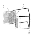
- FIG. 16 is a photograph of a prototype of a reclinable chair exemplifying the principles of the present invention.
- FIG. 17 is a partial top perspective view of a flexible support surface attached to a support frame of a chair embodying the principles of the present invention.
- FIG. 18 is a side perspective view of another reclinable chair exemplifying the principles of the present invention.
- FIG. 19 is a side perspective view of a cushion for use with a reclinable chair exemplifying the principles of the present invention.
- FIG. 20 a is a side perspective view of yet another embodiment of a reclinable chair exemplifying the principles of the present invention.
- FIG. 20 b is a side perspective view of the chair of FIG. 20 a with the cushion of FIG. 19 ;
- FIG. 21 is a front perspective view of a family of reclinable chairs exemplifying the principles of the present invention.
- Relational terms such as first and second, top and bottom, and the like may be used solely to distinguish one entity or action from another entity or action without necessarily requiring or implying any actual such relationship or order between such entities or actions.
- the terms “comprises,” “comprising,” or any other variation thereof are intended to cover a non-exclusive inclusion, such that a process, method, article, or apparatus that comprises a list of elements does not include only those elements but may include other elements not expressly listed or inherent to such process, method, article, or apparatus.
- An element proceeded by “comprises . . . a” does not, without more constraints, preclude the existence of additional identical elements in the process, method, article, or apparatus that comprises the element.
- the term “about” or “approximately” applies to all numeric values, whether or not explicitly indicated. These terms generally refer to a range of numbers that one of skill in the art would consider equivalent to the recited values (i.e., having the same function or result). In many instances these terms may include numbers that are rounded to the nearest significant figure.
- the present invention is a chair, which provides improved comfort and support while maintaining simplicity in its design.
- a stackable chair embodiment of the invention is particularly useful when the chairs are for temporary use.
- a chair 10 embodying the principles of the invention includes a flexible support surface 30 supported by a support frame 40 on a chair base 20 .
- the chair 10 is a stacking chair with a sled base 20 in the form of cylindrical tubing, preferably constructed out of metallic or semi-metallic material such as steel and aluminum.
- the support frame 40 includes three or more component frames, at least two of which secure the support frame 40 to the base 20 . As depicted in FIG.
- an exemplary support frame 40 includes a front frame portion 42 pivotally attached to the front end 22 of the base 20 ; a back frame portion 44 pivotally attached to the rear end 24 of the base 20 ; and a seat frame portion 46 disposed between and pivotally connected to both the front and back frame portions 42 , 44 .
- the component frames 42 , 44 , 46 and the base 20 cooperatively function as a linkage system to provide a weight-sensitive recline mechanism and a low-profile, high-stacking chair 10 .
- FIG. 4 depicts a plurality of stacked chairs 10 , wherein, due to the small footprint of the recline mechanism, there is very little distance between adjacent chairs 10 . Thus, the chairs 10 can be stacked high during storage.
- the recline mechanism includes a linkage system having four pivot axes A, B, C, and D about which the support frame 40 pivots to move the chair 10 between an upright position ( FIGS. 7 a , 8 a , 9 a ) and a reclined position ( FIGS. 7 b , 8 b , 9 b ).
- the back frame portion 44 is pivotally secured to the base rear end 24 about a first pivot axis A.
- the back frame portion 44 is a contoured frame including a top edge 43 having a concave shape when viewed from the top ( FIGS.
- the side edges 45 When viewed from the side ( FIGS. 7 a and 7 b ), the side edges 45 have a soft S-shaped curve (S) (see FIG. 6 a ) extending between about the middle section of the side edge 45 and the lower ends of the side edges 45 . As shown in FIGS. 6 a and 6 b , the side edges 45 include opposing apertures 48 at about the middle section of the (S) curve, at approximately the start of the bottom curve of the (S) curve.
- S soft S-shaped curve
- the opposing apertures 48 are shaped to receive and rotate about opposing ends 25 of the base rear end 24 , the pivot axis A thus extending through the opposing apertures 48 .
- the opposing ends 25 of the base 20 are securely retained within the apertures 48 by any suitable means known in the art.
- the back frame portion 44 includes a slightly concave curved support bar 49 extending between the opposing apertures 48 to provide additional support for the occupant.
- an exemplary front frame portion 42 of the support frame 40 is pivotally secured to the base front end 22 about a second pivot axis D.
- an exemplary front frame portion 42 includes a horizontal bottom edge 50 defining an aperture 52 shaped to receive and rotate about a horizontal cross-bar 26 at the front end 22 of the base 20 , the pivot axis D thus extending through the aperture 52 and the horizontal cross-bar 26 .
- the front frame portion 42 can be pivotally secured to the base front end 22 by any suitable means known or contemplated by one of ordinary skill in the art.
- the base 20 can be assembled in separate pieces, the horizontal cross-bar 26 being received within a predefined aperture 52 of the front frame portion 42 prior to being assembled to the remaining base portions.
- two opposing sections of the front frame portion 42 can be attached together about the horizontal crossbar 26 of a preassembled base 20 to form the aperture 52 , for example, through welding or any other suitable attachment means known in the art.
- the front frame portion 42 has two opposing side edges 54 that curve upward and away from the bottom edge 50 .
- the front frame portion 42 is connected to the back frame portion 44 by at least one connecting frame portion about at least two additional pivot axes.
- the support frame 40 includes a seat frame portion 46 disposed between the front and back frame portions 42 , 44 .
- an exemplary seat frame portion 46 includes two side edges 62 and two slightly concave curved support bars 64 extending therebetween to provide additional support to the flexible support surface 30 and the occupant.
- the seat frame portion 46 is connected to the back frame portion 44 through a first pair of opposing hinges 56 , thus defining a third pivot axis B, and to the front frame portion 42 through a second pair of opposing hinges 56 , thus defining a fourth pivot axis C.
- the opposing side edges 45 of the back frame portion 44 include first hinge sub-parts 56 a at the lower ends of the (S) curve configured to mate with the corresponding second hinge sub-parts 56 b at the rear end of the side edges 62 of seat frame portion 46 .
- first hinge sub-parts 56 a configured to mate with the corresponding second hinge sub-parts 56 b at the front end of the side edges 62 of the seat frame portion 46 . It is also within the scope of the present invention for the first hinge sub-parts 56 a on the front and back frame portions 42 , 44 to be second hinge sub-parts 56 b and for the second hinge sub-parts 56 b on the seat frame portion 46 to be first hinge sub-parts 56 a.
- FIG. 10 shows a bottom perspective view of a rear hinge 56 joining the rear end of the seat frame portion 46 and the back frame portion 44 , shown in the biased upright position, wherein a space exists between lower stop surfaces 57 a , 57 b of respective hinge sub-parts 56 a , 56 b .
- the occupant may use his or her weight to push against the back frame portion 44 to recline the chair 10 into the reclined position.
- the back frame portion 44 pivots about axis A, wherein the top portion of the back frame portion 44 pivots in the direction of arrow R 1 ( FIG. 7 b ) and the bottom portion of back frame portion 44 pivots in the direction of arrow R 2 ( FIGS.
- the front hinges 56 connecting the front end of the seat frame portion 46 and the front frame portion 42 are configured such that recline movement transferred through the seat frame portion 46 causes the front hinges 56 to pivot about axis C, pivoting the front frame portion 42 forward about axis D in the direction of arrow R 4 ( FIG. 7 b ).
- the base 20 includes a crossbar 28 extending along the front and sides thereof to prevent the base 20 from moving as the chair 10 reclines.
- the crossbar 28 can be a one-piece crossbar 28 , integrally formed with two bends, extending from a first side of the rear end 24 to a first side of the front end 22 , across to a second side of the front end 22 , and back toward a second side of the rear end 24 .
- the base 20 can include three individual and separately attached crossbars 28 .
- the crossbar 28 can be attached to the base 20 by any suitable means in the art that would maintain the base 20 in a static position as the occupant reclines in the chair 10 .
- an exemplary flexible support surface 30 includes a backrest portion 72 and a seat portion 74 , each formed with a pattern of holes or openings, and a solid border 76 (no openings formed therethrough) surrounding each of the backrest and seat portions 72 , 74 .
- the backrest and seat portions 72 , 74 are thus separated by the solid border 76 .
- the backrest and seat portions 72 , 74 may be integrally formed as a one-piece flexible support surface 30 ( FIG. 2 ) or they may be comprised of separate pieces attached to each other and/or the support frame 40 ( FIG. 16 ).
- an exemplary flexible support surface 30 embodying the principles of the present invention includes a pattern of holes formed through the flexible support surface 30 in such a way that the areas having greater flexibility actually have smaller openings and more surrounding material and the areas having less flexibility have larger openings and less surrounding material.
- FIGS. 12 a to 12 c and FIG. 13 include diagrams outlining the thought-process behind the development of an exemplary flexible support surface pattern 30 .
- An ideal way to transmit force throughout the flexible support surface 30 is to keep the same number of connectors throughout the pattern. Building upon the analogy force distribution equals frequency, it was thought to alter the two variables of the pattern design (pitch and stop) and create something that looks like a derivative of a frequency monitor ( FIG. 12 a ), i.e., a softer version of a frequency line ( FIG. 12 b ). Nature always responds to changes with variable frequencies—an exemplary pattern would replicate that. Following this logic, referring to FIG.
- a pattern of shapes defined by straighter lines equates to less material, whereas a pattern of shapes defined by higher pitch curvature lines equates to more material.
- a flexible support surface having a pattern of openings shaped by a plurality of segments similar to the curvilinear segment ( 3 ) of FIG. 13 would be comprised of more material than a pattern of openings shaped by the same number of segments, but similar to the straight segment ( 1 ) of FIG. 13 .
- the present invention utilizes a pattern of openings shaped by a plurality of higher pitch curvilinear segments (and thus more material) to provide greater flexibility and a pattern of openings shaped by a plurality of lower pitch, straighter segments (and thus less material) to provide less flexibility.
- FIG. 14 illustrates two exemplary alternative shapes that may be used to define a pattern of openings, of course with varying pitch and step, i.e., the segments defining the shape are straighter in areas of less flexibility and curvier in areas of greater flexibility.
- FIGS. 15 a to 15 d illustrate different pattern variations that were tested for flexibility.
- the pattern P 1 of FIG. 15 a is defined by a plurality of openings shaped by lines or segments 68 a ;
- the pattern P 2 of FIG. 15 b is defined by a plurality of openings shaped by lines or segments 68 b ;
- the pattern P 3 of FIG. 15 c is defined by a plurality of openings shaped by lines or segments 68 c ;
- the pattern P 4 of FIG. 15 d is defined by a plurality of openings shaped by lines or segments 68 d .
- Segments 68 a are substantially straight; segments 68 b have a higher pitch curvature than segments 68 a ; segments 68 c have a higher pitch curvature than segments 68 b ; and segments 68 d have the highest pitch curvature of all segments 68 a , 68 b , 68 c , 68 d . Flexibility tests performed on each of the four patterns P 1 to P 4 revealed that flexibility increased as the pitch curvature of the segments defining the opening shape increased, pattern P 1 thus having the least amount of flexibility and pattern P 4 having the greatest flexibility of the four tested patterns. Accordingly, an exemplary flexible surface support 30 includes variations of the patterns P 1 to P 4 as desired flexibility dictates.
- FIG. 16 illustrates an exemplary flexible support surface 30 having variations in patterns P 2 to P 4 .
- the flexible support surface 30 includes a less flexible pattern P 2 at the top of the backrest portion 72 and transitions to a more flexible pattern toward the middle of the backrest portion 72 , first pattern P 3 and then pattern P 4 .
- the pattern transitions back to the pattern P 3 and then the less flexible pattern P 2 at the bottom of the backrest portion 72 .
- the flexible support surface 30 includes a more flexible pattern P 3 at the rear and front of the seat portion 74 and an even more flexible pattern P 4 around the middle of the seat portion 74 .
- the pattern variation depicted in FIG. 16 is merely exemplary.
- the patterns may vary from side to side across the backrest and seat portions 72 , 74 .
- An exemplary flexible support surface 30 may be formed from any suitable flexible material known or contemplated in the art including but not limited to elastomeric materials such as Hytrel®, manufactured by DuPont.
- the flexible support surface 30 can be formed from any suitable method known in the art, including but not limited to common molding methods such as injection molding.
- FIG. 17 An exemplary method of attaching a flexible support surface 30 to the support frame 40 is illustrated in FIG. 17 .
- the support frame 40 has a series of slots or recesses 41 formed in the outer edge surfaces, the recesses 41 being operable to receive the flexible support surface 30 therein.
- the flexible support surface 30 is shaped along its edges to form a geometric fit within the recesses 41 of the support frame 40 . As shown in FIG. 17 , some of the recesses 41 are shaped to receive a screw 47 or the like therethrough to further secure the flexible support surface 30 to the support frame 40 .
- FIG. 18 illustrates another chair 110 embodying the principles of the present invention, wherein parts common with the chair 10 are denoted by like reference numerals increased by 100.
- the flexible support surface 130 does not include a pattern of holes formed therethrough.
- FIG. 19 illustrates a cushion 80 attachable to any of the chair embodiments disclosed herein through any suitable means known in the art (e.g., snap closures, adhesives, ties, and the like) to provide added comfort to the occupant.
- the cushion 80 can be comprised of any suitable material used in chair cushions, e.g., foam, Technogel®, and the like.
- FIG. 20 a illustrates a task chair 210 embodying the principles of the present invention, wherein parts common with the chair 10 are denoted by like reference numerals increased by 200 .
- the task chair 210 includes a flexible support surface 230 supported by a support frame 240 on a height adjustable swivel base 221 having a plurality of casters 282 .
- FIG. 20 b shows the chair 210 with a cushion 80 attached to the flexible support surface 230 .
- FIG. 21 A family of exemplary chairs embodying the principles of the present invention is illustrated in FIG. 21 .
- the common features between all chairs (a) to (g) within the exemplary family of chairs include the inventive recline mechanism, comprised of a support frame 40 that functions as a four-pivot linkage system, and the flexible support surface supported on the support frame.
- Chair (c) is the chair 10 illustrated above and chairs (a) and (b) are variations thereof: chair (b) including a pair of armrests extending from the base, and chair (a) including an armrest and an opposing desktop extending from the base.
- Chairs (d) to (g) include variations of the base: chairs (d) and (e) being the task chairs 210 of FIGS.
- chair (f) including a loop frame base, which also functions as a pair of armrests
- chair (g) including what is commonly referred to in the art as a cantilever base, which also functions as a pair of armrests.
Abstract
Description
Claims (16)
Priority Applications (1)
| Application Number | Priority Date | Filing Date | Title |
|---|---|---|---|
| US13/860,421 US9504326B1 (en) | 2012-04-10 | 2013-04-10 | Reclining chair |
Applications Claiming Priority (3)
| Application Number | Priority Date | Filing Date | Title |
|---|---|---|---|
| US201261622358P | 2012-04-10 | 2012-04-10 | |
| US201261625373P | 2012-04-17 | 2012-04-17 | |
| US13/860,421 US9504326B1 (en) | 2012-04-10 | 2013-04-10 | Reclining chair |
Publications (1)
| Publication Number | Publication Date |
|---|---|
| US9504326B1 true US9504326B1 (en) | 2016-11-29 |
Family
ID=57351862
Family Applications (1)
| Application Number | Title | Priority Date | Filing Date |
|---|---|---|---|
| US13/860,421 Active 2033-07-08 US9504326B1 (en) | 2012-04-10 | 2013-04-10 | Reclining chair |
Country Status (1)
| Country | Link |
|---|---|
| US (1) | US9504326B1 (en) |
Cited By (14)
| Publication number | Priority date | Publication date | Assignee | Title |
|---|---|---|---|---|
| USD831992S1 (en) * | 2016-03-09 | 2018-10-30 | B 4 Living Spa | Chair |
| USD846932S1 (en) * | 2017-11-22 | 2019-04-30 | Office Depot, Inc. | Chair |
| USD869183S1 (en) * | 2018-10-27 | 2019-12-10 | Emu Group S.P.A. | Chair with armrests |
| US10820705B2 (en) | 2016-09-29 | 2020-11-03 | Steelcase Inc. | Compliant seating structure |
| US11140989B2 (en) * | 2016-09-23 | 2021-10-12 | Aichi Co., Ltd. | Chair and structure body thereof |
| US11324323B2 (en) | 2019-09-18 | 2022-05-10 | Steelcase Inc. | Body support member with lattice structure |
| USD961953S1 (en) * | 2021-05-24 | 2022-08-30 | Menu A/S | Dining chair |
| US20220295996A1 (en) * | 2021-03-18 | 2022-09-22 | Pro-Cord S.P.A. | Chair with pivoting seat and backrest |
| US11510502B2 (en) * | 2015-06-29 | 2022-11-29 | MillerKnoll, Inc. | Attachment structure for suspension seating |
| US11510495B1 (en) | 2021-05-14 | 2022-11-29 | Steelcase Inc. | Chair having an accessory hook |
| USD999549S1 (en) * | 2020-12-08 | 2023-09-26 | Aichi Co., Ltd. | Chair |
| US11812870B2 (en) | 2021-02-10 | 2023-11-14 | Steelcase Inc. | Body support structure |
| USD1009536S1 (en) | 2021-05-17 | 2024-01-02 | Steelcase Inc. | Chair |
| US11864658B2 (en) * | 2016-02-05 | 2024-01-09 | Formway Furniture Limited | Chair and components |
Citations (267)
| Publication number | Priority date | Publication date | Assignee | Title |
|---|---|---|---|---|
| US242733A (en) * | 1881-06-07 | Reclining-chair | ||
| US2126439A (en) | 1937-07-06 | 1938-08-09 | Louis J Zerbee | Spring assembly |
| US2324902A (en) | 1940-03-28 | 1943-07-20 | Nash Kelvinator Corp | Seat construction |
| GB577369A (en) | 1944-05-22 | 1946-05-15 | H C Shepherd & Company Ltd | Improvements in and relating to stackable chairs |
| US2456797A (en) | 1945-05-25 | 1948-12-21 | Collier Keyworth Company | Chair iron for tiltable seats and backs |
| US2473895A (en) | 1947-09-02 | 1949-06-21 | Mednick Philip | Chair |
| US2497395A (en) | 1946-03-04 | 1950-02-14 | Sr Roy A Cramer | Reclining chair |
| US2638149A (en) | 1949-11-26 | 1953-05-12 | Cleveland Welding Co | Tubular metal chair frame |
| US2778408A (en) | 1954-08-09 | 1957-01-22 | Albert P Krikorian | Reclining chair |
| US2838095A (en) | 1955-12-07 | 1958-06-10 | Charles U Deaton | Posture chairs |
| US2859801A (en) | 1956-09-17 | 1958-11-11 | Edwin R Moore | Geometric controller for chairs |
| US2859799A (en) | 1956-05-03 | 1958-11-11 | Edwin R Moore | Functional posture controller for chairs |
| US2991125A (en) | 1957-03-21 | 1961-07-04 | Lie Finn | Tilting chair construction |
| US3041109A (en) | 1958-09-29 | 1962-06-26 | Miller Herman Inc | Web and spreader furniture construction |
| US3205010A (en) | 1964-05-19 | 1965-09-07 | William F Schick | Seat cushion |
| US3333811A (en) | 1965-09-07 | 1967-08-01 | Wil Mat Corp | Rocker mechanism |
| US3337267A (en) | 1966-01-27 | 1967-08-22 | Royal Dev Co | Positionable chair |
| US3399906A (en) | 1966-02-04 | 1968-09-03 | Ring Sidney B | Occupant-propelled skate board vehicle |
| US3446532A (en) * | 1967-03-13 | 1969-05-27 | Harold W Cramer | Chair |
| US3450435A (en) | 1967-03-31 | 1969-06-17 | Art Metal Knoll Corp | Furniture construction |
| US3489458A (en) | 1968-06-21 | 1970-01-13 | Hardman Aerospace | Armrest assembly |
| US3540776A (en) | 1968-11-29 | 1970-11-17 | Wilson Seat Co | Seat cushion |
| US3572829A (en) | 1968-07-18 | 1971-03-30 | Companie Nationale Air France | Tiltable air plane seat |
| US3630572A (en) | 1969-09-23 | 1971-12-28 | Lear Siegler Inc | Seat assembly |
| GB1291263A (en) | 1969-09-11 | 1972-10-04 | Vitafoam Ltd | Improvements in or relating to seating suspension |
| US3709557A (en) | 1970-08-12 | 1973-01-09 | Flat Back Corp | Portable vertebral column support |
| US3712666A (en) * | 1969-12-17 | 1973-01-23 | Giroflex Entwicklungs Ag | Chair |
| US3774967A (en) | 1971-03-22 | 1973-11-27 | D Rowland | Seating and sub-assembly for seats and backs |
| US3815955A (en) | 1972-12-29 | 1974-06-11 | Vecta Group | Chair construction |
| US3904242A (en) | 1973-12-28 | 1975-09-09 | Harter Corp | Chair construction and method for producing same |
| US3916461A (en) | 1973-02-14 | 1975-11-04 | Gerdikerstholt Geb Spath | Article of furniture with a multi-section support surface |
| US3924893A (en) | 1974-10-17 | 1975-12-09 | Gen Motors Corp | Ventilated vehicle seat |
| US3939565A (en) | 1969-06-11 | 1976-02-24 | Bush Roberta F | Pattern fitting tool and method of custom fitting patters |
| GB1428185A (en) | 1972-08-22 | 1976-03-17 | Alphonse J | Decorative panels |
| US3947069A (en) | 1973-01-24 | 1976-03-30 | Ferdinand Lusch | Adjustable deck-chair |
| USD246813S (en) | 1976-08-02 | 1978-01-03 | Krueger Metal Products, Inc. | Chair |
| US4068888A (en) | 1976-01-07 | 1978-01-17 | Homecrest Industries, Inc. | Recliner chair |
| US4084850A (en) | 1975-06-13 | 1978-04-18 | Center For Design Research And Development N.V. | Chair |
| US4234226A (en) | 1978-10-02 | 1980-11-18 | Scott Paper Company | Adjustable and collapsible seating piece |
| US4270798A (en) | 1979-07-10 | 1981-06-02 | Coach & Car Equipment Corporation | Breakaway arm for seat |
| US4362336A (en) | 1979-04-07 | 1982-12-07 | Otto Zapf | Sliding chair |
| US4379589A (en) | 1980-09-03 | 1983-04-12 | Interieur Forma S.A. | Reclinable chair |
| US4408800A (en) | 1980-06-11 | 1983-10-11 | American Seating Company | Office chairs |
| US4411469A (en) | 1979-07-23 | 1983-10-25 | Drabert Sohne | Chair, particularly a data display chair |
| US4429917A (en) | 1981-04-29 | 1984-02-07 | Hauserman Inc. Int. Furniture & Textile Division | Chair |
| US4451085A (en) | 1980-10-01 | 1984-05-29 | Wilkhahn & Hahne GmbH & Company | Chair |
| US4452486A (en) | 1980-09-24 | 1984-06-05 | Otto Zapf | Chair type furniture |
| USD274675S (en) | 1981-04-29 | 1984-07-17 | Hauserman Inc., Int. Furniture & Tex Div. | Chair |
| US4478454A (en) | 1981-06-08 | 1984-10-23 | Steelcase Inc. | Weight-actuated chair control |
| US4479679A (en) | 1981-06-08 | 1984-10-30 | Steelcase Inc. | Body weight chair control |
| US4502729A (en) | 1981-08-19 | 1985-03-05 | Giroflex Entwicklungs Ag | Chair, especially a reclining chair |
| US4522444A (en) | 1982-09-15 | 1985-06-11 | Charles Pollock | Stacking chair |
| US4555139A (en) | 1982-04-15 | 1985-11-26 | Leib Roger K | Patient's defined-motion chair |
| US4583778A (en) | 1985-02-05 | 1986-04-22 | Liebhold Martin R | Folding knock-down chair, with swingable seat support |
| US4603907A (en) | 1983-11-30 | 1986-08-05 | Hoover Universal, Inc. | J-clip mounting system for load bearing seat members |
| US4609225A (en) | 1985-01-17 | 1986-09-02 | Loucks Harry D | Folding chair with membrane shell |
| US4618185A (en) | 1984-09-19 | 1986-10-21 | Yaacov Kaufman | Ergonomic chair |
| JPS61247418A (en) | 1984-08-08 | 1986-11-04 | シルケル ビ−ブイ | Chair |
| US4639042A (en) | 1985-05-21 | 1987-01-27 | Fixtures Manufacturing Corporation | Chair back arrangement |
| US4640548A (en) | 1981-10-03 | 1987-02-03 | Kusch & Co. Stizmobelwerke Kg | Chair with an adjustable backrest |
| US4685730A (en) * | 1984-12-21 | 1987-08-11 | Etablissements Linguanotto | Seat, especially work seat, with several positions |
| US4709962A (en) | 1984-10-24 | 1987-12-01 | Kloeber Gmbh & Co. | Work chair with a tilting mechanism for seat squab and backrest |
| US4709963A (en) | 1986-12-12 | 1987-12-01 | Milsco Manufacturing Company | Adjustable office chair |
| US4733910A (en) | 1985-03-18 | 1988-03-29 | Sebel Furniture Ltd. | Article of furniture |
| US4744603A (en) | 1986-04-10 | 1988-05-17 | Steelcase Inc. | Chair shell with selective back stiffening |
| US4761033A (en) | 1986-05-26 | 1988-08-02 | Drabert Sohne Gmbh & Co. | Chair |
| US4765679A (en) | 1986-05-26 | 1988-08-23 | Drabert Sohne Gmbh & Co. | Chair having a seat with front and rear seat portions being hinged to each other |
| US4773706A (en) | 1986-07-03 | 1988-09-27 | Dr. Ing. H.C.F. Porsche Aktiengesellschaft | Chair, particularly an office chair |
| US4796952A (en) | 1986-06-12 | 1989-01-10 | Giancarlo Piretti | Chair with hinged backrest |
| US4830430A (en) | 1987-01-30 | 1989-05-16 | Equus Marketing Ag | Split-back chair, particularly office chair |
| US4842333A (en) | 1987-08-14 | 1989-06-27 | Grammer Sitzsysteme Gmbh | Seat |
| US4856846A (en) | 1986-02-13 | 1989-08-15 | Hartmut Lohmeyer | Chair with a seat and an inherently elastically pliable back rest |
| US4877291A (en) | 1987-12-14 | 1989-10-31 | Taylor William P | Reclining chair |
| US4883320A (en) | 1987-07-15 | 1989-11-28 | Ikeda Bussan Co., Ltd. | Seat structure |
| US4889385A (en) | 1988-03-09 | 1989-12-26 | American Seating Company | Chair seat-and-back support |
| US4892355A (en) | 1986-03-21 | 1990-01-09 | Samsonite Furniture Company | Chair construction |
| USD308143S (en) | 1985-09-16 | 1990-05-29 | Krueger International, Inc. | Chair |
| US4938530A (en) | 1988-01-27 | 1990-07-03 | Steelcase, Inc. | Wire frame chair |
| US4943114A (en) | 1989-02-06 | 1990-07-24 | Giancarlo Piretti | Chair backrest linkage mechanism |
| US4966411A (en) | 1987-10-24 | 1990-10-30 | Kokuyo Co., Ltd. | Chair provided with a backrest |
| US4988145A (en) * | 1986-06-04 | 1991-01-29 | Roeder Gmbh Sitzmoebelwerke | Seating furniture |
| US4997234A (en) | 1989-05-11 | 1991-03-05 | Stinchfield Enterprises, Inc. | Rocker-recliner chair |
| US5009466A (en) * | 1988-04-25 | 1991-04-23 | Perry Charles O | Reclining chair |
| US5013089A (en) | 1989-09-15 | 1991-05-07 | General Motors Corporation | Thin profile integrated suspension and seat trim cover |
| US5015031A (en) | 1989-04-20 | 1991-05-14 | Ferdinand Lusch Gmbh & Co. Kg. | Reclining chair |
| US5018791A (en) | 1988-03-08 | 1991-05-28 | Otto Zapf | Seating furniture |
| US5035466A (en) | 1989-04-03 | 1991-07-30 | Krueger International, Inc. | Ergonomic chair |
| US5076646A (en) | 1989-12-06 | 1991-12-31 | Denis Matte | One-piece shell for a chair |
| US5080318A (en) | 1989-11-30 | 1992-01-14 | Itoki Kosakusho Co., Ltd. | Tilting control assembly for chair |
| DE4023607A1 (en) | 1990-07-25 | 1992-01-30 | Koolwijk Jan | Tilt mechanism for office swivel chair - provides synchronous movement of seat and backrest in angle ratio of 1 to 2 |
| DE4033972A1 (en) | 1990-10-25 | 1992-04-30 | Buerositzmoebelfabrik Friedric | Free swinging chair on frame - has pivot mounted back rest, with pivot axle and seat, with slide guide containing bolt in slide bearing |
| US5123702A (en) | 1990-10-24 | 1992-06-23 | Shelby Williams Industries, Inc. | Interaction-high density stacking chair |
| US5150948A (en) | 1989-09-16 | 1992-09-29 | Voelkle Rolf | Reclining chair |
| WO1993003653A1 (en) | 1991-08-22 | 1993-03-04 | Peter James Riddle | Weight compensating chair backrest |
| US5195801A (en) | 1989-01-05 | 1993-03-23 | Wilkhahn Wilkening & Hahne Gmbh & Co. | Tiltable chair |
| USD339940S (en) | 1991-11-25 | 1993-10-05 | Krueger International, Inc. | Chair seat |
| US5251958A (en) | 1989-12-29 | 1993-10-12 | Wilkhahn Wilkening & Hahne Gmbh & Co. | Synchronous adjusting device for office chairs or the like |
| US5261723A (en) | 1987-12-28 | 1993-11-16 | Isao Hosoe | Ergonomic chair having the seat at a varying position |
| US5267777A (en) | 1992-01-15 | 1993-12-07 | Lavaco Industries, Inc. | Resilient chair support |
| US5288138A (en) | 1990-08-10 | 1994-02-22 | Stulik Edward L | Reclining chair |
| US5292177A (en) | 1991-11-25 | 1994-03-08 | Krueger International, Inc. | Modular seating system |
| US5292097A (en) | 1989-10-31 | 1994-03-08 | Russell Edwin R | Work surface support |
| US5308144A (en) | 1989-05-20 | 1994-05-03 | Roeder Gmbh | Chair, in particular work or office chair |
| US5314240A (en) | 1991-05-21 | 1994-05-24 | Itoki Co., Ltd. | Shell structure for use with a chair having synchronously moving seat and seat back |
| US5314237A (en) | 1992-02-12 | 1994-05-24 | Kimball International Marketing, Inc. | Reclining chair |
| US5338094A (en) | 1988-04-25 | 1994-08-16 | Perry Charles O | Flexible reclining chair |
| US5354120A (en) | 1991-10-31 | 1994-10-11 | Voelkle Rolf | Reclining chair |
| US5383712A (en) | 1988-04-25 | 1995-01-24 | Perry; Charles O. | Flexible chair |
| US5393120A (en) | 1992-10-13 | 1995-02-28 | Krueger International, Inc. | Auditorium seating system |
| US5393126A (en) | 1993-06-21 | 1995-02-28 | Art Design International Inc. | Tubular frame seating structure with tension sleeve |
| US5401077A (en) | 1991-02-20 | 1995-03-28 | Hosoe; Isao | Ergonomically improved chair or armchair |
| US5486035A (en) | 1994-08-01 | 1996-01-23 | Koepke; Marcus C. | Occupant weight operated chair |
| US5503455A (en) | 1994-05-31 | 1996-04-02 | Formosa Saint Jose Corp. | Back cushion with optionally adjustable inclination |
| US5524966A (en) | 1993-05-27 | 1996-06-11 | Pro-Cord S.R.L. | Folding chair with tilting backrest |
| US5549358A (en) | 1993-10-26 | 1996-08-27 | Eisen- Und Drahtwerk Erlau Aktiengesellschaft | Seat |
| US5577807A (en) | 1994-06-09 | 1996-11-26 | Steelcase Inc. | Adjustable chair actuator |
| US5580127A (en) | 1993-05-27 | 1996-12-03 | Pro-Cord S.R.L. | Chair with tilting backrest |
| US5582459A (en) | 1993-09-30 | 1996-12-10 | Itoki Crebio Corporation | Chair having tiltable seat back |
| US5603551A (en) | 1996-01-16 | 1997-02-18 | Sheehan; Kelly | Gravitational resistant positional chair |
| DE29707354U1 (en) | 1996-04-30 | 1997-06-19 | Zueco Buerositzmoebel Ag | chair |
| US5660439A (en) | 1995-01-04 | 1997-08-26 | Unwalla; Jamshed | Integrated seat and back and mechanisms for chairs |
| US5662381A (en) | 1991-05-30 | 1997-09-02 | Steelcase Inc. | Chair construction and method of assembly |
| US5683142A (en) | 1996-06-20 | 1997-11-04 | Krueger International, Inc. | Mounting assembly for chair back |
| US5686035A (en) | 1994-08-15 | 1997-11-11 | Matrex Furniture Components, Inc. | Method for forming a cushion |
| USD390024S (en) | 1996-10-31 | 1998-02-03 | Krueger International, Inc. | Stack chair |
| US5716101A (en) | 1996-07-12 | 1998-02-10 | Bjip, Inc. | Seat rail attachment device |
| US5716099A (en) * | 1996-08-14 | 1998-02-10 | Novimex Fashion Ltd. | Chair with split reclining seat |
| US5725276A (en) | 1995-06-07 | 1998-03-10 | Ginat; Jonathan | Tilt back chair and control |
| US5725277A (en) | 1986-04-10 | 1998-03-10 | Steelcase Inc. | Synchrotilt chair |
| US5747140A (en) | 1995-03-25 | 1998-05-05 | Heerklotz; Siegfried | Flat upholstered body |
| US5755488A (en) | 1997-03-06 | 1998-05-26 | Steelcase Inc. | Chair with adjustable seat |
| US5772282A (en) | 1992-06-15 | 1998-06-30 | Herman Miller Inc. | Tilt control mechanism for a chair |
| US5775774A (en) | 1996-08-12 | 1998-07-07 | Okano; Hiroshi | Tilt mechanism for chairs |
| US5785384A (en) | 1994-10-14 | 1998-07-28 | Handicare Industri A/S | Arrangement in an adjustable chair |
| US5823626A (en) | 1996-12-30 | 1998-10-20 | Haas; Peter J. | Mechanism for reclining chairs |
| US5826940A (en) | 1995-11-27 | 1998-10-27 | Hodgdon; Dewey | Reactive multi-position chair |
| US5842739A (en) | 1995-11-30 | 1998-12-01 | Forever Children | Adjustable baby head and body support |
| US5845970A (en) | 1996-08-26 | 1998-12-08 | Sun Isle Casual Furniture, Llc | Yarn having wicker appearance and article made therefrom |
| US5862874A (en) | 1997-06-19 | 1999-01-26 | University Of Pittsburgh | Steering mechanism for short wheelbased four-wheeled vehicles |
| US5899531A (en) | 1996-08-20 | 1999-05-04 | Krueger International, Inc. | Stationarily-mounted seating structure |
| US5902012A (en) | 1997-04-03 | 1999-05-11 | Han; Moogil | Chair with movable back |
| US5904397A (en) * | 1995-05-02 | 1999-05-18 | Hag A/S | Seating unit comprising two adjacent, pivotal support elements |
| USD410808S (en) | 1997-03-06 | 1999-06-08 | Krueger International, Inc. | Chair |
| US5924770A (en) | 1998-05-15 | 1999-07-20 | Virco Mfg. Corporation | Chair construction |
| US5931531A (en) | 1997-01-23 | 1999-08-03 | Comforto Gmbh | Chair having adjustable synchronous tilting |
| USD412622S (en) | 1997-03-20 | 1999-08-10 | Krueger International, Inc. | Seating system |
| US5944382A (en) | 1996-10-09 | 1999-08-31 | Center For Design Research And Development N.V. | Adjustable seating |
| US5964473A (en) | 1994-11-18 | 1999-10-12 | Degonda-Rehab S.A. | Wheelchair for transporting or assisting the displacement of at least one user, particularly for handicapped person |
| USRE36335E (en) | 1988-04-25 | 1999-10-12 | Perry; Charles O. | Flexible chair |
| US5964503A (en) | 1997-04-28 | 1999-10-12 | Inoue Associates, Inc. | Chair |
| USD415912S (en) | 1998-12-11 | 1999-11-02 | Krueger International, Inc. | Chair seat |
| USD416407S (en) | 1998-12-11 | 1999-11-16 | Krueger International, Inc. | Chair |
| US5988757A (en) | 1996-08-29 | 1999-11-23 | Lear Corporation | Vehicle seat assembly |
| US6000755A (en) | 1997-06-20 | 1999-12-14 | Uhlenbrock; Johannes | Swivel chair |
| USD417570S (en) | 1998-12-11 | 1999-12-14 | Krueger International, Inc. | Chair back |
| US6003948A (en) | 1998-05-15 | 1999-12-21 | Virco Mfg. Corporation | Chair construction |
| US6012774A (en) | 1996-11-18 | 2000-01-11 | Hwe, Inc. | Reclining chair with guide rail system |
| USD420540S (en) | 1998-12-11 | 2000-02-15 | Krueger International, Inc. | Chair back |
| US6050646A (en) | 1997-12-10 | 2000-04-18 | Sedus Stoll Ag | Backrest |
| US6086153A (en) | 1997-10-24 | 2000-07-11 | Steelcase Inc. | Chair with reclineable back and adjustable energy mechanism |
| US6102482A (en) | 1999-05-07 | 2000-08-15 | Collins & Aikman Products Co. | Lightweight suspension panel for vehicle seats and door panels |
| US6109694A (en) | 1999-06-01 | 2000-08-29 | Hon Technololgy, Inc. | Chair with four-bar linkage for self-adjusting back tension |
| US6113186A (en) | 1999-05-21 | 2000-09-05 | Chromcraft/Revington Company | Multiple seat assembly I |
| WO2000074531A2 (en) | 1999-06-04 | 2000-12-14 | Soft/View Computer Products Corp. | Ergonomic chair |
| USD435746S1 (en) | 1999-04-09 | 2001-01-02 | Softview Computer Products Corp. | Chair arm |
| US6168233B1 (en) | 2000-03-15 | 2001-01-02 | Isidoro Natalio Markus | Reclinable seating using a torsion bar |
| US6217114B1 (en) | 1995-12-21 | 2001-04-17 | Degonda-Rehab Sa | Stationary or wheeled inclinable seat arrangement, in particular for the sick or handicapped |
| US6234578B1 (en) | 1998-05-12 | 2001-05-22 | Mccord Winn Textron, Inc. | Seating assembly and method of making same |
| US6234573B1 (en) | 1998-05-27 | 2001-05-22 | Peter Röder | Chair, in particular office chair |
| US6238000B1 (en) | 1998-02-04 | 2001-05-29 | Unit Press Limited | Mechanism for chair |
| US6247753B1 (en) | 1997-02-28 | 2001-06-19 | Kjartan Alvestad | Arrangement for beds and other reclining or seating furniture |
| US6296312B1 (en) | 1995-02-21 | 2001-10-02 | Neutral Posture Ergonomics, Inc. | Armrest assembly |
| US20010030457A1 (en) | 1999-09-29 | 2001-10-18 | Gregory Peter G. G. | Chair |
| US6311939B1 (en) | 1995-08-31 | 2001-11-06 | Leslie Palmatier Christensen | Integrated mouse pad and wrist and arm support |
| WO2001093907A1 (en) | 2000-06-07 | 2001-12-13 | Center For Design Research And Development N.V. | Chair |
| USD453633S1 (en) | 1999-04-09 | 2002-02-19 | Softview Computer Products Corp. | Chair |
| USD455570S1 (en) | 2001-02-28 | 2002-04-16 | Toyo Kougei, Inc. | Chair |
| USD456627S1 (en) | 2000-05-25 | 2002-05-07 | Steelcase Development Corporation | Chair |
| DE10051840A1 (en) | 2000-10-19 | 2002-05-08 | Ito Design Und Marketing Armin | Chair has foot-rest frame supporting seat and backrest, sprung arms, sprung element seat-supports, back-rest in two parts joined by bar with ends held in sleeves. |
| US6386636B2 (en) | 1998-01-21 | 2002-05-14 | Herman Miller, Inc. | Chair |
| US6439665B1 (en) | 2000-06-09 | 2002-08-27 | Stylex | Ergonomic chair with mesh seat and back |
| US6460932B1 (en) | 2000-06-09 | 2002-10-08 | Krueger International, Inc. | Arm height adjustment mechanism for a chair |
| USD464208S1 (en) | 2001-11-06 | 2002-10-15 | Fursys, Inc. | Self-tilting chair |
| US20020167208A1 (en) | 2001-05-11 | 2002-11-14 | Armin Sander | Chair having a syncronously adjustable seat and backrest |
| US20020190563A1 (en) | 2001-06-15 | 2002-12-19 | Davis Keith L. | Chair of modular construction |
| US20030001420A1 (en) | 2001-06-15 | 2003-01-02 | Koepke Marcus C. | Ergonomic chair |
| US6523896B1 (en) | 1999-07-06 | 2003-02-25 | Peter Roder | Chair |
| US6540950B1 (en) | 2000-09-20 | 2003-04-01 | Dahti, Inc. | Carrier and attachment method for load bearing fabric |
| US20030071509A1 (en) | 2001-10-16 | 2003-04-17 | Gary Neil | Plastic frame assembly for bearing weight and method of assembly |
| US6550866B1 (en) | 2002-01-24 | 2003-04-22 | Tung-Hua Su | Chair backrest with ventilating function |
| US6561580B1 (en) | 1999-01-21 | 2003-05-13 | Bergey Karl H | Energy-absorbing aircraft seat |
| US6585323B2 (en) | 2000-04-18 | 2003-07-01 | Robert E. Gaylord | Sling chair |
| EP1327400A2 (en) | 2002-01-11 | 2003-07-16 | Himolla Polstermöbel GmbH | Furniture for sitting and/or lying on |
| US6604784B1 (en) | 1999-10-19 | 2003-08-12 | Krueger International, Inc. | Chair and desk system |
| US20030184140A1 (en) | 2000-05-27 | 2003-10-02 | Joachim Bruske | Chair |
| US6634717B2 (en) | 2001-11-15 | 2003-10-21 | Fursys Incorporation | Tilting chair |
| US6641214B2 (en) | 1999-06-02 | 2003-11-04 | Aviointeriors S.P.A. | Chair with improved cradle motion, particularly for aircrafts |
| US6644741B2 (en) | 2001-09-20 | 2003-11-11 | Haworth, Inc. | Chair |
| US20030214171A1 (en) | 2002-05-14 | 2003-11-20 | Formway Furniture Limited | Height adjustable arm assembly |
| US20030234561A1 (en) | 2002-06-25 | 2003-12-25 | Edward Zheng | Foldable chair with detachable seat arrangement |
| US6669143B1 (en) | 2002-11-27 | 2003-12-30 | B E Aerospace, Inc. | Non-encroaching aircraft passenger seat |
| US6679553B2 (en) | 2002-03-01 | 2004-01-20 | Steelcase Development Corporation | Energy system assembly for seating unit |
| US6685267B1 (en) | 2002-12-19 | 2004-02-03 | L & P Property Management Company | Chair and synchrotilt chair mechanism |
| US6688698B1 (en) | 2003-03-05 | 2004-02-10 | Ting-Kuo Chou | Adjustment mechanism for an armrest of a chair |
| US6709058B1 (en) | 1999-04-09 | 2004-03-23 | Humanscale Corp. | Ergonomic chair |
| US6709057B2 (en) | 2001-05-11 | 2004-03-23 | Armin Sander | Chair, in particular office chair |
| US6722742B2 (en) | 2001-09-05 | 2004-04-20 | Johnson Controls Technology Company | Suspension anchoring system for a seat |
| US6722735B2 (en) | 2001-04-16 | 2004-04-20 | Ditto Sales, Inc. | Chair with synchronously moving seat and seat back |
| US6729691B2 (en) | 2001-06-15 | 2004-05-04 | Hon Technology, Inc. | Chair back construction |
| US6729688B2 (en) | 2000-03-24 | 2004-05-04 | Giroflex-Entwicklungs-Ag | Seat and backseat assembly for seating, in particular office chairs |
| WO2004037046A1 (en) | 2002-10-22 | 2004-05-06 | Vitra Patente Ag | Inclinable back rest of a chair with an elastic covering, and method for producing said covering |
| US20040090104A1 (en) | 2002-11-12 | 2004-05-13 | Johnson Controls Technology Company | Four way adjustable armrest |
| US6752411B2 (en) | 2002-06-24 | 2004-06-22 | Norco Industries, Inc. | Multi-stage torsion axle |
| US6796568B2 (en) | 2002-05-01 | 2004-09-28 | Pride Mobility Products Corporation | Suspension system for a wheelchair |
| US20040189073A1 (en) | 2003-03-28 | 2004-09-30 | Donald Chadwick | Adjustable chair |
| US6802568B1 (en) | 2003-04-28 | 2004-10-12 | Be Aerospace, Inc. | Segmented beam aircraft passenger seat |
| US6837545B1 (en) | 2003-09-22 | 2005-01-04 | Hsueh Yu Ho | Chair arm with an adjustable height |
| US6837546B2 (en) | 2000-05-22 | 2005-01-04 | Herman Miller, Inc. | Office chair |
| US6837539B1 (en) | 2003-12-22 | 2005-01-04 | Chromcraft Corp. | Movable tablet assembly and seat |
| US6874853B2 (en) | 2002-01-08 | 2005-04-05 | Dauphin Entwicklungs- U. Beteiligungs-Gmbh | Chair |
| US6886890B2 (en) | 2002-06-07 | 2005-05-03 | David L. Rowland | Panel |
| US6890030B2 (en) | 2001-07-31 | 2005-05-10 | Haworth, Inc. | Chair having a seat with adjustable front edge |
| US6896329B2 (en) | 2001-05-11 | 2005-05-24 | Armin Sander | Chair, in particular office chair |
| US20050116519A1 (en) | 2002-01-04 | 2005-06-02 | Wullum Ole P. | Mobile joint with several stable positions, suitable for use in furniture |
| US6908159B2 (en) * | 2000-09-28 | 2005-06-21 | Formway Furniture Limited | Seat for a reclining office chair |
| USD507909S1 (en) | 2004-09-21 | 2005-08-02 | James E. Grove | Reversely curved chair arm |
| US6923505B2 (en) | 2003-07-01 | 2005-08-02 | The Regents Of The University Of California | Ergonomically neutral arm support system |
| US6942300B2 (en) | 2002-07-23 | 2005-09-13 | Okamura Corporation | Structure for mounting a net member to a frame for a seat or backrest of a chair |
| US6945602B2 (en) | 2003-12-18 | 2005-09-20 | Haworth, Inc. | Tilt control mechanism for chair |
| EP1576905A1 (en) | 2004-03-17 | 2005-09-21 | Sedus Stoll AG | Chair with adjustable seat |
| WO2005112704A2 (en) | 2004-05-13 | 2005-12-01 | Humanscale Corporation | Mesh chair component |
| US20050275265A1 (en) | 2004-06-09 | 2005-12-15 | Deimen Michael L | Chair ride mechanism with tension assembly |
| US6983997B2 (en) | 2001-06-29 | 2006-01-10 | Haworth, Inc. | Chair having a suspension seat assembly |
| US20060022506A1 (en) | 2004-08-02 | 2006-02-02 | Eric Chan | Pressure equalizing mesh |
| US7014261B2 (en) | 2000-02-03 | 2006-03-21 | Lifetime Products, Inc. | Portable folding chair |
| US7021712B2 (en) * | 2002-08-06 | 2006-04-04 | Mity-Lite, Inc. | Chair with flexible, resilient back support |
| US7040429B2 (en) | 2001-10-10 | 2006-05-09 | Invacare Corporation | Wheelchair suspension |
| US20060103221A1 (en) | 2004-10-08 | 2006-05-18 | Ronald Kleist | Ergonomic chair |
| US20060103222A1 (en) | 2000-07-03 | 2006-05-18 | Caruso Jerome C | Seating structure having flexible support surface |
| US7114782B2 (en) | 2004-05-26 | 2006-10-03 | Center For Design Research And Development N.V. | Flexible chair with stiffener inserts and method for forming a chair |
| US7118177B2 (en) | 2004-01-26 | 2006-10-10 | Pro-Cord Spa | Chair with tiltable backrest |
| US20060290182A1 (en) | 2003-05-21 | 2006-12-28 | Sergio Moreschi | Modular mechanism for office chairs and the like |
| US20070001497A1 (en) | 2005-06-20 | 2007-01-04 | Humanscale Corporation | Seating apparatus with reclining movement |
| US7159943B2 (en) | 2004-03-24 | 2007-01-09 | Metalseat Srl | Adjustable office arm chair structure with articulation for the synchronous movement of the seat and the backrest |
| US7234777B2 (en) | 2004-03-16 | 2007-06-26 | Kimball International, Inc. | Chair with adjustable armrests and backrest |
| US20070210634A1 (en) | 2000-03-23 | 2007-09-13 | Jonathan Krehm | Ergonomic Chair |
| WO2007127740A2 (en) | 2006-04-24 | 2007-11-08 | Humanscale Corporation | Chair having an automatically adjusting resistance to tilting |
| DE102006033049A1 (en) | 2006-07-14 | 2008-01-17 | bürgerlicher Name Klinksiek, Simon | Chair used as an office chair comprises a connection having a spring between a lower frame and seat support to permit a translatory and rotary movement |
| US7390060B2 (en) | 2005-04-12 | 2008-06-24 | Stanzwerk Wetter Sichelschmidt Gmbh & Co. Kg | Reclining chair |
| US7419182B2 (en) | 2005-01-19 | 2008-09-02 | Invacare Corporation | Mobility aid |
| US7419222B2 (en) | 2002-02-13 | 2008-09-02 | Herman Miller, Inc. | Support member for a seating structure |
| USD575960S1 (en) | 2005-10-25 | 2008-09-02 | Ken Su | Chair |
| US7472957B2 (en) * | 2001-08-09 | 2009-01-06 | Virgin Atlantic Airways Limited | Seating system and a passenger accommodation unit for a vehicle |
| USD587915S1 (en) | 2005-10-20 | 2009-03-10 | Okamura Corporation | Chair |
| US7500718B2 (en) | 2004-05-14 | 2009-03-10 | Haworth, Inc. | Tilt tension mechanism for chair |
| US7513569B2 (en) | 2006-10-06 | 2009-04-07 | Stoll Giroflex Ag | Synchronous office chair |
| US7566097B2 (en) | 2005-03-26 | 2009-07-28 | Armin Sander | Chair, in particular office chair |
| US7726740B2 (en) | 2004-09-22 | 2010-06-01 | Okamura Corporation | Backrest-tilting device |
| US7770979B2 (en) | 2008-05-07 | 2010-08-10 | Wen Sang Plastics., Ltd. | Adjusting mechanism for arm rest |
| US20100244515A1 (en) | 2009-03-31 | 2010-09-30 | Dragomir Ivicevic | Reclining Chair |
| US7828390B2 (en) | 2007-05-10 | 2010-11-09 | Porter Group, Llc | Vehicle seat armrest assembly |
| US20110101748A1 (en) | 2009-10-13 | 2011-05-05 | Goetz Mark W | Ergonomic Adjustable Chair Mechanisms |
| US20120098313A1 (en) | 2010-10-25 | 2012-04-26 | Humanscale Corporation | Reclining Chair |
| USD660056S1 (en) | 2006-06-20 | 2012-05-22 | Humanscale Corporation | Chair |
| US8714645B2 (en) * | 2010-01-28 | 2014-05-06 | Sava Cvek | Pivoting mechanism with gross and fine resistance adjustment |
| US8876209B2 (en) * | 2008-05-26 | 2014-11-04 | Steelcase Inc. | Conforming back for a seating unit |
| JP5764014B2 (en) | 2011-08-31 | 2015-08-12 | 株式会社シマノ | Double bearing reel tension display device |
-
2013
- 2013-04-10 US US13/860,421 patent/US9504326B1/en active Active
Patent Citations (308)
| Publication number | Priority date | Publication date | Assignee | Title |
|---|---|---|---|---|
| US242733A (en) * | 1881-06-07 | Reclining-chair | ||
| US2126439A (en) | 1937-07-06 | 1938-08-09 | Louis J Zerbee | Spring assembly |
| US2324902A (en) | 1940-03-28 | 1943-07-20 | Nash Kelvinator Corp | Seat construction |
| GB577369A (en) | 1944-05-22 | 1946-05-15 | H C Shepherd & Company Ltd | Improvements in and relating to stackable chairs |
| US2456797A (en) | 1945-05-25 | 1948-12-21 | Collier Keyworth Company | Chair iron for tiltable seats and backs |
| US2497395A (en) | 1946-03-04 | 1950-02-14 | Sr Roy A Cramer | Reclining chair |
| US2473895A (en) | 1947-09-02 | 1949-06-21 | Mednick Philip | Chair |
| US2638149A (en) | 1949-11-26 | 1953-05-12 | Cleveland Welding Co | Tubular metal chair frame |
| US2778408A (en) | 1954-08-09 | 1957-01-22 | Albert P Krikorian | Reclining chair |
| US2838095A (en) | 1955-12-07 | 1958-06-10 | Charles U Deaton | Posture chairs |
| US2859799A (en) | 1956-05-03 | 1958-11-11 | Edwin R Moore | Functional posture controller for chairs |
| US2859801A (en) | 1956-09-17 | 1958-11-11 | Edwin R Moore | Geometric controller for chairs |
| US2991125A (en) | 1957-03-21 | 1961-07-04 | Lie Finn | Tilting chair construction |
| US3041109A (en) | 1958-09-29 | 1962-06-26 | Miller Herman Inc | Web and spreader furniture construction |
| US3205010A (en) | 1964-05-19 | 1965-09-07 | William F Schick | Seat cushion |
| US3333811A (en) | 1965-09-07 | 1967-08-01 | Wil Mat Corp | Rocker mechanism |
| US3337267A (en) | 1966-01-27 | 1967-08-22 | Royal Dev Co | Positionable chair |
| US3399906A (en) | 1966-02-04 | 1968-09-03 | Ring Sidney B | Occupant-propelled skate board vehicle |
| US3446532A (en) * | 1967-03-13 | 1969-05-27 | Harold W Cramer | Chair |
| US3450435A (en) | 1967-03-31 | 1969-06-17 | Art Metal Knoll Corp | Furniture construction |
| US3489458A (en) | 1968-06-21 | 1970-01-13 | Hardman Aerospace | Armrest assembly |
| US3572829A (en) | 1968-07-18 | 1971-03-30 | Companie Nationale Air France | Tiltable air plane seat |
| US3540776A (en) | 1968-11-29 | 1970-11-17 | Wilson Seat Co | Seat cushion |
| US3939565A (en) | 1969-06-11 | 1976-02-24 | Bush Roberta F | Pattern fitting tool and method of custom fitting patters |
| GB1291263A (en) | 1969-09-11 | 1972-10-04 | Vitafoam Ltd | Improvements in or relating to seating suspension |
| US3630572A (en) | 1969-09-23 | 1971-12-28 | Lear Siegler Inc | Seat assembly |
| US3712666A (en) * | 1969-12-17 | 1973-01-23 | Giroflex Entwicklungs Ag | Chair |
| US3709557A (en) | 1970-08-12 | 1973-01-09 | Flat Back Corp | Portable vertebral column support |
| US3774967A (en) | 1971-03-22 | 1973-11-27 | D Rowland | Seating and sub-assembly for seats and backs |
| GB1428185A (en) | 1972-08-22 | 1976-03-17 | Alphonse J | Decorative panels |
| US3815955A (en) | 1972-12-29 | 1974-06-11 | Vecta Group | Chair construction |
| US3947069A (en) | 1973-01-24 | 1976-03-30 | Ferdinand Lusch | Adjustable deck-chair |
| US3916461A (en) | 1973-02-14 | 1975-11-04 | Gerdikerstholt Geb Spath | Article of furniture with a multi-section support surface |
| US3904242A (en) | 1973-12-28 | 1975-09-09 | Harter Corp | Chair construction and method for producing same |
| US3924893A (en) | 1974-10-17 | 1975-12-09 | Gen Motors Corp | Ventilated vehicle seat |
| US4084850A (en) | 1975-06-13 | 1978-04-18 | Center For Design Research And Development N.V. | Chair |
| US4068888A (en) | 1976-01-07 | 1978-01-17 | Homecrest Industries, Inc. | Recliner chair |
| USD246813S (en) | 1976-08-02 | 1978-01-03 | Krueger Metal Products, Inc. | Chair |
| US4234226A (en) | 1978-10-02 | 1980-11-18 | Scott Paper Company | Adjustable and collapsible seating piece |
| US4362336A (en) | 1979-04-07 | 1982-12-07 | Otto Zapf | Sliding chair |
| US4270798A (en) | 1979-07-10 | 1981-06-02 | Coach & Car Equipment Corporation | Breakaway arm for seat |
| US4411469A (en) | 1979-07-23 | 1983-10-25 | Drabert Sohne | Chair, particularly a data display chair |
| US4408800A (en) | 1980-06-11 | 1983-10-11 | American Seating Company | Office chairs |
| US4379589A (en) | 1980-09-03 | 1983-04-12 | Interieur Forma S.A. | Reclinable chair |
| US4452486A (en) | 1980-09-24 | 1984-06-05 | Otto Zapf | Chair type furniture |
| US4451085A (en) | 1980-10-01 | 1984-05-29 | Wilkhahn & Hahne GmbH & Company | Chair |
| US4429917A (en) | 1981-04-29 | 1984-02-07 | Hauserman Inc. Int. Furniture & Textile Division | Chair |
| USD274675S (en) | 1981-04-29 | 1984-07-17 | Hauserman Inc., Int. Furniture & Tex Div. | Chair |
| US4478454A (en) | 1981-06-08 | 1984-10-23 | Steelcase Inc. | Weight-actuated chair control |
| US4479679A (en) | 1981-06-08 | 1984-10-30 | Steelcase Inc. | Body weight chair control |
| US4502729A (en) | 1981-08-19 | 1985-03-05 | Giroflex Entwicklungs Ag | Chair, especially a reclining chair |
| US4640548A (en) | 1981-10-03 | 1987-02-03 | Kusch & Co. Stizmobelwerke Kg | Chair with an adjustable backrest |
| US4555139A (en) | 1982-04-15 | 1985-11-26 | Leib Roger K | Patient's defined-motion chair |
| US4522444A (en) | 1982-09-15 | 1985-06-11 | Charles Pollock | Stacking chair |
| US4603907A (en) | 1983-11-30 | 1986-08-05 | Hoover Universal, Inc. | J-clip mounting system for load bearing seat members |
| US4732424A (en) * | 1984-08-08 | 1988-03-22 | Uredat Neuhoff Angela | Sitting furniture, in particular swivel chair |
| JPS61247418A (en) | 1984-08-08 | 1986-11-04 | シルケル ビ−ブイ | Chair |
| US4618185A (en) | 1984-09-19 | 1986-10-21 | Yaacov Kaufman | Ergonomic chair |
| US4709962A (en) | 1984-10-24 | 1987-12-01 | Kloeber Gmbh & Co. | Work chair with a tilting mechanism for seat squab and backrest |
| US4685730A (en) * | 1984-12-21 | 1987-08-11 | Etablissements Linguanotto | Seat, especially work seat, with several positions |
| US4609225A (en) | 1985-01-17 | 1986-09-02 | Loucks Harry D | Folding chair with membrane shell |
| US4583778A (en) | 1985-02-05 | 1986-04-22 | Liebhold Martin R | Folding knock-down chair, with swingable seat support |
| US4733910A (en) | 1985-03-18 | 1988-03-29 | Sebel Furniture Ltd. | Article of furniture |
| US4639042A (en) | 1985-05-21 | 1987-01-27 | Fixtures Manufacturing Corporation | Chair back arrangement |
| USD308143S (en) | 1985-09-16 | 1990-05-29 | Krueger International, Inc. | Chair |
| US4856846A (en) | 1986-02-13 | 1989-08-15 | Hartmut Lohmeyer | Chair with a seat and an inherently elastically pliable back rest |
| US4892355A (en) | 1986-03-21 | 1990-01-09 | Samsonite Furniture Company | Chair construction |
| US5806930A (en) | 1986-04-10 | 1998-09-15 | Steelcase Inc. | Chair having back shell with selective stiffening |
| US4744603A (en) | 1986-04-10 | 1988-05-17 | Steelcase Inc. | Chair shell with selective back stiffening |
| US5725277A (en) | 1986-04-10 | 1998-03-10 | Steelcase Inc. | Synchrotilt chair |
| US4776633A (en) | 1986-04-10 | 1988-10-11 | Steelcase Inc. | Integrated chair and control |
| US4765679A (en) | 1986-05-26 | 1988-08-23 | Drabert Sohne Gmbh & Co. | Chair having a seat with front and rear seat portions being hinged to each other |
| US4761033A (en) | 1986-05-26 | 1988-08-02 | Drabert Sohne Gmbh & Co. | Chair |
| US4988145A (en) * | 1986-06-04 | 1991-01-29 | Roeder Gmbh Sitzmoebelwerke | Seating furniture |
| US4796952A (en) | 1986-06-12 | 1989-01-10 | Giancarlo Piretti | Chair with hinged backrest |
| US4773706A (en) | 1986-07-03 | 1988-09-27 | Dr. Ing. H.C.F. Porsche Aktiengesellschaft | Chair, particularly an office chair |
| US4709963A (en) | 1986-12-12 | 1987-12-01 | Milsco Manufacturing Company | Adjustable office chair |
| US4830430A (en) | 1987-01-30 | 1989-05-16 | Equus Marketing Ag | Split-back chair, particularly office chair |
| US4883320A (en) | 1987-07-15 | 1989-11-28 | Ikeda Bussan Co., Ltd. | Seat structure |
| US4842333A (en) | 1987-08-14 | 1989-06-27 | Grammer Sitzsysteme Gmbh | Seat |
| US4966411A (en) | 1987-10-24 | 1990-10-30 | Kokuyo Co., Ltd. | Chair provided with a backrest |
| US4877291A (en) | 1987-12-14 | 1989-10-31 | Taylor William P | Reclining chair |
| US5261723A (en) | 1987-12-28 | 1993-11-16 | Isao Hosoe | Ergonomic chair having the seat at a varying position |
| US4938530A (en) | 1988-01-27 | 1990-07-03 | Steelcase, Inc. | Wire frame chair |
| US5018791A (en) | 1988-03-08 | 1991-05-28 | Otto Zapf | Seating furniture |
| US4889385A (en) | 1988-03-09 | 1989-12-26 | American Seating Company | Chair seat-and-back support |
| US5009466A (en) * | 1988-04-25 | 1991-04-23 | Perry Charles O | Reclining chair |
| USRE36335E (en) | 1988-04-25 | 1999-10-12 | Perry; Charles O. | Flexible chair |
| US5383712A (en) | 1988-04-25 | 1995-01-24 | Perry; Charles O. | Flexible chair |
| US5338094A (en) | 1988-04-25 | 1994-08-16 | Perry Charles O | Flexible reclining chair |
| US5195801A (en) | 1989-01-05 | 1993-03-23 | Wilkhahn Wilkening & Hahne Gmbh & Co. | Tiltable chair |
| US4943114A (en) | 1989-02-06 | 1990-07-24 | Giancarlo Piretti | Chair backrest linkage mechanism |
| US5035466A (en) | 1989-04-03 | 1991-07-30 | Krueger International, Inc. | Ergonomic chair |
| US5015031A (en) | 1989-04-20 | 1991-05-14 | Ferdinand Lusch Gmbh & Co. Kg. | Reclining chair |
| US4997234A (en) | 1989-05-11 | 1991-03-05 | Stinchfield Enterprises, Inc. | Rocker-recliner chair |
| US5308144A (en) | 1989-05-20 | 1994-05-03 | Roeder Gmbh | Chair, in particular work or office chair |
| US5013089A (en) | 1989-09-15 | 1991-05-07 | General Motors Corporation | Thin profile integrated suspension and seat trim cover |
| US5150948A (en) | 1989-09-16 | 1992-09-29 | Voelkle Rolf | Reclining chair |
| US5292097A (en) | 1989-10-31 | 1994-03-08 | Russell Edwin R | Work surface support |
| US5080318A (en) | 1989-11-30 | 1992-01-14 | Itoki Kosakusho Co., Ltd. | Tilting control assembly for chair |
| US5076646A (en) | 1989-12-06 | 1991-12-31 | Denis Matte | One-piece shell for a chair |
| US5251958A (en) | 1989-12-29 | 1993-10-12 | Wilkhahn Wilkening & Hahne Gmbh & Co. | Synchronous adjusting device for office chairs or the like |
| US5366274A (en) | 1989-12-29 | 1994-11-22 | Wilkhahn Wilkening + Hahne Gmbh + Co. | Synchronous adjusting device for office chairs or the like |
| DE4023607A1 (en) | 1990-07-25 | 1992-01-30 | Koolwijk Jan | Tilt mechanism for office swivel chair - provides synchronous movement of seat and backrest in angle ratio of 1 to 2 |
| US5288138A (en) | 1990-08-10 | 1994-02-22 | Stulik Edward L | Reclining chair |
| US5123702A (en) | 1990-10-24 | 1992-06-23 | Shelby Williams Industries, Inc. | Interaction-high density stacking chair |
| DE4033972A1 (en) | 1990-10-25 | 1992-04-30 | Buerositzmoebelfabrik Friedric | Free swinging chair on frame - has pivot mounted back rest, with pivot axle and seat, with slide guide containing bolt in slide bearing |
| US5401077A (en) | 1991-02-20 | 1995-03-28 | Hosoe; Isao | Ergonomically improved chair or armchair |
| US5338099A (en) | 1991-05-21 | 1994-08-16 | Itoki Co., Ltd. | Shell structure for use with a chair having synchronously moving seat and seat back |
| US5314240A (en) | 1991-05-21 | 1994-05-24 | Itoki Co., Ltd. | Shell structure for use with a chair having synchronously moving seat and seat back |
| US5662381A (en) | 1991-05-30 | 1997-09-02 | Steelcase Inc. | Chair construction and method of assembly |
| WO1993003653A1 (en) | 1991-08-22 | 1993-03-04 | Peter James Riddle | Weight compensating chair backrest |
| US5354120A (en) | 1991-10-31 | 1994-10-11 | Voelkle Rolf | Reclining chair |
| USD339940S (en) | 1991-11-25 | 1993-10-05 | Krueger International, Inc. | Chair seat |
| US5292177A (en) | 1991-11-25 | 1994-03-08 | Krueger International, Inc. | Modular seating system |
| US5267777A (en) | 1992-01-15 | 1993-12-07 | Lavaco Industries, Inc. | Resilient chair support |
| US5314237A (en) | 1992-02-12 | 1994-05-24 | Kimball International Marketing, Inc. | Reclining chair |
| US6386634B1 (en) | 1992-06-15 | 2002-05-14 | Herman Miller, Inc. | Office chair |
| US6588842B2 (en) | 1992-06-15 | 2003-07-08 | Herman Miller, Inc. | Backrest |
| US5772282A (en) | 1992-06-15 | 1998-06-30 | Herman Miller Inc. | Tilt control mechanism for a chair |
| US6035901A (en) | 1992-06-15 | 2000-03-14 | Herman Miller, Inc. | Woven fabric membrane for a seating surface |
| US6059368A (en) | 1992-06-15 | 2000-05-09 | Herman Miller, Inc. | Office chair |
| US6733080B2 (en) | 1992-06-15 | 2004-05-11 | Herman Miller, Inc. | Seating structure having a backrest with a flexible membrane and a moveable armrest |
| US6726286B2 (en) | 1992-06-15 | 2004-04-27 | Herman Miller, Inc. | Seating structure having a fabric with a weave pattern |
| US6722741B2 (en) | 1992-06-15 | 2004-04-20 | Herman Miller, Inc. | Seating structure having a backrest with a bowed section |
| US6125521A (en) | 1992-06-15 | 2000-10-03 | Herman Miller, Inc. | Process for making an office chair |
| US6702390B2 (en) | 1992-06-15 | 2004-03-09 | Herman Miller, Inc. | Support assembly for a seating structure |
| US20010028188A1 (en) | 1992-06-15 | 2001-10-11 | Stumpf William E. | Seat |
| US5393120A (en) | 1992-10-13 | 1995-02-28 | Krueger International, Inc. | Auditorium seating system |
| US5524966A (en) | 1993-05-27 | 1996-06-11 | Pro-Cord S.R.L. | Folding chair with tilting backrest |
| US5580127A (en) | 1993-05-27 | 1996-12-03 | Pro-Cord S.R.L. | Chair with tilting backrest |
| US5393126A (en) | 1993-06-21 | 1995-02-28 | Art Design International Inc. | Tubular frame seating structure with tension sleeve |
| US5582459A (en) | 1993-09-30 | 1996-12-10 | Itoki Crebio Corporation | Chair having tiltable seat back |
| US5549358A (en) | 1993-10-26 | 1996-08-27 | Eisen- Und Drahtwerk Erlau Aktiengesellschaft | Seat |
| US5503455A (en) | 1994-05-31 | 1996-04-02 | Formosa Saint Jose Corp. | Back cushion with optionally adjustable inclination |
| US5577807A (en) | 1994-06-09 | 1996-11-26 | Steelcase Inc. | Adjustable chair actuator |
| US5486035A (en) | 1994-08-01 | 1996-01-23 | Koepke; Marcus C. | Occupant weight operated chair |
| US5686035A (en) | 1994-08-15 | 1997-11-11 | Matrex Furniture Components, Inc. | Method for forming a cushion |
| US5785384A (en) | 1994-10-14 | 1998-07-28 | Handicare Industri A/S | Arrangement in an adjustable chair |
| US5964473A (en) | 1994-11-18 | 1999-10-12 | Degonda-Rehab S.A. | Wheelchair for transporting or assisting the displacement of at least one user, particularly for handicapped person |
| US5660439A (en) | 1995-01-04 | 1997-08-26 | Unwalla; Jamshed | Integrated seat and back and mechanisms for chairs |
| US5810440A (en) | 1995-01-04 | 1998-09-22 | Unwalla; Jamshed | Integrated seat and back and mechanisms for chairs |
| US6296312B1 (en) | 1995-02-21 | 2001-10-02 | Neutral Posture Ergonomics, Inc. | Armrest assembly |
| US5747140A (en) | 1995-03-25 | 1998-05-05 | Heerklotz; Siegfried | Flat upholstered body |
| US5904397A (en) * | 1995-05-02 | 1999-05-18 | Hag A/S | Seating unit comprising two adjacent, pivotal support elements |
| US5725276A (en) | 1995-06-07 | 1998-03-10 | Ginat; Jonathan | Tilt back chair and control |
| US6311939B1 (en) | 1995-08-31 | 2001-11-06 | Leslie Palmatier Christensen | Integrated mouse pad and wrist and arm support |
| US5826940A (en) | 1995-11-27 | 1998-10-27 | Hodgdon; Dewey | Reactive multi-position chair |
| US5842739A (en) | 1995-11-30 | 1998-12-01 | Forever Children | Adjustable baby head and body support |
| US6217114B1 (en) | 1995-12-21 | 2001-04-17 | Degonda-Rehab Sa | Stationary or wheeled inclinable seat arrangement, in particular for the sick or handicapped |
| US5603551A (en) | 1996-01-16 | 1997-02-18 | Sheehan; Kelly | Gravitational resistant positional chair |
| DE29707354U1 (en) | 1996-04-30 | 1997-06-19 | Zueco Buerositzmoebel Ag | chair |
| US5683142A (en) | 1996-06-20 | 1997-11-04 | Krueger International, Inc. | Mounting assembly for chair back |
| US5716101A (en) | 1996-07-12 | 1998-02-10 | Bjip, Inc. | Seat rail attachment device |
| US5775774A (en) | 1996-08-12 | 1998-07-07 | Okano; Hiroshi | Tilt mechanism for chairs |
| US5716099A (en) * | 1996-08-14 | 1998-02-10 | Novimex Fashion Ltd. | Chair with split reclining seat |
| US5899531A (en) | 1996-08-20 | 1999-05-04 | Krueger International, Inc. | Stationarily-mounted seating structure |
| US5845970A (en) | 1996-08-26 | 1998-12-08 | Sun Isle Casual Furniture, Llc | Yarn having wicker appearance and article made therefrom |
| US5988757A (en) | 1996-08-29 | 1999-11-23 | Lear Corporation | Vehicle seat assembly |
| US5944382A (en) | 1996-10-09 | 1999-08-31 | Center For Design Research And Development N.V. | Adjustable seating |
| USD390024S (en) | 1996-10-31 | 1998-02-03 | Krueger International, Inc. | Stack chair |
| US6012774A (en) | 1996-11-18 | 2000-01-11 | Hwe, Inc. | Reclining chair with guide rail system |
| US6003942A (en) | 1996-12-30 | 1999-12-21 | Haas; Peter J. | Mechanism for reclining chairs |
| US5823626A (en) | 1996-12-30 | 1998-10-20 | Haas; Peter J. | Mechanism for reclining chairs |
| US5931531A (en) | 1997-01-23 | 1999-08-03 | Comforto Gmbh | Chair having adjustable synchronous tilting |
| US6247753B1 (en) | 1997-02-28 | 2001-06-19 | Kjartan Alvestad | Arrangement for beds and other reclining or seating furniture |
| USD410808S (en) | 1997-03-06 | 1999-06-08 | Krueger International, Inc. | Chair |
| US5755488A (en) | 1997-03-06 | 1998-05-26 | Steelcase Inc. | Chair with adjustable seat |
| USD412622S (en) | 1997-03-20 | 1999-08-10 | Krueger International, Inc. | Seating system |
| US5902012A (en) | 1997-04-03 | 1999-05-11 | Han; Moogil | Chair with movable back |
| US5964503A (en) | 1997-04-28 | 1999-10-12 | Inoue Associates, Inc. | Chair |
| US5862874A (en) | 1997-06-19 | 1999-01-26 | University Of Pittsburgh | Steering mechanism for short wheelbased four-wheeled vehicles |
| US6000755A (en) | 1997-06-20 | 1999-12-14 | Uhlenbrock; Johannes | Swivel chair |
| US6086153A (en) | 1997-10-24 | 2000-07-11 | Steelcase Inc. | Chair with reclineable back and adjustable energy mechanism |
| US6817668B2 (en) | 1997-10-24 | 2004-11-16 | Steelcase Development Corporation | Seating unit with variable back stop and seat bias |
| US6394549B1 (en) | 1997-10-24 | 2002-05-28 | Steelcase Development Corporation | Seating unit with reclineable back and forwardly movable seat |
| US6050646A (en) | 1997-12-10 | 2000-04-18 | Sedus Stoll Ag | Backrest |
| US6386636B2 (en) | 1998-01-21 | 2002-05-14 | Herman Miller, Inc. | Chair |
| US7004543B2 (en) | 1998-01-21 | 2006-02-28 | Herman Miller, Inc. | Chair |
| US6238000B1 (en) | 1998-02-04 | 2001-05-29 | Unit Press Limited | Mechanism for chair |
| US6234578B1 (en) | 1998-05-12 | 2001-05-22 | Mccord Winn Textron, Inc. | Seating assembly and method of making same |
| US5924770A (en) | 1998-05-15 | 1999-07-20 | Virco Mfg. Corporation | Chair construction |
| US6003948A (en) | 1998-05-15 | 1999-12-21 | Virco Mfg. Corporation | Chair construction |
| US6234573B1 (en) | 1998-05-27 | 2001-05-22 | Peter Röder | Chair, in particular office chair |
| USD417570S (en) | 1998-12-11 | 1999-12-14 | Krueger International, Inc. | Chair back |
| USD416407S (en) | 1998-12-11 | 1999-11-16 | Krueger International, Inc. | Chair |
| USD415912S (en) | 1998-12-11 | 1999-11-02 | Krueger International, Inc. | Chair seat |
| USD420540S (en) | 1998-12-11 | 2000-02-15 | Krueger International, Inc. | Chair back |
| US6561580B1 (en) | 1999-01-21 | 2003-05-13 | Bergey Karl H | Energy-absorbing aircraft seat |
| USD453633S1 (en) | 1999-04-09 | 2002-02-19 | Softview Computer Products Corp. | Chair |
| US6709058B1 (en) | 1999-04-09 | 2004-03-23 | Humanscale Corp. | Ergonomic chair |
| US6959965B2 (en) | 1999-04-09 | 2005-11-01 | Humanscale Corporation | Ergonomic chair |
| USD435746S1 (en) | 1999-04-09 | 2001-01-02 | Softview Computer Products Corp. | Chair arm |
| US6102482A (en) | 1999-05-07 | 2000-08-15 | Collins & Aikman Products Co. | Lightweight suspension panel for vehicle seats and door panels |
| US6113186A (en) | 1999-05-21 | 2000-09-05 | Chromcraft/Revington Company | Multiple seat assembly I |
| US6109694A (en) | 1999-06-01 | 2000-08-29 | Hon Technololgy, Inc. | Chair with four-bar linkage for self-adjusting back tension |
| US6641214B2 (en) | 1999-06-02 | 2003-11-04 | Aviointeriors S.P.A. | Chair with improved cradle motion, particularly for aircrafts |
| WO2000074531A2 (en) | 1999-06-04 | 2000-12-14 | Soft/View Computer Products Corp. | Ergonomic chair |
| US6523896B1 (en) | 1999-07-06 | 2003-02-25 | Peter Roder | Chair |
| US20010030457A1 (en) | 1999-09-29 | 2001-10-18 | Gregory Peter G. G. | Chair |
| US6604784B1 (en) | 1999-10-19 | 2003-08-12 | Krueger International, Inc. | Chair and desk system |
| US7014261B2 (en) | 2000-02-03 | 2006-03-21 | Lifetime Products, Inc. | Portable folding chair |
| US6168233B1 (en) | 2000-03-15 | 2001-01-02 | Isidoro Natalio Markus | Reclinable seating using a torsion bar |
| US20070210634A1 (en) | 2000-03-23 | 2007-09-13 | Jonathan Krehm | Ergonomic Chair |
| US6729688B2 (en) | 2000-03-24 | 2004-05-04 | Giroflex-Entwicklungs-Ag | Seat and backseat assembly for seating, in particular office chairs |
| US6585323B2 (en) | 2000-04-18 | 2003-07-01 | Robert E. Gaylord | Sling chair |
| US6837546B2 (en) | 2000-05-22 | 2005-01-04 | Herman Miller, Inc. | Office chair |
| USD456627S1 (en) | 2000-05-25 | 2002-05-07 | Steelcase Development Corporation | Chair |
| USD457739S1 (en) | 2000-05-25 | 2002-05-28 | Steelcase Development Corporation | Chair |
| US20030184140A1 (en) | 2000-05-27 | 2003-10-02 | Joachim Bruske | Chair |
| WO2001093907A1 (en) | 2000-06-07 | 2001-12-13 | Center For Design Research And Development N.V. | Chair |
| US6460932B1 (en) | 2000-06-09 | 2002-10-08 | Krueger International, Inc. | Arm height adjustment mechanism for a chair |
| US6439665B1 (en) | 2000-06-09 | 2002-08-27 | Stylex | Ergonomic chair with mesh seat and back |
| US20060103222A1 (en) | 2000-07-03 | 2006-05-18 | Caruso Jerome C | Seating structure having flexible support surface |
| US6966606B2 (en) | 2000-09-20 | 2005-11-22 | Dahti, Inc. | Carrier and attachment method for load bearing fabric |
| US6540950B1 (en) | 2000-09-20 | 2003-04-01 | Dahti, Inc. | Carrier and attachment method for load bearing fabric |
| US6908159B2 (en) * | 2000-09-28 | 2005-06-21 | Formway Furniture Limited | Seat for a reclining office chair |
| DE10051840A1 (en) | 2000-10-19 | 2002-05-08 | Ito Design Und Marketing Armin | Chair has foot-rest frame supporting seat and backrest, sprung arms, sprung element seat-supports, back-rest in two parts joined by bar with ends held in sleeves. |
| USD455570S1 (en) | 2001-02-28 | 2002-04-16 | Toyo Kougei, Inc. | Chair |
| US6935690B2 (en) | 2001-04-16 | 2005-08-30 | Ditto Sales, Inc. | Chair with synchronously moving seat and seat back |
| US6722735B2 (en) | 2001-04-16 | 2004-04-20 | Ditto Sales, Inc. | Chair with synchronously moving seat and seat back |
| US6709057B2 (en) | 2001-05-11 | 2004-03-23 | Armin Sander | Chair, in particular office chair |
| US20020167208A1 (en) | 2001-05-11 | 2002-11-14 | Armin Sander | Chair having a syncronously adjustable seat and backrest |
| US6692075B2 (en) | 2001-05-11 | 2004-02-17 | Armin Sander | Chair having a synchronously adjustable seat and backrest |
| US6896329B2 (en) | 2001-05-11 | 2005-05-24 | Armin Sander | Chair, in particular office chair |
| US6729691B2 (en) | 2001-06-15 | 2004-05-04 | Hon Technology, Inc. | Chair back construction |
| US6568760B2 (en) | 2001-06-15 | 2003-05-27 | Hon Technology Inc. | Chair of modular construction |
| US7014269B2 (en) | 2001-06-15 | 2006-03-21 | Hon Technology Inc. | Chair back construction |
| US20020190563A1 (en) | 2001-06-15 | 2002-12-19 | Davis Keith L. | Chair of modular construction |
| US20030001420A1 (en) | 2001-06-15 | 2003-01-02 | Koepke Marcus C. | Ergonomic chair |
| US6983997B2 (en) | 2001-06-29 | 2006-01-10 | Haworth, Inc. | Chair having a suspension seat assembly |
| US20050258678A1 (en) | 2001-07-31 | 2005-11-24 | Haworth, Inc. | Chair having a seat with adjustable front edge |
| US6890030B2 (en) | 2001-07-31 | 2005-05-10 | Haworth, Inc. | Chair having a seat with adjustable front edge |
| US7472957B2 (en) * | 2001-08-09 | 2009-01-06 | Virgin Atlantic Airways Limited | Seating system and a passenger accommodation unit for a vehicle |
| US6722742B2 (en) | 2001-09-05 | 2004-04-20 | Johnson Controls Technology Company | Suspension anchoring system for a seat |
| US6644741B2 (en) | 2001-09-20 | 2003-11-11 | Haworth, Inc. | Chair |
| US7055634B2 (en) | 2001-10-10 | 2006-06-06 | Invacare Corporation | Wheelchair suspension |
| US7040429B2 (en) | 2001-10-10 | 2006-05-09 | Invacare Corporation | Wheelchair suspension |
| US7472767B2 (en) | 2001-10-10 | 2009-01-06 | Invacare Corporation | Wheelchair suspension |
| US20030071509A1 (en) | 2001-10-16 | 2003-04-17 | Gary Neil | Plastic frame assembly for bearing weight and method of assembly |
| USD464208S1 (en) | 2001-11-06 | 2002-10-15 | Fursys, Inc. | Self-tilting chair |
| US6634717B2 (en) | 2001-11-15 | 2003-10-21 | Fursys Incorporation | Tilting chair |
| US20050116519A1 (en) | 2002-01-04 | 2005-06-02 | Wullum Ole P. | Mobile joint with several stable positions, suitable for use in furniture |
| RU2310361C2 (en) | 2002-01-04 | 2007-11-20 | Стокке Ас | Movable joint having a number of stable positions for usage in furniture |
| US6874853B2 (en) | 2002-01-08 | 2005-04-05 | Dauphin Entwicklungs- U. Beteiligungs-Gmbh | Chair |
| EP1327400A3 (en) | 2002-01-11 | 2004-04-28 | Himolla Polstermöbel GmbH | Furniture for sitting and/or lying on |
| EP1327400A2 (en) | 2002-01-11 | 2003-07-16 | Himolla Polstermöbel GmbH | Furniture for sitting and/or lying on |
| US6550866B1 (en) | 2002-01-24 | 2003-04-22 | Tung-Hua Su | Chair backrest with ventilating function |
| US7419222B2 (en) | 2002-02-13 | 2008-09-02 | Herman Miller, Inc. | Support member for a seating structure |
| US7425037B2 (en) | 2002-02-13 | 2008-09-16 | Herman Miller, Inc. | Tilt chair and methods for the use thereof |
| US6679553B2 (en) | 2002-03-01 | 2004-01-20 | Steelcase Development Corporation | Energy system assembly for seating unit |
| US6796568B2 (en) | 2002-05-01 | 2004-09-28 | Pride Mobility Products Corporation | Suspension system for a wheelchair |
| US20030214171A1 (en) | 2002-05-14 | 2003-11-20 | Formway Furniture Limited | Height adjustable arm assembly |
| US6886890B2 (en) | 2002-06-07 | 2005-05-03 | David L. Rowland | Panel |
| US6752411B2 (en) | 2002-06-24 | 2004-06-22 | Norco Industries, Inc. | Multi-stage torsion axle |
| US20030234561A1 (en) | 2002-06-25 | 2003-12-25 | Edward Zheng | Foldable chair with detachable seat arrangement |
| US6942300B2 (en) | 2002-07-23 | 2005-09-13 | Okamura Corporation | Structure for mounting a net member to a frame for a seat or backrest of a chair |
| US7021712B2 (en) * | 2002-08-06 | 2006-04-04 | Mity-Lite, Inc. | Chair with flexible, resilient back support |
| WO2004037046A1 (en) | 2002-10-22 | 2004-05-06 | Vitra Patente Ag | Inclinable back rest of a chair with an elastic covering, and method for producing said covering |
| US20040090104A1 (en) | 2002-11-12 | 2004-05-13 | Johnson Controls Technology Company | Four way adjustable armrest |
| US6669143B1 (en) | 2002-11-27 | 2003-12-30 | B E Aerospace, Inc. | Non-encroaching aircraft passenger seat |
| US6685267B1 (en) | 2002-12-19 | 2004-02-03 | L & P Property Management Company | Chair and synchrotilt chair mechanism |
| US6688698B1 (en) | 2003-03-05 | 2004-02-10 | Ting-Kuo Chou | Adjustment mechanism for an armrest of a chair |
| US20040189073A1 (en) | 2003-03-28 | 2004-09-30 | Donald Chadwick | Adjustable chair |
| US6802568B1 (en) | 2003-04-28 | 2004-10-12 | Be Aerospace, Inc. | Segmented beam aircraft passenger seat |
| US20060290182A1 (en) | 2003-05-21 | 2006-12-28 | Sergio Moreschi | Modular mechanism for office chairs and the like |
| US6923505B2 (en) | 2003-07-01 | 2005-08-02 | The Regents Of The University Of California | Ergonomically neutral arm support system |
| US6837545B1 (en) | 2003-09-22 | 2005-01-04 | Hsueh Yu Ho | Chair arm with an adjustable height |
| US6945602B2 (en) | 2003-12-18 | 2005-09-20 | Haworth, Inc. | Tilt control mechanism for chair |
| US6837539B1 (en) | 2003-12-22 | 2005-01-04 | Chromcraft Corp. | Movable tablet assembly and seat |
| US7118177B2 (en) | 2004-01-26 | 2006-10-10 | Pro-Cord Spa | Chair with tiltable backrest |
| US7234777B2 (en) | 2004-03-16 | 2007-06-26 | Kimball International, Inc. | Chair with adjustable armrests and backrest |
| EP1576905A1 (en) | 2004-03-17 | 2005-09-21 | Sedus Stoll AG | Chair with adjustable seat |
| US7159943B2 (en) | 2004-03-24 | 2007-01-09 | Metalseat Srl | Adjustable office arm chair structure with articulation for the synchronous movement of the seat and the backrest |
| WO2005112704A3 (en) | 2004-05-13 | 2006-05-11 | Humanscale Corp | Mesh chair component |
| WO2005112704A2 (en) | 2004-05-13 | 2005-12-01 | Humanscale Corporation | Mesh chair component |
| US7500718B2 (en) | 2004-05-14 | 2009-03-10 | Haworth, Inc. | Tilt tension mechanism for chair |
| US7114782B2 (en) | 2004-05-26 | 2006-10-03 | Center For Design Research And Development N.V. | Flexible chair with stiffener inserts and method for forming a chair |
| US20050275265A1 (en) | 2004-06-09 | 2005-12-15 | Deimen Michael L | Chair ride mechanism with tension assembly |
| US20060022506A1 (en) | 2004-08-02 | 2006-02-02 | Eric Chan | Pressure equalizing mesh |
| USD507909S1 (en) | 2004-09-21 | 2005-08-02 | James E. Grove | Reversely curved chair arm |
| US7726740B2 (en) | 2004-09-22 | 2010-06-01 | Okamura Corporation | Backrest-tilting device |
| US20060103221A1 (en) | 2004-10-08 | 2006-05-18 | Ronald Kleist | Ergonomic chair |
| US7419182B2 (en) | 2005-01-19 | 2008-09-02 | Invacare Corporation | Mobility aid |
| US7566097B2 (en) | 2005-03-26 | 2009-07-28 | Armin Sander | Chair, in particular office chair |
| US7390060B2 (en) | 2005-04-12 | 2008-06-24 | Stanzwerk Wetter Sichelschmidt Gmbh & Co. Kg | Reclining chair |
| US20090152930A1 (en) | 2005-06-20 | 2009-06-18 | Humanscale Corporation | Seating Apparatus With Reclining Movement |
| WO2008020824A3 (en) | 2005-06-20 | 2008-08-28 | Humanscale Corp | Seating apparatus with reclining movement |
| US8777312B2 (en) * | 2005-06-20 | 2014-07-15 | Humanscale Corporation | Seating apparatus with reclining movement |
| US8061775B2 (en) | 2005-06-20 | 2011-11-22 | Humanscale Corporation | Seating apparatus with reclining movement |
| US20070001497A1 (en) | 2005-06-20 | 2007-01-04 | Humanscale Corporation | Seating apparatus with reclining movement |
| USD587915S1 (en) | 2005-10-20 | 2009-03-10 | Okamura Corporation | Chair |
| USD575960S1 (en) | 2005-10-25 | 2008-09-02 | Ken Su | Chair |
| CN101431923A (en) | 2006-04-24 | 2009-05-13 | 休思乐公司 | Chair having an automatically adjusting resistance to tilting |
| WO2007127740A2 (en) | 2006-04-24 | 2007-11-08 | Humanscale Corporation | Chair having an automatically adjusting resistance to tilting |
| US7717515B2 (en) | 2006-04-24 | 2010-05-18 | Humanscale Corporation | Chair having an automatically adjusting resistance to tilting |
| USD661135S1 (en) | 2006-06-20 | 2012-06-05 | Humanscale Corporation | Pair of armrests for a chair or the like |
| USD660056S1 (en) | 2006-06-20 | 2012-05-22 | Humanscale Corporation | Chair |
| DE102006033049A1 (en) | 2006-07-14 | 2008-01-17 | bürgerlicher Name Klinksiek, Simon | Chair used as an office chair comprises a connection having a spring between a lower frame and seat support to permit a translatory and rotary movement |
| US7513569B2 (en) | 2006-10-06 | 2009-04-07 | Stoll Giroflex Ag | Synchronous office chair |
| US7828390B2 (en) | 2007-05-10 | 2010-11-09 | Porter Group, Llc | Vehicle seat armrest assembly |
| US7770979B2 (en) | 2008-05-07 | 2010-08-10 | Wen Sang Plastics., Ltd. | Adjusting mechanism for arm rest |
| US8876209B2 (en) * | 2008-05-26 | 2014-11-04 | Steelcase Inc. | Conforming back for a seating unit |
| US20100244515A1 (en) | 2009-03-31 | 2010-09-30 | Dragomir Ivicevic | Reclining Chair |
| US20110101748A1 (en) | 2009-10-13 | 2011-05-05 | Goetz Mark W | Ergonomic Adjustable Chair Mechanisms |
| US8714645B2 (en) * | 2010-01-28 | 2014-05-06 | Sava Cvek | Pivoting mechanism with gross and fine resistance adjustment |
| US20120098313A1 (en) | 2010-10-25 | 2012-04-26 | Humanscale Corporation | Reclining Chair |
| JP5764014B2 (en) | 2011-08-31 | 2015-08-12 | 株式会社シマノ | Double bearing reel tension display device |
Non-Patent Citations (17)
| Title |
|---|
| CA Application No. 2566429 (Mesh Chair Component)-Examiner's Action dated Apr. 29, 2008. |
| EP 08005519, Search Report of the EPO Searching Authority for Applicant Humanscale Corporation dated Sep. 26, 2008. |
| EPO Application No. 05747961.0 (Mesh Chair Component)-Examiner's Action dated Apr. 26, 2007. |
| EPO Application No. 05747961.0 (Mesh Chair Component)-Examiner's Action dated May 5, 2008. |
| EPO Application No. 05747961.0 (Mesh Chair Component)-Examiner's Action dated Oct. 5, 2007. |
| PCT Application No. US2005/016550; International Preliminary Examination Report of the EPO Searching Authority for Applicant Humanscale Corporation dated Sep. 21, 2006. |
| PCT Application No. US2005/016550; Written Opinion of the EPO Searching Authority for Applicant Humanscale Corporation dated Mar. 28, 2006. |
| PCT Application No. US2006/023834; Written Opinion of the International Searching Authority for Applicant Humanscale Corporation dated Feb. 15, 2009. |
| PCT Application No. US2007/67316; International Preliminary Report on Patentability for Applicant Humanscale Corporation dated Jul. 28, 2008. |
| PCT Application No. US2007/67316; International Search Report and Written Opinion of the International Searching Authority for Applicant Humanscale Corporation dated Dec. 28, 2007. |
| PCT Application No. US2009/038987; International Search Report of the International Searching Authority for Applicant Humanscale Corporation dated Jun. 5, 2009. |
| PCT Application No. US2009/60680; International Preliminary Report on Patentability for Applicant Humanscale Corporation dated Jan. 11, 2012. |
| ROSTA Info, Quarterly published customer information of ROSTA AG, CH-5502, Hunzenschwil; No. 3/2005. |
| ROSTA Technology brochure, pp. 6-12. |
| The Blue Ones from ROSTA brochure, ROSTA, Inc. |
| The Knoll product manual; pp. 110-119. |
| U.S. Appl. No. 07/898,907 (Office Chair), filed Jun. 15, 1992. |
Cited By (19)
| Publication number | Priority date | Publication date | Assignee | Title |
|---|---|---|---|---|
| US11510502B2 (en) * | 2015-06-29 | 2022-11-29 | MillerKnoll, Inc. | Attachment structure for suspension seating |
| US11812866B2 (en) | 2015-06-29 | 2023-11-14 | MillerKnoll, Inc. | Attachment structure for suspension seating |
| US11864658B2 (en) * | 2016-02-05 | 2024-01-09 | Formway Furniture Limited | Chair and components |
| USD831992S1 (en) * | 2016-03-09 | 2018-10-30 | B 4 Living Spa | Chair |
| US11140989B2 (en) * | 2016-09-23 | 2021-10-12 | Aichi Co., Ltd. | Chair and structure body thereof |
| US11771227B2 (en) | 2016-09-29 | 2023-10-03 | Steelcase Inc. | Compliant seating structure |
| US10820705B2 (en) | 2016-09-29 | 2020-11-03 | Steelcase Inc. | Compliant seating structure |
| US11324322B2 (en) | 2016-09-29 | 2022-05-10 | Steelcase Inc. | Compliant seating structure |
| USD846932S1 (en) * | 2017-11-22 | 2019-04-30 | Office Depot, Inc. | Chair |
| USD869183S1 (en) * | 2018-10-27 | 2019-12-10 | Emu Group S.P.A. | Chair with armrests |
| US11324323B2 (en) | 2019-09-18 | 2022-05-10 | Steelcase Inc. | Body support member with lattice structure |
| USD999549S1 (en) * | 2020-12-08 | 2023-09-26 | Aichi Co., Ltd. | Chair |
| US11812870B2 (en) | 2021-02-10 | 2023-11-14 | Steelcase Inc. | Body support structure |
| US20220295996A1 (en) * | 2021-03-18 | 2022-09-22 | Pro-Cord S.P.A. | Chair with pivoting seat and backrest |
| US11857084B2 (en) * | 2021-03-18 | 2024-01-02 | Pro-Cord S.P.A. | Chair with pivoting seat and backrest |
| US11510495B1 (en) | 2021-05-14 | 2022-11-29 | Steelcase Inc. | Chair having an accessory hook |
| US11857083B2 (en) | 2021-05-14 | 2024-01-02 | Steelcase Inc. | Chair having a flexible support member |
| USD1009536S1 (en) | 2021-05-17 | 2024-01-02 | Steelcase Inc. | Chair |
| USD961953S1 (en) * | 2021-05-24 | 2022-08-30 | Menu A/S | Dining chair |
Similar Documents
| Publication | Publication Date | Title |
|---|---|---|
| US9504326B1 (en) | Reclining chair | |
| US10893752B2 (en) | Chair with activated back flex | |
| US10064493B2 (en) | Flex lumbar support | |
| US6910736B2 (en) | Seats with twistable seat elements | |
| US7334845B2 (en) | Comfort surface for seating | |
| RU2397686C1 (en) | Device for sitting with tilting motion | |
| US5411316A (en) | Single piece chair shell | |
| EP2068677B1 (en) | A chair | |
| US4660887A (en) | Ergonomic support | |
| EP2579745B1 (en) | Article of furniture | |
| US11864658B2 (en) | Chair and components | |
| RU2540392C2 (en) | Seat structure | |
| US9107504B2 (en) | Reclining loop frame stacking / swivel chair | |
| US8469449B2 (en) | Automatically adjustable chair structure | |
| JP6538020B2 (en) | Chair backrest height adjustment structure | |
| EP3720316A1 (en) | Compliant backrest | |
| JP4960689B2 (en) | Chair | |
| US20080136245A1 (en) | Chair with removable leg support | |
| BRPI0621978B1 (en) | apparatus for sitting with reclining motion |
Legal Events
| Date | Code | Title | Description |
|---|---|---|---|
| AS | Assignment |
Owner name: HUMANSCALE CORPORATION, NEW YORK Free format text: ASSIGNMENT OF ASSIGNORS INTEREST;ASSIGNORS:CARTIS, EMILIAN DAN;MCKENNA, MARK;SIGNING DATES FROM 20130524 TO 20130604;REEL/FRAME:030911/0934 |
|
| STCF | Information on status: patent grant |
Free format text: PATENTED CASE |
|
| MAFP | Maintenance fee payment |
Free format text: PAYMENT OF MAINTENANCE FEE, 4TH YEAR, LARGE ENTITY (ORIGINAL EVENT CODE: M1551); ENTITY STATUS OF PATENT OWNER: LARGE ENTITY Year of fee payment: 4 |
|
| AS | Assignment |
Owner name: CITIBANK, N.A., AS AGENT, NEW YORK Free format text: SECURITY INTEREST;ASSIGNOR:HUMANSCALE CORPORATION;REEL/FRAME:054443/0802 Effective date: 20201104 |