US9513107B2 - Registration calculation between three-dimensional (3D) scans based on two-dimensional (2D) scan data from a 3D scanner - Google Patents
Registration calculation between three-dimensional (3D) scans based on two-dimensional (2D) scan data from a 3D scanner Download PDFInfo
- Publication number
- US9513107B2 US9513107B2 US14/882,625 US201514882625A US9513107B2 US 9513107 B2 US9513107 B2 US 9513107B2 US 201514882625 A US201514882625 A US 201514882625A US 9513107 B2 US9513107 B2 US 9513107B2
- Authority
- US
- United States
- Prior art keywords
- points
- collection
- scanner
- measuring device
- registration position
- Prior art date
- Legal status (The legal status is an assumption and is not a legal conclusion. Google has not performed a legal analysis and makes no representation as to the accuracy of the status listed.)
- Active
Links
Images


Classifications
-
- G—PHYSICS
- G01—MEASURING; TESTING
- G01B—MEASURING LENGTH, THICKNESS OR SIMILAR LINEAR DIMENSIONS; MEASURING ANGLES; MEASURING AREAS; MEASURING IRREGULARITIES OF SURFACES OR CONTOURS
- G01B11/00—Measuring arrangements characterised by the use of optical techniques
- G01B11/002—Measuring arrangements characterised by the use of optical techniques for measuring two or more coordinates
-
- G—PHYSICS
- G01—MEASURING; TESTING
- G01C—MEASURING DISTANCES, LEVELS OR BEARINGS; SURVEYING; NAVIGATION; GYROSCOPIC INSTRUMENTS; PHOTOGRAMMETRY OR VIDEOGRAMMETRY
- G01C15/00—Surveying instruments or accessories not provided for in groups G01C1/00 - G01C13/00
-
- G—PHYSICS
- G01—MEASURING; TESTING
- G01S—RADIO DIRECTION-FINDING; RADIO NAVIGATION; DETERMINING DISTANCE OR VELOCITY BY USE OF RADIO WAVES; LOCATING OR PRESENCE-DETECTING BY USE OF THE REFLECTION OR RERADIATION OF RADIO WAVES; ANALOGOUS ARRANGEMENTS USING OTHER WAVES
- G01S17/00—Systems using the reflection or reradiation of electromagnetic waves other than radio waves, e.g. lidar systems
- G01S17/02—Systems using the reflection of electromagnetic waves other than radio waves
- G01S17/06—Systems determining position data of a target
- G01S17/42—Simultaneous measurement of distance and other co-ordinates
-
- G—PHYSICS
- G01—MEASURING; TESTING
- G01S—RADIO DIRECTION-FINDING; RADIO NAVIGATION; DETERMINING DISTANCE OR VELOCITY BY USE OF RADIO WAVES; LOCATING OR PRESENCE-DETECTING BY USE OF THE REFLECTION OR RERADIATION OF RADIO WAVES; ANALOGOUS ARRANGEMENTS USING OTHER WAVES
- G01S17/00—Systems using the reflection or reradiation of electromagnetic waves other than radio waves, e.g. lidar systems
- G01S17/88—Lidar systems specially adapted for specific applications
- G01S17/89—Lidar systems specially adapted for specific applications for mapping or imaging
-
- G—PHYSICS
- G01—MEASURING; TESTING
- G01S—RADIO DIRECTION-FINDING; RADIO NAVIGATION; DETERMINING DISTANCE OR VELOCITY BY USE OF RADIO WAVES; LOCATING OR PRESENCE-DETECTING BY USE OF THE REFLECTION OR RERADIATION OF RADIO WAVES; ANALOGOUS ARRANGEMENTS USING OTHER WAVES
- G01S7/00—Details of systems according to groups G01S13/00, G01S15/00, G01S17/00
- G01S7/003—Transmission of data between radar, sonar or lidar systems and remote stations
-
- G—PHYSICS
- G01—MEASURING; TESTING
- G01S—RADIO DIRECTION-FINDING; RADIO NAVIGATION; DETERMINING DISTANCE OR VELOCITY BY USE OF RADIO WAVES; LOCATING OR PRESENCE-DETECTING BY USE OF THE REFLECTION OR RERADIATION OF RADIO WAVES; ANALOGOUS ARRANGEMENTS USING OTHER WAVES
- G01S7/00—Details of systems according to groups G01S13/00, G01S15/00, G01S17/00
- G01S7/48—Details of systems according to groups G01S13/00, G01S15/00, G01S17/00 of systems according to group G01S17/00
- G01S7/4808—Evaluating distance, position or velocity data
-
- G—PHYSICS
- G01—MEASURING; TESTING
- G01S—RADIO DIRECTION-FINDING; RADIO NAVIGATION; DETERMINING DISTANCE OR VELOCITY BY USE OF RADIO WAVES; LOCATING OR PRESENCE-DETECTING BY USE OF THE REFLECTION OR RERADIATION OF RADIO WAVES; ANALOGOUS ARRANGEMENTS USING OTHER WAVES
- G01S7/00—Details of systems according to groups G01S13/00, G01S15/00, G01S17/00
- G01S7/48—Details of systems according to groups G01S13/00, G01S15/00, G01S17/00 of systems according to group G01S17/00
- G01S7/481—Constructional features, e.g. arrangements of optical elements
- G01S7/4811—Constructional features, e.g. arrangements of optical elements common to transmitter and receiver
- G01S7/4813—Housing arrangements
-
- G—PHYSICS
- G05—CONTROLLING; REGULATING
- G05D—SYSTEMS FOR CONTROLLING OR REGULATING NON-ELECTRIC VARIABLES
- G05D1/00—Control of position, course or altitude of land, water, air, or space vehicles, e.g. automatic pilot
- G05D1/0011—Control of position, course or altitude of land, water, air, or space vehicles, e.g. automatic pilot associated with a remote control arrangement
- G05D1/0044—Control of position, course or altitude of land, water, air, or space vehicles, e.g. automatic pilot associated with a remote control arrangement by providing the operator with a computer generated representation of the environment of the vehicle, e.g. virtual reality, maps
-
- G—PHYSICS
- G05—CONTROLLING; REGULATING
- G05D—SYSTEMS FOR CONTROLLING OR REGULATING NON-ELECTRIC VARIABLES
- G05D1/00—Control of position, course or altitude of land, water, air, or space vehicles, e.g. automatic pilot
- G05D1/02—Control of position or course in two dimensions
- G05D1/021—Control of position or course in two dimensions specially adapted to land vehicles
- G05D1/0231—Control of position or course in two dimensions specially adapted to land vehicles using optical position detecting means
- G05D1/0238—Control of position or course in two dimensions specially adapted to land vehicles using optical position detecting means using obstacle or wall sensors
- G05D1/024—Control of position or course in two dimensions specially adapted to land vehicles using optical position detecting means using obstacle or wall sensors in combination with a laser
-
- G—PHYSICS
- G05—CONTROLLING; REGULATING
- G05D—SYSTEMS FOR CONTROLLING OR REGULATING NON-ELECTRIC VARIABLES
- G05D1/00—Control of position, course or altitude of land, water, air, or space vehicles, e.g. automatic pilot
- G05D1/02—Control of position or course in two dimensions
- G05D1/021—Control of position or course in two dimensions specially adapted to land vehicles
- G05D1/0268—Control of position or course in two dimensions specially adapted to land vehicles using internal positioning means
- G05D1/0274—Control of position or course in two dimensions specially adapted to land vehicles using internal positioning means using mapping information stored in a memory device
-
- G—PHYSICS
- G09—EDUCATION; CRYPTOGRAPHY; DISPLAY; ADVERTISING; SEALS
- G09B—EDUCATIONAL OR DEMONSTRATION APPLIANCES; APPLIANCES FOR TEACHING, OR COMMUNICATING WITH, THE BLIND, DEAF OR MUTE; MODELS; PLANETARIA; GLOBES; MAPS; DIAGRAMS
- G09B29/00—Maps; Plans; Charts; Diagrams, e.g. route diagram
- G09B29/003—Maps
- G09B29/004—Map manufacture or repair; Tear or ink or water resistant maps; Long-life maps
-
- G01S17/023—
-
- G—PHYSICS
- G01—MEASURING; TESTING
- G01S—RADIO DIRECTION-FINDING; RADIO NAVIGATION; DETERMINING DISTANCE OR VELOCITY BY USE OF RADIO WAVES; LOCATING OR PRESENCE-DETECTING BY USE OF THE REFLECTION OR RERADIATION OF RADIO WAVES; ANALOGOUS ARRANGEMENTS USING OTHER WAVES
- G01S17/00—Systems using the reflection or reradiation of electromagnetic waves other than radio waves, e.g. lidar systems
- G01S17/86—Combinations of lidar systems with systems other than lidar, radar or sonar, e.g. with direction finders
-
- G—PHYSICS
- G01—MEASURING; TESTING
- G01S—RADIO DIRECTION-FINDING; RADIO NAVIGATION; DETERMINING DISTANCE OR VELOCITY BY USE OF RADIO WAVES; LOCATING OR PRESENCE-DETECTING BY USE OF THE REFLECTION OR RERADIATION OF RADIO WAVES; ANALOGOUS ARRANGEMENTS USING OTHER WAVES
- G01S17/00—Systems using the reflection or reradiation of electromagnetic waves other than radio waves, e.g. lidar systems
- G01S17/87—Combinations of systems using electromagnetic waves other than radio waves
-
- G—PHYSICS
- G01—MEASURING; TESTING
- G01S—RADIO DIRECTION-FINDING; RADIO NAVIGATION; DETERMINING DISTANCE OR VELOCITY BY USE OF RADIO WAVES; LOCATING OR PRESENCE-DETECTING BY USE OF THE REFLECTION OR RERADIATION OF RADIO WAVES; ANALOGOUS ARRANGEMENTS USING OTHER WAVES
- G01S7/00—Details of systems according to groups G01S13/00, G01S15/00, G01S17/00
- G01S7/48—Details of systems according to groups G01S13/00, G01S15/00, G01S17/00 of systems according to group G01S17/00
- G01S7/481—Constructional features, e.g. arrangements of optical elements
- G01S7/4817—Constructional features, e.g. arrangements of optical elements relating to scanning
Definitions
- a 3D laser scanner of this type steers a beam of light to a non-cooperative target such as a diffusely scattering surface of an object.
- a distance meter in the device measures a distance to the object, and angular encoders measure the angles of rotation of two axles in the device. The measured distance and two angles enable a processor in the device to determine the 3D coordinates of the target.
- a TOF laser scanner is a scanner in which the distance to a target point is determined based on the speed of light in air between the scanner and a target point.
- Laser scanners are typically used for scanning closed or open spaces such as interior areas of buildings, industrial installations and tunnels. They may be used, for example, in industrial applications and accident reconstruction applications.
- a laser scanner optically scans and measures objects in a volume around the scanner through the acquisition of data points representing object surfaces within the volume. Such data points are obtained by transmitting a beam of light onto the objects and collecting the reflected or scattered light to determine the distance, two-angles (i.e., an azimuth and a zenith angle), and optionally a gray-scale value. This raw scan data is collected, stored and sent to a processor or processors to generate a 3D image representing the scanned area or object.
- Generating an image requires at least three values for each data point. These three values may include the distance and two angles, or may be transformed values, such as the x, y, z coordinates.
- an image is also based on a fourth gray-scale value, which is a value related to irradiance of scattered light returning to the scanner.
- the beam steering mechanism includes a first motor that steers the beam of light about a first axis by a first angle that is measured by a first angular encoder (or other angle transducer).
- the beam steering mechanism also includes a second motor that steers the beam of light about a second axis by a second angle that is measured by a second angular encoder (or other angle transducer).
- Many contemporary laser scanners include a camera mounted on the laser scanner for gathering camera digital images of the environment and for presenting the camera digital images to an operator of the laser scanner. By viewing the camera images, the operator of the scanner can determine the field of view of the measured volume and adjust settings on the laser scanner to measure over a larger or smaller region of space.
- the camera digital images may be transmitted to a processor to add color to the scanner image.
- To generate a color scanner image at least three positional coordinates (such as x, y, z) and three color values (such as red, green, blue “RGB”) are collected for each data point.
- a 3D image of a scene may require multiple scans from different registration positions.
- the overlapping scans are registered in a joint coordinate system, for example, as described in U.S. Published Patent Application No. 2012/0069352 ('352), the contents of which are incorporated herein by reference.
- Such registration is performed by matching targets in overlapping regions of the multiple scans.
- the targets may be artificial targets such as spheres or checkerboards or they may be natural features such as corners or edges of walls.
- Some registration procedures involve relatively time-consuming manual procedures such as identifying by a user each target and matching the targets obtained by the scanner in each of the different registration positions.
- Some registration procedures also require establishing an external “control network” of registration targets measured by an external device such as a total station.
- the registration method disclosed in '352 eliminates the need for user matching of registration targets and establishing of a control network.
- a method for measuring and registering three-dimensional (3D) coordinates comprises: fixedly locating a measuring device in a first registration position, the measuring device including a 3D scanner on a moveable platform; obtaining with the 3D scanner, while in the first registration position, 3D coordinates of a first collection of points on an object, the 3D scanner configured to determine the 3D coordinates of the first collection of points by projecting a beam of light onto the object and obtaining for each point in the first collection of points a distance and two angles in response, the distance based at least in part on a speed of light in air; obtaining by the 3D scanner a first plurality of 2D scan sets while the measuring device moves from the first registration position to a second registration position, each of the first plurality of 2D scan sets being a set of 2D coordinates of points on the object, each of the first plurality of 2D scan sets being collected by the 3D scanner at a different position relative to the first registration position; determining for the measuring device a first translation value
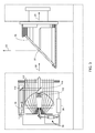
- FIG. 1 is a perspective view of a laser scanner in accordance with an embodiment of the invention
- FIG. 2 is a side view of the laser scanner illustrating a method of measurement
- FIG. 3 is a schematic illustration of the optical, mechanical, and electrical components of the laser scanner
- FIG. 4 depicts a planar view of a 3D scanned image
- FIG. 5 depicts an embodiment of a panoramic view of a 3D scanned image generated by mapping a planar view onto a sphere
- FIGS. 6A, 6B and 6C depict a embodiments of a 3D view of a 3D scanned image
- FIG. 7 depicts an embodiment of a 3D view made up of an image of the object of FIG. 6B but viewed from a different perspective and shown only partially;
- FIG. 8A is a perspective view of a 3D measuring device according to an embodiment
- FIG. 8B is a front view of a 3D scanner used to collect 3D coordinate data while scanning along a horizontal plane according to an embodiment
- FIG. 9 is a block diagram depicting a processor system according to an embodiment
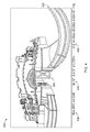
- FIG. 10 is a schematic representation of a 3D scanner measuring an object from two registration positions according to an embodiment
- FIG. 11 is a schematic representation of a 3D scanner measuring the object by scanning along a horizontal plane from a plurality of intermediate positions according to an embodiment
- FIG. 12 shows a 3D scanner capturing portions of the object by scanning along a horizontal plane from a plurality of positions according to an embodiment
- FIG. 13 shows the 3D scanner capturing portions of the object by scanning along a horizontal plane from a plurality of positions, as seen from a frame of reference of the 3D scanner, according to an embodiment
- FIGS. 14A, 14B and 14C illustrate a method for finding changes in the position and orientation of the 3D scanner over time according to an embodiment
- FIG. 15 includes steps in a method for measuring and registering 3D coordinates with a 3D measuring device according to an embodiment
- FIG. 16 is a perspective view of a 3D measuring device that includes a 3D scanner, 2D scanner, computing devices, and moveable platform according to an embodiment
- FIG. 17 includes steps in a method for measuring and registering 3D coordinates with a 3D measuring device according to an embodiment.
- the present invention relates to a device that includes a 3D scanner used in two modes, a first mode in which 3D coordinates of an object surface are obtained over points over a 3D region of space and a second mode in which 3D coordinates of an object surface are collected along a horizontal plane, where the two modes of the 3D scanner are used together to provide automatic registration of 3D scans over a 3D region of space encompassing more than one scan of 3D regions of space.
- the laser scanner 20 is shown for optically scanning and measuring the environment surrounding the laser scanner 20 .
- the laser scanner 20 has a measuring head 22 and a base 24 .
- the measuring head 22 is mounted on the base 24 such that the laser scanner 20 may be rotated about a vertical axis 23 .
- the measuring head 22 includes a gimbal point 27 that is a center of rotation about the vertical axis 23 and a horizontal axis 25 .
- the measuring head 22 has a rotary mirror 26 , which may be rotated about the horizontal axis 25 .
- the rotation about the vertical axis may be about the center of the base 24 .
- the terms vertical axis and horizontal axis refer to the scanner in its normal upright position.
- azimuth axis and zenith axis may be substituted for the terms vertical axis and horizontal axis, respectively.
- pan axis or standing axis may also be used as an alternative to vertical axis.
- the measuring head 22 is further provided with an electromagnetic radiation emitter, such as light emitter 28 , for example, that emits an emitted light beam 30 .
- the emitted light beam 30 is a coherent light beam such as a laser beam.
- the laser beam may have a wavelength range of approximately 300 to 1600 nanometers, for example 790 nanometers, 905 nanometers, 1550 nanometers, or less than 400 nanometers. It should be appreciated that other electromagnetic radiation beams having greater or smaller wavelengths may also be used.
- the emitted light beam 30 is amplitude or intensity modulated, for example, with a sinusoidal waveform or with a rectangular waveform.
- the emitted light beam 30 is emitted by the light emitter 28 onto the rotary mirror 26 , where it is deflected to the environment.
- a reflected light beam 32 is reflected from the environment by an object 34 .
- the reflected or scattered light is intercepted by the rotary mirror 26 and directed into a light receiver 36 .
- the directions of the emitted light beam 30 and the reflected light beam 32 result from the angular positions of the rotary mirror 26 and the measuring head 22 about the axes 25 and 23 , respectively. These angular positions in turn depend on the corresponding rotary drives or motors.
- Coupled to the light emitter 28 and the light receiver 36 is a controller 38 .
- the controller 38 determines, for a multitude of measuring points X, a corresponding number of distances d between the laser scanner 20 and the points X on object 34 .
- the distance to a particular point X is determined based at least in part on the speed of light in air through which electromagnetic radiation propagates from the device to the object point X.
- the phase shift of modulation in light emitted by the laser scanner 20 and the point X is determined and evaluated to obtain a measured distance d.
- the speed of light in air depends on the properties of the air such as the air temperature, barometric pressure, relative humidity, and concentration of carbon dioxide. Such air properties influence the index of refraction n of the air.
- a laser scanner of the type discussed herein is based on the time-of-flight (TOF) of the light in the air (the round-trip time for the light to travel from the device to the object and back to the device).
- TOF time-of-flight
- TOF scanners examples include scanners that measure round trip time using the time interval between emitted and returning pulses (pulsed TOF scanners), scanners that modulate light sinusoidally and measure phase shift of the returning light (phase-based scanners), as well as many other types.
- a method of measuring distance based on the time-of-flight of light depends on the speed of light in air and is therefore easily distinguished from methods of measuring distance based on triangulation.
- Triangulation-based methods involve projecting light from a light source along a particular direction and then intercepting the light on a camera pixel along a particular direction.
- the method of triangulation enables the distance to the object to be determined based on one known length and two known angles of a triangle.
- the method of triangulation does not directly depend on the speed of light in air.
- the scanning of the volume around the laser scanner 20 takes place by rotating the rotary mirror 26 relatively quickly about axis 25 while rotating the measuring head 22 relatively slowly about axis 23 , thereby moving the assembly in a spiral pattern.
- the rotary mirror rotates at a maximum speed of 5820 revolutions per minute.
- the gimbal point 27 defines the origin of the local stationary reference system.
- the base 24 rests in this local stationary reference system.
- the scanner 20 may also collect gray-scale information related to the received optical power (equivalent to the term “brightness.”)
- the gray-scale value may be determined at least in part, for example, by integration of the bandpass-filtered and amplified signal in the light receiver 36 over a measuring period attributed to the object point X.
- the measuring head 22 may include a display device 40 integrated into the laser scanner 20 .
- the display device 40 may include a graphical touch screen 41 , as shown in FIG. 1 , which allows the operator to set the parameters or initiate the operation of the laser scanner 20 .
- the screen 41 may have a user interface that allows the operator to provide measurement instructions to the device, and the screen may also display measurement results.
- the laser scanner 20 includes a carrying structure 42 that provides a frame for the measuring head 22 and a platform for attaching the components of the laser scanner 20 .
- the carrying structure 42 is made from a metal such as aluminum.
- the carrying structure 42 includes a traverse member 44 having a pair of walls 46 , 48 on opposing ends. The walls 46 , 48 are parallel to each other and extend in a direction opposite the base 24 .
- Shells 50 , 52 are coupled to the walls 46 , 48 and cover the components of the laser scanner 20 .
- the shells 50 , 52 are made from a plastic material, such as polycarbonate or polyethylene for example. The shells 50 , 52 cooperate with the walls 46 , 48 to form a housing for the laser scanner 20 .
- a pair of yokes 54 , 56 are arranged to partially cover the respective shells 50 , 52 .
- the yokes 54 , 56 are made from a suitably durable material, such as aluminum for example, that assists in protecting the shells 50 , 52 during transport and operation.
- the yokes 54 , 56 each includes a first arm portion 58 that is coupled, such as with a fastener for example, to the traverse 44 adjacent the base 24 .
- the arm portion 58 for each yoke 54 , 56 extends from the traverse 44 obliquely to an outer corner of the respective shell 50 , 52 .
- the yokes 54 , 56 extend along the side edge of the shell to an opposite outer corner of the shell.
- Each yoke 54 , 56 further includes a second arm portion that extends obliquely to the walls 46 , 48 . It should be appreciated that the yokes 54 , 56 may be coupled to the traverse 42 , the walls 46 , 48 and the shells 50 , 52 at multiple locations.
- the pair of yokes 54 , 56 cooperate to circumscribe a convex space within which the two shells 50 , 52 are arranged.
- the yokes 54 , 56 cooperate to cover all of the outer edges of the shells 50 , 54 , while the top and bottom arm portions project over at least a portion of the top and bottom edges of the shells 50 , 52 .
- This provides advantages in protecting the shells 50 , 52 and the measuring head 22 from damage during transportation and operation.
- the yokes 54 , 56 may include additional features, such as handles to facilitate the carrying of the laser scanner 20 or attachment points for accessories for example.
- a prism 60 is provided on top of the traverse 44 .
- the prism extends parallel to the walls 46 , 48 .
- the prism 60 is integrally formed as part of the carrying structure 42 .
- the prism 60 is a separate component that is coupled to the traverse 44 .
- the measured distances d may depend on signal strength, which may be measured in optical power entering the scanner or optical power entering optical detectors within the light receiver 36 , for example.
- a distance correction is stored in the scanner as a function (possibly a nonlinear function) of distance to a measured point and optical power (generally unscaled quantity of light power sometimes referred to as “brightness”) returned from the measured point and sent to an optical detector in the light receiver 36 . Since the prism 60 is at a known distance from the gimbal point 27 , the measured optical power level of light reflected by the prism 60 may be used to correct distance measurements for other measured points, thereby allowing for compensation to correct for the effects of environmental variables such as temperature. In the exemplary embodiment, the resulting correction of distance is performed by the controller 38 .
- the base 24 is coupled to a swivel assembly (not shown) such as that described in commonly owned U.S. Pat. No. 8,705,012 ('012), which is incorporated by reference herein.
- the swivel assembly is housed within the carrying structure 42 and includes a motor that is configured to rotate the measuring head 22 about the axis 23 .
- An auxiliary image acquisition device 66 may be a device that captures and measures a parameter associated with the scanned volume or the scanned object and provides a signal representing the measured quantities over an image acquisition area.
- the auxiliary image acquisition device 66 may be, but is not limited to, a pyrometer, a thermal imager, an ionizing radiation detector, or a millimeter-wave detector.
- the auxiliary image acquisition device 66 is a color camera.
- a central color camera (first image acquisition device) 112 is located internally to the scanner and may have the same optical axis as the 3D scanner device.
- the first image acquisition device 112 is integrated into the measuring head 22 and arranged to acquire images along the same optical pathway as emitted light beam 30 and reflected light beam 32 .
- the light from the light emitter 28 reflects off a fixed mirror 116 and travels to dichroic beam-splitter 118 that reflects the light 117 from the light emitter 28 onto the rotary mirror 26 .
- the dichroic beam-splitter 118 allows light to pass through at wavelengths different than the wavelength of light 117 .
- the light emitter 28 may be a near infrared laser light (for example, light at wavelengths of 780 nm or 1150 nm), with the dichroic beam-splitter 118 configured to reflect the infrared laser light while allowing visible light (e.g., wavelengths of 400 to 700 nm) to transmit through.
- the determination of whether the light passes through the beam-splitter 118 or is reflected depends on the polarization of the light.
- the digital camera 112 takes 2D photographic images of the scanned area to capture color data to add to the scanned image.
- the direction of the camera view may be easily obtained by simply adjusting the steering mechanisms of the scanner—for example, by adjusting the azimuth angle about the axis 23 and by steering the mirror 26 about the axis 25 .
- FIG. 4 depicts an example of a planar view of a 3D scanned image 400 .
- the planar view depicted in FIG. 4 maps an image based on direct mapping of data collected by the scanner.
- the scanner collects data in a spherical pattern but with data points collected near the poles more tightly compressed than those collected nearer the horizon. In other words, each point collected near a pole represents a smaller solid angle than does each point collected nearer the horizon. Since data from the scanner may be directly represented in rows and column, data in a planar image is conveniently presented in a rectilinear format, as shown in FIG. 4 .
- the planar view may be a 3D unprocessed scanned image displaying just the gray-scale values received from the distance sensor arranged in columns and rows as they were recorded.
- the 3D unprocessed scanned image of the planar view may be in full resolution or reduced resolution depending on system characteristics (e.g., display device, storage, processor).
- the planar view may be a 3D processed scanned image that depicts either gray-scale values (resulting from the light irradiance measured by the distance sensor for each pixel) or color values (resulting from camera images which have been mapped onto the scan).
- FIG. 4 is shown as a line drawing for clarity in document reproduction.
- the user interface associated with the display unit which may be integral to the laser scanner, may provide a point selection mechanism, which in FIG. 4 is the cursor 410 .
- the point selection mechanism may be used to reveal dimensional information about the volume of space being measured by the laser scanner.
- the row and column at the location of the cursor are indicated on the display at 430 .
- the two measured angles and one measured distance (the 3D coordinates in a spherical coordinate system) at the cursor location are indicated on the display at 440 .
- Cartesian XYZ coordinate representations of the cursor location are indicated on the display at 450 .
- FIG. 5 depicts an example of a panoramic view of a 3D scanned image 600 generated by mapping a planar view onto a sphere, or in some cases a cylinder.
- a panoramic view can be a 3D processed scanned image (such as that shown in FIG. 5 ) in which 3D information (e.g., 3D coordinates) is available.
- the panoramic view may be in full resolution or reduced resolution depending on system characteristics.
- an image such as FIG. 5 is a 2D image that represents a 3D scene when viewed from a particular perspective. In this sense, the image of FIG. 5 is much like an image that might be captured by a 2D camera or a human eye.
- the panoramic view extracted from the 3D scanner is ordinarily a gray-scale or color image
- FIG. 5 is shown as a line drawing for clarity in document reproduction.
- panoramic view refers to a display in which angular movement is generally possible about a point in space, but translational movement is not possible (for a single panoramic image).
- 3D view refers to generally refers to a display in which provision is made (through user controls) to enable not only rotation about a fixed point but also translational movement from point to point in space.
- FIGS. 6A, 6B and 6C depict an example of a 3D view of a 3D scanned image.
- the 3D view is an example of a 3D processed scanned image.
- the 3D view may be in full resolution or reduced resolution depending on system characteristics.
- the 3D view allows multiple registered scans to be displayed in one view.
- FIG. 6A is a 3D view 710 over which a selection mask 730 has been placed by a user.
- FIG. 6B is a 3D view 740 in which only that part of the 3D view 710 covered by the selection mask 730 has been retained.
- FIG. 6C shows the same 3D measurement data as in FIG.
- FIG. 7 shows a different view of FIG. 6B , the view in this instance being obtained from a translation and rotation of the observer viewpoint, as well as a reduction in observed area.
- the 3D views extracted from the 3D scanner is ordinarily a gray-scale or color image
- FIGS. 6A-C and 7 are shown as line drawings for clarity in document reproduction.
- FIGS. 8A, 8B and 9 show an embodiment of a 3D measuring device 800 that includes a 3D scanner 20 , a processor system 950 , and an optional moveable platform 820 .
- the 3D measuring device 800 may be a 3D TOF scanner 20 as described in reference to FIG. 1 .
- the processor system 950 includes one or more processing elements that may include a 3D scanner processor (controller) 38 , an external computer 970 , and a cloud computer 980 .
- the processors may be microprocessors, field programmable gate arrays (FPGAs), digital signal processors (DSPs), and generally any device capable of performing computing functions.
- the one or more processors have access to memory for storing information.
- the controller 38 represents one or more processors distributed throughout the 3D scanner.
- an external computer 970 and one or more cloud computers 980 for remote computing capability.
- only one or two of the processors 38 , 970 , and 980 is provided in the processor system. Communication among the processors may through wired links, wireless links, or a combination of wired and wireless links.
- scan results are uploaded after each scanning session to the cloud (remote network) for storage and future use.
- the 3D scanner 20 measures 2D coordinates in a horizontal plane. In most cases, it does this by steering light within a horizontal plane to illuminate object points in the environment. It collects the reflected (scattered) light from the objects points to determine 2D coordinates of the object points in the horizontal plane.
- the 3D scanner scans a spot of light measures the angle of rotation about the axis 23 with an angular encoder while at the same time measuring a corresponding distance value to each illuminated object point in the horizontal plane.
- the 3D scanner 23 may rotate about the axis 23 at a relatively high speed while performing no rotation about the axis 25 .
- the laser power is set to fall within eye safety limits.
- An optional position/orientation sensor 920 in the 3D scanner 20 may include inclinometers (accelerometers), gyroscopes, magnetometers, and altimeters.
- inclinometers accelerometers
- gyroscopes magnetometers
- altimeters usually devices that include one or more of an inclinometer and gyroscope are referred to as an inertial measurement unit (IMU).
- IMU inertial measurement unit
- the term IMU is used in a broader sense to include a variety of additional devices that indicate position and/or orientation—for example, magnetometers that indicate heading based on changes in magnetic field direction relative to the earth's magnetic north and altimeters that indicate altitude (height).
- An example of a widely used altimeter is a pressure sensor.
- the optional moveable platform 820 enables the 3D measuring device 20 to be moved from place to place, typically along a floor that is approximately horizontal.
- the optional moveable platform 820 is a tripod that includes wheels 822 .
- the wheels 822 may be locked in place using wheel brakes 824 .
- the wheels 822 are retractable, enabling the tripod to sit stably on three feet attached to the tripod.
- the tripod has no wheels but is simply pushed or pulled along a surface that is approximately horizontal, for example, a floor.
- the optional moveable platform 820 is a wheeled cart that may be hand pushed/pulled or motorized.
- the 3D scanner 20 in one mode of operation, is configured to scan a beam of light over a range of angles in a horizontal plane. At instants in time the 3D scanner 20 returns an angle reading and a corresponding distance reading to provide 2D coordinates of object points in the horizontal plane. In completing one scan over the full range of angles, the 3D scanner 20 returns a collection of paired angle and distance readings. As the 3D measuring device 800 is moved from place to place, it continues to return 2D coordinate values in a horizontal plane. These 2D coordinate values are used to locate the position of the 3D scanner 20 at each stationary registration position, thereby enabling more accurate registration.
- FIG. 10 shows the 3D measuring device 800 moved to a first registration position 1112 in front of an object 1102 that is to be measured.
- the object 1102 might for example be a wall in a room.
- the 3D measuring device 800 is brought to a stop and is held in place with brakes, which in an embodiment are brakes 824 on wheels 822 .
- the 3D scanner 20 in the 3D measuring device 800 takes a first 3D scan of the object 1102 .
- the 3D scanner 20 may if desired obtain 3D measurements in all directions except in downward directions blocked by the structure of the 3D measuring device 800 .
- a smaller effective FOV 1130 may be selected to provide a more face-on view of features on the structure.
- the processor system 950 causes the 3D scanner 20 to change from 3D scanning mode to 2D scanning mode. In an embodiment, it does this by fixing the mirror 26 to direct the outgoing beam 30 on a horizontal plane. The mirror receives reflected light 32 traveling in the reverse direction.
- the scanner begins the 2D scan as soon as the 3D scanning stops.
- the 2D scan starts when the processor receives a signal such as a signal form the position/orientation sensor 920 , a signal from a brake release sensor, or a signal sent in response to a command from an operator.
- the 3D scanner 20 may start to collect 2D scan data when the 3D measuring device 800 starts to move. In an embodiment, the 2D scan data is sent to the processor system 950 as it is collected.
- the 2D scan data is collected as the 3D measuring device 800 is moved toward the second registration position 1114 .
- 2D scan data is collected and processed as the 3D scanner 20 passes through a plurality of 2D measuring positions 1120 .
- the 3D scanner collects 2D coordinate data over an effective FOV 1140 .
- the processor system 950 uses 2D scan data from the plurality of 2D scans at positions 1120 to determine a position and orientation of the 3D scanner 20 at the second registration position 1114 relative to the first registration position 1112 , where the first registration position and the second registration position are known in a 3D coordinate system common to both.
- the common coordinate system is represented by 2D Cartesian coordinates x, y and by an angle of rotation ⁇ relative to the x or y axis.
- the x and y axes lie in the horizontal x-y plane of the 3D scanner 20 and may be further based on a direction of a “front” of the 3D scanner 20 .
- An example of such an (x, y, ⁇ ) coordinate system is the coordinate system 1410 of FIG. 14A .
- the object 1102 there is a region of overlap 1150 between the first 3D scan (collected at the first registration position 1112 ) and the second 3D scan (collected at the second registration position 1114 ).
- the overlap region 1150 there are registration targets (which may be natural features of the object 1102 ) that are seen in both the first 3D scan and the second 3D scan.
- a problem that often occurs in practice is that, in moving the 3D scanner 20 from the first registration position 1112 to the second registration position 1114 , the processor system 950 loses track of the position and orientation of the 3D scanner 20 and hence is unable to correctly associate the registration targets in the overlap regions to enable the registration procedure to be performed reliably.
- the processor system 950 is able to determine the position and orientation of the 3D scanner 20 at the second registration position 1114 relative to the first registration position 1112 . This information enables the processor system 950 to correctly match registration targets in the region of overlap 1150 , thereby enabling the registration procedure to be properly completed.
- FIG. 12 shows the 3D scanner 20 collecting 2D scan data at selected positions 1120 over an effective FOV 1140 . At different positions 1120 , the 3D scanner captures 2D scan data over a portion of the object 1102 marked A, B, C, D, and E. FIG. 12 shows the 3D scanner 20 moving in time relative to a fixed frame of reference of the object 1102 .
- FIG. 13 includes the same information as FIG. 12 but shows it from the frame of reference of the 3D scanner 20 while taking 2D scans rather than the frame of reference of the object 1102 .
- This figure makes clear that in the scanner frame of reference, the position of features on the object change over time. Hence it is clear that the distance traveled by the 3D scanner 20 between registration position 1 and registration position 2 can be determined from the 2D scan data sent from the 3D scanner 20 to the processor system 950 .
- FIG. 14A shows a coordinate system that may be used in FIGS. 14B and 14C .
- the 2D coordinates x and y are selected to lie on the plane in which the 2D scans are taken, ordinarily the horizontal plane.
- the angle ⁇ is selected as a rotation angle in the plane, the rotation angle relative to an axis such as x or y.
- FIGS. 14B, 14C represent a realistic case in which the 3D scanner 20 is moved not exactly on a straight line, say nominally parallel to the object 1102 , but also to the side. Furthermore, the 3D scanner 20 may be rotated as it is moved.
- FIG. 14B shows the movement of the object 1102 as seen from the frame of reference of the 3D scanner 20 in traveling from the first registration position to the second registration position.
- the scanner frame of reference that is, as seen from the scanner's point of view
- the object 1102 is moving while the 3D scanner 20 is fixed in place.
- the portions of the object 1102 seen by the 3D scanner 20 appear to translate and rotate in time.
- the 3D scanner 20 provides a succession of such translated and rotated 2D scans to the processor system 950 .
- the scanner translates in the +y direction by a distance 1420 shown in FIG. 14B and rotates by an angle 1430 , which in this example is +5 degrees.
- the scanner could equally well have moved in the +x or ⁇ x direction by a small amount.
- the processor system 950 uses the data recorded in successive horizontal scans as seen in the frame of reference of the scanner 20 , as shown in FIG. 14B .
- the processor system 950 performs a best-fit calculation using methods well known in the art to match the two scans or features in the two scans as closely as possible.
- the processor system 950 keeps track of the translation and rotation of the 3D scanner 20 . In this way, the processor system 950 is able to accurately determine the change in the values of x, y, ⁇ as the measuring device 800 moves from the first registration position 1112 to the second registration position 1114 .
- the processor system 950 determines the position and orientation of the 3D measuring device 800 based on a comparison of the succession of 2D scans and not on fusion of the 2D scan data with 3D scan data provided by the 3D scanner 20 at the first registration position 1112 or the second registration position 1114 .
- the processor system 950 is configured to determine a first translation value, a second translation value, and a first rotation value that, when applied to a combination of the first 2D scan data and second 2D scan data, results in transformed first 2D data that matches transformed second 2D data as closely as possible according to an objective mathematical criterion.
- the translation and rotation may be applied to the first scan data, the second scan data, or to a combination of the two.
- a translation applied to the first data set is equivalent to a negative of the translation applied to the second data set in the sense that both actions produce the same match in the transformed data sets.
- An example of an “objective mathematical criterion” is that of minimizing the sum of squared residual errors for those portions of the scan data judged to overlap.
- Another type of objective mathematical criterion may involve a matching of multiple features identified on the object. For example, such features might be the edge transitions 1103 , 1104 , and 1105 shown in FIG. 11B .
- the mathematical criterion may involve processing of the raw 2D scan data provided by the 3D scanner 20 to the processor system 950 , or it may involve a first intermediate level of processing in which features are represented as a collection of line segments using methods that are known in the art, for example, methods based on the Iterative Closest Point (ICP).
- ICP Iterative Closest Point
- the first translation value is dx
- the second translation value is dy
- the processor system 950 is further configured to determine a third translation value (for example, dz) and a second and third rotation values (for example, pitch and roll). The third translation value, second rotation value, and third rotation value may be determined based at least in part on readings from the position/orientation sensor 920 .
- the 3D scanner 20 collects 2D scan data at the first registration position 1112 and more 2D scan data at the second registration position 1114 . In some cases, these 2D scans may suffice to determine the position and orientation of the 3D measuring device at the second registration position 1114 relative to the first registration position 1112 . In other cases, the two sets of 2D scan data are not sufficient to enable the processor system 950 to accurately determine the first translation value, the second translation value, and the first rotation value. This problem may be avoided by collecting 2D scan data at intermediate scan locations 1120 . In an embodiment, the 2D scan data is collected and processed at regular intervals, for example, once per second. In this way, features are easily identified in successive 2D scans 1120 .
- the processor system 950 may choose to use the information from all the successive 2D scans in determining the translation and rotation values in moving from the first registration position 1112 to the second registration position 1114 .
- the processor may choose to use only the first and last scans in the final calculation, simply using the intermediate 2D scans to ensure proper correspondence of matching features. In most cases, accuracy of matching is improved by incorporating information from multiple successive 2D scans.
- the 3D measuring device 800 is moved to the second registration position 1114 .
- the 3D measuring device 800 is brought to a stop and brakes are locked to hold the 3D scanner stationary.
- the processor system 950 starts the 3D scan automatically when the moveable platform is brought to a stop, for example, by the position/orientation sensor 920 noting the lack of movement.
- the 3D scanner 20 in the 3D measuring device 800 takes a 3D scan of the object 1102 . This 3D scan is referred to as the second 3D scan to distinguish it from the first 3D scan taken at the first registration position.
- the processor system 950 applies the already calculated first translation value, the second translation value, and the first rotation value to adjust the position and orientation of the second 3D scan relative to the first 3D scan.
- This adjustment which may be considered to provide a “first alignment,” brings the registration targets (which may be natural features in the overlap region 1150 ) into close proximity.
- the processor system 950 performs a fine registration in which it makes fine adjustments to the six degrees of freedom of the second 3D scan relative to the first 3D scan. It makes the fine adjustment based on an objective mathematical criterion, which may be the same as or different than the mathematical criterion applied to the 2D scan data.
- the objective mathematical criterion may be that of minimizing the sum of squared residual errors for those portions of the scan data judged to overlap.
- the objective mathematical criterion may be applied to a plurality of features in the overlap region.
- the mathematical calculations in the registration may be applied to raw 3D scan data or to geometrical representations of the 3D scan data, for example, by a collection of line segments.
- the aligned values of the first 3D scan and the second 3D scan are combined in a registered 3D data set.
- the 3D scan values included in the registered 3D data set are based on some combination of 3D scanner data from the aligned values of the first 3D scan and the second 3D scan.
- FIG. 15 shows elements of a method 1500 for measuring and registering 3D coordinates.
- An element 1505 includes providing a 3D measuring device that includes a processor system, a 3D scanner, and a moveable platform.
- the processor system has at least one of a 3D scanner controller, an external computer, and a cloud computer configured for remote network access. Any of these processing elements within the processor system may include a single processor or multiple distributed processing elements, the processing elements being a microprocessor, digital signal processor, FPGA, or any other type of computing device.
- the processing elements have access to computer memory.
- the 3D scanner has a first light source, a first beam steering unit, a first angle measuring device, a second angle measuring device, and a first light receiver.
- the first light source is configured to emit a first beam of light, which in an embodiment is a beam of laser light.
- the first beam steering unit is provided to steer the first beam of light to a first direction onto a first object point.
- the beam steering unit may be a rotating mirror such as the mirror 26 or it may be another type of beam steering mechanism.
- the 3D scanner may contain a base onto which is placed a first structure that rotates about a vertical axis, and onto this structure may be placed a second structure that rotates about a horizontal axis. With this type of mechanical assembly, the beam of light may be emitted directly from the second structure and point in a desired direction. Many other types of beam steering mechanisms are possible. In most cases, a beam steering mechanism includes one or two motors.
- the first direction is determined by a first angle of rotation about a first axis and a second angle of rotation about a second axis.
- the first angle measuring device is configured to measure the first angle of rotation and the second angle measuring device configured to measure the second angle of rotation.
- the first light receiver is configured to receive first reflected light, the first reflected light being a portion of the first beam of light reflected by the first object point.
- the first light receiver is further configured to produce a first electrical signal in response to the first reflected light.
- the first light receiver is further configured to cooperate with the processor system to determine a first distance to the first object point based at least in part on the first electrical signal
- the 3D scanner is configured to cooperate with the processor system to determine 3D coordinates of the first object point based at least in part on the first distance, the first angle of rotation and the second angle of rotation.
- the moveable platform is configured to carry the 3D scanner.
- An element 1510 includes determining with processor system, in cooperation with the 3D scanner, 3D coordinates of a first collection of points on an object surface while the 3D scanner is fixedly located at a first registration position.
- An element 1515 includes obtaining by the 3D scanner in cooperation with the processor system a plurality of 2D scan sets.
- Each of the plurality of 2D scan sets is a set of 2D coordinates of points on the object surface collected as the 3D scanner moves from the first registration position to a second registration position.
- Each of the plurality of 2D scan sets is collected by the 3D scanner at a different position relative to the first registration position.
- each 2D scan set lies in a horizontal plane.
- An element 1520 includes determining by the processor system a first translation value corresponding to a first translation direction, a second translation value corresponding to a second translation direction, and a first rotation value corresponding to a first orientational axis, wherein the first translation value, the second translation value, and the first rotation value are determined based at least in part on a fitting of the plurality of 2D scan sets according to a first mathematical criterion.
- the first orientation axis is a vertical axis perpendicular to the planes in which the 2D scan sets are collected.
- An element 1525 includes determining with the processor system, in cooperation with the 3D scanner, 3D coordinates of a second collection of points on the object surface while the 3D scanner is fixedly located at the second registration position.
- An element 1535 includes identifying by the processor system a correspondence among registration targets present in both the first collection of points and the second collection of points, the correspondence based at least in part on the first translation value, the second translation value, and the first rotation value;
- An element 1545 includes determining 3D coordinates of a registered 3D collection of points based at least in part on a second mathematical criterion, the correspondence among registration targets, the 3D coordinates of the first collection of points, and the 3D coordinates of the second collection of points.
- An element 1550 includes storing the 3D coordinates of the registered 3D collection of points.
- processing of 2D and 3D scanner data is performed as the measurement is taking place, thereby eliminating time-consuming post processing and further ensuring that required scan data has been collected before leaving a site.
- FIG. 16 An example of a measuring device 800 that may be used to perform this measurement was described herein above with reference to FIG. 8 .
- a measuring device 1600 that may be used to perform this measurement is now described with reference to FIG. 16 .
- the 3D measuring device 1600 includes a 3D TOF scanner 20 that measures distance based at least in part on a speed of light in air. This type of scanner also measures two angles using angle transducers such as angular encoders. The two measured angles and one measured distance provide 3D coordinates of points on an object.
- the scanner includes motors and a servo system to drive a beam of light to any desired point on an object.
- the scanner may also include a mode for rapidly directing the beam of light over a continually varying pattern, thereby enabling rapid collection of 3D coordinates over a large volume.
- the 3D measuring device 20 is further configured to emit a beam of light in a plane 1622 , which might be a horizontal plane. In an embodiment, the beam of light sweeps over an angle of 360 degrees at a rate of 10 Hz. In an embodiment, the 3D scanner 20 emits a beam of light on an object, receives reflected light from the object, and determines a collection of distances to the object based on the reflected light. In an embodiment, in its planar-emission mode, the 3D scanner 1610 measures distances as a function of swept angle. In an embodiment, the 3D measuring device further includes an assembly 1620 having a computing device 1630 that receives from the 3D scanner 20 the 2D scan sets and the 3D coordinate data.
- the computing device 1630 further performs processing of 2D and 3D scan data to determine a correspondence among targets measured at the first registration position and the second registration position.
- other computing devices such as a computer 1640 or an external computer 1650 not attached to the 3D measuring device may be used to determine the correspondence among targets measured at the first and second registration positions.
- all processing of 3D and 2D data are carried out by an internal processor within the 3D measuring device 20 .
- Communication channels to transfer information among the 2D scanner, 3D scanner, and computing devices may be wireless or wired communication channels 1660 .
- a wireless access point is contained within the 3D scanner 20 .
- the AP connects to wireless devices such as the 2D scanner 1610 and one or more of computing devices 1630 , 1640 , and 1650 .
- the 3D scanner 20 includes an automation adapter having an Ethernet interface and a switch.
- the automation adapter connects with Ethernet cables of the 2D scanner 1610 and computing devices such as 1630 , 1640 , and 1650 .
- the automation interface enables wired communication among the elements of the measuring device 1600 and external computing devices.
- the 3D scanner 20 includes both an AP and an automation adapter to provide both wireless and wired communication among different components of the system. In other embodiments, the AP and automation adapter are not included in the 3D scanner 20 but elsewhere in the system.
- the measuring device further includes a moveable platform 1605 , which may be pushed by an operator or moved under computer control by motorized wheels.
- the 3D scanner is mounted on the moveable platform 1605 .
- a first 3D scan is taken at a first registration position.
- the scanner moves between the first registration position and the second registration position, either under its own power using motorized wheels or being pushed by an operator.
- the 3D scanner obtains 2D scan data, which is then evaluated mathematically to determine a movement vector (distance in each of two directions) and an angle of rotation, as explained herein above.
- the 3D scanner 20 takes a second 3D scan.
- one of the computing devices i.e., processors
- a computing device performs any other steps needed to complete combining and processing of the 3D data collected at the first and second registration positions. This process of combining may further include additional collected data such as color data obtained from an internal color camera within the scanner.
- the measuring device 1600 moves to successive registration positions, taking a 3D measurement at each registration position and collecting 2D data by emitting light in a planar mode between the registration positions.
- An aspect of the present invention is that processing is carried out between the second and third registration positions to determine the correspondence between the registration targets observed at the first and second registration positions. This processing uses the 2D data collected between the first and second registration positions in combination with 3D data obtained at the first and second registration positions.
- the computing device will have determined (at least partially if not completely) the correspondence among the targets in the first and second registration positions. If a correspondence was not successfully established by the computing device, a notice may be given indicating that the problem is present. This may result in an operator being notified or it may result in the measurement suspended. In an embodiment, the failure to register the targets observed by the 3D scanner at the first and second registration positions results in the scanner being returned to an earlier step to repeat measurements.
- the measuring device when the computing device has determined the correspondence among the targets in the overlap region of the first and second registration positions, the measuring device further determines a quality of the correspondence. In an embodiment, the measuring device provides a notification when the quality of the correspondence is below a quality threshold. The notification may be a notification to the user, a computer message, an emitted sound, an emitted light, or a stopping of the inspection procedure, for example.
- the scanner may determine the distance to move the measuring device 1600 between the first registration position and the second registration position based at least in part on one of the 2D scan sets.
- each of the 2D scan sets includes information about features observable in a horizontal 2D scan. Examples of such features are the features 1102 - 1105 in FIG. 11 .
- the decision on the distance to be moved between the first registration position and the second registration position is based entirely on the first 2D scan set collected between the first and second registration positions.
- the decision on the distance to be moved is based on a plurality of the first 2D scan sets, with the decision on the distance to be moved made during the movement between the first and second registration positions.
- the computing device 1640 is a laptop or notebook computer that provides a user an interface to a computer program enabling advanced processing and viewing of scan data. In an embodiment, use of the computing device 1640 is optional and simply is provided to give the operator more analysis tools. In another embodiment, the computing device 1640 is used to perform correspondence calculations described herein above or to perform other 3D processing steps.
- a computing device 1630 continually computes the position of the measuring device 1600 based at least in part on data from the 2D scanner and, optionally, on data provided by a position/orientation sensor, which might include a multi-axis inclinometer, a multi-axis gyroscope, and a magnetometer (electronic compass) to provide heading information.
- a position/orientation sensor which might include a multi-axis inclinometer, a multi-axis gyroscope, and a magnetometer (electronic compass) to provide heading information.
- data from the 2D scanner is acquired at a rate of 10 Hz.
- a difference is calculated with respect to one or more 2D scans obtained previously.
- this information is provided to a Kalman filter that performs “intelligent averaging” calculations that smooth out noise within constraints imposed by movement geometry.
- application software runs on a notebook computer 1640 or similar device.
- the user selects a button on the user interface of the application software to begin processing of the collected data.
- the software requests 2D position information from processed 2D scan data, which might be provided for example from the computing device 1630 .
- the processed 2D scan data may be provided as metadata to the 3D scan.
- the software uses a registration algorithm to determine a correspondence among the registration targets in the overlap region between the first and second registration positions.
- the software completes the 3D registration by combining 3D coordinates obtained at the first and second registration positions.
- the calculations are performed without the user needing to press a button on the user interface of an application program running on a notebook computer 1640 .
- measurements are carried out in an integrated and automatic way without requiring assistance of an operator.
- additional calculations which may involve including additional mathematical operations such as meshing registered 3D data, and adding and texture to registered 3D data may be carried out following the registration step.
- these later processing steps may be carried out in parallel, for example, by network computers to provide finished 3D scans at the end of data collection by the measuring device 1600 .
- FIG. 17 is a flow chart of a method 1700 that may be carried out according to the description given herein above.
- the measuring device 1600 is fixedly located in a first registration position such as the position 1112 in FIG. 10 .
- the measuring device includes a 3D scanner 20 configured to operate in both a 3D scanning mode and a 2D planer-scanner mode.
- the 3D scanner 20 is mounted on a moveable platform 1605 , which in FIG. 16 is a tripod mounted on a platform having three wheels.
- the 3D scanner in its planar-scanning mode, the 3D scanner emits a beam of light that sweeps in different directions in a horizontal plane 1622 .
- the 3D scanner while in the first registration position, obtains 3D coordinates of a first collection of points on an object, which in an embodiment illustrated in FIGS. 10 and 11 is the side of a building.
- the 3D scanner is a TOF scanner, which may be of a variety of types.
- An example of a possible TOF scanner is the scanner 20 discussed in reference to FIGS. 1-3 .
- the 3D scanner operates in its planer-scanning mode to obtain a first plurality of 2D scan sets while the first measuring device moves from the first registration position to the second registration position.
- Each of the first plurality of 2D scan sets includes a set of 2D coordinates of points on the object.
- the 2D coordinates of points on the object may be given in any coordinate system, for example, as x-y values or as distance and angle values.
- Each of the first plurality of 2D scan sets is collected by the 3D scanner at a different position relative to the first registration position.
- the measuring device determines a first translation value corresponding to a first translation direction, a second translation value corresponding to a second translation direction, and a first rotation value corresponding to a first orientational axis.
- the first translational direction and the second translational direction might be, for example, x-y coordinates in a coordinate system established with respect to the object being measured.
- the x-y coordinates might correspond to coordinates along a floor on which the measuring device moves.
- Other coordinate systems may alternatively be used to represent the first translational direction and the second translational direction.
- the first orientational axis has a given direction in relation to the first and second translation directions.
- a convenient choice for the first orientational axis is a direction perpendicular to the plane containing vectors along the first and second translational directions.
- the first translation value, the second translation value, and the first rotation angle provide the information needed to obtain a good initial estimate of the pose of the scanner at the second registration position relative to the pose of the scanner at the first registration position. This provides a good basis for matching the registration targets, whether natural targets or artificial targets, seen from the first and second registration positions.
- the determining of the first translation value, the second translation value, and the first rotation angle is carried out according to a first mathematical criterion.
- Such a mathematical criterion is also referred to as an objective mathematical criterion.
- the most commonly used such mathematical criterion is a least-squares criterion. In this case, for this criterion, the 2D features observed in the first collection of 2D scan sets are aligned so as to minimize the sum of squares of residual errors in the matching of the features.
- the 3D scanner while in the second registration position, obtains 3D coordinates of a second collection of points on the object.
- the first collection of points measured by the 3D scanner at the first registration position are not exactly the same points as the second collection of points measured by the 3D scanner at the second registration position.
- the points provide the information needed to identify the target features, which might be natural features or artificial features.
- the measuring device while moving from the second registration position to a third registration position, determines a correspondence among registration targets seen in the first collection of 3D points observed at the first registration position and the registration targets seen in the second collection of 3D points observed at the second registration position.
- This registration is based at least in part on the first translation value, the second translation value, and the first rotation value, which provide the initial conditions from which the mathematical matching of 3D feature is carried out.
- the first translation value, the second translation value, and the first rotation value are stored.
- processor controller, computer, DSP, FPGA are understood in this document to mean a computing device that may be located within an instrument, distributed in multiple elements throughout an instrument, or placed external to an instrument.
Abstract
A method for measuring and registering three-dimensional (3D) by measuring 3D coordinates with a 3D scanner in a first registration position, measuring two-dimensional (2D) coordinates with the 3D scanner by projecting a beam of light in plane onto the object while the 3D scanner moves from the first registration position to a second registration position, measuring 3D coordinates with the 3D scanner at the second registration position, and determining a correspondence among targets in the first and second registration positions while the 3D scanner moves between the second and third registration positions.
Description
The present application is a continuation-in-part of U.S. patent application Ser. No. 14/559,311, filed Dec. 3, 2014, which claims the benefit of International Patent Application No. PCT/IB2013/003082, filed Sep. 27, 2013, which claims the benefit of German Patent Application No. 10 2012 109 481.0, filed Oct. 5, 2012 and of U.S. Patent Application No. 61/716,845, filed Oct. 22, 2012, the contents of all of which are incorporated by reference herein.
U.S. Pat. No. 8,705,016 ('016) describes a laser scanner which, through use of a rotatable mirror, emits a light beam into its environment to generate a three-dimensional (3D) scan. The contents of this patent are incorporated herein by reference.
The subject matter disclosed herein relates to use of a 3D laser scanner time-of-flight (TOF) coordinate measurement device. A 3D laser scanner of this type steers a beam of light to a non-cooperative target such as a diffusely scattering surface of an object. A distance meter in the device measures a distance to the object, and angular encoders measure the angles of rotation of two axles in the device. The measured distance and two angles enable a processor in the device to determine the 3D coordinates of the target.
A TOF laser scanner is a scanner in which the distance to a target point is determined based on the speed of light in air between the scanner and a target point. Laser scanners are typically used for scanning closed or open spaces such as interior areas of buildings, industrial installations and tunnels. They may be used, for example, in industrial applications and accident reconstruction applications. A laser scanner optically scans and measures objects in a volume around the scanner through the acquisition of data points representing object surfaces within the volume. Such data points are obtained by transmitting a beam of light onto the objects and collecting the reflected or scattered light to determine the distance, two-angles (i.e., an azimuth and a zenith angle), and optionally a gray-scale value. This raw scan data is collected, stored and sent to a processor or processors to generate a 3D image representing the scanned area or object.
Generating an image requires at least three values for each data point. These three values may include the distance and two angles, or may be transformed values, such as the x, y, z coordinates. In an embodiment, an image is also based on a fourth gray-scale value, which is a value related to irradiance of scattered light returning to the scanner.
Most TOF scanners direct the beam of light within the measurement volume by steering the light with a beam steering mechanism. The beam steering mechanism includes a first motor that steers the beam of light about a first axis by a first angle that is measured by a first angular encoder (or other angle transducer). The beam steering mechanism also includes a second motor that steers the beam of light about a second axis by a second angle that is measured by a second angular encoder (or other angle transducer).
Many contemporary laser scanners include a camera mounted on the laser scanner for gathering camera digital images of the environment and for presenting the camera digital images to an operator of the laser scanner. By viewing the camera images, the operator of the scanner can determine the field of view of the measured volume and adjust settings on the laser scanner to measure over a larger or smaller region of space. In addition, the camera digital images may be transmitted to a processor to add color to the scanner image. To generate a color scanner image, at least three positional coordinates (such as x, y, z) and three color values (such as red, green, blue “RGB”) are collected for each data point.
A 3D image of a scene may require multiple scans from different registration positions. The overlapping scans are registered in a joint coordinate system, for example, as described in U.S. Published Patent Application No. 2012/0069352 ('352), the contents of which are incorporated herein by reference. Such registration is performed by matching targets in overlapping regions of the multiple scans. The targets may be artificial targets such as spheres or checkerboards or they may be natural features such as corners or edges of walls. Some registration procedures involve relatively time-consuming manual procedures such as identifying by a user each target and matching the targets obtained by the scanner in each of the different registration positions. Some registration procedures also require establishing an external “control network” of registration targets measured by an external device such as a total station. The registration method disclosed in '352 eliminates the need for user matching of registration targets and establishing of a control network.
However, even with the simplifications provided by the methods of '352, it is today still difficult to remove the need for a user to carry out the manual registration steps as described above. In a typical case, only 30% of 3D scans can be automatically registered to scans taken from other registration positions. Today such registration is seldom carried out at the site of the 3D measurement but instead in an office following the scanning procedure. In a typical case, a project requiring a week of scanning requires two to five days to manually register the multiple scans. This adds to the cost of the scanning project. Furthermore, the manual registration process sometimes reveals that the overlap between adjacent scans was insufficient to provide proper registration. In other cases, the manual registration process may reveal that certain sections of the scanning environment have been omitted. When such problems occur, the operator must return to the site to obtain additional scans. In some cases, it is not possible to return to a site. A building that was available for scanning at one time may be impossible to access at a later time. A forensics scene of an automobile accident or a homicide is often not available for taking of scans for more than a short time after the incident.
Accordingly, while existing 3D scanners are suitable for their intended purposes, what is needed is a 3D scanner having certain features of embodiments of the present invention.
According to one aspect of the invention, a method for measuring and registering three-dimensional (3D) coordinates comprises: fixedly locating a measuring device in a first registration position, the measuring device including a 3D scanner on a moveable platform; obtaining with the 3D scanner, while in the first registration position, 3D coordinates of a first collection of points on an object, the 3D scanner configured to determine the 3D coordinates of the first collection of points by projecting a beam of light onto the object and obtaining for each point in the first collection of points a distance and two angles in response, the distance based at least in part on a speed of light in air; obtaining by the 3D scanner a first plurality of 2D scan sets while the measuring device moves from the first registration position to a second registration position, each of the first plurality of 2D scan sets being a set of 2D coordinates of points on the object, each of the first plurality of 2D scan sets being collected by the 3D scanner at a different position relative to the first registration position; determining for the measuring device a first translation value corresponding to a first translation direction, a second translation value corresponding to a second translation direction, and a first rotation value corresponding to a first orientational axis, wherein the first translation value, the second translation value, and the first rotation value are determined based at least in part on a fitting of the first plurality of 2D scan sets according to a first mathematical criterion; obtaining with the 3D scanner, while in the second registration position, 3D coordinates of a second collection of points on the object; determining by the measuring device, while the measuring device moves from the second registration position to a third registration position, a correspondence among registration targets present in both the first collection of points and the second collection of points, the correspondence based at least in part on the first translation value, the second translation value, and the first rotation value; and storing the first translation value, the second translation value, and the first rotation value.
These and other advantages and features will become more apparent from the following description taken in conjunction with the drawings.
The subject matter, which is regarded as the invention, is particularly pointed out and distinctly claimed in the claims at the conclusion of the specification. The foregoing and other features, and advantages of the invention are apparent from the following detailed description taken in conjunction with the accompanying drawings in which:
The detailed description explains embodiments of the invention, together with advantages and features, by way of example with reference to the drawings.
The present invention relates to a device that includes a 3D scanner used in two modes, a first mode in which 3D coordinates of an object surface are obtained over points over a 3D region of space and a second mode in which 3D coordinates of an object surface are collected along a horizontal plane, where the two modes of the 3D scanner are used together to provide automatic registration of 3D scans over a 3D region of space encompassing more than one scan of 3D regions of space.
Referring now to FIGS. 1-3 , a laser scanner 20 is shown for optically scanning and measuring the environment surrounding the laser scanner 20. The laser scanner 20 has a measuring head 22 and a base 24. The measuring head 22 is mounted on the base 24 such that the laser scanner 20 may be rotated about a vertical axis 23. In one embodiment, the measuring head 22 includes a gimbal point 27 that is a center of rotation about the vertical axis 23 and a horizontal axis 25. The measuring head 22 has a rotary mirror 26, which may be rotated about the horizontal axis 25. The rotation about the vertical axis may be about the center of the base 24. The terms vertical axis and horizontal axis refer to the scanner in its normal upright position. It is possible to operate a 3D coordinate measurement device on its side or upside down, and so to avoid confusion, the terms azimuth axis and zenith axis may be substituted for the terms vertical axis and horizontal axis, respectively. The term pan axis or standing axis may also be used as an alternative to vertical axis.
The measuring head 22 is further provided with an electromagnetic radiation emitter, such as light emitter 28, for example, that emits an emitted light beam 30. In one embodiment, the emitted light beam 30 is a coherent light beam such as a laser beam. The laser beam may have a wavelength range of approximately 300 to 1600 nanometers, for example 790 nanometers, 905 nanometers, 1550 nanometers, or less than 400 nanometers. It should be appreciated that other electromagnetic radiation beams having greater or smaller wavelengths may also be used. The emitted light beam 30 is amplitude or intensity modulated, for example, with a sinusoidal waveform or with a rectangular waveform. The emitted light beam 30 is emitted by the light emitter 28 onto the rotary mirror 26, where it is deflected to the environment. A reflected light beam 32 is reflected from the environment by an object 34. The reflected or scattered light is intercepted by the rotary mirror 26 and directed into a light receiver 36. The directions of the emitted light beam 30 and the reflected light beam 32 result from the angular positions of the rotary mirror 26 and the measuring head 22 about the axes 25 and 23, respectively. These angular positions in turn depend on the corresponding rotary drives or motors.
Coupled to the light emitter 28 and the light receiver 36 is a controller 38. The controller 38 determines, for a multitude of measuring points X, a corresponding number of distances d between the laser scanner 20 and the points X on object 34. The distance to a particular point X is determined based at least in part on the speed of light in air through which electromagnetic radiation propagates from the device to the object point X. In one embodiment the phase shift of modulation in light emitted by the laser scanner 20 and the point X is determined and evaluated to obtain a measured distance d.
The speed of light in air depends on the properties of the air such as the air temperature, barometric pressure, relative humidity, and concentration of carbon dioxide. Such air properties influence the index of refraction n of the air. The speed of light in air is equal to the speed of light in vacuum c divided by the index of refraction. In other words, cair=c/n. A laser scanner of the type discussed herein is based on the time-of-flight (TOF) of the light in the air (the round-trip time for the light to travel from the device to the object and back to the device). Examples of TOF scanners include scanners that measure round trip time using the time interval between emitted and returning pulses (pulsed TOF scanners), scanners that modulate light sinusoidally and measure phase shift of the returning light (phase-based scanners), as well as many other types. A method of measuring distance based on the time-of-flight of light depends on the speed of light in air and is therefore easily distinguished from methods of measuring distance based on triangulation. Triangulation-based methods involve projecting light from a light source along a particular direction and then intercepting the light on a camera pixel along a particular direction. By knowing the distance between the camera and the projector and by matching a projected angle with a received angle, the method of triangulation enables the distance to the object to be determined based on one known length and two known angles of a triangle. The method of triangulation, therefore, does not directly depend on the speed of light in air.
In one mode of operation, the scanning of the volume around the laser scanner 20 takes place by rotating the rotary mirror 26 relatively quickly about axis 25 while rotating the measuring head 22 relatively slowly about axis 23, thereby moving the assembly in a spiral pattern. In an exemplary embodiment, the rotary mirror rotates at a maximum speed of 5820 revolutions per minute. For such a scan, the gimbal point 27 defines the origin of the local stationary reference system. The base 24 rests in this local stationary reference system.
In addition to measuring a distance d from the gimbal point 27 to an object point X, the scanner 20 may also collect gray-scale information related to the received optical power (equivalent to the term “brightness.”) The gray-scale value may be determined at least in part, for example, by integration of the bandpass-filtered and amplified signal in the light receiver 36 over a measuring period attributed to the object point X.
The measuring head 22 may include a display device 40 integrated into the laser scanner 20. The display device 40 may include a graphical touch screen 41, as shown in FIG. 1 , which allows the operator to set the parameters or initiate the operation of the laser scanner 20. For example, the screen 41 may have a user interface that allows the operator to provide measurement instructions to the device, and the screen may also display measurement results.
The laser scanner 20 includes a carrying structure 42 that provides a frame for the measuring head 22 and a platform for attaching the components of the laser scanner 20. In one embodiment, the carrying structure 42 is made from a metal such as aluminum. The carrying structure 42 includes a traverse member 44 having a pair of walls 46, 48 on opposing ends. The walls 46, 48 are parallel to each other and extend in a direction opposite the base 24. Shells 50, 52 are coupled to the walls 46, 48 and cover the components of the laser scanner 20. In the exemplary embodiment, the shells 50, 52 are made from a plastic material, such as polycarbonate or polyethylene for example. The shells 50, 52 cooperate with the walls 46, 48 to form a housing for the laser scanner 20.
On an end of the shells 50, 52 opposite the walls 46, 48 a pair of yokes 54, 56 are arranged to partially cover the respective shells 50, 52. In the exemplary embodiment, the yokes 54, 56 are made from a suitably durable material, such as aluminum for example, that assists in protecting the shells 50, 52 during transport and operation. The yokes 54, 56 each includes a first arm portion 58 that is coupled, such as with a fastener for example, to the traverse 44 adjacent the base 24. The arm portion 58 for each yoke 54, 56 extends from the traverse 44 obliquely to an outer corner of the respective shell 50, 52. From the outer corner of the shell, the yokes 54, 56 extend along the side edge of the shell to an opposite outer corner of the shell. Each yoke 54, 56 further includes a second arm portion that extends obliquely to the walls 46, 48. It should be appreciated that the yokes 54, 56 may be coupled to the traverse 42, the walls 46, 48 and the shells 50, 52 at multiple locations.
The pair of yokes 54, 56 cooperate to circumscribe a convex space within which the two shells 50, 52 are arranged. In the exemplary embodiment, the yokes 54, 56 cooperate to cover all of the outer edges of the shells 50, 54, while the top and bottom arm portions project over at least a portion of the top and bottom edges of the shells 50, 52. This provides advantages in protecting the shells 50, 52 and the measuring head 22 from damage during transportation and operation. In other embodiments, the yokes 54, 56 may include additional features, such as handles to facilitate the carrying of the laser scanner 20 or attachment points for accessories for example.
On top of the traverse 44, a prism 60 is provided. The prism extends parallel to the walls 46, 48. In the exemplary embodiment, the prism 60 is integrally formed as part of the carrying structure 42. In other embodiments, the prism 60 is a separate component that is coupled to the traverse 44. When the mirror 26 rotates, during each rotation the mirror 26 directs the emitted light beam 30 onto the traverse 44 and the prism 60. Due to non-linearities in the electronic components, for example in the light receiver 36, the measured distances d may depend on signal strength, which may be measured in optical power entering the scanner or optical power entering optical detectors within the light receiver 36, for example. In an embodiment, a distance correction is stored in the scanner as a function (possibly a nonlinear function) of distance to a measured point and optical power (generally unscaled quantity of light power sometimes referred to as “brightness”) returned from the measured point and sent to an optical detector in the light receiver 36. Since the prism 60 is at a known distance from the gimbal point 27, the measured optical power level of light reflected by the prism 60 may be used to correct distance measurements for other measured points, thereby allowing for compensation to correct for the effects of environmental variables such as temperature. In the exemplary embodiment, the resulting correction of distance is performed by the controller 38.
In an embodiment, the base 24 is coupled to a swivel assembly (not shown) such as that described in commonly owned U.S. Pat. No. 8,705,012 ('012), which is incorporated by reference herein. The swivel assembly is housed within the carrying structure 42 and includes a motor that is configured to rotate the measuring head 22 about the axis 23.
An auxiliary image acquisition device 66 may be a device that captures and measures a parameter associated with the scanned volume or the scanned object and provides a signal representing the measured quantities over an image acquisition area. The auxiliary image acquisition device 66 may be, but is not limited to, a pyrometer, a thermal imager, an ionizing radiation detector, or a millimeter-wave detector. In an embodiment, the auxiliary image acquisition device 66 is a color camera.
In an embodiment, a central color camera (first image acquisition device) 112 is located internally to the scanner and may have the same optical axis as the 3D scanner device. In this embodiment, the first image acquisition device 112 is integrated into the measuring head 22 and arranged to acquire images along the same optical pathway as emitted light beam 30 and reflected light beam 32. In this embodiment, the light from the light emitter 28 reflects off a fixed mirror 116 and travels to dichroic beam-splitter 118 that reflects the light 117 from the light emitter 28 onto the rotary mirror 26. The dichroic beam-splitter 118 allows light to pass through at wavelengths different than the wavelength of light 117. For example, the light emitter 28 may be a near infrared laser light (for example, light at wavelengths of 780 nm or 1150 nm), with the dichroic beam-splitter 118 configured to reflect the infrared laser light while allowing visible light (e.g., wavelengths of 400 to 700 nm) to transmit through. In other embodiments, the determination of whether the light passes through the beam-splitter 118 or is reflected depends on the polarization of the light. The digital camera 112 takes 2D photographic images of the scanned area to capture color data to add to the scanned image. In the case of a built-in color camera having an optical axis coincident with that of the 3D scanning device, the direction of the camera view may be easily obtained by simply adjusting the steering mechanisms of the scanner—for example, by adjusting the azimuth angle about the axis 23 and by steering the mirror 26 about the axis 25.
The term panoramic view refers to a display in which angular movement is generally possible about a point in space, but translational movement is not possible (for a single panoramic image). In contrast, the term 3D view as used herein refers to generally refers to a display in which provision is made (through user controls) to enable not only rotation about a fixed point but also translational movement from point to point in space.
The processor system 950 includes one or more processing elements that may include a 3D scanner processor (controller) 38, an external computer 970, and a cloud computer 980. The processors may be microprocessors, field programmable gate arrays (FPGAs), digital signal processors (DSPs), and generally any device capable of performing computing functions. The one or more processors have access to memory for storing information. In an embodiment illustrated in FIG. 9 , the controller 38 represents one or more processors distributed throughout the 3D scanner. Also included in the embodiment of FIG. 9 are an external computer 970 and one or more cloud computers 980 for remote computing capability. In an alternative embodiment, only one or two of the processors 38, 970, and 980 is provided in the processor system. Communication among the processors may through wired links, wireless links, or a combination of wired and wireless links. In an embodiment, scan results are uploaded after each scanning session to the cloud (remote network) for storage and future use.
In one mode of operation the 3D scanner 20 measures 2D coordinates in a horizontal plane. In most cases, it does this by steering light within a horizontal plane to illuminate object points in the environment. It collects the reflected (scattered) light from the objects points to determine 2D coordinates of the object points in the horizontal plane. In an embodiment, the 3D scanner scans a spot of light measures the angle of rotation about the axis 23 with an angular encoder while at the same time measuring a corresponding distance value to each illuminated object point in the horizontal plane. The 3D scanner 23 may rotate about the axis 23 at a relatively high speed while performing no rotation about the axis 25. In an embodiment, the laser power is set to fall within eye safety limits.
An optional position/orientation sensor 920 in the 3D scanner 20 may include inclinometers (accelerometers), gyroscopes, magnetometers, and altimeters. Usually devices that include one or more of an inclinometer and gyroscope are referred to as an inertial measurement unit (IMU). In some cases, the term IMU is used in a broader sense to include a variety of additional devices that indicate position and/or orientation—for example, magnetometers that indicate heading based on changes in magnetic field direction relative to the earth's magnetic north and altimeters that indicate altitude (height). An example of a widely used altimeter is a pressure sensor. By combining readings from a combination of position/orientation sensors with a fusion algorithm that may include a Kalman filter, relatively accurate position and orientation measurements can be obtained using relatively low-cost sensor devices.
The optional moveable platform 820 enables the 3D measuring device 20 to be moved from place to place, typically along a floor that is approximately horizontal. In an embodiment, the optional moveable platform 820 is a tripod that includes wheels 822. In an embodiment, the wheels 822 may be locked in place using wheel brakes 824. In another embodiment, the wheels 822 are retractable, enabling the tripod to sit stably on three feet attached to the tripod. In another embodiment, the tripod has no wheels but is simply pushed or pulled along a surface that is approximately horizontal, for example, a floor. In another embodiment, the optional moveable platform 820 is a wheeled cart that may be hand pushed/pulled or motorized.
In an embodiment, in one mode of operation, the 3D scanner 20 is configured to scan a beam of light over a range of angles in a horizontal plane. At instants in time the 3D scanner 20 returns an angle reading and a corresponding distance reading to provide 2D coordinates of object points in the horizontal plane. In completing one scan over the full range of angles, the 3D scanner 20 returns a collection of paired angle and distance readings. As the 3D measuring device 800 is moved from place to place, it continues to return 2D coordinate values in a horizontal plane. These 2D coordinate values are used to locate the position of the 3D scanner 20 at each stationary registration position, thereby enabling more accurate registration.
When the first 3D scan is completed, the processor system 950 causes the 3D scanner 20 to change from 3D scanning mode to 2D scanning mode. In an embodiment, it does this by fixing the mirror 26 to direct the outgoing beam 30 on a horizontal plane. The mirror receives reflected light 32 traveling in the reverse direction. In an embodiment, the scanner begins the 2D scan as soon as the 3D scanning stops. In another embodiment, the 2D scan starts when the processor receives a signal such as a signal form the position/orientation sensor 920, a signal from a brake release sensor, or a signal sent in response to a command from an operator. The 3D scanner 20 may start to collect 2D scan data when the 3D measuring device 800 starts to move. In an embodiment, the 2D scan data is sent to the processor system 950 as it is collected.
In an embodiment, the 2D scan data is collected as the 3D measuring device 800 is moved toward the second registration position 1114. In an embodiment, 2D scan data is collected and processed as the 3D scanner 20 passes through a plurality of 2D measuring positions 1120. At each measuring position 1120, the 3D scanner collects 2D coordinate data over an effective FOV 1140. Using methods described in more detail below, the processor system 950 uses 2D scan data from the plurality of 2D scans at positions 1120 to determine a position and orientation of the 3D scanner 20 at the second registration position 1114 relative to the first registration position 1112, where the first registration position and the second registration position are known in a 3D coordinate system common to both. In an embodiment, the common coordinate system is represented by 2D Cartesian coordinates x, y and by an angle of rotation θ relative to the x or y axis. In an embodiment, the x and y axes lie in the horizontal x-y plane of the 3D scanner 20 and may be further based on a direction of a “front” of the 3D scanner 20. An example of such an (x, y, θ) coordinate system is the coordinate system 1410 of FIG. 14A .
On the object 1102, there is a region of overlap 1150 between the first 3D scan (collected at the first registration position 1112) and the second 3D scan (collected at the second registration position 1114). In the overlap region 1150 there are registration targets (which may be natural features of the object 1102) that are seen in both the first 3D scan and the second 3D scan. A problem that often occurs in practice is that, in moving the 3D scanner 20 from the first registration position 1112 to the second registration position 1114, the processor system 950 loses track of the position and orientation of the 3D scanner 20 and hence is unable to correctly associate the registration targets in the overlap regions to enable the registration procedure to be performed reliably. By using the succession of 2D scans, the processor system 950 is able to determine the position and orientation of the 3D scanner 20 at the second registration position 1114 relative to the first registration position 1112. This information enables the processor system 950 to correctly match registration targets in the region of overlap 1150, thereby enabling the registration procedure to be properly completed.
As the 3D scanner 20 takes successive 2D readings and performs best-fit calculations, the processor system 950 keeps track of the translation and rotation of the 3D scanner 20. In this way, the processor system 950 is able to accurately determine the change in the values of x, y, θ as the measuring device 800 moves from the first registration position 1112 to the second registration position 1114.
It is important to understand that the processor system 950 determines the position and orientation of the 3D measuring device 800 based on a comparison of the succession of 2D scans and not on fusion of the 2D scan data with 3D scan data provided by the 3D scanner 20 at the first registration position 1112 or the second registration position 1114.
Instead, the processor system 950 is configured to determine a first translation value, a second translation value, and a first rotation value that, when applied to a combination of the first 2D scan data and second 2D scan data, results in transformed first 2D data that matches transformed second 2D data as closely as possible according to an objective mathematical criterion. In general, the translation and rotation may be applied to the first scan data, the second scan data, or to a combination of the two. For example, a translation applied to the first data set is equivalent to a negative of the translation applied to the second data set in the sense that both actions produce the same match in the transformed data sets. An example of an “objective mathematical criterion” is that of minimizing the sum of squared residual errors for those portions of the scan data judged to overlap. Another type of objective mathematical criterion may involve a matching of multiple features identified on the object. For example, such features might be the edge transitions 1103, 1104, and 1105 shown in FIG. 11B . The mathematical criterion may involve processing of the raw 2D scan data provided by the 3D scanner 20 to the processor system 950, or it may involve a first intermediate level of processing in which features are represented as a collection of line segments using methods that are known in the art, for example, methods based on the Iterative Closest Point (ICP). Such a method based on ICP is described in Censi, A., “An ICP variant using a point-to-line metric,” IEEE International Conference on Robotics and Automation (ICRA) 2008.
In an embodiment, the first translation value is dx, the second translation value is dy, and the first rotation value dθ. If first 2D scan data has translational and rotational coordinates (in a reference coordinate system) of (x1, y1, θ1), then the second 2D scan data collected at a second location has coordinates given by (x2, y2, θ2)=(x1+dx, y1+dy, θ1+dθ). It an embodiment, the processor system 950 is further configured to determine a third translation value (for example, dz) and a second and third rotation values (for example, pitch and roll). The third translation value, second rotation value, and third rotation value may be determined based at least in part on readings from the position/orientation sensor 920.
The 3D scanner 20 collects 2D scan data at the first registration position 1112 and more 2D scan data at the second registration position 1114. In some cases, these 2D scans may suffice to determine the position and orientation of the 3D measuring device at the second registration position 1114 relative to the first registration position 1112. In other cases, the two sets of 2D scan data are not sufficient to enable the processor system 950 to accurately determine the first translation value, the second translation value, and the first rotation value. This problem may be avoided by collecting 2D scan data at intermediate scan locations 1120. In an embodiment, the 2D scan data is collected and processed at regular intervals, for example, once per second. In this way, features are easily identified in successive 2D scans 1120. If more than two 2D scans are obtained, the processor system 950 may choose to use the information from all the successive 2D scans in determining the translation and rotation values in moving from the first registration position 1112 to the second registration position 1114. Alternatively, the processor may choose to use only the first and last scans in the final calculation, simply using the intermediate 2D scans to ensure proper correspondence of matching features. In most cases, accuracy of matching is improved by incorporating information from multiple successive 2D scans.
The 3D measuring device 800 is moved to the second registration position 1114. In an embodiment, the 3D measuring device 800 is brought to a stop and brakes are locked to hold the 3D scanner stationary. In an alternative embodiment, the processor system 950 starts the 3D scan automatically when the moveable platform is brought to a stop, for example, by the position/orientation sensor 920 noting the lack of movement. The 3D scanner 20 in the 3D measuring device 800 takes a 3D scan of the object 1102. This 3D scan is referred to as the second 3D scan to distinguish it from the first 3D scan taken at the first registration position.
The processor system 950 applies the already calculated first translation value, the second translation value, and the first rotation value to adjust the position and orientation of the second 3D scan relative to the first 3D scan. This adjustment, which may be considered to provide a “first alignment,” brings the registration targets (which may be natural features in the overlap region 1150) into close proximity. The processor system 950 performs a fine registration in which it makes fine adjustments to the six degrees of freedom of the second 3D scan relative to the first 3D scan. It makes the fine adjustment based on an objective mathematical criterion, which may be the same as or different than the mathematical criterion applied to the 2D scan data. For example, the objective mathematical criterion may be that of minimizing the sum of squared residual errors for those portions of the scan data judged to overlap. Alternatively, the objective mathematical criterion may be applied to a plurality of features in the overlap region. The mathematical calculations in the registration may be applied to raw 3D scan data or to geometrical representations of the 3D scan data, for example, by a collection of line segments.
Outside the overlap region 1150, the aligned values of the first 3D scan and the second 3D scan are combined in a registered 3D data set. Inside the overlap region, the 3D scan values included in the registered 3D data set are based on some combination of 3D scanner data from the aligned values of the first 3D scan and the second 3D scan.
An element 1505 includes providing a 3D measuring device that includes a processor system, a 3D scanner, and a moveable platform. The processor system has at least one of a 3D scanner controller, an external computer, and a cloud computer configured for remote network access. Any of these processing elements within the processor system may include a single processor or multiple distributed processing elements, the processing elements being a microprocessor, digital signal processor, FPGA, or any other type of computing device. The processing elements have access to computer memory. The 3D scanner has a first light source, a first beam steering unit, a first angle measuring device, a second angle measuring device, and a first light receiver. The first light source is configured to emit a first beam of light, which in an embodiment is a beam of laser light. The first beam steering unit is provided to steer the first beam of light to a first direction onto a first object point. The beam steering unit may be a rotating mirror such as the mirror 26 or it may be another type of beam steering mechanism. For example, the 3D scanner may contain a base onto which is placed a first structure that rotates about a vertical axis, and onto this structure may be placed a second structure that rotates about a horizontal axis. With this type of mechanical assembly, the beam of light may be emitted directly from the second structure and point in a desired direction. Many other types of beam steering mechanisms are possible. In most cases, a beam steering mechanism includes one or two motors. The first direction is determined by a first angle of rotation about a first axis and a second angle of rotation about a second axis. The first angle measuring device is configured to measure the first angle of rotation and the second angle measuring device configured to measure the second angle of rotation. The first light receiver is configured to receive first reflected light, the first reflected light being a portion of the first beam of light reflected by the first object point. The first light receiver is further configured to produce a first electrical signal in response to the first reflected light. The first light receiver is further configured to cooperate with the processor system to determine a first distance to the first object point based at least in part on the first electrical signal, and the 3D scanner is configured to cooperate with the processor system to determine 3D coordinates of the first object point based at least in part on the first distance, the first angle of rotation and the second angle of rotation. The moveable platform is configured to carry the 3D scanner.
An element 1510 includes determining with processor system, in cooperation with the 3D scanner, 3D coordinates of a first collection of points on an object surface while the 3D scanner is fixedly located at a first registration position.
An element 1515 includes obtaining by the 3D scanner in cooperation with the processor system a plurality of 2D scan sets. Each of the plurality of 2D scan sets is a set of 2D coordinates of points on the object surface collected as the 3D scanner moves from the first registration position to a second registration position. Each of the plurality of 2D scan sets is collected by the 3D scanner at a different position relative to the first registration position. In an embodiment, each 2D scan set lies in a horizontal plane.
An element 1520 includes determining by the processor system a first translation value corresponding to a first translation direction, a second translation value corresponding to a second translation direction, and a first rotation value corresponding to a first orientational axis, wherein the first translation value, the second translation value, and the first rotation value are determined based at least in part on a fitting of the plurality of 2D scan sets according to a first mathematical criterion. In an embodiment, the first orientation axis is a vertical axis perpendicular to the planes in which the 2D scan sets are collected.
An element 1525 includes determining with the processor system, in cooperation with the 3D scanner, 3D coordinates of a second collection of points on the object surface while the 3D scanner is fixedly located at the second registration position.
An element 1535 includes identifying by the processor system a correspondence among registration targets present in both the first collection of points and the second collection of points, the correspondence based at least in part on the first translation value, the second translation value, and the first rotation value;
An element 1545 includes determining 3D coordinates of a registered 3D collection of points based at least in part on a second mathematical criterion, the correspondence among registration targets, the 3D coordinates of the first collection of points, and the 3D coordinates of the second collection of points. An element 1550 includes storing the 3D coordinates of the registered 3D collection of points.
In most methods used today for scanning large objects (for example, large buildings), data is collected at each registration position and the quality of the registration evaluated later. One problem with this approach is that it provides no way to detect a failure in registration, which might be easily corrected on site, but is difficult to correct at a later time when access to the scan site may no longer be available. In addition, there is the need with this method to register the multiple scans in software run on an external computer. In some cases, natural or artificial targets observed by the scanner at consecutive registration locations may be automatically recognized and matched by the software, but in many cases the scans must be hand registered. In many cases, the time and effort in registering and processing 3D scan data greatly outweighs the time required to collect the scan data on site.
In an embodiment described herein, processing of 2D and 3D scanner data is performed as the measurement is taking place, thereby eliminating time-consuming post processing and further ensuring that required scan data has been collected before leaving a site.
An example of a measuring device 800 that may be used to perform this measurement was described herein above with reference to FIG. 8 . Another example of a measuring device 1600 that may be used to perform this measurement is now described with reference to FIG. 16 . Included in the 3D measuring device 1600 is a 3D TOF scanner 20 that measures distance based at least in part on a speed of light in air. This type of scanner also measures two angles using angle transducers such as angular encoders. The two measured angles and one measured distance provide 3D coordinates of points on an object. In an embodiment, the scanner includes motors and a servo system to drive a beam of light to any desired point on an object. In an embodiment described herein above with respect to FIGS. 1-3 , the scanner may also include a mode for rapidly directing the beam of light over a continually varying pattern, thereby enabling rapid collection of 3D coordinates over a large volume.
The 3D measuring device 20 is further configured to emit a beam of light in a plane 1622, which might be a horizontal plane. In an embodiment, the beam of light sweeps over an angle of 360 degrees at a rate of 10 Hz. In an embodiment, the 3D scanner 20 emits a beam of light on an object, receives reflected light from the object, and determines a collection of distances to the object based on the reflected light. In an embodiment, in its planar-emission mode, the 3D scanner 1610 measures distances as a function of swept angle. In an embodiment, the 3D measuring device further includes an assembly 1620 having a computing device 1630 that receives from the 3D scanner 20 the 2D scan sets and the 3D coordinate data. In an embodiment, the computing device 1630 further performs processing of 2D and 3D scan data to determine a correspondence among targets measured at the first registration position and the second registration position. In other embodiments, other computing devices, such as a computer 1640 or an external computer 1650 not attached to the 3D measuring device may be used to determine the correspondence among targets measured at the first and second registration positions. In another embodiment, all processing of 3D and 2D data are carried out by an internal processor within the 3D measuring device 20.
Communication channels to transfer information among the 2D scanner, 3D scanner, and computing devices may be wireless or wired communication channels 1660. In an embodiment, a wireless access point (AP) is contained within the 3D scanner 20. In an embodiment the AP connects to wireless devices such as the 2D scanner 1610 and one or more of computing devices 1630, 1640, and 1650. In an alternative embodiment, the 3D scanner 20 includes an automation adapter having an Ethernet interface and a switch. The automation adapter connects with Ethernet cables of the 2D scanner 1610 and computing devices such as 1630, 1640, and 1650. The automation interface enables wired communication among the elements of the measuring device 1600 and external computing devices. In an embodiment, the 3D scanner 20 includes both an AP and an automation adapter to provide both wireless and wired communication among different components of the system. In other embodiments, the AP and automation adapter are not included in the 3D scanner 20 but elsewhere in the system.
The measuring device further includes a moveable platform 1605, which may be pushed by an operator or moved under computer control by motorized wheels. The 3D scanner is mounted on the moveable platform 1605.
In an embodiment, a first 3D scan is taken at a first registration position. The scanner moves between the first registration position and the second registration position, either under its own power using motorized wheels or being pushed by an operator. As it moves between the first and second registration position, the 3D scanner obtains 2D scan data, which is then evaluated mathematically to determine a movement vector (distance in each of two directions) and an angle of rotation, as explained herein above. At the second registration position, the 3D scanner 20 takes a second 3D scan. As explained herein above, one of the computing devices (i.e., processors) uses the plurality of collected 2D scan sets to determine a correspondence among registration targets seen by the 3D scanner in the first registration position and the second registration position. At a later time, a computing device performs any other steps needed to complete combining and processing of the 3D data collected at the first and second registration positions. This process of combining may further include additional collected data such as color data obtained from an internal color camera within the scanner.
The measuring device 1600 moves to successive registration positions, taking a 3D measurement at each registration position and collecting 2D data by emitting light in a planar mode between the registration positions. An aspect of the present invention is that processing is carried out between the second and third registration positions to determine the correspondence between the registration targets observed at the first and second registration positions. This processing uses the 2D data collected between the first and second registration positions in combination with 3D data obtained at the first and second registration positions.
Hence, when the scanner reaches the third registration position, the computing device will have determined (at least partially if not completely) the correspondence among the targets in the first and second registration positions. If a correspondence was not successfully established by the computing device, a notice may be given indicating that the problem is present. This may result in an operator being notified or it may result in the measurement suspended. In an embodiment, the failure to register the targets observed by the 3D scanner at the first and second registration positions results in the scanner being returned to an earlier step to repeat measurements.
In an embodiment, when the computing device has determined the correspondence among the targets in the overlap region of the first and second registration positions, the measuring device further determines a quality of the correspondence. In an embodiment, the measuring device provides a notification when the quality of the correspondence is below a quality threshold. The notification may be a notification to the user, a computer message, an emitted sound, an emitted light, or a stopping of the inspection procedure, for example.
In an embodiment, the scanner may determine the distance to move the measuring device 1600 between the first registration position and the second registration position based at least in part on one of the 2D scan sets. In an embodiment, each of the 2D scan sets includes information about features observable in a horizontal 2D scan. Examples of such features are the features 1102-1105 in FIG. 11 . In an embodiment, the decision on the distance to be moved between the first registration position and the second registration position is based entirely on the first 2D scan set collected between the first and second registration positions. In another embodiment, the decision on the distance to be moved is based on a plurality of the first 2D scan sets, with the decision on the distance to be moved made during the movement between the first and second registration positions.
In an embodiment, the computing device 1640 is a laptop or notebook computer that provides a user an interface to a computer program enabling advanced processing and viewing of scan data. In an embodiment, use of the computing device 1640 is optional and simply is provided to give the operator more analysis tools. In another embodiment, the computing device 1640 is used to perform correspondence calculations described herein above or to perform other 3D processing steps.
In an embodiment, a computing device 1630 continually computes the position of the measuring device 1600 based at least in part on data from the 2D scanner and, optionally, on data provided by a position/orientation sensor, which might include a multi-axis inclinometer, a multi-axis gyroscope, and a magnetometer (electronic compass) to provide heading information. In an embodiment, data from the 2D scanner is acquired at a rate of 10 Hz. In an embodiment, after each scan, a difference is calculated with respect to one or more 2D scans obtained previously. In an embodiment, this information is provided to a Kalman filter that performs “intelligent averaging” calculations that smooth out noise within constraints imposed by movement geometry.
In an embodiment, application software runs on a notebook computer 1640 or similar device. In an embodiment, the user selects a button on the user interface of the application software to begin processing of the collected data. In an embodiment, after collecting after collecting 3D scan data at the second registration position, the software requests 2D position information from processed 2D scan data, which might be provided for example from the computing device 1630. The processed 2D scan data may be provided as metadata to the 3D scan. The software uses a registration algorithm to determine a correspondence among the registration targets in the overlap region between the first and second registration positions. The software completes the 3D registration by combining 3D coordinates obtained at the first and second registration positions.
In other embodiments, the calculations are performed without the user needing to press a button on the user interface of an application program running on a notebook computer 1640. In an embodiment, measurements are carried out in an integrated and automatic way without requiring assistance of an operator. In an embodiment, additional calculations, which may involve including additional mathematical operations such as meshing registered 3D data, and adding and texture to registered 3D data may be carried out following the registration step. In an embodiment, these later processing steps may be carried out in parallel, for example, by network computers to provide finished 3D scans at the end of data collection by the measuring device 1600.
In the element 1710, the 3D scanner, while in the first registration position, obtains 3D coordinates of a first collection of points on an object, which in an embodiment illustrated in FIGS. 10 and 11 is the side of a building. In an embodiment, the 3D scanner is a TOF scanner, which may be of a variety of types. An example of a possible TOF scanner is the scanner 20 discussed in reference to FIGS. 1-3 .
In the element 1715, the 3D scanner operates in its planer-scanning mode to obtain a first plurality of 2D scan sets while the first measuring device moves from the first registration position to the second registration position. Each of the first plurality of 2D scan sets includes a set of 2D coordinates of points on the object. The 2D coordinates of points on the object may be given in any coordinate system, for example, as x-y values or as distance and angle values. Each of the first plurality of 2D scan sets is collected by the 3D scanner at a different position relative to the first registration position.
In the element 1720, the measuring device determines a first translation value corresponding to a first translation direction, a second translation value corresponding to a second translation direction, and a first rotation value corresponding to a first orientational axis. The first translational direction and the second translational direction might be, for example, x-y coordinates in a coordinate system established with respect to the object being measured. For example, the x-y coordinates might correspond to coordinates along a floor on which the measuring device moves. Other coordinate systems may alternatively be used to represent the first translational direction and the second translational direction. The first orientational axis has a given direction in relation to the first and second translation directions. A convenient choice for the first orientational axis is a direction perpendicular to the plane containing vectors along the first and second translational directions. The first translation value, the second translation value, and the first rotation angle provide the information needed to obtain a good initial estimate of the pose of the scanner at the second registration position relative to the pose of the scanner at the first registration position. This provides a good basis for matching the registration targets, whether natural targets or artificial targets, seen from the first and second registration positions. The determining of the first translation value, the second translation value, and the first rotation angle is carried out according to a first mathematical criterion. Such a mathematical criterion is also referred to as an objective mathematical criterion. The most commonly used such mathematical criterion is a least-squares criterion. In this case, for this criterion, the 2D features observed in the first collection of 2D scan sets are aligned so as to minimize the sum of squares of residual errors in the matching of the features.
In the element 1725, the 3D scanner, while in the second registration position, obtains 3D coordinates of a second collection of points on the object. In general, the first collection of points measured by the 3D scanner at the first registration position are not exactly the same points as the second collection of points measured by the 3D scanner at the second registration position. However, the points provide the information needed to identify the target features, which might be natural features or artificial features.
In the element 1730, the measuring device, while moving from the second registration position to a third registration position, determines a correspondence among registration targets seen in the first collection of 3D points observed at the first registration position and the registration targets seen in the second collection of 3D points observed at the second registration position. This registration is based at least in part on the first translation value, the second translation value, and the first rotation value, which provide the initial conditions from which the mathematical matching of 3D feature is carried out.
In the element 1735, the first translation value, the second translation value, and the first rotation value are stored.
Terms such as processor, controller, computer, DSP, FPGA are understood in this document to mean a computing device that may be located within an instrument, distributed in multiple elements throughout an instrument, or placed external to an instrument.
While the invention has been described in detail in connection with only a limited number of embodiments, it should be readily understood that the invention is not limited to such disclosed embodiments. Rather, the invention can be modified to incorporate any number of variations, alterations, substitutions or equivalent arrangements not heretofore described, but which are commensurate with the spirit and scope of the invention. Additionally, while various embodiments of the invention have been described, it is to be understood that aspects of the invention may include only some of the described embodiments. Accordingly, the invention is not to be seen as limited by the foregoing description, but is only limited by the scope of the appended claims.
Claims (16)
1. A method for measuring and registering three-dimensional (3D) coordinates comprising:
fixedly locating a measuring device in a first registration position, the measuring device including a 3D scanner on a moveable platform;
obtaining with the 3D scanner, while in the first registration position, 3D coordinates of a first collection of points on an object, the 3D scanner configured to determine the 3D coordinates of the first collection of points by projecting a beam of light onto the object and obtaining for each point in the first collection of points a distance and two angles in response, the distance based at least in part on a speed of light in air;
obtaining by the 3D scanner a first plurality of 2D scan sets while the measuring device moves from the first registration position to a second registration position, each of the first plurality of 2D scan sets being a set of 2D coordinates of points on the object, each of the first plurality of 2D scan sets being collected by the 3D scanner at a different position relative to the first registration position;
determining for the measuring device a first translation value corresponding to a first translation direction, a second translation value corresponding to a second translation direction, and a first rotation value corresponding to a first orientational axis, wherein the first translation value, the second translation value, and the first rotation value are determined based at least in part on a fitting of the first plurality of 2D scan sets according to a first mathematical criterion;
obtaining with the 3D scanner, while in the second registration position, 3D coordinates of a second collection of points on the object;
determining by the measuring device, while the measuring device moves from the second registration position to a third registration position, a correspondence among registration targets present in both the first collection of points and the second collection of points, the correspondence based at least in part on the first translation value, the second translation value, and the first rotation value; and
storing the first translation value, the second translation value, and the first rotation value.
2. The method of claim 1 further comprising: determining 3D coordinates of a first registered 3D collection of points based at least in part on a second mathematical criterion, the correspondence among the registration targets present in both the first collection of points and the second collection of points, the 3D coordinates of the first collection of points, and the 3D coordinates of the second collection of points.
3. The method of claim 2 wherein, in determining by the measuring device, while the measuring device moves from the second registration position to a third registration position, a correspondence among registration targets present in both the first collection of points and the second collection of points, the measuring device moves to a revised second registration position, the revised second registration position being closer to the first registration position than the second registration position.
4. The method of claim 2 wherein, in determining by the measuring device, while the measuring device moves from the second registration position to a third registration position, a correspondence among registration targets present in both the first collection of points and the second collection of points, the computing device receives from the 3D scanner the first plurality of 2D scan sets, the 3D coordinates of a first collection of points, and the 3D coordinates of the second collection of points.
5. The method of claim 2 wherein, in determining 3D coordinates of a first registered 3D collection of points based at least in part on a second mathematical criterion, the determining is performed at least in part by an external computing device not a part of the measuring device.
6. The method of claim 2 further including obtaining by the 3D scanner a second plurality of 2D scan sets while the measuring device moves from the second registration position to a third registration position, each of the second plurality of 2D scan sets being collected by the 3D scanner at a different position relative to the second registration position.
7. The method of claim 6 further including obtaining with the 3D scanner, while in the third registration position, 3D coordinates of a third collection of points on the object.
8. The method of claim 7 further including determining by the measuring device a correspondence among registration targets present in both the second collection of points and the third collection of points, the determined correspondence based at least in part on the second plurality of 2D scan sets, the 3D coordinates of the second collection of points on the object, and the 3D coordinates of the third collection of points on the object.
9. The method of claim 8 further including determining 3D coordinates of a second registered 3D collection of points based at least in part on the determined correspondence among the registration targets present in both the second collection of points and the third collection of points, the 3D coordinates of the second collection of points, and the 3D coordinates of the second collection of points.
10. The method of claim 1 wherein, in fixedly locating a measuring device in a first registration position, the moveable platform includes motorized wheels configured to move under computer control.
11. The method of claim 1 wherein, in obtaining with the 3D scanner, while in the second registration position, 3D coordinates of a second collection of points on the object, the measuring device is further configured to respond to a stopping signal to cause the 3D scanner to automatically start measurement of the second collection of points.
12. The method of claim 1 wherein, in obtaining by the 3D scanner a first plurality of 2D scan sets while the measuring device moves from the first registration position to a second registration position, the 2D scan sets are obtained by the 3D scanner by a projecting the beam of light in a horizontal plane onto the object.
13. The method of claim 1 wherein, in obtaining by the 3D scanner a first plurality of 2D scan sets while the measuring device moves from the first registration position to a second registration position, a distance moved between the first registration position and the second registration position is based at least in part on one of the first plurality of 2D scan sets.
14. The method of claim 1 wherein, in determining by the measuring device, while the measuring device moves from the second registration position to a third registration position, a correspondence among registration targets present in both the first collection of points and the second collection of points, the measuring device further determines a quality of the correspondence.
15. The method of claim 14 wherein, in determining by the measuring device, while the measuring device moves from the second registration position to a third registration position, a correspondence among registration targets present in both the first collection of points and the second collection of points, the measuring device provides a notification when the quality of the correspondence is below a quality threshold.
16. The method of claim 1 wherein, in determining by the measuring device, while the measuring device moves from the second registration position to a third registration position, a correspondence among registration targets present in both the first collection of points and the second collection of points, the determining is performed at least in part by a computing device located on the measuring device.
Priority Applications (4)
| Application Number | Priority Date | Filing Date | Title |
|---|---|---|---|
| US14/882,625 US9513107B2 (en) | 2012-10-05 | 2015-10-14 | Registration calculation between three-dimensional (3D) scans based on two-dimensional (2D) scan data from a 3D scanner |
| DE102016119150.7A DE102016119150A1 (en) | 2015-10-14 | 2016-10-07 | Registration calculation between three-dimensional (3D) scans based on two-dimensional (2D) scanned data from a 3D scanner |
| GB1617095.3A GB2543658A (en) | 2015-10-14 | 2016-10-07 | Registration calculation between three-dimensional (3D) scans based on two-dimensional (2D) scan data from a 3D scanner |
| JP2016201819A JP2017111118A (en) | 2015-10-14 | 2016-10-13 | Registration calculation between three-dimensional(3d)scans based on two-dimensional (2d) scan data from 3d scanner |
Applications Claiming Priority (7)
| Application Number | Priority Date | Filing Date | Title |
|---|---|---|---|
| DE102012109481 | 2012-10-05 | ||
| DE102012109481.0 | 2012-10-05 | ||
| DE102012109481.0A DE102012109481A1 (en) | 2012-10-05 | 2012-10-05 | Device for optically scanning and measuring an environment |
| US201261716845P | 2012-10-22 | 2012-10-22 | |
| PCT/IB2013/003082 WO2014068406A2 (en) | 2012-10-05 | 2013-09-27 | Device for optically scanning and measuring an environment |
| US14/559,311 US9372265B2 (en) | 2012-10-05 | 2014-12-03 | Intermediate two-dimensional scanning with a three-dimensional scanner to speed registration |
| US14/882,625 US9513107B2 (en) | 2012-10-05 | 2015-10-14 | Registration calculation between three-dimensional (3D) scans based on two-dimensional (2D) scan data from a 3D scanner |
Related Parent Applications (1)
| Application Number | Title | Priority Date | Filing Date |
|---|---|---|---|
| US14/559,311 Continuation-In-Part US9372265B2 (en) | 2012-10-05 | 2014-12-03 | Intermediate two-dimensional scanning with a three-dimensional scanner to speed registration |
Publications (2)
| Publication Number | Publication Date |
|---|---|
| US20160033643A1 US20160033643A1 (en) | 2016-02-04 |
| US9513107B2 true US9513107B2 (en) | 2016-12-06 |
Family
ID=55179815
Family Applications (1)
| Application Number | Title | Priority Date | Filing Date |
|---|---|---|---|
| US14/882,625 Active US9513107B2 (en) | 2012-10-05 | 2015-10-14 | Registration calculation between three-dimensional (3D) scans based on two-dimensional (2D) scan data from a 3D scanner |
Country Status (1)
| Country | Link |
|---|---|
| US (1) | US9513107B2 (en) |
Cited By (21)
| Publication number | Priority date | Publication date | Assignee | Title |
|---|---|---|---|---|
| US20170127049A1 (en) * | 2015-10-30 | 2017-05-04 | Industrial Technology Research Institute | Object scanning method |
| US20180003820A1 (en) * | 2016-07-04 | 2018-01-04 | Topcon Corporation | Three-dimensional position measuring system, three-dimensional position measuring method, and measuring module |
| USD823306S1 (en) * | 2016-12-01 | 2018-07-17 | Riegl Laser Measurement Systems Gmbh | Laser scanner |
| US10120075B2 (en) | 2016-08-19 | 2018-11-06 | Faro Technologies, Inc. | Using a two-dimensional scanner to speed registration of three-dimensional scan data |
| US10175360B2 (en) | 2015-03-31 | 2019-01-08 | Faro Technologies, Inc. | Mobile three-dimensional measuring instrument |
| US10282854B2 (en) | 2016-10-12 | 2019-05-07 | Faro Technologies, Inc. | Two-dimensional mapping system and method of operation |
| US10380749B2 (en) | 2016-09-26 | 2019-08-13 | Faro Technologies, Inc. | Device and method for indoor mobile mapping of an environment |
| US10782118B2 (en) | 2018-02-21 | 2020-09-22 | Faro Technologies, Inc. | Laser scanner with photogrammetry shadow filling |
| US10818019B2 (en) | 2017-08-14 | 2020-10-27 | Siemens Healthcare Gmbh | Dilated fully convolutional network for multi-agent 2D/3D medical image registration |
| US10824773B2 (en) | 2017-03-28 | 2020-11-03 | Faro Technologies, Inc. | System and method of scanning an environment and generating two dimensional images of the environment |
| US10891769B2 (en) | 2019-02-14 | 2021-01-12 | Faro Technologies, Inc | System and method of scanning two dimensional floorplans using multiple scanners concurrently |
| US11024050B2 (en) | 2018-11-05 | 2021-06-01 | Faro Technologies, Inc. | System and method of scanning an environment |
| US11035980B2 (en) | 2018-07-24 | 2021-06-15 | Faro Technologies, Inc. | Laser scanner with projector |
| US11055532B2 (en) | 2018-05-02 | 2021-07-06 | Faro Technologies, Inc. | System and method of representing and tracking time-based information in two-dimensional building documentation |
| US11080870B2 (en) | 2019-06-19 | 2021-08-03 | Faro Technologies, Inc. | Method and apparatus for registering three-dimensional point clouds |
| US11293748B2 (en) | 2019-03-07 | 2022-04-05 | Faro Technologies, Inc. | System and method for measuring three-dimensional coordinates |
| US11400600B2 (en) * | 2019-03-27 | 2022-08-02 | Lg Electronics Inc. | Mobile robot and method of controlling the same |
| US11423244B2 (en) | 2020-01-09 | 2022-08-23 | Faro Technologies, Inc. | Click fit mount adapter |
| US11486701B2 (en) | 2019-02-06 | 2022-11-01 | Faro Technologies, Inc. | System and method for performing a real-time wall detection |
| US11501478B2 (en) | 2020-08-17 | 2022-11-15 | Faro Technologies, Inc. | System and method of automatic room segmentation for two-dimensional laser floorplans |
| EP4224430A1 (en) | 2022-02-02 | 2023-08-09 | Faro Technologies, Inc. | Scan color restoration |
Families Citing this family (16)
| Publication number | Priority date | Publication date | Assignee | Title |
|---|---|---|---|---|
| US9529083B2 (en) * | 2009-11-20 | 2016-12-27 | Faro Technologies, Inc. | Three-dimensional scanner with enhanced spectroscopic energy detector |
| DE102010020925B4 (en) | 2010-05-10 | 2014-02-27 | Faro Technologies, Inc. | Method for optically scanning and measuring an environment |
| US10067231B2 (en) | 2012-10-05 | 2018-09-04 | Faro Technologies, Inc. | Registration calculation of three-dimensional scanner data performed between scans based on measurements by two-dimensional scanner |
| DE102012109481A1 (en) | 2012-10-05 | 2014-04-10 | Faro Technologies, Inc. | Device for optically scanning and measuring an environment |
| US9970756B2 (en) * | 2015-10-06 | 2018-05-15 | Bridger Photonics, Inc. | High-sensitivity gas-mapping 3D imager and method of operation |
| DE102015122844A1 (en) | 2015-12-27 | 2017-06-29 | Faro Technologies, Inc. | 3D measuring device with battery pack |
| EP3397921A1 (en) | 2015-12-30 | 2018-11-07 | Faro Technologies, Inc. | Registration of three-dimensional coordinates measured on interior and exterior portions of an object |
| GB201611429D0 (en) | 2016-06-30 | 2016-08-17 | Create Tech Ltd | Portable survey meter and method |
| EP3306344A1 (en) * | 2016-10-07 | 2018-04-11 | Leica Geosystems AG | Flying sensor |
| EP3315907A1 (en) * | 2016-10-27 | 2018-05-02 | Leica Geosystems AG | Verfahren zur visuellen darstellung von scandaten |
| DE102017110205A1 (en) * | 2017-05-11 | 2018-11-15 | Northrop Grumman Litef Gmbh | INERTIAL METER |
| EP3425333B1 (en) * | 2017-07-04 | 2020-10-14 | Hexagon Technology Center GmbH | Surveying instrument for scanning an object and image acquisition of the object |
| WO2019079448A1 (en) | 2017-10-17 | 2019-04-25 | Bridger Photonics, Inc. | Apparatuses and methods for a rotating optical reflector |
| WO2019099567A1 (en) | 2017-11-14 | 2019-05-23 | Bridger Photonics, Inc. | Apparatuses and methods for anomalous gas concentration detection |
| US11194019B2 (en) | 2018-04-30 | 2021-12-07 | Faro Technologies, Inc. | System and method of one touch registration of three-dimensional scans with an augmented reality enabled mobile computing device |
| GB2578289A (en) * | 2018-10-15 | 2020-05-06 | Q Bot Ltd | Sensor apparatus |
Citations (767)
| Publication number | Priority date | Publication date | Assignee | Title |
|---|---|---|---|---|
| US1535312A (en) | 1923-09-15 | 1925-04-28 | Hosking Richard Thomas | Waterproof covering for cameras |
| US1538758A (en) | 1924-09-17 | 1925-05-19 | Taylor Claude Hunter | Piston ring |
| US1918813A (en) | 1932-02-02 | 1933-07-18 | Kinzy Jacob | Camera case |
| US2316573A (en) | 1940-04-01 | 1943-04-13 | W & L E Gurley | Instrument case |
| US2333243A (en) | 1942-12-07 | 1943-11-02 | Morrison Brothers Company | Detachable coupling |
| US2452033A (en) | 1945-04-16 | 1948-10-26 | Warner Electric Brake Mfg Co | Tractor trailer brake control |
| US2702683A (en) | 1951-08-17 | 1955-02-22 | Harold L Green | Magnetic holder for gasoline filling spout caps |
| US2748926A (en) | 1952-03-17 | 1956-06-05 | Matthew T Leahy | Micrometer support |
| US2924495A (en) | 1958-09-15 | 1960-02-09 | Merz Engineering Inc | Instrument case |
| US2966257A (en) | 1959-11-03 | 1960-12-27 | Gen Radio Co | Instrument carrying case |
| US2983367A (en) | 1958-06-25 | 1961-05-09 | Lee W Parmater | Plural instrument carrying case |
| GB894320A (en) | 1959-03-13 | 1962-04-18 | Famatex G M B H Fabrik Fur Tex | Tentering device |
| US3066790A (en) | 1961-11-13 | 1962-12-04 | American Optical Corp | Instrument carrying case |
| GB1112941A (en) | 1965-01-02 | 1968-05-08 | Smiths Industries Ltd | Improvements in or relating to scanning apparatus |
| US3458167A (en) | 1966-12-28 | 1969-07-29 | Fmc Corp | Balancing mechanism |
| DE2216765A1 (en) | 1971-04-28 | 1972-11-09 | Immatra AG., Zürich (Schweiz) | Method and device for distance measurement |
| US3899145A (en) | 1973-07-20 | 1975-08-12 | Us Navy | Laser transmitting and receiving lens optics |
| US3945729A (en) | 1974-12-30 | 1976-03-23 | Stanford Research Institute | Combined ranging and color sensor |
| US4138045A (en) | 1977-06-15 | 1979-02-06 | Engineered Products, Inc. | Camera case |
| US4178515A (en) | 1978-05-12 | 1979-12-11 | Lockheed Electronics Co., Inc. | Optical signal communicating apparatus |
| US4340008A (en) | 1980-09-22 | 1982-07-20 | Mendelson Ralph R | Tilt indicator for shipping containers |
| US4379461A (en) | 1979-01-17 | 1983-04-12 | Nilsson Erling S | Thermographic apparatus |
| DE3227980A1 (en) | 1981-10-16 | 1983-05-05 | Pentacon Dresden Veb | OPTICAL ARRANGEMENT FOR FOCUSING |
| DE3245060A1 (en) | 1981-12-15 | 1983-07-21 | Diffracto Ltd., Windsor, Ontario | Method and device for determining the dimensions of an object |
| JPS58171291A (en) | 1982-03-31 | 1983-10-07 | 三菱電機株式会社 | Detector for angle of inclination of robot |
| US4424899A (en) | 1982-03-08 | 1984-01-10 | Western Electric Co., Inc. | Instrument carrying case |
| US4430796A (en) | 1981-02-09 | 1984-02-14 | Kosaka Laboratory Ltd. | Method and apparatus for determining the location of points on a three dimensional thing |
| US4457625A (en) | 1981-07-13 | 1984-07-03 | Itek Corporation | Self calibrating contour measuring system using fringe counting interferometers |
| JPS59133890A (en) | 1983-01-19 | 1984-08-01 | 市野 勝男 | Multitubular connecting joint device aiming at integral opposite arrangement of plurality of piping for same diameter |
| DE3340317A1 (en) | 1983-11-08 | 1984-08-16 | Walter 4790 Paderborn Hesse | Test set for the simultaneous orientation and height determination of points in cavities where access is difficult |
| US4506448A (en) | 1981-10-27 | 1985-03-26 | British Aerospace Public Limited Company | Teaching robots |
| US4537233A (en) | 1983-06-21 | 1985-08-27 | Continental Emsco Company | Spring balance assembly |
| US4561776A (en) | 1981-03-25 | 1985-12-31 | Diffracto Ltd. | Electro-optical sensors for tool and robotic inspection |
| JPS6162885U (en) | 1984-09-28 | 1986-04-28 | ||
| JPS61157095A (en) | 1984-12-28 | 1986-07-16 | Toshiba Corp | Phase synchronizing circuit |
| US4606696A (en) | 1984-06-25 | 1986-08-19 | Slocum Alexander H | Mechanism to determine position and orientation in space |
| US4659280A (en) | 1985-01-22 | 1987-04-21 | Gmf Robotics Corporation | Robot with balancing mechanism having a variable counterbalance force |
| US4664588A (en) | 1984-03-09 | 1987-05-12 | Applied Robotics Inc. | Apparatus and method for connecting and exchanging remote manipulable elements to a central control source |
| US4663852A (en) | 1985-09-19 | 1987-05-12 | Digital Electronic Automation, Inc | Active error compensation in a coordinated measuring machine |
| US4676002A (en) | 1984-06-25 | 1987-06-30 | Slocum Alexander H | Mechanisms to determine position and orientation in space |
| US4714339A (en) | 1986-02-28 | 1987-12-22 | The United States Of America As Represented By The Secretary Of Commerce | Three and five axis laser tracking systems |
| FR2603228A1 (en) | 1986-08-28 | 1988-03-04 | Aerospatiale | Composite tubular structures with high specific stiffness - for low mass and inertia for robotic members or machinery components for external use |
| WO1988001924A1 (en) | 1986-09-12 | 1988-03-24 | Raychem Corporation | Manipulator |
| US4733961A (en) | 1983-03-07 | 1988-03-29 | Texas Instruments Incorporated | Amplifier for integrated laser/FLIR rangefinder |
| US4736218A (en) | 1985-10-24 | 1988-04-05 | M.S.E. Engineering Systems Ltd. | Camera support and housing |
| JPS63135814A (en) | 1986-11-28 | 1988-06-08 | Hitachi Constr Mach Co Ltd | Apparatus for controlling posture of probe |
| US4751950A (en) | 1987-01-21 | 1988-06-21 | Bock John S | Camera and lens protector |
| US4767257A (en) | 1985-12-23 | 1988-08-30 | Mitsubishi Denki Kabushiki Kaisha | Industrial robot |
| US4790651A (en) | 1987-09-30 | 1988-12-13 | Chesapeake Laser Systems, Inc. | Tracking laser interferometer |
| US4816822A (en) | 1986-02-14 | 1989-03-28 | Ryan Instruments, Inc. | Remote environmental monitor system |
| WO1989005512A1 (en) | 1987-12-07 | 1989-06-15 | Micro Video, Inc. | Rotating scanner with mirror housing |
| US4882806A (en) | 1988-07-11 | 1989-11-28 | Davis Thomas J | Counterbalancing torsion spring mechanism for devices which move up and down and method of setting the torsion springs thereof |
| US4891509A (en) | 1985-09-06 | 1990-01-02 | The University Of Liverpool | Device and method for determining displacement |
| GB2222695A (en) | 1986-07-11 | 1990-03-14 | Bodenseewerk Geraetetech | Optical seeker with rosette scanning |
| US4954952A (en) | 1988-02-16 | 1990-09-04 | Trw Inc. | Robotic arm systems |
| US4982841A (en) | 1989-01-26 | 1991-01-08 | Goedecke Hans Joachim | Protective envelope for a camera |
| US4984881A (en) | 1989-12-19 | 1991-01-15 | Ebara Corporation | Rotation supporting device of a polygon mirror |
| US4996909A (en) | 1986-02-14 | 1991-03-05 | Vache John P | Housing for remote environmental monitor system |
| US5021641A (en) | 1985-02-28 | 1991-06-04 | Symbol Technologies, Inc. | Hand-held bar code scanner with jointly mounted scanning mirrors |
| US5025966A (en) | 1990-05-07 | 1991-06-25 | Potter Stephen B | Magnetic tool holder |
| US5027951A (en) | 1989-06-20 | 1991-07-02 | Johnson Level & Tool Mfg. Co., Inc. | Apparatus and method for packaging of articles |
| US5068971A (en) | 1990-03-23 | 1991-12-03 | Simco Industries, Inc. | Adjustable portable coordinate measuring machine |
| US5069524A (en) | 1988-03-07 | 1991-12-03 | Honda Giken Kogyo Kabushiki Kaisha | Robot hand optical fiber connector coupling assembly |
| DE4027990C1 (en) | 1990-09-04 | 1992-02-20 | Messerschmitt-Boelkow-Blohm Gmbh, 8012 Ottobrunn, De | Laser ranging device - uses modulated semiconductor laser and phase sensitive rectifier |
| JPH04115108A (en) | 1990-09-05 | 1992-04-16 | Matsushita Electric Ind Co Ltd | Three-dimensional scanner |
| WO1992008568A1 (en) | 1990-11-15 | 1992-05-29 | Laser Design Inc. | Laser alignment and control system |
| JPH04225188A (en) | 1990-12-27 | 1992-08-14 | Nec Corp | Object classification device |
| JPH04267214A (en) | 1991-02-22 | 1992-09-22 | Ricoh Co Ltd | Shaft-like mirror deflector |
| US5155684A (en) | 1988-10-25 | 1992-10-13 | Tennant Company | Guiding an unmanned vehicle by reference to overhead features |
| GB2255648A (en) | 1991-04-15 | 1992-11-11 | Sony Corp | Water-proof camera case and detachable hand grip assembly |
| US5168532A (en) | 1990-07-02 | 1992-12-01 | Varian Associates, Inc. | Method for improving the dynamic range of an imaging system |
| US5189797A (en) | 1991-03-12 | 1993-03-02 | Romer | Apparatus for measuring the shape or position of an object |
| US5205111A (en) | 1989-06-20 | 1993-04-27 | Johnson Level & Tool Mfg. Co., Inc. | Packaging method for a level and case |
| US5212738A (en) | 1991-04-12 | 1993-05-18 | Martin Marietta Magnesia Specialties Inc. | Scanning laser measurement system |
| US5211476A (en) | 1991-03-04 | 1993-05-18 | Allflex Europe S.A. | Temperature recording system |
| US5213240A (en) | 1991-05-06 | 1993-05-25 | H. Dietz & Company, Inc. | Magnetic tool holder |
| US5216479A (en) | 1990-07-27 | 1993-06-01 | Optrotech Ltd. | Optical inspection system for distinguishing between first and second components in a laminate |
| US5218427A (en) | 1991-09-06 | 1993-06-08 | Koch Stephen K | Ranging system for three-dimensional object digitizing |
| US5219423A (en) | 1990-11-30 | 1993-06-15 | Sony Corporation | Carrying system |
| EP0546784A2 (en) | 1991-12-11 | 1993-06-16 | Renishaw Metrology Limited | Temperature sensor for coordinate positioning apparatus |
| US5239855A (en) | 1991-07-12 | 1993-08-31 | Hewlett-Packard Company | Positional calibration of robotic arm joints relative to the gravity vector |
| DE4222642A1 (en) | 1992-07-10 | 1994-01-13 | Bodenseewerk Geraetetech | Imaging sensor unit |
| US5289265A (en) | 1991-04-11 | 1994-02-22 | Sumitomo Electric Industries, Ltd. | Method and apparatus for measuring a coating state |
| US5289264A (en) | 1991-09-26 | 1994-02-22 | Hans Steinbichler | Method and apparatus for ascertaining the absolute coordinates of an object |
| US5289855A (en) | 1988-10-14 | 1994-03-01 | Elkay Manufacturing Co. | Liquid container support and probe-type hygienic liquid dispensing system |
| US5313261A (en) | 1992-07-13 | 1994-05-17 | Applied Remote Technology Inc. | Method and apparatus for faithful gray scale representation of under water laser images |
| US5319445A (en) | 1992-09-08 | 1994-06-07 | Fitts John M | Hidden change distribution grating and use in 3D moire measurement sensors and CMM applications |
| DE4340756A1 (en) | 1992-12-08 | 1994-06-09 | Sick Optik Elektronik Erwin | Laser range finder, e.g. for driverless transport system - measures distance using pulse travel time and light deflection angle to determine position of object in measuring region |
| US5329347A (en) | 1992-09-16 | 1994-07-12 | Varo Inc. | Multifunction coaxial objective system for a rangefinder |
| US5329467A (en) | 1990-03-30 | 1994-07-12 | Nkk Corporation | Distance measuring method and apparatus therefor |
| US5332315A (en) | 1991-04-27 | 1994-07-26 | Gec Avery Limited | Apparatus and sensor unit for monitoring changes in a physical quantity with time |
| US5337149A (en) | 1992-11-12 | 1994-08-09 | Kozah Ghassan F | Computerized three dimensional data acquisition apparatus and method |
| DE4303804A1 (en) | 1993-02-10 | 1994-08-18 | Leuze Electronic Gmbh & Co | Device for distance measurement (range finding) |
| JPH06313710A (en) | 1993-04-28 | 1994-11-08 | Hitachi Plant Eng & Constr Co Ltd | Arm extension apparatus for three-dimensional space coordinate measuring machine |
| JPH06331733A (en) | 1993-05-24 | 1994-12-02 | Ikuo Arai | Method and equipment for measuring distance |
| US5371347A (en) | 1991-10-15 | 1994-12-06 | Gap Technologies, Incorporated | Electro-optical scanning system with gyrating scan head |
| US5373346A (en) | 1991-06-13 | 1994-12-13 | Onset Computer Corp. | Data gathering computer and analysis display computer interface system and methodology |
| JPH06341838A (en) | 1993-05-31 | 1994-12-13 | Kaijo Corp | Doppler shift correction pulse-type fishing-net depth meter |
| US5402365A (en) | 1992-10-28 | 1995-03-28 | Motorola, Inc. | Differential odometer dynamic calibration method and apparatus therefor |
| US5402582A (en) | 1993-02-23 | 1995-04-04 | Faro Technologies Inc. | Three dimensional coordinate measuring apparatus |
| US5412880A (en) | 1993-02-23 | 1995-05-09 | Faro Technologies Inc. | Method of constructing a 3-dimensional map of a measurable quantity using three dimensional coordinate measuring apparatus |
| US5416505A (en) | 1991-10-29 | 1995-05-16 | Sony Corporation | Image drawing apparatus |
| JPH07128051A (en) | 1993-11-02 | 1995-05-19 | Sekisui Chem Co Ltd | Unevenness survey system |
| US5430384A (en) | 1994-07-22 | 1995-07-04 | Onset Computer Corp. | Temperature compensated soil moisture sensor |
| DE4445464A1 (en) | 1993-12-28 | 1995-07-06 | Amberg Messtechnik Ag | Scanning apparatus for determining spatial co-ordinates |
| EP0667549A2 (en) | 1994-02-14 | 1995-08-16 | The State Of Israel, Ministry Of Defense, Rafael Armament Development Authority | Opto-mechanical system |
| US5446846A (en) | 1990-08-20 | 1995-08-29 | Lennartsson; Kent | Distributed computer system arrangement |
| JPH07229963A (en) | 1994-02-21 | 1995-08-29 | Oki Electric Ind Co Ltd | Method for track detection |
| US5455670A (en) | 1993-05-27 | 1995-10-03 | Associated Universities, Inc. | Optical electronic distance measuring apparatus with movable mirror |
| DE4410775A1 (en) | 1994-03-28 | 1995-10-05 | Siemens Ag | Electronic control system for automobile applications |
| US5455993A (en) | 1991-07-27 | 1995-10-10 | Index-Werke Gmbh & Co. Kg Hahn & Tessky | Tool turret for a machine tool, in particular a lathe |
| DE4412044A1 (en) | 1994-04-08 | 1995-10-12 | Leuze Electronic Gmbh & Co | Opto-electronic system for detecting objects in monitoring region |
| US5510977A (en) | 1994-08-02 | 1996-04-23 | Faro Technologies Inc. | Method and apparatus for measuring features of a part or item |
| US5517297A (en) | 1994-10-13 | 1996-05-14 | Hughes Aircraft Company | Rangefinder with transmitter, receiver, and viewfinder on a single common optical axis |
| JPH08129145A (en) | 1994-11-01 | 1996-05-21 | Nec Eng Ltd | Rotary deflection unit |
| JPH08136849A (en) | 1994-11-08 | 1996-05-31 | Konica Corp | Optical scanner |
| US5528505A (en) | 1993-09-20 | 1996-06-18 | Romer | Position-marking method for a machine that measures in three dimensions, and apparatus for implementing the method |
| US5535524A (en) | 1995-01-27 | 1996-07-16 | Brown & Sharpe Manufacturing Company | Vibration damper for coordinate measuring machine |
| EP0727642A1 (en) | 1995-02-14 | 1996-08-21 | Kabushiki Kaisha Topcon | Laser survey instrument |
| EP0730210A1 (en) | 1995-03-03 | 1996-09-04 | Faro Technologies Inc. | Three dimensional coordinate measuring apparatus |
| CN2236119Y (en) | 1995-03-22 | 1996-09-25 | 付文博 | Single-jig measuring machine |
| US5563655A (en) | 1994-02-28 | 1996-10-08 | Eastman Kodak Company | Intelligent digital image storage for an electronic camera |
| JPH08262140A (en) | 1995-03-20 | 1996-10-11 | Tokyo Gas Co Ltd | Laser beam swinging mechanism for laser radar and laser device using it |
| US5577130A (en) | 1991-08-05 | 1996-11-19 | Philips Electronics North America | Method and apparatus for determining the distance between an image and an object |
| JPH0921868A (en) | 1995-07-05 | 1997-01-21 | Tech Res & Dev Inst Of Japan Def Agency | Automatic target type discrimination device |
| DE29622033U1 (en) | 1996-12-18 | 1997-02-27 | Siemens Ag | Control panel with integrated control elements and a display unit |
| EP0614517B1 (en) | 1992-09-25 | 1997-03-12 | Carl Zeiss | Method and device for measuring the coordinates of workpieces |
| WO1997011399A1 (en) | 1995-09-18 | 1997-03-27 | Litton Systems, Inc. | Day and night sighting system |
| US5623416A (en) | 1995-01-06 | 1997-04-22 | Onset Computer Corporation | Contact closure data logger |
| US5629756A (en) | 1994-02-03 | 1997-05-13 | Nikon Corporation | Laser beam projection apparatus |
| DE19543763A1 (en) | 1995-11-24 | 1997-05-28 | Leitz Mestechnik Gmbh | Automatically identifying sensors with coordinate measurement devices with fully automatic exchange of sensors |
| DE19601875A1 (en) | 1996-01-19 | 1997-07-24 | Siemens Ag | Interference elimination method for FM-CW laser or microwave radar |
| DE19607345A1 (en) | 1996-02-27 | 1997-08-28 | Sick Ag | Laser distance determination device |
| US5668631A (en) | 1993-12-20 | 1997-09-16 | Minolta Co., Ltd. | Measuring system with improved method of reading image data of an object |
| US5675326A (en) | 1990-04-11 | 1997-10-07 | Auto-Sense, Ltd. | Method of determining optimal detection beam locations using reflective feature mapping |
| US5677760A (en) | 1994-08-23 | 1997-10-14 | Olympus Optical Co., Ltd. | Rangefinding device for use in a camera |
| US5682508A (en) | 1995-03-23 | 1997-10-28 | Onset Computer Corporation | UART protocol that provides predictable delay for communication between computers of disparate ability |
| US5716036A (en) | 1995-03-17 | 1998-02-10 | Ebara Corporation | Mounting structure for mounting a polygon mirror |
| WO1998008050A1 (en) | 1996-08-23 | 1998-02-26 | Nino Camurri | Coordinate measuring apparatus |
| US5724264A (en) | 1993-07-16 | 1998-03-03 | Immersion Human Interface Corp. | Method and apparatus for tracking the position and orientation of a stylus and for digitizing a 3-D object |
| US5734417A (en) | 1995-12-05 | 1998-03-31 | Yokogawa Precision Corporation | Visual presentation equipment |
| US5745225A (en) | 1995-05-02 | 1998-04-28 | Tokimec, Inc. | Apparatus for measuring a shape of road surface |
| EP0838696A1 (en) | 1996-10-28 | 1998-04-29 | Director General of The 1st District Port Construction Bureau, Ministry of Transport | Underwater laser imaging apparatus |
| US5752112A (en) | 1996-11-06 | 1998-05-12 | George Paddock, Inc. | Mounting system for body mounted camera equipment |
| US5754449A (en) | 1995-04-25 | 1998-05-19 | Instrumented Sensor Technology, Inc. | Method and apparatus for recording time history data of physical variables |
| US5768792A (en) | 1996-02-09 | 1998-06-23 | Faro Technologies Inc. | Method and apparatus for measuring and tube fitting |
| US5793993A (en) | 1995-01-26 | 1998-08-11 | General Magic, Inc. | Method for transmitting bus commands and data over two wires of a serial bus |
| JPH10213661A (en) | 1996-11-14 | 1998-08-11 | Sick Ag | Laser distance measuring equipment |
| US5804805A (en) | 1986-08-08 | 1998-09-08 | Norand Technology Corporation | Hand-held optical indicia reader having a controlled oscillating system for optimal indicia reading |
| US5825666A (en) | 1995-06-07 | 1998-10-20 | Freifeld; Daniel | Optical coordinate measuring machines and optical touch probes |
| US5831719A (en) | 1996-04-12 | 1998-11-03 | Holometrics, Inc. | Laser scanning system |
| US5832416A (en) | 1995-09-01 | 1998-11-03 | Brown & Sharpe Manufacturing Company | Calibration system for coordinate measuring machine |
| US5829148A (en) | 1996-04-23 | 1998-11-03 | Eaton; Homer L. | Spatial measuring device |
| DE19720049A1 (en) | 1997-05-14 | 1998-11-19 | Leitz Brown & Sharpe Mestechni | Controlling motorised hexapod co-ordinate measuring equipment |
| US5844591A (en) | 1994-09-08 | 1998-12-01 | Fuji Xerox Co., Ltd. | Multibeam laser recording apparatus |
| US5856874A (en) | 1996-04-05 | 1999-01-05 | Mitutoyo Corporation | Optical gauge with adjustable light path bending mirror |
| WO1999010706A1 (en) | 1997-08-29 | 1999-03-04 | Perceptron, Inc. | Digital 3-d light modulated position measurement system |
| US5887122A (en) | 1994-12-14 | 1999-03-23 | Fanuc Ltd. | Tracking control method for robot with weaving action |
| US5894123A (en) | 1995-10-30 | 1999-04-13 | Kabushiki Kaisha Topcon | Laser rotary irradiating system for irradiating a laser beam |
| US5898490A (en) | 1996-03-19 | 1999-04-27 | Kabushiki Kaisha Topcon | Laser survey instrument |
| US5909939A (en) | 1995-09-18 | 1999-06-08 | Leitz-Brown & Sharpe Messtechnik Gmbh | High accuracy coordinate measuring machine having a plurality of length-adjustable legs |
| US5926782A (en) | 1996-11-12 | 1999-07-20 | Faro Technologies Inc | Convertible three dimensional coordinate measuring machine |
| US5933267A (en) | 1997-03-05 | 1999-08-03 | Kabushiki Kaisha Sankyo Seiki Sisakusho | Rotary polygon mirror type light deflector |
| US5936721A (en) | 1996-03-18 | 1999-08-10 | Kabushiki Kaisha Topcon | Guide beam direction setting apparatus |
| US5940181A (en) | 1996-06-19 | 1999-08-17 | Canon Kabushiki Kaisha | Measuring method and measuring apparatus |
| US5956661A (en) | 1996-10-23 | 1999-09-21 | Lasercad Inc. | Telemetric spacial data recorder |
| DE19811550A1 (en) | 1998-03-18 | 1999-09-23 | Bosch Gmbh Robert | Circuit for producing frequency signals, e.g. for laser distance measurement device, enables signals to be produced with different frequencies with a high degree of accuracy in a simple manner |
| US5956857A (en) | 1997-05-19 | 1999-09-28 | Faro Technologies, Inc. | Mounting device for a coordinate measuring machine |
| EP0949524A1 (en) | 1998-04-07 | 1999-10-13 | Fujifilm Electronic Imaging Limited | Rotatable mirror assembly |
| US5969321A (en) | 1986-08-08 | 1999-10-19 | Norand Corporation | Hand-held optically readable information set reader with operation over a range of distances |
| US5973788A (en) | 1995-10-12 | 1999-10-26 | Metronor Asa | System for point-by-point measuring of spatial coordinates |
| US5978748A (en) | 1998-07-07 | 1999-11-02 | Faro Technologies, Inc. | Host independent articulated arm |
| US5983936A (en) | 1997-06-12 | 1999-11-16 | The Dover Corporation | Torsion spring balance assembly and adjustment method |
| DE19820307A1 (en) | 1998-05-07 | 1999-11-18 | Mycrona Ges Fuer Innovative Me | Contact-less temperature acquisition for a multi coordinate measurement and test equipment used in quality assurance |
| US5988862A (en) | 1996-04-24 | 1999-11-23 | Cyra Technologies, Inc. | Integrated system for quickly and accurately imaging and modeling three dimensional objects |
| US5997779A (en) | 1996-12-18 | 1999-12-07 | Aki Dryer Manufacturer, Inc. | Temperature monitor for gypsum board manufacturing |
| US5996790A (en) | 1998-06-26 | 1999-12-07 | Asahi Research Corporation | Watertight equipment cover |
| GB2341203A (en) | 1998-09-01 | 2000-03-08 | Faro Tech Inc | Flat web coupler for coordinate measurement systems |
| WO2000014474A1 (en) | 1998-09-08 | 2000-03-16 | Brown & Sharpe Manufacturing Company | Coordinate measuring machine having a machine tool frame |
| US6040898A (en) | 1995-06-20 | 2000-03-21 | Mrosik; Jan Michael | FMCW distance measurement process |
| WO2000020880A2 (en) | 1998-08-18 | 2000-04-13 | Thermotrex Corporation | Improved projectile tracking system |
| US6050615A (en) | 1997-05-31 | 2000-04-18 | Weinhold; Karl | Pipe coupling having clamp halves and quick-action closure |
| USD423534S (en) | 1999-02-19 | 2000-04-25 | Faro Technologies, Inc. | Articulated arm |
| JP2000121724A (en) | 1998-10-16 | 2000-04-28 | Mitsubishi Electric Corp | Laser radar equipment |
| US6060889A (en) | 1998-02-11 | 2000-05-09 | Onset Computer Corporation | Sensing water and moisture using a delay line |
| WO2000026612A1 (en) | 1998-10-30 | 2000-05-11 | Siemens Aktiengesellschaft | Profile measuring system and method for the implementation thereof |
| US6067116A (en) | 1996-09-27 | 2000-05-23 | Ricoh Company, Ltd. | Digital camera |
| US6069700A (en) | 1997-07-31 | 2000-05-30 | The Boeing Company | Portable laser digitizing system for large parts |
| WO2000033149A1 (en) | 1998-11-28 | 2000-06-08 | Renishaw Plc | Locating arm for a probe on a coordinate positioning machine |
| WO2000034733A1 (en) | 1998-12-08 | 2000-06-15 | Faro Technologies Inc. | Adjustable counterbalance mechanism for a coordinate measurement machine |
| US6077306A (en) | 1992-04-24 | 2000-06-20 | Compaq Computer Corporation | Bus interface slicing mechanism allowing for a control/data path slice |
| US6112423A (en) | 1999-01-15 | 2000-09-05 | Brown & Sharpe Manufacturing Co. | Apparatus and method for calibrating a probe assembly of a measuring machine |
| JP2000249546A (en) | 1999-02-26 | 2000-09-14 | Seiko Precision Inc | Portable small-sized electronic measure |
| US6134507A (en) | 1996-02-06 | 2000-10-17 | Perceptron, Inc. | Method and apparatus for calibrating a non-contact gauging sensor with respect to an external coordinate system |
| US6131299A (en) | 1998-07-01 | 2000-10-17 | Faro Technologies, Inc. | Display device for a coordinate measurement machine |
| WO2000063645A1 (en) | 1999-04-19 | 2000-10-26 | Leica Geosystems Ag | Indirect position determination with the aid of a tracker |
| WO2000063681A2 (en) | 1999-04-19 | 2000-10-26 | Fraunhofer-Gesellschaft zur Förderung der angewandten Forschung e.V. | Image editing for preparing a texture analysis |
| US6149112A (en) | 1997-03-28 | 2000-11-21 | Thieltges; Gary P. | Motion stable camera support system |
| DE19928958A1 (en) | 1999-05-22 | 2000-11-23 | Volkswagen Ag | Laser scanner with reception unit having spherical lens having recess with optical axis orthogonal to axis of rotation, for use in automobiles |
| US6151789A (en) | 1998-07-01 | 2000-11-28 | Faro Technologies Inc. | Adjustable handgrip for a coordinate measurement machine |
| JP2000339468A (en) | 1999-05-31 | 2000-12-08 | Minolta Co Ltd | Method and device for positioning three-dimensional data |
| US6163294A (en) | 1998-09-10 | 2000-12-19 | Trimble Navigation Limited | Time-tagging electronic distance measurement instrument measurements to serve as legal evidence of calibration |
| US6166504A (en) | 1998-12-22 | 2000-12-26 | Denso Corporation | Control apparatus for robot having an arm moving within allowable working area |
| US6166811A (en) | 1999-08-12 | 2000-12-26 | Perceptron, Inc. | Robot-based gauging system for determining three-dimensional measurement data |
| JP2001013001A (en) | 1999-06-29 | 2001-01-19 | A & D Co Ltd | Electronic weighing apparatus with built-in weight |
| JP2001021303A (en) | 1999-07-09 | 2001-01-26 | Mitsutoyo Corp | Displacement measuring method and system |
| JP2001056275A (en) | 1999-08-18 | 2001-02-27 | Shimadzu Corp | Electromagnetic force type minute material testing machine with microscope |
| JP2001066211A (en) | 1999-08-30 | 2001-03-16 | Mitsubishi Heavy Ind Ltd | Method and apparatus for automatically calibrating transmitter |
| US6204651B1 (en) | 2000-04-18 | 2001-03-20 | Sigmatel, Inc. | Method and apparatus for regulating an output voltage of a switch mode converter |
| US6219928B1 (en) | 1998-07-08 | 2001-04-24 | Faro Technologies Inc. | Serial network for coordinate measurement apparatus |
| USD441632S1 (en) | 1998-07-20 | 2001-05-08 | Faro Technologies Inc. | Adjustable handgrip |
| US6240651B1 (en) | 1998-06-17 | 2001-06-05 | Mycrona Gmbh | Coordinate measuring machine having a non-sensing probe |
| US20010004269A1 (en) | 1999-12-14 | 2001-06-21 | Junichiro Shibata | Portable terminal |
| CN1307241A (en) | 2000-01-28 | 2001-08-08 | 三菱电机株式会社 | Monitor for monitoring round of vehicle |
| US6282195B1 (en) | 1997-01-09 | 2001-08-28 | Silicon Graphics, Inc. | Packetized data transmissions in a switched router architecture |
| WO2001077613A1 (en) | 2000-04-06 | 2001-10-18 | Bae Systems Plc | Measurement system and method |
| JP2001337278A (en) | 2000-05-29 | 2001-12-07 | Nikon Corp | Microscope |
| US6339410B1 (en) | 1997-07-22 | 2002-01-15 | Tellassist, Inc. | Apparatus and method for language translation between patient and caregiver, and for communication with speech deficient patients |
| DE10026357A1 (en) | 2000-05-27 | 2002-01-31 | Martin Argast | Optoelectronic device used with hand drilling machine, determines and displays structural and geometry data of object surface |
| US6349249B1 (en) | 1998-04-24 | 2002-02-19 | Inco Limited | Automated guided apparatus suitable for toping applications |
| US20020032541A1 (en) | 2000-02-01 | 2002-03-14 | Simon Raab | Method, system and storage medium for providing an executable program to a coordinate measurement system |
| US6366831B1 (en) | 1993-02-23 | 2002-04-02 | Faro Technologies Inc. | Coordinate measurement machine with articulated arm and software interface |
| EP0767357B1 (en) | 1995-10-04 | 2002-05-29 | Perceptron GmbH | Measuring device for contactless object or surface analysis |
| US6408252B1 (en) | 1997-08-01 | 2002-06-18 | Dynalog, Inc. | Calibration system and displacement measurement device |
| US6418774B1 (en) | 2001-04-17 | 2002-07-16 | Abb Ab | Device and a method for calibration of an industrial robot |
| US6442419B1 (en) | 2000-09-20 | 2002-08-27 | Industrial Technology Research Institute | Infrared 3D scanning system |
| US6438856B1 (en) | 1999-10-11 | 2002-08-27 | Leica Microsystems Wetzlar Gmbh | Apparatus for fine positioning of a component, and coordinate measuring machine having an apparatus for fine positioning of a component |
| US6445446B1 (en) | 1998-12-16 | 2002-09-03 | Kabushiki Kaisha Topcon | Surveying instrument |
| CN2508896Y (en) | 2001-07-08 | 2002-09-04 | 冯继武 | Digital display multifunction moving three coordinate measuring machine |
| US20020128790A1 (en) | 2001-03-09 | 2002-09-12 | Donald Woodmansee | System and method of automated part evaluation including inspection, disposition recommendation and refurbishment process determination |
| DE10137241A1 (en) | 2001-03-15 | 2002-09-19 | Tecmath Ag | Arrangement, for detecting and measuring objects, optically projects markers onto object, records partial views of object in global coordinate system using information re-detected markers |
| DE20208077U1 (en) | 2001-08-30 | 2002-09-26 | Z & F Zoller & Froehlich Gmbh | Laser measurement system |
| US6460004B2 (en) | 1996-02-06 | 2002-10-01 | Perceptron, Inc. | Method and apparatus for calibrating a non-contact gauging sensor with respect to an external coordinate system |
| US20020143506A1 (en) | 2000-11-24 | 2002-10-03 | Mensi | Device for the three-dimensional recording of a scene using laser emission |
| US20020149694A1 (en) | 2001-04-16 | 2002-10-17 | Asahi Kogaku Kogyo Kabushiki Kaisha | Three-dimensional image capturing device |
| WO2002084327A2 (en) | 2001-04-10 | 2002-10-24 | Faro Technologies, Inc. | Chopper-stabilized absolute distance meter |
| WO2002088855A1 (en) | 2001-04-26 | 2002-11-07 | Siemens Energy & Automation, Inc. | Method and apparatus for self-calibrating a motion control system |
| US6480270B1 (en) | 1998-03-10 | 2002-11-12 | Riegl Laser Measurement Systems Gmbh | Method for monitoring objects or an object area |
| US6483106B1 (en) | 1999-01-29 | 2002-11-19 | Kabushiki Kaisha Topcon | Rotary laser irradiating system and object reflector for the same |
| US20020170192A1 (en) | 2001-02-01 | 2002-11-21 | Kenneth Steffey | Method, system and storage medium for providing a tool kit for a coordinate measurement system |
| US20020176097A1 (en) | 2001-04-17 | 2002-11-28 | Rodgers Wayne E. | Apparatus and method for thin film deposition onto substrates |
| WO2002101323A2 (en) | 2001-06-12 | 2002-12-19 | Hexagon Metrology Ab | A communication method and common control bus interconnecting a controller and a precision measurement assembly |
| US6497394B1 (en) | 1999-04-14 | 2002-12-24 | Richard Stephen Dunchock | Cup anchor |
| US20030002055A1 (en) | 2001-06-29 | 2003-01-02 | Alexander Kilthau | Method of calibrating the optical system of a laser machine for processing electrical circuit substrates |
| US6504602B1 (en) | 1999-08-31 | 2003-01-07 | Leica Geosystems Ag | Tacheometer telescope |
| US6512575B1 (en) | 1999-07-06 | 2003-01-28 | Datalogic S.P.A. | Method and a device for measuring the distance of an object |
| US20030033104A1 (en) | 2000-09-13 | 2003-02-13 | Gooche Richard Michael | Marking out method and system |
| US6519860B1 (en) | 2000-10-19 | 2003-02-18 | Sandia Corporation | Position feedback control system |
| JP2003050128A (en) | 2001-08-07 | 2003-02-21 | Sokkia Co Ltd | Instrument for measuring distance and angle |
| US20030043386A1 (en) | 2001-08-30 | 2003-03-06 | Zzoller & Froehlich Gmbh | Laser measurement system |
| US20030053037A1 (en) | 2001-08-22 | 2003-03-20 | Leica Microsystems Semiconductor Gmbh | Coordinate measuring stage and coordinate measuring instrument |
| US6542249B1 (en) | 1999-07-20 | 2003-04-01 | The University Of Western Ontario | Three-dimensional measurement method and apparatus |
| USD472824S1 (en) | 2002-02-14 | 2003-04-08 | Faro Technologies, Inc. | Portable coordinate measurement machine |
| US20030066954A1 (en) | 2001-09-03 | 2003-04-10 | Sick Ag | Optoelectronic detection device |
| US6547397B1 (en) | 2000-04-19 | 2003-04-15 | Laser Projection Technologies, Inc. | Apparatus and method for projecting a 3D image |
| EP1310764A2 (en) | 2001-11-09 | 2003-05-14 | Riegl Laser Measurement Systems Gmbh | Device for the recording of an object space |
| DE10155488A1 (en) | 2001-11-13 | 2003-05-28 | Wilhelm Caspary | Method for recording the condition of a road surface uses a vehicle heading along a road in a preset direction with a scanner emitting pulsed oscillating laser beams at predefined angular stages |
| JP2003156562A (en) | 2001-11-22 | 2003-05-30 | Optec:Kk | Electronic distance meter |
| JP2003156330A (en) | 2001-11-22 | 2003-05-30 | Nec Corp | Airborne topography-measuring apparatus and method |
| EP1160539B1 (en) | 1995-07-26 | 2003-07-02 | Stephen James Crampton | Scanning apparatus and method |
| US20030125901A1 (en) | 2001-11-16 | 2003-07-03 | Kenneth Steffey | Method and system for assisting a user taking measurements using a coordinate measurement machine |
| JP2003194526A (en) | 2001-12-27 | 2003-07-09 | Kawasaki Heavy Ind Ltd | Cross-sectional shape measuring apparatus |
| US20030137449A1 (en) | 2002-01-22 | 2003-07-24 | E-Businesscontrols Corp. | GPS-enhanced system and method for automatically capturing and co-registering virtual models of a site |
| US6598306B2 (en) | 2001-04-17 | 2003-07-29 | Homer L. Eaton | Self-loading spatial reference point array |
| JP2003216255A (en) | 2002-01-18 | 2003-07-31 | Matsushita Electric Ind Co Ltd | Method for controlling converter in solar power generation device |
| US20030142631A1 (en) | 2002-01-29 | 2003-07-31 | Silvester Kelan C. | Apparatus and method for wireless/wired communications interface |
| US6611346B2 (en) | 2000-03-21 | 2003-08-26 | Romain Granger | System for identifying the position of a three-dimensional machine in a fixed frame of reference |
| USD479544S1 (en) | 2002-02-14 | 2003-09-09 | Faro Technolgoies, Inc. | Portable coordinate measurement machine |
| EP1342989A2 (en) | 2002-03-04 | 2003-09-10 | Riegl Laser Measurement Systems Gmbh | Method for the recording of an object space |
| US20030167647A1 (en) | 2002-02-14 | 2003-09-11 | Simon Raab | Portable coordinate measurement machine |
| US6621065B1 (en) | 1999-11-30 | 2003-09-16 | Mitutoyo Corporation | Imaging probe |
| EP1347267A1 (en) | 2002-03-20 | 2003-09-24 | Kabushiki Kaisha Topcon | Surveying instrument and method for acquiring image data by using the surveying instrument. |
| US6626339B2 (en) | 2001-06-27 | 2003-09-30 | All Rite Products | Holder mounted bag |
| US6633051B1 (en) | 1999-04-06 | 2003-10-14 | Renishaw Plc | Surface sensing device with optical sensor |
| JP2003308205A (en) | 2002-04-12 | 2003-10-31 | Aplix Corp | Method for temporarily halting program |
| EP1361414A1 (en) | 2002-05-08 | 2003-11-12 | Metris N.V. | Method for the automatic calibration-only, or calibration and qualification simultaneously of a non-contact probe |
| US6650402B2 (en) | 2000-02-10 | 2003-11-18 | Oceanit Laboratories, Inc. | Omni-directional cloud height indicator |
| GB2388661A (en) | 2002-05-18 | 2003-11-19 | Aea Technology Plc | Railway surveying |
| DE10219054A1 (en) | 2002-04-24 | 2003-11-20 | Fraunhofer Ges Forschung | Method for determining the spatial coordinates of an object |
| US6668466B1 (en) | 2000-10-19 | 2003-12-30 | Sandia Corporation | Highly accurate articulated coordinate measuring machine |
| US20040004727A1 (en) | 2002-07-04 | 2004-01-08 | Murata Manufacturing Co., Ltd. | Three-dimensional shape measuring method, and three-dimensional shape measuring apparatus |
| US6681495B2 (en) | 1999-03-31 | 2004-01-27 | Okuma Corporation | Measuring apparatus and method for correcting errors in a machine |
| US20040022416A1 (en) | 1993-08-11 | 2004-02-05 | Lemelson Jerome H. | Motor vehicle warning and control system and method |
| US20040027554A1 (en) | 2002-08-08 | 2004-02-12 | Ikuo Ishinabe | Light wave distance-measuring system |
| DE20320216U1 (en) | 2003-12-29 | 2004-03-18 | Iqsun Gmbh | laser scanner |
| US6710859B2 (en) | 2000-12-12 | 2004-03-23 | Denso Corporation | Distance measurement apparatus |
| DE10244643A1 (en) | 2002-09-25 | 2004-04-08 | Ibeo Automobile Sensor Gmbh | Optoelectronic position monitoring system for road vehicle has two pulsed lasers, sensor and mechanical scanner with rotating mirror at 45 degrees to shaft with calibration disk adjacent to reader |
| JP2004109106A (en) | 2002-07-22 | 2004-04-08 | Fujitsu Ltd | Method and apparatus for inspecting surface defect |
| US20040103547A1 (en) | 2002-02-14 | 2004-06-03 | Simon Raab | Portable coordinate measurement machine |
| USD491210S1 (en) | 2003-02-13 | 2004-06-08 | Faro Technologies, Inc. | Probe for a portable coordinate measurement machine |
| US6750873B1 (en) | 2000-06-27 | 2004-06-15 | International Business Machines Corporation | High quality texture reconstruction from multiple scans |
| US20040111908A1 (en) | 2002-02-14 | 2004-06-17 | Simon Raab | Method for improving measurement accuracy of a protable coordinate measurement machine |
| US6753876B2 (en) | 2001-12-21 | 2004-06-22 | General Electric Company | Method for high dynamic range image construction based on multiple images with multiple illumination intensities |
| US20040119020A1 (en) | 2001-12-21 | 2004-06-24 | Andrew Bodkin | Multi-mode optical imager |
| US20040135990A1 (en) | 2002-10-18 | 2004-07-15 | Fumio Ohtomo | Position measuring instrument |
| US20040139265A1 (en) | 2003-01-10 | 2004-07-15 | Onset Corporation | Interfacing a battery-powered device to a computer using a bus interface |
| US6764185B1 (en) | 2003-08-07 | 2004-07-20 | Mitsubishi Electric Research Laboratories, Inc. | Projector as an input and output device |
| US20040158355A1 (en) | 2003-01-02 | 2004-08-12 | Holmqvist Hans Robert | Intelligent methods, functions and apparatus for load handling and transportation mobile robots |
| DE10304188A1 (en) | 2003-01-29 | 2004-08-19 | Iqsun Gmbh | Three-dimensional scanner has rotor consisting at least partly of transparent material and multiple parts and inclined rotatable mirror in form of mirroring on surface of rotor part |
| US20040162700A1 (en) | 1995-08-07 | 2004-08-19 | Rosenberg Louis B. | Digitizing system and rotary table for determining 3-D geometry of an object |
| EP1452279A1 (en) | 2003-02-27 | 2004-09-01 | COMAU S.p.A. | Industrial robot with a signal cable including optical fiber conductors |
| JP2004245832A (en) | 2003-01-22 | 2004-09-02 | Pentax Corp | Multiple beam scanning color inspection device |
| US6789327B2 (en) | 2001-02-23 | 2004-09-14 | Carl Zeiss Industrielle Messtechnik Gmbh | Touch probe with deflection measurement and inspection optics |
| US20040179570A1 (en) | 2003-01-24 | 2004-09-16 | Peter Vitruk | RF excited gas laser |
| JP2004257927A (en) | 2003-02-27 | 2004-09-16 | Pulstec Industrial Co Ltd | Three-dimensional profile measuring system and method for measuring the same |
| EP1468791A1 (en) | 2001-11-07 | 2004-10-20 | Kawasaki Jukogyo Kabushiki Kaisha | Robot collaboration control system |
| WO2004096502A1 (en) | 2003-04-28 | 2004-11-11 | Stephen James Crampton | Cmm arm with exoskeleton |
| US20040221790A1 (en) | 2003-05-02 | 2004-11-11 | Sinclair Kenneth H. | Method and apparatus for optical odometry |
| US6822749B1 (en) | 1998-04-11 | 2004-11-23 | Werth Messtechnik Gmbh | Method and arrangement for determining the geometry of objects using a coordinate measuring device |
| JP2004333398A (en) | 2003-05-09 | 2004-11-25 | Kyokuto Sanki Co Ltd | Laser distance measuring device and calibration method for the laser distance meter |
| US6826664B2 (en) | 2003-01-10 | 2004-11-30 | Onset Computer Corporation | Interleaving synchronous data and asynchronous data in a single data storage file |
| US6825923B2 (en) | 2000-03-10 | 2004-11-30 | Hamar Laser Instruments, Inc. | Laser alignment system with plural lasers for impingement on a single target |
| US20040246462A1 (en) | 2000-08-30 | 2004-12-09 | Pentax Precision Co., Ltd. | Surveying instrument having an optical distance meter and an autofocus system, and a surveying instrument having a detachable autofocus system |
| US20040246589A1 (en) | 2003-01-27 | 2004-12-09 | Samsung Electronics Co., Ltd. | Color illuminating system and projection type image display apparatus using the same |
| JP2004348575A (en) | 2003-05-23 | 2004-12-09 | Foundation For The Promotion Of Industrial Science | Three-dimensional model construction system and its program |
| CN2665668Y (en) | 2003-11-26 | 2004-12-22 | 万丙林 | Utility type three-coordinates measuring machine |
| US20040259533A1 (en) | 2003-06-18 | 2004-12-23 | Mark Nixon | Self-configuring communication networks for use with process control systems |
| DE10326848A1 (en) | 2003-06-14 | 2005-01-13 | Leuze Lumiflex Gmbh + Co. Kg | Optical sensor especially for detection of local range objects, includes adjustment unit for adjusting part of visual field of receiving optics detected by local range optics |
| WO2005008271A2 (en) | 2002-11-26 | 2005-01-27 | Munro James F | An apparatus for high accuracy distance and velocity measurement and methods thereof |
| US20050016008A1 (en) | 2002-02-14 | 2005-01-27 | Simon Raab | Method for providing sensory feedback to the operator of a portable measurement machine |
| JP2005030937A (en) | 2003-07-07 | 2005-02-03 | Hitachi Metals Ltd | Portable electronic apparatus |
| US20050024625A1 (en) | 2003-07-31 | 2005-02-03 | Hokuyo Automatic Co., Ltd. | Scanning Range Sensor |
| US6856381B2 (en) | 2000-07-13 | 2005-02-15 | Werth Messtechnik Gmbh | Method for carrying out the non-contact measurement of geometries of objects |
| US6858836B1 (en) | 1998-02-16 | 2005-02-22 | Fraunhofer Gesellschaft Zur Foerderung Der Angewandten Forschung E.V. | Laser scanner measurement system |
| US20050046823A1 (en) | 2003-09-03 | 2005-03-03 | Denso Corporation | Radar apparatus |
| US6868359B2 (en) | 2002-03-20 | 2005-03-15 | Faro Technologies, Inc. | Method and system for CAD engine independence |
| US20050058332A1 (en) | 2003-09-08 | 2005-03-17 | Laser Projection Technologies, Inc. | 3D projection with image recording |
| JP2005069700A (en) | 2003-08-25 | 2005-03-17 | East Japan Railway Co | Three-dimensional data acquisition device |
| DE202005000983U1 (en) | 2005-01-20 | 2005-03-24 | Hexagon Metrology Gmbh | Coordinate measurement machine has dovetail guide interface with electrical contact rows on circuit board |
| US20050085940A1 (en) | 2003-10-17 | 2005-04-21 | Griggs Anthony J. | Apparatus and method for dimensional metrology |
| US20050082262A1 (en) | 2003-09-10 | 2005-04-21 | Rueb Kurt D. | Laser projection systems and methods |
| EP1528410A1 (en) | 2003-10-30 | 2005-05-04 | Raytheon Company | Method and apparatus for detecting a moving projectile |
| US6889903B1 (en) | 1988-08-31 | 2005-05-10 | Intermec Ip Corp. | Method and apparatus for optically reading information |
| US6895347B2 (en) | 2002-10-15 | 2005-05-17 | Remote Data Systems, Inc. | Computerized methods for data loggers |
| US20050111514A1 (en) | 2003-11-21 | 2005-05-26 | Hamamatsu Photonics K.K. | Optical mask and MOPA laser apparatus including the same |
| US6901673B1 (en) | 2004-05-20 | 2005-06-07 | The Boeing Company | Tie-in device for the correlation of coordinate systems |
| JP2005174887A (en) | 2003-12-05 | 2005-06-30 | Tse:Kk | Sensor switch |
| WO2005059473A2 (en) | 2003-12-16 | 2005-06-30 | Trimble Jena Gmbh | Calibration of a surveying instrument |
| US6914678B1 (en) | 1999-03-19 | 2005-07-05 | Titech Visionsort As | Inspection of matter |
| US6917415B2 (en) | 2001-03-16 | 2005-07-12 | Hilti Aktiengesellschaft | Method of and apparatus for electro-optical distance measurement |
| US20050151963A1 (en) | 2004-01-14 | 2005-07-14 | Sandeep Pulla | Transprojection of geometry data |
| US20050150123A1 (en) | 2004-01-14 | 2005-07-14 | Homer Eaton | Automated robotic measuring system |
| US6922234B2 (en) | 2002-01-23 | 2005-07-26 | Quantapoint, Inc. | Method and apparatus for generating structural data from laser reflectance images |
| JP2005215917A (en) | 2004-01-29 | 2005-08-11 | Hitachi Plant Eng & Constr Co Ltd | Working drawing creation support method and replacement model creation method |
| WO2005072917A1 (en) | 2004-01-30 | 2005-08-11 | Wisematic Oy | Machine vision controlled robot tool system |
| US20050172503A1 (en) | 2002-09-03 | 2005-08-11 | Kaoru Kumagai | Measurement device |
| WO2005075875A1 (en) | 2004-02-07 | 2005-08-18 | Chumdan Enpla Co., Ltd. | Fluid coupling device |
| JP2005221336A (en) | 2004-02-04 | 2005-08-18 | Nippon Densan Corp | Scanning-type range sensor |
| US6931745B2 (en) | 2003-10-29 | 2005-08-23 | Hexagon Metrology Ab | Connection device associated with an arm of an articulated three-dimensional measuring appliance |
| US20050190384A1 (en) | 2004-03-01 | 2005-09-01 | Quantapoint, Inc. | Method and apparatus for creating a registration network of a scene |
| DE102004015668B3 (en) | 2004-03-31 | 2005-09-08 | Hexagon Metrology Gmbh | Apparatus for quick temperature measurement of a work piece on coordinate measurement apparatus with a measuring probe head and using a temperature sensor |
| JP2005257510A (en) | 2004-03-12 | 2005-09-22 | Alpine Electronics Inc | Another car detection device and method |
| DE102004015111A1 (en) | 2004-03-27 | 2005-10-20 | Fraunhofer Ges Forschung | Determining position, orientation of navigating system, e.g. robot, involves determining parameters of translation, rotation transformations of distance measurement curve to determine characteristic associations between transformed curves |
| CN1688867A (en) | 2002-10-12 | 2005-10-26 | 莱卡地球系统公开股份有限公司 | Electronic display and control device for a measuring instrument |
| WO2005100908A1 (en) | 2004-04-06 | 2005-10-27 | Kreon Technologies | Mixed optical and mechanical sensor and associated resetting method |
| US20050259271A1 (en) | 2000-09-20 | 2005-11-24 | Ralf Christoph | Assembly and method for the optical-tactile measurement of a structure |
| US20050276466A1 (en) | 2004-05-28 | 2005-12-15 | The Boeing Company | Inspection system using coordinate measurement machine and associated method |
| DE102004028090A1 (en) | 2004-06-09 | 2005-12-29 | Robert Bosch Gmbh | Method for calibrating a sensor for vehicle interior monitoring |
| US20050283989A1 (en) | 2004-05-10 | 2005-12-29 | Hexagon Metrology Ab | Method of inspecting workpieces on a measuring machine |
| WO2006000552A1 (en) | 2004-06-23 | 2006-01-05 | Leica Geosystems Ag | Scanner system and method for registering surfaces |
| US20060016086A1 (en) | 2002-02-14 | 2006-01-26 | Simon Raab | Portable coordinate measurement machine |
| US20060017720A1 (en) | 2004-07-15 | 2006-01-26 | Li You F | System and method for 3D measurement and surface reconstruction |
| JP2006038683A (en) | 2004-07-28 | 2006-02-09 | Sokkia Co Ltd | Three-dimensional measuring instrument |
| US20060028203A1 (en) | 2004-08-06 | 2006-02-09 | Denso Corporation | Rotation angle detecting device |
| WO2006014445A1 (en) | 2004-07-06 | 2006-02-09 | Dimsdale Engineering, Llc | Method and apparatus for high resolution 3d imaging |
| US7006084B1 (en) | 2000-09-26 | 2006-02-28 | Faro Technologies, Inc. | Method and system for computer aided manufacturing measurement analysis |
| US7003892B2 (en) | 2003-04-15 | 2006-02-28 | Hexagon Metrology Ab | Spatial coordinate-based method for identifying work pieces |
| US20060059270A1 (en) | 2004-09-13 | 2006-03-16 | Pleasant Daniel L | System and method for synchronizing operations of a plurality of devices via messages over a communication network |
| US20060056559A1 (en) | 2004-09-13 | 2006-03-16 | Pleasant Daniel L | System and method for coordinating the actions of a plurality of devices via scheduling the actions based on synchronized local clocks |
| US20060056459A1 (en) | 2004-09-13 | 2006-03-16 | Stratton John B | Add-on module for synchronizing operations of a plurality of devices |
| US20060061566A1 (en) | 2004-08-18 | 2006-03-23 | Vivek Verma | Method and apparatus for performing three-dimensional computer modeling |
| US20060066836A1 (en) | 2004-09-30 | 2006-03-30 | Bridges Robert E | Absolute distance meter that measures a moving retroreflector |
| US7024032B2 (en) | 2002-10-31 | 2006-04-04 | Perceptron, Inc. | Method for assessing fit and alignment of a manufactured part |
| US7029126B2 (en) | 2004-01-15 | 2006-04-18 | Tang Yin S | Single panel color image projection system |
| JP2006102176A (en) | 2004-10-06 | 2006-04-20 | Toshiba Corp | X-ray ct equipment and image reconstruction method |
| US20060088044A1 (en) | 2004-10-26 | 2006-04-27 | Robert Hammerl | Node for a bus network, a bus network and a method for configuration of the network |
| DE10361870B4 (en) | 2003-12-29 | 2006-05-04 | Faro Technologies Inc., Lake Mary | Laser scanner and method for optically scanning and measuring an environment of the laser scanner |
| GB2420241A (en) | 2004-11-12 | 2006-05-17 | Boeing Co | Optical projection system |
| WO2006051264A1 (en) | 2004-11-09 | 2006-05-18 | Stephen Crampton | Probe end module for articulated arms |
| US20060109536A1 (en) | 2004-11-16 | 2006-05-25 | Zzoller & Froehlich Gmbh | Method for driving a laser scanner |
| WO2006053837A1 (en) | 2004-11-19 | 2006-05-26 | Leica Geosystems Ag | Method for determining the orientation of an orientation indicator |
| US7051447B2 (en) | 2003-02-28 | 2006-05-30 | Kosaka Laboratory Ltd. | System and method for measuring coordinate using multi-joint arm |
| EP1669713A1 (en) | 2004-12-10 | 2006-06-14 | Hexagon Metrology GmbH | Method and device for breaking the mechanical connection between a stylus retainer and a scanning head |
| US20060129349A1 (en) | 2002-02-14 | 2006-06-15 | Simon Raab | Portable coordinate measurement machine with integrated line laser scanner |
| US20060123649A1 (en) | 2004-12-15 | 2006-06-15 | Hexagon Metrology Gmbh | Scanning head for a measuring device |
| US20060132803A1 (en) | 2004-12-17 | 2006-06-22 | The Boeing Company | Method and apparatus for combining a targetless optical measurement function and optical projection of information |
| US7069124B1 (en) | 2002-10-28 | 2006-06-27 | Workhorse Technologies, Llc | Robotic modeling of voids |
| US7069875B2 (en) | 2003-01-13 | 2006-07-04 | Bonnie Warecki | Portable raceway |
| DE202006005643U1 (en) | 2006-03-31 | 2006-07-06 | Faro Technologies Inc., Lake Mary | Device for three-dimensional detection of a spatial area |
| US20060145703A1 (en) | 2004-12-20 | 2006-07-06 | Marcus Steinbichler | Automatic component testing |
| US7076420B1 (en) | 2000-10-26 | 2006-07-11 | Cypress Semiconductor Corp. | Emulator chip/board architecture and interface |
| CN1812868A (en) | 2003-04-28 | 2006-08-02 | 斯蒂芬·詹姆斯·克兰普顿 | CMM arm with exoskeleton |
| US20060169608A1 (en) | 2005-01-28 | 2006-08-03 | Carnevali Jeffrey D | Dry box with protective cover |
| US20060169050A1 (en) | 2005-01-31 | 2006-08-03 | Fujitsu Limited | Identifying unit for working machine and pressure apparatus |
| US20060170870A1 (en) | 2005-02-01 | 2006-08-03 | Laser Projection Technologies, Inc. | Laser projection with object feature detection |
| JP2006203404A (en) | 2005-01-19 | 2006-08-03 | Matsushita Electric Ind Co Ltd | Device and method for radio communication |
| CN1818537A (en) | 2006-03-17 | 2006-08-16 | 哈尔滨工业大学 | Precisive determining system of mechanical arm location and gesture in space |
| DE10114126B4 (en) | 2000-04-08 | 2006-08-17 | Hexagon Metrology Gmbh | Probe with replaceable stylus |
| US20060182314A1 (en) | 2005-02-11 | 2006-08-17 | England James N | Method and apparatus for displaying a calculated geometric entity within one or more 3D rangefinder data sets |
| US20060186301A1 (en) | 2004-12-27 | 2006-08-24 | Premier Mounts | Mount and leveling system |
| US20060193521A1 (en) | 2005-02-11 | 2006-08-31 | England James N | Method and apparatus for making and displaying measurements based upon multiple 3D rangefinder data sets |
| JP2006226948A (en) | 2005-02-21 | 2006-08-31 | Tokyo Seimitsu Co Ltd | Dimension measuring apparatus |
| US7106421B2 (en) | 2003-04-04 | 2006-09-12 | Omron Corporation | Method of adjusting axial direction of monitoring apparatus |
| JP2006241833A (en) | 2005-03-03 | 2006-09-14 | Yunimatekku Kk | Luminescent guide sign |
| AU2005200937A1 (en) | 2005-03-02 | 2006-09-21 | Maptek Pty Ltd | Imaging system |
| CN1838102A (en) | 2005-03-23 | 2006-09-27 | 精工爱普生株式会社 | Data transfer control device and electronic instrument |
| JP2006266821A (en) | 2005-03-23 | 2006-10-05 | Mitsubishi Electric Corp | Radar apparatus |
| US7120092B2 (en) | 2002-03-07 | 2006-10-10 | Koninklijke Philips Electronics N. V. | System and method for performing clock synchronization of nodes connected via a wireless local area network |
| US20060241791A1 (en) | 2003-10-15 | 2006-10-26 | Henkel Kommanditgesellschaft Auf Aktien | Method for simulating a process line |
| JP2006301991A (en) | 2005-04-21 | 2006-11-02 | Pulstec Industrial Co Ltd | Correction method of coordinate transformation function |
| US20060244746A1 (en) | 2005-02-11 | 2006-11-02 | England James N | Method and apparatus for displaying a 2D image data set combined with a 3D rangefinder data set |
| DE102004010083B4 (en) | 2003-03-22 | 2006-11-23 | Hexagon Metrology Gmbh | Probe of the measuring type for a coordinate measuring machine |
| US7140213B2 (en) | 2004-02-21 | 2006-11-28 | Strattec Security Corporation | Steering column lock apparatus and method |
| US20060279246A1 (en) | 2005-06-10 | 2006-12-14 | Fanuc Ltd | Robot controller |
| US20060282574A1 (en) | 2005-04-22 | 2006-12-14 | Microsoft Corporation | Mechanism for allowing applications to filter out or opt into table input |
| US20060287769A1 (en) | 2005-05-06 | 2006-12-21 | Fanuc Robotics America, Inc. | Robot multi-arm control system |
| US20060291970A1 (en) | 2005-06-28 | 2006-12-28 | Romer | Machining mechanical parts with a hollow cylindrical tool |
| WO2007002319A1 (en) | 2005-06-23 | 2007-01-04 | Faro Technologies, Inc. | Apparatus and method for relocating an articulating-arm coordinate measuring machine |
| US20070019212A1 (en) | 2002-12-20 | 2007-01-25 | Trimble A.B., A Corporation Of Sweden | Surveying systems and methods |
| WO2007012198A1 (en) | 2005-07-26 | 2007-02-01 | Macdonald, Dettwiler & Associates Inc. | Guidance, navigation, and control system for a vehicle |
| US20070030841A1 (en) | 2005-05-12 | 2007-02-08 | Lee Richard M | System and methods for IP and VoIP device location determination |
| US20070043526A1 (en) | 2005-08-16 | 2007-02-22 | Metris N.V. | Method for the automatic simultaneous synchronization, calibration and qualification of a non-contact probe |
| US7184047B1 (en) | 1996-12-24 | 2007-02-27 | Stephen James Crampton | Method and apparatus for the generation of computer graphic representations of individuals |
| US20070050774A1 (en) | 2005-08-24 | 2007-03-01 | Eldson John C | Time-aware systems |
| US20070055806A1 (en) | 2005-09-02 | 2007-03-08 | John Bruce Stratton | Adapting legacy instruments to an instrument system based on synchronized time |
| US20070058154A1 (en) | 2003-11-21 | 2007-03-15 | Riegl Laser Measurement Systems Gmbh | System for recording an object space |
| WO2007028941A1 (en) | 2005-09-07 | 2007-03-15 | Rolls-Royce Plc | Method and apparatus for measuring wall thicknesses of objects |
| US20070058162A1 (en) | 2005-09-01 | 2007-03-15 | Romer | Method of determining a horizontal profile line defined by walls that are essentially vertical, and an apparatus for implementing said method |
| US7191541B1 (en) | 2005-12-06 | 2007-03-20 | Hexagon Metrology Ab | Temperature compensation system for a coordinate measuring machine |
| US20070064976A1 (en) | 2005-09-20 | 2007-03-22 | Deltasphere, Inc. | Methods, systems, and computer program products for acquiring three-dimensional range information |
| US7196509B2 (en) | 2004-09-23 | 2007-03-27 | Avago Technologies Ecbu Ip (Singapore) Pte. Ltd. | Thermopile temperature sensing with color contouring |
| DE102005043931A1 (en) | 2005-09-15 | 2007-03-29 | Fraunhofer-Gesellschaft zur Förderung der angewandten Forschung e.V. | laser scanner |
| US7199872B2 (en) | 2004-05-18 | 2007-04-03 | Leica Geosystems Ag | Method and apparatus for ground-based surveying in sites having one or more unstable zone(s) |
| US7200246B2 (en) | 2000-11-17 | 2007-04-03 | Honeywell International Inc. | Object detection |
| US20070097382A1 (en) | 2005-10-21 | 2007-05-03 | Romer | System for identifying the position of three-dimensional machine for measuring or machining in a fixed frame of reference |
| US20070100498A1 (en) | 2005-10-27 | 2007-05-03 | Kosei Matsumoto | Mobile robot |
| US20070105238A1 (en) | 2004-07-06 | 2007-05-10 | Micro-Epsilon Messtechnik Gmbh & Co. | Method for processing values from a measurement |
| WO2007051972A1 (en) | 2005-10-31 | 2007-05-10 | Qinetiq Limited | Navigation system |
| DE102005056265A1 (en) | 2005-11-14 | 2007-05-16 | Pilz Gmbh & Co Kg | Device and method for monitoring a room area, in particular for securing a danger zone of an automated system |
| EP1429109B8 (en) | 2002-12-11 | 2007-05-23 | Hexagon Metrology GmbH | Method and apparatus for vibration damping of a coordinate measuring machine |
| DE102006053611A1 (en) | 2005-11-18 | 2007-05-24 | Ford Global Technologies, LLC, Dearborn | Interface between engine control unit and valve control device |
| US20070122250A1 (en) | 2005-11-29 | 2007-05-31 | Mullner Nandor Jr | Double-headed screw |
| US7230689B2 (en) | 2002-08-26 | 2007-06-12 | Lau Kam C | Multi-dimensional measuring system |
| US20070142970A1 (en) | 2005-12-20 | 2007-06-21 | Intuitive Surgical, Inc. | Electro-Mechanical Interfaces to Mount Robotic Surgical Arms |
| US20070147265A1 (en) | 2005-12-23 | 2007-06-28 | Eidson John C | Correcting time synchronization inaccuracy caused by internal asymmetric delays in a device |
| US20070147435A1 (en) | 2005-12-23 | 2007-06-28 | Bruce Hamilton | Removing delay fluctuation in network time synchronization |
| DE102005060967A1 (en) | 2005-12-20 | 2007-06-28 | Technische Universität München | Method and device for setting up a trajectory of a robot device |
| US20070150111A1 (en) | 2005-11-04 | 2007-06-28 | Li-Wei Wu | Embedded network-controlled omni-directional motion system with optical flow based navigation |
| US20070147562A1 (en) | 2005-12-23 | 2007-06-28 | Eidson John C | Corrrecting time synchronization inaccuracy caused by asymmetric delay on a communication link |
| US20070153297A1 (en) | 2006-01-04 | 2007-07-05 | Lau Kam C | Photogrammetric Targets |
| US20070151390A1 (en) | 2005-03-30 | 2007-07-05 | Blumenkranz Stephen J | Force and Torque Sensing For Surgical Instruments |
| US7242590B1 (en) | 2006-03-15 | 2007-07-10 | Agilent Technologies, Inc. | Electronic instrument system with multiple-configuration instrument modules |
| JP2007178943A (en) | 2005-12-28 | 2007-07-12 | Brother Ind Ltd | Image display device |
| US20070171394A1 (en) | 2006-01-25 | 2007-07-26 | Daniel Steiner | Flagstick with integrated reflectors for use with a laser range finder |
| US7249421B2 (en) | 2005-12-22 | 2007-07-31 | Hexagon Metrology Ab | Hysteresis compensation in a coordinate measurement machine |
| US20070177016A1 (en) | 2006-01-27 | 2007-08-02 | Guangzhou Sat Infrared Technology Co., Ltd | Upright infrared camera with foldable monitor |
| WO2007087198A2 (en) | 2006-01-20 | 2007-08-02 | Nextpat Limited | Multiple laser scanner |
| US20070176648A1 (en) | 2006-01-30 | 2007-08-02 | Baer Richard L | Precisely adjusting a local clock |
| US20070181685A1 (en) | 1999-06-07 | 2007-08-09 | Metrologic Instruments, Inc. | Automated package dimensioning subsystem |
| US20070185682A1 (en) | 2006-02-06 | 2007-08-09 | Eidson John C | Time-aware trigger distribution |
| US20070183459A1 (en) | 2006-02-06 | 2007-08-09 | Eidson John C | Timestamping signal monitor device |
| US7256899B1 (en) | 2006-10-04 | 2007-08-14 | Ivan Faul | Wireless methods and systems for three-dimensional non-contact shape sensing |
| CN101024286A (en) | 2007-03-29 | 2007-08-29 | 廊坊智通机器人系统有限公司 | Active-passive joint-arm type measuring robot |
| US20070217169A1 (en) | 2006-03-15 | 2007-09-20 | Yeap Boon L | Clamshell housing for instrument modules |
| US20070217170A1 (en) | 2006-03-15 | 2007-09-20 | Yeap Boon L | Multiple configuration stackable instrument modules |
| US20070223477A1 (en) | 2006-03-27 | 2007-09-27 | Eidson John C | Packet recognizer with hardware/software tradeoff |
| US20070221522A1 (en) | 2005-01-05 | 2007-09-27 | Matsushita Electric Industrial Co., Ltd. | Case |
| USD551943S1 (en) | 2006-02-28 | 2007-10-02 | The Gates Corporation | Dual-mass damper |
| US20070229801A1 (en) | 2005-09-29 | 2007-10-04 | The General Hospital Corporation | Arrangements and methods for providing multimodality microscopic imaging of one or more biological structures |
| US20070229929A1 (en) | 2006-03-29 | 2007-10-04 | Soreide David C | Method and system for correcting angular drift of laser radar systems |
| US7285793B2 (en) | 2005-07-15 | 2007-10-23 | Verisurf Software, Inc. | Coordinate tracking system, apparatus and method of use |
| US20070247615A1 (en) | 2006-04-21 | 2007-10-25 | Faro Technologies, Inc. | Camera based six degree-of-freedom target measuring and target tracking device with rotatable mirror |
| US20070248122A1 (en) | 2006-04-19 | 2007-10-25 | Bruce Hamilton | Methods and systems relating to distributed time markers |
| US20070257660A1 (en) | 2006-05-03 | 2007-11-08 | Pleasant Daniel L | Swept-frequency measurements with improved speed using synthetic instruments |
| US20070256311A1 (en) | 2006-05-01 | 2007-11-08 | Paul Ferrari | Sealed battery for coordinate measurement machine |
| DE102006024534A1 (en) | 2006-05-05 | 2007-11-08 | Zoller & Fröhlich GmbH | Laser scanner has rotary head in which mirror is mounted, in section of housing which has triangular cross-section at right angles to its axis |
| WO2007125081A1 (en) | 2006-04-27 | 2007-11-08 | Metris N.V. | Optical scanning probe |
| US20070258378A1 (en) | 2006-05-05 | 2007-11-08 | Bruce Hamilton | Methods and systems relating to distributed time markers |
| US7296979B2 (en) | 2002-02-26 | 2007-11-20 | Faro Technologies Inc. | Stable vacuum mounting plate adapter |
| US7296364B2 (en) | 2004-07-23 | 2007-11-20 | Calr Zeiss Industrielle Messtechnik Gmbh | Sensor module for a probe head of a tactile coordinated measuring machine |
| US7296955B2 (en) | 2006-02-23 | 2007-11-20 | Dreier Lasermesstechnik Gmbh | Device for examining the precision of a circular path which is to be executed by a working spindle |
| DE102006023902A1 (en) | 2006-05-22 | 2007-11-29 | Weinhold, Karl, Dipl.-Ing. (FH) | Device for connecting two flanged pipe or hose ends |
| US20070282564A1 (en) | 2005-12-06 | 2007-12-06 | Microvision, Inc. | Spatially aware mobile projection |
| US20070294045A1 (en) | 2002-02-14 | 2007-12-20 | Faro Technologies, Inc. | Portable coordinate measurement machine with integrated line laser scanner |
| WO2007144906A1 (en) | 2006-06-12 | 2007-12-21 | Hexagon Metrology S.P.A | Coordinate measuring machine |
| US7312862B2 (en) | 2005-03-29 | 2007-12-25 | Leica Geosystems Ag | Measurement system for determining six degrees of freedom of an object |
| EP1764579B1 (en) | 2005-09-16 | 2007-12-26 | Hexagon Metrology GmbH | Method to Determine the Orthogonality of the Axes of a Coordinate Measuring Machine |
| US7319512B2 (en) | 2004-06-10 | 2008-01-15 | Kabushiki Kaisha Topcon | Surveying instrument |
| USD559657S1 (en) | 2006-08-28 | 2008-01-15 | Csav, Inc. | Mounting device for article |
| EP1878543A2 (en) | 2006-07-11 | 2008-01-16 | Delaware Capital Formation, Inc. | Geometric end effector system |
| DE102006035292A1 (en) | 2006-07-26 | 2008-01-31 | Deutsches Zentrum für Luft- und Raumfahrt e.V. | Position associated information transmitting method, involves indicating information in actual reality by indicator, light beam, light source, and beam deflecting unit, where position of light source is determined by tracking system |
| WO2008019856A1 (en) | 2006-08-18 | 2008-02-21 | Leica Geosystems Ag | Laser scanner |
| US20080046221A1 (en) | 2006-06-28 | 2008-02-21 | Sam Stathis | Method and system for automatically performing a study of a multidimensional space |
| US7337344B2 (en) | 2003-01-31 | 2008-02-26 | Point Grey Research Inc. | Methods and apparatus for synchronizing devices on different serial data buses |
| US20080052808A1 (en) | 2006-08-29 | 2008-03-06 | Salomon S.A. | Protective helmet and method of manufacture thereof |
| WO2008027588A2 (en) | 2006-08-31 | 2008-03-06 | Faro Technologies, Inc. | Smart probe |
| US20080068103A1 (en) | 2006-08-18 | 2008-03-20 | Robert T Cutler | Distributing Frequency References |
| US20080066583A1 (en) | 2006-08-21 | 2008-03-20 | Lott Glenn D | Flange wrench |
| US20080075326A1 (en) | 2006-09-25 | 2008-03-27 | Kabushiki Kaisha Topcon | Surveying method, surveying system and surveying data processing program |
| US20080075325A1 (en) | 2006-09-22 | 2008-03-27 | Kabushiki Kaisha Topcon | Position measuring system, position measuring method and position measuring program |
| US20080080562A1 (en) | 2006-09-29 | 2008-04-03 | Burch Jefferson B | Enhancement of IEEE 1588 synchronization using out-of-band communication path |
| CN101163939A (en) | 2005-04-20 | 2008-04-16 | 罗莫公司 | Three-dimensional measuring apparatus with articulated arms comprising a plurality of pivot pins |
| US7360648B1 (en) | 2004-09-15 | 2008-04-22 | Tbac Investment Trust | Gun protector |
| WO2008048424A2 (en) | 2006-10-13 | 2008-04-24 | Leica Geosystems Ag | Image-mapped point cloud with ability to accurately represent point coordinates |
| DE202006020299U1 (en) | 2006-05-16 | 2008-04-24 | Deutsches Zentrum für Luft- und Raumfahrt e.V. | 3D measurement arrangement |
| US20080096108A1 (en) | 2006-10-19 | 2008-04-24 | Shinichi Sumiyama | Alkaline battery |
| US20080098272A1 (en) | 2006-09-29 | 2008-04-24 | Teradyne, Inc. | Networked test system |
| JP2008096123A (en) | 2006-10-05 | 2008-04-24 | Keyence Corp | Optical displacement gauge, optical displacement measuring method, optical displacement measuring program, computer-readable memory medium and recording equipment |
| WO2008047171A1 (en) | 2006-10-20 | 2008-04-24 | Schlumberger Holdings Ltd | Elongate structure curvature sensing device |
| WO2008052348A1 (en) | 2006-11-02 | 2008-05-08 | Northern Digital Inc. | Integrated mapping system |
| JP2008107286A (en) | 2006-10-27 | 2008-05-08 | Mitsui Eng & Shipbuild Co Ltd | Image information acquisition system |
| US7372581B2 (en) | 2005-04-11 | 2008-05-13 | Faro Technologies, Inc. | Three-dimensional coordinate measuring device |
| US7372558B2 (en) | 2001-10-11 | 2008-05-13 | Laser Projection Technologies, Inc. | Method and system for visualizing surface errors |
| WO2008066896A2 (en) | 2006-11-30 | 2008-06-05 | Faro Technologies, Inc. | Portable coordinate measurement machine |
| WO2008068791A1 (en) | 2006-12-06 | 2008-06-12 | Enea-Ente Per Le Nuove Tecnologie E L'ambiente | Three-dimensional optical radar method and device which use three rgb beams modulated by laser diodes, in particular for metrological and fine arts applications |
| US7388654B2 (en) | 2004-02-24 | 2008-06-17 | Faro Technologies, Inc. | Retroreflector covered by window |
| US7389870B2 (en) | 2005-12-05 | 2008-06-24 | Robert Slappay | Instrument caddy with anti-magnetic shield |
| WO2008075170A1 (en) | 2006-12-15 | 2008-06-26 | Hexagon Metrology S.P.A. | Co-ordinate measuring machine with a device for balancing the weight of a vertically mobile member |
| US20080154538A1 (en) | 2006-10-21 | 2008-06-26 | Sam Stathis | System for accurately and precisely locating and marking a position in space using wireless communications and robotics |
| WO2008064276A3 (en) | 2006-11-20 | 2008-07-10 | Hexagon Metrology Ab | Coordinate measurement machine with improved joint |
| US7400384B1 (en) | 2005-04-12 | 2008-07-15 | Lockheed Martin Corporation | Method and apparatus for varying pixel spatial resolution for ladar systems |
| US7403268B2 (en) | 2005-02-11 | 2008-07-22 | Deltasphere, Inc. | Method and apparatus for determining the geometric correspondence between multiple 3D rangefinder data sets |
| US20080183065A1 (en) | 2007-01-31 | 2008-07-31 | Gunter Goldbach | Medical laser target marker and its use |
| US20080179206A1 (en) | 2006-06-26 | 2008-07-31 | Veeco Instruments Inc. | Apparatus and method of transporting and loading probe devices of a metrology instrument |
| US20080196260A1 (en) | 2005-08-04 | 2008-08-21 | Hexagon Ab | Measurement Method and Measuring Device For Use In Measurement Systems |
| US20080204699A1 (en) | 2005-05-18 | 2008-08-28 | Leica Geosystems Ag | Method and System for Determining the Position of a Receiver Unit |
| EP1967930A2 (en) | 2007-03-09 | 2008-09-10 | Regal-Beloit Corporation | Methods and systems for recording operating information of an electronically commutated motor |
| GB2447258A (en) | 2007-03-05 | 2008-09-10 | Geospatial Res Ltd | Camera mount for colour enhanced laser imagery |
| US20080216552A1 (en) | 2004-05-04 | 2008-09-11 | Kuka Roboter Gmbh | Robot-Controlled Optical Measurement Array, and Method and Auxiliary Mechanism for Calibrating Said Measurement Array |
| US20080228331A1 (en) | 2007-03-14 | 2008-09-18 | Boeing Company A Corporation Of Delaware | System and method for measuring parameters at aircraft loci |
| US20080232269A1 (en) | 2007-03-23 | 2008-09-25 | Tatman Lance A | Data collection system and method for ip networks |
| US20080235969A1 (en) | 2007-03-26 | 2008-10-02 | Hexagon Metrology Ab | Multi-axis positioning and measuring system and method of using |
| US20080240321A1 (en) | 2007-04-02 | 2008-10-02 | Narus Gabriel L | Aligning Timebases to Share Synchronized Periodic Signals |
| WO2008121073A1 (en) | 2007-04-03 | 2008-10-09 | Hexagon Metrology Ab | Method and device for exact measurement of objects |
| US20080245452A1 (en) | 2007-04-03 | 2008-10-09 | David Law | Weatherproofing Apparatus and Method for Cameras and Video Recorders |
| US20080246943A1 (en) | 2005-02-01 | 2008-10-09 | Laser Projection Technologies, Inc. | Laser radar projection with object feature detection and ranging |
| US20080252671A1 (en) | 2003-06-03 | 2008-10-16 | Dreamscape Interiors, Inc. | Computerized Apparatus and Method for Applying Graphics to Surfaces |
| US20080263411A1 (en) | 2007-04-19 | 2008-10-23 | Baney Douglas M | Test Instrument and System Responsive to Execution Time Data |
| US20080256814A1 (en) | 2005-11-17 | 2008-10-23 | Hexagon Metrology Ab | Adjustment Device for a Measuring Head |
| US20080257023A1 (en) | 2007-04-18 | 2008-10-23 | Hexagon Metrology Ab | Scanning probe with constant scanning speed |
| US7447931B1 (en) | 2005-12-09 | 2008-11-04 | Rockwell Automation Technologies, Inc. | Step time change compensation in an industrial automation network |
| US20080271332A1 (en) | 2007-05-04 | 2008-11-06 | Hexagon Metrology Ab | Coordinate measuring method and device |
| US7454265B2 (en) | 2006-05-10 | 2008-11-18 | The Boeing Company | Laser and Photogrammetry merged process |
| US20080282564A1 (en) | 2004-06-28 | 2008-11-20 | Hexagon Metrology Ab | Measurement Probe for Use in Coordinate Measuring Machines |
| US20080298254A1 (en) | 2007-06-01 | 2008-12-04 | Eidson John C | Time-Slotted Protocol With Arming |
| US20080295349A1 (en) | 2006-01-19 | 2008-12-04 | Carl Zeiss Industrielle Messtechnik Gmbh | Coordinate Measuring Machine and Method for Operating a Coordinate Measuring Machine |
| US7463368B2 (en) | 2003-09-10 | 2008-12-09 | Metris Canada Inc | Laser projection system, intelligent data correction system and method |
| US20080302200A1 (en) | 2007-06-06 | 2008-12-11 | Tobey Wayland E | Modular hybrid snake arm |
| JP2008304220A (en) | 2007-06-05 | 2008-12-18 | Mitsubishi Electric Corp | Radar device |
| US20080309546A1 (en) | 2007-06-13 | 2008-12-18 | Mitsubishi Electric Corporation | Radar device |
| US20080309460A1 (en) | 2007-06-13 | 2008-12-18 | Agilent Technologies, Inc. | Method and a system for determining between devices a reference time for execution of a task thereon |
| WO2009001165A1 (en) | 2007-06-28 | 2008-12-31 | Hexagon Metrology S.P.A. | Compensation of measurement errors due to dynamic deformations in a coordinate measuring machine |
| US20090000136A1 (en) | 2005-08-08 | 2009-01-01 | Stephen James Crampton | Cmm Arm with Enhanced Manual Control |
| US20090010740A1 (en) | 2008-03-28 | 2009-01-08 | Paul Ferrari | Coordinate measuring machine with rotatable grip |
| US20090013548A1 (en) | 2006-12-22 | 2009-01-15 | Paul Ferrari | Joint axis for coordinate measurement machine |
| US7480037B2 (en) | 2005-12-02 | 2009-01-20 | The Boeing Company | System for projecting flaws and inspection locations and associated method |
| US20090021351A1 (en) | 2007-07-17 | 2009-01-22 | Hitachi, Ltd. | Information Collection System and Information Collection Robot |
| US20090031575A1 (en) | 2006-02-02 | 2009-02-05 | Raffaele Tomelleri | Probe for gauging machines |
| WO2009016185A1 (en) | 2007-07-30 | 2009-02-05 | Leica Geosystems Ag | Rotary unit for non-contact sensor |
| EP2023077A1 (en) | 2007-08-10 | 2009-02-11 | Leica Geosystems AG | Method and measuring system for contactless coordinate measurement of the surface of an object |
| DE102007037162A1 (en) | 2007-08-07 | 2009-02-19 | Gottfried Wilhelm Leibniz Universität Hannover | Artificial and natural objects detection method for vehicle, involves converting measuring information in common standard time, synchronizing information on trigger points, and orienting information on clock signal |
| US20090046140A1 (en) | 2005-12-06 | 2009-02-19 | Microvision, Inc. | Mobile Virtual Reality Projector |
| US20090046752A1 (en) | 2007-06-14 | 2009-02-19 | Trumpf Laser Marking Systems Ag | Gas-cooled laser device |
| US20090046895A1 (en) | 2007-08-10 | 2009-02-19 | Leica Geosystems Ag | Method and measurement system for contactless coordinate measurement on an object surface |
| GB2452033A (en) | 2007-08-18 | 2009-02-25 | Internat Metrology Systems Ltd | Portable multi-dimensional coordinate measuring machine |
| US20090049704A1 (en) | 2005-09-06 | 2009-02-26 | Renishaw Plc | Signal transmission apparatus for a measurement probe |
| US20090051938A1 (en) | 2007-08-20 | 2009-02-26 | Marc Miousset | Multi-beam optical probe and system for dimensional measurement |
| JP2009063339A (en) | 2007-09-05 | 2009-03-26 | Hokuyo Automatic Co | Scanning type range finder |
| EP2042905A1 (en) | 2006-07-03 | 2009-04-01 | Nikon Corporation | Laser scanning microscope |
| US20090083985A1 (en) | 2007-09-28 | 2009-04-02 | Romer / Cimcore | Coordinate measurement machine |
| US20090089004A1 (en) | 2007-09-27 | 2009-04-02 | Dietrich Werner Vook | Time Learning Test System |
| US20090089233A1 (en) | 2007-09-28 | 2009-04-02 | Rockwell Automation Technologies, Inc. | Correlation of non-times series events in industrial systems |
| US20090089078A1 (en) | 2007-09-28 | 2009-04-02 | Great-Circle Technologies, Inc. | Bundling of automated work flow |
| US20090089623A1 (en) | 2007-09-28 | 2009-04-02 | Agilent Technologies, Inc | Event timing analyzer for a system of instruments and method of analyzing event timing in a system of intruments |
| US20090095047A1 (en) | 2007-10-16 | 2009-04-16 | Mehul Patel | Dimensioning and barcode reading system |
| US20090100949A1 (en) | 2005-08-25 | 2009-04-23 | Thk Co., Ltd. | Motion guide apparatus |
| US7525276B2 (en) | 2005-09-13 | 2009-04-28 | Romer, Inc. | Vehicle having an articulator |
| US20090113229A1 (en) | 2007-10-29 | 2009-04-30 | Agilent Technologies, Inc. | Method and a system for synchronising respective state transitions in a group of devices |
| US20090113183A1 (en) | 2007-10-31 | 2009-04-30 | Agilent Technologies, Inc. | Method of controlling a device and a device controlled thereby |
| US20090109797A1 (en) | 2007-10-29 | 2009-04-30 | Agilent Technologies, Inc. | Method, a device and a system for executing an action at a predetermined time |
| WO2009053085A1 (en) | 2007-10-26 | 2009-04-30 | Leica Geosystems Ag | Distance-measuring method for a device projecting a reference line, and such a device |
| US20090122805A1 (en) | 2007-11-14 | 2009-05-14 | Gary Paul Epps | Instrumenting packet flows |
| US20090125196A1 (en) | 2007-11-14 | 2009-05-14 | Honeywell International, Inc. | Apparatus and method for monitoring the stability of a construction machine |
| US20090133494A1 (en) | 2007-11-28 | 2009-05-28 | General Electric Company | Method and apparatus for balancing a rotor |
| US20090133276A1 (en) | 2005-07-26 | 2009-05-28 | Makex Limited | Coordinate measuring machine |
| US7541830B2 (en) | 2002-12-30 | 2009-06-02 | Robert Bosch Gmbh | Device for a line termination of two-wire lines |
| EP2068114A1 (en) | 2007-12-04 | 2009-06-10 | Metris IPR N.V. | Object measuring machine with optimised calibration system |
| EP2068067A1 (en) | 2007-12-04 | 2009-06-10 | Metris IPR N.V. | Supporting tripod for articulated arm measuring machines |
| US7546689B2 (en) | 2007-07-09 | 2009-06-16 | Hexagon Metrology Ab | Joint for coordinate measurement device |
| US20090161091A1 (en) | 2007-12-25 | 2009-06-25 | Casio Computer Co., Ltd. | Distance measuring system and projector |
| US7552644B2 (en) | 2003-10-30 | 2009-06-30 | Hottinger Baldwin Messtechnik Gmbh | Device for determining strains on fiber composite components |
| CN201266071Y (en) | 2008-09-01 | 2009-07-01 | 爱佩仪中测(成都)精密仪器有限公司 | Automatic tracking balancing device of column coordinate measuring machine |
| US20090165317A1 (en) | 2007-12-27 | 2009-07-02 | Francis Howard Little | Method and system for integrating ultrasound inspection (ut) with a coordinate measuring machine (cmm) |
| US7557824B2 (en) | 2003-12-18 | 2009-07-07 | University Of Durham | Method and apparatus for generating a stereoscopic image |
| WO2009083452A1 (en) | 2007-12-27 | 2009-07-09 | Leica Geosystems Ag | Method and system for the high-precision positioning of at least one object in a final location in space |
| US20090177435A1 (en) | 2006-03-07 | 2009-07-09 | Mikko Heininen | Method, System and Computer Program Product for Locating a Measuring Device and for Measuring Large Objects |
| US7564250B2 (en) | 2006-01-31 | 2009-07-21 | Onset Computer Corporation | Pulsed methods and systems for measuring the resistance of polarizing materials |
| US20090185741A1 (en) | 2008-01-09 | 2009-07-23 | Tiltan Systems Engineering Ltd. | Apparatus and method for automatic airborne LiDAR data processing and mapping using data obtained thereby |
| US20090187373A1 (en) | 2002-02-14 | 2009-07-23 | Faro Technologies, Inc. | Portable coordinate measurement machine with integrated line laser scanner |
| WO2009095384A2 (en) | 2008-02-01 | 2009-08-06 | Faro Technologies Inc. | Device for determining a distance to an object |
| DE102008014274A1 (en) | 2008-02-01 | 2009-08-06 | Faro Technologies, Inc., Lake Mary | Method and apparatus for determining a distance to an object |
| USD599226S1 (en) | 2008-04-11 | 2009-09-01 | Hexagon Metrology, Inc. | Portable coordinate measurement machine |
| US7589825B2 (en) | 2002-11-11 | 2009-09-15 | Qinetiq Limited | Ranging apparatus |
| US7591077B2 (en) | 2004-04-27 | 2009-09-22 | Hexagon Metrology Ab | Coordinate measuring machine |
| US20090241360A1 (en) | 2008-03-28 | 2009-10-01 | Hogar Tait | Systems and methods for improved coordination acquisition member comprising calibration information |
| WO2009123278A1 (en) | 2008-04-02 | 2009-10-08 | シャープ株式会社 | Imaging device and optical axis control method |
| JP2009229255A (en) | 2008-03-24 | 2009-10-08 | Hokuyo Automatic Co | Scanning range finder |
| US20090249634A1 (en) | 2008-04-07 | 2009-10-08 | Leica Geosystems Ag | Articulated arm coordinate measuring machine |
| US7604207B2 (en) | 2002-03-19 | 2009-10-20 | Faro Technologies, Inc. | Tripod and method |
| WO2009127526A1 (en) | 2008-04-18 | 2009-10-22 | 3D Scanners Ltd | Method and computer program for improving the dimensional acquisition of an object |
| US20090265946A1 (en) | 2008-04-24 | 2009-10-29 | Hexagon Metrology Ab | Self-powered coordinate probe |
| WO2009130169A1 (en) | 2008-04-22 | 2009-10-29 | Leica Geosystems Ag | Measuring method for an articulated-arm coordinate measuring machine |
| US20090273771A1 (en) | 2006-07-03 | 2009-11-05 | Juergen Gittinger | Method and an apparatus for capturing three-dimensional data of an area of space |
| US7625335B2 (en) | 2000-08-25 | 2009-12-01 | 3Shape Aps | Method and apparatus for three-dimensional optical scanning of interior surfaces |
| US7626690B2 (en) | 2006-09-26 | 2009-12-01 | Kabushiki Kaisha Topcon | Laser scanner |
| US20090299689A1 (en) | 2008-06-02 | 2009-12-03 | David Robert Stubben | Portable Leveling Table |
| WO2009149740A1 (en) | 2008-06-09 | 2009-12-17 | Abb Technology Ab | A method and a system for facilitating calibration of an off-line programmed robot cell |
| US20090323742A1 (en) | 2008-06-30 | 2009-12-31 | Kumano Koji | Laser light source apparatus |
| US20090323121A1 (en) | 2005-09-09 | 2009-12-31 | Robert Jan Valkenburg | A 3D Scene Scanner and a Position and Orientation System |
| US20090322859A1 (en) | 2008-03-20 | 2009-12-31 | Shelton Damion M | Method and System for 3D Imaging Using a Spacetime Coded Laser Projection System |
| USD607350S1 (en) | 2007-09-24 | 2010-01-05 | Faro Technologies, Inc | Portable coordinate measurement machine |
| US20100030421A1 (en) | 2004-07-15 | 2010-02-04 | Hitachi, Ltd. | Vehicle control system |
| US7659995B2 (en) | 2000-09-13 | 2010-02-09 | NextPat, Ltd. | Digitizer using plural capture methods to image features of 3-D objects |
| US20100040742A1 (en) | 2008-08-15 | 2010-02-18 | Mia Dijkhuis | Preparation of individually coated edible core products |
| FR2935043A1 (en) | 2008-08-14 | 2010-02-19 | Hexagon Metrology Sas | Three-dimensional measurement apparatus for measuring rotational angles, has reinforcement elements respectively extending on lengths of arms while supporting elements respectively on arms to limit flexion during handling of apparatus |
| US20100049891A1 (en) | 2005-04-22 | 2010-02-25 | Florian Hartwich | Method and device for synchronizing two bus systems and arrangement composed to two bus systems |
| US20100057392A1 (en) | 2008-08-28 | 2010-03-04 | Faro Technologies, Inc. | Indexed optical encoder, method for indexing an optical encoder, and method for dynamically adjusting gain and offset in an optical encoder |
| DE102008039838A1 (en) | 2008-08-27 | 2010-03-04 | Deutsches Zentrum für Luft- und Raumfahrt e.V. | Measuring object's three dimensional surface scanning method, involves executing scanning movement of laser light beam by beam deflecting unit, and utilizing laser light beam for measuring and displaying data of scanning points |
| US20100078866A1 (en) | 2006-12-21 | 2010-04-01 | Hexagon Metrology Ab | Method and device for the compensation of geometrical errors in machining machinery |
| WO2010040742A1 (en) | 2008-10-09 | 2010-04-15 | Leica Geosystems Ag | Device for marking or processing a surface, tool, and articulated arm |
| EP2177868A2 (en) | 2008-10-16 | 2010-04-21 | Hexagon Metrology, Inc | Articulating measuring arm with laser scanner |
| US7712224B2 (en) | 2007-10-03 | 2010-05-11 | Hexagon Metrology Ab | Validating the error map of CMM using calibrated probe |
| US20100122920A1 (en) | 2007-04-30 | 2010-05-20 | Renishaw Plc | Storage Apparatus |
| US20100123892A1 (en) | 2008-11-20 | 2010-05-20 | Trimble Navigation Limited | Layout method |
| US7721396B2 (en) | 2007-01-09 | 2010-05-25 | Stable Solutions Llc | Coupling apparatus with accessory attachment |
| US20100135534A1 (en) | 2007-08-17 | 2010-06-03 | Renishaw Plc | Non-contact probe |
| DE102005036929B4 (en) | 2005-08-05 | 2010-06-17 | Hexagon Metrology Gmbh | probe magazine |
| US20100148013A1 (en) | 2005-12-23 | 2010-06-17 | General Electric Company | System and method for optical locomotive decoupling detection |
| US7752003B2 (en) | 2008-06-27 | 2010-07-06 | Hexagon Metrology, Inc. | Hysteresis compensation in a coordinate measurement machine |
| DE102008062763B3 (en) | 2008-12-18 | 2010-07-15 | Hexagon Metrology Gmbh | Coordinate measuring device has drive for vertically mobile component of coordinate measuring device, where drive moving counterweight mass is formed as drive rigid in comparison with traction mechanism |
| US7769559B2 (en) | 2004-11-22 | 2010-08-03 | Teradyne, Inc. | Instrument with interface for synchronization in automatic test equipment |
| US7765707B2 (en) | 2008-07-10 | 2010-08-03 | Nikon Metrology Nv | Connection device for articulated arm measuring machines |
| JP2010169405A (en) | 2009-01-20 | 2010-08-05 | Stanley Electric Co Ltd | Optical distance sensor |
| US7777761B2 (en) | 2005-02-11 | 2010-08-17 | Deltasphere, Inc. | Method and apparatus for specifying and displaying measurements within a 3D rangefinder data set |
| US20100207938A1 (en) | 2009-02-18 | 2010-08-19 | International Press Of Boston, Inc. | Simultaneous three-dimensional geometry and color texture acquisition using single color camera |
| WO2010092131A1 (en) | 2009-02-11 | 2010-08-19 | Leica Geosystems Ag | Coordinate measuring machine (cmm) and method of compensating errors in a cmm |
| US7779553B2 (en) | 2007-04-03 | 2010-08-24 | Hexagon Metrology Ab | Oscillating scanning probe with constant contact force |
| US7787670B2 (en) | 2004-05-11 | 2010-08-31 | Canon Kabushiki Kaisha | Radiation imaging device for correcting body movement, image processing method, and computer program |
| US7800758B1 (en) | 1999-07-23 | 2010-09-21 | Faro Laser Trackers, Llc | Laser-based coordinate measuring device and laser-based method for measuring coordinates |
| US7798453B2 (en) | 2007-09-07 | 2010-09-21 | Quickset International, Inc. | Boresight apparatus and method of use |
| WO2010108089A2 (en) | 2009-03-19 | 2010-09-23 | Perceptron, Inc. | Display device for measurement tool |
| US20100245851A1 (en) | 2009-03-31 | 2010-09-30 | Micrometric Vision Technologies | Method and apparatus for high-speed unconstrained three-dimensional digitalization |
| DE102009001894A1 (en) | 2009-03-26 | 2010-09-30 | Ifm Electronic Gmbh | Robot system for sorting objects in e.g. wooden box, has three-dimensional-camera movably or stationary arranged at last articulated arm, and determining operating range based on travel-time of light |
| WO2010108644A1 (en) | 2009-03-25 | 2010-09-30 | Faro Technologies Inc. | Method for optically scanning and measuring a scene |
| US7809518B2 (en) | 2008-12-17 | 2010-10-05 | Agilent Technologies, Inc. | Method of calibrating an instrument, a self-calibrating instrument and a system including the instrument |
| US7805854B2 (en) | 2006-05-15 | 2010-10-05 | Hexagon Metrology, Inc. | Systems and methods for positioning and measuring objects using a CMM |
| US20100286941A1 (en) | 2007-07-24 | 2010-11-11 | Hexagon Metrology S.P.A. | Method for compensating measurement errors caused by deformations of a measuring machine bed under the load of a workpiece and measuring machine operating according to said method |
| US20100281705A1 (en) | 2007-09-14 | 2010-11-11 | Hexagon Metrology S.P.A. | Method of aligning arm reference system of a multiple-arm measurement machine |
| US7834985B2 (en) | 2004-12-07 | 2010-11-16 | Instro Precision Limited | Surface profile measurement |
| DE102009035336B3 (en) | 2009-07-22 | 2010-11-18 | Faro Technologies, Inc., Lake Mary | Device for optical scanning and measuring of environment, has optical measuring device for collection of ways as ensemble between different centers returning from laser scanner |
| EP2259013A1 (en) | 2009-05-25 | 2010-12-08 | Siemens Aktiengesellschaft | Topographical measurement of an object |
| US20100312524A1 (en) | 2007-09-14 | 2010-12-09 | Leica Geosystems Ag | Method and measuring device for gauging surfaces |
| US20100318319A1 (en) | 2009-06-12 | 2010-12-16 | Konrad Maierhofer | Projection apparatus |
| US20100321152A1 (en) | 2006-04-10 | 2010-12-23 | Electrolux Home Products Corporation N.V. | Household appliance with fingerprint sensor |
| WO2010148525A1 (en) | 2009-06-23 | 2010-12-29 | Leica Geosystems Ag | Coordinate measuring device |
| US20100325907A1 (en) | 2009-06-30 | 2010-12-30 | Hexagon Metrology Ab | Coordinate measurement machine with vibration detection |
| WO2011000955A1 (en) | 2009-07-03 | 2011-01-06 | Leica Geosystems Ag | Coordinate measuring machine (cmm) and method of compensating errors in a cmm |
| WO2011002908A1 (en) | 2009-07-02 | 2011-01-06 | Carlson Software, Inc. | High precision hand-held engineering survey/position data collector |
| WO2011000435A1 (en) | 2009-07-03 | 2011-01-06 | Leica Geosystems Ag | Apparatus for generating three-dimensional image of object |
| US20110007326A1 (en) | 2009-07-08 | 2011-01-13 | Steinbichler Optotechnik Gmbh | Method for the determination of the 3d coordinates of an object |
| US20110013199A1 (en) | 2007-11-05 | 2011-01-20 | Leica Geosystems Ag | Measuring head system for a coordinate measuring machine and method for optically measuring of displacements of a probe element |
| US20110019155A1 (en) | 2009-07-24 | 2011-01-27 | Optimet, Optical Metrology Ltd. | Method and Apparatus for Real-Time Projection onto an Object of Data Obtained from 3-D Measurement |
| USRE42082E1 (en) | 2002-02-14 | 2011-02-01 | Faro Technologies, Inc. | Method and apparatus for improving measurement accuracy of a portable coordinate measurement machine |
| US20110023578A1 (en) | 2008-02-29 | 2011-02-03 | Graesser Christian | Automated calibration of a surveying instrument |
| WO2011021103A1 (en) | 2009-08-20 | 2011-02-24 | Faro Technologies, Inc. | Method for optically scanning and measuring an environment |
| US20110043515A1 (en) | 2007-04-09 | 2011-02-24 | Sam Stathis | System and method capable of navigating and/or mapping any multi-dimensional space |
| US7900714B2 (en) | 2001-01-23 | 2011-03-08 | Black & Decker Inc. | Power tool with torque clutch |
| AT508635A1 (en) | 2009-08-28 | 2011-03-15 | Riegl Laser Measurement Sys | LASER SCANNING DEVICE FOR MOUNTING ON A VEHICLE WITH PENDANT COUPLING |
| US20110066781A1 (en) | 2008-03-25 | 2011-03-17 | Mtu Friedrichshafen Gmbh | Method for assigning adresses to injectors |
| DE102009055988B3 (en) | 2009-11-20 | 2011-03-17 | Faro Technologies, Inc., Lake Mary | Device, particularly laser scanner, for optical scanning and measuring surrounding area, has light transmitter that transmits transmission light ray by rotor mirror |
| WO2011029140A1 (en) | 2009-09-09 | 2011-03-17 | Scanalyse Pty Ltd | System and method for monitoring condition of surface subject to wear |
| US20110094908A1 (en) | 2009-10-28 | 2011-04-28 | Nam Tim Trieu | Equipment container with integrated stand |
| US7935928B2 (en) | 2003-02-07 | 2011-05-03 | Robert Bosch Gmbh | Device and method for producing images |
| US20110112786A1 (en) | 2009-11-06 | 2011-05-12 | Hexagon Metrology Ab | Cmm with improved sensors |
| US20110111849A1 (en) | 2005-12-06 | 2011-05-12 | Microvision, Inc. | Spatially Aware Mobile Projection |
| US20110119025A1 (en) | 2009-11-18 | 2011-05-19 | Hexagon Metrology, Inc. | Manipulable aid for dimensional metrology |
| US20110123097A1 (en) | 2008-04-18 | 2011-05-26 | Bart Van Coppenolle | Method and computer program for improving the dimensional acquisition of an object |
| DE10232028C5 (en) | 2002-07-16 | 2011-07-07 | Leuze electronic GmbH + Co. KG, 73277 | Optical sensor |
| US20110164114A1 (en) | 2010-01-06 | 2011-07-07 | Canon Kabushiki Kaisha | Three-dimensional measurement apparatus and control method therefor |
| US20110166824A1 (en) | 2009-11-10 | 2011-07-07 | Projection Works, Inc. | Hole Measurement Apparatuses |
| US20110169924A1 (en) | 2009-11-09 | 2011-07-14 | Brett Stanton Haisty | Systems and methods for optically projecting three-dimensional text, images and/or symbols onto three-dimensional objects |
| US20110178758A1 (en) | 2010-01-20 | 2011-07-21 | Faro Technologies, Inc. | Integrated part temperature measurement system |
| US20110173827A1 (en) | 2010-01-20 | 2011-07-21 | Faro Technologies, Inc. | Coordinate measurement machines with removable accessories |
| WO2011090829A2 (en) | 2010-01-25 | 2011-07-28 | Microsoft Corporation | Voice-body identity correlation |
| US7994465B1 (en) | 2006-02-06 | 2011-08-09 | Microsoft Corporation | Methods and devices for improved charge management for three-dimensional and color sensing |
| USD643319S1 (en) | 2010-03-29 | 2011-08-16 | Hexagon Metrology Ab | Portable coordinate measurement machine |
| US8020657B2 (en) | 2005-10-21 | 2011-09-20 | Deere & Company | Systems and methods for obstacle avoidance |
| US8052857B2 (en) | 2002-09-26 | 2011-11-08 | Barrett Technology, Inc. | Process for anodizing a robotic device |
| US20110273568A1 (en) | 2004-11-03 | 2011-11-10 | Lagassey Paul J | Modular intelligent transportation system |
| US20110282622A1 (en) | 2010-02-05 | 2011-11-17 | Peter Canter | Systems and methods for processing mapping and modeling data |
| DE102010032726B3 (en) | 2010-07-26 | 2011-11-24 | Faro Technologies, Inc. | Device for optically scanning and measuring an environment |
| DE102010032723B3 (en) | 2010-07-26 | 2011-11-24 | Faro Technologies, Inc. | Device for optically scanning and measuring an environment |
| US20110288684A1 (en) | 2010-05-20 | 2011-11-24 | Irobot Corporation | Mobile Robot System |
| US8065861B2 (en) | 2008-01-07 | 2011-11-29 | Newell Window Furnishings, Inc. | Blind packaging |
| DE102010033561B3 (en) | 2010-07-29 | 2011-12-15 | Faro Technologies, Inc. | Device for optically scanning and measuring an environment |
| EP2400261A1 (en) | 2010-06-21 | 2011-12-28 | Leica Geosystems AG | Optical measurement method and system for determining 3D coordination in a measuring object surface |
| US20120019806A1 (en) | 2010-07-26 | 2012-01-26 | Faro Technologies, Inc. | Device for optically scanning and measuring an environment |
| WO2012013525A1 (en) | 2010-07-29 | 2012-02-02 | Sagem Defense Securite | Method for determining a protection space in the event of two simultaneous satellite failures |
| US20120035788A1 (en) | 2006-03-16 | 2012-02-09 | Gray & Company, Inc. | Navigation and control system for autonomous vehicles |
| US20120033069A1 (en) | 2010-08-03 | 2012-02-09 | Faro Technologies Incorporated | Scanner display |
| US20120044476A1 (en) | 2008-05-09 | 2012-02-23 | Ball Aerospace & Technologies Corp. | Systems and methods of scene and action capture using imaging system incorporating 3d lidar |
| US20120069325A1 (en) | 2009-03-25 | 2012-03-22 | Faro Technologies, Inc. | Device for optically scanning and measuring an environment |
| WO2012037157A2 (en) | 2010-09-13 | 2012-03-22 | Alt Software (Us) Llc | System and method for displaying data having spatial coordinates |
| US20120070077A1 (en) | 2009-03-25 | 2012-03-22 | Faro Technologies, Inc. | Method for optically scanning and measuring an environment |
| WO2012038446A1 (en) | 2010-09-22 | 2012-03-29 | Hexagon Technology Center Gmbh | Surface spattering device |
| US8152071B2 (en) | 2008-02-08 | 2012-04-10 | Motion Computing, Inc. | Multi-purpose portable computer with integrated devices |
| WO2012061122A1 (en) | 2010-10-25 | 2012-05-10 | Faro Technologies, Inc. | Automated warm-up and stability check for laser trackers |
| US20120113913A1 (en) | 2009-03-18 | 2012-05-10 | Esa Tapani Tiirola | Method of Scheduling Data |
| US20120140083A1 (en) | 2010-12-07 | 2012-06-07 | Verizon Patent And Licensing Inc. | Broadcasting content |
| US20120154786A1 (en) | 2010-12-21 | 2012-06-21 | Sick Ag | Optoelectronic sensor and method for the detection and distance determination of objects |
| US20120155744A1 (en) | 2009-05-13 | 2012-06-21 | Red Cloud Media Limited | Image generation method |
| USD662427S1 (en) | 2010-11-16 | 2012-06-26 | Faro Technologies, Inc. | Measurement device |
| US20120169876A1 (en) | 2009-08-28 | 2012-07-05 | Riegl Laser Measurement Systems Gmbh | Laser scanning device for mounting on the roof rack of a vehicle |
| US20120181194A1 (en) | 2005-01-21 | 2012-07-19 | Technology Advancement Group, Inc. | System for protecting a portable computing device |
| WO2012103525A2 (en) | 2011-01-28 | 2012-08-02 | Intouch Technologies, Inc. | Interfacing with a mobile telepresence robot |
| WO2012112683A2 (en) | 2011-02-15 | 2012-08-23 | Optical Air Data Systems, Llc | Scanning non-scanning lidar |
| US20120210678A1 (en) | 2003-06-09 | 2012-08-23 | Eric Alcouloumre | Method and apparatus for sharps protection |
| US20120229788A1 (en) | 2009-11-20 | 2012-09-13 | Faro Technologies, Inc. | Device for optically scanning and measuring an environment |
| WO2012125671A1 (en) | 2011-03-14 | 2012-09-20 | Faro Technologies, Inc. | Automatic measurement of dimensional data with a laser tracker |
| US8284407B2 (en) | 2010-01-20 | 2012-10-09 | Faro Technologies, Inc. | Coordinate measuring machine having an illuminated probe end and method of operation |
| US20120262700A1 (en) | 2009-11-20 | 2012-10-18 | Faro Technologies, Inc. | Device for optically scanning and measuring an environment |
| US20120260512A1 (en) | 2010-01-20 | 2012-10-18 | Faro Technologies, Inc. | Coordinate measurement machines with removable accessories |
| US20120260611A1 (en) | 2008-03-24 | 2012-10-18 | Darren Jones | Electronics device case |
| JP2012525222A (en) | 2009-04-27 | 2012-10-22 | スミス アンド ネフュー インコーポレーテッド | System and method for identifying signs |
| US8310653B2 (en) | 2008-12-25 | 2012-11-13 | Kabushiki Kaisha Topcon | Laser scanner, laser scanner measuring system, calibration method for laser scanner measuring system and target for calibration |
| US20130027515A1 (en) | 2010-03-30 | 2013-01-31 | Michael Vinther | Scanning of cavities with restricted accessibility |
| DE202011051975U1 (en) | 2011-11-15 | 2013-02-20 | Sick Ag | Opto-electronic safety sensor with radio-based wireless interface |
| US8391565B2 (en) | 2010-05-24 | 2013-03-05 | Board Of Trustees Of The University Of Arkansas | System and method of determining nitrogen levels from a digital image |
| US20130062243A1 (en) | 2011-09-08 | 2013-03-14 | Taiwan Semiconductor Manufacturing Company, Ltd. | Mask storage device for mask haze prevention and methods thereof |
| US20130097882A1 (en) | 2010-01-20 | 2013-04-25 | Faro Technologies, Inc. | Coordinate measurement machines with removable accessories |
| JP2013516928A (en) | 2010-01-11 | 2013-05-13 | ファロ テクノロジーズ インコーポレーテッド | Method and apparatus for synchronizing measurements made by multiple measuring devices |
| DE102012107544B3 (en) | 2012-08-17 | 2013-05-23 | Faro Technologies, Inc. | Optical scanning device i.e. laser scanner, for evaluating environment, has planetary gears driven by motor over vertical motor shaft and rotating measuring head relative to foot, where motor shaft is arranged coaxial to vertical axle |
| US20130125408A1 (en) | 2010-01-20 | 2013-05-23 | Faro Technologies, Inc. | Coordinate measurement machines with removable accessories |
| JP2013117417A (en) | 2011-12-02 | 2013-06-13 | Ntn Corp | Measurement auxiliary tool, laser tracker, and diameter measurement method using the same |
| US20130176453A1 (en) | 2012-01-06 | 2013-07-11 | Nokia Corporation | Methods, apparatuses and computer program products for facilitating image registration based in part on using sensor data |
| WO2013112455A1 (en) | 2012-01-27 | 2013-08-01 | Faro Technologies, Inc. | Inspection method with barcode identification |
| US20130201487A1 (en) | 2010-07-26 | 2013-08-08 | Faro Technologies, Inc. | Device for optically scanning and measuring an environment |
| US20130205606A1 (en) | 2010-11-16 | 2013-08-15 | Faro Technologies, Inc. | Coordinate measuring machines with dual layer arm |
| US20130222816A1 (en) | 2010-01-20 | 2013-08-29 | Faro Technologies, Inc. | Coordinate measuring machine having an illuminated probe end and method of operation |
| WO2013188026A1 (en) | 2012-06-11 | 2013-12-19 | Faro Technologies, Inc. | Coordinate measurement machines with removable accessories |
| WO2013190031A1 (en) | 2012-06-22 | 2013-12-27 | Hexagon Technology Center Gmbh | Articulated arm cmm |
| US20140002608A1 (en) | 2011-12-28 | 2014-01-02 | Faro Technologies, Inc. | Line scanner using a low coherence light source |
| US20140063489A1 (en) | 2012-09-06 | 2014-03-06 | Faro Technologies, Inc. | Laser Scanner |
| DE102012109481A1 (en) | 2012-10-05 | 2014-04-10 | Faro Technologies, Inc. | Device for optically scanning and measuring an environment |
| US8784425B2 (en) | 2007-02-28 | 2014-07-22 | Smith & Nephew, Inc. | Systems and methods for identifying landmarks on orthopedic implants |
| US20140226190A1 (en) | 2009-11-20 | 2014-08-14 | Faro Technologies, Inc. | Three-dimensional scanner with spectroscopic energy detector |
| US20140240690A1 (en) | 2011-09-30 | 2014-08-28 | The Chancellor Masters And Scholars Of The University Of Oxford | Determining extrinsic calibration parameters for a sensor |
| WO2014128498A2 (en) | 2013-02-21 | 2014-08-28 | Isis Innovation Limited | Generation of 3d models of an environment |
| JP5581525B2 (en) | 2011-05-19 | 2014-09-03 | 株式会社ニューマシン | Pipe fitting |
| US20140362424A1 (en) | 2009-11-20 | 2014-12-11 | Faro Technologies, Inc. | Three-dimensional scanner with dichroic beam splitters to capture a variety of signals |
| US20150109419A1 (en) | 2013-10-17 | 2015-04-23 | Faro Technologies, Inc. | Balancing colors in a scanned three-dimensional image |
| US20150241204A1 (en) | 2013-02-12 | 2015-08-27 | Faro Technologies, Inc. | Combination scanner and tracker device having a focusing mechanism |
| JP5827264B2 (en) | 2013-04-15 | 2015-12-02 | 株式会社クボタ | Combine |
| US20150369917A1 (en) | 2009-11-20 | 2015-12-24 | Faro Technologies, Inc. | Three-dimensional scanner with enhanced spectroscopic energy detector |
| US20150378023A1 (en) | 2013-02-13 | 2015-12-31 | Universitat Politecnica De Catalunya | System and method for scanning a surface and computer program implementing the method |
| US20160047914A1 (en) * | 2012-10-05 | 2016-02-18 | Faro Technologies, Inc. | Registration calculation of three-dimensional scanner data performed between scans based on measurements by two-dimensional scanner |
| US9279662B2 (en) * | 2012-09-14 | 2016-03-08 | Faro Technologies, Inc. | Laser scanner |
-
2015
- 2015-10-14 US US14/882,625 patent/US9513107B2/en active Active
Patent Citations (1054)
| Publication number | Priority date | Publication date | Assignee | Title |
|---|---|---|---|---|
| US1535312A (en) | 1923-09-15 | 1925-04-28 | Hosking Richard Thomas | Waterproof covering for cameras |
| US1538758A (en) | 1924-09-17 | 1925-05-19 | Taylor Claude Hunter | Piston ring |
| US1918813A (en) | 1932-02-02 | 1933-07-18 | Kinzy Jacob | Camera case |
| US2316573A (en) | 1940-04-01 | 1943-04-13 | W & L E Gurley | Instrument case |
| US2333243A (en) | 1942-12-07 | 1943-11-02 | Morrison Brothers Company | Detachable coupling |
| US2452033A (en) | 1945-04-16 | 1948-10-26 | Warner Electric Brake Mfg Co | Tractor trailer brake control |
| US2702683A (en) | 1951-08-17 | 1955-02-22 | Harold L Green | Magnetic holder for gasoline filling spout caps |
| US2748926A (en) | 1952-03-17 | 1956-06-05 | Matthew T Leahy | Micrometer support |
| US2983367A (en) | 1958-06-25 | 1961-05-09 | Lee W Parmater | Plural instrument carrying case |
| US2924495A (en) | 1958-09-15 | 1960-02-09 | Merz Engineering Inc | Instrument case |
| GB894320A (en) | 1959-03-13 | 1962-04-18 | Famatex G M B H Fabrik Fur Tex | Tentering device |
| US2966257A (en) | 1959-11-03 | 1960-12-27 | Gen Radio Co | Instrument carrying case |
| US3066790A (en) | 1961-11-13 | 1962-12-04 | American Optical Corp | Instrument carrying case |
| GB1112941A (en) | 1965-01-02 | 1968-05-08 | Smiths Industries Ltd | Improvements in or relating to scanning apparatus |
| US3447852A (en) | 1965-01-02 | 1969-06-03 | Smith & Sons Ltd S | Scanning apparatus |
| US3458167A (en) | 1966-12-28 | 1969-07-29 | Fmc Corp | Balancing mechanism |
| US3830567A (en) | 1971-04-28 | 1974-08-20 | Immatra Ag | Method and apparatus for distance measurement |
| DE2216765A1 (en) | 1971-04-28 | 1972-11-09 | Immatra AG., Zürich (Schweiz) | Method and device for distance measurement |
| US3899145A (en) | 1973-07-20 | 1975-08-12 | Us Navy | Laser transmitting and receiving lens optics |
| US3945729A (en) | 1974-12-30 | 1976-03-23 | Stanford Research Institute | Combined ranging and color sensor |
| US4138045A (en) | 1977-06-15 | 1979-02-06 | Engineered Products, Inc. | Camera case |
| US4178515A (en) | 1978-05-12 | 1979-12-11 | Lockheed Electronics Co., Inc. | Optical signal communicating apparatus |
| US4379461A (en) | 1979-01-17 | 1983-04-12 | Nilsson Erling S | Thermographic apparatus |
| US4667231A (en) | 1979-09-07 | 1987-05-19 | Diffracto Ltd. | Electro-optical part inspection in the presence of contamination and surface finish variation |
| US4340008A (en) | 1980-09-22 | 1982-07-20 | Mendelson Ralph R | Tilt indicator for shipping containers |
| US4430796A (en) | 1981-02-09 | 1984-02-14 | Kosaka Laboratory Ltd. | Method and apparatus for determining the location of points on a three dimensional thing |
| US4561776A (en) | 1981-03-25 | 1985-12-31 | Diffracto Ltd. | Electro-optical sensors for tool and robotic inspection |
| US4457625A (en) | 1981-07-13 | 1984-07-03 | Itek Corporation | Self calibrating contour measuring system using fringe counting interferometers |
| DE3227980A1 (en) | 1981-10-16 | 1983-05-05 | Pentacon Dresden Veb | OPTICAL ARRANGEMENT FOR FOCUSING |
| US4506448A (en) | 1981-10-27 | 1985-03-26 | British Aerospace Public Limited Company | Teaching robots |
| DE3245060A1 (en) | 1981-12-15 | 1983-07-21 | Diffracto Ltd., Windsor, Ontario | Method and device for determining the dimensions of an object |
| US4424899A (en) | 1982-03-08 | 1984-01-10 | Western Electric Co., Inc. | Instrument carrying case |
| JPS58171291A (en) | 1982-03-31 | 1983-10-07 | 三菱電機株式会社 | Detector for angle of inclination of robot |
| JPS59133890A (en) | 1983-01-19 | 1984-08-01 | 市野 勝男 | Multitubular connecting joint device aiming at integral opposite arrangement of plurality of piping for same diameter |
| US4733961A (en) | 1983-03-07 | 1988-03-29 | Texas Instruments Incorporated | Amplifier for integrated laser/FLIR rangefinder |
| US4537233A (en) | 1983-06-21 | 1985-08-27 | Continental Emsco Company | Spring balance assembly |
| DE3340317A1 (en) | 1983-11-08 | 1984-08-16 | Walter 4790 Paderborn Hesse | Test set for the simultaneous orientation and height determination of points in cavities where access is difficult |
| US4664588B1 (en) | 1984-03-09 | 1989-09-26 | ||
| US4664588A (en) | 1984-03-09 | 1987-05-12 | Applied Robotics Inc. | Apparatus and method for connecting and exchanging remote manipulable elements to a central control source |
| US4676002A (en) | 1984-06-25 | 1987-06-30 | Slocum Alexander H | Mechanisms to determine position and orientation in space |
| US4606696A (en) | 1984-06-25 | 1986-08-19 | Slocum Alexander H | Mechanism to determine position and orientation in space |
| JPS6162885U (en) | 1984-09-28 | 1986-04-28 | ||
| JPS61157095A (en) | 1984-12-28 | 1986-07-16 | Toshiba Corp | Phase synchronizing circuit |
| US4659280A (en) | 1985-01-22 | 1987-04-21 | Gmf Robotics Corporation | Robot with balancing mechanism having a variable counterbalance force |
| US5021641A (en) | 1985-02-28 | 1991-06-04 | Symbol Technologies, Inc. | Hand-held bar code scanner with jointly mounted scanning mirrors |
| US4891509A (en) | 1985-09-06 | 1990-01-02 | The University Of Liverpool | Device and method for determining displacement |
| US4663852A (en) | 1985-09-19 | 1987-05-12 | Digital Electronic Automation, Inc | Active error compensation in a coordinated measuring machine |
| US4736218A (en) | 1985-10-24 | 1988-04-05 | M.S.E. Engineering Systems Ltd. | Camera support and housing |
| US4767257A (en) | 1985-12-23 | 1988-08-30 | Mitsubishi Denki Kabushiki Kaisha | Industrial robot |
| US4816822A (en) | 1986-02-14 | 1989-03-28 | Ryan Instruments, Inc. | Remote environmental monitor system |
| US4996909A (en) | 1986-02-14 | 1991-03-05 | Vache John P | Housing for remote environmental monitor system |
| US4714339B1 (en) | 1986-02-28 | 1997-03-18 | Us Army | Three and five axis laser tracking systems |
| US4714339B2 (en) | 1986-02-28 | 2000-05-23 | Us Commerce | Three and five axis laser tracking systems |
| US4714339A (en) | 1986-02-28 | 1987-12-22 | The United States Of America As Represented By The Secretary Of Commerce | Three and five axis laser tracking systems |
| GB2222695A (en) | 1986-07-11 | 1990-03-14 | Bodenseewerk Geraetetech | Optical seeker with rosette scanning |
| US4999491A (en) | 1986-07-11 | 1991-03-12 | Bodenseewerk Geratetchnik Gmbh | Optical seeker with rosette scanning |
| US5804805A (en) | 1986-08-08 | 1998-09-08 | Norand Technology Corporation | Hand-held optical indicia reader having a controlled oscillating system for optimal indicia reading |
| US5969321A (en) | 1986-08-08 | 1999-10-19 | Norand Corporation | Hand-held optically readable information set reader with operation over a range of distances |
| US6138915A (en) | 1986-08-08 | 2000-10-31 | Intermec Ip Corp. | Hand-held optically readable character set reader having automatic focus control for operation over a range of distances |
| FR2603228A1 (en) | 1986-08-28 | 1988-03-04 | Aerospatiale | Composite tubular structures with high specific stiffness - for low mass and inertia for robotic members or machinery components for external use |
| WO1988001924A1 (en) | 1986-09-12 | 1988-03-24 | Raychem Corporation | Manipulator |
| JPS63135814A (en) | 1986-11-28 | 1988-06-08 | Hitachi Constr Mach Co Ltd | Apparatus for controlling posture of probe |
| US4751950A (en) | 1987-01-21 | 1988-06-21 | Bock John S | Camera and lens protector |
| US4790651A (en) | 1987-09-30 | 1988-12-13 | Chesapeake Laser Systems, Inc. | Tracking laser interferometer |
| US4870274A (en) | 1987-12-07 | 1989-09-26 | Micro Video, Inc. | Laser scanner with rotating mirror and housing which is transparent to the scanning radiation |
| WO1989005512A1 (en) | 1987-12-07 | 1989-06-15 | Micro Video, Inc. | Rotating scanner with mirror housing |
| US4954952A (en) | 1988-02-16 | 1990-09-04 | Trw Inc. | Robotic arm systems |
| US5069524A (en) | 1988-03-07 | 1991-12-03 | Honda Giken Kogyo Kabushiki Kaisha | Robot hand optical fiber connector coupling assembly |
| US4882806A (en) | 1988-07-11 | 1989-11-28 | Davis Thomas J | Counterbalancing torsion spring mechanism for devices which move up and down and method of setting the torsion springs thereof |
| US6889903B1 (en) | 1988-08-31 | 2005-05-10 | Intermec Ip Corp. | Method and apparatus for optically reading information |
| US5289855A (en) | 1988-10-14 | 1994-03-01 | Elkay Manufacturing Co. | Liquid container support and probe-type hygienic liquid dispensing system |
| US5155684A (en) | 1988-10-25 | 1992-10-13 | Tennant Company | Guiding an unmanned vehicle by reference to overhead features |
| US4982841A (en) | 1989-01-26 | 1991-01-08 | Goedecke Hans Joachim | Protective envelope for a camera |
| US5372250B1 (en) | 1989-06-20 | 1996-10-01 | Johnson Level & Tool Mfg | Level and case package |
| US5205111A (en) | 1989-06-20 | 1993-04-27 | Johnson Level & Tool Mfg. Co., Inc. | Packaging method for a level and case |
| US5372250A (en) | 1989-06-20 | 1994-12-13 | Johnson Level & Tool Mfg. Co., Inc. | Level and case package |
| US5027951A (en) | 1989-06-20 | 1991-07-02 | Johnson Level & Tool Mfg. Co., Inc. | Apparatus and method for packaging of articles |
| US4984881A (en) | 1989-12-19 | 1991-01-15 | Ebara Corporation | Rotation supporting device of a polygon mirror |
| US5068971A (en) | 1990-03-23 | 1991-12-03 | Simco Industries, Inc. | Adjustable portable coordinate measuring machine |
| US5329467A (en) | 1990-03-30 | 1994-07-12 | Nkk Corporation | Distance measuring method and apparatus therefor |
| US5675326A (en) | 1990-04-11 | 1997-10-07 | Auto-Sense, Ltd. | Method of determining optimal detection beam locations using reflective feature mapping |
| US5025966A (en) | 1990-05-07 | 1991-06-25 | Potter Stephen B | Magnetic tool holder |
| US5168532A (en) | 1990-07-02 | 1992-12-01 | Varian Associates, Inc. | Method for improving the dynamic range of an imaging system |
| US5216479A (en) | 1990-07-27 | 1993-06-01 | Optrotech Ltd. | Optical inspection system for distinguishing between first and second components in a laminate |
| US5446846A (en) | 1990-08-20 | 1995-08-29 | Lennartsson; Kent | Distributed computer system arrangement |
| DE4027990C1 (en) | 1990-09-04 | 1992-02-20 | Messerschmitt-Boelkow-Blohm Gmbh, 8012 Ottobrunn, De | Laser ranging device - uses modulated semiconductor laser and phase sensitive rectifier |
| JPH04115108A (en) | 1990-09-05 | 1992-04-16 | Matsushita Electric Ind Co Ltd | Three-dimensional scanner |
| WO1992008568A1 (en) | 1990-11-15 | 1992-05-29 | Laser Design Inc. | Laser alignment and control system |
| US5219423A (en) | 1990-11-30 | 1993-06-15 | Sony Corporation | Carrying system |
| JPH04225188A (en) | 1990-12-27 | 1992-08-14 | Nec Corp | Object classification device |
| JPH04267214A (en) | 1991-02-22 | 1992-09-22 | Ricoh Co Ltd | Shaft-like mirror deflector |
| US5211476A (en) | 1991-03-04 | 1993-05-18 | Allflex Europe S.A. | Temperature recording system |
| US5189797A (en) | 1991-03-12 | 1993-03-02 | Romer | Apparatus for measuring the shape or position of an object |
| US5289265A (en) | 1991-04-11 | 1994-02-22 | Sumitomo Electric Industries, Ltd. | Method and apparatus for measuring a coating state |
| US5212738A (en) | 1991-04-12 | 1993-05-18 | Martin Marietta Magnesia Specialties Inc. | Scanning laser measurement system |
| GB2255648A (en) | 1991-04-15 | 1992-11-11 | Sony Corp | Water-proof camera case and detachable hand grip assembly |
| US5332315A (en) | 1991-04-27 | 1994-07-26 | Gec Avery Limited | Apparatus and sensor unit for monitoring changes in a physical quantity with time |
| US5213240A (en) | 1991-05-06 | 1993-05-25 | H. Dietz & Company, Inc. | Magnetic tool holder |
| US5373346A (en) | 1991-06-13 | 1994-12-13 | Onset Computer Corp. | Data gathering computer and analysis display computer interface system and methodology |
| US5239855A (en) | 1991-07-12 | 1993-08-31 | Hewlett-Packard Company | Positional calibration of robotic arm joints relative to the gravity vector |
| US5455993A (en) | 1991-07-27 | 1995-10-10 | Index-Werke Gmbh & Co. Kg Hahn & Tessky | Tool turret for a machine tool, in particular a lathe |
| US5577130A (en) | 1991-08-05 | 1996-11-19 | Philips Electronics North America | Method and apparatus for determining the distance between an image and an object |
| US5218427A (en) | 1991-09-06 | 1993-06-08 | Koch Stephen K | Ranging system for three-dimensional object digitizing |
| US5289264A (en) | 1991-09-26 | 1994-02-22 | Hans Steinbichler | Method and apparatus for ascertaining the absolute coordinates of an object |
| US5371347A (en) | 1991-10-15 | 1994-12-06 | Gap Technologies, Incorporated | Electro-optical scanning system with gyrating scan head |
| US5416505A (en) | 1991-10-29 | 1995-05-16 | Sony Corporation | Image drawing apparatus |
| EP0546784A2 (en) | 1991-12-11 | 1993-06-16 | Renishaw Metrology Limited | Temperature sensor for coordinate positioning apparatus |
| US6077306A (en) | 1992-04-24 | 2000-06-20 | Compaq Computer Corporation | Bus interface slicing mechanism allowing for a control/data path slice |
| DE4222642A1 (en) | 1992-07-10 | 1994-01-13 | Bodenseewerk Geraetetech | Imaging sensor unit |
| US5528354A (en) | 1992-07-10 | 1996-06-18 | Bodenseewerk Geratetechnik Gmbh | Picture detecting sensor unit |
| US5313261A (en) | 1992-07-13 | 1994-05-17 | Applied Remote Technology Inc. | Method and apparatus for faithful gray scale representation of under water laser images |
| US5319445A (en) | 1992-09-08 | 1994-06-07 | Fitts John M | Hidden change distribution grating and use in 3D moire measurement sensors and CMM applications |
| US5329347A (en) | 1992-09-16 | 1994-07-12 | Varo Inc. | Multifunction coaxial objective system for a rangefinder |
| EP0614517B1 (en) | 1992-09-25 | 1997-03-12 | Carl Zeiss | Method and device for measuring the coordinates of workpieces |
| US5615489A (en) | 1992-09-25 | 1997-04-01 | Carl-Zeiss-Stiftung | Method of making coordinate measurements on workpieces |
| US5402365A (en) | 1992-10-28 | 1995-03-28 | Motorola, Inc. | Differential odometer dynamic calibration method and apparatus therefor |
| US5337149A (en) | 1992-11-12 | 1994-08-09 | Kozah Ghassan F | Computerized three dimensional data acquisition apparatus and method |
| DE4340756A1 (en) | 1992-12-08 | 1994-06-09 | Sick Optik Elektronik Erwin | Laser range finder, e.g. for driverless transport system - measures distance using pulse travel time and light deflection angle to determine position of object in measuring region |
| DE4303804A1 (en) | 1993-02-10 | 1994-08-18 | Leuze Electronic Gmbh & Co | Device for distance measurement (range finding) |
| US5412880A (en) | 1993-02-23 | 1995-05-09 | Faro Technologies Inc. | Method of constructing a 3-dimensional map of a measurable quantity using three dimensional coordinate measuring apparatus |
| US5402582A (en) | 1993-02-23 | 1995-04-04 | Faro Technologies Inc. | Three dimensional coordinate measuring apparatus |
| US20020087233A1 (en) | 1993-02-23 | 2002-07-04 | Simon Raab | Portable coordinate measurement machine with pre-stressed bearings |
| US6366831B1 (en) | 1993-02-23 | 2002-04-02 | Faro Technologies Inc. | Coordinate measurement machine with articulated arm and software interface |
| US5611147A (en) | 1993-02-23 | 1997-03-18 | Faro Technologies, Inc. | Three dimensional coordinate measuring apparatus |
| JPH06313710A (en) | 1993-04-28 | 1994-11-08 | Hitachi Plant Eng & Constr Co Ltd | Arm extension apparatus for three-dimensional space coordinate measuring machine |
| JPH06331733A (en) | 1993-05-24 | 1994-12-02 | Ikuo Arai | Method and equipment for measuring distance |
| US5455670A (en) | 1993-05-27 | 1995-10-03 | Associated Universities, Inc. | Optical electronic distance measuring apparatus with movable mirror |
| JPH06341838A (en) | 1993-05-31 | 1994-12-13 | Kaijo Corp | Doppler shift correction pulse-type fishing-net depth meter |
| US5724264A (en) | 1993-07-16 | 1998-03-03 | Immersion Human Interface Corp. | Method and apparatus for tracking the position and orientation of a stylus and for digitizing a 3-D object |
| US6125337A (en) | 1993-07-16 | 2000-09-26 | Microscribe, Llc | Probe apparatus and method for tracking the position and orientation of a stylus and controlling a cursor |
| US20040022416A1 (en) | 1993-08-11 | 2004-02-05 | Lemelson Jerome H. | Motor vehicle warning and control system and method |
| US5528505A (en) | 1993-09-20 | 1996-06-18 | Romer | Position-marking method for a machine that measures in three dimensions, and apparatus for implementing the method |
| JPH07128051A (en) | 1993-11-02 | 1995-05-19 | Sekisui Chem Co Ltd | Unevenness survey system |
| US5668631A (en) | 1993-12-20 | 1997-09-16 | Minolta Co., Ltd. | Measuring system with improved method of reading image data of an object |
| DE4445464A1 (en) | 1993-12-28 | 1995-07-06 | Amberg Messtechnik Ag | Scanning apparatus for determining spatial co-ordinates |
| US5629756A (en) | 1994-02-03 | 1997-05-13 | Nikon Corporation | Laser beam projection apparatus |
| EP0667549A2 (en) | 1994-02-14 | 1995-08-16 | The State Of Israel, Ministry Of Defense, Rafael Armament Development Authority | Opto-mechanical system |
| JPH07229963A (en) | 1994-02-21 | 1995-08-29 | Oki Electric Ind Co Ltd | Method for track detection |
| US5563655A (en) | 1994-02-28 | 1996-10-08 | Eastman Kodak Company | Intelligent digital image storage for an electronic camera |
| DE4410775A1 (en) | 1994-03-28 | 1995-10-05 | Siemens Ag | Electronic control system for automobile applications |
| DE4412044A1 (en) | 1994-04-08 | 1995-10-12 | Leuze Electronic Gmbh & Co | Opto-electronic system for detecting objects in monitoring region |
| US5430384A (en) | 1994-07-22 | 1995-07-04 | Onset Computer Corp. | Temperature compensated soil moisture sensor |
| US5510977A (en) | 1994-08-02 | 1996-04-23 | Faro Technologies Inc. | Method and apparatus for measuring features of a part or item |
| US5677760A (en) | 1994-08-23 | 1997-10-14 | Olympus Optical Co., Ltd. | Rangefinding device for use in a camera |
| US5844591A (en) | 1994-09-08 | 1998-12-01 | Fuji Xerox Co., Ltd. | Multibeam laser recording apparatus |
| US5517297A (en) | 1994-10-13 | 1996-05-14 | Hughes Aircraft Company | Rangefinder with transmitter, receiver, and viewfinder on a single common optical axis |
| JPH08129145A (en) | 1994-11-01 | 1996-05-21 | Nec Eng Ltd | Rotary deflection unit |
| JPH08136849A (en) | 1994-11-08 | 1996-05-31 | Konica Corp | Optical scanner |
| US5887122A (en) | 1994-12-14 | 1999-03-23 | Fanuc Ltd. | Tracking control method for robot with weaving action |
| US5623416A (en) | 1995-01-06 | 1997-04-22 | Onset Computer Corporation | Contact closure data logger |
| US5793993A (en) | 1995-01-26 | 1998-08-11 | General Magic, Inc. | Method for transmitting bus commands and data over two wires of a serial bus |
| US5535524A (en) | 1995-01-27 | 1996-07-16 | Brown & Sharpe Manufacturing Company | Vibration damper for coordinate measuring machine |
| CN1133969A (en) | 1995-02-14 | 1996-10-23 | 株式会社拓普康 | Laser survey instrument |
| EP0727642A1 (en) | 1995-02-14 | 1996-08-21 | Kabushiki Kaisha Topcon | Laser survey instrument |
| EP0730210A1 (en) | 1995-03-03 | 1996-09-04 | Faro Technologies Inc. | Three dimensional coordinate measuring apparatus |
| EP1189124A1 (en) | 1995-03-03 | 2002-03-20 | Faro Technologies Inc. | Three dimensional coordinate measuring apparatus |
| US5716036A (en) | 1995-03-17 | 1998-02-10 | Ebara Corporation | Mounting structure for mounting a polygon mirror |
| JPH08262140A (en) | 1995-03-20 | 1996-10-11 | Tokyo Gas Co Ltd | Laser beam swinging mechanism for laser radar and laser device using it |
| CN2236119Y (en) | 1995-03-22 | 1996-09-25 | 付文博 | Single-jig measuring machine |
| US5682508A (en) | 1995-03-23 | 1997-10-28 | Onset Computer Corporation | UART protocol that provides predictable delay for communication between computers of disparate ability |
| US5754449A (en) | 1995-04-25 | 1998-05-19 | Instrumented Sensor Technology, Inc. | Method and apparatus for recording time history data of physical variables |
| US5745225A (en) | 1995-05-02 | 1998-04-28 | Tokimec, Inc. | Apparatus for measuring a shape of road surface |
| US5825666A (en) | 1995-06-07 | 1998-10-20 | Freifeld; Daniel | Optical coordinate measuring machines and optical touch probes |
| US6040898A (en) | 1995-06-20 | 2000-03-21 | Mrosik; Jan Michael | FMCW distance measurement process |
| JPH0921868A (en) | 1995-07-05 | 1997-01-21 | Tech Res & Dev Inst Of Japan Def Agency | Automatic target type discrimination device |
| EP1160539B1 (en) | 1995-07-26 | 2003-07-02 | Stephen James Crampton | Scanning apparatus and method |
| US7313264B2 (en) | 1995-07-26 | 2007-12-25 | 3D Scanners Limited | Scanning apparatus and method |
| US6611617B1 (en) | 1995-07-26 | 2003-08-26 | Stephen James Crampton | Scanning apparatus and method |
| US20040162700A1 (en) | 1995-08-07 | 2004-08-19 | Rosenberg Louis B. | Digitizing system and rotary table for determining 3-D geometry of an object |
| US5832416A (en) | 1995-09-01 | 1998-11-03 | Brown & Sharpe Manufacturing Company | Calibration system for coordinate measuring machine |
| WO1997011399A1 (en) | 1995-09-18 | 1997-03-27 | Litton Systems, Inc. | Day and night sighting system |
| US5909939A (en) | 1995-09-18 | 1999-06-08 | Leitz-Brown & Sharpe Messtechnik Gmbh | High accuracy coordinate measuring machine having a plurality of length-adjustable legs |
| US6204961B1 (en) | 1995-09-18 | 2001-03-20 | Litton Systems, Inc. | Day and night sighting system |
| EP0767357B1 (en) | 1995-10-04 | 2002-05-29 | Perceptron GmbH | Measuring device for contactless object or surface analysis |
| US6166809A (en) | 1995-10-12 | 2000-12-26 | Metronor Asa | System for point-by-point measuring of spatial coordinates |
| US5973788A (en) | 1995-10-12 | 1999-10-26 | Metronor Asa | System for point-by-point measuring of spatial coordinates |
| US5894123A (en) | 1995-10-30 | 1999-04-13 | Kabushiki Kaisha Topcon | Laser rotary irradiating system for irradiating a laser beam |
| DE19543763A1 (en) | 1995-11-24 | 1997-05-28 | Leitz Mestechnik Gmbh | Automatically identifying sensors with coordinate measurement devices with fully automatic exchange of sensors |
| US5734417A (en) | 1995-12-05 | 1998-03-31 | Yokogawa Precision Corporation | Visual presentation equipment |
| DE19601875A1 (en) | 1996-01-19 | 1997-07-24 | Siemens Ag | Interference elimination method for FM-CW laser or microwave radar |
| US6460004B2 (en) | 1996-02-06 | 2002-10-01 | Perceptron, Inc. | Method and apparatus for calibrating a non-contact gauging sensor with respect to an external coordinate system |
| US6134507A (en) | 1996-02-06 | 2000-10-17 | Perceptron, Inc. | Method and apparatus for calibrating a non-contact gauging sensor with respect to an external coordinate system |
| US5768792A (en) | 1996-02-09 | 1998-06-23 | Faro Technologies Inc. | Method and apparatus for measuring and tube fitting |
| US5949530A (en) | 1996-02-27 | 1999-09-07 | Sick Ag | Laser range finding apparatus |
| DE19607345A1 (en) | 1996-02-27 | 1997-08-28 | Sick Ag | Laser distance determination device |
| US5936721A (en) | 1996-03-18 | 1999-08-10 | Kabushiki Kaisha Topcon | Guide beam direction setting apparatus |
| US5898490A (en) | 1996-03-19 | 1999-04-27 | Kabushiki Kaisha Topcon | Laser survey instrument |
| US5856874A (en) | 1996-04-05 | 1999-01-05 | Mitutoyo Corporation | Optical gauge with adjustable light path bending mirror |
| US5940170A (en) | 1996-04-12 | 1999-08-17 | Holometrics, Inc. | Laser scanning system |
| US5831719A (en) | 1996-04-12 | 1998-11-03 | Holometrics, Inc. | Laser scanning system |
| US5829148A (en) | 1996-04-23 | 1998-11-03 | Eaton; Homer L. | Spatial measuring device |
| US20020059042A1 (en) | 1996-04-24 | 2002-05-16 | Kacyra Ben K. | Integrated system for quickly and accurately imaging and modeling three-dimensional objects |
| US5988862A (en) | 1996-04-24 | 1999-11-23 | Cyra Technologies, Inc. | Integrated system for quickly and accurately imaging and modeling three dimensional objects |
| US5940181A (en) | 1996-06-19 | 1999-08-17 | Canon Kabushiki Kaisha | Measuring method and measuring apparatus |
| US6057915A (en) | 1996-06-21 | 2000-05-02 | Thermotrex Corporation | Projectile tracking system |
| WO1998008050A1 (en) | 1996-08-23 | 1998-02-26 | Nino Camurri | Coordinate measuring apparatus |
| US6067116A (en) | 1996-09-27 | 2000-05-23 | Ricoh Company, Ltd. | Digital camera |
| US5956661A (en) | 1996-10-23 | 1999-09-21 | Lasercad Inc. | Telemetric spacial data recorder |
| EP0838696A1 (en) | 1996-10-28 | 1998-04-29 | Director General of The 1st District Port Construction Bureau, Ministry of Transport | Underwater laser imaging apparatus |
| US6115511A (en) | 1996-10-28 | 2000-09-05 | Director General Of The 1Th District Port Construction Bureau, Ministry Of Transport | Underwater laser imaging apparatus |
| US5752112A (en) | 1996-11-06 | 1998-05-12 | George Paddock, Inc. | Mounting system for body mounted camera equipment |
| US5926782A (en) | 1996-11-12 | 1999-07-20 | Faro Technologies Inc | Convertible three dimensional coordinate measuring machine |
| JPH10213661A (en) | 1996-11-14 | 1998-08-11 | Sick Ag | Laser distance measuring equipment |
| US5991011A (en) | 1996-11-14 | 1999-11-23 | Sick Ag | Laser distance finding apparatus |
| DE29622033U1 (en) | 1996-12-18 | 1997-02-27 | Siemens Ag | Control panel with integrated control elements and a display unit |
| US5997779A (en) | 1996-12-18 | 1999-12-07 | Aki Dryer Manufacturer, Inc. | Temperature monitor for gypsum board manufacturing |
| US7184047B1 (en) | 1996-12-24 | 2007-02-27 | Stephen James Crampton | Method and apparatus for the generation of computer graphic representations of individuals |
| US6282195B1 (en) | 1997-01-09 | 2001-08-28 | Silicon Graphics, Inc. | Packetized data transmissions in a switched router architecture |
| US5933267A (en) | 1997-03-05 | 1999-08-03 | Kabushiki Kaisha Sankyo Seiki Sisakusho | Rotary polygon mirror type light deflector |
| US6149112A (en) | 1997-03-28 | 2000-11-21 | Thieltges; Gary P. | Motion stable camera support system |
| DE19720049A1 (en) | 1997-05-14 | 1998-11-19 | Leitz Brown & Sharpe Mestechni | Controlling motorised hexapod co-ordinate measuring equipment |
| US5956857A (en) | 1997-05-19 | 1999-09-28 | Faro Technologies, Inc. | Mounting device for a coordinate measuring machine |
| US6050615A (en) | 1997-05-31 | 2000-04-18 | Weinhold; Karl | Pipe coupling having clamp halves and quick-action closure |
| US5983936A (en) | 1997-06-12 | 1999-11-16 | The Dover Corporation | Torsion spring balance assembly and adjustment method |
| US6339410B1 (en) | 1997-07-22 | 2002-01-15 | Tellassist, Inc. | Apparatus and method for language translation between patient and caregiver, and for communication with speech deficient patients |
| US6069700A (en) | 1997-07-31 | 2000-05-30 | The Boeing Company | Portable laser digitizing system for large parts |
| US6408252B1 (en) | 1997-08-01 | 2002-06-18 | Dynalog, Inc. | Calibration system and displacement measurement device |
| WO1999010706A1 (en) | 1997-08-29 | 1999-03-04 | Perceptron, Inc. | Digital 3-d light modulated position measurement system |
| US6060889A (en) | 1998-02-11 | 2000-05-09 | Onset Computer Corporation | Sensing water and moisture using a delay line |
| EP1056987B1 (en) | 1998-02-16 | 2005-04-27 | Fraunhofer-Gesellschaft zur Förderung der angewandten Forschung e.V. | Laser scanner measurement system |
| US6858836B1 (en) | 1998-02-16 | 2005-02-22 | Fraunhofer Gesellschaft Zur Foerderung Der Angewandten Forschung E.V. | Laser scanner measurement system |
| US6480270B1 (en) | 1998-03-10 | 2002-11-12 | Riegl Laser Measurement Systems Gmbh | Method for monitoring objects or an object area |
| DE19811550A1 (en) | 1998-03-18 | 1999-09-23 | Bosch Gmbh Robert | Circuit for producing frequency signals, e.g. for laser distance measurement device, enables signals to be produced with different frequencies with a high degree of accuracy in a simple manner |
| GB2336493A (en) | 1998-03-18 | 1999-10-20 | Bosch Gmbh Robert | Circuit arrangement for producing frequency signals |
| EP0949524A1 (en) | 1998-04-07 | 1999-10-13 | Fujifilm Electronic Imaging Limited | Rotatable mirror assembly |
| US6285390B1 (en) | 1998-04-07 | 2001-09-04 | Fujifilm Electronic Imaging Ltd. | Rotatable mirror assembly |
| US6822749B1 (en) | 1998-04-11 | 2004-11-23 | Werth Messtechnik Gmbh | Method and arrangement for determining the geometry of objects using a coordinate measuring device |
| US6349249B1 (en) | 1998-04-24 | 2002-02-19 | Inco Limited | Automated guided apparatus suitable for toping applications |
| DE19820307A1 (en) | 1998-05-07 | 1999-11-18 | Mycrona Ges Fuer Innovative Me | Contact-less temperature acquisition for a multi coordinate measurement and test equipment used in quality assurance |
| US6477784B2 (en) | 1998-06-17 | 2002-11-12 | Mycrona Gmbh | Coordinate measuring machine having a non-sensing probe |
| US6240651B1 (en) | 1998-06-17 | 2001-06-05 | Mycrona Gmbh | Coordinate measuring machine having a non-sensing probe |
| US5996790A (en) | 1998-06-26 | 1999-12-07 | Asahi Research Corporation | Watertight equipment cover |
| US6151789A (en) | 1998-07-01 | 2000-11-28 | Faro Technologies Inc. | Adjustable handgrip for a coordinate measurement machine |
| US6131299A (en) | 1998-07-01 | 2000-10-17 | Faro Technologies, Inc. | Display device for a coordinate measurement machine |
| US5978748A (en) | 1998-07-07 | 1999-11-02 | Faro Technologies, Inc. | Host independent articulated arm |
| US6219928B1 (en) | 1998-07-08 | 2001-04-24 | Faro Technologies Inc. | Serial network for coordinate measurement apparatus |
| USD441632S1 (en) | 1998-07-20 | 2001-05-08 | Faro Technologies Inc. | Adjustable handgrip |
| WO2000020880A2 (en) | 1998-08-18 | 2000-04-13 | Thermotrex Corporation | Improved projectile tracking system |
| GB2341203A (en) | 1998-09-01 | 2000-03-08 | Faro Tech Inc | Flat web coupler for coordinate measurement systems |
| WO2000014474A1 (en) | 1998-09-08 | 2000-03-16 | Brown & Sharpe Manufacturing Company | Coordinate measuring machine having a machine tool frame |
| US6163294A (en) | 1998-09-10 | 2000-12-19 | Trimble Navigation Limited | Time-tagging electronic distance measurement instrument measurements to serve as legal evidence of calibration |
| JP2000121724A (en) | 1998-10-16 | 2000-04-28 | Mitsubishi Electric Corp | Laser radar equipment |
| WO2000026612A1 (en) | 1998-10-30 | 2000-05-11 | Siemens Aktiengesellschaft | Profile measuring system and method for the implementation thereof |
| DE19850118A1 (en) | 1998-10-30 | 2000-05-11 | Siemens Ag | Profile measurement system and method for implementation |
| US6470584B1 (en) | 1998-11-28 | 2002-10-29 | Renishaw, Plc | Locating arm for a probe on a coordinate positioning machine |
| WO2000033149A1 (en) | 1998-11-28 | 2000-06-08 | Renishaw Plc | Locating arm for a probe on a coordinate positioning machine |
| US6298569B1 (en) | 1998-12-08 | 2001-10-09 | Faro Technologies, Inc. | Adjustable counterbalance mechanism for a coordinate measurement machine |
| WO2000034733A1 (en) | 1998-12-08 | 2000-06-15 | Faro Technologies Inc. | Adjustable counterbalance mechanism for a coordinate measurement machine |
| US6253458B1 (en) | 1998-12-08 | 2001-07-03 | Faro Technologies, Inc. | Adjustable counterbalance mechanism for a coordinate measurement machine |
| US6445446B1 (en) | 1998-12-16 | 2002-09-03 | Kabushiki Kaisha Topcon | Surveying instrument |
| US6166504A (en) | 1998-12-22 | 2000-12-26 | Denso Corporation | Control apparatus for robot having an arm moving within allowable working area |
| US6112423A (en) | 1999-01-15 | 2000-09-05 | Brown & Sharpe Manufacturing Co. | Apparatus and method for calibrating a probe assembly of a measuring machine |
| US6483106B1 (en) | 1999-01-29 | 2002-11-19 | Kabushiki Kaisha Topcon | Rotary laser irradiating system and object reflector for the same |
| USD423534S (en) | 1999-02-19 | 2000-04-25 | Faro Technologies, Inc. | Articulated arm |
| JP2000249546A (en) | 1999-02-26 | 2000-09-14 | Seiko Precision Inc | Portable small-sized electronic measure |
| US6914678B1 (en) | 1999-03-19 | 2005-07-05 | Titech Visionsort As | Inspection of matter |
| US6681495B2 (en) | 1999-03-31 | 2004-01-27 | Okuma Corporation | Measuring apparatus and method for correcting errors in a machine |
| US6633051B1 (en) | 1999-04-06 | 2003-10-14 | Renishaw Plc | Surface sensing device with optical sensor |
| US6497394B1 (en) | 1999-04-14 | 2002-12-24 | Richard Stephen Dunchock | Cup anchor |
| WO2000063645A1 (en) | 1999-04-19 | 2000-10-26 | Leica Geosystems Ag | Indirect position determination with the aid of a tracker |
| WO2000063681A2 (en) | 1999-04-19 | 2000-10-26 | Fraunhofer-Gesellschaft zur Förderung der angewandten Forschung e.V. | Image editing for preparing a texture analysis |
| US6675122B1 (en) | 1999-04-19 | 2004-01-06 | Leica Geosystems Ag | Indirect position determination with the aid of a tracker |
| DE19928958A1 (en) | 1999-05-22 | 2000-11-23 | Volkswagen Ag | Laser scanner with reception unit having spherical lens having recess with optical axis orthogonal to axis of rotation, for use in automobiles |
| US6438507B1 (en) | 1999-05-31 | 2002-08-20 | Minolta Co., Ltd. | Data processing method and processing device |
| JP2000339468A (en) | 1999-05-31 | 2000-12-08 | Minolta Co Ltd | Method and device for positioning three-dimensional data |
| US20070181685A1 (en) | 1999-06-07 | 2007-08-09 | Metrologic Instruments, Inc. | Automated package dimensioning subsystem |
| US7527205B2 (en) | 1999-06-07 | 2009-05-05 | Metrologic Instruments, Inc. | Automated package dimensioning system |
| JP2001013001A (en) | 1999-06-29 | 2001-01-19 | A & D Co Ltd | Electronic weighing apparatus with built-in weight |
| US6512575B1 (en) | 1999-07-06 | 2003-01-28 | Datalogic S.P.A. | Method and a device for measuring the distance of an object |
| JP2001021303A (en) | 1999-07-09 | 2001-01-26 | Mitsutoyo Corp | Displacement measuring method and system |
| US6542249B1 (en) | 1999-07-20 | 2003-04-01 | The University Of Western Ontario | Three-dimensional measurement method and apparatus |
| US20110007305A1 (en) | 1999-07-23 | 2011-01-13 | Faro Laser Trackers, Llc | Laser-based coordinate measuring device and laser-based method for measuring coordinates |
| US7800758B1 (en) | 1999-07-23 | 2010-09-21 | Faro Laser Trackers, Llc | Laser-based coordinate measuring device and laser-based method for measuring coordinates |
| US20110001958A1 (en) | 1999-07-23 | 2011-01-06 | Faro Laser Trackers, Llc | Laser-based coordinate measuring device and laser-based method for measuring coordinates |
| US6166811A (en) | 1999-08-12 | 2000-12-26 | Perceptron, Inc. | Robot-based gauging system for determining three-dimensional measurement data |
| JP2001056275A (en) | 1999-08-18 | 2001-02-27 | Shimadzu Corp | Electromagnetic force type minute material testing machine with microscope |
| JP2001066211A (en) | 1999-08-30 | 2001-03-16 | Mitsubishi Heavy Ind Ltd | Method and apparatus for automatically calibrating transmitter |
| US6504602B1 (en) | 1999-08-31 | 2003-01-07 | Leica Geosystems Ag | Tacheometer telescope |
| US6438856B1 (en) | 1999-10-11 | 2002-08-27 | Leica Microsystems Wetzlar Gmbh | Apparatus for fine positioning of a component, and coordinate measuring machine having an apparatus for fine positioning of a component |
| US6621065B1 (en) | 1999-11-30 | 2003-09-16 | Mitutoyo Corporation | Imaging probe |
| US20010004269A1 (en) | 1999-12-14 | 2001-06-21 | Junichiro Shibata | Portable terminal |
| CN1307241A (en) | 2000-01-28 | 2001-08-08 | 三菱电机株式会社 | Monitor for monitoring round of vehicle |
| US20020032541A1 (en) | 2000-02-01 | 2002-03-14 | Simon Raab | Method, system and storage medium for providing an executable program to a coordinate measurement system |
| US6612044B2 (en) | 2000-02-01 | 2003-09-02 | Faro Technologies, Inc. | Method, system and storage medium for providing an executable program to a coordinate measurement system |
| US6820346B2 (en) | 2000-02-01 | 2004-11-23 | Faro Technologies, Inc. | Method, system and storage medium for providing an executable program to a coordinate measurement system |
| US6650402B2 (en) | 2000-02-10 | 2003-11-18 | Oceanit Laboratories, Inc. | Omni-directional cloud height indicator |
| US6825923B2 (en) | 2000-03-10 | 2004-11-30 | Hamar Laser Instruments, Inc. | Laser alignment system with plural lasers for impingement on a single target |
| US6611346B2 (en) | 2000-03-21 | 2003-08-26 | Romain Granger | System for identifying the position of a three-dimensional machine in a fixed frame of reference |
| WO2001077613A1 (en) | 2000-04-06 | 2001-10-18 | Bae Systems Plc | Measurement system and method |
| DE10114126B4 (en) | 2000-04-08 | 2006-08-17 | Hexagon Metrology Gmbh | Probe with replaceable stylus |
| US6204651B1 (en) | 2000-04-18 | 2001-03-20 | Sigmatel, Inc. | Method and apparatus for regulating an output voltage of a switch mode converter |
| US6547397B1 (en) | 2000-04-19 | 2003-04-15 | Laser Projection Technologies, Inc. | Apparatus and method for projecting a 3D image |
| DE10026357A1 (en) | 2000-05-27 | 2002-01-31 | Martin Argast | Optoelectronic device used with hand drilling machine, determines and displays structural and geometry data of object surface |
| JP2001337278A (en) | 2000-05-29 | 2001-12-07 | Nikon Corp | Microscope |
| US6750873B1 (en) | 2000-06-27 | 2004-06-15 | International Business Machines Corporation | High quality texture reconstruction from multiple scans |
| US6856381B2 (en) | 2000-07-13 | 2005-02-15 | Werth Messtechnik Gmbh | Method for carrying out the non-contact measurement of geometries of objects |
| US7625335B2 (en) | 2000-08-25 | 2009-12-01 | 3Shape Aps | Method and apparatus for three-dimensional optical scanning of interior surfaces |
| US20040246462A1 (en) | 2000-08-30 | 2004-12-09 | Pentax Precision Co., Ltd. | Surveying instrument having an optical distance meter and an autofocus system, and a surveying instrument having a detachable autofocus system |
| US7659995B2 (en) | 2000-09-13 | 2010-02-09 | NextPat, Ltd. | Digitizer using plural capture methods to image features of 3-D objects |
| US20030033104A1 (en) | 2000-09-13 | 2003-02-13 | Gooche Richard Michael | Marking out method and system |
| US20050259271A1 (en) | 2000-09-20 | 2005-11-24 | Ralf Christoph | Assembly and method for the optical-tactile measurement of a structure |
| US6442419B1 (en) | 2000-09-20 | 2002-08-27 | Industrial Technology Research Institute | Infrared 3D scanning system |
| US7006084B1 (en) | 2000-09-26 | 2006-02-28 | Faro Technologies, Inc. | Method and system for computer aided manufacturing measurement analysis |
| US6519860B1 (en) | 2000-10-19 | 2003-02-18 | Sandia Corporation | Position feedback control system |
| US6668466B1 (en) | 2000-10-19 | 2003-12-30 | Sandia Corporation | Highly accurate articulated coordinate measuring machine |
| US7076420B1 (en) | 2000-10-26 | 2006-07-11 | Cypress Semiconductor Corp. | Emulator chip/board architecture and interface |
| US7200246B2 (en) | 2000-11-17 | 2007-04-03 | Honeywell International Inc. | Object detection |
| US20020143506A1 (en) | 2000-11-24 | 2002-10-03 | Mensi | Device for the three-dimensional recording of a scene using laser emission |
| US6710859B2 (en) | 2000-12-12 | 2004-03-23 | Denso Corporation | Distance measurement apparatus |
| US7900714B2 (en) | 2001-01-23 | 2011-03-08 | Black & Decker Inc. | Power tool with torque clutch |
| US20020170192A1 (en) | 2001-02-01 | 2002-11-21 | Kenneth Steffey | Method, system and storage medium for providing a tool kit for a coordinate measurement system |
| US6789327B2 (en) | 2001-02-23 | 2004-09-14 | Carl Zeiss Industrielle Messtechnik Gmbh | Touch probe with deflection measurement and inspection optics |
| US20020128790A1 (en) | 2001-03-09 | 2002-09-12 | Donald Woodmansee | System and method of automated part evaluation including inspection, disposition recommendation and refurbishment process determination |
| DE10137241A1 (en) | 2001-03-15 | 2002-09-19 | Tecmath Ag | Arrangement, for detecting and measuring objects, optically projects markers onto object, records partial views of object in global coordinate system using information re-detected markers |
| US6917415B2 (en) | 2001-03-16 | 2005-07-12 | Hilti Aktiengesellschaft | Method of and apparatus for electro-optical distance measurement |
| US6847436B2 (en) | 2001-04-10 | 2005-01-25 | Faro Laser Trackers, Llc | Chopper-stabilized absolute distance meter |
| WO2002084327A2 (en) | 2001-04-10 | 2002-10-24 | Faro Technologies, Inc. | Chopper-stabilized absolute distance meter |
| US20020149694A1 (en) | 2001-04-16 | 2002-10-17 | Asahi Kogaku Kogyo Kabushiki Kaisha | Three-dimensional image capturing device |
| US6418774B1 (en) | 2001-04-17 | 2002-07-16 | Abb Ab | Device and a method for calibration of an industrial robot |
| US6649208B2 (en) | 2001-04-17 | 2003-11-18 | Wayne E. Rodgers | Apparatus and method for thin film deposition onto substrates |
| US7040136B2 (en) | 2001-04-17 | 2006-05-09 | Abb Ab | Apparatus and a method for calibration of an industrial robot |
| US6598306B2 (en) | 2001-04-17 | 2003-07-29 | Homer L. Eaton | Self-loading spatial reference point array |
| US20020176097A1 (en) | 2001-04-17 | 2002-11-28 | Rodgers Wayne E. | Apparatus and method for thin film deposition onto substrates |
| WO2002088855A1 (en) | 2001-04-26 | 2002-11-07 | Siemens Energy & Automation, Inc. | Method and apparatus for self-calibrating a motion control system |
| WO2002101323A2 (en) | 2001-06-12 | 2002-12-19 | Hexagon Metrology Ab | A communication method and common control bus interconnecting a controller and a precision measurement assembly |
| US6948255B2 (en) | 2001-06-12 | 2005-09-27 | Hexagon Metrology, Ab | Communication method and common control bus interconnecting a controller and a precision measurement assembly |
| US6626339B2 (en) | 2001-06-27 | 2003-09-30 | All Rite Products | Holder mounted bag |
| US20030002055A1 (en) | 2001-06-29 | 2003-01-02 | Alexander Kilthau | Method of calibrating the optical system of a laser machine for processing electrical circuit substrates |
| CN2508896Y (en) | 2001-07-08 | 2002-09-04 | 冯继武 | Digital display multifunction moving three coordinate measuring machine |
| JP2003050128A (en) | 2001-08-07 | 2003-02-21 | Sokkia Co Ltd | Instrument for measuring distance and angle |
| US20030053037A1 (en) | 2001-08-22 | 2003-03-20 | Leica Microsystems Semiconductor Gmbh | Coordinate measuring stage and coordinate measuring instrument |
| US20030043386A1 (en) | 2001-08-30 | 2003-03-06 | Zzoller & Froehlich Gmbh | Laser measurement system |
| DE20208077U1 (en) | 2001-08-30 | 2002-09-26 | Z & F Zoller & Froehlich Gmbh | Laser measurement system |
| US7190465B2 (en) | 2001-08-30 | 2007-03-13 | Z + F Zoller & Froehlich Gmbh | Laser measurement system |
| US6759649B2 (en) | 2001-09-03 | 2004-07-06 | Sick Ag | Optoelectronic detection device |
| JP2003202215A (en) | 2001-09-03 | 2003-07-18 | Sick Ag | Photoelectron detection apparatus |
| US20030066954A1 (en) | 2001-09-03 | 2003-04-10 | Sick Ag | Optoelectronic detection device |
| US7372558B2 (en) | 2001-10-11 | 2008-05-13 | Laser Projection Technologies, Inc. | Method and system for visualizing surface errors |
| EP1468791A1 (en) | 2001-11-07 | 2004-10-20 | Kawasaki Jukogyo Kabushiki Kaisha | Robot collaboration control system |
| EP1310764A2 (en) | 2001-11-09 | 2003-05-14 | Riegl Laser Measurement Systems Gmbh | Device for the recording of an object space |
| US6989890B2 (en) | 2001-11-09 | 2006-01-24 | Riegel Laser Measurement Systems, Gmbh | Apparatus for taking up an object space |
| US20030090646A1 (en) | 2001-11-09 | 2003-05-15 | Johannes Riegl | Apparatus for taking up an object space |
| DE10155488A1 (en) | 2001-11-13 | 2003-05-28 | Wilhelm Caspary | Method for recording the condition of a road surface uses a vehicle heading along a road in a preset direction with a scanner emitting pulsed oscillating laser beams at predefined angular stages |
| US20030125901A1 (en) | 2001-11-16 | 2003-07-03 | Kenneth Steffey | Method and system for assisting a user taking measurements using a coordinate measurement machine |
| US6879933B2 (en) | 2001-11-16 | 2005-04-12 | Faro Technologies, Inc. | Method and system for assisting a user taking measurements using a coordinate measurement machine |
| JP2003156330A (en) | 2001-11-22 | 2003-05-30 | Nec Corp | Airborne topography-measuring apparatus and method |
| JP2003156562A (en) | 2001-11-22 | 2003-05-30 | Optec:Kk | Electronic distance meter |
| US6753876B2 (en) | 2001-12-21 | 2004-06-22 | General Electric Company | Method for high dynamic range image construction based on multiple images with multiple illumination intensities |
| US20040119020A1 (en) | 2001-12-21 | 2004-06-24 | Andrew Bodkin | Multi-mode optical imager |
| JP2003194526A (en) | 2001-12-27 | 2003-07-09 | Kawasaki Heavy Ind Ltd | Cross-sectional shape measuring apparatus |
| JP2003216255A (en) | 2002-01-18 | 2003-07-31 | Matsushita Electric Ind Co Ltd | Method for controlling converter in solar power generation device |
| US6759979B2 (en) | 2002-01-22 | 2004-07-06 | E-Businesscontrols Corp. | GPS-enhanced system and method for automatically capturing and co-registering virtual models of a site |
| US20030137449A1 (en) | 2002-01-22 | 2003-07-24 | E-Businesscontrols Corp. | GPS-enhanced system and method for automatically capturing and co-registering virtual models of a site |
| US6922234B2 (en) | 2002-01-23 | 2005-07-26 | Quantapoint, Inc. | Method and apparatus for generating structural data from laser reflectance images |
| US20030142631A1 (en) | 2002-01-29 | 2003-07-31 | Silvester Kelan C. | Apparatus and method for wireless/wired communications interface |
| US20030221326A1 (en) | 2002-02-14 | 2003-12-04 | Simon Raab | Portable coordinate measurement machine having on-board power supply |
| US20060016086A1 (en) | 2002-02-14 | 2006-01-26 | Simon Raab | Portable coordinate measurement machine |
| US20060096108A1 (en) | 2002-02-14 | 2006-05-11 | Simon Raab | Portable coordinate measurement machine |
| US7032321B2 (en) | 2002-02-14 | 2006-04-25 | Faro Technologies, Inc. | Portable coordinate measurement machine |
| US7174651B2 (en) | 2002-02-14 | 2007-02-13 | Faro Technologies, Inc. | Portable coordinate measurement machine |
| US20060053647A1 (en) | 2002-02-14 | 2006-03-16 | Simon Raab | Method for improving measurement accuracy of a portable coordinate measurement machine |
| US20040040166A1 (en) | 2002-02-14 | 2004-03-04 | Simon Raab | Portable coordinate measurement machine |
| US20030208919A1 (en) | 2002-02-14 | 2003-11-13 | Simon Raab | Portable coordinate measurement machine with integrated touch probe and improved handle assembly |
| US20060026851A1 (en) | 2002-02-14 | 2006-02-09 | Simon Raab | Portable coordinate measurement machine |
| US20060129349A1 (en) | 2002-02-14 | 2006-06-15 | Simon Raab | Portable coordinate measurement machine with integrated line laser scanner |
| US6988322B2 (en) | 2002-02-14 | 2006-01-24 | Faro Technologies, Inc. | Apparatus for providing sensory feedback to the operator of a portable measurement machine |
| US6973734B2 (en) | 2002-02-14 | 2005-12-13 | Faro Technologies, Inc. | Method for providing sensory feedback to the operator of a portable measurement machine |
| US6965843B2 (en) | 2002-02-14 | 2005-11-15 | Faro Technologies, Inc. | Portable coordinate measurement machine with integrated line laser scanner |
| US6957496B2 (en) | 2002-02-14 | 2005-10-25 | Faro Technologies, Inc. | Method for improving measurement accuracy of a portable coordinate measurement machine |
| USRE42082E1 (en) | 2002-02-14 | 2011-02-01 | Faro Technologies, Inc. | Method and apparatus for improving measurement accuracy of a portable coordinate measurement machine |
| US7881896B2 (en) | 2002-02-14 | 2011-02-01 | Faro Technologies, Inc. | Portable coordinate measurement machine with integrated line laser scanner |
| US20050016008A1 (en) | 2002-02-14 | 2005-01-27 | Simon Raab | Method for providing sensory feedback to the operator of a portable measurement machine |
| US20050188557A1 (en) | 2002-02-14 | 2005-09-01 | Simon Raab | Apparatus for providing sensory feedback to the operator of a portable measurement machine |
| USRE42055E1 (en) | 2002-02-14 | 2011-01-25 | Faro Technologies, Inc. | Method for improving measurement accuracy of a portable coordinate measurement machine |
| US20050028393A1 (en) | 2002-02-14 | 2005-02-10 | Simon Raab | Method for improving measurement accuracy of a portable coordinate measurement machine |
| US7246030B2 (en) | 2002-02-14 | 2007-07-17 | Faro Technologies, Inc. | Portable coordinate measurement machine with integrated line laser scanner |
| US6935036B2 (en) | 2002-02-14 | 2005-08-30 | Faro Technologies, Inc. | Portable coordinate measurement machine |
| US20030172536A1 (en) | 2002-02-14 | 2003-09-18 | Simon Raab | Portable coordinate measurement machine with improved counter balance |
| US7269910B2 (en) | 2002-02-14 | 2007-09-18 | Faro Technologies, Inc. | Method for improving measurement accuracy of a portable coordinate measurement machine |
| USD472824S1 (en) | 2002-02-14 | 2003-04-08 | Faro Technologies, Inc. | Portable coordinate measurement machine |
| US6925722B2 (en) | 2002-02-14 | 2005-08-09 | Faro Technologies, Inc. | Portable coordinate measurement machine with improved surface features |
| US6920697B2 (en) | 2002-02-14 | 2005-07-26 | Faro Technologies, Inc. | Portable coordinate measurement machine with integrated touch probe and improved handle assembly |
| USD479544S1 (en) | 2002-02-14 | 2003-09-09 | Faro Technolgoies, Inc. | Portable coordinate measurement machine |
| USD490831S1 (en) | 2002-02-14 | 2004-06-01 | Faro Technologies, Inc. | Portable coordinate measurement machine |
| US20030172537A1 (en) | 2002-02-14 | 2003-09-18 | Simon Raab | Portable coordinate measurement machine with improved surface features |
| US20030167647A1 (en) | 2002-02-14 | 2003-09-11 | Simon Raab | Portable coordinate measurement machine |
| US20040103547A1 (en) | 2002-02-14 | 2004-06-03 | Simon Raab | Portable coordinate measurement machine |
| US20090187373A1 (en) | 2002-02-14 | 2009-07-23 | Faro Technologies, Inc. | Portable coordinate measurement machine with integrated line laser scanner |
| US20050144799A1 (en) | 2002-02-14 | 2005-07-07 | Simon Raab | Portable coordinate measurement machine |
| US20070294045A1 (en) | 2002-02-14 | 2007-12-20 | Faro Technologies, Inc. | Portable coordinate measurement machine with integrated line laser scanner |
| US20040111908A1 (en) | 2002-02-14 | 2004-06-17 | Simon Raab | Method for improving measurement accuracy of a protable coordinate measurement machine |
| CN1630805A (en) | 2002-02-14 | 2005-06-22 | Faro科技有限公司 | Portable coordinate measurement machine with articulated jib |
| US6892465B2 (en) | 2002-02-14 | 2005-05-17 | Faro Technologies, Inc. | Portable coordinate measurement machine with integrated magnetic mount |
| CN1630804A (en) | 2002-02-14 | 2005-06-22 | Faro科技有限公司 | Portable coordinate measurement machine with articulated jib |
| US6904691B2 (en) | 2002-02-14 | 2005-06-14 | Faro Technologies, Inc. | Portable coordinate measurement machine with improved counter balance |
| US7296979B2 (en) | 2002-02-26 | 2007-11-20 | Faro Technologies Inc. | Stable vacuum mounting plate adapter |
| EP1342989A2 (en) | 2002-03-04 | 2003-09-10 | Riegl Laser Measurement Systems Gmbh | Method for the recording of an object space |
| US7120092B2 (en) | 2002-03-07 | 2006-10-10 | Koninklijke Philips Electronics N. V. | System and method for performing clock synchronization of nodes connected via a wireless local area network |
| US7604207B2 (en) | 2002-03-19 | 2009-10-20 | Faro Technologies, Inc. | Tripod and method |
| US6868359B2 (en) | 2002-03-20 | 2005-03-15 | Faro Technologies, Inc. | Method and system for CAD engine independence |
| US20030179361A1 (en) | 2002-03-20 | 2003-09-25 | Fumio Ohtomo | Surveying instrument and method for acquiring image data by using the surveying instrument |
| EP1347267A1 (en) | 2002-03-20 | 2003-09-24 | Kabushiki Kaisha Topcon | Surveying instrument and method for acquiring image data by using the surveying instrument. |
| US6859269B2 (en) | 2002-03-20 | 2005-02-22 | Kabushiki Kaisha Topcon | Surveying instrument and method for acquiring image data by using the surveying instrument |
| JP2003308205A (en) | 2002-04-12 | 2003-10-31 | Aplix Corp | Method for temporarily halting program |
| DE10219054A1 (en) | 2002-04-24 | 2003-11-20 | Fraunhofer Ges Forschung | Method for determining the spatial coordinates of an object |
| EP1361414A1 (en) | 2002-05-08 | 2003-11-12 | Metris N.V. | Method for the automatic calibration-only, or calibration and qualification simultaneously of a non-contact probe |
| GB2388661A (en) | 2002-05-18 | 2003-11-19 | Aea Technology Plc | Railway surveying |
| US20040004727A1 (en) | 2002-07-04 | 2004-01-08 | Murata Manufacturing Co., Ltd. | Three-dimensional shape measuring method, and three-dimensional shape measuring apparatus |
| US6862097B2 (en) | 2002-07-04 | 2005-03-01 | Murata Manufacturing Co., Ltd. | Three-dimensional shape measuring method, and three-dimensional shape measuring apparatus |
| DE10232028C5 (en) | 2002-07-16 | 2011-07-07 | Leuze electronic GmbH + Co. KG, 73277 | Optical sensor |
| JP2004109106A (en) | 2002-07-22 | 2004-04-08 | Fujitsu Ltd | Method and apparatus for inspecting surface defect |
| DE10336458A1 (en) | 2002-08-08 | 2004-02-26 | Kabushiki Kaisha Topcon | Distance measurement system using light sources |
| US20040027554A1 (en) | 2002-08-08 | 2004-02-12 | Ikuo Ishinabe | Light wave distance-measuring system |
| US6894767B2 (en) | 2002-08-08 | 2005-05-17 | Kabushiki Kaisha Topcon | Light wave distance-measuring system |
| US7230689B2 (en) | 2002-08-26 | 2007-06-12 | Lau Kam C | Multi-dimensional measuring system |
| US20050172503A1 (en) | 2002-09-03 | 2005-08-11 | Kaoru Kumagai | Measurement device |
| US7127822B2 (en) | 2002-09-03 | 2006-10-31 | Kabushiki Kaisha Topcon | Surveying instrument |
| DE10244643A1 (en) | 2002-09-25 | 2004-04-08 | Ibeo Automobile Sensor Gmbh | Optoelectronic position monitoring system for road vehicle has two pulsed lasers, sensor and mechanical scanner with rotating mirror at 45 degrees to shaft with calibration disk adjacent to reader |
| US8052857B2 (en) | 2002-09-26 | 2011-11-08 | Barrett Technology, Inc. | Process for anodizing a robotic device |
| US7342650B2 (en) | 2002-10-12 | 2008-03-11 | Leica Geosystems Ag | Electronic display and control device for a measuring device |
| CN1688867A (en) | 2002-10-12 | 2005-10-26 | 莱卡地球系统公开股份有限公司 | Electronic display and control device for a measuring instrument |
| US6895347B2 (en) | 2002-10-15 | 2005-05-17 | Remote Data Systems, Inc. | Computerized methods for data loggers |
| US7117107B2 (en) | 2002-10-15 | 2006-10-03 | Remote Data Systems, Inc. | Computerized methods for data loggers |
| US20040135990A1 (en) | 2002-10-18 | 2004-07-15 | Fumio Ohtomo | Position measuring instrument |
| US7515256B2 (en) | 2002-10-18 | 2009-04-07 | Kabushiki Kaisha Topcon | Position measuring instrument |
| US7069124B1 (en) | 2002-10-28 | 2006-06-27 | Workhorse Technologies, Llc | Robotic modeling of voids |
| US7024032B2 (en) | 2002-10-31 | 2006-04-04 | Perceptron, Inc. | Method for assessing fit and alignment of a manufactured part |
| US7589825B2 (en) | 2002-11-11 | 2009-09-15 | Qinetiq Limited | Ranging apparatus |
| US7202941B2 (en) | 2002-11-26 | 2007-04-10 | Munro James F | Apparatus for high accuracy distance and velocity measurement and methods thereof |
| WO2005008271A2 (en) | 2002-11-26 | 2005-01-27 | Munro James F | An apparatus for high accuracy distance and velocity measurement and methods thereof |
| EP1429109B8 (en) | 2002-12-11 | 2007-05-23 | Hexagon Metrology GmbH | Method and apparatus for vibration damping of a coordinate measuring machine |
| US20070019212A1 (en) | 2002-12-20 | 2007-01-25 | Trimble A.B., A Corporation Of Sweden | Surveying systems and methods |
| US7541830B2 (en) | 2002-12-30 | 2009-06-02 | Robert Bosch Gmbh | Device for a line termination of two-wire lines |
| US20040158355A1 (en) | 2003-01-02 | 2004-08-12 | Holmqvist Hans Robert | Intelligent methods, functions and apparatus for load handling and transportation mobile robots |
| US20040139265A1 (en) | 2003-01-10 | 2004-07-15 | Onset Corporation | Interfacing a battery-powered device to a computer using a bus interface |
| US6826664B2 (en) | 2003-01-10 | 2004-11-30 | Onset Computer Corporation | Interleaving synchronous data and asynchronous data in a single data storage file |
| US7069875B2 (en) | 2003-01-13 | 2006-07-04 | Bonnie Warecki | Portable raceway |
| JP2004245832A (en) | 2003-01-22 | 2004-09-02 | Pentax Corp | Multiple beam scanning color inspection device |
| US20040179570A1 (en) | 2003-01-24 | 2004-09-16 | Peter Vitruk | RF excited gas laser |
| US7145926B2 (en) | 2003-01-24 | 2006-12-05 | Peter Vitruk | RF excited gas laser |
| US20040246589A1 (en) | 2003-01-27 | 2004-12-09 | Samsung Electronics Co., Ltd. | Color illuminating system and projection type image display apparatus using the same |
| DE10304188A1 (en) | 2003-01-29 | 2004-08-19 | Iqsun Gmbh | Three-dimensional scanner has rotor consisting at least partly of transparent material and multiple parts and inclined rotatable mirror in form of mirroring on surface of rotor part |
| US7337344B2 (en) | 2003-01-31 | 2008-02-26 | Point Grey Research Inc. | Methods and apparatus for synchronizing devices on different serial data buses |
| US7935928B2 (en) | 2003-02-07 | 2011-05-03 | Robert Bosch Gmbh | Device and method for producing images |
| USD491210S1 (en) | 2003-02-13 | 2004-06-08 | Faro Technologies, Inc. | Probe for a portable coordinate measurement machine |
| JP2004257927A (en) | 2003-02-27 | 2004-09-16 | Pulstec Industrial Co Ltd | Three-dimensional profile measuring system and method for measuring the same |
| EP1452279A1 (en) | 2003-02-27 | 2004-09-01 | COMAU S.p.A. | Industrial robot with a signal cable including optical fiber conductors |
| US7051447B2 (en) | 2003-02-28 | 2006-05-30 | Kosaka Laboratory Ltd. | System and method for measuring coordinate using multi-joint arm |
| DE102004010083B4 (en) | 2003-03-22 | 2006-11-23 | Hexagon Metrology Gmbh | Probe of the measuring type for a coordinate measuring machine |
| US7106421B2 (en) | 2003-04-04 | 2006-09-12 | Omron Corporation | Method of adjusting axial direction of monitoring apparatus |
| US7003892B2 (en) | 2003-04-15 | 2006-02-28 | Hexagon Metrology Ab | Spatial coordinate-based method for identifying work pieces |
| WO2004096502A1 (en) | 2003-04-28 | 2004-11-11 | Stephen James Crampton | Cmm arm with exoskeleton |
| US7395606B2 (en) | 2003-04-28 | 2008-07-08 | 3D Scanners Limited | CMM arm with exoskeleton |
| US7591078B2 (en) | 2003-04-28 | 2009-09-22 | 3D Scanners Ltd. | CMM arm with exoskeleton |
| US20050166413A1 (en) | 2003-04-28 | 2005-08-04 | Crampton Stephen J. | CMM arm with exoskeleton |
| CN1812868A (en) | 2003-04-28 | 2006-08-02 | 斯蒂芬·詹姆斯·克兰普顿 | CMM arm with exoskeleton |
| US20080235970A1 (en) | 2003-04-28 | 2008-10-02 | Stephen James Crampton | CMM Arm With Exoskeleton |
| US20040221790A1 (en) | 2003-05-02 | 2004-11-11 | Sinclair Kenneth H. | Method and apparatus for optical odometry |
| JP2004333398A (en) | 2003-05-09 | 2004-11-25 | Kyokuto Sanki Co Ltd | Laser distance measuring device and calibration method for the laser distance meter |
| JP2004348575A (en) | 2003-05-23 | 2004-12-09 | Foundation For The Promotion Of Industrial Science | Three-dimensional model construction system and its program |
| US20080252671A1 (en) | 2003-06-03 | 2008-10-16 | Dreamscape Interiors, Inc. | Computerized Apparatus and Method for Applying Graphics to Surfaces |
| US8123350B2 (en) | 2003-06-03 | 2012-02-28 | Hexagon Metrology Ab | Computerized apparatus and method for applying graphics to surfaces |
| US20120210678A1 (en) | 2003-06-09 | 2012-08-23 | Eric Alcouloumre | Method and apparatus for sharps protection |
| DE10326848A1 (en) | 2003-06-14 | 2005-01-13 | Leuze Lumiflex Gmbh + Co. Kg | Optical sensor especially for detection of local range objects, includes adjustment unit for adjusting part of visual field of receiving optics detected by local range optics |
| US20040259533A1 (en) | 2003-06-18 | 2004-12-23 | Mark Nixon | Self-configuring communication networks for use with process control systems |
| JP2005030937A (en) | 2003-07-07 | 2005-02-03 | Hitachi Metals Ltd | Portable electronic apparatus |
| US7136153B2 (en) | 2003-07-31 | 2006-11-14 | Nidec Corporation | Scanning range sensor |
| JP2005055226A (en) | 2003-07-31 | 2005-03-03 | Hokuyo Automatic Co | Scanning type range sensor |
| US20050024625A1 (en) | 2003-07-31 | 2005-02-03 | Hokuyo Automatic Co., Ltd. | Scanning Range Sensor |
| US6764185B1 (en) | 2003-08-07 | 2004-07-20 | Mitsubishi Electric Research Laboratories, Inc. | Projector as an input and output device |
| CN1853084A (en) | 2003-08-15 | 2006-10-25 | Faro科技有限公司 | Method for improving measurement accuracy of a portable coordinate measurement machine |
| CN1839293A (en) | 2003-08-15 | 2006-09-27 | Faro科技有限公司 | Method for providing sensory feedback to the operator of a portable measurement machine |
| JP2005069700A (en) | 2003-08-25 | 2005-03-17 | East Japan Railway Co | Three-dimensional data acquisition device |
| US7142289B2 (en) | 2003-09-03 | 2006-11-28 | Denso Corporation | Radar apparatus |
| US20050046823A1 (en) | 2003-09-03 | 2005-03-03 | Denso Corporation | Radar apparatus |
| US6935748B2 (en) | 2003-09-08 | 2005-08-30 | Laser Projection Technologies, Inc. | 3D projection with image recording |
| US20050058332A1 (en) | 2003-09-08 | 2005-03-17 | Laser Projection Technologies, Inc. | 3D projection with image recording |
| US7463368B2 (en) | 2003-09-10 | 2008-12-09 | Metris Canada Inc | Laser projection system, intelligent data correction system and method |
| US20050082262A1 (en) | 2003-09-10 | 2005-04-21 | Rueb Kurt D. | Laser projection systems and methods |
| US7545517B2 (en) | 2003-09-10 | 2009-06-09 | Metris Canada Inc. | Laser projection systems and methods |
| US20100277747A1 (en) | 2003-09-10 | 2010-11-04 | Metris Canada Inc. | Laser projection systems and methods |
| US20060241791A1 (en) | 2003-10-15 | 2006-10-26 | Henkel Kommanditgesellschaft Auf Aktien | Method for simulating a process line |
| US20050085940A1 (en) | 2003-10-17 | 2005-04-21 | Griggs Anthony J. | Apparatus and method for dimensional metrology |
| US6931745B2 (en) | 2003-10-29 | 2005-08-23 | Hexagon Metrology Ab | Connection device associated with an arm of an articulated three-dimensional measuring appliance |
| US7552644B2 (en) | 2003-10-30 | 2009-06-30 | Hottinger Baldwin Messtechnik Gmbh | Device for determining strains on fiber composite components |
| EP1528410A1 (en) | 2003-10-30 | 2005-05-04 | Raytheon Company | Method and apparatus for detecting a moving projectile |
| US7307701B2 (en) | 2003-10-30 | 2007-12-11 | Raytheon Company | Method and apparatus for detecting a moving projectile |
| US20050111514A1 (en) | 2003-11-21 | 2005-05-26 | Hamamatsu Photonics K.K. | Optical mask and MOPA laser apparatus including the same |
| US7599106B2 (en) | 2003-11-21 | 2009-10-06 | Hamamatsu Photonics K.K. | Optical mask and MOPA laser apparatus including the same |
| US20070058154A1 (en) | 2003-11-21 | 2007-03-15 | Riegl Laser Measurement Systems Gmbh | System for recording an object space |
| US7330242B2 (en) | 2003-11-21 | 2008-02-12 | Riegl Laser Measurement System Gmbh | System for recording an object space |
| CN2665668Y (en) | 2003-11-26 | 2004-12-22 | 万丙林 | Utility type three-coordinates measuring machine |
| JP2005174887A (en) | 2003-12-05 | 2005-06-30 | Tse:Kk | Sensor switch |
| WO2005059473A2 (en) | 2003-12-16 | 2005-06-30 | Trimble Jena Gmbh | Calibration of a surveying instrument |
| JP2007514943A (en) | 2003-12-16 | 2007-06-07 | トリンブル イエナ ゲゼルシャフト ミット ベシュレンクテル ハフツング | Calibration of surveying instrument |
| US7982866B2 (en) | 2003-12-16 | 2011-07-19 | Trimble Jena Gmbh | Calibration of a surveying instrument |
| US7557824B2 (en) | 2003-12-18 | 2009-07-07 | University Of Durham | Method and apparatus for generating a stereoscopic image |
| US20060245717A1 (en) | 2003-12-29 | 2006-11-02 | Martin Ossig | Laser scanner and method for optically scanning an environment |
| US7733544B2 (en) | 2003-12-29 | 2010-06-08 | Faro Technologies, Inc. | Laser scanner |
| DE10361870B4 (en) | 2003-12-29 | 2006-05-04 | Faro Technologies Inc., Lake Mary | Laser scanner and method for optically scanning and measuring an environment of the laser scanner |
| US20050141052A1 (en) | 2003-12-29 | 2005-06-30 | Reinhard Becker | Laser scanner |
| DE20320216U1 (en) | 2003-12-29 | 2004-03-18 | Iqsun Gmbh | laser scanner |
| US7430068B2 (en) | 2003-12-29 | 2008-09-30 | Fero Technologies, Inc. | Laser scanner |
| US7193690B2 (en) | 2003-12-29 | 2007-03-20 | Faro Technologies, Inc. | Laser scanner and method for optically scanning an environment |
| CN1926400A (en) | 2003-12-29 | 2007-03-07 | 法罗技术公司 | Laser scanner, and method for the optical scanning and measurement of a laser scanner environment |
| US20070163136A1 (en) | 2004-01-14 | 2007-07-19 | Homer Eaton | Automated robotic measuring system |
| US7441341B2 (en) | 2004-01-14 | 2008-10-28 | Romer, Inc. | Automated robotic measuring system |
| US7152456B2 (en) | 2004-01-14 | 2006-12-26 | Romer Incorporated | Automated robotic measuring system |
| US20050150123A1 (en) | 2004-01-14 | 2005-07-14 | Homer Eaton | Automated robotic measuring system |
| US7578069B2 (en) | 2004-01-14 | 2009-08-25 | Hexagon Metrology, Inc. | Automated robotic measuring system |
| US20070163134A1 (en) | 2004-01-14 | 2007-07-19 | Homer Eaton | Automated robotic measuring system |
| US20050151963A1 (en) | 2004-01-14 | 2005-07-14 | Sandeep Pulla | Transprojection of geometry data |
| US7693325B2 (en) | 2004-01-14 | 2010-04-06 | Hexagon Metrology, Inc. | Transprojection of geometry data |
| US7029126B2 (en) | 2004-01-15 | 2006-04-18 | Tang Yin S | Single panel color image projection system |
| JP2005215917A (en) | 2004-01-29 | 2005-08-11 | Hitachi Plant Eng & Constr Co Ltd | Working drawing creation support method and replacement model creation method |
| WO2005072917A1 (en) | 2004-01-30 | 2005-08-11 | Wisematic Oy | Machine vision controlled robot tool system |
| US7403269B2 (en) | 2004-02-04 | 2008-07-22 | Nidec Corporation | Scanning rangefinder |
| JP2005221336A (en) | 2004-02-04 | 2005-08-18 | Nippon Densan Corp | Scanning-type range sensor |
| WO2005075875A1 (en) | 2004-02-07 | 2005-08-18 | Chumdan Enpla Co., Ltd. | Fluid coupling device |
| US7140213B2 (en) | 2004-02-21 | 2006-11-28 | Strattec Security Corporation | Steering column lock apparatus and method |
| US7388654B2 (en) | 2004-02-24 | 2008-06-17 | Faro Technologies, Inc. | Retroreflector covered by window |
| US7180072B2 (en) | 2004-03-01 | 2007-02-20 | Quantapoint, Inc. | Method and apparatus for creating a registration network of a scene |
| US20050190384A1 (en) | 2004-03-01 | 2005-09-01 | Quantapoint, Inc. | Method and apparatus for creating a registration network of a scene |
| JP2005257510A (en) | 2004-03-12 | 2005-09-22 | Alpine Electronics Inc | Another car detection device and method |
| DE102004015111A1 (en) | 2004-03-27 | 2005-10-20 | Fraunhofer Ges Forschung | Determining position, orientation of navigating system, e.g. robot, involves determining parameters of translation, rotation transformations of distance measurement curve to determine characteristic associations between transformed curves |
| DE102004015668B3 (en) | 2004-03-31 | 2005-09-08 | Hexagon Metrology Gmbh | Apparatus for quick temperature measurement of a work piece on coordinate measurement apparatus with a measuring probe head and using a temperature sensor |
| WO2005100908A1 (en) | 2004-04-06 | 2005-10-27 | Kreon Technologies | Mixed optical and mechanical sensor and associated resetting method |
| US7591077B2 (en) | 2004-04-27 | 2009-09-22 | Hexagon Metrology Ab | Coordinate measuring machine |
| US20080216552A1 (en) | 2004-05-04 | 2008-09-11 | Kuka Roboter Gmbh | Robot-Controlled Optical Measurement Array, and Method and Auxiliary Mechanism for Calibrating Said Measurement Array |
| US20050283989A1 (en) | 2004-05-10 | 2005-12-29 | Hexagon Metrology Ab | Method of inspecting workpieces on a measuring machine |
| US7787670B2 (en) | 2004-05-11 | 2010-08-31 | Canon Kabushiki Kaisha | Radiation imaging device for correcting body movement, image processing method, and computer program |
| US7199872B2 (en) | 2004-05-18 | 2007-04-03 | Leica Geosystems Ag | Method and apparatus for ground-based surveying in sites having one or more unstable zone(s) |
| US6901673B1 (en) | 2004-05-20 | 2005-06-07 | The Boeing Company | Tie-in device for the correlation of coordinate systems |
| US7508971B2 (en) | 2004-05-28 | 2009-03-24 | The Boeing Company | Inspection system using coordinate measurement machine and associated method |
| US20050276466A1 (en) | 2004-05-28 | 2005-12-15 | The Boeing Company | Inspection system using coordinate measurement machine and associated method |
| DE102004028090A1 (en) | 2004-06-09 | 2005-12-29 | Robert Bosch Gmbh | Method for calibrating a sensor for vehicle interior monitoring |
| US7319512B2 (en) | 2004-06-10 | 2008-01-15 | Kabushiki Kaisha Topcon | Surveying instrument |
| US8379191B2 (en) | 2004-06-23 | 2013-02-19 | Leica Geosystems Ag | Scanner system and method for registering surfaces |
| WO2006000552A1 (en) | 2004-06-23 | 2006-01-05 | Leica Geosystems Ag | Scanner system and method for registering surfaces |
| US20080282564A1 (en) | 2004-06-28 | 2008-11-20 | Hexagon Metrology Ab | Measurement Probe for Use in Coordinate Measuring Machines |
| US7697748B2 (en) | 2004-07-06 | 2010-04-13 | Dimsdale Engineering, Llc | Method and apparatus for high resolution 3D imaging as a function of camera position, camera trajectory and range |
| WO2006014445A1 (en) | 2004-07-06 | 2006-02-09 | Dimsdale Engineering, Llc | Method and apparatus for high resolution 3d imaging |
| US20070105238A1 (en) | 2004-07-06 | 2007-05-10 | Micro-Epsilon Messtechnik Gmbh & Co. | Method for processing values from a measurement |
| US20060017720A1 (en) | 2004-07-15 | 2006-01-26 | Li You F | System and method for 3D measurement and surface reconstruction |
| US8645022B2 (en) | 2004-07-15 | 2014-02-04 | Hitachi, Ltd. | Vehicle control system |
| US20100030421A1 (en) | 2004-07-15 | 2010-02-04 | Hitachi, Ltd. | Vehicle control system |
| US7296364B2 (en) | 2004-07-23 | 2007-11-20 | Calr Zeiss Industrielle Messtechnik Gmbh | Sensor module for a probe head of a tactile coordinated measuring machine |
| JP2006038683A (en) | 2004-07-28 | 2006-02-09 | Sokkia Co Ltd | Three-dimensional measuring instrument |
| US20060028203A1 (en) | 2004-08-06 | 2006-02-09 | Denso Corporation | Rotation angle detecting device |
| US7728833B2 (en) | 2004-08-18 | 2010-06-01 | Sarnoff Corporation | Method for generating a three-dimensional model of a roof structure |
| US20060061566A1 (en) | 2004-08-18 | 2006-03-23 | Vivek Verma | Method and apparatus for performing three-dimensional computer modeling |
| US20060059270A1 (en) | 2004-09-13 | 2006-03-16 | Pleasant Daniel L | System and method for synchronizing operations of a plurality of devices via messages over a communication network |
| US7561598B2 (en) | 2004-09-13 | 2009-07-14 | Agilent Technologies, Inc. | Add-on module for synchronizing operations of a plurality of devices |
| US20060056559A1 (en) | 2004-09-13 | 2006-03-16 | Pleasant Daniel L | System and method for coordinating the actions of a plurality of devices via scheduling the actions based on synchronized local clocks |
| US20060056459A1 (en) | 2004-09-13 | 2006-03-16 | Stratton John B | Add-on module for synchronizing operations of a plurality of devices |
| US7360648B1 (en) | 2004-09-15 | 2008-04-22 | Tbac Investment Trust | Gun protector |
| US7196509B2 (en) | 2004-09-23 | 2007-03-27 | Avago Technologies Ecbu Ip (Singapore) Pte. Ltd. | Thermopile temperature sensing with color contouring |
| US7352446B2 (en) | 2004-09-30 | 2008-04-01 | Faro Technologies, Inc. | Absolute distance meter that measures a moving retroreflector |
| US20060066836A1 (en) | 2004-09-30 | 2006-03-30 | Bridges Robert E | Absolute distance meter that measures a moving retroreflector |
| JP2006102176A (en) | 2004-10-06 | 2006-04-20 | Toshiba Corp | X-ray ct equipment and image reconstruction method |
| US20060088044A1 (en) | 2004-10-26 | 2006-04-27 | Robert Hammerl | Node for a bus network, a bus network and a method for configuration of the network |
| US20110273568A1 (en) | 2004-11-03 | 2011-11-10 | Lagassey Paul J | Modular intelligent transportation system |
| WO2006051264A1 (en) | 2004-11-09 | 2006-05-18 | Stephen Crampton | Probe end module for articulated arms |
| GB2420241A (en) | 2004-11-12 | 2006-05-17 | Boeing Co | Optical projection system |
| US20060103853A1 (en) | 2004-11-12 | 2006-05-18 | The Boeing Company | Optical projection system |
| US7508496B2 (en) | 2004-11-16 | 2009-03-24 | Z+F Zoller & Froelich Gmbh | Method for driving a laser scanner |
| US20060109536A1 (en) | 2004-11-16 | 2006-05-25 | Zzoller & Froehlich Gmbh | Method for driving a laser scanner |
| US7728963B2 (en) | 2004-11-19 | 2010-06-01 | Leica Geosystems Ag | Method for determining the orientation of an orientation indicator |
| WO2006053837A1 (en) | 2004-11-19 | 2006-05-26 | Leica Geosystems Ag | Method for determining the orientation of an orientation indicator |
| US20080218728A1 (en) | 2004-11-19 | 2008-09-11 | Leica Geosystems Ag | Method for Determining the Orientation of an Orientation Indicator |
| US7769559B2 (en) | 2004-11-22 | 2010-08-03 | Teradyne, Inc. | Instrument with interface for synchronization in automatic test equipment |
| US7834985B2 (en) | 2004-12-07 | 2010-11-16 | Instro Precision Limited | Surface profile measurement |
| EP1669713A1 (en) | 2004-12-10 | 2006-06-14 | Hexagon Metrology GmbH | Method and device for breaking the mechanical connection between a stylus retainer and a scanning head |
| US20060123649A1 (en) | 2004-12-15 | 2006-06-15 | Hexagon Metrology Gmbh | Scanning head for a measuring device |
| US7701592B2 (en) | 2004-12-17 | 2010-04-20 | The Boeing Company | Method and apparatus for combining a targetless optical measurement function and optical projection of information |
| US20060132803A1 (en) | 2004-12-17 | 2006-06-22 | The Boeing Company | Method and apparatus for combining a targetless optical measurement function and optical projection of information |
| US7903261B2 (en) | 2004-12-17 | 2011-03-08 | The Boeing Company | Controlling a projected pattern |
| US20060145703A1 (en) | 2004-12-20 | 2006-07-06 | Marcus Steinbichler | Automatic component testing |
| US20060186301A1 (en) | 2004-12-27 | 2006-08-24 | Premier Mounts | Mount and leveling system |
| US20070221522A1 (en) | 2005-01-05 | 2007-09-27 | Matsushita Electric Industrial Co., Ltd. | Case |
| JP2006203404A (en) | 2005-01-19 | 2006-08-03 | Matsushita Electric Ind Co Ltd | Device and method for radio communication |
| DE202005000983U1 (en) | 2005-01-20 | 2005-03-24 | Hexagon Metrology Gmbh | Coordinate measurement machine has dovetail guide interface with electrical contact rows on circuit board |
| US20120181194A1 (en) | 2005-01-21 | 2012-07-19 | Technology Advancement Group, Inc. | System for protecting a portable computing device |
| US20060169608A1 (en) | 2005-01-28 | 2006-08-03 | Carnevali Jeffrey D | Dry box with protective cover |
| US20060169050A1 (en) | 2005-01-31 | 2006-08-03 | Fujitsu Limited | Identifying unit for working machine and pressure apparatus |
| US20060170870A1 (en) | 2005-02-01 | 2006-08-03 | Laser Projection Technologies, Inc. | Laser projection with object feature detection |
| US7306339B2 (en) | 2005-02-01 | 2007-12-11 | Laser Projection Technologies, Inc. | Laser projection with object feature detection |
| US20080246943A1 (en) | 2005-02-01 | 2008-10-09 | Laser Projection Technologies, Inc. | Laser radar projection with object feature detection and ranging |
| US7477360B2 (en) | 2005-02-11 | 2009-01-13 | Deltasphere, Inc. | Method and apparatus for displaying a 2D image data set combined with a 3D rangefinder data set |
| US7477359B2 (en) | 2005-02-11 | 2009-01-13 | Deltasphere, Inc. | Method and apparatus for making and displaying measurements based upon multiple 3D rangefinder data sets |
| US7777761B2 (en) | 2005-02-11 | 2010-08-17 | Deltasphere, Inc. | Method and apparatus for specifying and displaying measurements within a 3D rangefinder data set |
| US20060182314A1 (en) | 2005-02-11 | 2006-08-17 | England James N | Method and apparatus for displaying a calculated geometric entity within one or more 3D rangefinder data sets |
| US20060244746A1 (en) | 2005-02-11 | 2006-11-02 | England James N | Method and apparatus for displaying a 2D image data set combined with a 3D rangefinder data set |
| US7403268B2 (en) | 2005-02-11 | 2008-07-22 | Deltasphere, Inc. | Method and apparatus for determining the geometric correspondence between multiple 3D rangefinder data sets |
| US20060193521A1 (en) | 2005-02-11 | 2006-08-31 | England James N | Method and apparatus for making and displaying measurements based upon multiple 3D rangefinder data sets |
| JP2006226948A (en) | 2005-02-21 | 2006-08-31 | Tokyo Seimitsu Co Ltd | Dimension measuring apparatus |
| AU2005200937A1 (en) | 2005-03-02 | 2006-09-21 | Maptek Pty Ltd | Imaging system |
| JP2006241833A (en) | 2005-03-03 | 2006-09-14 | Yunimatekku Kk | Luminescent guide sign |
| JP2006266821A (en) | 2005-03-23 | 2006-10-05 | Mitsubishi Electric Corp | Radar apparatus |
| US7600061B2 (en) | 2005-03-23 | 2009-10-06 | Seiko Epson Corporation | Data transfer control device and electronic instrument |
| CN1838102A (en) | 2005-03-23 | 2006-09-27 | 精工爱普生株式会社 | Data transfer control device and electronic instrument |
| US7312862B2 (en) | 2005-03-29 | 2007-12-25 | Leica Geosystems Ag | Measurement system for determining six degrees of freedom of an object |
| US20070151390A1 (en) | 2005-03-30 | 2007-07-05 | Blumenkranz Stephen J | Force and Torque Sensing For Surgical Instruments |
| CN101156043A (en) | 2005-04-06 | 2008-04-02 | Faro科技有限公司 | Portable coordinate measurement machine |
| EP2003419A1 (en) | 2005-04-06 | 2008-12-17 | Faro Technologies, Inc. | Improved portable coordinate measurement machine |
| US7372581B2 (en) | 2005-04-11 | 2008-05-13 | Faro Technologies, Inc. | Three-dimensional coordinate measuring device |
| US7400384B1 (en) | 2005-04-12 | 2008-07-15 | Lockheed Martin Corporation | Method and apparatus for varying pixel spatial resolution for ladar systems |
| US20090139105A1 (en) | 2005-04-20 | 2009-06-04 | Romer | Articulated-arm three-dimensional measurement apparatus having a plurality of articulated axes |
| CN101163939A (en) | 2005-04-20 | 2008-04-16 | 罗莫公司 | Three-dimensional measuring apparatus with articulated arms comprising a plurality of pivot pins |
| US7614157B2 (en) | 2005-04-20 | 2009-11-10 | Romer | Articulated-arm three-dimensional measurement apparatus having a plurality of articulated axes |
| JP2006301991A (en) | 2005-04-21 | 2006-11-02 | Pulstec Industrial Co Ltd | Correction method of coordinate transformation function |
| US20060282574A1 (en) | 2005-04-22 | 2006-12-14 | Microsoft Corporation | Mechanism for allowing applications to filter out or opt into table input |
| US20100049891A1 (en) | 2005-04-22 | 2010-02-25 | Florian Hartwich | Method and device for synchronizing two bus systems and arrangement composed to two bus systems |
| US8321612B2 (en) | 2005-04-22 | 2012-11-27 | Robert Bosch Gmbh | Method and device for synchronizing two bus systems by transmission of a time associated trigger signal from one system to another |
| US20060287769A1 (en) | 2005-05-06 | 2006-12-21 | Fanuc Robotics America, Inc. | Robot multi-arm control system |
| US20070030841A1 (en) | 2005-05-12 | 2007-02-08 | Lee Richard M | System and methods for IP and VoIP device location determination |
| US20080204699A1 (en) | 2005-05-18 | 2008-08-28 | Leica Geosystems Ag | Method and System for Determining the Position of a Receiver Unit |
| US20060279246A1 (en) | 2005-06-10 | 2006-12-14 | Fanuc Ltd | Robot controller |
| EP1734425A2 (en) | 2005-06-10 | 2006-12-20 | Fanuc Ltd | Robot controller |
| US20090177438A1 (en) | 2005-06-23 | 2009-07-09 | Simon Raab | Apparatus and method for relocating an articulating-arm coordinate measuring machine |
| WO2007002319A1 (en) | 2005-06-23 | 2007-01-04 | Faro Technologies, Inc. | Apparatus and method for relocating an articulating-arm coordinate measuring machine |
| US7804602B2 (en) | 2005-06-23 | 2010-09-28 | Faro Technologies, Inc. | Apparatus and method for relocating an articulating-arm coordinate measuring machine |
| US20060291970A1 (en) | 2005-06-28 | 2006-12-28 | Romer | Machining mechanical parts with a hollow cylindrical tool |
| US7285793B2 (en) | 2005-07-15 | 2007-10-23 | Verisurf Software, Inc. | Coordinate tracking system, apparatus and method of use |
| US7756615B2 (en) | 2005-07-26 | 2010-07-13 | Macdonald, Dettwiler & Associates Inc. | Traffic management system for a passageway environment |
| WO2007012198A1 (en) | 2005-07-26 | 2007-02-01 | Macdonald, Dettwiler & Associates Inc. | Guidance, navigation, and control system for a vehicle |
| US20090133276A1 (en) | 2005-07-26 | 2009-05-28 | Makex Limited | Coordinate measuring machine |
| US7793425B2 (en) | 2005-07-26 | 2010-09-14 | Makex Limited | Coordinate measuring machine |
| US20120035798A1 (en) | 2005-07-26 | 2012-02-09 | Macdonald, Dettwiler & Associates Inc. | Guidance, navigation, and control system for a vehicle |
| US8260483B2 (en) | 2005-07-26 | 2012-09-04 | Macdonald, Dettwiler & Associates Inc | Guidance, navigation, and control system for a vehicle |
| US20080196260A1 (en) | 2005-08-04 | 2008-08-21 | Hexagon Ab | Measurement Method and Measuring Device For Use In Measurement Systems |
| DE102005036929B4 (en) | 2005-08-05 | 2010-06-17 | Hexagon Metrology Gmbh | probe magazine |
| US20090000136A1 (en) | 2005-08-08 | 2009-01-01 | Stephen James Crampton | Cmm Arm with Enhanced Manual Control |
| US20070043526A1 (en) | 2005-08-16 | 2007-02-22 | Metris N.V. | Method for the automatic simultaneous synchronization, calibration and qualification of a non-contact probe |
| US20070050774A1 (en) | 2005-08-24 | 2007-03-01 | Eldson John C | Time-aware systems |
| US20090100949A1 (en) | 2005-08-25 | 2009-04-23 | Thk Co., Ltd. | Motion guide apparatus |
| US20070058162A1 (en) | 2005-09-01 | 2007-03-15 | Romer | Method of determining a horizontal profile line defined by walls that are essentially vertical, and an apparatus for implementing said method |
| US20070055806A1 (en) | 2005-09-02 | 2007-03-08 | John Bruce Stratton | Adapting legacy instruments to an instrument system based on synchronized time |
| US20090049704A1 (en) | 2005-09-06 | 2009-02-26 | Renishaw Plc | Signal transmission apparatus for a measurement probe |
| US7891248B2 (en) | 2005-09-07 | 2011-02-22 | Rolls-Royce Plc | Apparatus for measuring wall thicknesses of objects |
| WO2007028941A1 (en) | 2005-09-07 | 2007-03-15 | Rolls-Royce Plc | Method and apparatus for measuring wall thicknesses of objects |
| US20090323121A1 (en) | 2005-09-09 | 2009-12-31 | Robert Jan Valkenburg | A 3D Scene Scanner and a Position and Orientation System |
| US7525276B2 (en) | 2005-09-13 | 2009-04-28 | Romer, Inc. | Vehicle having an articulator |
| US7443555B2 (en) | 2005-09-15 | 2008-10-28 | Fraunhofer-Gesellschaft Zur Forderung Der Angewandten Forschung E.V. | Laser scanner |
| DE102005043931A1 (en) | 2005-09-15 | 2007-03-29 | Fraunhofer-Gesellschaft zur Förderung der angewandten Forschung e.V. | laser scanner |
| EP1764579B1 (en) | 2005-09-16 | 2007-12-26 | Hexagon Metrology GmbH | Method to Determine the Orthogonality of the Axes of a Coordinate Measuring Machine |
| US20070064976A1 (en) | 2005-09-20 | 2007-03-22 | Deltasphere, Inc. | Methods, systems, and computer program products for acquiring three-dimensional range information |
| US7551771B2 (en) | 2005-09-20 | 2009-06-23 | Deltasphere, Inc. | Methods, systems, and computer program products for acquiring three-dimensional range information |
| US20070229801A1 (en) | 2005-09-29 | 2007-10-04 | The General Hospital Corporation | Arrangements and methods for providing multimodality microscopic imaging of one or more biological structures |
| US20120046820A1 (en) | 2005-10-21 | 2012-02-23 | James Allard | Systems and Methods for Obstacle Avoidance |
| US20070097382A1 (en) | 2005-10-21 | 2007-05-03 | Romer | System for identifying the position of three-dimensional machine for measuring or machining in a fixed frame of reference |
| US8020657B2 (en) | 2005-10-21 | 2011-09-20 | Deere & Company | Systems and methods for obstacle avoidance |
| US7383638B2 (en) | 2005-10-21 | 2008-06-10 | Romer | System for identifying the position of three-dimensional machine for measuring or machining in a fixed frame of reference |
| US20070100498A1 (en) | 2005-10-27 | 2007-05-03 | Kosei Matsumoto | Mobile robot |
| US8036775B2 (en) | 2005-10-27 | 2011-10-11 | Hitachi, Ltd. | Obstacle avoidance system for a user guided mobile robot |
| WO2007051972A1 (en) | 2005-10-31 | 2007-05-10 | Qinetiq Limited | Navigation system |
| US20070150111A1 (en) | 2005-11-04 | 2007-06-28 | Li-Wei Wu | Embedded network-controlled omni-directional motion system with optical flow based navigation |
| US8224032B2 (en) | 2005-11-14 | 2012-07-17 | Pilz Gmbh & Co. Kg | Apparatus and method for monitoring a spatial area, in particular for safeguarding a hazardous area of an automatically operated installation |
| DE102005056265A1 (en) | 2005-11-14 | 2007-05-16 | Pilz Gmbh & Co Kg | Device and method for monitoring a room area, in particular for securing a danger zone of an automated system |
| US20080273758A1 (en) | 2005-11-14 | 2008-11-06 | Oliver Fuchs | Apparatus and method for monitoring a spatial area, in particular for safeguarding a hazardous area of an automatically operated installation |
| US20080256814A1 (en) | 2005-11-17 | 2008-10-23 | Hexagon Metrology Ab | Adjustment Device for a Measuring Head |
| US20070118269A1 (en) | 2005-11-18 | 2007-05-24 | Alex Gibson | Engine control unit to valve control unit interface |
| DE102006053611A1 (en) | 2005-11-18 | 2007-05-24 | Ford Global Technologies, LLC, Dearborn | Interface between engine control unit and valve control device |
| US20070122250A1 (en) | 2005-11-29 | 2007-05-31 | Mullner Nandor Jr | Double-headed screw |
| US7480037B2 (en) | 2005-12-02 | 2009-01-20 | The Boeing Company | System for projecting flaws and inspection locations and associated method |
| US7389870B2 (en) | 2005-12-05 | 2008-06-24 | Robert Slappay | Instrument caddy with anti-magnetic shield |
| US20090046140A1 (en) | 2005-12-06 | 2009-02-19 | Microvision, Inc. | Mobile Virtual Reality Projector |
| US20110111849A1 (en) | 2005-12-06 | 2011-05-12 | Microvision, Inc. | Spatially Aware Mobile Projection |
| US20070282564A1 (en) | 2005-12-06 | 2007-12-06 | Microvision, Inc. | Spatially aware mobile projection |
| US7191541B1 (en) | 2005-12-06 | 2007-03-20 | Hexagon Metrology Ab | Temperature compensation system for a coordinate measuring machine |
| US7656751B2 (en) | 2005-12-09 | 2010-02-02 | Rockwell Automation Technologies, Inc. | Step time change compensation in an industrial automation network |
| US20090016475A1 (en) | 2005-12-09 | 2009-01-15 | Rockwell Automation Technologies, Inc. | Step time change compensation in an industrial automation network |
| US7447931B1 (en) | 2005-12-09 | 2008-11-04 | Rockwell Automation Technologies, Inc. | Step time change compensation in an industrial automation network |
| US20070142970A1 (en) | 2005-12-20 | 2007-06-21 | Intuitive Surgical, Inc. | Electro-Mechanical Interfaces to Mount Robotic Surgical Arms |
| DE102005060967A1 (en) | 2005-12-20 | 2007-06-28 | Technische Universität München | Method and device for setting up a trajectory of a robot device |
| US7249421B2 (en) | 2005-12-22 | 2007-07-31 | Hexagon Metrology Ab | Hysteresis compensation in a coordinate measurement machine |
| US20070147562A1 (en) | 2005-12-23 | 2007-06-28 | Eidson John C | Corrrecting time synchronization inaccuracy caused by asymmetric delay on a communication link |
| US20070147265A1 (en) | 2005-12-23 | 2007-06-28 | Eidson John C | Correcting time synchronization inaccuracy caused by internal asymmetric delays in a device |
| US20070147435A1 (en) | 2005-12-23 | 2007-06-28 | Bruce Hamilton | Removing delay fluctuation in network time synchronization |
| US20100148013A1 (en) | 2005-12-23 | 2010-06-17 | General Electric Company | System and method for optical locomotive decoupling detection |
| US7602873B2 (en) | 2005-12-23 | 2009-10-13 | Agilent Technologies, Inc. | Correcting time synchronization inaccuracy caused by asymmetric delay on a communication link |
| JP2007178943A (en) | 2005-12-28 | 2007-07-12 | Brother Ind Ltd | Image display device |
| US20070153297A1 (en) | 2006-01-04 | 2007-07-05 | Lau Kam C | Photogrammetric Targets |
| CN101371099A (en) | 2006-01-18 | 2009-02-18 | 法罗技术股份有限公司 | Portable coordinate measurement machine with integrated line laser scanner |
| US20080295349A1 (en) | 2006-01-19 | 2008-12-04 | Carl Zeiss Industrielle Messtechnik Gmbh | Coordinate Measuring Machine and Method for Operating a Coordinate Measuring Machine |
| WO2007087198A2 (en) | 2006-01-20 | 2007-08-02 | Nextpat Limited | Multiple laser scanner |
| US7995834B1 (en) | 2006-01-20 | 2011-08-09 | Nextengine, Inc. | Multiple laser scanner |
| US20070171394A1 (en) | 2006-01-25 | 2007-07-26 | Daniel Steiner | Flagstick with integrated reflectors for use with a laser range finder |
| US20070177016A1 (en) | 2006-01-27 | 2007-08-02 | Guangzhou Sat Infrared Technology Co., Ltd | Upright infrared camera with foldable monitor |
| US20070176648A1 (en) | 2006-01-30 | 2007-08-02 | Baer Richard L | Precisely adjusting a local clock |
| US7348822B2 (en) | 2006-01-30 | 2008-03-25 | Agilent Technologies, Inc. | Precisely adjusting a local clock |
| US7564250B2 (en) | 2006-01-31 | 2009-07-21 | Onset Computer Corporation | Pulsed methods and systems for measuring the resistance of polarizing materials |
| US20090031575A1 (en) | 2006-02-02 | 2009-02-05 | Raffaele Tomelleri | Probe for gauging machines |
| US20070183459A1 (en) | 2006-02-06 | 2007-08-09 | Eidson John C | Timestamping signal monitor device |
| US7610175B2 (en) | 2006-02-06 | 2009-10-27 | Agilent Technologies, Inc. | Timestamping signal monitor device |
| US7994465B1 (en) | 2006-02-06 | 2011-08-09 | Microsoft Corporation | Methods and devices for improved charge management for three-dimensional and color sensing |
| US20070185682A1 (en) | 2006-02-06 | 2007-08-09 | Eidson John C | Time-aware trigger distribution |
| US7296955B2 (en) | 2006-02-23 | 2007-11-20 | Dreier Lasermesstechnik Gmbh | Device for examining the precision of a circular path which is to be executed by a working spindle |
| USD551943S1 (en) | 2006-02-28 | 2007-10-02 | The Gates Corporation | Dual-mass damper |
| US20090177435A1 (en) | 2006-03-07 | 2009-07-09 | Mikko Heininen | Method, System and Computer Program Product for Locating a Measuring Device and for Measuring Large Objects |
| US20070217169A1 (en) | 2006-03-15 | 2007-09-20 | Yeap Boon L | Clamshell housing for instrument modules |
| US7242590B1 (en) | 2006-03-15 | 2007-07-10 | Agilent Technologies, Inc. | Electronic instrument system with multiple-configuration instrument modules |
| US20070217170A1 (en) | 2006-03-15 | 2007-09-20 | Yeap Boon L | Multiple configuration stackable instrument modules |
| US8346480B2 (en) | 2006-03-16 | 2013-01-01 | Gray & Company, Inc. | Navigation and control system for autonomous vehicles |
| US20120035788A1 (en) | 2006-03-16 | 2012-02-09 | Gray & Company, Inc. | Navigation and control system for autonomous vehicles |
| CN1818537A (en) | 2006-03-17 | 2006-08-16 | 哈尔滨工业大学 | Precisive determining system of mechanical arm location and gesture in space |
| US20070223477A1 (en) | 2006-03-27 | 2007-09-27 | Eidson John C | Packet recognizer with hardware/software tradeoff |
| US7430070B2 (en) | 2006-03-29 | 2008-09-30 | The Boeing Company | Method and system for correcting angular drift of laser radar systems |
| US20070229929A1 (en) | 2006-03-29 | 2007-10-04 | Soreide David C | Method and system for correcting angular drift of laser radar systems |
| JP2009531674A (en) | 2006-03-31 | 2009-09-03 | ファロ テクノロジーズ インコーポレーテッド | Apparatus and method for capturing a region in 3D |
| WO2007118478A1 (en) | 2006-03-31 | 2007-10-25 | Faro Technologies Inc. | Apparatus and method for three-dimensional coverage of a spatial area |
| CN101416024A (en) | 2006-03-31 | 2009-04-22 | 法罗技术股份有限公司 | Apparatus and method for three-dimensional coverage of a spatial area |
| DE202006005643U1 (en) | 2006-03-31 | 2006-07-06 | Faro Technologies Inc., Lake Mary | Device for three-dimensional detection of a spatial area |
| US20100134596A1 (en) | 2006-03-31 | 2010-06-03 | Reinhard Becker | Apparatus and method for capturing an area in 3d |
| US20100321152A1 (en) | 2006-04-10 | 2010-12-23 | Electrolux Home Products Corporation N.V. | Household appliance with fingerprint sensor |
| US20070248122A1 (en) | 2006-04-19 | 2007-10-25 | Bruce Hamilton | Methods and systems relating to distributed time markers |
| US20070247615A1 (en) | 2006-04-21 | 2007-10-25 | Faro Technologies, Inc. | Camera based six degree-of-freedom target measuring and target tracking device with rotatable mirror |
| WO2007125081A1 (en) | 2006-04-27 | 2007-11-08 | Metris N.V. | Optical scanning probe |
| US8353059B2 (en) | 2006-04-27 | 2013-01-08 | Metris N.V. | Optical scanning probe |
| US8117668B2 (en) | 2006-04-27 | 2012-02-14 | Stephen James Crampton | Optical scanning probe |
| US7568293B2 (en) | 2006-05-01 | 2009-08-04 | Paul Ferrari | Sealed battery for coordinate measurement machine |
| US20070256311A1 (en) | 2006-05-01 | 2007-11-08 | Paul Ferrari | Sealed battery for coordinate measurement machine |
| US7449876B2 (en) | 2006-05-03 | 2008-11-11 | Agilent Technologies, Inc. | Swept-frequency measurements with improved speed using synthetic instruments |
| US20070257660A1 (en) | 2006-05-03 | 2007-11-08 | Pleasant Daniel L | Swept-frequency measurements with improved speed using synthetic instruments |
| DE102006024534A1 (en) | 2006-05-05 | 2007-11-08 | Zoller & Fröhlich GmbH | Laser scanner has rotary head in which mirror is mounted, in section of housing which has triangular cross-section at right angles to its axis |
| US20070258378A1 (en) | 2006-05-05 | 2007-11-08 | Bruce Hamilton | Methods and systems relating to distributed time markers |
| US7454265B2 (en) | 2006-05-10 | 2008-11-18 | The Boeing Company | Laser and Photogrammetry merged process |
| US7805854B2 (en) | 2006-05-15 | 2010-10-05 | Hexagon Metrology, Inc. | Systems and methods for positioning and measuring objects using a CMM |
| DE202006020299U1 (en) | 2006-05-16 | 2008-04-24 | Deutsches Zentrum für Luft- und Raumfahrt e.V. | 3D measurement arrangement |
| DE102006023902A1 (en) | 2006-05-22 | 2007-11-29 | Weinhold, Karl, Dipl.-Ing. (FH) | Device for connecting two flanged pipe or hose ends |
| WO2007144906A1 (en) | 2006-06-12 | 2007-12-21 | Hexagon Metrology S.P.A | Coordinate measuring machine |
| US20080179206A1 (en) | 2006-06-26 | 2008-07-31 | Veeco Instruments Inc. | Apparatus and method of transporting and loading probe devices of a metrology instrument |
| US20080046221A1 (en) | 2006-06-28 | 2008-02-21 | Sam Stathis | Method and system for automatically performing a study of a multidimensional space |
| CN101484828B (en) | 2006-07-03 | 2011-12-28 | 法罗技术股份有限公司 | A method and an apparatus for capturing three-dimensional data of an area of space |
| JP2009541758A (en) | 2006-07-03 | 2009-11-26 | ファロ テクノロジーズ インコーポレーテッド | Method and apparatus for capturing spatial area 3D data |
| EP2042905A1 (en) | 2006-07-03 | 2009-04-01 | Nikon Corporation | Laser scanning microscope |
| US20090273771A1 (en) | 2006-07-03 | 2009-11-05 | Juergen Gittinger | Method and an apparatus for capturing three-dimensional data of an area of space |
| US7847922B2 (en) | 2006-07-03 | 2010-12-07 | Faro Technologies, Inc. | Method and an apparatus for capturing three-dimensional data of an area of space |
| EP1878543A2 (en) | 2006-07-11 | 2008-01-16 | Delaware Capital Formation, Inc. | Geometric end effector system |
| DE102006035292A1 (en) | 2006-07-26 | 2008-01-31 | Deutsches Zentrum für Luft- und Raumfahrt e.V. | Position associated information transmitting method, involves indicating information in actual reality by indicator, light beam, light source, and beam deflecting unit, where position of light source is determined by tracking system |
| US20080068103A1 (en) | 2006-08-18 | 2008-03-20 | Robert T Cutler | Distributing Frequency References |
| WO2008019856A1 (en) | 2006-08-18 | 2008-02-21 | Leica Geosystems Ag | Laser scanner |
| US20100208318A1 (en) | 2006-08-18 | 2010-08-19 | Leica Geosystems Ag | Laser scanner |
| US7589595B2 (en) | 2006-08-18 | 2009-09-15 | Agilent Technologies, Inc. | Distributing frequency references |
| CN101506684B (en) | 2006-08-18 | 2012-05-30 | 莱卡地球系统公开股份有限公司 | Laser scanner |
| US7933055B2 (en) | 2006-08-18 | 2011-04-26 | Leica Geosystems Ag | Laser scanner |
| US20080066583A1 (en) | 2006-08-21 | 2008-03-20 | Lott Glenn D | Flange wrench |
| USD559657S1 (en) | 2006-08-28 | 2008-01-15 | Csav, Inc. | Mounting device for article |
| US20080052808A1 (en) | 2006-08-29 | 2008-03-06 | Salomon S.A. | Protective helmet and method of manufacture thereof |
| US8661700B2 (en) | 2006-08-31 | 2014-03-04 | Faro Technologies, Inc. | Smart probe |
| US7735234B2 (en) | 2006-08-31 | 2010-06-15 | Faro Technologies, Inc. | Smart probe |
| CN101511529A (en) | 2006-08-31 | 2009-08-19 | 法罗技术股份有限公司 | Smart probe |
| US20080052936A1 (en) | 2006-08-31 | 2008-03-06 | Faro Technologies, Inc. | Smart probe |
| WO2008027588A2 (en) | 2006-08-31 | 2008-03-06 | Faro Technologies, Inc. | Smart probe |
| US20080075325A1 (en) | 2006-09-22 | 2008-03-27 | Kabushiki Kaisha Topcon | Position measuring system, position measuring method and position measuring program |
| JP2008076303A (en) | 2006-09-22 | 2008-04-03 | Topcon Corp | System, method and program for position measurement |
| US8218131B2 (en) | 2006-09-22 | 2012-07-10 | Kabushiki Kaisha Topcon | Position measuring system, position measuring method and position measuring program |
| US20080075326A1 (en) | 2006-09-25 | 2008-03-27 | Kabushiki Kaisha Topcon | Surveying method, surveying system and surveying data processing program |
| JP2008082707A (en) | 2006-09-25 | 2008-04-10 | Topcon Corp | Survey method, survey system, and survey data processing program |
| US8045762B2 (en) | 2006-09-25 | 2011-10-25 | Kabushiki Kaisha Topcon | Surveying method, surveying system and surveying data processing program |
| US7626690B2 (en) | 2006-09-26 | 2009-12-01 | Kabushiki Kaisha Topcon | Laser scanner |
| US20080080562A1 (en) | 2006-09-29 | 2008-04-03 | Burch Jefferson B | Enhancement of IEEE 1588 synchronization using out-of-band communication path |
| US20080098272A1 (en) | 2006-09-29 | 2008-04-24 | Teradyne, Inc. | Networked test system |
| US7256899B1 (en) | 2006-10-04 | 2007-08-14 | Ivan Faul | Wireless methods and systems for three-dimensional non-contact shape sensing |
| JP2008096123A (en) | 2006-10-05 | 2008-04-24 | Keyence Corp | Optical displacement gauge, optical displacement measuring method, optical displacement measuring program, computer-readable memory medium and recording equipment |
| US7990397B2 (en) | 2006-10-13 | 2011-08-02 | Leica Geosystems Ag | Image-mapped point cloud with ability to accurately represent point coordinates |
| WO2008048424A2 (en) | 2006-10-13 | 2008-04-24 | Leica Geosystems Ag | Image-mapped point cloud with ability to accurately represent point coordinates |
| US20080096108A1 (en) | 2006-10-19 | 2008-04-24 | Shinichi Sumiyama | Alkaline battery |
| WO2008047171A1 (en) | 2006-10-20 | 2008-04-24 | Schlumberger Holdings Ltd | Elongate structure curvature sensing device |
| US20080154538A1 (en) | 2006-10-21 | 2008-06-26 | Sam Stathis | System for accurately and precisely locating and marking a position in space using wireless communications and robotics |
| JP2008107286A (en) | 2006-10-27 | 2008-05-08 | Mitsui Eng & Shipbuild Co Ltd | Image information acquisition system |
| WO2008052348A1 (en) | 2006-11-02 | 2008-05-08 | Northern Digital Inc. | Integrated mapping system |
| WO2008064276A3 (en) | 2006-11-20 | 2008-07-10 | Hexagon Metrology Ab | Coordinate measurement machine with improved joint |
| US7743524B2 (en) | 2006-11-20 | 2010-06-29 | Hexagon Metrology Ab | Coordinate measurement machine with improved joint |
| US7784194B2 (en) | 2006-11-30 | 2010-08-31 | Faro Technologies, Inc. | Portable coordinate measurement machine |
| WO2008066896A2 (en) | 2006-11-30 | 2008-06-05 | Faro Technologies, Inc. | Portable coordinate measurement machine |
| US20080148585A1 (en) | 2006-11-30 | 2008-06-26 | Faro Technologies, Inc. | Portable coordinate measurement machine |
| WO2008068791A1 (en) | 2006-12-06 | 2008-06-12 | Enea-Ente Per Le Nuove Tecnologie E L'ambiente | Three-dimensional optical radar method and device which use three rgb beams modulated by laser diodes, in particular for metrological and fine arts applications |
| WO2008075170A1 (en) | 2006-12-15 | 2008-06-26 | Hexagon Metrology S.P.A. | Co-ordinate measuring machine with a device for balancing the weight of a vertically mobile member |
| US20100078866A1 (en) | 2006-12-21 | 2010-04-01 | Hexagon Metrology Ab | Method and device for the compensation of geometrical errors in machining machinery |
| US7624510B2 (en) | 2006-12-22 | 2009-12-01 | Hexagon Metrology, Inc. | Joint axis for coordinate measurement machine |
| US20090013548A1 (en) | 2006-12-22 | 2009-01-15 | Paul Ferrari | Joint axis for coordinate measurement machine |
| US7721396B2 (en) | 2007-01-09 | 2010-05-25 | Stable Solutions Llc | Coupling apparatus with accessory attachment |
| US20080183065A1 (en) | 2007-01-31 | 2008-07-31 | Gunter Goldbach | Medical laser target marker and its use |
| US8784425B2 (en) | 2007-02-28 | 2014-07-22 | Smith & Nephew, Inc. | Systems and methods for identifying landmarks on orthopedic implants |
| GB2447258A (en) | 2007-03-05 | 2008-09-10 | Geospatial Res Ltd | Camera mount for colour enhanced laser imagery |
| EP1967930A2 (en) | 2007-03-09 | 2008-09-10 | Regal-Beloit Corporation | Methods and systems for recording operating information of an electronically commutated motor |
| US20080228331A1 (en) | 2007-03-14 | 2008-09-18 | Boeing Company A Corporation Of Delaware | System and method for measuring parameters at aircraft loci |
| US20080232269A1 (en) | 2007-03-23 | 2008-09-25 | Tatman Lance A | Data collection system and method for ip networks |
| US20080235969A1 (en) | 2007-03-26 | 2008-10-02 | Hexagon Metrology Ab | Multi-axis positioning and measuring system and method of using |
| CN101024286A (en) | 2007-03-29 | 2007-08-29 | 廊坊智通机器人系统有限公司 | Active-passive joint-arm type measuring robot |
| US20080240321A1 (en) | 2007-04-02 | 2008-10-02 | Narus Gabriel L | Aligning Timebases to Share Synchronized Periodic Signals |
| US7779553B2 (en) | 2007-04-03 | 2010-08-24 | Hexagon Metrology Ab | Oscillating scanning probe with constant contact force |
| US20100208062A1 (en) | 2007-04-03 | 2010-08-19 | Hexagon Metrology Ab | Method and device for exact measurement of objects |
| US20080245452A1 (en) | 2007-04-03 | 2008-10-09 | David Law | Weatherproofing Apparatus and Method for Cameras and Video Recorders |
| WO2008121073A1 (en) | 2007-04-03 | 2008-10-09 | Hexagon Metrology Ab | Method and device for exact measurement of objects |
| US8497901B2 (en) | 2007-04-03 | 2013-07-30 | Hexagon Metrology Ab | Method and device for exact measurement of objects |
| US20110043515A1 (en) | 2007-04-09 | 2011-02-24 | Sam Stathis | System and method capable of navigating and/or mapping any multi-dimensional space |
| US20080257023A1 (en) | 2007-04-18 | 2008-10-23 | Hexagon Metrology Ab | Scanning probe with constant scanning speed |
| US20080263411A1 (en) | 2007-04-19 | 2008-10-23 | Baney Douglas M | Test Instrument and System Responsive to Execution Time Data |
| US20100122920A1 (en) | 2007-04-30 | 2010-05-20 | Renishaw Plc | Storage Apparatus |
| US20080271332A1 (en) | 2007-05-04 | 2008-11-06 | Hexagon Metrology Ab | Coordinate measuring method and device |
| US20080298254A1 (en) | 2007-06-01 | 2008-12-04 | Eidson John C | Time-Slotted Protocol With Arming |
| JP2008304220A (en) | 2007-06-05 | 2008-12-18 | Mitsubishi Electric Corp | Radar device |
| US20080302200A1 (en) | 2007-06-06 | 2008-12-11 | Tobey Wayland E | Modular hybrid snake arm |
| WO2008157061A1 (en) | 2007-06-12 | 2008-12-24 | Microvision, Inc. | Spatially aware mobile projection |
| US20080309546A1 (en) | 2007-06-13 | 2008-12-18 | Mitsubishi Electric Corporation | Radar device |
| US20080309460A1 (en) | 2007-06-13 | 2008-12-18 | Agilent Technologies, Inc. | Method and a system for determining between devices a reference time for execution of a task thereon |
| US7528768B2 (en) | 2007-06-13 | 2009-05-05 | Mitsubishi Electric Corporation | Radar device |
| US8179936B2 (en) | 2007-06-14 | 2012-05-15 | Trumpf Laser Marking Systems Ag | Gas-cooled laser device |
| US20090046752A1 (en) | 2007-06-14 | 2009-02-19 | Trumpf Laser Marking Systems Ag | Gas-cooled laser device |
| WO2009001165A1 (en) | 2007-06-28 | 2008-12-31 | Hexagon Metrology S.P.A. | Compensation of measurement errors due to dynamic deformations in a coordinate measuring machine |
| US7546689B2 (en) | 2007-07-09 | 2009-06-16 | Hexagon Metrology Ab | Joint for coordinate measurement device |
| US20090021351A1 (en) | 2007-07-17 | 2009-01-22 | Hitachi, Ltd. | Information Collection System and Information Collection Robot |
| US8022812B2 (en) | 2007-07-17 | 2011-09-20 | Hitachi, Ltd. | Information collection system and information collection robot |
| US20100286941A1 (en) | 2007-07-24 | 2010-11-11 | Hexagon Metrology S.P.A. | Method for compensating measurement errors caused by deformations of a measuring machine bed under the load of a workpiece and measuring machine operating according to said method |
| WO2009016185A1 (en) | 2007-07-30 | 2009-02-05 | Leica Geosystems Ag | Rotary unit for non-contact sensor |
| DE102007037162A1 (en) | 2007-08-07 | 2009-02-19 | Gottfried Wilhelm Leibniz Universität Hannover | Artificial and natural objects detection method for vehicle, involves converting measuring information in common standard time, synchronizing information on trigger points, and orienting information on clock signal |
| EP2023077A1 (en) | 2007-08-10 | 2009-02-11 | Leica Geosystems AG | Method and measuring system for contactless coordinate measurement of the surface of an object |
| US20090046895A1 (en) | 2007-08-10 | 2009-02-19 | Leica Geosystems Ag | Method and measurement system for contactless coordinate measurement on an object surface |
| US20100135534A1 (en) | 2007-08-17 | 2010-06-03 | Renishaw Plc | Non-contact probe |
| GB2452033A (en) | 2007-08-18 | 2009-02-25 | Internat Metrology Systems Ltd | Portable multi-dimensional coordinate measuring machine |
| US7903245B2 (en) | 2007-08-20 | 2011-03-08 | Marc Miousset | Multi-beam optical probe and system for dimensional measurement |
| US20090051938A1 (en) | 2007-08-20 | 2009-02-26 | Marc Miousset | Multi-beam optical probe and system for dimensional measurement |
| JP2009063339A (en) | 2007-09-05 | 2009-03-26 | Hokuyo Automatic Co | Scanning type range finder |
| US7798453B2 (en) | 2007-09-07 | 2010-09-21 | Quickset International, Inc. | Boresight apparatus and method of use |
| US20100312524A1 (en) | 2007-09-14 | 2010-12-09 | Leica Geosystems Ag | Method and measuring device for gauging surfaces |
| US20100281705A1 (en) | 2007-09-14 | 2010-11-11 | Hexagon Metrology S.P.A. | Method of aligning arm reference system of a multiple-arm measurement machine |
| USD607350S1 (en) | 2007-09-24 | 2010-01-05 | Faro Technologies, Inc | Portable coordinate measurement machine |
| US20090089004A1 (en) | 2007-09-27 | 2009-04-02 | Dietrich Werner Vook | Time Learning Test System |
| US20090089623A1 (en) | 2007-09-28 | 2009-04-02 | Agilent Technologies, Inc | Event timing analyzer for a system of instruments and method of analyzing event timing in a system of intruments |
| US20090083985A1 (en) | 2007-09-28 | 2009-04-02 | Romer / Cimcore | Coordinate measurement machine |
| US20090089233A1 (en) | 2007-09-28 | 2009-04-02 | Rockwell Automation Technologies, Inc. | Correlation of non-times series events in industrial systems |
| US20090089078A1 (en) | 2007-09-28 | 2009-04-02 | Great-Circle Technologies, Inc. | Bundling of automated work flow |
| US20090157419A1 (en) | 2007-09-28 | 2009-06-18 | Great-Circle Technologies, Inc. | Contextual execution of automated workflows |
| US7774949B2 (en) | 2007-09-28 | 2010-08-17 | Hexagon Metrology Ab | Coordinate measurement machine |
| US7712224B2 (en) | 2007-10-03 | 2010-05-11 | Hexagon Metrology Ab | Validating the error map of CMM using calibrated probe |
| US20090095047A1 (en) | 2007-10-16 | 2009-04-16 | Mehul Patel | Dimensioning and barcode reading system |
| US8422035B2 (en) | 2007-10-26 | 2013-04-16 | Leica Geosystems Ag | Distance-measuring method for a device projecting a reference line, and such a device |
| WO2009053085A1 (en) | 2007-10-26 | 2009-04-30 | Leica Geosystems Ag | Distance-measuring method for a device projecting a reference line, and such a device |
| US8269984B2 (en) | 2007-10-26 | 2012-09-18 | Leica Geosystems Ag | Distance-measuring method for a device projecting a reference line, and such a device |
| US20090109797A1 (en) | 2007-10-29 | 2009-04-30 | Agilent Technologies, Inc. | Method, a device and a system for executing an action at a predetermined time |
| US20090113229A1 (en) | 2007-10-29 | 2009-04-30 | Agilent Technologies, Inc. | Method and a system for synchronising respective state transitions in a group of devices |
| US20090113183A1 (en) | 2007-10-31 | 2009-04-30 | Agilent Technologies, Inc. | Method of controlling a device and a device controlled thereby |
| US20110013199A1 (en) | 2007-11-05 | 2011-01-20 | Leica Geosystems Ag | Measuring head system for a coordinate measuring machine and method for optically measuring of displacements of a probe element |
| US20090125196A1 (en) | 2007-11-14 | 2009-05-14 | Honeywell International, Inc. | Apparatus and method for monitoring the stability of a construction machine |
| EP2060530A1 (en) | 2007-11-14 | 2009-05-20 | Honeywell International Inc. | Apparatus and method for monitoring the stability of a construction machine |
| US20090122805A1 (en) | 2007-11-14 | 2009-05-14 | Gary Paul Epps | Instrumenting packet flows |
| US8051710B2 (en) | 2007-11-28 | 2011-11-08 | General Electric Company | Method and apparatus for balancing a rotor |
| US20090133494A1 (en) | 2007-11-28 | 2009-05-28 | General Electric Company | Method and apparatus for balancing a rotor |
| EP2068114A1 (en) | 2007-12-04 | 2009-06-10 | Metris IPR N.V. | Object measuring machine with optimised calibration system |
| EP2068067A1 (en) | 2007-12-04 | 2009-06-10 | Metris IPR N.V. | Supporting tripod for articulated arm measuring machines |
| US7889324B2 (en) | 2007-12-25 | 2011-02-15 | Casio Computer Co., Ltd. | Distance measuring system and projector |
| US20090161091A1 (en) | 2007-12-25 | 2009-06-25 | Casio Computer Co., Ltd. | Distance measuring system and projector |
| US20090165317A1 (en) | 2007-12-27 | 2009-07-02 | Francis Howard Little | Method and system for integrating ultrasound inspection (ut) with a coordinate measuring machine (cmm) |
| WO2009083452A1 (en) | 2007-12-27 | 2009-07-09 | Leica Geosystems Ag | Method and system for the high-precision positioning of at least one object in a final location in space |
| US8346392B2 (en) | 2007-12-27 | 2013-01-01 | Leica Geosystems Ag | Method and system for the high-precision positioning of at least one object in a final location in space |
| US8065861B2 (en) | 2008-01-07 | 2011-11-29 | Newell Window Furnishings, Inc. | Blind packaging |
| US20090185741A1 (en) | 2008-01-09 | 2009-07-23 | Tiltan Systems Engineering Ltd. | Apparatus and method for automatic airborne LiDAR data processing and mapping using data obtained thereby |
| WO2009095384A2 (en) | 2008-02-01 | 2009-08-06 | Faro Technologies Inc. | Device for determining a distance to an object |
| US7869005B2 (en) | 2008-02-01 | 2011-01-11 | Faro Technologies, Inc. | Method and device for determining a distance from an object |
| US8064046B2 (en) | 2008-02-01 | 2011-11-22 | Faro Technologies, Inc. | Method and device for determining a distance from an object |
| DE102008014274A1 (en) | 2008-02-01 | 2009-08-06 | Faro Technologies, Inc., Lake Mary | Method and apparatus for determining a distance to an object |
| US20100195086A1 (en) | 2008-02-01 | 2010-08-05 | Faro Technologies, Inc. | Method and device for determining a distance from an object |
| US8152071B2 (en) | 2008-02-08 | 2012-04-10 | Motion Computing, Inc. | Multi-purpose portable computer with integrated devices |
| US20110023578A1 (en) | 2008-02-29 | 2011-02-03 | Graesser Christian | Automated calibration of a surveying instrument |
| US20090322859A1 (en) | 2008-03-20 | 2009-12-31 | Shelton Damion M | Method and System for 3D Imaging Using a Spacetime Coded Laser Projection System |
| JP2009229255A (en) | 2008-03-24 | 2009-10-08 | Hokuyo Automatic Co | Scanning range finder |
| US20120260611A1 (en) | 2008-03-24 | 2012-10-18 | Darren Jones | Electronics device case |
| US8381704B2 (en) | 2008-03-25 | 2013-02-26 | Mtu Friedrichshafen Gmbh | Method for assigning addresses to injectors |
| US20110066781A1 (en) | 2008-03-25 | 2011-03-17 | Mtu Friedrichshafen Gmbh | Method for assigning adresses to injectors |
| US7779548B2 (en) | 2008-03-28 | 2010-08-24 | Hexagon Metrology, Inc. | Coordinate measuring machine with rotatable grip |
| US20090010740A1 (en) | 2008-03-28 | 2009-01-08 | Paul Ferrari | Coordinate measuring machine with rotatable grip |
| US20090241360A1 (en) | 2008-03-28 | 2009-10-01 | Hogar Tait | Systems and methods for improved coordination acquisition member comprising calibration information |
| WO2009123278A1 (en) | 2008-04-02 | 2009-10-08 | シャープ株式会社 | Imaging device and optical axis control method |
| US20110025905A1 (en) | 2008-04-02 | 2011-02-03 | Seiichi Tanaka | Imaging device and optical axis control method |
| US7805851B2 (en) | 2008-04-07 | 2010-10-05 | Leica Geosystems Ag | Articulated arm coordinate measuring machine |
| US20090249634A1 (en) | 2008-04-07 | 2009-10-08 | Leica Geosystems Ag | Articulated arm coordinate measuring machine |
| EP2108917A1 (en) | 2008-04-07 | 2009-10-14 | Leica Geosystems AG | Articulated arm coordinate measuring machine |
| USD610926S1 (en) | 2008-04-11 | 2010-03-02 | Hexagon Metrology, Inc. | Portable coordinate measurement machine |
| USD599226S1 (en) | 2008-04-11 | 2009-09-01 | Hexagon Metrology, Inc. | Portable coordinate measurement machine |
| WO2009127526A1 (en) | 2008-04-18 | 2009-10-22 | 3D Scanners Ltd | Method and computer program for improving the dimensional acquisition of an object |
| US20110123097A1 (en) | 2008-04-18 | 2011-05-26 | Bart Van Coppenolle | Method and computer program for improving the dimensional acquisition of an object |
| WO2009130169A1 (en) | 2008-04-22 | 2009-10-29 | Leica Geosystems Ag | Measuring method for an articulated-arm coordinate measuring machine |
| US20090265946A1 (en) | 2008-04-24 | 2009-10-29 | Hexagon Metrology Ab | Self-powered coordinate probe |
| US20120044476A1 (en) | 2008-05-09 | 2012-02-23 | Ball Aerospace & Technologies Corp. | Systems and methods of scene and action capture using imaging system incorporating 3d lidar |
| US20090299689A1 (en) | 2008-06-02 | 2009-12-03 | David Robert Stubben | Portable Leveling Table |
| WO2009149740A1 (en) | 2008-06-09 | 2009-12-17 | Abb Technology Ab | A method and a system for facilitating calibration of an off-line programmed robot cell |
| US7752003B2 (en) | 2008-06-27 | 2010-07-06 | Hexagon Metrology, Inc. | Hysteresis compensation in a coordinate measurement machine |
| US20090323742A1 (en) | 2008-06-30 | 2009-12-31 | Kumano Koji | Laser light source apparatus |
| US7965747B2 (en) | 2008-06-30 | 2011-06-21 | Mitsubishi Electric Corporation | Laser light source apparatus |
| US7765707B2 (en) | 2008-07-10 | 2010-08-03 | Nikon Metrology Nv | Connection device for articulated arm measuring machines |
| FR2935043A1 (en) | 2008-08-14 | 2010-02-19 | Hexagon Metrology Sas | Three-dimensional measurement apparatus for measuring rotational angles, has reinforcement elements respectively extending on lengths of arms while supporting elements respectively on arms to limit flexion during handling of apparatus |
| US20100040742A1 (en) | 2008-08-15 | 2010-02-18 | Mia Dijkhuis | Preparation of individually coated edible core products |
| DE102008039838A1 (en) | 2008-08-27 | 2010-03-04 | Deutsches Zentrum für Luft- und Raumfahrt e.V. | Measuring object's three dimensional surface scanning method, involves executing scanning movement of laser light beam by beam deflecting unit, and utilizing laser light beam for measuring and displaying data of scanning points |
| US20100057392A1 (en) | 2008-08-28 | 2010-03-04 | Faro Technologies, Inc. | Indexed optical encoder, method for indexing an optical encoder, and method for dynamically adjusting gain and offset in an optical encoder |
| CN201266071Y (en) | 2008-09-01 | 2009-07-01 | 爱佩仪中测(成都)精密仪器有限公司 | Automatic tracking balancing device of column coordinate measuring machine |
| WO2010040742A1 (en) | 2008-10-09 | 2010-04-15 | Leica Geosystems Ag | Device for marking or processing a surface, tool, and articulated arm |
| US20110192043A1 (en) | 2008-10-16 | 2011-08-11 | Hexagon Metrology, Inc. | Articulating measuring arm with laser scanner |
| US7908757B2 (en) | 2008-10-16 | 2011-03-22 | Hexagon Metrology, Inc. | Articulating measuring arm with laser scanner |
| US20100095542A1 (en) | 2008-10-16 | 2010-04-22 | Romer, Inc. | Articulating measuring arm with laser scanner |
| EP2177868A2 (en) | 2008-10-16 | 2010-04-21 | Hexagon Metrology, Inc | Articulating measuring arm with laser scanner |
| US20100123892A1 (en) | 2008-11-20 | 2010-05-20 | Trimble Navigation Limited | Layout method |
| US7809518B2 (en) | 2008-12-17 | 2010-10-05 | Agilent Technologies, Inc. | Method of calibrating an instrument, a self-calibrating instrument and a system including the instrument |
| DE102008062763B3 (en) | 2008-12-18 | 2010-07-15 | Hexagon Metrology Gmbh | Coordinate measuring device has drive for vertically mobile component of coordinate measuring device, where drive moving counterweight mass is formed as drive rigid in comparison with traction mechanism |
| US8310653B2 (en) | 2008-12-25 | 2012-11-13 | Kabushiki Kaisha Topcon | Laser scanner, laser scanner measuring system, calibration method for laser scanner measuring system and target for calibration |
| JP2010169405A (en) | 2009-01-20 | 2010-08-05 | Stanley Electric Co Ltd | Optical distance sensor |
| WO2010092131A1 (en) | 2009-02-11 | 2010-08-19 | Leica Geosystems Ag | Coordinate measuring machine (cmm) and method of compensating errors in a cmm |
| US20100207938A1 (en) | 2009-02-18 | 2010-08-19 | International Press Of Boston, Inc. | Simultaneous three-dimensional geometry and color texture acquisition using single color camera |
| US20120113913A1 (en) | 2009-03-18 | 2012-05-10 | Esa Tapani Tiirola | Method of Scheduling Data |
| JP2012521117A (en) | 2009-03-18 | 2012-09-10 | ノキア シーメンス ネットワークス オサケユキチュア | How to schedule data |
| WO2010108089A2 (en) | 2009-03-19 | 2010-09-23 | Perceptron, Inc. | Display device for measurement tool |
| US20120069352A1 (en) | 2009-03-25 | 2012-03-22 | Faro Technologies, Inc. | Method for optically scanning and measuring a scene |
| US20120070077A1 (en) | 2009-03-25 | 2012-03-22 | Faro Technologies, Inc. | Method for optically scanning and measuring an environment |
| WO2010108644A1 (en) | 2009-03-25 | 2010-09-30 | Faro Technologies Inc. | Method for optically scanning and measuring a scene |
| US20120069325A1 (en) | 2009-03-25 | 2012-03-22 | Faro Technologies, Inc. | Device for optically scanning and measuring an environment |
| DE102009001894A1 (en) | 2009-03-26 | 2010-09-30 | Ifm Electronic Gmbh | Robot system for sorting objects in e.g. wooden box, has three-dimensional-camera movably or stationary arranged at last articulated arm, and determining operating range based on travel-time of light |
| US20100245851A1 (en) | 2009-03-31 | 2010-09-30 | Micrometric Vision Technologies | Method and apparatus for high-speed unconstrained three-dimensional digitalization |
| JP2012525222A (en) | 2009-04-27 | 2012-10-22 | スミス アンド ネフュー インコーポレーテッド | System and method for identifying signs |
| US20120155744A1 (en) | 2009-05-13 | 2012-06-21 | Red Cloud Media Limited | Image generation method |
| EP2259013A1 (en) | 2009-05-25 | 2010-12-08 | Siemens Aktiengesellschaft | Topographical measurement of an object |
| US20100318319A1 (en) | 2009-06-12 | 2010-12-16 | Konrad Maierhofer | Projection apparatus |
| WO2010148525A1 (en) | 2009-06-23 | 2010-12-29 | Leica Geosystems Ag | Coordinate measuring device |
| US20100325907A1 (en) | 2009-06-30 | 2010-12-30 | Hexagon Metrology Ab | Coordinate measurement machine with vibration detection |
| US20110000095A1 (en) | 2009-07-02 | 2011-01-06 | Robert Bruce Carlson | High Precision Hand-held Engineering Survey/Position Data Collector |
| WO2011002908A1 (en) | 2009-07-02 | 2011-01-06 | Carlson Software, Inc. | High precision hand-held engineering survey/position data collector |
| US8797552B2 (en) | 2009-07-03 | 2014-08-05 | Leica Geosystems Ag | Apparatus for generating three-dimensional image of object |
| WO2011000955A1 (en) | 2009-07-03 | 2011-01-06 | Leica Geosystems Ag | Coordinate measuring machine (cmm) and method of compensating errors in a cmm |
| WO2011000435A1 (en) | 2009-07-03 | 2011-01-06 | Leica Geosystems Ag | Apparatus for generating three-dimensional image of object |
| US20110007326A1 (en) | 2009-07-08 | 2011-01-13 | Steinbichler Optotechnik Gmbh | Method for the determination of the 3d coordinates of an object |
| US8384914B2 (en) | 2009-07-22 | 2013-02-26 | Faro Technologies, Inc. | Device for optically scanning and measuring an environment |
| DE102009035336B3 (en) | 2009-07-22 | 2010-11-18 | Faro Technologies, Inc., Lake Mary | Device for optical scanning and measuring of environment, has optical measuring device for collection of ways as ensemble between different centers returning from laser scanner |
| US20110019155A1 (en) | 2009-07-24 | 2011-01-27 | Optimet, Optical Metrology Ltd. | Method and Apparatus for Real-Time Projection onto an Object of Data Obtained from 3-D Measurement |
| US20120140244A1 (en) | 2009-08-20 | 2012-06-07 | Faro Technologies, Inc. | Method for optically scanning and measuring an environment |
| WO2011021103A1 (en) | 2009-08-20 | 2011-02-24 | Faro Technologies, Inc. | Method for optically scanning and measuring an environment |
| US20120169876A1 (en) | 2009-08-28 | 2012-07-05 | Riegl Laser Measurement Systems Gmbh | Laser scanning device for mounting on the roof rack of a vehicle |
| AT508635A1 (en) | 2009-08-28 | 2011-03-15 | Riegl Laser Measurement Sys | LASER SCANNING DEVICE FOR MOUNTING ON A VEHICLE WITH PENDANT COUPLING |
| US20120217357A1 (en) | 2009-09-09 | 2012-08-30 | Jochen Franke | System and method for monitoring condition of surface subject to wear |
| WO2011029140A1 (en) | 2009-09-09 | 2011-03-17 | Scanalyse Pty Ltd | System and method for monitoring condition of surface subject to wear |
| US20110094908A1 (en) | 2009-10-28 | 2011-04-28 | Nam Tim Trieu | Equipment container with integrated stand |
| US20110107614A1 (en) | 2009-11-06 | 2011-05-12 | Hexagon Metrology Ab | Enhanced position detection for a cmm |
| WO2011057130A2 (en) | 2009-11-06 | 2011-05-12 | Hexagon Metrology Ab | Improved articulated arm |
| US8082673B2 (en) | 2009-11-06 | 2011-12-27 | Hexagon Metrology Ab | Systems and methods for control and calibration of a CMM |
| US8099877B2 (en) | 2009-11-06 | 2012-01-24 | Hexagon Metrology Ab | Enhanced position detection for a CMM |
| US8402669B2 (en) | 2009-11-06 | 2013-03-26 | Hexagon Metrology Ab | Articulated arm |
| US20110107611A1 (en) | 2009-11-06 | 2011-05-12 | Hexagon Metrology Ab | Systems and methods for control and calibration of a cmm |
| US20110107613A1 (en) | 2009-11-06 | 2011-05-12 | Hexagon Metrology Ab | Cmm with modular functionality |
| US20110107612A1 (en) | 2009-11-06 | 2011-05-12 | Hexagon Metrology Ab | Articulated arm |
| US20110112786A1 (en) | 2009-11-06 | 2011-05-12 | Hexagon Metrology Ab | Cmm with improved sensors |
| US20110169924A1 (en) | 2009-11-09 | 2011-07-14 | Brett Stanton Haisty | Systems and methods for optically projecting three-dimensional text, images and/or symbols onto three-dimensional objects |
| US20110166824A1 (en) | 2009-11-10 | 2011-07-07 | Projection Works, Inc. | Hole Measurement Apparatuses |
| US20110119025A1 (en) | 2009-11-18 | 2011-05-19 | Hexagon Metrology, Inc. | Manipulable aid for dimensional metrology |
| US8352212B2 (en) | 2009-11-18 | 2013-01-08 | Hexagon Metrology, Inc. | Manipulable aid for dimensional metrology |
| US20120287265A1 (en) | 2009-11-20 | 2012-11-15 | Faro Technologies, Inc. | Device for optically scanning and measuring an environment |
| DE102009055988B3 (en) | 2009-11-20 | 2011-03-17 | Faro Technologies, Inc., Lake Mary | Device, particularly laser scanner, for optical scanning and measuring surrounding area, has light transmitter that transmits transmission light ray by rotor mirror |
| US20120229788A1 (en) | 2009-11-20 | 2012-09-13 | Faro Technologies, Inc. | Device for optically scanning and measuring an environment |
| WO2011060899A1 (en) | 2009-11-20 | 2011-05-26 | Faro Technologies Inc. | Device for optically scanning and measuring an environment |
| US8705016B2 (en) | 2009-11-20 | 2014-04-22 | Faro Technologies, Inc. | Device for optically scanning and measuring an environment |
| US20140226190A1 (en) | 2009-11-20 | 2014-08-14 | Faro Technologies, Inc. | Three-dimensional scanner with spectroscopic energy detector |
| US20120262700A1 (en) | 2009-11-20 | 2012-10-18 | Faro Technologies, Inc. | Device for optically scanning and measuring an environment |
| US20140362424A1 (en) | 2009-11-20 | 2014-12-11 | Faro Technologies, Inc. | Three-dimensional scanner with dichroic beam splitters to capture a variety of signals |
| US20150369917A1 (en) | 2009-11-20 | 2015-12-24 | Faro Technologies, Inc. | Three-dimensional scanner with enhanced spectroscopic energy detector |
| US20110164114A1 (en) | 2010-01-06 | 2011-07-07 | Canon Kabushiki Kaisha | Three-dimensional measurement apparatus and control method therefor |
| JP2013516928A (en) | 2010-01-11 | 2013-05-13 | ファロ テクノロジーズ インコーポレーテッド | Method and apparatus for synchronizing measurements made by multiple measuring devices |
| US20110178765A1 (en) | 2010-01-20 | 2011-07-21 | Faro Technologies, Inc. | Multi-functional coordinate measurement machines |
| US20110173823A1 (en) | 2010-01-20 | 2011-07-21 | Faro Technologies, Inc. | Mounting device for a coordinate measuring machine |
| US20130125408A1 (en) | 2010-01-20 | 2013-05-23 | Faro Technologies, Inc. | Coordinate measurement machines with removable accessories |
| US20130212889A9 (en) | 2010-01-20 | 2013-08-22 | Faro Technologies, Inc. | Coordinate measurement machines with removable accessories |
| US20130222816A1 (en) | 2010-01-20 | 2013-08-29 | Faro Technologies, Inc. | Coordinate measuring machine having an illuminated probe end and method of operation |
| US8537374B2 (en) | 2010-01-20 | 2013-09-17 | Faro Technologies, Inc. | Coordinate measuring machine having an illuminated probe end and method of operation |
| US8028432B2 (en) | 2010-01-20 | 2011-10-04 | Faro Technologies, Inc. | Mounting device for a coordinate measuring machine |
| US8171650B2 (en) | 2010-01-20 | 2012-05-08 | Faro Technologies, Inc. | Intelligent repeatable arm mounting system |
| US20110178758A1 (en) | 2010-01-20 | 2011-07-21 | Faro Technologies, Inc. | Integrated part temperature measurement system |
| US20130097882A1 (en) | 2010-01-20 | 2013-04-25 | Faro Technologies, Inc. | Coordinate measurement machines with removable accessories |
| US8276286B2 (en) | 2010-01-20 | 2012-10-02 | Faro Technologies, Inc. | Display for coordinate measuring machine |
| US8284407B2 (en) | 2010-01-20 | 2012-10-09 | Faro Technologies, Inc. | Coordinate measuring machine having an illuminated probe end and method of operation |
| US8533967B2 (en) | 2010-01-20 | 2013-09-17 | Faro Technologies, Inc. | Coordinate measurement machines with removable accessories |
| US20120260512A1 (en) | 2010-01-20 | 2012-10-18 | Faro Technologies, Inc. | Coordinate measurement machines with removable accessories |
| US20110173827A1 (en) | 2010-01-20 | 2011-07-21 | Faro Technologies, Inc. | Coordinate measurement machines with removable accessories |
| JP2013517508A (en) | 2010-01-20 | 2013-05-16 | ファロ テクノロジーズ インコーポレーテッド | Multifunctional coordinate measuring machine |
| US20110178762A1 (en) | 2010-01-20 | 2011-07-21 | Faro Technologies, Inc. | Portable Articulated Arm Coordinate Measuring Machine with Multiple Communication Channels |
| US20110178755A1 (en) | 2010-01-20 | 2011-07-21 | Faro Technologies, Inc. | Portable Articulated Arm Coordinate Measuring Machine and Integrated Electronic Data Processing System |
| US20110173828A1 (en) | 2010-01-20 | 2011-07-21 | Faro Technologies, Inc. | Intelligent repeatable arm mounting system |
| US20110178764A1 (en) | 2010-01-20 | 2011-07-21 | Faro Technologies, Inc. | Portable Articulated Arm Coordinate Measuring Machine with Multi-Bus Arm Technology |
| US8001697B2 (en) | 2010-01-20 | 2011-08-23 | Faro Technologies, Inc. | Counter balance for coordinate measurement device |
| WO2011090895A1 (en) | 2010-01-20 | 2011-07-28 | Faro Technologies, Inc. | Portable articulated arm coordinate measuring machine with multi-bus arm technology |
| US8677643B2 (en) | 2010-01-20 | 2014-03-25 | Faro Technologies, Inc. | Coordinate measurement machines with removable accessories |
| US8683709B2 (en) | 2010-01-20 | 2014-04-01 | Faro Technologies, Inc. | Portable articulated arm coordinate measuring machine with multi-bus arm technology |
| US20130025144A1 (en) | 2010-01-20 | 2013-01-31 | Briggs Clark H | Coordinate measuring machine having an illuminated probe end and method of operation |
| US20130025143A1 (en) | 2010-01-20 | 2013-01-31 | Brent Bailey | Display for coordinate measuring machine |
| WO2011090829A2 (en) | 2010-01-25 | 2011-07-28 | Microsoft Corporation | Voice-body identity correlation |
| US20110282622A1 (en) | 2010-02-05 | 2011-11-17 | Peter Canter | Systems and methods for processing mapping and modeling data |
| USD643319S1 (en) | 2010-03-29 | 2011-08-16 | Hexagon Metrology Ab | Portable coordinate measurement machine |
| USD659035S1 (en) | 2010-03-29 | 2012-05-08 | Hexagon Metrology Ab | Portable coordinate measurement machine |
| US20130027515A1 (en) | 2010-03-30 | 2013-01-31 | Michael Vinther | Scanning of cavities with restricted accessibility |
| US20110288684A1 (en) | 2010-05-20 | 2011-11-24 | Irobot Corporation | Mobile Robot System |
| US8391565B2 (en) | 2010-05-24 | 2013-03-05 | Board Of Trustees Of The University Of Arkansas | System and method of determining nitrogen levels from a digital image |
| EP2400261A1 (en) | 2010-06-21 | 2011-12-28 | Leica Geosystems AG | Optical measurement method and system for determining 3D coordination in a measuring object surface |
| DE102010032723B3 (en) | 2010-07-26 | 2011-11-24 | Faro Technologies, Inc. | Device for optically scanning and measuring an environment |
| US8699007B2 (en) | 2010-07-26 | 2014-04-15 | Faro Technologies, Inc. | Device for optically scanning and measuring an environment |
| US8705012B2 (en) | 2010-07-26 | 2014-04-22 | Faro Technologies, Inc. | Device for optically scanning and measuring an environment |
| US20130201487A1 (en) | 2010-07-26 | 2013-08-08 | Faro Technologies, Inc. | Device for optically scanning and measuring an environment |
| US20130010307A1 (en) | 2010-07-26 | 2013-01-10 | Faro Technologies, Inc. | Device for optically scanning and measuring an environment |
| US20130094024A1 (en) | 2010-07-26 | 2013-04-18 | Faro Technologies, Inc. | Device for optically scanning and measuring an environment |
| US20120019806A1 (en) | 2010-07-26 | 2012-01-26 | Faro Technologies, Inc. | Device for optically scanning and measuring an environment |
| DE102010032725A1 (en) | 2010-07-26 | 2012-01-26 | Faro Technologies, Inc. | Device for optically scanning and measuring an environment |
| DE102010032726B3 (en) | 2010-07-26 | 2011-11-24 | Faro Technologies, Inc. | Device for optically scanning and measuring an environment |
| US20130162472A1 (en) | 2010-07-29 | 2013-06-27 | Mohamed Najim | Method for determining a protection space in the event of two simultaneous satellite failures |
| DE102010033561B3 (en) | 2010-07-29 | 2011-12-15 | Faro Technologies, Inc. | Device for optically scanning and measuring an environment |
| WO2012013525A1 (en) | 2010-07-29 | 2012-02-02 | Sagem Defense Securite | Method for determining a protection space in the event of two simultaneous satellite failures |
| US20130070250A1 (en) | 2010-07-29 | 2013-03-21 | Faro Technologies, Inc. | Device for optically scanning and measuring an environment |
| US20120033069A1 (en) | 2010-08-03 | 2012-02-09 | Faro Technologies Incorporated | Scanner display |
| WO2012037157A2 (en) | 2010-09-13 | 2012-03-22 | Alt Software (Us) Llc | System and method for displaying data having spatial coordinates |
| US20130300740A1 (en) | 2010-09-13 | 2013-11-14 | Alt Software (Us) Llc | System and Method for Displaying Data Having Spatial Coordinates |
| WO2012038446A1 (en) | 2010-09-22 | 2012-03-29 | Hexagon Technology Center Gmbh | Surface spattering device |
| US8659752B2 (en) | 2010-10-25 | 2014-02-25 | Faro Technologies, Inc. | Automated warm-up and stability check for laser trackers |
| JP2013543970A (en) | 2010-10-25 | 2013-12-09 | ファロ テクノロジーズ インコーポレーテッド | Automatic warm-up and stability check for laser trackers |
| WO2012061122A1 (en) | 2010-10-25 | 2012-05-10 | Faro Technologies, Inc. | Automated warm-up and stability check for laser trackers |
| USD662427S1 (en) | 2010-11-16 | 2012-06-26 | Faro Technologies, Inc. | Measurement device |
| US20130205606A1 (en) | 2010-11-16 | 2013-08-15 | Faro Technologies, Inc. | Coordinate measuring machines with dual layer arm |
| USD676341S1 (en) | 2010-11-16 | 2013-02-19 | Faro Technologies, Inc. | Measurement device |
| USD678085S1 (en) | 2010-11-16 | 2013-03-19 | Faro Technologies, Inc. | Measurement device |
| US20120140083A1 (en) | 2010-12-07 | 2012-06-07 | Verizon Patent And Licensing Inc. | Broadcasting content |
| US20120154786A1 (en) | 2010-12-21 | 2012-06-21 | Sick Ag | Optoelectronic sensor and method for the detection and distance determination of objects |
| WO2012103525A2 (en) | 2011-01-28 | 2012-08-02 | Intouch Technologies, Inc. | Interfacing with a mobile telepresence robot |
| US8718837B2 (en) | 2011-01-28 | 2014-05-06 | Intouch Technologies | Interfacing with a mobile telepresence robot |
| US20120197439A1 (en) | 2011-01-28 | 2012-08-02 | Intouch Health | Interfacing with a mobile telepresence robot |
| US8659748B2 (en) | 2011-02-15 | 2014-02-25 | Optical Air Data Systems, Llc | Scanning non-scanning LIDAR |
| WO2012112683A2 (en) | 2011-02-15 | 2012-08-23 | Optical Air Data Systems, Llc | Scanning non-scanning lidar |
| US8619265B2 (en) | 2011-03-14 | 2013-12-31 | Faro Technologies, Inc. | Automatic measurement of dimensional data with a laser tracker |
| WO2012125671A1 (en) | 2011-03-14 | 2012-09-20 | Faro Technologies, Inc. | Automatic measurement of dimensional data with a laser tracker |
| JP5581525B2 (en) | 2011-05-19 | 2014-09-03 | 株式会社ニューマシン | Pipe fitting |
| US20130062243A1 (en) | 2011-09-08 | 2013-03-14 | Taiwan Semiconductor Manufacturing Company, Ltd. | Mask storage device for mask haze prevention and methods thereof |
| US20140240690A1 (en) | 2011-09-30 | 2014-08-28 | The Chancellor Masters And Scholars Of The University Of Oxford | Determining extrinsic calibration parameters for a sensor |
| DE202011051975U1 (en) | 2011-11-15 | 2013-02-20 | Sick Ag | Opto-electronic safety sensor with radio-based wireless interface |
| JP2013117417A (en) | 2011-12-02 | 2013-06-13 | Ntn Corp | Measurement auxiliary tool, laser tracker, and diameter measurement method using the same |
| US20140002608A1 (en) | 2011-12-28 | 2014-01-02 | Faro Technologies, Inc. | Line scanner using a low coherence light source |
| US20130176453A1 (en) | 2012-01-06 | 2013-07-11 | Nokia Corporation | Methods, apparatuses and computer program products for facilitating image registration based in part on using sensor data |
| WO2013112455A1 (en) | 2012-01-27 | 2013-08-01 | Faro Technologies, Inc. | Inspection method with barcode identification |
| WO2013188026A1 (en) | 2012-06-11 | 2013-12-19 | Faro Technologies, Inc. | Coordinate measurement machines with removable accessories |
| WO2013190031A1 (en) | 2012-06-22 | 2013-12-27 | Hexagon Technology Center Gmbh | Articulated arm cmm |
| US8830485B2 (en) | 2012-08-17 | 2014-09-09 | Faro Technologies, Inc. | Device for optically scanning and measuring an environment |
| US20140049784A1 (en) | 2012-08-17 | 2014-02-20 | Faro Technologies, Inc. | Device for optically scanning and measuring an environment |
| DE102012107544B3 (en) | 2012-08-17 | 2013-05-23 | Faro Technologies, Inc. | Optical scanning device i.e. laser scanner, for evaluating environment, has planetary gears driven by motor over vertical motor shaft and rotating measuring head relative to foot, where motor shaft is arranged coaxial to vertical axle |
| US20140063489A1 (en) | 2012-09-06 | 2014-03-06 | Faro Technologies, Inc. | Laser Scanner |
| US9279662B2 (en) * | 2012-09-14 | 2016-03-08 | Faro Technologies, Inc. | Laser scanner |
| DE102012109481A1 (en) | 2012-10-05 | 2014-04-10 | Faro Technologies, Inc. | Device for optically scanning and measuring an environment |
| US20150160347A1 (en) | 2012-10-05 | 2015-06-11 | Faro Technologies, Inc. | Using a two-dimensional scanner to speed registration of three-dimensional scan data |
| US20160047914A1 (en) * | 2012-10-05 | 2016-02-18 | Faro Technologies, Inc. | Registration calculation of three-dimensional scanner data performed between scans based on measurements by two-dimensional scanner |
| US20150241204A1 (en) | 2013-02-12 | 2015-08-27 | Faro Technologies, Inc. | Combination scanner and tracker device having a focusing mechanism |
| US20150378023A1 (en) | 2013-02-13 | 2015-12-31 | Universitat Politecnica De Catalunya | System and method for scanning a surface and computer program implementing the method |
| WO2014128498A2 (en) | 2013-02-21 | 2014-08-28 | Isis Innovation Limited | Generation of 3d models of an environment |
| JP5827264B2 (en) | 2013-04-15 | 2015-12-02 | 株式会社クボタ | Combine |
| US20150109419A1 (en) | 2013-10-17 | 2015-04-23 | Faro Technologies, Inc. | Balancing colors in a scanned three-dimensional image |
Non-Patent Citations (80)
| Title |
|---|
| "Scanner Basis Configuration for Riegl VQ-250", Riegl Company Webpage, Feb. 16, 2011 (Feb. 16, 2011) [retrieved on Apr. 19, 2013 (Apr. 19, 2013)]. Retrieved from the internet. |
| 14th International Forensic Science Symposium, Interpol-Lyon, France, Oct. 19-22, 2004, Review Papers, Edited by Dr. Niamh Nic Daeid, Forensic Science Unit, Univeristy of Strathclyde, Glasgow, UK. |
| ABB Flexible Automation AB: "Product Manual IRB 6400R M99, On-line Manual"; Sep. 13, 2006; XP00002657684; Retrieved from the Internet: URL: http://pergatory.mit.edu/kinematiccouplings/case-studies/ABB-Robotics/genera1/6400R%20Product%20Manual.pdf (re. |
| Akca, Devrim, Full Automatic Registration of Laser Scanner Point Clouds, Optical 3D Measurement Techniques, vol. VI, 2003, XP002590305, ETH, Swiss Federal Institute of Technology, Zurich, Institute of Geodesy and Photogrammetry, DOI:10.3929/ethz-a-004656. |
| Anonymous : So wird's gemacht: Mit T-DSL and Windows XP Home Edition gemeinsam ins Internet (Teil 3) Internet Citation, Jul. 2003 (Jul. 2003), XP002364586, Retrieved from Internet: URL:http://support.microsfot.com/kb/814538/DE/ [retrieved on Jan. 26, 2006]eh. |
| Bornaz, L., et al., "Multiple Scan Registration in Lidar Close-Range Applications," The International Archives of the Photogrammetry, Remote Sensing and Spatial Information Sciences, vol. XXXIV, Part 5/W12, Jul. 2003 (Jul. 2003), pp. 72-77, XP002590306. |
| Bouvet, D., et al., "Precise 3-D Localization by Automatic Laser Theodolite and Odometer for Civil-Engineering Machines", Proceedings of the 2001 IEEE International Conference on Robotics and Automation. ICRA 2001. Seoul, Korea, May 21-26, 2001; IEEE, US. |
| Brenneke, C., et al., "Using 3D Laser Range Data for Slam in Outdoor Environments", Proceedings of the 2003 IEEE/RSJ International Conference on Intelligent Robots and Systems. (IROS 2003); Las Vegas, NV, Oct. 27-31, 2003; [IEEE/RSJ International Confer. |
| Cho, et al., Implementation of a Precision Time Protocol over Low Rate Wireless Personal Area Networks, IEEE, 2008. |
| Cooklev, et al., An Implementation of IEEE 1588 Over IEEE 802.11b for Syncrhonization of Wireless Local Area Network Nodes, IEEE Transactions on Instrumentation and Measurement, vol. 56, No. 5, Oct. 2007. |
| Davidson, A. et al., "MonoSLAM: Real-Time Single Camera SLAM", IEEE Transactions on Pattern Analysis and Machine Intelligence, vol. 29, No. 6, Jun. 1, 2007, pp. 1052-1067, XP011179664. |
| Decision Revoking the European Patent (Art. 101(3)(b) EPC) dated Aug. 14, 2013, filed in Opposition re Application No. 07 785 873.6/Patent No. 2 062 069, Proprietor: Faro Technologies, Inc., filed by Leica Geosystem AG on Feb. 5, 2013, 12 pages. |
| Dylan, Craig R., High Precision Makes the Massive Bay Bridge Project Work. Suspended in MidAir-Cover Story-Point of Beginning, Jan. 1, 2010, [online] http://www.pobonline.com/Articles/Cover-Story/BNP-GUID-9-5-2006-A-10000000000 . . . [Retreived 1/25/2. |
| Electro-Optical Information Systems, "The Handy Handheld Digitizer" [online], [retrieved on Nov. 29, 2011], http://vidibotics.com/htm/handy.htm. |
| Elstrom, M.D., Stereo-Based Registration of LADAR and Color Imagery, Part of SPIE Conference on Intelligent Robots and Computer Vision XVII: Algorithms, Techniques, and Active Vision, Boston, MA, Nov. 1998, SPIE vol. 3522, 0277-786X/98; [Retrieved on. |
| EO Edmund Optics "Silicon Detectors" (5 pages) 2013 Edmund Optics, Inc. http://www.edmundoptics.com/electro-optics/detector-components/silicon-detectors/1305[Oct. 15, 2013 10:14:53 AM]. |
| FARO Laser Scanner LS, Recording Reality's Digital Fingerprint, The Measure of Success, Rev. Aug. 22, 2005, 16 pages. |
| FARO Laserscanner LS, Presentation Forensic Package, Policeschool of Hessen, Wiesbaden, Germany, Dec. 14, 2005; FARO Technologies, Copyright 2008, 17 pages. |
| FARO Product Catalog; Faro Arm; 68 pages; Faro Technologies Inc. 2009; printed Aug. 3, 2009. |
| Franklin, Paul F., What IEEE 1588 Means for Your Next T&M System Design, Keithley Instruments, Inc., [on-line] Oct. 19, 2010, http://www.eetimes.com/General/DisplayPrintViewContent?contentItemId=4209746, [Retreived Oct. 21, 2010]. |
| Gebre, Biruk A., et al., "Remotely Operated and Autonomous Mapping System (ROAMS)", Technologies for Practical Robot Applications, TEPRA 2009, IEEE International Conference on Nov. 9, 2009, pp. 173-178, XP031570394. |
| Gebre, et al. "Remotely Operated and Autonomous Mapping System (ROAMS)." Technologies for Practical Robot Applications, 2009. Tepra 2009. IEEE International Conference on IEEE, Piscataway, NJ, USA. Nov. 9, 2009, pp. 173-178. |
| Ghost 3D Systems, Authorized MicroScribe Solutions, FAQs-MicroScribe 3D Laser, MicroScan Tools, & related info, [online], [retrieved Nov. 29, 2011], http://microscribe.ghost3d.com/gt-microscan-3d-faqs.htm. |
| Godin, G., et al., A Method for the Registration of Attributed Range Images, Copyright 2001, [Retrieved on Jan. 18, 2010 at 03:29 from IEEE Xplore]. |
| GoMeasure3D-Your source for all things measurement, Baces 3D 100 Series Portable CMM from GoMeasure3D, [online], [retrieved Nov. 29, 2011], http://www.gomeasure3d.com/baces100.html. |
| Haag, et al., "Technical Overview and Application of 3D Laser Scanning for Shooting Reconstruction and Crime Scene Investigations", Presented at the American Academy of Forensic Sciences Scientific Meeting, Washington, D.C., Feb. 21, 2008. |
| Harrison A. et al., "High Quality 3D Laser Ranging Under General Vehicle Motion", 2008 IEEE International Conference on Robotics and Automation, May 19-23, 2008, pp. 7-12, XP031340123. |
| Hart, A., "Kinematic Coupling Interchangeability", Precision Engineering, vol. 28, No. 1, Jan. 1, 2004, pp. 1-15, XP55005507, ISSN: 0141-6359, DOI: 10.1016/S0141-6359(03)00071-0. |
| Horn, B.K.P., Closed-Form Solution of Absolute Orientation Using Unit Quaternions, J. Opt. Soc. Am. A., vol. 4., No. 4, Apr. 1987, pp. 629-642, ISSN 0740-3232. |
| Howard, et al., "Virtual Environments for Scene of Crime Reconstruction and Analysis", Advanced Interfaces Group, Department of Computer Science, University of Manchester, Manchester, UK, Feb. 28, 2000. |
| Huebner, S.F., "Sniper Shooting Tecnhique", "Scharfschutzen Schiebtechnik", Copyright by C.A. Civil Arms Verlag GmbH, Lichtenwald 1989, Alle Rechte vorbehalten, pp. 11-17. |
| HYDROpro Navigation, Hydropgraphic Survey Software, Trimble, www.trimble.com, Copyright 1997-2003. |
| Information onElectro-Optical Information Systems; EOIS 3D Mini-Moire C.M.M. Sensor for Non-Contact Measuring & Surface Mapping; Direct Dimensions, Jun. 1995. |
| Ingensand, H., Dr., "Introduction to Geodetic Metrology", "Einfuhrung in die Geodatische Messtechnik", Federal Institute of Technology Zurich, 2004, with English translation. |
| International Search Report and Written Opinion for Application No. PCT/US2014069181, dated Jul. 14, 2015. |
| iQsun Laserscanner Brochure, 2 pages, Apr. 2005. |
| It is Alive in the Lab, Autodesk University, Fun with the Immersion MicroScribe Laser Scanner, [online], [retrieved Nov. 29, 2011], http://labs.blogs.com/its-alive-in-the-lab/2007/11/fun-with-the-im.html. |
| J.Geng "Structured-Light 3D Surface Imaging: A Tutorial," Advances in Optics and Photonics 3; Mar. 31, 2011, pp. 128-160; IEEE Intelligent Transportation System Society; 2011 Optical Society of America. |
| Jasiobedzki, Piotr, "Laser Eye-A New 3D Sensor for Active Vision", SPIE-Sensor Fusion VI, vol. 2059, Sep. 7, 1993 (Sep. 7, 1993), pp. 316-321, XP00262856, Boston, U.S.A., Retrieved from the Internet: URL:http:.//scitation.aip.org/getpdf/servlet/Ge. |
| Jasperneite, et al., Enhancements to the Time Synchronization Standard IEEE-1588 for a System of Cascaded Bridges, IEEE, 2004. |
| Jgeng "DLP-Based Structured Light 3D Imaging Technologies and Applications" (15 pages) Emerging Digital Micromirror Device Based Systems and Application III; edited by Michael R. Douglass, Patrick I. Oden, Proc. of SPIE, vol. 7932, 79320B; (2011) SPIE. |
| Kreon Laser Scanners, Getting the Best in Cutting Edge 3D Digitizing Technology, B3-D MCAD Consulting/Sales [online], [retrieved Nov. 29, 2011], http://www.b3-d.com/Kreon.html. |
| Langford, et al., "Practical Skills in Forensic Science", Pearson Education Limited, Essex, England, First Published 2005, Forensic Chemistry. |
| Laser Reverse Engineering with Microscribe, [online], [retrieved Nov. 29, 2011], http://www.youtube.com/watch?v=8VRz-2aEJ4E&feature=PlayList&p=F63ABF74F30DC81B&playnext=1&playnext-from=PL&index=1. |
| Leica Geosystems TruStory Forensic Analysis by Albuquerque Police Department, 2006. |
| Leica Geosystems, FBI Crime Scene Case Study, Tony Grissim, Feb. 2006. |
| Leica Geosystems, TruStory Forensic Analysis by Albuquerque Police Department, 2006. |
| Leica Geosystems: "Leica Rugby 55 Designed for Interior Built for Construction", Jan. 1, 2009, XP002660558, Retrieved from the Internet: URL:http://www.leica-geosystems.com/downloads123/zz/lasers/Rugby%2055/brochures/Leica-Rugby-55-brochure-en.pdf [re. |
| Leica Rugby 55 Designed for Interior Built for Construction Brochure, Leica Geosystems, Heerbrugg, Switzerland, www.leica-geosystems.com. |
| Leica TPS800 Performance Series-Equipment List, 2004. |
| May, S. et al, "Robust 3D-Mapping with Time-of-Flight Cameras", Intelligent Robots and Systems, IROS 2009, IEEE/RSJ International Conference on Oct. 10, 2009, pp. 1673-1678, XP031581042. |
| Merriam-Webster (m-w.com), "Interface". 2012. http://www.merriam-webster.com/dictionary/interface. |
| Merriam-Webster (m-w.com), "Parts". 2012. http://www.merriam-webster.com/dictionary/parts. |
| Merriam-Webster (m-w.com), "Traverse". 2012. http://www.merriam-webster.com/dictionary/traverse. |
| MG Lee; "Compact 3D Lidar based on optically coupled horizontal and vertical Scanning mechanism for the autonomous navigation of robots" (13 pages) vol. 8037; downloaded from http://proceedings.spiedigitallibrary.org/ on Jul. 2, 2013. |
| MicroScan 3D User Guide, RSI GmbH, 3D Systems & Software, Oberursel, Germany, email: info@rsi-gmbh.de, Copyright RSI Roland Seifert Imaging GmbH 2008. |
| Moog Components Group "Technical Brief; Fiber Optic Rotary Joints" Document No. 303 (6 pages) Mar. 2008; Moog, Inc. 2008 Canada; Focal Technologies. |
| Moog Components Group; "Fiber Optic Rotary Joints; Product Guide" (4 pages) Dec. 2010; Moog, Inc. 2010. |
| Ohno, K. et al., "Real-Time Robot Trajectory Estimation and 3D Map Construction Using 3D Camera", Intelligent Robots and Systems, 2006 IEEE/RSJ International Conference on Oct. 1, 2006, pp. 5279-5285, XP031006974. |
| P Ben-Tzvi, et al "Extraction of 3D Images Using Pitch-Actuated 2D Laser Range Finder for Robotic Vision" (6 pages) BNSDOCID . |
| P Ben-Tzvi, et al "Extraction of 3D Images Using Pitch-Actuated 2D Laser Range Finder for Robotic Vision" (6 pages) BNSDOCID <XP 31840390A-1->. |
| Patrick Willoughby; "Elastically Averaged Precision Alignment"; In: "Doctoral Thesis" ; Jun. 1, 2005; Massachusetts Institute of Technology; XP55005620; Abstract 1.1 Motivation; Chapter 3, Chapter 6. |
| Provision of a copy of the minutes in accordance with Rule 124(4) EPC dated Aug. 14, 2013, filed in Opposition re Application No. 07 785 873.6/Patent No. 2 062 069, Proprietor: Faro Technologies, Inc., filed by Leica Geosystem AG on Feb. 5, 2013. |
| Romer "Romer Absolute Arm Maximum Performance Portable Measurement" (Printed 2010); Hexagon Metrology, Inc., http://us:Romer.com; 2010. |
| Romer "Romer Absolute Arm Product Brochure" (2010); Hexagon Metrology; www.hexagonmetrology.com; Hexagon AB 2010. |
| Romer Measuring Arms; Portable CMMs for the shop floor; 20 pages; Hexagon Metrology, Inc. (2009) http//us.romer.com. |
| RW Boyd "Radiometry and the Detection of Otpical Radiation" (pp. 20-23) 1983 Jon wiley & Sons, Inc. |
| Sauter, et al., Towards New Hybrid Networks for Industrial Automation, IEEE, 2009. |
| Se, et al., "Instant Scene Modeler for Crime Scene Reconstruction", MDA, Space Missions, Ontario, Canada, Copyright 2005, IEEE. |
| Spada, et al., IEEE 1588 Lowers Integration Costs in Continuous Flow Automated Production Lines, XP-002498255, Arc Insights, Insight # 2003-33MD&H, Aug. 20, 2003. |
| Surman et al. "An autonomous mobile robot with a 3D laser range finder for 3D exploration and digitalization of indoor enviornments." Robotics and Autonomous Systems vol. 45 No. 3-4, Dec. 31, 2003, pp. 181-198. Amsterdamn, Netherlands. |
| Surmann, H. et al., "An Autonomous Mobile Robot with a 3D Laser Range Finder for 3D Exploration and Digitalization of Indoor Environments", Robotics and Autonomous Systems, Elsevier Science Publishers, vol. 45, No. 3-4, Dec. 31, 2003, pp. 181-198. |
| The Scene, Journal of The Association for Crime Scene Reconstruction, Apr.-Jun. 2006, vol. 12, Issue 2. |
| Trimble-Trimble SPS630, SPS730 and SPS930 Universal Total Stations, [on-line] http://www.trimble.com/sps630-730-930.shtml (1 of 4), [Retreived Jan. 26, 2010 8:50:29AM]. |
| Umeda, K., et al., Registration of Range and Color Images Using Gradient Constraints and Ran Intensity Images, Proceedings of the 17th International Conference onPatern Recognition (ICPR'04), Copyright 2010 IEEE. [Retrieved online Jan. 28, 2010-IEEE. |
| US 20100134596 A1 is the equivalent to DE 20 2006005643U1. Published Jun. 3, 2010. |
| Williams, J.A., et al., Evaluation of a Novel Multiple Point Set Registration Algorithm, Copyright 2000, [Retrieved on Jan. 18, 2010 at 04:10 from IEEE Xplore]. |
| Yan, R., et al, "3D Point Cloud Map Construction Based on Line Segments with Two Mutually Perpendicular Laser Sensors", 2013 13th International Conference on Control, Automation and Systems (ICCAS 2013), IEEE, Oct. 20, 2013, pp. 1114-1116. |
| Ye, C. et al., "Characterization of a 2-D Laser Scanner for Mobile Robot Obstacle Negotiation" Proceedings / 2002 IEEE International Conference on Robotics and Automation, May 11-15, 2002, Washington, D.C., May 1, 2002, pp. 2512-2518, XP009169742. |
| YK Cho, et al. "Light-weight 3D Ladar System for Construction Robotic Operations" (pp. 237-244); 26th International Symposium on Automation and Robotics in Construction (ISARC 2009). |
Cited By (29)
| Publication number | Priority date | Publication date | Assignee | Title |
|---|---|---|---|---|
| US10175360B2 (en) | 2015-03-31 | 2019-01-08 | Faro Technologies, Inc. | Mobile three-dimensional measuring instrument |
| US20170127049A1 (en) * | 2015-10-30 | 2017-05-04 | Industrial Technology Research Institute | Object scanning method |
| US20180003820A1 (en) * | 2016-07-04 | 2018-01-04 | Topcon Corporation | Three-dimensional position measuring system, three-dimensional position measuring method, and measuring module |
| US10809379B2 (en) * | 2016-07-04 | 2020-10-20 | Topcon Corporation | Three-dimensional position measuring system, three-dimensional position measuring method, and measuring module |
| US10120075B2 (en) | 2016-08-19 | 2018-11-06 | Faro Technologies, Inc. | Using a two-dimensional scanner to speed registration of three-dimensional scan data |
| US11080872B2 (en) | 2016-09-26 | 2021-08-03 | Faro Technologies, Inc. | Device and method for indoor mobile mapping of an environment |
| US10380749B2 (en) | 2016-09-26 | 2019-08-13 | Faro Technologies, Inc. | Device and method for indoor mobile mapping of an environment |
| US10726566B2 (en) | 2016-09-26 | 2020-07-28 | Faro Technologies, Inc. | Device and method for indoor mobile mapping of an environment |
| US10282854B2 (en) | 2016-10-12 | 2019-05-07 | Faro Technologies, Inc. | Two-dimensional mapping system and method of operation |
| USD823306S1 (en) * | 2016-12-01 | 2018-07-17 | Riegl Laser Measurement Systems Gmbh | Laser scanner |
| US11775701B2 (en) | 2017-03-28 | 2023-10-03 | Faro Technologies, Inc. | System and method of scanning an environment and generating two dimensional images of the environment |
| US10824773B2 (en) | 2017-03-28 | 2020-11-03 | Faro Technologies, Inc. | System and method of scanning an environment and generating two dimensional images of the environment |
| US10818019B2 (en) | 2017-08-14 | 2020-10-27 | Siemens Healthcare Gmbh | Dilated fully convolutional network for multi-agent 2D/3D medical image registration |
| US11354813B2 (en) | 2017-08-14 | 2022-06-07 | Siemens Healthcare Gmbh | Dilated fully convolutional network for 2D/3D medical image registration |
| US10782118B2 (en) | 2018-02-21 | 2020-09-22 | Faro Technologies, Inc. | Laser scanner with photogrammetry shadow filling |
| US11055532B2 (en) | 2018-05-02 | 2021-07-06 | Faro Technologies, Inc. | System and method of representing and tracking time-based information in two-dimensional building documentation |
| US11035980B2 (en) | 2018-07-24 | 2021-06-15 | Faro Technologies, Inc. | Laser scanner with projector |
| US11415723B2 (en) | 2018-07-24 | 2022-08-16 | Faro Technologies, Inc. | Projector with three-dimensional measurement device |
| US11852777B2 (en) | 2018-07-24 | 2023-12-26 | Faro Technologies, Inc. | Projector with three-dimensional measurement device |
| US11024050B2 (en) | 2018-11-05 | 2021-06-01 | Faro Technologies, Inc. | System and method of scanning an environment |
| US11486701B2 (en) | 2019-02-06 | 2022-11-01 | Faro Technologies, Inc. | System and method for performing a real-time wall detection |
| US10891769B2 (en) | 2019-02-14 | 2021-01-12 | Faro Technologies, Inc | System and method of scanning two dimensional floorplans using multiple scanners concurrently |
| US11293748B2 (en) | 2019-03-07 | 2022-04-05 | Faro Technologies, Inc. | System and method for measuring three-dimensional coordinates |
| US11692812B2 (en) | 2019-03-07 | 2023-07-04 | Faro Technologies, Inc. | System and method for measuring three-dimensional coordinates |
| US11400600B2 (en) * | 2019-03-27 | 2022-08-02 | Lg Electronics Inc. | Mobile robot and method of controlling the same |
| US11080870B2 (en) | 2019-06-19 | 2021-08-03 | Faro Technologies, Inc. | Method and apparatus for registering three-dimensional point clouds |
| US11423244B2 (en) | 2020-01-09 | 2022-08-23 | Faro Technologies, Inc. | Click fit mount adapter |
| US11501478B2 (en) | 2020-08-17 | 2022-11-15 | Faro Technologies, Inc. | System and method of automatic room segmentation for two-dimensional laser floorplans |
| EP4224430A1 (en) | 2022-02-02 | 2023-08-09 | Faro Technologies, Inc. | Scan color restoration |
Also Published As
| Publication number | Publication date |
|---|---|
| US20160033643A1 (en) | 2016-02-04 |
Similar Documents
| Publication | Publication Date | Title |
|---|---|---|
| US11035955B2 (en) | Registration calculation of three-dimensional scanner data performed between scans based on measurements by two-dimensional scanner | |
| US11815600B2 (en) | Using a two-dimensional scanner to speed registration of three-dimensional scan data | |
| US9513107B2 (en) | Registration calculation between three-dimensional (3D) scans based on two-dimensional (2D) scan data from a 3D scanner | |
| US10120075B2 (en) | Using a two-dimensional scanner to speed registration of three-dimensional scan data | |
| US11080870B2 (en) | Method and apparatus for registering three-dimensional point clouds | |
| US10282854B2 (en) | Two-dimensional mapping system and method of operation | |
| US20180100927A1 (en) | Two-dimensional mapping system and method of operation | |
| US11463680B2 (en) | Using virtual landmarks during environment scanning | |
| US10782118B2 (en) | Laser scanner with photogrammetry shadow filling | |
| WO2016089430A1 (en) | Using two-dimensional camera images to speed registration of three-dimensional scans | |
| US10830889B2 (en) | System measuring 3D coordinates and method thereof | |
| US11927692B2 (en) | Correcting positions after loop closure in simultaneous localization and mapping algorithm | |
| WO2016089431A1 (en) | Using depth-camera images to speed registration of three-dimensional scans | |
| GB2543658A (en) | Registration calculation between three-dimensional (3D) scans based on two-dimensional (2D) scan data from a 3D scanner | |
| WO2016089428A1 (en) | Using a two-dimensional scanner to speed registration of three-dimensional scan data | |
| GB2543657A (en) | Registration calculation of three-dimensional scanner data performed between scans based on measurements by two-dimensional scanner | |
| WO2016089429A1 (en) | Intermediate two-dimensional scanning with a three-dimensional scanner to speed registration |
Legal Events
| Date | Code | Title | Description |
|---|---|---|---|
| AS | Assignment |
Owner name: FARO TECHNOLOGIES, INC., FLORIDA Free format text: ASSIGNMENT OF ASSIGNORS INTEREST;ASSIGNORS:ZWEIGLE, OLIVER;BECKER, BERND-DIETMAR;BECKER, REINHARD;REEL/FRAME:036950/0774 Effective date: 20151015 |
|
| STCF | Information on status: patent grant |
Free format text: PATENTED CASE |
|
| MAFP | Maintenance fee payment |
Free format text: PAYMENT OF MAINTENANCE FEE, 4TH YEAR, LARGE ENTITY (ORIGINAL EVENT CODE: M1551); ENTITY STATUS OF PATENT OWNER: LARGE ENTITY Year of fee payment: 4 |