US9513247B2 - Electrochemical sensor - Google Patents
Electrochemical sensor Download PDFInfo
- Publication number
- US9513247B2 US9513247B2 US14/192,648 US201414192648A US9513247B2 US 9513247 B2 US9513247 B2 US 9513247B2 US 201414192648 A US201414192648 A US 201414192648A US 9513247 B2 US9513247 B2 US 9513247B2
- Authority
- US
- United States
- Prior art keywords
- electrolyte
- sensor
- electrode
- matrix
- electrolyte matrix
- Prior art date
- Legal status (The legal status is an assumption and is not a legal conclusion. Google has not performed a legal analysis and makes no representation as to the accuracy of the status listed.)
- Active, expires
Links
Images


Classifications
-
- G—PHYSICS
- G01—MEASURING; TESTING
- G01N—INVESTIGATING OR ANALYSING MATERIALS BY DETERMINING THEIR CHEMICAL OR PHYSICAL PROPERTIES
- G01N27/00—Investigating or analysing materials by the use of electric, electrochemical, or magnetic means
- G01N27/26—Investigating or analysing materials by the use of electric, electrochemical, or magnetic means by investigating electrochemical variables; by using electrolysis or electrophoresis
- G01N27/28—Electrolytic cell components
- G01N27/30—Electrodes, e.g. test electrodes; Half-cells
-
- G—PHYSICS
- G01—MEASURING; TESTING
- G01N—INVESTIGATING OR ANALYSING MATERIALS BY DETERMINING THEIR CHEMICAL OR PHYSICAL PROPERTIES
- G01N27/00—Investigating or analysing materials by the use of electric, electrochemical, or magnetic means
- G01N27/26—Investigating or analysing materials by the use of electric, electrochemical, or magnetic means by investigating electrochemical variables; by using electrolysis or electrophoresis
- G01N27/403—Cells and electrode assemblies
- G01N27/404—Cells with anode, cathode and cell electrolyte on the same side of a permeable membrane which separates them from the sample fluid, e.g. Clark-type oxygen sensors
- G01N27/4045—Cells with anode, cathode and cell electrolyte on the same side of a permeable membrane which separates them from the sample fluid, e.g. Clark-type oxygen sensors for gases other than oxygen
-
- G—PHYSICS
- G01—MEASURING; TESTING
- G01N—INVESTIGATING OR ANALYSING MATERIALS BY DETERMINING THEIR CHEMICAL OR PHYSICAL PROPERTIES
- G01N27/00—Investigating or analysing materials by the use of electric, electrochemical, or magnetic means
- G01N27/26—Investigating or analysing materials by the use of electric, electrochemical, or magnetic means by investigating electrochemical variables; by using electrolysis or electrophoresis
- G01N27/403—Cells and electrode assemblies
- G01N27/406—Cells and probes with solid electrolytes
- G01N27/407—Cells and probes with solid electrolytes for investigating or analysing gases
-
- G—PHYSICS
- G01—MEASURING; TESTING
- G01N—INVESTIGATING OR ANALYSING MATERIALS BY DETERMINING THEIR CHEMICAL OR PHYSICAL PROPERTIES
- G01N33/00—Investigating or analysing materials by specific methods not covered by groups G01N1/00 - G01N31/00
- G01N33/0004—Gaseous mixtures, e.g. polluted air
- G01N33/0009—General constructional details of gas analysers, e.g. portable test equipment
- G01N33/0027—General constructional details of gas analysers, e.g. portable test equipment concerning the detector
- G01N33/0036—Specially adapted to detect a particular component
- G01N33/004—Specially adapted to detect a particular component for CO, CO2
-
- Y—GENERAL TAGGING OF NEW TECHNOLOGICAL DEVELOPMENTS; GENERAL TAGGING OF CROSS-SECTIONAL TECHNOLOGIES SPANNING OVER SEVERAL SECTIONS OF THE IPC; TECHNICAL SUBJECTS COVERED BY FORMER USPC CROSS-REFERENCE ART COLLECTIONS [XRACs] AND DIGESTS
- Y10—TECHNICAL SUBJECTS COVERED BY FORMER USPC
- Y10T—TECHNICAL SUBJECTS COVERED BY FORMER US CLASSIFICATION
- Y10T29/00—Metal working
- Y10T29/49—Method of mechanical manufacture
- Y10T29/49002—Electrical device making
- Y10T29/49117—Conductor or circuit manufacturing
Definitions
- This specification relates generally to electrochemical sensors.
- FIGS. 1A and 1B show one example of a first electrochemical sensor.
- FIGS. 2A and 2B show one example of a second electrochemical sensor.
- FIG. 3 shows one example of the second electrochemical sensor having two middle electrodes.
- FIGS. 4A and 4B show one example of a third electrochemical sensor.
- FIG. 5 shows one example of the first electrochemical sensor having an additional sensor.
- FIG. 6 shows one example of the first electrochemical sensor having a filter.
- FIG. 7 shows one example of the first electrochemical sensor having a reservoir.
- FIG. 8 shows one example of the first electrochemical sensor having a stacked configuration.
- FIG. 9 is a first example of a method for manufacturing an electrochemical sensor.
- Electrochemical sensors detect target substances and in response generate an electrical signal.
- the example embodiments to follow are for electrochemical sensor's designed to sense a target gas, however the teaching provided applies equally to sensing target liquids, molecules, solids, chemical elements, and the like.
- the electrochemical sensor is used for monitoring a carbon compound such as carbon monoxide (CO) in a residential or a public building.
- CO carbon monoxide
- the electrochemical sensor includes an electrochemical cell portion and a potentiostat circuit.
- the working electrode responds to a target gas by either oxidizing or reducing the gas and thereby creating a current flow that is proportional to the gas's concentration. This current is supplied to the electrochemical cell through the counter electrode.
- the working electrode potential is maintained at the same potential as the reference electrode potential for unbiased electrochemical sensors, or with an offset potential for sensors that require biasing.
- the counter electrode completes a circuit with the working electrode, and reduces a chemical species (e.g. oxygen) if the working electrode is oxidizing, or oxidizes a chemical species if the working electrode is reducing the target gas.
- a chemical species e.g. oxygen
- the potential of the counter electrode is allowed to float, sometimes changing as the gas concentration increases. If a reference electrode is included, the potential on the counter electrode is not important, so long as the potentiostat circuit can provide sufficient voltage and current to maintain the working electrode at the same potential as the reference electrode.
- the counter electrode is controlled by the potentiostat circuit such that the potential of the working electrode with respect to the potential of the reference electrode is kept constant. In case of two electrodes the counter electrode is controlled such that voltage between working electrode and counter electrode are kept constant.
- the electrochemical cell includes an opening through which the gas molecules enter and subsequently diffuse into the electrolyte and to the electrodes where they are reduced or oxidized by the voltage applied between the electrodes.
- the following reactions take place at the electrodes:
- This chemical reaction generates an electric current which is proportional to a number of reacting gas molecules entering the opening and thus the concentration of the gas can be calculated.
- the potentiostat controls the counter and measures the reference electrode potentials, measures the cell's currents and presents a read-out. Current within the potentiostat is limited by diffusion of CO molecules towards the electrodes. Below is an equation that allows for estimating the maximum current as a function of gas pressure:
- the electrochemical cell and potentiostat are fabricated using CMOS processes. Using CMOS technology, currents of about 15 pA can be resolved. In an example where a minimal required sensing resolution is 5 ppm CO and entering the electrolytes are water and an ionic liquid (e.g. Bmim or NTf 2 ), a minimal electrode surface area form factor (i.e. A(electrode)/ ⁇ (electrolyte)) for a 10 ⁇ m thick electrolyte is 0.16 to 1.1 mm 2 . Further form factor downscaling can be achieved by decreasing the electrolyte thickness.
- both the electrochemical cell and potentiostat can be co-integrated within a single silicon die. This makes the electrochemical sensor very compact such that such electrochemical sensors can be ubiquitously incorporated into mobile devices such as cell phones and automotive vehicles. Such a compact form factor also decreases the risk of noise pick-up. While various example embodiments are presented below, features and manufacturing techniques of these example embodiments may be shared.
- FIGS. 1A and 1B show one example of a first electrochemical sensor 100 .
- the first electrochemical sensor 100 is in a three dimensional (3D) configuration with two electrode layers.
- An electrochemical cell is on a first die 102 and a potentiostat circuit with other read-out, buffering, data processing, memory and communications circuitry is on a second die 104 .
- the first die 102 includes a substrate 106 .
- the substrate 106 can take many forms such that electrolyte which will later added to the first die 102 will not corrode or short circuit any other circuitry in the electrochemical sensor 100 .
- Substrate 106 materials may include: a Si wafer with oxide or nitride layer; a glass plate; a polymer/plastic substrate, a water proof, chemically resistant adhesive compound.
- a bottom electrode 108 is deposited and patterned on the substrate 106 perhaps using screen printing or lift-off techniques.
- the bottom electrode 108 in one example embodiment is a counter electrode, but in other embodiments could be either the working electrode or include an additional reference electrode.
- a electrolyte matrix 110 is deposited and patterned on top of the bottom electrode 108 .
- the electrolyte matrix 110 can be patterned with various techniques including: screen printing using polymers; inkjet printing using polymers or precursors for inorganic materials; blanket deposition and etch using a suitable mask needed; or sol gel deposition.
- the electrolyte matrix 110 could also be a fibrous substrate (e.g. of glass fiber meshwork which can contain and/or retain an electrolyte by capillary force).
- the electrolyte matrix 110 reposits (i.e. contains, stores up, includes, is a reservoir for, or soaks up) an electrolyte.
- the electrolyte matrix 110 is a solid electrolyte structure or membrane, such as nafion.
- the electrolyte matrix 110 is a porous layer impregnated with a liquid electrolyte and the porous layer is made from: a porous inorganic material (e.g. Silicon Dioxide (SiO2), Aluminum Oxide (Al2O3), etc.); a porous organic material (e.g. polymer); or a non-porous inorganic material (e.g. SiO2 with ‘pores’ etched into the layer after deposition).
- a porous inorganic material e.g. Silicon Dioxide (SiO2), Aluminum Oxide (Al2O3), etc.
- a porous organic material e.g. polymer
- a non-porous inorganic material e.g. SiO2 with ‘pores’ etched into the layer after deposition.
- a top electrode 112 is deposited and patterned on the electrolyte matrix 110 perhaps using screen printing or lift-off techniques.
- the top electrode 112 in one example embodiment is a working electrode, but in other embodiments could be either the counter electrode or include an additional reference electrode.
- the working, counter and reference electrodes in one example are made of platinum, alternatively the reference electrode is made from Ag/AgCl. Other electrode metals may be used depending on the gas to be sensed and the chemical reactions involved. The electrodes can serve as catalyst and be chemically stable to discourage corrosion. While FIGS. 1A and 1B show the top and bottom electrodes 112 and 108 as single electrodes, in other examples the bottom electrode 108 may be replaced with a separate counter electrode and reference electrode which are electrically isolated but are still patterned on the substrate 106 . Also, to increase the electrochemical sensor's 100 sensitivity, one or both of the electrodes 112 and 108 may be arranged in special shapes (e.g. meanders or rings).
- the potentiostat and other circuitry formed on the second die 104 is fabricated using standard CMOS techniques and connected to the first die 102 and a lead frame 114 with bond wires 116 .
- the first and second dies 102 and 104 are then encapsulated 117 (e.g. over molded) leaving an opening 118 over the electrochemical sensor's top electrode 112 in the first die 102 .
- the opening 118 permits the target gas to contact the top electrode 112 first during operation of the electrochemical sensor 100 .
- the electrolyte matrix 110 is then partially or completely filled with an electrolyte. If the electrolyte matrix 110 is a solid electrolyte, then additional electrolyte need not be added.
- the electrolyte can in one example reach the electrolyte matrix 110 through the opening 118 and a via (not shown) in the top electrode 112 . In another example, the electrolyte reaches the electrolyte matrix 110 through a separate via provided elsewhere in the encapsulated sensor 100 package.
- the electrolyte can be applied by inkjet printing or micro drop which is gradually sucked up by the electrolyte matrix 110 .
- the electrolyte matrix 110 with a liquid electrolyte is shown as 120 in FIG. 1A .
- the electrolyte matrix 110 thus functions as a reservoir for storing the electrochemical sensor's 100 electrolyte.
- the electrolyte matrix 110 acts like a sponge by having open pores which suck up and store the electrolyte. Since the electrolyte matrix 110 acts like a scaffold for the electrolyte, the electrolyte matrix 110 keeps the top electrode 112 and bottom electrode 108 in a wetted condition irrespective of sensor orientation and environmental conditions (e.g. relative humidity) and thereby improves the electrochemical sensor's signal output stability and reduces the dependence of the sensor's signal output on environmental conditions.
- sensor orientation and environmental conditions e.g. relative humidity
- the electrolyte matrix 110 also keeps the electrolyte layer thickness proximate to the electrodes at a constant level as the sensor's 100 orientation changes.
- the electrolyte can be an ionic liquid having a very low vapor pressure and thus little or no evaporation.
- the working electrode is the top electrode 112 and is in first contact with the target gas mixture entering the opening 118 .
- the gas may be electrochemically oxidized or reduced at the working electrode.
- the bottom electrode 108 includes the counter electrode and optionally the reference electrode.
- the counter and reference electrodes are mostly screened from direct contact with the target gas to be sensed and are instead in contact with products from the electrochemical reaction of the gas mixture at the working electrode.
- a distance which the target gas and reaction products molecules have to diffuse to each electrode differs.
- the distance to the top working electrode is much less than the distance to the bottom counter and reference electrodes, thereby creating a potential difference between top and bottom electrodes 112 and 108 .
- the difference in distance causes the reaction products to reach the bottom electrode thus different species than the gas molecules on top electrodes.
- the difference in gas molecules at both electrodes causes the potential difference.
- This potential difference is the basis for a zero-bias electrical potentiostat circuit design to read-out the sensor.
- the top electrode 112 is an anode, the oxidation of CO will no longer be transport controlled but will be reaction controlled.
- the local concentration ratio of CO/O 2 determines the local electrode potential E mix .
- porous layer is an electrolyte matrix
- FIGS. 2A and 2B show one example of a second electrochemical sensor 200 .
- This example embodiment of the second electrochemical sensor 200 shares similarities with the first electrochemical sensor 100 so mainly the differences between the first and second sensors 100 and 200 will be discussed.
- One difference is the instantiation of two porous layers between a bottom and top electrode, and the addition of a middle electrode between the two porous layers.
- the bottom electrode is a reference electrode
- the middle electrode is a counter electrode
- the top electrode is a working electrode.
- Other example embodiments may have different top, middle and bottom electrode circuit functions.
- An electrochemical cell is on a first die 202 and a potentiostat circuit with other read-out, buffering, data processing, memory and communications circuitry is on a second die 204 .
- the first die 202 includes an insulating substrate 206 .
- a bottom electrode 208 is deposited and patterned on the substrate 206 .
- the bottom electrode 208 in one example embodiment is a reference electrode, but in other embodiments could alternatively be either the working electrode or include an additional reference electrode.
- a first porous layer 210 is deposited and patterned on top of the bottom electrode 208 .
- a middle electrode 211 is deposited and patterned on the first porous layer 210 .
- the middle electrode 211 in one example embodiment is a counter electrode, but in other embodiments could be either the working electrode or reference electrode.
- a second porous layer 213 is deposited and patterned on top of the middle electrode 211 .
- a top electrode 212 is deposited and patterned on the second porous layer 213 .
- the top electrode 212 in one example embodiment is a working electrode, but in other embodiments could be either the counter electrode or the reference electrode.
- FIGS. 2A and 2B show the top, middle and bottom electrodes 212 , 211 and 208 as single electrodes, in other examples the bottom electrode 208 may be replaced with multiple electrodes or arranged in special shapes (e.g. meanders or rings).
- the potentiostat and other circuitry formed on the second die 204 is fabricated using standard CMOS techniques and connected to the first die 202 and a lead frame 214 with bond wires 216 .
- the first and second dies 202 and 204 are then encapsulated 217 (e.g. over molded) leaving an opening 218 over the electrochemical sensor's top electrode 212 in the first die 202 .
- the opening 218 permits the target gas to contact the top electrode 212 first during operation of the electrochemical sensor 200 .
- the first and second porous layers 210 , 213 are then partially or completely filled with an electrolyte.
- the electrolyte can in one example reach the porous layers 210 , 213 through the opening 218 and vias (not shown) in the top and middle electrodes 212 , 211 (also if the layers are porous and the electrodes are thin the electrolyte can just go through the electrodes; no separate VIA is needed; in case of the embodiment with the separate reservoir the electrolyte can enter laterally/from the side).
- the electrolyte reaches the porous layers 210 , 213 through separate vias provided elsewhere in the encapsulated sensor 200 package.
- the electrolyte can be applied by inkjet printing or micro drop which is gradually sucked up by the porous layers 210 , 213 .
- the first porous layer 210 with electrolyte is shown as 220 in FIG. 2A
- the second porous layer 213 with electrolyte is shown as 222 .
- FIG. 3 shows one example of the second electrochemical sensor 200 having two middle electrodes.
- This second example embodiment of the second electrochemical sensor 200 shares similarities with the first example embodiment of the second electrochemical sensor 200 .
- One difference is substitution of the single middle electrode 211 with a first middle electrode 302 and a second middle electrode 304 .
- the bottom electrode 208 is a first reference electrode
- the first middle electrode 302 is a counter electrode
- the second middle electrode 304 is a second reference electrode
- the top electrode 212 is a working electrode.
- Example embodiments having these two reference electrodes can enable a higher accuracy electrochemical cell intended for detection of trace target gases at very low concentration.
- Other example embodiments may have different top, first middle, second middle and bottom electrode circuit functions.
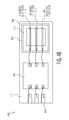
- FIGS. 4A and 4B show one example of a third electrochemical sensor 400 .
- the third electrochemical sensor 400 is in a two dimensional (2D) configuration with one electrode layer.
- An electrochemical cell is on a first die 402 and a potentiostat circuit with other read-out, buffering, data processing, memory and communications circuitry is on a second die 404 .
- the first die 402 includes an insulating substrate 406 .
- a porous layer 410 is deposited and patterned on top of the substrate 406 .
- a first, second and third top electrode 412 , 413 , 415 are deposited and patterned on the porous layer 410 .
- the first top electrode 412 is a counter electrode
- the second top electrode 413 is a working electrode
- the third top electrode 415 is a reference electrode.
- these top electrodes 412 , 413 , 415 could be assigned other functions or only two electrodes 412 , 413 could be used.
- the potentiostat and other circuitry formed on the second die 404 is fabricated using standard CMOS techniques and connected to the first die 402 and a lead frame 414 with bond wires 416 .
- the first and second dies 402 and 404 are then encapsulated 417 (e.g. over molded) leaving an opening 418 over the electrochemical sensor's top electrode 412 in the first die 402 .
- the opening 418 permits the target gas to contact the top electrodes 412 , 413 , 415 during operation of the electrochemical sensor 400 .
- the porous layer 410 is then partially or completely filled with an electrolyte.
- the electrolyte can in one example reach the porous layer 410 through the opening 418 in the top electrode 412 . In another example, the electrolyte reaches the porous layer 410 through a separate via provided elsewhere in the encapsulated sensor 400 package.
- the porous layer 410 with electrolyte is shown as 420 in FIG. 4A .
- the electrodes are in a planar arrangement and all electrodes are exposed to the same gases through the opening 418 .
- a potential difference is applied between the electrodes to drive the reaction.
- the sensor 400 current is not restricted by the electrolyte layer thickness and diffusion processes is governed by the much higher reaction rates for the reaction at the electrodes.
- electrodes 412 , 413 , 415 are instead placed on the substrate 406 underneath the porous layer 410 and the target gas molecules must diffuse through the porous layer with electrolyte 420 before reacting at the electrodes 412 , 413 , 415 .
- FIG. 5 shows one example of the first electrochemical sensor 100 having an additional sensor.
- the second die 102 includes the potentiostat and other circuitry; however, in this example embodiment, the second die 102 further includes additional sensing functionality such as a temperature sensor, a relative humidity sensor and/or other environmental sensors.
- the first and second dies 102 and 104 are then encapsulated 117 (e.g. over molded) leaving the opening 118 over the electrochemical sensor's top electrode 112 in the first die 102 , but also leaving a second opening 502 over the additional sensing functionality in the second die 104 .
- openings 118 , 502 permit various elements and/or molecules to interact with the electrochemical cell in the first die 102 and the additional sensing functionality in the second die 104 during operation of the electrochemical sensor 100 .
- the additional sensing functionality can be used to compensate for potential cross sensitivities of the electrochemical cell.
- Electrochemical cell may be sensitive e.g. to also relative humidity and temperature. In order to compensate for this effect a separate relative humidity sensor can be added.
- FIG. 6 shows one example of the first electrochemical sensor 100 having a filter 602 .
- the filter 602 is placed over the opening 118 which is above the electrochemical cell in the first die 102 .
- the filter 602 improves the electrochemical sensor's 100 target chemical selectivity by blocking one or more non-target substances (e.g. a CO sensor could include a filter to oxidize ethanol vapors which could cause similar electrode currents as the CO to be detected).
- the filter 602 is fixed above the opening 118 with anchoring structures 604 (e.g. pins, rings, adhesives).
- the anchoring structures 604 can be directly formed by and/or integrated into the encapsulation 117 .
- Individual filter 602 layers can be cut with a punch tool, applied by a pick and place machine, and glued or ultrasonically welded to the anchoring structures 604 .
- the filter 602 may also serve to protect the electrochemical cell in the first die 102 from contaminants and reduce evaporation of the electrolyte from the electrolyte matrix 110 .
- a filter 602 which minimizes evaporation includes a semi permeable membrane that allows passage of e.g. CO but not H 2 O.
- FIG. 7 shows one example of the first electrochemical sensor 100 having a reservoir. This example embodiment is similar to the embodiment shown in FIGS. 1A and 1B except that, in the first die 102 , the substrate 106 and the electrolyte matrix 110 have be extended in a lateral direction while the top and bottom electrodes 112 , 108 have retained their previous lateral dimensions.
- the first and second dies 102 and 104 are then encapsulated 117 leaving the opening 118 over the electrochemical sensor's top electrode 112 and adding a second opening 702 over the electrolyte matrix 110 .
- the electrolyte matrix 110 is then partially or completely filled with an electrolyte 704 .
- the electrolyte 704 is also is added into the second opening 702 , thereby forming a reservoir of the electrolyte 704 .
- This reservoir of electrolyte further buffers potential evaporation or uptake of water by the electrolyte matrix 110 .
- a cover 706 can be added over the second opening 702 to further counteract any effects of evaporation on the electrolyte 704 in the reservoir.
- FIG. 8 shows one example of a fourth electrochemical sensor 800 having a stacked configuration.
- the fourth electrochemical sensor 800 is in a three dimensional (3D) configuration with two electrode layers.
- An electronic circuit with potentiostat, read-out, buffering, data processing, memory and communications circuitry, and an electrochemical cell are stacked together within a die 802 .
- the die 802 includes a planarized passivation stack (not shown) on top.
- the passivation stack serves as barrier layer from an electrolyte filled porous layer within the electrochemical cell on top of the die 802 . Additional layers (e.g. metal, platinum, silicon nitride) can be deposited on top of this passivation stack to augment the barrier layer.
- the die 802 includes the electronic circuit for the potentiostat and other electronics onto which a set of output electrodes 804 are patterned.
- a bottom electrode 808 is deposited and patterned on the die 802 and in contact with one of the set of output electrodes 804 .
- the bottom electrode 808 in one example embodiment is a counter electrode, but in other embodiments could be either the working electrode or a reference electrode.
- a porous layer 810 is deposited and patterned on top of the bottom electrode 808 and in contact with another one of the set of output electrodes 804 .
- a via 811 e.g. tungsten, preferably same material as top electrode otherwise risk of electrochemical reactions/corrosion
- a top electrode 812 is deposited and patterned on the porous layer 810 and in electrical contact with the via 811 .
- the top electrode 812 in one example embodiment is a working electrode, but in other embodiments could be either a counter electrode or a reference electrode.
- the die 802 is connected to a lead frame 814 with bond wires 816 .
- the die 802 is then encapsulated 817 (e.g. over molded) leaving an opening 818 over the electrochemical sensor's top electrode 812 in the die 802 .
- the opening 818 permits the target gas to contact the top electrode 812 first during operation of the electrochemical sensor 800 .
- the porous layer 810 is then partially or completely filled with an electrolyte.
- the electrolyte can in one example reach the porous layer 810 through the opening 818 and a via (not shown) in the top electrode 812 .
- the electrolyte reaches the porous layer 810 through a separate via provided elsewhere in the encapsulated sensor 800 package.
- the porous layer 810 with electrolyte is shown as 820 in FIG. 8 .
- the porous layer can be porous enough so that the liquid electrolyte will penetrate through the electrode material film.
- the via 811 can be omitted by connecting the top electrode 812 to the lead frame 814 with a separate bond wire 816 .
- FIG. 9 is a first example of a method 900 for manufacturing an electrochemical sensor for sensing a target substance.
- the method 900 begins in block 902 , by fabricating a electrolyte matrix having a porous structure.
- block 904 coupling a working electrode to the electrolyte matrix at a first location is performed.
- block 906 coupling a counter electrode to the electrolyte matrix at a second location occurs.
- an electrolyte is added to the porous structure.
- an electrical circuit is coupled to the working electrode and the counter electrode, wherein the electrical circuit is capable of generating an output signal in response to an electrical current which flows between the working electrode and the counter electrode in response to a presence of the target substance. While the order in which these steps are implemented can be changed, the proposed sequence aims at manufacturing electrochemical cell first independently before connecting to read out electronics. Alternately steps 908 and 910 can be switched during wafer processing.
- Example embodiments of the material discussed in this specification can be implemented in whole or in part through network, computer, or data based devices and/or services. These may include cloud, internet, intranet, mobile, desktop, processor, look-up table, microcontroller, consumer equipment, infrastructure, or other enabling devices and services. As may be used herein and in the claims, the following non-exclusive definitions are provided.
- the method steps described above are implemented as functional and software instructions embodied as a set of executable instructions which are effected on a computer which is programmed with and controlled by said executable instructions. Such instructions are loaded for execution on a processor (such as one or more CPUs).
- the processor includes microprocessors, microcontrollers, processor modules or subsystems (including one or more microprocessors or microcontrollers), or other control or computing devices.
- a processor can refer to a single component or to plural components.
- one or more blocks or steps discussed herein are automated.
- apparatus, systems, and methods occur automatically.
- automated or automatically mean controlled operation of an apparatus, system, and/or process using computers and/or mechanical/electrical devices without the necessity of human intervention, observation, effort and/or decision.
- the methods illustrated herein and data and instructions associated therewith are stored in respective storage devices, which are implemented as one or more non-transient computer-readable or computer-usable storage media or mediums.
- the non-transient computer-usable media or mediums as defined herein excludes signals, but such media or mediums may be capable of receiving and processing information from signals and/or other transient mediums.
- the storage media include different forms of memory including semiconductor memory devices such as DRAM, or SRAM, Erasable and Programmable Read-Only Memories (EPROMs), Electrically Erasable and Programmable Read-Only Memories (EEPROMs) and flash memories; magnetic disks such as fixed, floppy and removable disks; other magnetic media including tape; and optical media such as Compact Disks (CDs) or Digital Versatile Disks (DVDs).
- semiconductor memory devices such as DRAM, or SRAM, Erasable and Programmable Read-Only Memories (EPROMs), Electrically Erasable and Programmable Read-Only Memories (EEPROMs) and flash memories
- magnetic disks such as fixed, floppy and removable disks
- other magnetic media including tape and optical media such as Compact Disks (CDs) or Digital Versatile Disks (DVDs).
- CDs Compact Disks
- DVDs Digital Versatile Disks
Abstract
Description
-
- At sensing (working) electrode: CO+H2O→CO2+2H++2e−
- At counter electrode: ½O2+2H++2e−→H2O
- Overall reaction is: CO+½O2→CO2
-
- Absorption of the target chemical at the electrolyte interface;
- Transport of [CO] and [O2] by diffusion; and
- Chemical molecules adsorbed at the electrode surface.
-
- Where: “n” is the number of electrons involved in the reaction, F Faraday's constant, A the electrode surface area, DCO the diffusion constant of CO in the electrolyte, cCO the concentration of CO molecules at the air-electrolyte interface and δ the thickness of the electrolyte. DCO, kH and csolvent are material constants.
Claims (16)
Priority Applications (3)
| Application Number | Priority Date | Filing Date | Title |
|---|---|---|---|
| US14/192,648 US9513247B2 (en) | 2014-02-27 | 2014-02-27 | Electrochemical sensor |
| EP15151261.3A EP2913667B1 (en) | 2014-02-27 | 2015-01-15 | Electrochemical sensor |
| CN201510082174.1A CN104880499B (en) | 2014-02-27 | 2015-02-15 | Electrochemical sensor |
Applications Claiming Priority (1)
| Application Number | Priority Date | Filing Date | Title |
|---|---|---|---|
| US14/192,648 US9513247B2 (en) | 2014-02-27 | 2014-02-27 | Electrochemical sensor |
Publications (2)
| Publication Number | Publication Date |
|---|---|
| US20150241375A1 US20150241375A1 (en) | 2015-08-27 |
| US9513247B2 true US9513247B2 (en) | 2016-12-06 |
Family
ID=52347194
Family Applications (1)
| Application Number | Title | Priority Date | Filing Date |
|---|---|---|---|
| US14/192,648 Active 2034-11-13 US9513247B2 (en) | 2014-02-27 | 2014-02-27 | Electrochemical sensor |
Country Status (3)
| Country | Link |
|---|---|
| US (1) | US9513247B2 (en) |
| EP (1) | EP2913667B1 (en) |
| CN (1) | CN104880499B (en) |
Families Citing this family (9)
| Publication number | Priority date | Publication date | Assignee | Title |
|---|---|---|---|---|
| WO2017123205A1 (en) | 2016-01-12 | 2017-07-20 | Honeywell International Inc. | Electrochemical sensor |
| US20170336343A1 (en) * | 2016-05-19 | 2017-11-23 | InSyte Systems | Integrated sensing device for detecting gasses |
| EP3346267B1 (en) * | 2017-01-10 | 2021-09-01 | Sensirion AG | Sensor device for detecting a permanent gas |
| US10756745B2 (en) | 2017-01-27 | 2020-08-25 | Verily Life Sciences Llc | Electrical circuit for biasing or measuring current from a sensor |
| US10732141B2 (en) | 2017-02-15 | 2020-08-04 | InSyte Systems | Electrochemical gas sensor system with improved accuracy and speed |
| US11567031B2 (en) * | 2017-09-08 | 2023-01-31 | Oakland University | Selective real-time gas sensing |
| US11054383B2 (en) | 2018-01-22 | 2021-07-06 | InSyte Systems, Inc. | Chip-scale sensing device for low density material |
| JP7201178B2 (en) * | 2019-06-13 | 2023-01-10 | 日本航空電子工業株式会社 | Electrochemical measurement method for catalytic reaction product, electrochemical measurement device, and transducer |
| CN110530952B (en) * | 2019-08-19 | 2022-05-17 | 广州钰芯传感科技有限公司 | Card-inserting type electrochemical gas sensor module and packaging method thereof |
Citations (22)
| Publication number | Priority date | Publication date | Assignee | Title |
|---|---|---|---|---|
| US3616416A (en) | 1969-07-02 | 1971-10-26 | Hydronautics | Oxygen detector for analysis of oxygen in gaseous streams including an internal humidifier |
| EP0125807A2 (en) | 1983-04-18 | 1984-11-21 | Biospecific Technologies, Inc. | pH and CO2 sensing device |
| US4913792A (en) | 1987-07-28 | 1990-04-03 | Daikin Industries, Ltd. | Flammable-gas sensor |
| EP0432757A2 (en) | 1989-12-14 | 1991-06-19 | Hitachi, Ltd. | Planar oxygen sensor |
| EP0514873A1 (en) | 1991-05-24 | 1992-11-25 | Honda Giken Kogyo Kabushiki Kaisha | Heater type hybrid integrated circuit |
| US5215643A (en) | 1988-02-24 | 1993-06-01 | Matsushita Electric Works, Ltd. | Electrochemical gas sensor |
| EP0625704A2 (en) | 1993-04-09 | 1994-11-23 | Ciba-Geigy Ag | Extended use planar sensors |
| US6376124B1 (en) * | 1996-12-07 | 2002-04-23 | Central Research Laboratories, Limited | Electrochemical cell |
| US20030121781A1 (en) | 1999-11-19 | 2003-07-03 | Prohaska Otto J. | Hybrid film type sensor |
| US20040026246A1 (en) * | 2000-07-27 | 2004-02-12 | John Chapples | Gas sensors |
| US20040026268A1 (en) | 2000-12-07 | 2004-02-12 | Masao Maki | Gas sensor and detection method and device for gas.concentration |
| DE10323858A1 (en) | 2003-05-26 | 2004-12-30 | Infineon Technologies Ag | Biosensor to detect particles in an analyte, e.g. for high throughput screening, has a substrate with surface electrodes and a gold compartmenting unit to take the catch molecules |
| US20080128285A1 (en) | 2006-12-04 | 2008-06-05 | Electronics And Telecommunications Research Institute | Electrochemical gas sensor chip and method of manufacturing the same |
| US20100133120A1 (en) | 2007-03-15 | 2010-06-03 | Anaxsys Technology Ltd | Electrochemical Sensor |
| US20110226619A1 (en) | 2008-12-01 | 2011-09-22 | Msa Auer Gmbh | Electrochemical Gas Sensors with Ionic Liquid Electrolyte Systems |
| US20110253534A1 (en) | 2008-12-01 | 2011-10-20 | Msa Auer Gmbh | Electrochemical Gas Sensor with an Ionic Liquid Electrolyte System Including at Least One Monoalkylammonium, Dialkylammonium, or Trialkylammonium Cation |
| US20120036921A1 (en) | 2009-04-15 | 2012-02-16 | Neroxis Sa | Amperometric electrochemical sensor and method for manufacturing same |
| US20120098075A1 (en) | 2009-10-23 | 2012-04-26 | Alberto Lamagna | Integrated electronic device for detecting molecules and method of manufacture thereof |
| US20130091924A1 (en) * | 2011-10-14 | 2013-04-18 | Towner Bennett Scheffler | Sensor interrogation |
| US20130144131A1 (en) | 2010-06-10 | 2013-06-06 | The Regents Of The University Of California | Textile-based printable electrodes for electrochemical sensing |
| EP2759832A1 (en) | 2013-01-23 | 2014-07-30 | Nxp B.V. | Electrochemical sensor device |
| US8852513B1 (en) | 2011-09-30 | 2014-10-07 | Silicon Laboratories Inc. | Systems and methods for packaging integrated circuit gas sensor systems |
-
2014
- 2014-02-27 US US14/192,648 patent/US9513247B2/en active Active
-
2015
- 2015-01-15 EP EP15151261.3A patent/EP2913667B1/en active Active
- 2015-02-15 CN CN201510082174.1A patent/CN104880499B/en active Active
Patent Citations (22)
| Publication number | Priority date | Publication date | Assignee | Title |
|---|---|---|---|---|
| US3616416A (en) | 1969-07-02 | 1971-10-26 | Hydronautics | Oxygen detector for analysis of oxygen in gaseous streams including an internal humidifier |
| EP0125807A2 (en) | 1983-04-18 | 1984-11-21 | Biospecific Technologies, Inc. | pH and CO2 sensing device |
| US4913792A (en) | 1987-07-28 | 1990-04-03 | Daikin Industries, Ltd. | Flammable-gas sensor |
| US5215643A (en) | 1988-02-24 | 1993-06-01 | Matsushita Electric Works, Ltd. | Electrochemical gas sensor |
| EP0432757A2 (en) | 1989-12-14 | 1991-06-19 | Hitachi, Ltd. | Planar oxygen sensor |
| EP0514873A1 (en) | 1991-05-24 | 1992-11-25 | Honda Giken Kogyo Kabushiki Kaisha | Heater type hybrid integrated circuit |
| EP0625704A2 (en) | 1993-04-09 | 1994-11-23 | Ciba-Geigy Ag | Extended use planar sensors |
| US6376124B1 (en) * | 1996-12-07 | 2002-04-23 | Central Research Laboratories, Limited | Electrochemical cell |
| US20030121781A1 (en) | 1999-11-19 | 2003-07-03 | Prohaska Otto J. | Hybrid film type sensor |
| US20040026246A1 (en) * | 2000-07-27 | 2004-02-12 | John Chapples | Gas sensors |
| US20040026268A1 (en) | 2000-12-07 | 2004-02-12 | Masao Maki | Gas sensor and detection method and device for gas.concentration |
| DE10323858A1 (en) | 2003-05-26 | 2004-12-30 | Infineon Technologies Ag | Biosensor to detect particles in an analyte, e.g. for high throughput screening, has a substrate with surface electrodes and a gold compartmenting unit to take the catch molecules |
| US20080128285A1 (en) | 2006-12-04 | 2008-06-05 | Electronics And Telecommunications Research Institute | Electrochemical gas sensor chip and method of manufacturing the same |
| US20100133120A1 (en) | 2007-03-15 | 2010-06-03 | Anaxsys Technology Ltd | Electrochemical Sensor |
| US20110226619A1 (en) | 2008-12-01 | 2011-09-22 | Msa Auer Gmbh | Electrochemical Gas Sensors with Ionic Liquid Electrolyte Systems |
| US20110253534A1 (en) | 2008-12-01 | 2011-10-20 | Msa Auer Gmbh | Electrochemical Gas Sensor with an Ionic Liquid Electrolyte System Including at Least One Monoalkylammonium, Dialkylammonium, or Trialkylammonium Cation |
| US20120036921A1 (en) | 2009-04-15 | 2012-02-16 | Neroxis Sa | Amperometric electrochemical sensor and method for manufacturing same |
| US20120098075A1 (en) | 2009-10-23 | 2012-04-26 | Alberto Lamagna | Integrated electronic device for detecting molecules and method of manufacture thereof |
| US20130144131A1 (en) | 2010-06-10 | 2013-06-06 | The Regents Of The University Of California | Textile-based printable electrodes for electrochemical sensing |
| US8852513B1 (en) | 2011-09-30 | 2014-10-07 | Silicon Laboratories Inc. | Systems and methods for packaging integrated circuit gas sensor systems |
| US20130091924A1 (en) * | 2011-10-14 | 2013-04-18 | Towner Bennett Scheffler | Sensor interrogation |
| EP2759832A1 (en) | 2013-01-23 | 2014-07-30 | Nxp B.V. | Electrochemical sensor device |
Non-Patent Citations (17)
| Title |
|---|
| Alphasense Limited; "Alphasense Application Note AAN 105-3 Desigining a Potentiostatic Circuit"; Great Notley, Essex, UK; 5 pages (Mar. 2009). |
| Boutet et al., "Low power CMOS potentiostat for three electrodes amperometric chemical sensor", Faible Tension Faible Consommation (FTFC), 2011, IEEE, pp. 15-18, May 30, 2011. |
| Currie et al., "Micromachined Thin Film Solid State Electrochemical CO2, NO 2, and SO2 Gas Sensors" Sensors and Actuators B 59, pp. 235-241, 1999. |
| DIN EN 50291-1 (VDE 0400-34-1); First Pages; 14 pages w/translation) (Nov. 2009). |
| Draeger; "XXS CO Sensor Specifications"; retrieved from the internet Feb. 25, 2014 http://www.draeger.com/sites/assets/PublishingImages/Products/cin-draegersensor-xxs/Master/9094331-Sensoren-PI-EN-111113-fin.pdf ; 4 pages. |
| DropSens; "Customised SPEs"; retreived from the internet Feb. 25, 2014 http://www.dropsens.com/en/pdfs-productos/new-brochures/customised-spes.pdf; 1 page. |
| Dubbe, A. "Fundamentals of solid state ionic micro gas sensors", Sensors and Actuators,vol. 88, No. 2, pp. 138-148, Jan. 15, 2003. |
| Extended European Search Report for Application No. 13152411.8, dated Apr. 17, 2013,10 pages. |
| Gardner et al., CMOS Interfacing for Integrated Gas Sensors: A Review, (IEEE Sensors Journal, vol. 10, No. 12, Dec. 2010). |
| Microsens; "Microsens Amperometric Sensor"; Sensor Description, retrieved from the internet Feb. 25, 2014 http://www.microsens.ch/products/pdf/Amperometric-Sensor.pdf; 2 pages. |
| Tan et al., "A 1.8V 11 W CMOS Smart Humidity Sensor for RFID Sensing Application" IEEE Asian Solid State Circuits Conference, Nov. 14-16, 2011, Jeju, Korea, pp. 105-108. |
| UL, "Carbon Monoxide Alarm Considerations for Code Authorities", The Code Authority newsletter, Issue 3, 2009. |
| Underwriters Laboratories Inc; "UL2034, Single and Multiple Station Carbon Monoxide Alarms-Table of Contents"; 14 pages (Feb. 20, 2009). |
| Wollenstein et al., "A Novel Single Chip Thin Film Metal Oxide Array", Sensors and Actuators B 93, pp. 350-355, 2003. |
| Wollenstein et al., "Material Properties and the influence of metallic catalysts at the surface of highly dense SnO2 films" Sensors and Actuators B, vol. 70 (2000), pp. 196-202. |
| Wollenstein et al., "Preparation, morphology and gas-sensing behavior of Cr2-xTixO3+z thin-films on standard silicon wafers" IEEE Sens. J., vol. 2 (2002), pp. 403-408. |
| Yamazaki et al., "Design and Fabrication of Complementary Metal-Oxide-Semiconductor Sensor Chip for Electrochemical Measurement", Japanese Journal of applied Physics, vol. 49, No. 4, p. 04DL11, Apr. 1, 2010. |
Also Published As
| Publication number | Publication date |
|---|---|
| US20150241375A1 (en) | 2015-08-27 |
| EP2913667B1 (en) | 2023-03-01 |
| EP2913667A1 (en) | 2015-09-02 |
| CN104880499A (en) | 2015-09-02 |
| CN104880499B (en) | 2017-12-12 |
Similar Documents
| Publication | Publication Date | Title |
|---|---|---|
| US9513247B2 (en) | Electrochemical sensor | |
| US4874500A (en) | Microelectrochemical sensor and sensor array | |
| US10429335B2 (en) | Integrated gas sensor device, in particular for detecting carbon monoxide (CO) | |
| Huang et al. | Toward membrane-free amperometric gas sensors: A microelectrode array approach | |
| US8535499B2 (en) | Microfabricated liquid-junction reference electrode | |
| US8795484B2 (en) | Printed gas sensor | |
| US10895548B2 (en) | Reference electrode with a pore membrane | |
| US20050072690A1 (en) | Ion exchange membranes and dissolved gas sensors | |
| US20110100810A1 (en) | Chip integrated ion sensor | |
| US20230137889A1 (en) | Electrochemical sensor with opening between solid elements | |
| CN103940862B (en) | Electrochemical sensor device | |
| JP2014528590A (en) | Sensor and sensor manufacturing method | |
| KR101330221B1 (en) | Sensors for detecting ion concentration using CNT and methods manufacturing the same | |
| CN109716121B (en) | Electrochemical gas sensor with multiple gas inlets | |
| CN112268942A (en) | Micro-nano sensing device, preparation method thereof and pH value detection method | |
| JP2009002802A (en) | Water sensor and dew condensation sensor | |
| EP2827141A1 (en) | Device and method for electrochemical gas sensing | |
| US10082391B2 (en) | Rotational sensors including ionic liquids and methods of making and using the same | |
| CN114829918A (en) | Sensor with solid layered structure and method for manufacturing the same | |
| US8901433B2 (en) | Individually addressable band electrode arrays and methods to prepare the same | |
| JPS6070348A (en) | Fet chemical sensor | |
| JPH02205768A (en) | Electrochemical sensor |
Legal Events
| Date | Code | Title | Description |
|---|---|---|---|
| AS | Assignment |
Owner name: NXP, B.V., NETHERLANDS Free format text: ASSIGNMENT OF ASSIGNORS INTEREST;ASSIGNORS:MERZ, MATTHIAS;SOCCOL, DIMITRI;REEL/FRAME:032318/0079 Effective date: 20140226 |
|
| AS | Assignment |
Owner name: AMS INTERNATIONAL AG, SWITZERLAND Free format text: ASSIGNMENT OF ASSIGNORS INTEREST;ASSIGNOR:NXP B.V.;REEL/FRAME:036015/0613 Effective date: 20150608 |
|
| AS | Assignment |
Owner name: MORGAN STANLEY SENIOR FUNDING, INC., MARYLAND Free format text: SECURITY AGREEMENT SUPPLEMENT;ASSIGNOR:NXP B.V.;REEL/FRAME:038017/0058 Effective date: 20160218 |
|
| AS | Assignment |
Owner name: MORGAN STANLEY SENIOR FUNDING, INC., MARYLAND Free format text: CORRECTIVE ASSIGNMENT TO CORRECT THE REMOVE APPLICATION 12092129 PREVIOUSLY RECORDED ON REEL 038017 FRAME 0058. ASSIGNOR(S) HEREBY CONFIRMS THE SECURITY AGREEMENT SUPPLEMENT;ASSIGNOR:NXP B.V.;REEL/FRAME:039361/0212 Effective date: 20160218 |
|
| AS | Assignment |
Owner name: NXP B.V., NETHERLANDS Free format text: PATENT RELEASE;ASSIGNOR:MORGAN STANLEY SENIOR FUNDING, INC.;REEL/FRAME:039707/0471 Effective date: 20160805 |
|
| STCF | Information on status: patent grant |
Free format text: PATENTED CASE |
|
| AS | Assignment |
Owner name: MORGAN STANLEY SENIOR FUNDING, INC., MARYLAND Free format text: CORRECTIVE ASSIGNMENT TO CORRECT THE REMOVE APPLICATION 12681366 PREVIOUSLY RECORDED ON REEL 039361 FRAME 0212. ASSIGNOR(S) HEREBY CONFIRMS THE SECURITY AGREEMENT SUPPLEMENT;ASSIGNOR:NXP B.V.;REEL/FRAME:042762/0145 Effective date: 20160218 Owner name: MORGAN STANLEY SENIOR FUNDING, INC., MARYLAND Free format text: CORRECTIVE ASSIGNMENT TO CORRECT THE REMOVE APPLICATION 12681366 PREVIOUSLY RECORDED ON REEL 038017 FRAME 0058. ASSIGNOR(S) HEREBY CONFIRMS THE SECURITY AGREEMENT SUPPLEMENT;ASSIGNOR:NXP B.V.;REEL/FRAME:042985/0001 Effective date: 20160218 |
|
| AS | Assignment |
Owner name: NXP B.V., NETHERLANDS Free format text: RELEASE BY SECURED PARTY;ASSIGNOR:MORGAN STANLEY SENIOR FUNDING, INC.;REEL/FRAME:050745/0001 Effective date: 20190903 |
|
| AS | Assignment |
Owner name: MORGAN STANLEY SENIOR FUNDING, INC., MARYLAND Free format text: CORRECTIVE ASSIGNMENT TO CORRECT THE REMOVE APPLICATION 12298143 PREVIOUSLY RECORDED ON REEL 039361 FRAME 0212. ASSIGNOR(S) HEREBY CONFIRMS THE SECURITY AGREEMENT SUPPLEMENT;ASSIGNOR:NXP B.V.;REEL/FRAME:051029/0387 Effective date: 20160218 Owner name: MORGAN STANLEY SENIOR FUNDING, INC., MARYLAND Free format text: CORRECTIVE ASSIGNMENT TO CORRECT THE REMOVE APPLICATION 12298143 PREVIOUSLY RECORDED ON REEL 042985 FRAME 0001. ASSIGNOR(S) HEREBY CONFIRMS THE SECURITY AGREEMENT SUPPLEMENT;ASSIGNOR:NXP B.V.;REEL/FRAME:051029/0001 Effective date: 20160218 Owner name: MORGAN STANLEY SENIOR FUNDING, INC., MARYLAND Free format text: CORRECTIVE ASSIGNMENT TO CORRECT THE REMOVE APPLICATION 12298143 PREVIOUSLY RECORDED ON REEL 042762 FRAME 0145. ASSIGNOR(S) HEREBY CONFIRMS THE SECURITY AGREEMENT SUPPLEMENT;ASSIGNOR:NXP B.V.;REEL/FRAME:051145/0184 Effective date: 20160218 Owner name: MORGAN STANLEY SENIOR FUNDING, INC., MARYLAND Free format text: CORRECTIVE ASSIGNMENT TO CORRECT THE REMOVE APPLICATION12298143 PREVIOUSLY RECORDED ON REEL 039361 FRAME 0212. ASSIGNOR(S) HEREBY CONFIRMS THE SECURITY AGREEMENT SUPPLEMENT;ASSIGNOR:NXP B.V.;REEL/FRAME:051029/0387 Effective date: 20160218 Owner name: MORGAN STANLEY SENIOR FUNDING, INC., MARYLAND Free format text: CORRECTIVE ASSIGNMENT TO CORRECT THE REMOVE APPLICATION 12298143 PREVIOUSLY RECORDED ON REEL 038017 FRAME 0058. ASSIGNOR(S) HEREBY CONFIRMS THE SECURITY AGREEMENT SUPPLEMENT;ASSIGNOR:NXP B.V.;REEL/FRAME:051030/0001 Effective date: 20160218 Owner name: MORGAN STANLEY SENIOR FUNDING, INC., MARYLAND Free format text: CORRECTIVE ASSIGNMENT TO CORRECT THE REMOVE APPLICATION12298143 PREVIOUSLY RECORDED ON REEL 042985 FRAME 0001. ASSIGNOR(S) HEREBY CONFIRMS THE SECURITY AGREEMENT SUPPLEMENT;ASSIGNOR:NXP B.V.;REEL/FRAME:051029/0001 Effective date: 20160218 Owner name: MORGAN STANLEY SENIOR FUNDING, INC., MARYLAND Free format text: CORRECTIVE ASSIGNMENT TO CORRECT THE REMOVE APPLICATION12298143 PREVIOUSLY RECORDED ON REEL 042762 FRAME 0145. ASSIGNOR(S) HEREBY CONFIRMS THE SECURITY AGREEMENT SUPPLEMENT;ASSIGNOR:NXP B.V.;REEL/FRAME:051145/0184 Effective date: 20160218 |
|
| AS | Assignment |
Owner name: SCIOSENSE B.V., NETHERLANDS Free format text: ASSIGNMENT OF ASSIGNORS INTEREST;ASSIGNORS:AMS AG;AMS INTERNATIONAL AG;AMS SENSORS UK LIMITED;AND OTHERS;REEL/FRAME:052769/0820 Effective date: 20200113 |
|
| MAFP | Maintenance fee payment |
Free format text: PAYMENT OF MAINTENANCE FEE, 4TH YEAR, LARGE ENTITY (ORIGINAL EVENT CODE: M1551); ENTITY STATUS OF PATENT OWNER: LARGE ENTITY Year of fee payment: 4 |