US9517032B2 - Sensor over-mold shape - Google Patents
Sensor over-mold shape Download PDFInfo
- Publication number
- US9517032B2 US9517032B2 US13/362,371 US201213362371A US9517032B2 US 9517032 B2 US9517032 B2 US 9517032B2 US 201213362371 A US201213362371 A US 201213362371A US 9517032 B2 US9517032 B2 US 9517032B2
- Authority
- US
- United States
- Prior art keywords
- outer layer
- thickness
- along
- inner shell
- wall
- Prior art date
- Legal status (The legal status is an assumption and is not a legal conclusion. Google has not performed a legal analysis and makes no representation as to the accuracy of the status listed.)
- Active, expires
Links
Images


Classifications
-
- A—HUMAN NECESSITIES
- A61—MEDICAL OR VETERINARY SCIENCE; HYGIENE
- A61B—DIAGNOSIS; SURGERY; IDENTIFICATION
- A61B5/00—Measuring for diagnostic purposes; Identification of persons
- A61B5/68—Arrangements of detecting, measuring or recording means, e.g. sensors, in relation to patient
- A61B5/6846—Arrangements of detecting, measuring or recording means, e.g. sensors, in relation to patient specially adapted to be brought in contact with an internal body part, i.e. invasive
- A61B5/6847—Arrangements of detecting, measuring or recording means, e.g. sensors, in relation to patient specially adapted to be brought in contact with an internal body part, i.e. invasive mounted on an invasive device
- A61B5/6861—Capsules, e.g. for swallowing or implanting
-
- A—HUMAN NECESSITIES
- A61—MEDICAL OR VETERINARY SCIENCE; HYGIENE
- A61B—DIAGNOSIS; SURGERY; IDENTIFICATION
- A61B5/00—Measuring for diagnostic purposes; Identification of persons
- A61B5/02—Detecting, measuring or recording pulse, heart rate, blood pressure or blood flow; Combined pulse/heart-rate/blood pressure determination; Evaluating a cardiovascular condition not otherwise provided for, e.g. using combinations of techniques provided for in this group with electrocardiography or electroauscultation; Heart catheters for measuring blood pressure
- A61B5/021—Measuring pressure in heart or blood vessels
- A61B5/0215—Measuring pressure in heart or blood vessels by means inserted into the body
-
- A—HUMAN NECESSITIES
- A61—MEDICAL OR VETERINARY SCIENCE; HYGIENE
- A61B—DIAGNOSIS; SURGERY; IDENTIFICATION
- A61B2560/00—Constructional details of operational features of apparatus; Accessories for medical measuring apparatus
- A61B2560/04—Constructional details of apparatus
- A61B2560/0406—Constructional details of apparatus specially shaped apparatus housings
-
- A—HUMAN NECESSITIES
- A61—MEDICAL OR VETERINARY SCIENCE; HYGIENE
- A61B—DIAGNOSIS; SURGERY; IDENTIFICATION
- A61B2562/00—Details of sensors; Constructional details of sensor housings or probes; Accessories for sensors
- A61B2562/02—Details of sensors specially adapted for in-vivo measurements
- A61B2562/0247—Pressure sensors
-
- A—HUMAN NECESSITIES
- A61—MEDICAL OR VETERINARY SCIENCE; HYGIENE
- A61B—DIAGNOSIS; SURGERY; IDENTIFICATION
- A61B2562/00—Details of sensors; Constructional details of sensor housings or probes; Accessories for sensors
- A61B2562/16—Details of sensor housings or probes; Details of structural supports for sensors
- A61B2562/162—Capsule shaped sensor housings, e.g. for swallowing or implantation
-
- A—HUMAN NECESSITIES
- A61—MEDICAL OR VETERINARY SCIENCE; HYGIENE
- A61B—DIAGNOSIS; SURGERY; IDENTIFICATION
- A61B2562/00—Details of sensors; Constructional details of sensor housings or probes; Accessories for sensors
- A61B2562/18—Shielding or protection of sensors from environmental influences, e.g. protection from mechanical damage
-
- A—HUMAN NECESSITIES
- A61—MEDICAL OR VETERINARY SCIENCE; HYGIENE
- A61B—DIAGNOSIS; SURGERY; IDENTIFICATION
- A61B5/00—Measuring for diagnostic purposes; Identification of persons
- A61B5/68—Arrangements of detecting, measuring or recording means, e.g. sensors, in relation to patient
- A61B5/6846—Arrangements of detecting, measuring or recording means, e.g. sensors, in relation to patient specially adapted to be brought in contact with an internal body part, i.e. invasive
- A61B5/6867—Arrangements of detecting, measuring or recording means, e.g. sensors, in relation to patient specially adapted to be brought in contact with an internal body part, i.e. invasive specially adapted to be attached or implanted in a specific body part
- A61B5/6876—Blood vessel
-
- G—PHYSICS
- G01—MEASURING; TESTING
- G01L—MEASURING FORCE, STRESS, TORQUE, WORK, MECHANICAL POWER, MECHANICAL EFFICIENCY, OR FLUID PRESSURE
- G01L19/00—Details of, or accessories for, apparatus for measuring steady or quasi-steady pressure of a fluent medium insofar as such details or accessories are not special to particular types of pressure gauges
- G01L19/14—Housings
- G01L19/145—Housings with stress relieving means
- G01L19/146—Housings with stress relieving means using flexible element between the transducer and the support
Abstract
An implantable sensor module and medical device includes a housing having an inner shell having a thickness extending between an inner wall and an outer wall and an outer layer, wherein the inner shell and the outer layer form a substantially flat portion. A shoulder extends adjacent to a diaphragm to extend the outer layer laterally away from a central medial line extending between edges of the diaphragm. A recess portion is formed between the diaphragm and an inner side of the outer layer, and an over-fill channel is formed by the outer layer extending through the outer layer from an opening formed at the outer wall to an opening formed along the inner side of the outer layer extending along the substantially flat portion.
Description
Cross-reference is hereby made to the commonly-assigned related U.S. application Ser. No. 13/362,270, entitled “SENSOR OVER-MOLD SHAPE,” to Flo et al., and U.S. application Ser. No. 13/362,305, entitled “SENSOR OVER-MOLD SHAPE,” to Flo et al., both filed concurrently herewith and incorporated herein by reference in its entirety.
The disclosure relates generally to medical devices and, in particular, to a housing of an implantable medical sensor module that includes a diaphragm.
Implantable medical sensors are used for sensing physiological signals in a patient for use in diagnosing a disease state or managing patient therapies. Among examples of implantable sensors are pressure sensors, flow sensors, acoustical sensors, and optical sensors. A pressure sensor positioned in the heart or in a blood vessel is highly useful in monitoring cardiovascular conditions, such as heart failure, hypertension, arrhythmias or other conditions. For example, a capacitive pressure sensor includes one capacitor electrode along a diaphragm and a second capacitor electrode substantially parallel to and held a few micrometers from the electrode of the diaphragm. An “air gap” provides insulation between the two parallel electrodes. As the blood pressure changes, the diaphragm flexes closer to or further away from the second electrode, resulting in a change in capacitance. The capacitance can be measured in many ways and can be converted to pressure using a calibration algorithm.
Some sensors can produce a baseline signal that drifts over time or presents a baseline offset. The causes of drift or offset can vary and lead to erroneous measurements determined from the sensor signal, particularly for calibrated sensors such as a calibrated pressure sensor. Accordingly, sensor designs are needed that reduce the potential for error in chronically implanted sensors.
In the following description, references are made to illustrative embodiments. It is understood that other embodiments may be utilized without departing from the scope of the disclosure.
In other embodiments, as shown in FIG. 1B , a sensor module 10′ may be carried by an elongated flexible medical lead body 8. Sensor module 10′ may correspond generally to sensor module 10 shown in FIG. 1A with the exception of being coupled to the lead body 8 and may be configured for wireless or wired signal transmission to an associated medical device. Elongated lead body 8 may additionally carry other sensors or electrodes and typically includes elongated electrical conductors extending between sensors and/or electrodes carried by the lead body 8 and a proximal electrical connector assembly (not shown). The connector assembly is adapted for connection to a medical device such as a pacemaker, cardioverter/defibrillator, neurostimulator, monitoring device or the like to provide electrical connection between sensors and/or electrodes carried by the lead body 8 and the associated medical device.
Examples of implantable devices that sensor module 10 may be used with, in either a wireless configuration as shown in FIG. 1A or a lead-based configuration as shown in FIG. 1B , are generally disclosed in commonly-assigned U.S. Publication No. 2010/0076819 (Kornet), U.S. Pat. No. 5,540,731 (Testerman), U.S. Pat. No. 7,367,951 (Bennett), U.S. Pat. No. 6,580,946 (Struble), and U.S. Publication No. 2009/0299429 (Mayotte), all of which references are incorporated herein by reference in their entirety. A capacitive pressure sensor is generally disclosed in commonly-assigned U.S. Pat. No. 5,535,752 (Halperin), hereby incorporated herein by reference in its entirety.
In other embodiments, hybrid circuit 24 includes any signal transducer responsive to movement, force or pressure applied to diaphragm 22 which may include fluid pressure, sound waves, or other mechanical forces. For example, a piezoresistive sensor, acoustical sensor, optical sensor or any other sensor that includes a diaphragm, which may or may not require an insulative layer beneath the diaphragm, may benefit from the housing shapes and designs disclosed herein.
The body's foreign body response will naturally result in tissue encapsulation of sensor 10 when it is implanted chronically. The tissue encapsulation or “scar” is generally fibrous tissue and can alter the response of the implantable sensor 10 over time. As the scar tissue ages it can shrink or contract. The inventors of the present application have discovered that shrinking of the tissue encapsulation around the external surface of housing 12 (particularly along outer layer 28 over the area of diaphragm 22) generates a contact pressure over the diaphragm 22. The contact pressure can increase as the tissue encapsulation ages and can cause baseline pressure offset or drift of chronically recorded sensor signals. This phenomenon of tissue encapsulation and contraction of the scar tissue can be a potential source of error in any chronically implantable medical sensor that utilizes a flexible or moving diaphragm responsive to pressure or mechanical forces. Chronic monitoring of a physiological signal, blood pressure for example, may become erroneous due to contact pressure generated by the tissue encapsulation of the sensor 10.
To reduce contact pressures over diaphragm 22 caused by encapsulating tissue, housing 12 includes shoulders 40 and 42 which extend outer sides 16 and 18 laterally away from a medial line 36 of diaphragm 22, extending medially between diaphragm edges 32 and 34. As used herein, the term “laterally” when used with respect to a medial line or medial plane of a sensor diaphragm refers to a direction away from the medial line or plane of the diaphragm. For example, “laterally” with regard to medial line 36 of diaphragm 22 is a direction away from the medial line 36 as indicated by arrows 44 and 46 extending toward respective housing outer sides 16 and 18. In some embodiments, a shoulder that extends an outer side laterally away from the diaphragm medial line is defined by a portion of the housing having a thickened wall adjacent the diaphragm edges 32 and 34, i.e. extending laterally from diaphragm edges 32 and 34. In other words, the shoulder comprises a portion of the housing having a greater wall thickness laterally adjacent edges 32 and 34 than a housing wall thickness along other portions of the housing such as along the flat portion 14 and an opposing wall 15.
In one embodiment, lateral shoulders 40 and 42 are defined by an outer layer 28 having a variable thickness in the embodiments shown. For example, the thickness 48 of outer layer 28 existing at the level of diaphragm 22, i.e. adjacent diaphragm edges 32 and 34, is greater than the outer layer thickness 50 along other portions of housing 12, e.g. along flat portion 14 and opposing wall 15. This increased thickness of the outer layer 28 between diaphragm longitudinal edges 32 and 34 and outer sides 16 and 18 positions the outer sides 16 and 18 laterally away from medial line 36 and diaphragm longitudinal edges 32 and 34 as compared to a design having a uniform thickness of outer layer 28 conforming to the curved portion 52 of shell 26. In a specific example, the outer layer 28 has a wall thickness 48 defining shoulder 42 such that outer side 18 extends parallel to a plane 49 tangential to a widest point of a curved side 52 of shell 26. Additionally, thickness 48 may define shoulder 42 such that outer side 18 meets flat portion 14 approximately perpendicularly. The same or similar configuration may be applied to shoulder 16.
In other embodiments, shoulders 40 and 42 may be defined by a variable thickness shell 26 which may include a greater thickness between diaphragm 22 and outer sides 16 and 18 of housing 12 than along other portions of shell 26. In this case, outer layer 28 may be formed having a uniform thickness conforming to shell 26. In still other embodiments, both shell 26 and outer layer 28 may be provided with a thickness between diaphragm edges 32 and 34 and outer sides 16 and 18, respectively, that contribute to forming shoulders 40 and 42 having a greater overall wall thickness than other portions of housing 12, which move outer sides 16 and 18 laterally outward with respect to medial line 36 as compared to the relative position of outer sides 16 and 18 if both shell 26 and outer layer 28 were of uniform thickness and follow a rounded, cylindrical or other geometric profile that narrows as it intersects or reaches flat side 54 or approaches diaphragm edges 32 and 34 in relative close proximity. In the embodiments shown herein, housing 12 has a generally elongated cylindrical or rounded shape which can be smoothly advanced along a blood vessel to an implant location. It is contemplated, however that housing 12 may be formed with other geometrical cross-sectional shapes than the substantially cylindrical shape shown in FIG. 1 , such as a generally rectangular cross-section.
It is further contemplated that the housing 12 can be provided having a uniform thickness in some embodiments but having a distance 38 between each of diaphragm edges 32 and 34 and respective outer sides 16 and 18 that extends outer sides 16 and 18 laterally away from medial line 36. The distance 38 between diaphragm edges 32 or 34 and respective outer sides 16 or 18 can be controlled by specifying the width of diaphragm 22, i.e. resulting lateral thickness of sidewalls 55 and 56, thickness of shell 26 and thickness of outer layer 28, and overall width of the sensor module. The distance 38 between diaphragm edges 32 and 34 and respective outer sides 16 and 18 is specified to reduce contact pressure occurring over the diaphragm 22 and at the diaphragm edges 32 and 34 due to tissue encapsulation shrinkage as will be further described below.
Contact pressures that are produced near a medial line or center of the diaphragm will produce significantly more offset than contact pressures near the edge of a diaphragm. Therefore, goals of a housing design shaped to reduce diaphragm contact pressure caused by tissue encapsulation shrinkage can include reducing the amplitude of the contact pressure and pushing the maximum contact pressure toward or beyond the edge of the diaphragm, thereby reducing contact pressure at and near a medial line or center of the diaphragm as well as at the diaphragm edges.
In one embodiment, shoulder 42 extends housing outer side 18 laterally away from diaphragm edge 34 by a distance 38 that causes approximately 80% or more of the area under the contact pressure curve 104 to be off of the diaphragm 22. In other words the area under the contact pressure curve 104 between medial line 36 and edge 34, i.e. over diaphragm 22, is approximately 20% or less of the total area under the contact pressure curve 104. The area under contact pressure curve 104 between edge 34 and outer side 18, i.e. off of diaphragm 22, is approximately 80% or more of the total area under contact pressure curve 104. In this way, the contact pressure is substantially moved off of the diaphragm 22 and over a non-diaphragm area of the housing 12.
In another embodiment, shoulder 42 is designed to reduce the area under contact pressure curve 104 over diaphragm 22 to be approximately 10% or less of the total area under the contact pressure curve 104 such that 90% of the contact pressure due to tissue encapsulation shrinkage is applied to the housing off of the diaphragm. In comparison, when housing 112 does not have a shoulder extending outer edge 118 away from diaphragm edge 134, a substantial portion of the area under contact pressure curve 154 is over the diaphragm 122.
In still other embodiments, shoulder 42 extends housing outer side 18 laterally away from diaphragm edge 34 by a distance 38 to cause the contact pressure 102 at the diaphragm longitudinal edge 34 to be less than a predetermined percentage of the maximum contact pressure 106. For example, shoulder 42 may reduce contact pressure 102 at diaphragm edge 34 to less than approximately 20 percent, or another desired percentage, of the maximum contact pressure 106.
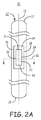
In various embodiments, a shoulder 242 that extends a housing outer side 218 laterally away from medial line 236 and longitudinal edge 234 of the sensor diaphragm 222, may be formed as a flange, ring, outcropping, or other projection. Such a projection will reduce contact pressure due to tissue encapsulation shrinkage over the area of the diaphragm 222 as compared to a relatively more narrow profile of the housing 212 adjacent diaphragm edge 234 that results in outer side 218 being relatively closer to the diaphragm medial line 236 than in the embodiment shown. Outer side 218 of shoulder 242 formed by the laterally extending protrusion or flange extends laterally outward with respect to an outer surface 250 of housing 212. It is contemplated that in other embodiments shell 226 may be formed with a flange or protruding portion defining a shoulder extending laterally away from longitudinal edge 234. In such embodiments, outer layer 228 can be formed with an approximately uniform wall thickness conforming to shell 226.
Additionally or alternatively, one or more channels 442 may be provided extending between inner surface 430 and outer surface 414 of layer 428 for receiving any excess medical adhesive applied between inner surface 430 and diaphragm 422. A medical adhesive coating applied between inner surface 430 and diaphragm 422 may back fill channel(s) 442 partially or completely to seal housing 420.
The various features described herein and shown in the accompanying drawings may be used alone or in any combination to reduce contact pressure on a sensor diaphragm. Thus, housings for medical sensor modules have been presented in the foregoing description with reference to specific embodiments. It is appreciated that various modifications to the referenced embodiments may be made without departing from the scope of the disclosure as set forth in the following claims.
Claims (24)
1. An implantable medical device, comprising:
a housing having an outer wall and comprising an inner shell and an outer layer formed to extend over and enclose the inner shell to form the outer wall, the inner shell having a thickness extending between an inner wall of the inner shell and an outer wall of the inner shell, the outer layer having an inner side engaged against the outer wall of the inner shell and having a thickness extending between the inner side and the outer wall of the housing, wherein the inner shell and the outer layer form a flat portion;
a flexible diaphragm formed within the inner shell along the flat portion and extending between a first edge and a second edge;
a shoulder extending adjacent to the first edge that extends the outer layer laterally away from a central medial line extending between the first and second edges of the diaphragm;
a recess portion formed between the diaphragm and the inner side of the outer layer; and
an over-fill channel formed by the outer layer and extending through the outer layer from an opening formed at the outer wall to an opening formed along the inner side of the outer layer extending along the flat portion.
2. The device of claim 1 , wherein the shoulder is formed by one or both of the inner shell and the outer layer to have a thickness to reduce contact pressure along the first edge and the second edge of the diaphragm to less than a predetermined percentage of a maximum contact pressure along the central median line.
3. The device of claim 2 , further comprising a second shoulder extending adjacent to the second edge of the diaphragm that extends the outer layer laterally away from the central medial line extending between the first and second edges of the diaphragm.
4. The device of claim 1 , wherein the shoulder comprises a flange extending laterally outward from the outer wall of the housing.
5. The device of claim 4 , wherein housing has a rectangular cross-section comprising a top side and a bottom side, the top side corresponding to the flat portion formed by the inner shell and the outer layer.
6. The device of claim 1 , wherein the thickness of the outer layer along the shoulder is greater than the thickness of the outer layer along a portion of the outer wall of the housing opposite the flat portion.
7. The device of claim 6 , wherein the thickness of the inner shell along the shoulder is approximately equal to the thickness of the inner shell along the portion of the outer wall of the housing opposite the flat portion.
8. The device of claim 1 , wherein the thickness of the inner shell along the shoulder is greater than the thickness of the inner shell along a portion of the outer wall of the housing opposite the flat portion.
9. The device of claim 8 , wherein the thickness of the outer layer along the shoulder is approximately equal to the thickness of the outer layer along the portion of the outer wall of the housing opposite the flat portion.
10. The device of claim 1 , wherein the thickness of the outer layer along the shoulder is greater than the thickness of the outer layer along a portion of the outer wall of the housing opposite the flat portion, and the thickness of the inner shell along the shoulder is greater than the thickness of the inner shell along the portion of the outer wall of the housing opposite the flat portion.
11. The device of claim 10 , wherein the thickness of the outer layer along the shoulder is equal to the thickness of the inner shell along the shoulder.
12. The device of claim 1 , wherein the over-fill channel extends through the shoulder.
13. An implantable medical device lead, comprising:
an elongated lead body;
a housing having an outer wall and comprising an inner shell and an outer layer formed to extend over and enclose the inner shell to form the outer wall, the inner shell having a thickness extending between an inner wall of the inner shell and an outer wall of the inner shell, the outer layer having an inner side engaged against the outer wall of the inner shell and having a thickness extending between the inner side and the outer wall of the housing, wherein the inner shell and the outer layer form a flat portion;
a flexible diaphragm formed within the inner shell along the flat portion and extending between a first edge and a second edge;
a shoulder extending adjacent to the first edge that extends the outer layer laterally away from a central medial line extending between the first and second edges of the diaphragm;
a recess portion formed between the diaphragm and the inner side of the outer layer; and
an over-fill channel formed by the outer layer and extending through the outer layer from an opening formed at the outer wall to an opening formed along the inner side of the outer layer extending along the flat portion.
14. The implantable medical device lead of claim 13 , wherein the shoulder is formed by one or both of the inner shell and the outer layer to have a thickness to reduce contact pressure along the first edge and the second edge of the diaphragm to less than a predetermined percentage of a maximum contact pressure along the central median line.
15. The implantable medical device lead of claim 14 , further comprising a second shoulder extending adjacent to the second edge of the diaphragm that extends the outer layer laterally away from the central medial line extending between the first and second edges of the diaphragm.
16. The implantable medical device lead of claim 13 , wherein the shoulder comprises a flange extending laterally outward from the outer wall of the housing.
17. The implantable medical device lead of claim 16 , wherein housing has a rectangular cross-section comprising a top side and a bottom side, the top side corresponding to the flat portion formed by the inner shell and the outer layer.
18. The implantable medical device lead of claim 13 , wherein the thickness of the outer layer along the shoulder is greater than the thickness of the outer layer along a portion of the outer wall of the housing opposite the flat portion.
19. The implantable medical device lead of claim 18 , wherein the thickness of the inner shell along the shoulder is approximately equal to the thickness of the inner shell along the portion of the outer wall of the housing opposite the flat portion.
20. The implantable medical device lead of claim 13 , wherein the thickness of the inner shell along the shoulder is greater than the thickness of the inner shell along a portion of the outer wall of the housing opposite the flat portion.
21. The implantable medical device lead of claim 20 , wherein the thickness of the outer layer along the shoulder is approximately equal to the thickness of the outer layer along the portion of the outer wall of the housing opposite the flat portion.
22. The implantable medical device lead of claim 13 , wherein the thickness of the outer layer along the shoulder is greater than the thickness of the outer layer along a portion of the outer wall of the housing opposite the flat portion, and the thickness of the inner shell along the shoulder is greater than the thickness of the inner shell along the portion of the outer wall of the housing opposite the flat portion.
23. The implantable medical device lead of claim 22 , wherein the thickness of the outer layer along the shoulder is equal to the thickness of the inner shell along the shoulder.
24. The implantable medical device lead of claim 13 , wherein the over-fill channel extends through the shoulder.
Priority Applications (4)
| Application Number | Priority Date | Filing Date | Title |
|---|---|---|---|
| US13/362,371 US9517032B2 (en) | 2012-01-31 | 2012-01-31 | Sensor over-mold shape |
| CN201280068575.6A CN104093352B (en) | 2012-01-31 | 2012-11-21 | Sensor cladding mould shape |
| PCT/US2012/066171 WO2013115899A1 (en) | 2012-01-31 | 2012-11-21 | Sensor over-mold shape |
| EP12805490.5A EP2809226B1 (en) | 2012-01-31 | 2012-11-21 | Sensor comprising overflow channel |
Applications Claiming Priority (1)
| Application Number | Priority Date | Filing Date | Title |
|---|---|---|---|
| US13/362,371 US9517032B2 (en) | 2012-01-31 | 2012-01-31 | Sensor over-mold shape |
Publications (2)
| Publication Number | Publication Date |
|---|---|
| US20130197336A1 US20130197336A1 (en) | 2013-08-01 |
| US9517032B2 true US9517032B2 (en) | 2016-12-13 |
Family
ID=48870814
Family Applications (1)
| Application Number | Title | Priority Date | Filing Date |
|---|---|---|---|
| US13/362,371 Active 2035-02-07 US9517032B2 (en) | 2012-01-31 | 2012-01-31 | Sensor over-mold shape |
Country Status (1)
| Country | Link |
|---|---|
| US (1) | US9517032B2 (en) |
Families Citing this family (6)
| Publication number | Priority date | Publication date | Assignee | Title |
|---|---|---|---|---|
| US9517032B2 (en) * | 2012-01-31 | 2016-12-13 | Medtronic, Inc. | Sensor over-mold shape |
| US10429252B1 (en) | 2016-08-26 | 2019-10-01 | W. L. Gore & Associates, Inc. | Flexible capacitive pressure sensor |
| US10307067B1 (en) | 2016-08-26 | 2019-06-04 | W. L. Gore & Associates, Inc. | Wireless LC sensor reader |
| US11284840B1 (en) | 2016-08-26 | 2022-03-29 | W. L. Gore & Associates, Inc. | Calibrating passive LC sensor |
| US10240994B1 (en) | 2016-08-26 | 2019-03-26 | W. L. Gore & Associates, Inc. | Wireless cylindrical shell passive LC sensor |
| DE102020213718A1 (en) | 2020-11-02 | 2022-05-05 | Robert Bosch Gesellschaft mit beschränkter Haftung | Medical implant |
Citations (33)
| Publication number | Priority date | Publication date | Assignee | Title |
|---|---|---|---|---|
| US3418853A (en) | 1966-01-10 | 1968-12-31 | Statham Instrument Inc | Blood pressure transducer |
| US3748623A (en) | 1972-07-25 | 1973-07-24 | Millar Instruments | Pressure transducers |
| US4507973A (en) | 1983-08-31 | 1985-04-02 | Borg-Warner Corporation | Housing for capacitive pressure sensor |
| US4901735A (en) | 1988-10-04 | 1990-02-20 | Peter Von Berg Extrakorporale Systeme - Medizintechnik Gmbh | Pressure meter catheter with in-situ zero setting |
| US5067491A (en) | 1989-12-08 | 1991-11-26 | Becton, Dickinson And Company | Barrier coating on blood contacting devices |
| US5353800A (en) | 1992-12-11 | 1994-10-11 | Medtronic, Inc. | Implantable pressure sensor lead |
| US5535752A (en) * | 1995-02-27 | 1996-07-16 | Medtronic, Inc. | Implantable capacitive absolute pressure and temperature monitor system |
| US5540731A (en) | 1994-09-21 | 1996-07-30 | Medtronic, Inc. | Method and apparatus for pressure detecting and treating obstructive airway disorders |
| US5554176A (en) | 1986-05-15 | 1996-09-10 | Telectronics Pacing Systems, Inc. | Implantable electrode and sensor lead apparatus |
| US5564434A (en) * | 1995-02-27 | 1996-10-15 | Medtronic, Inc. | Implantable capacitive absolute pressure and temperature sensor |
| US5755766A (en) | 1997-01-24 | 1998-05-26 | Cardiac Pacemakers, Inc. | Open-ended intravenous cardiac lead |
| CN1292084A (en) | 1999-01-07 | 2001-04-18 | 韦尔奇阿林公司 | Low-contour pressure measurer |
| US6221024B1 (en) | 1998-07-20 | 2001-04-24 | Medtronic, Inc. | Implantable pressure sensor and method of fabrication |
| US6331161B1 (en) | 1999-09-10 | 2001-12-18 | Hypertension Diagnostics, Inc | Method and apparatus for fabricating a pressure-wave sensor with a leveling support element |
| US6572543B1 (en) | 1996-06-26 | 2003-06-03 | Medtronic, Inc | Sensor, method of sensor implant and system for treatment of respiratory disorders |
| US6580946B2 (en) | 2001-04-26 | 2003-06-17 | Medtronic, Inc. | Pressure-modulated rate-responsive cardiac pacing |
| US20060116588A1 (en) | 1993-11-09 | 2006-06-01 | Archibald G K | Method and apparatus for calculating blood pressure of an artery |
| US7231259B2 (en) | 2002-10-04 | 2007-06-12 | Pacesetter, Inc. | Body implantable lead comprising electrically conductive polymer conductors |
| US7231829B2 (en) | 2005-03-31 | 2007-06-19 | Medtronic, Inc. | Monolithic integrated circuit/pressure sensor on pacing lead |
| US7367951B2 (en) | 2005-01-27 | 2008-05-06 | Medtronic, Inc. | System and method for detecting cardiovascular health conditions using hemodynamic pressure waveforms |
| US7591185B1 (en) | 2008-04-23 | 2009-09-22 | Medtronic, Inc. | Pressure sensor configurations for implantable medical electrical leads |
| US20090248125A1 (en) * | 2008-03-25 | 2009-10-01 | Medtronic, Inc. | Integrated conductive pressure sensor capsule with custom molded unitary overlay |
| US7614308B2 (en) | 2007-12-20 | 2009-11-10 | Inficon Gmbh | Diaphragm pressure measuring cell arrangement |
| US20090299429A1 (en) | 2008-06-02 | 2009-12-03 | Medtronic, Inc. | Sensing integrity determination based on cardiovascular pressure |
| US20100076519A1 (en) | 2005-12-29 | 2010-03-25 | Medtronic, Inc. | System and method for regulating blood pressure and electrolyte balance |
| CN101983031A (en) | 2008-03-05 | 2011-03-02 | 罗伯特·霍克 | Pressure sensing catheter |
| CN102137620A (en) | 2008-08-28 | 2011-07-27 | 皇家飞利浦电子股份有限公司 | Device, apparatus and method for obtaining physiological signals by way of a feeding tube |
| US20110257593A1 (en) * | 2007-03-30 | 2011-10-20 | Medtronic, Inc. | Devices and methods for detecting catheter complications |
| US8127618B1 (en) * | 2007-05-18 | 2012-03-06 | Pacesetter, Inc. | Implantable micro-electromechanical system sensor |
| US20120197155A1 (en) * | 2011-01-28 | 2012-08-02 | Medtronic, Inc. | Implantable Capacitive Pressure Sensor Apparatus and Methods Regarding Same |
| US20130197396A1 (en) * | 2012-01-31 | 2013-08-01 | Medtronic, Inc. | Sensor over-mold shape |
| US20130197336A1 (en) * | 2012-01-31 | 2013-08-01 | Medtronic, Inc. | Sensor over-mold shape |
| US9131858B2 (en) | 2012-01-31 | 2015-09-15 | Medtronic, Inc. | Sensor over-mold shape |
-
2012
- 2012-01-31 US US13/362,371 patent/US9517032B2/en active Active
Patent Citations (36)
| Publication number | Priority date | Publication date | Assignee | Title |
|---|---|---|---|---|
| US3418853A (en) | 1966-01-10 | 1968-12-31 | Statham Instrument Inc | Blood pressure transducer |
| US3748623A (en) | 1972-07-25 | 1973-07-24 | Millar Instruments | Pressure transducers |
| US4507973A (en) | 1983-08-31 | 1985-04-02 | Borg-Warner Corporation | Housing for capacitive pressure sensor |
| US5554176A (en) | 1986-05-15 | 1996-09-10 | Telectronics Pacing Systems, Inc. | Implantable electrode and sensor lead apparatus |
| US4901735A (en) | 1988-10-04 | 1990-02-20 | Peter Von Berg Extrakorporale Systeme - Medizintechnik Gmbh | Pressure meter catheter with in-situ zero setting |
| US5067491A (en) | 1989-12-08 | 1991-11-26 | Becton, Dickinson And Company | Barrier coating on blood contacting devices |
| US5353800A (en) | 1992-12-11 | 1994-10-11 | Medtronic, Inc. | Implantable pressure sensor lead |
| US20060116588A1 (en) | 1993-11-09 | 2006-06-01 | Archibald G K | Method and apparatus for calculating blood pressure of an artery |
| US5540731A (en) | 1994-09-21 | 1996-07-30 | Medtronic, Inc. | Method and apparatus for pressure detecting and treating obstructive airway disorders |
| US5564434A (en) * | 1995-02-27 | 1996-10-15 | Medtronic, Inc. | Implantable capacitive absolute pressure and temperature sensor |
| US5535752A (en) * | 1995-02-27 | 1996-07-16 | Medtronic, Inc. | Implantable capacitive absolute pressure and temperature monitor system |
| US6572543B1 (en) | 1996-06-26 | 2003-06-03 | Medtronic, Inc | Sensor, method of sensor implant and system for treatment of respiratory disorders |
| US5755766A (en) | 1997-01-24 | 1998-05-26 | Cardiac Pacemakers, Inc. | Open-ended intravenous cardiac lead |
| US6221024B1 (en) | 1998-07-20 | 2001-04-24 | Medtronic, Inc. | Implantable pressure sensor and method of fabrication |
| CN1292084A (en) | 1999-01-07 | 2001-04-18 | 韦尔奇阿林公司 | Low-contour pressure measurer |
| US6331161B1 (en) | 1999-09-10 | 2001-12-18 | Hypertension Diagnostics, Inc | Method and apparatus for fabricating a pressure-wave sensor with a leveling support element |
| US6580946B2 (en) | 2001-04-26 | 2003-06-17 | Medtronic, Inc. | Pressure-modulated rate-responsive cardiac pacing |
| US7231259B2 (en) | 2002-10-04 | 2007-06-12 | Pacesetter, Inc. | Body implantable lead comprising electrically conductive polymer conductors |
| US7367951B2 (en) | 2005-01-27 | 2008-05-06 | Medtronic, Inc. | System and method for detecting cardiovascular health conditions using hemodynamic pressure waveforms |
| US7231829B2 (en) | 2005-03-31 | 2007-06-19 | Medtronic, Inc. | Monolithic integrated circuit/pressure sensor on pacing lead |
| US20100076519A1 (en) | 2005-12-29 | 2010-03-25 | Medtronic, Inc. | System and method for regulating blood pressure and electrolyte balance |
| US20110257593A1 (en) * | 2007-03-30 | 2011-10-20 | Medtronic, Inc. | Devices and methods for detecting catheter complications |
| US8127618B1 (en) * | 2007-05-18 | 2012-03-06 | Pacesetter, Inc. | Implantable micro-electromechanical system sensor |
| US7614308B2 (en) | 2007-12-20 | 2009-11-10 | Inficon Gmbh | Diaphragm pressure measuring cell arrangement |
| CN101983031A (en) | 2008-03-05 | 2011-03-02 | 罗伯特·霍克 | Pressure sensing catheter |
| US8723361B2 (en) | 2008-03-05 | 2014-05-13 | Reliance Controls Corporation | Automatic transfer switch having an interlock arrangement |
| US20090248125A1 (en) * | 2008-03-25 | 2009-10-01 | Medtronic, Inc. | Integrated conductive pressure sensor capsule with custom molded unitary overlay |
| US7591185B1 (en) | 2008-04-23 | 2009-09-22 | Medtronic, Inc. | Pressure sensor configurations for implantable medical electrical leads |
| US20090299429A1 (en) | 2008-06-02 | 2009-12-03 | Medtronic, Inc. | Sensing integrity determination based on cardiovascular pressure |
| US8613702B2 (en) | 2008-08-28 | 2013-12-24 | Koniklijke Philips N.V. | Device, apparatus and method for obtaining physiological signals by way of a feeding tube |
| CN102137620A (en) | 2008-08-28 | 2011-07-27 | 皇家飞利浦电子股份有限公司 | Device, apparatus and method for obtaining physiological signals by way of a feeding tube |
| US20120197155A1 (en) * | 2011-01-28 | 2012-08-02 | Medtronic, Inc. | Implantable Capacitive Pressure Sensor Apparatus and Methods Regarding Same |
| US20130197396A1 (en) * | 2012-01-31 | 2013-08-01 | Medtronic, Inc. | Sensor over-mold shape |
| US20130197336A1 (en) * | 2012-01-31 | 2013-08-01 | Medtronic, Inc. | Sensor over-mold shape |
| US9005134B2 (en) | 2012-01-31 | 2015-04-14 | Medtronic, Inc. | Sensor over-mold shape |
| US9131858B2 (en) | 2012-01-31 | 2015-09-15 | Medtronic, Inc. | Sensor over-mold shape |
Non-Patent Citations (5)
| Title |
|---|
| Chinese office action for application No. 201280068575.6, English translation, mailed Oct. 10, 2015, 5 pages. |
| Chinese office action for application No. 201280068575.6, mailed Oct. 10, 2015, 6 pages. |
| Communication from EPO for application No. 12805490.5, mailed Sep. 3, 2015, 4 pages. |
| Office Action mailed Sep. 12, 2014 for U.S. Appl. No. 13/362,270. |
| PCT/US2012/066171 PCT Notification of Transmittal of the International Search Report and the Written Opinion of the International Searching Authority, mailed Mar. 12, 2013, 11 pages. |
Also Published As
| Publication number | Publication date |
|---|---|
| US20130197336A1 (en) | 2013-08-01 |
Similar Documents
| Publication | Publication Date | Title |
|---|---|---|
| US9517032B2 (en) | Sensor over-mold shape | |
| US20220202304A1 (en) | Wireless intracranial monitoring system | |
| US7591185B1 (en) | Pressure sensor configurations for implantable medical electrical leads | |
| US8849424B2 (en) | Integrated conductive sensor package having conductor bypass, distal electrode, distal adapter and custom molded overlay | |
| TWI446896B (en) | Sensor for acquiring muscle parameters | |
| US20230255517A1 (en) | Highly integrated analyte detection device | |
| US20090248125A1 (en) | Integrated conductive pressure sensor capsule with custom molded unitary overlay | |
| US20120296445A1 (en) | Liner having an integrated electrode | |
| US10729360B2 (en) | Sensor cable support device including mechanical connectors | |
| JP2016145827A (en) | Implantable device for measuring intracorporeal pressure, featuring remote transmission of measured values | |
| US20170202513A1 (en) | Implantable pressure sensors and medical devices | |
| US9131858B2 (en) | Sensor over-mold shape | |
| US9005134B2 (en) | Sensor over-mold shape | |
| EP2809226B1 (en) | Sensor comprising overflow channel | |
| US20210290087A1 (en) | Sensor head device for a minimal invasive ventricular assist device and method for producing such a sensor head device | |
| US20110288436A1 (en) | Materials and methods for insulating electronic components and services | |
| CN107530008A (en) | Sensor unit | |
| US8172760B2 (en) | Medical device encapsulated within bonded dies | |
| US20230106499A1 (en) | Pressure sensor | |
| US20110028852A1 (en) | Implantable Pressure Sensor with Membrane Bridge | |
| EP3361938A1 (en) | Wireless intracranial monitoring system | |
| JP2014033871A (en) | Organism information detector | |
| JP2020048942A (en) | Pulse wave sensor |
Legal Events
| Date | Code | Title | Description |
|---|---|---|---|
| AS | Assignment |
Owner name: MEDTRONIC, INC., MINNESOTA Free format text: ASSIGNMENT OF ASSIGNORS INTEREST;ASSIGNORS:FLO, DANIEL S;CARNEY, JAMES K;MOTHILAL, KAMAL DEEP;AND OTHERS;REEL/FRAME:035114/0461 Effective date: 20120130 |
|
| STCF | Information on status: patent grant |
Free format text: PATENTED CASE |
|
| MAFP | Maintenance fee payment |
Free format text: PAYMENT OF MAINTENANCE FEE, 4TH YEAR, LARGE ENTITY (ORIGINAL EVENT CODE: M1551); ENTITY STATUS OF PATENT OWNER: LARGE ENTITY Year of fee payment: 4 |