US9527153B2 - Camera and wire feed solution for orbital welder system - Google Patents

Camera and wire feed solution for orbital welder system Download PDF

Info

Publication number
US9527153B2
US9527153B2 US13/830,945 US201313830945A US9527153B2 US 9527153 B2 US9527153 B2 US 9527153B2 US 201313830945 A US201313830945 A US 201313830945A US 9527153 B2 US9527153 B2 US 9527153B2
Authority
US
United States
Prior art keywords
camera device
bracket
arm
wire guide
welding
Prior art date
Legal status (The legal status is an assumption and is not a legal conclusion. Google has not performed a legal analysis and makes no representation as to the accuracy of the status listed.)
Expired - Fee Related, expires
Application number
US13/830,945
Other versions
US20140263249A1 (en
Inventor
Victor Miller
Current Assignee (The listed assignees may be inaccurate. Google has not performed a legal analysis and makes no representation or warranty as to the accuracy of the list.)
Lincoln Global Inc
Original Assignee
Lincoln Global Inc
Priority date (The priority date is an assumption and is not a legal conclusion. Google has not performed a legal analysis and makes no representation as to the accuracy of the date listed.)
Filing date
Publication date
Application filed by Lincoln Global Inc filed Critical Lincoln Global Inc
Priority to US13/830,945 priority Critical patent/US9527153B2/en
Assigned to LINCOLN GLOBAL, INC. reassignment LINCOLN GLOBAL, INC. ASSIGNMENT OF ASSIGNORS INTEREST (SEE DOCUMENT FOR DETAILS). Assignors: MILLER, VICTOR
Priority to CN201480015386.1A priority patent/CN105189008B/en
Priority to JP2015600142U priority patent/JP3203667U/en
Priority to DE212014000075.0U priority patent/DE212014000075U1/en
Priority to PCT/IB2014/000300 priority patent/WO2014140730A2/en
Publication of US20140263249A1 publication Critical patent/US20140263249A1/en
Application granted granted Critical
Publication of US9527153B2 publication Critical patent/US9527153B2/en
Expired - Fee Related legal-status Critical Current
Adjusted expiration legal-status Critical

Links

Images

Classifications

    • BPERFORMING OPERATIONS; TRANSPORTING
    • B23MACHINE TOOLS; METAL-WORKING NOT OTHERWISE PROVIDED FOR
    • B23KSOLDERING OR UNSOLDERING; WELDING; CLADDING OR PLATING BY SOLDERING OR WELDING; CUTTING BY APPLYING HEAT LOCALLY, e.g. FLAME CUTTING; WORKING BY LASER BEAM
    • B23K9/00Arc welding or cutting
    • B23K9/095Monitoring or automatic control of welding parameters
    • B23K9/0956Monitoring or automatic control of welding parameters using sensing means, e.g. optical
    • BPERFORMING OPERATIONS; TRANSPORTING
    • B23MACHINE TOOLS; METAL-WORKING NOT OTHERWISE PROVIDED FOR
    • B23KSOLDERING OR UNSOLDERING; WELDING; CLADDING OR PLATING BY SOLDERING OR WELDING; CUTTING BY APPLYING HEAT LOCALLY, e.g. FLAME CUTTING; WORKING BY LASER BEAM
    • B23K9/00Arc welding or cutting
    • B23K9/02Seam welding; Backing means; Inserts
    • B23K9/028Seam welding; Backing means; Inserts for curved planar seams
    • B23K9/0282Seam welding; Backing means; Inserts for curved planar seams for welding tube sections
    • B23K9/0286Seam welding; Backing means; Inserts for curved planar seams for welding tube sections with an electrode moving around the fixed tube during the welding operation
    • BPERFORMING OPERATIONS; TRANSPORTING
    • B23MACHINE TOOLS; METAL-WORKING NOT OTHERWISE PROVIDED FOR
    • B23KSOLDERING OR UNSOLDERING; WELDING; CLADDING OR PLATING BY SOLDERING OR WELDING; CUTTING BY APPLYING HEAT LOCALLY, e.g. FLAME CUTTING; WORKING BY LASER BEAM
    • B23K9/00Arc welding or cutting
    • B23K9/12Automatic feeding or moving of electrodes or work for spot or seam welding or cutting
    • B23K9/122Devices for guiding electrodes, e.g. guide tubes
    • BPERFORMING OPERATIONS; TRANSPORTING
    • B23MACHINE TOOLS; METAL-WORKING NOT OTHERWISE PROVIDED FOR
    • B23KSOLDERING OR UNSOLDERING; WELDING; CLADDING OR PLATING BY SOLDERING OR WELDING; CUTTING BY APPLYING HEAT LOCALLY, e.g. FLAME CUTTING; WORKING BY LASER BEAM
    • B23K9/00Arc welding or cutting
    • B23K9/32Accessories
    • BPERFORMING OPERATIONS; TRANSPORTING
    • B23MACHINE TOOLS; METAL-WORKING NOT OTHERWISE PROVIDED FOR
    • B23KSOLDERING OR UNSOLDERING; WELDING; CLADDING OR PLATING BY SOLDERING OR WELDING; CUTTING BY APPLYING HEAT LOCALLY, e.g. FLAME CUTTING; WORKING BY LASER BEAM
    • B23K2101/00Articles made by soldering, welding or cutting
    • B23K2101/04Tubular or hollow articles
    • B23K2101/06Tubes
    • B23K2201/06

Abstract

The technology described herein generally pertains to a system related to a camera device and wire guide system that includes a bracket for a wire guide and a camera device, wherein the bracket aligns the camera device to aim on a position of a welding zone for an orbital welding system. In particular, the bracket supports a wire guide to be positioned on a welding zone while also supporting a camera device that can be positioned on the welding zone. The bracket enables the welding zone to be captured by the camera device and is centered on the wire guide to remain positioned on the welding zone. The bracket provides placement of a camera device to provide video/camera visibility of the welding zone while allows adjustment of the camera device with wire location adjustment or independent of wire location adjustment.

Description

TECHNICAL FIELD
In general, the present invention relates to a camera and mounting device used in connection with an orbital welding system. More particularly, the present invention relates to a camera mounting device that couples to a portion of a welding system while providing versatile adjustment for a camera to focus on a welding zone.
BACKGROUND OF THE INVENTION
In industrial applications, welding may involve, raising, cladding, building up, filling, hard facing, overlaying, joining, and other welding applications. When confronted with a workpiece having a curved surface, an orbital welding processes may be used to rotate the welding head to apply a weld to the curved surface. The most common examples, where orbital welding is used, is the welding of pipe. Pipe welding may include thin wall application where the welding head is rotated about the other surface two piece ends being joined together, alternatively, pipe welding may include deep grove geometries where the welding electrode extends into a grove formed between the two pipes being joined to lay down successive beads of weld material to fill the grove the join the thick walled pipes. Orbital welding systems may include a welding head that is mounted on a guide track or a fixture that clamps or is otherwise supported on the workpiece and rotated to supply a weld. With orbital welding often involves limited visibility of a welding zone with lead cameras and/or trailing cameras.
Orbital welding systems can be compromised by the deep grove geometries and curvature associated with a workpiece and what is needed is an improved technique to related to orbital welding systems.
SUMMARY OF THE INVENTION
In accordance with an embodiment of the present invention, a welding system is provided that an orbital welder having a chassis that is attached to a workpiece and supported on a portion of track affixed to the workpiece and a welding torch coupled to the chassis that includes an electrode an electrode adapted to form a weld joint on the workpiece. The welder system further includes a wire feeder that is connected to a supply of welding wire to provide welding wire to a wire guide to a welding zone at which the electrode deposits weld material on the workpiece. In accordance with the aspect, the welder system includes a bracket coupled to the chassis that comprises includes a first arm in a first plane, wherein a portion of the first arm is adapted to focus a camera device on the welding zone and a second arm having an offset portion lying in a second plane separated by a distance from the first plane defining a recess to receive at least a portion of the camera device, wherein the second arm includes a wire guide mount that supports the wire guide in the first plane to provide the welding wire to the welding zone.
In accordance with an embodiment of the present invention, a bracket for mounting a camera device to a welder system is provided that includes a first arm situated in a first plane that includes a top portion and a bottom portion opposite thereof. In accordance with the bracket, the bottom portion includes a camera device mount that receives a first portion of a camera device, wherein the camera device is positioned to aim at a welding zone. The bracket further includes a second arm having an offset portion lying in a second plane separated by a distance from the first plane to define a recess to receive a second portion of the camera device, wherein the second arm includes a wire guide mount that supports the wire guide in the first plane to provide a portion of welding wire to the welding zone. With the bracket, a center point of the camera mount device lies in the same plane as a center point of the wire guide mount.
In accordance with an embodiment of the present invention, an orbital welding system is provide that includes an orbital welder having a chassis that is attached to a workpiece and supported on a portion of track affixed to the workpiece and a welding torch coupled to the chassis that includes an electrode adapted to form a weld joint on the workpiece. The orbital welding system further includes a wire feeder that is connected to a supply of welding wire to provide welding wire to a wire guide to a welding zone at which the electrode deposits weld material on the workpiece. In accordance with the orbital welding system, a bracket coupled to the chassis is provided that includes a first arm in a first plane, wherein a portion of the first arm is adapted to focus a camera device on the welding zone and a second arm having an offset portion lying in a second plane separated by a distance from the first plane defining a recess to receive at least a portion of the camera device, wherein the second arm includes a wire guide mount that supports the wire guide in the first plane to aim in a position on the welding zone. In the orbital welding system, the second arm further includes a top portion and a bottom portion opposite thereof, a first transition that transitions from the top portion to the offset portion, and a second transition that transitions from the offset portion to at least one of the wire guide mount or the bottom portion, wherein the first transition, offset portion and second transition form a continuous curve.
These and other objects of this invention will be evident when viewed in light of the drawings, detailed description and appended claims.
BRIEF DESCRIPTION OF THE DRAWINGS
The invention may take physical form in certain parts and arrangements of parts, a preferred embodiment of which will be described in detail in the specification and illustrated in the accompanying drawings which form a part hereof, and wherein:
FIG. 1 illustrates a front view of an orbital welding system that includes a first mount system and a second mount system to support a camera device and a wire guide to position on a welding zone;
FIG. 2A illustrates a side view of an orbital welding system that includes a first mount system and a second mount system to support a camera device and a wire guide to position on a welding zone;
FIG. 2B illustrates a perspective view of an orbital welding system that includes a first mount system and a second mount system to support a camera device and a wire guide to position on a welding zone;
FIG. 3A illustrates a front view of a first camera device and wire guide system that supports a camera device and a wire guide for an orbital welding system;
FIG. 3B illustrates a perspective view of a first camera device and wire guide system that supports a camera device and a wire guide for an orbital welding system;
FIG. 4A illustrates a front view of a second camera device and wire guide system that supports a camera device and a wire guide for an orbital welding system;
FIG. 4B illustrates a perspective view of a second camera device and wire guide system that supports a camera device and a wire guide for an orbital welding system;
FIG. 5 illustrates a side view of a second camera device and wire guide system that supports a camera device and a wire guide for an orbital welding system; and
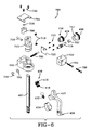
FIG. 6 illustrates an exploded view of a second camera device and wire guide system that supports a camera device and a wire guide for an orbital welding system.
DETAILED DESCRIPTION OF THE INVENTION
Embodiments of the invention relate to methods and systems that relate to camera device and wire guide system that includes a bracket for a wire guide and a camera device, wherein the bracket aligns the camera device to aim on a position of a welding zone for an orbital welding system. In particular, the bracket supports a wire guide to be positioned on a welding zone while also supporting a camera device that can be positioned on the welding zone. The bracket enables the welding zone to be captured by the camera device and is centered on the wire guide to remain positioned on the welding zone. The bracket provides placement of a camera device to provide video/camera visibility of the welding zone while allows adjustment of the camera device with wire location adjustment or independent of wire location adjustment. Moreover, a wire guide and camera device system can include a bracket and a height adjustment device that maneuvers the bracket (and affixed camera device and wire guide) upwards away the welding zone or downwards toward the welding zone.
“Welding” or “weld” as used herein including any other formatives of these words will refer to depositing of molten material through the operation of an electric arc including but not limited to submerged arc, GMAW, MAG, MIG, TIG welding, or any electric arc used with an orbital welding system.
The best mode for carrying out the invention will now be described for the purposes of illustrating the best mode known to the applicant at the time of the filing of this patent application. The examples and figures are illustrative only and not meant to limit the invention, which is measured by the scope and spirit of the claims. Referring now to the drawings, wherein the showings are for the purpose of illustrating an exemplary embodiment of the invention only and not for the purpose of limiting same, FIGS. 1-6 illustrate a camera device and wire guide mounting system that is used with an automated or semi-automated welding system. One illustrative example of a welding system is orbital welding, which is often used for the joining of tubes or pipes of various types of materials. For example, a Tungsten Inert Gas (TIG) or Gas Tungsten Arc Welding (GTAW) welding torch may be used to orbit around the pipes to be welded together by an automated mechanical system. FIGS. 1-2B illustrates an example embodiment of orbital welding system 100 (also referred to as welder, system, and/or welder system) as used in an orbital welding environment. Orbital welding system 100 includes a welding tractor (not shown) that travels around the pipes or tubes, a welding power source (not shown) and controller (not shown), and a pendant (not shown) providing operator control.
System 100 (as seen in FIGS. 1-2B) is generally used in deep groove welding. In the example shown, welding system 100 includes an orbital TIG welder having a welder body or chassis 101, which may be attached to the work piece or supported on a track. Welder 100 includes a welding torch, generally indicated at 30, having a welding electrode 32 for depositing weld material to form a weld joint at welding zone Z. Electrode 32 is an extended electrode having an electrode length suitable for the groove G being welded. Extended electrode 32 may have any length suitable for a given deep groove weld, including lengths greater than 10 millimeters. As depicted in the example shown, electrode length may be greater than 100 millimeters. The particular example shown has a length of about 120 millimeters. This example is not limiting as electrodes having greater or lesser lengths may be used depending on the depth of the groove G.
Welding torch 30 is connected to a shield gas supply 106, that provides an inert gas, such as Argon gas, to welding torch 30. Welding gas supply 106 may include a container, such as a cylinder, that stores shield gas S under pressure, and delivery of shield gas S, via appropriate tubing or other conduits, may be controlled by a regulator or other controller 107. A non-pressurized source may be used also with gas delivery provided by a pump or the like. When welding thick plates or heavy wall pipes, the weld joint design typically provides a narrow groove to permit an elongated electrode to be placed in the joint with some adjustment of the torch angle to assure a good weld created by layering a series of weld beads upon each other until the joint is filled. This process may be referred to as narrow groove welding or deep groove welding interchangeably throughout the following description. Narrow groove welding is a process where successive single bead weld layers are applied on top of one another in a narrow groove or joint. One of the considerations in the narrow groove environment is maintaining sufficient shield gas to protect the molten weld puddle from atmospheric contamination. Typically, an inert shield gas, such as Argon, is provided from outside the weld joint with a long electrode extending into the groove below the shield gas supply.
The welder may include a wire feeder connected to a supply of welding wire, such as a spool 103 that provides tungsten wire W to one or more wire guides 104′, 104. In the example shown, a pair of extended wire guides 104′, 104 are provided and fed by independent spools 103 located on either side of chassis 101. The extended wire guides 104′, 104 are supported on first camera device and wire guide system 105 (also referred to as first mount system 105) and second camera device and wire guide system 106 (also referred to as second mount system 106) respectively that are each laterally outward of electrode 32 and above the workpiece or pipe P. Wire guides 104′, 104 extend inward and downward toward electrode 32 and welding zone Z. The example welder is supported on a track and drive by a tractor drive around pipe with wire guides 104′, 104 being located in lead and lag positions relative to welding electrode 32. First mount system 105 is coupled to height adjustment device 130 that allows adjustment of first mount system 105 toward welding zone Z or away welding zone Z. Height adjustment device 130 is further coupled to support member 132 that is coupled to a portion of chassis 101 of welder system 100. Similarly, second mount system 106 is coupled to height adjustment device 124 that allows adjustment of second mount system 106 toward welding zone Z or away welding zone Z. Height adjustment device 124 is further coupled to support member 126 that is coupled to a portion of chassis 101 of welder system 100. It is to be appreciated that first mount system 105 and height adjustment device 130 can be referred to as a camera device and wire guide system and second mount system 106 and height adjustment device 124 can be referred to as a camera device and wire guide system.
First mount system 105 supports camera device 113, camera device first portion 114, camera device second portion 116, and wire guide 104′, wherein both camera device 113 and wire guide 104′ are positioned to aim on or toward welding zone Z. Similarly, second mount system 106 supports camera device 112 and wire guide 104, wherein both camera device 112 and wire guide 104 are positioned to aim on or toward welding zone Z. In other words, first mount system 105 and second mount system 106 allow camera device alignment in which a view of camera device is focused on welding zone Z which is also where wire guides 104′, 104 feed wire for depositing welding material. Thus, first mount system 105 connects camera device 113 to wire guide 104′ to allow independent alignment or positioning of one another. It is to be appreciated that first mount system 105 afford alignment or positioning of camera device 113 and wire guide 104′ together. Once configured in terms of alignment or positioning, camera device 113 and wire guide 104′ move together with welder system 100 which enables camera device 113 to capture media consistently at welding zone Z and/or where wire is feed from wire guide 104′. Furthermore, second mount system 106 connects camera device 112 to wire guide 104 to allow independent alignment or positioning of one another. It is to be appreciated that second mount system 106 afford alignment or positioning of camera device 112 and wire guide 104 together. Once configured in terms of alignment or positioning, camera device 112, camera device first portion 118, camera device second portion 120, and wire guide 104 move together with welder system 100 which enables camera device 112 to capture media consistently at welding zone Z and/or where wire is feed from wire guide 104.
It is to be appreciated that camera devices 112, 113 can be any suitable device that captures media (e.g., video, images, pictures, among others) such as a camera, a video camera, a web camera, a thermal imaging device, a thermal device, an infrared camera, among others. Still, any camera device may be chosen with sound engineering judgment without departing from the intended scope of coverage of the embodiments of the subject invention. First mount system 105 and/or second mount system 106 are constructed from a combination of materials selected from the group consisting of a copper, an alloy of copper, beryllium copper, copper tungsten, a conductive metal, a steel, a ceramic, an aluminum, among others. Yet, any shape, size, dimensions, or material may be chosen with sound engineering judgment without departing from the intended scope of coverage of the embodiments of the subject invention.
System 100 provides a flexibility of adjustment for at least one of camera devices 112, 113 and wire guides 104, 104′. Camera devices 112, 113 can include eight (8) axes of camera movement (e.g., three (3) in conjunction with wire nozzle adjustment (e.g., also referred to as wire guide 104′, 104) and five (5) independent of wire nozzle adjustment (e.g., wire guide 104′, 104) which includes three (3) on a ball joint, one (1) in and out, and one (1) twisting). In an embodiment, a first arm of the bracket (e.g., first mount system 105 or second mount system 106) can be centered with the wire guide (e.g., wire guide 104′ or wire guide 104) and moves side to side and up and down along with the wire dispensed so an image of the camera device remains locked on weld zone Z (discussed in more detail below).
Turning to FIGS. 3A and 3B, first mount system 105 is illustrated with a front view and a perspective view respectively. First mount system 105 includes height adjustment device 130 that includes rail 302, knob 304, and knob 306. Height adjustment device 130 utilizes rail 302 to move in a vertical direction (e.g., toward the workpiece and welding zone Z or away from the workpiece and welding zone Z). Rail 302 can include a plurality of teeth to which a gear engages in a rack and pinion fashion (not shown but discussed in FIG. 6) is turned to enable movement. It is contemplated that other linear actuators may be used to the same effect as the rack and pinion system shown.
Rotation of gear can be facilitated by knob 306. It is to be appreciated that reference to knob 306 includes other suitable mechanism (e.g., crank, screw, lever, electrical device, among others) that turns or rotates the gear to move about the plurality of teeth. Height adjustment device 130 further includes knob 304 that is configured to enable an adjustment of movement for first mount system 105. For instance, turning knob 304 can maneuver first mount system 105 forward or backward (e.g., referring to FIG. 2, forward direction is to the left and backward direction is to the right). It is to be appreciated that knob 304 can be any suitable mechanism (e.g., crank, screw, lever, electrical device, among others) that turns or rotates to move first mount system forward or backward based on the direction moved.
Rail 302 includes a top end and a bottom end opposite thereto, wherein the opposite end can include apertures 320 for connecting bracket 318 thereto via one or more fasteners. In an embodiment, apertures 320 allow further adjustment of bracket 318 in a horizontal direction (e.g., side to side direction in relation to welding zone Z) and/or vertical direction (e.g., up and down direction in relation to welding zone Z). For instance, bracket 318 can include a top aperture, a middle aperture, and a bottom aperture, wherein the top aperture and bottom aperture allow horizontal adjustment and/or vertical adjustment for bracket 318. In a particular embodiment, a top aperture and a bottom aperture can be capsule shaped to allow bracket 318 to be adjusted in a horizontal direction and/or vertical direction and secured with a fastener at a desired location.
Bracket 318 includes first arm 308 and second arm 309, wherein first arm 308 includes a top portion and a bottom portion opposite thereof, wherein the bottom portion includes camera device mount 314. It is to be appreciated that camera device mount 314 supports a camera device (e.g., camera device 113). First arm 308 resides in a first plane, whereas second arm 309 resides in a second plane (See FIG. 6 for discussion of first plane and second plane). The first plane and the second plane are separated by a distance D (See FIG. 6 for discussion of distance D). Second arm 309 further includes an offset portion (discussed in FIG. 6) lying in the second plane separated by the distance from the first plane to define a recess to receive a portion of the camera device 113, wherein second arm 309 includes wire guide mount 322 that supports the wire guide 104′ in the first plane to aim in a position on welding zone Z. Wire guide 104′ can be secured to wire guide mount 322 via a fastener that couples with or through aperture 324.
In an embodiment, second arm 309 includes a first transition area (discussed in FIG. 6) that transitions from the top portion to the offset portion (discussed in FIG. 6) and a second transition area (discussed in FIG. 6) that transitions from the offset portion to the wire guide mount. For instance, at least one of the first transition area or the second transition area can be, but is not limited to being, a curved member, a non-curved member, a continuous curve, an angled member, a combination thereof.
In an embodiment, first arm 308 includes a thumbscrew 316 that includes a top portion and a bottom portion opposite thereof, wherein the bottom portion includes threaded section 310. Threaded section 310 can be inserted into an aperture on bracket 318 and on top of a bulb (not shown but discussed in FIG. 6), wherein the bulb includes a ball and threaded neck 312. Threaded neck 312 couples to camera device mount 314, wherein threaded neck 312 provides adjustment of a position for first arm 308. It is to be appreciated that thumbscrew 316 and bulb provide a ball joint that enables 360 degree motion for first arm 308 and, in turn, camera device mount 314 and/or camera device 113.
It is to be appreciated that a back view of first mount system 105 in FIG. 3A can be substantially similar to a front view of second mount system 106 in FIG. 4A. For instance, a back view of the at least one of bracket 318, rail 302, and/or height adjustment device 130 can be substantially similar to the bracket 418, rail 402, and/or height adjustment device 124 in FIG. 4A. Additionally, a back perspective view for first mount system 105 in FIG. 3B can be substantially similar to the front perspective view of second mount system 106 in FIG. 4B. For instance, a back view of the at least one of bracket 318, rail 302, and/or height adjustment device 130 can be substantially similar to the bracket 418, rail 402, and/or height adjustment device 124 in FIG. 4A.
Turning to FIGS. 4A and 4B, second mount system 106 is illustrated in a front view and a perspective view respectively. Second mount system 106 includes height adjustment device 124 that includes rail 402, knob 404, and knob 406. Height adjustment device 124 utilizes rail 402 to move in a vertical direction (e.g., toward the workpiece and welding zone Z or away from the workpiece and welding zone Z). Rail 402 can include a plurality of teeth to which a gear (not shown but discussed in FIG. 6) is turned to enable movement. The gear can be moved by knob 406. However, it is to be appreciated that knob 406 can be any suitable mechanism (e.g., crank, screw, lever, electrical device, among others) that turns or rotates the gear to move about the plurality of teeth. Height adjustment device 124 further includes knob 404 that is configured to enable an adjustment of movement for second mount system 106. For instance, turning knob 404 can maneuver second mount system 106 forward or backward (e.g., referring to FIG. 2, forward direction is to the left and backward direction is to the right). It is to be appreciated that knob 404 can be any suitable mechanism (e.g., crank, screw, lever, electrical device, among others) that turns or rotates to move first mount system forward or backward based on the direction moved.
Rail 402 includes a top end and a bottom end opposite thereto, wherein the opposite end can include apertures 420 for connecting bracket 418 thereto via one or more fasteners. In an embodiment, apertures 420 allow further adjustment of bracket 418 in a horizontal direction (e.g., side to side direction in relation to welding zone Z) and/or vertical direction (e.g., up and down direction in relation to welding zone Z). For instance, bracket 418 can include a top aperture, a middle aperture, and a bottom aperture, wherein the top aperture and bottom aperture allow horizontal adjustment and/or vertical adjustment for bracket 418. In a particular embodiment, a top aperture and a bottom aperture can be capsule shaped to allow bracket 418 to be adjusted in a horizontal direction and/or vertical direction and secured with a fastener at a desired location.
Bracket 418 includes first arm 408 and second arm 409, wherein first arm 408 includes a top portion 407 and a bottom portion 413 opposite thereof, wherein the bottom portion includes camera device mount 414. It is to be appreciated that camera device mount 414 supports a camera device (e.g., camera device 112). First arm 408 resides in a first plane, whereas second arm 409 resides in a second plane (See FIG. 6 for discussion of first plane and second plane). The first plan and the second plane are separated by a distance D (See FIG. 6 for discussion of distance D). Second arm 409 further includes an offset portion (discussed in FIG. 5) lying in the second plane separated by the distance from the first plane to define a recess to receive a portion of the camera device 112, wherein second arm 409 includes wire guide mount 422 that supports the wire guide 104 in the first plane to aim in a position on welding zone Z. Wire guide 104 can be secured to wire guide mount 422 via a fastener that couples with or through aperture 424. As illustrated by a combination of FIG. 1 and FIG. 4B, camera device 113 is supported by insertion of first portion 114 of camera device into aperture 419 of camera device mount 414 after insertion of second portion of camera device 116 through second receiving portion 421 of offset portion 423 of connecting bracket 418.
In an embodiment, second arm 409 includes a first transition area (discussed in FIG. 5) that transitions from the top portion to the offset portion 613 (discussed in FIG. 5) and a second transition area (discussed in FIG. 5) that transitions from the offset portion to the wire guide mount. For instance, at least one of the first transition area or the second transition area can be, but is not limited to being, a curved member, a non-curved member, a continuous curve, an angled member, a combination thereof.
In an embodiment, first arm 408 includes a thumbscrew 416 that includes a top portion and a bottom portion opposite thereof, wherein the bottom portion includes threaded section 410. Threaded section 410 can be inserted into an aperture on bracket 418 and on top of a bulb (not shown but discussed in FIG. 6), wherein the bulb includes a ball and threaded neck 412. Threaded neck 412 couples to camera device mount 414, wherein threaded neck 412 provides adjustment of a position for first arm 408. It is to be appreciated that thumbscrew 416 and bulb provide a ball joint that enables 360 degree motion for first arm 408 and, in turn, camera device mount 414 and/or camera device 112.
It is to be appreciated that a back view of second mount system 106 in FIG. 4A can be substantially similar to a front view of first mount system 105 in FIG. 3A. For instance, a back view of the at least one of bracket 418, rail 402, and/or height adjustment device 124 can be substantially similar to the bracket 318, rail 302, and/or height adjustment device 130 in FIG. 3A. Additionally, a back perspective view for second mount system 106 in FIG. 4B can be substantially similar to the front perspective view of first mount system 105 in FIG. 3B. For instance, a back view of the at least one of bracket 418, rail 402, and/or height adjustment device 124 can be substantially similar to the bracket 318, rail 302, and/or height adjustment device 130 in FIG. 3A.
FIG. 5 illustrates a side view of second mount system 106 that supports camera device 112 and wire guide 104 for orbital welding system 100. As discussed above, a first arm (e.g., first arm 308, first arm 408) of a mount system (e.g., first mount system 105, second mount system 106) can reside in first plane 602 that is separated by distance D from second plane 604. A second arm (e.g., second arm 309, second arm 409) can include offset portion 613 lying in second plane 604 separated by distance D from first plane 602 defining a recess 615 to receive at least a portion of the camera device (e.g., camera device 113, 112). In an embodiment, the first arm (e.g., first arm 308, first arm 408) includes camera device mount (e.g., camera device mount 314, camera device mount 414) that has an aperture to receive a camera device. Moreover, first transition area 610 (e.g., discussed in FIGS. 3A, 3B, 4A, and 4B) is illustrated on the second arm. Additionally, second transition area 612 (e.g., discussed in FIGS. 3A, 3B, 4A, and 4B) is illustrated on second arm. In this particular example, first transition area 610 and second transition area 612 are depicted as curved members but is it to be appreciated and understood that either first transition 610 area or second transition area 612 can be at least one of a curved member, a non-curved member, an angled member, a continuous curved member, among others.
For instance, the camera device mount can include an aperture that receives a portion of the camera device, wherein the aperture can include center point 606. The wire guide mount (e.g., wire guide mount 322, 422) can include an aperture that receives a portion of a wire guide (e.g., wire guide 140′, 104), wherein the aperture can include center point 608. In accordance with an aspect of the subject innovation, center point 606 resides in the same plane as center point 608. In a particular example, center point 606 and center point 608 reside in first plane 602. It is to be appreciated that although FIG. 6 illustrates a side view of second mount system 106 and that first plane 602, second plane 604, distance D, center point 606, and/or center point 608 can correspond to first mount system 105 and are not limited to second mount system 106.
FIG. 6 illustrates an exploded view of a mount system (e.g., first mount system 105, second mount system 106) that supports a camera device and a wire guide for orbital welding system 100. It is to be appreciated that the exploded view of second mount system 106 and that any parts, elements, and/or features can correspond to first mount system 105 and are not limited to second mount system 106. Second mount system 106 includes bracket 418 that includes first arm 408 and second arm 409. First arm includes thumbscrew 416 with threaded section 410, bulb 412, and camera device mount 414. Second mount system 106 further includes height adjustment device 124 that has gear 718, cylinder 720, knob 406, knob 404, fastener 716, fasteners 712, plate 728, member 722, fastener 724, fastener 726, adjustment screw or fastener 730, fasteners 710, member 713 that receives rail 402, fastener 717, cylinder 714, washer 734, washer or portion of washer 732, member 706, washer 708, plate 704, and/or fasteners 702.
In an embodiment, a welder system is provided wherein the first arm further includes a thumbscrew that couples to a bulb, wherein the bulb includes a neck on a bottom portion and a ball on a top portion. In the embodiment, the thumbscrew and the bulb adjust a focus location of the camera device, wherein upon tightening the thumbscrew stabilizes a position for the bulb and the camera device. In an embodiment, the second arm further includes a top portion and a bottom portion opposite thereof, the bottom portion includes the wire guide mount. In the embodiment, the second arm further includes a first transition area that transitions from the top portion to the offset portion and a second transition area that transitions from the offset portion to the wire guide mount. In the embodiment, the first transition and the second transition are a curved member. In the embodiment, the at least portion of the camera device is cylindrical in shape. In an embodiment, the first transition and the second transition are a continuous curve. In an embodiment, at least one of the first transition or the second transition are a non-curved member.
In an embodiment, a welder system includes a support member that affixes the bracket to the chassis. In an embodiment, a welder system includes a height adjustment device having a rail with a gear that fits to a plurality of teeth, wherein the rail includes an end that couples to the bracket. In such embodiment of the welder system, the height adjustment device and the bracket move based on the gear, the movement is at least one of toward the welding zone or away the welding zone. In the embodiment, the height adjustment device is coupled to the chassis. In an embodiment, a welder system includes a support member that affixes the bracket to the height adjustment device and the height adjustment device to the chassis. In an embodiment, the welder system includes at least one fastener that couples the bracket to the rail while providing an adjustment of the bracket in a horizontal plane.
In an embodiment, a bracket is provided that includes a height adjustment device that utilizes a gear and a plurality of teeth to adjust a height of the bracket. In an embodiment, the bracket includes a second arm that further includes a top portion and a bottom portion opposite thereof. In the embodiment, the bracket includes a first transition that transitions from the top portion to the offset portion and a second transition that transitions from the offset portion to at least one of the wire guide mount or the bottom portion.
In an embodiment, the bracket includes at least one of the first transition or the second transition is a curved member. In an embodiment, the at least one of the first transition or the second transition is a non-curved member. In an embodiment, the bracket includes the first arm with a ball joint that provides a 360 degree adjustment for the first arm to aim the camera device in a position on the welding zone. In an embodiment of the bracket, at least one of the first arm or the second arm are constructed from a material selected from the group consisting of a copper, an aluminum, an alloy of copper, beryllium copper, copper tungsten, a conductive metal, a steel, or a ceramic.
The above examples are merely illustrative of several possible embodiments of various aspects of the present invention, wherein equivalent alterations and/or modifications will occur to others skilled in the art upon reading and understanding this specification and the annexed drawings. In particular regard to the various functions performed by the above described components (assemblies, devices, systems, circuits, and the like), the terms (including a reference to a “means”) used to describe such components are intended to correspond, unless otherwise indicated, to any component, such as hardware, software, or combinations thereof, which performs the specified function of the described component (e.g., that is functionally equivalent), even though not structurally equivalent to the disclosed structure which performs the function in the illustrated implementations of the invention. In addition although a particular feature of the invention may have been disclosed with respect to only one of several implementations, such feature may be combined with one or more other features of the other implementations as may be desired and advantageous for any given or particular application. Also, to the extent that the terms “including”, “includes”, “having”, “has”, “with”, or variants thereof are used in the detailed description and/or in the claims, such terms are intended to be inclusive in a manner similar to the term “comprising.”
This written description uses examples to disclose the invention, including the best mode, and also to enable one of ordinary skill in the art to practice the invention, including making and using any devices or systems and performing any incorporated methods. The patentable scope of the invention is defined by the claims, and may include other examples that occur to those skilled in the art. Such other examples are intended to be within the scope of the claims if they have structural elements that are not different from the literal language of the claims, or if they include equivalent structural elements with insubstantial differences from the literal language of the claims.
The best mode for carrying out the invention has been described for purposes of illustrating the best mode known to the applicant at the time. The examples are illustrative only and not meant to limit the invention, as measured by the scope and merit of the claims. The invention has been described with reference to preferred and alternate embodiments. Obviously, modifications and alterations will occur to others upon the reading and understanding of the specification. It is intended to include all such modifications and alterations insofar as they come within the scope of the appended claims or the equivalents thereof.

Claims (7)

What is claimed is:
1. A bracket for mounting a camera device to a welder system, comprising:
a first arm situated in a first plane that includes a top portion and a bottom portion opposite thereof;
the bottom portion includes a camera device mount that receives a first portion of a camera device,
wherein the camera device is positioned to focus on a welding zone;
a second arm having an offset portion lying in a second plane separated by a distance from the first plane to define a recess to receive a second portion of the camera device,
wherein the second arm includes a wire guide mount that supports the wire guide in the first plane to provide a portion of welding wire to the welding zone; and
a center point of the camera mount device lies in the same plane as a center point of the wire guide mount.
2. The bracket of claim 1, further comprising
a height adjustment device that utilizes a gear and a plurality of teeth to adjust a height of the bracket.
3. The bracket of claim 1, wherein
the second arm further comprises: a top portion and a bottom portion opposite thereof;
a first transition that transitions from the top portion to the offset portion; and
a second transition that transitions from the offset portion to at least one of the wire guide mount or the bottom portion.
4. The bracket of claim 3, wherein
at least one of the first transition or the second transition is a curved member.
5. The bracket of claim 3, wherein
at least one of the first transition or the second transition is a non-curved member.
6. The bracket of claim 1, wherein
the first arm threadably rotates 360 degrees to adjust the first arm to aim the camera device in a position on the welding zone.
7. The bracket of claim 1, wherein
at least one of the first arm or the second arm are constructed from a material selected from the group consisting of a copper, an alloy of copper, beryllium copper, copper tungsten, a conductive metal, a steel, an aluminum, or a ceramic.
US13/830,945 2013-03-14 2013-03-14 Camera and wire feed solution for orbital welder system Expired - Fee Related US9527153B2 (en)

Priority Applications (5)

Application Number Priority Date Filing Date Title
US13/830,945 US9527153B2 (en) 2013-03-14 2013-03-14 Camera and wire feed solution for orbital welder system
CN201480015386.1A CN105189008B (en) 2013-03-14 2014-03-12 Camera head and welding wire for orbital welder system are sent into scheme
JP2015600142U JP3203667U (en) 2013-03-14 2014-03-12 Camera and wire feeding solutions for circumferential welder systems
DE212014000075.0U DE212014000075U1 (en) 2013-03-14 2014-03-12 Camera and wire feed solution for orbital welding systems
PCT/IB2014/000300 WO2014140730A2 (en) 2013-03-14 2014-03-12 Camera and wire feed solution for orbital welder system

Applications Claiming Priority (1)

Application Number Priority Date Filing Date Title
US13/830,945 US9527153B2 (en) 2013-03-14 2013-03-14 Camera and wire feed solution for orbital welder system

Publications (2)

Publication Number Publication Date
US20140263249A1 US20140263249A1 (en) 2014-09-18
US9527153B2 true US9527153B2 (en) 2016-12-27

Family

ID=50628857

Family Applications (1)

Application Number Title Priority Date Filing Date
US13/830,945 Expired - Fee Related US9527153B2 (en) 2013-03-14 2013-03-14 Camera and wire feed solution for orbital welder system

Country Status (5)

Country Link
US (1) US9527153B2 (en)
JP (1) JP3203667U (en)
CN (1) CN105189008B (en)
DE (1) DE212014000075U1 (en)
WO (1) WO2014140730A2 (en)

Cited By (2)

* Cited by examiner, † Cited by third party
Publication number Priority date Publication date Assignee Title
US20170033516A1 (en) * 2013-12-23 2017-02-02 Gree Electric Appliances, Inc. Of Zhuhai Coiling Device and Household Appliance Having the Same
CN108544060A (en) * 2018-07-12 2018-09-18 华南理工大学 A kind of multi-functional tube-pipe all positon automatic TIG welding picks header structure

Families Citing this family (15)

* Cited by examiner, † Cited by third party
Publication number Priority date Publication date Assignee Title
US20160193681A1 (en) * 2015-01-07 2016-07-07 Illinois Tool Works Inc. Synchronized image capture for welding machine vision
US10773329B2 (en) 2015-01-20 2020-09-15 Illinois Tool Works Inc. Multiple input welding vision system
US10448692B2 (en) 2015-03-06 2019-10-22 Illinois Tool Works Inc. Sensor assisted head mounted displays for welding
EP3268949B1 (en) 2015-03-09 2021-05-26 Illinois Tool Works Inc. Methods and apparatus to provide visual information associated with welding operations
US9977242B2 (en) 2015-03-26 2018-05-22 Illinois Tool Works Inc. Control of mediated reality welding system based on lighting conditions
US10363632B2 (en) 2015-06-24 2019-07-30 Illinois Tool Works Inc. Time of flight camera for welding machine vision
PL234452B1 (en) * 2017-11-30 2020-02-28 Zisco Spolka Z Ograniczona Odpowiedzialnoscia Spolka Komandytowa Method for orbital welding and the device for orbital welding
US10909823B2 (en) * 2018-12-27 2021-02-02 Heidi Bear Enterprises, Llc Home security light bulb adapter
US11741802B2 (en) * 2018-12-27 2023-08-29 John Otis Farneman Home security light bulb adapter
US11450233B2 (en) 2019-02-19 2022-09-20 Illinois Tool Works Inc. Systems for simulating joining operations using mobile devices
US11521512B2 (en) 2019-02-19 2022-12-06 Illinois Tool Works Inc. Systems for simulating joining operations using mobile devices
EP4054788B1 (en) * 2019-11-05 2024-01-17 Schunk Sonosystems Gmbh Ultrasonic welding device with integrated camera arrangement
US11322037B2 (en) 2019-11-25 2022-05-03 Illinois Tool Works Inc. Weld training simulations using mobile devices, modular workpieces, and simulated welding equipment
US11721231B2 (en) 2019-11-25 2023-08-08 Illinois Tool Works Inc. Weld training simulations using mobile devices, modular workpieces, and simulated welding equipment
CN114043044B (en) * 2021-11-04 2023-03-14 吴钩科技(苏州)有限公司 Wire feeding angle and position remote control adjusting mechanism in automatic TIG pipeline welding machine

Citations (155)

* Cited by examiner, † Cited by third party
Publication number Priority date Publication date Assignee Title
US1114793A (en) 1914-01-19 1914-10-27 Cincinnati Gear Cutting Machine Company Controlling mechanism.
US1704846A (en) 1923-09-01 1929-03-12 Smith Corp A O Method of and apparatus for electrically welding pipe couplings in alpha continuous operation
US2138837A (en) 1938-12-06 Electromagnetic friction device
US2515302A (en) 1947-08-27 1950-07-18 Air Reduction Apparatus for controlling relative movement between a gas torch and a workpiece
US2547872A (en) 1948-01-31 1951-04-03 Stacey Brothers Gas Constructi Welding torch
US2710328A (en) 1952-07-31 1955-06-07 Beckman Instruments Inc Welding process
US2795689A (en) 1954-02-24 1957-06-11 Louis C Mcnutt Automatic pipe welding apparatus
DE965794C (en) 1953-12-14 1957-06-19 Union Carbide & Carbon Corp Process and device for inert gas arc welding with non-melting electrode and automatic welding wire feed
US2806125A (en) 1954-10-29 1957-09-10 Westinghouse Electric Corp Welding gun
US2845524A (en) 1955-11-30 1958-07-29 Westinghouse Electric Corp Arc welding apparatus
GB848941A (en) 1957-12-20 1960-09-21 British Oxygen Co Ltd Spool holder
US3048691A (en) 1960-03-31 1962-08-07 Westinghouse Electric Corp Welding gun
US3137782A (en) 1962-10-23 1964-06-16 Exxon Research Engineering Co Process for welding thick materials
US3179781A (en) 1961-04-18 1965-04-20 Union Carbide Canada Ltd Pipe welding machine and process
US3207881A (en) 1963-03-19 1965-09-21 American Mach & Foundry Arc welding apparatus and method
US3235705A (en) 1963-07-19 1966-02-15 Air Reduction Vertical welding
US3239648A (en) 1963-10-01 1966-03-08 Harnischfeger Corp Apparatus for arc welding
US3323752A (en) 1966-04-27 1967-06-06 Sperry Rand Corp Welding wire spool stand
US3427428A (en) 1965-09-14 1969-02-11 Exxon Research Engineering Co Apparatus and method for welding metal pipes and the like
GB1142854A (en) 1965-05-11 1969-02-12 Clarke Chapman Ltd Improvements relating to orbital welding apparatus
US3542996A (en) 1966-04-18 1970-11-24 Smith Corp A O Automatic control system for angular and planar electrode orientation
US3567900A (en) 1968-08-14 1971-03-02 Battelle Development Corp Welding method and apparatus
US3576966A (en) 1967-03-27 1971-05-04 Air Reduction Arc-welding in narrow gap
US3602687A (en) 1969-06-23 1971-08-31 Battelle Development Corp Arc length control
US3604039A (en) 1969-09-24 1971-09-14 Aeroglide Corp Cleaning means for guide bushings
GB1272568A (en) 1968-10-07 1972-05-03 Foster Wheeler Brown Boilers Improvements in welding torches and heads thereof
US3718798A (en) 1971-06-21 1973-02-27 Crc Crose Int Inc Traveling welding apparatus
US3737614A (en) 1971-05-21 1973-06-05 S Paulange Automatic arc welding machines
US3806694A (en) 1972-05-17 1974-04-23 Crc Crose Int Inc Apparatus and method for welding joints between metal shapes
US3806691A (en) 1972-11-20 1974-04-23 Cammann Mfg Co Tool positioner
US3815807A (en) 1972-08-18 1974-06-11 Zeta Int Eng Inc Automatic welding apparatus
US3826888A (en) 1973-03-05 1974-07-30 Mc Donnell Douglas Corp Deep narrow gap welding torch
US3835286A (en) 1973-06-11 1974-09-10 Astro Arc Co Welding electrode structure and filler wire mechanism for an automatic welding apparatus
US3839619A (en) 1973-09-11 1974-10-01 Reynolds Metals Co Vertical welding of heavy aluminum alloy plates
US3852943A (en) 1973-08-27 1974-12-10 Meyer Ind Inc Portable safety clamp
US3873798A (en) 1973-11-09 1975-03-25 Dimetrics Inc Crawling carriage
NL7401239A (en) 1974-01-30 1975-08-01 Dnd Corp SELF-CENTERING PIPE PROCESSING MACHINE.
US4091258A (en) 1975-07-22 1978-05-23 Kobe Steel, Ltd. Arc welding process
US4132338A (en) 1975-04-17 1979-01-02 Saipem S.P.A. Apparatus suitable for use in the automatic welding of pipes
US4153142A (en) 1978-01-16 1979-05-08 Burroughs Corporation Paper feed tractor locking apparatus
US4161640A (en) 1976-06-04 1979-07-17 Foster Wheeler Energy Corporation Orbital welding torch
US4168406A (en) 1976-05-25 1979-09-18 Allgemeine Patentverwertungs Anstalt Automatic orbital welder
US4196333A (en) 1977-12-29 1980-04-01 Dsd Welding wire and apparatus for dispensing the same
JPS55100877U (en) 1979-01-09 1980-07-14
US4216365A (en) 1977-09-20 1980-08-05 Peyrot Jean Pierre Machine for welding provided with a rotary platform
US4255641A (en) 1978-05-08 1981-03-10 Crutcher Resources Corporation Method of outside welding of pipelines
US4282771A (en) 1977-11-09 1981-08-11 Maclean-Fogg Company Railroad hand brake with spring clutch
US4298783A (en) 1979-09-20 1981-11-03 Westinghouse Electric Corp. Deep narrow groove tungsten inert gas shielded welding process
US4300034A (en) 1979-09-20 1981-11-10 Westinghouse Electric Corp. Gas tungsten arc welding torch
US4327898A (en) 1981-04-03 1982-05-04 Victor Equipment Company Traveling torch
US4331278A (en) 1978-04-10 1982-05-25 Sherer Charles R Pipe welding apparatus
US4343983A (en) 1979-09-20 1982-08-10 Westinghouse Electric Corp. Non-consumable composite welding electrode
US4346279A (en) 1980-04-24 1982-08-24 Westinghouse Electric Corp. Narrow gap welding torch with replacement tip
US4347421A (en) 1980-02-15 1982-08-31 Sumitomo Precision Products Company Limited Automatic pipe circumference welding apparatus
US4380695A (en) 1976-07-06 1983-04-19 Crutcher Resources Corporation Control of torch position and travel in automatic welding
US4386726A (en) 1980-11-28 1983-06-07 Dimetrics, Inc. Adapter for socket welds
EP0025989B1 (en) 1979-09-20 1984-02-15 Westinghouse Electric Corporation Gas tungsten arc welding torch and welding process
DE3238496A1 (en) 1982-10-18 1984-04-19 Messer Griesheim Gmbh, 6000 Frankfurt Apparatus for orbital arc welding
US4455471A (en) 1982-01-18 1984-06-19 Westinghouse Electric Corp. Arc welding method and electrode for narrow groove welding
US4495401A (en) 1980-11-28 1985-01-22 Nauchno-Proizvodstvennoe Obiedinenie Po Tekhnologii Mashinostroenia (Npo Tsniitmash) Torch for gas-shield arc welding in deep narrow groove
US4515533A (en) 1984-02-16 1985-05-07 Abelicio Gomez Clutch lever retaining mechanism
US4562334A (en) 1984-06-05 1985-12-31 The United States Of America As Represented By The United States Department Of Energy Gas shielding apparatus
JPS6199581A (en) 1984-10-19 1986-05-17 Ishikawajima Harima Heavy Ind Co Ltd Feeding instrument of filler wire
US4591685A (en) 1983-10-12 1986-05-27 The Boeing Company Narrow gap welding torch
US4672163A (en) 1984-07-24 1987-06-09 Kawasaki Jukogyo Kabushiki Kaisha Nozzle for gas shielded arc welding
US4687899A (en) 1985-03-01 1987-08-18 Rees Acheson Automatic welding apparatus for weld build-up and method of achieving weld build-up
US4728974A (en) 1985-05-31 1988-03-01 Yaskawa Electric Manufacturing Co., Ltd. Apparatus for supporting an imaging device
US4761596A (en) 1985-06-01 1988-08-02 Yaskawa Electric Mfg. Co., Ltd. Method of detecting and controlling work start point of robot
US4841118A (en) 1987-03-23 1989-06-20 Combustion Engineering, Inc. Orbital weld head tool
US4856165A (en) 1987-10-01 1989-08-15 Man Technologie Gmbh Method for producing by welding a finned heat exchanger pipe
US4891494A (en) 1987-01-29 1990-01-02 Etat Francais Process and device for narrow-gap welding
US4891493A (en) 1981-10-05 1990-01-02 Mitsubishi Jukogyo Kabushiki Kaisha Narrow gap arc welding process and apparatus therefor
US4896812A (en) 1988-10-24 1990-01-30 Gasparas Kazlauskas Double downhill pipe welder
US4918517A (en) * 1989-01-26 1990-04-17 Westinghouse Electric Corp. System and process for video monitoring a welding operation
JPH02255272A (en) 1989-03-30 1990-10-16 Kawasaki Steel Corp Method and equipment for automatic circumferential welding
US4986002A (en) 1990-01-09 1991-01-22 Ford Motor Company Quick setting angle device for a welding torch
US5099098A (en) 1989-06-13 1992-03-24 Westinghouse Electric Corp. Welding apparatus and method for welding a joint between abutting circular workpieces
US5155330A (en) 1991-08-02 1992-10-13 The Lincoln Electric Company Method and apparatus for GMAW welding
US5220144A (en) 1992-03-23 1993-06-15 Hobart Brothers Company Water cooled orbital welding head
US5227601A (en) 1991-10-11 1993-07-13 The Lincoln Electric Company Adjustable welding torch mounting
JPH0641972Y2 (en) 1992-08-17 1994-11-02 ▲禮▼治 中村 Guide for long objects
WO1995023060A1 (en) 1994-02-23 1995-08-31 Bekum Maschinenfabriken Gmbh Method and device for the manufacture of hollow articles made from thermoplastic material by blow moulding
JPH07111759B2 (en) 1990-06-29 1995-11-29 株式会社東芝 Light energy driven detector
US5642898A (en) 1995-07-11 1997-07-01 Wise; Robert W. Tool cart
JPH09285867A (en) 1996-02-21 1997-11-04 Mitsubishi Heavy Ind Ltd Tig welding equipment
US5692700A (en) 1994-02-23 1997-12-02 The Lincoln Electric Company Covers for welding wire reels
US5710403A (en) 1996-10-15 1998-01-20 Jusionis; Vytautas John Orbital weldhead with integral cooling
JPH11197841A (en) 1998-01-20 1999-07-27 Sumikin Welding Ind Ltd Torch for narrow beveling welding, and narrow beveling welding method
US5981897A (en) * 1996-06-20 1999-11-09 General Electric Company Apparatus for distributing cover gas in reduced-width groove during welding
US6029940A (en) 1997-08-09 2000-02-29 Hewlett-Packard Company Support plate
US6091048A (en) 1997-05-16 2000-07-18 Illinois Tool Works Inc. Welding machine with automatic parameter setting
US6201207B1 (en) 2000-01-13 2001-03-13 Koike Sanso Kogyo Co., Ltd. Torch angle setting apparatus
US6271495B1 (en) 2000-02-04 2001-08-07 The United States Of America As Represented By The Department Of Energy Narrow groove welding gas diffuser assembly and welding torch
US20010015349A1 (en) 1998-12-24 2001-08-23 Antonio Belloni Apparatus and method for welding pipes together
US20010047988A1 (en) 1997-10-20 2001-12-06 Kazuo Hiraoka Welding method and welded joint structure
US6380505B1 (en) 2000-03-27 2002-04-30 The Boeing Company Method and apparatus for welding tubular members
US6479795B1 (en) 2000-10-11 2002-11-12 Illinois Tool Works Inc. Portable welding wire feeder and housing
US6512195B2 (en) 1999-12-20 2003-01-28 Bryan W. Domschot Modular welding machine
WO2003044375A1 (en) 2001-11-20 2003-05-30 Moerch Erling Mounting system for suspension of objects and mounting therefore
US6609679B1 (en) 2000-11-24 2003-08-26 Rosemount Aerospace Inc. Component mounting permitting one hand installation
US6617548B1 (en) 1998-07-24 2003-09-09 Psi Pipeline Service, S.A. Mobile device for automatic pipe welding
US6657161B2 (en) 2000-10-10 2003-12-02 O.J. Pipelines Canada External pipe welding apparatus
US6696012B1 (en) 2002-01-15 2004-02-24 Mathey Dearman, Inc. Ring gear mounted rack adjustable torch arm carriage assembly with out-of-round capability
US20040094514A1 (en) 2002-03-11 2004-05-20 Tecnomare S.P.A. Automatic orbital welding machine, and a welding process for pipes of a bundle of a heat exchanger
CN2675323Y (en) 2004-02-10 2005-02-02 何惠平 Automatic welding cart with/without external power supply
US20050269313A1 (en) 2004-04-23 2005-12-08 Vinegar Harold J Temperature limited heaters with high power factors
US20060076320A1 (en) 2004-10-13 2006-04-13 Babcock-Hitachi Kabushiki Kaisha Non-consumable electrode welding torch and welding head with the torch
US7034250B2 (en) 2003-03-28 2006-04-25 Kensrue Milo M Welding wire dispensing assembly and apparatus for providing adjustment of rotational resistance in a spool
US7114732B1 (en) 2003-11-21 2006-10-03 Jeffery A Ismail All-terrain welding cart
US7176411B2 (en) 2004-03-15 2007-02-13 Lincoln Global, Inc. Wire feeder
US7208699B2 (en) 2005-02-03 2007-04-24 Illinois Tool Works Inc. Spool gun having unitary shielding gas and weld power connector
EP1779963A2 (en) 2005-10-28 2007-05-02 Cevolani S.p.A Welding device for tubular containers made of sheet material.
US20070119829A1 (en) 2003-12-10 2007-05-31 Vietz Gmbh Orbital welding device for pipeline construction
US7252297B1 (en) 2005-05-02 2007-08-07 The United States Of America As Represented By The Secretary Of The Air Force Safety welding cart
US7309845B2 (en) 2003-11-15 2007-12-18 Tec-Option, Inc. Modular welding equipment
US20070297556A1 (en) 2006-05-24 2007-12-27 Keith Spencer Full function precision welding system
WO2008025553A2 (en) 2006-08-30 2008-03-06 Abb Ag Flexible neck for a welding device and welding device for a robot
CA2422134C (en) 2003-03-14 2008-05-06 Edward G. Gutwein Welding cart
US7411147B2 (en) 2004-05-12 2008-08-12 Illinois Tool Works Inc. Gas bottle for welding-type devices
US7414220B2 (en) 2003-08-12 2008-08-19 Swagelok Company Orbital weld head
US20080197116A1 (en) 2007-02-20 2008-08-21 Illinois Tool Works Inc. Tig welding system and method
US7423238B2 (en) 2004-05-12 2008-09-09 Illinois Tool Works Inc. Gas system for wire feeding devices
US20080283510A1 (en) * 2004-02-23 2008-11-20 Christophe Chagnot Monitoring Method and Device by Shadowscopy
US7455472B2 (en) 2002-07-30 2008-11-25 Siemens Aktiengesellschaft Device for plane-parallel attachment of two modules
EP2020272A1 (en) 2007-07-31 2009-02-04 Essener Hochdruck-Rohrleitungsbau GmbH Method and device for welding circular seams
US20090039059A1 (en) 2007-08-06 2009-02-12 Hypertherm, Inc. Articulated Thermal Processing Torch
US7566038B2 (en) 2007-07-11 2009-07-28 Surgical Concept Designs, Llc Rail clamp
US20090242352A1 (en) 2008-03-25 2009-10-01 Innovative Office Products, Inc. Rotation stop system
EP2106872A1 (en) 2008-04-04 2009-10-07 Welding Services, INC. Apparatus for butt-welding tube joints
US20100133239A1 (en) 2005-08-08 2010-06-03 Karl-Heinz Gunzelmann Submerged Arc Narrow Gap Welding With Oscillating Electrode
US20100183360A1 (en) 2007-06-12 2010-07-22 Cameron International Corporation Connector system and method
US20100193571A1 (en) 2009-02-05 2010-08-05 Karl-Heinz Gunzelmann Inert gas tube and contact tube of an apparatus for improved narrow-gap welding
EP2216123A1 (en) 2009-02-05 2010-08-11 Siemens Aktiengesellschaft Protective gas pipe and contact pipe of a device for improved narrow gap welding
EP2216120A1 (en) 2009-02-05 2010-08-11 Siemens Aktiengesellschaft Protective gas pipe and contact pipe of a device for improved narrow gap welding
WO2010089184A1 (en) 2009-02-05 2010-08-12 Siemens Aktiengesellschaft Protective gas tube and contact tube of a device for improved narrow-gap welding
US20110072874A1 (en) 2009-09-28 2011-03-31 Weatherford/Lamb, Inc. Continuous Rod Transport System
US20110117527A1 (en) * 2009-07-08 2011-05-19 Edison Welding Institute, Inc. Welding training system
US20110114613A1 (en) 2009-11-17 2011-05-19 Illinois Tool Works Inc. Compact welding wire feeder
US20110114616A1 (en) 2009-11-17 2011-05-19 Illinois Tool Works Inc. Welding system with lockout mechanism
US7952045B2 (en) 2006-03-14 2011-05-31 Minatogawa Kinzoku Test Piece Manufacturing Co., Ltd. Material piece scooping device
US20110132877A1 (en) 2009-12-09 2011-06-09 Lincoln Global, Inc. Integrated shielding gas and magnetic field device for deep groove welding
US8096921B2 (en) 2009-06-08 2012-01-17 Honda Motor Company, Ltd. Integrated parking brake and clutch control system
WO2012020249A2 (en) 2010-08-10 2012-02-16 Subsea 7 Limited Pipe welding apparatus
KR20120025801A (en) 2010-09-08 2012-03-16 스웰 주식회사 A welding wire feeder which has multi function
US8167322B2 (en) 2010-08-04 2012-05-01 Terry Greene Stable shop and field welding cart
US20120118864A1 (en) 2009-04-29 2012-05-17 Serimax Automatic mechanical guide system for one or more welding unit torches with three pivot axes for the torch(es)
WO2012097626A1 (en) 2011-01-19 2012-07-26 中国核工业第五建设有限公司 Method for mounting main pipeline of reactor nuclear power station coolant system
US8256659B2 (en) 2009-12-22 2012-09-04 Lincoln Global, Inc. Enclosure with integral wire reel support
EP2495817A1 (en) 2011-03-03 2012-09-05 Sumitomo Wiring Systems, Ltd. Terminal block, motor provided therewith and method of mounting a terminal block
US8338752B2 (en) 2007-12-28 2012-12-25 Lincoln Global, Inc. Wire feeder having changeable housing
US8357876B1 (en) 2009-03-04 2013-01-22 Arc Specialties, Inc. Narrow gap arc welding apparatus and method
US8393059B2 (en) 2011-06-27 2013-03-12 Jerauld Dunn Locking mechanism
US20130126494A1 (en) 2011-11-18 2013-05-23 Lincoln Global, Inc. System and method for mounting a tractor unit on a guide track
US20130199323A1 (en) 2012-02-07 2013-08-08 Zhang-Hua Fong Zero backlash gear structure
CN102974960B (en) 2011-09-02 2015-11-25 董金奎 Omnibearing vehicle for welding brasses

Family Cites Families (2)

* Cited by examiner, † Cited by third party
Publication number Priority date Publication date Assignee Title
US6156991A (en) * 1998-08-05 2000-12-05 Therma Corporation, Inc. Non-planar orbital welder
CN2649249Y (en) * 2003-06-18 2004-10-20 中国石油天然气集团公司 Automatic regulating device of welding gun distance for pipeline automatic-welding

Patent Citations (168)

* Cited by examiner, † Cited by third party
Publication number Priority date Publication date Assignee Title
US2138837A (en) 1938-12-06 Electromagnetic friction device
US1114793A (en) 1914-01-19 1914-10-27 Cincinnati Gear Cutting Machine Company Controlling mechanism.
US1704846A (en) 1923-09-01 1929-03-12 Smith Corp A O Method of and apparatus for electrically welding pipe couplings in alpha continuous operation
US2515302A (en) 1947-08-27 1950-07-18 Air Reduction Apparatus for controlling relative movement between a gas torch and a workpiece
US2547872A (en) 1948-01-31 1951-04-03 Stacey Brothers Gas Constructi Welding torch
US2710328A (en) 1952-07-31 1955-06-07 Beckman Instruments Inc Welding process
DE965794C (en) 1953-12-14 1957-06-19 Union Carbide & Carbon Corp Process and device for inert gas arc welding with non-melting electrode and automatic welding wire feed
US2795689A (en) 1954-02-24 1957-06-11 Louis C Mcnutt Automatic pipe welding apparatus
US2806125A (en) 1954-10-29 1957-09-10 Westinghouse Electric Corp Welding gun
US2845524A (en) 1955-11-30 1958-07-29 Westinghouse Electric Corp Arc welding apparatus
GB848941A (en) 1957-12-20 1960-09-21 British Oxygen Co Ltd Spool holder
US3048691A (en) 1960-03-31 1962-08-07 Westinghouse Electric Corp Welding gun
US3179781A (en) 1961-04-18 1965-04-20 Union Carbide Canada Ltd Pipe welding machine and process
US3137782A (en) 1962-10-23 1964-06-16 Exxon Research Engineering Co Process for welding thick materials
US3207881A (en) 1963-03-19 1965-09-21 American Mach & Foundry Arc welding apparatus and method
US3235705A (en) 1963-07-19 1966-02-15 Air Reduction Vertical welding
US3239648A (en) 1963-10-01 1966-03-08 Harnischfeger Corp Apparatus for arc welding
GB1142854A (en) 1965-05-11 1969-02-12 Clarke Chapman Ltd Improvements relating to orbital welding apparatus
US3427428A (en) 1965-09-14 1969-02-11 Exxon Research Engineering Co Apparatus and method for welding metal pipes and the like
US3542996A (en) 1966-04-18 1970-11-24 Smith Corp A O Automatic control system for angular and planar electrode orientation
US3323752A (en) 1966-04-27 1967-06-06 Sperry Rand Corp Welding wire spool stand
US3576966A (en) 1967-03-27 1971-05-04 Air Reduction Arc-welding in narrow gap
US3567900A (en) 1968-08-14 1971-03-02 Battelle Development Corp Welding method and apparatus
GB1272568A (en) 1968-10-07 1972-05-03 Foster Wheeler Brown Boilers Improvements in welding torches and heads thereof
US3602687A (en) 1969-06-23 1971-08-31 Battelle Development Corp Arc length control
US3604039A (en) 1969-09-24 1971-09-14 Aeroglide Corp Cleaning means for guide bushings
US3737614A (en) 1971-05-21 1973-06-05 S Paulange Automatic arc welding machines
US3718798A (en) 1971-06-21 1973-02-27 Crc Crose Int Inc Traveling welding apparatus
US3806694A (en) 1972-05-17 1974-04-23 Crc Crose Int Inc Apparatus and method for welding joints between metal shapes
US3815807A (en) 1972-08-18 1974-06-11 Zeta Int Eng Inc Automatic welding apparatus
US3806691A (en) 1972-11-20 1974-04-23 Cammann Mfg Co Tool positioner
US3826888A (en) 1973-03-05 1974-07-30 Mc Donnell Douglas Corp Deep narrow gap welding torch
US3835286A (en) 1973-06-11 1974-09-10 Astro Arc Co Welding electrode structure and filler wire mechanism for an automatic welding apparatus
US3852943A (en) 1973-08-27 1974-12-10 Meyer Ind Inc Portable safety clamp
US3839619A (en) 1973-09-11 1974-10-01 Reynolds Metals Co Vertical welding of heavy aluminum alloy plates
US3873798A (en) 1973-11-09 1975-03-25 Dimetrics Inc Crawling carriage
NL7401239A (en) 1974-01-30 1975-08-01 Dnd Corp SELF-CENTERING PIPE PROCESSING MACHINE.
US4132338A (en) 1975-04-17 1979-01-02 Saipem S.P.A. Apparatus suitable for use in the automatic welding of pipes
US4091258A (en) 1975-07-22 1978-05-23 Kobe Steel, Ltd. Arc welding process
US4168406A (en) 1976-05-25 1979-09-18 Allgemeine Patentverwertungs Anstalt Automatic orbital welder
US4161640A (en) 1976-06-04 1979-07-17 Foster Wheeler Energy Corporation Orbital welding torch
US4380695A (en) 1976-07-06 1983-04-19 Crutcher Resources Corporation Control of torch position and travel in automatic welding
US4216365A (en) 1977-09-20 1980-08-05 Peyrot Jean Pierre Machine for welding provided with a rotary platform
US4282771A (en) 1977-11-09 1981-08-11 Maclean-Fogg Company Railroad hand brake with spring clutch
US4196333A (en) 1977-12-29 1980-04-01 Dsd Welding wire and apparatus for dispensing the same
US4153142A (en) 1978-01-16 1979-05-08 Burroughs Corporation Paper feed tractor locking apparatus
US4331278A (en) 1978-04-10 1982-05-25 Sherer Charles R Pipe welding apparatus
US4255641A (en) 1978-05-08 1981-03-10 Crutcher Resources Corporation Method of outside welding of pipelines
JPS55100877U (en) 1979-01-09 1980-07-14
US4300034A (en) 1979-09-20 1981-11-10 Westinghouse Electric Corp. Gas tungsten arc welding torch
US4343983A (en) 1979-09-20 1982-08-10 Westinghouse Electric Corp. Non-consumable composite welding electrode
EP0025989B1 (en) 1979-09-20 1984-02-15 Westinghouse Electric Corporation Gas tungsten arc welding torch and welding process
US4298783A (en) 1979-09-20 1981-11-03 Westinghouse Electric Corp. Deep narrow groove tungsten inert gas shielded welding process
US4347421A (en) 1980-02-15 1982-08-31 Sumitomo Precision Products Company Limited Automatic pipe circumference welding apparatus
US4346279A (en) 1980-04-24 1982-08-24 Westinghouse Electric Corp. Narrow gap welding torch with replacement tip
US4386726A (en) 1980-11-28 1983-06-07 Dimetrics, Inc. Adapter for socket welds
US4495401A (en) 1980-11-28 1985-01-22 Nauchno-Proizvodstvennoe Obiedinenie Po Tekhnologii Mashinostroenia (Npo Tsniitmash) Torch for gas-shield arc welding in deep narrow groove
US4327898A (en) 1981-04-03 1982-05-04 Victor Equipment Company Traveling torch
US4891493A (en) 1981-10-05 1990-01-02 Mitsubishi Jukogyo Kabushiki Kaisha Narrow gap arc welding process and apparatus therefor
US4455471A (en) 1982-01-18 1984-06-19 Westinghouse Electric Corp. Arc welding method and electrode for narrow groove welding
DE3238496A1 (en) 1982-10-18 1984-04-19 Messer Griesheim Gmbh, 6000 Frankfurt Apparatus for orbital arc welding
US4591685A (en) 1983-10-12 1986-05-27 The Boeing Company Narrow gap welding torch
US4515533A (en) 1984-02-16 1985-05-07 Abelicio Gomez Clutch lever retaining mechanism
US4562334A (en) 1984-06-05 1985-12-31 The United States Of America As Represented By The United States Department Of Energy Gas shielding apparatus
US4672163A (en) 1984-07-24 1987-06-09 Kawasaki Jukogyo Kabushiki Kaisha Nozzle for gas shielded arc welding
JPS6199581A (en) 1984-10-19 1986-05-17 Ishikawajima Harima Heavy Ind Co Ltd Feeding instrument of filler wire
US4687899A (en) 1985-03-01 1987-08-18 Rees Acheson Automatic welding apparatus for weld build-up and method of achieving weld build-up
US4728974A (en) 1985-05-31 1988-03-01 Yaskawa Electric Manufacturing Co., Ltd. Apparatus for supporting an imaging device
US4761596A (en) 1985-06-01 1988-08-02 Yaskawa Electric Mfg. Co., Ltd. Method of detecting and controlling work start point of robot
US4891494A (en) 1987-01-29 1990-01-02 Etat Francais Process and device for narrow-gap welding
US4841118A (en) 1987-03-23 1989-06-20 Combustion Engineering, Inc. Orbital weld head tool
US4856165A (en) 1987-10-01 1989-08-15 Man Technologie Gmbh Method for producing by welding a finned heat exchanger pipe
US4896812A (en) 1988-10-24 1990-01-30 Gasparas Kazlauskas Double downhill pipe welder
US4918517A (en) * 1989-01-26 1990-04-17 Westinghouse Electric Corp. System and process for video monitoring a welding operation
JPH02255272A (en) 1989-03-30 1990-10-16 Kawasaki Steel Corp Method and equipment for automatic circumferential welding
US5099098A (en) 1989-06-13 1992-03-24 Westinghouse Electric Corp. Welding apparatus and method for welding a joint between abutting circular workpieces
US4986002A (en) 1990-01-09 1991-01-22 Ford Motor Company Quick setting angle device for a welding torch
JPH07111759B2 (en) 1990-06-29 1995-11-29 株式会社東芝 Light energy driven detector
US5155330A (en) 1991-08-02 1992-10-13 The Lincoln Electric Company Method and apparatus for GMAW welding
US5227601A (en) 1991-10-11 1993-07-13 The Lincoln Electric Company Adjustable welding torch mounting
US5220144A (en) 1992-03-23 1993-06-15 Hobart Brothers Company Water cooled orbital welding head
JPH0641972Y2 (en) 1992-08-17 1994-11-02 ▲禮▼治 中村 Guide for long objects
WO1995023060A1 (en) 1994-02-23 1995-08-31 Bekum Maschinenfabriken Gmbh Method and device for the manufacture of hollow articles made from thermoplastic material by blow moulding
US5692700A (en) 1994-02-23 1997-12-02 The Lincoln Electric Company Covers for welding wire reels
US5642898A (en) 1995-07-11 1997-07-01 Wise; Robert W. Tool cart
JPH09285867A (en) 1996-02-21 1997-11-04 Mitsubishi Heavy Ind Ltd Tig welding equipment
US5981897A (en) * 1996-06-20 1999-11-09 General Electric Company Apparatus for distributing cover gas in reduced-width groove during welding
US5710403A (en) 1996-10-15 1998-01-20 Jusionis; Vytautas John Orbital weldhead with integral cooling
US6091048A (en) 1997-05-16 2000-07-18 Illinois Tool Works Inc. Welding machine with automatic parameter setting
US6029940A (en) 1997-08-09 2000-02-29 Hewlett-Packard Company Support plate
US20020153363A1 (en) 1997-10-20 2002-10-24 Kazuo Hiraoka Welding method and welded joint structure
US20070012671A1 (en) 1997-10-20 2007-01-18 Kazuo Hiraoka Welding method and welded joint structure
US20010047988A1 (en) 1997-10-20 2001-12-06 Kazuo Hiraoka Welding method and welded joint structure
US20040065644A1 (en) 1997-10-20 2004-04-08 Kazuo Hiraoka Welding method and welded joint structure
US20080230526A1 (en) 1997-10-20 2008-09-25 Kazuo Hiraoka Welding method and welded joint structure
US20050098551A1 (en) 1997-10-20 2005-05-12 Kazuo Hiraoka Welding method and welded Joint structure
US20110042365A1 (en) 1997-10-20 2011-02-24 Kazuo Hiraoka Welding method and welding joint structure
JPH11197841A (en) 1998-01-20 1999-07-27 Sumikin Welding Ind Ltd Torch for narrow beveling welding, and narrow beveling welding method
US6617548B1 (en) 1998-07-24 2003-09-09 Psi Pipeline Service, S.A. Mobile device for automatic pipe welding
US20010015349A1 (en) 1998-12-24 2001-08-23 Antonio Belloni Apparatus and method for welding pipes together
US6429405B2 (en) 1998-12-24 2002-08-06 Saipem S.P.A. Apparatus and method for welding pipes together
US6512195B2 (en) 1999-12-20 2003-01-28 Bryan W. Domschot Modular welding machine
US6201207B1 (en) 2000-01-13 2001-03-13 Koike Sanso Kogyo Co., Ltd. Torch angle setting apparatus
US6271495B1 (en) 2000-02-04 2001-08-07 The United States Of America As Represented By The Department Of Energy Narrow groove welding gas diffuser assembly and welding torch
US6380505B1 (en) 2000-03-27 2002-04-30 The Boeing Company Method and apparatus for welding tubular members
US6657161B2 (en) 2000-10-10 2003-12-02 O.J. Pipelines Canada External pipe welding apparatus
US6953909B2 (en) 2000-10-10 2005-10-11 O.J. Pipelines Canada External pipe welding apparatus
US6479795B1 (en) 2000-10-11 2002-11-12 Illinois Tool Works Inc. Portable welding wire feeder and housing
US6609679B1 (en) 2000-11-24 2003-08-26 Rosemount Aerospace Inc. Component mounting permitting one hand installation
WO2003044375A1 (en) 2001-11-20 2003-05-30 Moerch Erling Mounting system for suspension of objects and mounting therefore
US6696012B1 (en) 2002-01-15 2004-02-24 Mathey Dearman, Inc. Ring gear mounted rack adjustable torch arm carriage assembly with out-of-round capability
US20040094514A1 (en) 2002-03-11 2004-05-20 Tecnomare S.P.A. Automatic orbital welding machine, and a welding process for pipes of a bundle of a heat exchanger
US7455472B2 (en) 2002-07-30 2008-11-25 Siemens Aktiengesellschaft Device for plane-parallel attachment of two modules
CA2422134C (en) 2003-03-14 2008-05-06 Edward G. Gutwein Welding cart
US7034250B2 (en) 2003-03-28 2006-04-25 Kensrue Milo M Welding wire dispensing assembly and apparatus for providing adjustment of rotational resistance in a spool
US7414220B2 (en) 2003-08-12 2008-08-19 Swagelok Company Orbital weld head
US7309845B2 (en) 2003-11-15 2007-12-18 Tec-Option, Inc. Modular welding equipment
US7114732B1 (en) 2003-11-21 2006-10-03 Jeffery A Ismail All-terrain welding cart
US20070119829A1 (en) 2003-12-10 2007-05-31 Vietz Gmbh Orbital welding device for pipeline construction
CN2675323Y (en) 2004-02-10 2005-02-02 何惠平 Automatic welding cart with/without external power supply
US20080283510A1 (en) * 2004-02-23 2008-11-20 Christophe Chagnot Monitoring Method and Device by Shadowscopy
US7176411B2 (en) 2004-03-15 2007-02-13 Lincoln Global, Inc. Wire feeder
US20050269313A1 (en) 2004-04-23 2005-12-08 Vinegar Harold J Temperature limited heaters with high power factors
US7411147B2 (en) 2004-05-12 2008-08-12 Illinois Tool Works Inc. Gas bottle for welding-type devices
US7423238B2 (en) 2004-05-12 2008-09-09 Illinois Tool Works Inc. Gas system for wire feeding devices
US7205500B2 (en) 2004-10-13 2007-04-17 Babcock-Hitachi Kabushiki Kaisha Non-consumable electrode welding torch and welding head with the torch
US20060076320A1 (en) 2004-10-13 2006-04-13 Babcock-Hitachi Kabushiki Kaisha Non-consumable electrode welding torch and welding head with the torch
US7755000B2 (en) 2005-02-03 2010-07-13 Illinois Tool Works Inc. Spool gun having unitary shielding gas and weld power connector
US8278601B2 (en) 2005-02-03 2012-10-02 Illinois Tool Works Inc. Spool gun having unitary shielding gas and weld power connector
US7208699B2 (en) 2005-02-03 2007-04-24 Illinois Tool Works Inc. Spool gun having unitary shielding gas and weld power connector
US7252297B1 (en) 2005-05-02 2007-08-07 The United States Of America As Represented By The Secretary Of The Air Force Safety welding cart
US20100133239A1 (en) 2005-08-08 2010-06-03 Karl-Heinz Gunzelmann Submerged Arc Narrow Gap Welding With Oscillating Electrode
EP1779963A2 (en) 2005-10-28 2007-05-02 Cevolani S.p.A Welding device for tubular containers made of sheet material.
US7952045B2 (en) 2006-03-14 2011-05-31 Minatogawa Kinzoku Test Piece Manufacturing Co., Ltd. Material piece scooping device
US20070297556A1 (en) 2006-05-24 2007-12-27 Keith Spencer Full function precision welding system
WO2008025553A2 (en) 2006-08-30 2008-03-06 Abb Ag Flexible neck for a welding device and welding device for a robot
US20080197116A1 (en) 2007-02-20 2008-08-21 Illinois Tool Works Inc. Tig welding system and method
US20100183360A1 (en) 2007-06-12 2010-07-22 Cameron International Corporation Connector system and method
US7566038B2 (en) 2007-07-11 2009-07-28 Surgical Concept Designs, Llc Rail clamp
EP2020272A1 (en) 2007-07-31 2009-02-04 Essener Hochdruck-Rohrleitungsbau GmbH Method and device for welding circular seams
US20090039059A1 (en) 2007-08-06 2009-02-12 Hypertherm, Inc. Articulated Thermal Processing Torch
US8338752B2 (en) 2007-12-28 2012-12-25 Lincoln Global, Inc. Wire feeder having changeable housing
US20090242352A1 (en) 2008-03-25 2009-10-01 Innovative Office Products, Inc. Rotation stop system
EP2106872A1 (en) 2008-04-04 2009-10-07 Welding Services, INC. Apparatus for butt-welding tube joints
US8143549B2 (en) 2008-04-04 2012-03-27 Aquilex WSI LLC Apparatus for butt-welding tube joints
EP2216122A1 (en) 2009-02-05 2010-08-11 Siemens Aktiengesellschaft Protective gas pipe and contact pipe of a device for improved narrow gap welding
WO2010089184A1 (en) 2009-02-05 2010-08-12 Siemens Aktiengesellschaft Protective gas tube and contact tube of a device for improved narrow-gap welding
US20100193571A1 (en) 2009-02-05 2010-08-05 Karl-Heinz Gunzelmann Inert gas tube and contact tube of an apparatus for improved narrow-gap welding
EP2216120A1 (en) 2009-02-05 2010-08-11 Siemens Aktiengesellschaft Protective gas pipe and contact pipe of a device for improved narrow gap welding
EP2216123A1 (en) 2009-02-05 2010-08-11 Siemens Aktiengesellschaft Protective gas pipe and contact pipe of a device for improved narrow gap welding
US8357876B1 (en) 2009-03-04 2013-01-22 Arc Specialties, Inc. Narrow gap arc welding apparatus and method
US20120118864A1 (en) 2009-04-29 2012-05-17 Serimax Automatic mechanical guide system for one or more welding unit torches with three pivot axes for the torch(es)
US8096921B2 (en) 2009-06-08 2012-01-17 Honda Motor Company, Ltd. Integrated parking brake and clutch control system
US20110117527A1 (en) * 2009-07-08 2011-05-19 Edison Welding Institute, Inc. Welding training system
US20110072874A1 (en) 2009-09-28 2011-03-31 Weatherford/Lamb, Inc. Continuous Rod Transport System
US20110114613A1 (en) 2009-11-17 2011-05-19 Illinois Tool Works Inc. Compact welding wire feeder
US20110114616A1 (en) 2009-11-17 2011-05-19 Illinois Tool Works Inc. Welding system with lockout mechanism
US20110132877A1 (en) 2009-12-09 2011-06-09 Lincoln Global, Inc. Integrated shielding gas and magnetic field device for deep groove welding
US8256659B2 (en) 2009-12-22 2012-09-04 Lincoln Global, Inc. Enclosure with integral wire reel support
US8167322B2 (en) 2010-08-04 2012-05-01 Terry Greene Stable shop and field welding cart
WO2012020249A2 (en) 2010-08-10 2012-02-16 Subsea 7 Limited Pipe welding apparatus
KR20120025801A (en) 2010-09-08 2012-03-16 스웰 주식회사 A welding wire feeder which has multi function
WO2012097626A1 (en) 2011-01-19 2012-07-26 中国核工业第五建设有限公司 Method for mounting main pipeline of reactor nuclear power station coolant system
EP2495817A1 (en) 2011-03-03 2012-09-05 Sumitomo Wiring Systems, Ltd. Terminal block, motor provided therewith and method of mounting a terminal block
US8393059B2 (en) 2011-06-27 2013-03-12 Jerauld Dunn Locking mechanism
CN102974960B (en) 2011-09-02 2015-11-25 董金奎 Omnibearing vehicle for welding brasses
US20130126494A1 (en) 2011-11-18 2013-05-23 Lincoln Global, Inc. System and method for mounting a tractor unit on a guide track
US20130199323A1 (en) 2012-02-07 2013-08-08 Zhang-Hua Fong Zero backlash gear structure

Non-Patent Citations (4)

* Cited by examiner, † Cited by third party
Title
Accra Wire Website, section on Weld Wire Dereelers, http://www.accuainc.com/weldwire.html, 3 pages, retrieved Nov. 13, 2014.
PCT/IB2014/000300 International Search Report & Written Opinion, Sep. 12, 2014, 9 pages.
Polysoude The Art of Welding, Tig-With or without Filler Wire, AVC, OSC, Open Welding Head for Welding of Tube to Tube Joints, Tube to Elbow Joints . . . , Polysoude S.A.S. France (Mar. 2011).
Using compact, full-function weld heads; 2013 Limited Clearance/Arc Machines, Inc., 10500 Orbital Way, Pacoima, CA91331; Mar. 14, 2013.

Cited By (3)

* Cited by examiner, † Cited by third party
Publication number Priority date Publication date Assignee Title
US20170033516A1 (en) * 2013-12-23 2017-02-02 Gree Electric Appliances, Inc. Of Zhuhai Coiling Device and Household Appliance Having the Same
US9960546B2 (en) * 2013-12-23 2018-05-01 Gree Electric Appliances, Inc. Of Zhuhai Coiling device and household appliance having the same
CN108544060A (en) * 2018-07-12 2018-09-18 华南理工大学 A kind of multi-functional tube-pipe all positon automatic TIG welding picks header structure

Also Published As

Publication number Publication date
CN105189008B (en) 2017-06-06
WO2014140730A3 (en) 2014-12-04
DE212014000075U1 (en) 2015-11-02
WO2014140730A2 (en) 2014-09-18
CN105189008A (en) 2015-12-23
JP3203667U (en) 2016-04-14
US20140263249A1 (en) 2014-09-18

Similar Documents

Publication Publication Date Title
US9527153B2 (en) Camera and wire feed solution for orbital welder system
US9238274B2 (en) System and method for hot wire TIG positioned heat control
US20150001184A1 (en) System and method for hot wire arc steering
US9962785B2 (en) System and method for true electrode speed
US20150158129A1 (en) Mobile welding system
US20120152921A1 (en) Dual wire welding system and method
US20150129582A1 (en) System and method for automatic height adjustment of a torch
US7485826B2 (en) Wire-guide nozzle assembly for a robotic TIG welding torch
KR102378732B1 (en) Pipe Welding System
ATE388784T1 (en) TIG WELDING OR SOLDERING PROCESS WITH METAL TRANSFER THROUGH A LIQUID METAL BRIDGE
US10166621B2 (en) Welding device and welding system
EP3068565B1 (en) Orbital welding torch systems and methods with lead/lag angle stop
JP6092616B2 (en) Narrow groove welding equipment
US20230234156A1 (en) Control method for portable welding robot, welding control device, portable welding robot, and welding system
EP1459831B1 (en) Process of TIG welding with a a robotic TIG welding torch having a nozzle/wire guide assembly
US20170072495A1 (en) System and method for hot wire arc steering
CN107639331B (en) All-position plasma welding system
US20160144447A1 (en) Welding Process Gas Metal Arc Welding - Double Cold Wire (GMAW-DCW)
CN106041333A (en) Adjustable laser welding device
CN101365556B (en) Automatic welding device of the MIG/MAG type
US20110079585A1 (en) Portable bore welding machine
JP2015174141A (en) welding torch and all position welding equipment
CN214291314U (en) Wire feeding nozzle adjusting device and wire feeding equipment
KR101279036B1 (en) Welding carriage for exclusively welding fillet
KR101247517B1 (en) Welding carriage for exclusively welding fillet

Legal Events

Date Code Title Description
AS Assignment

Owner name: LINCOLN GLOBAL, INC., CALIFORNIA

Free format text: ASSIGNMENT OF ASSIGNORS INTEREST;ASSIGNOR:MILLER, VICTOR;REEL/FRAME:030009/0308

Effective date: 20130314

STCF Information on status: patent grant

Free format text: PATENTED CASE

FEPP Fee payment procedure

Free format text: MAINTENANCE FEE REMINDER MAILED (ORIGINAL EVENT CODE: REM.); ENTITY STATUS OF PATENT OWNER: LARGE ENTITY

LAPS Lapse for failure to pay maintenance fees

Free format text: PATENT EXPIRED FOR FAILURE TO PAY MAINTENANCE FEES (ORIGINAL EVENT CODE: EXP.); ENTITY STATUS OF PATENT OWNER: LARGE ENTITY

STCH Information on status: patent discontinuation

Free format text: PATENT EXPIRED DUE TO NONPAYMENT OF MAINTENANCE FEES UNDER 37 CFR 1.362

FP Lapsed due to failure to pay maintenance fee

Effective date: 20201227