US9531379B2 - Proximity switch assembly having groove between adjacent proximity sensors - Google Patents
Proximity switch assembly having groove between adjacent proximity sensors Download PDFInfo
- Publication number
- US9531379B2 US9531379B2 US14/314,364 US201414314364A US9531379B2 US 9531379 B2 US9531379 B2 US 9531379B2 US 201414314364 A US201414314364 A US 201414314364A US 9531379 B2 US9531379 B2 US 9531379B2
- Authority
- US
- United States
- Prior art keywords
- proximity
- signal
- sensor
- proximity switch
- switch assembly
- Prior art date
- Legal status (The legal status is an assumption and is not a legal conclusion. Google has not performed a legal analysis and makes no representation as to the accuracy of the status listed.)
- Active, expires
Links
Images


Classifications
-
- H—ELECTRICITY
- H03—ELECTRONIC CIRCUITRY
- H03K—PULSE TECHNIQUE
- H03K17/00—Electronic switching or gating, i.e. not by contact-making and –breaking
- H03K17/94—Electronic switching or gating, i.e. not by contact-making and –breaking characterised by the way in which the control signals are generated
- H03K17/945—Proximity switches
- H03K17/955—Proximity switches using a capacitive detector
-
- B—PERFORMING OPERATIONS; TRANSPORTING
- B60—VEHICLES IN GENERAL
- B60Q—ARRANGEMENT OF SIGNALLING OR LIGHTING DEVICES, THE MOUNTING OR SUPPORTING THEREOF OR CIRCUITS THEREFOR, FOR VEHICLES IN GENERAL
- B60Q3/00—Arrangement of lighting devices for vehicle interiors; Lighting devices specially adapted for vehicle interiors
- B60Q3/80—Circuits; Control arrangements
- B60Q3/82—Switches specially adapted for vehicle interior lighting, e.g. switching by tilting the lens
-
- H—ELECTRICITY
- H03—ELECTRONIC CIRCUITRY
- H03K—PULSE TECHNIQUE
- H03K2217/00—Indexing scheme related to electronic switching or gating, i.e. not by contact-making or -breaking covered by H03K17/00
- H03K2217/94—Indexing scheme related to electronic switching or gating, i.e. not by contact-making or -breaking covered by H03K17/00 characterised by the way in which the control signal is generated
- H03K2217/9401—Calibration techniques
- H03K2217/94031—Calibration involving digital processing
-
- H—ELECTRICITY
- H03—ELECTRONIC CIRCUITRY
- H03K—PULSE TECHNIQUE
- H03K2217/00—Indexing scheme related to electronic switching or gating, i.e. not by contact-making or -breaking covered by H03K17/00
- H03K2217/94—Indexing scheme related to electronic switching or gating, i.e. not by contact-making or -breaking covered by H03K17/00 characterised by the way in which the control signal is generated
- H03K2217/94052—Indexing scheme related to electronic switching or gating, i.e. not by contact-making or -breaking covered by H03K17/00 characterised by the way in which the control signal is generated with evaluation of actuation pattern or sequence, e.g. tapping
-
- H—ELECTRICITY
- H03—ELECTRONIC CIRCUITRY
- H03K—PULSE TECHNIQUE
- H03K2217/00—Indexing scheme related to electronic switching or gating, i.e. not by contact-making or -breaking covered by H03K17/00
- H03K2217/94—Indexing scheme related to electronic switching or gating, i.e. not by contact-making or -breaking covered by H03K17/00 characterised by the way in which the control signal is generated
- H03K2217/96—Touch switches
- H03K2217/96062—Touch switches with tactile or haptic feedback
-
- H—ELECTRICITY
- H03—ELECTRONIC CIRCUITRY
- H03K—PULSE TECHNIQUE
- H03K2217/00—Indexing scheme related to electronic switching or gating, i.e. not by contact-making or -breaking covered by H03K17/00
- H03K2217/94—Indexing scheme related to electronic switching or gating, i.e. not by contact-making or -breaking covered by H03K17/00 characterised by the way in which the control signal is generated
- H03K2217/96—Touch switches
- H03K2217/9607—Capacitive touch switches
- H03K2217/960705—Safety of capacitive touch and proximity switches, e.g. increasing reliability, fail-safe
-
- H—ELECTRICITY
- H03—ELECTRONIC CIRCUITRY
- H03K—PULSE TECHNIQUE
- H03K2217/00—Indexing scheme related to electronic switching or gating, i.e. not by contact-making or -breaking covered by H03K17/00
- H03K2217/94—Indexing scheme related to electronic switching or gating, i.e. not by contact-making or -breaking covered by H03K17/00 characterised by the way in which the control signal is generated
- H03K2217/96—Touch switches
- H03K2217/9607—Capacitive touch switches
- H03K2217/96071—Capacitive touch switches characterised by the detection principle
- H03K2217/96073—Amplitude comparison
Definitions
- the present invention generally relates to switches, and more particularly relates to proximity switches having an enhanced determination of switch activation.
- Switches for operating devices including powered windows, headlights, windshield wipers, moonroofs or sunroofs, interior lighting, radio and infotainment devices, and various other devices.
- switches for operating devices including powered windows, headlights, windshield wipers, moonroofs or sunroofs, interior lighting, radio and infotainment devices, and various other devices.
- Proximity switches such as capacitive switches, employ one or more proximity sensors to generate a sense activation field and sense changes to the activation field indicative of user actuation of the switch, typically caused by a user's finger in close proximity or contact with the sensor.
- Capacitive switches are typically configured to detect user actuation of the switch based on comparison of the sense activation field to a threshold.
- Switch assemblies often employ a plurality of capacitive switches in close proximity to one another and generally require that a user select a single desired capacitive switch to perform the intended operation.
- the driver of the vehicle has limited ability to view the switches due to driver distraction.
- it is desirable to provide for a proximity switch arrangement which enhances the use of proximity switches by a person, such as a driver of a vehicle.
- a proximity switch assembly includes a proximity sensor generating an activation field, a pliable material overlaying the proximity sensor, and control circuitry monitoring the activation field and determining an activation of a proximity switch based on a signal generated by the sensor in relation to a threshold when a user's finger depresses the pliable material.
- a method of activating a proximity switch includes the steps of generating an activation field associated with a proximity sensor and monitoring a signal indicative of the activation field.
- the method also includes the steps of determining an amplitude when the signal is stable for a minimum time period and generating an activation output when the amplitude exceeds a first amplitude by a known amount indicative of a user depressing on a pliable material overlaying the proximity sensor
- FIG. 1 is a perspective view of a passenger compartment of an automotive vehicle having an overhead console employing a proximity switch assembly, according to one embodiment
- FIG. 2 is an enlarged view of the overhead console and proximity switch assembly shown in FIG. 1 ;
- FIG. 3 is an enlarged cross-sectional view taken through line III-III in FIG. 2 showing an array of proximity switches in relation to a user's finger;
- FIG. 4 is a schematic diagram of a capacitive sensor employed in each of the capacitive switches shown in FIG. 3 ;
- FIG. 5 is a block diagram illustrating the proximity switch assembly, according to one embodiment
- FIG. 6 is a graph illustrating the signal count for one channel associated with a capacitive sensor showing an activation motion profile
- FIG. 7 is a graph illustrating the signal count for two channels associated with the capacitive sensors showing a sliding exploration/hunting motion profile
- FIG. 8 is a graph illustrating the signal count for a signal channel associated with the capacitive sensors showing a slow activation motion profile
- FIG. 9 is a graph illustrating the signal count for two channels associated with the capacitive sensors showing a fast sliding exploration/hunting motion profile
- FIG. 10 is a graph illustrating the signal count for three channels associated with the capacitive sensors in an exploration/hunting mode illustrating a stable press activation at the peak, according to one embodiment
- FIG. 11 is a graph illustrating the signal count for three channels associated with the capacitive sensors in an exploration/hunting mode illustrating stable press activation on signal descent below the peak, according to another embodiment
- FIG. 12 is a graph illustrating the signal count for three channels associated with the capacitive sensors in an exploration/hunting mode illustrating increased stable pressure on a pad to activate a switch, according to a further embodiment
- FIG. 13 is a graph illustrating the signal count for three channels associated with the capacitive sensors in an exploration mode and selection of a pad based on increased stable pressure, according to a further embodiment
- FIG. 14 is a state diagram illustrating five states of the capacitive switch assembly implemented with a state machine, according to one embodiment
- FIG. 15 is a flow diagram illustrating a routine for executing a method of activating a switch of the switch assembly, according to one embodiment
- FIG. 16 is a flow diagram illustrating the processing of the switch activation and switch release
- FIG. 17 is a flow diagram illustrating logic for switching between the switch none and switch active states
- FIG. 18 is a flow diagram illustrating logic for switching from the active switch state to the switch none or switch threshold state
- FIG. 19 is a flow diagram illustrating a routine for switching between the switch threshold and switch hunting states
- FIG. 20 is a flow diagram illustrating a virtual button method implementing the switch hunting state
- FIG. 21 is a graph illustrating the signal count for a channel associated with a capacitive sensor having an exploration mode and a virtual button mode for activating a switch, according to a further embodiment
- FIG. 22 is a graph illustrating the signal count for the virtual button mode in which an activation is not triggered
- FIG. 23 is a graph illustrating the signal count for the capacitive sensor in the exploration mode further illustrating when the switch is activated, according to the embodiment of FIG. 21 ;
- FIG. 24 is a graph illustrating the signal count for a capacitive sensor further illustrating when activations are triggered, according to the embodiment of FIG. 21 ;
- FIG. 25 is a graph illustrating the signal count for a capacitive sensor further illustrating a timeout for exiting the virtual button mode and re-entering the virtual button mode, according to the embodiment of FIG. 21 ;
- FIG. 26 is a flow diagram illustrating a routine for processing the signal channel with a virtual button mode, according to the embodiment shown in FIG. 21 ;
- FIG. 27 is a flow diagram illustrating a virtual button method for processing the signal channel, according to the embodiment of FIG. 21 ;
- FIG. 28A is a cross-sectional view of a proximity switch assembly having proximity switches and an overlying pliable material in relation to a user's finger shown in a first position, according to another embodiment
- FIG. 28B is a cross-sectional view of the proximity switch assembly of FIG. 28A further illustrating the user's finger in a second position;
- FIG. 28C is a cross-sectional view of the proximity switch assembly of FIG. 28A further illustrating depression of the finger into the pliable layer in a third position;
- FIG. 28D is a graph illustrating the signal generated by one of the proximity sensors in response to movement of the finger and depression of the pliable cover as seen in FIGS. 28A-28C ;
- FIG. 29A is a cross-sectional view of a proximity switch assembly employing a pliable cover material having elevated regions with air gaps and a user's finger shown in a first position, according to a further embodiment
- FIG. 29B is a cross-sectional view of the proximity switch assembly of FIG. 29A further illustrating the user's finger in a second position;
- FIG. 29C is a cross-sectional view of the proximity switch assembly as seen in FIG. 29A further illustrating depression of the switch by a user's finger in a third position;
- FIG. 29D is a graph illustrating a signal generated by one of the sensors in response to movement of the finger as shown in FIGS. 29A-29C ;
- FIG. 30 is a state diagram illustrating various states of the capacitive switch assembly having the pliable material covering and virtual button mode
- FIG. 31 is a flow diagram illustrating a routine for processing the signal generated with a proximity switch having a pliable material covering, according to one embodiment
- FIG. 32 is a perspective cross-sectional view of a vehicle overhead console having a proximity switch assembly employing depressions in the substrate and a pliable covering, according to one embodiment
- FIG. 33 is a top view of the overhead console and switch assembly shown in FIG. 32 with the sensors and depressions shown in hidden dashed lines;
- FIG. 34A is a cross-sectional view of the proximity switch assembly shown in FIG. 32 , and a user's finger shown in a first position, according to one embodiment;
- FIG. 34B is a cross-sectional view of the proximity switch assembly of FIG. 34A further illustrating the user's finger in a second position;
- FIG. 34C is a cross-sectional view of the proximity switch assembly as seen in FIG. 34A further illustrating depression of the switch by a user's finger in a third position;
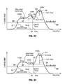
- FIG. 34D is a graph illustrating a signal generated by one of the proximity sensors in response to movement of the finger as shown in FIGS. 34A-34C ;
- FIG. 35 is a perspective cross-sectional view of a vehicle overhead console having a proximity switch assembly employing a groove between adjacent sensors, according to another embodiment
- FIG. 36 is a top view of the overhead console and switch assembly shown in FIG. 35 with the sensors, depressions and grooves shown in hidden lines;
- FIG. 37A is a cross-sectional view of the proximity switch assembly shown in FIG. 35 , and a user's finger shown in a first position, according to another embodiment
- FIG. 37B is a cross-sectional view of the proximity switch assembly of FIG. 37A further illustrating the user's finger in a second position;
- FIG. 37C is a cross-sectional view of the proximity switch assembly as seen in FIG. 37A further illustrating the user's finger in a third position;
- FIG. 37D is a cross-sectional view of the proximity switch assembly as seen in FIG. 37A further illustrating the user's finger in a fourth position;
- FIG. 37E is a graph illustrating two signals generated by two of the sensors in response to movement of the finger as shown in FIGS. 37A-37D ;
- FIG. 38 is a cross-sectional view of a proximity switch assembly employing a pliable cover material having a depression and an elevated region in the pliable material above each depression, according to a further embodiment.
- an automotive vehicle 10 having a passenger compartment and a switch assembly 20 employing a plurality of proximity switches 22 having switch activation monitoring and determination, according to one embodiment.
- the vehicle 10 generally includes an overhead console 12 assembled to the headliner on the underside of the roof or ceiling at the top of the vehicle passenger compartment, generally above the front passenger seating area.
- the switch assembly 20 has a plurality of proximity switches 22 arranged close to one another in the overhead console 12 , according to one embodiment.
- the various proximity switches 22 may control any of a number of vehicle devices and functions, such as controlling movement of a sunroof or moonroof 16 , controlling movement of a moonroof shade 18 , controlling activation of one or more lighting devices such as interior map/reading and dome lights 30 , and various other devices and functions.
- the proximity switches 22 may be located elsewhere on the vehicle 10 , such as in the dash panel, on other consoles such as a center console, integrated into a touch screen display 14 for a radio or infotainment system such as a navigation and/or audio display, or located elsewhere onboard the vehicle 10 according to various vehicle applications.
- Each proximity switch 22 includes at least one proximity sensor that provides a sense activation field to sense contact or close proximity (e.g., within one millimeter) of a user in relation to the one or more proximity sensors, such as a swiping motion by a user's finger.
- the sense activation field of each proximity switch 22 is a capacitive field in the exemplary embodiment and the user's finger has electrical conductivity and dielectric properties that cause a change or disturbance in the sense activation field as should be evident to those skilled in the art.
- proximity sensors can be used, such as, but not limited to, inductive sensors, optical sensors, temperatures sensors, resistive sensors, the like, or a combination thereof.
- Exemplary proximity sensors are described in the Apr. 9, 2009, ATMEL® Touch Sensors Design Guide, 10620 D-AT42-04/09, the entire reference hereby being incorporated herein by reference.
- the proximity switches 22 shown in FIGS. 1 and 2 each provide control of a vehicle component or device or provide a designated control function.
- One or more of the proximity switches 22 may be dedicated to controlling movement of a sunroof or moonroof 16 so as to cause the moonroof 16 to move in an open or closed direction, tilt the moonroof, or stop movement of the moonroof based upon a control algorithm.
- One or more other proximity switches 22 may be dedicated to controlling movement of a moonroof shade 18 between open and closed positions. Each of the moonroof 16 and shade 18 may be actuated by an electric motor in response to actuation of the corresponding proximity switch 22 .
- proximity switches 22 may be dedicated to controlling other devices, such as turning an interior map/reading light 30 on, turning an interior map/reading light 30 off, turning a dome lamp on or off, unlocking a trunk, opening a rear hatch, or defeating a door light switch. Additional controls via the proximity switches 22 may include actuating door power windows up and down. Various other vehicle controls may be controlled by way of the proximity switches 22 described herein.
- each proximity switch 22 includes one or more proximity sensors 24 for generating a sense activation field.
- each of the proximity sensors 24 may be formed by printing conductive ink onto the top surface of the polymeric overhead console 12 .
- FIG. 4 One example of a printed ink proximity sensor 24 is shown in FIG. 4 generally having a drive electrode 26 and a receive electrode 28 each having interdigitated fingers for generating a capacitive field 32 .
- each of the proximity sensors 24 may be otherwise formed such as by assembling a preformed conductive circuit trace onto a substrate according to other embodiments.
- the drive electrode 26 receives square wave drive pulses applied at voltage V I .
- the receive electrode 28 has an output for generating an output voltage V O . It should be appreciated that the electrodes 26 and 28 may be arranged in various other configurations for generating the capacitive field as the activation field 32 .
- the drive electrode 26 of each proximity sensor 24 is applied with voltage input V I as square wave pulses having a charge pulse cycle sufficient to charge the receive electrode 28 to a desired voltage.
- the receive electrode 28 thereby serve as a measurement electrode.
- adjacent sense activation fields 32 generated by adjacent proximity switches 22 overlap slightly, however, overlap may not exist according to other embodiments.
- the proximity switch assembly 20 detects the disturbance caused by the finger 34 to the activation field 32 and determines whether the disturbance is sufficient to activate the corresponding proximity switch 22 .
- the disturbance of the activation field 32 is detected by processing the charge pulse signal associated with the corresponding signal channel.
- the proximity switch assembly 20 detects the disturbance of both contacted activation fields 32 via separate signal channels.
- Each proximity switch 22 has its own dedicated signal channel generating charge pulse counts which is processed as discussed herein.
- the proximity switch assembly 20 is illustrated according to one embodiment.
- a plurality of proximity sensors 24 are shown providing inputs to a controller 40 , such as a microcontroller.
- the controller 40 may include control circuitry, such as a microprocessor 42 and memory 48 .
- the control circuitry may include sense control circuitry processing the activation field of each sensor 22 to sense user activation of the corresponding switch by comparing the activation field signal to one or more thresholds pursuant to one or more control routines. It should be appreciated that other analog and/or digital control circuitry may be employed to process each activation field, determine user activation, and initiate an action.
- the controller 40 may employ a QMatrix acquisition method available by ATMEL®, according to one embodiment.
- the ATMEL acquisition method employs a WINDOWS® host C/C++ compiler and debugger WinAVR to simplify development and testing the utility Hawkeye that allows monitoring in real-time the internal state of critical variables in the software as well as collecting logs of data for post-processing.
- the controller 40 provides an output signal to one or more devices that are configured to perform dedicated actions responsive to correct activation of a proximity switch.
- the one or more devices may include a moonroof 16 having a motor to move the moonroof panel between open and closed and tilt positions, a moonroof shade 18 that moves between open and closed positions, and lighting devices 30 that may be turned on and off.
- Other devices may be controlled such as a radio for performing on and off functions, volume control, scanning, and other types of devices for performing other dedicated functions.
- One of the proximity switches 22 may be dedicated to actuating the moonroof closed, another proximity switch 22 may be dedicated to actuating the moonroof open, and a further switch 22 may be dedicated to actuating the moonroof to a tilt position, all of which would cause a motor to move the moonroof to a desired position.
- the moonroof shade 18 may be opened in response to one proximity switch 22 and may be closed responsive to another proximity switch 22 .
- the controller 40 is further shown having an analog to digital (A/D) comparator 44 coupled to the microprocessor 42 .
- the A/D comparator 44 receives the voltage output V O from each of the proximity switches 22 , converts the analog signal to a digital signal, and provides the digital signal to the microprocessor 42 .
- controller 40 includes a pulse counter 46 coupled to the microprocessor 42 .
- the pulse counter 46 counts the charge signal pulses that are applied to each drive electrode of each proximity sensor, performs a count of the pulses needed to charge the capacitor until the voltage output V O reaches a predetermined voltage, and provides the count to the microprocessor 42 .
- the pulse count is indicative of the change in capacitance of the corresponding capacitive sensor.
- the controller 40 is further shown communicating with a pulse width modulated drive buffer 15 .
- the controller 40 provides a pulse width modulated signal to the pulse width modulated drive buffer 15 to generate a square wave pulse train V I which is applied to each drive electrode of each proximity sensor/switch 22 .
- the controller 40 processes a control routine 100 stored in memory to monitor and make a determination as to activation of one of the proximity switches.
- the change in sensor charge pulse counts shown as ⁇ Sensor Count for a plurality of signal channels associated with a plurality of proximity switches 22 is illustrated according to various examples.
- the change in sensor charge pulse count is the difference between an initialized referenced count value without any finger or other object present in the activation field and the corresponding sensor reading.
- the user's finger enters the activation fields 32 associated with each of three proximity switches 22 , generally one sense activation field at a time with overlap between adjacent activation fields 32 as the user's finger moves across the array of switches.
- Channel 1 is the change ( ⁇ ) in sensor charge pulse count associated with a first capacitive sensor 24
- channel 2 is the change in sensor charge pulse count associated with the adjacent second capacitive sensor 24
- channel 3 is the change in sensor charge pulse count associated with the third capacitive sensor 24 adjacent to the second capacitive sensor.
- the proximity sensors 24 are capacitive sensors. When a user's finger is in contact with or close proximity of a sensor 24 , the finger alters the capacitance measured at the corresponding sensor 24 . The capacitance is in parallel to the untouched sensor pad parasitic capacitance, and as such, measures as an offset.
- each sensor is excited with a train of voltage pulses via pulse width modulation (PWM) electronics until the sensor is charged up to a set voltage potential.
- PWM pulse width modulation
- Such an acquisition method charges the receive electrode 28 to a known voltage potential.
- the cycle is repeated until the voltage across the measurement capacitor reaches a predetermined voltage.
- Placing a user's finger on the touch surface of the switch 24 introduces external capacitance that increases the amount of charge transferred each cycle, thereby reducing the total number of cycles required for the measurement capacitance to reach the predetermined voltage.
- the user's finger causes the change in sensor charge pulse count to increase since this value is based on the initialized reference count minus the sensor reading.
- the proximity switch assembly 20 is able to recognize the user's hand motion when the hand, particularly a finger, is in close proximity to the proximity switches 22 , to discriminate whether the intent of the user is to activate a switch 22 , explore for a specific switch button while focusing on higher priority tasks, such as driving, or is the result of a task such as adjusting the rearview mirror that has nothing to do with actuation of a proximity switch 22 .
- the proximity switch assembly 20 may operate in an exploration or hunting mode which enables the user to explore the keypads or buttons by passing or sliding a finger in close proximity to the switches without triggering an activation of a switch until the user's intent is determined.
- the proximity switch assembly 20 monitors amplitude of a signal generated in response to the activation field, determines a differential change in the generated signal, and generates an activation output when the differential signal exceeds a threshold.
- exploration of the proximity switch assembly 20 is allowed, such that users are free to explore the switch interface pad with their fingers without inadvertently triggering an event, the interface response time is fast, activation happens when the finger contacts a surface panel, and inadvertent activation of the switch is prevented or reduced.
- an entry ramp slope method may be used to determine whether the operator intends to press a button or explore the interface based on the slope of the entry ramp in signal 50 A of the channel 1 signal rising from point 52 where signal 50 A crosses the level active (LVL_ACTIVE) count up to point 54 where signal 50 A crosses the level threshold (LVL_THRESHOLD) count, according to one embodiment.
- the slope of the entry ramp is the differential change in the generated signal between points 52 and 54 which occurred during the time period between times t th and t ac .
- level active generally changes only as the presence of gloves is detected, but is otherwise a constant
- the slope can be calculated as just the time expired to cross from level active to level threshold referred to as t active2threshold which is the difference between time t th and t ac .
- a direct push on a switch pad typically may occur in a time period referred to t directpush in the range of about 40 to 60 milliseconds. If the time t active2threshold is less than or equal to the direct push time t directpush , then activation of the switch is determined to occur. Otherwise, the switch is determined to be in an exploration mode.
- the slope of the entry ramp may be computed as the difference in time from the time t ac at point 52 to time t pk to reach the peak count value at point 56 , referred to as time t active2peak .
- the time t active2peak may be compared to a direct push peak, referred to as t direct _ push _ pk which may have a value of 100 milliseconds according to one embodiment. If time t active2peak is less than or equal to the t direct _ push _ pk activation of the switch is determined to occur. Otherwise, the switch assembly operates in an exploration mode.
- the channel 1 signal is shown increasing as the capacitance disturbance increases rising quickly from point 52 to peak value at point 56 .
- the proximity switch assembly 20 determines the slope of the entry ramp as either time period t active2threshold or t active2peak for the signal to increase from the first threshold point 52 to either the second threshold at point 54 or the peak threshold at point 56 .
- the slope or differential change in the generated signal is then used for comparison with a representative direct push threshold t direct _ push or t direct _ push _ pk to determine activation of the proximity switch. Specifically, when time t active2peak is less than the t direct _ push or t active2threshold is less than t direct _ push , activation of the switch is determined. Otherwise, the switch assembly remains in the exploration mode.
- FIG. 7 one example of a sliding/exploration motion across two switches is illustrated as the finger passes or slides through the activation field of two adjacent proximity sensors shown as signal channel 1 labeled 50 A and signal channel 2 labeled 50 B.
- signal channel 1 labeled 50 A As the user's finger approaches a first switch, the finger enters the activation field associated with the first switch sensor causing the change in sensor count on signal 50 A to increase at a slower rate such that a lessened differential change in the generated signal is determined.
- the profile of signal channel 1 experiences a change in time t active2peak that is not less than or equal to t direct _ push , thereby resulting in entering the hunting or exploration mode.
- the t active2threshold is indicative of a slow differential change in the generated signal, no activation of the switch button is initiated, according to one embodiment.
- the time t active2peak is not less than or equal to t direct _ push _ pk , indicative of a slow differential change in a generated signal, no activation is initiated, according to another embodiment.
- the second signal channel labeled 50 B is shown as becoming the maximum signal at transition point 58 and has a rising change in ⁇ sensor count with a differential change in the signal similar to that of signal 50 A.
- the first and second channels 50 A and 50 B reflect a sliding motion of the finger across two capacitive sensors in the exploration mode resulting in no activation of either switch.
- t active2threshold or t active2peak a decision can be made to activate or not a proximity switch as its capacitance level reaches the signal peak.
- a slow direct push motion such as shown in FIG. 8
- additional processing may be employed to make sure that no activation is intended.
- the signal channel 1 identified as signal 50 A is shown more slowly rising during either time period t active2threshold or t active2peak which would result in the entering of the exploration mode.
- t active2threshold greater than t direct _ push if the channel failing the condition was the first signal channel entering the exploration mode and it is still the maximum channel (channel with the highest intensity) as its capacitance drops below LVL_KEYUP_Threshold at point 60 , then activation of the switch is initiated.
- a fast motion of a user's finger across the proximity switch assembly is illustrated with no activation of the switches.
- the relatively large differential change in the generated signal for channels 1 and 2 are detected, for both channels 1 and 2 shown by lines 50 A and 50 B, respectively.
- the switch assembly employs a delayed time period to delay activation of a decision until the transition point 58 at which the second signal channel 50 B rises above the first signal channel 50 A.
- the time delay could be set equal to time threshold t direct _ push _ pk according to one embodiment.
- the exploration mode may be entered automatically, according to one embodiment. As a result, once an inadvertent actuation is detected and rejected, more caution may be applied for a period of time in the exploration mode.
- Another way to allow an operator to enter the exploration mode is to use one or more properly marked and/or textured areas or pads on the switch panel surface associated with the dedicated proximity switches with the function of signaling the proximity switch assembly of the intent of the operator to blindly explore.
- the one or more exploration engagement pads may be located in an easy to reach location not likely to generate activity with other signal channels.
- an unmarked, larger exploration engagement pad may be employed surrounding the entire switch interface. Such an exploration pad would likely be encountered first as the operator's hand slides across the trim in the overhead console looking for a landmark from which to start blind exploration of the proximity switch assembly.
- the assembly determines whether an increase in the change in sensor count is a switch activation or the result of an exploration motion, the assembly proceeds to determine whether and how the exploration motion should terminate or not in an activation of proximity switch.
- the proximity switch assembly looks for a stable press on a switch button for at least a predetermined amount of time.
- the predetermined amount of time is equal to or greater than 50 milliseconds, and more preferably about 80 milliseconds. Examples of the switch assembly operation employing a stable time methodology is illustrated in FIGS. 10-13 .
- the exploration of three proximity switches corresponding to signal channels 1-3 labeled as signals 50 A- 50 C, respectively, is illustrated while a finger slides across first and second switches in the exploration mode and then activates the third switch associated with signal channel 3.
- the signal on line 50 A for channel 1 begins as the maximum signal value until channel 2 on line 50 B becomes the maximum value and finally channel 3 becomes a maximum value.
- Signal channel 3 is shown having a stable change in sensor count near the peak value for a sufficient time period t stable such as 80 milliseconds which is sufficient to initiate activation of the corresponding proximity switch.
- the stable level method activates the switch after the level on the switch is bound in a tight range for at least the time period t stable . This allows the operator to explore the various proximity switches and to activate a desired switch once it is found by maintaining position of the user's finger in proximity to the switch for a stable period of time t stable .
- the third signal channel on line 50 C has a change in sensor count that has a stable condition on the descent of the signal.
- the change in sensor count for the third channel exceeds the level threshold and has a stable press detected for the time period t stable such that activation of the third switch is determined.
- the proximity switch assembly may employ a virtual button method which looks for an initial peak value of change in sensor count while in the exploration mode followed by an additional sustained increase in the change in sensor count to make a determination to activate the switch as shown in FIGS. 12 and 13 .
- the third signal channel on line 50 C rises up to an initial peak value and then further increases by a change in sensor count C vb . This is equivalent to a user's finger gently brushing the surface of the switch assembly as it slides across the switch assembly, reaching the desired button, and then pressing down on the virtual mechanical switch such that the user's finger presses on the switch contact surface and increases the amount of volume of the finger closer to the switch.
- the increase in capacitance is caused by the increased surface of the fingertip as it is compressed on the pad surface.
- the increased capacitance may occur immediately following detection of a peak value shown in FIG. 12 or may occur following a decline in the change in sensor count as shown in FIG. 13 .
- the proximity switch assembly detects an initial peak value followed by a further increased change in sensor count indicated by capacitance C vb at a stable level or a stable time period t stable .
- a stable level of detection generally means no change in sensor count value absent noise or a small change in sensor count value absent noise which can be predetermined during calibration.
- both the stable value method and the virtual button method can be active at the same time.
- the stable time t stable can be relaxed to be longer, such as one second, since the operator can always trigger the button using the virtual button method without waiting for the stable press time-out.
- the proximity switch assembly may further employ robust noise rejection to prevent annoying inadvertent actuations. For example, with an overhead console, accidental opening and closing of the moonroof should be avoided. Too much noise rejection may end up rejecting intended activations, which should be avoided.
- One approach to rejecting noise is to look at whether multiple adjacent channels are reporting simultaneous triggering events and, if so, selecting the signal channel with the highest signal and activating it, thereby ignoring all other signal channels until the release of the select signal channel.
- the proximity switch assembly 20 may include a signature noise rejection method based on two parameters, namely a signature parameter that is the ratio between the channel between the highest intensity (max_channel) and the overall cumulative level (sum_channel), and the dac parameter which is the number of channels that are at least a certain ratio of the max_channel.
- a signature parameter that is the ratio between the channel between the highest intensity (max_channel) and the overall cumulative level (sum_channel)
- the dac parameter which is the number of channels that are at least a certain ratio of the max_channel.
- the dac ⁇ dac 0.5.
- the signature parameter may be defined by the following equation:
- the channel generally must be clean, i.e., the signature must be higher than a predefined threshold.
- the signature may have the following equation:
- a noise rejection triggers hunting mode may be employed.
- the hunting or exploration mode should be automatically engaged.
- a user may reach with all fingers extended looking to establish a reference frame from which to start hunting. This may trigger multiple channels at the same time, thereby resulting in a poor signature.
- a state diagram is shown for the proximity switch assembly 20 in a state machine implementation, according to one embodiment.
- the state machine implementation is shown having five states including SW_NONE state 70 , SW_ACTIVE state 72 , SW_THRESHOLD state 74 , SW_HUNTING state 76 and SWITCH_ACTIVATED state 78 .
- the SW_NONE state 70 is the state in which there is no sensor activity detected.
- the SW_ACTIVE state is the state in which some activity is detected by the sensor, but not enough to trigger activation of the switch at that point in time.
- the SW_THRESHOLD state is the state in which activity as determined by the sensor is high enough to warrant activation, hunting/exploration, or casual motion of the switch assembly.
- the SW_HUNTING state 76 is entered when the activity pattern as determined by the switch assembly is compatible with the exploration/hunting interaction.
- the SWITCH_ACTIVATED state 78 is the state in which activation of a switch has been identified. In the SWITCH_ACTIVATED state 78 , the switch button will remain active and no other selection will be possible until the corresponding switch is released.
- the state of the proximity switch assembly 20 changes depending upon the detection and processing of the sensed signals.
- the system 20 may advance to the SW_ACTIVE state 72 when some activity is detected by one or more sensors. If enough activity to warrant either activation, hunting or casual motion is detected, the system 20 may proceed directly to the SW_THRESHOLD state 74 .
- the system 20 may proceed to the SW_HUNTING state 76 when a pattern indicative of exploration is detected or may proceed directly to switch activated state 78 .
- an activation of the switch may be detected to change to the SWITCH_ACTIVATED state 78 . If the signal is rejected and inadvertent action is detected, the system 20 may return to the SW_NONE state 70 .
- Method 100 begins at step 102 and proceeds to step 104 to perform an initial calibration which may be performed once.
- the calibrated signal channel values are computed from raw channel data and calibrated reference values by subtracting the reference value from the raw data in step 106 .
- step 108 from all signal channel sensor readings, the highest count value referenced as max_channel and the sum of all channel sensor readings referred to as sum_channel are calculated. In addition, the number of active channels is determined.
- method 100 calculates the recent range of the max_channel and the sum_channel to determine later whether motion is in progress or not.
- method 100 proceeds to decision step 112 to determine if any of the switches are active. If no switch is active, method 100 proceeds to step 114 to perform an online real-time calibration. Otherwise, method 116 processes the switch release at step 116 . Accordingly, if a switch was already active, then method 100 proceeds to a module where it waits and locks all activity until its release.
- method 100 proceeds to decision step 118 to determine if there is any channel lockout indicative of recent activation and, if so, proceeds to step 120 to decrease the channel lockout timer. If there are no channel lockouts detected, method 100 proceeds to decision step 122 to look for a new max_channel. If the current max_channel has changed such that there is a new max_channel, method 100 proceeds to step 124 to reset the max_channel, sum the ranges, and set the threshold levels. Thus, if a new max_channel is identified, the method resets the recent signal ranges, and updates, if needed, the hunting/exploration parameters.
- step 126 process the max_channel naked (no glove) finger status. This may include processing the logic between the various states as shown in the state diagram of FIG. 14 .
- method 100 proceeds to decision step 128 to determine if any switch is active. If no switch activation is detected, method 100 proceeds to step 130 to detect a possible glove presence on the user's hand. The presence of a glove may be detected based on a reduced change in capacitance count value. Method 100 then proceeds to step 132 to update the past history of the max_channel and sum_channel. The index of the active switch, if any, is then output to the software hardware module at step 134 before ending at step 136 .
- a process switch release routine is activated which is shown in FIG. 16 .
- the process switch release routine 116 begins at step 140 and proceeds to decision step 142 to determine if the active channel is less than LVL_RELEASE and, if so, ends at step 152 . If the active channel is less than the LVL_RELEASE then routine 116 proceeds to decision step 144 to determine if the LVL_DELTA_THRESHOLD is greater than 0 and, if not, proceeds to step 146 to raise the threshold level if the signal is stronger. This may be achieved by decreasing LVL_DELTA_THRESHOLD. Step 146 also sets the threshold, release and active levels.
- Routine 116 then proceeds to step 148 to reset the channel max and sum history timer for long stable signal hunting/exploration parameters.
- the switch status is set equal to SW_NONE at step 150 before ending at step 152 .
- LVL_RELEASE is an adaptive threshold that will change as glove interaction is detected.
- the switch button is released, all internal parameters are reset and a lockout timer is started to prevent further activations before a certain waiting time has elapsed, such as 100 milliseconds.
- the threshold levels are adapted in function of the presence of gloves or not.
- Routine 200 begins at step 202 to process the SW_NONE state, and then proceeds to decision step 204 to determine if the max_channel is greater than LVL_ACTIVE. If the max_channel is greater than LVL_ACTIVE, then the proximity switch assembly changes state from SW_NONE state to SW_ACTIVE state and ends at step 210 . If the max_channel is not greater than LVL_ACTIVE, the routine 200 checks for whether to reset the hunting flag at step 208 prior to ending at step 210 .
- the status changes from SW_NONE state to SW_ACTIVE state when the max_channel triggers above LVL_ACTIVE. If the channels stays below this level, after a certain waiting period, the hunting flag, if set, gets reset to no hunting, which is one way of departing from the hunting mode.
- Method 220 begins at step 222 and proceeds to decision step 224 . If max_channel is not greater than LVL_THRESHOLD, then method 220 proceeds to step 226 to determine if the max_channel is less than LVL_ACTIVE and, if so, proceeds to step 228 to change the switch status to SW_NONE. Accordingly, the status of the state machine moves from the SW_ACTIVE state to SW_NONE state when the max_channel signal drops below LVL_ACTIVE.
- a delta value may also be subtracted from LVL_ACTIVE to introduce some hysteresis. If the max_channel is greater than the LVL_THRESHOLD, then routine 220 proceeds to decision step 230 to determine if a recent threshold event or a glove has been detected and, if so, sets the hunting on flag equal to true at step 232 . At step 234 , method 220 switches the status to SW_THRESHOLD state before ending at step 236 . Thus, if the max_channel triggers above the LVL_THRESHOLD, the status changes to SW_THRESHOLD state. If gloves are detected or a previous threshold event that did not result in activation was recently detected, then the hunting/exploration mode may be entered automatically.
- Method 240 begins at step 242 to process the SW_THRESHOLD state and proceeds to decision block 244 to determine if the signal is stable or if the signal channel is at a peak and, if not, ends at step 256 . If either the signal is stable or the signal channel is at a peak, then method 240 proceeds to decision step 246 to determine if the hunting or exploration mode is active and, if so, skips to step 250 .
- method 240 proceeds to decision step 248 to determine if the signal channel is clean and fast active is greater than a threshold and, if so, sets the switch active equal to the maximum channel at step 250 .
- Method 240 proceeds to decision block 252 to determine if there is a switch active and, if so, ends at step 256 . If there is no switch active, method 240 proceeds to step 254 to initialize the hunting variables SWITCH_STATUS set equal to SWITCH_HUNTING and PEAK_MAX_BASE equal to MAX_CHANNELS, prior to ending at step 256 .
- SW_ACTIVE to SW_THRESHOLD was a less than a threshold such as 16 milliseconds, and the signature of noise rejection method indicates it as a valid triggering event, then the state is changed to SWITCH_ACTIVE and the process is transferred to the PROCESS_SWITCH_RELEASE module, otherwise the hunting flag is set equal to true. If the delayed activation method is employed instead of immediately activating the switch, the state is changed to SW_DELAYED_ACTIVATION where a delay is enforced at the end of which, if the current MAX_CHANNEL index has not changed, the button is activated.
- the method 260 begins at step 262 to process the SW_HUNTING state and proceeds to decision step 264 to determine if the MAX_CHANNEL has dropped below the LVL_KEYUP_THRESHOLD and, if so, sets the MAX_PEAK_BASE equal to MIN(MAX_PEAK_BASE, MAX_CHANNEL) at step 272 . If the MAX_CHANNEL has dropped below the LVL_KEYUP_THRESHOLD, then method 260 proceeds to step 266 to employ the first channel triggering hunting method to check whether the event should trigger the button activation.
- method 260 determines if the first and only channel is traversed and the signal is clean. If so, method 260 sets the switch active equal to the maximum channel at step 270 before ending at step 282 . If the first and only channel is not traversed or if the signal is not clean, method 260 proceeds to step 268 to give up and determine an inadvertent actuation and to set the SWITCH_STATUS equal to SW_NONE state before ending at step 282 .
- method 260 proceeds to decision step 274 to determine if the channel clicked. This can be determined by whether MAX_CHANNEL is greater than MAX_PEAK_BASE plus delta. If the channel has clicked, method 260 proceeds to decision step 276 to determine if the signal is stable and clean and, if so, sets the switch active state to the maximum channel at step 280 before ending at step 282 . If the channel has not clicked, method 260 proceeds to decision step 278 to see if the signal is long, stable and clean, and if so, proceeds to step 280 to set the switch active equal to the maximum channel before ending at step 282 .
- the proximity switch assembly 20 may include a virtual button mode, according to another embodiment. Referring to FIGS. 21-27 , the proximity switch assembly having a virtual button mode and a method of activating the proximity switch with the virtual button mode is shown therein, according to this embodiment.
- the proximity switch assembly may include one or more proximity switches each providing a sense activation field and control circuitry for controlling the activation field of each proximity switch to sense activation.
- the control circuitry monitors signals indicative of the activation fields, determines a first stable amplitude of the signal for a time period, determines a subsequent second stable amplitude of the signal for the time period, and generates an activation output when the second stable signal exceeds the first stable signal by a known amount.
- the method may be employed by the proximity switch assembly and includes the steps of generating an activation field associated with each of one or more of a plurality of proximity sensors, and monitoring a signal indicative of each associated activation field.
- the method also includes the steps of determining a first amplitude when the signal is stable for a minimum time period, and determining a second amplitude when the signal is stable for the minimum time period.
- the method further includes the step of generating an activation output when the second amplitude exceeds the first amplitude by a known amount.
- FIG. 21 the exploration and activation of a proximity switch is shown for one of the signal channels labeled as signal 50 as a user's finger slides across the corresponding switch, enters an exploration mode, and proceeds to activate the switch in the virtual button mode.
- the user's finger may explore a plurality of capacitive switches as illustrated in FIGS. 10-12 in which signals associated with each of the corresponding signal channels are generated as the finger passes through the activation field of each channel.
- a plurality of signal channels may be processed at the same time and the maximum signal channel may be processed to determine activation of the corresponding proximity switch.
- a single signal channel associated with one switch is shown, however, a plurality of signal channels could be processed.
- the signal 50 associated with one of the signal channels is shown in FIG. 21 rising up to a threshold active level 320 at point 300 at which point the signal enters the exploration mode.
- the signal 50 thereafter continues to rise and reaches a first amplitude at which point the signal is stable for a minimum time period, shown as Tstable which is shown at point 302 .
- Tstable a minimum time period
- the signal 50 enters the virtual button mode and establishes a first base value Cbase which is the delta signal count at point 302 .
- the virtual button mode establishes an incremental activation threshold as a function of the base value Cbase multiplied by a constant K vb .
- the activation threshold for determining an activation may be represented by: (1+K vb ) ⁇ Cbase, wherein K vb is a constant greater than zero.
- the virtual button mode continues to monitor the signal 50 to determine when it reaches a second stable amplitude for the minimum time period Tstable which occurs at point 304 .
- the virtual button mode compares the second stable amplitude to the first stable amplitude and determines if the second amplitude exceeds the first amplitude by the known amount of K vb ⁇ Cbase. If the second amplitude exceeds the first amplitude by the known amount, an activation output for the proximity switch is then generated.
- a stable signal amplitude must be maintained by the signal channel for at least a minimum time period Tstable prior to entering the virtual button mode or determining activation of the switch.
- the sensor value as it enters the virtual button mode is recorded as Cbase.
- the method monitors for when a subsequent stable signal amplitude is achieved again prior to a time-out period. If a stable signal amplitude is achieved again prior to the time-out period expiring with a delta count value greater than a desired percentage, such as 12.5 percent of the prior recorded Cbase, then activation is triggered.
- a percentage delta signal count increase of at least 10 percent is provided by K vb ⁇ Cbase.
- the multiplier K vb is a factor of at least 0.1 or at least 10 percent of the Cbase value, according to one embodiment. According to another embodiment, the multiplier K vb is set at about 0.125 which equivalent to 12.5 percent.
- the stable time period Tstable may be set to a time of at least 50 milliseconds, according to one embodiment. According to another embodiment, the stable time period Tstable may be set in the range of 50 to 100 milliseconds.
- the stable amplitude may be determined by the signal amplitude being substantially stable in a range within twice the size of estimated noise on the signal according to one embodiment, or within 2.5 to 5.0 percent of the signal level, according to another embodiment or a combination of twice the estimated noise of the signal added to 2.5 to 5.0 percent of the signal level, according to a further embodiment.
- a signal 50 for a signal channel associated with a proximity switch entering the exploration mode at point 300 and proceeding to a reach a stable first amplitude when the stable signal amplitude exists for a minimum time period Tstable at point 302 in which the virtual button mode is entered.
- the Cbase value is determined.
- the signal 50 is shown dropping and again rising to a second amplitude when the signal is stable for the minimum time period Tstable at point 306 .
- the second amplitude at point 306 does not exceed the base value Cbase of the signal at point 302 by the known amount of K vb ⁇ Cbase, and as a result does not generate an activation output for the switch.
- a signal 50 associated with a signal channel is illustrated entering the exploration mode at point 300 and proceeding to reach a first amplitude for a stable time period Tstable at point 302 in which the virtual button mode is entered and Cbase is determined. Thereafter, the signal 50 continues to rise to a second amplitude that is stable for the minimum time period Tstable at point 308 . However, at point 308 , the second amplitude does not exceed the base value Cbase of the signal established at the first amplitude at point 302 by the known amount of K vb ⁇ Cbase, so the proximity switch assembly does not trigger a switch output.
- a new updated base value is generated for Cbase at point 308 and is used to determine the known amount for comparison with the next stable amplitude.
- Signal 50 is shown dropping and then rising to a third amplitude that is stable for the minimum time period Tstable at point 310 .
- the third amplitude exceeds the second amplitude by more than the known amount K vb ⁇ Cbase such that an activation output for the switch is generated.
- FIG. 24 another example of a signal 50 is illustrated entering the exploration mode at point 300 and continuing to rise to a first amplitude that is stable for a minimum time period Tstable at point 302 in which the virtual button mode is entered and Cbase is determined. Thereafter, the signal 50 is shown dropping to a second amplitude that is stable for the minimum time period Tstable at point 312 . At point 312 , the second amplitude does not exceed the first amplitude by the known amount of K vb ⁇ Cbase such that a trigger of the signal is not generated. However, an updated base value Cbase is generated at point 312 . Thereafter, signal 50 continues to rise to a third amplitude that is stable for the minimum time period Tstable at point 310 . The third amplitude exceeds the second amplitude by the known amount K vb ⁇ Cbase, such that a trigger or activation output for the switch is generated.
- FIG. 25 another example of a signal 50 for a signal channel is shown entering the exploration mode at point 300 and proceeding to reach a first amplitude that is stable for the minimum time period Tstable at point 302 and therefore enters the virtual button mode and determines Cbase.
- signal 50 continues to rise to a second amplitude that is stable for the time period Tstable at point 308 .
- the second amplitude does not exceed the first amplitude by the known amount such that a trigger of the switch is not generated at this point.
- signal 50 is shown dropping to point 314 and in the process of doing so, a reset timer times out since the last stable amplitude was received as shown by time Treset.
- the virtual button mode is exited and the exploration mode is entered once the virtual button mode is exited.
- the prior determined Cbase is no longer valid.
- signal 50 is shown rising to a third amplitude that is stable for the minimum time period Tstable at point 316 .
- the third amplitude establishes an updated Cbase which is used for determining future activations of the switch.
- the signal 50 is further shown dropping below the threshold active value 320 , in which case, the virtual button mode is exited without any activations.
- FIGS. 26 and 27 A method of activating a proximity switch with a virtual button mode using the proximity switch assembly is illustrated in FIGS. 26 and 27 .
- method 400 begins at step 402 and proceeds to acquire all signal channels associated with all proximity switches at step 404 .
- Method 400 proceeds to decision block 406 to determine if the state is set in the ACTIVE state and, if so, checks for a release of the switch at step 414 before ending at step 416 . If the state is not set to the ACTIVE state, method 400 proceeds to step 408 to find the maximum channel (CHT). Next, once the maximum channel has been found, routine 400 proceeds to step 410 to process the maximum channel (CHT) virtual-button method before ending at step 416 .
- CHT maximum channel
- method 400 may include an optional step 412 for also processing the maximum channel signal using a tapping method to detect a user tapping on a proximity switch so as to generate an activation output.
- the process maximum channel virtual-button method 410 shown in FIG. 27 begins at step 420 and proceeds to step 422 to input the maximum channel signal. Hence, the maximum signal channel associated with one of the proximity switches is processed to determine the virtual button mode state and activation of the switch.
- method 410 determines if the switch is set to the virtual button mode state and, if so, proceeds to decision step 426 to determine if the signal channel value is less than the active threshold. If the signal channel is less than the active threshold, method 410 proceeds to step 428 to set the state equal to NONE and returns to the beginning.
- method 410 proceeds to decision step 430 to determine if the signal has a stable first amplitude for a time period greater than the stable time period Tstable. If the stable signal channel at the first amplitude is stable for a time period greater than Tstable, method 410 proceeds to decision step 432 to determine if the signal channel is not stable for a time period exceeding the reset time period Treset and, if not, returns to step 422 . If the signal channel is not stable for a time period exceeding the reset time period Treset, method 410 proceeds to set the state equal to the exploration/hunting state and ends at step 460 .
- method 410 proceeds to decision step 436 to determine if the signal Ch(t) is greater than Cbase by a known amount defined by K vb ⁇ C base and, if so, sets the switch state to active so as to generate an activation output before ending at step 460 . If the signal does not exceed Cbase by the known amount of K vb ⁇ C base , method 410 proceeds to set the new Cbase value at the current stable signal amplitude at step 440 , before ending at step 460 .
- method 410 proceeds to decision step 442 to determine if the state is set to the exploration state and, if so, proceeds to decision step 444 to determine if the signal is greater than the active threshold and, if not, sets the state equal to the NONE state and ends at step 460 . If the signal is greater than the active threshold, method 410 proceeds to decision step 448 to determine if the signal is stable at an amplitude for a time period exceeding the minimum time period Tstable and, if not, ends at step 460 .
- step 410 proceeds to step 450 to set the state for the switch to the virtual button state and to establish the new Cbase value for the signal channel at step 450 before ending at step 460 .
- method 410 proceeds to decision step 452 to determine if the signal is greater than the active threshold and, if not, ends at step 460 . If the signal is greater than the active threshold, method 410 proceeds to decision step 454 to set the state to the exploration/hunting state before ending at step 460 .
- the proximity switch assembly having the virtual button method 410 advantageously provides for enhanced virtual button switch activation detection and improved rejection of unintended activations.
- Method 410 may advantageously detect an activation of a switch while rejecting unintended activations which may be detected when a finger explores the switch assembly and reverses direction or in which the user's finger is wearing a glove.
- the enhanced activation detection advantageously provides for enhanced proximity switch assembly.
- the determination routine advantageously determines activation of the proximity switches.
- the routine advantageously allows for a user to explore the proximity switch pads which can be particularly useful in an automotive application where driver distraction can be avoided.
- the proximity switch assembly 20 may include a pliable material overlaying the proximity sensor and the control circuitry may activate a proximity switch based on a signal generated by the sensor in relation to a threshold when a user's finger depresses the pliable material, according to a further embodiment.
- the proximity switch assembly 20 may operate in the virtual button mode and may provide enhanced signal detection by employing the pliable material which deforms to allow the user's finger to move closer to the proximity sensor.
- a void space in the form of an air pocket may be provided between the pliable material and the proximity sensor and a raised or elevated surface may further be provided in the pliable material.
- the proximity switch assembly 20 employing the pliable material and operating in a virtual button mode and a method of activating the proximity switch with the use of the pliable material in the virtual button mode is shown therein, according to this embodiment.
- the proximity switch assembly 22 may include a proximity sensor, such as a capacitive sensor, generating an activation field. It should be appreciated that a plurality of proximity sensors 24 each generating an activation field may be employed.
- the proximity sensors 24 are shown provided on the surface of a rigid substrate, such as a polymeric overhead console 12 , according to one embodiment. Each of the proximity sensors 24 may be formed by printing conductive ink onto the surface of the polymeric overhead console 12 .
- the proximity sensors 24 may otherwise be formed such as by assembling preformed conductive circuit traces onto a substrate according to other embodiments.
- a pliable material 500 is shown covering the substrate 12 and is intended to provide the touch surface for a user's finger 34 to interact with proximity sensors 24 to activate the switches 22 .
- the pliable material 500 is shown formed as a cover layer which may be made of an elastic material including rubber, according to one embodiment.
- the pliable material 500 is flexible relative to the underlying substrate 12 which is generally rigid.
- the pliable material 500 overlays the proximity sensor 24 and is deformable when a user's finger 34 applies pressure such that the finger 34 compresses the pliable material 500 and moves inward toward the proximity sensor 24 as shown in FIG. 28C .
- the pliable material 500 may have a layer thickness in the range of approximately 0.1 to 10 millimeters, and more preferably in the range of 1.0 to 2.0 mm.
- the proximity switch assembly 20 employs control circuitry for monitoring the activation field associated with each sensor 24 and determining an activation of a proximity switch based on a signal generated by the proximity sensor 24 in relation to a threshold when a user's finger 34 depresses the pliable material 50 .
- the control circuitry may determine a stable amplitude of a signal generated by the proximity sensor 24 for a predetermined time period and may generate a switch activation output when the stable output exceeds a threshold value.
- control circuitry may determine a first stable amplitude of a signal for a time period, may determine a subsequent second stable amplitude of the signal for a time period, and may generate an activation output for a proximity switch associated with the signal when the second stable signal exceeds the first stable signal by a known amount.
- the proximity switch assembly 20 is illustrated employing a pliable material 500 overlaying one or more proximity sensors 24 , according to a first embodiment.
- a user's finger 34 shown in a first position contacts the surface of the pliable material 500 at a location close to but laterally displaced from a proximity sensor 24 .
- the user's finger 34 is shown moving by sliding laterally to a second position aligned with a proximity sensor 24 without applying pressure to the pliable material 500 . This may occur when a user is exploring the proximity sensor assembly 20 in an exploration/hunting mode without an intent to activate the switch 22 .
- FIG. 28A a user's finger 34 shown in a first position contacts the surface of the pliable material 500 at a location close to but laterally displaced from a proximity sensor 24 .
- FIG. 28B the user's finger 34 is shown moving by sliding laterally to a second position aligned with a proximity sensor 24 without applying pressure to the pliable material 500 . This may occur when a user is exploring the proximity sensor
- the user's finger 34 is shown applying a force toward the proximity sensor 24 so as to depress the pliable material 500 to move the user's finger 34 to a third position closer to the proximity sensor 24 .
- the user's finger 34 may thereby press onto and deform the pliable material 500 to move closer to the proximity sensor 24 and may further squish and thereby flatten the finger 34 against the substrate 12 to provide an enhanced surface area or volume of the finger in close proximity to the sensor 24 which provides greater interaction with the associated activation field and hence, a greater signal.
- the sequence of events shown in FIGS. 28A-28C are further illustrated in the signal response shown in FIG. 28D .
- the signal 506 generated by the proximity sensor 24 is shown rising up to a first level 506 A indicative of the user's finger 34 in contact with the proximity switch assembly 20 at the first position laterally distant from the proximity sensor 24 as seen in FIG. 28A .
- the signal 506 then rises to level 506 B indicative of the user's finger 34 shown in the second position aligned with the proximity sensor 24 without applying force as shown in FIG. 28B .
- signal 506 then rises to a third elevated level 506 C indicative of the user's finger 34 applying force in the third position to depress the pliable material 500 as shown in FIG. 28C .
- the signal 506 is much greater when the user's finger 34 depresses into the pliable material 500 which enables virtual button detection.
- the control circuitry monitors the activation field and determines an activation of the proximity switch based on signal 506 in relation to a threshold when the user's finger presses the pliable material 500 .
- the process circuitry may include the controller 400 shown in FIG. 5 for executing a control routine which may include routine 520 shown and described herein in connection with FIG. 31 .
- the process circuitry may use a virtual button method as described above to detect an exploration mode and virtual button activations of one or more proximity switches.
- the proximity switch assembly 20 may further be configured with a pliable material 500 having a raised or elevated touch surface portion 502 aligned with each proximity sensor 24 and a void space or air gap 504 disposed between the elevated portion 502 and the proximity sensor 24 as shown in FIGS. 24A-24C , according to another embodiment.
- the air gap 504 formed between the pliable material 500 and each proximity sensor 24 provides an enhanced distance of travel during switch activation that may also serve as a haptic feel for a user.
- the air gap 504 may have a height distance of less than 5.0 millimeters, according to one embodiment, more preferably in the range of 1.0 to 2.0 millimeters.
- the elevated portion 502 of pliable material 500 keeps the user's finger 34 more distal from the proximity sensor 24 in the undepressed state.
- a user's finger 34 contacts the proximity switch assembly 20 at a location close to but laterally distanced from the proximity sensor 24 in a first position.
- the user's finger 34 moves to a second position aligned with the proximity sensor 24 on top of the elevated portion 52 of pliable material 500 . In this position, a user's finger 34 may be exploring the proximity switches 22 in an exploration/hunting mode, without any intent to activate a switch.
- FIG. 29A a user's finger 34 contacts the proximity switch assembly 20 at a location close to but laterally distanced from the proximity sensor 24 in a first position.
- FIG. 28B the user's finger 34 moves to a second position aligned with the proximity sensor 24 on top of the elevated portion 52 of pliable material 500 . In this position, a user's finger 34 may be exploring the proximity switches 22 in an exploration/hunting mode, without any intent to activate
- the user's finger 34 is shown in a third position depressing the pliable material 500 on top of the elevated portion 502 so as to move the finger 34 to a fully depressed state that compresses the pliable material 500 and the air gap 504 to allow the user's finger to be in a closer position relative to the proximity sensor 24 .
- the control circuitry detects an intent of the user to activate the switch 22 and generates an activation output signal.
- the signal 506 generated in response to activation of the activation field by the proximity sensor 24 is shown in relation to the user's finger actuations shown in FIGS. 29A-29C .
- Signal 506 is shown rising up to a first level 506 A indicative of the user's finger 34 in the first position contacting the proximity switch assembly 20 at a lateral distance away from the sensor 24 shown in FIG. 29A .
- Signal 506 remains at the first level 506 A as shown also by level 506 B while the user's finger rises up to the second position on the elevated portion 502 aligned above proximity sensor 24 without depressing pliable material 500 as shown in FIG. 29B .
- the elevated portion 502 thereby allows the signal 506 to maintain a low signal when a user's finger is in an exploration mode and is not intending to activate the switch 22 .
- the signal 506 is shown increasing to a further elevated level 506 C indicative of the user's finger 34 depressing the pliable material in the third position by compressing the elevated portion 502 and air gap 504 as shown in FIG. 29C to activate the switch 22 .
- the control circuitry processes the signal 506 to detect an activation of the switch 22 when this occurs, and may further detect an exploration/hunting mode as described above.
- a state diagram is shown for the proximity switch assembly in another state machine implementation that utilizes the pliable material and virtual button mode, according to one embodiment.
- the state machine implementation is shown having four states including the wait state 510 , the hunting state 512 , the virtual button state 514 and the button press state 516 .
- the wait state 510 is entered when the signal is less than a threshold indicative that there is no sensor activity detected.
- the hunting state 512 is entered when the signal is greater than a threshold indicative of activity determined to be compatible with an exploration/hunting interaction.
- the virtual button state 514 is entered when the signal is stable.
- the button press state 516 is indicative of a forceful press on the switch to compress the pliable material once in the virtual button state.
- the hunting/exploration mode 512 is entered.
- the virtual button mode 514 is entered. If the signal is stable and greater than a base level plus a delta dome value, the button press mode 516 is entered. It should be appreciated that the base level may be updated as described above.
- Routine 520 may be stored in memory 48 and executed by controller 40 , according to one embodiment. Routine 520 begins at step 522 to process the largest or maximum signal channel, which is the maximum signal channel associated with one of the proximity switches. At step 524 , the maximum signal channel is input to the controller. Next, at decision step 526 , routine 520 determines if the current state is set to the wait state and, if so, proceeds to decision step 528 to determine if the maximum signal channel is greater than a threshold. If the maximum signal channel is not greater than the threshold, routine 520 ends at step 530 . If the maximum signal channel is greater than a threshold, routine 520 proceeds to set the state to the hunting state at step 532 before ending at step 530 .
- routine 520 proceeds to set the state to the hunting state at step 532 before ending at step 530 .
- routine 520 proceeds to decision step 534 to determine if the state is set to the hunting state and, if so, proceeds to decision step 536 to determine if the maximum signal channel is less than a threshold. If the maximum signal channel is less than the threshold, routine 520 proceeds to step 538 to set the state to the wait state, and then ends at step 530 . If the maximum signal channel is not less than the threshold 536 , routine 520 proceeds to decision step 540 to determine if all signal channels are stable and, if not, ends at step 530 . If all signal channels are stable, routine 520 proceeds to step 542 to set the state equal to the virtual button state, and thereafter sets the channel base to the maximum signal channel at step 544 before ending at step 530 .
- routine 520 proceeds to decision step 546 to determine if the state is in the virtual button state and, if not, proceeds to step 548 to set the state to the button press state. Thereafter, routine 520 proceeds to decision step 550 to determine if the maximum signal channel is less than a threshold and, if not, ends at step 530 . If the maximum channel is less than a threshold, routine 520 sets the state equal to the wait state at step 552 and then releases activation at step 554 before ending at step 530 .
- routine 520 proceeds to decision step 556 to determine if the maximum signal channel is less than a threshold and, if so, sets the state equal to the wait state at step 558 before ending at step 530 . If the maximum signal channel is not less than the threshold, routine 520 proceeds to decision step 560 to determine if the virtual button timer is greater than a timeout and, if so, sets the state to the hunting state at step 562 before ending at step 530 .
- the virtual button timer may be set to a range of one to three seconds, according to one embodiment.
- routine 520 proceeds to decision 564 to determine if all signal channels are stable and, if not, ends at step 530 . If all signal channels are determined to be stable, routine 520 proceeds to decision step 566 to determine if the rubber dome is depressed which may be determined by the maximum signal channel greater than a signal channel base summed with a signal delta dome value. If the rubber dome is depressed, routine 520 proceeds to decision step 568 to set the state equal to the button press state, and thereafter generates an activation of the maximum signal channel at step 570 before ending at step 530 . If the rubber dome is not depressed, routine 520 proceeds to step 572 to determine that the finger is still sliding and to update the base signal ChBase to the maximum signal channel at step 572 before ending at step 530 .
- proximity switch assembly 20 having the pliable material 500 and virtual button mode advantageously provides for enhanced virtual button switch activation detection to improve the rejection of unintended activations.
- Method 520 may advantageously detect an activation of a switch while rejecting unintended activation switch may be detected when a finger explores the switch assembly.
- the enhanced activation detection advantageously provides for enhanced proximity switch assembly which can be particularly advantageous or useful in an automotive application where a driver distraction may be avoided.
- the proximity switch assembly 20 may include a rigid substrate having a first top surface and a second bottom surface, a proximity sensor disposed on the substrate, a pliable material disposed on the top surface of the substrate, and a depression formed within the top surface of the substrate in a region between the pliable material and the proximity sensor, according to one embodiment.
- the depression is generally larger in size than the proximity sensor such that the depression has a longer length and width as compared to the proximity sensor. The depression allows for the formation of an air gap between the pliable material and the proximity sensor.
- the proximity switch assembly 20 employing a pliable material 500 overlaying a rigid substrate 12 , and depressions 600 formed within a top surface of the substrate 12 is illustrated according to one embodiment.
- the proximity switch assembly 20 includes the rigid substrate 12 generally shown as a planar sheet having first and second surfaces shown as top and bottom surfaces.
- First and second proximity sensors 24 such as capacitive sensors, are shown disposed on the bottom surface of the substrate 12 , each of which generates an activation field for a corresponding proximity switch 22 . It should be appreciated that one or a plurality of proximity sensors 24 may be included, each sensor generating an activation field.
- the proximity sensors 24 are shown provided on the bottom surface of the rigid substrate 12 , such as a polymeric overhead console 12 , according to one embodiment. Each of the proximity sensors 24 may be formed by printing conductive ink onto the bottom surface of the rigid substrate 12 . The proximity sensors 24 may otherwise be formed such as by assembling preformed conductive circuit traces onto the substrate 12 according to other embodiments.
- a pliable material 500 is shown covering the substrate 12 and is intended to provide the touch surface for a user's finger 34 to interact with one or more of the proximity sensors 24 to activate one or more of the proximity switches 22 .
- the pliable material 500 may be formed as a cover layer which may be made of an elastic material including rubber, according to one embodiment.
- the pliable material 500 is flexible relative to the underlying substrate 12 which is generally rigid.
- the pliable material 500 overlays the proximity sensors 24 and is deformable when a user's finger applies pressure such that the finger 34 compresses the pliable material 500 and moves toward a proximity sensor 24 .
- the pliable material 500 may have a thickness as described above in connection with other embodiments, such as in the range of 0.1 to 10 millimeters, and more preferably in the range of 1.0 to 2.0 millimeters.
- the proximity switch assembly 20 further includes a depression 600 within the top surface of the rigid substrate 12 in a region between the pliable material 500 and each proximity sensor 24 .
- Separate depressions 600 may be formed in the top surface of the substrate 12 , each generally proximate one of the proximity sensors 24 .
- the depression 600 has a length and width that is larger in size than the proximity sensor 24 .
- the relative size of the depression 600 relative to the proximity sensor 24 is illustrated in FIG. 33 .
- the depression 600 has a first length L D as compared to the proximity sensor 24 which has a second length L S , wherein the first length L D is greater than the second length L S by at least 5 millimeters, according to one embodiment.
- the first length L D exceeds the second length L S by a distance in the range of 5 to 10 millimeters.
- the depression 600 also has a width W D that is larger than a width W S of the proximity sensor 24 .
- the width W D may exceed the width W S by an amount of at least 5 millimeters, according to one embodiment, and more specifically by a distance in the range of 5 to 10 millimeters.
- the depression 600 may have a thickness in the range of 0.5 to 2.0 millimeters according to one embodiment.
- the proximity switch assembly 20 is shown and described herein having each proximity sensor 24 and depression 600 formed in a rectangular shape, it should be appreciated that the sensor 24 and depression 600 may include other shapes and sizes, such as a circular shape or other shape. In doing so, the depression 600 has a depth and also has a size dimension of length and/or width that is greater than a length and/or width dimension of the proximity sensor 24 proximate thereto.
- the dimension may be a length measurement of the diameter of the circular shape for each of the sensor 24 and depression 600 , wherein the dimension of the depression 600 is greater than the dimension of the proximity sensor 24 by an amount of at least 5 millimeters, according to one embodiment, more specifically in the range of 5 to 10 millimeters.
- the depression 600 formed in the rigid substrate 12 provides a space for an air gap to be formed between the bottom surface of the depression 600 of substrate 12 and the overlaying pliable material 500 .
- the air gap formed within depression 600 provides a space for the user's finger to depress the pliable material 500 inward and into close proximity with the proximity sensor 24 . While an air gap is shown and described herein as filling the void space within depression 600 , it should be appreciated that another material, such as a liquid or other gas may be disposed therein. It should further be appreciated that a soft pliable material may be disposed within the depression 600 , with the material being substantially less rigid than the rigid substrate 12 .
- the proximity switch assembly 20 may further employ control circuitry for monitoring the activation field associated with each proximity sensor 24 and determining an activation of a corresponding proximity switch 22 based on a signal generated by the proximity sensor 24 in relation to a threshold when a user's finger 34 depresses the pliable material 500 into depression 600 .
- the signal generally increases in amplitude when the user's finger moves closer to the proximity sensor 24 .
- the control circuitry may operate as described above in connection with the embodiments shown in FIGS. 28A-31 .
- the proximity switch assembly 20 is illustrated employing the pliable material 500 overlaying a depression 600 above each of proximity sensors 24 , according to a first embodiment.
- a user's finger 34 is shown in a first position contacting the top surface of the pliable material 500 at a location close to but laterally displaced from a proximity sensor 24 and depression 600 .
- the user's finger 34 is shown moving by sliding laterally to a second position aligned centrally above a proximity sensor 24 and depression 600 without applying force or pressure to the pliable material 500 . This may occur when a user is exploring the proximity sensor assembly 20 in an exploration/hunting mode without any intent to activate the proximity switch 22 .
- the user's finger 34 is shown applying a force towards the proximity sensor 24 so as to depress the pliable material 500 to move the user's finger 34 to a third position closer to the proximity sensor 24 so as to compress the pliable material 500 and collapse the air gap provided within depression 600 , and may further squish and thereby flatten the finger against the substrate 12 within the bottom of the depression 600 to provide an enhanced surface area or volume of the finger in close proximity to the sensor 24 which provides greater interaction with the associated activation field and hence, a greater signal.
- the sequence of events shown in FIGS. 34A-34C are further illustrated in the signal 606 response shown in FIG. 34D .
- the signal 606 generated by the proximity switch 24 is shown rising up to a first level 606 A indicative of the user's finger 34 in contact with the proximity switch assembly 20 at the first position laterally distant from the proximity sensor 24 as seen in FIG. 34A .
- the signal 606 maintains a signal amplitude at level 606 B indicative of the user's finger 34 shown in the second position aligned with the proximity sensor 24 and depression 600 without applying force as shown in FIG. 34B .
- signal 606 then rises to a third elevated level 606 C indicative of the user's finger applying force in the third position to depress the pliable material 500 into depression 600 as shown in FIG.
- the control circuitry may then monitor the activation field and the signal 606 and determine activation of the proximity switch 22 based on signal 606 as described herein.
- the proximity switch assembly 20 may be configured with one or more grooves formed in the rigid substrate between first and second proximity sensors as shown in FIGS. 35-37E , according to another embodiment.
- a single groove 610 is shown disposed between adjacent proximity sensors 24 to provide signal isolation between the adjacent proximity sensors 24 .
- one or a plurality of grooves may be formed in the rigid substrate 12 between the adjacent proximity sensors 24 .
- the groove 610 may be employed in combination with depressions 600 or may be employed absent the depressions 600 .
- a combination of depressions 600 and groove 610 enhanced signal detection and reduced signal interference may be achieved.
- a more compact proximity switch assembly 20 may be achieved with proximity switches 22 located close together without the enlarged size depressions.
- the groove 610 is shown formed in the top surface of the rigid substrate 12 in a region between first and second proximity sensors 24 .
- the groove 610 may have a first dimension shown as length L G that is at least as long as W S the width of the sensor 24 , or at least as long as W D in the embodiment with depression 600 , and, preferably 5 to 10 millimeters longer than width W S or 0 to 5 millimeters longer than width W D in the embodiment with depression 600 , and a second dimension shown as width W G in the range of 1 millimeter to 5 millimeters.
- the depth of the groove 610 may be in the range of 0.5 to 2.0 millimeters.
- the depth of the groove 610 may extend a substantial distance into the top surface of the rigid substrate 12 .
- the rigid substrate 12 is made of plastic.
- the groove 610 forms an air gap therein.
- the air gap has a low dielectric which effectively reduces the activation field in that region and reduces or prevents signal cross talk or interference.
- the proximity switch assembly 20 is illustrated employing the pliable material 500 , depressions 600 and groove 610 , according to one embodiment.
- a user's finger 34 shown in a first position contacts a surface of the pliable material 500 at a location close to but laterally displaced from a proximity sensor 24 .
- the user's finger 34 is shown moving by sliding laterally to a second position aligned with a first proximity sensor 24 without applying force or pressure to the pliable material 500 . This may occur when a user is exploring the proximity sensor assembly 20 in an exploration/hunting mode without an intent to activate the proximity switch 22 .
- FIG. 37A a user's finger 34 shown in a first position contacts a surface of the pliable material 500 at a location close to but laterally displaced from a proximity sensor 24 .
- FIG. 37B the user's finger 34 is shown moving by sliding laterally to a second position aligned with a first proximity sensor 24 without applying force or pressure to the pliable material 500 . This may occur when
- the user's finger 34 is shown moving by sliding laterally over the groove 610 to a third position aligned with a second proximity sensor without applying force or pressure to the pliable material 500 , such as may occur in the exploration/hunting mode.
- FIG. 37D the user's finger 34 is shown further sliding to a fourth position in the region of the second proximity sensor 34 . It should be appreciated that a user may depress the pliable material 500 above either of the first or second proximity sensors 24 so as to activate either the first or second proximity switches 22 .
- the sequence of events shown in FIGS. 37A-37D are further illustrated in the first and second signals 608 and 609 responses shown in FIG. 37E .
- the first signal 608 generated by the first proximity sensor 24 is shown at a first level 608 A, when the user's finger is in contact with the proximity switch assembly 20 at both the first and second positions as seen in FIGS. 37A and 37B .
- the first signal 608 drops to a reduced or zero value.
- a second signal 609 generated by the second proximity sensor 24 rises back up to signal level 608 C and 608 D when the user's finger moves away from groove 610 and approaches the third and fourth positions as shown in FIGS. 37C and 37D .
- the effect of the signals 608 and 609 being at a reduced or zero value occurs when the user's finger 34 passes over the groove 610 between the first and second proximity sensors 24 .
- the groove 610 effectively isolates the signals 608 and 609 to reduce the signal values to a lower or zero value and thereby prevents interference between adjacent proximity sensors 24 .
- the control circuitry may thereby determine activation of either the first and second switches 22 based on signals 608 and 609 with reduced signal interference.
- the proximity switch assembly 20 is further illustrated configured with a pliable material 500 having a raised or elevated touch surface portion 620 aligned with each of proximity sensors 24 and depressions 500 as shown in FIG. 38 , according to a further embodiment.
- the elevated surface 620 provides an enhanced distance of travel between switch activations that may also serve as a haptic feel for a user.
- the height of the elevated surface 620 may be in the range of 1 to 2 millimeters, according to one embodiment.
- the elevated surface 620 may keep the user's finger 34 more distal from the proximity sensor in the undepressed state. It should further be appreciated that the elevated surface 620 may be employed with the depressions 600 or with one or more grooves 610 , or with both the depressions 600 and one or more grooves 610 .
- the proximity switch assembly 20 having the pliable material 500 may employ depressions 600 and/or one or more grooves 610 to provide for enhanced signal detection and switch activation.
Abstract
A proximity switch assembly and method for detecting activation of a proximity switch assembly is provided. The assembly includes a plurality of proximity switches each having a proximity sensor providing a sense activation field and control circuitry processing the activation field of each proximity switch to sense activation. A pliable material overlays the proximity sensors. The control circuitry monitors the activation field and determines an activation of a proximity switch based on a signal generated by the sensor in relation to a threshold when a user's finger depresses the pliable material. The pliable material may further include an elevated portion and an air gap between the elevated portion and the sensor.
Description
This application is a continuation-in-part of U.S. patent application Ser. No. 14/284,659, filed on May 22, 2014, entitled “PLIABLE PROXIMITY SWITCH ASSEMBLY AND ACTIVATION METHOD,” which is a continuation-in-part of U.S. patent application Ser. No. 14/168,614, filed on Jan. 30, 2014, entitled “PROXIMITY SWITCH ASSEMBLY AND ACTIVATION METHOD HAVING VIRTUAL BUTTON MODE,” which is a continuation-in-part of U.S. patent application Ser. No. 13/444,393, filed on Apr. 11, 2012, now U.S. Pat. No. 8,933,708, entitled “PROXIMITY SWITCH ASSEMBLY AND ACTIVATION METHOD WITH EXPLORATION MODE.” The aforementioned related applications are hereby incorporated by reference.
The present invention generally relates to switches, and more particularly relates to proximity switches having an enhanced determination of switch activation.
Automotive vehicles are typically equipped with various user actuatable switches, such as switches for operating devices including powered windows, headlights, windshield wipers, moonroofs or sunroofs, interior lighting, radio and infotainment devices, and various other devices. Generally, these types of switches need to be actuated by a user in order to activate or deactivate a device or perform some type of control function. Proximity switches, such as capacitive switches, employ one or more proximity sensors to generate a sense activation field and sense changes to the activation field indicative of user actuation of the switch, typically caused by a user's finger in close proximity or contact with the sensor. Capacitive switches are typically configured to detect user actuation of the switch based on comparison of the sense activation field to a threshold.
Switch assemblies often employ a plurality of capacitive switches in close proximity to one another and generally require that a user select a single desired capacitive switch to perform the intended operation. In some applications, such as use in an automobile, the driver of the vehicle has limited ability to view the switches due to driver distraction. In such applications, it is desirable to allow the user to explore the switch assembly for a specific button while avoiding a premature determination of switch activation. Thus, it is desirable to discriminate whether the user intends to activate a switch, or is simply exploring for a specific switch button while focusing on a higher priority task, such as driving, or has no intent to activate a switch. Accordingly, it is desirable to provide for a proximity switch arrangement which enhances the use of proximity switches by a person, such as a driver of a vehicle.
According to one aspect of the present invention, a proximity switch assembly is provided. The proximity switch assembly includes a proximity sensor generating an activation field, a pliable material overlaying the proximity sensor, and control circuitry monitoring the activation field and determining an activation of a proximity switch based on a signal generated by the sensor in relation to a threshold when a user's finger depresses the pliable material.
According to another aspect of the present invention, a method of activating a proximity switch is provided. The method includes the steps of generating an activation field associated with a proximity sensor and monitoring a signal indicative of the activation field. The method also includes the steps of determining an amplitude when the signal is stable for a minimum time period and generating an activation output when the amplitude exceeds a first amplitude by a known amount indicative of a user depressing on a pliable material overlaying the proximity sensor
These and other aspects, objects, and features of the present invention will be understood and appreciated by those skilled in the art upon studying the following specification, claims, and appended drawings.
In the drawings:
As required, detailed embodiments of the present invention are disclosed herein; however, it is to be understood that the disclosed embodiments are merely exemplary of the invention that may be embodied in various and alternative forms. The figures are not necessarily to a detailed design; some schematics may be exaggerated or minimized to show function overview. Therefore, specific structural and functional details disclosed herein are not to be interpreted as limiting, but merely as a representative basis for teaching one skilled in the art to variously employ the present invention.
Referring to FIGS. 1 and 2 , the interior of an automotive vehicle 10 is generally illustrated having a passenger compartment and a switch assembly 20 employing a plurality of proximity switches 22 having switch activation monitoring and determination, according to one embodiment. The vehicle 10 generally includes an overhead console 12 assembled to the headliner on the underside of the roof or ceiling at the top of the vehicle passenger compartment, generally above the front passenger seating area. The switch assembly 20 has a plurality of proximity switches 22 arranged close to one another in the overhead console 12, according to one embodiment. The various proximity switches 22 may control any of a number of vehicle devices and functions, such as controlling movement of a sunroof or moonroof 16, controlling movement of a moonroof shade 18, controlling activation of one or more lighting devices such as interior map/reading and dome lights 30, and various other devices and functions. However, it should be appreciated that the proximity switches 22 may be located elsewhere on the vehicle 10, such as in the dash panel, on other consoles such as a center console, integrated into a touch screen display 14 for a radio or infotainment system such as a navigation and/or audio display, or located elsewhere onboard the vehicle 10 according to various vehicle applications.
The proximity switches 22 are shown and described herein as capacitive switches, according to one embodiment. Each proximity switch 22 includes at least one proximity sensor that provides a sense activation field to sense contact or close proximity (e.g., within one millimeter) of a user in relation to the one or more proximity sensors, such as a swiping motion by a user's finger. Thus, the sense activation field of each proximity switch 22 is a capacitive field in the exemplary embodiment and the user's finger has electrical conductivity and dielectric properties that cause a change or disturbance in the sense activation field as should be evident to those skilled in the art. However, it should also be appreciated by those skilled in the art that additional or alternative types of proximity sensors can be used, such as, but not limited to, inductive sensors, optical sensors, temperatures sensors, resistive sensors, the like, or a combination thereof. Exemplary proximity sensors are described in the Apr. 9, 2009, ATMEL® Touch Sensors Design Guide, 10620 D-AT42-04/09, the entire reference hereby being incorporated herein by reference.
The proximity switches 22 shown in FIGS. 1 and 2 each provide control of a vehicle component or device or provide a designated control function. One or more of the proximity switches 22 may be dedicated to controlling movement of a sunroof or moonroof 16 so as to cause the moonroof 16 to move in an open or closed direction, tilt the moonroof, or stop movement of the moonroof based upon a control algorithm. One or more other proximity switches 22 may be dedicated to controlling movement of a moonroof shade 18 between open and closed positions. Each of the moonroof 16 and shade 18 may be actuated by an electric motor in response to actuation of the corresponding proximity switch 22. Other proximity switches 22 may be dedicated to controlling other devices, such as turning an interior map/reading light 30 on, turning an interior map/reading light 30 off, turning a dome lamp on or off, unlocking a trunk, opening a rear hatch, or defeating a door light switch. Additional controls via the proximity switches 22 may include actuating door power windows up and down. Various other vehicle controls may be controlled by way of the proximity switches 22 described herein.
Referring to FIG. 3 , a portion of the proximity switch assembly 20 is illustrated having an array of three serially arranged proximity switches 22 in close relation to one another in relation to a user's finger 34 during use of the switch assembly 20. Each proximity switch 22 includes one or more proximity sensors 24 for generating a sense activation field. According to one embodiment, each of the proximity sensors 24 may be formed by printing conductive ink onto the top surface of the polymeric overhead console 12. One example of a printed ink proximity sensor 24 is shown in FIG. 4 generally having a drive electrode 26 and a receive electrode 28 each having interdigitated fingers for generating a capacitive field 32. It should be appreciated that each of the proximity sensors 24 may be otherwise formed such as by assembling a preformed conductive circuit trace onto a substrate according to other embodiments. The drive electrode 26 receives square wave drive pulses applied at voltage VI. The receive electrode 28 has an output for generating an output voltage VO. It should be appreciated that the electrodes 26 and 28 may be arranged in various other configurations for generating the capacitive field as the activation field 32.
In the embodiment shown and described herein, the drive electrode 26 of each proximity sensor 24 is applied with voltage input VI as square wave pulses having a charge pulse cycle sufficient to charge the receive electrode 28 to a desired voltage. The receive electrode 28 thereby serve as a measurement electrode. In the embodiment shown, adjacent sense activation fields 32 generated by adjacent proximity switches 22 overlap slightly, however, overlap may not exist according to other embodiments. When a user or operator, such as the user's finger 34, enters an activation field 32, the proximity switch assembly 20 detects the disturbance caused by the finger 34 to the activation field 32 and determines whether the disturbance is sufficient to activate the corresponding proximity switch 22. The disturbance of the activation field 32 is detected by processing the charge pulse signal associated with the corresponding signal channel. When the user's finger 34 contacts two activation fields 32, the proximity switch assembly 20 detects the disturbance of both contacted activation fields 32 via separate signal channels. Each proximity switch 22 has its own dedicated signal channel generating charge pulse counts which is processed as discussed herein.
Referring to FIG. 5 , the proximity switch assembly 20 is illustrated according to one embodiment. A plurality of proximity sensors 24 are shown providing inputs to a controller 40, such as a microcontroller. The controller 40 may include control circuitry, such as a microprocessor 42 and memory 48. The control circuitry may include sense control circuitry processing the activation field of each sensor 22 to sense user activation of the corresponding switch by comparing the activation field signal to one or more thresholds pursuant to one or more control routines. It should be appreciated that other analog and/or digital control circuitry may be employed to process each activation field, determine user activation, and initiate an action. The controller 40 may employ a QMatrix acquisition method available by ATMEL®, according to one embodiment. The ATMEL acquisition method employs a WINDOWS® host C/C++ compiler and debugger WinAVR to simplify development and testing the utility Hawkeye that allows monitoring in real-time the internal state of critical variables in the software as well as collecting logs of data for post-processing.
The controller 40 provides an output signal to one or more devices that are configured to perform dedicated actions responsive to correct activation of a proximity switch. For example, the one or more devices may include a moonroof 16 having a motor to move the moonroof panel between open and closed and tilt positions, a moonroof shade 18 that moves between open and closed positions, and lighting devices 30 that may be turned on and off. Other devices may be controlled such as a radio for performing on and off functions, volume control, scanning, and other types of devices for performing other dedicated functions. One of the proximity switches 22 may be dedicated to actuating the moonroof closed, another proximity switch 22 may be dedicated to actuating the moonroof open, and a further switch 22 may be dedicated to actuating the moonroof to a tilt position, all of which would cause a motor to move the moonroof to a desired position. The moonroof shade 18 may be opened in response to one proximity switch 22 and may be closed responsive to another proximity switch 22.
The controller 40 is further shown having an analog to digital (A/D) comparator 44 coupled to the microprocessor 42. The A/D comparator 44 receives the voltage output VO from each of the proximity switches 22, converts the analog signal to a digital signal, and provides the digital signal to the microprocessor 42. Additionally, controller 40 includes a pulse counter 46 coupled to the microprocessor 42. The pulse counter 46 counts the charge signal pulses that are applied to each drive electrode of each proximity sensor, performs a count of the pulses needed to charge the capacitor until the voltage output VO reaches a predetermined voltage, and provides the count to the microprocessor 42. The pulse count is indicative of the change in capacitance of the corresponding capacitive sensor. The controller 40 is further shown communicating with a pulse width modulated drive buffer 15. The controller 40 provides a pulse width modulated signal to the pulse width modulated drive buffer 15 to generate a square wave pulse train VI which is applied to each drive electrode of each proximity sensor/switch 22. The controller 40 processes a control routine 100 stored in memory to monitor and make a determination as to activation of one of the proximity switches.
In FIGS. 6-13 , the change in sensor charge pulse counts shown as Δ Sensor Count for a plurality of signal channels associated with a plurality of proximity switches 22, such as the three switches 22 shown in FIG. 3 , is illustrated according to various examples. The change in sensor charge pulse count is the difference between an initialized referenced count value without any finger or other object present in the activation field and the corresponding sensor reading. In these examples, the user's finger enters the activation fields 32 associated with each of three proximity switches 22, generally one sense activation field at a time with overlap between adjacent activation fields 32 as the user's finger moves across the array of switches. Channel 1 is the change (Δ) in sensor charge pulse count associated with a first capacitive sensor 24, channel 2 is the change in sensor charge pulse count associated with the adjacent second capacitive sensor 24, and channel 3 is the change in sensor charge pulse count associated with the third capacitive sensor 24 adjacent to the second capacitive sensor. In the disclosed embodiment, the proximity sensors 24 are capacitive sensors. When a user's finger is in contact with or close proximity of a sensor 24, the finger alters the capacitance measured at the corresponding sensor 24. The capacitance is in parallel to the untouched sensor pad parasitic capacitance, and as such, measures as an offset. The user or operator induced capacitance is proportional to the user's finger or other body part dielectric constant, the surface exposed to the capacitive pad, and is inversely proportional to the distance of the user's limb to the switch button. According to one embodiment, each sensor is excited with a train of voltage pulses via pulse width modulation (PWM) electronics until the sensor is charged up to a set voltage potential. Such an acquisition method charges the receive electrode 28 to a known voltage potential. The cycle is repeated until the voltage across the measurement capacitor reaches a predetermined voltage. Placing a user's finger on the touch surface of the switch 24 introduces external capacitance that increases the amount of charge transferred each cycle, thereby reducing the total number of cycles required for the measurement capacitance to reach the predetermined voltage. The user's finger causes the change in sensor charge pulse count to increase since this value is based on the initialized reference count minus the sensor reading.
The proximity switch assembly 20 is able to recognize the user's hand motion when the hand, particularly a finger, is in close proximity to the proximity switches 22, to discriminate whether the intent of the user is to activate a switch 22, explore for a specific switch button while focusing on higher priority tasks, such as driving, or is the result of a task such as adjusting the rearview mirror that has nothing to do with actuation of a proximity switch 22. The proximity switch assembly 20 may operate in an exploration or hunting mode which enables the user to explore the keypads or buttons by passing or sliding a finger in close proximity to the switches without triggering an activation of a switch until the user's intent is determined. The proximity switch assembly 20 monitors amplitude of a signal generated in response to the activation field, determines a differential change in the generated signal, and generates an activation output when the differential signal exceeds a threshold. As a result, exploration of the proximity switch assembly 20 is allowed, such that users are free to explore the switch interface pad with their fingers without inadvertently triggering an event, the interface response time is fast, activation happens when the finger contacts a surface panel, and inadvertent activation of the switch is prevented or reduced.
Referring to FIG. 6 , as the user's finger 34 approaches a switch 22 associated with signal channel 1, the finger 34 enters the activation field 32 associated with the sensor 24 which causes disruption to the capacitance, thereby resulting in a sensor count increase as shown by signal 50A having a typical activation motion profile. An entry ramp slope method may be used to determine whether the operator intends to press a button or explore the interface based on the slope of the entry ramp in signal 50A of the channel 1 signal rising from point 52 where signal 50A crosses the level active (LVL_ACTIVE) count up to point 54 where signal 50A crosses the level threshold (LVL_THRESHOLD) count, according to one embodiment. The slope of the entry ramp is the differential change in the generated signal between points 52 and 54 which occurred during the time period between times tth and tac. Because the numerator level threshold—level active generally changes only as the presence of gloves is detected, but is otherwise a constant, the slope can be calculated as just the time expired to cross from level active to level threshold referred to as tactive2threshold which is the difference between time tth and tac. A direct push on a switch pad typically may occur in a time period referred to tdirectpush in the range of about 40 to 60 milliseconds. If the time tactive2threshold is less than or equal to the direct push time tdirectpush, then activation of the switch is determined to occur. Otherwise, the switch is determined to be in an exploration mode.
According to another embodiment, the slope of the entry ramp may be computed as the difference in time from the time tac at point 52 to time tpk to reach the peak count value at point 56, referred to as time tactive2peak. The time tactive2peak may be compared to a direct push peak, referred to as tdirect _ push _ pk which may have a value of 100 milliseconds according to one embodiment. If time tactive2peak is less than or equal to the tdirect _ push _ pk activation of the switch is determined to occur. Otherwise, the switch assembly operates in an exploration mode.
In the example shown in FIG. 6 , the channel 1 signal is shown increasing as the capacitance disturbance increases rising quickly from point 52 to peak value at point 56. The proximity switch assembly 20 determines the slope of the entry ramp as either time period tactive2threshold or tactive2peak for the signal to increase from the first threshold point 52 to either the second threshold at point 54 or the peak threshold at point 56. The slope or differential change in the generated signal is then used for comparison with a representative direct push threshold tdirect _ push or tdirect _ push _ pk to determine activation of the proximity switch. Specifically, when time tactive2peak is less than the tdirect _ push or tactive2threshold is less than tdirect _ push, activation of the switch is determined. Otherwise, the switch assembly remains in the exploration mode.
Referring to FIG. 7 , one example of a sliding/exploration motion across two switches is illustrated as the finger passes or slides through the activation field of two adjacent proximity sensors shown as signal channel 1 labeled 50A and signal channel 2 labeled 50B. As the user's finger approaches a first switch, the finger enters the activation field associated with the first switch sensor causing the change in sensor count on signal 50A to increase at a slower rate such that a lessened differential change in the generated signal is determined. In this example, the profile of signal channel 1 experiences a change in time tactive2peak that is not less than or equal to tdirect _ push, thereby resulting in entering the hunting or exploration mode. Because the tactive2threshold is indicative of a slow differential change in the generated signal, no activation of the switch button is initiated, according to one embodiment. According to another embodiment, because the time tactive2peak is not less than or equal to tdirect _ push _ pk, indicative of a slow differential change in a generated signal, no activation is initiated, according to another embodiment. The second signal channel labeled 50B is shown as becoming the maximum signal at transition point 58 and has a rising change in Δ sensor count with a differential change in the signal similar to that of signal 50A. As a result, the first and second channels 50A and 50B reflect a sliding motion of the finger across two capacitive sensors in the exploration mode resulting in no activation of either switch. Using the time period tactive2threshold or tactive2peak, a decision can be made to activate or not a proximity switch as its capacitance level reaches the signal peak.
For a slow direct push motion such as shown in FIG. 8 , additional processing may be employed to make sure that no activation is intended. As seen in FIG. 8 , the signal channel 1 identified as signal 50A is shown more slowly rising during either time period tactive2threshold or tactive2peak which would result in the entering of the exploration mode. When such a sliding/exploration condition is detected, with the time tactive2threshold greater than tdirect _ push if the channel failing the condition was the first signal channel entering the exploration mode and it is still the maximum channel (channel with the highest intensity) as its capacitance drops below LVL_KEYUP_Threshold at point 60, then activation of the switch is initiated.
Referring to FIG. 9 , a fast motion of a user's finger across the proximity switch assembly is illustrated with no activation of the switches. In this example, the relatively large differential change in the generated signal for channels 1 and 2 are detected, for both channels 1 and 2 shown by lines 50A and 50B, respectively. The switch assembly employs a delayed time period to delay activation of a decision until the transition point 58 at which the second signal channel 50B rises above the first signal channel 50A. The time delay could be set equal to time threshold tdirect _ push _ pk according to one embodiment. Thus, by employing a delay time period before determining activation of a switch, the very fast exploration of the proximity keypads prevents an unintended activation of a switch. The introduction of the time delay in the response may make the interface less responsive and may work better when the operator's finger motion is substantially uniform.
If a previous threshold event that did not result in activation was recently detected, the exploration mode may be entered automatically, according to one embodiment. As a result, once an inadvertent actuation is detected and rejected, more caution may be applied for a period of time in the exploration mode.
Another way to allow an operator to enter the exploration mode is to use one or more properly marked and/or textured areas or pads on the switch panel surface associated with the dedicated proximity switches with the function of signaling the proximity switch assembly of the intent of the operator to blindly explore. The one or more exploration engagement pads may be located in an easy to reach location not likely to generate activity with other signal channels. According to another embodiment, an unmarked, larger exploration engagement pad may be employed surrounding the entire switch interface. Such an exploration pad would likely be encountered first as the operator's hand slides across the trim in the overhead console looking for a landmark from which to start blind exploration of the proximity switch assembly.
Once the proximity sensor assembly determines whether an increase in the change in sensor count is a switch activation or the result of an exploration motion, the assembly proceeds to determine whether and how the exploration motion should terminate or not in an activation of proximity switch. According to one embodiment, the proximity switch assembly looks for a stable press on a switch button for at least a predetermined amount of time. In one specific embodiment, the predetermined amount of time is equal to or greater than 50 milliseconds, and more preferably about 80 milliseconds. Examples of the switch assembly operation employing a stable time methodology is illustrated in FIGS. 10-13 .
Referring to FIG. 10 , the exploration of three proximity switches corresponding to signal channels 1-3 labeled as signals 50A-50C, respectively, is illustrated while a finger slides across first and second switches in the exploration mode and then activates the third switch associated with signal channel 3. As the finger explores the first and second switches associated with channels 1 and 2, no activation is determined due to no stable signal on lines 50A and 50B. The signal on line 50A for channel 1 begins as the maximum signal value until channel 2 on line 50B becomes the maximum value and finally channel 3 becomes a maximum value. Signal channel 3 is shown having a stable change in sensor count near the peak value for a sufficient time period tstable such as 80 milliseconds which is sufficient to initiate activation of the corresponding proximity switch. When the level threshold trigger condition has been met and a peak has been reached, the stable level method activates the switch after the level on the switch is bound in a tight range for at least the time period tstable. This allows the operator to explore the various proximity switches and to activate a desired switch once it is found by maintaining position of the user's finger in proximity to the switch for a stable period of time tstable.
Referring to FIG. 11 , another embodiment of the stable level method is illustrated in which the third signal channel on line 50C has a change in sensor count that has a stable condition on the descent of the signal. In this example, the change in sensor count for the third channel exceeds the level threshold and has a stable press detected for the time period tstable such that activation of the third switch is determined.
According to another embodiment, the proximity switch assembly may employ a virtual button method which looks for an initial peak value of change in sensor count while in the exploration mode followed by an additional sustained increase in the change in sensor count to make a determination to activate the switch as shown in FIGS. 12 and 13 . In FIG. 12 , the third signal channel on line 50C rises up to an initial peak value and then further increases by a change in sensor count Cvb. This is equivalent to a user's finger gently brushing the surface of the switch assembly as it slides across the switch assembly, reaching the desired button, and then pressing down on the virtual mechanical switch such that the user's finger presses on the switch contact surface and increases the amount of volume of the finger closer to the switch. The increase in capacitance is caused by the increased surface of the fingertip as it is compressed on the pad surface. The increased capacitance may occur immediately following detection of a peak value shown in FIG. 12 or may occur following a decline in the change in sensor count as shown in FIG. 13 . The proximity switch assembly detects an initial peak value followed by a further increased change in sensor count indicated by capacitance Cvb at a stable level or a stable time period tstable. A stable level of detection generally means no change in sensor count value absent noise or a small change in sensor count value absent noise which can be predetermined during calibration.
It should be appreciated that a shorter time period tstable may result in accidental activations, especially following a reversal in the direction of the finger motion and that a longer time period tstable may result in a less responsive interface.
It should also be appreciated that both the stable value method and the virtual button method can be active at the same time. In doing so, the stable time tstable can be relaxed to be longer, such as one second, since the operator can always trigger the button using the virtual button method without waiting for the stable press time-out.
The proximity switch assembly may further employ robust noise rejection to prevent annoying inadvertent actuations. For example, with an overhead console, accidental opening and closing of the moonroof should be avoided. Too much noise rejection may end up rejecting intended activations, which should be avoided. One approach to rejecting noise is to look at whether multiple adjacent channels are reporting simultaneous triggering events and, if so, selecting the signal channel with the highest signal and activating it, thereby ignoring all other signal channels until the release of the select signal channel.
The proximity switch assembly 20 may include a signature noise rejection method based on two parameters, namely a signature parameter that is the ratio between the channel between the highest intensity (max_channel) and the overall cumulative level (sum_channel), and the dac parameter which is the number of channels that are at least a certain ratio of the max_channel. In one embodiment, the dac αdac=0.5. The signature parameter may be defined by the following equation:
The dac parameter may be defined by the following equation:
dac=∀channelsi>αdacmax_channel.
dac=∀channelsi>αdacmax_channel.
Depending on dac, for a recognized activation not to be rejected, the channel generally must be clean, i.e., the signature must be higher than a predefined threshold. In one embodiment, αdac=1=0.4, and αdac=2=0.67. If the dac is greater than 2, the activation is rejected according to one embodiment.
When a decision to activate a switch or not is made on the descending phase of the profile, then instead of max_channel and sum_channel their peak values peak_max_channel and peak_sum_channel may be used to calculate the signature. The signature may have the following equation:
A noise rejection triggers hunting mode may be employed. When a detected activation is rejected because of a dirty signature, the hunting or exploration mode should be automatically engaged. Thus, when blindly exploring, a user may reach with all fingers extended looking to establish a reference frame from which to start hunting. This may trigger multiple channels at the same time, thereby resulting in a poor signature.
Referring to FIG. 14 , a state diagram is shown for the proximity switch assembly 20 in a state machine implementation, according to one embodiment. The state machine implementation is shown having five states including SW_NONE state 70, SW_ACTIVE state 72, SW_THRESHOLD state 74, SW_HUNTING state 76 and SWITCH_ACTIVATED state 78. The SW_NONE state 70 is the state in which there is no sensor activity detected. The SW_ACTIVE state is the state in which some activity is detected by the sensor, but not enough to trigger activation of the switch at that point in time. The SW_THRESHOLD state is the state in which activity as determined by the sensor is high enough to warrant activation, hunting/exploration, or casual motion of the switch assembly. The SW_HUNTING state 76 is entered when the activity pattern as determined by the switch assembly is compatible with the exploration/hunting interaction. The SWITCH_ACTIVATED state 78 is the state in which activation of a switch has been identified. In the SWITCH_ACTIVATED state 78, the switch button will remain active and no other selection will be possible until the corresponding switch is released.
The state of the proximity switch assembly 20 changes depending upon the detection and processing of the sensed signals. When in the SW_NONE state 70, the system 20 may advance to the SW_ACTIVE state 72 when some activity is detected by one or more sensors. If enough activity to warrant either activation, hunting or casual motion is detected, the system 20 may proceed directly to the SW_THRESHOLD state 74. When in the SW_THRESHOLD state 74, the system 20 may proceed to the SW_HUNTING state 76 when a pattern indicative of exploration is detected or may proceed directly to switch activated state 78. When a switch activation is in the SW_HUNTING state, an activation of the switch may be detected to change to the SWITCH_ACTIVATED state 78. If the signal is rejected and inadvertent action is detected, the system 20 may return to the SW_NONE state 70.
Referring to FIG. 15 , the main method 100 of monitoring and determining when to generate an activation output with the proximity switch arrangement is shown, according to one embodiment. Method 100 begins at step 102 and proceeds to step 104 to perform an initial calibration which may be performed once. The calibrated signal channel values are computed from raw channel data and calibrated reference values by subtracting the reference value from the raw data in step 106. Next, at step 108, from all signal channel sensor readings, the highest count value referenced as max_channel and the sum of all channel sensor readings referred to as sum_channel are calculated. In addition, the number of active channels is determined. At step 110, method 100 calculates the recent range of the max_channel and the sum_channel to determine later whether motion is in progress or not.
Following step 110, method 100 proceeds to decision step 112 to determine if any of the switches are active. If no switch is active, method 100 proceeds to step 114 to perform an online real-time calibration. Otherwise, method 116 processes the switch release at step 116. Accordingly, if a switch was already active, then method 100 proceeds to a module where it waits and locks all activity until its release.
Following the real-time calibration, method 100 proceeds to decision step 118 to determine if there is any channel lockout indicative of recent activation and, if so, proceeds to step 120 to decrease the channel lockout timer. If there are no channel lockouts detected, method 100 proceeds to decision step 122 to look for a new max_channel. If the current max_channel has changed such that there is a new max_channel, method 100 proceeds to step 124 to reset the max_channel, sum the ranges, and set the threshold levels. Thus, if a new max_channel is identified, the method resets the recent signal ranges, and updates, if needed, the hunting/exploration parameters. If the switch_status is less than SW_ACTIVE, then the hunting/exploration flag is set equal to true and the switch status is set equal to SW_NONE. If the current max_channel has not changed, method 100 proceeds to step 126 to process the max_channel naked (no glove) finger status. This may include processing the logic between the various states as shown in the state diagram of FIG. 14 .
Following step 126, method 100 proceeds to decision step 128 to determine if any switch is active. If no switch activation is detected, method 100 proceeds to step 130 to detect a possible glove presence on the user's hand. The presence of a glove may be detected based on a reduced change in capacitance count value. Method 100 then proceeds to step 132 to update the past history of the max_channel and sum_channel. The index of the active switch, if any, is then output to the software hardware module at step 134 before ending at step 136.
When a switch is active, a process switch release routine is activated which is shown in FIG. 16 . The process switch release routine 116 begins at step 140 and proceeds to decision step 142 to determine if the active channel is less than LVL_RELEASE and, if so, ends at step 152. If the active channel is less than the LVL_RELEASE then routine 116 proceeds to decision step 144 to determine if the LVL_DELTA_THRESHOLD is greater than 0 and, if not, proceeds to step 146 to raise the threshold level if the signal is stronger. This may be achieved by decreasing LVL_DELTA_THRESHOLD. Step 146 also sets the threshold, release and active levels. Routine 116 then proceeds to step 148 to reset the channel max and sum history timer for long stable signal hunting/exploration parameters. The switch status is set equal to SW_NONE at step 150 before ending at step 152. To exit the process switch release module, the signal on the active channel has to drop below LVL_RELEASE, which is an adaptive threshold that will change as glove interaction is detected. As the switch button is released, all internal parameters are reset and a lockout timer is started to prevent further activations before a certain waiting time has elapsed, such as 100 milliseconds. Additionally, the threshold levels are adapted in function of the presence of gloves or not.
Referring to FIG. 17 , a routine 200 for determining the status change from SW_NONE state to SW_ACTIVE state is illustrated, according to one embodiment. Routine 200 begins at step 202 to process the SW_NONE state, and then proceeds to decision step 204 to determine if the max_channel is greater than LVL_ACTIVE. If the max_channel is greater than LVL_ACTIVE, then the proximity switch assembly changes state from SW_NONE state to SW_ACTIVE state and ends at step 210. If the max_channel is not greater than LVL_ACTIVE, the routine 200 checks for whether to reset the hunting flag at step 208 prior to ending at step 210. Thus, the status changes from SW_NONE state to SW_ACTIVE state when the max_channel triggers above LVL_ACTIVE. If the channels stays below this level, after a certain waiting period, the hunting flag, if set, gets reset to no hunting, which is one way of departing from the hunting mode.
Referring to FIG. 18 , a method 220 for processing the state of the SW_ACTIVE state changing to either SW_THRESHOLD state or SW_NONE state is illustrated, according to one embodiment. Method 220 begins at step 222 and proceeds to decision step 224. If max_channel is not greater than LVL_THRESHOLD, then method 220 proceeds to step 226 to determine if the max_channel is less than LVL_ACTIVE and, if so, proceeds to step 228 to change the switch status to SW_NONE. Accordingly, the status of the state machine moves from the SW_ACTIVE state to SW_NONE state when the max_channel signal drops below LVL_ACTIVE. A delta value may also be subtracted from LVL_ACTIVE to introduce some hysteresis. If the max_channel is greater than the LVL_THRESHOLD, then routine 220 proceeds to decision step 230 to determine if a recent threshold event or a glove has been detected and, if so, sets the hunting on flag equal to true at step 232. At step 234, method 220 switches the status to SW_THRESHOLD state before ending at step 236. Thus, if the max_channel triggers above the LVL_THRESHOLD, the status changes to SW_THRESHOLD state. If gloves are detected or a previous threshold event that did not result in activation was recently detected, then the hunting/exploration mode may be entered automatically.
Referring to FIG. 19 , a method 240 of determining activation of a switch from the SW_THRESHOLD state is illustrated, according to one embodiment. Method 240 begins at step 242 to process the SW_THRESHOLD state and proceeds to decision block 244 to determine if the signal is stable or if the signal channel is at a peak and, if not, ends at step 256. If either the signal is stable or the signal channel is at a peak, then method 240 proceeds to decision step 246 to determine if the hunting or exploration mode is active and, if so, skips to step 250. If the hunting or exploration mode is not active, method 240 proceeds to decision step 248 to determine if the signal channel is clean and fast active is greater than a threshold and, if so, sets the switch active equal to the maximum channel at step 250. Method 240 proceeds to decision block 252 to determine if there is a switch active and, if so, ends at step 256. If there is no switch active, method 240 proceeds to step 254 to initialize the hunting variables SWITCH_STATUS set equal to SWITCH_HUNTING and PEAK_MAX_BASE equal to MAX_CHANNELS, prior to ending at step 256.
In the SW_THRESHOLD state, no decision is taken until a peak in MAX_CHANNEL is detected. Detection of the peak value is conditioned on either a reversal in the direction of the signal, or both the MAX_CHANNEL and SUM_CHANNEL remaining stable (bound in a range) for at least a certain interval, such as 60 milliseconds. Once the peak is detected, the hunting flag is checked. If the hunting mode is off, the entry ramp slope method is applied. If the SW_ACTIVE to SW_THRESHOLD was a less than a threshold such as 16 milliseconds, and the signature of noise rejection method indicates it as a valid triggering event, then the state is changed to SWITCH_ACTIVE and the process is transferred to the PROCESS_SWITCH_RELEASE module, otherwise the hunting flag is set equal to true. If the delayed activation method is employed instead of immediately activating the switch, the state is changed to SW_DELAYED_ACTIVATION where a delay is enforced at the end of which, if the current MAX_CHANNEL index has not changed, the button is activated.
Referring to FIG. 20 , a virtual button method implementing the SW_HUNTING state is illustrated, according to one embodiment. The method 260 begins at step 262 to process the SW_HUNTING state and proceeds to decision step 264 to determine if the MAX_CHANNEL has dropped below the LVL_KEYUP_THRESHOLD and, if so, sets the MAX_PEAK_BASE equal to MIN(MAX_PEAK_BASE, MAX_CHANNEL) at step 272. If the MAX_CHANNEL has dropped below the LVL_KEYUP_THRESHOLD, then method 260 proceeds to step 266 to employ the first channel triggering hunting method to check whether the event should trigger the button activation. This is determined by determining if the first and only channel is traversed and the signal is clean. If so, method 260 sets the switch active equal to the maximum channel at step 270 before ending at step 282. If the first and only channel is not traversed or if the signal is not clean, method 260 proceeds to step 268 to give up and determine an inadvertent actuation and to set the SWITCH_STATUS equal to SW_NONE state before ending at step 282.
Following step 272, method 260 proceeds to decision step 274 to determine if the channel clicked. This can be determined by whether MAX_CHANNEL is greater than MAX_PEAK_BASE plus delta. If the channel has clicked, method 260 proceeds to decision step 276 to determine if the signal is stable and clean and, if so, sets the switch active state to the maximum channel at step 280 before ending at step 282. If the channel has not clicked, method 260 proceeds to decision step 278 to see if the signal is long, stable and clean, and if so, proceeds to step 280 to set the switch active equal to the maximum channel before ending at step 282.
The proximity switch assembly 20 may include a virtual button mode, according to another embodiment. Referring to FIGS. 21-27 , the proximity switch assembly having a virtual button mode and a method of activating the proximity switch with the virtual button mode is shown therein, according to this embodiment. The proximity switch assembly may include one or more proximity switches each providing a sense activation field and control circuitry for controlling the activation field of each proximity switch to sense activation. The control circuitry monitors signals indicative of the activation fields, determines a first stable amplitude of the signal for a time period, determines a subsequent second stable amplitude of the signal for the time period, and generates an activation output when the second stable signal exceeds the first stable signal by a known amount. The method may be employed by the proximity switch assembly and includes the steps of generating an activation field associated with each of one or more of a plurality of proximity sensors, and monitoring a signal indicative of each associated activation field. The method also includes the steps of determining a first amplitude when the signal is stable for a minimum time period, and determining a second amplitude when the signal is stable for the minimum time period. The method further includes the step of generating an activation output when the second amplitude exceeds the first amplitude by a known amount. As a result, a virtual button mode is provided for the proximity switch that prevents or reduces unintended or false activations which may be caused by a finger exploring a plurality of proximity switch buttons and changing directions or by a finger covered by a glove.
In FIG. 21 , the exploration and activation of a proximity switch is shown for one of the signal channels labeled as signal 50 as a user's finger slides across the corresponding switch, enters an exploration mode, and proceeds to activate the switch in the virtual button mode. It should be appreciated that the user's finger may explore a plurality of capacitive switches as illustrated in FIGS. 10-12 in which signals associated with each of the corresponding signal channels are generated as the finger passes through the activation field of each channel. A plurality of signal channels may be processed at the same time and the maximum signal channel may be processed to determine activation of the corresponding proximity switch. In the examples provided in the signal diagrams of FIGS. 21-25 , a single signal channel associated with one switch is shown, however, a plurality of signal channels could be processed. The signal 50 associated with one of the signal channels is shown in FIG. 21 rising up to a threshold active level 320 at point 300 at which point the signal enters the exploration mode. The signal 50 thereafter continues to rise and reaches a first amplitude at which point the signal is stable for a minimum time period, shown as Tstable which is shown at point 302. At point 302, the signal 50 enters the virtual button mode and establishes a first base value Cbase which is the delta signal count at point 302. At this point, the virtual button mode establishes an incremental activation threshold as a function of the base value Cbase multiplied by a constant Kvb. The activation threshold for determining an activation may be represented by: (1+Kvb)×Cbase, wherein Kvb is a constant greater than zero. The virtual button mode continues to monitor the signal 50 to determine when it reaches a second stable amplitude for the minimum time period Tstable which occurs at point 304. At this point 304, the virtual button mode compares the second stable amplitude to the first stable amplitude and determines if the second amplitude exceeds the first amplitude by the known amount of Kvb×Cbase. If the second amplitude exceeds the first amplitude by the known amount, an activation output for the proximity switch is then generated.
According to this embodiment, a stable signal amplitude must be maintained by the signal channel for at least a minimum time period Tstable prior to entering the virtual button mode or determining activation of the switch. The sensor value as it enters the virtual button mode is recorded as Cbase. The method monitors for when a subsequent stable signal amplitude is achieved again prior to a time-out period. If a stable signal amplitude is achieved again prior to the time-out period expiring with a delta count value greater than a desired percentage, such as 12.5 percent of the prior recorded Cbase, then activation is triggered. According to one embodiment, a percentage delta signal count increase of at least 10 percent is provided by Kvb×Cbase.
The multiplier Kvb is a factor of at least 0.1 or at least 10 percent of the Cbase value, according to one embodiment. According to another embodiment, the multiplier Kvb is set at about 0.125 which equivalent to 12.5 percent. The stable time period Tstable may be set to a time of at least 50 milliseconds, according to one embodiment. According to another embodiment, the stable time period Tstable may be set in the range of 50 to 100 milliseconds. The stable amplitude may be determined by the signal amplitude being substantially stable in a range within twice the size of estimated noise on the signal according to one embodiment, or within 2.5 to 5.0 percent of the signal level, according to another embodiment or a combination of twice the estimated noise of the signal added to 2.5 to 5.0 percent of the signal level, according to a further embodiment.
Referring to FIG. 22 , a signal 50 for a signal channel associated with a proximity switch is illustrated entering the exploration mode at point 300 and proceeding to a reach a stable first amplitude when the stable signal amplitude exists for a minimum time period Tstable at point 302 in which the virtual button mode is entered. At this point, the Cbase value is determined. Thereafter, the signal 50 is shown dropping and again rising to a second amplitude when the signal is stable for the minimum time period Tstable at point 306. However, in this situation, the second amplitude at point 306 does not exceed the base value Cbase of the signal at point 302 by the known amount of Kvb×Cbase, and as a result does not generate an activation output for the switch.
Referring to FIG. 23 , a signal 50 associated with a signal channel is illustrated entering the exploration mode at point 300 and proceeding to reach a first amplitude for a stable time period Tstable at point 302 in which the virtual button mode is entered and Cbase is determined. Thereafter, the signal 50 continues to rise to a second amplitude that is stable for the minimum time period Tstable at point 308. However, at point 308, the second amplitude does not exceed the base value Cbase of the signal established at the first amplitude at point 302 by the known amount of Kvb×Cbase, so the proximity switch assembly does not trigger a switch output. However, a new updated base value is generated for Cbase at point 308 and is used to determine the known amount for comparison with the next stable amplitude. Signal 50 is shown dropping and then rising to a third amplitude that is stable for the minimum time period Tstable at point 310. The third amplitude exceeds the second amplitude by more than the known amount Kvb×Cbase such that an activation output for the switch is generated.
Referring to FIG. 24 , another example of a signal 50 is illustrated entering the exploration mode at point 300 and continuing to rise to a first amplitude that is stable for a minimum time period Tstable at point 302 in which the virtual button mode is entered and Cbase is determined. Thereafter, the signal 50 is shown dropping to a second amplitude that is stable for the minimum time period Tstable at point 312. At point 312, the second amplitude does not exceed the first amplitude by the known amount of Kvb×Cbase such that a trigger of the signal is not generated. However, an updated base value Cbase is generated at point 312. Thereafter, signal 50 continues to rise to a third amplitude that is stable for the minimum time period Tstable at point 310. The third amplitude exceeds the second amplitude by the known amount Kvb×Cbase, such that a trigger or activation output for the switch is generated.
Referring to FIG. 25 , another example of a signal 50 for a signal channel is shown entering the exploration mode at point 300 and proceeding to reach a first amplitude that is stable for the minimum time period Tstable at point 302 and therefore enters the virtual button mode and determines Cbase. Next, signal 50 continues to rise to a second amplitude that is stable for the time period Tstable at point 308. The second amplitude does not exceed the first amplitude by the known amount such that a trigger of the switch is not generated at this point. Thereafter, signal 50 is shown dropping to point 314 and in the process of doing so, a reset timer times out since the last stable amplitude was received as shown by time Treset. When the reset timer times out, at point 314, the virtual button mode is exited and the exploration mode is entered once the virtual button mode is exited. When this occurs, the prior determined Cbase is no longer valid. Thereafter, signal 50 is shown rising to a third amplitude that is stable for the minimum time period Tstable at point 316. At this point, the third amplitude establishes an updated Cbase which is used for determining future activations of the switch. Thereafter, the signal 50 is further shown dropping below the threshold active value 320, in which case, the virtual button mode is exited without any activations.
A method of activating a proximity switch with a virtual button mode using the proximity switch assembly is illustrated in FIGS. 26 and 27 . Referring to FIG. 26 , method 400 begins at step 402 and proceeds to acquire all signal channels associated with all proximity switches at step 404. Method 400 proceeds to decision block 406 to determine if the state is set in the ACTIVE state and, if so, checks for a release of the switch at step 414 before ending at step 416. If the state is not set to the ACTIVE state, method 400 proceeds to step 408 to find the maximum channel (CHT). Next, once the maximum channel has been found, routine 400 proceeds to step 410 to process the maximum channel (CHT) virtual-button method before ending at step 416. The process maximum channel virtual-button method 410 is illustrated in FIG. 27 and described below. It should be appreciated that method 400 may include an optional step 412 for also processing the maximum channel signal using a tapping method to detect a user tapping on a proximity switch so as to generate an activation output.
The process maximum channel virtual-button method 410 shown in FIG. 27 begins at step 420 and proceeds to step 422 to input the maximum channel signal. Hence, the maximum signal channel associated with one of the proximity switches is processed to determine the virtual button mode state and activation of the switch. At decision step 424, method 410 determines if the switch is set to the virtual button mode state and, if so, proceeds to decision step 426 to determine if the signal channel value is less than the active threshold. If the signal channel is less than the active threshold, method 410 proceeds to step 428 to set the state equal to NONE and returns to the beginning. If the signal channel is not less than the active threshold value, method 410 proceeds to decision step 430 to determine if the signal has a stable first amplitude for a time period greater than the stable time period Tstable. If the stable signal channel at the first amplitude is stable for a time period greater than Tstable, method 410 proceeds to decision step 432 to determine if the signal channel is not stable for a time period exceeding the reset time period Treset and, if not, returns to step 422. If the signal channel is not stable for a time period exceeding the reset time period Treset, method 410 proceeds to set the state equal to the exploration/hunting state and ends at step 460.
Returning to decision step 430, if the signal channel is stable for a time period exceeding the stable time period Tstable, method 410 proceeds to decision step 436 to determine if the signal Ch(t) is greater than Cbase by a known amount defined by Kvb×Cbase and, if so, sets the switch state to active so as to generate an activation output before ending at step 460. If the signal does not exceed Cbase by the known amount of Kvb×Cbase, method 410 proceeds to set the new Cbase value at the current stable signal amplitude at step 440, before ending at step 460.
Returning to decision step 424, if the switch state is not set to the virtual button mode, method 410 proceeds to decision step 442 to determine if the state is set to the exploration state and, if so, proceeds to decision step 444 to determine if the signal is greater than the active threshold and, if not, sets the state equal to the NONE state and ends at step 460. If the signal is greater than the active threshold, method 410 proceeds to decision step 448 to determine if the signal is stable at an amplitude for a time period exceeding the minimum time period Tstable and, if not, ends at step 460. If the signal is stable at an amplitude for a time period exceeding the minimum time period Tstable, method 410 proceeds to step 450 to set the state for the switch to the virtual button state and to establish the new Cbase value for the signal channel at step 450 before ending at step 460.
Returning to decision step 442, if the state of the switch is not set to the exploration/hunting state, method 410 proceeds to decision step 452 to determine if the signal is greater than the active threshold and, if not, ends at step 460. If the signal is greater than the active threshold, method 410 proceeds to decision step 454 to set the state to the exploration/hunting state before ending at step 460.
Accordingly, the proximity switch assembly having the virtual button method 410 advantageously provides for enhanced virtual button switch activation detection and improved rejection of unintended activations. Method 410 may advantageously detect an activation of a switch while rejecting unintended activations which may be detected when a finger explores the switch assembly and reverses direction or in which the user's finger is wearing a glove. The enhanced activation detection advantageously provides for enhanced proximity switch assembly.
Accordingly, the determination routine advantageously determines activation of the proximity switches. The routine advantageously allows for a user to explore the proximity switch pads which can be particularly useful in an automotive application where driver distraction can be avoided.
The proximity switch assembly 20 may include a pliable material overlaying the proximity sensor and the control circuitry may activate a proximity switch based on a signal generated by the sensor in relation to a threshold when a user's finger depresses the pliable material, according to a further embodiment. In this embodiment, the proximity switch assembly 20 may operate in the virtual button mode and may provide enhanced signal detection by employing the pliable material which deforms to allow the user's finger to move closer to the proximity sensor. In addition, a void space in the form of an air pocket may be provided between the pliable material and the proximity sensor and a raised or elevated surface may further be provided in the pliable material.
Referring to FIGS. 28A-31 , the proximity switch assembly 20 employing the pliable material and operating in a virtual button mode and a method of activating the proximity switch with the use of the pliable material in the virtual button mode is shown therein, according to this embodiment. The proximity switch assembly 22 may include a proximity sensor, such as a capacitive sensor, generating an activation field. It should be appreciated that a plurality of proximity sensors 24 each generating an activation field may be employed. The proximity sensors 24 are shown provided on the surface of a rigid substrate, such as a polymeric overhead console 12, according to one embodiment. Each of the proximity sensors 24 may be formed by printing conductive ink onto the surface of the polymeric overhead console 12. The proximity sensors 24 may otherwise be formed such as by assembling preformed conductive circuit traces onto a substrate according to other embodiments.
A pliable material 500 is shown covering the substrate 12 and is intended to provide the touch surface for a user's finger 34 to interact with proximity sensors 24 to activate the switches 22. The pliable material 500 is shown formed as a cover layer which may be made of an elastic material including rubber, according to one embodiment. The pliable material 500 is flexible relative to the underlying substrate 12 which is generally rigid. The pliable material 500 overlays the proximity sensor 24 and is deformable when a user's finger 34 applies pressure such that the finger 34 compresses the pliable material 500 and moves inward toward the proximity sensor 24 as shown in FIG. 28C . According to one embodiment, the pliable material 500 may have a layer thickness in the range of approximately 0.1 to 10 millimeters, and more preferably in the range of 1.0 to 2.0 mm.
The proximity switch assembly 20 employs control circuitry for monitoring the activation field associated with each sensor 24 and determining an activation of a proximity switch based on a signal generated by the proximity sensor 24 in relation to a threshold when a user's finger 34 depresses the pliable material 50. The control circuitry may determine a stable amplitude of a signal generated by the proximity sensor 24 for a predetermined time period and may generate a switch activation output when the stable output exceeds a threshold value. According to one embodiment, the control circuitry may determine a first stable amplitude of a signal for a time period, may determine a subsequent second stable amplitude of the signal for a time period, and may generate an activation output for a proximity switch associated with the signal when the second stable signal exceeds the first stable signal by a known amount.
Referring to FIGS. 28A-28D , the proximity switch assembly 20 is illustrated employing a pliable material 500 overlaying one or more proximity sensors 24, according to a first embodiment. As seen in FIG. 28A , a user's finger 34 shown in a first position contacts the surface of the pliable material 500 at a location close to but laterally displaced from a proximity sensor 24. In FIG. 28B , the user's finger 34 is shown moving by sliding laterally to a second position aligned with a proximity sensor 24 without applying pressure to the pliable material 500. This may occur when a user is exploring the proximity sensor assembly 20 in an exploration/hunting mode without an intent to activate the switch 22. In FIG. 28C , the user's finger 34 is shown applying a force toward the proximity sensor 24 so as to depress the pliable material 500 to move the user's finger 34 to a third position closer to the proximity sensor 24. The user's finger 34 may thereby press onto and deform the pliable material 500 to move closer to the proximity sensor 24 and may further squish and thereby flatten the finger 34 against the substrate 12 to provide an enhanced surface area or volume of the finger in close proximity to the sensor 24 which provides greater interaction with the associated activation field and hence, a greater signal.
The sequence of events shown in FIGS. 28A-28C are further illustrated in the signal response shown in FIG. 28D . The signal 506 generated by the proximity sensor 24 is shown rising up to a first level 506A indicative of the user's finger 34 in contact with the proximity switch assembly 20 at the first position laterally distant from the proximity sensor 24 as seen in FIG. 28A . The signal 506 then rises to level 506B indicative of the user's finger 34 shown in the second position aligned with the proximity sensor 24 without applying force as shown in FIG. 28B . Thereafter, signal 506 then rises to a third elevated level 506C indicative of the user's finger 34 applying force in the third position to depress the pliable material 500 as shown in FIG. 28C . Thus, the signal 506 is much greater when the user's finger 34 depresses into the pliable material 500 which enables virtual button detection.
The control circuitry monitors the activation field and determines an activation of the proximity switch based on signal 506 in relation to a threshold when the user's finger presses the pliable material 500. The process circuitry may include the controller 400 shown in FIG. 5 for executing a control routine which may include routine 520 shown and described herein in connection with FIG. 31 . As such, the process circuitry may use a virtual button method as described above to detect an exploration mode and virtual button activations of one or more proximity switches.
The proximity switch assembly 20 may further be configured with a pliable material 500 having a raised or elevated touch surface portion 502 aligned with each proximity sensor 24 and a void space or air gap 504 disposed between the elevated portion 502 and the proximity sensor 24 as shown in FIGS. 24A-24C , according to another embodiment. In this embodiment, the air gap 504 formed between the pliable material 500 and each proximity sensor 24 provides an enhanced distance of travel during switch activation that may also serve as a haptic feel for a user. The air gap 504 may have a height distance of less than 5.0 millimeters, according to one embodiment, more preferably in the range of 1.0 to 2.0 millimeters. The elevated portion 502 of pliable material 500 keeps the user's finger 34 more distal from the proximity sensor 24 in the undepressed state. As shown in FIG. 29A , a user's finger 34 contacts the proximity switch assembly 20 at a location close to but laterally distanced from the proximity sensor 24 in a first position. Next, at FIG. 28B , the user's finger 34 moves to a second position aligned with the proximity sensor 24 on top of the elevated portion 52 of pliable material 500. In this position, a user's finger 34 may be exploring the proximity switches 22 in an exploration/hunting mode, without any intent to activate a switch. In FIG. 29C , the user's finger 34 is shown in a third position depressing the pliable material 500 on top of the elevated portion 502 so as to move the finger 34 to a fully depressed state that compresses the pliable material 500 and the air gap 504 to allow the user's finger to be in a closer position relative to the proximity sensor 24. When this occurs, the control circuitry detects an intent of the user to activate the switch 22 and generates an activation output signal.
Referring to FIG. 28D , the signal 506 generated in response to activation of the activation field by the proximity sensor 24 is shown in relation to the user's finger actuations shown in FIGS. 29A-29C . Signal 506 is shown rising up to a first level 506A indicative of the user's finger 34 in the first position contacting the proximity switch assembly 20 at a lateral distance away from the sensor 24 shown in FIG. 29A . Signal 506 remains at the first level 506A as shown also by level 506B while the user's finger rises up to the second position on the elevated portion 502 aligned above proximity sensor 24 without depressing pliable material 500 as shown in FIG. 29B . The elevated portion 502 thereby allows the signal 506 to maintain a low signal when a user's finger is in an exploration mode and is not intending to activate the switch 22. The signal 506 is shown increasing to a further elevated level 506C indicative of the user's finger 34 depressing the pliable material in the third position by compressing the elevated portion 502 and air gap 504 as shown in FIG. 29C to activate the switch 22. The control circuitry processes the signal 506 to detect an activation of the switch 22 when this occurs, and may further detect an exploration/hunting mode as described above.
Referring to FIG. 30 , a state diagram is shown for the proximity switch assembly in another state machine implementation that utilizes the pliable material and virtual button mode, according to one embodiment. The state machine implementation is shown having four states including the wait state 510, the hunting state 512, the virtual button state 514 and the button press state 516. The wait state 510 is entered when the signal is less than a threshold indicative that there is no sensor activity detected. The hunting state 512 is entered when the signal is greater than a threshold indicative of activity determined to be compatible with an exploration/hunting interaction. The virtual button state 514 is entered when the signal is stable. The button press state 516 is indicative of a forceful press on the switch to compress the pliable material once in the virtual button state. When the signal reaches a certain threshold, the hunting/exploration mode 512 is entered. When the signal is stable and greater than a base level, the virtual button mode 514 is entered. If the signal is stable and greater than a base level plus a delta dome value, the button press mode 516 is entered. It should be appreciated that the base level may be updated as described above.
Referring to FIG. 31 , the routine 520 for controlling the proximity switch assembly and method of activation using a pliable material as described above in connection with FIGS. 28A-30 is shown and described herein. Routine 520 may be stored in memory 48 and executed by controller 40, according to one embodiment. Routine 520 begins at step 522 to process the largest or maximum signal channel, which is the maximum signal channel associated with one of the proximity switches. At step 524, the maximum signal channel is input to the controller. Next, at decision step 526, routine 520 determines if the current state is set to the wait state and, if so, proceeds to decision step 528 to determine if the maximum signal channel is greater than a threshold. If the maximum signal channel is not greater than the threshold, routine 520 ends at step 530. If the maximum signal channel is greater than a threshold, routine 520 proceeds to set the state to the hunting state at step 532 before ending at step 530.
Returning to decision step 526, if the state is set to the wait state, routine 520 proceeds to decision step 534 to determine if the state is set to the hunting state and, if so, proceeds to decision step 536 to determine if the maximum signal channel is less than a threshold. If the maximum signal channel is less than the threshold, routine 520 proceeds to step 538 to set the state to the wait state, and then ends at step 530. If the maximum signal channel is not less than the threshold 536, routine 520 proceeds to decision step 540 to determine if all signal channels are stable and, if not, ends at step 530. If all signal channels are stable, routine 520 proceeds to step 542 to set the state equal to the virtual button state, and thereafter sets the channel base to the maximum signal channel at step 544 before ending at step 530.
Returning to decision step 534, if the state is not set equal to the hunting state, routine 520 proceeds to decision step 546 to determine if the state is in the virtual button state and, if not, proceeds to step 548 to set the state to the button press state. Thereafter, routine 520 proceeds to decision step 550 to determine if the maximum signal channel is less than a threshold and, if not, ends at step 530. If the maximum channel is less than a threshold, routine 520 sets the state equal to the wait state at step 552 and then releases activation at step 554 before ending at step 530.
Returning to decision step 546, if the state is set equal to the virtual button state, routine 520 proceeds to decision step 556 to determine if the maximum signal channel is less than a threshold and, if so, sets the state equal to the wait state at step 558 before ending at step 530. If the maximum signal channel is not less than the threshold, routine 520 proceeds to decision step 560 to determine if the virtual button timer is greater than a timeout and, if so, sets the state to the hunting state at step 562 before ending at step 530. The virtual button timer may be set to a range of one to three seconds, according to one embodiment. If the virtual button timer has not exceeded the timeout, routine 520 proceeds to decision 564 to determine if all signal channels are stable and, if not, ends at step 530. If all signal channels are determined to be stable, routine 520 proceeds to decision step 566 to determine if the rubber dome is depressed which may be determined by the maximum signal channel greater than a signal channel base summed with a signal delta dome value. If the rubber dome is depressed, routine 520 proceeds to decision step 568 to set the state equal to the button press state, and thereafter generates an activation of the maximum signal channel at step 570 before ending at step 530. If the rubber dome is not depressed, routine 520 proceeds to step 572 to determine that the finger is still sliding and to update the base signal ChBase to the maximum signal channel at step 572 before ending at step 530.
Accordingly, proximity switch assembly 20 having the pliable material 500 and virtual button mode advantageously provides for enhanced virtual button switch activation detection to improve the rejection of unintended activations. Method 520 may advantageously detect an activation of a switch while rejecting unintended activation switch may be detected when a finger explores the switch assembly. The enhanced activation detection advantageously provides for enhanced proximity switch assembly which can be particularly advantageous or useful in an automotive application where a driver distraction may be avoided.
The proximity switch assembly 20 may include a rigid substrate having a first top surface and a second bottom surface, a proximity sensor disposed on the substrate, a pliable material disposed on the top surface of the substrate, and a depression formed within the top surface of the substrate in a region between the pliable material and the proximity sensor, according to one embodiment. The depression is generally larger in size than the proximity sensor such that the depression has a longer length and width as compared to the proximity sensor. The depression allows for the formation of an air gap between the pliable material and the proximity sensor.
Referring to FIGS. 32-34D , the proximity switch assembly 20 employing a pliable material 500 overlaying a rigid substrate 12, and depressions 600 formed within a top surface of the substrate 12 is illustrated according to one embodiment. The proximity switch assembly 20 includes the rigid substrate 12 generally shown as a planar sheet having first and second surfaces shown as top and bottom surfaces. First and second proximity sensors 24, such as capacitive sensors, are shown disposed on the bottom surface of the substrate 12, each of which generates an activation field for a corresponding proximity switch 22. It should be appreciated that one or a plurality of proximity sensors 24 may be included, each sensor generating an activation field. The proximity sensors 24 are shown provided on the bottom surface of the rigid substrate 12, such as a polymeric overhead console 12, according to one embodiment. Each of the proximity sensors 24 may be formed by printing conductive ink onto the bottom surface of the rigid substrate 12. The proximity sensors 24 may otherwise be formed such as by assembling preformed conductive circuit traces onto the substrate 12 according to other embodiments.
A pliable material 500 is shown covering the substrate 12 and is intended to provide the touch surface for a user's finger 34 to interact with one or more of the proximity sensors 24 to activate one or more of the proximity switches 22. The pliable material 500 may be formed as a cover layer which may be made of an elastic material including rubber, according to one embodiment. The pliable material 500 is flexible relative to the underlying substrate 12 which is generally rigid. The pliable material 500 overlays the proximity sensors 24 and is deformable when a user's finger applies pressure such that the finger 34 compresses the pliable material 500 and moves toward a proximity sensor 24. The pliable material 500 may have a thickness as described above in connection with other embodiments, such as in the range of 0.1 to 10 millimeters, and more preferably in the range of 1.0 to 2.0 millimeters.
The proximity switch assembly 20 further includes a depression 600 within the top surface of the rigid substrate 12 in a region between the pliable material 500 and each proximity sensor 24. Separate depressions 600 may be formed in the top surface of the substrate 12, each generally proximate one of the proximity sensors 24. The depression 600 has a length and width that is larger in size than the proximity sensor 24. The relative size of the depression 600 relative to the proximity sensor 24 is illustrated in FIG. 33 . The depression 600 has a first length LD as compared to the proximity sensor 24 which has a second length LS, wherein the first length LD is greater than the second length LS by at least 5 millimeters, according to one embodiment. According to a more specific embodiment, the first length LD exceeds the second length LS by a distance in the range of 5 to 10 millimeters. The depression 600 also has a width WD that is larger than a width WS of the proximity sensor 24. The width WD may exceed the width WS by an amount of at least 5 millimeters, according to one embodiment, and more specifically by a distance in the range of 5 to 10 millimeters. The depression 600 may have a thickness in the range of 0.5 to 2.0 millimeters according to one embodiment.
While the proximity switch assembly 20 is shown and described herein having each proximity sensor 24 and depression 600 formed in a rectangular shape, it should be appreciated that the sensor 24 and depression 600 may include other shapes and sizes, such as a circular shape or other shape. In doing so, the depression 600 has a depth and also has a size dimension of length and/or width that is greater than a length and/or width dimension of the proximity sensor 24 proximate thereto. For a circular shaped proximity sensor 24 and depression 600, the dimension may be a length measurement of the diameter of the circular shape for each of the sensor 24 and depression 600, wherein the dimension of the depression 600 is greater than the dimension of the proximity sensor 24 by an amount of at least 5 millimeters, according to one embodiment, more specifically in the range of 5 to 10 millimeters.
According to one embodiment, the depression 600 formed in the rigid substrate 12 provides a space for an air gap to be formed between the bottom surface of the depression 600 of substrate 12 and the overlaying pliable material 500. The air gap formed within depression 600 provides a space for the user's finger to depress the pliable material 500 inward and into close proximity with the proximity sensor 24. While an air gap is shown and described herein as filling the void space within depression 600, it should be appreciated that another material, such as a liquid or other gas may be disposed therein. It should further be appreciated that a soft pliable material may be disposed within the depression 600, with the material being substantially less rigid than the rigid substrate 12.
The proximity switch assembly 20 may further employ control circuitry for monitoring the activation field associated with each proximity sensor 24 and determining an activation of a corresponding proximity switch 22 based on a signal generated by the proximity sensor 24 in relation to a threshold when a user's finger 34 depresses the pliable material 500 into depression 600. The signal generally increases in amplitude when the user's finger moves closer to the proximity sensor 24. The control circuitry may operate as described above in connection with the embodiments shown in FIGS. 28A-31 .
Referring to FIGS. 34A-34D , the proximity switch assembly 20 is illustrated employing the pliable material 500 overlaying a depression 600 above each of proximity sensors 24, according to a first embodiment. As seen in FIG. 34A , a user's finger 34 is shown in a first position contacting the top surface of the pliable material 500 at a location close to but laterally displaced from a proximity sensor 24 and depression 600. In FIG. 34B , the user's finger 34 is shown moving by sliding laterally to a second position aligned centrally above a proximity sensor 24 and depression 600 without applying force or pressure to the pliable material 500. This may occur when a user is exploring the proximity sensor assembly 20 in an exploration/hunting mode without any intent to activate the proximity switch 22. In FIG. 34C , the user's finger 34 is shown applying a force towards the proximity sensor 24 so as to depress the pliable material 500 to move the user's finger 34 to a third position closer to the proximity sensor 24 so as to compress the pliable material 500 and collapse the air gap provided within depression 600, and may further squish and thereby flatten the finger against the substrate 12 within the bottom of the depression 600 to provide an enhanced surface area or volume of the finger in close proximity to the sensor 24 which provides greater interaction with the associated activation field and hence, a greater signal.
The sequence of events shown in FIGS. 34A-34C are further illustrated in the signal 606 response shown in FIG. 34D . The signal 606 generated by the proximity switch 24 is shown rising up to a first level 606A indicative of the user's finger 34 in contact with the proximity switch assembly 20 at the first position laterally distant from the proximity sensor 24 as seen in FIG. 34A . The signal 606 maintains a signal amplitude at level 606B indicative of the user's finger 34 shown in the second position aligned with the proximity sensor 24 and depression 600 without applying force as shown in FIG. 34B . Thereafter, signal 606 then rises to a third elevated level 606C indicative of the user's finger applying force in the third position to depress the pliable material 500 into depression 600 as shown in FIG. 34C . Thus, the signal 606 is much greater when the user's finger 34 depresses the pliable material 500 into depression 600 which enables enhanced switch detection. The control circuitry may then monitor the activation field and the signal 606 and determine activation of the proximity switch 22 based on signal 606 as described herein.
The proximity switch assembly 20 may be configured with one or more grooves formed in the rigid substrate between first and second proximity sensors as shown in FIGS. 35-37E , according to another embodiment. In this embodiment, a single groove 610 is shown disposed between adjacent proximity sensors 24 to provide signal isolation between the adjacent proximity sensors 24. It should be appreciated that one or a plurality of grooves may be formed in the rigid substrate 12 between the adjacent proximity sensors 24. In this embodiment, the groove 610 may be employed in combination with depressions 600 or may be employed absent the depressions 600. By employing a combination of depressions 600 and groove 610, enhanced signal detection and reduced signal interference may be achieved. By employing groove 610 without depressions 600, a more compact proximity switch assembly 20 may be achieved with proximity switches 22 located close together without the enlarged size depressions.
As seen in FIGS. 35 and 36 , the groove 610 is shown formed in the top surface of the rigid substrate 12 in a region between first and second proximity sensors 24. The groove 610 may have a first dimension shown as length LG that is at least as long as WS the width of the sensor 24, or at least as long as WD in the embodiment with depression 600, and, preferably 5 to 10 millimeters longer than width WS or 0 to 5 millimeters longer than width WD in the embodiment with depression 600, and a second dimension shown as width WG in the range of 1 millimeter to 5 millimeters. The depth of the groove 610 may be in the range of 0.5 to 2.0 millimeters. It should be appreciated that the depth of the groove 610 may extend a substantial distance into the top surface of the rigid substrate 12. In one embodiment, the rigid substrate 12 is made of plastic. The groove 610 forms an air gap therein. The air gap has a low dielectric which effectively reduces the activation field in that region and reduces or prevents signal cross talk or interference.
Referring to FIGS. 37A-37E , the proximity switch assembly 20 is illustrated employing the pliable material 500, depressions 600 and groove 610, according to one embodiment. As seen in FIG. 37A , a user's finger 34 shown in a first position contacts a surface of the pliable material 500 at a location close to but laterally displaced from a proximity sensor 24. In FIG. 37B , the user's finger 34 is shown moving by sliding laterally to a second position aligned with a first proximity sensor 24 without applying force or pressure to the pliable material 500. This may occur when a user is exploring the proximity sensor assembly 20 in an exploration/hunting mode without an intent to activate the proximity switch 22. In FIG. 37C , the user's finger 34 is shown moving by sliding laterally over the groove 610 to a third position aligned with a second proximity sensor without applying force or pressure to the pliable material 500, such as may occur in the exploration/hunting mode. In FIG. 37D , the user's finger 34 is shown further sliding to a fourth position in the region of the second proximity sensor 34. It should be appreciated that a user may depress the pliable material 500 above either of the first or second proximity sensors 24 so as to activate either the first or second proximity switches 22.
The sequence of events shown in FIGS. 37A-37D are further illustrated in the first and second signals 608 and 609 responses shown in FIG. 37E . The first signal 608 generated by the first proximity sensor 24 is shown at a first level 608A, when the user's finger is in contact with the proximity switch assembly 20 at both the first and second positions as seen in FIGS. 37A and 37B . As the user's finger approaches the groove 610 between the first and second proximity sensor, the first signal 608 drops to a reduced or zero value. A second signal 609 generated by the second proximity sensor 24 rises back up to signal level 608C and 608D when the user's finger moves away from groove 610 and approaches the third and fourth positions as shown in FIGS. 37C and 37D . The effect of the signals 608 and 609 being at a reduced or zero value occurs when the user's finger 34 passes over the groove 610 between the first and second proximity sensors 24. The groove 610 effectively isolates the signals 608 and 609 to reduce the signal values to a lower or zero value and thereby prevents interference between adjacent proximity sensors 24. The control circuitry may thereby determine activation of either the first and second switches 22 based on signals 608 and 609 with reduced signal interference.
The proximity switch assembly 20 is further illustrated configured with a pliable material 500 having a raised or elevated touch surface portion 620 aligned with each of proximity sensors 24 and depressions 500 as shown in FIG. 38 , according to a further embodiment. In this embodiment, the elevated surface 620 provides an enhanced distance of travel between switch activations that may also serve as a haptic feel for a user. The height of the elevated surface 620 may be in the range of 1 to 2 millimeters, according to one embodiment. The elevated surface 620 may keep the user's finger 34 more distal from the proximity sensor in the undepressed state. It should further be appreciated that the elevated surface 620 may be employed with the depressions 600 or with one or more grooves 610, or with both the depressions 600 and one or more grooves 610.
Accordingly, the proximity switch assembly 20 having the pliable material 500 may employ depressions 600 and/or one or more grooves 610 to provide for enhanced signal detection and switch activation.
It is to be understood that variations and modifications can be made on the aforementioned structure without departing from the concepts of the present invention, and further it is to be understood that such concepts are intended to be covered by the following claims unless these claims by their language expressly state otherwise.
Claims (20)
1. A proximity switch assembly comprising:
a rigid substrate having top and bottom surfaces;
a first proximity sensor proximate a surface of the substrate;
a second proximity sensor proximate a surface of the substrate adjacent to the first sensor with a region therebetween;
pliable material disposed on the top surface of the substrate; and
a groove formed in the substrate entirely in the region between the first and second proximity sensors.
2. The proximity switch assembly of claim 1 , wherein the groove has a dimension longer than the sensor.
3. The proximity switch assembly of claim 1 , wherein the groove dimension exceeds the sensor by 5 to 10 millimeters.
4. The proximity switch assembly of claim 1 , wherein the pliable material is rubber.
5. The proximity switch assembly of claim 1 , wherein the groove has a thickness in the range of 0.5 to 2.0 millimeters.
6. The proximity switch assembly of claim 1 further comprising control circuitry monitoring an activation field associated with the proximity sensor and determining an activation of the proximity switch based on a signal generated by the sensor in relation to a threshold when a user's finger depresses the pliable material.
7. The proximity switch assembly of claim 1 further comprising a first depression formed in the rigid substrate between the pliable material and the first proximity sensor.
8. The proximity switch assembly of claim 7 further comprising a second depression formed in the rigid substrate between the pliable material and the second proximity sensor.
9. The proximity switch assembly of claim 1 , wherein the proximity switch comprises a capacitive switch comprising one or more capacitive sensors.
10. The proximity switch assembly of claim 1 , wherein the assembly is installed on a vehicle.
11. A vehicle proximity switch assembly comprising:
a rigid substrate having top and bottom surfaces;
a first proximity sensor mounted on the bottom surface of the substrate;
a second proximity sensor mounted on the bottom surface of the substrate adjacent to the first sensor with a region therebetween;
a pliable material disposed on the top surface of the substrate; and
a groove formed in the substrate entirely in the region between the first and second proximity sensors.
12. The proximity switch assembly of claim 11 , wherein the groove has a dimension longer than the sensor.
13. The proximity switch assembly of claim 11 , wherein the groove dimension exceeds the sensor by 5 to 10 millimeters.
14. The proximity switch assembly of claim 11 , wherein the pliable material is rubber.
15. The proximity switch assembly of claim 11 , wherein the groove has a thickness in the range of 0.5 to 2.0 millimeters.
16. The proximity switch assembly of claim 11 further comprising control circuitry monitoring an activation field associated with the proximity sensor and determining an activation of the proximity switch based on a signal generated by the sensor in relation to a threshold when a user's finger depresses the pliable material.
17. The proximity switch assembly of claim 11 further comprising a first depression formed in the rigid substrate between the pliable material and the first proximity sensor.
18. The proximity switch assembly of claim 17 further comprising a second depression formed in the rigid substrate between the pliable material and the second proximity sensor.
19. The proximity switch assembly of claim 11 , wherein the proximity switch comprises a capacitive switch comprising one or more capacitive sensors.
20. The proximity switch assembly of claim 11 , wherein the assembly is installed on a vehicle.
Priority Applications (7)
| Application Number | Priority Date | Filing Date | Title |
|---|---|---|---|
| US14/314,364 US9531379B2 (en) | 2012-04-11 | 2014-06-25 | Proximity switch assembly having groove between adjacent proximity sensors |
| DE102015109549.1A DE102015109549A1 (en) | 2014-06-25 | 2015-06-15 | Proximity switch assembly with a groove between adjacent proximity sensors |
| MX2015008054A MX351155B (en) | 2014-06-25 | 2015-06-19 | Proximity switch assembly having groove between adjacent proximity sensors. |
| TR2015/07630A TR201507630A2 (en) | 2014-06-25 | 2015-06-22 | Proximity switch assembly that has the channel between adjacent proximity sensors. |
| BR102015015181A BR102015015181A2 (en) | 2014-06-25 | 2015-06-23 | Proximity switch assembly with groove between adjacent proximity sensors |
| RU2015125008A RU2676913C2 (en) | 2014-06-25 | 2015-06-24 | Proximity switch assembly and vehicle proximity switch assembly |
| CN201510359027.4A CN105281737B (en) | 2014-06-25 | 2015-06-25 | Proximity switch assembly with slot between adjacent proximity sensors |
Applications Claiming Priority (4)
| Application Number | Priority Date | Filing Date | Title |
|---|---|---|---|
| US13/444,393 US8933708B2 (en) | 2012-04-11 | 2012-04-11 | Proximity switch assembly and activation method with exploration mode |
| US14/168,614 US9568527B2 (en) | 2012-04-11 | 2014-01-30 | Proximity switch assembly and activation method having virtual button mode |
| US14/284,659 US9520875B2 (en) | 2012-04-11 | 2014-05-22 | Pliable proximity switch assembly and activation method |
| US14/314,364 US9531379B2 (en) | 2012-04-11 | 2014-06-25 | Proximity switch assembly having groove between adjacent proximity sensors |
Related Parent Applications (1)
| Application Number | Title | Priority Date | Filing Date |
|---|---|---|---|
| US14/284,659 Continuation-In-Part US9520875B2 (en) | 2012-04-11 | 2014-05-22 | Pliable proximity switch assembly and activation method |
Publications (2)
| Publication Number | Publication Date |
|---|---|
| US20140306724A1 US20140306724A1 (en) | 2014-10-16 |
| US9531379B2 true US9531379B2 (en) | 2016-12-27 |
Family
ID=51686369
Family Applications (1)
| Application Number | Title | Priority Date | Filing Date |
|---|---|---|---|
| US14/314,364 Active 2032-11-23 US9531379B2 (en) | 2012-04-11 | 2014-06-25 | Proximity switch assembly having groove between adjacent proximity sensors |
Country Status (1)
| Country | Link |
|---|---|
| US (1) | US9531379B2 (en) |
Cited By (4)
| Publication number | Priority date | Publication date | Assignee | Title |
|---|---|---|---|---|
| US11021099B2 (en) * | 2019-02-01 | 2021-06-01 | Faurecia (China) Holding Co., Ltd. | Touch module for vehicle interior trim and interior trim comprising such touch module and vehicle |
| US11061475B2 (en) | 2016-07-11 | 2021-07-13 | Shanghai Yanfeng Jinqiao Automotive Trim Systems Co. Ltd. | Vehicle interior component |
| US11453332B2 (en) | 2018-07-18 | 2022-09-27 | Shanghai Yanfeng Jinqiao Automotive Trim Systems Co. Ltd. | Vehicle interior component |
| US11701968B2 (en) | 2019-07-15 | 2023-07-18 | Shanghai Yanfeng Jinqiao Automotive Trim Systems Co. Ltd. | Vehicle interior component having a composite structure providing a user interface |
Families Citing this family (28)
| Publication number | Priority date | Publication date | Assignee | Title |
|---|---|---|---|---|
| US9143126B2 (en) | 2011-09-22 | 2015-09-22 | Ford Global Technologies, Llc | Proximity switch having lockout control for controlling movable panel |
| US10112556B2 (en) | 2011-11-03 | 2018-10-30 | Ford Global Technologies, Llc | Proximity switch having wrong touch adaptive learning and method |
| US9287864B2 (en) | 2012-04-11 | 2016-03-15 | Ford Global Technologies, Llc | Proximity switch assembly and calibration method therefor |
| US9944237B2 (en) | 2012-04-11 | 2018-04-17 | Ford Global Technologies, Llc | Proximity switch assembly with signal drift rejection and method |
| US9831870B2 (en) | 2012-04-11 | 2017-11-28 | Ford Global Technologies, Llc | Proximity switch assembly and method of tuning same |
| US9219472B2 (en) | 2012-04-11 | 2015-12-22 | Ford Global Technologies, Llc | Proximity switch assembly and activation method using rate monitoring |
| US9660644B2 (en) | 2012-04-11 | 2017-05-23 | Ford Global Technologies, Llc | Proximity switch assembly and activation method |
| US9520875B2 (en) | 2012-04-11 | 2016-12-13 | Ford Global Technologies, Llc | Pliable proximity switch assembly and activation method |
| US9065447B2 (en) | 2012-04-11 | 2015-06-23 | Ford Global Technologies, Llc | Proximity switch assembly and method having adaptive time delay |
| US9559688B2 (en) | 2012-04-11 | 2017-01-31 | Ford Global Technologies, Llc | Proximity switch assembly having pliable surface and depression |
| US9568527B2 (en) | 2012-04-11 | 2017-02-14 | Ford Global Technologies, Llc | Proximity switch assembly and activation method having virtual button mode |
| US9197206B2 (en) | 2012-04-11 | 2015-11-24 | Ford Global Technologies, Llc | Proximity switch having differential contact surface |
| US9184745B2 (en) | 2012-04-11 | 2015-11-10 | Ford Global Technologies, Llc | Proximity switch assembly and method of sensing user input based on signal rate of change |
| US9136840B2 (en) | 2012-05-17 | 2015-09-15 | Ford Global Technologies, Llc | Proximity switch assembly having dynamic tuned threshold |
| US9337832B2 (en) | 2012-06-06 | 2016-05-10 | Ford Global Technologies, Llc | Proximity switch and method of adjusting sensitivity therefor |
| US8922340B2 (en) | 2012-09-11 | 2014-12-30 | Ford Global Technologies, Llc | Proximity switch based door latch release |
| US9311204B2 (en) | 2013-03-13 | 2016-04-12 | Ford Global Technologies, Llc | Proximity interface development system having replicator and method |
| US9255781B2 (en) * | 2013-03-28 | 2016-02-09 | Texas Instruments Incorporated | Method and system for determining proximity of an object |
| JP2016055838A (en) * | 2014-09-12 | 2016-04-21 | 矢崎総業株式会社 | In-vehicle lighting system |
| US10038443B2 (en) | 2014-10-20 | 2018-07-31 | Ford Global Technologies, Llc | Directional proximity switch assembly |
| DE102015200006A1 (en) * | 2015-01-02 | 2016-07-07 | Volkswagen Ag | Apparatus and method for assisting a user before operating a switch for electromotive adjustment of a part of a means of locomotion |
| US9654103B2 (en) | 2015-03-18 | 2017-05-16 | Ford Global Technologies, Llc | Proximity switch assembly having haptic feedback and method |
| US9746975B2 (en) * | 2015-03-27 | 2017-08-29 | Synaptics Incorporated | Capacitive measurement processing for mode changes |
| US9548733B2 (en) | 2015-05-20 | 2017-01-17 | Ford Global Technologies, Llc | Proximity sensor assembly having interleaved electrode configuration |
| CN107105091A (en) * | 2017-04-17 | 2017-08-29 | 惠州Tcl移动通信有限公司 | A kind of proximity transducer data processing method and system based on mobile terminal |
| KR102354135B1 (en) * | 2017-10-12 | 2022-01-24 | 현대자동차주식회사 | Proximity sensor |
| US10427622B2 (en) | 2017-12-28 | 2019-10-01 | Ford Global Technologies, Llc | Console with grounded trim ring |
| US10868532B2 (en) | 2018-09-12 | 2020-12-15 | Ford Global Technologies, Llc | Vehicle trim assembly having sensor and grounded trim component |
Citations (596)
| Publication number | Priority date | Publication date | Assignee | Title |
|---|---|---|---|---|
| US3382588A (en) | 1965-01-11 | 1968-05-14 | Educational Testing Service | Response expression apparatus for teaching machines |
| US3544804A (en) | 1968-12-16 | 1970-12-01 | David D Gaumer | Sequence initiated electrical activator |
| US3671750A (en) | 1969-07-29 | 1972-06-20 | Leitz Ernst Gmbh | Method of synchronizing the change of digits in absolute-value measuring devices and apparatus therefor |
| US3691396A (en) | 1971-08-09 | 1972-09-12 | Gen Motors Corp | Electronic combination door and ignition lock |
| US3707671A (en) | 1970-05-01 | 1972-12-26 | Robert S Morrow | Inductive vibration pickup apparatus |
| US3725589A (en) | 1972-02-14 | 1973-04-03 | M Golden | Remote-control system for intelligence-recording apparatus with control tone eliminating switching |
| US3826979A (en) | 1972-08-10 | 1974-07-30 | Bosch Gmbh Robert | Capacitive detector device |
| US3950748A (en) | 1973-06-19 | 1976-04-13 | Thomson-Csf Visualisation Et Traitement Des Informations (T-Vt) | Method of and apparatus for stabilizing the display rate of permanent echoes in a radar system |
| US4204204A (en) | 1978-05-25 | 1980-05-20 | General Electric Company | On/off switch arrangements for a touch control bar graph device |
| US4205325A (en) | 1977-12-27 | 1980-05-27 | Ford Motor Company | Keyless entry system |
| US4232289A (en) | 1978-10-24 | 1980-11-04 | Daniel Don H | Automotive keyless security system |
| US4257117A (en) | 1978-04-11 | 1981-03-17 | Ebauches S.A. | Electronic watch with touch-sensitive keys |
| US4290052A (en) * | 1979-10-26 | 1981-09-15 | General Electric Company | Capacitive touch entry apparatus having high degree of personal safety |
| GB2071338A (en) | 1980-03-11 | 1981-09-16 | Ch Ind Ltd | Touch responsive control panel |
| US4340813A (en) | 1979-09-12 | 1982-07-20 | Saint Gobain Vitrage | Switch panel with touch switches |
| US4370646A (en) | 1980-11-03 | 1983-01-25 | General Electric Company | Method and means for controlling electron beam in a raster scan monitor |
| US4374381A (en) | 1980-07-18 | 1983-02-15 | Interaction Systems, Inc. | Touch terminal with reliable pad selection |
| US4377049A (en) | 1980-05-22 | 1983-03-22 | Pepsico Inc. | Capacitive switching panel |
| US4380040A (en) | 1979-09-28 | 1983-04-12 | Bfg Glassgroup | Capacitive systems for touch control switching |
| US4413252A (en) | 1980-01-23 | 1983-11-01 | Robertshaw Controls Company | Capacitive switch and panel |
| US4431882A (en) | 1982-08-12 | 1984-02-14 | W. H. Brady Co. | Transparent capacitance membrane switch |
| US4446380A (en) | 1982-02-15 | 1984-05-01 | Nissan Motor Company, Limited | Keyless device actuating system for an automotive vehicle |
| US4453112A (en) | 1981-03-25 | 1984-06-05 | Saint-Gobain Vitrage | Electronic safety device for controlling the drive motor attached to a sliding window |
| US4492958A (en) | 1981-04-22 | 1985-01-08 | Matsushita Electric Industrial Co., Ltd. | Device for controlling and displaying the functions of an electric or electronic apparatus |
| US4494105A (en) | 1982-03-26 | 1985-01-15 | Spectra-Symbol Corporation | Touch-controlled circuit apparatus for voltage selection |
| US4502726A (en) | 1982-09-27 | 1985-03-05 | Asc Incorporated | Control apparatus for pivotal-sliding roof panel assembly |
| US4514817A (en) | 1979-03-07 | 1985-04-30 | Robert B. Pepper | Position sensing and indicating device |
| US4613802A (en) | 1984-12-17 | 1986-09-23 | Ford Motor Company | Proximity moisture sensor |
| JPS61188515U (en) | 1985-05-13 | 1986-11-25 | ||
| GB2158737B (en) | 1984-05-18 | 1987-06-10 | Uniroyal Spa | Thermoplastic sheet shielded by means of an electrical conductive layer |
| US4680429A (en) | 1986-01-15 | 1987-07-14 | Tektronix, Inc. | Touch panel |
| US4743895A (en) | 1984-04-05 | 1988-05-10 | Phosphor Products Co. Ltd. | Capacitive switches |
| US4748390A (en) | 1984-09-19 | 1988-05-31 | Omron Tateisi Electronics Co. | Capacitive-type detection device |
| US4758735A (en) | 1986-09-29 | 1988-07-19 | Nartron Corporation | DC touch control switch circuit |
| US4821029A (en) | 1984-04-26 | 1989-04-11 | Microtouch Systems, Inc. | Touch screen computer-operated video display process and apparatus |
| US4855550A (en) | 1988-01-04 | 1989-08-08 | General Electric Company | White touch pads for capacitive touch control panels |
| US4872485A (en) | 1987-12-23 | 1989-10-10 | Coyne & Delany Co. | Sensor operated water flow control |
| US4899138A (en) | 1987-01-10 | 1990-02-06 | Pioneer Electronic Corporation | Touch panel control device with touch time and finger direction discrimination |
| US4901074A (en) | 1987-12-31 | 1990-02-13 | Whirlpool Corporation | Glass membrane keyboard switch assembly for domestic appliance |
| US4905001A (en) | 1987-10-08 | 1990-02-27 | Penner Henry C | Hand-held finger movement actuated communication devices and systems employing such devices |
| US4924222A (en) | 1984-02-16 | 1990-05-08 | Antikidis Jean Pierre | Capacitive keyboard operable through a thick dielectric wall |
| US4954823A (en) * | 1984-04-17 | 1990-09-04 | Binstead Ronald P | Touch keyboard systems |
| US4972070A (en) | 1987-12-23 | 1990-11-20 | Coyne & Delany Co. | Sensor operated water flow control with separate filters and filter retainers |
| US5025516A (en) | 1988-03-28 | 1991-06-25 | Sloan Valve Company | Automatic faucet |
| US5033508A (en) | 1987-12-23 | 1991-07-23 | Coyne & Delany Co. | Sensor operated water flow control |
| US5036321A (en) | 1989-08-31 | 1991-07-30 | Otis Elevator Company | Capacitive sensing, solid state touch button system |
| US5050634A (en) | 1990-12-28 | 1991-09-24 | Hasstech, Inc. | Very low differential pressure switch |
| US5063306A (en) | 1986-01-30 | 1991-11-05 | Intellect Electronics Ltd. | Proximity sensing device |
| DE4024052A1 (en) | 1990-07-28 | 1992-01-30 | Karl Marx Stadt Tech Hochschul | Capacitive sensor for measuring geometric abnormalities - has differential electronic sensor stage coupled to measuring and reference capacitor electrodes |
| US5108530A (en) | 1988-12-01 | 1992-04-28 | Bayer Aktiengesellschaft | Method of producing a deep-drawn formed plastic piece |
| JPH0482416U (en) | 1990-11-28 | 1992-07-17 | ||
| US5153590A (en) | 1991-02-04 | 1992-10-06 | Motorola, Inc. | Keypad apparatus |
| US5159159A (en) | 1990-12-07 | 1992-10-27 | Asher David J | Touch sensor and controller |
| US5159276A (en) | 1991-07-08 | 1992-10-27 | W. L. Gore & Associates, Inc. | Capacitance measuring circuit and method for liquid leak detection by measuring charging time |
| US5177341A (en) | 1987-02-25 | 1993-01-05 | Thorn Emi Plc | Thick film electrically resistive tracks |
| US5212621A (en) | 1990-04-26 | 1993-05-18 | Cnc Retrofits, Inc. | Proximity switched machine control method and apparatus |
| US5215811A (en) | 1988-04-28 | 1993-06-01 | Eastman Kodak Company | Protective and decorative sheet material having a transparent topcoat |
| US5225959A (en) * | 1991-10-15 | 1993-07-06 | Xerox Corporation | Capacitive tactile sensor array and method for sensing pressure with the array |
| US5239152A (en) | 1990-10-30 | 1993-08-24 | Donnelly Corporation | Touch sensor panel with hidden graphic mode |
| US5270710A (en) | 1990-12-13 | 1993-12-14 | Sextant Avionique S.A. | Switch device with operating modes of capacitive proximity and mechanical actuation |
| US5294889A (en) | 1992-03-27 | 1994-03-15 | Tandy Corporation | Battery operated capacitance measurement circuit |
| US5329239A (en) | 1991-05-24 | 1994-07-12 | Abb Patent Gmbh | Circuit for measuring a capacitance during constant charging and discharging periods |
| US5341231A (en) | 1991-12-03 | 1994-08-23 | Sharp Kabushiki Kaisha | Liquid crystal display device with edge lit lightguide reflecting light to back reflector by total internal reflection |
| US5367119A (en) | 1992-03-27 | 1994-11-22 | Kabushiki Kaisha Kawai Gakki Seisakusho | Local control function apparatus having a single switch |
| GB2279750A (en) | 1993-07-10 | 1995-01-11 | Paul Thomas Ryan | Capacitive proximity sensor |
| US5403980A (en) | 1993-08-06 | 1995-04-04 | Iowa State University Research Foundation, Inc. | Touch sensitive switch pads |
| US5451724A (en) | 1992-08-05 | 1995-09-19 | Fujitsu Limited | Touch panel for detecting a coordinate of an arbitrary position where pressure is applied |
| US5467080A (en) | 1992-08-11 | 1995-11-14 | Smh Management Services Ag | Security arrangement intended for opening and/or closing of doors in particular for an automotive vehicle |
| JPH07315880A (en) | 1994-05-31 | 1995-12-05 | Nippon Sheet Glass Co Ltd | Glass plate coated with transparent conductive film and touch panel using the same |
| US5477422A (en) | 1992-05-22 | 1995-12-19 | Nokia Mobile Phones Limited | Illuminated LCD apparatus |
| US5494180A (en) | 1992-06-25 | 1996-02-27 | Mcdonnell Douglas Helicopter Company | Hybrid resistance cards and methods for manufacturing same |
| US5512836A (en) | 1994-07-26 | 1996-04-30 | Chen; Zhenhai | Solid-state micro proximity sensor |
| JPH08138446A (en) | 1994-11-09 | 1996-05-31 | Nippon Sheet Glass Co Ltd | Glass plate with transparent conductive film and transparent touch panel using it |
| US5526294A (en) | 1989-04-28 | 1996-06-11 | Matsushita Electric Industrial Co., Ltd. | Capacitive touch entry apparatus using drive pulse signals of different phases |
| US5548268A (en) | 1993-10-06 | 1996-08-20 | Collins; Franklyn M. | Fine-line thick film resistors and resistor networks and method of making same |
| US5566702A (en) | 1994-12-30 | 1996-10-22 | Philipp; Harald | Adaptive faucet controller measuring proximity and motion |
| US5572205A (en) | 1993-03-29 | 1996-11-05 | Donnelly Technology, Inc. | Touch control system |
| WO1996036960A1 (en) | 1995-05-19 | 1996-11-21 | Intelligent Devices, L.L.C. | Non-contact user interface for data processing system |
| US5586042A (en) | 1993-03-15 | 1996-12-17 | Hughey-Pisau, Ltd. | Apparatus and methods for measuring and detecting variations in the value of a capacitor |
| US5594222A (en) | 1994-10-25 | 1997-01-14 | Integrated Controls | Touch sensor and control circuit therefor |
| US5598527A (en) | 1992-11-12 | 1997-01-28 | Sextant Avionique | Compact and ergonomic communications terminal equipped with proximity detection surfaces |
| US5670886A (en) | 1991-05-22 | 1997-09-23 | Wolf Controls Corporation | Method and apparatus for sensing proximity or position of an object using near-field effects |
| US5681515A (en) | 1996-04-12 | 1997-10-28 | Motorola, Inc. | Method of fabricating an elastomeric keypad |
| US5730165A (en) | 1995-12-26 | 1998-03-24 | Philipp; Harald | Time domain capacitive field detector |
| US5747756A (en) | 1996-09-10 | 1998-05-05 | Gm Nameplate, Inc. | Electroluminescent backlit keypad |
| US5760554A (en) | 1995-06-20 | 1998-06-02 | Bustamante; James M. | Select positioning power window switch |
| US5790107A (en) | 1995-06-07 | 1998-08-04 | Logitech, Inc. | Touch sensing method and apparatus |
| US5790015A (en) | 1994-09-14 | 1998-08-04 | Alpine Electronics, Inc. | Security apparatus |
| US5796183A (en) | 1996-01-31 | 1998-08-18 | Nartron Corporation | Capacitive responsive electronic switching circuit |
| US5801340A (en) | 1995-06-29 | 1998-09-01 | Invotronics Manufacturing | Proximity sensor |
| US5825352A (en) | 1996-01-04 | 1998-10-20 | Logitech, Inc. | Multiple fingers contact sensing method for emulating mouse buttons and mouse operations on a touch sensor pad |
| US5827980A (en) | 1994-08-16 | 1998-10-27 | Siemens Aktiengesellschaft | Force or extension sensor |
| US5844287A (en) * | 1995-10-17 | 1998-12-01 | France Telecom | Monolithic sensor of fingerprints |
| US5864105A (en) | 1996-12-30 | 1999-01-26 | Trw Inc. | Method and apparatus for controlling an adjustable device |
| US5874672A (en) | 1993-03-09 | 1999-02-23 | Innovative Dynamics, Inc. | Apparatus and method for determining the existence of ice or water on a surface from the capacitance between electrodes on said surface |
| US5880538A (en) | 1996-05-20 | 1999-03-09 | I F M Electronic Gmbh | Capacitive proximity switch circuit |
| JPH1165764A (en) | 1997-08-26 | 1999-03-09 | Matsushita Electric Ind Co Ltd | Liquid crystal display element with touch panel |
| JPH11110131A (en) | 1997-09-29 | 1999-04-23 | Casio Comput Co Ltd | Liquid crystal display device |
| US5917165A (en) | 1997-02-17 | 1999-06-29 | E.G.O. Elektro-Geraetebau Gmbh | Touch switch with flexible, intermediate conductive spacer as sensor button |
| US5920309A (en) | 1996-01-04 | 1999-07-06 | Logitech, Inc. | Touch sensing method and apparatus |
| US5942733A (en) | 1992-06-08 | 1999-08-24 | Synaptics, Inc. | Stylus input capacitive touchpad sensor |
| JPH11260133A (en) | 1998-03-15 | 1999-09-24 | Omron Corp | Surface light source device |
| US5963000A (en) | 1996-01-31 | 1999-10-05 | Nabco Limited | Object sensor system for automatic swing door |
| US5973623A (en) | 1997-10-21 | 1999-10-26 | Stmicroelectronics, Inc. | Solid state capacitive switch |
| US5973417A (en) | 1997-02-17 | 1999-10-26 | E.G.O. Elektro-Geraetebau Gmbh | Circuit arrangement for a sensor element |
| US5982608A (en) * | 1998-01-13 | 1999-11-09 | Stmicroelectronics, Inc. | Semiconductor variable capacitor |
| JPH11316553A (en) | 1998-04-30 | 1999-11-16 | Matsushita Electric Ind Co Ltd | Portable electronic equipment |
| WO1999063394A1 (en) | 1998-06-02 | 1999-12-09 | Nissha Printing Co., Ltd. | Touch screen with front lighting |
| US6011602A (en) | 1995-11-06 | 2000-01-04 | Seiko Epson Corporation | Lighting apparatus with a light guiding body having projections in the shape of a trapezoid |
| US6010742A (en) | 1995-07-14 | 2000-01-04 | Matsushita Electric Industrial Co., Ltd. | Electroluminescent lighting element, manufacturing method of the same, and an illuminated switch unit using the same |
| JP2000047178A (en) | 1998-07-31 | 2000-02-18 | Sharp Corp | Reflection type liquid crystal display device |
| US6031465A (en) | 1998-04-16 | 2000-02-29 | Burgess; James P. | Keyless entry system for vehicles in particular |
| US6035180A (en) | 1997-10-07 | 2000-03-07 | Ericsson Inc. | Communication module having selectively programmable exterior surface |
| US6037930A (en) | 1984-11-28 | 2000-03-14 | The Whitaker Corporation | Multimodal touch sensitive peripheral device |
| JP2000075293A (en) | 1998-09-02 | 2000-03-14 | Matsushita Electric Ind Co Ltd | Illuminator, touch panel with illumination and reflective liquid crystal display device |
| US6040534A (en) | 1998-10-13 | 2000-03-21 | Prince Corporation | Integrally molded switch lighting and electronics |
| US6047964A (en) | 1997-04-18 | 2000-04-11 | Spectra Science Corporation | Scratch card, and method and apparatus for validation of the same |
| US6075460A (en) | 1998-09-29 | 2000-06-13 | Chrysler Corporation | Method for operating a power sliding door and a power liftgate using remote keyless entry system |
| US6140914A (en) | 1993-05-28 | 2000-10-31 | Mueller; Rand W. | Vehicle security system |
| US6157372A (en) | 1997-08-27 | 2000-12-05 | Trw Inc. | Method and apparatus for controlling a plurality of controllable devices |
| US6172666B1 (en) | 1997-06-30 | 2001-01-09 | Toyotomi Co., Ltd. | Equipment operation panel |
| JP2001013868A (en) | 1999-07-01 | 2001-01-19 | Shigetaro Muraoka | Display and input device for person handicapped in sight |
| US6215476B1 (en) | 1997-10-10 | 2001-04-10 | Apple Computer, Inc. | Flat panel display with integrated electromagnetic pen digitizer |
| US6219253B1 (en) | 1997-12-31 | 2001-04-17 | Elpac (Usa), Inc. | Molded electronic package, method of preparation using build up technology and method of shielding |
| US6231111B1 (en) | 1995-04-11 | 2001-05-15 | Donnelly Corporation | Window panel assembly for vehicles |
| US6259045B1 (en) | 1999-04-30 | 2001-07-10 | Nec Corporation | Keybutton-equipped device |
| US6275644B1 (en) | 1998-12-15 | 2001-08-14 | Transmatic, Inc. | Light fixture including light pipe having contoured cross-section |
| US20010019228A1 (en) | 2000-02-05 | 2001-09-06 | Oliver Gremm | Circuit arrangement for a sensor element |
| US6288707B1 (en) | 1996-07-29 | 2001-09-11 | Harald Philipp | Capacitive position sensor |
| US6292100B1 (en) | 1998-01-06 | 2001-09-18 | D2 Technologies Pty Ltd. | Door warning system |
| US20010028558A1 (en) | 2000-02-28 | 2001-10-11 | Rapp Martin L. | Method and apparatus for EMI shielding |
| US6310611B1 (en) | 1996-12-10 | 2001-10-30 | Touchsensor Technologies, Llc | Differential touch sensor and control circuit therefor |
| US6320282B1 (en) | 1999-01-19 | 2001-11-20 | Touchsensor Technologies, Llc | Touch switch with integral control circuit |
| US6323919B1 (en) | 1998-10-02 | 2001-11-27 | Sony Corporation | Reflection type display with front light |
| US20020040266A1 (en) | 2000-09-29 | 2002-04-04 | Siemens Automotive Corporation | Power closure sensor system and method |
| US6369369B2 (en) | 1997-05-13 | 2002-04-09 | Thermosoft International Corporation | Soft electrical textile heater |
| US6377009B1 (en) | 1999-09-08 | 2002-04-23 | Harald Philipp | Capacitive closure obstruction sensor |
| US6379017B2 (en) | 1997-05-13 | 2002-04-30 | Matsushita Electric Industrial Co., Ltd. | Illuminating system |
| US6380931B1 (en) | 1992-06-08 | 2002-04-30 | Synaptics Incorporated | Object position detector with edge motion feature and gesture recognition |
| US6404158B1 (en) | 1992-04-22 | 2002-06-11 | Nartron Corporation | Collision monitoring system |
| US6415138B2 (en) | 1997-11-27 | 2002-07-02 | Nokia Mobile Phones Ltd. | Wireless communication device and a method of manufacturing a wireless communication device |
| US20020084721A1 (en) | 2001-01-03 | 2002-07-04 | Walczak Thomas J. | Piezo electric keypad assembly with tactile feedback |
| US20020093786A1 (en) | 2001-01-18 | 2002-07-18 | Maser H. Barry | Touch pad isolator |
| US6427540B1 (en) | 2000-02-15 | 2002-08-06 | Breed Automotive Technology, Inc. | Pressure sensor system and method of excitation for a pressure sensor |
| US6438257B1 (en) * | 1998-07-02 | 2002-08-20 | Nippon Telegraph And Telephone Corporation | Small capacitance change detection device |
| US6445192B1 (en) | 2000-04-04 | 2002-09-03 | Rosemount Inc. | Close proximity material interface detection for a microwave level transmitter |
| US6452138B1 (en) | 1998-09-25 | 2002-09-17 | Thermosoft International Corporation | Multi-conductor soft heating element |
| US6452514B1 (en) | 1999-01-26 | 2002-09-17 | Harald Philipp | Capacitive sensor and array |
| US6456027B1 (en) | 1999-02-27 | 2002-09-24 | Robert Bosch Gmbh | Closing device with a safety function |
| US6457355B1 (en) | 1999-08-27 | 2002-10-01 | Harald Philipp | Level sensing |
| US6466036B1 (en) | 1998-11-25 | 2002-10-15 | Harald Philipp | Charge transfer capacitance measurement circuit |
| US6464381B2 (en) | 2000-02-26 | 2002-10-15 | Federal-Mogul World Wide, Inc. | Vehicle interior lighting systems using electroluminescent panels |
| US20020149376A1 (en) | 1999-10-01 | 2002-10-17 | Ken Haffner | Proximity sensor and method for operating a proximity sensor |
| US20020167439A1 (en) | 2001-04-02 | 2002-11-14 | Richard Bloch | Proximity sensor and method for operating a proximity sensor |
| US20020167704A1 (en) | 2001-05-09 | 2002-11-14 | Andreas Kleinhans | Sensor element |
| US6485595B1 (en) | 1998-05-01 | 2002-11-26 | 3M Innovative Properties Company | EMI shielding enclosures |
| US6529125B1 (en) | 1998-12-04 | 2003-03-04 | Visteon Global Technologies, Inc. | Automotive control panel |
| US6535694B2 (en) | 2001-02-12 | 2003-03-18 | Thomson Licensing S.A. | Finger actuated device having a proximity detector |
| US6535200B2 (en) | 1999-01-25 | 2003-03-18 | Harald Philipp | Capacitive position sensor |
| US6537359B1 (en) | 1998-03-03 | 2003-03-25 | National Starch And Chemical Investment Holding Corporation | Conductive ink or paint |
| US6538579B1 (en) | 1996-02-08 | 2003-03-25 | Toyota Jidosha Kabushiki Kaisha | Moving object detection method and apparatus |
| US6559902B1 (en) | 1999-01-12 | 2003-05-06 | Nissha Printing Co., Ltd. | Touch panel |
| US20030101781A1 (en) | 1999-11-29 | 2003-06-05 | Edgar Budzynski | Motor vehicle door lock system |
| US6587097B1 (en) | 2000-11-28 | 2003-07-01 | 3M Innovative Properties Co. | Display system |
| US20030122554A1 (en) | 2000-09-29 | 2003-07-03 | Fakhreddine Karray | Vehicle occupant proximity sensor |
| US20030128116A1 (en) | 2001-12-26 | 2003-07-10 | Kiyokazu Ieda | Human body detecting device |
| EP1327860A2 (en) | 2002-01-14 | 2003-07-16 | Völckers, Oliver | Continuously adjustable controller with switch function |
| US6603306B1 (en) | 1999-04-19 | 2003-08-05 | Jokab Safety Ab | Proximity switch, a target, a system of such proximity switches and targets, and a method of determining the presence of a target by a proximity switch |
| US6607413B2 (en) | 2001-06-29 | 2003-08-19 | Novatech Electro-Luminescent, Inc. | Method for manufacturing an electroluminescent lamp |
| US6614579B2 (en) | 1999-10-22 | 2003-09-02 | Gentex Corporation | Proximity switch and vehicle rearview mirror assembly incorporating the same and having a transparent housing |
| US20030168271A1 (en) | 2000-09-28 | 2003-09-11 | Joachim Massen | Method for operating a driver support system for motor vehicles |
| US20030189211A1 (en) | 2002-04-03 | 2003-10-09 | Mitsubishi Electric Research Laboratories, Inc. | Automatic backlight for handheld devices |
| US6639159B2 (en) | 2001-12-14 | 2003-10-28 | Nec Corporation | Key input circuit and portable terminal input device |
| US6646398B1 (en) | 1999-10-18 | 2003-11-11 | Koito Manufacturing Co., Ltd. | Safety device for power window |
| US6654006B2 (en) | 2000-12-20 | 2003-11-25 | Minebea Co., Ltd | Touch panel for display device integrated with front light unit |
| US6661239B1 (en) | 2001-01-02 | 2003-12-09 | Irobot Corporation | Capacitive sensor systems and methods with increased resolution and automatic calibration |
| US6661410B2 (en) | 2001-09-07 | 2003-12-09 | Microsoft Corporation | Capacitive sensing and data input device power management |
| US20040056753A1 (en) | 1998-10-28 | 2004-03-25 | Chiang Justin N. | Sensor |
| US6734377B2 (en) | 2001-05-07 | 2004-05-11 | E.G.O. Elektro-Geraetebau Gmbh | Touch switch layout and method for the control of a touch switch |
| US20040090195A1 (en) | 2001-06-11 | 2004-05-13 | Motsenbocker Marvin A. | Efficient control, monitoring and energy devices for vehicles such as watercraft |
| US6738051B2 (en) | 2001-04-06 | 2004-05-18 | 3M Innovative Properties Company | Frontlit illuminated touch panel |
| US6740416B1 (en) | 1999-11-10 | 2004-05-25 | Matsushita Electric Works, Ltd. | Aerogel substrate and method for preparing the same |
| US6756970B2 (en) | 1998-11-20 | 2004-06-29 | Microsoft Corporation | Pen-based computer system |
| US20040145613A1 (en) | 2003-01-29 | 2004-07-29 | Stavely Donald J. | User Interface using acceleration for input |
| US6774505B1 (en) | 1998-07-17 | 2004-08-10 | Lear Automotive Dearborn, Inc. | Vehicle switch assembly with proximity activated illumination |
| US20040160234A1 (en) | 2001-02-09 | 2004-08-19 | Georgia-Pacific Corporation | Proximity detection circuit and method of detecting capacitance changes |
| US20040160713A1 (en) | 2003-02-18 | 2004-08-19 | Jung-Tsung Wei | Intelligent line switch |
| US6795226B2 (en) | 2000-05-04 | 2004-09-21 | Schott Corporation | Chromogenic glazing |
| US6794728B1 (en) | 1999-02-24 | 2004-09-21 | Advanced Safety Concepts, Inc. | Capacitive sensors in vehicular environments |
| US20040197547A1 (en) | 2003-04-03 | 2004-10-07 | Bristow Paul A. | Twin-sheet thermoforming process |
| US6809280B2 (en) | 2002-05-02 | 2004-10-26 | 3M Innovative Properties Company | Pressure activated switch and touch panel |
| US6812424B2 (en) | 2002-01-11 | 2004-11-02 | Kabushiki Kaisha Tokai-Rika-Denki-Seisakusho | Elastic sheet structure having an improved electrical continuity function, and printed circuit board structure |
| US6819316B2 (en) | 2001-04-17 | 2004-11-16 | 3M Innovative Properties Company | Flexible capacitive touch sensor |
| US6819990B2 (en) | 2002-12-23 | 2004-11-16 | Matsushita Electric Industrial Co., Ltd. | Touch panel input for automotive devices |
| US6825752B2 (en) | 2000-06-13 | 2004-11-30 | Siemens Vdo Automotive Corporation | Effortless entry system and method |
| US20040246239A1 (en) | 2003-06-04 | 2004-12-09 | Knowles Terence J. | Acoustic wave touch detection circuit and method |
| US6834373B2 (en) | 2001-04-24 | 2004-12-21 | International Business Machines Corporation | System and method for non-visually presenting multi-part information pages using a combination of sonifications and tactile feedback |
| KR20040110463A (en) | 2003-06-19 | 2004-12-31 | 현대자동차주식회사 | Safety Apparatus of Automobile Sun Roof |
| US6841748B2 (en) | 2001-08-08 | 2005-01-11 | Yazaki Corporation | Flexible switch and method for producing the same |
| US20050012484A1 (en) | 2001-11-02 | 2005-01-20 | Carl Gifford | Multizone capacitive anti-pinch system |
| US6847289B2 (en) | 2000-10-14 | 2005-01-25 | Robert Bosch Gmbh | Device for initiating an opening and locking procedure of a motor vehicle |
| US6847018B2 (en) | 2002-02-26 | 2005-01-25 | Chon Meng Wong | Flexible heating elements with patterned heating zones for heating of contoured objects powered by dual AC and DC voltage sources without transformer |
| US6854870B2 (en) | 2001-06-30 | 2005-02-15 | Donnelly Corporation | Vehicle handle assembly |
| US20050052429A1 (en) | 2003-08-21 | 2005-03-10 | Harald Philipp | Capacitive position sensor |
| US20050068712A1 (en) | 2003-08-08 | 2005-03-31 | I F M Electronic Gmbh | Capacitive proximity switch |
| US20050068045A1 (en) | 2003-09-30 | 2005-03-31 | Aisin Seiki Kabushiki Kaisha | Capacitance detection apparatus |
| US20050073425A1 (en) | 2003-09-22 | 2005-04-07 | Nathan Snell | Hands-free door opener and method |
| US20050073317A1 (en) | 2003-10-07 | 2005-04-07 | Yazaki Corporation. | Insulation resistance drop detector and method of detecting state thereof |
| US6879250B2 (en) | 2001-04-04 | 2005-04-12 | Compagnie Plastic Omnium | For a motor vehicle, an outside element providing a capacitive sensor, and a piece of bodywork including such an outside element |
| US6884936B2 (en) | 2001-03-02 | 2005-04-26 | Hitachi Chemical Co., Ltd. | Electromagnetic shield film, electromagnetic shield unit and display |
| US20050088417A1 (en) | 2003-10-24 | 2005-04-28 | Mulligan Roger C. | Tactile touch-sensing system |
| US20050092097A1 (en) | 2001-07-09 | 2005-05-05 | Nartron Corporation | Anti-entrapment system |
| US6891530B2 (en) | 2001-04-16 | 2005-05-10 | Nitto Denko Corporation | Touch panel-including illuminator and reflective liquid-crystal display device |
| US6891114B2 (en) | 2003-05-05 | 2005-05-10 | Honda Giken Kogyo Kabushiki Kaisha | Switch assembly for a sunroof |
| US6897390B2 (en) | 2001-11-20 | 2005-05-24 | Touchsensor Technologies, Llc | Molded/integrated touch switch/control panel assembly and method for making same |
| US20050110769A1 (en) | 2003-11-26 | 2005-05-26 | Dacosta Henry | Systems and methods for adaptive interpretation of input from a touch-sensitive input device |
| US20050137765A1 (en) | 2003-12-19 | 2005-06-23 | Hein David A. | Vehicle accessory proximity sensor slide switch |
| US6929900B2 (en) | 2001-01-03 | 2005-08-16 | International Business Machines Corporation | Tamper-responding encapsulated enclosure having flexible protective mesh structure |
| US6930672B1 (en) | 1998-10-19 | 2005-08-16 | Fujitsu Limited | Input processing method and input control apparatus |
| US20050183508A1 (en) * | 2004-02-23 | 2005-08-25 | Alps Electric Co., Ltd. | Pressure sensor for detecting pressure by using capacitance variation according to deflection of diaphragm |
| US6943705B1 (en) * | 2002-05-03 | 2005-09-13 | Synaptics, Inc. | Method and apparatus for providing an integrated membrane switch and capacitive sensor |
| US20050218913A1 (en) | 2004-03-30 | 2005-10-06 | Aisin Seiki Kabushiki Kaisha | Capacitance change detection device |
| US6960735B2 (en) | 2004-03-17 | 2005-11-01 | Lear Corporation | Multi-shot molded touch switch |
| US20050242923A1 (en) | 1998-04-16 | 2005-11-03 | David Pearson | Passive entry systems for vehicles and other applications |
| US6964023B2 (en) | 2001-02-05 | 2005-11-08 | International Business Machines Corporation | System and method for multi-modal focus detection, referential ambiguity resolution and mood classification using multi-modal input |
| US6962436B1 (en) | 2003-03-27 | 2005-11-08 | National Semiconductor Corporation | Digitizing temperature measurement system and method of operation |
| US6966225B1 (en) | 2002-07-12 | 2005-11-22 | Maxtor Corporation | Capacitive accelerometer with liquid dielectric |
| US20050275567A1 (en) | 2004-06-09 | 2005-12-15 | Depue Todd L | Flexible touch-sense switch |
| US6977615B2 (en) | 2004-03-04 | 2005-12-20 | Omron Automotive Electronics, Inc. | Microstrip antenna for RF receiver |
| US20050283280A1 (en) | 2004-06-17 | 2005-12-22 | Evans Alan F Jr | Vehicle sensing system |
| JP2006007764A (en) | 2004-05-28 | 2006-01-12 | Sunx Ltd | Insert molding method, insert molding apparatus and proximity sensor |
| US6987605B2 (en) | 2000-03-03 | 2006-01-17 | Sipix Imaging, Inc. | Transflective electrophoretic display |
| US6993607B2 (en) | 2002-07-12 | 2006-01-31 | Harald Philipp | Keyboard with reduced keying ambiguity |
| US20060022682A1 (en) | 2004-07-15 | 2006-02-02 | Fujikura Ltd. | Electrical capacitance proximity sensor |
| US6999066B2 (en) | 2002-06-24 | 2006-02-14 | Xerox Corporation | System for audible feedback for touch screen displays |
| US20060038793A1 (en) | 2003-10-08 | 2006-02-23 | Harald Philipp | Touch Sensitive Control Panel |
| US20060044800A1 (en) | 2002-10-31 | 2006-03-02 | Gerd Reime | Device for controlling lighting, more especially inside the passenger compartments of vehicles and control , method therefor |
| US20060052907A1 (en) | 2004-09-09 | 2006-03-09 | Hein David A | Vehicular touch switches with adaptive tactile and audible feedback |
| US20060055534A1 (en) | 2004-09-09 | 2006-03-16 | Fergusson Robert T | Digital capacitive sensing device for security and safety applications |
| US20060082545A1 (en) | 2004-10-20 | 2006-04-20 | Visteon Global Technologies, Inc. | Human machine interface for vehicle including proximity sensor |
| GB2409578B (en) | 2003-12-22 | 2006-05-03 | Lear Corp | Integrated center stack switch bank for motor vehicle |
| US7046129B2 (en) | 2003-03-07 | 2006-05-16 | Metzler Automotive Profile Systems Gmbh | Device for detecting an obstacle in the opening range of a movable closure element |
| US7053360B2 (en) | 2002-04-16 | 2006-05-30 | Faurecia Industries | Capacitive type control member having a touch sensitive detector |
| US7063379B2 (en) | 2001-10-05 | 2006-06-20 | Robert Bosch Gmbh | Roof module for vehicles |
| US20060170241A1 (en) | 2005-01-31 | 2006-08-03 | Mazda Motor Corporation | Smart entry system for vehicle |
| US7091836B2 (en) | 2003-09-05 | 2006-08-15 | Brose Schliesssysteme Gmbh & Co. Kg | Motor vehicle door locking system and door handle |
| US7098414B2 (en) | 2001-11-20 | 2006-08-29 | Touchsensor Technologies Llc | Integrated touch sensor and light apparatus |
| WO2006093398A1 (en) | 2005-03-04 | 2006-09-08 | Inktec Co., Ltd. | Conductive inks and manufacturing method thereof |
| US7105752B2 (en) | 2003-01-20 | 2006-09-12 | High Tech Computer Corp. | Method and apparatus for avoiding pressing inaccuracies on a touch panel |
| US7106171B1 (en) | 1998-04-16 | 2006-09-12 | Burgess James P | Keyless command system for vehicles and other applications |
| US20060238521A1 (en) | 1998-01-26 | 2006-10-26 | Fingerworks, Inc. | Identifying contacts on a touch surface |
| US20060244733A1 (en) | 2005-04-28 | 2006-11-02 | Geaghan Bernard O | Touch sensitive device and method using pre-touch information |
| US20060250142A1 (en) | 2002-12-25 | 2006-11-09 | Hiroshi Abe | Electrostatic capacity detection type proximity sensor |
| US7135995B2 (en) | 2002-12-06 | 2006-11-14 | Schott Ag | Method for automatic determination of validity or invalidity of input from a keyboard or a keypad |
| US20060262549A1 (en) | 2005-05-17 | 2006-11-23 | Lear Corporation | Illuminated keyless entry control device |
| US20060267953A1 (en) | 2005-05-31 | 2006-11-30 | Peterson Richard A Jr | Detection of and compensation for stray capacitance in capacitive touch sensors |
| US7146024B2 (en) | 2000-12-05 | 2006-12-05 | Validity Sensors, Inc. | Swiped aperture capacitive fingerprint sensing systems and methods |
| US20060279015A1 (en) | 2005-06-13 | 2006-12-14 | Ching-Shing Wang | Stereo in mold transfer printing method of silicone |
| US7151450B2 (en) | 2003-06-20 | 2006-12-19 | Rite-Hite Holding Corporation | Door with a safety antenna |
| US7151532B2 (en) | 2002-08-09 | 2006-12-19 | 3M Innovative Properties Company | Multifunctional multilayer optical film |
| US20060287474A1 (en) | 2005-06-17 | 2006-12-21 | Crawford Emmett D | Graphic art films comprising polyester compositions formed from 2,2,4,4-tetramethyl-1,3-cyclobutanediol and 1,4-cyclohexanedimethanol |
| US7154481B2 (en) | 2002-06-25 | 2006-12-26 | 3M Innovative Properties Company | Touch sensor |
| US20070008726A1 (en) | 2003-09-02 | 2007-01-11 | Brown Richard D | Lighting apparatus with proximity sensor |
| US20070023265A1 (en) | 2005-07-29 | 2007-02-01 | Kiyomitsu Ishikawa | Capacitive lock switch |
| JP2007027034A (en) | 2005-07-21 | 2007-02-01 | Calsonic Kansei Corp | Electrostatic capacity type touch switch |
| US20070024596A1 (en) * | 2005-07-29 | 2007-02-01 | Alps Electric Co., Ltd. | Capacitive coordinate detection device |
| US7178405B2 (en) * | 2004-06-23 | 2007-02-20 | Alps Electric Co., Ltd. | Pressure sensor capable of changing resolution in accordance with amount of pressing force |
| US7186936B2 (en) | 2005-06-09 | 2007-03-06 | Oryontechnologies, Llc | Electroluminescent lamp membrane switch |
| US20070051609A1 (en) | 2005-09-02 | 2007-03-08 | Wayne Parkinson | Switches and systems employing the same to enhance switch reliability and control |
| US20070068790A1 (en) | 2005-09-26 | 2007-03-29 | Visteon Global Technologies, Inc. | Advanced automotive control switches |
| US20070096565A1 (en) | 2000-09-08 | 2007-05-03 | Automotive Technologies International, Inc. | Switch Assemblies and Method for Controlling Vehicular Components |
| US7215529B2 (en) | 2003-08-19 | 2007-05-08 | Schlegel Corporation | Capacitive sensor having flexible polymeric conductors |
| EP1562293A3 (en) | 1996-12-10 | 2007-05-09 | TouchSensor Technologies, L.L.C. | Differential touch sensors and control circuit therefor |
| US20070103431A1 (en) | 2005-10-24 | 2007-05-10 | Tabatowski-Bush Benjamin A | Handheld tilt-text computing system and method |
| US7218498B2 (en) | 1999-01-19 | 2007-05-15 | Touchsensor Technologies Llc | Touch switch with integral control circuit |
| US20070115759A1 (en) | 2005-11-22 | 2007-05-24 | Casio Computer Co., Ltd. | Time reception apparatus and wave clock |
| US7232973B2 (en) | 2004-12-17 | 2007-06-19 | Diehl Ako Stiftung & Co. Kg | Capacitive touch switch |
| US7242393B2 (en) | 2001-11-20 | 2007-07-10 | Touchsensor Technologies Llc | Touch sensor with integrated decoration |
| US7245131B2 (en) | 2005-01-28 | 2007-07-17 | Aisin Seiki Kabushiki Kaisha | Capacitance detection apparatus |
| US20070165005A1 (en) | 2005-06-08 | 2007-07-19 | Jia-Yih Lii | Method for multiple objects detection on a capacitive touchpad |
| US7248151B2 (en) | 2005-01-05 | 2007-07-24 | General Motors Corporation | Virtual keypad for vehicle entry control |
| US7254775B2 (en) | 2001-10-03 | 2007-08-07 | 3M Innovative Properties Company | Touch panel system and method for distinguishing multiple touch inputs |
| US7255622B2 (en) | 2001-08-30 | 2007-08-14 | Novatech Electro-Luminescent Inc. | Method for manufacturing low cost electroluminescent (EL) illuminated membrane switches |
| US20070206668A1 (en) | 2005-07-15 | 2007-09-06 | Huawei Technologies Co., Ltd. | Method and device for detecting inductive elements in a communication line |
| US20070226994A1 (en) | 2006-04-04 | 2007-10-04 | Gal Wollach | Patterns of conductive objects on a substrate and method of producing thereof |
| US20070232779A1 (en) | 2006-03-28 | 2007-10-04 | Leslie Shane Moody | Certain polyester compositions which comprise cyclohexanedimethanol, moderate cyclobutanediol, cyclohexanedimethanol, and high trans cyclohexanedicarboxylic acid |
| US7279647B2 (en) * | 2005-06-17 | 2007-10-09 | Harald Philipp | Control panel |
| US20070247429A1 (en) | 2006-04-25 | 2007-10-25 | Apple Computer, Inc. | Keystroke tactility arrangement on a smooth touch surface |
| US20070255468A1 (en) | 2006-04-26 | 2007-11-01 | Alps Automotive, Inc. | Vehicle window control system |
| US20070257891A1 (en) | 2006-05-03 | 2007-11-08 | Esenther Alan W | Method and system for emulating a mouse on a multi-touch sensitive surface |
| US7295168B2 (en) | 2004-05-20 | 2007-11-13 | Yonezawa Electric Wire Co., Ltd. | Antenna coil |
| US7295904B2 (en) | 2004-08-31 | 2007-11-13 | International Business Machines Corporation | Touch gesture based interface for motor vehicle |
| US20070271072A1 (en) | 2006-05-19 | 2007-11-22 | Watlow Electric Manufacturing Co. | Sensor adaptors and methods |
| US20070291016A1 (en) * | 2006-06-20 | 2007-12-20 | Harald Philipp | Capacitive Position Sensor |
| US20070296709A1 (en) | 2006-06-27 | 2007-12-27 | Cypress Semiconductor Corporation | Apparatus and method for detecting multiple buttons with one pin |
| US20080012835A1 (en) | 2006-07-12 | 2008-01-17 | N-Trig Ltd. | Hover and touch detection for digitizer |
| US20080018604A1 (en) | 2006-07-19 | 2008-01-24 | Tyco Electronics Canada, Ltd. | Touch detection method and system for a touch sensor |
| US20080023715A1 (en) | 2006-07-28 | 2008-01-31 | Choi Hoi Wai | Method of Making White Light LEDs and Continuously Color Tunable LEDs |
| US20080030465A1 (en) | 2006-08-01 | 2008-02-07 | Heather Konet | Removable dial with touch switch control and electroluminescent backlighting |
| JP2008033701A (en) | 2006-07-31 | 2008-02-14 | Mitsubishi Motors Corp | Touch panel device |
| US7339579B2 (en) | 2003-12-15 | 2008-03-04 | 3M Innovative Properties Company | Wiring harness and touch sensor incorporating same |
| US7342485B2 (en) | 2003-05-15 | 2008-03-11 | Webasto Ag | Motor vehicle roof with a control means for electrical motor vehicle components and process for operating electrical motor vehicle components |
| JP4065038B2 (en) | 1996-08-07 | 2008-03-19 | カルピス株式会社 | Computational workload stress relievers |
| US7347297B2 (en) | 2003-04-10 | 2008-03-25 | Denso Corporation | Apparatus for activating occupant restraint device |
| US20080074398A1 (en) | 2006-09-26 | 2008-03-27 | David Gordon Wright | Single-layer capacitive sensing device |
| US7355593B2 (en) | 2004-01-02 | 2008-04-08 | Smart Technologies, Inc. | Pointer tracking across multiple overlapping coordinate input sub-regions defining a generally contiguous input region |
| US7355595B2 (en) | 2005-04-15 | 2008-04-08 | Microsoft Corporation | Tactile device for scrolling |
| US20080111714A1 (en) | 2006-11-14 | 2008-05-15 | Viktor Kremin | Capacitance to code converter with sigma-delta modulator |
| US20080136792A1 (en) | 2006-12-07 | 2008-06-12 | Tao Peng | Preventing unintentional activation of a touch-sensor button caused by a presence of conductive liquid on the touch-sensor button |
| US20080143681A1 (en) | 2006-12-18 | 2008-06-19 | Xiaoping Jiang | Circular slider with center button |
| US20080142352A1 (en) | 2006-12-18 | 2008-06-19 | Wright David G | Two circuit board touch-sensor device |
| US20080150625A1 (en) | 2006-12-21 | 2008-06-26 | Lars Sundstrom | Method and Apparatus for Signal Peak-to-Average Ratio Reduction |
| US20080150905A1 (en) | 2006-12-21 | 2008-06-26 | Grivna Edward L | Feedback mechanism for user detection of reference location on a sensing device |
| US20080158146A1 (en) | 2007-01-03 | 2008-07-03 | Apple Computer, Inc. | Irregular input identification |
| EP1152443B1 (en) | 2000-05-02 | 2008-07-09 | Nokia Corporation | Keypad illumination arrangement that enables dynamic and individual illumination of keys, and method of using the same |
| US20080196945A1 (en) | 2007-02-21 | 2008-08-21 | Jason Konstas | Preventing unintentional activation of a sensor element of a sensing device |
| US20080202912A1 (en) | 2006-10-30 | 2008-08-28 | T-Ink, Inc. | Proximity sensor for a vehicle |
| US20080211519A1 (en) | 2007-02-20 | 2008-09-04 | Omron Corporation | Capacitance sensor |
| US20080231290A1 (en) | 2004-05-14 | 2008-09-25 | Scientific Generics Ltd. | Capacitive Position Sensor |
| US20080238650A1 (en) | 2007-03-30 | 2008-10-02 | Cherry Corp. | Configurable networked user interface and switch pack |
| WO2008121760A1 (en) | 2007-03-30 | 2008-10-09 | Johnson Controls Technology Company | Roof system for a vehicle |
| US20080246723A1 (en) | 2007-04-05 | 2008-10-09 | Baumbach Jason G | Integrated button activation sensing and proximity sensing |
| US20080257706A1 (en) | 2007-04-20 | 2008-10-23 | Haag Ronald H | In-molded capacitive switch |
| US7447575B2 (en) | 2003-09-16 | 2008-11-04 | Daimler Ag | Operator control system for an automobile |
| US7445350B2 (en) | 2005-08-22 | 2008-11-04 | Nissan Technical Center North America, Inc. | Interior/exterior component with electroluminescent lighting and soft touch switching |
| US20080272623A1 (en) | 2005-06-02 | 2008-11-06 | Johnson Controls Technology Company | Roof System for a Vehicle |
| US20090009482A1 (en) | 2007-05-01 | 2009-01-08 | Mcdermid William J | Touch sensor pad user input device |
| US7479788B2 (en) | 2006-12-14 | 2009-01-20 | Synaptics Incorporated | Capacitive sensing device tuning |
| US7489053B2 (en) | 2004-04-14 | 2009-02-10 | T-Ink, Llc | Electronic switch system with continuous design |
| US20090046110A1 (en) | 2007-08-16 | 2009-02-19 | Motorola, Inc. | Method and apparatus for manipulating a displayed image |
| US20090066659A1 (en) | 2007-09-06 | 2009-03-12 | Hong Fu Jin Precision Industry (Shenzhen) Co., Ltd. | Computer system with touch screen and separate display screen |
| US20090079699A1 (en) | 2007-09-24 | 2009-03-26 | Motorola, Inc. | Method and device for associating objects |
| US7518381B2 (en) * | 2004-12-17 | 2009-04-14 | Stoneridge Control Devices, Inc. | Touch sensor system and method |
| US7521941B2 (en) | 2005-06-03 | 2009-04-21 | Synaptics, Inc. | Methods and systems for detecting a capacitance using switched charge transfer techniques |
| US7521942B2 (en) | 2005-06-03 | 2009-04-21 | Synaptics, Inc. | Methods and systems for guarding a charge transfer capacitance sensor for proximity detection |
| WO2009054592A1 (en) | 2007-10-23 | 2009-04-30 | Ad Semicondictor Co., Ltd. | Capacitive switch module |
| WO2007022027A3 (en) | 2005-08-11 | 2009-04-30 | T Ink Llc | Proximity triggered communication system |
| US20090108985A1 (en) | 2007-04-20 | 2009-04-30 | Ink-Logix, Llc | In-molded resistive and shielding elements |
| US20090115731A1 (en) | 2007-11-05 | 2009-05-07 | Rak Roman P | Raised rail enhanced reduced keyboard upon a handheld electronic device |
| US7531921B2 (en) | 2006-06-23 | 2009-05-12 | Marko Cencur | Compact non-contact multi-function electrical switch |
| US7532202B2 (en) | 2002-05-08 | 2009-05-12 | 3M Innovative Properties Company | Baselining techniques in force-based touch panel systems |
| US20090120697A1 (en) | 2007-11-02 | 2009-05-14 | Corey Steven Wilner | Discerning between substances |
| US7535459B2 (en) | 2006-03-28 | 2009-05-19 | Lg Electronics, Inc. | Mobile communications terminal having key input error prevention function and method thereof |
| US7535131B1 (en) | 2005-12-20 | 2009-05-19 | Safieh Jr William A | Smart switch |
| GB2418741B (en) | 2004-10-01 | 2009-05-20 | Ford Global Tech Llc | Control system for motor vehicle |
| US20090135157A1 (en) * | 2007-11-27 | 2009-05-28 | Avago Technologies Ecbu Ip (Singapore) Pte. Ltd. | Capacitive Sensing Input Device with Reduced Sensitivity to Humidity and Condensation |
| US7576611B2 (en) | 2007-01-19 | 2009-08-18 | General Electric Company | Systems and methods for high frequency electronic power conversion and amplification |
| US20090212849A1 (en) | 2008-01-23 | 2009-08-27 | Gerd Reime | Capacitive moisture independent crush protection |
| US7583092B2 (en) | 2007-07-30 | 2009-09-01 | Synaptics Incorporated | Capacitive sensing apparatus that uses a combined guard and sensing electrode |
| US20090225043A1 (en) | 2008-03-05 | 2009-09-10 | Plantronics, Inc. | Touch Feedback With Hover |
| US20090235588A1 (en) | 2008-03-19 | 2009-09-24 | Gm Global Technology Operations, Inc. | Embedded non-contact detection system |
| US20090236210A1 (en) | 2005-02-17 | 2009-09-24 | Advanced Input Devices, Inc. | Keyboard assembly |
| US20090256677A1 (en) | 2008-04-10 | 2009-10-15 | Lear Corporation | Passive entry system and method |
| US20090256578A1 (en) | 2006-10-13 | 2009-10-15 | Wuerstlein Holger | Anti-pinch sensor |
| US20090273573A1 (en) * | 2006-07-06 | 2009-11-05 | Apple Inc. | Mutual capacitance touch sensing device |
| US20090273563A1 (en) | 1999-11-08 | 2009-11-05 | Pryor Timothy R | Programmable tactile touch screen displays and man-machine interfaces for improved vehicle instrumentation and telematics |
| US20090295556A1 (en) | 2006-02-17 | 2009-12-03 | Satoshi Inoue | Safety device for power window, opening/closing control method and plate-glass processing method |
| US20090295409A1 (en) | 2008-05-27 | 2009-12-03 | Alex Irkliy | Capacitive voltage divider touch sensor |
| KR20090127544A (en) | 2008-06-09 | 2009-12-14 | 한국과학기술원 | The system for recogniging of user touch pattern using touch sensor and accelerometer sensor |
| US20090309616A1 (en) | 2008-06-13 | 2009-12-17 | Sony Ericsson Mobile Communications Ab | Touch and force sensing for input devices |
| US7643010B2 (en) | 2007-01-03 | 2010-01-05 | Apple Inc. | Peripheral pixel noise reduction |
| US20100001974A1 (en) | 2008-07-04 | 2010-01-07 | Kuo-Hsin Su | Proximity sensor switch-controlled meter and lamp switch system |
| US20100001746A1 (en) | 2008-07-03 | 2010-01-07 | Somfy Sas | Method for selecting an item of equipment and control unit enabling this method to be implemented |
| US20100007613A1 (en) | 2008-07-10 | 2010-01-14 | Paul Costa | Transitioning Between Modes of Input |
| US20100007620A1 (en) | 2008-07-10 | 2010-01-14 | Hong Fu Jin Precision Industry (Shenzhen) Co., Ltd. | Electronic device equipped with touch screen display and control method thereof |
| US20100013777A1 (en) | 2008-07-18 | 2010-01-21 | Microsoft Corporation | Tracking input in a screen-reflective interface environment |
| US7653883B2 (en) | 2004-07-30 | 2010-01-26 | Apple Inc. | Proximity detector in handheld device |
| US7654147B2 (en) | 2005-07-26 | 2010-02-02 | Huf Hulsbeck & Furst Gmbh & C. Kg | Sensor arrangement for a motor-vehicle locking device and an associated method |
| US20100026654A1 (en) | 2008-07-29 | 2010-02-04 | Honeywell International Inc. | Coordinate input device |
| US20100039392A1 (en) | 2008-08-15 | 2010-02-18 | At&T Intellectual Property I, L.P. | Conductive fingernail |
| US20100053087A1 (en) | 2008-08-26 | 2010-03-04 | Motorola, Inc. | Touch sensors with tactile feedback |
| US20100066391A1 (en) | 2008-08-08 | 2010-03-18 | Sony Corporation | Capacitance change measuring circuit of capacitive sensor device, capacitive sensor module, method of measuring capacitance change of capacitive sensor device, and electronic device |
| US7688080B2 (en) | 2006-07-17 | 2010-03-30 | Synaptics Incorporated | Variably dimensioned capacitance sensor elements |
| US20100090966A1 (en) | 2008-10-14 | 2010-04-15 | Immersion Corporation | Capacitive Sensor Gloves |
| US20100090712A1 (en) | 2008-10-15 | 2010-04-15 | Synaptics Incorporated | Sensor device and method with at surface object sensing and away from surface object sensing |
| US7701440B2 (en) | 2005-12-19 | 2010-04-20 | Avago Technologies Ecbu Ip (Singapore) Pte. Ltd. | Pointing device adapted for small handheld devices having two display modes |
| US7705257B2 (en) | 2007-10-08 | 2010-04-27 | Whirlpool Corporation | Touch switch for electrical appliances and electrical appliance provided with such switch |
| US20100102830A1 (en) | 2008-10-27 | 2010-04-29 | Microchip Technology Incorporated | Physical Force Capacitive Touch Sensor |
| US20100103139A1 (en) | 2008-10-23 | 2010-04-29 | At&T Intellectual Property I, L.P. | Tracking approaching or hovering objects for user-interfaces |
| US7708120B2 (en) | 2007-08-17 | 2010-05-04 | Eli Einbinder | Electronically controlled brakes for walkers |
| US7710245B2 (en) | 2007-03-15 | 2010-05-04 | Jaguar Cars Limited | Security system for a motor vehicle |
| US20100110037A1 (en) | 2008-10-31 | 2010-05-06 | Chun-Chung Huang | Control circuit and control method for capacitive touch panel |
| US7714846B1 (en) | 2004-08-26 | 2010-05-11 | Wacom Co., Ltd. | Digital signal processed touchscreen system |
| US20100117970A1 (en) | 2008-11-11 | 2010-05-13 | Sony Ericsson Mobile Communications Ab | Methods of Operating Electronic Devices Using Touch Sensitive Interfaces with Contact and Proximity Detection and Related Devices and Computer Program Products |
| US7719142B2 (en) | 2003-12-22 | 2010-05-18 | Lear Corporation | Audio and tactile switch feedback for motor vehicle |
| US7720611B2 (en) | 2005-05-13 | 2010-05-18 | Bio-Rad Laboratories, Inc. | Baselining amplification data |
| US20100125393A1 (en) | 2008-11-15 | 2010-05-20 | Motorola, Inc. | User interface for a vehicle installed communication device |
| US7728819B2 (en) | 2003-11-17 | 2010-06-01 | Sony Corporation | Input device, information processing device, remote control device, and input device control method |
| US7737953B2 (en) | 2004-08-19 | 2010-06-15 | Synaptics Incorporated | Capacitive sensing apparatus having varying depth sensing elements |
| US7737956B2 (en) | 2005-09-30 | 2010-06-15 | Hong Fu Jin Precision Industry (Shen Zhen) Co., Ltd. | Electronic device and method providing a cursor control |
| JP2010139362A (en) | 2008-12-11 | 2010-06-24 | Toyota Motor Corp | Capacitance type contact detection device, door handle, and smart entry system |
| US20100156814A1 (en) | 2008-12-23 | 2010-06-24 | Research In Motion Limited | Portable electronic device including tactile touch-sensitive input device and method of controlling same |
| US20100177057A1 (en) | 2009-01-13 | 2010-07-15 | Qsi Corporation | System and method for detecting shocks to a force-based touch panel |
| US20100188356A1 (en) | 2007-01-03 | 2010-07-29 | Minh-Dieu Thi Vu | Channel scan logic |
| JP2010165618A (en) | 2009-01-19 | 2010-07-29 | Shin Etsu Polymer Co Ltd | Capacitance type input device and method of manufacturing the same |
| US20100188364A1 (en) | 2009-01-07 | 2010-07-29 | Elan Microelectronics Corporation | Ghost resolution for a capacitive touch panel |
| US20100194692A1 (en) | 2009-01-30 | 2010-08-05 | Research In Motion Limited | Handheld electronic device having a touchscreen and a method of using a touchscreen of a handheld electronic device |
| US7777732B2 (en) | 2007-01-03 | 2010-08-17 | Apple Inc. | Multi-event input system |
| US20100207907A1 (en) | 2009-01-19 | 2010-08-19 | Koji Tanabe | Touch panel and method of detecting press operation position thereon |
| US20100214253A1 (en) | 2009-02-25 | 2010-08-26 | Ite Tech. Inc. | Drift compensation apparatus of capacitive touch panel and drift compensation method thereof |
| US20100212819A1 (en) | 2009-02-22 | 2010-08-26 | Salter Stuart C | Hidden lamp manufacture process |
| US20100219935A1 (en) | 2004-10-26 | 2010-09-02 | Adac Plastics, Inc. | Keyless entry system incorporating concealable keypad |
| US7791594B2 (en) | 2006-08-30 | 2010-09-07 | Sony Ericsson Mobile Communications Ab | Orientation based multiple mode mechanically vibrated touch screen display |
| US7795882B2 (en) | 2004-02-17 | 2010-09-14 | Gustav Magenwirth Gmbh & Co. Kg | Operator sensing circuit for disabling motor of power equipment |
| US7800590B2 (en) | 2002-12-12 | 2010-09-21 | Sony Corporation | Input device, portable electronic apparatus, remote control device, and piezoelectric actuator driving/controlling method in input device |
| US20100241983A1 (en) | 2009-03-17 | 2010-09-23 | Walline Erin K | System And Method For Accelerometer Based Information Handling System Keyboard Selection |
| US20100241431A1 (en) | 2009-03-18 | 2010-09-23 | Robert Bosch Gmbh | System and Method for Multi-Modal Input Synchronization and Disambiguation |
| JP2010218422A (en) | 2009-03-18 | 2010-09-30 | Toshiba Corp | Information processing apparatus and method for controlling the same |
| US20100250071A1 (en) | 2008-03-28 | 2010-09-30 | Denso International America, Inc. | Dual function touch switch with haptic feedback |
| WO2010111362A1 (en) | 2009-03-25 | 2010-09-30 | Alsentis, Llc | Apparatus and method for determining a touch input |
| US20100245286A1 (en) | 2009-03-25 | 2010-09-30 | Parker Tabitha | Touch screen finger tracking algorithm |
| US20100252048A1 (en) | 2007-09-17 | 2010-10-07 | Peter Young | Apparatus and method for monitoring an airway device such as an endotracheal tube |
| JP2010239587A (en) | 2009-03-31 | 2010-10-21 | Fujikura Ltd | Device for opening and closing vehicular door |
| KR20100114768A (en) | 2009-04-16 | 2010-10-26 | (주)베바스토동희 홀딩스 | Apparatus for controlling sunshade sunroof |
| US7821425B2 (en) | 2002-07-12 | 2010-10-26 | Atmel Corporation | Capacitive keyboard with non-locking reduced keying ambiguity |
| US20100280983A1 (en) | 2009-04-30 | 2010-11-04 | Samsung Electronics Co., Ltd. | Apparatus and method for predicting user's intention based on multimodal information |
| US20100277431A1 (en) | 2009-05-01 | 2010-11-04 | Sony Ericsson Mobile Communications Ab | Methods of Operating Electronic Devices Including Touch Sensitive Interfaces Using Force/Deflection Sensing and Related Devices and Computer Program Products |
| US20100286867A1 (en) | 2007-09-12 | 2010-11-11 | Ralf Bergholz | Vehicle system comprising an assistance functionality |
| US7834853B2 (en) | 2006-07-24 | 2010-11-16 | Motorola, Inc. | Handset keypad |
| US20100289759A1 (en) | 2009-05-15 | 2010-11-18 | Apple Inc. | Input device with optimized capacitive sensing |
| US20100289754A1 (en) | 2009-05-14 | 2010-11-18 | Peter Sleeman | Two-dimensional touch sensors |
| US7839392B2 (en) | 2005-08-05 | 2010-11-23 | Samsung Electronics Co., Ltd. | Sensing circuit and display device having the same |
| US20100296303A1 (en) | 2007-09-17 | 2010-11-25 | Sarioglu Guner R | Touchless Keyless Entry Keypad Integrated with Electroluminescence Backlight |
| US20100302200A1 (en) | 2009-05-29 | 2010-12-02 | Delphi Technologies, Inc. | Capacitive touch panel having a non-planar touch surface |
| US20100309160A1 (en) * | 2009-06-09 | 2010-12-09 | Teh-Zheng Lin | Capacitive sensing assembly of touch panel |
| US20100315267A1 (en) | 2009-02-27 | 2010-12-16 | Stoneridge Control Devices, Inc. | Touch Sensor System with Memory |
| US20100321335A1 (en) | 2009-06-19 | 2010-12-23 | Samsung Electronics Co., Ltd. | Touch panel and electronic device including the same |
| US20100321321A1 (en) | 2009-06-19 | 2010-12-23 | Research In Motion Limited | Portable electronic device and method of controlling same |
| US20100321214A1 (en) | 2009-06-18 | 2010-12-23 | Dongguan Masstop Liquid Crystal Display Co., Ltd. | Touch sensing method for resistive type touch apparatus |
| JP2010287148A (en) | 2009-06-15 | 2010-12-24 | Ricoh Co Ltd | Operation input device |
| US20100328261A1 (en) | 2009-06-24 | 2010-12-30 | Woolley Richard D | Capacitive touchpad capable of operating in a single surface tracking mode and a button mode with reduced surface tracking capability |
| US20100328262A1 (en) | 2009-06-25 | 2010-12-30 | Elan Microelectronics Corporation | Detector and detection method for a capacitive touchpad to identify a real touch point |
| US20110001707A1 (en) | 2009-07-06 | 2011-01-06 | Research In Motion Limited | Electronic device including a moveable touch-sensitive input and method of controlling same |
| US20110001722A1 (en) | 2009-07-02 | 2011-01-06 | Nartron Corporation | Vehicle accessory control interface having capactive touch switches |
| US20110007021A1 (en) | 2009-07-10 | 2011-01-13 | Jeffrey Traer Bernstein | Touch and hover sensing |
| US20110007023A1 (en) | 2009-07-09 | 2011-01-13 | Sony Ericsson Mobile Communications Ab | Display device, touch screen device comprising the display device, mobile device and method for sensing a force on a display device |
| JP2011014280A (en) | 2009-06-30 | 2011-01-20 | Tokai Rika Co Ltd | Touch sensor |
| US20110012623A1 (en) | 2009-07-20 | 2011-01-20 | Peter Van Gastel | Capacitive sensor array |
| US20110012378A1 (en) | 2009-07-14 | 2011-01-20 | Pacific Industrial Co., Ltd. | Metallic resin cover and method of producing the same, and door handle for vehicle |
| US7876310B2 (en) | 2007-01-03 | 2011-01-25 | Apple Inc. | Far-field input identification |
| US20110018817A1 (en) | 2007-06-28 | 2011-01-27 | Panasonic Corporation | Touchpad-enabled remote controller and user interaction methods |
| US20110022393A1 (en) | 2007-11-12 | 2011-01-27 | Waeller Christoph | Multimode user interface of a driver assistance system for inputting and presentation of information |
| US7881940B2 (en) | 2006-08-10 | 2011-02-01 | Denso Corporation | Control system |
| US20110034219A1 (en) | 2009-08-05 | 2011-02-10 | Filson J Benjamin | Electronic devices with clips |
| US20110031983A1 (en) | 2007-10-05 | 2011-02-10 | David Moses M | Organic chemical sensor comprising plasma-deposited microporous layer, and method of making and using |
| US20110037735A1 (en) | 2007-01-03 | 2011-02-17 | Brian Richards Land | Full scale calibration measurement for multi-touch surfaces |
| US20110039602A1 (en) | 2009-08-13 | 2011-02-17 | Mcnamara Justin | Methods And Systems For Interacting With Content On A Mobile Device |
| US20110037725A1 (en) | 2002-07-03 | 2011-02-17 | Pryor Timothy R | Control systems employing novel physical controls and touch screens |
| US20110043481A1 (en) | 1998-10-09 | 2011-02-24 | Frederick Johannes Bruwer | User interface with proximity sensing |
| US20110041409A1 (en) | 2009-08-21 | 2011-02-24 | Nartron Corporation | Vehicle Assemblies Having Fascia Panels with Capacitance Sensors Operative for Detecting Proximal Objects |
| US7898531B2 (en) | 2006-12-27 | 2011-03-01 | Visteon Global Technologies, Inc. | System and method of operating an output device in a vehicle |
| US20110050618A1 (en) | 2009-08-25 | 2011-03-03 | Avago Technologies Ecbu (Singapore) Pte.Ltd. | Firmware Methods and Devices for a Mutual Capacitance Touch Sensing Device |
| US20110050251A1 (en) | 2009-08-27 | 2011-03-03 | Axel Franke | Capacitive sensor and actuator |
| US20110050620A1 (en) | 2009-09-01 | 2011-03-03 | Qrg Limited Level 1 | Methods and apparatuses to test the functionality of capacitive sensors |
| US20110050587A1 (en) | 2009-08-26 | 2011-03-03 | General Electric Company | Imaging multi-modality touch pad interface systems, methods, articles of manufacture, and apparatus |
| US20110055753A1 (en) | 2009-08-31 | 2011-03-03 | Horodezky Samuel J | User interface methods providing searching functionality |
| US20110057899A1 (en) | 2009-09-04 | 2011-03-10 | Peter Sleeman | Capacitive control panel |
| US20110063425A1 (en) | 2009-09-15 | 2011-03-17 | Delphi Technologies, Inc. | Vehicle Operator Control Input Assistance |
| US20110062969A1 (en) | 2009-09-11 | 2011-03-17 | Kirk Hargreaves | Single layer capacitive image sensing |
| US20110074684A1 (en) * | 2008-07-11 | 2011-03-31 | Benjamin Abraham | Dust-proof computer mouse |
| US20110074573A1 (en) | 2009-09-28 | 2011-03-31 | Broadcom Corporation | Portable device with multiple modality interfaces |
| US20110080365A1 (en) | 2007-01-03 | 2011-04-07 | Wayne Carl Westerman | Multi-touch input discrimination |
| US20110082616A1 (en) | 2009-10-05 | 2011-04-07 | Tesla Motors, Inc. | Vehicle User Interface with Proximity Activation |
| US20110080366A1 (en) | 2006-04-04 | 2011-04-07 | Bolender Robert J | Resolution and sensitivity balance metric |
| US20110080376A1 (en) | 2009-10-05 | 2011-04-07 | Au Optronics Corporation | Touch display panel and display apparatus |
| US20110083110A1 (en) | 2009-10-07 | 2011-04-07 | Research In Motion Limited | Touch-sensitive display and method of control |
| US7924143B2 (en) | 2008-06-09 | 2011-04-12 | Research In Motion Limited | System and method for providing tactile feedback to a user of an electronic device |
| US20110084707A1 (en) | 2008-06-25 | 2011-04-14 | Tasuku Nakayama | Operator identifying apparatus, operator identifying method and vehicle-mounted apparatus |
| US20110096025A1 (en) * | 2009-10-27 | 2011-04-28 | Perceptive Pixel Inc. | Projected Capacitive Touch Sensing |
| US20110095997A1 (en) | 2009-10-27 | 2011-04-28 | Qrg Limited | Touchscreen electrode arrangement |
| US20110115742A1 (en) | 2009-11-16 | 2011-05-19 | Broadcom Corporation | Touch sensitive panel detecting hovering finger |
| US20110115732A1 (en) | 2009-11-17 | 2011-05-19 | Thales | Multimode touchscreen device |
| US7957864B2 (en) | 2006-06-30 | 2011-06-07 | GM Global Technology Operations LLC | Method and apparatus for detecting and differentiating users of a device |
| US20110134047A1 (en) | 2009-12-04 | 2011-06-09 | Microsoft Corporation | Multi-modal interaction on multi-touch display |
| US20110134054A1 (en) | 2009-12-04 | 2011-06-09 | Hyundai Motor Company | Input device of touch panel type for vehicle |
| US20110141041A1 (en) | 2004-01-30 | 2011-06-16 | Jaguar Cars Limited | Touch screens |
| US20110141006A1 (en) | 2009-12-15 | 2011-06-16 | Apple Inc. | Detecting docking status of a portable device using motion sensor data |
| US20110139934A1 (en) | 2008-04-07 | 2011-06-16 | Airbus Operations Gmbh | System and method for prevention of inadvertent escape slide deployment for an aircraft |
| US20110148803A1 (en) | 2009-12-23 | 2011-06-23 | Amlogic Co., Ltd. | Remote Controller Having A Touch Panel For Inputting Commands |
| US20110157089A1 (en) | 2009-12-28 | 2011-06-30 | Nokia Corporation | Method and apparatus for managing image exposure setting in a touch screen device |
| US20110157037A1 (en) | 2009-06-30 | 2011-06-30 | 4 Thumbs, Llc | Touchscreen overlay |
| US20110157080A1 (en) | 2008-01-04 | 2011-06-30 | Craig Michael Ciesla | User Interface System |
| US20110157079A1 (en) | 2009-12-29 | 2011-06-30 | Samsung Electronics Co., Ltd. | Capacitive sensing device comprising cross-shaped sensing elements |
| US20110161001A1 (en) | 2009-12-29 | 2011-06-30 | Research In Motion Limited | System and method of automatic destination selection |
| US20110163764A1 (en) | 2001-07-09 | 2011-07-07 | Uusi, Llc | Anti-entrapment system |
| US7977596B2 (en) | 2005-06-24 | 2011-07-12 | Siemens Aktiengesellschaft | Control element with proximity sensor |
| US20110169758A1 (en) | 2009-07-29 | 2011-07-14 | Kyocera Corporation | Input apparatus and control method of input apparatus |
| US20110181387A1 (en) | 2008-10-09 | 2011-07-28 | Toyota Jidosha Kabushiki Kaisha | Contact detection device for vehicular use and security device for vehicular use |
| US7989752B2 (en) | 2004-10-08 | 2011-08-02 | Panasonic Corporation | Solid-state imaging device and solid-state imaging device manufacturing method |
| US20110187492A1 (en) | 2009-08-21 | 2011-08-04 | Uusi, Llc | Fascia Panel Assembly Having Capacitance Sensor Operative for Detecting Objects |
| US20110210755A1 (en) | 2009-05-18 | 2011-09-01 | Freescale Semiconductor, Inc | Object detection device with variable sensitivity electric field measurement circuit |
| US20110227872A1 (en) | 2009-10-15 | 2011-09-22 | Huska Andrew P | Touchpad with Capacitive Force Sensing |
| US8026904B2 (en) | 2007-01-03 | 2011-09-27 | Apple Inc. | Periodic sensor panel baseline adjustment |
| EP2133777B1 (en) | 2000-10-27 | 2011-10-12 | Tyco Electronics Corporation | Dual sensor touchscreen utilizing projective-capacitive and force touch sensors |
| US8050876B2 (en) | 2005-07-18 | 2011-11-01 | Analog Devices, Inc. | Automatic environmental compensation of capacitance based proximity sensors |
| US8054300B2 (en) | 2008-06-17 | 2011-11-08 | Apple Inc. | Capacitive sensor panel having dynamically reconfigurable sensor size and shape |
| US8054296B2 (en) | 2007-01-03 | 2011-11-08 | Apple Inc. | Storing baseline information in EEPROM |
| US20110279409A1 (en) | 2010-05-14 | 2011-11-17 | Salaverry Ricardo R | System and Method for Detecting Locations of Touches on a Touch Sensor |
| US20110279276A1 (en) | 2008-08-13 | 2011-11-17 | Paul Newham | Modular System for Monitoring the Presence of a Person Using a Variety of Sensing Devices |
| US8076949B1 (en) | 2007-03-30 | 2011-12-13 | Cypress Semiconductor Corporation | Enhanced proximity sensing |
| US8077154B2 (en) | 2007-08-13 | 2011-12-13 | Motorola Mobility, Inc. | Electrically non-interfering printing for electronic devices having capacitive touch sensors |
| US20110309912A1 (en) | 2007-08-24 | 2011-12-22 | Huf Hulsbeck & Furst Gmbh & Co. Kg | Handle unit |
| US8090497B2 (en) | 2006-12-06 | 2012-01-03 | Kojima Press Industry Co., Ltd. | Vehicle accessory touch switch |
| US20120007821A1 (en) | 2010-07-11 | 2012-01-12 | Lester F. Ludwig | Sequential classification recognition of gesture primitives and window-based parameter smoothing for high dimensional touchpad (hdtp) user interfaces |
| US20120037485A1 (en) | 2010-08-10 | 2012-02-16 | Toyota Motor Engineering & Manufacturing North America, Inc. | Capacitive switch reference method |
| US20120043976A1 (en) | 2006-03-31 | 2012-02-23 | Bokma Louis W | Touch detection techniques for capacitive touch sense systems |
| US20120055557A1 (en) | 2010-09-08 | 2012-03-08 | Belz Jeffrey J | Faucet including a capacitance based sensor |
| US20120062247A1 (en) | 2010-09-14 | 2012-03-15 | Himax Technologies Limited | Test system and method |
| WO2012032318A1 (en) | 2010-09-09 | 2012-03-15 | Randox Laboratories Ltd. | Capacitive liquid level sensor |
| US20120062498A1 (en) | 2010-09-09 | 2012-03-15 | 3M Innovative Properties Company | Touch sensitive device with stylus support |
| US20120068956A1 (en) | 2010-09-21 | 2012-03-22 | Visteon Global Technologies, Inc. | Finger-pointing, gesture based human-machine interface for vehicles |
| US20120075246A1 (en) | 2009-10-09 | 2012-03-29 | Egalax_Empia Technology Inc. | Method and device for analyzing positions |
| US20120104790A1 (en) | 2010-11-02 | 2012-05-03 | Nissan North America, Inc. | Vehicle window assembly |
| US20120126941A1 (en) | 2010-11-19 | 2012-05-24 | Research In Motion Limited | Pressure password for a touchscreen device |
| US20120154324A1 (en) | 2009-07-28 | 2012-06-21 | Cypress Semiconductor Corporation | Predictive Touch Surface Scanning |
| US20120161795A1 (en) * | 2010-12-22 | 2012-06-28 | Visteon Global Technologies, Inc. | Proximity sensor including a multilayer elastomer assembly |
| US20120160657A1 (en) * | 2010-02-03 | 2012-06-28 | Oga, Inc. | Input device |
| US8253425B2 (en) | 2007-05-08 | 2012-08-28 | Synaptics Incorporated | Production testing of a capacitive touch sensing device |
| US20120217147A1 (en) | 2008-10-27 | 2012-08-30 | Microchip Technology Incorporated | Physical force capacitive touch sensors having conductive plane and backlighting |
| US8269724B2 (en) * | 2005-03-23 | 2012-09-18 | Sony Corporation | Capacitive detecting apparatus and display unit with a patterned conductive layer |
| US8279092B2 (en) | 2007-06-25 | 2012-10-02 | Dav | Electric control device |
| US8283800B2 (en) | 2010-05-27 | 2012-10-09 | Ford Global Technologies, Llc | Vehicle control system with proximity switch and method thereof |
| US20120293447A1 (en) | 2011-05-17 | 2012-11-22 | Victor Phay Kok Heng | Circuits and Methods for Differentiating User Input from Unwanted Matter on a Touch Screen |
| US8330385B2 (en) | 2010-02-15 | 2012-12-11 | Ford Global Technologies, Llc | Light bar |
| WO2012169106A1 (en) | 2011-06-10 | 2012-12-13 | Necカシオモバイルコミュニケーションズ株式会社 | Input device and method for controlling touch panel |
| US20120313648A1 (en) | 2011-06-09 | 2012-12-13 | Salter Stuart C | Proximity switch having sensitivity control and method therefor |
| US20120312676A1 (en) | 2011-06-09 | 2012-12-13 | Salter Stuart C | Proximity switch having learned sensitivity and method therefor |
| US20120313767A1 (en) | 2011-06-07 | 2012-12-13 | Toyota Motor Engineering & Manufacturing North America, Inc. | Touch sensor having a selectable sensitivity level and method of selecting a sensitivity level of a touch sensor |
| US20120319992A1 (en) | 2009-12-17 | 2012-12-20 | Sung Ho Lee | Touch cell structure of a touch panel and the touch panel using the same |
| US8339286B2 (en) | 2010-03-31 | 2012-12-25 | 3M Innovative Properties Company | Baseline update procedure for touch sensitive device |
| US20130002419A1 (en) | 2011-06-28 | 2013-01-03 | Lee Yu-Tuan | Car door warning system |
| US20130024169A1 (en) | 2006-01-10 | 2013-01-24 | Guardian Industries Corp. | Moisture sensor and/or defogger with bayesian improvements, and related methods |
| US20130033356A1 (en) * | 2011-08-01 | 2013-02-07 | Toyota Motor Engineering & Manufacturing North America, Inc. | Systems and Methods For Switching |
| US20130036529A1 (en) | 2011-08-08 | 2013-02-14 | Ford Global Technologies, Llc | Glove having conductive ink and method of interacting with proximity sensor |
| US8386027B2 (en) | 2007-04-27 | 2013-02-26 | Echo Therapeutics, Inc. | Skin permeation device for analyte sensing or transdermal drug delivery |
| US20130076375A1 (en) * | 2011-09-28 | 2013-03-28 | Cypress Semiconductor Corporation | Capacitance sensing circuits, methods and systems having conductive touch surface |
| US20130076121A1 (en) | 2011-09-22 | 2013-03-28 | Ford Global Technologies, Llc | Proximity switch having lockout control for controlling movable panel |
| US20130093500A1 (en) | 2010-04-14 | 2013-04-18 | Frederick Johannes Bruwer | Pressure dependent capacitive sensing circuit switch construction |
| KR101258376B1 (en) | 2011-11-29 | 2013-04-30 | 동의대학교 산학협력단 | Method of receiving call in portable terminal device which mounting acceleration sensor and proximity sensor |
| US20130106436A1 (en) | 2011-10-31 | 2013-05-02 | Samuel Brunet | Touch Sensor With Measurement to Noise Synchronization |
| US20130113544A1 (en) | 2011-11-03 | 2013-05-09 | Ford Global Technologies, Llc | Proximity switch having wrong touch feedback |
| US20130113397A1 (en) | 2011-11-04 | 2013-05-09 | Ford Global Technologies, Llc | Lamp and proximity switch assembly and method |
| US20130126325A1 (en) | 2009-09-01 | 2013-05-23 | Microchip Technology Incorporated | Physical force capacitive touch sensors |
| US8454181B2 (en) | 2010-08-25 | 2013-06-04 | Ford Global Technologies, Llc | Light bar proximity switch |
| US20130147709A1 (en) | 2011-12-12 | 2013-06-13 | Samsung Electro-Mechanics Co., Ltd. | Apparatus and method for detecting tap |
| US20130162596A1 (en) * | 2010-10-18 | 2013-06-27 | Gunze Limited | Touch switch |
| US20130170013A1 (en) | 2002-09-30 | 2013-07-04 | Gentex Corporation | Automotive rearview mirror with capacitive switches |
| US8508487B2 (en) | 2007-06-07 | 2013-08-13 | Sony Corporation | Information processing apparatus, information processing method, and computer program |
| US8514185B2 (en) * | 2006-07-06 | 2013-08-20 | Apple Inc. | Mutual capacitance touch sensing device |
| US8517383B2 (en) | 2008-06-20 | 2013-08-27 | Pure Imagination, LLC | Interactive game board system incorporating capacitive sensing and identification of game pieces |
| US8537107B1 (en) | 2006-11-20 | 2013-09-17 | Cypress Semiconductor Corporation | Discriminating among activation of multiple buttons |
| US20130241578A1 (en) * | 2012-03-15 | 2013-09-19 | Denso Corporation | Capacitance type sensor |
| US8558346B1 (en) | 2012-06-26 | 2013-10-15 | United Microelectronics Corp. | Semiconductor structure |
| US20130271159A1 (en) | 2012-01-28 | 2013-10-17 | Arizona State University | Systems for providing electro-mechanical sensors |
| US20130270899A1 (en) | 2012-04-11 | 2013-10-17 | Ford Global Technologies, Llc | Proximity switch assembly and calibration method therefor |
| US20130271204A1 (en) | 2012-04-11 | 2013-10-17 | Ford Global Technologies, Llc | Proximity switch having differential contact surface |
| US20130271203A1 (en) | 2012-04-11 | 2013-10-17 | Ford Global Technologies, Llc | Proximity switch assembly and method of sensing user input based on signal rate of change |
| US20130271202A1 (en) | 2012-04-11 | 2013-10-17 | Ford Global Technologies, Llc | Proximity switch assembly and method having adaptive time delay |
| US20130271157A1 (en) | 2012-04-11 | 2013-10-17 | Ford Global Technologies, Llc | Proximity switch assembly and activation method with exploration mode |
| US20130270896A1 (en) | 2012-04-11 | 2013-10-17 | Ford Global Technologies, Llc | Proximity switch assembly and activation method |
| US20130271182A1 (en) | 2012-04-11 | 2013-10-17 | Ford Global Technologies, Llc | Proximity switch assembly and activation method using rate monitoring |
| US8570053B1 (en) | 2007-07-03 | 2013-10-29 | Cypress Semiconductor Corporation | Capacitive field sensor with sigma-delta modulator |
| US8575949B2 (en) | 2010-08-25 | 2013-11-05 | Ford Global Technologies, Llc | Proximity sensor with enhanced activation |
| US20130291439A1 (en) | 2011-01-11 | 2013-11-07 | Brose Fahrzeugteile Gmbh & Co. Kg, Hallstadt | Sensor unit and method for contactlessly actuating a vehicle door |
| US20130307610A1 (en) | 2012-05-17 | 2013-11-21 | Ford Global Technologies, Llc | Proximity switch assembly having dynamic tuned threshold |
| US8599144B2 (en) * | 2006-07-31 | 2013-12-03 | Cypress Semiconductor Corporation | Grounded button for capacitive sensor |
| US20130321065A1 (en) | 2012-05-29 | 2013-12-05 | Ford Global Technologies, Llc | Proximity switch assembly having non-switch contact and method |
| US20130328616A1 (en) | 2012-06-06 | 2013-12-12 | Ford Global Technologies, Llc | Proximity switch and method of adjusting sensitivity therefor |
| US8619058B2 (en) * | 2010-07-01 | 2013-12-31 | On Semiconductor Trading, Ltd. | Electrostatic capacity type touch sensor for detecting a large number of touch positions with a small number of detection electrodes |
| US20140002405A1 (en) | 2012-06-27 | 2014-01-02 | Ford Global Technologies, Llc | Proximity switch assembly having varying size electrode fingers |
| US8659414B1 (en) | 2010-12-22 | 2014-02-25 | Chad Schuk | Wireless object-proximity monitoring and alarm system |
| US20140069015A1 (en) | 2012-09-11 | 2014-03-13 | Ford Global Technologies, Llc | Proximity switch based door latch release |
| US8688330B2 (en) | 2010-05-05 | 2014-04-01 | Volkswagen Aktiengesellschaft | Operator control method and operator control device for a vehicle |
| US20140116869A1 (en) | 2012-10-31 | 2014-05-01 | Ford Global Technologies, Llc | Proximity switch assembly having ground layer |
| US8724038B2 (en) * | 2010-10-18 | 2014-05-13 | Qualcomm Mems Technologies, Inc. | Wraparound assembly for combination touch, handwriting and fingerprint sensor |
| US20140145733A1 (en) | 2012-04-11 | 2014-05-29 | Ford Global Technologies, Llc | Proximity switch assembly and activation method having virtual button mode |
| US20140210257A1 (en) | 2012-04-11 | 2014-07-31 | Ford Global Technologies, Llc | Proximity switch assembly and method of tuning same |
| US8816967B2 (en) * | 2008-09-25 | 2014-08-26 | Apple Inc. | Capacitive sensor having electrodes arranged on the substrate and the flex circuit |
| US20140252879A1 (en) | 2012-04-11 | 2014-09-11 | Ford Global Technologies, Llc | Pliable proximity switch assembly and activation method |
| US20140293158A1 (en) * | 2013-03-27 | 2014-10-02 | Japan Display Inc. | Display device with touch detection function and electronic apparatus |
| US20140300403A1 (en) | 2013-04-05 | 2014-10-09 | Semiconductor Energy Laboratory Co., Ltd. | Signal processing device |
| US20140306723A1 (en) | 2012-04-11 | 2014-10-16 | Ford Global Technologies, Llc | Proximity switch assembly having pliable surface and depression |
| US8908034B2 (en) | 2011-01-23 | 2014-12-09 | James Bordonaro | Surveillance systems and methods to monitor, recognize, track objects and unusual activities in real time within user defined boundaries in an area |
| US20150042603A1 (en) * | 2013-08-08 | 2015-02-12 | Panasonic Intellectual Property Corporation Of America | Electronic device and coordinate detecting method |
| US8981265B2 (en) | 2008-12-30 | 2015-03-17 | Ppg Industries Ohio, Inc. | Electric circuit and sensor for detecting arcing and a transparency having the circuit and sensor |
| US20150180471A1 (en) | 2011-11-03 | 2015-06-25 | Ford Global Technologies, Llc | Proximity switch having wrong touch adaptive learning and method |
| US20150177876A1 (en) * | 2012-07-11 | 2015-06-25 | Dai Nippon Printing Co., Ltd. | Touch panel sensor, touch panel device and display device |
| US9088282B2 (en) | 2013-01-25 | 2015-07-21 | Apple Inc. | Proximity sensors with optical and electrical sensing capabilities |
| US20150229305A1 (en) | 2012-04-11 | 2015-08-13 | Ford Global Technologies, Llc | Proximity switch assemby with signal drift rejection and method |
| US9110111B1 (en) | 2013-04-26 | 2015-08-18 | Texas Instruments Incorporated | Methods and systems to determine a final value of random telegraph noise time constant and magnitude |
| US20150234493A1 (en) | 2012-05-09 | 2015-08-20 | Nima Parivar | Varying output for a computing device based on tracking windows |
| US9143127B2 (en) * | 2011-12-27 | 2015-09-22 | Wacom Co., Ltd. | Operation switch device |
| US9152278B2 (en) | 2010-12-22 | 2015-10-06 | Elo Touch Solutions, Inc. | Background capacitance compensation for a capacitive touch input device |
| US9182837B2 (en) * | 2005-11-28 | 2015-11-10 | Synaptics Incorporated | Methods and systems for implementing modal changes in a device in response to proximity and force indications |
| US9274652B2 (en) | 2006-05-17 | 2016-03-01 | Samsung Electronics Co., Ltd. | Apparatus, method, and medium for sensing movement of fingers using multi-touch sensor array |
| US9372538B2 (en) | 2012-09-28 | 2016-06-21 | Denso International America, Inc. | Multiple-force, dynamically-adjusted, 3-D touch surface with feedback for human machine interface (HMI) |
-
2014
- 2014-06-25 US US14/314,364 patent/US9531379B2/en active Active
Patent Citations (630)
| Publication number | Priority date | Publication date | Assignee | Title |
|---|---|---|---|---|
| US3382588A (en) | 1965-01-11 | 1968-05-14 | Educational Testing Service | Response expression apparatus for teaching machines |
| US3544804A (en) | 1968-12-16 | 1970-12-01 | David D Gaumer | Sequence initiated electrical activator |
| US3671750A (en) | 1969-07-29 | 1972-06-20 | Leitz Ernst Gmbh | Method of synchronizing the change of digits in absolute-value measuring devices and apparatus therefor |
| US3707671A (en) | 1970-05-01 | 1972-12-26 | Robert S Morrow | Inductive vibration pickup apparatus |
| US3691396A (en) | 1971-08-09 | 1972-09-12 | Gen Motors Corp | Electronic combination door and ignition lock |
| US3725589A (en) | 1972-02-14 | 1973-04-03 | M Golden | Remote-control system for intelligence-recording apparatus with control tone eliminating switching |
| US3826979A (en) | 1972-08-10 | 1974-07-30 | Bosch Gmbh Robert | Capacitive detector device |
| US3950748A (en) | 1973-06-19 | 1976-04-13 | Thomson-Csf Visualisation Et Traitement Des Informations (T-Vt) | Method of and apparatus for stabilizing the display rate of permanent echoes in a radar system |
| US4205325A (en) | 1977-12-27 | 1980-05-27 | Ford Motor Company | Keyless entry system |
| US4257117A (en) | 1978-04-11 | 1981-03-17 | Ebauches S.A. | Electronic watch with touch-sensitive keys |
| US4204204A (en) | 1978-05-25 | 1980-05-20 | General Electric Company | On/off switch arrangements for a touch control bar graph device |
| US4232289A (en) | 1978-10-24 | 1980-11-04 | Daniel Don H | Automotive keyless security system |
| US4514817A (en) | 1979-03-07 | 1985-04-30 | Robert B. Pepper | Position sensing and indicating device |
| US4340813A (en) | 1979-09-12 | 1982-07-20 | Saint Gobain Vitrage | Switch panel with touch switches |
| US4380040A (en) | 1979-09-28 | 1983-04-12 | Bfg Glassgroup | Capacitive systems for touch control switching |
| US4290052A (en) * | 1979-10-26 | 1981-09-15 | General Electric Company | Capacitive touch entry apparatus having high degree of personal safety |
| US4413252A (en) | 1980-01-23 | 1983-11-01 | Robertshaw Controls Company | Capacitive switch and panel |
| GB2071338A (en) | 1980-03-11 | 1981-09-16 | Ch Ind Ltd | Touch responsive control panel |
| US4377049A (en) | 1980-05-22 | 1983-03-22 | Pepsico Inc. | Capacitive switching panel |
| US4374381A (en) | 1980-07-18 | 1983-02-15 | Interaction Systems, Inc. | Touch terminal with reliable pad selection |
| US4370646A (en) | 1980-11-03 | 1983-01-25 | General Electric Company | Method and means for controlling electron beam in a raster scan monitor |
| US4453112A (en) | 1981-03-25 | 1984-06-05 | Saint-Gobain Vitrage | Electronic safety device for controlling the drive motor attached to a sliding window |
| US4492958A (en) | 1981-04-22 | 1985-01-08 | Matsushita Electric Industrial Co., Ltd. | Device for controlling and displaying the functions of an electric or electronic apparatus |
| US4446380A (en) | 1982-02-15 | 1984-05-01 | Nissan Motor Company, Limited | Keyless device actuating system for an automotive vehicle |
| US4494105A (en) | 1982-03-26 | 1985-01-15 | Spectra-Symbol Corporation | Touch-controlled circuit apparatus for voltage selection |
| US4431882A (en) | 1982-08-12 | 1984-02-14 | W. H. Brady Co. | Transparent capacitance membrane switch |
| US4502726A (en) | 1982-09-27 | 1985-03-05 | Asc Incorporated | Control apparatus for pivotal-sliding roof panel assembly |
| US4924222A (en) | 1984-02-16 | 1990-05-08 | Antikidis Jean Pierre | Capacitive keyboard operable through a thick dielectric wall |
| US4743895A (en) | 1984-04-05 | 1988-05-10 | Phosphor Products Co. Ltd. | Capacitive switches |
| US4954823A (en) * | 1984-04-17 | 1990-09-04 | Binstead Ronald P | Touch keyboard systems |
| US4821029A (en) | 1984-04-26 | 1989-04-11 | Microtouch Systems, Inc. | Touch screen computer-operated video display process and apparatus |
| GB2158737B (en) | 1984-05-18 | 1987-06-10 | Uniroyal Spa | Thermoplastic sheet shielded by means of an electrical conductive layer |
| US4748390A (en) | 1984-09-19 | 1988-05-31 | Omron Tateisi Electronics Co. | Capacitive-type detection device |
| US6037930A (en) | 1984-11-28 | 2000-03-14 | The Whitaker Corporation | Multimodal touch sensitive peripheral device |
| US4613802A (en) | 1984-12-17 | 1986-09-23 | Ford Motor Company | Proximity moisture sensor |
| JPS61188515U (en) | 1985-05-13 | 1986-11-25 | ||
| US4680429A (en) | 1986-01-15 | 1987-07-14 | Tektronix, Inc. | Touch panel |
| US5063306A (en) | 1986-01-30 | 1991-11-05 | Intellect Electronics Ltd. | Proximity sensing device |
| US4758735A (en) | 1986-09-29 | 1988-07-19 | Nartron Corporation | DC touch control switch circuit |
| US4899138A (en) | 1987-01-10 | 1990-02-06 | Pioneer Electronic Corporation | Touch panel control device with touch time and finger direction discrimination |
| US5177341A (en) | 1987-02-25 | 1993-01-05 | Thorn Emi Plc | Thick film electrically resistive tracks |
| US4905001A (en) | 1987-10-08 | 1990-02-27 | Penner Henry C | Hand-held finger movement actuated communication devices and systems employing such devices |
| US5033508A (en) | 1987-12-23 | 1991-07-23 | Coyne & Delany Co. | Sensor operated water flow control |
| US4872485A (en) | 1987-12-23 | 1989-10-10 | Coyne & Delany Co. | Sensor operated water flow control |
| US4972070A (en) | 1987-12-23 | 1990-11-20 | Coyne & Delany Co. | Sensor operated water flow control with separate filters and filter retainers |
| US4901074A (en) | 1987-12-31 | 1990-02-13 | Whirlpool Corporation | Glass membrane keyboard switch assembly for domestic appliance |
| US4855550A (en) | 1988-01-04 | 1989-08-08 | General Electric Company | White touch pads for capacitive touch control panels |
| US5025516A (en) | 1988-03-28 | 1991-06-25 | Sloan Valve Company | Automatic faucet |
| US5215811A (en) | 1988-04-28 | 1993-06-01 | Eastman Kodak Company | Protective and decorative sheet material having a transparent topcoat |
| US5108530A (en) | 1988-12-01 | 1992-04-28 | Bayer Aktiengesellschaft | Method of producing a deep-drawn formed plastic piece |
| US5526294A (en) | 1989-04-28 | 1996-06-11 | Matsushita Electric Industrial Co., Ltd. | Capacitive touch entry apparatus using drive pulse signals of different phases |
| US5036321A (en) | 1989-08-31 | 1991-07-30 | Otis Elevator Company | Capacitive sensing, solid state touch button system |
| US5212621A (en) | 1990-04-26 | 1993-05-18 | Cnc Retrofits, Inc. | Proximity switched machine control method and apparatus |
| DE4024052A1 (en) | 1990-07-28 | 1992-01-30 | Karl Marx Stadt Tech Hochschul | Capacitive sensor for measuring geometric abnormalities - has differential electronic sensor stage coupled to measuring and reference capacitor electrodes |
| US5239152A (en) | 1990-10-30 | 1993-08-24 | Donnelly Corporation | Touch sensor panel with hidden graphic mode |
| JPH0482416U (en) | 1990-11-28 | 1992-07-17 | ||
| US5159159A (en) | 1990-12-07 | 1992-10-27 | Asher David J | Touch sensor and controller |
| US5270710A (en) | 1990-12-13 | 1993-12-14 | Sextant Avionique S.A. | Switch device with operating modes of capacitive proximity and mechanical actuation |
| US5050634A (en) | 1990-12-28 | 1991-09-24 | Hasstech, Inc. | Very low differential pressure switch |
| US5153590A (en) | 1991-02-04 | 1992-10-06 | Motorola, Inc. | Keypad apparatus |
| US5670886A (en) | 1991-05-22 | 1997-09-23 | Wolf Controls Corporation | Method and apparatus for sensing proximity or position of an object using near-field effects |
| US5329239A (en) | 1991-05-24 | 1994-07-12 | Abb Patent Gmbh | Circuit for measuring a capacitance during constant charging and discharging periods |
| US5159276A (en) | 1991-07-08 | 1992-10-27 | W. L. Gore & Associates, Inc. | Capacitance measuring circuit and method for liquid leak detection by measuring charging time |
| US5225959A (en) * | 1991-10-15 | 1993-07-06 | Xerox Corporation | Capacitive tactile sensor array and method for sensing pressure with the array |
| US5341231A (en) | 1991-12-03 | 1994-08-23 | Sharp Kabushiki Kaisha | Liquid crystal display device with edge lit lightguide reflecting light to back reflector by total internal reflection |
| US5367119A (en) | 1992-03-27 | 1994-11-22 | Kabushiki Kaisha Kawai Gakki Seisakusho | Local control function apparatus having a single switch |
| US5294889A (en) | 1992-03-27 | 1994-03-15 | Tandy Corporation | Battery operated capacitance measurement circuit |
| US6404158B1 (en) | 1992-04-22 | 2002-06-11 | Nartron Corporation | Collision monitoring system |
| US5477422A (en) | 1992-05-22 | 1995-12-19 | Nokia Mobile Phones Limited | Illuminated LCD apparatus |
| US6380931B1 (en) | 1992-06-08 | 2002-04-30 | Synaptics Incorporated | Object position detector with edge motion feature and gesture recognition |
| US5942733A (en) | 1992-06-08 | 1999-08-24 | Synaptics, Inc. | Stylus input capacitive touchpad sensor |
| US5494180A (en) | 1992-06-25 | 1996-02-27 | Mcdonnell Douglas Helicopter Company | Hybrid resistance cards and methods for manufacturing same |
| US5451724A (en) | 1992-08-05 | 1995-09-19 | Fujitsu Limited | Touch panel for detecting a coordinate of an arbitrary position where pressure is applied |
| US5467080A (en) | 1992-08-11 | 1995-11-14 | Smh Management Services Ag | Security arrangement intended for opening and/or closing of doors in particular for an automotive vehicle |
| US5598527A (en) | 1992-11-12 | 1997-01-28 | Sextant Avionique | Compact and ergonomic communications terminal equipped with proximity detection surfaces |
| US5874672A (en) | 1993-03-09 | 1999-02-23 | Innovative Dynamics, Inc. | Apparatus and method for determining the existence of ice or water on a surface from the capacitance between electrodes on said surface |
| US5586042A (en) | 1993-03-15 | 1996-12-17 | Hughey-Pisau, Ltd. | Apparatus and methods for measuring and detecting variations in the value of a capacitor |
| US5572205A (en) | 1993-03-29 | 1996-11-05 | Donnelly Technology, Inc. | Touch control system |
| US5867111A (en) | 1993-03-29 | 1999-02-02 | Donnelly Technology, Inc. | Touch control system |
| US6140914A (en) | 1993-05-28 | 2000-10-31 | Mueller; Rand W. | Vehicle security system |
| GB2279750A (en) | 1993-07-10 | 1995-01-11 | Paul Thomas Ryan | Capacitive proximity sensor |
| US5403980A (en) | 1993-08-06 | 1995-04-04 | Iowa State University Research Foundation, Inc. | Touch sensitive switch pads |
| US5548268A (en) | 1993-10-06 | 1996-08-20 | Collins; Franklyn M. | Fine-line thick film resistors and resistor networks and method of making same |
| JPH07315880A (en) | 1994-05-31 | 1995-12-05 | Nippon Sheet Glass Co Ltd | Glass plate coated with transparent conductive film and touch panel using the same |
| US5512836A (en) | 1994-07-26 | 1996-04-30 | Chen; Zhenhai | Solid-state micro proximity sensor |
| US5827980A (en) | 1994-08-16 | 1998-10-27 | Siemens Aktiengesellschaft | Force or extension sensor |
| US5790015A (en) | 1994-09-14 | 1998-08-04 | Alpine Electronics, Inc. | Security apparatus |
| US5594222A (en) | 1994-10-25 | 1997-01-14 | Integrated Controls | Touch sensor and control circuit therefor |
| JPH08138446A (en) | 1994-11-09 | 1996-05-31 | Nippon Sheet Glass Co Ltd | Glass plate with transparent conductive film and transparent touch panel using it |
| US5566702A (en) | 1994-12-30 | 1996-10-22 | Philipp; Harald | Adaptive faucet controller measuring proximity and motion |
| US20040160072A1 (en) | 1995-04-11 | 2004-08-19 | Donnelly Corporation, A Michigan Corporation | Vehicle interior accessory system |
| US6231111B1 (en) | 1995-04-11 | 2001-05-15 | Donnelly Corporation | Window panel assembly for vehicles |
| WO1996036960A1 (en) | 1995-05-19 | 1996-11-21 | Intelligent Devices, L.L.C. | Non-contact user interface for data processing system |
| US5790107A (en) | 1995-06-07 | 1998-08-04 | Logitech, Inc. | Touch sensing method and apparatus |
| US5760554A (en) | 1995-06-20 | 1998-06-02 | Bustamante; James M. | Select positioning power window switch |
| US5801340A (en) | 1995-06-29 | 1998-09-01 | Invotronics Manufacturing | Proximity sensor |
| US6010742A (en) | 1995-07-14 | 2000-01-04 | Matsushita Electric Industrial Co., Ltd. | Electroluminescent lighting element, manufacturing method of the same, and an illuminated switch unit using the same |
| US5844287A (en) * | 1995-10-17 | 1998-12-01 | France Telecom | Monolithic sensor of fingerprints |
| US6011602A (en) | 1995-11-06 | 2000-01-04 | Seiko Epson Corporation | Lighting apparatus with a light guiding body having projections in the shape of a trapezoid |
| US5730165A (en) | 1995-12-26 | 1998-03-24 | Philipp; Harald | Time domain capacitive field detector |
| US5825352A (en) | 1996-01-04 | 1998-10-20 | Logitech, Inc. | Multiple fingers contact sensing method for emulating mouse buttons and mouse operations on a touch sensor pad |
| US5920309A (en) | 1996-01-04 | 1999-07-06 | Logitech, Inc. | Touch sensing method and apparatus |
| US5963000A (en) | 1996-01-31 | 1999-10-05 | Nabco Limited | Object sensor system for automatic swing door |
| US5796183A (en) | 1996-01-31 | 1998-08-18 | Nartron Corporation | Capacitive responsive electronic switching circuit |
| US6538579B1 (en) | 1996-02-08 | 2003-03-25 | Toyota Jidosha Kabushiki Kaisha | Moving object detection method and apparatus |
| US5681515A (en) | 1996-04-12 | 1997-10-28 | Motorola, Inc. | Method of fabricating an elastomeric keypad |
| US5880538A (en) | 1996-05-20 | 1999-03-09 | I F M Electronic Gmbh | Capacitive proximity switch circuit |
| US6288707B1 (en) | 1996-07-29 | 2001-09-11 | Harald Philipp | Capacitive position sensor |
| JP4065038B2 (en) | 1996-08-07 | 2008-03-19 | カルピス株式会社 | Computational workload stress relievers |
| US5747756A (en) | 1996-09-10 | 1998-05-05 | Gm Nameplate, Inc. | Electroluminescent backlit keypad |
| US6310611B1 (en) | 1996-12-10 | 2001-10-30 | Touchsensor Technologies, Llc | Differential touch sensor and control circuit therefor |
| EP1562293A3 (en) | 1996-12-10 | 2007-05-09 | TouchSensor Technologies, L.L.C. | Differential touch sensors and control circuit therefor |
| US5864105A (en) | 1996-12-30 | 1999-01-26 | Trw Inc. | Method and apparatus for controlling an adjustable device |
| US5917165A (en) | 1997-02-17 | 1999-06-29 | E.G.O. Elektro-Geraetebau Gmbh | Touch switch with flexible, intermediate conductive spacer as sensor button |
| US5973417A (en) | 1997-02-17 | 1999-10-26 | E.G.O. Elektro-Geraetebau Gmbh | Circuit arrangement for a sensor element |
| US6047964A (en) | 1997-04-18 | 2000-04-11 | Spectra Science Corporation | Scratch card, and method and apparatus for validation of the same |
| US6379017B2 (en) | 1997-05-13 | 2002-04-30 | Matsushita Electric Industrial Co., Ltd. | Illuminating system |
| US6369369B2 (en) | 1997-05-13 | 2002-04-09 | Thermosoft International Corporation | Soft electrical textile heater |
| US6172666B1 (en) | 1997-06-30 | 2001-01-09 | Toyotomi Co., Ltd. | Equipment operation panel |
| JPH1165764A (en) | 1997-08-26 | 1999-03-09 | Matsushita Electric Ind Co Ltd | Liquid crystal display element with touch panel |
| US6157372A (en) | 1997-08-27 | 2000-12-05 | Trw Inc. | Method and apparatus for controlling a plurality of controllable devices |
| JPH11110131A (en) | 1997-09-29 | 1999-04-23 | Casio Comput Co Ltd | Liquid crystal display device |
| US6035180A (en) | 1997-10-07 | 2000-03-07 | Ericsson Inc. | Communication module having selectively programmable exterior surface |
| US6215476B1 (en) | 1997-10-10 | 2001-04-10 | Apple Computer, Inc. | Flat panel display with integrated electromagnetic pen digitizer |
| US5973623A (en) | 1997-10-21 | 1999-10-26 | Stmicroelectronics, Inc. | Solid state capacitive switch |
| US6415138B2 (en) | 1997-11-27 | 2002-07-02 | Nokia Mobile Phones Ltd. | Wireless communication device and a method of manufacturing a wireless communication device |
| US6219253B1 (en) | 1997-12-31 | 2001-04-17 | Elpac (Usa), Inc. | Molded electronic package, method of preparation using build up technology and method of shielding |
| US6292100B1 (en) | 1998-01-06 | 2001-09-18 | D2 Technologies Pty Ltd. | Door warning system |
| US5982608A (en) * | 1998-01-13 | 1999-11-09 | Stmicroelectronics, Inc. | Semiconductor variable capacitor |
| US20060238518A1 (en) | 1998-01-26 | 2006-10-26 | Fingerworks, Inc. | Touch surface |
| US20090251435A1 (en) | 1998-01-26 | 2009-10-08 | Wayne Westerman | Contact tracking and identification module for touch sensing |
| US7782307B2 (en) | 1998-01-26 | 2010-08-24 | Apple Inc. | Maintaining activity after contact liftoff or touchdown |
| US20060238521A1 (en) | 1998-01-26 | 2006-10-26 | Fingerworks, Inc. | Identifying contacts on a touch surface |
| US6537359B1 (en) | 1998-03-03 | 2003-03-25 | National Starch And Chemical Investment Holding Corporation | Conductive ink or paint |
| JPH11260133A (en) | 1998-03-15 | 1999-09-24 | Omron Corp | Surface light source device |
| US6031465A (en) | 1998-04-16 | 2000-02-29 | Burgess; James P. | Keyless entry system for vehicles in particular |
| US6617975B1 (en) | 1998-04-16 | 2003-09-09 | James P. Burgess | Keyless entry system for vehicles in particular |
| US20050242923A1 (en) | 1998-04-16 | 2005-11-03 | David Pearson | Passive entry systems for vehicles and other applications |
| US7106171B1 (en) | 1998-04-16 | 2006-09-12 | Burgess James P | Keyless command system for vehicles and other applications |
| JPH11316553A (en) | 1998-04-30 | 1999-11-16 | Matsushita Electric Ind Co Ltd | Portable electronic equipment |
| US6485595B1 (en) | 1998-05-01 | 2002-11-26 | 3M Innovative Properties Company | EMI shielding enclosures |
| WO1999063394A1 (en) | 1998-06-02 | 1999-12-09 | Nissha Printing Co., Ltd. | Touch screen with front lighting |
| US6438257B1 (en) * | 1998-07-02 | 2002-08-20 | Nippon Telegraph And Telephone Corporation | Small capacitance change detection device |
| US6774505B1 (en) | 1998-07-17 | 2004-08-10 | Lear Automotive Dearborn, Inc. | Vehicle switch assembly with proximity activated illumination |
| JP2000047178A (en) | 1998-07-31 | 2000-02-18 | Sharp Corp | Reflection type liquid crystal display device |
| JP2000075293A (en) | 1998-09-02 | 2000-03-14 | Matsushita Electric Ind Co Ltd | Illuminator, touch panel with illumination and reflective liquid crystal display device |
| US6452138B1 (en) | 1998-09-25 | 2002-09-17 | Thermosoft International Corporation | Multi-conductor soft heating element |
| US6075460A (en) | 1998-09-29 | 2000-06-13 | Chrysler Corporation | Method for operating a power sliding door and a power liftgate using remote keyless entry system |
| US6323919B1 (en) | 1998-10-02 | 2001-11-27 | Sony Corporation | Reflection type display with front light |
| US20110043481A1 (en) | 1998-10-09 | 2011-02-24 | Frederick Johannes Bruwer | User interface with proximity sensing |
| US6040534A (en) | 1998-10-13 | 2000-03-21 | Prince Corporation | Integrally molded switch lighting and electronics |
| US6930672B1 (en) | 1998-10-19 | 2005-08-16 | Fujitsu Limited | Input processing method and input control apparatus |
| US20040056753A1 (en) | 1998-10-28 | 2004-03-25 | Chiang Justin N. | Sensor |
| US6756970B2 (en) | 1998-11-20 | 2004-06-29 | Microsoft Corporation | Pen-based computer system |
| US6466036B1 (en) | 1998-11-25 | 2002-10-15 | Harald Philipp | Charge transfer capacitance measurement circuit |
| US6529125B1 (en) | 1998-12-04 | 2003-03-04 | Visteon Global Technologies, Inc. | Automotive control panel |
| US6275644B1 (en) | 1998-12-15 | 2001-08-14 | Transmatic, Inc. | Light fixture including light pipe having contoured cross-section |
| US6559902B1 (en) | 1999-01-12 | 2003-05-06 | Nissha Printing Co., Ltd. | Touch panel |
| US7030513B2 (en) | 1999-01-19 | 2006-04-18 | Touchsensor Technologies, Llc | Touch switch with integral control circuit |
| US7218498B2 (en) | 1999-01-19 | 2007-05-15 | Touchsensor Technologies Llc | Touch switch with integral control circuit |
| US6713897B2 (en) | 1999-01-19 | 2004-03-30 | Touchsensor Technologies, Llc | Touch switch with integral control circuit |
| US6320282B1 (en) | 1999-01-19 | 2001-11-20 | Touchsensor Technologies, Llc | Touch switch with integral control circuit |
| US6535200B2 (en) | 1999-01-25 | 2003-03-18 | Harald Philipp | Capacitive position sensor |
| US6452514B1 (en) | 1999-01-26 | 2002-09-17 | Harald Philipp | Capacitive sensor and array |
| US6794728B1 (en) | 1999-02-24 | 2004-09-21 | Advanced Safety Concepts, Inc. | Capacitive sensors in vehicular environments |
| US6456027B1 (en) | 1999-02-27 | 2002-09-24 | Robert Bosch Gmbh | Closing device with a safety function |
| US6603306B1 (en) | 1999-04-19 | 2003-08-05 | Jokab Safety Ab | Proximity switch, a target, a system of such proximity switches and targets, and a method of determining the presence of a target by a proximity switch |
| US6259045B1 (en) | 1999-04-30 | 2001-07-10 | Nec Corporation | Keybutton-equipped device |
| JP2001013868A (en) | 1999-07-01 | 2001-01-19 | Shigetaro Muraoka | Display and input device for person handicapped in sight |
| US6457355B1 (en) | 1999-08-27 | 2002-10-01 | Harald Philipp | Level sensing |
| US6377009B1 (en) | 1999-09-08 | 2002-04-23 | Harald Philipp | Capacitive closure obstruction sensor |
| US20020149376A1 (en) | 1999-10-01 | 2002-10-17 | Ken Haffner | Proximity sensor and method for operating a proximity sensor |
| US6646398B1 (en) | 1999-10-18 | 2003-11-11 | Koito Manufacturing Co., Ltd. | Safety device for power window |
| US6614579B2 (en) | 1999-10-22 | 2003-09-02 | Gentex Corporation | Proximity switch and vehicle rearview mirror assembly incorporating the same and having a transparent housing |
| US20090273563A1 (en) | 1999-11-08 | 2009-11-05 | Pryor Timothy R | Programmable tactile touch screen displays and man-machine interfaces for improved vehicle instrumentation and telematics |
| US6740416B1 (en) | 1999-11-10 | 2004-05-25 | Matsushita Electric Works, Ltd. | Aerogel substrate and method for preparing the same |
| US20030101781A1 (en) | 1999-11-29 | 2003-06-05 | Edgar Budzynski | Motor vehicle door lock system |
| US20010019228A1 (en) | 2000-02-05 | 2001-09-06 | Oliver Gremm | Circuit arrangement for a sensor element |
| US6427540B1 (en) | 2000-02-15 | 2002-08-06 | Breed Automotive Technology, Inc. | Pressure sensor system and method of excitation for a pressure sensor |
| US6773129B2 (en) | 2000-02-26 | 2004-08-10 | Federal-Mogul World Wide, Inc. | Vehicle interior lighting systems using electroluminescent panels |
| US20030002273A1 (en) | 2000-02-26 | 2003-01-02 | Federal-Mogul World Wide, Inc. | Vehicle interior lighting systems using electroluminescent panels |
| US6464381B2 (en) | 2000-02-26 | 2002-10-15 | Federal-Mogul World Wide, Inc. | Vehicle interior lighting systems using electroluminescent panels |
| US20010028558A1 (en) | 2000-02-28 | 2001-10-11 | Rapp Martin L. | Method and apparatus for EMI shielding |
| US6652777B2 (en) | 2000-02-28 | 2003-11-25 | Amesbury Group, Inc. | Method and apparatus for EMI shielding |
| US6987605B2 (en) | 2000-03-03 | 2006-01-17 | Sipix Imaging, Inc. | Transflective electrophoretic display |
| US6445192B1 (en) | 2000-04-04 | 2002-09-03 | Rosemount Inc. | Close proximity material interface detection for a microwave level transmitter |
| EP1152443B1 (en) | 2000-05-02 | 2008-07-09 | Nokia Corporation | Keypad illumination arrangement that enables dynamic and individual illumination of keys, and method of using the same |
| US6795226B2 (en) | 2000-05-04 | 2004-09-21 | Schott Corporation | Chromogenic glazing |
| US6825752B2 (en) | 2000-06-13 | 2004-11-30 | Siemens Vdo Automotive Corporation | Effortless entry system and method |
| US20070096565A1 (en) | 2000-09-08 | 2007-05-03 | Automotive Technologies International, Inc. | Switch Assemblies and Method for Controlling Vehicular Components |
| US20030168271A1 (en) | 2000-09-28 | 2003-09-11 | Joachim Massen | Method for operating a driver support system for motor vehicles |
| US20030122554A1 (en) | 2000-09-29 | 2003-07-03 | Fakhreddine Karray | Vehicle occupant proximity sensor |
| US20020040266A1 (en) | 2000-09-29 | 2002-04-04 | Siemens Automotive Corporation | Power closure sensor system and method |
| US6847289B2 (en) | 2000-10-14 | 2005-01-25 | Robert Bosch Gmbh | Device for initiating an opening and locking procedure of a motor vehicle |
| EP2133777B1 (en) | 2000-10-27 | 2011-10-12 | Tyco Electronics Corporation | Dual sensor touchscreen utilizing projective-capacitive and force touch sensors |
| US6587097B1 (en) | 2000-11-28 | 2003-07-01 | 3M Innovative Properties Co. | Display system |
| US7146024B2 (en) | 2000-12-05 | 2006-12-05 | Validity Sensors, Inc. | Swiped aperture capacitive fingerprint sensing systems and methods |
| US6654006B2 (en) | 2000-12-20 | 2003-11-25 | Minebea Co., Ltd | Touch panel for display device integrated with front light unit |
| US6940291B1 (en) | 2001-01-02 | 2005-09-06 | Irobot Corporation | Capacitive sensor systems and methods with increased resolution and automatic calibration |
| US6661239B1 (en) | 2001-01-02 | 2003-12-09 | Irobot Corporation | Capacitive sensor systems and methods with increased resolution and automatic calibration |
| US6929900B2 (en) | 2001-01-03 | 2005-08-16 | International Business Machines Corporation | Tamper-responding encapsulated enclosure having flexible protective mesh structure |
| US20020084721A1 (en) | 2001-01-03 | 2002-07-04 | Walczak Thomas J. | Piezo electric keypad assembly with tactile feedback |
| US20020093786A1 (en) | 2001-01-18 | 2002-07-18 | Maser H. Barry | Touch pad isolator |
| US6964023B2 (en) | 2001-02-05 | 2005-11-08 | International Business Machines Corporation | System and method for multi-modal focus detection, referential ambiguity resolution and mood classification using multi-modal input |
| US20040160234A1 (en) | 2001-02-09 | 2004-08-19 | Georgia-Pacific Corporation | Proximity detection circuit and method of detecting capacitance changes |
| US6535694B2 (en) | 2001-02-12 | 2003-03-18 | Thomson Licensing S.A. | Finger actuated device having a proximity detector |
| US6884936B2 (en) | 2001-03-02 | 2005-04-26 | Hitachi Chemical Co., Ltd. | Electromagnetic shield film, electromagnetic shield unit and display |
| US20020167439A1 (en) | 2001-04-02 | 2002-11-14 | Richard Bloch | Proximity sensor and method for operating a proximity sensor |
| US6879250B2 (en) | 2001-04-04 | 2005-04-12 | Compagnie Plastic Omnium | For a motor vehicle, an outside element providing a capacitive sensor, and a piece of bodywork including such an outside element |
| US6738051B2 (en) | 2001-04-06 | 2004-05-18 | 3M Innovative Properties Company | Frontlit illuminated touch panel |
| US6891530B2 (en) | 2001-04-16 | 2005-05-10 | Nitto Denko Corporation | Touch panel-including illuminator and reflective liquid-crystal display device |
| US6819316B2 (en) | 2001-04-17 | 2004-11-16 | 3M Innovative Properties Company | Flexible capacitive touch sensor |
| US6834373B2 (en) | 2001-04-24 | 2004-12-21 | International Business Machines Corporation | System and method for non-visually presenting multi-part information pages using a combination of sonifications and tactile feedback |
| US6734377B2 (en) | 2001-05-07 | 2004-05-11 | E.G.O. Elektro-Geraetebau Gmbh | Touch switch layout and method for the control of a touch switch |
| US20020167704A1 (en) | 2001-05-09 | 2002-11-14 | Andreas Kleinhans | Sensor element |
| US6664489B2 (en) | 2001-05-09 | 2003-12-16 | E.G.O. Elektro-Geraetebau Gmbh | Touch switch with illuminated sensor element surface and light guides |
| US20040090195A1 (en) | 2001-06-11 | 2004-05-13 | Motsenbocker Marvin A. | Efficient control, monitoring and energy devices for vehicles such as watercraft |
| US6607413B2 (en) | 2001-06-29 | 2003-08-19 | Novatech Electro-Luminescent, Inc. | Method for manufacturing an electroluminescent lamp |
| US6854870B2 (en) | 2001-06-30 | 2005-02-15 | Donnelly Corporation | Vehicle handle assembly |
| US20110163764A1 (en) | 2001-07-09 | 2011-07-07 | Uusi, Llc | Anti-entrapment system |
| US20050092097A1 (en) | 2001-07-09 | 2005-05-05 | Nartron Corporation | Anti-entrapment system |
| US6841748B2 (en) | 2001-08-08 | 2005-01-11 | Yazaki Corporation | Flexible switch and method for producing the same |
| US7255622B2 (en) | 2001-08-30 | 2007-08-14 | Novatech Electro-Luminescent Inc. | Method for manufacturing low cost electroluminescent (EL) illuminated membrane switches |
| US6661410B2 (en) | 2001-09-07 | 2003-12-09 | Microsoft Corporation | Capacitive sensing and data input device power management |
| US7254775B2 (en) | 2001-10-03 | 2007-08-07 | 3M Innovative Properties Company | Touch panel system and method for distinguishing multiple touch inputs |
| US7063379B2 (en) | 2001-10-05 | 2006-06-20 | Robert Bosch Gmbh | Roof module for vehicles |
| US20050012484A1 (en) | 2001-11-02 | 2005-01-20 | Carl Gifford | Multizone capacitive anti-pinch system |
| US7242393B2 (en) | 2001-11-20 | 2007-07-10 | Touchsensor Technologies Llc | Touch sensor with integrated decoration |
| US7361860B2 (en) | 2001-11-20 | 2008-04-22 | Touchsensor Technologies, Llc | Integrated touch sensor and light apparatus |
| USRE42199E1 (en) | 2001-11-20 | 2011-03-08 | Touchsensor Technologies, Llc | Integrated touch sensor and light apparatus |
| US6897390B2 (en) | 2001-11-20 | 2005-05-24 | Touchsensor Technologies, Llc | Molded/integrated touch switch/control panel assembly and method for making same |
| US7098414B2 (en) | 2001-11-20 | 2006-08-29 | Touchsensor Technologies Llc | Integrated touch sensor and light apparatus |
| US6639159B2 (en) | 2001-12-14 | 2003-10-28 | Nec Corporation | Key input circuit and portable terminal input device |
| US20030128116A1 (en) | 2001-12-26 | 2003-07-10 | Kiyokazu Ieda | Human body detecting device |
| US6812424B2 (en) | 2002-01-11 | 2004-11-02 | Kabushiki Kaisha Tokai-Rika-Denki-Seisakusho | Elastic sheet structure having an improved electrical continuity function, and printed circuit board structure |
| EP1327860A2 (en) | 2002-01-14 | 2003-07-16 | Völckers, Oliver | Continuously adjustable controller with switch function |
| US6847018B2 (en) | 2002-02-26 | 2005-01-25 | Chon Meng Wong | Flexible heating elements with patterned heating zones for heating of contoured objects powered by dual AC and DC voltage sources without transformer |
| US20030189211A1 (en) | 2002-04-03 | 2003-10-09 | Mitsubishi Electric Research Laboratories, Inc. | Automatic backlight for handheld devices |
| US7053360B2 (en) | 2002-04-16 | 2006-05-30 | Faurecia Industries | Capacitive type control member having a touch sensitive detector |
| US6809280B2 (en) | 2002-05-02 | 2004-10-26 | 3M Innovative Properties Company | Pressure activated switch and touch panel |
| US6943705B1 (en) * | 2002-05-03 | 2005-09-13 | Synaptics, Inc. | Method and apparatus for providing an integrated membrane switch and capacitive sensor |
| US7532202B2 (en) | 2002-05-08 | 2009-05-12 | 3M Innovative Properties Company | Baselining techniques in force-based touch panel systems |
| US6999066B2 (en) | 2002-06-24 | 2006-02-14 | Xerox Corporation | System for audible feedback for touch screen displays |
| US7154481B2 (en) | 2002-06-25 | 2006-12-26 | 3M Innovative Properties Company | Touch sensor |
| US20110037725A1 (en) | 2002-07-03 | 2011-02-17 | Pryor Timothy R | Control systems employing novel physical controls and touch screens |
| US6993607B2 (en) | 2002-07-12 | 2006-01-31 | Harald Philipp | Keyboard with reduced keying ambiguity |
| US6966225B1 (en) | 2002-07-12 | 2005-11-22 | Maxtor Corporation | Capacitive accelerometer with liquid dielectric |
| US7821425B2 (en) | 2002-07-12 | 2010-10-26 | Atmel Corporation | Capacitive keyboard with non-locking reduced keying ambiguity |
| US20110018744A1 (en) | 2002-07-12 | 2011-01-27 | Atmel Uk | Capacitive keyboard with non-locking reduced keying ambiguity |
| US7151532B2 (en) | 2002-08-09 | 2006-12-19 | 3M Innovative Properties Company | Multifunctional multilayer optical film |
| US20130170013A1 (en) | 2002-09-30 | 2013-07-04 | Gentex Corporation | Automotive rearview mirror with capacitive switches |
| US20060044800A1 (en) | 2002-10-31 | 2006-03-02 | Gerd Reime | Device for controlling lighting, more especially inside the passenger compartments of vehicles and control , method therefor |
| US7135995B2 (en) | 2002-12-06 | 2006-11-14 | Schott Ag | Method for automatic determination of validity or invalidity of input from a keyboard or a keypad |
| US7800590B2 (en) | 2002-12-12 | 2010-09-21 | Sony Corporation | Input device, portable electronic apparatus, remote control device, and piezoelectric actuator driving/controlling method in input device |
| US6819990B2 (en) | 2002-12-23 | 2004-11-16 | Matsushita Electric Industrial Co., Ltd. | Touch panel input for automotive devices |
| US20060250142A1 (en) | 2002-12-25 | 2006-11-09 | Hiroshi Abe | Electrostatic capacity detection type proximity sensor |
| US7105752B2 (en) | 2003-01-20 | 2006-09-12 | High Tech Computer Corp. | Method and apparatus for avoiding pressing inaccuracies on a touch panel |
| US20040145613A1 (en) | 2003-01-29 | 2004-07-29 | Stavely Donald J. | User Interface using acceleration for input |
| US20040160713A1 (en) | 2003-02-18 | 2004-08-19 | Jung-Tsung Wei | Intelligent line switch |
| US7046129B2 (en) | 2003-03-07 | 2006-05-16 | Metzler Automotive Profile Systems Gmbh | Device for detecting an obstacle in the opening range of a movable closure element |
| US6962436B1 (en) | 2003-03-27 | 2005-11-08 | National Semiconductor Corporation | Digitizing temperature measurement system and method of operation |
| US20040197547A1 (en) | 2003-04-03 | 2004-10-07 | Bristow Paul A. | Twin-sheet thermoforming process |
| US7347297B2 (en) | 2003-04-10 | 2008-03-25 | Denso Corporation | Apparatus for activating occupant restraint device |
| US6891114B2 (en) | 2003-05-05 | 2005-05-10 | Honda Giken Kogyo Kabushiki Kaisha | Switch assembly for a sunroof |
| US7342485B2 (en) | 2003-05-15 | 2008-03-11 | Webasto Ag | Motor vehicle roof with a control means for electrical motor vehicle components and process for operating electrical motor vehicle components |
| US20040246239A1 (en) | 2003-06-04 | 2004-12-09 | Knowles Terence J. | Acoustic wave touch detection circuit and method |
| KR20040110463A (en) | 2003-06-19 | 2004-12-31 | 현대자동차주식회사 | Safety Apparatus of Automobile Sun Roof |
| US7151450B2 (en) | 2003-06-20 | 2006-12-19 | Rite-Hite Holding Corporation | Door with a safety antenna |
| US20050068712A1 (en) | 2003-08-08 | 2005-03-31 | I F M Electronic Gmbh | Capacitive proximity switch |
| US7205777B2 (en) | 2003-08-08 | 2007-04-17 | I F M Electronic Gmbh | Capacitive proximity switch |
| US7215529B2 (en) | 2003-08-19 | 2007-05-08 | Schlegel Corporation | Capacitive sensor having flexible polymeric conductors |
| US20050052429A1 (en) | 2003-08-21 | 2005-03-10 | Harald Philipp | Capacitive position sensor |
| US20070008726A1 (en) | 2003-09-02 | 2007-01-11 | Brown Richard D | Lighting apparatus with proximity sensor |
| US7091836B2 (en) | 2003-09-05 | 2006-08-15 | Brose Schliesssysteme Gmbh & Co. Kg | Motor vehicle door locking system and door handle |
| US7447575B2 (en) | 2003-09-16 | 2008-11-04 | Daimler Ag | Operator control system for an automobile |
| US6967587B2 (en) | 2003-09-22 | 2005-11-22 | Sanidoor, Llc | Hands-free door opener and method |
| US20050073425A1 (en) | 2003-09-22 | 2005-04-07 | Nathan Snell | Hands-free door opener and method |
| US20050068045A1 (en) | 2003-09-30 | 2005-03-31 | Aisin Seiki Kabushiki Kaisha | Capacitance detection apparatus |
| US20050073317A1 (en) | 2003-10-07 | 2005-04-07 | Yazaki Corporation. | Insulation resistance drop detector and method of detecting state thereof |
| US20060038793A1 (en) | 2003-10-08 | 2006-02-23 | Harald Philipp | Touch Sensitive Control Panel |
| US20050088417A1 (en) | 2003-10-24 | 2005-04-28 | Mulligan Roger C. | Tactile touch-sensing system |
| US7728819B2 (en) | 2003-11-17 | 2010-06-01 | Sony Corporation | Input device, information processing device, remote control device, and input device control method |
| US20050110769A1 (en) | 2003-11-26 | 2005-05-26 | Dacosta Henry | Systems and methods for adaptive interpretation of input from a touch-sensitive input device |
| US7339579B2 (en) | 2003-12-15 | 2008-03-04 | 3M Innovative Properties Company | Wiring harness and touch sensor incorporating same |
| US7248955B2 (en) | 2003-12-19 | 2007-07-24 | Lear Corporation | Vehicle accessory proximity sensor slide switch |
| US20050137765A1 (en) | 2003-12-19 | 2005-06-23 | Hein David A. | Vehicle accessory proximity sensor slide switch |
| US7180017B2 (en) | 2003-12-22 | 2007-02-20 | Lear Corporation | Integrated center stack switch bank for motor vehicle |
| GB2409578B (en) | 2003-12-22 | 2006-05-03 | Lear Corp | Integrated center stack switch bank for motor vehicle |
| US7719142B2 (en) | 2003-12-22 | 2010-05-18 | Lear Corporation | Audio and tactile switch feedback for motor vehicle |
| US7355593B2 (en) | 2004-01-02 | 2008-04-08 | Smart Technologies, Inc. | Pointer tracking across multiple overlapping coordinate input sub-regions defining a generally contiguous input region |
| US20110141041A1 (en) | 2004-01-30 | 2011-06-16 | Jaguar Cars Limited | Touch screens |
| US7795882B2 (en) | 2004-02-17 | 2010-09-14 | Gustav Magenwirth Gmbh & Co. Kg | Operator sensing circuit for disabling motor of power equipment |
| US20050183508A1 (en) * | 2004-02-23 | 2005-08-25 | Alps Electric Co., Ltd. | Pressure sensor for detecting pressure by using capacitance variation according to deflection of diaphragm |
| US6977615B2 (en) | 2004-03-04 | 2005-12-20 | Omron Automotive Electronics, Inc. | Microstrip antenna for RF receiver |
| US6960735B2 (en) | 2004-03-17 | 2005-11-01 | Lear Corporation | Multi-shot molded touch switch |
| US20050218913A1 (en) | 2004-03-30 | 2005-10-06 | Aisin Seiki Kabushiki Kaisha | Capacitance change detection device |
| US7489053B2 (en) | 2004-04-14 | 2009-02-10 | T-Ink, Llc | Electronic switch system with continuous design |
| US20080231290A1 (en) | 2004-05-14 | 2008-09-25 | Scientific Generics Ltd. | Capacitive Position Sensor |
| US7295168B2 (en) | 2004-05-20 | 2007-11-13 | Yonezawa Electric Wire Co., Ltd. | Antenna coil |
| JP2006007764A (en) | 2004-05-28 | 2006-01-12 | Sunx Ltd | Insert molding method, insert molding apparatus and proximity sensor |
| US20050275567A1 (en) | 2004-06-09 | 2005-12-15 | Depue Todd L | Flexible touch-sense switch |
| US7091886B2 (en) | 2004-06-09 | 2006-08-15 | Lear Corporation | Flexible touch-sense switch |
| US20050283280A1 (en) | 2004-06-17 | 2005-12-22 | Evans Alan F Jr | Vehicle sensing system |
| US7178405B2 (en) * | 2004-06-23 | 2007-02-20 | Alps Electric Co., Ltd. | Pressure sensor capable of changing resolution in accordance with amount of pressing force |
| US20060022682A1 (en) | 2004-07-15 | 2006-02-02 | Fujikura Ltd. | Electrical capacitance proximity sensor |
| US7653883B2 (en) | 2004-07-30 | 2010-01-26 | Apple Inc. | Proximity detector in handheld device |
| US7737953B2 (en) | 2004-08-19 | 2010-06-15 | Synaptics Incorporated | Capacitive sensing apparatus having varying depth sensing elements |
| US7714846B1 (en) | 2004-08-26 | 2010-05-11 | Wacom Co., Ltd. | Digital signal processed touchscreen system |
| US7295904B2 (en) | 2004-08-31 | 2007-11-13 | International Business Machines Corporation | Touch gesture based interface for motor vehicle |
| US7269484B2 (en) | 2004-09-09 | 2007-09-11 | Lear Corporation | Vehicular touch switches with adaptive tactile and audible feedback |
| US20060055534A1 (en) | 2004-09-09 | 2006-03-16 | Fergusson Robert T | Digital capacitive sensing device for security and safety applications |
| US20060052907A1 (en) | 2004-09-09 | 2006-03-09 | Hein David A | Vehicular touch switches with adaptive tactile and audible feedback |
| GB2418741B (en) | 2004-10-01 | 2009-05-20 | Ford Global Tech Llc | Control system for motor vehicle |
| US7989752B2 (en) | 2004-10-08 | 2011-08-02 | Panasonic Corporation | Solid-state imaging device and solid-state imaging device manufacturing method |
| US20060082545A1 (en) | 2004-10-20 | 2006-04-20 | Visteon Global Technologies, Inc. | Human machine interface for vehicle including proximity sensor |
| US20100219935A1 (en) | 2004-10-26 | 2010-09-02 | Adac Plastics, Inc. | Keyless entry system incorporating concealable keypad |
| US7518381B2 (en) * | 2004-12-17 | 2009-04-14 | Stoneridge Control Devices, Inc. | Touch sensor system and method |
| US7232973B2 (en) | 2004-12-17 | 2007-06-19 | Diehl Ako Stiftung & Co. Kg | Capacitive touch switch |
| US7248151B2 (en) | 2005-01-05 | 2007-07-24 | General Motors Corporation | Virtual keypad for vehicle entry control |
| US7245131B2 (en) | 2005-01-28 | 2007-07-17 | Aisin Seiki Kabushiki Kaisha | Capacitance detection apparatus |
| US20060170241A1 (en) | 2005-01-31 | 2006-08-03 | Mazda Motor Corporation | Smart entry system for vehicle |
| US20090236210A1 (en) | 2005-02-17 | 2009-09-24 | Advanced Input Devices, Inc. | Keyboard assembly |
| WO2006093398A1 (en) | 2005-03-04 | 2006-09-08 | Inktec Co., Ltd. | Conductive inks and manufacturing method thereof |
| US8269724B2 (en) * | 2005-03-23 | 2012-09-18 | Sony Corporation | Capacitive detecting apparatus and display unit with a patterned conductive layer |
| US7355595B2 (en) | 2005-04-15 | 2008-04-08 | Microsoft Corporation | Tactile device for scrolling |
| US20060244733A1 (en) | 2005-04-28 | 2006-11-02 | Geaghan Bernard O | Touch sensitive device and method using pre-touch information |
| US7720611B2 (en) | 2005-05-13 | 2010-05-18 | Bio-Rad Laboratories, Inc. | Baselining amplification data |
| US7255466B2 (en) | 2005-05-17 | 2007-08-14 | Lear Corporation | Illuminated keyless entry control device |
| US20060262549A1 (en) | 2005-05-17 | 2006-11-23 | Lear Corporation | Illuminated keyless entry control device |
| US7567240B2 (en) | 2005-05-31 | 2009-07-28 | 3M Innovative Properties Company | Detection of and compensation for stray capacitance in capacitive touch sensors |
| US20060267953A1 (en) | 2005-05-31 | 2006-11-30 | Peterson Richard A Jr | Detection of and compensation for stray capacitance in capacitive touch sensors |
| US20080272623A1 (en) | 2005-06-02 | 2008-11-06 | Johnson Controls Technology Company | Roof System for a Vehicle |
| US7521942B2 (en) | 2005-06-03 | 2009-04-21 | Synaptics, Inc. | Methods and systems for guarding a charge transfer capacitance sensor for proximity detection |
| US7521941B2 (en) | 2005-06-03 | 2009-04-21 | Synaptics, Inc. | Methods and systems for detecting a capacitance using switched charge transfer techniques |
| US20070165005A1 (en) | 2005-06-08 | 2007-07-19 | Jia-Yih Lii | Method for multiple objects detection on a capacitive touchpad |
| US7186936B2 (en) | 2005-06-09 | 2007-03-06 | Oryontechnologies, Llc | Electroluminescent lamp membrane switch |
| US20060279015A1 (en) | 2005-06-13 | 2006-12-14 | Ching-Shing Wang | Stereo in mold transfer printing method of silicone |
| US20060287474A1 (en) | 2005-06-17 | 2006-12-21 | Crawford Emmett D | Graphic art films comprising polyester compositions formed from 2,2,4,4-tetramethyl-1,3-cyclobutanediol and 1,4-cyclohexanedimethanol |
| US7279647B2 (en) * | 2005-06-17 | 2007-10-09 | Harald Philipp | Control panel |
| US7977596B2 (en) | 2005-06-24 | 2011-07-12 | Siemens Aktiengesellschaft | Control element with proximity sensor |
| US20070206668A1 (en) | 2005-07-15 | 2007-09-06 | Huawei Technologies Co., Ltd. | Method and device for detecting inductive elements in a communication line |
| US8050876B2 (en) | 2005-07-18 | 2011-11-01 | Analog Devices, Inc. | Automatic environmental compensation of capacitance based proximity sensors |
| JP2007027034A (en) | 2005-07-21 | 2007-02-01 | Calsonic Kansei Corp | Electrostatic capacity type touch switch |
| US7654147B2 (en) | 2005-07-26 | 2010-02-02 | Huf Hulsbeck & Furst Gmbh & C. Kg | Sensor arrangement for a motor-vehicle locking device and an associated method |
| US20070023265A1 (en) | 2005-07-29 | 2007-02-01 | Kiyomitsu Ishikawa | Capacitive lock switch |
| US20070024596A1 (en) * | 2005-07-29 | 2007-02-01 | Alps Electric Co., Ltd. | Capacitive coordinate detection device |
| US7839392B2 (en) | 2005-08-05 | 2010-11-23 | Samsung Electronics Co., Ltd. | Sensing circuit and display device having the same |
| WO2007022027A3 (en) | 2005-08-11 | 2009-04-30 | T Ink Llc | Proximity triggered communication system |
| US7445350B2 (en) | 2005-08-22 | 2008-11-04 | Nissan Technical Center North America, Inc. | Interior/exterior component with electroluminescent lighting and soft touch switching |
| US20070051609A1 (en) | 2005-09-02 | 2007-03-08 | Wayne Parkinson | Switches and systems employing the same to enhance switch reliability and control |
| US20070068790A1 (en) | 2005-09-26 | 2007-03-29 | Visteon Global Technologies, Inc. | Advanced automotive control switches |
| US7385308B2 (en) | 2005-09-26 | 2008-06-10 | Visteon Global Technologies, Inc. | Advanced automotive control switches |
| US7737956B2 (en) | 2005-09-30 | 2010-06-15 | Hong Fu Jin Precision Industry (Shen Zhen) Co., Ltd. | Electronic device and method providing a cursor control |
| US20070103431A1 (en) | 2005-10-24 | 2007-05-10 | Tabatowski-Bush Benjamin A | Handheld tilt-text computing system and method |
| US20070115759A1 (en) | 2005-11-22 | 2007-05-24 | Casio Computer Co., Ltd. | Time reception apparatus and wave clock |
| US9182837B2 (en) * | 2005-11-28 | 2015-11-10 | Synaptics Incorporated | Methods and systems for implementing modal changes in a device in response to proximity and force indications |
| US7701440B2 (en) | 2005-12-19 | 2010-04-20 | Avago Technologies Ecbu Ip (Singapore) Pte. Ltd. | Pointing device adapted for small handheld devices having two display modes |
| US7535131B1 (en) | 2005-12-20 | 2009-05-19 | Safieh Jr William A | Smart switch |
| US20130024169A1 (en) | 2006-01-10 | 2013-01-24 | Guardian Industries Corp. | Moisture sensor and/or defogger with bayesian improvements, and related methods |
| US20090295556A1 (en) | 2006-02-17 | 2009-12-03 | Satoshi Inoue | Safety device for power window, opening/closing control method and plate-glass processing method |
| US20070232779A1 (en) | 2006-03-28 | 2007-10-04 | Leslie Shane Moody | Certain polyester compositions which comprise cyclohexanedimethanol, moderate cyclobutanediol, cyclohexanedimethanol, and high trans cyclohexanedicarboxylic acid |
| US7535459B2 (en) | 2006-03-28 | 2009-05-19 | Lg Electronics, Inc. | Mobile communications terminal having key input error prevention function and method thereof |
| US20120043976A1 (en) | 2006-03-31 | 2012-02-23 | Bokma Louis W | Touch detection techniques for capacitive touch sense systems |
| US20110080366A1 (en) | 2006-04-04 | 2011-04-07 | Bolender Robert J | Resolution and sensitivity balance metric |
| US20070226994A1 (en) | 2006-04-04 | 2007-10-04 | Gal Wollach | Patterns of conductive objects on a substrate and method of producing thereof |
| US7920131B2 (en) | 2006-04-25 | 2011-04-05 | Apple Inc. | Keystroke tactility arrangement on a smooth touch surface |
| US7978181B2 (en) | 2006-04-25 | 2011-07-12 | Apple Inc. | Keystroke tactility arrangement on a smooth touch surface |
| US20070247429A1 (en) | 2006-04-25 | 2007-10-25 | Apple Computer, Inc. | Keystroke tactility arrangement on a smooth touch surface |
| US20070255468A1 (en) | 2006-04-26 | 2007-11-01 | Alps Automotive, Inc. | Vehicle window control system |
| US20070257891A1 (en) | 2006-05-03 | 2007-11-08 | Esenther Alan W | Method and system for emulating a mouse on a multi-touch sensitive surface |
| US9274652B2 (en) | 2006-05-17 | 2016-03-01 | Samsung Electronics Co., Ltd. | Apparatus, method, and medium for sensing movement of fingers using multi-touch sensor array |
| US20070271072A1 (en) | 2006-05-19 | 2007-11-22 | Watlow Electric Manufacturing Co. | Sensor adaptors and methods |
| US20070291016A1 (en) * | 2006-06-20 | 2007-12-20 | Harald Philipp | Capacitive Position Sensor |
| US7531921B2 (en) | 2006-06-23 | 2009-05-12 | Marko Cencur | Compact non-contact multi-function electrical switch |
| US20070296709A1 (en) | 2006-06-27 | 2007-12-27 | Cypress Semiconductor Corporation | Apparatus and method for detecting multiple buttons with one pin |
| US7957864B2 (en) | 2006-06-30 | 2011-06-07 | GM Global Technology Operations LLC | Method and apparatus for detecting and differentiating users of a device |
| US20090273573A1 (en) * | 2006-07-06 | 2009-11-05 | Apple Inc. | Mutual capacitance touch sensing device |
| US8514185B2 (en) * | 2006-07-06 | 2013-08-20 | Apple Inc. | Mutual capacitance touch sensing device |
| US20080012835A1 (en) | 2006-07-12 | 2008-01-17 | N-Trig Ltd. | Hover and touch detection for digitizer |
| US7688080B2 (en) | 2006-07-17 | 2010-03-30 | Synaptics Incorporated | Variably dimensioned capacitance sensor elements |
| US20080018604A1 (en) | 2006-07-19 | 2008-01-24 | Tyco Electronics Canada, Ltd. | Touch detection method and system for a touch sensor |
| US7834853B2 (en) | 2006-07-24 | 2010-11-16 | Motorola, Inc. | Handset keypad |
| US20080023715A1 (en) | 2006-07-28 | 2008-01-31 | Choi Hoi Wai | Method of Making White Light LEDs and Continuously Color Tunable LEDs |
| JP2008033701A (en) | 2006-07-31 | 2008-02-14 | Mitsubishi Motors Corp | Touch panel device |
| US8599144B2 (en) * | 2006-07-31 | 2013-12-03 | Cypress Semiconductor Corporation | Grounded button for capacitive sensor |
| US20080030465A1 (en) | 2006-08-01 | 2008-02-07 | Heather Konet | Removable dial with touch switch control and electroluminescent backlighting |
| US7881940B2 (en) | 2006-08-10 | 2011-02-01 | Denso Corporation | Control system |
| US7791594B2 (en) | 2006-08-30 | 2010-09-07 | Sony Ericsson Mobile Communications Ab | Orientation based multiple mode mechanically vibrated touch screen display |
| US20080074398A1 (en) | 2006-09-26 | 2008-03-27 | David Gordon Wright | Single-layer capacitive sensing device |
| US20090256578A1 (en) | 2006-10-13 | 2009-10-15 | Wuerstlein Holger | Anti-pinch sensor |
| US20080202912A1 (en) | 2006-10-30 | 2008-08-28 | T-Ink, Inc. | Proximity sensor for a vehicle |
| US20080111714A1 (en) | 2006-11-14 | 2008-05-15 | Viktor Kremin | Capacitance to code converter with sigma-delta modulator |
| US20120043973A1 (en) | 2006-11-14 | 2012-02-23 | Viktor Kremin | Capacitance to code converter with sigma-delta modulator |
| US8537107B1 (en) | 2006-11-20 | 2013-09-17 | Cypress Semiconductor Corporation | Discriminating among activation of multiple buttons |
| US8090497B2 (en) | 2006-12-06 | 2012-01-03 | Kojima Press Industry Co., Ltd. | Vehicle accessory touch switch |
| US20080136792A1 (en) | 2006-12-07 | 2008-06-12 | Tao Peng | Preventing unintentional activation of a touch-sensor button caused by a presence of conductive liquid on the touch-sensor button |
| US7479788B2 (en) | 2006-12-14 | 2009-01-20 | Synaptics Incorporated | Capacitive sensing device tuning |
| US20080142352A1 (en) | 2006-12-18 | 2008-06-19 | Wright David G | Two circuit board touch-sensor device |
| US20080143681A1 (en) | 2006-12-18 | 2008-06-19 | Xiaoping Jiang | Circular slider with center button |
| US20080150905A1 (en) | 2006-12-21 | 2008-06-26 | Grivna Edward L | Feedback mechanism for user detection of reference location on a sensing device |
| US20080150625A1 (en) | 2006-12-21 | 2008-06-26 | Lars Sundstrom | Method and Apparatus for Signal Peak-to-Average Ratio Reduction |
| US7898531B2 (en) | 2006-12-27 | 2011-03-01 | Visteon Global Technologies, Inc. | System and method of operating an output device in a vehicle |
| US20110080365A1 (en) | 2007-01-03 | 2011-04-07 | Wayne Carl Westerman | Multi-touch input discrimination |
| US20100188356A1 (en) | 2007-01-03 | 2010-07-29 | Minh-Dieu Thi Vu | Channel scan logic |
| US8054296B2 (en) | 2007-01-03 | 2011-11-08 | Apple Inc. | Storing baseline information in EEPROM |
| US8026904B2 (en) | 2007-01-03 | 2011-09-27 | Apple Inc. | Periodic sensor panel baseline adjustment |
| US7777732B2 (en) | 2007-01-03 | 2010-08-17 | Apple Inc. | Multi-event input system |
| US7643010B2 (en) | 2007-01-03 | 2010-01-05 | Apple Inc. | Peripheral pixel noise reduction |
| US20080158146A1 (en) | 2007-01-03 | 2008-07-03 | Apple Computer, Inc. | Irregular input identification |
| US8736577B2 (en) | 2007-01-03 | 2014-05-27 | Apple Inc. | Storing baseline information in EEPROM |
| US20110037735A1 (en) | 2007-01-03 | 2011-02-17 | Brian Richards Land | Full scale calibration measurement for multi-touch surfaces |
| US7876310B2 (en) | 2007-01-03 | 2011-01-25 | Apple Inc. | Far-field input identification |
| US7576611B2 (en) | 2007-01-19 | 2009-08-18 | General Electric Company | Systems and methods for high frequency electronic power conversion and amplification |
| US20080211519A1 (en) | 2007-02-20 | 2008-09-04 | Omron Corporation | Capacitance sensor |
| US20080196945A1 (en) | 2007-02-21 | 2008-08-21 | Jason Konstas | Preventing unintentional activation of a sensor element of a sensing device |
| US7710245B2 (en) | 2007-03-15 | 2010-05-04 | Jaguar Cars Limited | Security system for a motor vehicle |
| US8076949B1 (en) | 2007-03-30 | 2011-12-13 | Cypress Semiconductor Corporation | Enhanced proximity sensing |
| US20080238650A1 (en) | 2007-03-30 | 2008-10-02 | Cherry Corp. | Configurable networked user interface and switch pack |
| WO2008121760A1 (en) | 2007-03-30 | 2008-10-09 | Johnson Controls Technology Company | Roof system for a vehicle |
| US20080246723A1 (en) | 2007-04-05 | 2008-10-09 | Baumbach Jason G | Integrated button activation sensing and proximity sensing |
| US20080257706A1 (en) | 2007-04-20 | 2008-10-23 | Haag Ronald H | In-molded capacitive switch |
| US20090108985A1 (en) | 2007-04-20 | 2009-04-30 | Ink-Logix, Llc | In-molded resistive and shielding elements |
| US8386027B2 (en) | 2007-04-27 | 2013-02-26 | Echo Therapeutics, Inc. | Skin permeation device for analyte sensing or transdermal drug delivery |
| US20090009482A1 (en) | 2007-05-01 | 2009-01-08 | Mcdermid William J | Touch sensor pad user input device |
| US8253425B2 (en) | 2007-05-08 | 2012-08-28 | Synaptics Incorporated | Production testing of a capacitive touch sensing device |
| US8508487B2 (en) | 2007-06-07 | 2013-08-13 | Sony Corporation | Information processing apparatus, information processing method, and computer program |
| US8279092B2 (en) | 2007-06-25 | 2012-10-02 | Dav | Electric control device |
| US20110018817A1 (en) | 2007-06-28 | 2011-01-27 | Panasonic Corporation | Touchpad-enabled remote controller and user interaction methods |
| US8570053B1 (en) | 2007-07-03 | 2013-10-29 | Cypress Semiconductor Corporation | Capacitive field sensor with sigma-delta modulator |
| US7583092B2 (en) | 2007-07-30 | 2009-09-01 | Synaptics Incorporated | Capacitive sensing apparatus that uses a combined guard and sensing electrode |
| US8077154B2 (en) | 2007-08-13 | 2011-12-13 | Motorola Mobility, Inc. | Electrically non-interfering printing for electronic devices having capacitive touch sensors |
| US20090046110A1 (en) | 2007-08-16 | 2009-02-19 | Motorola, Inc. | Method and apparatus for manipulating a displayed image |
| US7708120B2 (en) | 2007-08-17 | 2010-05-04 | Eli Einbinder | Electronically controlled brakes for walkers |
| US20110309912A1 (en) | 2007-08-24 | 2011-12-22 | Huf Hulsbeck & Furst Gmbh & Co. Kg | Handle unit |
| US20090066659A1 (en) | 2007-09-06 | 2009-03-12 | Hong Fu Jin Precision Industry (Shenzhen) Co., Ltd. | Computer system with touch screen and separate display screen |
| US20100286867A1 (en) | 2007-09-12 | 2010-11-11 | Ralf Bergholz | Vehicle system comprising an assistance functionality |
| US20100252048A1 (en) | 2007-09-17 | 2010-10-07 | Peter Young | Apparatus and method for monitoring an airway device such as an endotracheal tube |
| US20100296303A1 (en) | 2007-09-17 | 2010-11-25 | Sarioglu Guner R | Touchless Keyless Entry Keypad Integrated with Electroluminescence Backlight |
| US20090079699A1 (en) | 2007-09-24 | 2009-03-26 | Motorola, Inc. | Method and device for associating objects |
| US20110031983A1 (en) | 2007-10-05 | 2011-02-10 | David Moses M | Organic chemical sensor comprising plasma-deposited microporous layer, and method of making and using |
| US7705257B2 (en) | 2007-10-08 | 2010-04-27 | Whirlpool Corporation | Touch switch for electrical appliances and electrical appliance provided with such switch |
| WO2009054592A1 (en) | 2007-10-23 | 2009-04-30 | Ad Semicondictor Co., Ltd. | Capacitive switch module |
| US20090120697A1 (en) | 2007-11-02 | 2009-05-14 | Corey Steven Wilner | Discerning between substances |
| US20090115731A1 (en) | 2007-11-05 | 2009-05-07 | Rak Roman P | Raised rail enhanced reduced keyboard upon a handheld electronic device |
| US20110022393A1 (en) | 2007-11-12 | 2011-01-27 | Waeller Christoph | Multimode user interface of a driver assistance system for inputting and presentation of information |
| US20090135157A1 (en) * | 2007-11-27 | 2009-05-28 | Avago Technologies Ecbu Ip (Singapore) Pte. Ltd. | Capacitive Sensing Input Device with Reduced Sensitivity to Humidity and Condensation |
| US20110157080A1 (en) | 2008-01-04 | 2011-06-30 | Craig Michael Ciesla | User Interface System |
| US20090212849A1 (en) | 2008-01-23 | 2009-08-27 | Gerd Reime | Capacitive moisture independent crush protection |
| US20090225043A1 (en) | 2008-03-05 | 2009-09-10 | Plantronics, Inc. | Touch Feedback With Hover |
| US20090235588A1 (en) | 2008-03-19 | 2009-09-24 | Gm Global Technology Operations, Inc. | Embedded non-contact detection system |
| US20100250071A1 (en) | 2008-03-28 | 2010-09-30 | Denso International America, Inc. | Dual function touch switch with haptic feedback |
| US20110139934A1 (en) | 2008-04-07 | 2011-06-16 | Airbus Operations Gmbh | System and method for prevention of inadvertent escape slide deployment for an aircraft |
| US20090256677A1 (en) | 2008-04-10 | 2009-10-15 | Lear Corporation | Passive entry system and method |
| US20090295409A1 (en) | 2008-05-27 | 2009-12-03 | Alex Irkliy | Capacitive voltage divider touch sensor |
| US7924143B2 (en) | 2008-06-09 | 2011-04-12 | Research In Motion Limited | System and method for providing tactile feedback to a user of an electronic device |
| KR20090127544A (en) | 2008-06-09 | 2009-12-14 | 한국과학기술원 | The system for recogniging of user touch pattern using touch sensor and accelerometer sensor |
| US20090309616A1 (en) | 2008-06-13 | 2009-12-17 | Sony Ericsson Mobile Communications Ab | Touch and force sensing for input devices |
| US8054300B2 (en) | 2008-06-17 | 2011-11-08 | Apple Inc. | Capacitive sensor panel having dynamically reconfigurable sensor size and shape |
| US8517383B2 (en) | 2008-06-20 | 2013-08-27 | Pure Imagination, LLC | Interactive game board system incorporating capacitive sensing and identification of game pieces |
| US20110084707A1 (en) | 2008-06-25 | 2011-04-14 | Tasuku Nakayama | Operator identifying apparatus, operator identifying method and vehicle-mounted apparatus |
| US20100001746A1 (en) | 2008-07-03 | 2010-01-07 | Somfy Sas | Method for selecting an item of equipment and control unit enabling this method to be implemented |
| US20100001974A1 (en) | 2008-07-04 | 2010-01-07 | Kuo-Hsin Su | Proximity sensor switch-controlled meter and lamp switch system |
| US20100007620A1 (en) | 2008-07-10 | 2010-01-14 | Hong Fu Jin Precision Industry (Shenzhen) Co., Ltd. | Electronic device equipped with touch screen display and control method thereof |
| US20100007613A1 (en) | 2008-07-10 | 2010-01-14 | Paul Costa | Transitioning Between Modes of Input |
| US20110074684A1 (en) * | 2008-07-11 | 2011-03-31 | Benjamin Abraham | Dust-proof computer mouse |
| US20100013777A1 (en) | 2008-07-18 | 2010-01-21 | Microsoft Corporation | Tracking input in a screen-reflective interface environment |
| US20100026654A1 (en) | 2008-07-29 | 2010-02-04 | Honeywell International Inc. | Coordinate input device |
| US20100066391A1 (en) | 2008-08-08 | 2010-03-18 | Sony Corporation | Capacitance change measuring circuit of capacitive sensor device, capacitive sensor module, method of measuring capacitance change of capacitive sensor device, and electronic device |
| US20110279276A1 (en) | 2008-08-13 | 2011-11-17 | Paul Newham | Modular System for Monitoring the Presence of a Person Using a Variety of Sensing Devices |
| US20100039392A1 (en) | 2008-08-15 | 2010-02-18 | At&T Intellectual Property I, L.P. | Conductive fingernail |
| US20100053087A1 (en) | 2008-08-26 | 2010-03-04 | Motorola, Inc. | Touch sensors with tactile feedback |
| US8816967B2 (en) * | 2008-09-25 | 2014-08-26 | Apple Inc. | Capacitive sensor having electrodes arranged on the substrate and the flex circuit |
| US20110181387A1 (en) | 2008-10-09 | 2011-07-28 | Toyota Jidosha Kabushiki Kaisha | Contact detection device for vehicular use and security device for vehicular use |
| US20100090966A1 (en) | 2008-10-14 | 2010-04-15 | Immersion Corporation | Capacitive Sensor Gloves |
| US20100090712A1 (en) | 2008-10-15 | 2010-04-15 | Synaptics Incorporated | Sensor device and method with at surface object sensing and away from surface object sensing |
| US20100103139A1 (en) | 2008-10-23 | 2010-04-29 | At&T Intellectual Property I, L.P. | Tracking approaching or hovering objects for user-interfaces |
| US20100102830A1 (en) | 2008-10-27 | 2010-04-29 | Microchip Technology Incorporated | Physical Force Capacitive Touch Sensor |
| US20120217147A1 (en) | 2008-10-27 | 2012-08-30 | Microchip Technology Incorporated | Physical force capacitive touch sensors having conductive plane and backlighting |
| US20100110037A1 (en) | 2008-10-31 | 2010-05-06 | Chun-Chung Huang | Control circuit and control method for capacitive touch panel |
| US20100117970A1 (en) | 2008-11-11 | 2010-05-13 | Sony Ericsson Mobile Communications Ab | Methods of Operating Electronic Devices Using Touch Sensitive Interfaces with Contact and Proximity Detection and Related Devices and Computer Program Products |
| US20100125393A1 (en) | 2008-11-15 | 2010-05-20 | Motorola, Inc. | User interface for a vehicle installed communication device |
| JP2010139362A (en) | 2008-12-11 | 2010-06-24 | Toyota Motor Corp | Capacitance type contact detection device, door handle, and smart entry system |
| US20100156814A1 (en) | 2008-12-23 | 2010-06-24 | Research In Motion Limited | Portable electronic device including tactile touch-sensitive input device and method of controlling same |
| US8981265B2 (en) | 2008-12-30 | 2015-03-17 | Ppg Industries Ohio, Inc. | Electric circuit and sensor for detecting arcing and a transparency having the circuit and sensor |
| US20100188364A1 (en) | 2009-01-07 | 2010-07-29 | Elan Microelectronics Corporation | Ghost resolution for a capacitive touch panel |
| US20100177057A1 (en) | 2009-01-13 | 2010-07-15 | Qsi Corporation | System and method for detecting shocks to a force-based touch panel |
| JP2010165618A (en) | 2009-01-19 | 2010-07-29 | Shin Etsu Polymer Co Ltd | Capacitance type input device and method of manufacturing the same |
| US20100207907A1 (en) | 2009-01-19 | 2010-08-19 | Koji Tanabe | Touch panel and method of detecting press operation position thereon |
| US20100194692A1 (en) | 2009-01-30 | 2010-08-05 | Research In Motion Limited | Handheld electronic device having a touchscreen and a method of using a touchscreen of a handheld electronic device |
| US20100212819A1 (en) | 2009-02-22 | 2010-08-26 | Salter Stuart C | Hidden lamp manufacture process |
| US20100214253A1 (en) | 2009-02-25 | 2010-08-26 | Ite Tech. Inc. | Drift compensation apparatus of capacitive touch panel and drift compensation method thereof |
| US20100315267A1 (en) | 2009-02-27 | 2010-12-16 | Stoneridge Control Devices, Inc. | Touch Sensor System with Memory |
| US20100241983A1 (en) | 2009-03-17 | 2010-09-23 | Walline Erin K | System And Method For Accelerometer Based Information Handling System Keyboard Selection |
| JP2010218422A (en) | 2009-03-18 | 2010-09-30 | Toshiba Corp | Information processing apparatus and method for controlling the same |
| US20100241431A1 (en) | 2009-03-18 | 2010-09-23 | Robert Bosch Gmbh | System and Method for Multi-Modal Input Synchronization and Disambiguation |
| WO2010111362A1 (en) | 2009-03-25 | 2010-09-30 | Alsentis, Llc | Apparatus and method for determining a touch input |
| US20100245286A1 (en) | 2009-03-25 | 2010-09-30 | Parker Tabitha | Touch screen finger tracking algorithm |
| JP2010239587A (en) | 2009-03-31 | 2010-10-21 | Fujikura Ltd | Device for opening and closing vehicular door |
| KR20100114768A (en) | 2009-04-16 | 2010-10-26 | (주)베바스토동희 홀딩스 | Apparatus for controlling sunshade sunroof |
| US20100280983A1 (en) | 2009-04-30 | 2010-11-04 | Samsung Electronics Co., Ltd. | Apparatus and method for predicting user's intention based on multimodal information |
| US20100277431A1 (en) | 2009-05-01 | 2010-11-04 | Sony Ericsson Mobile Communications Ab | Methods of Operating Electronic Devices Including Touch Sensitive Interfaces Using Force/Deflection Sensing and Related Devices and Computer Program Products |
| US20100289754A1 (en) | 2009-05-14 | 2010-11-18 | Peter Sleeman | Two-dimensional touch sensors |
| US20100289759A1 (en) | 2009-05-15 | 2010-11-18 | Apple Inc. | Input device with optimized capacitive sensing |
| US20110210755A1 (en) | 2009-05-18 | 2011-09-01 | Freescale Semiconductor, Inc | Object detection device with variable sensitivity electric field measurement circuit |
| US20100302200A1 (en) | 2009-05-29 | 2010-12-02 | Delphi Technologies, Inc. | Capacitive touch panel having a non-planar touch surface |
| US20100309160A1 (en) * | 2009-06-09 | 2010-12-09 | Teh-Zheng Lin | Capacitive sensing assembly of touch panel |
| JP2010287148A (en) | 2009-06-15 | 2010-12-24 | Ricoh Co Ltd | Operation input device |
| US20100321214A1 (en) | 2009-06-18 | 2010-12-23 | Dongguan Masstop Liquid Crystal Display Co., Ltd. | Touch sensing method for resistive type touch apparatus |
| US20100321321A1 (en) | 2009-06-19 | 2010-12-23 | Research In Motion Limited | Portable electronic device and method of controlling same |
| US20100321335A1 (en) | 2009-06-19 | 2010-12-23 | Samsung Electronics Co., Ltd. | Touch panel and electronic device including the same |
| US20100328261A1 (en) | 2009-06-24 | 2010-12-30 | Woolley Richard D | Capacitive touchpad capable of operating in a single surface tracking mode and a button mode with reduced surface tracking capability |
| US20100328262A1 (en) | 2009-06-25 | 2010-12-30 | Elan Microelectronics Corporation | Detector and detection method for a capacitive touchpad to identify a real touch point |
| US20110157037A1 (en) | 2009-06-30 | 2011-06-30 | 4 Thumbs, Llc | Touchscreen overlay |
| JP2011014280A (en) | 2009-06-30 | 2011-01-20 | Tokai Rika Co Ltd | Touch sensor |
| US20110001722A1 (en) | 2009-07-02 | 2011-01-06 | Nartron Corporation | Vehicle accessory control interface having capactive touch switches |
| US20110001707A1 (en) | 2009-07-06 | 2011-01-06 | Research In Motion Limited | Electronic device including a moveable touch-sensitive input and method of controlling same |
| US20110007023A1 (en) | 2009-07-09 | 2011-01-13 | Sony Ericsson Mobile Communications Ab | Display device, touch screen device comprising the display device, mobile device and method for sensing a force on a display device |
| US20110007021A1 (en) | 2009-07-10 | 2011-01-13 | Jeffrey Traer Bernstein | Touch and hover sensing |
| US20110012378A1 (en) | 2009-07-14 | 2011-01-20 | Pacific Industrial Co., Ltd. | Metallic resin cover and method of producing the same, and door handle for vehicle |
| US20110012623A1 (en) | 2009-07-20 | 2011-01-20 | Peter Van Gastel | Capacitive sensor array |
| US20120154324A1 (en) | 2009-07-28 | 2012-06-21 | Cypress Semiconductor Corporation | Predictive Touch Surface Scanning |
| US20110169758A1 (en) | 2009-07-29 | 2011-07-14 | Kyocera Corporation | Input apparatus and control method of input apparatus |
| US20110034219A1 (en) | 2009-08-05 | 2011-02-10 | Filson J Benjamin | Electronic devices with clips |
| US20110039602A1 (en) | 2009-08-13 | 2011-02-17 | Mcnamara Justin | Methods And Systems For Interacting With Content On A Mobile Device |
| US20110187492A1 (en) | 2009-08-21 | 2011-08-04 | Uusi, Llc | Fascia Panel Assembly Having Capacitance Sensor Operative for Detecting Objects |
| US20110041409A1 (en) | 2009-08-21 | 2011-02-24 | Nartron Corporation | Vehicle Assemblies Having Fascia Panels with Capacitance Sensors Operative for Detecting Proximal Objects |
| US20110050618A1 (en) | 2009-08-25 | 2011-03-03 | Avago Technologies Ecbu (Singapore) Pte.Ltd. | Firmware Methods and Devices for a Mutual Capacitance Touch Sensing Device |
| US20110050587A1 (en) | 2009-08-26 | 2011-03-03 | General Electric Company | Imaging multi-modality touch pad interface systems, methods, articles of manufacture, and apparatus |
| US20110050251A1 (en) | 2009-08-27 | 2011-03-03 | Axel Franke | Capacitive sensor and actuator |
| US20110055753A1 (en) | 2009-08-31 | 2011-03-03 | Horodezky Samuel J | User interface methods providing searching functionality |
| US20110050620A1 (en) | 2009-09-01 | 2011-03-03 | Qrg Limited Level 1 | Methods and apparatuses to test the functionality of capacitive sensors |
| US20130126325A1 (en) | 2009-09-01 | 2013-05-23 | Microchip Technology Incorporated | Physical force capacitive touch sensors |
| US20110057899A1 (en) | 2009-09-04 | 2011-03-10 | Peter Sleeman | Capacitive control panel |
| US20110062969A1 (en) | 2009-09-11 | 2011-03-17 | Kirk Hargreaves | Single layer capacitive image sensing |
| US20110063425A1 (en) | 2009-09-15 | 2011-03-17 | Delphi Technologies, Inc. | Vehicle Operator Control Input Assistance |
| US20110074573A1 (en) | 2009-09-28 | 2011-03-31 | Broadcom Corporation | Portable device with multiple modality interfaces |
| US20110082616A1 (en) | 2009-10-05 | 2011-04-07 | Tesla Motors, Inc. | Vehicle User Interface with Proximity Activation |
| US20110080376A1 (en) | 2009-10-05 | 2011-04-07 | Au Optronics Corporation | Touch display panel and display apparatus |
| US20110083110A1 (en) | 2009-10-07 | 2011-04-07 | Research In Motion Limited | Touch-sensitive display and method of control |
| US8400423B2 (en) | 2009-10-09 | 2013-03-19 | Egalax—Empia Technology Inc. | Method and device for analyzing positions |
| US20120075246A1 (en) | 2009-10-09 | 2012-03-29 | Egalax_Empia Technology Inc. | Method and device for analyzing positions |
| US20110227872A1 (en) | 2009-10-15 | 2011-09-22 | Huska Andrew P | Touchpad with Capacitive Force Sensing |
| US20110096025A1 (en) * | 2009-10-27 | 2011-04-28 | Perceptive Pixel Inc. | Projected Capacitive Touch Sensing |
| US20110095997A1 (en) | 2009-10-27 | 2011-04-28 | Qrg Limited | Touchscreen electrode arrangement |
| US20110115742A1 (en) | 2009-11-16 | 2011-05-19 | Broadcom Corporation | Touch sensitive panel detecting hovering finger |
| US20110115732A1 (en) | 2009-11-17 | 2011-05-19 | Thales | Multimode touchscreen device |
| US20110134054A1 (en) | 2009-12-04 | 2011-06-09 | Hyundai Motor Company | Input device of touch panel type for vehicle |
| US20110134047A1 (en) | 2009-12-04 | 2011-06-09 | Microsoft Corporation | Multi-modal interaction on multi-touch display |
| US20110141006A1 (en) | 2009-12-15 | 2011-06-16 | Apple Inc. | Detecting docking status of a portable device using motion sensor data |
| US20120319992A1 (en) | 2009-12-17 | 2012-12-20 | Sung Ho Lee | Touch cell structure of a touch panel and the touch panel using the same |
| US20110148803A1 (en) | 2009-12-23 | 2011-06-23 | Amlogic Co., Ltd. | Remote Controller Having A Touch Panel For Inputting Commands |
| US20110157089A1 (en) | 2009-12-28 | 2011-06-30 | Nokia Corporation | Method and apparatus for managing image exposure setting in a touch screen device |
| US20110157079A1 (en) | 2009-12-29 | 2011-06-30 | Samsung Electronics Co., Ltd. | Capacitive sensing device comprising cross-shaped sensing elements |
| US20110161001A1 (en) | 2009-12-29 | 2011-06-30 | Research In Motion Limited | System and method of automatic destination selection |
| US20120160657A1 (en) * | 2010-02-03 | 2012-06-28 | Oga, Inc. | Input device |
| US8330385B2 (en) | 2010-02-15 | 2012-12-11 | Ford Global Technologies, Llc | Light bar |
| US8339286B2 (en) | 2010-03-31 | 2012-12-25 | 3M Innovative Properties Company | Baseline update procedure for touch sensitive device |
| US20130093500A1 (en) | 2010-04-14 | 2013-04-18 | Frederick Johannes Bruwer | Pressure dependent capacitive sensing circuit switch construction |
| US8688330B2 (en) | 2010-05-05 | 2014-04-01 | Volkswagen Aktiengesellschaft | Operator control method and operator control device for a vehicle |
| US20110279409A1 (en) | 2010-05-14 | 2011-11-17 | Salaverry Ricardo R | System and Method for Detecting Locations of Touches on a Touch Sensor |
| US8283800B2 (en) | 2010-05-27 | 2012-10-09 | Ford Global Technologies, Llc | Vehicle control system with proximity switch and method thereof |
| US8619058B2 (en) * | 2010-07-01 | 2013-12-31 | On Semiconductor Trading, Ltd. | Electrostatic capacity type touch sensor for detecting a large number of touch positions with a small number of detection electrodes |
| US20120007821A1 (en) | 2010-07-11 | 2012-01-12 | Lester F. Ludwig | Sequential classification recognition of gesture primitives and window-based parameter smoothing for high dimensional touchpad (hdtp) user interfaces |
| US20120037485A1 (en) | 2010-08-10 | 2012-02-16 | Toyota Motor Engineering & Manufacturing North America, Inc. | Capacitive switch reference method |
| US8456180B2 (en) | 2010-08-10 | 2013-06-04 | Toyota Motor Engineering & Manufacturing North America, Inc. | Capacitive switch reference method |
| US8575949B2 (en) | 2010-08-25 | 2013-11-05 | Ford Global Technologies, Llc | Proximity sensor with enhanced activation |
| US8454181B2 (en) | 2010-08-25 | 2013-06-04 | Ford Global Technologies, Llc | Light bar proximity switch |
| US20120055557A1 (en) | 2010-09-08 | 2012-03-08 | Belz Jeffrey J | Faucet including a capacitance based sensor |
| US20120062498A1 (en) | 2010-09-09 | 2012-03-15 | 3M Innovative Properties Company | Touch sensitive device with stylus support |
| WO2012032318A1 (en) | 2010-09-09 | 2012-03-15 | Randox Laboratories Ltd. | Capacitive liquid level sensor |
| US20120062247A1 (en) | 2010-09-14 | 2012-03-15 | Himax Technologies Limited | Test system and method |
| US20120068956A1 (en) | 2010-09-21 | 2012-03-22 | Visteon Global Technologies, Inc. | Finger-pointing, gesture based human-machine interface for vehicles |
| US8724038B2 (en) * | 2010-10-18 | 2014-05-13 | Qualcomm Mems Technologies, Inc. | Wraparound assembly for combination touch, handwriting and fingerprint sensor |
| US20130162596A1 (en) * | 2010-10-18 | 2013-06-27 | Gunze Limited | Touch switch |
| US20120104790A1 (en) | 2010-11-02 | 2012-05-03 | Nissan North America, Inc. | Vehicle window assembly |
| US20120126941A1 (en) | 2010-11-19 | 2012-05-24 | Research In Motion Limited | Pressure password for a touchscreen device |
| US8659414B1 (en) | 2010-12-22 | 2014-02-25 | Chad Schuk | Wireless object-proximity monitoring and alarm system |
| US20120161795A1 (en) * | 2010-12-22 | 2012-06-28 | Visteon Global Technologies, Inc. | Proximity sensor including a multilayer elastomer assembly |
| US9152278B2 (en) | 2010-12-22 | 2015-10-06 | Elo Touch Solutions, Inc. | Background capacitance compensation for a capacitive touch input device |
| US20130291439A1 (en) | 2011-01-11 | 2013-11-07 | Brose Fahrzeugteile Gmbh & Co. Kg, Hallstadt | Sensor unit and method for contactlessly actuating a vehicle door |
| US8908034B2 (en) | 2011-01-23 | 2014-12-09 | James Bordonaro | Surveillance systems and methods to monitor, recognize, track objects and unusual activities in real time within user defined boundaries in an area |
| US20120293447A1 (en) | 2011-05-17 | 2012-11-22 | Victor Phay Kok Heng | Circuits and Methods for Differentiating User Input from Unwanted Matter on a Touch Screen |
| US20120313767A1 (en) | 2011-06-07 | 2012-12-13 | Toyota Motor Engineering & Manufacturing North America, Inc. | Touch sensor having a selectable sensitivity level and method of selecting a sensitivity level of a touch sensor |
| US20120313648A1 (en) | 2011-06-09 | 2012-12-13 | Salter Stuart C | Proximity switch having sensitivity control and method therefor |
| US20120312676A1 (en) | 2011-06-09 | 2012-12-13 | Salter Stuart C | Proximity switch having learned sensitivity and method therefor |
| WO2012169106A1 (en) | 2011-06-10 | 2012-12-13 | Necカシオモバイルコミュニケーションズ株式会社 | Input device and method for controlling touch panel |
| US20130002419A1 (en) | 2011-06-28 | 2013-01-03 | Lee Yu-Tuan | Car door warning system |
| US20130033356A1 (en) * | 2011-08-01 | 2013-02-07 | Toyota Motor Engineering & Manufacturing North America, Inc. | Systems and Methods For Switching |
| US20130036529A1 (en) | 2011-08-08 | 2013-02-14 | Ford Global Technologies, Llc | Glove having conductive ink and method of interacting with proximity sensor |
| US20130076121A1 (en) | 2011-09-22 | 2013-03-28 | Ford Global Technologies, Llc | Proximity switch having lockout control for controlling movable panel |
| US20130076375A1 (en) * | 2011-09-28 | 2013-03-28 | Cypress Semiconductor Corporation | Capacitance sensing circuits, methods and systems having conductive touch surface |
| US20130106436A1 (en) | 2011-10-31 | 2013-05-02 | Samuel Brunet | Touch Sensor With Measurement to Noise Synchronization |
| US20130113544A1 (en) | 2011-11-03 | 2013-05-09 | Ford Global Technologies, Llc | Proximity switch having wrong touch feedback |
| US20150180471A1 (en) | 2011-11-03 | 2015-06-25 | Ford Global Technologies, Llc | Proximity switch having wrong touch adaptive learning and method |
| US20130113397A1 (en) | 2011-11-04 | 2013-05-09 | Ford Global Technologies, Llc | Lamp and proximity switch assembly and method |
| KR101258376B1 (en) | 2011-11-29 | 2013-04-30 | 동의대학교 산학협력단 | Method of receiving call in portable terminal device which mounting acceleration sensor and proximity sensor |
| US20130147709A1 (en) | 2011-12-12 | 2013-06-13 | Samsung Electro-Mechanics Co., Ltd. | Apparatus and method for detecting tap |
| US9143127B2 (en) * | 2011-12-27 | 2015-09-22 | Wacom Co., Ltd. | Operation switch device |
| US20130271159A1 (en) | 2012-01-28 | 2013-10-17 | Arizona State University | Systems for providing electro-mechanical sensors |
| US20130241578A1 (en) * | 2012-03-15 | 2013-09-19 | Denso Corporation | Capacitance type sensor |
| US20140145733A1 (en) | 2012-04-11 | 2014-05-29 | Ford Global Technologies, Llc | Proximity switch assembly and activation method having virtual button mode |
| US20140210257A1 (en) | 2012-04-11 | 2014-07-31 | Ford Global Technologies, Llc | Proximity switch assembly and method of tuning same |
| US20130271202A1 (en) | 2012-04-11 | 2013-10-17 | Ford Global Technologies, Llc | Proximity switch assembly and method having adaptive time delay |
| US20150229305A1 (en) | 2012-04-11 | 2015-08-13 | Ford Global Technologies, Llc | Proximity switch assemby with signal drift rejection and method |
| US20130271203A1 (en) | 2012-04-11 | 2013-10-17 | Ford Global Technologies, Llc | Proximity switch assembly and method of sensing user input based on signal rate of change |
| US20130271204A1 (en) | 2012-04-11 | 2013-10-17 | Ford Global Technologies, Llc | Proximity switch having differential contact surface |
| US20130271182A1 (en) | 2012-04-11 | 2013-10-17 | Ford Global Technologies, Llc | Proximity switch assembly and activation method using rate monitoring |
| US20140306723A1 (en) | 2012-04-11 | 2014-10-16 | Ford Global Technologies, Llc | Proximity switch assembly having pliable surface and depression |
| US20130270899A1 (en) | 2012-04-11 | 2013-10-17 | Ford Global Technologies, Llc | Proximity switch assembly and calibration method therefor |
| US20130271157A1 (en) | 2012-04-11 | 2013-10-17 | Ford Global Technologies, Llc | Proximity switch assembly and activation method with exploration mode |
| US20140252879A1 (en) | 2012-04-11 | 2014-09-11 | Ford Global Technologies, Llc | Pliable proximity switch assembly and activation method |
| US20130270896A1 (en) | 2012-04-11 | 2013-10-17 | Ford Global Technologies, Llc | Proximity switch assembly and activation method |
| US8933708B2 (en) | 2012-04-11 | 2015-01-13 | Ford Global Technologies, Llc | Proximity switch assembly and activation method with exploration mode |
| US20150234493A1 (en) | 2012-05-09 | 2015-08-20 | Nima Parivar | Varying output for a computing device based on tracking windows |
| US20130307610A1 (en) | 2012-05-17 | 2013-11-21 | Ford Global Technologies, Llc | Proximity switch assembly having dynamic tuned threshold |
| US20130321065A1 (en) | 2012-05-29 | 2013-12-05 | Ford Global Technologies, Llc | Proximity switch assembly having non-switch contact and method |
| US20130328616A1 (en) | 2012-06-06 | 2013-12-12 | Ford Global Technologies, Llc | Proximity switch and method of adjusting sensitivity therefor |
| US8558346B1 (en) | 2012-06-26 | 2013-10-15 | United Microelectronics Corp. | Semiconductor structure |
| US20140002405A1 (en) | 2012-06-27 | 2014-01-02 | Ford Global Technologies, Llc | Proximity switch assembly having varying size electrode fingers |
| US20150177876A1 (en) * | 2012-07-11 | 2015-06-25 | Dai Nippon Printing Co., Ltd. | Touch panel sensor, touch panel device and display device |
| US20140069015A1 (en) | 2012-09-11 | 2014-03-13 | Ford Global Technologies, Llc | Proximity switch based door latch release |
| US20150077227A1 (en) | 2012-09-11 | 2015-03-19 | Ford Global Technologies, Llc. | Proximity switch based door latch release |
| US9372538B2 (en) | 2012-09-28 | 2016-06-21 | Denso International America, Inc. | Multiple-force, dynamically-adjusted, 3-D touch surface with feedback for human machine interface (HMI) |
| US20140116869A1 (en) | 2012-10-31 | 2014-05-01 | Ford Global Technologies, Llc | Proximity switch assembly having ground layer |
| US8796575B2 (en) | 2012-10-31 | 2014-08-05 | Ford Global Technologies, Llc | Proximity switch assembly having ground layer |
| US9088282B2 (en) | 2013-01-25 | 2015-07-21 | Apple Inc. | Proximity sensors with optical and electrical sensing capabilities |
| US20140293158A1 (en) * | 2013-03-27 | 2014-10-02 | Japan Display Inc. | Display device with touch detection function and electronic apparatus |
| US20140300403A1 (en) | 2013-04-05 | 2014-10-09 | Semiconductor Energy Laboratory Co., Ltd. | Signal processing device |
| US9110111B1 (en) | 2013-04-26 | 2015-08-18 | Texas Instruments Incorporated | Methods and systems to determine a final value of random telegraph noise time constant and magnitude |
| US20150042603A1 (en) * | 2013-08-08 | 2015-02-12 | Panasonic Intellectual Property Corporation Of America | Electronic device and coordinate detecting method |
Non-Patent Citations (23)
| Title |
|---|
| "Capacitive Touch Switches for Automotive Applications," by Dave Van Ess of Cypress Semiconductor Corp., published in Automotive DesignLine (http://www.automotivedesignline.com), Feb. 2006, 7 pages. |
| "Charge-Transfer Sensing-Based Touch Controls Facilitate Creative Interfaces," www.ferret.com.au, 2 pages, Jan. 18, 2006. |
| "Clevios P Formulation Guide," 12 pages, www.clevios.com, Heraeus Clevios GmbH, no date provided. |
| "Introduction to Touch Solutions, White Paper, Revision 1.0 A," Densitron Corporation, 14 pages, Aug. 21, 2007. |
| "Moisture Immunity in QuickSense Studio," AN552, Rev. 0.1 Oct. 2010, 8 pages, Silicon Laboratories, Inc., © 2010. |
| "Orgacon EL-P3000, Screen printing Ink Series 3000," 2 pages, AGFA, last updated in Feb. 2006. |
| "Touch Sensors Design Guide" by Atmel, 10620 D-AT42-04/09, Revised Apr. 2009, 72 pages, Copyrighted 2008-2009 Atmel Corporation. |
| Ergonomic Palm Buttons, Pepperl+Fuchs, www.wolfautomation.com, 6 pages, no date provided. |
| JVC KD-AVX777 Detachable Front-Panel with Integrated 5.4'' Touch-Screen Monitor, 6 pages, www.crutchfield.com, no date provided. |
| JVC KD-AVX777 Detachable Front-Panel with Integrated 5.4″ Touch-Screen Monitor, 6 pages, www.crutchfield.com, no date provided. |
| Kiosk Peripherals, "Touch Screen," www.bitsbytesintegrators.com/kiosk-peripherals.html, 10 pages, no date provided. |
| Kliffken, Marksu G. et al., "Obstacle Detection for Power Operated Window-Lift and Sunroof Actuation Systems," Paper No. 2001-1-0466, 1 page, © 2011 SAE International, Published Mar. 5, 2001. |
| NXP Capacitive Sensors, 1 page, www.nxp.com, copyrighted 2006-2010, NXP Semiconductors. |
| U.S. Appl. No. 13/799,413, filed Mar. 13, 2013, entitled "Proximity Interface Development System Having Replicator and Method," (29 pages of specification and 20 pages of drawings ) and Official Filing Receipt (3 pages). |
| U.S. Appl. No. 13/799,478, filed Mar. 13, 2013, entitled "Proximity Interface Development System Having Analyzer and Method," (29 pages of specification and 20 pages of drawings) and Official Filing Receipt (3 pages). |
| U.S. Appl. No. 14/284,659, filed May 22, 2014, entitled "Proximity Switch Assembly and Activation Method Having Virtual Button Mode" (30 pages of specification and 15 pages of drawings) and Official Filing Receipt (3 pages). |
| U.S. Appl. No. 14/314,328, filed Jun. 25, 2014, entitled "Proximity Switch Assembly Having Pliable Surface and Depression" (43 pages of specification and 24 pages of drawings) and Official Filing Receipt (3 pages). |
| U.S. Appl. No. 14/518,141, filed Oct. 20, 2014, entitled "Directional Proximity Switch Assemby," (23 pages of specification and 13 pages of drawings) and Official Filing Receipt (3 pages). |
| U.S. Appl. No. 14/552,809, filed Nov. 25, 2014, entitled "Proximity Switch Based Door Latch Release," (14 pages of specification and 4 pages of drawings) and Official Filing Receipt (3 pages). |
| U.S. Appl. No. 14/635,140, filed Mar. 2, 2015, entitled "Proximity Switch Having Wrong Touch Adaptive Learning and Method," (20 pages of specification and 7 pages of drawings) and Official Filing Receipt (3 pages). |
| U.S. Appl. No. 14/661,325, filed Mar. 18, 2015, entitled "Proximity Switch Assembly Having Haptic Feedback and Method," (31 pages of specification and 15 pages of drawings) and Official Filing Receipt (3 pages). |
| U.S. Appl. No. 14/689,324, filed Apr. 17, 2015, entitled "Proximity Switch Assembly With Signal Drift Rejection and Method," (35 pages of specification and 17 pages of drawings) and Official Filing Receipt (3 pages). |
| U.S. Appl. No. 14/717,031, filed May 20, 2015, entitled "Proximity Sensor Assembly Having Interleaved Electrode Configuration," (38 pages of specification and 21 pages of drawings) and Official Filing Receipt (3 pages). |
Cited By (4)
| Publication number | Priority date | Publication date | Assignee | Title |
|---|---|---|---|---|
| US11061475B2 (en) | 2016-07-11 | 2021-07-13 | Shanghai Yanfeng Jinqiao Automotive Trim Systems Co. Ltd. | Vehicle interior component |
| US11453332B2 (en) | 2018-07-18 | 2022-09-27 | Shanghai Yanfeng Jinqiao Automotive Trim Systems Co. Ltd. | Vehicle interior component |
| US11021099B2 (en) * | 2019-02-01 | 2021-06-01 | Faurecia (China) Holding Co., Ltd. | Touch module for vehicle interior trim and interior trim comprising such touch module and vehicle |
| US11701968B2 (en) | 2019-07-15 | 2023-07-18 | Shanghai Yanfeng Jinqiao Automotive Trim Systems Co. Ltd. | Vehicle interior component having a composite structure providing a user interface |
Also Published As
| Publication number | Publication date |
|---|---|
| US20140306724A1 (en) | 2014-10-16 |
Similar Documents
| Publication | Publication Date | Title |
|---|---|---|
| US9531379B2 (en) | Proximity switch assembly having groove between adjacent proximity sensors | |
| US9559688B2 (en) | Proximity switch assembly having pliable surface and depression | |
| US9520875B2 (en) | Pliable proximity switch assembly and activation method | |
| US9660644B2 (en) | Proximity switch assembly and activation method | |
| US8933708B2 (en) | Proximity switch assembly and activation method with exploration mode | |
| US9568527B2 (en) | Proximity switch assembly and activation method having virtual button mode | |
| US9654103B2 (en) | Proximity switch assembly having haptic feedback and method | |
| US9337832B2 (en) | Proximity switch and method of adjusting sensitivity therefor | |
| US9065447B2 (en) | Proximity switch assembly and method having adaptive time delay | |
| US9184745B2 (en) | Proximity switch assembly and method of sensing user input based on signal rate of change | |
| US9548733B2 (en) | Proximity sensor assembly having interleaved electrode configuration | |
| US8981602B2 (en) | Proximity switch assembly having non-switch contact and method | |
| US9219472B2 (en) | Proximity switch assembly and activation method using rate monitoring | |
| US9197206B2 (en) | Proximity switch having differential contact surface | |
| US9944237B2 (en) | Proximity switch assembly with signal drift rejection and method | |
| US9287864B2 (en) | Proximity switch assembly and calibration method therefor | |
| US9136840B2 (en) | Proximity switch assembly having dynamic tuned threshold | |
| US9831870B2 (en) | Proximity switch assembly and method of tuning same | |
| RU2676921C2 (en) | Proximity switch and method for activation thereof | |
| RU2678775C2 (en) | Proximity switch assembly (versions) | |
| US10461746B2 (en) | Proximity switch assembly and method therefor | |
| CN105281737B (en) | Proximity switch assembly with slot between adjacent proximity sensors | |
| RU2669655C2 (en) | Proximity switch activation method in a vehicle |
Legal Events
| Date | Code | Title | Description |
|---|---|---|---|
| AS | Assignment |
Owner name: FORD GLOBAL TECHNOLOGIES, LLC, MICHIGAN Free format text: ASSIGNMENT OF ASSIGNORS INTEREST;ASSIGNORS:DASSANAYAKE, MAHENDRA SOMASARA;BUTTOLO, PIETRO;SALTER, STUART C.;REEL/FRAME:033175/0339 Effective date: 20140625 |
|
| STCF | Information on status: patent grant |
Free format text: PATENTED CASE |
|
| MAFP | Maintenance fee payment |
Free format text: PAYMENT OF MAINTENANCE FEE, 4TH YEAR, LARGE ENTITY (ORIGINAL EVENT CODE: M1551); ENTITY STATUS OF PATENT OWNER: LARGE ENTITY Year of fee payment: 4 |