US9535084B2 - Method for the decoupled control of the quadrature and the resonance frequency of a micro-mechanical rotation rate sensor by means of sigma-delta-modulation - Google Patents
Method for the decoupled control of the quadrature and the resonance frequency of a micro-mechanical rotation rate sensor by means of sigma-delta-modulation Download PDFInfo
- Publication number
- US9535084B2 US9535084B2 US13/634,585 US201113634585A US9535084B2 US 9535084 B2 US9535084 B2 US 9535084B2 US 201113634585 A US201113634585 A US 201113634585A US 9535084 B2 US9535084 B2 US 9535084B2
- Authority
- US
- United States
- Prior art keywords
- variable
- frequency
- quadrature
- trimming
- rotation rate
- Prior art date
- Legal status (The legal status is an assumption and is not a legal conclusion. Google has not performed a legal analysis and makes no representation as to the accuracy of the status listed.)
- Active, expires
Links
- 238000000034 method Methods 0.000 title claims abstract description 40
- 238000009966 trimming Methods 0.000 claims abstract description 105
- 230000009466 transformation Effects 0.000 claims description 11
- 230000008859 change Effects 0.000 claims description 10
- 230000001419 dependent effect Effects 0.000 claims description 5
- 230000008569 process Effects 0.000 claims description 5
- 238000011144 upstream manufacturing Methods 0.000 claims description 4
- 238000013461 design Methods 0.000 description 11
- 230000000694 effects Effects 0.000 description 11
- 239000003990 capacitor Substances 0.000 description 10
- 230000010355 oscillation Effects 0.000 description 10
- 230000008901 benefit Effects 0.000 description 7
- 230000005540 biological transmission Effects 0.000 description 5
- 230000005284 excitation Effects 0.000 description 5
- 230000035945 sensitivity Effects 0.000 description 5
- 230000001629 suppression Effects 0.000 description 5
- 230000008878 coupling Effects 0.000 description 4
- 238000010168 coupling process Methods 0.000 description 4
- 238000005859 coupling reaction Methods 0.000 description 4
- 238000005516 engineering process Methods 0.000 description 4
- 238000005070 sampling Methods 0.000 description 4
- 238000001228 spectrum Methods 0.000 description 4
- 238000013016 damping Methods 0.000 description 3
- 230000001133 acceleration Effects 0.000 description 2
- 238000013459 approach Methods 0.000 description 2
- 238000011156 evaluation Methods 0.000 description 2
- 238000004519 manufacturing process Methods 0.000 description 2
- 238000005259 measurement Methods 0.000 description 2
- 238000013139 quantization Methods 0.000 description 2
- 230000004044 response Effects 0.000 description 2
- 230000010360 secondary oscillation Effects 0.000 description 2
- 230000003068 static effect Effects 0.000 description 2
- 230000003321 amplification Effects 0.000 description 1
- 238000004458 analytical method Methods 0.000 description 1
- 238000006243 chemical reaction Methods 0.000 description 1
- 238000007796 conventional method Methods 0.000 description 1
- 238000012937 correction Methods 0.000 description 1
- 238000000354 decomposition reaction Methods 0.000 description 1
- 238000005265 energy consumption Methods 0.000 description 1
- 238000003199 nucleic acid amplification method Methods 0.000 description 1
- 230000010363 phase shift Effects 0.000 description 1
- 238000012545 processing Methods 0.000 description 1
- 238000010079 rubber tapping Methods 0.000 description 1
- 230000008054 signal transmission Effects 0.000 description 1
- 239000003381 stabilizer Substances 0.000 description 1
- 238000012360 testing method Methods 0.000 description 1
Images


Classifications
-
- G—PHYSICS
- G01—MEASURING; TESTING
- G01P—MEASURING LINEAR OR ANGULAR SPEED, ACCELERATION, DECELERATION, OR SHOCK; INDICATING PRESENCE, ABSENCE, OR DIRECTION, OF MOVEMENT
- G01P3/00—Measuring linear or angular speed; Measuring differences of linear or angular speeds
- G01P3/02—Devices characterised by the use of mechanical means
- G01P3/14—Devices characterised by the use of mechanical means by exciting one or more mechanical resonance systems
-
- G—PHYSICS
- G01—MEASURING; TESTING
- G01C—MEASURING DISTANCES, LEVELS OR BEARINGS; SURVEYING; NAVIGATION; GYROSCOPIC INSTRUMENTS; PHOTOGRAMMETRY OR VIDEOGRAMMETRY
- G01C19/00—Gyroscopes; Turn-sensitive devices using vibrating masses; Turn-sensitive devices without moving masses; Measuring angular rate using gyroscopic effects
- G01C19/56—Turn-sensitive devices using vibrating masses, e.g. vibratory angular rate sensors based on Coriolis forces
- G01C19/5607—Turn-sensitive devices using vibrating masses, e.g. vibratory angular rate sensors based on Coriolis forces using vibrating tuning forks
- G01C19/5621—Turn-sensitive devices using vibrating masses, e.g. vibratory angular rate sensors based on Coriolis forces using vibrating tuning forks the devices involving a micromechanical structure
-
- G—PHYSICS
- G01—MEASURING; TESTING
- G01C—MEASURING DISTANCES, LEVELS OR BEARINGS; SURVEYING; NAVIGATION; GYROSCOPIC INSTRUMENTS; PHOTOGRAMMETRY OR VIDEOGRAMMETRY
- G01C19/00—Gyroscopes; Turn-sensitive devices using vibrating masses; Turn-sensitive devices without moving masses; Measuring angular rate using gyroscopic effects
- G01C19/56—Turn-sensitive devices using vibrating masses, e.g. vibratory angular rate sensors based on Coriolis forces
- G01C19/5705—Turn-sensitive devices using vibrating masses, e.g. vibratory angular rate sensors based on Coriolis forces using masses driven in reciprocating rotary motion about an axis
- G01C19/5712—Turn-sensitive devices using vibrating masses, e.g. vibratory angular rate sensors based on Coriolis forces using masses driven in reciprocating rotary motion about an axis the devices involving a micromechanical structure
-
- G—PHYSICS
- G01—MEASURING; TESTING
- G01C—MEASURING DISTANCES, LEVELS OR BEARINGS; SURVEYING; NAVIGATION; GYROSCOPIC INSTRUMENTS; PHOTOGRAMMETRY OR VIDEOGRAMMETRY
- G01C19/00—Gyroscopes; Turn-sensitive devices using vibrating masses; Turn-sensitive devices without moving masses; Measuring angular rate using gyroscopic effects
- G01C19/56—Turn-sensitive devices using vibrating masses, e.g. vibratory angular rate sensors based on Coriolis forces
- G01C19/5719—Turn-sensitive devices using vibrating masses, e.g. vibratory angular rate sensors based on Coriolis forces using planar vibrating masses driven in a translation vibration along an axis
- G01C19/5726—Signal processing
-
- G—PHYSICS
- G01—MEASURING; TESTING
- G01C—MEASURING DISTANCES, LEVELS OR BEARINGS; SURVEYING; NAVIGATION; GYROSCOPIC INSTRUMENTS; PHOTOGRAMMETRY OR VIDEOGRAMMETRY
- G01C19/00—Gyroscopes; Turn-sensitive devices using vibrating masses; Turn-sensitive devices without moving masses; Measuring angular rate using gyroscopic effects
- G01C19/56—Turn-sensitive devices using vibrating masses, e.g. vibratory angular rate sensors based on Coriolis forces
- G01C19/5776—Signal processing not specific to any of the devices covered by groups G01C19/5607 - G01C19/5719
Definitions
- the invention relates to a method according to a method for the precise measuring operation of a micro-mechanical rotation rate sensor, comprising at least one seismic mass, at least one drive device for driving the seismic mass in a primary mode (q 1 ) and at least three trimming electrode elements which are jointly associated directly or indirectly with the seismic mass, and to a micro-mechanical rotation rate sensor having at least three trimming electrode elements which are jointly associated with a first seismic mass.
- the embodiment of the quadrature of rotation rate sensors of a wafer varies to a relatively high degree owing to process fluctuations and differs to a relatively high degree from one rotation rate sensor to another of a wafer.
- An aspect of the invention proposes a method for the measuring operation of a rotation rate sensor and a corresponding rotation rate sensor with which resetting of the deflection of the secondary mode can be carried out jointly on the basis of a detected rotation rate, quadrature suppression and a resonance frequency setting of the secondary oscillator, in particular in such a way that these three influences can be implemented or set at least partially independently of one another.
- a method for the precise measuring operation of a micro-mechanical rotation rate sensor comprising at least one seismic mass, at least one drive device for driving the seismic mass in a primary mode (q 1 ) and at least three trimming electrode elements which are jointly associated directly or indirectly with the seismic mass, wherein in each case an electric trimming voltage (u 1 , u 2 , u 3 , u 4 ) is applied between each of these trimming electrode elements and the seismic mass, wherein each of these electric trimming voltages (u 1 , u 2 , u 3 , u 4 ) is set as a function of a resonance frequency manipulated variable ( ⁇ T , ⁇ T,0 ), a quadrature manipulated variable ( ⁇ c , ⁇ C,0 ) and a resetting variable ( ⁇ S ) and a micro-mechanical rotation rate sensor, comprising at least one seismic mass, at least one drive device for driving the seismic mass in the primary mode and at least three trimming electrode elements which are jointly associated directly or indirectly with the seismic
- the method and the rotation rate sensor are preferably embodied or designed in such a way that at least the setting of the resonance frequency can be implemented independently of the resetting of the deflection of the seismic mass on the basis of a detected rotation rate and the quadrature suppression, and that, in particular, it is also possible to set independently of one another the resetting of the deflection on the basis of a detected rotation rate or the entire deflection of the at least one seismic mass within the scope of the secondary mode, and the quadrature suppression.
- the quadrature manipulated variable is preferably defined as a static manipulated variable for suppressing the deflection or oscillation of the secondary mode owing to the quadrature.
- the resetting manipulated variable is expediently a harmonic oscillation signal whose amplitude is determined by the output of the first controller unit, wherein this amplitude value is multiplied by a harmonic oscillation signal which has the same frequency as the primary mode or drive mode.
- the resonance frequency manipulated variable is preferably defined as a static variable with which the frequency difference between the resonance frequency of the reading-out mode and the resonance frequency of the drive mode has substantially a defined value or is adjusted to a defined value or alternatively is preferably essentially zero or is adjusted to zero.
- a drive mode or primary mode is preferably understood to be a natural mode of a rotation rate sensor, preferably the natural oscillation, particularly preferably the oscillation at a resonance frequency of the at least one seismic mass in which the seismic mass of the rotation rate sensor oscillates, in particular, continuously.
- the rotation rate sensor has at least two seismic masses which are coupled to one another and which oscillate in anti-phase or are each deflected in the same direction with an inverse orientation to one another in the course of the drive mode.
- a reading-out mode or secondary mode is preferably understood to be a natural mode which is preferably set owing to a rotation rate and the associated effect of the Coriolis force.
- the resetting variable is alternatively preferably also understood to be ⁇ SD and/or the resonance frequency manipulated variable to be ⁇ T,0 and/or the quadrature manipulated variable to be ⁇ C,0 .
- the trimming electrode elements are preferably each embodied and arranged in such a way that a capacitance C 1 , C 2 , C 3 and C 4 is formed between the first, second, third and fourth trimming electrode element and a respectively associated mass electrode element of the associated seismic mass, with the associated trimming voltage being applied between the trimming electrode element and the mass electrode element, as follows:
- C 1 ⁇ 0 ⁇ A 1 + r 1 ⁇ t 1 ⁇ q 1 g 1 - s 1 ⁇ q 2
- C 2 ⁇ 0 ⁇ A 2 + r 2 ⁇ t 2 ⁇ q 1 g 2 + s 2 ⁇ q 2
- C 3 ⁇ 0 ⁇ A 3 - r 3 ⁇ t 3 ⁇ q 1 g 3 - s 3 ⁇ q 2
- C 4 ⁇ 0 ⁇ A 4 - r 4 ⁇ t 4 ⁇ q 1 g 4 + s 4 ⁇ q 2
- i is in each case an index relating to the numbering of the electrode elements
- g i is the distance over the gap between the trimming electrode element and the associated mass electrode element in the undeflected state
- a i is the overlapping area between the trimming electrode element and the associated mass electrode element in the undeflected state
- the product ⁇ r i times t i times q 1 is in each case an
- the trimming electrode elements are preferably embodied as planar capacitor plates which are arranged substantially parallel to the x-y plane of a Cartesian coordinate system.
- the deflection, defined by the product ⁇ r i *q 1 , of the mass electrode elements takes place, in particular, in the x direction relative to the trimming electrode elements.
- the overlapping depth t i of the trimming electrode elements is oriented here in the y direction.
- the deflection of the mass electrode elements in the z direction relative to the trimming electrode elements is particularly preferably oriented in the z direction.
- the rotation rate sensor comprises a control arrangement in which firstly a control error variable is formed from the controlled variable with predefinition of a control reference variable, wherein the controlled variable represents the detected deflection of the seismic mass in the direction of its secondary mode, and wherein the control reference variable is a harmonic frequency identification signal (y D ) with the frequency ⁇ s modulated with the frequency of the primary mode ( ⁇ 1 ), or such a frequency identification signal is superimposed on the control reference variable, after which the control error variable formed in this way is fed to a first controller unit in which at least the resetting variable is generated.
- a control error variable is formed from the controlled variable with predefinition of a control reference variable
- the controlled variable represents the detected deflection of the seismic mass in the direction of its secondary mode
- the control reference variable is a harmonic frequency identification signal (y D ) with the frequency ⁇ s modulated with the frequency of the primary mode ( ⁇ 1 ), or such a frequency identification signal is superimposed on the control reference variable, after which the control error variable formed in
- the resetting variable is then demodulated with two harmonic signals, phase-shifted through 90° with respect to one another, in a first demodulator unit, as a result of which a quadrature variable and a rotation rate variable are acquired, after which a quadrature control error variable is generated from the quadrature variable as a function of a quadrature reference variable, in particular with the value “0”, which quadrature control error variable is fed to a quadrature controller unit which makes available the quadrature manipulated variable on the output side, and wherein the rotation rate variable or quadrature variable is demodulated in a second demodulator unit with the frequency ⁇ s , as a result of which a frequency variable is acquired, after which a frequency control error variable is generated from the frequency variable as a function of a frequency reference variable, in particular with the value “0”, which frequency control error variable is fed to a frequency controller unit which makes available the resonance frequency manipulated variable ⁇ T on the output side.
- the rotation rate sensor comprises a control arrangement in which firstly a control error variable is formed from the controlled variable with predefinition of a control reference variable, wherein the controlled variable represents the detected deflection of the seismic mass in the direction of its secondary mode, and wherein the control reference variable is a harmonic frequency identification signal (y D ) with the frequency ⁇ s modulated with the frequency of the primary mode ( ⁇ 1 ), or such a frequency identification signal is superimposed on the control reference variable, after which the control error variable which is formed in this way is fed to a first controller unit whose output signal is then demodulated with two harmonic signals, phase-shifted through 90° with respect to one another, in a first demodulator unit, as a result of which a quadrature variable and a rotation rate variable are acquired, after which a quadrature control error variable is generated from the quadrature variable as a function of a quadrature reference variable, in particular with the value “0”, which quadrature control error variable is fed to a quadrature controller unit which makes available
- the rotation rate sensor has a resetting unit which makes available the resetting variable, wherein this resetting variable has, particularly preferably, a defined constant resetting value.
- control arrangement comprises a sigma-delta converter with which the controlled variable is digitized directly or at least a variable dependent thereon is digitized, and after which the resonance frequency manipulated variable, the quadrature manipulated variable and the resetting variable are generated as digital variables.
- the sigma-delta modulator is embodied, in particular, as an electro-mechanical sigma-delta modulator.
- the sigma-delta modulator particularly preferably comprises a capacitance/voltage converter which is arranged upstream of the first controller unit on the input side, the first controller unit itself, a quantizer which is connected to the latter on the output side, for example with the sampling frequency f s , and a digital/analog converter and a voltage/force transducer for feeding back the control process.
- the output signal of the first controller unit is digitized, and at least the first demodulator unit, the second demodulator unit, the quadrature controller unit and the frequency controller unit are embodied in a digital form, and, in particular, in addition the manipulated variable transformation unit and/or the resetting unit are also embodied in a digital form.
- each case two trimming voltages are processed in pairs, in each case by means of one mixer, in each case in pairs as a function of the digital output signal of the quantizer.
- first and the fourth trimming voltages are processed by means of a first mixer (M 1 ), and the second and the third trimming voltages are processed by means of a second mixer (M 2 ), in each case as a function of the digital output signal of the quantizer.
- the rotation rate sensor is embodied in such a way that it can detect rotation rates about at least two different axes, that is to say the rotation rate sensor is of “multi-axis” design.
- first and the second trimming electrode elements are embodied and arranged in a substantially non-movable fashion, in particular in relation to the respective electrode face of said electrode element, and are electrically insulated and arranged spaced apart from the seismic mass.
- the trimming electrode elements are expediently insulated from one another and particularly preferably each of identical design.
- the rotation rate sensor expediently has two seismic masses which are coupled to one another.
- the first and the second trimming electrode elements each have at least one electrode face, which electrode faces are arranged substantially parallel and opposite a trimming face of the seismic mass, and wherein the electrode faces of the first and second trimming electrode elements are always associated with a region of the trimming face lying opposite and/or said electrode faces overlap this region, in particular independently of the deflection state of the seismic mass, at least up to a defined amplitude/deflection, particularly preferably even in the case of maximum deflection of the seismic mass.
- the electrode faces expediently protrude in this case always beyond the region of the trimming face lying opposite.
- the electrode faces and the trimming face are quite particularly preferably of substantially planar design.
- a micro-mechanical rotation rate sensor is preferably understood to be a micro-mechanical gyroscope.
- An aspect of the invention also relates to the use of the rotation rate sensor in motor vehicles, in particular in a motor vehicle control system.
- the method according to an aspect of the invention and the rotation rate sensor according to an aspect of the invention can be used in different regions for detecting one or more rotation rates and/or by means of corresponding signal processing for detecting one or more rotational accelerations.
- their use is preferred in vehicles, in particular in motor vehicles and aircraft, in automation technology, in navigation systems, in image stabilizers of cameras, in industrial robotics and in games consoles, and particularly preferably in the respective corresponding control systems in this context.
- the use of the method and of the rotation rate sensor in/as yaw rate sensor/sensors and/or in/as yaw acceleration sensor/sensors in a motor vehicle control system such as, for example, ESP, is quite particularly preferred.
- FIG. 1 shows an exemplary embodiment of a capacitor formed from a trimming electrode element, which is positionally fixed with respect to the sensor housing, and from a mass electrode element which is connected to the seismic mass or is embodied as a part thereof,
- FIG. 2 shows an exemplary embodiment of a method or rotation rate sensor in which a frequency identification signal is predefined as a harmonic setpoint value upstream of the first controller and before demodulation as a reference variable of the controlled variable,
- FIG. 3 shows an exemplary model of a 1-bit electro-mechanical sigma-delta modulator with a sensor and filter structure or first controller
- FIG. 4 shows an exemplary illustration of a simplified control circuit
- FIG. 5 shows an illustration of a simplified spectrum of an electro-mechanical sigma-delta modulator
- FIG. 6 a shows an exemplary multi-bit feedback to an electrode and b) shows a single-bit feedback via a plurality of electrodes
- FIG. 7 shows exemplary reading circuits with a) a single-ended design and b) a differential design
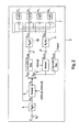
- FIG. 8 shows an exemplary embodiment of a method or rotation rate sensor with predefinition of a frequency identification signal as a harmonic setpoint value for the controlled variable, by means of sigma-delta modulation.
- the exemplary capacitor which is illustrated in FIG. 1 and is composed of a trimming electrode element 1 and a mass electrode element 2 is as a parallel-plate capacitor, wherein the distance or the distance g i over the gap is embodied in the z direction between the two electrodes, and the deflection of the mass electrode element in the primary mode occurs in the x direction, wherein the change in the overlapping area occurs in the x direction, and the deflection of the mass electrode element in the secondary mode occurs in the z direction.
- FIG. 2 illustrates an exemplary method or an exemplary rotation rate sensor comprising a control arrangement 3 in which firstly a control error variable is formed from the controlled variable y with predefinition of a control reference variable y D , wherein the controlled variable y represents the detected deflection of the seismic mass in the direction of its secondary mode, and wherein the control reference variable is a harmonic frequency identification signal with the frequency ⁇ s modulated with the frequency of the primary mode ⁇ 1 , after which the control error variable which is formed in this way is fed to a first controller unit 4 in which the resetting variable ⁇ S is generated.
- the resetting variable ⁇ S is, on the one hand, fed directly to the manipulated variable transformation unit 7 and, furthermore, the resetting variable ⁇ S is demodulated with two harmonic signals, phase-shifted through 90° with respect to one another, in a first demodulator unit 5 , as a result of which a quadrature variable ⁇ S,S and a rotation rate variable ⁇ S,C are acquired, jointly symbolized as ⁇ S , after which a quadrature control error variable is generated from the quadrature variable u S,S as a function of a quadrature reference variable, in particular with the value “0”, which quadrature control error variable is fed to a quadrature controller unit 10 which makes available the quadrature manipulated variable ⁇ c , or referred to here as ⁇ C,0 , on the output side, and wherein the rotation rate variable ⁇ S,C demodulated in a second demodulator unit 8 with the frequency ⁇ s , as a result of which a frequency variable ⁇ S,CC
- FIG. 8 illustrates the rotation rate sensor and therefore also the corresponding method using the sigma-delta modulator.
- the rotation rate sensor comprises a control arrangement 3 in which firstly a control error variable is formed from the controlled variable y with predefinition of a control reference variable, wherein the controlled variable y represents the detected deflection of the seismic mass in the direction of its secondary mode, and wherein the control reference variable is a harmonic frequency identification signal with the frequency ⁇ s modulated with the frequency of the primary mode ⁇ 1 , after which the control error variable formed in this way is fed to a first controller unit 4 whose output signal is then digitized in a quantizer 12 with the clock frequency f s and the bit sequence which is generated as a result is subsequently demodulated in a digital fashion with two harmonic signals, phase-shifted through 90° with respect to one another, in a first digital demodulator unit 5 , as a result of which a quadrature variable ⁇ S,S and a rotation rate variable ⁇ S,C are acquired, after
- the rotation rate variable ⁇ S,C is demodulated in a second demodulator unit 8 with the frequency ⁇ s , as a result of which a frequency variable ⁇ S,CC is acquired, after which a frequency control error variable is generated from the frequency variable as a function of a frequency reference variable, in particular with the value “0”, which frequency control error variable is fed to a frequency controller unit 9 which makes available the resonance frequency manipulated variable referred to here as ⁇ T, 0, on the output side.
- the rotation rate variable ⁇ S,C is also low-pass-filtered and forms the output signal ⁇ S,C0 of the sensor which contains the information about the detected rotation rate.
- the rotation rate sensor comprises a resetting unit 11 which makes available the resetting variable ⁇ SD , for example as a defined constant resetting value.
- the control arrangement comprises, for example, a sigma-delta converter with which the controlled variable is digitized and after which the resonance frequency manipulated variable, the quadrature manipulated variable and the resetting variable are generated as digital variables.
- the sigma-delta modulator embodied as an electro-mechanical sigma-delta modulator, comprises here a capacitance/voltage converter 13 which is arranged upstream of the first controller unit 4 on the input side, the first controller unit 4 itself, a quantizer 12 which is connected to the latter on the output side and having the sampling frequency f s , and a digital/analog converter (not illustrated) and a voltage/force transducer (not illustrated) for feeding back the control process.
- the first and the fourth trimming voltages U 1 , U 4 are processed by means of a first mixer M 1
- the second and the third trimming voltages U 2 , U 3 are processed by means of a second mixer M 2 , each as a function of the digital output signal of the quantizer 12 .
- micro-electro-mechanical rotation rate sensors have two weakly damped mechanical vibration modes which are orthogonal with respect to one another, the so-called primary and secondary modes, which are coupled by means of the Coriolis effect when a rotation rate occurs.
- primary and secondary modes which are coupled by means of the Coriolis effect when a rotation rate occurs.
- further coupling generally occurs between the primary and secondary modes, unbalance effect or quadrature.
- the signal components have a phase difference of 90° owing to the Coriolis and unbalance effects.
- the output signal can accordingly be decomposed into a rotation rate component and a quadrature component.
- the conventional control concept of micro-mechanical rotation rate sensors therefore typically comprises a quadrature controller which compensates the signal component owing to the unbalance effect by using an additional actuator system. Any offset drifting of the rotation rate component in the output signal owing to demodulation errors can thereby be avoided.
- In order to increase sensitivity generally extremely weakly damped mechanical structures are used.
- the resulting slow dynamic response behavior of the sensor owing to a rotation rate can be improved by compensating the rotation rate component using further suitable actuators in a resetting controller (also referred to as locking mode).
- the desired sensor dynamics are then defined by the closed circuit of the resetting controller.
- the maximum sensitivity of the rotation rate sensor is achieved if the resonance frequencies of the primary and secondary modes are identical.
- the present invention preferably deals with the design of an overall control concept which comprises the quadrature controller, resetting controller and frequency controller.
- the sensor type on which this invention is based is expediently a capacitive rotation rate sensor.
- the excitation and the reading out of the primary and secondary oscillations are carried out by means of capacitive actuators and sensors.
- the rotation rate sensor in the primary mode is made to oscillate harmonically with a constant amplitude.
- the frequency of the oscillation corresponds here to the resonance frequency of the primary mode.
- q 1 and q 2 denote the primary and secondary modes
- ⁇ denotes the rotation rate
- u 1 , . . . , u m denote the voltages at the capacitive actuators for influencing the secondary mode.
- the positive constants m 2 , d 2 and k 2 correspond to the coefficient of inertia, the damping coefficient and the rigidity coefficient
- the constants c 21 and k 21 which can assume both positive and negative values, correspond to the coupling terms owing to the Coriolis effect and unbalance effect.
- the nonlinear input term f 2 (q 1 , q 2 , u 1 , . . . , u m ) depends on the arrangement of the capacitive actuators.
- parallel-plate capacitors are assumed, as shown in FIG. 1 , they can be designed in such a way that both harmonic excitation of the secondary mode and compensation of the coupling term k 21 q 1 are possible by applying a constant voltage component.
- the constant component causes the resonance frequency of the secondary mode to be inherently influenced.
- the capacitance C i and the stored energy W p,i of the i-th actuator are then obtained as:
- u 1 ⁇ square root over ( ⁇ T ⁇ C + ⁇ S ) ⁇
- u 2 ⁇ square root over ( ⁇ T + ⁇ C ⁇ S ) ⁇
- u 3 ⁇ square root over ( ⁇ T + ⁇ C + ⁇ S ) ⁇
- u 4 ⁇ square root over ( ⁇ T ⁇ C ⁇ S ) ⁇ (5)
- Equation (6) shows that the transformed input variables are now decoupled from one another.
- the input ⁇ S can be used for harmonically exciting the secondary mode, the input ⁇ C for compensating the unbalance and the input ⁇ T for trimming the resonance frequency of the secondary mode.
- ⁇ 2 1 2 ⁇ b 2 m 2 ⁇ ⁇ 2
- ⁇ c k 21 ⁇ ⁇ c ⁇ 1 ⁇ c 21 ( 10 ) and the inputs ⁇ T,0 , ⁇ C,0 , ⁇ S,S and ⁇ S,C .
- the harmonically oscillating system variables (q 2 , ⁇ s , . . . ) are denoted as “fast” signals and the associated Fourier coefficients (Q 2,S , Q 2,C , ⁇ S,S , ⁇ S,C , . . . ) are denoted as “slow” signals.
- the rotation rate sensor For the operation of the rotation rate sensor, it is possible to differentiate between the so-called “split mode” and the “matched mode”.
- the input ⁇ T,0 is constant and the absolute value of the difference between the frequencies assumes a constant value
- a frequency interval ⁇ 1 ⁇ 2 ⁇ 0 which is as small as possible is aimed at.
- the individual components ⁇ S,C0 , ⁇ S,CC and ⁇ S,S0 can be acquired by demodulating the manipulated variable ⁇ S , as is shown in FIG. 2 .
- the Fourier coefficient ⁇ S,C0 in (13) is proportional to the rotation rate and therefore serves as an output of the rotation rate sensor.
- the actual quadrature control is then carried out by compensating the variable ⁇ S,S0 by means of the input variable ⁇ C,0 .
- the distance from the input ⁇ C,0 to the output ⁇ S,S0 which is used as the basis for the design of the quadrature controller R Q (s) is given by the steady-state relationship
- the transmission function of the closed circuit of the subordinate resetting controller is not precisely equal to 1.
- the response to the defined harmonic setpoint value then has a phase shift ⁇ 0 and change A 0 in amplitude in the steady state which can be corrected in the subsequent demodulation by demodulating with A 0 cos( ⁇ S t+ ⁇ 0 ) instead of cos( ⁇ S t).
- the exemplary reading out of a sensor by means of an electro-mechanical sigma-delta (SD) modulator in the locking mode (resetting controller) provides a large number of advantages over conventional reading systems without locked operation. As a result of the locked operation, it is possible, inter alia, to improve the bandwidth, the dynamic range and the linearity.
- the design of an electro-mechanical SD modulator is shown in FIG. 3 and is composed of a sensor, the capacitance/voltage converter (C/V), the filter or the first controller unit R R (s), which corresponds to the resetting controller described above, a quantizer with a sampling frequency f S , the digital/analog converter (DAC) and a voltage/force transducer ( ⁇ F/V).
- FIG. 4 a simplified control circuit is shown with an input F in , a transmission function H(s), which models the system comprised of the sensor and filter R R (s), the quantization noise e and an output D 0 which is fed back.
- the output signal for the closed circuit is obtained in the Laplace space as
- ⁇ D 0 F in ⁇ ⁇ 1 1 + 1 H ⁇ ( s ) ⁇ STF + e ⁇ 1 1 + H ⁇ ( s ) ⁇ NTF . ( 16 )
- Two local minimums can be determined in the spectrum; the right-hand one results from the band pass filter and the left-hand one from the transmission function of the rotation rate sensor owing to the secondary mode.
- the quality can be considerably improved if the two local minimums lie one on top of the other.
- the digital output signal is fed back to the sensor element via a DAC.
- the linearity of the sensor is improved by the active feedback. This causes the measurement signal at the input to be compensated as much as possible, so that in the ideal case the sensor has a negligible differential signal.
- the statement should be modified to the effect that the signal which is to be measured is compensated on average, and the fault only acts on the sensor as an input signal.
- the use of multi-bit solutions permits the variance between the input signal and output signal to be reduced, thereby improving the quality of the overall system with respect to linearity.
- the feedback is carried out capacitively via a pulse-width-modulated signal, a single or multi-bit voltage signal or a single or multi-bit charge signal.
- the multi-bit feedback can be obtained either by means of a specific D/A converter, which carries out implicit linearization of the feedback force, as in FIG. 6 a , or by using a plurality of feedback electrodes, as can be seen in FIG. 6 b.
- a fully differential design is also frequently selected which does not have the abovementioned disadvantages and is illustrated in FIG. 7 b .
- a dedicated amplifier can be selected for each capacitor. However, this results in a large number of amplifiers and increases the chip surface.
- the control concept presented above and the sigma-delta modulator are combined to form a further exemplary embodiment which is illustrated with respect to FIG. 8 .
- the signal ⁇ S is replaced by ⁇ SD .
- the signal ⁇ SD defines the force feedback of the sigma-delta modulator and can be set to a constant value.
- the three different manipulated variables ⁇ SD , ⁇ C,0 and ⁇ T,0 are prevented from influencing one another by means of the input variable transformation described.
- the four voltages u 1+ , u 2 ⁇ , u 3+ , and u 4 ⁇ are impressed, via the mixers M 1 and M 2 , on the corresponding electrodes of the capacitive actuators of the rotation rate sensor.
- the sigma-delta modulator is composed of a capacitance/voltage converter (C/V), a loop filter (R R (s)), a 1-bit quantizer, which is clocked with a sampling frequency f s , and a force feedback (DAC) defined by the two mixers M 1 and M 2 .
- the two mixers M 1 and M 2 are actuated with the output signal of the sigma-delta modulator.
- the force feedback acting on the sensor by means of the voltages u 1 , u 2 , u 3 and u 4 therefore occurs as a result of switching over between the current levels of the signals u 1+ and u 4 ⁇ or u 2 ⁇ and u 3+ .
- One particularly advantageous feature of the method and of the rotation rate sensor is the nonlinear input variable transformation (5) as well as the use of an electro-mechanical sigma-delta modulator with continuous timing.
- the use of the SD converter with continuous timing for reading out sensors brings a wide variety of advantages.
- the first advantage is the reduced power consumption compared to the switch/capacitor technology.
- the operational amplifiers which are used require less bandwidth up to a factor of 10, and therefore less current up to a factor of 10. This leads to drastically lower energy consumption, which plays a particular role especially in the strongly growing market of mobile sensor systems.
- SD converters with continuous timing have an implicit anti-aliasing filter, which filters frequencies above f s /2. Although the sensor already has a low-pass behavior, it does not sufficiently reduce frequencies above the Nyquist frequency, and the properties of this filter cannot be freely adjusted either.
- the properties of SD converters with continuous timing reduce the expenditure on circuitry and the costs as well as the necessary power consumption. Furthermore, the lack of cyclical recharging of the reading electrodes on the test mass results in a smaller reading force, which leads to an increase in the signal-to-noise interval and therefore to improved resolution.
- the frequency controller, quadrature controller and resetting controller can be designed independently of one another for the completely decoupled overall system with the new, transformed input variables ( ⁇ T , ⁇ C and ⁇ S ).
- the proposed control concept has the advantage that there is no longer a need for demodulation of the output signal and therefore no longer a need for decoupling of the quadrature signal and rotation rate signal provided that the “fast” resetting controller is configured to be sufficiently robust with respect to changes in parameter (in particular of the secondary resonance frequency). Decomposition into a quadrature component and rotation rate component is effected by demodulation of the manipulated variable of the resetting controller.
Abstract
Description
where i is in each case an index relating to the numbering of the electrode elements, gi is the distance over the gap between the trimming electrode element and the associated mass electrode element in the undeflected state, Ai is the overlapping area between the trimming electrode element and the associated mass electrode element in the undeflected state, the product±ri times ti times q1 is the change in the overlapping area as a function of the deflection of the primary mode q1, wherein ti is the overlapping depth between the trimming electrode element and the associated mass electrode element and ri is a first positive geometric constant relating to the deflection of the primary mode q1, and the product±si times q2 is the change in the distance over the gap between the trimming electrode element and the mass electrode element as a function of the deflection of the secondary mode q2, wherein si is a second positive geometric constant relating to the deflection of the secondary mode q2.
u 1=√{square root over (ũ T −ũ C +ũ S)}, u 2=√{square root over (ũ T +ũ C −ũ S)},
u 3=√{square root over (ũ T +ũ C +ũ S)}, u 4=√{square root over (ũ T −ũ C −ũ S)}.
u 1=√{square root over (ũ T −ũ C +ũ S)}, u 2=√{square root over (ũ T +ũ C −ũ S)},
u 3=√{square root over (ũ T +ũ C +ũ S)}, u 4=√{square root over (ũ T −ũ C −ũ S)}.
m 2 {umlaut over (q)} 2 +d 2 {dot over (q)} 2 +k 2 q 2 =f 2(q 1 ,q 2 ,u 1 , . . . ,u m)+Ωc 21 {dot over (q)} 1 −k 21 q 1 (1)
with the electrical voltage ui, the dielectric constant ∈0, the gap gi, the overlapping length li, the depth ti and the overlapping area Ai=liti in the nondistorted state. The entire impressed force of the capacitive actuators, f2 in (1), is calculated as follows
u 1=√{square root over (ũ T −ũ C +ũ S)}, u 2=√{square root over (ũ T +ũ C −ũ S)},
u 3=√{square root over (ũ T +ũ C +ũ S)}, u 4=√{square root over (ũ T −ũ C −ũ S)} (5)
m 2 {umlaut over (q)} 2 +d 2 {dot over (q)} 2+(k 2 −k 2,T ũ T)q 2 =b 2 ũ S +Ωc 21 {dot over (q)} 1−(k 21 +k 21,C ũ C)q 1 (7)
then the entire force acting on the secondary mode where
can in turn be approximated in the form (6).
with the damping parameter and the natural frequency of the secondary mode
as well as the input and unbalance parameters
and the inputs ŨT,0, ŨC,0, ŨS,S and ŨS,C. In the text which follows, the harmonically oscillating system variables (q2, ũs, . . . ) are denoted as “fast” signals and the associated Fourier coefficients (Q2,S, Q2,C, ŨS,S, ŨS,C, . . . ) are denoted as “slow” signals.
The associated cascaded control structure is illustrated in
Claims (15)
u 1=√{square root over (ũ T −ũ C +ũ S)}, u 2=√{square root over (ũ T +ũ C −ũ S)},
u 3=√{square root over (ũ T +ũ C +ũ S)}, u 4=√{square root over (ũ T −ũ C −ũ S)}.
Applications Claiming Priority (4)
| Application Number | Priority Date | Filing Date | Title |
|---|---|---|---|
| DE102010011781 | 2010-03-17 | ||
| DE102010011781.1 | 2010-03-17 | ||
| DE102010011781 | 2010-03-17 | ||
| PCT/EP2011/054090 WO2011113917A1 (en) | 2010-03-17 | 2011-03-17 | Method for the decoupled control of the quadrature and the resonance frequency of a micro-mechanical rotation rate sensor by means of sigma-delta-modulation |
Publications (2)
| Publication Number | Publication Date |
|---|---|
| US20130197858A1 US20130197858A1 (en) | 2013-08-01 |
| US9535084B2 true US9535084B2 (en) | 2017-01-03 |
Family
ID=44080141
Family Applications (1)
| Application Number | Title | Priority Date | Filing Date |
|---|---|---|---|
| US13/634,585 Active 2034-04-27 US9535084B2 (en) | 2010-03-17 | 2011-03-17 | Method for the decoupled control of the quadrature and the resonance frequency of a micro-mechanical rotation rate sensor by means of sigma-delta-modulation |
Country Status (6)
| Country | Link |
|---|---|
| US (1) | US9535084B2 (en) |
| EP (1) | EP2547985B1 (en) |
| KR (1) | KR101803990B1 (en) |
| CN (1) | CN102893127B (en) |
| DE (1) | DE102011005745A1 (en) |
| WO (1) | WO2011113917A1 (en) |
Cited By (2)
| Publication number | Priority date | Publication date | Assignee | Title |
|---|---|---|---|---|
| US10677611B2 (en) * | 2015-10-08 | 2020-06-09 | Albert-Ludwigs-Universitat Freiburg | Circular system and method for the digital correction of modulation effects in eletromechanical delta-sigma modulators |
| US20220057207A1 (en) * | 2020-08-19 | 2022-02-24 | Invensense, Inc. | Minimizing a delay of a capacitance-to-voltage converter of a gyroscope by including such converter within a bandpass sigma-delta analog-to-digital converter of the gyroscope |
Families Citing this family (15)
| Publication number | Priority date | Publication date | Assignee | Title |
|---|---|---|---|---|
| US9535084B2 (en) | 2010-03-17 | 2017-01-03 | Continental Teves Ag & Co. Ohg | Method for the decoupled control of the quadrature and the resonance frequency of a micro-mechanical rotation rate sensor by means of sigma-delta-modulation |
| KR101889991B1 (en) * | 2010-03-17 | 2018-08-20 | 콘티넨탈 테베스 아게 운트 코. 오하게 | Method for the decoupled control of the quadrature and the resonance frequency of a micro-mechanical gyroscope |
| DE102010053022B4 (en) * | 2010-12-02 | 2014-01-09 | Hahn-Schickard-Gesellschaft für angewandte Forschung e.V. | Device for measuring a rate of rotation |
| DE102012224081A1 (en) * | 2012-12-20 | 2014-06-26 | Continental Teves Ag & Co. Ohg | Sensor for detecting a rate of rotation of an object |
| US9506757B2 (en) * | 2013-03-14 | 2016-11-29 | Invensense, Inc. | Duty-cycled gyroscope |
| DE102013218973B4 (en) | 2013-09-20 | 2015-11-19 | Albert-Ludwigs-Universität Freiburg | Method and circuit for time-continuous detection of the position of the sensor mass with simultaneous feedback for capacitive sensors |
| FR3011701B1 (en) * | 2013-10-04 | 2017-07-28 | Commissariat Energie Atomique | CONTINUOUS TIME QUANTIFICATION DEVICE, RADIO FREQUENCY SIGNAL RECEIVER COMPRISING SUCH DEVICE, AND CONTINUOUS TIME QUANTIFICATION METHOD |
| GB2547415A (en) * | 2016-02-09 | 2017-08-23 | Atlantic Inertial Systems Ltd | Inertial sensors |
| CN105890856B (en) * | 2016-04-05 | 2018-07-10 | 中国科学院力学研究所 | A kind of gap decoupled identification method of double gap mechanical mechanism |
| US10247600B2 (en) | 2016-11-10 | 2019-04-02 | Analog Devices, Inc. | Mode-matching of MEMS resonators |
| CN106840145B (en) * | 2016-12-19 | 2020-03-27 | 北京时代民芯科技有限公司 | Control system of micro-mechanical rate integrating ring gyroscope |
| US10852136B2 (en) | 2017-08-30 | 2020-12-01 | Analog Devices, Inc. | Frequency mismatch detection method for mode matching in gyroscopes |
| DE102018219333B3 (en) * | 2018-11-13 | 2020-03-26 | Albert-Ludwigs-Universität Freiburg | METHOD FOR AUTOMATIC FREQUENCY ADJUSTMENT OF A FILTER IN A CLOSED CONTROL LOOP |
| EP3786581B1 (en) * | 2019-08-29 | 2023-06-07 | Murata Manufacturing Co., Ltd. | Offset-cancelling capacitive mems gyroscope |
| JP2021067624A (en) * | 2019-10-28 | 2021-04-30 | セイコーエプソン株式会社 | Inertial measurement device, electronic apparatus, and mobile entity |
Citations (22)
| Publication number | Priority date | Publication date | Assignee | Title |
|---|---|---|---|---|
| US5481914A (en) * | 1994-03-28 | 1996-01-09 | The Charles Stark Draper Laboratory, Inc. | Electronics for coriolis force and other sensors |
| US5847279A (en) | 1995-06-29 | 1998-12-08 | Asulab S.A. | Angular speed measuring device |
| US6067858A (en) | 1996-05-31 | 2000-05-30 | The Regents Of The University Of California | Micromachined vibratory rate gyroscope |
| US6089089A (en) | 1997-10-14 | 2000-07-18 | Microsensors, Inc. | Multi-element micro gyro |
| US6250156B1 (en) | 1996-05-31 | 2001-06-26 | The Regents Of The University Of California | Dual-mass micromachined vibratory rate gyroscope |
| US20010039834A1 (en) | 2000-03-17 | 2001-11-15 | Hsu Ying W. | Method of canceling quadrature error in an angular rate sensor |
| WO2003010492A1 (en) | 2001-07-25 | 2003-02-06 | Northrop Grumman Corporation | Phase insensitive quadrature nulling method and apparatus for coriolis angular rate sensors |
| US20030061877A1 (en) | 2001-10-03 | 2003-04-03 | Stewart Robert E. | Micromachined silicon tuned counterbalanced accelerometer-gyro with quadrature nulling |
| DE10248733A1 (en) | 2002-10-18 | 2004-05-06 | Litef Gmbh | Method for electronically tuning the read oscillation frequency of a Coriolis gyro |
| US20040173023A1 (en) * | 2003-03-06 | 2004-09-09 | Hai Yan | Micromachined vibratory gyroscope with electrostatic coupling |
| DE10320675A1 (en) | 2003-05-08 | 2004-12-02 | Litef Gmbh | Operating method for a Coriolis gyro and appropriate evaluation / control electronics |
| US20050082252A1 (en) * | 2003-10-20 | 2005-04-21 | Nasiri Steven S. | Method of making an X-Y axis dual-mass tuning fork gyroscope with vertically integrated electronics and wafer-scale hermetic packaging |
| WO2005066585A1 (en) | 2003-12-23 | 2005-07-21 | Litef Gmbh | Method for compensating a coriolis gyroscope quadrature bias and a coriolis gyroscope for carrying out said method |
| US20050268716A1 (en) * | 2004-06-08 | 2005-12-08 | Honeywell International Inc. | Built in test for mems vibratory type inertial sensors |
| US20060020409A1 (en) | 2002-10-18 | 2006-01-26 | Werner Schroeder | Method for electronically adjusting the selective oscillation frequency of a coriolis gyro |
| US20060101910A1 (en) | 2002-10-18 | 2006-05-18 | Werner Schroeder | Method for electronic tuning of the read oscillation frequency of a coriolis gyro |
| WO2008031480A1 (en) | 2006-09-15 | 2008-03-20 | Northrop Grumman Litef Gmbh | Microelectromechanical sensor and operating method for a microelectromechanical sensor |
| US20080284628A1 (en) * | 2005-01-26 | 2008-11-20 | Rainer Willig | Delta Sigma Modulator |
| US20100294039A1 (en) * | 2009-05-21 | 2010-11-25 | Analog Devices, Inc. | Mode-Matching Apparatus and Method for Micromachined Inertial Sensors |
| CN102893128A (en) | 2010-03-17 | 2013-01-23 | 大陆-特韦斯贸易合伙股份公司及两合公司 | Method for the decoupled control of the quadrature and the resonance frequency of a micro-mechanical gyroscope |
| US20130197858A1 (en) | 2010-03-17 | 2013-08-01 | Albert-Ludwigs-University Of Freiburg | Method for the decoupled control of the quadrature and the resonance frequency of a micro-mechanical rotation rate sensor by means of sigma-delta-modulation |
| US8661898B2 (en) | 2008-10-14 | 2014-03-04 | Watson Industries, Inc. | Vibrating structural gyroscope with quadrature control |
Family Cites Families (1)
| Publication number | Priority date | Publication date | Assignee | Title |
|---|---|---|---|---|
| CN101519359B (en) * | 2009-04-16 | 2012-07-25 | 李汉毅 | Method for recovering polyimide through hydrolysis |
-
2011
- 2011-03-17 US US13/634,585 patent/US9535084B2/en active Active
- 2011-03-17 CN CN201180024166.1A patent/CN102893127B/en active Active
- 2011-03-17 KR KR1020127027137A patent/KR101803990B1/en active IP Right Grant
- 2011-03-17 EP EP11710454.7A patent/EP2547985B1/en active Active
- 2011-03-17 DE DE102011005745A patent/DE102011005745A1/en not_active Withdrawn
- 2011-03-17 WO PCT/EP2011/054090 patent/WO2011113917A1/en active Application Filing
Patent Citations (34)
| Publication number | Priority date | Publication date | Assignee | Title |
|---|---|---|---|---|
| US5481914A (en) * | 1994-03-28 | 1996-01-09 | The Charles Stark Draper Laboratory, Inc. | Electronics for coriolis force and other sensors |
| US5847279A (en) | 1995-06-29 | 1998-12-08 | Asulab S.A. | Angular speed measuring device |
| US6067858A (en) | 1996-05-31 | 2000-05-30 | The Regents Of The University Of California | Micromachined vibratory rate gyroscope |
| US6250156B1 (en) | 1996-05-31 | 2001-06-26 | The Regents Of The University Of California | Dual-mass micromachined vibratory rate gyroscope |
| US6089089A (en) | 1997-10-14 | 2000-07-18 | Microsensors, Inc. | Multi-element micro gyro |
| US20010039834A1 (en) | 2000-03-17 | 2001-11-15 | Hsu Ying W. | Method of canceling quadrature error in an angular rate sensor |
| WO2003010492A1 (en) | 2001-07-25 | 2003-02-06 | Northrop Grumman Corporation | Phase insensitive quadrature nulling method and apparatus for coriolis angular rate sensors |
| US20030159510A1 (en) | 2001-07-25 | 2003-08-28 | Stewart Robert E. | Phase insensitive quadrature nulling method and apparatus for coriolis angular rate sensors |
| US20030061877A1 (en) | 2001-10-03 | 2003-04-03 | Stewart Robert E. | Micromachined silicon tuned counterbalanced accelerometer-gyro with quadrature nulling |
| US20060020409A1 (en) | 2002-10-18 | 2006-01-26 | Werner Schroeder | Method for electronically adjusting the selective oscillation frequency of a coriolis gyro |
| US20060101910A1 (en) | 2002-10-18 | 2006-05-18 | Werner Schroeder | Method for electronic tuning of the read oscillation frequency of a coriolis gyro |
| US7337665B2 (en) | 2002-10-18 | 2008-03-04 | Litef Gmbh | Method for electronically tuning the readout vibration of a coriolis gyroscope |
| WO2004038331A1 (en) | 2002-10-18 | 2004-05-06 | Litef Gmbh | Method for electronically tuning the readout vibration frequency of a coriolis gyroscope |
| US20060010999A1 (en) | 2002-10-18 | 2006-01-19 | Werner Schroeder | Method for electronically tuning the readout vibration of a coriolis gyroscope |
| DE10248733A1 (en) | 2002-10-18 | 2004-05-06 | Litef Gmbh | Method for electronically tuning the read oscillation frequency of a Coriolis gyro |
| US20040173023A1 (en) * | 2003-03-06 | 2004-09-09 | Hai Yan | Micromachined vibratory gyroscope with electrostatic coupling |
| DE10320675A1 (en) | 2003-05-08 | 2004-12-02 | Litef Gmbh | Operating method for a Coriolis gyro and appropriate evaluation / control electronics |
| US7805993B2 (en) | 2003-05-08 | 2010-10-05 | Litef Gmbh | Operating method for a Coriolis gyro, and evaluation/control electronics which are suitable for this purpose |
| US20050082252A1 (en) * | 2003-10-20 | 2005-04-21 | Nasiri Steven S. | Method of making an X-Y axis dual-mass tuning fork gyroscope with vertically integrated electronics and wafer-scale hermetic packaging |
| DE10360962A1 (en) | 2003-12-23 | 2005-07-28 | Litef Gmbh | Method for quadrature bias compensation in a Coriolis gyro and suitable Coriolis gyro |
| WO2005066585A1 (en) | 2003-12-23 | 2005-07-21 | Litef Gmbh | Method for compensating a coriolis gyroscope quadrature bias and a coriolis gyroscope for carrying out said method |
| US7481110B2 (en) | 2003-12-23 | 2009-01-27 | Litef Gmbh | Method for quadrature-bias compensation in a Coriolis gyro, as well as a Coriolis gyro which is suitable for this purpose |
| CN1898528A (en) | 2003-12-23 | 2007-01-17 | 利特夫有限责任公司 | Method for compensating a coriolis gyroscope quadrature bias and a coriolis gyroscope for carrying out said method |
| US20070144255A1 (en) | 2003-12-23 | 2007-06-28 | Eberhard Handrich | Method for quadrature-bias compensation in a coriolis gyro, as well as a coriolis gyro which is suitable for this purpose |
| US20050268716A1 (en) * | 2004-06-08 | 2005-12-08 | Honeywell International Inc. | Built in test for mems vibratory type inertial sensors |
| US20080284628A1 (en) * | 2005-01-26 | 2008-11-20 | Rainer Willig | Delta Sigma Modulator |
| US20100186503A1 (en) | 2006-09-15 | 2010-07-29 | Guenter Spahlinger | Microelectromechanical sensor and operating method for a microelectromechanical sensor |
| WO2008031480A1 (en) | 2006-09-15 | 2008-03-20 | Northrop Grumman Litef Gmbh | Microelectromechanical sensor and operating method for a microelectromechanical sensor |
| US8661898B2 (en) | 2008-10-14 | 2014-03-04 | Watson Industries, Inc. | Vibrating structural gyroscope with quadrature control |
| US20100294039A1 (en) * | 2009-05-21 | 2010-11-25 | Analog Devices, Inc. | Mode-Matching Apparatus and Method for Micromachined Inertial Sensors |
| CN102893128A (en) | 2010-03-17 | 2013-01-23 | 大陆-特韦斯贸易合伙股份公司及两合公司 | Method for the decoupled control of the quadrature and the resonance frequency of a micro-mechanical gyroscope |
| EP2547984A1 (en) | 2010-03-17 | 2013-01-23 | Continental Teves AG & Co. oHG | Method for the decoupled control of the quadrature and the resonance frequency of a micro-mechanical gyroscope |
| US20130197858A1 (en) | 2010-03-17 | 2013-08-01 | Albert-Ludwigs-University Of Freiburg | Method for the decoupled control of the quadrature and the resonance frequency of a micro-mechanical rotation rate sensor by means of sigma-delta-modulation |
| US20130199263A1 (en) | 2010-03-17 | 2013-08-08 | Continental Teves Ag & Co. Ohg | Method for the decoupled control of the quadrature and the resonance frequency of a micro-mechanical gyroscope |
Non-Patent Citations (7)
| Title |
|---|
| Entire patent prosecution history of U.S. Appl. No. 13/634,301, filed Nov. 13, 2012, entitled, "Method for the Decoupled Control of the Quadrature and the Resonance Frequency of a Micro-Mechanical Gyroscope." |
| Final Office Action mailed Dec. 14, 2015 in U.S. Appl. No. 13/634,301. |
| German Search Report corresponding to German Application No. 10 2011 005 744.7 dated Apr. 12, 2012. |
| German Search Report for Application No. DE 10 2011 005 745.5 dated Apr. 13, 2012. |
| International Search Report corresponding to International Application No. PCT/EP2011/054089, dated Jun. 28, 2011. |
| International Search Report for PCT International Application No. PCT/EP2011/054090 mailed Jun. 28, 2011. |
| Office Action mailed Aug. 12, 2015 in U.S. Appl. No. 13/634,301. |
Cited By (4)
| Publication number | Priority date | Publication date | Assignee | Title |
|---|---|---|---|---|
| US10677611B2 (en) * | 2015-10-08 | 2020-06-09 | Albert-Ludwigs-Universitat Freiburg | Circular system and method for the digital correction of modulation effects in eletromechanical delta-sigma modulators |
| US11268828B2 (en) | 2015-10-08 | 2022-03-08 | Albert-Ludwigs-Universitat Freiburg | Circuit arrangement and method for the digital correction of modulation effects in electromechanical delta-sigma modulators |
| US20220057207A1 (en) * | 2020-08-19 | 2022-02-24 | Invensense, Inc. | Minimizing a delay of a capacitance-to-voltage converter of a gyroscope by including such converter within a bandpass sigma-delta analog-to-digital converter of the gyroscope |
| US11821731B2 (en) * | 2020-08-19 | 2023-11-21 | Invensense, Inc. | Minimizing a delay of a capacitance-to-voltage converter of a gyroscope by including such converter within a bandpass sigma-delta analog-to-digital converter of the gyroscope |
Also Published As
| Publication number | Publication date |
|---|---|
| CN102893127A (en) | 2013-01-23 |
| DE102011005745A1 (en) | 2011-09-22 |
| EP2547985B1 (en) | 2016-03-16 |
| KR20130020776A (en) | 2013-02-28 |
| WO2011113917A1 (en) | 2011-09-22 |
| US20130197858A1 (en) | 2013-08-01 |
| KR101803990B1 (en) | 2017-12-01 |
| CN102893127B (en) | 2016-02-17 |
| EP2547985A1 (en) | 2013-01-23 |
Similar Documents
| Publication | Publication Date | Title |
|---|---|---|
| US9535084B2 (en) | Method for the decoupled control of the quadrature and the resonance frequency of a micro-mechanical rotation rate sensor by means of sigma-delta-modulation | |
| US9377483B2 (en) | Method for the decoupled control of the quadrature and the resonance frequency of a micro-mechanical gyroscope | |
| CN110865580B (en) | Hemispherical resonant gyroscope fully-differential control system and control method based on time division multiplexing | |
| Saukoski et al. | Zero-rate output and quadrature compensation in vibratory MEMS gyroscopes | |
| US6718823B2 (en) | Pulse width modulation drive signal for a MEMS gyroscope | |
| US8042393B2 (en) | Arrangement for measuring a rate of rotation using a vibration sensor | |
| US7444869B2 (en) | Force rebalancing and parametric amplification of MEMS inertial sensors | |
| US10677611B2 (en) | Circular system and method for the digital correction of modulation effects in eletromechanical delta-sigma modulators | |
| KR100592985B1 (en) | Vibration type angular velocity sensor | |
| US8763441B2 (en) | Method and apparatus for self-calibration of gyroscopes | |
| US5530342A (en) | Micromachined rate sensor comb drive device and method | |
| US8528403B2 (en) | Vibration compensation for yaw-rate sensors | |
| CN106052667B (en) | Resonator and the system of Coriolis axis control, device, method in vibratory gyroscope | |
| JP5725687B2 (en) | Micromechanical rotational speed sensor | |
| US6934660B2 (en) | Multi stage control architecture for error suppression in micromachined gyroscopes | |
| Marra et al. | Solving FSR versus offset-drift trade-offs with three-axis time-switched FM MEMS accelerometer | |
| US8424382B2 (en) | Microelectromechanical sensor and operating method for a microelectromechanical sensor | |
| JP2000009475A (en) | Angular velocity detection device | |
| Marra et al. | Single-resonator, time-switched FM MEMS accelerometer with theoretical offset drift complete cancellation | |
| Jia et al. | In-run scale factor compensation for MEMS gyroscope without calibration and fitting | |
| WO2011144899A1 (en) | Angular rate sensor with improved ageing properties | |
| Marra et al. | Single resonator, time-switched, low offset drift z-axis FM MEMS accelerometer | |
| Zega et al. | Towards 3-axis FM mems gyroscopes: Mechanical design and experimental validation | |
| Severov et al. | Structure and characteristics of a MEMS wave angular rate sensor with a ring resonator | |
| Jia et al. | In-run Self-calibration of Scale Factor Temperature Drifts for MEMS Gyroscope |
Legal Events
| Date | Code | Title | Description |
|---|---|---|---|
| AS | Assignment |
Owner name: CONTINENTAL TEVES AG & CO. OHG, GERMANY Free format text: ASSIGNMENT OF ASSIGNORS INTEREST;ASSIGNORS:EGRETZBERGER, MARKUS;KUGI, ANDREAS;MAIR, FLORIAN;SIGNING DATES FROM 20121024 TO 20121224;REEL/FRAME:030194/0825 Owner name: ALBERT-LUDWIGS-UNIVERSITY OF FREIBURG, GERMANY Free format text: ASSIGNMENT OF ASSIGNORS INTEREST;ASSIGNORS:NORTHEMANN, THOMAS;MAURER, MICHAEL;MANOLI, YIANNOS;SIGNING DATES FROM 20120823 TO 20120829;REEL/FRAME:030194/0590 Owner name: CONTINENTAL TEVES AG & CO. OHG, GERMANY Free format text: ASSIGNMENT OF ASSIGNORS INTEREST;ASSIGNORS:NORTHEMANN, THOMAS;MAURER, MICHAEL;MANOLI, YIANNOS;SIGNING DATES FROM 20120823 TO 20120829;REEL/FRAME:030194/0590 |
|
| FEPP | Fee payment procedure |
Free format text: PAYOR NUMBER ASSIGNED (ORIGINAL EVENT CODE: ASPN); ENTITY STATUS OF PATENT OWNER: LARGE ENTITY |
|
| STCF | Information on status: patent grant |
Free format text: PATENTED CASE |
|
| MAFP | Maintenance fee payment |
Free format text: PAYMENT OF MAINTENANCE FEE, 4TH YEAR, LARGE ENTITY (ORIGINAL EVENT CODE: M1551); ENTITY STATUS OF PATENT OWNER: LARGE ENTITY Year of fee payment: 4 |