US9544439B2 - Caller-callee association of a plurality of networked devices - Google Patents
Caller-callee association of a plurality of networked devices Download PDFInfo
- Publication number
- US9544439B2 US9544439B2 US15/046,398 US201615046398A US9544439B2 US 9544439 B2 US9544439 B2 US 9544439B2 US 201615046398 A US201615046398 A US 201615046398A US 9544439 B2 US9544439 B2 US 9544439B2
- Authority
- US
- United States
- Prior art keywords
- contact
- server
- communication
- contacts
- information
- Prior art date
- Legal status (The legal status is an assumption and is not a legal conclusion. Google has not performed a legal analysis and makes no representation as to the accuracy of the status listed.)
- Active
Links
- 238000004891 communication Methods 0.000 claims abstract description 252
- 238000000034 method Methods 0.000 claims abstract description 94
- 230000004044 response Effects 0.000 claims description 22
- 230000005540 biological transmission Effects 0.000 claims description 5
- 238000013507 mapping Methods 0.000 claims description 4
- 230000001413 cellular effect Effects 0.000 abstract description 11
- 230000008569 process Effects 0.000 description 21
- 108091006146 Channels Proteins 0.000 description 16
- 230000000875 corresponding effect Effects 0.000 description 10
- 238000013500 data storage Methods 0.000 description 8
- 238000010295 mobile communication Methods 0.000 description 7
- 230000006870 function Effects 0.000 description 6
- 230000011664 signaling Effects 0.000 description 5
- 230000009471 action Effects 0.000 description 4
- 230000005236 sound signal Effects 0.000 description 4
- 238000012546 transfer Methods 0.000 description 4
- 230000008878 coupling Effects 0.000 description 3
- 238000010168 coupling process Methods 0.000 description 3
- 238000005859 coupling reaction Methods 0.000 description 3
- 238000012545 processing Methods 0.000 description 3
- 230000008901 benefit Effects 0.000 description 2
- 230000010267 cellular communication Effects 0.000 description 2
- 230000002596 correlated effect Effects 0.000 description 2
- 230000001934 delay Effects 0.000 description 2
- 230000001419 dependent effect Effects 0.000 description 2
- 238000010586 diagram Methods 0.000 description 2
- 230000002452 interceptive effect Effects 0.000 description 2
- 230000007246 mechanism Effects 0.000 description 2
- 230000003287 optical effect Effects 0.000 description 2
- 230000008447 perception Effects 0.000 description 2
- 230000000737 periodic effect Effects 0.000 description 2
- 230000008859 change Effects 0.000 description 1
- 238000006243 chemical reaction Methods 0.000 description 1
- 238000010276 construction Methods 0.000 description 1
- 230000009977 dual effect Effects 0.000 description 1
- 230000000694 effects Effects 0.000 description 1
- 230000007717 exclusion Effects 0.000 description 1
- 239000000284 extract Substances 0.000 description 1
- 230000008676 import Effects 0.000 description 1
- 238000012423 maintenance Methods 0.000 description 1
- 238000007726 management method Methods 0.000 description 1
- 238000012544 monitoring process Methods 0.000 description 1
- 230000006855 networking Effects 0.000 description 1
- 230000008520 organization Effects 0.000 description 1
- 238000004806 packaging method and process Methods 0.000 description 1
- 238000012552 review Methods 0.000 description 1
- 230000000007 visual effect Effects 0.000 description 1
Images


Classifications
-
- H—ELECTRICITY
- H04—ELECTRIC COMMUNICATION TECHNIQUE
- H04M—TELEPHONIC COMMUNICATION
- H04M7/00—Arrangements for interconnection between switching centres
- H04M7/006—Networks other than PSTN/ISDN providing telephone service, e.g. Voice over Internet Protocol (VoIP), including next generation networks with a packet-switched transport layer
- H04M7/0066—Details of access arrangements to the networks
- H04M7/0069—Details of access arrangements to the networks comprising a residential gateway, e.g. those which provide an adapter for POTS or ISDN terminals
-
- H04L29/06027—
-
- H04L29/12122—
-
- H04L29/1216—
-
- H04L29/12584—
-
- H04L29/12896—
-
- H—ELECTRICITY
- H04—ELECTRIC COMMUNICATION TECHNIQUE
- H04L—TRANSMISSION OF DIGITAL INFORMATION, e.g. TELEGRAPHIC COMMUNICATION
- H04L47/00—Traffic control in data switching networks
- H04L47/10—Flow control; Congestion control
-
- H04L61/1547—
-
- H04L61/157—
-
- H—ELECTRICITY
- H04—ELECTRIC COMMUNICATION TECHNIQUE
- H04L—TRANSMISSION OF DIGITAL INFORMATION, e.g. TELEGRAPHIC COMMUNICATION
- H04L61/00—Network arrangements, protocols or services for addressing or naming
- H04L61/09—Mapping addresses
- H04L61/25—Mapping addresses of the same type
- H04L61/2596—Translation of addresses of the same type other than IP, e.g. translation from MAC to MAC addresses
-
- H—ELECTRICITY
- H04—ELECTRIC COMMUNICATION TECHNIQUE
- H04L—TRANSMISSION OF DIGITAL INFORMATION, e.g. TELEGRAPHIC COMMUNICATION
- H04L61/00—Network arrangements, protocols or services for addressing or naming
- H04L61/45—Network directories; Name-to-address mapping
- H04L61/4547—Network directories; Name-to-address mapping for personal communications, i.e. using a personal identifier
-
- H—ELECTRICITY
- H04—ELECTRIC COMMUNICATION TECHNIQUE
- H04L—TRANSMISSION OF DIGITAL INFORMATION, e.g. TELEGRAPHIC COMMUNICATION
- H04L61/00—Network arrangements, protocols or services for addressing or naming
- H04L61/45—Network directories; Name-to-address mapping
- H04L61/4557—Directories for hybrid networks, e.g. including telephone numbers
-
- H04L61/605—
-
- H—ELECTRICITY
- H04—ELECTRIC COMMUNICATION TECHNIQUE
- H04L—TRANSMISSION OF DIGITAL INFORMATION, e.g. TELEGRAPHIC COMMUNICATION
- H04L63/00—Network architectures or network communication protocols for network security
- H04L63/08—Network architectures or network communication protocols for network security for authentication of entities
-
- H04L65/1003—
-
- H04L65/1006—
-
- H—ELECTRICITY
- H04—ELECTRIC COMMUNICATION TECHNIQUE
- H04L—TRANSMISSION OF DIGITAL INFORMATION, e.g. TELEGRAPHIC COMMUNICATION
- H04L65/00—Network arrangements, protocols or services for supporting real-time applications in data packet communication
- H04L65/10—Architectures or entities
- H04L65/102—Gateways
- H04L65/1023—Media gateways
- H04L65/1026—Media gateways at the edge
-
- H—ELECTRICITY
- H04—ELECTRIC COMMUNICATION TECHNIQUE
- H04L—TRANSMISSION OF DIGITAL INFORMATION, e.g. TELEGRAPHIC COMMUNICATION
- H04L65/00—Network arrangements, protocols or services for supporting real-time applications in data packet communication
- H04L65/10—Architectures or entities
- H04L65/102—Gateways
- H04L65/1023—Media gateways
- H04L65/103—Media gateways in the network
-
- H—ELECTRICITY
- H04—ELECTRIC COMMUNICATION TECHNIQUE
- H04L—TRANSMISSION OF DIGITAL INFORMATION, e.g. TELEGRAPHIC COMMUNICATION
- H04L65/00—Network arrangements, protocols or services for supporting real-time applications in data packet communication
- H04L65/10—Architectures or entities
- H04L65/102—Gateways
- H04L65/1033—Signalling gateways
- H04L65/1036—Signalling gateways at the edge
-
- H—ELECTRICITY
- H04—ELECTRIC COMMUNICATION TECHNIQUE
- H04L—TRANSMISSION OF DIGITAL INFORMATION, e.g. TELEGRAPHIC COMMUNICATION
- H04L65/00—Network arrangements, protocols or services for supporting real-time applications in data packet communication
- H04L65/10—Architectures or entities
- H04L65/102—Gateways
- H04L65/1033—Signalling gateways
- H04L65/104—Signalling gateways in the network
-
- H—ELECTRICITY
- H04—ELECTRIC COMMUNICATION TECHNIQUE
- H04L—TRANSMISSION OF DIGITAL INFORMATION, e.g. TELEGRAPHIC COMMUNICATION
- H04L65/00—Network arrangements, protocols or services for supporting real-time applications in data packet communication
- H04L65/1066—Session management
- H04L65/1069—Session establishment or de-establishment
-
- H—ELECTRICITY
- H04—ELECTRIC COMMUNICATION TECHNIQUE
- H04L—TRANSMISSION OF DIGITAL INFORMATION, e.g. TELEGRAPHIC COMMUNICATION
- H04L65/00—Network arrangements, protocols or services for supporting real-time applications in data packet communication
- H04L65/1066—Session management
- H04L65/1101—Session protocols
- H04L65/1104—Session initiation protocol [SIP]
-
- H—ELECTRICITY
- H04—ELECTRIC COMMUNICATION TECHNIQUE
- H04L—TRANSMISSION OF DIGITAL INFORMATION, e.g. TELEGRAPHIC COMMUNICATION
- H04L67/00—Network arrangements or protocols for supporting network services or applications
- H04L67/01—Protocols
- H04L67/12—Protocols specially adapted for proprietary or special-purpose networking environments, e.g. medical networks, sensor networks, networks in vehicles or remote metering networks
- H04L67/125—Protocols specially adapted for proprietary or special-purpose networking environments, e.g. medical networks, sensor networks, networks in vehicles or remote metering networks involving control of end-device applications over a network
-
- H04L67/24—
-
- H—ELECTRICITY
- H04—ELECTRIC COMMUNICATION TECHNIQUE
- H04L—TRANSMISSION OF DIGITAL INFORMATION, e.g. TELEGRAPHIC COMMUNICATION
- H04L67/00—Network arrangements or protocols for supporting network services or applications
- H04L67/50—Network services
- H04L67/54—Presence management, e.g. monitoring or registration for receipt of user log-on information, or the connection status of the users
-
- H—ELECTRICITY
- H04—ELECTRIC COMMUNICATION TECHNIQUE
- H04M—TELEPHONIC COMMUNICATION
- H04M3/00—Automatic or semi-automatic exchanges
- H04M3/02—Calling substations, e.g. by ringing
-
- H—ELECTRICITY
- H04—ELECTRIC COMMUNICATION TECHNIQUE
- H04M—TELEPHONIC COMMUNICATION
- H04M7/00—Arrangements for interconnection between switching centres
- H04M7/006—Networks other than PSTN/ISDN providing telephone service, e.g. Voice over Internet Protocol (VoIP), including next generation networks with a packet-switched transport layer
- H04M7/0075—Details of addressing, directories or routing tables
-
- H—ELECTRICITY
- H04—ELECTRIC COMMUNICATION TECHNIQUE
- H04L—TRANSMISSION OF DIGITAL INFORMATION, e.g. TELEGRAPHIC COMMUNICATION
- H04L2101/00—Indexing scheme associated with group H04L61/00
- H04L2101/60—Types of network addresses
- H04L2101/618—Details of network addresses
- H04L2101/65—Telephone numbers
-
- H—ELECTRICITY
- H04—ELECTRIC COMMUNICATION TECHNIQUE
- H04L—TRANSMISSION OF DIGITAL INFORMATION, e.g. TELEGRAPHIC COMMUNICATION
- H04L41/00—Arrangements for maintenance, administration or management of data switching networks, e.g. of packet switching networks
- H04L41/12—Discovery or management of network topologies
-
- H—ELECTRICITY
- H04—ELECTRIC COMMUNICATION TECHNIQUE
- H04L—TRANSMISSION OF DIGITAL INFORMATION, e.g. TELEGRAPHIC COMMUNICATION
- H04L41/00—Arrangements for maintenance, administration or management of data switching networks, e.g. of packet switching networks
- H04L41/34—Signalling channels for network management communication
- H04L41/344—Out-of-band transfers
-
- H—ELECTRICITY
- H04—ELECTRIC COMMUNICATION TECHNIQUE
- H04L—TRANSMISSION OF DIGITAL INFORMATION, e.g. TELEGRAPHIC COMMUNICATION
- H04L67/00—Network arrangements or protocols for supporting network services or applications
- H04L67/14—Session management
-
- H—ELECTRICITY
- H04—ELECTRIC COMMUNICATION TECHNIQUE
- H04W—WIRELESS COMMUNICATION NETWORKS
- H04W84/00—Network topologies
- H04W84/02—Hierarchically pre-organised networks, e.g. paging networks, cellular networks, WLAN [Wireless Local Area Network] or WLL [Wireless Local Loop]
- H04W84/10—Small scale networks; Flat hierarchical networks
- H04W84/12—WLAN [Wireless Local Area Networks]
Definitions
- Systems for communicating voice information have been in use for some time, and typically include telephone communication systems. Communication systems and methods for using traditional telephones, including analog and digital systems have evolved to use various communication networks. These networks and supporting systems include “plain old telephone service” (POTS), public switched telephone networks (PSTN), cellular networks for mobile phones, and others. More recently, the Internet has also been used to carry real-time or near real-time voice communication signals from one point to another. Routing, switching, bridging, and other methods of packaging and delivering data from voice communications is in use but continues to evolve. More effective, less costly, and better quality communication systems and methods for using the same are needed, which this disclosure provides.
- POTS plain old telephone service
- PSTN public switched telephone networks
- cellular networks for mobile phones
- the Internet has also been used to carry real-time or near real-time voice communication signals from one point to another. Routing, switching, bridging, and other methods of packaging and delivering data from voice communications is in use but continues to evolve. More effective, less costly, and better quality communication systems and methods for using
- the present disclosure generally relates to systems and methods for establishing and maintaining communication between two or more communication devices coupled to communication networks. Some specific aspects relate to communication between a plurality of communication devices each of which is coupled to a respective network. Other aspects relate to establishing such communication by way of contact lists maintained and facilitated on systems coupled to the networks.
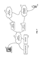
- FIG. 1 illustrates a network having multiple paths for communication of information through and over the network.
- more than one network can be coupled through ways known to those skilled in the art such as routing, bridging and the like.
- the end effect is to create a system of interconnected components which can exchange data to communicate information there between.
- the data is commonly digital in nature in modern communication systems, but the present discussion is not so limited.
- electronic signals, pulses, optical, acoustical, and other electromagnetic means for modulating communication signals can be used to communicate information across one or more legs of a network or networks.
- the signals may travel across the network or networks substantially in real time, with only the propagation delays associated therewith.
- the signals may alternately be interrupted by intervening components on the network or networks, buffered, stored, routed, bridged, etc., which introduces other latencies and delays into the propagation.
- IP Internet Protocol
- FIG. 1 specifically shows several interconnected networks and devices that provide telephonic (e.g., voice) communication between two or more communication devices coupled to the collection of networks and devices.
- the interconnected networks and devices include a Public Switched Telephone Network (PSTN) 11 , a Voice over Internet Protocol (VoIP) network 31 and a wireless network 51 .
- PSTN Public Switched Telephone Network
- VoIP Voice over Internet Protocol
- PSTN 11 is a collection of interconnected public telephone networks, designed primarily for voice communications. It also comprises a collection of Private Branch Exchange (PBX) systems 20 that provide switching functionality for a collection of telephones 10 .
- PBX systems are usually used in the office or campus environment. When a telephone 10 is registered on the PBX network, it is usually assigned an identifier, such as an extension. Other members of the PBX. and PSTN networks can access the telephone 10 using the appropriate extension.
- PBX Private Branch Exchange
- Wireless networks 51 deliver voice and data information to -wireless telephones 60 .
- Wireless telephones 60 are small, light devices that communicate with other devices by transmitting radio signals. Unfortunately, wireless phone communications are still expensive, especially when used for making long-distance and international calls.
- VoIP networks 31 deliver voice and data over the Internet Protocol. They provide a free or very inexpensive way to transmit a voice signal from one location to another. VoIP networks 31 are also used to provide intermediate connections for other communication networks.
- FIG. 1 shows a PSTN network 11 communicating with a wireless network 51 over the VoIP network 31 .
- Telephone 10 sends a voice signal to the PBX 20 .
- PBX 20 forwards the signal to the PSTN/VoIP Gateway 30 .
- PSTN/VoIP Gateway 30 forwards the signal to the VoIP/Mobile gateway 40 .
- VoIP/Mobile gateway forwards the signal to the Gateway Mobil Switching Center (GMSC) 50 .
- GMSC 50 transmits the signal to the destination wireless phone 60 .
- VoIP Network 31 also supports voice communications between VoIP enabled computers 35 and 45 .
- VoIP enabled computer 35 connects to the VoIP enabled computer 45 using a network identifier, such as an IP address, user name or a contact access code. After the connection is established, VoIP enabled computer 35 , either directly or indirectly (by using a server, not shown on FIG. 1 ), transfers a digitized voice signal over the VoIP network to the VoIP enabled computer 45 . In one embodiment, VoIP enabled computer 45 converts the digital signal back to the analog and presents it to the user. Some of the intermediate connections are not shown on this signal flow diagram.
- VoIP service providers use different communication protocols and software applications to transmit the digitized voice signal from one VoIP enabled computer to another. Consequently, one VoIP software application may have difficulties or be completely unable to communicate with another VoIP software application. For example, a member of a first network may have difficulties communicating with a member of a second network.
- VoIP Networks 31 also provide an inexpensive way to establish voice communications between VoIP enabled computers 35 and telephones residing on PSTN networks 11 and wireless networks 51 .
- Various VoIP service providers bridge the communication between VoIP, PSTN and wireless networks by translating the communication protocol of one network into the communication protocol of another. For example, customers of a VoIP service pay for an option to make phone calls from the VoIP enabled computers to PSTN or wireless phones. Similarly, some customers pay for an option to receive phone calls from PSTN or Wireless phones on their VoIP phone devices.
- PSTN or wireless phone devices use a regular phone number that eventually gets translated into an address of the appropriate VoIP enabled computer. This address may be represented by a network IP address, user name, email address or a contact access code assigned to the VoIP enabled computer by the service provider.
- One or more embodiments disclosed herein provide a method for establishing communication between a first device and a second device, including, at a server, receiving a communication request from said first device coupled to said server over a network; at the server, receiving a caller identification code from said first device identifying said first device or its user; at the server, receiving an alphanumeric code from said first device identifying a callee user of said second device; at the server, associating said alphanumeric code with a callee address stored at the server, said caller identification and said alphanumeric code and said callee address all being associated with a contacts list accessible to said server; and responsive to said communication request and said alphanumeric code and associated callee address, the server establishing said communication between said first device and said second device associated with said callee address such that said first and second devices communicate over said network.
- Other embodiments are directed to a method further comprising providing from said server to said first device information corresponding to said contacts list and including information indicative of a state of presence of at least one contact in said contacts list.
- inventions are directed to a method wherein said state of presence comprises a state on being presently connected to a communication network.
- inventions are directed to a method wherein said state of presence comprises a permission state indicating that communication with said second device is permissible.
- inventions are directed to a method wherein said server carries data from voice communication signals between said first and second devices.
- inventions are directed to a method wherein said server passes said callee address to a second server that carries data from voice communication signals between said first and second devices.
- inventions are directed to a method further comprising receiving at a second server a telephone call from said first device, said telephone call being served to its destination by said second server following said second server obtaining destination information from said server, said destination information including a callee network address.
- inventions are directed to a method wherein associating said alphanumeric code and said callee address comprises looking up a network address of a user represented on said server by said alphanumeric code from a contacts lists associated with a user of said first device.
- looking up comprises looking up said network address on an address server that provides address lookup services to said server.
- Other embodiments are directed to a method further comprising authenticating a contacts list update request from the first device.
- Other embodiments are directed to a method further comprising authenticating the communication request from the first device.
- alphanumeric code comprises a plurality of any of the standard ASCII characters.
- alphanumeric code consists of a plurality of characters in the alphabetical range “A” through “Z”.
- alphanumeric code consists of a plurality of characters selected from the alphabetical range “A” through “Z” and numbers from the integer range “0” (zero) through “9”.
- inventions are directed to a method wherein said method provides communication between a first mobile communication device and a second mobile communication device.
- Yet other embodiments are directed to a method for establishing communication between a first device and a second device, including receiving from the first device a contacts update request including first device identification information; responsive to said contacts update request, sending to the first device a contacts list associated with the first device identification information, said contacts list including a contact identifier for each contact in the contacts list; receiving from the first device a connection request, the connection request identifying at least one contact identifier; mapping said contact identifier to an address of the second device; and using said address of the second device to establish communication between the first device and the second device.
- Other embodiments are directed to a method further comprising authenticating the contacts update request from the first device.
- Other embodiments are directed to a method further comprising authenticating the connection request from the first device.
- Other embodiments are directed to a method further comprising indicating to the first device which contacts from said contacts list are currently available for communication.
- indicating which contacts are currently available further comprises referencing presence information for said contacts to determine which contacts are currently available for communication.
- Other embodiments are directed to a method further comprising establishing a digital communication connection to the first device over which said contacts list information is passed.
- inventions are directed to a method further comprising establishing a voice communication connection between said first and second devices.
- establishing said voice communication connection comprises establishing a voice communication connection over a SS 7 compatible channel
- establishing said voice communication connection comprises establishing a voice communication connection using a telephony communication standard protocol.
- inventions are directed to a method wherein the first device comprises a wireless telephony communication device.
- inventions are directed to a method wherein the second device comprises a voice over IP communication device.
- Other embodiments are directed to a method further comprising correlating said contact identifier with an IP address associated with said second device.
- Other embodiments are directed to a method further comprising correlating said contact identifier with a telephone number associated with said second device.
- inventions are directed to a method further comprising coupling at least two networks to establish said communication between said first and second devices, said at least two networks including at least a PSTN.
- inventions are directed to a method further comprising coupling at least two networks to establish said communication between said first and second devices, said at least two networks including at least an IP network.
- inventions are directed to a method further comprising coupling at least two networks to establish said communication between said first and second devices, said at least two networks including at least a cellular communication network.
- Other embodiments are directed to a method further comprising updating said contacts list on a server coupled to a communication network that can be in turn coupled to said first device.
- Other embodiments are directed to a method further comprising updating said contacts list on a server coupled to a communication network that can be in turn coupled to said second device.
- inventions are directed to a method wherein establishing said communication comprises bridging a communication between a first PSTN compatible network and a second voice over IP compatible network.
- Other embodiments are directed to a method further comprising maintaining a plurality of contacts lists associated with a first peer user of said first device, said plurality of contacts lists being kept in a corresponding plurality of databases, each database including a corresponding contacts list.
- inventions are directed to a method wherein said plurality of databases are coupled to a plurality of servers.
- inventions are directed to a method further comprising redirecting said first device's connection request to one of a plurality of servers adapted for processing said communication between said first and said devices.
- inventions are directed to a method further comprising redirecting voice communication packets exchanged between said first and second devices through at least one server coupled to both a first network associated with said first device and to a second network associated with said second device.
- inventions are directed to a method wherein said at least one server communicates with said first network over a first communication protocol and communicates with said second network over a second communication protocol.
- inventions are directed to a method wherein said method provides communication between a first mobile communication device and a second mobile communication device.
- Still other embodiments are directed to a system for establishing communication between a first device and a second device, including a communication port adapted to receive from the first device a contacts update request including first device identification information; a data storage unit that stores a contacts list associated with said first device identification information, said contacts list including a contact identifier for each contact in the contacts list; a processor coupled to said communication port and coupled to said data storage unit that receives said contacts update request by way of said communication port and responds to said contacts update request by sending information from said contacts list to the first device by way of said communication port; said processor further adapted to receive from the first device a connection request by way of said communication port, the connection request identifying at least one contact identifier; said processor further adapted to associate said contact identifier with an address of the second device; and said processor further adapted to using said address of the second device to establish communication between the first and second devices.
- processors are disposed on a server adapted to communicate over a communication channel with said first and second devices.
- inventions are directed to a system wherein said first communication channel comprises a mobile network and said second communication channel comprises a voice over IP (VoIP) network.
- VoIP voice over IP
- inventions are directed to a system further comprising a second communication port adapted for communicating with said second device.
- processors comprises a server running a first process that communicates with said first device using a first communication protocol and communicates with said second device using a second communication protocol.
- inventions are directed to a system wherein said processor is adapted for establishing communication between the first, second, and a third device.
- inventions are directed to a system further comprising a data structure stored on said data storage device, said data structure including information corresponding to said contacts and further including information corresponding to a state of said contacts.
- Other embodiments are directed to a system wherein said state comprises a state of presence on a network.
- inventions are directed to a system wherein said method provides communication between a first mobile communication device and a second mobile communication device.
- inventions are directed to a system for providing communication between a first device coupled to a mobile network and a second device coupled to a data network, including a first server computer coupled to said first device through at least said mobile network using a mobile communication protocol; a first data storage apparatus, coupled to said first server computer, having a contacts list associated with said first device, said contacts list including information corresponding to a plurality of contacts, and said contacts list corresponding to first device identification information; a second computer, coupled to said first server computer through at least a data network; and a second data storage apparatus, coupled to said second computer, having data stored thereon and usable to establish a communication connection between said first server computer and said second computer; wherein said second computer also being configured to communicate with a third computer using voice over internet protocol (VoIP) communication.
- VoIP voice over internet protocol
- Still other embodiments are directed to a signaling system for establishing communication between a first mobile telephony device coupled to a mobile telephony network and a second communication device coupled to a data network, including first communication means for signaling communication between said first mobile telephony device and a server; a data storage and retrieval means, coupled to said server, for storing and maintaining a server contacts list of a plurality of contacts associated with said first mobile telephony device; a mobile contacts list correlated with said server contacts list and indicative of a state of information in said server contacts list, said mobile contacts list being accessible by said first mobile telephony device to provide a selected one or more contacts from said mobile contacts list to said server; and a second communication means for signaling communication between said second communication device and said server according to an address correlation at said server correlating said selected one or more contacts received over said mobile telephony network with a corresponding data network address of said second communication device.
- Still other embodiments are directed to an apparatus for communication over a network, including a data storage component for storing a contacts list on-board said apparatus; a display permitting perception of a state of a contact from said stored contacts list; a selector permitting entry of a selection to select at least said contact from said stored contacts list; a transmitter that transmits a communication request signal from said apparatus over said network, the communication request signal including information corresponding to at least: an identification of said apparatus caller identification code, and an identification for said contact, said identification for said contact including a direct inward dial (DID) code for a destination associated with said contact.
- DID direct inward dial
- inventions are directed to an apparatus wherein said apparatus comprises a mobile device communicating over a wireless cellular communication network.
- inventions are directed to an apparatus wherein the display comprises a screen that provides a visual display of a plurality of contacts from said contacts list and permits perception of a state of presence of said contact.
- selector comprises a hardware user interface element that is constructed to receive an input from a user to select said contact from said stored contacts list.
- inventions are directed to an apparatus further comprising a receiver permitting receipt of contacts list information from a server over said network.
- inventions are directed to an apparatus wherein said state of said contact comprises a state of availability of said contact for communication.
- inventions are directed to an apparatus wherein said state of said contact comprises a permission state set by said contact indicating whether said contact may be called.
- inventions are directed to an apparatus wherein said transmitter comprises a digital transmission feature that transmits digital information comprising: the identification of said apparatus caller identification code, and said identification for said contact.
- FIG. 1 illustrates an example network and associated communication apparatus
- FIG. 2 illustrates an exemplary network and associated communication apparatus for communication between at least a first and a second device
- FIG. 3 illustrates another exemplary network and associated communication apparatus for communication between at least a first and a second device
- FIG. 4 illustrates an exemplary embodiment for communication between a first peer telephone and a VoIP enabled computer
- FIG. 5 illustrates an exemplary sequence of steps for communication using the system of FIG. 4 ;
- FIG. 6 illustrates an exemplary embodiment of a system with a server having a buddy map and an authentication and registrar modules
- FIG. 7 illustrates an exemplary embodiment of a system having a server and a sub-server
- FIG. 8 illustrates an exemplary sequence of steps for communication using the system of FIG. 7 ;
- FIG. 9 illustrates an exemplary embodiment of a system having a personal computer and a personal exchange router
- FIG. 10 illustrates an exemplary sequence of steps for communication using the system of FIG. 9 ;
- FIG. 11 illustrates exemplary components of a personal computer system according to one or more embodiments described herein;
- FIG. 12 illustrates an exemplary sequence of steps for communication according to one or more embodiments described herein;
- FIG. 13 illustrates an exemplary sequence of steps for communication according to yet other embodiments described herein;
- FIG. 14 illustrates an exemplary embodiment of a system for communication using a local network coupled to a local computer and a local PBX;
- FIG. 15 illustrates an exemplary sequence of steps for communication using the system of FIG. 14 .
- the method and apparatus described herein generally relates to establishing a voice communication between multiple communication devices coupled to communication networks and thereby associating a caller (who initiates a call) and a callee (who is the subject of the call initiated by the caller).
- VoIP Voice over IP
- PSTN Packet Control Protocol
- wireless Wireless Fidelity
- a contact list stored on one communication device, in some instances, cannot be accessed from another communication device.
- a live or active or dynamic contact list indicating which contacts are online and which are not (e.g. a state of presence) stored in a VoIP enabled computer normally cannot be accessed from PSTN or wireless phone devices.
- Various embodiments described herein provide a convenient solution that can integrate contacts stored on different communication devices and make them accessible from a single device.
- FIG. 2 illustrates a system for establishing and carrying out communication between two users, which may be persons, U 1 and U 2 , according to one or more embodiments disclosed herein.
- a first device D 1 owned or operated by a user U 1 that are in wireless communication with a wireless access point WAX over a wireless communication frequency or channel such as those in use in cellular networks.
- the wireless access point WAX comprises an antenna and receiver/transmitter hardware and software to enable sending and receiving information to and from wireless device Dl.
- Wireless access point WAX is coupled to a base station BS which comprises a processor and communication ports to handle processing and data exchange with wireless access point WAX and with one or more other points on one or more networks coupled to base station BS.
- base station BS can be considered a computer apparatus or a network apparatus or a communication apparatus or a server, and the nomenclature for this and other components coupled to the various networks described herein is not limiting or specific to the exclusion of other forms of the components providing the same or equivalent functionality
- Base station BS is coupled to a server SVR, which may be a dedicated communication server having a processor and a storage medium coupled thereto.
- Base station BS and server SVR are directly or indirectly coupled to one another and configured to exchange data over a suitable channel such as the General Packet Radio System (GPRS) or other digital communication channel.
- GPRS General Packet Radio System
- Base station BS is also coupled to a media gateway MGW, such as a SIP media gateway.
- Base station BS and media gateway MGW are arranged and configured to exchange information over a circuit switched (CS) or SS 7 protocol.
- the media gateway MGW may be in some embodiments a SIP media gateway.
- media gateway MGW and server SVR are coupled, directly or through other network components that are not shown in the figure to each other so that they may communicate using time domain multiplexing (TDM) or IP or another suitable or equivalent protocol.
- TDM time domain multiplexing
- Server SVR is coupled over an IP or similar or other appropriate protocol to the second device D 2 .
- the server SVR and second device D 2 may typically be coupled over one or more legs of an Internet network connection, and other intermediate routers, gates, servers, and networking components that are not shown in the figure could intervene between server SVR and device D 2 .
- User U 2 owns and/or operates second device D 2 .
- communication may be established and maintained between devices D 1 and D 2 and their users, U 1 and U 2 .
- Such communication can be initiated by either party.
- Such communication may be substantially voice-based (speech) communication carried out substantially in real time or an approximation thereof so that a “live” conversation is possible between users U 1 and U 2 .
- voice communication systems e.g. voice messaging, forwarding, speech recognition, archiving, etc. are possible using this system and systems based thereon with auxiliary and ancillary components not all of which are shown in the figure, but which can be appreciated and adapted by those skilled in the art upon appreciation of the present system and methods for its use.
- user Ul initiates a voice communication “call” to user U 2 .
- User U 1 is thus the “caller” and user U 2 is the “callee” in this scenario.
- the sequence begins with an action at the first device D 1 .
- the action can be an actuation of a feature of device D 1 such as a button, knob, switch, area of a touch pad or touch screen, or a software feature.
- the action may also include or comprise voice or other types of actuation of an act on device D 1 , e.g. speech recognition actuation of a command in software and/or hardware on device D 1 .
- Device D 1 having been acted on by user U 1 and being in wireless communication with wireless access point WAX is adapted for exchanging signals and data across the wireless connection linking D 1 and WAX.
- device D 1 may be a cellular telephone equipped with GPRS capability and may hop from one wireless access point to another as the device is transported or handed off between cells in the grid.
- Device D 1 and/or user U 1 then “logs on” to server SVR over the portions of the communication path or network between device D 1 and server SVR.
- This process is generally-known to those skilled in the art and involves any of a number of authentication steps so that server SVR can determine the identity of device D 1 and/or its user U 1 to an acceptable degree of certainty. This may involve an authentication sequence whereby device D 1 and/or user U 1 provide a user name or a password to server SVR. Also, the identity of device D 1 may be transmitted through a serial number or other coded hardware and/or software scheme that identifies the processor, a key, or software or other token on device D 1 . Server SVR may look up the authentication log on information from device D 1 /user U 1 directly, e.g. on a lookup table, or using an authentication server or client software on or coupled to or accessible to server SVR.
- Communication between device D 1 and server SVR can be accomplished by device D 1 dialing (telephonic call) a predetermined telephone number, which is answered at media gateway MGW by a process programmed to deliver that communication or route or bridge the communication through to server SVR.
- device D 1 dialing telephonic call
- media gateway MGW media gateway
- Server SVR may further receive from device D 1 a request for an up-to-date contacts list that belongs to device D 1 or user U 1 . That is, as described elsewhere in this document, a contacts list associated with user U 1 or device D 1 may be kept on or accessible to server SVR that may change with time and be editable and updateable. This contacts list can be requested by device D 1 with each log on, or may be requested or “pulled” by device D 1 periodically or by an explicit request action from user U 1 . Alternately, the contacts list may be “pushed” by server SVR to device Dl without device D 1 or user U 1 having requested or pulled the contacts list.
- device D 1 is left with a contacts list or information therefrom that identifies at least one contact and contact information that relates to a property of said contact.
- the contact information may be for example a name, a telephone number, an address, a network identifier, or other information, and the contact may be a person, an individual, or a group of persons with a common association.
- the contacts list provided to device D 1 from server SVR reflects a current or approximately current state such as a network presence state. So for example, if user U 1 has several contacts or “buddies” in U 1 's contacts list on server SVR, a state of connectedness that reflects whether or not each contact is presently connected to the network can be updated and indicated in the information delivered to device D 1 as part of the contacts list information.
- a special field with a ON/OFF flag or digit may for example indicate whether each of the contacts in the contacts list is currently logged into their network and is therefore possibly reachable by U 1 .
- a contact is off the network or his or her device D 2 is not connected, then this can be an indication that user U 1 may not be able to initiate a call to that contact.
- user U 1 is prevented from attempting to call other contacts who are not connected to the communication network, for example by “graying out” their identifiers in a display of contacts on device D 1 .
- One way that device D 1 identifies itself to server SVR is to provide to server SVR a caller ID indicating the source of the call (D 1 ).
- the caller (U 1 ) selects from the contacts list or information corresponding thereto on device D 1 one or more callees.
- User U 1 may use a button, wheel, touch screen, touch pad, voice identification circuit and software or other means to scroll or navigate through the contacts list displayed on device D 1 .
- User U 1 can then select a selected one or more callees from his or her contacts list appearing on device D 1 .
- the selected contact is generally in an alphanumeric code form rather than Arabic numerals, the alphanumeric form being a name or abbreviation or handle for the contact.
- the caller U 1 generally does not know the network address of the callee U 2 .
- caller U 1 delivers the name of callee U 2 (e.g., “Mr. Smith”) to the network and server SVR.
- Server SVR on the network then correlates the alphanumeric code for callee U 2 with callee U 2 's network address using a lookup table, an algorithm, a code, or other conversion or database operation that accomplishes the same or equivalent function.
- server SVR can bridge the call between device D 1 and device D 2 .
- Device D 2 is typically a Voice over IP (VoIP) enabled computer or functionally-similar device.
- VoIP Voice over IP
- the communication between server SVR and second device D 2 is performed over the IP protocol and usually over the Internet network.
- one or many intermediate gateways, routers, and bridges may handle and process the communication packets and data flowing to and from the VoIP second device D 2 .
- a device or a component may need to establish more than one process or port, each port handling communication with one of the said more than one protocols or ports.
- these devices communicate with at least an IP port and protocol as well as with a telephony (CS/SS7, GPRS/Digital) port and protocol.
- CS/SS7, GPRS/Digital telephony
- server SVR generally has information regarding the end points of the communication, it is possible to use server SVR to accomplish a TDM-to-IP or a IP-to-IP or other communications bridging two or more communication ports and associated protocols.
- Client software running on one or more of the components of the system of the figure may be employed to accomplish the establishment of the communication connection between devices D 1 and D 2 .
- FIG. 3 another exemplary embodiment is illustrated that allows communication between a caller using device D 1 and a callee using device D 2 .
- the system of FIG. 3 operates substantially similarly to that of FIG. 2 insofar as the nature of the components, network and protocols used to authenticate the devices and users and insofar as the devices are provided with and maintain contacts lists (“buddy lists”) and presence or network presence state information.
- buddy lists contacts lists
- presence or network presence state information the voice call information (speech data) is sent through the media gateway MGW.
- Server SVR in FIG. 3 still looks up or retrieves the contacts list used to determine a network address from the alphanumeric (name) information sent by the caller device. However, here server SVR is relieved of the processing and bandwidth overhead of handling the voice communication information. Instead, server SVR is informed of the caller's intent to call a named callee; the server SVR then determining the appropriate callee network address (e.g., IP address) and provides that callee network address to the media gateway MGW. In turn, media gateway MGW, using the received callee network address establishes the voice channel communication between devices D 1 and D 2 .
- the appropriate callee network address e.g., IP address
- FIG. 4 illustrates one system for connecting two communication devices, which can be extended to more than two devices using the same and similar principles as described below.
- the devices may be considered “peers” and connect two users or subscribers who desire to communicate, e.g. using voice communication.
- a first communication device is a telephone adapted for communication over a PSTN network and the second communication device is a computer adapted for communication over a data network using the voice over IP protocol.
- a peer communication device is intended to reach any or all types of devices and apparatus constructed to provide communication according to the methods and systems described herein and it is appreciated that various communication infrastructures and protocols exist that can be used as a foundation for such communication.
- one type of peer device is a telephone.
- Telephones are intended to generally include wired and wireless or mobile or cellular or other types of devices that transmit and/or receive acoustical information such as voice conversation information.
- Modern telephones that can be adapted for use in the present concept include analog and digital telephones.
- the telephones can be coupled to a communication network through a twisted wire connection or through a high-speed Internet connection or through a computer or adapter having for example a USB interface to the telephone.
- connection may also be established through intermediary adapters, connections, servers, hubs, or switches and routers.
- a cellular telephone device conducts communication with a network by receiving and transmitting signals using wireless radio wave signals to and from a base station coupled to a cellular network of such base stations.
- First Peer Telephone 150 connects to Server 110 over a PSTN (Network) 140 and establishes a communication with the VoIP enabled computer 160 .
- PSTN Network
- the connection between First Peer Telephone 150 and Server 110 over PSTN 140 is carried out as specified by various standards created by the ITU-T organization for example, including the E.163/E.164 protocols that specify a telephone number addressing scheme.
- a typical PSTN leg of the connection involves carrying a digitized (e.g. at 8 kHz) voice signal to and from First Peer Telephone 150 and switching the digitized signal using the Signaling System No. 7 (“SS7”) protocol (sometimes called the common channel signaling system No. 7) through the telephone network.
- SS7 Signaling System No. 7
- the arrangement illustrated in FIG. 4 permits a telephone user, for example a mobile telephone user of First Peer Telephone device 150 , to log into (or log on) Server 110 and be authenticated.
- the First Peer Telephone 150 may be equipped with the customary digital keypad capable of delivering alphanumeric characters or symbols over the telephone network for such a purpose.
- a user of First Peer Telephone 150 enters a user name and/or a password that can be verified or authenticated by Server 110 which compares the entered authentication or identification information of First Peer Telephone 150 with a set of identification information for known subscribers stored on Server 110 or in a database or lookup table associated therewith.
- Server 110 may recognize a stored hardware and/or software code or identification information associated with First Peer Telephone 150 such as caller ID, subscriber identity module (“SIM”) card for mobile phones, a processor serial ID number of the telephone hardware or a software or firmware license serial number that identifies First Peer Telephone 150 to Server 110 .
- a stored hardware and/or software code or identification information associated with First Peer Telephone 150 such as caller ID, subscriber identity module (“SIM”) card for mobile phones, a processor serial ID number of the telephone hardware or a software or firmware license serial number that identifies First Peer Telephone 150 to Server 110 .
- SIM subscriber identity module
- First Peer Telephone 150 Server 110 is prepared to provide communication and related services to First Peer Telephone 150 as described throughout this document and as will be appreciated by those skilled in the art.
- One feature and service of Server 110 can be the keeping, updating, maintenance, and serving of Contacts list information to a client.
- Contacts lists are known in other contexts and communications applications as a way of keeping a list or table of information relating to one or more Contacts.
- Contacts can be individual persons or entities or machines that a user or subscriber sometimes wishes to communicate with and does so by accessing the Contacts list to discover and use the information associated with the one or more Contacts being contacted.
- Contacts lists generally include a plurality of entries, typically stored on a data storage device such as computer memory or tape or optical media in a data structure such as a database.
- Contacts and contact information relating to the Contacts may be accessed, deleted, edited, created or searched as needed.
- Contact information can include an organized data structure having entries associated with each entity or person (Contact) in the Contacts list.
- the entries can include contact information such as the Contact's name, telephone number, home and work postal addresses, and specifically in the present context may include one or more network addresses identifying a location on a network at which the Contact may be reached. Still more specifically in the present context, the network address may identify the Contact uniquely. That is a Contact may be associated with a network address that no other entity or machine is associated with. Alternately, a Contact can be a shortcut to contacting a group of individuals, entities or machines such that establishing a communication with such a Contact results in the distribution of the communication to each available member of the group.
- a Contact can have a network address that is pseudo-unique and can indicate any communication device coupled to a terminal connection associated with the network address. Methods for terminating communication connections vary, sometimes by the nature of the hardware and protocols employed in the specific communication channel.
- Server 110 can establish communication that bridges PSTN 140 and Data Network 120 . In some embodiments this is carried out over two communication ports at Server 110 , one port for exchanging information with PSTN 140 using a first PSTN-compatible communication protocol such as the SS7, and a second port for exchanging information with Data Network 120 using a second Data Network-compatible communication protocol such as TCP being sometimes a VoIP communication.
- a first PSTN-compatible communication protocol such as the SS7
- TCP Second Data Network-compatible communication protocol
- the Data Network 120 can be for example the Internet and the second Data Network-compatible communication protocol can be for example the Internet Protocol (IP) or related protocol.
- IP Internet Protocol
- Clients or server software running on a processor and executing instructions stored in a computer-readable medium on Server 110 or coupled thereto can implement the communications over the communication ports.
- Hardware and/or software can be used to couple the communication signals and information included therein between the first (PSTN) Network 140 and the second (Data) Network 120 .
- First Peer Telephone 150 receives from Server 110 a full or partial Contacts list or contact information derived therefrom.
- the contact information is indicated on First Peer Telephone 150 in some fashion that allows selection of a particular one or more contacts for communication.
- the contact information may be displayed on a display screen or other display apparatus on or coupled to First Peer Telephone 150 .
- a user of First Peer Telephone 150 can see or hear or otherwise perceive the information from the Contacts list as displayed by First Peer Telephone 150 .
- the user can then use a user interface such as a keypad, mouse, joystick, touch screen, voice-activated input or other input device to select one or more contacts from the displayed list with which to establish communication.
- the user may determine an identity of a caller associated with the Contacts List.
- correlated caller-callee contacts information is kept on the Server 110 in a server contacts list and on First Peer Telephone 150 in a mobile version of the contacts list that is associate therewith.
- Server 110 is designed and configured to recognize a connection request signal from First Peer Telephone 150 .
- the connection request includes a contact identifier or information identifying one or more contacts from a Contacts list on Server 110 .
- the connection request signal may be sent to Server 110 from First Peer Telephone 150 by any means of communication established between Server 110 and First Peer Telephone 150 , e.g., dual tone multi-frequency (“DTMF”) tones transmitted over the voice channel, or out-of-band DTMF tones, or an independent data communication path, or general packet radio service (“GPRS”) utilized in conjunction with a synchronizing mechanism as described later.
- DTMF dual tone multi-frequency
- GPRS general packet radio service
- the connection request signal informs a program running on Server 110 that the user of First Peer Telephone 150 wishes to establish a communication with the selected contact or contacts from the Contact list.
- Server 110 is also designed and configured to respond to the connection request signal by looking up an address for the selected contact or contacts indicated in the connection request signal.
- the address is a SIP address in some embodiments and is intended for establishing a SIP communication between at least Server 110 and a voice over IP (VoIP) enabled computer 160 .
- VoIP voice over IP
- This system and method for connecting the first device (First Peer Telephone 150 ) and the second device (VoIP enabled computer 160 ) through Server 110 is generally considered a “direct” connection, although it is understood that several intermediary hardware, software, and network interfaces will typically exist between the above primary components to establish a practical communication connection between the first and second devices as discussed herein and known to those skilled in the art.
- Server 110 connects First Peer Telephone 150 to First Peer Computer 100 .
- First Peer Computer 100 connects to VoIP enabled computer 160 .
- both Server 110 and First Peer Computer 100 are used to establish the communication between First Peer Telephone 150 and VoIP enabled computer 160 .
- Fist Peer Computer 100 may belong to the same entity or user as First Peer Telephone 150 and may contain or have access to codes or data required for establishing a successful communication between the first and second devices.
- Establishing communication between the first and second devices can be accomplished by following the steps outlined in the FIG. 5 . These steps do not necessarily need to be performed in the same order as that shown, and additional steps may be performed beyond those illustrated in some embodiment, or some of the illustrated steps may be combined or deleted as called for by the specific instance at hand.
- a user of the First Peer Computer 100 uploads the list of contacts (“buddies”) from the First Peer Computer 100 to the Server 110 .
- This list of contacts links the contact's identification information (first name, last name or user handle) with the contact's network address and access code.
- the contact's access code is a unique identifier, assigned to each contact.
- First Peer Computer 100 may be coupled to the network, and coupled to Server 110 , and in fact the uploading of the Contact lists that First Peer Computer 100 performs may be alternately be accomplished using Server 110 .
- step 602 the user of the First Peer Telephone 150 sends a contact name and an associated access code, uniquely identifying First Peer Telephone 150 , such as a pre-assigned session-ID or in a different embodiment the caller-id, to the Server 110 .
- step 603 the user of the First Peer Telephone 150 connects to the Server 110 over the PSTN network 140 .
- Server 110 provides the user with a dial tone or a voice menu.
- no sound is transmitted, but Server 110 waits in silence for DTMF tones.
- neither voice menu nor dial tone are provided.
- step 605 the user of the First Peer Telephone 150 sends a contact access code, uniquely identifying the contact, to the Server 110 .
- the contact access code is determined by analyzing the caller ID identifying Fist Peer Telephone 150 , and the contact name sent in step 602 .
- step 607 the Server 110 determines if it can connect to the VoIP enabled computer identified by the contact access code. If such communication is possible, step 609 is performed. If such communication is not possible, step 611 is performed.
- step 609 the Server 110 connects to the VoIP enabled computer 160 .
- step 611 the Server 110 forwards the connection request, including the contact access code, to the First Peer Computer 100 .
- step 613 the First Peer Computer 100 connects to the First Peer Telephone 150 .
- step 615 the First Peer Computer 100 , based on the contact access code received, or determined, from the Server 110 , connects to the VoIP enabled computer 160 .
- step 617 the First Peer Computer 100 bridges the connection between the VoIP enabled computer 160 and the First Peer Telephone 150 .
- First Peer Telephone 150 establishes a connection with the Server 110 , using the PSTN network.
- a user of the First Peer Telephone 150 with the help of the software application miming on the First Peer Telephone 150 selects a particular contact and sends the contact information to the Server 110 .
- Server 110 is capable of communicating with members of the PSTN network 140 as well as with the members of the Data Network 120 .
- Server 110 connects to two devices simultaneously (First Peer Telephone 150 and the VoIP enabled computer 160 ). Once both connections are established, Server 110 bridges them together, thereby creating a communication channel between a First Peer Telephone 150 and the VoIP enabled computer 160 .
- Server 110 receives a contact access code from the First Peer Telephone 150 .
- the Server 110 identifies the user of the First Peer Telephone 150 either by using a caller id or login information, provided by the First Peer Telephone 150 .
- Server 110 uses the contact access code and the user information to retrieve die contact's record from the contact list database (or any other record keeping system, such as a text file or a spread sheet).
- Server 110 uses the network address of the VoIP enabled computer 160 , stored in the contact record, to establish a communication with this device.
- Server 110 notifies a First Peer Computer 100 that a First Peer Telephone 150 has requested a communication with the contact identified by the contact access code. In this embodiment, Server 110 may also forward the contact access information to the First Peer Computer 100 .
- First Peer Computer 100 uses the contact address information to establish a communication with the VoIP enabled computer 160 via the Data Network 120 . After the communication with the VoIP enabled computer 160 is established, the First Peer Computer 100 bridges the connection between the VoIP enabled computer 160 and the First Peer Telephone 150 .
- contact lists associate contact information (contact name, alias, etc.) with the network address of the contact. For instance, a contact list stored on the cellular phone may associate a contact Joe Smith with the phone number 617-123-1234. Similarly a contact list stored in the VoIP device may associate a contact “Smith” with the Internet Protocol address “66.249.64.15.”
- a contact list stored on one device sometimes cannot be accessed from another. For instance, a contact list stored on the VoIP enabled computer is not accessible by a user of a wireless phone. Similarly, a contact list stored on one VoIP enabled computer 160 is often inaccessible from another VoIP enabled computer.
- the contact list information from multiple devices can be combined in a database table with the following fields: USER_ID, CONTACT_ID, CONTACT_NAME, CONTACT_ADDRESS and NETWORK_ID.
- a USER_ID field uniquely identifies the user that each contact record belongs to. So USER_ID 1 may be associated with CONTACT_ID 1 and CONTACT_ID 2 . Similarly, USER_ID 2 may be associated with CONTACT ID 3 and CONTACT_ID 4 .
- the CONTACT-ID uniquely identifies each contact record.
- the CONTACT_NAME stores the contact's first and last name information that can be recognized by the user. In other embodiments, this information can be stored in multiple fields, such as CONTACT_FIRST_NAME, CONTACT_LAST_NAME, etc.
- CONTACT_ADDRESS stores the network address of the contact.
- CONTACTED 1 may be associated with a CONTACT_ADDRESS, e.g., 204.167.72.87.
- CONTACTED 2 may be associated with a CONTACT_ADDRESS, e.g., 204.167.72.88.
- the format of the CONTACT_ADDRESS is different for each network.
- members of PSTN networks are identified by a 3 digit country code+3 digit city area code +7 digit phone number.
- Members of the VoIP networks are identified by a 12 digit IP address, an email of the user or a special code assigned to the VoIP enabled computer by the VoIP service provider.
- the NETWORKJOD information uniquely identifies a physical or virtual network where a contact is located.
- a physical network is a collection of devices that communicate with each other over a wire or a radio signal.
- An example of the physical network would be a PSTN network or a wireless network.
- a virtual network is a network of interconnected devices that is limited by the membership or protocol rules.
- the Server 110 determines the proper way to communicate with the contact.
- Server 110 then may be responsible for instructing first peer telephone, in a mode of best communication with the destination.
- Server 110 provides this information (e.g., NETWORK_ID) to First Peer Telephone 150 , where a supervised decision is made. For example, Server 110 may provide three options: “call Joe on Cell,” “call Joe using VoIP,” or “call Joe on wireline.”
- Software on First Peer Telephone 150 queries the user of First Peer Telephone 150 to determine which mechanism to use to call Joe]
- First Peer Computer 250 uploads a contact list of (“buddies”) from the First Peer Computer 250 .
- First Peer Computer 250 may be the same as Server 280 , the two being merely logically separate, and First Peer Computer 250 may reside in the data network alongside Server 280 . Alternatively, it may be physically and geographically remote from Server 280 .
- a contact address database (the “Buddy Map”) 210 on the Server 280 is updated to reflect that a particular user, identified by a unique USER_ID, uploaded a list of contacts, wherein each contact is identified by a CONTACTED, each CONTACT_ID is associated with a CONTACT_ADDRESS' information, and each CONTACT ADDRESS information is associated with a particular NETWORK_ID.
- the First Peer Computer 250 runs a Buddy Uploader 200 software application.
- the Buddy Uploader 200 has access to a list of contacts (“Buddies”).
- This list comprises contact demographic information, such as first and last name, age, mailing address, etc.
- This list also comprises a network address where a contact can be reached.
- the address can be in the form of a phone number, IP address, email, alias, etc.
- the address can further be associated with a particular communication network where the contact is located.
- the Buddy Uploader 200 imports the contact list from a specific communication application.
- the Buddy Uploader 200 can use software interfaces to retrieve the list of “buddies” from various commercially-available voice communication applications.
- the Buddy Uploader 200 sends the list of contacts to the Server 280 .
- the contact information can be transferred either by a “push” or “pull” communication technique. For instance, if “push” communication technique is used, the Buddy Uploader 200 establishes a connection with the Server 280 and transfers the list of contacts to the Server 280 . If “pull” communication technique is used, the Server 280 is responsible for contacting the First Peer Computer 250 and retrieving the contact list from the First Peer Computer 250 .
- Updates of the Contacts list are done in a periodic fashion.
- the period i.e. how often an update occurs, is preferably determined by the server.
- first peer telephone requests a Contacts list immediately after login
- the Contacts list is returned by the Server to First Peer Telephone along with a REFRESH RATE
- the REFRESH RATE specifies when First Peer Telephone should next request a buddy list. In this manner the Server can specify that the next refresh should occur at a period different than the previous refresh interval.
- the First Peer Computer 250 also has switching functionality 240 that, in one embodiment, forwards the signal from the incoming call to the VoIP enabled computer 260 .
- the switching functionality bridges the communication between the inbound caller (not shown on the figure) and the VoIP enabled computer 260 .
- the switching functionality is implemented using two different communication interfaces. The first interface is responsible for accepting the incoming connection, which connects the caller to the First Peer Computer 250 . The second interface is responsible for establishing the outgoing connection, which connects the First Peer Computer 250 to the VoIP enabled computer 260 . After both connections are established, the switching functionality 240 bridges the link between the two.
- FIG. 6 also shows a Server 280 .
- the Server 280 comprises a Buddy Map 210 , a Gateway 230 and a Registrar 220 .
- the Buddy Map 210 stores the contact information received from the First Peer Computer 250 .
- the Buddy Map 210 is initially populated by the First Peer Computer 250 .
- the Buddy Map 210 can be updated by multiple users.
- a Gateway 230 forwards the signal received from the First Peer Computer 250 to the VoIP enabled computer 260 .
- Gateway 230 receives a call from the First Peer Computer 250 , in one embodiment, it authenticates a caller. The authentication can be performed automatically by detecting the caller ID of the First Peer Computer 250 . It may also be done manually, by requesting a First Peer Computer 250 to supply a login and password information. In this was Gateway 230 can act as a load-balance and call distribution solution, by directing calls to their appropriate destination based on the caller and callee information as available.
- a Gateway 230 determines whether it can establish a connection with the VoIP Enabled Computer 260 based on the information stored in the Registrar 220 .
- this information comprises a list of contacts who can currently accept a phone call.
- the Registrar 220 information can be updated based on a request from the VoIP Enabled Computer 260 .
- FIG. 7 shows a system comprising a Remote Cellphone 300 , connected to the wireless network 320 .
- Wireless Network 320 connected to the PSTN Network 325 .
- PSTN Network 325 connected to a Data Network 350 , using a Voice Gateway 340 .
- Wireless Network 320 connected to the Data Network 350 , using the Data Gateway 330 .
- the Data Network 350 also connects Server 310 with a Sub-Server 315 and a VoIP Enabled Computer 360 .
- devices residing on wireless network 320 can access devices residing on Data Network 350 by using two different gateways: a Data Gateway 330 and a Voice Gateway 340 .
- the Data Gateway 330 provides a fast and secure way to transfer information between the Remote Cellphone 300 and the Server 310 .
- Remote Cellphone 300 uses the Data Gateway 330 to send the user login information to the Server 310 .
- Server 310 authenticates the user by matching the received user information to the list of users authorized to access the Server 310 . If the authentication is successful, Server 310 sends a contact list, associated with the user to the Remote Cellphone 300 .
- Remote Cellphone 300 displays a list of contacts to the user and the user selects a particular contact the user wants to call to.
- the Voice Gateway 340 is used by the Remote Cellphone 300 for transmitting, over the PSTN network 325 , a connection request and the selected contact information to the Server 310 .
- the Server 310 may respond to the connection request with a dial tone or a menu, such as is well known in the art of the interactive voice response systems (T7R).
- the Server 310 maps the received selected contact information to the address of the associated VoIP enabled computer 360 and determines if the VoIP enabled computer 360 is accessible from the Server 310 . If so, Server 310 connects to the VoIP enabled computer 360 and bridges the connection between the VoIP enabled computer 360 and the Remote Cellphone 300 . In one embodiment, Server 310 delegates the connection management services to the Sub-Server 315 . The Server 310 forwards the communication request and the selected contact information to the Sub-Server 315 . In one embodiment, the Sub-Server is selected based on the destination contact information. For example, destination contacts that reside in one geographical area are contacted using one Sub-Server, while destination contacts residing in another geographical area are contacted using another Sub-Server.
- the communication request from the Remote Cellphone 300 is uniquely identified by the Session ID information.
- a Session ID information identifies a particular connection request by a particular user. If the same communication device connects to the Server 310 multiple times, a different Session ID is generated for each connection.
- the connection request can be identified by a combination of the Session ID and USER_ID information.
- the Remote Cellphone 300 transmits to the Server 310 a correlate string, which comprises a selected contact and session information.
- the selected contact information in one embodiment, is represented by the unique identifier of the selected contact.
- the session information in one embodiment, can be retrieved from the Server 310 , using the Data Gateway 330 . In other embodiments, the session information can be generated on the Remote Cellphone 300 .
- FIG. 8 shows a method for using the system shown in FIG. 7 according to one or more exemplary embodiments.
- step 701 the user sends the login information from the Remote Cellphone 300 to the Server 310 via a Data Gateway 330 . 25
- step 703 the Server 310 redirects to a Sub Server 315 .
- step 704 the Sub Server 315 provides the Remote Cellphone 300 with a Session ID.
- the Sub-Server 315 sends the contact list, including a unique contact id associated with each contact, along with the session ID and a refresh rate, to the Remote Cellphone 300 .
- Remote Cellphone performs periodic refreshes of the contact list as specified in the ‘refresh rate’ returned by Sub-server 315 .
- step 707 the contact list is presented to the user of the Remote Cellphone 300 .
- the user of the Remote Cellphone 300 uses the buttons of the phone and selects a contact to call.
- step 709 the software running on the Remote Cellphone 300 creates a string that comprises a Session ID received from the Server 310 and a unique contact id of the contact selected by the user.
- step 711 the Remote Cellphone 300 connects to the Data Gateway 340 , which passes the correlate string to the Sub Server 315 .
- step 713 the Sub Server 315 receives the correlate string and extracts the Session ID and the unique Contact ID information.
- the Sub Server 315 uses the unique Contact ID (CONTACT_ID) and the Session ID to determine the network address of the Contact that the user is trying to reach.
- CONTACT_ID unique Contact ID
- Session ID the Session ID
- Step 716 Remote Cellphone 300 creates a Voice Channel to Sub-Server and, the Sub-Server 315 connects to the contact.
- FIG. 9 illustrates another exemplary embodiment of the present invention that employs a Personal Exchange Router 405 , capable of switching and routing communication traffic between two or more networks.
- the Personal Exchange Router 406 may switch the signal received from the Remote Cellphone 410 to a phone, connected on a local network, such as a Bluetooth Phone 406 .
- the connection from the Remote Cellphone 410 to the Bluetooth Phone 406 is established based on a short code transmitted from the Remote Cellphone 410 to the Personal Exchange Server 495 .
- the Personal Exchange Server 495 forwards the signal to the Personal Exchange Router 405 that uses the Interactive Voice Response (TVR) system to identify a short code associated with the Bluetooth Phone 406 .
- TVR Interactive Voice Response
- FIG. 10 shows a method for using a one embodiment of the system shown on FIG. 9 according to one or more exemplary embodiments.
- step 801 the user installs the Personal Exchange Router 405 software on the First Personal Computer 400 .
- step 803 the user employs a remote device, such as a Remote Cellphone 410 , to send a trigger to the Personal Exchange Server 495 .
- a remote device such as a Remote Cellphone 410
- step 805 the Personal Exchange Router 405 detects the trigger sent to the Personal Exchange Server 495 by the Remote Cellphone 410 .
- step 807 the Personal Exchange Router 405 initiates the communication with the destination device (the Bluetooth Phone 406 ), identified by the short code.
- step 809 the Personal Exchange Router 405 determines if the call is targeted to the First Personal Computer 400 .
- step 811 the digital audio signal received from the Remote Cellphone 410 is converted to the analog and outputted using an audio output device.
- step 813 the signal is forwarded to the Bluetooth Phone 406 .
- FIG. 11 shows one embodiment of the First Personal Computer 500 that runs the Personal Exchange Router application ( 505 ) and also processes the audio signal.
- the audio signal is processed with help of the Audio Bus 520 , Audio Filter 518 , Sound Card 514 and USB Audio Device 516 .
- the Personal Exchange Router 505 can simultaneously communicate with multiple voice networks. For example, it may connect a USB phone to one or more phone applications.
- the First Personal Computer 500 uses the Audio Bus 520 to bridge the voice connection between the First Phone Application 510 and the Second Phone Application 512 .
- This functionality can be implemented by, for example, using the steps outlined in FIG. 12 .
- FIG. 12 provides an example of a method for relaying the audio data at the First Personal Computer 500 according to one or more exemplary embodiments.
- First Phone Application 510 establishes a first phone connection.
- step 852 the Personal Exchanger Router 505 initiates a second phone connection via a Second Phone Application 512 .
- step 854 the Personal Exchanger Router 505 configures virtual audio devices, such as an Audio Bus 520 .
- step 856 and 858 the Personal Exchange Router 505 uses the Audio Bus to forward the audio signal from the First Phone Application 510 to the Second Phone Application 512 .
- step 860 the Personal Exchange Router 505 keeps monitoring both phone connections.
- step 862 when either of the two connections terminates, the Personal Exchange Router 505 resets the call routing.
- the Personal Exchange Router 505 also supports the conference call functionality.
- the conference calls can be setup, for example, by following the steps outlined on the FIG. 13 .
- FIG. 14 shows another aspect of the present invention.
- the Server 950 is connected to a Data Network 952 .
- the Data Network 952 is connected to a Router Modem 954 .
- the Router Modem 954 is connected to a Local Network 956 .
- the Local Network 956 is also connected to a Local PBX 958 and Local Computer 960 .
- a Local Network 956 in one embodiment, represents a home wireless network.
- a Local Computer 960 runs a software application that communicates with a software application running on the Local PBX 958 via the Local Network 956 .
- Local PBX 958 provides a termination point for one or more voice networks, thereby making the Local PBX 958 available to communicate with each network.
- the Local PBX 958 is provided with a network identifier, such as a phone number. Other members of the network may access the Local Network 956 by using this phone number.
- Local PBX 958 may be provided with a set of authorized phone numbers. Each number may be assigned a set of privileges, such as accessing a voicemail, a particular network or any other service provided by the Local PBX 958 .
- Local PBX 958 forwards calls initiated by a voice communication device with access to the Local PBX 958 , such as a Local Computer 960 , using a specific communication network.
- the choice of the network is based on the area code of the targeted phone number. For example, phone calls to the phone number starting from 617 are initiated using a first network, phone calls to the phone number starting from 718 are initiated using a second network.
- FIG. 15 illustrates one example of using the Local PBX 958 according to one or more exemplary embodiments.
- a Local PBX 958 establishes presence on multiple voice networks by, for example, notifying the voice communication service providers that Local PBX 958 is ready to accept calls.
- a user connects to the Local PBX 958 by using a thin-client application (not shown).
- a thin-client application is a user interface that accepts user commands and sends them over a Local Network 956 to the Local PBX 958 .
- a thin-client application may be implemented using the HTML browser. The HTML browser accepts user's commands and forwards them to the Local PBX 958 .
- Local PBX 958 receives a communication signal from a single point, such as a thin-client, running on the Local Computer 960 . Based on this communication request, in one embodiment, it notifies all communication networks that a user is available to accept calls.
- a process for correlating a caller with a callee using the system described herein includes the stages shown. This process, however, is exemplary only and not limiting. The process on FIG. 5 may be altered, e.g., by having stages added, removed, or rearranged.
- a process for correlating a caller with a callee using the system described herein includes the stages shown. This process, however, is exemplary only and not limiting. The process on FIG. 10 may be altered, e.g., by having stages added, removed, or rearranged.
- a process for correlating a caller with a callee using the system described herein includes the stages shown. This process, however, is exemplary only and not limiting. The process on FIG. 12 may be altered, e.g., by having stages added, removed, or rearranged.
- a process for correlating a caller with a callee using the system described herein includes the stages shown. This process, however, is exemplary only and not limiting. The process on FIG. 13 may be altered, e.g., by having stages added, removed, or rearranged.
- a process for correlating a caller with a callee using the system described herein includes the stages shown. This process, however, is exemplary only and not limiting. The process on FIG. 15 may be altered, e.g., by having stages added, removed, or rearranged.
- an alphanumeric code may be used to identify one or more of the caller or the callee.
- the alphanumeric code can be any of the ASCII character set or a combination of a plurality of characters from the ASCII set.
- the alphanumeric code can be limited to the alphabetical characters “A” through “Z” or a subset thereof and a plurality of alphabetical characters.
- the alphanumeric code can include a plurality of characters from the alphabetical range “A” through “Z” and also the number range of integers “0” (zero) through “9.”
- a third (or fourth) server may be used to serve address or state presence information.
- a server that includes dynamic IP or network contact information or includes dynamic presence state information can be used to provide such information to the other servers or devices.
- the present systems and methods apply to communication between two mobile devices such as two cellular telephones.
- the state information includes network presence (availability) and can indicate the actual possibility of communicating with a present and connected device, as well as state information that is derived from a permission state set by a user of a device.
- the permission state can indicate the user's desire to be contacted or communicate or not, and may be dependent on the caller's identity.
Abstract
Description
Claims (28)
Priority Applications (1)
| Application Number | Priority Date | Filing Date | Title |
|---|---|---|---|
| US15/046,398 US9544439B2 (en) | 2005-06-29 | 2016-02-17 | Caller-callee association of a plurality of networked devices |
Applications Claiming Priority (10)
| Application Number | Priority Date | Filing Date | Title |
|---|---|---|---|
| US69467405P | 2005-06-29 | 2005-06-29 | |
| US70074905P | 2005-07-20 | 2005-07-20 | |
| US70604705P | 2005-08-08 | 2005-08-08 | |
| US71830505P | 2005-09-20 | 2005-09-20 | |
| US74958005P | 2005-12-13 | 2005-12-13 | |
| US76290106P | 2006-01-30 | 2006-01-30 | |
| US76519806P | 2006-02-06 | 2006-02-06 | |
| US11/435,200 US8856359B2 (en) | 2005-06-29 | 2006-05-15 | Caller-callee association of a plurality of networked devices |
| US14/079,520 US9294514B2 (en) | 2005-06-29 | 2013-11-13 | Caller-callee association of a plurality of networked devices |
| US15/046,398 US9544439B2 (en) | 2005-06-29 | 2016-02-17 | Caller-callee association of a plurality of networked devices |
Related Parent Applications (1)
| Application Number | Title | Priority Date | Filing Date |
|---|---|---|---|
| US14/079,520 Division US9294514B2 (en) | 2005-06-29 | 2013-11-13 | Caller-callee association of a plurality of networked devices |
Publications (2)
| Publication Number | Publication Date |
|---|---|
| US20160165057A1 US20160165057A1 (en) | 2016-06-09 |
| US9544439B2 true US9544439B2 (en) | 2017-01-10 |
Family
ID=37023137
Family Applications (3)
| Application Number | Title | Priority Date | Filing Date |
|---|---|---|---|
| US11/435,200 Expired - Fee Related US8856359B2 (en) | 2005-01-19 | 2006-05-15 | Caller-callee association of a plurality of networked devices |
| US14/079,520 Expired - Fee Related US9294514B2 (en) | 2005-06-29 | 2013-11-13 | Caller-callee association of a plurality of networked devices |
| US15/046,398 Active US9544439B2 (en) | 2005-06-29 | 2016-02-17 | Caller-callee association of a plurality of networked devices |
Family Applications Before (2)
| Application Number | Title | Priority Date | Filing Date |
|---|---|---|---|
| US11/435,200 Expired - Fee Related US8856359B2 (en) | 2005-01-19 | 2006-05-15 | Caller-callee association of a plurality of networked devices |
| US14/079,520 Expired - Fee Related US9294514B2 (en) | 2005-06-29 | 2013-11-13 | Caller-callee association of a plurality of networked devices |
Country Status (11)
| Country | Link |
|---|---|
| US (3) | US8856359B2 (en) |
| EP (1) | EP1915844B1 (en) |
| KR (3) | KR101555452B1 (en) |
| CN (4) | CN102377779B (en) |
| AT (1) | ATE473580T1 (en) |
| AU (2) | AU2006266426B2 (en) |
| BR (1) | BRPI0613848A2 (en) |
| CA (1) | CA2614090C (en) |
| DE (1) | DE602006015326D1 (en) |
| PL (1) | PL1915844T3 (en) |
| WO (1) | WO2007005124A2 (en) |
Families Citing this family (60)
| Publication number | Priority date | Publication date | Assignee | Title |
|---|---|---|---|---|
| EP1313294A1 (en) * | 2001-11-12 | 2003-05-21 | Alcatel | Method for allocating a non-data device to a voice vlan |
| US7730143B1 (en) * | 2004-12-01 | 2010-06-01 | Aol Inc. | Prohibiting mobile forwarding |
| US8351419B2 (en) | 2005-01-19 | 2013-01-08 | Qualcomm Iskoot, Inc. | Local access to a mobile network |
| US8756328B2 (en) * | 2005-01-19 | 2014-06-17 | Qualcomm Connected Experiences, Inc. | Caller-callee association of a plurality of networked devices with direct dial through thin client |
| US8856359B2 (en) | 2005-06-29 | 2014-10-07 | Qualcomm Connected Experiences, Inc. | Caller-callee association of a plurality of networked devices |
| US8081747B2 (en) * | 2005-08-29 | 2011-12-20 | At&T Intellectual Property I, Lp | System and method of managing telephone calls within a voice over internet protocol telephone system |
| US8688103B2 (en) | 2005-11-18 | 2014-04-01 | Qualcomm Incorporated | Identifying and accessing a network device via wireless communication |
| US9479604B2 (en) * | 2006-01-30 | 2016-10-25 | Qualcomm Incorporated | System and method for dynamic phone book and network content links in a mobile device |
| US9635172B2 (en) | 2006-04-13 | 2017-04-25 | Tp Lab Inc. | Selective voice communication among multiple services |
| US20080075064A1 (en) * | 2006-08-30 | 2008-03-27 | Microsoft Corporation | Device to PC authentication for real time communications |
| PL2084868T3 (en) | 2006-11-02 | 2019-01-31 | Voip-Pal.Com, Inc. | Producing routing messages for voice over ip communications |
| US8422507B2 (en) | 2006-11-29 | 2013-04-16 | Digifonica (International) Limited | Intercepting voice over IP communications and other data communications |
| US20080137643A1 (en) * | 2006-12-08 | 2008-06-12 | Microsoft Corporation | Accessing call control functions from an associated device |
| GB0624577D0 (en) * | 2006-12-08 | 2007-01-17 | Skype Ltd | Communication Systems |
| US8417225B2 (en) * | 2006-12-19 | 2013-04-09 | Motorola Mobility Llc | Method for coordinating the sharing of contact information between a directory terminal and a portable communication device, as well as providing enhanced user interface context features |
| US9100500B2 (en) | 2007-01-08 | 2015-08-04 | Qualcomm Incorporated | Methods and systems of providing local access number calling features |
| US9088641B2 (en) | 2007-01-09 | 2015-07-21 | Qualcomm Incorporated | Method and system for transmitting audio data between computing devices |
| US9100501B2 (en) | 2007-02-12 | 2015-08-04 | Qualcomm Incorporated | Methods and systems for performing authentication and authorization in a user-device environment |
| US8537805B2 (en) * | 2007-03-26 | 2013-09-17 | Digifonica (International) Limited | Emergency assistance calling for voice over IP communications systems |
| DE102007023844B4 (en) | 2007-05-21 | 2009-01-08 | Vodafone Holding Gmbh | Method for making usable an Internet identifier in a telephone network |
| WO2008151033A2 (en) * | 2007-05-30 | 2008-12-11 | Iskoot, Inc. | Methods and systems for propagating information across a network |
| US8391848B2 (en) | 2007-06-07 | 2013-03-05 | Qualcomm Iskoot, Inc. | Telecommunication call support for mobile devices with presence features |
| WO2008154481A1 (en) * | 2007-06-07 | 2008-12-18 | Iskoot, Inc. | Telecommunication call support for mobile devices with presence features |
| US8948353B2 (en) * | 2007-06-12 | 2015-02-03 | International Business Machines Corporation | Call connection system and method |
| US8107606B2 (en) * | 2007-07-09 | 2012-01-31 | Nttm Limited | Method for initiating a connection between communication devices of at least two parties |
| US8646039B2 (en) * | 2007-08-01 | 2014-02-04 | Avaya Inc. | Automated peer authentication |
| US8950001B2 (en) * | 2007-08-01 | 2015-02-03 | Avaya Inc. | Continual peer authentication |
| JP2009055331A (en) * | 2007-08-27 | 2009-03-12 | Hitachi Ltd | Call management system, call management method, administrative server, client server, client terminal, and speech device |
| CN101127740B (en) * | 2007-09-11 | 2011-07-13 | 中兴通讯股份有限公司 | A method for supporting inter-office mixing connection |
| CN101911584A (en) * | 2007-10-22 | 2010-12-08 | 米高纳科技有限公司 | A transmitter for transmitting a secure access signal |
| US8811585B1 (en) * | 2007-10-23 | 2014-08-19 | Sprint Communications Company L.P. | Communication routing plans that are based on communication device contact lists |
| US20090157615A1 (en) * | 2007-12-18 | 2009-06-18 | General Motors Corporation | Synching online address book sources for a vehicle user |
| US8724619B2 (en) | 2007-12-31 | 2014-05-13 | Apple Inc. | Transparently routing a telephone call between mobile and VOIP services |
| US9009797B1 (en) * | 2008-06-13 | 2015-04-14 | West Corporation | MRCP resource access control mechanism for mobile devices |
| WO2010012090A2 (en) * | 2008-07-28 | 2010-02-04 | Digifonica (International) Limited | Mobile gateway |
| US8249571B2 (en) * | 2009-02-20 | 2012-08-21 | Qualcomm Iskoot, Inc. | Method and system for mobile call conferencing |
| US8693466B2 (en) * | 2009-04-08 | 2014-04-08 | Apple Inc. | Apparatus and methods for bridging calls or data between heterogeneous network domains |
| CN101645856A (en) * | 2009-08-19 | 2010-02-10 | 深圳华为通信技术有限公司 | Contact person information processing method and mobile terminal |
| US20110044321A1 (en) * | 2009-08-21 | 2011-02-24 | Jonathan Rosenberg | Midcall fallback for voice over internet protocol (voip) calls |
| PL2478678T3 (en) | 2009-09-17 | 2016-05-31 | Digifonica Int Ltd | Uninterrupted transmission of internet protocol transmissions during endpoint changes |
| US9237239B2 (en) * | 2010-08-20 | 2016-01-12 | Genband Us Llc | Method for augmenting a voice call |
| US8676258B2 (en) * | 2011-02-15 | 2014-03-18 | David Goren | Systems and methods of transferring user information to different devices |
| US10944866B2 (en) * | 2011-02-15 | 2021-03-09 | David Goren | Systems and methods of transferring user information to different devices |
| US20120263169A1 (en) * | 2011-04-15 | 2012-10-18 | 5V Technologies, Taiwan Ltd | Method for applying internet telephone service by conventional telephone with internet telephony gateway |
| PE20142130A1 (en) * | 2011-12-23 | 2014-12-18 | Arbooster Ltd | METHOD AND SYSTEM FOR SELECTIVE BILLING BY RECIPIENTS OF INCOMING COMMUNICATIONS IN COMMUNICATIONS NETWORKS |
| US9167415B2 (en) | 2012-03-12 | 2015-10-20 | Nokia Technologies Oy | Cloud-based connectivity information discovery |
| KR101382133B1 (en) * | 2012-06-18 | 2014-04-04 | 김기형 | Converssion method, appartus and system for communication pattern to ip-telephony |
| KR101447438B1 (en) * | 2013-02-07 | 2014-10-08 | (주)오픈벡스 | Communication system using heterogeneous networks |
| CN104426989B (en) * | 2013-09-09 | 2018-12-14 | 联想(北京)有限公司 | Data presentation method, data request method and electronic equipment |
| US9094488B1 (en) | 2014-02-14 | 2015-07-28 | 8×8, Inc. | Remote management of VoIP device contact lists |
| JP6021836B2 (en) * | 2014-02-25 | 2016-11-09 | Line株式会社 | Communication server |
| TWI569618B (en) * | 2014-10-31 | 2017-02-01 | 黃能富 | Communication method of hiding privacy and system thereof |
| KR102463405B1 (en) | 2015-05-21 | 2022-11-04 | 삼성전자주식회사 | Electronic device, operating method thereof and recording medium |
| CN107040672A (en) * | 2017-01-17 | 2017-08-11 | 881飞号通讯有限公司 | A kind of method of network voice communication |
| CN110166406B (en) * | 2018-02-12 | 2021-10-26 | 华为技术有限公司 | Method, system and related equipment for managing media transmission path |
| WO2020000332A1 (en) * | 2018-06-29 | 2020-01-02 | Citrix Systems, Inc. | Use of identity data associated with a device for directing communications to another device |
| US10477013B1 (en) * | 2018-11-19 | 2019-11-12 | Successful Cultures, Inc | Systems and methods for providing caller identification over a public switched telephone network |
| US10757250B1 (en) | 2019-05-17 | 2020-08-25 | Youmail, Inc. | System and method for using public registry to enhance caller information and determine call handling for called parties |
| JP7025472B2 (en) | 2020-04-20 | 2022-02-24 | ウィンボンド エレクトロニクス コーポレーション | Semiconductor device |
| CN114006889A (en) * | 2021-10-29 | 2022-02-01 | 迈普通信技术股份有限公司 | Voice gateway implementation method, voice gateway and IP voice communication system |
Citations (133)
| Publication number | Priority date | Publication date | Assignee | Title |
|---|---|---|---|---|
| WO1997023083A1 (en) | 1995-12-21 | 1997-06-26 | Intel Corporation | Method and apparatus for transferring a data call through a pbx |
| WO1998047298A2 (en) | 1997-04-15 | 1998-10-22 | Mci Worldcom, Inc. | A system, method and article of manufacture for switched telephony communication |
| US5875240A (en) | 1997-02-21 | 1999-02-23 | At&T Corp | Method for called party identification and call re-routing |
| US5894512A (en) | 1996-07-26 | 1999-04-13 | Ncr Corporation | Method and apparatus for routing voice and video calls to a group of agents |
| WO1999034628A1 (en) | 1997-12-30 | 1999-07-08 | Telefonaktiebolaget Lm Ericsson (Publ) | On-line notification in a mobile communications system |
| US6073016A (en) | 1997-01-02 | 2000-06-06 | Telxon Corporation | Mobile device ID allocation system and method |
| US6154465A (en) | 1998-10-06 | 2000-11-28 | Vertical Networks, Inc. | Systems and methods for multiple mode voice and data communications using intelligenty bridged TDM and packet buses and methods for performing telephony and data functions using the same |
| US6185184B1 (en) | 1995-09-25 | 2001-02-06 | Netspeak Corporation | Directory server for providing dynamically assigned network protocol addresses |
| US6185601B1 (en) * | 1996-08-02 | 2001-02-06 | Hewlett-Packard Company | Dynamic load balancing of a network of client and server computers |
| US6188762B1 (en) | 1997-12-01 | 2001-02-13 | Stephen Shooster | Web call center/PSTN to TCPIP internet network |
| US6233234B1 (en) | 1997-06-03 | 2001-05-15 | Bell Atlantic Network Services, Inc. | Secure LAN/internet telephony |
| US6253075B1 (en) | 1998-05-19 | 2001-06-26 | Nokia Mobile Phones Ltd. | Method and apparatus for incoming call rejection |
| US6311073B1 (en) | 1998-01-26 | 2001-10-30 | Alcatel | System for connecting a telephone switch to a fixed telephone network via a plurality of fixed radiotelephone terminals |
| US20010038624A1 (en) | 1999-03-19 | 2001-11-08 | Greenberg Jeffrey Douglas | Internet telephony for ecommerce |
| US6324263B1 (en) | 1998-08-31 | 2001-11-27 | Dialogic Corporation | Digital telephone system with automatic routing based upon caller ID |
| US6333931B1 (en) | 1998-12-28 | 2001-12-25 | Cisco Technology, Inc. | Method and apparatus for interconnecting a circuit-switched telephony network and a packet-switched data network, and applications thereof |
| WO2001098867A2 (en) | 2000-06-19 | 2001-12-27 | Mobilespear Ltd. | A method and system for universal and transparent access to heterogeneous resources |
| US20020009079A1 (en) * | 2000-06-23 | 2002-01-24 | Jungck Peder J. | Edge adapter apparatus and method |
| EP1179941A2 (en) | 2000-08-10 | 2002-02-13 | Alcatel | Switch emulation client |
| US20020019246A1 (en) | 1999-06-14 | 2002-02-14 | Forte Stephen P. | Method and apparatus for communicating via virtual office telephone extensions |
| WO2002015030A1 (en) | 2000-08-14 | 2002-02-21 | Telephony@Work, Inc. | Distributed multimedia software-based call center |
| KR20020018238A (en) | 2000-09-01 | 2002-03-08 | 장준석 | System and method for linking a communication using a name of object |
| WO2002021779A1 (en) | 2000-09-05 | 2002-03-14 | Interactive Media Technologies, Inc. | Method and system for establishing voice communications using a computer network and a telecommunications switch |
| WO2002039237A2 (en) | 2000-11-09 | 2002-05-16 | International Business Machines Corporation | Method and system for web-based cross-domain single-sign-on authentication |
| US20020068599A1 (en) | 2000-12-04 | 2002-06-06 | International Business Machines Corporation | System and method for dynamic local phone directory |
| US20020075850A1 (en) | 2000-12-20 | 2002-06-20 | Telefonaktiebolaget L M Ericsson (Publ) | Method and apparatus for using the voice over internet protocol to handoff call connections |
| US20020099670A1 (en) | 2001-01-25 | 2002-07-25 | Jakobsson Bjorn Markus | Call originator access control through user-specified pricing mechanism in a communication network |
| US20020112058A1 (en) * | 2000-12-01 | 2002-08-15 | Microsoft Corporation | Peer networking host framework and hosting API |
| US20020124100A1 (en) | 1999-05-20 | 2002-09-05 | Jeffrey B Adams | Method and apparatus for access to, and delivery of, multimedia information |
| US20020129103A1 (en) | 2001-03-12 | 2002-09-12 | Birkler J?Ouml;Rgen | Instant messaging presence service protocol |
| US20020132611A1 (en) | 2001-03-14 | 2002-09-19 | Jukka Immonen | Method for assigning values of service attributes to transmissions, radio access networks and network elements |
| US20020136206A1 (en) | 2001-03-20 | 2002-09-26 | Worldcom, Inc. | Recursive query for communications network data |
| US20020169984A1 (en) | 2001-05-09 | 2002-11-14 | Kumar Gopikrishna T. | Session management for wireless E-commerce |
| US20020176374A1 (en) | 2001-05-26 | 2002-11-28 | Dae-Hyun Lee | Voice over internet protocol gateway and a method for controllling the same |
| US6496501B1 (en) | 1997-12-29 | 2002-12-17 | At&T Corp. | Method and apparatus for screening computer-telephony calls |
| US20020197991A1 (en) | 2001-06-22 | 2002-12-26 | Anvekar Dinesh Kashinath | Roaming in wireless networks with dynamic modification of subscriber identification |
| US20030028601A1 (en) | 2001-07-31 | 2003-02-06 | Rowe Lorin Bruce | Method and apparatus for providing interactive text messages during a voice call |
| WO2003032613A1 (en) | 2001-10-10 | 2003-04-17 | Hotsip Ab | A method and a system for providing a user with a presence service |
| US6564261B1 (en) | 1999-05-10 | 2003-05-13 | Telefonaktiebolaget Lm Ericsson (Publ) | Distributed system to intelligently establish sessions between anonymous users over various networks |
| US20030091024A1 (en) | 2001-09-27 | 2003-05-15 | Siemens Information And Communications Networks, Inc. | Transparent interchangeable network (TIN) |
| US20030115138A1 (en) | 2001-12-17 | 2003-06-19 | International Business Machines Corporation | Billing for use of a telephony device |
| US20030118175A1 (en) | 2001-11-26 | 2003-06-26 | Ayman Hariri | Universal point of contact identifier system calling device and method |
| US20030167223A1 (en) | 2002-03-01 | 2003-09-04 | Financial Fusion, Inc., A Wholly-Owned Subsidiary Of Sybase, Inc. | System with methodology for improved transmission of financial information |
| US20030185359A1 (en) | 2002-04-02 | 2003-10-02 | Worldcom, Inc. | Enhanced services call completion |
| US20030194078A1 (en) | 2000-05-04 | 2003-10-16 | Wood Samuel F. | Branch calling and caller ID based call routing telephone features |
| WO2003094011A1 (en) | 2002-04-29 | 2003-11-13 | Bellsouth Intellectual Property Corporation | Instant messaging architecture and system for interoperability and presence management |
| US6683870B1 (en) | 1997-02-10 | 2004-01-27 | Mci Communications Corporation | Method and system for multicasting call notifications |
| GB2391135A (en) | 2002-06-28 | 2004-01-28 | Nokia Corp | User group creation using local communication link |
| US20040044771A1 (en) | 2002-08-15 | 2004-03-04 | Embrace Networks, Inc. | Method and apparatus for a client connection manager |
| US20040047339A1 (en) * | 2002-09-10 | 2004-03-11 | 3Com Corporation | Architecture and method for controlling features and services in packet-based networks |
| US20040076139A1 (en) | 2000-07-03 | 2004-04-22 | Kenneth Kang-Yeh | Wireless name service registry and flexible call routing and scheduling |
| US6731630B1 (en) | 2000-02-29 | 2004-05-04 | 3Com Corporation | Flexible dial plan for a data network telephony system |
| US6757531B1 (en) | 1998-11-18 | 2004-06-29 | Nokia Corporation | Group communication device and method |
| US20040157629A1 (en) | 2001-05-16 | 2004-08-12 | Seppo Kallio | Method and system allowing lawful interception of connections such a voice-over-internet protocol calls |
| US20040165714A1 (en) | 2003-02-25 | 2004-08-26 | Alcatel | Device for the management of communications by the selection of terminals and the communication medium |
| US20040165712A1 (en) * | 2003-02-21 | 2004-08-26 | Boyle Frank J. | Subscriber mobility in telephony systems |
| US20040179669A1 (en) | 2003-03-10 | 2004-09-16 | Siemens Information And Communication Networks, Inc. | Virtual private communications network |
| US20040193601A1 (en) | 2003-03-24 | 2004-09-30 | Bin Hu | Method and contact list server for modifying the entry names in a contact list |
| US20040203643A1 (en) | 2002-06-13 | 2004-10-14 | Bhogal Kulvir Singh | Communication device interaction with a personal information manager |
| US20040202187A1 (en) | 2002-06-18 | 2004-10-14 | Compaq Information Technologies Group, L.P. | Method and system for providing telecommunication subsriber services without provisioning or maintenance |
| US20040202117A1 (en) | 2002-07-17 | 2004-10-14 | Wilson Christopher Robert Dale | Method, system and apparatus for messaging between wireless mobile terminals and networked computers |
| US6807558B1 (en) | 1995-06-12 | 2004-10-19 | Pointcast, Inc. | Utilization of information “push” technology |
| US20040213209A1 (en) | 2003-04-22 | 2004-10-28 | O'connor Neil | Processing of communication session request messages |
| US6829349B1 (en) | 2000-07-31 | 2004-12-07 | Comdial Corporation | System and method for monitoring and routing incoming calls |
| US20050025043A1 (en) | 2003-07-29 | 2005-02-03 | Harry Mussman | System and method for providing alternate routing in a network |
| US20050027716A1 (en) | 2003-08-01 | 2005-02-03 | Microsoft Corporation. | Unified contact list |
| US20050027867A1 (en) | 2003-07-29 | 2005-02-03 | Sbc Knowledge Ventures, L.P. | Presence enhanced telephony service architecture |
| US20050036597A1 (en) | 2003-08-14 | 2005-02-17 | International Business Machines Corporation | Telecommunications system for minimizing fees paid to telecommunications service providers by selecting the optimum provider for each telephone call from a group of available providers based upon tracked measurements of different sets of conditions determining providers' fees |
| US20050059418A1 (en) | 2003-09-17 | 2005-03-17 | Sony Ericsson Mobile Communications Ab | System and Method of Sharing a Contact List Among Mobile Phones |
| EP1517256A2 (en) | 2003-08-27 | 2005-03-23 | Bmedia di Alessandro Falcone e Michele Pastorini s.a.s. | Label provided in the form of a support containing a code and/or a chip for opening communication channels with remote servers, through communication protocols (UMTS, TCP/IP, GPRS) |
| US20050070230A1 (en) | 2003-09-26 | 2005-03-31 | Das Kamala Prasad | Method for management of voice-over IP communications of various relative priority levels |
| DE10341737A1 (en) | 2003-09-08 | 2005-04-07 | Vierling Communications Gmbh | Automatic and user individual LCR method e.g. for telecommunication system, involves user entering destination call number with outgoing discussion over keyboard with LCR software evaluating destination call number |
| US20050083940A1 (en) | 2001-12-21 | 2005-04-21 | Eales Michael D. | Call processing in mobile telecommunications networks |
| US20050088999A1 (en) | 2002-01-31 | 2005-04-28 | Waylett Nicholas S. | Communication system having a community wireless local area network for voice and high speed data communication |
| US20050163065A1 (en) | 2002-05-07 | 2005-07-28 | Koninklijke Philips Electroics N.V. | Telecommunication system with message based control |
| US6928294B2 (en) * | 2000-03-03 | 2005-08-09 | Qualcomm, Incorporated | Method and apparatus for enabling group communication services in an existing communication system |
| US20050186960A1 (en) | 2004-02-23 | 2005-08-25 | Jiang Yue J. | Integrated cellular VoIP for call rerouting |
| US6950504B1 (en) | 2001-07-06 | 2005-09-27 | Cingular Wireless Ii, Inc. | Method and apparatus for providing personal audio alert messaging for audio alerting capable terminals |
| US20050243809A1 (en) | 2004-04-28 | 2005-11-03 | Nec America, Inc. | System and method for configuration of Cisco's callmanager VoIP telephony |
| US20050273512A1 (en) | 2004-06-08 | 2005-12-08 | Lg Electronics Inc. | Method for reestablishing session of client in mobile terminal |
| US20050289180A1 (en) | 2004-06-24 | 2005-12-29 | Sun Microsystems, Inc. | Adaptive contact list |
| US6985569B2 (en) | 2003-02-28 | 2006-01-10 | Metro One Telecommunications, Inc. | System and method for identifying parties in bills for communications services |
| WO2006039552A2 (en) | 2004-09-29 | 2006-04-13 | Traverse, Inc. | Wireless device to manage cross-network telecommunication services |
| WO2006044654A2 (en) | 2004-10-14 | 2006-04-27 | Novatel Wireless, Inc. | Method and apparatus for routing voice traffic over a residential gateway |
| US20060092917A1 (en) | 2004-10-29 | 2006-05-04 | Siemens Communications, Inc. | SIP Enabled Device identification |
| US20060114883A1 (en) | 2004-12-01 | 2006-06-01 | Mehta Pratik M | System and method for wireless cellular enabled information handling system router |
| US20060168326A1 (en) | 2005-01-04 | 2006-07-27 | Avaya Technology Corp. | Dial plan transparency for fragmented networks |
| US20060167991A1 (en) | 2004-12-16 | 2006-07-27 | Heikes Brian D | Buddy list filtering |
| US7085260B2 (en) | 2000-08-22 | 2006-08-01 | Lucent Technologies Inc. | Internet protocol based wireless call processing |
| US7085814B1 (en) * | 1999-06-11 | 2006-08-01 | Microsoft Corporation | Data driven remote device control model with general programming interface-to-network messaging adapter |
| EP1701569A1 (en) | 2005-03-11 | 2006-09-13 | Kabushiki Kaisha Toshiba | Communication system and mobile station with enhanced handling of call establishment |
| US20060222156A1 (en) | 2005-04-05 | 2006-10-05 | Portalplay, Inc. | Secure global telephone number system and method of operation |
| US20060236388A1 (en) | 2005-04-14 | 2006-10-19 | Sbc Knowledge Ventures, L.P. | Method and apparatus for voice over internet protocol telephony using a virtual private network |
| US20060246877A1 (en) | 2005-04-29 | 2006-11-02 | Siemens Communications, Inc. | Cellular telephone network with record keeping for missed calls |
| US20070005776A1 (en) | 2005-06-30 | 2007-01-04 | Irontrack Technology, Inc. | Method and system to use a telephone extension number to identify a session, such as an internet session that browses real estate information |
| WO2007001850A1 (en) | 2005-06-22 | 2007-01-04 | Plant Equipment, Inc. | Network emergency call taking system and method |
| US7173910B2 (en) | 2001-05-14 | 2007-02-06 | Level 3 Communications, Inc. | Service level agreements based on objective voice quality testing for voice over IP (VOIP) networks |
| WO2007025373A1 (en) | 2005-08-30 | 2007-03-08 | Oz Communications Inc. | Method and system for communicating message notifications to mobile devices |
| US7190962B2 (en) | 2004-04-01 | 2007-03-13 | Qualcomm Incorporated | Networked wireless communications device programmed to identify and eliminate probable multipath errors to enhance accuracy in correcting sleep clock for thermally induced errors |
| US20070071006A1 (en) | 2005-09-26 | 2007-03-29 | Peter Bosch | Delivery of communications services in developing regions |
| US20070121816A1 (en) | 2005-09-30 | 2007-05-31 | International Business Machines Corporation | Method and system for managing voice mail acknowledgement |
| US7239629B1 (en) | 1999-12-01 | 2007-07-03 | Verizon Corporate Services Group Inc. | Multiservice network |
| US20070162350A1 (en) | 2005-11-23 | 2007-07-12 | Friedman Paul R | Method and apparatus for retrieving remote data based on local indicia |
| US7274776B1 (en) | 2003-02-13 | 2007-09-25 | Verizon Laboratories Inc | Methods and systems for routing a call |
| US7274786B2 (en) | 2001-01-17 | 2007-09-25 | At&T Labs, Inc. | Method and system for processing telephone calls via a remote tie-line |
| WO2007109559A2 (en) | 2006-03-21 | 2007-09-27 | Phone1, Inc. | Financial transactions using a communication device |
| US7301934B1 (en) | 1999-07-21 | 2007-11-27 | Lucent Technologies Inc. | UMTS telecommunications system for enabling a mobile station to receive voice-over internet protocol calls when roaming |
| US20070281676A1 (en) | 2006-06-01 | 2007-12-06 | Motorola, Inc. | Multi model address book |
| US20070287430A1 (en) | 2006-05-26 | 2007-12-13 | Hosain Syed Z | System and method for event communication correlation |
| US20070293207A1 (en) | 2006-01-30 | 2007-12-20 | Guedalia Isaac D | System and method for dynamic phone book and network content links in a mobile device |
| US7317716B1 (en) | 2003-07-25 | 2008-01-08 | Verizon Laboratories Inc. | Methods and systems for presence-based telephony communications |
| US20080013531A1 (en) | 1998-11-20 | 2008-01-17 | Elliott Isaac K | Voice over data telecommunications network architecture |
| US7324505B2 (en) | 2004-12-24 | 2008-01-29 | Christopher Hoover | Sustained VOIP call logs using PoC contact lists |
| WO2008013642A2 (en) | 2006-06-28 | 2008-01-31 | Tzerng-Hong Lin | Method and apparatus for a single chassis communication server with connection-specific interfaces |
| US7336772B1 (en) | 2005-04-26 | 2008-02-26 | Verizon Data Services Inc. | Methods and systems for connecting a call using a name or series of characters |
| US20080076409A1 (en) | 2006-08-31 | 2008-03-27 | Skype Limited | Wireless device for voice communication |
| US20080096592A1 (en) | 2006-10-19 | 2008-04-24 | Waytena William L | Systems and Methods for Providing Communications Services Using Assigned Codes |
| US20080139210A1 (en) | 2006-10-19 | 2008-06-12 | Doug Gisby | Client device method and apparatus for routing a call |
| US20080159515A1 (en) | 2006-12-29 | 2008-07-03 | Rines Clark C | Communication system for remotely updating a registered user's status |
| US7400881B2 (en) | 2004-12-23 | 2008-07-15 | Nokia Corporation | Method for the routing of communications to a voice over internet protocol terminal in a mobile communication system |
| US20080222127A1 (en) | 2004-06-09 | 2008-09-11 | Bergin James P | Systems and Methods for Management of Contact Information |
| US7450563B2 (en) | 2003-01-06 | 2008-11-11 | At&T Intellectual Property, Ii, L.P. | Call setup request confirmation |
| US7472776B2 (en) | 2006-05-12 | 2009-01-06 | Robert Bosch Gmbh | Drum brake |
| US7480733B2 (en) | 2004-07-15 | 2009-01-20 | International Business Machines Corporation | Routing incoming call requests |
| US7502339B1 (en) | 1999-06-21 | 2009-03-10 | Nokia Telecommunications Oyj | Mobility within a packet-switched telephony network |
| US7620404B2 (en) | 2005-12-22 | 2009-11-17 | Pascal Chesnais | Methods and apparatus for organizing and presenting contact information in a mobile communication system |
| US7907708B2 (en) | 2002-01-24 | 2011-03-15 | Genband Us Llc | Voice and fax over IP call establishment in a communications network |
| US8082346B2 (en) | 2004-04-30 | 2011-12-20 | Oki Electric Industry Co., Ltd. | Service providing system cooperative with VoIP and web environments and a method therefor |
| US8290127B2 (en) | 2004-02-06 | 2012-10-16 | AT&T Intellectual I, L.P. | System and method for broadcasting packetized voice messages |
| US8351419B2 (en) | 2005-01-19 | 2013-01-08 | Qualcomm Iskoot, Inc. | Local access to a mobile network |
| US20130281057A1 (en) | 2008-08-15 | 2013-10-24 | Augme Technologies, Inc. | System and methods of initiating a call |
| US20140079054A1 (en) | 2005-06-29 | 2014-03-20 | Qualcomm Connected Experiences, Inc. | Caller-callee association of a plurality of networked devices |
| US8756328B2 (en) | 2005-01-19 | 2014-06-17 | Qualcomm Connected Experiences, Inc. | Caller-callee association of a plurality of networked devices with direct dial through thin client |
-
2006
- 2006-05-15 US US11/435,200 patent/US8856359B2/en not_active Expired - Fee Related
- 2006-05-16 EP EP06760044A patent/EP1915844B1/en not_active Not-in-force
- 2006-05-16 PL PL06760044T patent/PL1915844T3/en unknown
- 2006-05-16 KR KR1020147007642A patent/KR101555452B1/en not_active IP Right Cessation
- 2006-05-16 DE DE602006015326T patent/DE602006015326D1/en active Active
- 2006-05-16 BR BRPI0613848-9A patent/BRPI0613848A2/en not_active Application Discontinuation
- 2006-05-16 CN CN201110315280.1A patent/CN102377779B/en not_active Expired - Fee Related
- 2006-05-16 AT AT06760044T patent/ATE473580T1/en not_active IP Right Cessation
- 2006-05-16 KR KR1020137004739A patent/KR20130036356A/en active Search and Examination
- 2006-05-16 AU AU2006266426A patent/AU2006266426B2/en not_active Ceased
- 2006-05-16 CN CN201210277969.4A patent/CN102868722B/en not_active Expired - Fee Related
- 2006-05-16 CN CN201510235943.7A patent/CN104917822A/en active Pending
- 2006-05-16 WO PCT/US2006/019135 patent/WO2007005124A2/en active Application Filing
- 2006-05-16 KR KR1020087002425A patent/KR101295497B1/en not_active IP Right Cessation
- 2006-05-16 CN CN200680031370.5A patent/CN101253746B/en not_active Expired - Fee Related
- 2006-05-16 CA CA2614090A patent/CA2614090C/en not_active Expired - Fee Related
-
2011
- 2011-03-15 AU AU2011201143A patent/AU2011201143B2/en not_active Ceased
-
2013
- 2013-11-13 US US14/079,520 patent/US9294514B2/en not_active Expired - Fee Related
-
2016
- 2016-02-17 US US15/046,398 patent/US9544439B2/en active Active
Patent Citations (140)
| Publication number | Priority date | Publication date | Assignee | Title |
|---|---|---|---|---|
| US6807558B1 (en) | 1995-06-12 | 2004-10-19 | Pointcast, Inc. | Utilization of information “push” technology |
| US6185184B1 (en) | 1995-09-25 | 2001-02-06 | Netspeak Corporation | Directory server for providing dynamically assigned network protocol addresses |
| WO1997023083A1 (en) | 1995-12-21 | 1997-06-26 | Intel Corporation | Method and apparatus for transferring a data call through a pbx |
| US5894512A (en) | 1996-07-26 | 1999-04-13 | Ncr Corporation | Method and apparatus for routing voice and video calls to a group of agents |
| US6185601B1 (en) * | 1996-08-02 | 2001-02-06 | Hewlett-Packard Company | Dynamic load balancing of a network of client and server computers |
| US6073016A (en) | 1997-01-02 | 2000-06-06 | Telxon Corporation | Mobile device ID allocation system and method |
| US6683870B1 (en) | 1997-02-10 | 2004-01-27 | Mci Communications Corporation | Method and system for multicasting call notifications |
| US5875240A (en) | 1997-02-21 | 1999-02-23 | At&T Corp | Method for called party identification and call re-routing |
| WO1998047298A2 (en) | 1997-04-15 | 1998-10-22 | Mci Worldcom, Inc. | A system, method and article of manufacture for switched telephony communication |
| US6233234B1 (en) | 1997-06-03 | 2001-05-15 | Bell Atlantic Network Services, Inc. | Secure LAN/internet telephony |
| US6188762B1 (en) | 1997-12-01 | 2001-02-13 | Stephen Shooster | Web call center/PSTN to TCPIP internet network |
| US6496501B1 (en) | 1997-12-29 | 2002-12-17 | At&T Corp. | Method and apparatus for screening computer-telephony calls |
| WO1999034628A1 (en) | 1997-12-30 | 1999-07-08 | Telefonaktiebolaget Lm Ericsson (Publ) | On-line notification in a mobile communications system |
| US6311073B1 (en) | 1998-01-26 | 2001-10-30 | Alcatel | System for connecting a telephone switch to a fixed telephone network via a plurality of fixed radiotelephone terminals |
| US6253075B1 (en) | 1998-05-19 | 2001-06-26 | Nokia Mobile Phones Ltd. | Method and apparatus for incoming call rejection |
| US6324263B1 (en) | 1998-08-31 | 2001-11-27 | Dialogic Corporation | Digital telephone system with automatic routing based upon caller ID |
| US6154465A (en) | 1998-10-06 | 2000-11-28 | Vertical Networks, Inc. | Systems and methods for multiple mode voice and data communications using intelligenty bridged TDM and packet buses and methods for performing telephony and data functions using the same |
| US6757531B1 (en) | 1998-11-18 | 2004-06-29 | Nokia Corporation | Group communication device and method |
| US20080013531A1 (en) | 1998-11-20 | 2008-01-17 | Elliott Isaac K | Voice over data telecommunications network architecture |
| US6333931B1 (en) | 1998-12-28 | 2001-12-25 | Cisco Technology, Inc. | Method and apparatus for interconnecting a circuit-switched telephony network and a packet-switched data network, and applications thereof |
| US20010038624A1 (en) | 1999-03-19 | 2001-11-08 | Greenberg Jeffrey Douglas | Internet telephony for ecommerce |
| US6564261B1 (en) | 1999-05-10 | 2003-05-13 | Telefonaktiebolaget Lm Ericsson (Publ) | Distributed system to intelligently establish sessions between anonymous users over various networks |
| US20020124100A1 (en) | 1999-05-20 | 2002-09-05 | Jeffrey B Adams | Method and apparatus for access to, and delivery of, multimedia information |
| US7085814B1 (en) * | 1999-06-11 | 2006-08-01 | Microsoft Corporation | Data driven remote device control model with general programming interface-to-network messaging adapter |
| US20020019246A1 (en) | 1999-06-14 | 2002-02-14 | Forte Stephen P. | Method and apparatus for communicating via virtual office telephone extensions |
| US7502339B1 (en) | 1999-06-21 | 2009-03-10 | Nokia Telecommunications Oyj | Mobility within a packet-switched telephony network |
| US7301934B1 (en) | 1999-07-21 | 2007-11-27 | Lucent Technologies Inc. | UMTS telecommunications system for enabling a mobile station to receive voice-over internet protocol calls when roaming |
| US7239629B1 (en) | 1999-12-01 | 2007-07-03 | Verizon Corporate Services Group Inc. | Multiservice network |
| US6731630B1 (en) | 2000-02-29 | 2004-05-04 | 3Com Corporation | Flexible dial plan for a data network telephony system |
| US6928294B2 (en) * | 2000-03-03 | 2005-08-09 | Qualcomm, Incorporated | Method and apparatus for enabling group communication services in an existing communication system |
| US20030194078A1 (en) | 2000-05-04 | 2003-10-16 | Wood Samuel F. | Branch calling and caller ID based call routing telephone features |
| WO2001098867A2 (en) | 2000-06-19 | 2001-12-27 | Mobilespear Ltd. | A method and system for universal and transparent access to heterogeneous resources |
| US20020009079A1 (en) * | 2000-06-23 | 2002-01-24 | Jungck Peder J. | Edge adapter apparatus and method |
| US20040076139A1 (en) | 2000-07-03 | 2004-04-22 | Kenneth Kang-Yeh | Wireless name service registry and flexible call routing and scheduling |
| US6829349B1 (en) | 2000-07-31 | 2004-12-07 | Comdial Corporation | System and method for monitoring and routing incoming calls |
| EP1179941A2 (en) | 2000-08-10 | 2002-02-13 | Alcatel | Switch emulation client |
| WO2002015030A1 (en) | 2000-08-14 | 2002-02-21 | Telephony@Work, Inc. | Distributed multimedia software-based call center |
| US6697858B1 (en) | 2000-08-14 | 2004-02-24 | Telephony@Work | Call center |
| US7085260B2 (en) | 2000-08-22 | 2006-08-01 | Lucent Technologies Inc. | Internet protocol based wireless call processing |
| KR20020018238A (en) | 2000-09-01 | 2002-03-08 | 장준석 | System and method for linking a communication using a name of object |
| WO2002021779A1 (en) | 2000-09-05 | 2002-03-14 | Interactive Media Technologies, Inc. | Method and system for establishing voice communications using a computer network and a telecommunications switch |
| WO2002039237A2 (en) | 2000-11-09 | 2002-05-16 | International Business Machines Corporation | Method and system for web-based cross-domain single-sign-on authentication |
| US20020112058A1 (en) * | 2000-12-01 | 2002-08-15 | Microsoft Corporation | Peer networking host framework and hosting API |
| US20020068599A1 (en) | 2000-12-04 | 2002-06-06 | International Business Machines Corporation | System and method for dynamic local phone directory |
| US20020075850A1 (en) | 2000-12-20 | 2002-06-20 | Telefonaktiebolaget L M Ericsson (Publ) | Method and apparatus for using the voice over internet protocol to handoff call connections |
| US7274786B2 (en) | 2001-01-17 | 2007-09-25 | At&T Labs, Inc. | Method and system for processing telephone calls via a remote tie-line |
| US20020099670A1 (en) | 2001-01-25 | 2002-07-25 | Jakobsson Bjorn Markus | Call originator access control through user-specified pricing mechanism in a communication network |
| US20020129103A1 (en) | 2001-03-12 | 2002-09-12 | Birkler J?Ouml;Rgen | Instant messaging presence service protocol |
| US20020132611A1 (en) | 2001-03-14 | 2002-09-19 | Jukka Immonen | Method for assigning values of service attributes to transmissions, radio access networks and network elements |
| US20020136206A1 (en) | 2001-03-20 | 2002-09-26 | Worldcom, Inc. | Recursive query for communications network data |
| US20020169984A1 (en) | 2001-05-09 | 2002-11-14 | Kumar Gopikrishna T. | Session management for wireless E-commerce |
| US7173910B2 (en) | 2001-05-14 | 2007-02-06 | Level 3 Communications, Inc. | Service level agreements based on objective voice quality testing for voice over IP (VOIP) networks |
| US20040157629A1 (en) | 2001-05-16 | 2004-08-12 | Seppo Kallio | Method and system allowing lawful interception of connections such a voice-over-internet protocol calls |
| US20020176374A1 (en) | 2001-05-26 | 2002-11-28 | Dae-Hyun Lee | Voice over internet protocol gateway and a method for controllling the same |
| US20020197991A1 (en) | 2001-06-22 | 2002-12-26 | Anvekar Dinesh Kashinath | Roaming in wireless networks with dynamic modification of subscriber identification |
| US6950504B1 (en) | 2001-07-06 | 2005-09-27 | Cingular Wireless Ii, Inc. | Method and apparatus for providing personal audio alert messaging for audio alerting capable terminals |
| US20030028601A1 (en) | 2001-07-31 | 2003-02-06 | Rowe Lorin Bruce | Method and apparatus for providing interactive text messages during a voice call |
| US20030091024A1 (en) | 2001-09-27 | 2003-05-15 | Siemens Information And Communications Networks, Inc. | Transparent interchangeable network (TIN) |
| WO2003032613A1 (en) | 2001-10-10 | 2003-04-17 | Hotsip Ab | A method and a system for providing a user with a presence service |
| US20030118175A1 (en) | 2001-11-26 | 2003-06-26 | Ayman Hariri | Universal point of contact identifier system calling device and method |
| US20030115138A1 (en) | 2001-12-17 | 2003-06-19 | International Business Machines Corporation | Billing for use of a telephony device |
| US20050083940A1 (en) | 2001-12-21 | 2005-04-21 | Eales Michael D. | Call processing in mobile telecommunications networks |
| US7907708B2 (en) | 2002-01-24 | 2011-03-15 | Genband Us Llc | Voice and fax over IP call establishment in a communications network |
| US20050088999A1 (en) | 2002-01-31 | 2005-04-28 | Waylett Nicholas S. | Communication system having a community wireless local area network for voice and high speed data communication |
| US20030167223A1 (en) | 2002-03-01 | 2003-09-04 | Financial Fusion, Inc., A Wholly-Owned Subsidiary Of Sybase, Inc. | System with methodology for improved transmission of financial information |
| US20030185359A1 (en) | 2002-04-02 | 2003-10-02 | Worldcom, Inc. | Enhanced services call completion |
| WO2003094011A1 (en) | 2002-04-29 | 2003-11-13 | Bellsouth Intellectual Property Corporation | Instant messaging architecture and system for interoperability and presence management |
| US20050163065A1 (en) | 2002-05-07 | 2005-07-28 | Koninklijke Philips Electroics N.V. | Telecommunication system with message based control |
| US20040203643A1 (en) | 2002-06-13 | 2004-10-14 | Bhogal Kulvir Singh | Communication device interaction with a personal information manager |
| US20040202187A1 (en) | 2002-06-18 | 2004-10-14 | Compaq Information Technologies Group, L.P. | Method and system for providing telecommunication subsriber services without provisioning or maintenance |
| GB2391135A (en) | 2002-06-28 | 2004-01-28 | Nokia Corp | User group creation using local communication link |
| US20040202117A1 (en) | 2002-07-17 | 2004-10-14 | Wilson Christopher Robert Dale | Method, system and apparatus for messaging between wireless mobile terminals and networked computers |
| US20040044771A1 (en) | 2002-08-15 | 2004-03-04 | Embrace Networks, Inc. | Method and apparatus for a client connection manager |
| US20040047339A1 (en) * | 2002-09-10 | 2004-03-11 | 3Com Corporation | Architecture and method for controlling features and services in packet-based networks |
| US7450563B2 (en) | 2003-01-06 | 2008-11-11 | At&T Intellectual Property, Ii, L.P. | Call setup request confirmation |
| US7274776B1 (en) | 2003-02-13 | 2007-09-25 | Verizon Laboratories Inc | Methods and systems for routing a call |
| US20040165712A1 (en) * | 2003-02-21 | 2004-08-26 | Boyle Frank J. | Subscriber mobility in telephony systems |
| US20040165714A1 (en) | 2003-02-25 | 2004-08-26 | Alcatel | Device for the management of communications by the selection of terminals and the communication medium |
| US6985569B2 (en) | 2003-02-28 | 2006-01-10 | Metro One Telecommunications, Inc. | System and method for identifying parties in bills for communications services |
| US20040179669A1 (en) | 2003-03-10 | 2004-09-16 | Siemens Information And Communication Networks, Inc. | Virtual private communications network |
| US20040193601A1 (en) | 2003-03-24 | 2004-09-30 | Bin Hu | Method and contact list server for modifying the entry names in a contact list |
| US20040213209A1 (en) | 2003-04-22 | 2004-10-28 | O'connor Neil | Processing of communication session request messages |
| US7317716B1 (en) | 2003-07-25 | 2008-01-08 | Verizon Laboratories Inc. | Methods and systems for presence-based telephony communications |
| US20050025043A1 (en) | 2003-07-29 | 2005-02-03 | Harry Mussman | System and method for providing alternate routing in a network |
| US20050027867A1 (en) | 2003-07-29 | 2005-02-03 | Sbc Knowledge Ventures, L.P. | Presence enhanced telephony service architecture |
| US20050027716A1 (en) | 2003-08-01 | 2005-02-03 | Microsoft Corporation. | Unified contact list |
| CN1581901A (en) | 2003-08-01 | 2005-02-16 | 微软公司 | Unified contact list |
| US20050036597A1 (en) | 2003-08-14 | 2005-02-17 | International Business Machines Corporation | Telecommunications system for minimizing fees paid to telecommunications service providers by selecting the optimum provider for each telephone call from a group of available providers based upon tracked measurements of different sets of conditions determining providers' fees |
| EP1517256A2 (en) | 2003-08-27 | 2005-03-23 | Bmedia di Alessandro Falcone e Michele Pastorini s.a.s. | Label provided in the form of a support containing a code and/or a chip for opening communication channels with remote servers, through communication protocols (UMTS, TCP/IP, GPRS) |
| DE10341737A1 (en) | 2003-09-08 | 2005-04-07 | Vierling Communications Gmbh | Automatic and user individual LCR method e.g. for telecommunication system, involves user entering destination call number with outgoing discussion over keyboard with LCR software evaluating destination call number |
| US20050059418A1 (en) | 2003-09-17 | 2005-03-17 | Sony Ericsson Mobile Communications Ab | System and Method of Sharing a Contact List Among Mobile Phones |
| US20050070230A1 (en) | 2003-09-26 | 2005-03-31 | Das Kamala Prasad | Method for management of voice-over IP communications of various relative priority levels |
| WO2005065296A2 (en) | 2003-12-30 | 2005-07-21 | Fastmobile, Inc. | Method, system and apparatus for messaging between wireless mobile terminals and networked computers |
| US8290127B2 (en) | 2004-02-06 | 2012-10-16 | AT&T Intellectual I, L.P. | System and method for broadcasting packetized voice messages |
| US20050186960A1 (en) | 2004-02-23 | 2005-08-25 | Jiang Yue J. | Integrated cellular VoIP for call rerouting |
| US7190962B2 (en) | 2004-04-01 | 2007-03-13 | Qualcomm Incorporated | Networked wireless communications device programmed to identify and eliminate probable multipath errors to enhance accuracy in correcting sleep clock for thermally induced errors |
| US20050243809A1 (en) | 2004-04-28 | 2005-11-03 | Nec America, Inc. | System and method for configuration of Cisco's callmanager VoIP telephony |
| US8082346B2 (en) | 2004-04-30 | 2011-12-20 | Oki Electric Industry Co., Ltd. | Service providing system cooperative with VoIP and web environments and a method therefor |
| US20050273512A1 (en) | 2004-06-08 | 2005-12-08 | Lg Electronics Inc. | Method for reestablishing session of client in mobile terminal |
| US20080222127A1 (en) | 2004-06-09 | 2008-09-11 | Bergin James P | Systems and Methods for Management of Contact Information |
| US20050289180A1 (en) | 2004-06-24 | 2005-12-29 | Sun Microsystems, Inc. | Adaptive contact list |
| US7480733B2 (en) | 2004-07-15 | 2009-01-20 | International Business Machines Corporation | Routing incoming call requests |
| WO2006039552A2 (en) | 2004-09-29 | 2006-04-13 | Traverse, Inc. | Wireless device to manage cross-network telecommunication services |
| WO2006044654A2 (en) | 2004-10-14 | 2006-04-27 | Novatel Wireless, Inc. | Method and apparatus for routing voice traffic over a residential gateway |
| US20060092917A1 (en) | 2004-10-29 | 2006-05-04 | Siemens Communications, Inc. | SIP Enabled Device identification |
| US20060114883A1 (en) | 2004-12-01 | 2006-06-01 | Mehta Pratik M | System and method for wireless cellular enabled information handling system router |
| US20060167991A1 (en) | 2004-12-16 | 2006-07-27 | Heikes Brian D | Buddy list filtering |
| US7400881B2 (en) | 2004-12-23 | 2008-07-15 | Nokia Corporation | Method for the routing of communications to a voice over internet protocol terminal in a mobile communication system |
| US7324505B2 (en) | 2004-12-24 | 2008-01-29 | Christopher Hoover | Sustained VOIP call logs using PoC contact lists |
| US20060168326A1 (en) | 2005-01-04 | 2006-07-27 | Avaya Technology Corp. | Dial plan transparency for fragmented networks |
| US8756328B2 (en) | 2005-01-19 | 2014-06-17 | Qualcomm Connected Experiences, Inc. | Caller-callee association of a plurality of networked devices with direct dial through thin client |
| US20130121215A1 (en) | 2005-01-19 | 2013-05-16 | Qualcomm Iskoot, Inc. | Local access to a mobile network |
| US8351419B2 (en) | 2005-01-19 | 2013-01-08 | Qualcomm Iskoot, Inc. | Local access to a mobile network |
| EP1701569A1 (en) | 2005-03-11 | 2006-09-13 | Kabushiki Kaisha Toshiba | Communication system and mobile station with enhanced handling of call establishment |
| US20060222156A1 (en) | 2005-04-05 | 2006-10-05 | Portalplay, Inc. | Secure global telephone number system and method of operation |
| US20060236388A1 (en) | 2005-04-14 | 2006-10-19 | Sbc Knowledge Ventures, L.P. | Method and apparatus for voice over internet protocol telephony using a virtual private network |
| US7336772B1 (en) | 2005-04-26 | 2008-02-26 | Verizon Data Services Inc. | Methods and systems for connecting a call using a name or series of characters |
| US20060246877A1 (en) | 2005-04-29 | 2006-11-02 | Siemens Communications, Inc. | Cellular telephone network with record keeping for missed calls |
| WO2007001850A1 (en) | 2005-06-22 | 2007-01-04 | Plant Equipment, Inc. | Network emergency call taking system and method |
| US20140323103A1 (en) | 2005-06-29 | 2014-10-30 | Qualcomm Connected Experiences, Inc. | Caller-callee association of a plurality of networked devices with direct dial through thin client |
| US8856359B2 (en) | 2005-06-29 | 2014-10-07 | Qualcomm Connected Experiences, Inc. | Caller-callee association of a plurality of networked devices |
| US20140079054A1 (en) | 2005-06-29 | 2014-03-20 | Qualcomm Connected Experiences, Inc. | Caller-callee association of a plurality of networked devices |
| US20070005776A1 (en) | 2005-06-30 | 2007-01-04 | Irontrack Technology, Inc. | Method and system to use a telephone extension number to identify a session, such as an internet session that browses real estate information |
| WO2007025373A1 (en) | 2005-08-30 | 2007-03-08 | Oz Communications Inc. | Method and system for communicating message notifications to mobile devices |
| US20080263170A1 (en) | 2005-08-30 | 2008-10-23 | Alain Caron | Method and System for Communicating Message Notifications to Mobile Devices |
| US20070071006A1 (en) | 2005-09-26 | 2007-03-29 | Peter Bosch | Delivery of communications services in developing regions |
| US20070121816A1 (en) | 2005-09-30 | 2007-05-31 | International Business Machines Corporation | Method and system for managing voice mail acknowledgement |
| US20070162350A1 (en) | 2005-11-23 | 2007-07-12 | Friedman Paul R | Method and apparatus for retrieving remote data based on local indicia |
| US7620404B2 (en) | 2005-12-22 | 2009-11-17 | Pascal Chesnais | Methods and apparatus for organizing and presenting contact information in a mobile communication system |
| US20070293207A1 (en) | 2006-01-30 | 2007-12-20 | Guedalia Isaac D | System and method for dynamic phone book and network content links in a mobile device |
| WO2007109559A2 (en) | 2006-03-21 | 2007-09-27 | Phone1, Inc. | Financial transactions using a communication device |
| US7472776B2 (en) | 2006-05-12 | 2009-01-06 | Robert Bosch Gmbh | Drum brake |
| US20070287430A1 (en) | 2006-05-26 | 2007-12-13 | Hosain Syed Z | System and method for event communication correlation |
| US20070281676A1 (en) | 2006-06-01 | 2007-12-06 | Motorola, Inc. | Multi model address book |
| WO2008013642A2 (en) | 2006-06-28 | 2008-01-31 | Tzerng-Hong Lin | Method and apparatus for a single chassis communication server with connection-specific interfaces |
| US20080076409A1 (en) | 2006-08-31 | 2008-03-27 | Skype Limited | Wireless device for voice communication |
| US20080139210A1 (en) | 2006-10-19 | 2008-06-12 | Doug Gisby | Client device method and apparatus for routing a call |
| US20080096592A1 (en) | 2006-10-19 | 2008-04-24 | Waytena William L | Systems and Methods for Providing Communications Services Using Assigned Codes |
| US20080159515A1 (en) | 2006-12-29 | 2008-07-03 | Rines Clark C | Communication system for remotely updating a registered user's status |
| US20130281057A1 (en) | 2008-08-15 | 2013-10-24 | Augme Technologies, Inc. | System and methods of initiating a call |
Non-Patent Citations (21)
| Title |
|---|
| Alcatel-Lucent: "Alcatel-Lucent OmniPCX Enterprise Communication Server: Delivering powerful, reliable and scalable IP communications to drive your 21st century business", 2007. |
| Case Study, Intel Centrino, Mobile Technology, Intel Xeon Processor MP, Shanghai GM, Seamless Communications, Jan. 2006, http://www.intel.com/netcomms/technologies/voice/310998.pdf. |
| Griffin, et al., "Integrating SIP, Presence and FTP to provide Wireless Multimedia Messaging", Wireless communications and Networking Conference, 2004 IEEE Communications Society, vol. 4, pp. 2581-2586, 2004. |
| Handley, et al., "RFC 2543, SIP: Session Initiation Protocol" IETF Standard, Internet Engineering Task Force, pp. 1-153, Mar. 1999. |
| Ho, Colman: "Voice Over Internet Protocol (VoIP) Overview", Presentation to TSACC, Mar. 23, 2004; http://www/isacc/-doc/ArchivedPlenary/TSACC-04-31305.pdf. |
| Intel Communications Alliance, "TeleSym and Intel Deliver Voice-over-internet-Protocol (VoIP) Enterprise communication Solution", Jun. 2004, http://www.intel.com/network/csp/pdf/9003wp.pdf. |
| International Search Report for PCT/US2006/019135, mailed Jan. 16, 2007. |
| Invitation to Pay Additional Fees for PCT/US2006/019135, mailed Oct. 6, 2006. |
| Lundqvist, Janne, et al., "Messaging-over-IP-A network for messaging and information services"; http://www.ericsson.com/ericsson/corpinfo/publications/review/1999-03/files/1999035.pdf. |
| MMUSIC WG Handley/Schulzrinne/Schooler Isi/Columbia U/Caltech: "SIP: Session Initiation Protocol; draft-ieff-mmusic-sip-04.txt;" IETF Standard-Working-Draft, Internet Engineering Task Force, IETC, CH, vol. mmusic, No. 4, Nov. 11, 1997 (Nov. 11, 1997), XP015023259, ISSN: 0000-0004, pp. 1-83, p. 8, line 1-p. 9, line 7 p. 53, line 11-p. 54, line 10. |
| NST, New Standard Telephony, Convergence Simplified, Company Profile, NST 2005, http://www.ns-tel.com/files/NST-Company-Profile.pdf. |
| Petrie, Pingtel Corp., "A Framework for SIP User Agent Profile Delivery", draft-ietf-sipping-config-framework-02.txt, IETF Standard-Working-Draft, Internet Engineering Task Force, No. 2, pp. 1-22, 2004. |
| Rosenberg J et al:RFAC 3261: "SIP: Session Initiation Protocol" 20020601; 20020600, Jun. 1, 2002, pp. 1-269, XP015009039. |
| Schulzrinne, H., et al., "Dynamic Host Configuration Protocol (DHCPv6) Options for Session Initiation Protocol (SIP) Servers" RFC 3319, IETF Standard, Internet Engineering Task Force, IETF, CH. Jul. 1, 2003, XP015009189; ISSN: 0000-0003. |
| Shanmugham, et al., "Media Resource Control Protocol Version 2 (MRCPv2)", IETF Standard-Working-Draft, Internet Engineering Task Force, IETF, vol. Speechsc, No. 6, pp. 1-176, 2005. |
| Singh, Kundan Narendra; Thesis, "Reliable, Sealable and Interoperable Internet Telephony", Columbia University, 2006, http://www1.cs.columbia.edu/~kns10/publication/thesis.pdf. |
| Singh, Kundan Narendra; Thesis, "Reliable, Sealable and Interoperable Internet Telephony", Columbia University, 2006, http://www1.cs.columbia.edu/˜kns10/publication/thesis.pdf. |
| Sinnreich, et al., "SIP Telephony Device Requirements and Configuration", draft-sinnreich-sipdev-req-07.txt, IETF Standard-Working-Draft, Internet Engineering Task Force, No. 7, pp. 1-37, 2005. |
| SIP Connect, "CableLabs Proposal for SIP Connect 1.1", 2007, http://www.sipforum.org/component/option.com-docman/task.doc-view/gid.149/Itemid.75/. |
| Wikipedia, "GPRS Core Network" [Online], Jul. 12, 2004 [Retrieved on Sep. 18, 2015], www.wikipedia.org, Retrieved from: https://web.archive.org/web/20040813011426/http://en.wikipedia.org/wiki/GPRS-core-network. |
| Written Opinion-PCT/US2006/019135, International Searching Authority-European Patent Office, Jan. 16, 2007. |
Also Published As
| Publication number | Publication date |
|---|---|
| CN101253746B (en) | 2016-09-14 |
| KR20080058322A (en) | 2008-06-25 |
| CA2614090C (en) | 2017-07-04 |
| CN102377779B (en) | 2015-05-27 |
| WO2007005124A3 (en) | 2007-03-08 |
| KR101295497B1 (en) | 2013-08-09 |
| CA2614090A1 (en) | 2007-01-11 |
| EP1915844A2 (en) | 2008-04-30 |
| US9294514B2 (en) | 2016-03-22 |
| US8856359B2 (en) | 2014-10-07 |
| CN102377779A (en) | 2012-03-14 |
| KR20130036356A (en) | 2013-04-11 |
| AU2011201143B2 (en) | 2012-10-11 |
| CN102868722A (en) | 2013-01-09 |
| PL1915844T3 (en) | 2011-01-31 |
| CN101253746A (en) | 2008-08-27 |
| ATE473580T1 (en) | 2010-07-15 |
| AU2006266426A1 (en) | 2007-01-11 |
| US20160165057A1 (en) | 2016-06-09 |
| AU2006266426B2 (en) | 2010-12-16 |
| BRPI0613848A2 (en) | 2011-02-15 |
| EP1915844B1 (en) | 2010-07-07 |
| US20140079054A1 (en) | 2014-03-20 |
| WO2007005124A2 (en) | 2007-01-11 |
| CN102868722B (en) | 2016-08-03 |
| US20070112964A1 (en) | 2007-05-17 |
| KR101555452B1 (en) | 2015-10-06 |
| CN104917822A (en) | 2015-09-16 |
| KR20140046079A (en) | 2014-04-17 |
| DE602006015326D1 (en) | 2010-08-19 |
| AU2011201143A1 (en) | 2011-04-07 |
Similar Documents
| Publication | Publication Date | Title |
|---|---|---|
| US9544439B2 (en) | Caller-callee association of a plurality of networked devices | |
| US8756328B2 (en) | Caller-callee association of a plurality of networked devices with direct dial through thin client | |
| US8553857B2 (en) | Systems and methods for receiving telephone calls via instant messaging | |
| CA2732148C (en) | Mobile gateway | |
| US20080144578A1 (en) | Communication system | |
| KR20020011668A (en) | Internet based telecommunication service method | |
| JP3294522B2 (en) | Gateway selection method and device | |
| KR20000072754A (en) | Method and system for transmitting communication signals through the internet and a public switched telephone network | |
| AU2013200033A1 (en) | Caller-callee association of a plurality of networked devices | |
| US7154878B1 (en) | Integrated network | |
| JP4597597B2 (en) | Call agent server, caller ID notification system, and caller ID notification method | |
| MX2008000206A (en) | Caller-callee association of a plurality of networked devices | |
| ES2347468T3 (en) | CALLING-CALLING ASSOCIATION OF A PLURALITY OF NETWORKED DEVICES |
Legal Events
| Date | Code | Title | Description |
|---|---|---|---|
| FEPP | Fee payment procedure |
Free format text: PAYOR NUMBER ASSIGNED (ORIGINAL EVENT CODE: ASPN); ENTITY STATUS OF PATENT OWNER: LARGE ENTITY |
|
| AS | Assignment |
Owner name: ISKOOT, INC., MASSACHUSETTS Free format text: ASSIGNMENT OF ASSIGNORS INTEREST;ASSIGNORS:GUEDALIA, JACOB;GUEDALIA, ISAAC DAVID;SIGNING DATES FROM 20060903 TO 20061004;REEL/FRAME:039115/0348 Owner name: QUALCOMM ISKOOT, INC., CALIFORNIA Free format text: ASSIGNMENT OF ASSIGNORS INTEREST;ASSIGNOR:ISKOOT, INC.;REEL/FRAME:039115/0367 Effective date: 20101011 Owner name: QUALCOMM CONNECTED EXPERIENCES, INC., CALIFORNIA Free format text: CHANGE OF NAME;ASSIGNOR:QUALCOMM ISKOOT, INC.;REEL/FRAME:039296/0880 Effective date: 20130607 |
|
| AS | Assignment |
Owner name: QUALCOMM INCORPORATED, CALIFORNIA Free format text: ASSIGNMENT OF ASSIGNORS INTEREST;ASSIGNOR:QUALCOMM CONNECTED EXPERIENCES, INC.;REEL/FRAME:039358/0311 Effective date: 20140814 |
|
| STCF | Information on status: patent grant |
Free format text: PATENTED CASE |
|
| MAFP | Maintenance fee payment |
Free format text: PAYMENT OF MAINTENANCE FEE, 4TH YEAR, LARGE ENTITY (ORIGINAL EVENT CODE: M1551); ENTITY STATUS OF PATENT OWNER: LARGE ENTITY Year of fee payment: 4 |