US9547144B2 - Fiber optic distribution network for multiple dwelling units - Google Patents
Fiber optic distribution network for multiple dwelling units Download PDFInfo
- Publication number
- US9547144B2 US9547144B2 US13/613,759 US201213613759A US9547144B2 US 9547144 B2 US9547144 B2 US 9547144B2 US 201213613759 A US201213613759 A US 201213613759A US 9547144 B2 US9547144 B2 US 9547144B2
- Authority
- US
- United States
- Prior art keywords
- riser
- cable
- fiber
- adapter
- fiber optic
- Prior art date
- Legal status (The legal status is an assumption and is not a legal conclusion. Google has not performed a legal analysis and makes no representation as to the accuracy of the status listed.)
- Active, expires
Links
Images


Classifications
-
- G—PHYSICS
- G02—OPTICS
- G02B—OPTICAL ELEMENTS, SYSTEMS OR APPARATUS
- G02B6/00—Light guides; Structural details of arrangements comprising light guides and other optical elements, e.g. couplings
- G02B6/44—Mechanical structures for providing tensile strength and external protection for fibres, e.g. optical transmission cables
- G02B6/4439—Auxiliary devices
- G02B6/444—Systems or boxes with surplus lengths
- G02B6/4441—Boxes
- G02B6/4446—Cable boxes, e.g. splicing boxes with two or more multi fibre cables
- G02B6/4447—Cable boxes, e.g. splicing boxes with two or more multi fibre cables with divided shells
-
- G02B6/4466—
-
- G—PHYSICS
- G02—OPTICS
- G02B—OPTICAL ELEMENTS, SYSTEMS OR APPARATUS
- G02B6/00—Light guides; Structural details of arrangements comprising light guides and other optical elements, e.g. couplings
- G02B6/46—Processes or apparatus adapted for installing or repairing optical fibres or optical cables
- G02B6/47—Installation in buildings
- G02B6/475—Mechanical aspects of installing cables in ducts or the like for buildings
-
- G—PHYSICS
- G02—OPTICS
- G02B—OPTICAL ELEMENTS, SYSTEMS OR APPARATUS
- G02B6/00—Light guides; Structural details of arrangements comprising light guides and other optical elements, e.g. couplings
- G02B6/24—Coupling light guides
- G02B6/36—Mechanical coupling means
- G02B6/38—Mechanical coupling means having fibre to fibre mating means
- G02B6/3807—Dismountable connectors, i.e. comprising plugs
- G02B6/3897—Connectors fixed to housings, casing, frames or circuit boards
-
- G—PHYSICS
- G02—OPTICS
- G02B—OPTICAL ELEMENTS, SYSTEMS OR APPARATUS
- G02B6/00—Light guides; Structural details of arrangements comprising light guides and other optical elements, e.g. couplings
- G02B6/44—Mechanical structures for providing tensile strength and external protection for fibres, e.g. optical transmission cables
- G02B6/4439—Auxiliary devices
- G02B6/444—Systems or boxes with surplus lengths
- G02B6/4453—Cassettes
- G02B6/4455—Cassettes characterised by the way of extraction or insertion of the cassette in the distribution frame, e.g. pivoting, sliding, rotating or gliding
Definitions
- the technology of the disclosure relates to a fiber optic distribution network for indoor applications, particularly for a multiple dwelling unit.
- the fiber optic network can include a riser cable having tap or connection points for extending the fiber optic network to multiple floors of a multiple dwelling unit.
- optical cables In the world of the ever-increasing need for broadband bandwidth optical cables have become the main part of telecommunication networks.
- Optical cables can transmit voice signals, data signals and video signals for very long distances with very high speed.
- Developments of optic telecommunication networks allow the connection of the end user directly to the optical fiber.
- This kind of network technology known as FTTH technology (fiber to the home) requires extending an “all optical” communication network closer to the subscribers.
- FTTH technology fiber to the home
- telecommunication networks include large number distribution points from a distribution cable to an end user or subscriber.
- One of the key parts of the FTTH network is the last mile connection which often is an indoor installation.
- Different kind of buildings like multi dwelling units and block of apartment require complicated cabling systems which might mean that there are many separated cables, each one to connect one subscriber.
- Installation of many cables which provide the connection between a main distribution point (which usually is located in the basement or in another place of the building) and the end user may cause many problems with routing through the wall or levels of the building. As a result, such installations consume a lot of time and costs.
- Embodiments disclosed in the detailed description include a fiber optic network for a multiple dwelling unit (MDU) comprising a riser cable preconnectorized with a first riser optical connector.
- the riser cable is optically connected to a feeder cable providing optical communication service to the MDU.
- the riser cable has one or more preset mid-span access points along the length of the riser cable.
- One or more optical fibers of the riser cable extend from the riser cable at the one or more preset mid-span access points and are preconnectorized with a second riser optical connector.
- a first adapter is located at a lower level of the MDU.
- the first adapter has a first end and a second end and configured to receive the first riser optical connector at the first end of the first adapter.
- a second adapter is located at one of the one or more distribution levels.
- the second adapter has a first end and a second end.
- a payout reel is adapted to pay out the riser cable such that the riser cable extends between the lower level and at least one of the one or more distribution levels.
- the second adapter is configured to receive the second riser optical connector at the first end of the second adapter and to optically connect a drop cable via the second end of the second adapter to establish optical connection between the feeder cable, the riser cable and the drop cable.
- the payout reel is adapted to store a length of the riser cable when the first riser optical connector is received by the first adapter and the second riser optical connector is received by the second adapter.
- a fiber optic network for a multiple dwelling unit comprising a riser cable having a first riser multi-fiber connector at one end and a second riser multi-fiber connector at the other end.
- the riser cable is optically connected to a feeder cable providing optical communication service to the MDU.
- a first multi-fiber adapter is located at a lower level of the MDU.
- the first multi-fiber adapter has a first end and a second end.
- the first multi-fiber adapter is configured to receive the first riser multi-fiber connector at the first end of the first multi-fiber adapter.
- a second multi-fiber adapter is located at one of the one or more distribution levels.
- the second multi-fiber adapter has a first end and a second end.
- a payout reel is adapted to payout the riser cable such that the riser cable extends between the lower level and at least one of the one or more distribution levels.
- the second multi-fiber adapter is configured to receive the second riser multi-fiber connector at the first end of the second multi-fiber adapter and to optically connect a drop cable via the second end of the second multi-fiber adapter to establish optical connection between the feeder cable, the riser cable and the drop cable.
- the payout reel is adapted to store a length of the riser cable when the first riser multi-fiber connector is received by the first multi-fiber adapter and the second riser multi-fiber connector is received by the second multi-fiber adapter.
- a method for installing a riser cable in a multiple dwelling unit comprising positioning a payout reel with a riser cable in the MDU; providing a leader having an extending feature for paying out the the riser cable from the payout reel; attaching the extending feature to the riser cable; and extending the leader to one or more distribution levels of the MDU.
- the riser cable pays out from the payout reel in manner to align with each of the one or more distribution levels to enable an optical connection between an optical fiber in the riser cable and an optical fiber in a drop cable at one of the one or more distribution levels.
- FIG. 1 is a schematic diagram of a perspective elevation view of a multiple dwelling unit (MDU) with an exemplary fiber optic network installed therein, wherein a riser cable with pre-set tap points extends from a payout reel in a patch panel enclosure located at a lower level to multiple distribution levels;
- MDU multiple dwelling unit
- FIG. 2 is a schematic diagram of a perspective elevation view of a MDU with an exemplary fiber optic network installed therein, wherein a riser cable with pre-set tap points extends from a payout reel in a slack enclosure on a distribution level to other distribution levels and to a lower level;
- FIG. 3 is a schematic diagram of a perspective elevation view of a MDU with an exemplary fiber optic network installed therein, wherein a riser cable with pre-set tap points extends from a payout reel in a FDT on a distribution level to other distribution levels and the lower level;
- FIG. 4 is a schematic diagram of a perspective elevation view of a MDU with an exemplary fiber optic network installed therein, wherein a plurality of riser cables each extend from a separate payout reel in a patch panel enclosure located at the lower level to one of the distribution levels;
- FIG. 5 is a schematic diagram of a perspective elevation view of a MDU with an exemplary fiber optic network installed therein, wherein a plurality of riser cables each extend from a separate FDTs each located at one of the distribution levels to the patch panel enclosure located at the lower level;
- FIG. 6 is a schematic diagram of a bundled drop cable extending from a FDT to a subscriber premises located on a distribution level of the MDU;
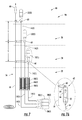
- FIG. 7 is a schematic diagram of an elevation view of an exemplary preconnectorized riser cable installation assembly with a plurality of preconnectorized riser cables being extended from payout reels located at a lower level by a leader with extending features attached to the leader at preset locations;
- FIG. 7A is a detail view of an exemplary pull device assembly which may be attached to the end of the riser cable to facilitate extending the riser cable from the payout reel;
- FIG. 8 is a flowchart illustrating a method of installing a plurality of preconnectorized riser cables from payout reels located at a lower level to FDTs located at distribution levels, according to an exemplary embodiment
- FIG. 9 is a schematic diagram of an elevation view of an exemplary preconnectorized riser cable installation assembly with a plurality of preconnectorized risers being extended from payout reels located at distribution levels by a leader with extending features attached to the leader at preset locations;
- FIG. 10 is a flowchart illustrating a method of installing a plurality of preconnectorized riser cables from payout reels located at distribution levels to a patch panel enclosure located at the lower level, according to an exemplary embodiment
- FIG. 11 is a schematic diagram of a front, perspective view of an exemplary local convergence point (LCP) for use with a fiber optic network in a MDU;
- LCP local convergence point
- FIG. 11A is a schematic diagram of a front, perspective exploded view of the LCP of FIG. 11 having an interior panel removably mountable in the LCP, wherein the interior panel is configured to support optical fiber in a first section of the LCP;
- FIG. 11B is a schematic diagram of a front, perspective exploded view of the LCP of FIG. 11 having an interior panel removably mountable in the LCP, wherein the interior panel is configured to support optical fiber splitting in the second section of the LCP;
- FIG. 11C is a schematic diagram of a front, perspective exploded view of the LCP of FIG. 11 having an interior panel removably mountable in the LCP, wherein the interior panel is configured to support optical fiber splicing in the second section of the LCP;
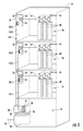
- FIG. 12 is a schematic diagram of front, elevation views of an exemplary patch panel enclosure with a multi-fiber adapter assembly and multiple payout reels removably mounted therein;
- FIG. 13 is a schematic diagram of a front, perspective view of an exemplary FDT having a module with multi-fiber adapters and single fiber adapters and a payout reel removably mounted therein, wherein the FDT is configured to be mounted in-line with and supported by the conduit carrying the riser cable;
- FIG. 14 is a schematic diagram of a front, perspective view of an exemplary FDT having a module assembly with multi-fiber adapters and single fiber adapters pivotably mounted therein and a payout reel removably mounted therein, wherein the FDT is configured to be wall or closet mounted; and
- FIG. 15 is a schematic diagram of the front, elevation perspective view of the FDT of FIG. 14 with the module assembly pivoted to an open position.
- Embodiments disclosed in the detailed description include a fiber optic distribution network for a multi-floor multiple dwelling unit (MDU).
- the network includes a local convergence point (LCP) which may be located in a lower level of the MDU, for example, the basement.
- LCP local convergence point
- the LCP receives a feeder cable that provides optical communication service to the MDU from a service provider.
- One or more preconnectorized riser cables having multi-fiber connectors on each end optically connect to the feeder cable through the LCP.
- the riser cable extends from the LCP to one or more upper distribution levels of the MDU.
- the riser cable is received by a network access point, which may be comprised of a fiber distribution terminal (FDT), a mid-span access point, or the like.
- FDT fiber distribution terminal
- network access point may be used to describe either one or more of the FDT and the mid-span access point.
- FDT, pipe-in-box, and closet box will be used to refer and describe a component of the fiber optic distribution network located at the distribution level for optically connecting the riser cable to the drop cable.
- patch panel enclosure will be used when describing the component of the fiber optic distribution network for optically connecting and extending the riser cable to the LCP and, thereby, to the feeder cable.
- Optically connecting the riser cable and to the subscriber premises may be through tether cables branched off from the riser cable at each distribution level, for example, at a mid-span access point of the riser cable.
- the tether cables may be connected to subscriber premises via one or more drop cables at the network access point.
- an individual riser cable may be extended to the distribution level and optically connect to one or more drop cables routed to the subscriber premises.
- a tether cable may not be branched off of the riser cable at a mid-span access point.
- the drop cable extends to the subscriber premises at the distribution level to provide optical communication service to the subscriber.
- Any riser cable slack may be stored in the FDT, the patch panel enclosure, and/or a separate slack enclosure. Additionally, the riser cable slack may be stored on the payout reel, with the payout reel removably mounted in the FDT, the patch panel enclosure, or the slack enclosure.
- the slack enclosure may be located at or adjacent to the LCP or at one or more of the distribution levels.
- the end of the riser cable would optically connect to the end of one or more drop cables.
- the tether cable and/or the riser cable may terminate in a fiber optic connector and optically connect to the drop cable terminated in a fiber optic connector through a suitable fiber optic adapter.
- the fiber optic adapter may be one that provides for multi-fiber connector to multi-fiber connector interconnection, such as, for example an MTP adapter, or other types of multi-fiber adapters. Additionally or alternatively, the fiber optic adapter may be one that provides for single fiber connector to single fiber connector interconnection, for example an SC adapter, or other types of single fiber adapters.
- the fiber optic adapters may have dual shutters, one on each end of the adapter.
- the shutters are adapted to automatically close against the end of the adapter when a fiber optic connector is not inserted in that end of the adapter. In this manner, the shutters may provide sealing of the adapter against the environment, keeping the adapter protected and clean when not in use.
- the adapter may be keyed up and down to coordinate with the polarity of the connectors.
- the adapters may be mounted in a cassette or module which is removably mounted in the network access point. Alternatively, the adapter may be removably mounted to a panel which may be removably mounted in the network access point.
- the FDT and/or the patch panel enclosure may act as or be a transition box having one or more removably mounted fiber optic adapters configured to receive one or more optical fibers of a riser cable to provide optical communication service from a service provider to a subscriber premises.
- the transition box may have one or more removably mounted payout reels storing the slack of the riser cable or cables paid out in the MDU.
- FIGS. 1-6 illustrate exemplary embodiments of fiber optic networks in an MDU 10 .
- FIGS. 1-5 are schematic diagrams of a perspective elevation views of the MDU 10 with an exemplary fiber optic networks 12 , 112 , 212 , 312 , 412 installed therein, extending to distribution levels in the MDU 10 .
- FIG. 6 is a schematic diagram of a bundled drop extending to a subscriber premises at a distribution level of the MDU 10 .
- a distribution level may be designated for one of the floors of the MDU 10 , or may be designated for any combination of a number of floors of the MDU 10 , or for any portion of a floor of the MDU 10 .
- FIGS. 1-5 are schematic diagrams of a perspective elevation views of the MDU 10 with an exemplary fiber optic networks 12 , 112 , 212 , 312 , 412 installed therein, extending to distribution levels in the MDU 10 .
- FIG. 6 is a schematic diagram of a bundled drop extending
- one or more of the riser cables 14 are shown connecting to a local convergence point (LCP) 40 through a patch panel enclosure 20 .
- LCP local convergence point
- the one or more riser cables 14 may connect directly to the LCP 40 without the patch panel enclosure 20 .
- a riser cable 14 with pre-set mid-span access points 16 extends from a payout reel 18 .
- the mid-span access point 16 may comprise a FlexNAP System, as commercially available from Corning Cable Systems LLC, or other type of connection or system that provides for the separation of one or more optical fibers from the riser cable 14 .
- the riser cable 14 pays out from a payout reel 18 .
- the payout reel 18 is removably mounted in a patch panel enclosure 20 .
- the fiber optic network 12 may have any number of distribution levels.
- the riser cable 14 is preconnectorized with multi-fiber connectors 30 , 32 at each end of the riser cable 14 .
- the patch panel enclosure 20 has a multi-fiber-to-multi-fiber adapter assembly 34 which receives a first multi-fiber connector 30 .
- a distribution cable 36 preconnectorized with a multi-fiber connector 38 is received by and connects to the multi-fiber adapter assembly 34 in the patch panel enclosure 20 to establish an optical connection between the riser cable 14 and the distribution cable 36 .
- the distribution cable 36 routes to a local convergence point (LCP) 40 .
- the LCP 40 receives a feeder cable 42 which provides optical communication service to the MDU 10 from a service provider.
- the riser cable 14 pays out from the payout reel 18 such that the riser cable 14 extends generally in an upward direction from the lower level 22 to each ascending distribution level 24 , 26 , 28 in succession with distribution level 28 being the highest distribution level in the MDU 10 .
- the mid-span access points 16 are preset such that they are separated by a distance “X” along the length of the riser cable 14 .
- the distance “X” is preset at the factory to a certain value depending on the distance between adjoining distribution levels 24 , 26 .
- the distance “X” may be set at any desired distance, as non-limiting examples, 10 feet, 12 feet, 14 feet, 15 feet, and the like.
- the preset mid-span access points will align, generally, with each distribution level 24 , 26 of the MDU 10 .
- the one exception to this may be the highest distribution level 28 , since the end of the riser cable 14 would extend to that level and and would not have a mid-span access point.
- Any riser cable 14 slack due to the presetting of the distance “X” or otherwise, may be stored on the payout reel 18 , in the patch panel enclosure 20 , the LCP 40 , and/or a slack enclosure (not shown in FIG. 1 ).
- Slack may also be stored loosely at the lower level 22 , and/or in one ore more fiber distribution terminals 29 located at one or more of the distribution levels 24 , 26 , 28 .
- the payout reel 18 may be removably mounted in the slack housing or may be mounted or located separate from the patch panel enclosure 20 and/or slack enclosure and/or from the FDT 29 at one or more of the distribution levels 24 , 26 , 28 .
- the riser cable 14 may be any number of optical fibers, as non-limiting examples, 6, 8, 12 or 24 fibers. At each mid-span access point 16 , certain of the optical fibers may be separated or furcated out from the riser cable 14 in a FDT 29 located at the distribution level 24 , 26 . As non-limiting examples, 6, 8 or 12 fibers may be furcated out from the riser cable 14 and terminated with the second multi-fiber connector 32 . At the highest distribution level 28 , the optical fibers remaining in the riser cable 14 after furcating out the optical fibers at lower distribution levels 24 , 26 are terminated with the second multi-fiber connector 32 .
- the second multi-fiber connector 32 may be received by a multi-fiber adapter assembly 34 removably mounted in the FDT 29 at the distribution level 24 , 26 , 28 .
- the multi-fiber adapter assembly 34 may be removably mounted in a connector module or panel (not shown in FIG. 1 ), which may be removably mounted in the FDT 29 .
- a multi-fiber bundled drop cable 44 preconnectorized with a multi-fiber connector 38 is received by and connects to the multi-fiber adapter assembly 34 , or the connector module, as the case may be, in the FDT 29 located at the distribution reel 24 , 26 , 28 .
- the multi-fiber bundled drop cable 44 routes to one or more drop boxes 46 associated with subscriber premises 48 located at the distribution level 24 , 26 , 28 .
- One or more optical fiber separates from the multi-fiber bundled drop cable 44 at the drop box 46 and extends to the subscriber premises 48 . In this manner, optical communication service is provided to the subscriber premises 48 .
- one or more connectorized harnesses or jumpers may be connected between the multi-fiber adapters in the multi-fiber adapter assembly 34 and extended to single fiber adapters (not shown in FIG. 1 ).
- connectorized single fiber drop cables may connect to the harnesses or jumpers to establish optical connection with the riser cable 14 , and ultimately to the subscriber premises 48 .
- FIG. 2 is a schematic diagram of a perspective elevation view the MDU 10 with an exemplary fiber optic network 112 installed therein.
- the riser cable 14 with pre-set mid-span access points 16 extends from a payout reel 18 in a separate slack enclosure 50 located at the highest distribution level 28 to the other distribution levels 24 , 26 and the the lower level 22 .
- the fiber optic network 112 is similar to fiber optic network 12 shown on FIG. 1 , and, therefore, the aspects and/or components of the fiber optic network 112 described with respect to FIG. 1 will not be described again with respect to FIG. 2 .
- FIG. 1 In FIG.
- the payout reel 18 is removably mounted in the slack enclosure 50 located at the highest level 28 instead of the patch panel enclosure 20 .
- the riser cable 14 pays out from the payout reel 18 such that the riser cable 14 extends generally in a downward direction from the highest distribution level 28 to each descending distribution level 26 , 24 in succession, and to the patch panel enclosure 20 .
- the patch panel enclosure 20 includes a multi-fiber adapter assembly 34 but may not include the payout reel 18 since that is located at the highest distribution level 28 in fiber optic network 112 .
- the multi-fiber adapter assembly 34 in the patch panel enclosure 20 receives the first multi-fiber connector 30 and optically connects it with the multi-fiber connector 38 of the distribution cable 36 to establish an optical connection between the riser cable 14 and the distribution cable 36 as described above with respect to FIG. 1 .
- FIG. 3 is a schematic diagram of a perspective elevation view of the MDU 10 with an exemplary fiber optic network 212 installed therein.
- the riser cable 14 with pre-set mid-span access points 16 extends from the payout reel 18 in the FDT 29 located at the highest distribution level 28 to the other distribution levels 24 , 26 .
- the fiber optic network 212 is similar to fiber optic network 12 shown on FIG. 1 and the fiber optic network 112 shown on FIG. 2 and, therefore, the aspects and/or components of the fiber optic network 212 described with respect to FIG. 1 and/or FIG. 2 will not be described again with respect to FIG. 3 .
- FIG. 1 the fiber optic network 112
- the payout reel 18 is removably mounted in the FDT 29 located at the highest distribution level 28 instead of the slack enclosure 50 , as described with respect to FIG. 2 .
- the slack enclosure 50 is not needed at the highest distribution level 28 conserving space.
- the paying out and installation of the riser cable 14 may be the same as described with respect to FIG. 2 .
- FIG. 4 is a schematic diagram of a perspective elevation view of the MDU 10 with an exemplary fiber optic network 312 installed therein.
- a plurality of riser cables 14 ( 1 ), 14 ( 2 ), 14 ( 3 ) each extend from a separate payout reel 18 ( 1 ), 18 ( 2 ), 18 ( 3 ) in the patch panel enclosure 20 and extending to respective ones of the distribution levels 24 , 26 , 28 .
- Each riser cable 14 ( 1 ), 14 ( 2 ), 14 ( 3 ) pays out from respective payout reels 18 ( 1 ), 18 ( 2 ), 18 ( 3 ).
- the respective payout reel 18 ( 1 ), 18 ( 2 ), 18 ( 3 ) is removably mounted in the patch panel enclosure 20 .
- the riser cables 14 ( 1 ), 14 ( 2 ), 14 ( 3 ) extend generally in an upward direction from the lower level 22 to separate ascending distribution level 24 , 26 , 28 . In this manner, a separate riser cable 14 provides optical service to a separate distribution level 24 , 26 , 28 .
- Each of the riser cables 14 ( 1 ), 14 ( 2 ), 14 ( 3 ) terminates with respective second multi-fiber connectors 32 ( 1 ), 32 ( 2 ), 32 ( 3 ) which are received by and connected to the respective multi-fiber adapter assembly 34 in the FDT 29 located at the distribution levels 24 , 26 , 28 .
- the riser cables 14 ( 1 ), 14 ( 2 ), 14 ( 3 ) extend from each of the payout reels 18 ( 1 ), 18 ( 2 ), 18 ( 3 ) to the multi-fiber adapter assembly 34 located at the patch panel enclosure 20 .
- the first multi-fiber connector 30 ( 1 ), 30 ( 2 ), 30 ( 3 ) of each respective riser cable 14 ( 1 ), 14 ( 2 ), 14 ( 3 ) is received by and connects to the multi-fiber adapter assembly 34 in the patch panel enclosure 20 .
- the distribution cable 36 preconnectorized with a multi-fiber connector 38 is received by and connects to the multi-fiber adapter assembly 34 in the patch panel enclosure 20 to establish an optical connection between the riser cables 14 ( 1 ), 14 ( 2 ), 14 ( 3 ) and the distribution cable 36 .
- the distribution cable 36 routes to the LCP 40 .
- FIG. 5 is a schematic diagram of a perspective elevation view of the MDU 10 with an exemplary fiber optic network 412 installed therein.
- the plurality of riser cables 14 ( 1 ), 14 ( 2 ), 14 ( 3 ) each extend from separate, respective FDTs 29 located on one of the distribution levels 24 , 26 , 28 to the patch panel enclosure 20 .
- the fiber optic network 412 is similar to fiber optic network 312 shown on FIG. 4 , and, therefore, the aspects and/or components of the fiber optic network 312 described with respect to FIG. 4 will not be described again with respect to FIG. 5 .
- Each riser cable 14 ( 1 ), 14 ( 2 ), 14 ( 3 ) pays out from respective payout reels 18 ( 1 ), 18 ( 2 ), 18 ( 3 ).
- riser cable 14 ( 1 ), 14 ( 2 ), 14 ( 3 ) After the necessary length of riser cable 14 ( 1 ), 14 ( 2 ), 14 ( 3 ) is paid out, the payout reel 18 ( 1 ), 18 ( 2 ), 18 ( 3 ) is removably mounted in separate, respective FDTS 29 located at respective distribution levels 24 , 26 , 28 .
- the riser cables 14 ( 1 ), 14 ( 2 ), 14 ( 3 ) extend generally in a downward direction from the respective FDTs 29 located at respective distribution levels 24 , 26 , 28 to the lower level 22 . In this manner, a separate riser cable 14 provides optical service to a separate distribution level 24 , 26 , 28 .
- Each of the riser cables 14 ( 1 ), 14 ( 2 ), 14 ( 3 ) terminates with respective second multi-fiber connectors 32 ( 1 ), 32 ( 2 ), 32 ( 3 ) which are received by and connected to the respective multi-fiber adapter assembly 34 in the FDT 29 located at the distribution levels 24 , 26 , 28 .
- the first multi-fiber connector 30 ( 1 ), 30 ( 2 ), 30 ( 3 ) of each respective riser cable 14 ( 1 ), 14 ( 2 ), 14 ( 3 ) is received by and connects to the multi-fiber adapter assembly 34 in the patch panel enclosure 20 .
- the distribution cable 36 preconnectorized with a multi-fiber connector 38 is received by and connects to the multi-fiber adapter assembly 34 in the patch panel enclosure 20 to establish an optical connection between the riser cables 14 ( 1 ), 14 ( 2 ), 14 ( 3 ) and the distribution cable 36 .
- the distribution cable 36 routes to the LCP 40 .
- the multi-fiber bundled drop cable 44 extends from the FDT 29 at the distribution level 24 , 26 , 28 to drop box 46 associated with the and located at the subscriber premises 48 .
- the multi-fiber bundled drop cable 44 includes multiple fiber optic cables 52 retained together by one or more helically wrapped external binders 54 .
- One or more of the multiple fiber optic cables is separated from the multi-fiber bundled drop cable 44 by removing the multiple fiber optic cable from the retainage of the one or more external binders.
- the separated fiber optic cable 52 may then extend to the subscriber premises 48 .
- FIG. 7 is a schematic diagram of an elevation view of an exemplary preconnectorized riser cable installation assembly 56 with a plurality of preconnectorized riser cables 14 ( 1 ), 14 ( 2 ), 14 ( 3 ) being extended from respective payout reels 18 ( 1 ), 18 ( 2 ), 18 ( 3 ) located at a lower level 22 by a leader 58 with extending features 60 attached to the leader 58 at preset locations at a distance “Y” along the length of the leader 58 .
- the extending feature 60 may be any type of loop, hook, swivel, or the like, configured to attach to the second multi-fiber connectors 32 ( 1 ), 32 ( 2 ), 32 ( 3 ), or to some type of pull device attached to the second multi-fiber connectors 32 ( 1 ), 32 ( 2 ), 32 ( 3 ) to provide for safely and effectively paying out the riser cables 14 ( 1 ), 14 ( 2 ), 14 ( 3 ).
- FIG. 7A is a detail view of a pull device assembly 62 which may be attached to the end of the riser cable 14 to facilitate extending the riser cable 14 from the payout reel 18 .
- the pull device assembly 62 attaches to the riser cable 14 around the second multi-fiber connector 32 enclosing the second multi-fiber connector 32 , boot and a portion of the riser cable 14 .
- the pull device assembly 62 has a swivel end 64 and a body 66 .
- the body 66 may enclose and/or support the second multi-fiber connectors 32 .
- the swivel end 64 is allowed to rotate freely and independently of the body 66 and, therefore, the the second multi-fiber connector 32 and the riser cable 14 .
- the swivel end 64 comprises a hole through which the extending feature 60 inserts.
- the swivel end 64 it is allowed to independently rotate from the rest of the pull device assembly 62 . This independent rotation eliminates twisting of the riser cable 14 and the the second multi-fiber connector 32 .
- the leader 58 is pulled through the MDU 10 particularly in conduit, the leader 58 , the extending feature 60 and the swivel end 64 reduce or may eliminate any induce additional torsional stresses on the riser cable 14 and/or the second multi-fiber connector 32 .
- the distance “Y” is preset to a certain value depending on the distance between adjoining distribution levels 24 , 26 , 28 .
- the distance “Y” may be set at 10 feet, 12 feet, 14 feet, 15 feet, and the like. In this manner, as the leader 58 is pulled through the MDU 10 , riser cables 14 ( 1 ), 14 ( 2 ), 14 ( 3 ) each pays out to a point that will align, generally, with each respective distribution level 24 , 26 , 28 of the MDU 10 .
- Any riser cable 14 slack due to the presetting of the distance “Y” or otherwise, may be stored on the respective payout reel 18 ( 1 ), 18 ( 2 ), 18 ( 3 ) and/or loosely in an patch panel enclosure 20 and/or a slack enclosure (not shown in FIG. 7 ). Additionally, slack may be stored loosely, on the payout reels 18 ( 1 ), 18 ( 2 ), 18 ( 3 ) and/or the FDT 29 at one or more of the distribution levels 24 , 26 , 28 .
- Each second multi-fiber connectors 32 ( 1 ), 32 ( 2 ), 32 ( 3 ), may then be connected to the respective multi-fiber adapter assembly 34 removably mounted in the FDT 29 located at the respective distribution level 24 , 26 , 28 .
- the first multi-fiber connectors 30 ( 1 ), 30 ( 2 ), 30 ( 3 ) attached to respective riser cables 14 ( 1 ), 14 ( 2 ), 14 ( 3 ) may be connected to the respective multi-fiber adapter assembly 34 removably mounted in the patch panel enclosure 20 .
- FIG. 8 is a flowchart illustrating a method of installing a plurality of preconnectorized riser cables 14 ( 1 ), 14 ( 2 ), 14 ( 3 ), from payout reels 18 ( 1 ), 18 ( 2 ), 18 ( 3 ) located at a lower level 22 to FDTs 29 located at upper levels 24 , 26 , 28 according to an exemplary embodiment.
- the payout reels 14 ( 1 ), 14 ( 2 ), 14 ( 3 ) are positioned in the lower level 22 (Step 1000 ).
- a pull device assembly 62 may be attached to the end of each riser cable 14 ( 1 ), 14 ( 2 ), 14 ( 3 ) (Step 1002 ).
- a leader 58 with extending features 60 located at the pre-set distance “Y” along the length of the leader 58 is provided (Step 1004 ).
- the leader may be a 180 pound rated urethane jacketed kevlar.
- the extending features 60 are attached to the end of each riser cable 14 ( 1 ), 14 ( 2 ), 14 ( 3 ), particularly to each pull device assembly 62 if such is provided (Step 1006 ).
- a pull rope or string is attached to the end of the leader 58 through a pull loop 68 (Step 1008 ) and, using the pull rope or string, the leader 58 is pulled to the distribution levels 24 , 26 , 28 of the MDU 10 in an ascending order paying out the riser cables 14 ( 1 ), 14 ( 2 ), 14 ( 3 ) from the respective payout reels 18 ( 1 ), 18 ( 2 ), 18 ( 3 ) (Step 1010 ).
- the pull rope or string may be a 200 pound rated nylon pull string.
- a 50 pound pull tension rated plastic mesh pulling grip may also be used.
- the leader 58 is accessed and the appropriate riser cable 14 ( 1 ), 14 ( 2 ), 14 ( 3 ) for that distribution level 24 , 26 , 28 is extended.
- the appropriate riser cable 14 ( 1 ), 14 ( 2 ), 14 ( 3 ) is disconnected from the extending feature 60 and the second multi-fiber connector 32 ( 1 ), 32 ( 2 ), 32 ( 3 ) to the respective multi-fiber adapter assembly 34 in the FDT 29 at the distribution level 24 , 26 , 28 (Step 1012 ).
- the first multi-fiber connectors 30 ( 1 ), 30 ( 2 ), 30 ( 3 ) may be connected to the multi-fiber adapter assembly 34 located in the patch panel enclosure 20 (Step 1014 ).
- Riser cable 14 slack may be stored in the FDT 29 at the distribution level 24 , 26 , 28 and/or in the payout reels 18 ( 1 ), 18 ( 2 ), 18 ( 3 ) (Step 1016 ).
- the payout reels 18 ( 1 ), 18 ( 2 ), 18 ( 3 ) may be removably mounted in the patch panel enclosure 20 .
- the extending features 60 may be positioned further apart than the spacing between distribution levels 24 , 26 , 28 . If the distribution level is aligned with a floor of the MDU 10 , and the floors are spaced at 12 feet, the extending feature 60 may be spaced at 14 feet.
- the leader 58 and the riser cable 14 ( 3 ) is then extended to the upper-most distribution level 28 .
- An adequate amount of slack of the riser cable 14 ( 3 ), for example, 10 feet of slack, is pulled up and stored in the FDT 29 at the distribution level 28 .
- the riser cable 14 ( 3 ) slack is manually accessed and extended to the FDT 29 and the second multi-fiber connector 32 ( 3 ) connected to the multi-fiber adapter assembly 34 in the FDT 29 . This allows for enough slack of the riser cable 14 ( 3 ) to better facilitate installation. A similar process may then be used with successively descending distribution levels 26 , 24 of the MDU 10 until the installation is complete.
- FIG. 9 is a schematic diagram of an elevation view of an exemplary preconnectorized riser cable installation assembly 70 with a plurality of preconnectorized riser cables 14 ( 1 ), 14 ( 2 ), 14 ( 3 ) being extended from payout reels 18 ( 1 ), 18 ( 2 ), 18 ( 3 ) each located at respective distribution levels 24 , 26 , 28 of the MDU 10 .
- the riser cables 14 ( 1 ), 14 ( 2 ), 14 ( 3 ) by a leader 58 with extending features 60 attached to the leader 58 at preset locations at a distance “Z” along the length of the leader 58 .
- the extending feature 60 may be any type of loop, hook, swivel, or the like, configured to attach to the second multi-fiber connectors 32 ( 1 ), 32 ( 2 ), 32 ( 3 ), or to some type of pull device attached to the second multi-fiber connectors 32 ( 1 ), 32 ( 2 ), 32 ( 3 ) to provide for safely and effectively paying out the riser cables 14 ( 1 ), 14 ( 2 ), 14 ( 3 ).
- the riser cables 14 ( 1 ), 14 ( 2 ), 14 ( 3 ) may be attached to the end of the riser cables 14 ( 1 ), 14 ( 2 ), 14 ( 3 ) to facilitate extending the riser cables 14 ( 1 ), 14 ( 2 ), 14 ( 3 ) from the payout reels 18 ( 1 ), 18 ( 2 ), 18 ( 3 ).
- the distance “Z” is preset to a value, as a nonlimiting example, 6 inches, to allow the leader 58 to be accessed at each succeeding distribution level 24 , 26 , 28 in descending order to attach extending feature 60 to the particular riser cable 14 ( 1 ), 14 ( 2 ), 14 ( 3 ).
- the riser cable 14 ( 3 ) for the highest distribution level 28 is attached to the leader first.
- the riser cable 14 ( 2 ) for then next lower distribution level 26 is attached to the leader 58 .
- the riser cable 14 ( 1 ) for the next lower distribution level 24 is attached to the leader 58 .
- the leader 58 extends to the lower level 22 .
- Any riser cable 14 slack may be stored on the respective payout reel 18 ( 1 ), 18 ( 2 ), 18 ( 3 ) and/or loosely in the FDT 29 and/or a slack enclosure (not shown in FIG. 9 ) at the distribution level 24 , 26 , 28 . Additionally, slack may be stored in the patch panel enclosure 20 .
- Each second multi-fiber connectors 32 ( 1 ), 32 ( 2 ), 32 ( 3 ), may then be connected to the respective multi-fiber adapter assembly 34 removably mounted in the FDT 29 located at the respective distribution level 24 , 26 , 28 .
- first multi-fiber connectors 30 ( 1 ), 30 ( 2 ), 30 ( 3 ) attached to respective riser cables 14 ( 1 ), 14 ( 2 ), 14 ( 3 ) may be connected to the respective multi-fiber adapter assembly 34 removably mounted in the patch panel enclosure 20 .
- FIG. 10 is a flowchart illustrating a method of installing a plurality of preconnectorized riser cables 14 ( 1 ), 14 ( 2 ), 14 ( 3 ) from payout reels 18 ( 1 ), 18 ( 2 ), 18 ( 3 ) located at distribution levels 24 , 26 , 28 of MDU 10 to the patch panel enclosure 20 , according to an exemplary embodiment.
- the payout reels 14 ( 1 ), 14 ( 2 ), 14 ( 3 ) are each positioned at respective distribution levels 24 , 26 , 28 (Step 2000 ).
- a pull device assembly 62 may be attached to the end of each riser cable 14 ( 1 ), 14 ( 2 ), 14 ( 3 ) (Step 2002 ).
- a leader 58 with extending features 60 located at the pre-set distance “Z” along the length of the leader 58 is provided (Step 2004 ).
- the leader may be a 180 pound rated urethan jacketed kevlar.
- a pull rope or string is attached to the pulling loop 68 at the end of the leader 58 (Step 2006 ).
- the pull rope or string may be a 200 pound rated pull string.
- a 50 pound pull tension rated plastic mesh pulling grip may also be used.
- One of the extending features 60 which may be the first extending feature 60 closest to the pulling loop 68 is attached to the riser cable 14 ( 3 ) from the payout reel 18 ( 3 ) located at the highest distribution level 28 in the MDU 10 (Step 2008 ).
- the leader 58 is extended to the next succeeding distribution level 26 , 24 in descending order (Step 2010 ).
- the leader 58 is accessed and the next extending feature 60 is attached to the end of that riser cable 14 ( 2 ), 14 ( 3 ) (Step 2012 ).
- the leader 58 is extended to all of the distribution levels and the riser cable attached in the same manner.
- the leader 58 is extended to the lower level 22 (Step 2014 ).
- the riser cables 14 ( 1 ), 14 ( 2 ), 14 ( 3 ) are disconnected from the leader 58 and each first multi-fiber connector 30 ( 1 ), 30 ( 2 ), 30 ( 3 ) is connected to the multi-fiber adapter assembly 34 in the patch panel 20 enclosure (Step 2016 ).
- Each second multi-fiber connector 32 ( 1 ), 32 ( 2 ), 32 ( 3 ) is connected to respective multi-fiber adapter assemblies 34 in the FDT 29 located at the distribution levels 24 , 26 , 28 (Step 2018 ).
- Riser cable 14 slack may be stored in the FDT 29 at the distribution level 24 , 26 , 28 and/or in the payout reels 18 ( 1 ), 18 ( 2 ), 18 ( 3 ) (Step 2020 ).
- the payout reels 18 ( 1 ), 18 ( 2 ), 18 ( 3 ) may be removably mounted in the FDT 29 . Slack may also be stored in the patch panel enclosure 20 .
- FIG. 11 is a schematic diagram of a front, perspective view of an exemplary LCP 40 for use with a fiber optic network in a MDU 10 .
- the LCP 40 comprises an enclosure 72 with a door 74 hingedly attached to the enclosure 72 .
- the door 74 closes to restrict and/or prohibit access to the interior 76 of the enclosure 72 and the components mounted therein, and opens to allow access to the interior 76 and the components mounted therein.
- a swingable adapter panel 78 mounts in the interior 76 .
- the adapter panel 78 has a first side 80 (not visible in FIG. 11 ) and a second side 82 to provide connections of optical fibers 83 between a feeder side and a distribution side.
- Pivot points 96 positioned at the top and bottom of the interior 76 allow the adapter panel to swing to provide access to the first side 80 or the second side 82 depending on the positioning of the adapter panel 78 . Additionally, the adapter panel is lockable in one or more positions.
- the adapter panel 78 splits the interior 76 into a first section 84 and a second section 86 .
- the LCP 40 is flexible such that either or both the first section 84 or the second section 86 can be configured to support feeder side optical fiber 83 management and/or connections, and/or distribution side optical fiber 83 management and/or connections.
- the adapter panel 78 has a connection field 88 that supports multi-fiber adapters and connections, single fiber adapters and connections as well as pass-through adapters and connection.
- the feeder cable 42 is shown as entering the LCP 40 at the bottom into the first section 84 and connecting to splice trays 92 .
- a continuing section 42 ( 1 ) of the feeder cable 42 extends from the bottom of the second side 86 to further provide optical connection from the service provider to other areas of the MDU 10 and/or to other MDU's and/or facilities.
- the distribution cable 36 extends from the top of the first section 84 .
- the distribution cable 36 optically connects to one or more riser cables 14 , which may be through a multi-fiber adapter assembly 34 in a patch panel housing 20 .
- One or more splitters 94 may also be mounted in the LCP 40 to split the optical signal carried by the feeder cable 42 into multiple optical signals for distribution.
- Fiber routing guides 98 and fiber management guides 100 may also be mounted in the first section 84 and/or the second section 86 .
- FIGS. 11A, 11B and 11C are schematic diagrams of front, perspective, exploded views of the LCP 40 illustrating interior panels 102 ( 1 ), 102 ( 2 ), 102 ( 3 ) which may be used in the LCP 40 .
- the interior panels 102 ( 1 ), 102 ( 2 ), 102 ( 3 ) are interchangeable and allow the LCP 40 enclosure 72 to be easily reconfigured at the factory or in the field. This allows the enclosure 72 to be configured and reconfigured to support multiple applications and changing subscriber situations. In this manner, the interior panels 102 ( 1 ), 102 ( 2 ), 102 ( 3 ) can support, without limitation, fiber splicing, multiple splitter form factors, cable entries and other various modifications or arrangements of the LCP 40 .
- interior panels 102 ( 1 ), 102 ( 2 ), 102 ( 3 ) can be installed on the either the first section 84 or second section 86 of the interior 76 using any type of fasteners 104 , such as, without limitation, screws, latches and the like allowing for removable attachment.
- FIG. 11A illustrates an interior panel 102 ( 1 ) removably mountable to the enclosure 72 in the interior 76 in the first section 84 configured to support optical fiber splicing having splice trays 92 and optical fiber management guides 100 .
- FIG. 11B illustrates an interior panel 102 ( 2 ) removably mountable to the enclosure 72 in the interior 76 in the second section 86 configured to support optical fiber splitting having splitters 94 and optical fiber management guides 100 .
- FIG. 11C illustrates an interior panel 102 ( 2 ) removably mountable to the enclosure 72 in the interior 76 in the second section 86 configured to support optical fiber splicing having splice trays 92 and optical fiber management guides 100 .
- an interior panel 102 removably mountable to the enclosure 72 in the interior 76 in the first section 84 may be configured to support optical fiber splitting having splitters 94 and optical fiber management guides 100 .
- the interior panels 102 may be configured to support any type of function or component, as examples, without limitation, furcation devices, ribbon fan-out bodies, wave division multiplexing, coarse wave division multiplexing and others.
- the LCP 40 provides for a smaller form factor while allow a high density of optical fiber connections for distribution of optical service to the MDU 10 . Additionally, the LCP 40 allows for various options for feeder and distribution cables and of multiple splitters including, without limitation, at least five 1 ⁇ 32 splitters. The LCP 40 can also function as a demarcation point providing 1 ⁇ 1 input to output connections.
- FIG. 12 is a schematic diagram of front, elevation views of an exemplary patch panel enclosure 20 with a multi-fiber adapter assembly 34 and multiple payout reels 18 removably mounted therein.
- the patch panel enclosure 20 has a door 104 hingedly attached thereto.
- the door 104 closes to restrict and/or prohibit access to the interior 106 of the patch panel enclosure 20 and the components mounted therein, and opens to allow access to the interior 106 and the components mounted therein.
- a multi-fiber adapter assembly 34 and multiple payout reels 18 ( 1 ), 18 ( 2 ), 18 ( 3 ), 18 ( 4 ), are shown mounted in the interior 106 .
- the riser cables 14 ( 1 ), 14 ( 2 ), 14 ( 2 ), 14 ( 2 ) are shown as having been paid out from the payout reels 18 ( 1 ), 18 ( 2 ), 18 ( 3 ), 18 ( 4 ) which are now being used to store riser cable 14 ( 1 ), 14 ( 2 ), 14 ( 2 ), 14 ( 2 ) slack.
- the payout reels 18 ( 1 ), 18 ( 2 ), 18 ( 3 ), 18 ( 4 ) are shown as being collapsed to a smaller form factor allowing for storing in the patch panel enclosure 20 .
- the first multi-fiber connectors 30 ( 1 ), 30 ( 2 ), 30 ( 3 ), 30 ( 4 ) route and connect to one side of the multi-fiber adapter assembly 34 .
- the distribution cable 36 connects to the other end of the multi-fiber adapter assembly 34 and extends from the bottom of the patch panel enclosure 20 .
- Mounting holes 108 allow the patch panel enclosure 20 to be mounted as non-limiting examples, to a wall or rack.
- FIG. 13 is a schematic diagram of a front, perspective view of a FDT 129 having a payout reel 18 and an adapter module assembly 110 with an adapter module 112 and a multi-fiber adapter assembly 34 removably mounted therein.
- the FDT 129 is configured to be mounted in-line with and supported by conduit 113 carrying the riser cable 14 and may be mounted at one or more distribution levels 24 , 26 , 28 .
- the FDT 129 has an enclosure 114 with a door 116 hingedly attached thereto. The door 116 closes to restrict and/or prohibit access to the interior 118 of the FDT 129 and the components mounted therein, and opens to allow access to the interior 118 and the components mounted therein.
- FIG. 13 is a schematic diagram of a front, perspective view of a FDT 129 having a payout reel 18 and an adapter module assembly 110 with an adapter module 112 and a multi-fiber adapter assembly 34 removably mounted therein.
- the FDT 129 is configured to be mounted
- the adapter module assembly 110 is shown mounted to the door 116 in the interior 118 .
- the adapter module assembly 110 comprises a connector panel 120 to which the adapter module 112 and the multi-fiber adapter assembly 34 attach.
- the multi-fiber adapter assembly 34 has multi-fiber adapters 122 .
- the adapter module 112 has multiple single fiber adapters 124 . In this manner, the adapter module assembly 110 can receive and connect the riser cable 14 to drop cables 44 extending to subscriber premises 48 located on the distribution levels 24 , 26 , 28 .
- Routing guides 126 route and manage fiber optic cables may be mounted to the door 116 in the interior 118 in addition to the adapter module assembly 110 .
- the door 116 has a flange 128 having a tool lock mechanism 130 and a pad lock hole 132 .
- a flange 134 on the enclosure 114 has a tool lock receiver 136 and pad lock hole 138 , which mate with the tool lock mechanism 130 and a pad lock hole 132 when the door 116 is closed to provide for locking the FDT 129 .
- the riser cable 14 is shown as having been paid out from the payout reel 18 which is now being used to store riser cable 14 slack.
- the payout reel 18 is shown as being collapsed to a smaller form factor allowing for storing in the FDT 129 .
- FIG. 14 is a schematic diagram of a front, perspective view of an exemplary FDT 229 having a payout reel 18 removably mounted therein and an adapter module assembly 210 pivotably mounted therein.
- the FDT 229 has an enclosure 214 with a door 216 hingedly attached thereto, and may be located at one or more distribution levels 24 , 26 , 28 .
- the door 216 closes to restrict and/or prohibit access to the interior 218 of the FDT 229 and the components mounted therein, and opens to allow access to the interior 218 and the components mounted therein.
- the adapter module assembly 210 has a cradle 136 adapted to removably hold one or more adapter modules 112 or adapter panels.
- the cradle 136 has a slack storage area 138 for storing the slack of drop cables 44 extending to subscriber premises 48 located at the distribution level 24 , 26 , 28 .
- a routing guide 240 connecting to and extending from the cradle provides for drop cable 44 routing and management in the FDT 229 .
- One or more mounting ears 142 extend from the enclosure 214 allowing the enclosure 214 to be mounted to a wall, for example in a closet, at the distribution level 24 , 26 , 28 .
- the door 216 has a flange 228 having a tool lock mechanism 130 and a pad lock hole 132 .
- a flange 234 on the enclosure 214 has a tool lock receiver 136 and pad lock hole 138 , which mate with the tool lock mechanism 130 and a pad lock hole 132 when the door 116 is closed to provide for locking the FDT 229 .
- the riser cable 14 is shown as having been paid out from the payout reel 18 which is now being used to store riser cable 14 slack.
- the payout reel 18 is shown as being collapsed to a smaller form factor allowing for storing in the FDT 229 .
- FIG. 15 is a schematic diagram of the front, elevation perspective view of the FDT 229 with the adapter module assembly 210 pivoted to an open position.
- the adapter module assembly 210 has a pivot assembly 144 connected to the bottom of the enclosure 214 .
- the pivot assembly 144 is illustrated as a cradle bracket 146 and a cradle hinge 148 .
- the pivot assembly 144 can be any mechanical or structural design that allows the adapter module assembly 210 to pivot.
- Sealing feature 150 allows the riser cable 14 and drop cables 44 to enter the enclosure 214 while maintaining the FDT 229 in an environmentally sealed condition.
- One or more strain relief brackets 152 provide strain relief for the riser cable 14 and drop cables 44 in the FDT 229 .
Abstract
Description
Claims (14)
Priority Applications (1)
| Application Number | Priority Date | Filing Date | Title |
|---|---|---|---|
| US13/613,759 US9547144B2 (en) | 2010-03-16 | 2012-09-13 | Fiber optic distribution network for multiple dwelling units |
Applications Claiming Priority (3)
| Application Number | Priority Date | Filing Date | Title |
|---|---|---|---|
| US31435810P | 2010-03-16 | 2010-03-16 | |
| PCT/US2011/028650 WO2011116081A1 (en) | 2010-03-16 | 2011-03-16 | Fiber optic distribution network for multiple dwelling units |
| US13/613,759 US9547144B2 (en) | 2010-03-16 | 2012-09-13 | Fiber optic distribution network for multiple dwelling units |
Related Parent Applications (1)
| Application Number | Title | Priority Date | Filing Date |
|---|---|---|---|
| PCT/US2011/028650 Continuation WO2011116081A1 (en) | 2010-03-16 | 2011-03-16 | Fiber optic distribution network for multiple dwelling units |
Publications (2)
| Publication Number | Publication Date |
|---|---|
| US20130034336A1 US20130034336A1 (en) | 2013-02-07 |
| US9547144B2 true US9547144B2 (en) | 2017-01-17 |
Family
ID=47627004
Family Applications (1)
| Application Number | Title | Priority Date | Filing Date |
|---|---|---|---|
| US13/613,759 Active 2032-11-02 US9547144B2 (en) | 2010-03-16 | 2012-09-13 | Fiber optic distribution network for multiple dwelling units |
Country Status (1)
| Country | Link |
|---|---|
| US (1) | US9547144B2 (en) |
Families Citing this family (19)
| Publication number | Priority date | Publication date | Assignee | Title |
|---|---|---|---|---|
| EP2344915A4 (en) | 2008-10-09 | 2015-01-21 | Corning Cable Sys Llc | Fiber optic terminal having adapter panel supporting both input and output fibers from an optical splitter |
| CN103430072B (en) | 2010-10-19 | 2018-08-10 | 康宁光缆系统有限责任公司 | For the transformation box in the fiber distribution network of multitenant unit |
| US8913867B2 (en) * | 2011-11-21 | 2014-12-16 | Opterna Technology Limited | Fiber optic collector and terminal assemblies |
| US9219546B2 (en) | 2011-12-12 | 2015-12-22 | Corning Optical Communications LLC | Extremely high frequency (EHF) distributed antenna systems, and related components and methods |
| US10110307B2 (en) | 2012-03-02 | 2018-10-23 | Corning Optical Communications LLC | Optical network units (ONUs) for high bandwidth connectivity, and related components and methods |
| NZ713567A (en) * | 2013-04-24 | 2018-11-30 | Prysmian Spa | User module and method for connecting an external communication network |
| US9284751B2 (en) | 2013-06-05 | 2016-03-15 | Chanell Commercial Corp. | High security locking assembly for above-ground fiber optic/cable network enclosures |
| WO2016191094A1 (en) * | 2015-05-27 | 2016-12-01 | 3M Innovative Properties Company | Fiber management assemblies and network interface devices incorporating such assemblies |
| US10359590B2 (en) | 2016-04-04 | 2019-07-23 | Opterna Technology Limited | Fiber optic cable deployment assemblies, systems, and methods |
| US10859781B2 (en) | 2016-09-20 | 2020-12-08 | Clearfield, Inc. | Optical fiber distribution systems and components |
| US10606006B2 (en) * | 2016-09-20 | 2020-03-31 | Clearfield, Inc. | Optical fiber distribution systems and components |
| US10887018B2 (en) | 2016-11-02 | 2021-01-05 | CommScpe Technologies LLC | Fiber optic network architecture with parallel indexed and non-indexed fiber paths |
| US10317639B2 (en) | 2016-11-11 | 2019-06-11 | CommScope Connectivity Belgium BVBA | Fiber optic network architecture |
| WO2018132576A1 (en) * | 2017-01-12 | 2018-07-19 | Commscope Technologies Llc | Optical tapping in an indexing architecture |
| US10310206B2 (en) * | 2017-05-22 | 2019-06-04 | Go!Foton Holdings, Inc. | Apparatus for cable routing |
| EP4097523A1 (en) * | 2020-01-29 | 2022-12-07 | Corning Research & Development Corporation | Preconnectorized distribution cable assemblies and methods of making using a pull string |
| US10998703B1 (en) * | 2020-02-26 | 2021-05-04 | International Business Machines Corporation | Cable routing and bend radius defining tool |
| EP3936913A1 (en) * | 2020-07-10 | 2022-01-12 | Corning Research & Development Corporation | Fiber-optic apparatus |
| WO2022226895A1 (en) * | 2021-04-29 | 2022-11-03 | Corning Research & Development Corporation | Preconnectorized optical distribution cable assemblies and corresponding methods of deployment |
Citations (500)
| Publication number | Priority date | Publication date | Assignee | Title |
|---|---|---|---|---|
| US1280393A (en) | 1917-03-03 | 1918-10-01 | John T Cannon | Line hook and holding means. |
| US1703255A (en) | 1927-03-23 | 1929-02-26 | Fred W Wagner | Attachment for treads for auto chains |
| US2003147A (en) | 1933-08-25 | 1935-05-28 | Gen Electric | Electric vacuum cleaner |
| US2044073A (en) | 1935-06-19 | 1936-06-16 | George H Hurley | Clothesline reel |
| US2131408A (en) | 1936-12-29 | 1938-09-27 | Herbert C Murrer | Tackle box tray |
| US2428149A (en) | 1943-10-18 | 1947-09-30 | Farnsworth Television & Radio | Impulse generator |
| US2681201A (en) | 1950-05-05 | 1954-06-15 | Marshall F Grunwald | Tackle box and fixture therefor |
| US2984488A (en) | 1958-06-09 | 1961-05-16 | Stewart W Kirchner | Artistic game apparatus |
| US3054994A (en) | 1958-07-30 | 1962-09-18 | Haram Arthur Carsten | Visual signal generation and electrical outlet control means therefor |
| US3204867A (en) | 1963-06-04 | 1965-09-07 | Rockford Coca Cola Bottling Co | Bottle storage device |
| US3435124A (en) | 1966-02-07 | 1969-03-25 | William H Channell | Pedestal and underground terminals for buried cable systems |
| FR2123728A5 (en) | 1971-01-29 | 1972-09-15 | App Const | |
| US3880390A (en) | 1973-11-08 | 1975-04-29 | Dynagraphic Merchandising Corp | Universal pegboard |
| US4006540A (en) | 1975-09-19 | 1977-02-08 | Lemelson Jerome H | Filament winding craft |
| US4012010A (en) | 1975-12-02 | 1977-03-15 | Friedman Robert W | Thread dispenser |
| US4073560A (en) | 1976-03-08 | 1978-02-14 | International Telephone And Telegraph Corporation | Electrical connector |
| US4123012A (en) | 1977-05-12 | 1978-10-31 | Hough W Colton | Cord holder |
| US4177961A (en) | 1978-06-23 | 1979-12-11 | Excel Plastic Products, Inc. | Extension cord holder |
| US4210380A (en) | 1978-11-08 | 1980-07-01 | Western Electric Company, Inc. | Cable connector housing having strain relief system |
| USD257613S (en) | 1978-06-23 | 1980-12-09 | Excel Plastics Products, Inc. | Extension cord holder |
| US4244544A (en) | 1978-05-30 | 1981-01-13 | Ford Motor Company | Holders for cables and conduits |
| US4261529A (en) | 1980-01-14 | 1981-04-14 | Sandberg Robert G | Device for winding and storage of ropes and the like |
| US4261644A (en) | 1978-11-30 | 1981-04-14 | The United States Of America As Represented By The Secretary Of The Navy | Method and article of manufacturing an optical fiber connector |
| JPS59107317A (en) | 1982-12-13 | 1984-06-21 | Nippon Telegr & Teleph Corp <Ntt> | Wiring method in connecting box for optical cable |
| US4480449A (en) | 1981-06-11 | 1984-11-06 | Whirlpool Corporation | Automatic liquid level control for automatic washers |
| US4497457A (en) | 1983-08-18 | 1985-02-05 | Harvey William O | Line holder |
| US4502754A (en) | 1982-01-19 | 1985-03-05 | Nippon Electric Co., Ltd. | Optical fiber interconnection mechanism |
| US4506698A (en) | 1983-07-07 | 1985-03-26 | Suncast Corporation | Garden hose storage apparatus |
| US4524384A (en) | 1983-04-21 | 1985-06-18 | Gbc Closed Circuit Tv Corp. | Video and audio security system |
| USD281574S (en) | 1983-11-18 | 1985-12-03 | O'hara Ii Joseph T | Cord reel |
| US4579310A (en) | 1983-12-17 | 1986-04-01 | All-States Inc. | Guides for organizing wires |
| US4586675A (en) | 1984-08-16 | 1986-05-06 | Brown Robert L | Tangle free cord holder |
| US4595255A (en) | 1983-08-24 | 1986-06-17 | Fiberlan, Inc. | Optical fiber wiring center |
| US4611887A (en) | 1983-02-24 | 1986-09-16 | Amp Incorporated | Fiber optic connector assembly and wall outlet thereof |
| US4697873A (en) | 1981-04-03 | 1987-10-06 | Lignes Telegraphiques Et Telephoniques | Device for protecting optical fibers freed at the end of a cable element |
| US4736100A (en) | 1986-07-31 | 1988-04-05 | Amp Incorporated | Optical loop attenuator simulating an optical system |
| US4747020A (en) | 1986-05-16 | 1988-05-24 | Adc Telecommunications, Inc. | Wire distribution apparatus |
| WO1988005925A1 (en) | 1987-02-03 | 1988-08-11 | American Telephone & Telegraph Company | Duplex optical fiber connector |
| US4778125A (en) | 1987-07-10 | 1988-10-18 | Hu Dye Chung | Extension cord winding device |
| US4806814A (en) | 1987-11-16 | 1989-02-21 | Sundstrand Corporation | Half-wave rotary rectifier assembly |
| US4810054A (en) | 1985-09-12 | 1989-03-07 | Kokusai Denshin Denwa Kabushiki Kaisha | Fusion splicing method for optical fibers |
| US4824193A (en) | 1985-07-26 | 1989-04-25 | Matsushita Electric Industrial Co., Ltd. | Holographic multiplexer/demultiplexer and its manufacturing method |
| US4836479A (en) | 1988-02-04 | 1989-06-06 | Adams John H | Hose storing and dispensing rack |
| WO1989005989A1 (en) | 1987-12-23 | 1989-06-29 | British Telecommunications Public Limited Company | Mounting assembly for optical equipment |
| US4844573A (en) | 1987-05-22 | 1989-07-04 | Aster Corporation | Electro-optical converter including ridgid support for optical fiber coupler, telephone set using the coupler and method of making same |
| US4884863A (en) | 1989-03-06 | 1989-12-05 | Siecor Corporation | Optical fiber splicing enclosure for installation in pedestals |
| US4900118A (en) | 1987-05-22 | 1990-02-13 | Furukawa Electric Co., Ltd. | Multiple-fiber optical component and method for manufacturing of the same |
| US4900123A (en) | 1988-08-29 | 1990-02-13 | Gte Products Corporation | 1550 nm fiber distribution panel |
| US4948220A (en) | 1988-06-20 | 1990-08-14 | Societe Anonyme De Telecommunications | Module for distributing and connecting optical fibers |
| US4961623A (en) | 1989-09-05 | 1990-10-09 | Siecor Corporation | Preterminated optical cable |
| US4979749A (en) | 1989-10-10 | 1990-12-25 | Onanian Richard A | Multi-use number board |
| EP0409390A2 (en) | 1989-07-17 | 1991-01-23 | Telephone Cables Limited | Junction box for optical communications cords and gland assembly for cord |
| EP0410622A2 (en) | 1989-07-26 | 1991-01-30 | AT&T Corp. | Buffered optical fiber having a strippable buffer layer |
| US4995688A (en) | 1989-07-31 | 1991-02-26 | Adc Telecommunications, Inc. | Optical fiber distribution frame |
| EP0415647A2 (en) | 1989-08-31 | 1991-03-06 | AT&T Corp. | Local area network architecture |
| US5007701A (en) | 1989-06-29 | 1991-04-16 | Windsor Communications, Inc. | Splice closure apparatus |
| US5023646A (en) | 1985-12-27 | 1991-06-11 | Minolta Camera Kabushiki Kaisha | Automatic focus detection system |
| US5048916A (en) | 1982-09-07 | 1991-09-17 | Amp Incorporated | Fiber optic connection system |
| US5048926A (en) | 1988-02-29 | 1991-09-17 | Nikon Corporation | Illuminating optical system in an exposure apparatus |
| US5066149A (en) | 1990-09-11 | 1991-11-19 | Adc Telecommunications, Inc. | Splice tray with slack take-up |
| US5071211A (en) | 1988-12-20 | 1991-12-10 | Northern Telecom Limited | Connector holders and distribution frame and connector holder assemblies for optical cable |
| US5071220A (en) | 1989-05-11 | 1991-12-10 | L'etat Francais Represente Par Le Ministre Des Postes, Des Telecommunications Et Des L'espace (Centre National D'etudes Des Telecommunications) | Joint closure module and box for optical fiber cables |
| US5073042A (en) | 1990-06-21 | 1991-12-17 | Amp Incorporated | Coupling bushing for various types of optical fiber connectors |
| US5074635A (en) | 1990-05-21 | 1991-12-24 | Minnesota Mining And Manufacturing Company | Splice tray and method |
| US5076688A (en) | 1990-03-23 | 1991-12-31 | Amp Incorporated | Optical simulator with loop-back attenuator having metalized optical fiber |
| US5085384A (en) | 1989-11-24 | 1992-02-04 | Hydac Technology Gmbh | Power line attachment system |
| US5112014A (en) | 1989-05-04 | 1992-05-12 | Byron Nichols | Peg board hangers and retainers |
| US5121458A (en) | 1991-04-05 | 1992-06-09 | Alcatel Na Cable Systems, Inc. | Preterminated fiber optic cable |
| EP0490644A1 (en) | 1990-12-13 | 1992-06-17 | AT&T Corp. | Optical fiber cable closure having enhanced storage capability |
| USD327312S (en) | 1990-01-29 | 1992-06-23 | Shimano Industrial Co. Ltd. | Fishing reel |
| US5142598A (en) | 1991-08-28 | 1992-08-25 | Porta Systems Corp. | Fiber optic connector having snap ring adjustment means |
| GB2254163A (en) | 1991-03-08 | 1992-09-30 | Bicc Plc | Cassette for housing optical fibre joints |
| USD330368S (en) | 1991-05-30 | 1992-10-20 | Northern Telecom Limited | Tray for housing splices and excess lengths of optical fibers |
| US5189410A (en) | 1989-12-28 | 1993-02-23 | Fujitsu Limited | Digital cross connect system |
| DE4130706A1 (en) | 1991-09-14 | 1993-03-18 | Standard Elektrik Lorenz Ag | Optical jack-plug incorporating optical coupler - has optical fibre inserted in capillary provided by jack-plug pin and divergent optical paths coupled to rear optical fibres |
| US5204929A (en) | 1991-09-04 | 1993-04-20 | Reliance Comm/Tec Corporation | Fiber patch panel |
| DE4133375C1 (en) | 1991-10-05 | 1993-04-22 | Krone Ag | |
| US5209441A (en) | 1991-03-01 | 1993-05-11 | Nifco, Inc. | Clamp for rod-like articles |
| US5210374A (en) | 1990-05-21 | 1993-05-11 | Channell William H | Terminal housing for buried communication lines |
| EP0541820A1 (en) | 1991-05-20 | 1993-05-19 | The Furukawa Electric Co., Ltd. | Method of connecting optical waveguide to optical fiber |
| US5214735A (en) | 1992-04-06 | 1993-05-25 | Adc Telecommunications, Inc. | Fiber optic connector retainer |
| US5218664A (en) | 1992-05-26 | 1993-06-08 | Siecor Corporation | Splice closure with lifting handles |
| US5231687A (en) | 1990-06-04 | 1993-07-27 | Bicc Plc | Termination system for optical fibres |
| US5233674A (en) | 1991-11-21 | 1993-08-03 | Methode Electronics, Inc. | Fiber optic connector with sliding tab release |
| US5243679A (en) | 1992-02-07 | 1993-09-07 | Gv Medical, Inc. | Optical fiber advancement, retraction and storage system |
| US5255161A (en) | 1990-12-19 | 1993-10-19 | Siemens Aktiengesellschaft | Wire guide element for a distributor unit in telecommunication systems |
| US5260957A (en) | 1992-10-29 | 1993-11-09 | The Charles Stark Draper Laboratory, Inc. | Quantum dot Laser |
| US5261020A (en) | 1992-11-05 | 1993-11-09 | Siecor Corporation | Optical fiber connector assembly tool |
| US5265187A (en) | 1992-10-28 | 1993-11-23 | Northern Telecom Limited | Distribution frame and optical connector holder combination |
| US5271585A (en) | 1990-10-01 | 1993-12-21 | Zetena Jr Maurice F | Modular fiber optics raceway permitting flexible installation |
| US5274731A (en) | 1992-12-24 | 1993-12-28 | Adc Telecommunications, Inc. | Optical fiber cabinet |
| DE4240727C1 (en) | 1992-12-03 | 1994-02-03 | Contact Gmbh | Terminal box for electric motor or switch appts. - has insulator incorporating contacts pressed against base stop by projection on inside of cover |
| US5287428A (en) | 1991-10-16 | 1994-02-15 | Fujitsu Limited | Optical fiber cable distribution apparatus |
| EP0593927A1 (en) | 1992-10-20 | 1994-04-27 | Alcatel SEL Aktiengesellschaft | Rack with inserts for guiding optical cables |
| US5317663A (en) | 1993-05-20 | 1994-05-31 | Adc Telecommunications, Inc. | One-piece SC adapter |
| US5323480A (en) | 1992-11-25 | 1994-06-21 | Raychem Corporation | Fiber optic splice closure |
| US5333222A (en) | 1993-05-14 | 1994-07-26 | Molex Incorporated | Adapter for interconnecting optical fiber connectors or the like |
| US5333221A (en) | 1992-06-30 | 1994-07-26 | The Whitaker Corporation | Universal adapter for optical connectors |
| US5348240A (en) | 1990-09-05 | 1994-09-20 | Pacific Electricord Company | Device for winding and storage of cords |
| US5359688A (en) | 1994-03-04 | 1994-10-25 | Siecor Corporation | Metal internal holding clips for fiber optic connector coupling |
| US5363465A (en) | 1993-02-19 | 1994-11-08 | Adc Telecommunications, Inc. | Fiber optic connector module |
| US5367598A (en) | 1993-10-21 | 1994-11-22 | Nec America, Inc. | Interface chassis for fiber optic transport system |
| US5375185A (en) | 1993-04-30 | 1994-12-20 | Keptel, Inc. | Apparatus for storing and organizing spliced optical fibers |
| US5383051A (en) | 1992-10-30 | 1995-01-17 | Pirelli Cavi S.P.A. | Compact-size optical amplifier |
| WO1995007484A1 (en) | 1993-09-08 | 1995-03-16 | N.V. Raychem S.A. | Optical fibre organizer |
| US5402515A (en) | 1994-03-01 | 1995-03-28 | Minnesota Mining And Manufacturing Company | Fiber distribution frame system, cabinets, trays and fiber optic connector couplings |
| US5408557A (en) | 1994-04-20 | 1995-04-18 | Hsu; Chung-Tang | FC-type optical fiber cable connector's adaptor |
| US5420958A (en) | 1990-05-21 | 1995-05-30 | Minnesota Mining And Manufacturing Company | Optical fiber distribution center |
| US5420956A (en) | 1993-01-28 | 1995-05-30 | Krone Aktiengesellschaft | Case for passive optical components |
| US5432875A (en) | 1993-02-19 | 1995-07-11 | Adc Telecommunications, Inc. | Fiber optic monitor module |
| US5438641A (en) | 1993-03-26 | 1995-08-01 | Corning Incorporated | Optical fiber component cassette with pigtail tube assembly |
| US5442726A (en) | 1994-02-22 | 1995-08-15 | Hubbell Incorporated | Optical fiber storage system |
| US5448015A (en) | 1991-12-30 | 1995-09-05 | Societe Anonyme Dite Alcatel Cit | Support and Guide device for cables carrying elcetrical or light signals |
| US5460342A (en) | 1993-04-13 | 1995-10-24 | Trw Carr France Snc | Retainer element, specifically for motor vehicle bodies |
| US5473115A (en) | 1993-03-18 | 1995-12-05 | The Whitaker Corporation | Gull wing terminal enclosure |
| US5479553A (en) | 1993-04-19 | 1995-12-26 | Raychem Corporation | Fiber optic splice closure |
| US5479554A (en) | 1994-01-11 | 1995-12-26 | Windsor Communications | Splice closure apparatus for continuous optical ground wire communications cable and splicing system |
| US5490229A (en) | 1993-12-08 | 1996-02-06 | At&T Ipm Corp. | Slidably mounted optical fiber distribution tray |
| US5497444A (en) | 1994-01-21 | 1996-03-05 | Adc Telecommunications, Inc. | High-density fiber distribution frame |
| EP0720322A2 (en) | 1994-12-30 | 1996-07-03 | Alcatel N.V. | Optical access communications network |
| US5542015A (en) | 1993-04-08 | 1996-07-30 | The Whitaker Corporation | Optical fiber connector latching mechanism |
| EP0725468A1 (en) | 1995-02-02 | 1996-08-07 | France Telecom | Connection box for optical fibres |
| US5548678A (en) | 1993-09-10 | 1996-08-20 | British Telecommunications Public Limited Company | Optical fibre management system |
| US5553186A (en) | 1995-03-31 | 1996-09-03 | Minnesota Mining And Manufacturing Company | Fiber optic dome closure |
| US5553183A (en) | 1995-04-03 | 1996-09-03 | Antec Corp. | Apparatus for and methods of splitting fiber optic signals |
| US5556060A (en) | 1994-01-26 | 1996-09-17 | Raychem Corporation | Aerial pedestal below grade or buried optical fiber |
| US5559922A (en) | 1995-02-28 | 1996-09-24 | Lucent Technologies Inc. | Wire guide and optical fiber storage spool assembly |
| WO1996030791A1 (en) | 1995-03-31 | 1996-10-03 | Minnesota Mining And Manufacturing Company | Fiber optic splice organizers |
| US5570895A (en) | 1995-01-30 | 1996-11-05 | Mccue; Patrick O. | Remote air transport truck |
| WO1996038752A1 (en) | 1995-05-30 | 1996-12-05 | The Whitaker Corporation | Optical fiber splice holder and strain relief |
| US5607126A (en) | 1994-09-12 | 1997-03-04 | Itw De France | Support and protection housing element for a tube, pipe, electric cable or other long article, particularly for a motor vehicle |
| US5613030A (en) | 1995-05-15 | 1997-03-18 | The Whitaker Corporation | High density fiber optic interconnection enclosure |
| US5617501A (en) | 1995-03-31 | 1997-04-01 | Minnesota Mining And Manufacturing Company | Shield bond strain connector for fiber optic closure |
| US5627925A (en) | 1995-04-07 | 1997-05-06 | Lucent Technologies Inc. | Non-blocking optical cross-connect structure for telecommunications network |
| US5647043A (en) | 1995-10-12 | 1997-07-08 | Lucent Technologies, Inc. | Unipartite jack receptacle |
| US5649042A (en) | 1995-12-11 | 1997-07-15 | Lucent Technologies Inc. | Pre-connectorized loose tube cable |
| WO1997025642A1 (en) | 1996-01-10 | 1997-07-17 | Sat (Societe Anonyme De Telecommunications) | Device for joining the ends of fibre-optic cables |
| US5652814A (en) | 1994-12-21 | 1997-07-29 | E-Tek Dynamics, Inc. | Integrable fiberoptic coupler and resulting devices and systems |
| US5659655A (en) | 1996-04-29 | 1997-08-19 | Mcdonnell Douglas Corporation | Optical ribbon cable fanout boxes |
| WO1997036197A1 (en) | 1996-03-27 | 1997-10-02 | Next Level Communications | Fiber management system and method for routing optical fiber having a minimum bend radius |
| FR2748576A1 (en) | 1996-05-09 | 1997-11-14 | Crespel Daniel | Cassette for holding connected ends of optical fibres |
| US5689607A (en) | 1994-12-08 | 1997-11-18 | Alcatel Cable Interface | Device for holding at least one optical fiber cable, and a splice box making use of the device |
| US5689605A (en) | 1995-02-09 | 1997-11-18 | Lucent Technologies Inc. | Splice holder assembly for an optical fiber cable splice closure |
| US5694511A (en) | 1996-09-09 | 1997-12-02 | Lucent Technologies Inc. | Optical switching apparatus and method for use in the construction mode testing of a modular fiber administration system |
| US5708751A (en) | 1996-04-24 | 1998-01-13 | Tii Industries, Inc. | Optical fiber enclosure system |
| US5724469A (en) | 1996-01-26 | 1998-03-03 | Ortronics, Inc. | Adjustable fiber storage plate |
| DE29800194U1 (en) | 1997-11-18 | 1998-03-05 | Felten & Guilleaume Ag Oester | Distribution box for fiber optic cables |
| EP0828356A2 (en) | 1996-09-09 | 1998-03-11 | Lucent Technologies Inc. | Optical monitoring and test access interconnection module |
| US5731546A (en) | 1996-03-15 | 1998-03-24 | Molex Incorporated | Telecommunications cable management tray with a row of arcuate cable guide walls |
| US5734776A (en) | 1996-08-28 | 1998-03-31 | Adc Telecommunications, Inc. | Outside plant cross-connect apparatus |
| EP0840153A2 (en) | 1994-07-21 | 1998-05-06 | Sumitomo Electric Industries, Ltd. | Optical waveguide module having waveguide substrate made of predetermined material and ferrule made of material different from that of waveguide substrate |
| US5751882A (en) | 1993-04-01 | 1998-05-12 | N.V. Raychem S.A. | Optical fibre organizer |
| US5758004A (en) | 1995-03-31 | 1998-05-26 | Minnesota Mining And Manufacturing Company | Closure with cable strain relief |
| US5764843A (en) | 1993-09-08 | 1998-06-09 | N.V. Raychem S.A. | Optical fibre organizer |
| US5774612A (en) | 1995-08-02 | 1998-06-30 | Molex Incorporated | Adapted for interconnecting optical fiber connectors |
| US5775648A (en) | 1996-08-26 | 1998-07-07 | The United States Of America As Represented By The United States Department Of Energy | Portable conduit retention apparatus for releasably retaining a conduit therein |
| US5778132A (en) | 1997-01-16 | 1998-07-07 | Ciena Corporation | Modular optical amplifier and cassette system |
| US5781678A (en) | 1995-01-25 | 1998-07-14 | Sumitomo Electric Industries, Ltd. | Optical fiber path joint member and method of blowing optical fiber |
| US5793920A (en) | 1995-03-20 | 1998-08-11 | Psi Telecommunications, Inc. | Method and apparatus for anchoring an optical fiber cable |
| US5796908A (en) | 1996-09-11 | 1998-08-18 | Lucent Technologies Inc. | Optical fiber organizing tray |
| US5802237A (en) | 1997-04-18 | 1998-09-01 | Minnesota Mining And Manufacturing Company | Optical fiber organizer |
| US5810461A (en) | 1997-01-07 | 1998-09-22 | Apple Computer, Inc. | Methods and apparatus for organizing the electric cables of peripheral equipment attached to a computer housing |
| US5816081A (en) | 1997-01-07 | 1998-10-06 | Apple Computer, Inc. | Methods and apparatus for locking peripheral equipment to a computer housing |
| US5823646A (en) | 1997-09-02 | 1998-10-20 | Siecor Corporation | Door assembly for optical hardware cabinet |
| US5825955A (en) | 1997-02-05 | 1998-10-20 | Molex Incorporated | Fiber optic diversion connector |
| US5832162A (en) | 1995-12-15 | 1998-11-03 | Tii Industries, Inc. | Multiple fiber fusion splice protection sleeve |
| US5835657A (en) | 1995-12-08 | 1998-11-10 | Psi Telecommunications, Inc. | Fiber optic splice tray |
| US5835658A (en) | 1995-03-20 | 1998-11-10 | Psi Telecommunications, Inc. | Method and apparatus for anchoring an optical fiber cable |
| US5862290A (en) | 1997-05-01 | 1999-01-19 | Lucent Technologies Inc. | Optical fiber cable splice closure |
| US5867621A (en) | 1997-04-23 | 1999-02-02 | Siecor Corporation | Adapter and guide pin assembly for coupling of fiber optic connectors |
| US5870519A (en) | 1994-09-28 | 1999-02-09 | Telephone Cables Limited | Slice tray with an adaptor having windows |
| US5880864A (en) | 1996-05-30 | 1999-03-09 | Bell Atlantic Network Services, Inc. | Advanced optical fiber communications network |
| US5881200A (en) | 1994-09-29 | 1999-03-09 | British Telecommunications Public Limited Company | Optical fibre with quantum dots |
| US5883995A (en) | 1997-05-20 | 1999-03-16 | Adc Telecommunications, Inc. | Fiber connector and adapter |
| US5884003A (en) | 1995-04-20 | 1999-03-16 | Preformed Line Products Company | Cable splice enclosure with strap member holding stacked splice trays |
| US5892877A (en) | 1997-06-30 | 1999-04-06 | Tii Industries, Inc. | Optical fiber strain relief system |
| JPH11125722A (en) | 1997-10-21 | 1999-05-11 | Nitto Electric Works Ltd | Optical connecting box |
| US5909526A (en) | 1998-04-08 | 1999-06-01 | Molex Incorporated | Fiber optic connector assembly |
| EP0928053A2 (en) | 1997-12-31 | 1999-07-07 | KRONE Aktiengesellschaft | Patch panel |
| US5930425A (en) | 1998-04-21 | 1999-07-27 | Lucent Technologies Inc. | High density coupling module |
| JPH11231163A (en) | 1998-02-10 | 1999-08-27 | Sumitomo Electric Ind Ltd | Optical fiber connector and its manufacture |
| US5945633A (en) | 1996-05-23 | 1999-08-31 | The Siemon Company | Rack mountable cable distribution enclosure having an angled adapter plate bracket |
| US5946440A (en) | 1997-11-17 | 1999-08-31 | Adc Telecommunications, Inc. | Optical fiber cable management device |
| US5956439A (en) | 1997-09-22 | 1999-09-21 | Lucent Technologies Inc. | Optical switching apparatus for use in the construction mode testing of fibers in an optical cable |
| US5956444A (en) | 1997-02-13 | 1999-09-21 | Amphenol Corporation | Radiation absorbing shield for fiber optic systems |
| US5969294A (en) | 1997-12-31 | 1999-10-19 | Siecor Operations, Llc | Fiber optic connector cabinet with rotatably mounted adapter panels |
| US5975769A (en) | 1997-07-08 | 1999-11-02 | Telect, Inc. | Universal fiber optic module system |
| US5978540A (en) | 1998-04-23 | 1999-11-02 | Antec Corporation | Apparatus for interconnecting optical fibers |
| US6009225A (en) | 1998-05-26 | 1999-12-28 | Ray; Craig D. | Fiber optic drop splice closure and related methods |
| US6027252A (en) | 1997-12-19 | 2000-02-22 | The Whitaker Corporation | Simplified fiber optic receptacle |
| US6044193A (en) | 1998-07-10 | 2000-03-28 | Siecor Operations, Llc | Fiber optic interconnection enclosure having a forced air system |
| US6061492A (en) | 1997-04-09 | 2000-05-09 | Siecor Corporation | Apparatus and method for interconnecting fiber cables |
| US6059215A (en) | 1998-12-04 | 2000-05-09 | Finnis; Stephen H. | Hose rack for a pier pylon |
| US6065968A (en) | 1998-08-03 | 2000-05-23 | Corliss; Kathrine Kawamura | Toy for forming variable three-dimensional design |
| US6079881A (en) | 1998-04-08 | 2000-06-27 | Molex Incorporated | Fiber optic connector receptacle assembly |
| USD427897S (en) | 1999-05-11 | 2000-07-11 | Ditel, Inc. | Fiber optic cable management clip |
| US6118075A (en) | 1999-02-17 | 2000-09-12 | Lucent Technologies Inc. | Stackable universal pitch cable trough system |
| US6129221A (en) | 1998-07-29 | 2000-10-10 | Shaha; Kevin B. | Modular storage rack system |
| US6151436A (en) | 1999-02-25 | 2000-11-21 | Lucent Technologies Inc. | Splice closure with extended cover |
| US6149315A (en) | 1998-09-04 | 2000-11-21 | Lucent Technologies Inc. | Side load resistant buildout |
| US6160946A (en) | 1998-07-27 | 2000-12-12 | Adc Telecommunications, Inc. | Outside plant fiber distribution apparatus and method |
| USD436027S1 (en) | 2000-06-05 | 2001-01-09 | Tyco Electronics Corporation | Cable retainer clip |
| US6175079B1 (en) | 1999-06-03 | 2001-01-16 | Tyco Electronics Corporation | Fiber optic cable management system |
| US6188825B1 (en) | 1999-04-15 | 2001-02-13 | Lucent Technologies, Inc. | Dust cover for protecting optical fiber sleeve housing |
| US6188687B1 (en) | 1994-11-30 | 2001-02-13 | Verizon Laboratories Inc. | Broadband switch that manages traffic and method therefor |
| US6192180B1 (en) | 1997-12-02 | 2001-02-20 | Korea Telecom | Tray for splicing optical ribbon fibers |
| US6208796B1 (en) | 1998-07-21 | 2001-03-27 | Adc Telecommunications, Inc. | Fiber optic module |
| US6215938B1 (en) | 1998-09-21 | 2001-04-10 | Adc Telecommunications, Inc. | Fiber optic cabinet and tray |
| JP2001116968A (en) | 1999-08-11 | 2001-04-27 | Toyokuni Electric Cable Co Ltd | Optical communication trunk cable and branching tool for optical communication trunk cable |
| US6226111B1 (en) | 1996-12-06 | 2001-05-01 | Telcordia Technologies, Inc. | Inter-ring cross-connect for survivable multi-wavelength optical communication networks |
| US6227717B1 (en) | 1997-12-16 | 2001-05-08 | The Siemon Company | Dust caps for use with telecommunications adapters and connectors |
| US6234683B1 (en) | 1999-09-13 | 2001-05-22 | Stratos Lightwave, Inc. | Field repairable hermaphroditic connector |
| US6236795B1 (en) | 1999-06-07 | 2001-05-22 | E. Walter Rodgers | High-density fiber optic cable distribution frame |
| US6240229B1 (en) | 1998-12-21 | 2001-05-29 | Molex Incorporated | Connector assembly |
| US6243526B1 (en) | 1999-10-26 | 2001-06-05 | Avaya Technology Corp. | Storage spool assembly for optical fiber |
| EP1107031A1 (en) | 1999-12-07 | 2001-06-13 | Molex Incorporated | Alignment system for mating connectors |
| US6259851B1 (en) | 1999-09-17 | 2001-07-10 | Lucent Technologies Inc. | High density fiber splice holder |
| US6263141B1 (en) | 1998-09-09 | 2001-07-17 | Adc Telecommunications, Inc. | Optical fiber cable management device including storage tray |
| US6263136B1 (en) | 1999-10-29 | 2001-07-17 | Lucent Technologies | Intelligent optical transmitter module |
| US6269212B1 (en) | 1997-09-18 | 2001-07-31 | Pirelli Cavi E Sistemi S.P.A. | Method for performing fixing inside a container for optical connection components |
| EP1120674A1 (en) | 2000-01-28 | 2001-08-01 | RXS Kabelgarnituren GmbH & Co KG | Connection field for connection of optical fibre glas cables |
| DE10005294A1 (en) | 2000-02-07 | 2001-08-09 | Siemens Ag | Cable guide for connecting distribution boxes with glass fiber patch cables has patch cable leadthrough devices on distribution box housing walls, cable channel between housings |
| US6275641B1 (en) | 1999-08-31 | 2001-08-14 | Lucent Technologies, Inc. | Fiber tray insertion apparatus and method |
| US6275640B1 (en) | 1999-04-21 | 2001-08-14 | Tyco Electrtonics Corporation | Fiber optic splice closure including end pivoting slack storage holder with adjustable rear wall and associated methods |
| US6278831B1 (en) | 1999-01-08 | 2001-08-21 | Priority Electronics Inc. | Fiber optic cable assembly |
| US6278829B1 (en) | 1999-05-05 | 2001-08-21 | Marconi Communications, Inc. | Optical fiber routing and support apparatus |
| US6289159B1 (en) | 1996-02-14 | 2001-09-11 | Jan Van Hees | Optical fiber distribution system |
| US6292614B1 (en) | 1999-08-24 | 2001-09-18 | Siecor Operations, Llc | Movable bracket for holding internal components of an optical fiber interconnection closure during servicing and associated method |
| US6304707B1 (en) | 1996-02-29 | 2001-10-16 | Daniel Daems | Optical fiber organizer |
| US6307997B1 (en) | 1999-08-20 | 2001-10-23 | Corning Cable Systems Llc | Termination block for optical fiber cables |
| US6311007B1 (en) | 1999-09-07 | 2001-10-30 | Lucent Technologies Inc. | Fiber-optic cable tray having adjustable components |
| US6343313B1 (en) | 1996-03-26 | 2002-01-29 | Pixion, Inc. | Computer conferencing system with real-time multipoint, multi-speed, multi-stream scalability |
| EP1179745A2 (en) | 2000-08-10 | 2002-02-13 | F.C.I. - Framatome Connectors International | Optical connector adapter |
| US6347888B1 (en) | 1998-11-23 | 2002-02-19 | Adc Telecommunications, Inc. | Fiber optic adapter, including hybrid connector system |
| US6353697B1 (en) | 1999-07-30 | 2002-03-05 | Lucent Technologies, Inc. | Modular layered splice holder |
| WO2002021186A1 (en) | 2000-09-08 | 2002-03-14 | Telect, Inc. | High density fiber optic cable distribution frame system |
| US6359228B1 (en) | 2000-01-31 | 2002-03-19 | Corning Cable Systems Llc | Splice closure |
| US20020034290A1 (en) | 2000-09-15 | 2002-03-21 | Verizon Services Corp. | Methods and apparatus for facilitating the interaction between multiple telephone and computer users |
| US6363183B1 (en) | 2000-01-04 | 2002-03-26 | Seungug Koh | Reconfigurable and scalable intergrated optic waveguide add/drop multiplexing element using micro-opto-electro-mechanical systems and methods of fabricating thereof |
| US20020037136A1 (en) | 2000-06-09 | 2002-03-28 | Shih-Yuan Wang | Optical fiber communications system using index-guiding microstructured optical fibers |
| US6370294B1 (en) | 1999-06-25 | 2002-04-09 | Adc Telecommunications, Inc. | Fiber optic circuit and module with switch |
| US20020051616A1 (en) | 2000-10-27 | 2002-05-02 | Battey Jennifer A. | Optical fiber splicing and connecting assembly with coupler cassette |
| US6385381B1 (en) | 1999-09-21 | 2002-05-07 | Lucent Technologies Inc. | Fiber optic interconnection combination closure |
| EP1203974A2 (en) | 2000-11-01 | 2002-05-08 | Tyco Electronics Corporation | Low profile optical fibre network interface enclosure |
| US6397166B1 (en) | 1998-11-06 | 2002-05-28 | International Business Machines Corporation | Method and system for model-based clustering and signal-bearing medium for storing program of same |
| US6411767B1 (en) | 1999-08-24 | 2002-06-25 | Corning Cable Systems Llc | Optical fiber interconnection closures |
| US6418262B1 (en) | 2000-03-13 | 2002-07-09 | Adc Telecommunications, Inc. | Fiber distribution frame with fiber termination blocks |
| US6424781B1 (en) | 1999-03-01 | 2002-07-23 | Adc Telecommunications, Inc. | Optical fiber distribution frame with pivoting connector panels |
| US6424782B1 (en) | 2000-08-15 | 2002-07-23 | Tyco Electronics Corporation | Fiber optic splice closure and method of routing optical fiber ribbons |
| US6425694B1 (en) | 2000-09-18 | 2002-07-30 | Molex Incorporated | Fiber optic receptacle with protective shutter |
| US6427035B1 (en) | 1999-08-12 | 2002-07-30 | Bellsouth Intellectual Property Corporation | Method and apparatus for deploying fiber optic cable to subscriber |
| US6434313B1 (en) | 2000-10-31 | 2002-08-13 | Corning Cable Systems Llc | Fiber optic closure with couplers and splice tray |
| US6431762B1 (en) | 1999-04-09 | 2002-08-13 | Seiko Instruments Inc. | Optical connector adapter |
| US6434316B1 (en) | 2000-06-23 | 2002-08-13 | Molex Incorporated | Fiber optic connector |
| US6438310B1 (en) | 2000-01-24 | 2002-08-20 | Adc Telecommunications, Inc. | Cable management panel with sliding drawer |
| US6439780B1 (en) | 2000-08-31 | 2002-08-27 | Corning Cable Systems Llc | Field-installable fiber optic ribbon connector and installation tool |
| US20020118929A1 (en) | 2000-06-22 | 2002-08-29 | Brun Marc G. | Precision fiber ferrules |
| US6452925B1 (en) | 1996-04-18 | 2002-09-17 | Verizon Services Corp. | Universal access multimedia data network |
| US6456772B1 (en) | 1999-09-21 | 2002-09-24 | Avaya Technology Corp. | System for removable attachment of two objects |
| USD463253S1 (en) | 2002-03-27 | 2002-09-24 | Panduit Corp. | Vertical cable manager |
| US6464402B1 (en) | 1999-07-28 | 2002-10-15 | Fitel Usa Corp. | Optical fiber connector tuning index tool |
| US20020150372A1 (en) | 2001-02-12 | 2002-10-17 | Fiber Optic Network Solutions Corp. | Optical fiber enclosure system |
| US20020148846A1 (en) | 2001-04-12 | 2002-10-17 | Ropak Corporation | Container lid having gasketless liquid seal |
| US6480487B1 (en) | 1998-08-24 | 2002-11-12 | Verizon Services Group | Digital loop carrier remote terminal having integrated digital subscriber plug-in line cards for multiplexing of telephone and broadband signals |
| US6483977B2 (en) | 2001-04-12 | 2002-11-19 | Corning Cable Systems Llc | Fiber management frame having movable work platform |
| USD466087S1 (en) | 2001-01-30 | 2002-11-26 | Nexans | Optical fiber connection cabinet |
| US6484991B2 (en) | 2001-02-19 | 2002-11-26 | Yuh Yi Sher | Hanger support with vertically disposed garment hanging groves |
| US20020181905A1 (en) | 2001-06-05 | 2002-12-05 | Toyokuni Electric Cable Co., Ltd. | Wiring of optical communication cable to buildings |
| US20020181896A1 (en) | 2001-06-04 | 2002-12-05 | Mcclellan Brian J. | Telecommunications chassis and module |
| US20020180163A1 (en) | 1999-12-02 | 2002-12-05 | Thorsten Muller | Sealing body for longitudinally split cable fittings |
| WO2002099528A1 (en) | 2001-06-01 | 2002-12-12 | Stratos Lightwave, Inc. | 'modular wavelength division multiplexing (wdm) connector' |
| US6496640B1 (en) | 1999-12-16 | 2002-12-17 | Corning Cable Systems Llc | Splice closure with removable and pivotable splice trays, and associated methods |
| US6499608B1 (en) | 2000-02-14 | 2002-12-31 | John Sterling Corporation | Wall-mounted storage system |
| US6507691B1 (en) | 1999-03-22 | 2003-01-14 | Tyco Electronics Corporation | Fiber optic splice organizer with splicing tray and associated method |
| USD468996S1 (en) | 2001-08-22 | 2003-01-21 | Terago Communications, Inc. | Wire management device |
| WO2003009527A2 (en) | 2001-07-18 | 2003-01-30 | General Instrument Corporation | Access node for multi-protocol video and data services |
| US20030031419A1 (en) | 2001-08-10 | 2003-02-13 | 3M Innovative Properties Company | Optical manifold |
| US6532332B2 (en) | 2001-02-15 | 2003-03-11 | Adc Telecommunications, Inc. | Cable guide for fiber termination block |
| US6535682B1 (en) | 1999-03-01 | 2003-03-18 | Adc Telecommunications, Inc. | Optical fiber distribution frame with connector modules |
| US6539155B1 (en) | 1998-06-09 | 2003-03-25 | Jes Broeng | Microstructured optical fibres |
| US6542688B1 (en) | 2000-10-27 | 2003-04-01 | Corning Cable Systems Llc | Optical fiber splicing and connecting assembly |
| US20030063866A1 (en) | 2001-09-28 | 2003-04-03 | Melton Stuart R. | Fiber optic receptacle |
| US20030063875A1 (en) | 2001-07-06 | 2003-04-03 | Bickham Scott R. | Method of connecting optical fibers, an optical fiber therefor, and an optical fiber span therefrom |
| US6543100B1 (en) | 2001-09-24 | 2003-04-08 | Christopher J. Finley | Test tube retention system |
| US6554485B1 (en) | 2000-09-11 | 2003-04-29 | Corning Cable Systems Llc | Translucent dust cap and associated method for testing the continuity of an optical fiber jumper |
| US6556763B1 (en) | 1999-03-01 | 2003-04-29 | Adc Telecommunications, Inc. | Optical fiber distribution frame with connector modules |
| US6567601B2 (en) | 2001-06-19 | 2003-05-20 | Lucent Technologies Inc. | Fiber-optic cable routing and management system and components |
| US20030095774A1 (en) | 2001-11-21 | 2003-05-22 | Alcatel | Optical waveguide termination |
| US6571047B1 (en) | 2000-04-18 | 2003-05-27 | Sprint Spectrum, L.P. | Inter-bay fiber management assembly |
| EP1316829A2 (en) | 2001-11-30 | 2003-06-04 | Corning Cable Systems LLC | Optical fiber distribution terminal for network access point |
| US6577595B1 (en) | 1999-11-12 | 2003-06-10 | Genuity Inc. | Systems and methods for transporting associated data signals over a network |
| US6577801B2 (en) | 1999-05-20 | 2003-06-10 | University Of Southampton | Holey optical fibers |
| US6580867B2 (en) | 2000-07-13 | 2003-06-17 | Alcatel | Support for small-diameter filamentary elements and a bundle of filamentary elements held together by the support |
| US6581788B1 (en) | 2002-01-23 | 2003-06-24 | Eye Designs Llc | Shelf and bracket assembly |
| US6591051B2 (en) | 2001-11-16 | 2003-07-08 | Adc Telecommunications, Inc. | Fiber termination block with angled slide |
| US6594434B1 (en) | 2001-10-26 | 2003-07-15 | Ciena Corporation | Fiber optic cables management and measurement apparatus |
| US20030134541A1 (en) | 2001-04-13 | 2003-07-17 | Adc Telecommunications, Inc. | DSX jack including sliding rear connector |
| US20030132685A1 (en) | 2000-12-22 | 2003-07-17 | Guy Sucharczuk | Chassis with repositionable plates |
| US6597670B1 (en) | 1998-01-26 | 2003-07-22 | Verizon Laboratories Inc. | Method and system for distributing subscriber services using wireless bidirectional broadband loops |
| US6598949B2 (en) | 2001-04-06 | 2003-07-29 | Marconi Communications, Inc. | Data transmission pedestal with two piece base |
| US20030142946A1 (en) | 2001-11-13 | 2003-07-31 | The Furukawa Electric Co. Ltd. | Optical module |
| US20030147597A1 (en) | 2002-02-07 | 2003-08-07 | Jaime Duran | Cantilevered shutter for optical adapter |
| US6612515B1 (en) | 2000-08-28 | 2003-09-02 | Adc Telecommunications, Inc. | Telecommunications cable storage spool |
| US6614953B2 (en) | 2001-03-16 | 2003-09-02 | Photuris, Inc. | Modular all-optical cross-connect |
| US6614980B1 (en) | 1999-08-12 | 2003-09-02 | Bellsouth Intellectual Property Corporation | Connectorized outside fiber optic drop |
| US6621952B1 (en) | 2000-08-10 | 2003-09-16 | Oluma, Inc. | In-fiber variable optical attenuators and modulators using index-changing liquid media |
| US20030174996A1 (en) | 2002-03-15 | 2003-09-18 | Fiber Optic Network Solutions, Inc. | Optical fiber enclosure system using integrated optical connector and coupler assembly |
| US6625375B1 (en) | 1999-08-12 | 2003-09-23 | Bellsouth Intellectual Property Corporation | Fiber optic interface device |
| US6625374B2 (en) | 2001-03-07 | 2003-09-23 | Adc Telecommunications, Inc. | Cable storage spool |
| US20030185535A1 (en) | 2002-03-27 | 2003-10-02 | Thomas Tinucci | Termination panel with pivoting bulkhead and cable management |
| US6631237B2 (en) | 2001-03-06 | 2003-10-07 | Adc Telecommunications, Inc. | Termination and splice panel |
| US20030194187A1 (en) | 2002-04-12 | 2003-10-16 | 3M Innovative Properties Company | Interconnect device |
| US6640028B1 (en) | 2001-11-30 | 2003-10-28 | General Dynamics Advanced Technology Systems, Inc. | Bend-type fiber optic light injector |
| WO2003093889A1 (en) | 2002-05-03 | 2003-11-13 | Krone Gmbh | Coupling for glass fiber connectors with retrofittable security valve |
| US6654536B2 (en) | 2001-04-12 | 2003-11-25 | Corning Cable Systems Llc | Fiber management frame having connector platform |
| US6652163B2 (en) | 2001-10-31 | 2003-11-25 | Corning Incorporated | Splice joint and process for joining a microstructured optical fiber and a conventional optical fiber |
| US20030223725A1 (en) | 2002-05-31 | 2003-12-04 | Laporte Richard B. | Below grade closure for local convergence point |
| US6668127B1 (en) | 1999-08-12 | 2003-12-23 | Bellsouth Intellectual Property Corporation | Connectorized inside fiber optic drop |
| US20040001686A1 (en) | 2002-06-28 | 2004-01-01 | Smith Kelly J. | Aerial closure for local convergence point |
| US20040013390A1 (en) | 2002-07-22 | 2004-01-22 | Matthew Kim | Fiber management drawer and sliding slack limiter |
| JP2004061713A (en) | 2002-07-26 | 2004-02-26 | Nippon Tsushin Denzai Kk | Closure for optical cable connection |
| DE10238189A1 (en) | 2002-08-15 | 2004-02-26 | CCS Technology, Inc., Wilmington | Optical fiber distribution cabinet, has patch-cable receptacle fixed in housing having pivotable frame on which modules are attached for connecting optical fibers |
| US20040042710A1 (en) | 2002-08-29 | 2004-03-04 | Near Margalit | Optical add/drop module |
| US6710366B1 (en) | 2001-08-02 | 2004-03-23 | Ultradots, Inc. | Nanocomposite materials with engineered properties |
| US6711339B2 (en) | 2002-05-31 | 2004-03-23 | Adc Telecommunications, Inc. | Fiber management module with cable storage |
| US6715619B2 (en) | 2002-07-22 | 2004-04-06 | Adc Telecommunications, Inc. | Fiber management drawer and patch panel |
| US20040074852A1 (en) | 2002-10-21 | 2004-04-22 | Knudsen Clinton M. | High density panel with rotating tray |
| US20040081404A1 (en) | 2002-10-29 | 2004-04-29 | Elliott Stephen J. | Fiber optic cable device with retractable operation |
| US6741784B1 (en) | 2001-06-22 | 2004-05-25 | Avanex Corporation | Optical fiber clamping apparatus to hold fiber cable while providing retractable distance across module unit |
| USD491286S1 (en) | 2003-09-17 | 2004-06-08 | Eye Designs Llc | Pegboard |
| USD491287S1 (en) | 2003-08-01 | 2004-06-08 | Eye Designs Llc | Pegboard |
| US20040109660A1 (en) | 2002-12-05 | 2004-06-10 | Jonathan Liberty | High density fiber optic module |
| USD491449S1 (en) | 2003-09-17 | 2004-06-15 | Eye Designs Llc | Shelf bracket |
| US20040123998A1 (en) | 2002-12-30 | 2004-07-01 | 3M Innovative Properties Company | Telecommunications terminal |
| US6760531B1 (en) | 1999-03-01 | 2004-07-06 | Adc Telecommunications, Inc. | Optical fiber distribution frame with outside plant enclosure |
| US20040150267A1 (en) | 2003-01-30 | 2004-08-05 | Ferguson Gary W. | Power supply with integrated DC supply for peripheral devices and universal power cable |
| USD495067S1 (en) | 2003-08-01 | 2004-08-24 | Eye Designs Llc | Pegboard |
| US20040175090A1 (en) | 2001-04-02 | 2004-09-09 | Kristof Vastmans | Optical fibre organiser |
| US6792191B1 (en) | 2003-04-22 | 2004-09-14 | Corning Cable Systems Llc | Local convergence cabinet |
| US6795633B2 (en) | 2002-03-28 | 2004-09-21 | Corning Incorporated | Method and apparatus for handling optical components |
| DE202004011493U1 (en) | 2004-07-22 | 2004-09-23 | CCS Technology, Inc., Wilmington | Distribution cabinet for optical wave-guides has a stand, a swing frame and locking device integrated in a tie-bar for locking the swing frame |
| US6801695B2 (en) | 2002-01-04 | 2004-10-05 | Corning Cable Systems Llc | Fiber optic cable having a low-shrink cable jacket and methods of manufacturing the same |
| WO2004086112A1 (en) | 2003-03-20 | 2004-10-07 | Tyco Electronics Corporation | Optical fiber interconnect cabinet |
| US6802724B1 (en) | 1999-08-12 | 2004-10-12 | Bellsouth Intellectual Property Corporation | Fiber optic interface device |
| US6809258B1 (en) | 2003-02-24 | 2004-10-26 | Cisco Technology, Inc. | Apparatus for cable routing management |
| USD498005S1 (en) | 2003-09-17 | 2004-11-02 | Eye Designs Llc | Pegboard |
| US20040218970A1 (en) | 2003-03-27 | 2004-11-04 | Caveney Jack E. | Releasable barb assembly |
| US6816661B1 (en) | 2000-03-22 | 2004-11-09 | Corning Cable Systems Llc | Multifiber connector, installation tool and associated methods of validating optical fiber continuity |
| US6819856B2 (en) | 2003-03-05 | 2004-11-16 | Corning Cable Systems Llc | High density fiber optic distribution frame |
| US6819857B2 (en) | 2001-10-12 | 2004-11-16 | Adc Telecommunications, Inc. | Rotating vertical fiber tray and methods |
| US20040240825A1 (en) | 2003-05-30 | 2004-12-02 | Lucent Technologies Inc. | Stackable optical fiber splice tray and mounting shelves |
| US20040264873A1 (en) | 2003-06-30 | 2004-12-30 | Smith Trevor D. | Fiber optic connector holder and method |
| US20050002633A1 (en) | 2003-07-02 | 2005-01-06 | Solheid James J. | Telecommunications connection cabinet |
| US20050036749A1 (en) | 2003-08-14 | 2005-02-17 | Commscope Properties, Llc A Nevada Limited Liability Company | Buried fiber optic system including a sub-distribution system and related methods |
| WO2005020400A1 (en) | 2003-08-20 | 2005-03-03 | Ccs Technology, Inc. | Clamping device for optical cables, and cable joint |
| US6865334B2 (en) | 2003-06-28 | 2005-03-08 | General Dynamics Advanced Information Systems, Inc. | Termination assembly for use in optical fiber hydrophone array |
| US6870997B2 (en) | 2003-06-28 | 2005-03-22 | General Dynamics Advanced Information Systems, Inc. | Fiber splice tray for use in optical fiber hydrophone array |
| US6870734B2 (en) | 2003-05-30 | 2005-03-22 | Adc Telecommunications, Inc. | Fiber containment system |
| US6879545B2 (en) | 2003-06-28 | 2005-04-12 | General Dynamics Advanced Information Systems, Inc. | Woven fiber protection cable assembly for use in optical fiber hydrophone array |
| US6880982B2 (en) | 2000-03-17 | 2005-04-19 | Seiko Epson Corporation | Electrical distribution board with interconnected optical repeaters and electrical breakers |
| US6885798B2 (en) | 2003-09-08 | 2005-04-26 | Adc Telecommunications, Inc. | Fiber optic cable and furcation module |
| WO2005050277A2 (en) | 2003-11-17 | 2005-06-02 | Fiber Optic Network Solutions Corporation | Frame for optical fiber distribution and management, and associated methods |
| US20050123261A1 (en) | 2002-04-12 | 2005-06-09 | Kathleen Bellekens | Optical circuit enclosure |
| US6915058B2 (en) | 2003-02-28 | 2005-07-05 | Corning Cable Systems Llc | Retractable optical fiber assembly |
| US20050152306A1 (en) | 2004-01-12 | 2005-07-14 | Vincent Bonnassieux | Wi-Fi access point device and system |
| US6920273B2 (en) | 2002-08-20 | 2005-07-19 | Adc Telecommunications, Inc. | High density fiber distribution frame |
| US6920274B2 (en) | 2003-12-23 | 2005-07-19 | Adc Telecommunications, Inc. | High density optical fiber distribution frame with modules |
| US6925241B2 (en) | 2002-10-11 | 2005-08-02 | 3M Innovative Properties Company | Drawer for the management of optical fibers |
| US6925852B2 (en) | 2002-11-05 | 2005-08-09 | Kenneth Susko | Oxygen monitoring device |
| US6934451B2 (en) | 2003-06-28 | 2005-08-23 | General Dynamics Advanced Information Systems, Inc. | Mount for use in optical fiber hydrophone array |
| US6946605B2 (en) | 2003-12-01 | 2005-09-20 | Ortronics, Inc. | Cable management system |
| WO2005088373A1 (en) | 2004-03-08 | 2005-09-22 | Adc Telecommunications, Inc. | Fiber access terminal |
| DE20320702U1 (en) | 2003-10-29 | 2005-10-13 | Adc Gmbh | Housing for electrical lines and/or connections has recesses in one hinge part, protrusion(s) on other part so protrusion engages recess in defined rotation position and/or in different rotation positions over defined angular range |
| US20050232565A1 (en) | 2004-04-16 | 2005-10-20 | Ross Heggestad | Normal through optical panel |
| US20050238290A1 (en) | 2001-01-16 | 2005-10-27 | Masum Choudhury | Passive alignment connection for fiber optics |
| US6968107B2 (en) | 2000-08-18 | 2005-11-22 | University Of Southampton | Holey optical fibres |
| US20050265683A1 (en) | 2004-05-28 | 2005-12-01 | Frank Cianciotto | High efficiency multi-spectral optical splitter |
| US20050276562A1 (en) | 2004-06-09 | 2005-12-15 | Battey Jennifer A | Fiber optic closure with integral cable management and sealing features |
| US20050281526A1 (en) | 2004-06-18 | 2005-12-22 | Soutsada Vongseng | Multi-position fiber optic connector holder and method |
| US6993228B2 (en) | 2003-08-13 | 2006-01-31 | Corning Incorporated | Dispersion compensated optical fiber transmission system and module including micro-structured optical fiber |
| DE202005018884U1 (en) | 2005-12-02 | 2006-02-09 | Multi-Holding Ag | Connector box for photovoltaic solar panels comprises a housing with connector elements in the form of elongate metal strips which clamp bypass diodes and their connector wires |
| US20060029334A1 (en) | 2004-08-09 | 2006-02-09 | Quinby Eric S | Polarity maintaining multi-connector optical cable assembly |
| US7006748B2 (en) | 2003-03-05 | 2006-02-28 | Corning Cable Systems Llc | High density fiber optic distribution frame |
| US20060049941A1 (en) | 2004-09-03 | 2006-03-09 | Hunter Steve B | Reusable tamper respondent enclosure |
| US20060072892A1 (en) | 2002-12-19 | 2006-04-06 | Serrander Roland H | Flexible optical cabling |
| US7027695B2 (en) | 2003-06-28 | 2006-04-11 | General Dynamics Advanced Information Systems, Inc. | Fiber transition segment for use in optical fiber hydrophone array |
| US20060083461A1 (en) | 2004-01-21 | 2006-04-20 | Hitachi Cable, Ltd. | Multimode wavelength multiplexing optical transceiver |
| US20060093278A1 (en) | 2004-11-03 | 2006-05-04 | Elkins Robert B Ii | Pre-connectorized fiber optic distribution cable having overmolded access location |
| US20060093301A1 (en) | 2004-11-03 | 2006-05-04 | Zimmel Steven C | Fiber optic module and system including rear connectors |
| US20060093303A1 (en) | 2004-11-03 | 2006-05-04 | Randy Reagan | Fiber drop terminal |
| US20060098931A1 (en) | 2003-10-31 | 2006-05-11 | Sibley Keith E | Fiber optic cable coupling enclosure and method and use |
| WO2006050505A1 (en) | 2004-11-03 | 2006-05-11 | Adc Telecommunications, Inc. | Optical fiber drop terminal |
| US7054513B2 (en) | 2003-06-09 | 2006-05-30 | Virginia Tech Intellectual Properties, Inc. | Optical fiber with quantum dots |
| US20060133753A1 (en) | 2004-12-22 | 2006-06-22 | Nelson Brian K | Hole assisted fiber device and fiber preform |
| US20060153516A1 (en) | 2005-01-13 | 2006-07-13 | Napiorkowski John J | Network interface device having integral slack storage compartment |
| US20060153517A1 (en) | 2004-11-03 | 2006-07-13 | Randy Reagan | Methods for configuring and testing fiber drop terminals |
| US7083051B2 (en) | 2002-11-15 | 2006-08-01 | Adc Telecommunications, Inc. | Cable management assembly, system and method |
| US7088891B2 (en) | 2002-07-09 | 2006-08-08 | Samsung Electronics Co., Ltd. | Optical power splitter |
| US20060182407A1 (en) | 2005-02-16 | 2006-08-17 | Caveney Jack E | Patch cord management system |
| US7110654B2 (en) | 2002-10-11 | 2006-09-19 | 3M Innovative Properties Company | Array of fiber optic splicing cassettes |
| US20060210230A1 (en) | 2005-03-16 | 2006-09-21 | Fiber Optic Cable Storage, Inc. | Fiber optic storing and dispensing apparatus |
| US20060210229A1 (en) | 2005-03-15 | 2006-09-21 | Adc Telecommunications, Inc. | Normal through optical panel |
| US20060215980A1 (en) | 2005-03-24 | 2006-09-28 | Yilmaz Bayazit | Splice tray arrangement |
| US7120347B2 (en) * | 2004-01-27 | 2006-10-10 | Corning Cable Systems Llc | Multi-port optical connection terminal |
| US7130519B2 (en) | 2004-05-11 | 2006-10-31 | Preformed Line Products Company | Convertible fiber closure platform |
| US20060251373A1 (en) | 2002-10-15 | 2006-11-09 | Wave7 Optics, Inc. | Reflection suppression for an optical fiber |
| US20060263029A1 (en) | 2005-05-18 | 2006-11-23 | Mudd Ronald L | High density optical fiber distribution enclosure |
| US20060269206A1 (en) | 2005-05-25 | 2006-11-30 | Zimmel Steven C | Fiber optic adapter module |
| WO2006127457A1 (en) | 2005-05-25 | 2006-11-30 | Adc Telecommunications, Inc. | Underground enclosure mounting system |
| US20060269205A1 (en) | 2005-05-25 | 2006-11-30 | Zimmel Steven C | Fiber optic splitter module |
| US20060269208A1 (en) | 2005-05-31 | 2006-11-30 | Barry Allen | Optical network architecture, terminals for use in such networks and methods for using the same |
| US20060275007A1 (en) | 2005-05-31 | 2006-12-07 | Livingston Joseph C | Optical fiber array connectivity system with indicia to facilitate connectivity in four orientations for dual functionality |
| US20060275008A1 (en) | 2005-06-03 | 2006-12-07 | Telect, Inc. | Fiber management system |
| US20060279423A1 (en) | 2005-05-23 | 2006-12-14 | Soheil Nazari | Stand alone surveillance system |
| US20060285807A1 (en) | 2005-06-17 | 2006-12-21 | Yu Lu | Compact blind mateable optical splitter |
| US20070003205A1 (en) | 2005-06-30 | 2007-01-04 | Costas Saravanos | Optical fiber splitter module and fiber optic array therefor |
| US20070003204A1 (en) | 2005-06-30 | 2007-01-04 | Elli Makrides-Saravanos | Methods and apparatus for splitter modules and splitter module housings |
| US7171121B1 (en) | 2000-11-13 | 2007-01-30 | Nortel Networks Limited | Optical network subscriber access architecture |
| US20070023464A1 (en) | 2005-07-28 | 2007-02-01 | Southern Imperial, Inc. | Metal stamped hook back |
| US20070031101A1 (en) | 2005-08-08 | 2007-02-08 | Fiber Optic Protection Systems, Inc. | Fiber optic cable protective apparatus |
| US20070031099A1 (en) | 2005-08-02 | 2007-02-08 | Herzog Daniel J | Cable management panel with rear entry |
| US7181142B1 (en) | 2002-04-09 | 2007-02-20 | Time Warner Cable Inc. | Broadband optical network apparatus and method |
| US20070047891A1 (en) | 2005-08-25 | 2007-03-01 | Yilmaz Bayazit | Stackable splice chip device |
| US20070047894A1 (en) | 2005-08-29 | 2007-03-01 | Matt Holmberg | Outside plant enclosure with pivoting fiber trays |
| US20070047893A1 (en) | 2005-08-29 | 2007-03-01 | Anne Kramer | Fiber optic splitter module with connector access |
| US20070052531A1 (en) | 2005-09-02 | 2007-03-08 | Mathews David K | Apparatus and method for converting a low voltage AC wiring circuit to a high speed data communications link |
| US7200316B2 (en) | 2003-11-26 | 2007-04-03 | Corning Cable Systems Llc | Connector housing for a communication network |
| US7201595B1 (en) | 2006-01-06 | 2007-04-10 | Delphi Technologies, Inc. | Electrical connector body co-molded with cable and peripheral seals |
| WO2007050515A1 (en) | 2005-10-24 | 2007-05-03 | Tyco Electronics Corporation | Fiber optic splice storage apparatus and methods for using the same |
| US7215865B2 (en) | 2002-05-20 | 2007-05-08 | Tyco Electronics Raychem Nv | Envelope for optical fibres |
| US7218828B2 (en) | 2005-01-24 | 2007-05-15 | Feustel Clay A | Optical fiber power splitter module apparatus |
| US20070114339A1 (en) | 2005-11-22 | 2007-05-24 | Winchester Mary A | Flexible conduit storage organizer |
| US7245811B2 (en) | 2003-11-27 | 2007-07-17 | Japan Aviation Electronics Industry, Limited | Optical connector readily capable of connecting an optical fiber without damaging the optical fiber |
| WO2007089682A2 (en) | 2006-01-31 | 2007-08-09 | Commscope Inc. Of North Carolina | Communications panel assemblies and methods for mounting the same |
| US7264402B2 (en) | 2005-03-10 | 2007-09-04 | Corning Cable Systems Llc | Multi-fiber optic receptacle and plug assembly |
| US7272291B2 (en) | 2005-08-25 | 2007-09-18 | Adc Telecommunications, Inc. | Splice chip device |
| US7274852B1 (en) | 2005-12-02 | 2007-09-25 | Adc Telecommunications, Inc. | Splice tray arrangement |
| US7280733B2 (en) | 2005-10-24 | 2007-10-09 | 3M Innovative Properties Company | Fiber termination platform for optical connectors |
| US7289731B2 (en) | 2004-01-29 | 2007-10-30 | Alcatel Lucent | Optical network termination with automatic determination of geographic location |
| DE202007012420U1 (en) | 2007-09-05 | 2007-10-31 | CCS Technology, Inc., Wilmington | Holding device for splice protection devices with splices of optical waveguides received in the splice protection devices |
| WO2007129953A1 (en) | 2006-05-10 | 2007-11-15 | MT Skellefteå Memoteknik AB | Splice holder for optical fibres |
| US20070263962A1 (en) | 2004-08-17 | 2007-11-15 | Sumitomo Electric Industries, Ltd. | Optical component, method for connecting the same, and optical module having the optical component |
| US7298951B2 (en) | 2006-02-16 | 2007-11-20 | Adc Telecommunications, Inc. | Cable management device and method |
| US7302153B2 (en) | 2005-10-26 | 2007-11-27 | Telect Inc. | Fiber management access system |
| US20070274718A1 (en) | 2004-04-09 | 2007-11-29 | Brad Bridges | Method and apparatus for communicating between a legacy pon network and an upgraded pon network |
| US7330629B2 (en) | 2005-08-31 | 2008-02-12 | Corning Cable Systems Llc | Fiber optic universal bracket apparatus and methods |
| US7331722B2 (en) | 2004-05-05 | 2008-02-19 | Avago Technologies Fiber Ip Pte Ltd | Optical module for housing an optical component |
| US20080063350A1 (en) | 2000-01-24 | 2008-03-13 | Adc Telecommunications, Inc. | Cable management panel with sliding drawer |
| WO2008033997A1 (en) | 2006-09-13 | 2008-03-20 | 3M Innovative Properties Company | Fiber circuit management system with splice tray |
| US7349616B1 (en) | 2007-01-12 | 2008-03-25 | Corning Cable Systems Llc | Fiber optic local convergence points for multiple dwelling units |
| US20080085094A1 (en) | 2006-10-10 | 2008-04-10 | Dennis Krampotich | Cable management drawer with access panel |
| WO2008048935A2 (en) | 2006-10-16 | 2008-04-24 | 3M Innovative Properties Company | Optical fiber cable retention device |
| US7376325B1 (en) | 2007-02-23 | 2008-05-20 | Preformed Line Products Company | Cable closure and assembly |
| US7379650B2 (en) | 2005-02-14 | 2008-05-27 | Sbc Knowledge Ventures, L.P. | Apparatuses having spool assembly for absorbing jumper slack |
| US20080131067A1 (en) | 2006-08-31 | 2008-06-05 | Ugolini Alan W | Pre-connectorized fiber optic cable network interconnection apparatus |
| US20080138026A1 (en) | 2006-12-08 | 2008-06-12 | Yow Charles A | Furcation tubing and fanout furcation kit |
| US20080145008A1 (en) | 2006-12-14 | 2008-06-19 | Christopher Paul Lewallen | Cable assembly with selectively extendable tether |
| EP1944886A1 (en) | 2007-01-13 | 2008-07-16 | Furukawa Electric North America Inc. | Fiber optic cabling for multi-dwelling unit (mdu) and commercial building deployments |
| EP1944635A2 (en) | 2007-01-13 | 2008-07-16 | Furukawa Electric North America Inc. (a Delaware Corporation) | Wall-mountable optical fiber and cable management apparatus |
| US7406241B1 (en) | 2007-04-04 | 2008-07-29 | Verizon Laboratories Inc. | Methods and devices for the installation of the fiber optic cable to a house or other building structure |
| US7412145B2 (en) | 2003-02-17 | 2008-08-12 | Sumitomo Electric Industries, Ltd. | Optical fiber connecting tool |
| US20080193091A1 (en) | 2005-08-12 | 2008-08-14 | Afl Telecommunications Llc | Tapered Cable For Use In Fiber To The Premises Applications |
| US7418184B1 (en) | 2007-03-15 | 2008-08-26 | Curtis Paul Gonzales | Fiber optic categorization and management tray |
| US20080253723A1 (en) | 2007-04-11 | 2008-10-16 | Sumitomo Electric Lightwave Corp. | Optical fiber ribbon drop cable |
| US20080259928A1 (en) | 2002-09-20 | 2008-10-23 | Chen Edmund G | Method and Apparatus for Out-of-Order Processing of Packets using Linked Lists |
| US7450806B2 (en) | 2005-11-08 | 2008-11-11 | Corning Incorporated | Microstructured optical fibers and methods |
| WO2008137894A1 (en) | 2007-05-07 | 2008-11-13 | Adc Telecommunications, Inc. | Fiber optic enclosure with external cable spool |
| US7460757B2 (en) | 2002-11-22 | 2008-12-02 | Adc Gmbh | Distributor system and method for fibre optic cables |
| US7471867B2 (en) | 2007-05-15 | 2008-12-30 | Commscope Inc. Of North Carolina | Fiber optic splice and distribution enclosure |
| US7477826B2 (en) | 2007-01-16 | 2009-01-13 | Tyco Electronics Corporation | Cable enclosure assemblies and methods for using the same |
| US20090034929A1 (en) | 2007-08-02 | 2009-02-05 | Reinhardt Jacob E | Fiber termination block with splitters |
| US20090060440A1 (en) | 2007-08-27 | 2009-03-05 | William Wright | Optical fiber fanout devices and methods for forming the same |
| US7509016B2 (en) | 2007-03-09 | 2009-03-24 | Adc Telecommunications, Inc. | Telecommunication rack unit tray |
| US20090097813A1 (en) | 2007-10-01 | 2009-04-16 | John Paul Hill | Modular optical fiber cassettes and fiber management methods |
| US7522805B2 (en) | 2007-03-09 | 2009-04-21 | Adc Telecommunications, Inc. | Wall mount distribution arrangement |
| US20090103878A1 (en) | 2007-10-22 | 2009-04-23 | Adc Telecommunications, Inc. | Wavelength division multiplexing module |
| US20090103865A1 (en) | 2006-01-31 | 2009-04-23 | Giovanni Del Rosso | Method and Device for Optical Fiber Connection |
| US7526174B2 (en) | 2006-10-02 | 2009-04-28 | Emerson Network Power, Energy Systems, North America, Inc. | Universal splitter module holder for an optic fiber distribution hub |
| US20090208210A1 (en) | 2008-02-18 | 2009-08-20 | Elmar Trojer | Passive optical network remote protocol termination |
| US20090245746A1 (en) | 2008-03-28 | 2009-10-01 | Dennis Krampotich | Universal cable management panel |
| US20090252462A1 (en) | 2008-04-08 | 2009-10-08 | Jean-Pierre Bonical | Optical box and method of connecting optical fibres |
| US20090263122A1 (en) | 2008-04-22 | 2009-10-22 | Roger Jonathan Helkey | Method and apparatus for network diagnostics in a passive optical network |
| US7609967B2 (en) | 2005-06-06 | 2009-10-27 | Broadlight Ltd. | Method and apparatus for automatically upgrading passive optical networks (PONs) |
| US20090297111A1 (en) | 2003-11-17 | 2009-12-03 | Adc Telecommunications, Inc. | Parking in fiber distribution hubs |
| US20090304342A1 (en) | 2008-06-09 | 2009-12-10 | Adc Gmbh | Terminal box for fiberoptic cables and panel |
| US20090324189A1 (en) | 2007-10-01 | 2009-12-31 | Clearfield, Inc. | Modular optical fiber cassette |
| EP2141527A2 (en) | 2008-07-04 | 2010-01-06 | Tyco Electronics Raychem BVBA | Optical fibre tap off device securable around an optical cable as fibre management device |
| US7766732B2 (en) | 2006-06-23 | 2010-08-03 | Fipak Research And Development Company | Ductless fumehood system |
| US7769265B2 (en) | 2007-06-28 | 2010-08-03 | Teledyne Odi, Inc. | Apparatus and method for managing flexible elongate elements |
| US20100290753A1 (en) | 2007-10-22 | 2010-11-18 | Adc Telecommunications, Inc. | Fiber distribution hub |
| US20110097052A1 (en) | 2009-10-21 | 2011-04-28 | Solheid James J | Fiber Access Terminal Mounted at a Mid-Span Access Location of a Telecommunications Cable |
| US7970249B2 (en) | 2008-02-15 | 2011-06-28 | Adc Telecommunications, Inc. | Fiber optic splice enclosure |
| US20110158599A1 (en) | 2007-08-06 | 2011-06-30 | Adc Telecommunications, Inc. | Fiber optic enclosure with internal cable spool |
| US20120104145A1 (en) | 2010-10-19 | 2012-05-03 | Mark Robert Dagley | Collapsible cable reel |
| US8265447B2 (en) | 2008-09-16 | 2012-09-11 | Adc Telecommunications, Inc. | Modular fiber optic enclosure with external cable spool |
| US20120301096A1 (en) | 2011-03-31 | 2012-11-29 | Badar Timothy G | Adapter plate for fiber optic module |
| US20120308190A1 (en) | 2008-06-19 | 2012-12-06 | Adc Telecommunications, Inc. | Methods and systems for distributing fiber optic telecommunications services to local area |
| US8351754B2 (en) * | 2009-12-30 | 2013-01-08 | Verizon Patent And Licensing Inc. | Method and apparatus for automatic storage of optical fiber cable slack during and after cable deployment |
| US20130034333A1 (en) | 2008-01-09 | 2013-02-07 | Adc Telecommunications, Inc. | Wall box adapted to be mounted at a mid-span access location of a telecommunications cable |
| US8437595B2 (en) | 2009-02-18 | 2013-05-07 | Commscope, Inc. Of North Carolina | Fiber management shelf having removable door |
-
2012
- 2012-09-13 US US13/613,759 patent/US9547144B2/en active Active
Patent Citations (555)
| Publication number | Priority date | Publication date | Assignee | Title |
|---|---|---|---|---|
| US1280393A (en) | 1917-03-03 | 1918-10-01 | John T Cannon | Line hook and holding means. |
| US1703255A (en) | 1927-03-23 | 1929-02-26 | Fred W Wagner | Attachment for treads for auto chains |
| US2003147A (en) | 1933-08-25 | 1935-05-28 | Gen Electric | Electric vacuum cleaner |
| US2044073A (en) | 1935-06-19 | 1936-06-16 | George H Hurley | Clothesline reel |
| US2131408A (en) | 1936-12-29 | 1938-09-27 | Herbert C Murrer | Tackle box tray |
| US2428149A (en) | 1943-10-18 | 1947-09-30 | Farnsworth Television & Radio | Impulse generator |
| US2681201A (en) | 1950-05-05 | 1954-06-15 | Marshall F Grunwald | Tackle box and fixture therefor |
| US2984488A (en) | 1958-06-09 | 1961-05-16 | Stewart W Kirchner | Artistic game apparatus |
| US3054994A (en) | 1958-07-30 | 1962-09-18 | Haram Arthur Carsten | Visual signal generation and electrical outlet control means therefor |
| US3204867A (en) | 1963-06-04 | 1965-09-07 | Rockford Coca Cola Bottling Co | Bottle storage device |
| US3435124A (en) | 1966-02-07 | 1969-03-25 | William H Channell | Pedestal and underground terminals for buried cable systems |
| FR2123728A5 (en) | 1971-01-29 | 1972-09-15 | App Const | |
| US3880390A (en) | 1973-11-08 | 1975-04-29 | Dynagraphic Merchandising Corp | Universal pegboard |
| US4006540A (en) | 1975-09-19 | 1977-02-08 | Lemelson Jerome H | Filament winding craft |
| US4012010A (en) | 1975-12-02 | 1977-03-15 | Friedman Robert W | Thread dispenser |
| US4073560A (en) | 1976-03-08 | 1978-02-14 | International Telephone And Telegraph Corporation | Electrical connector |
| US4123012A (en) | 1977-05-12 | 1978-10-31 | Hough W Colton | Cord holder |
| US4244544A (en) | 1978-05-30 | 1981-01-13 | Ford Motor Company | Holders for cables and conduits |
| US4177961A (en) | 1978-06-23 | 1979-12-11 | Excel Plastic Products, Inc. | Extension cord holder |
| USD257613S (en) | 1978-06-23 | 1980-12-09 | Excel Plastics Products, Inc. | Extension cord holder |
| US4210380A (en) | 1978-11-08 | 1980-07-01 | Western Electric Company, Inc. | Cable connector housing having strain relief system |
| US4261644A (en) | 1978-11-30 | 1981-04-14 | The United States Of America As Represented By The Secretary Of The Navy | Method and article of manufacturing an optical fiber connector |
| US4261529A (en) | 1980-01-14 | 1981-04-14 | Sandberg Robert G | Device for winding and storage of ropes and the like |
| US4697873A (en) | 1981-04-03 | 1987-10-06 | Lignes Telegraphiques Et Telephoniques | Device for protecting optical fibers freed at the end of a cable element |
| US4480449A (en) | 1981-06-11 | 1984-11-06 | Whirlpool Corporation | Automatic liquid level control for automatic washers |
| US4502754A (en) | 1982-01-19 | 1985-03-05 | Nippon Electric Co., Ltd. | Optical fiber interconnection mechanism |
| US5048916A (en) | 1982-09-07 | 1991-09-17 | Amp Incorporated | Fiber optic connection system |
| JPS59107317A (en) | 1982-12-13 | 1984-06-21 | Nippon Telegr & Teleph Corp <Ntt> | Wiring method in connecting box for optical cable |
| US4611887A (en) | 1983-02-24 | 1986-09-16 | Amp Incorporated | Fiber optic connector assembly and wall outlet thereof |
| US4524384A (en) | 1983-04-21 | 1985-06-18 | Gbc Closed Circuit Tv Corp. | Video and audio security system |
| US4506698A (en) | 1983-07-07 | 1985-03-26 | Suncast Corporation | Garden hose storage apparatus |
| US4497457A (en) | 1983-08-18 | 1985-02-05 | Harvey William O | Line holder |
| US4595255A (en) | 1983-08-24 | 1986-06-17 | Fiberlan, Inc. | Optical fiber wiring center |
| USD281574S (en) | 1983-11-18 | 1985-12-03 | O'hara Ii Joseph T | Cord reel |
| US4579310A (en) | 1983-12-17 | 1986-04-01 | All-States Inc. | Guides for organizing wires |
| US4586675A (en) | 1984-08-16 | 1986-05-06 | Brown Robert L | Tangle free cord holder |
| US4824193A (en) | 1985-07-26 | 1989-04-25 | Matsushita Electric Industrial Co., Ltd. | Holographic multiplexer/demultiplexer and its manufacturing method |
| US4810054A (en) | 1985-09-12 | 1989-03-07 | Kokusai Denshin Denwa Kabushiki Kaisha | Fusion splicing method for optical fibers |
| US5023646A (en) | 1985-12-27 | 1991-06-11 | Minolta Camera Kabushiki Kaisha | Automatic focus detection system |
| US4747020A (en) | 1986-05-16 | 1988-05-24 | Adc Telecommunications, Inc. | Wire distribution apparatus |
| US4736100A (en) | 1986-07-31 | 1988-04-05 | Amp Incorporated | Optical loop attenuator simulating an optical system |
| WO1988005925A1 (en) | 1987-02-03 | 1988-08-11 | American Telephone & Telegraph Company | Duplex optical fiber connector |
| US4844573A (en) | 1987-05-22 | 1989-07-04 | Aster Corporation | Electro-optical converter including ridgid support for optical fiber coupler, telephone set using the coupler and method of making same |
| US4900118A (en) | 1987-05-22 | 1990-02-13 | Furukawa Electric Co., Ltd. | Multiple-fiber optical component and method for manufacturing of the same |
| US4778125A (en) | 1987-07-10 | 1988-10-18 | Hu Dye Chung | Extension cord winding device |
| US4806814A (en) | 1987-11-16 | 1989-02-21 | Sundstrand Corporation | Half-wave rotary rectifier assembly |
| WO1989005989A1 (en) | 1987-12-23 | 1989-06-29 | British Telecommunications Public Limited Company | Mounting assembly for optical equipment |
| US4836479A (en) | 1988-02-04 | 1989-06-06 | Adams John H | Hose storing and dispensing rack |
| US5048926A (en) | 1988-02-29 | 1991-09-17 | Nikon Corporation | Illuminating optical system in an exposure apparatus |
| US4948220A (en) | 1988-06-20 | 1990-08-14 | Societe Anonyme De Telecommunications | Module for distributing and connecting optical fibers |
| US4900123A (en) | 1988-08-29 | 1990-02-13 | Gte Products Corporation | 1550 nm fiber distribution panel |
| US5071211A (en) | 1988-12-20 | 1991-12-10 | Northern Telecom Limited | Connector holders and distribution frame and connector holder assemblies for optical cable |
| US4884863A (en) | 1989-03-06 | 1989-12-05 | Siecor Corporation | Optical fiber splicing enclosure for installation in pedestals |
| US5112014A (en) | 1989-05-04 | 1992-05-12 | Byron Nichols | Peg board hangers and retainers |
| US5071220A (en) | 1989-05-11 | 1991-12-10 | L'etat Francais Represente Par Le Ministre Des Postes, Des Telecommunications Et Des L'espace (Centre National D'etudes Des Telecommunications) | Joint closure module and box for optical fiber cables |
| US5007701A (en) | 1989-06-29 | 1991-04-16 | Windsor Communications, Inc. | Splice closure apparatus |
| EP0409390A2 (en) | 1989-07-17 | 1991-01-23 | Telephone Cables Limited | Junction box for optical communications cords and gland assembly for cord |
| EP0410622A2 (en) | 1989-07-26 | 1991-01-30 | AT&T Corp. | Buffered optical fiber having a strippable buffer layer |
| USRE37489E1 (en) | 1989-07-31 | 2002-01-01 | Adc Telecommunications, Inc. | Optical fiber distribution frame |
| USRE34955E (en) | 1989-07-31 | 1995-05-30 | Adc Telecommunications, Inc. | Optical fiber distribution frame |
| US4995688A (en) | 1989-07-31 | 1991-02-26 | Adc Telecommunications, Inc. | Optical fiber distribution frame |
| EP0415647A2 (en) | 1989-08-31 | 1991-03-06 | AT&T Corp. | Local area network architecture |
| US4961623A (en) | 1989-09-05 | 1990-10-09 | Siecor Corporation | Preterminated optical cable |
| US4979749A (en) | 1989-10-10 | 1990-12-25 | Onanian Richard A | Multi-use number board |
| US5085384A (en) | 1989-11-24 | 1992-02-04 | Hydac Technology Gmbh | Power line attachment system |
| US5189410A (en) | 1989-12-28 | 1993-02-23 | Fujitsu Limited | Digital cross connect system |
| USD327312S (en) | 1990-01-29 | 1992-06-23 | Shimano Industrial Co. Ltd. | Fishing reel |
| US5076688A (en) | 1990-03-23 | 1991-12-31 | Amp Incorporated | Optical simulator with loop-back attenuator having metalized optical fiber |
| US5074635A (en) | 1990-05-21 | 1991-12-24 | Minnesota Mining And Manufacturing Company | Splice tray and method |
| US5420958A (en) | 1990-05-21 | 1995-05-30 | Minnesota Mining And Manufacturing Company | Optical fiber distribution center |
| US5210374A (en) | 1990-05-21 | 1993-05-11 | Channell William H | Terminal housing for buried communication lines |
| US5231687A (en) | 1990-06-04 | 1993-07-27 | Bicc Plc | Termination system for optical fibres |
| US5073042A (en) | 1990-06-21 | 1991-12-17 | Amp Incorporated | Coupling bushing for various types of optical fiber connectors |
| US5348240A (en) | 1990-09-05 | 1994-09-20 | Pacific Electricord Company | Device for winding and storage of cords |
| US5066149A (en) | 1990-09-11 | 1991-11-19 | Adc Telecommunications, Inc. | Splice tray with slack take-up |
| US5271585A (en) | 1990-10-01 | 1993-12-21 | Zetena Jr Maurice F | Modular fiber optics raceway permitting flexible installation |
| EP0490644A1 (en) | 1990-12-13 | 1992-06-17 | AT&T Corp. | Optical fiber cable closure having enhanced storage capability |
| US5255161A (en) | 1990-12-19 | 1993-10-19 | Siemens Aktiengesellschaft | Wire guide element for a distributor unit in telecommunication systems |
| US5209441A (en) | 1991-03-01 | 1993-05-11 | Nifco, Inc. | Clamp for rod-like articles |
| GB2254163A (en) | 1991-03-08 | 1992-09-30 | Bicc Plc | Cassette for housing optical fibre joints |
| US5121458A (en) | 1991-04-05 | 1992-06-09 | Alcatel Na Cable Systems, Inc. | Preterminated fiber optic cable |
| EP0541820A1 (en) | 1991-05-20 | 1993-05-19 | The Furukawa Electric Co., Ltd. | Method of connecting optical waveguide to optical fiber |
| USD330368S (en) | 1991-05-30 | 1992-10-20 | Northern Telecom Limited | Tray for housing splices and excess lengths of optical fibers |
| US5142598A (en) | 1991-08-28 | 1992-08-25 | Porta Systems Corp. | Fiber optic connector having snap ring adjustment means |
| US5204929A (en) | 1991-09-04 | 1993-04-20 | Reliance Comm/Tec Corporation | Fiber patch panel |
| DE4130706A1 (en) | 1991-09-14 | 1993-03-18 | Standard Elektrik Lorenz Ag | Optical jack-plug incorporating optical coupler - has optical fibre inserted in capillary provided by jack-plug pin and divergent optical paths coupled to rear optical fibres |
| DE4133375C1 (en) | 1991-10-05 | 1993-04-22 | Krone Ag | |
| US5287428A (en) | 1991-10-16 | 1994-02-15 | Fujitsu Limited | Optical fiber cable distribution apparatus |
| US5233674A (en) | 1991-11-21 | 1993-08-03 | Methode Electronics, Inc. | Fiber optic connector with sliding tab release |
| US5448015A (en) | 1991-12-30 | 1995-09-05 | Societe Anonyme Dite Alcatel Cit | Support and Guide device for cables carrying elcetrical or light signals |
| US5243679A (en) | 1992-02-07 | 1993-09-07 | Gv Medical, Inc. | Optical fiber advancement, retraction and storage system |
| US5214735A (en) | 1992-04-06 | 1993-05-25 | Adc Telecommunications, Inc. | Fiber optic connector retainer |
| US5218664A (en) | 1992-05-26 | 1993-06-08 | Siecor Corporation | Splice closure with lifting handles |
| US5333221A (en) | 1992-06-30 | 1994-07-26 | The Whitaker Corporation | Universal adapter for optical connectors |
| EP0593927A1 (en) | 1992-10-20 | 1994-04-27 | Alcatel SEL Aktiengesellschaft | Rack with inserts for guiding optical cables |
| US5265187A (en) | 1992-10-28 | 1993-11-23 | Northern Telecom Limited | Distribution frame and optical connector holder combination |
| US5260957A (en) | 1992-10-29 | 1993-11-09 | The Charles Stark Draper Laboratory, Inc. | Quantum dot Laser |
| US5383051A (en) | 1992-10-30 | 1995-01-17 | Pirelli Cavi S.P.A. | Compact-size optical amplifier |
| US5261020A (en) | 1992-11-05 | 1993-11-09 | Siecor Corporation | Optical fiber connector assembly tool |
| US5323480A (en) | 1992-11-25 | 1994-06-21 | Raychem Corporation | Fiber optic splice closure |
| US5515472A (en) | 1992-11-25 | 1996-05-07 | Raychem Corporation | Fiber optic splice holder |
| DE4240727C1 (en) | 1992-12-03 | 1994-02-03 | Contact Gmbh | Terminal box for electric motor or switch appts. - has insulator incorporating contacts pressed against base stop by projection on inside of cover |
| US5274731A (en) | 1992-12-24 | 1993-12-28 | Adc Telecommunications, Inc. | Optical fiber cabinet |
| US5420956A (en) | 1993-01-28 | 1995-05-30 | Krone Aktiengesellschaft | Case for passive optical components |
| US5363465A (en) | 1993-02-19 | 1994-11-08 | Adc Telecommunications, Inc. | Fiber optic connector module |
| US5432875A (en) | 1993-02-19 | 1995-07-11 | Adc Telecommunications, Inc. | Fiber optic monitor module |
| US5473115A (en) | 1993-03-18 | 1995-12-05 | The Whitaker Corporation | Gull wing terminal enclosure |
| US5438641A (en) | 1993-03-26 | 1995-08-01 | Corning Incorporated | Optical fiber component cassette with pigtail tube assembly |
| US5751882A (en) | 1993-04-01 | 1998-05-12 | N.V. Raychem S.A. | Optical fibre organizer |
| US5542015A (en) | 1993-04-08 | 1996-07-30 | The Whitaker Corporation | Optical fiber connector latching mechanism |
| US5460342A (en) | 1993-04-13 | 1995-10-24 | Trw Carr France Snc | Retainer element, specifically for motor vehicle bodies |
| US5692299A (en) | 1993-04-19 | 1997-12-02 | Raychem Corporation | Fiber optic splice closure and associated methods |
| US5479553A (en) | 1993-04-19 | 1995-12-26 | Raychem Corporation | Fiber optic splice closure |
| US5428705A (en) | 1993-04-30 | 1995-06-27 | Keptel, Inc. | Apparatus for storing and organizing spliced optical fibers |
| US5375185A (en) | 1993-04-30 | 1994-12-20 | Keptel, Inc. | Apparatus for storing and organizing spliced optical fibers |
| US5333222A (en) | 1993-05-14 | 1994-07-26 | Molex Incorporated | Adapter for interconnecting optical fiber connectors or the like |
| US5317663A (en) | 1993-05-20 | 1994-05-31 | Adc Telecommunications, Inc. | One-piece SC adapter |
| WO1995007484A1 (en) | 1993-09-08 | 1995-03-16 | N.V. Raychem S.A. | Optical fibre organizer |
| US5764843A (en) | 1993-09-08 | 1998-06-09 | N.V. Raychem S.A. | Optical fibre organizer |
| US5548678A (en) | 1993-09-10 | 1996-08-20 | British Telecommunications Public Limited Company | Optical fibre management system |
| US5367598A (en) | 1993-10-21 | 1994-11-22 | Nec America, Inc. | Interface chassis for fiber optic transport system |
| US5490229A (en) | 1993-12-08 | 1996-02-06 | At&T Ipm Corp. | Slidably mounted optical fiber distribution tray |
| US5479554A (en) | 1994-01-11 | 1995-12-26 | Windsor Communications | Splice closure apparatus for continuous optical ground wire communications cable and splicing system |
| US5497444A (en) | 1994-01-21 | 1996-03-05 | Adc Telecommunications, Inc. | High-density fiber distribution frame |
| USRE38311E1 (en) | 1994-01-21 | 2003-11-11 | Adc Telecommunications, Inc. | High-density cable distribution frame |
| US5717810A (en) | 1994-01-21 | 1998-02-10 | Adc Telecommunications, Inc. | High-density fiber distribution frame |
| US5556060A (en) | 1994-01-26 | 1996-09-17 | Raychem Corporation | Aerial pedestal below grade or buried optical fiber |
| US5442726A (en) | 1994-02-22 | 1995-08-15 | Hubbell Incorporated | Optical fiber storage system |
| US5402515A (en) | 1994-03-01 | 1995-03-28 | Minnesota Mining And Manufacturing Company | Fiber distribution frame system, cabinets, trays and fiber optic connector couplings |
| US5359688A (en) | 1994-03-04 | 1994-10-25 | Siecor Corporation | Metal internal holding clips for fiber optic connector coupling |
| US5408557A (en) | 1994-04-20 | 1995-04-18 | Hsu; Chung-Tang | FC-type optical fiber cable connector's adaptor |
| EP0840153A2 (en) | 1994-07-21 | 1998-05-06 | Sumitomo Electric Industries, Ltd. | Optical waveguide module having waveguide substrate made of predetermined material and ferrule made of material different from that of waveguide substrate |
| US5607126A (en) | 1994-09-12 | 1997-03-04 | Itw De France | Support and protection housing element for a tube, pipe, electric cable or other long article, particularly for a motor vehicle |
| US5870519A (en) | 1994-09-28 | 1999-02-09 | Telephone Cables Limited | Slice tray with an adaptor having windows |
| US5881200A (en) | 1994-09-29 | 1999-03-09 | British Telecommunications Public Limited Company | Optical fibre with quantum dots |
| US6188687B1 (en) | 1994-11-30 | 2001-02-13 | Verizon Laboratories Inc. | Broadband switch that manages traffic and method therefor |
| US5689607A (en) | 1994-12-08 | 1997-11-18 | Alcatel Cable Interface | Device for holding at least one optical fiber cable, and a splice box making use of the device |
| US5652814A (en) | 1994-12-21 | 1997-07-29 | E-Tek Dynamics, Inc. | Integrable fiberoptic coupler and resulting devices and systems |
| EP0720322A2 (en) | 1994-12-30 | 1996-07-03 | Alcatel N.V. | Optical access communications network |
| US5781678A (en) | 1995-01-25 | 1998-07-14 | Sumitomo Electric Industries, Ltd. | Optical fiber path joint member and method of blowing optical fiber |
| US5570895A (en) | 1995-01-30 | 1996-11-05 | Mccue; Patrick O. | Remote air transport truck |
| EP0725468A1 (en) | 1995-02-02 | 1996-08-07 | France Telecom | Connection box for optical fibres |
| US5689605A (en) | 1995-02-09 | 1997-11-18 | Lucent Technologies Inc. | Splice holder assembly for an optical fiber cable splice closure |
| US5559922A (en) | 1995-02-28 | 1996-09-24 | Lucent Technologies Inc. | Wire guide and optical fiber storage spool assembly |
| US5825961A (en) | 1995-03-20 | 1998-10-20 | Psi Telecommunications, Inc. | Fiber optic closure with cable adapter spool |
| US5793920A (en) | 1995-03-20 | 1998-08-11 | Psi Telecommunications, Inc. | Method and apparatus for anchoring an optical fiber cable |
| US5793921A (en) | 1995-03-20 | 1998-08-11 | Psi Telecommunications, Inc. | Kit and method for converting a conductive cable closure to a fiber optic cable closure |
| US5835658A (en) | 1995-03-20 | 1998-11-10 | Psi Telecommunications, Inc. | Method and apparatus for anchoring an optical fiber cable |
| US5553186A (en) | 1995-03-31 | 1996-09-03 | Minnesota Mining And Manufacturing Company | Fiber optic dome closure |
| WO1996030791A1 (en) | 1995-03-31 | 1996-10-03 | Minnesota Mining And Manufacturing Company | Fiber optic splice organizers |
| US5590234A (en) | 1995-03-31 | 1996-12-31 | Minnesota Mining And Manufacturing Company | Fiber optic splice organizers |
| US5617501A (en) | 1995-03-31 | 1997-04-01 | Minnesota Mining And Manufacturing Company | Shield bond strain connector for fiber optic closure |
| US5758004A (en) | 1995-03-31 | 1998-05-26 | Minnesota Mining And Manufacturing Company | Closure with cable strain relief |
| US5553183A (en) | 1995-04-03 | 1996-09-03 | Antec Corp. | Apparatus for and methods of splitting fiber optic signals |
| US5627925A (en) | 1995-04-07 | 1997-05-06 | Lucent Technologies Inc. | Non-blocking optical cross-connect structure for telecommunications network |
| US5884003A (en) | 1995-04-20 | 1999-03-16 | Preformed Line Products Company | Cable splice enclosure with strap member holding stacked splice trays |
| US5613030A (en) | 1995-05-15 | 1997-03-18 | The Whitaker Corporation | High density fiber optic interconnection enclosure |
| WO1996038752A1 (en) | 1995-05-30 | 1996-12-05 | The Whitaker Corporation | Optical fiber splice holder and strain relief |
| US5774612A (en) | 1995-08-02 | 1998-06-30 | Molex Incorporated | Adapted for interconnecting optical fiber connectors |
| US5647043A (en) | 1995-10-12 | 1997-07-08 | Lucent Technologies, Inc. | Unipartite jack receptacle |
| US5835657A (en) | 1995-12-08 | 1998-11-10 | Psi Telecommunications, Inc. | Fiber optic splice tray |
| US5649042A (en) | 1995-12-11 | 1997-07-15 | Lucent Technologies Inc. | Pre-connectorized loose tube cable |
| US5832162A (en) | 1995-12-15 | 1998-11-03 | Tii Industries, Inc. | Multiple fiber fusion splice protection sleeve |
| WO1997025642A1 (en) | 1996-01-10 | 1997-07-17 | Sat (Societe Anonyme De Telecommunications) | Device for joining the ends of fibre-optic cables |
| US5724469A (en) | 1996-01-26 | 1998-03-03 | Ortronics, Inc. | Adjustable fiber storage plate |
| US6289159B1 (en) | 1996-02-14 | 2001-09-11 | Jan Van Hees | Optical fiber distribution system |
| US6304707B1 (en) | 1996-02-29 | 2001-10-16 | Daniel Daems | Optical fiber organizer |
| US5731546A (en) | 1996-03-15 | 1998-03-24 | Molex Incorporated | Telecommunications cable management tray with a row of arcuate cable guide walls |
| US6343313B1 (en) | 1996-03-26 | 2002-01-29 | Pixion, Inc. | Computer conferencing system with real-time multipoint, multi-speed, multi-stream scalability |
| WO1997036197A1 (en) | 1996-03-27 | 1997-10-02 | Next Level Communications | Fiber management system and method for routing optical fiber having a minimum bend radius |
| US6452925B1 (en) | 1996-04-18 | 2002-09-17 | Verizon Services Corp. | Universal access multimedia data network |
| US5708751A (en) | 1996-04-24 | 1998-01-13 | Tii Industries, Inc. | Optical fiber enclosure system |
| US5659655A (en) | 1996-04-29 | 1997-08-19 | Mcdonnell Douglas Corporation | Optical ribbon cable fanout boxes |
| FR2748576A1 (en) | 1996-05-09 | 1997-11-14 | Crespel Daniel | Cassette for holding connected ends of optical fibres |
| US5945633A (en) | 1996-05-23 | 1999-08-31 | The Siemon Company | Rack mountable cable distribution enclosure having an angled adapter plate bracket |
| US5880864A (en) | 1996-05-30 | 1999-03-09 | Bell Atlantic Network Services, Inc. | Advanced optical fiber communications network |
| US5775648A (en) | 1996-08-26 | 1998-07-07 | The United States Of America As Represented By The United States Department Of Energy | Portable conduit retention apparatus for releasably retaining a conduit therein |
| US5734776A (en) | 1996-08-28 | 1998-03-31 | Adc Telecommunications, Inc. | Outside plant cross-connect apparatus |
| EP0828356A2 (en) | 1996-09-09 | 1998-03-11 | Lucent Technologies Inc. | Optical monitoring and test access interconnection module |
| US5694511A (en) | 1996-09-09 | 1997-12-02 | Lucent Technologies Inc. | Optical switching apparatus and method for use in the construction mode testing of a modular fiber administration system |
| US5796908A (en) | 1996-09-11 | 1998-08-18 | Lucent Technologies Inc. | Optical fiber organizing tray |
| US6226111B1 (en) | 1996-12-06 | 2001-05-01 | Telcordia Technologies, Inc. | Inter-ring cross-connect for survivable multi-wavelength optical communication networks |
| US5810461A (en) | 1997-01-07 | 1998-09-22 | Apple Computer, Inc. | Methods and apparatus for organizing the electric cables of peripheral equipment attached to a computer housing |
| US5816081A (en) | 1997-01-07 | 1998-10-06 | Apple Computer, Inc. | Methods and apparatus for locking peripheral equipment to a computer housing |
| US5778132A (en) | 1997-01-16 | 1998-07-07 | Ciena Corporation | Modular optical amplifier and cassette system |
| US5825955A (en) | 1997-02-05 | 1998-10-20 | Molex Incorporated | Fiber optic diversion connector |
| US5956444A (en) | 1997-02-13 | 1999-09-21 | Amphenol Corporation | Radiation absorbing shield for fiber optic systems |
| US6061492A (en) | 1997-04-09 | 2000-05-09 | Siecor Corporation | Apparatus and method for interconnecting fiber cables |
| US5802237A (en) | 1997-04-18 | 1998-09-01 | Minnesota Mining And Manufacturing Company | Optical fiber organizer |
| US5867621A (en) | 1997-04-23 | 1999-02-02 | Siecor Corporation | Adapter and guide pin assembly for coupling of fiber optic connectors |
| US5862290A (en) | 1997-05-01 | 1999-01-19 | Lucent Technologies Inc. | Optical fiber cable splice closure |
| US5883995A (en) | 1997-05-20 | 1999-03-16 | Adc Telecommunications, Inc. | Fiber connector and adapter |
| US5892877A (en) | 1997-06-30 | 1999-04-06 | Tii Industries, Inc. | Optical fiber strain relief system |
| US5975769A (en) | 1997-07-08 | 1999-11-02 | Telect, Inc. | Universal fiber optic module system |
| US5823646A (en) | 1997-09-02 | 1998-10-20 | Siecor Corporation | Door assembly for optical hardware cabinet |
| US6269212B1 (en) | 1997-09-18 | 2001-07-31 | Pirelli Cavi E Sistemi S.P.A. | Method for performing fixing inside a container for optical connection components |
| US5956439A (en) | 1997-09-22 | 1999-09-21 | Lucent Technologies Inc. | Optical switching apparatus for use in the construction mode testing of fibers in an optical cable |
| JPH11125722A (en) | 1997-10-21 | 1999-05-11 | Nitto Electric Works Ltd | Optical connecting box |
| US5946440A (en) | 1997-11-17 | 1999-08-31 | Adc Telecommunications, Inc. | Optical fiber cable management device |
| DE29800194U1 (en) | 1997-11-18 | 1998-03-05 | Felten & Guilleaume Ag Oester | Distribution box for fiber optic cables |
| US6192180B1 (en) | 1997-12-02 | 2001-02-20 | Korea Telecom | Tray for splicing optical ribbon fibers |
| US6227717B1 (en) | 1997-12-16 | 2001-05-08 | The Siemon Company | Dust caps for use with telecommunications adapters and connectors |
| US6027252A (en) | 1997-12-19 | 2000-02-22 | The Whitaker Corporation | Simplified fiber optic receptacle |
| EP0928053A2 (en) | 1997-12-31 | 1999-07-07 | KRONE Aktiengesellschaft | Patch panel |
| US5969294A (en) | 1997-12-31 | 1999-10-19 | Siecor Operations, Llc | Fiber optic connector cabinet with rotatably mounted adapter panels |
| US6597670B1 (en) | 1998-01-26 | 2003-07-22 | Verizon Laboratories Inc. | Method and system for distributing subscriber services using wireless bidirectional broadband loops |
| JPH11231163A (en) | 1998-02-10 | 1999-08-27 | Sumitomo Electric Ind Ltd | Optical fiber connector and its manufacture |
| US6079881A (en) | 1998-04-08 | 2000-06-27 | Molex Incorporated | Fiber optic connector receptacle assembly |
| US5909526A (en) | 1998-04-08 | 1999-06-01 | Molex Incorporated | Fiber optic connector assembly |
| US5930425A (en) | 1998-04-21 | 1999-07-27 | Lucent Technologies Inc. | High density coupling module |
| US5978540A (en) | 1998-04-23 | 1999-11-02 | Antec Corporation | Apparatus for interconnecting optical fibers |
| US6009225A (en) | 1998-05-26 | 1999-12-28 | Ray; Craig D. | Fiber optic drop splice closure and related methods |
| US6539155B1 (en) | 1998-06-09 | 2003-03-25 | Jes Broeng | Microstructured optical fibres |
| US6044193A (en) | 1998-07-10 | 2000-03-28 | Siecor Operations, Llc | Fiber optic interconnection enclosure having a forced air system |
| US6307998B2 (en) | 1998-07-21 | 2001-10-23 | Adc Telecommunications, Inc. | Fiber optic module including lens cap |
| US20010001270A1 (en) | 1998-07-21 | 2001-05-17 | Adc Telecommunications, Inc. | Fiber optic module |
| US6208796B1 (en) | 1998-07-21 | 2001-03-27 | Adc Telecommunications, Inc. | Fiber optic module |
| US6363200B1 (en) | 1998-07-27 | 2002-03-26 | Adc Telecommunications, Inc. | Outside plant fiber distribution apparatus and method |
| US6160946A (en) | 1998-07-27 | 2000-12-12 | Adc Telecommunications, Inc. | Outside plant fiber distribution apparatus and method |
| US6129221A (en) | 1998-07-29 | 2000-10-10 | Shaha; Kevin B. | Modular storage rack system |
| US6065968A (en) | 1998-08-03 | 2000-05-23 | Corliss; Kathrine Kawamura | Toy for forming variable three-dimensional design |
| US6480487B1 (en) | 1998-08-24 | 2002-11-12 | Verizon Services Group | Digital loop carrier remote terminal having integrated digital subscriber plug-in line cards for multiplexing of telephone and broadband signals |
| US6149315A (en) | 1998-09-04 | 2000-11-21 | Lucent Technologies Inc. | Side load resistant buildout |
| US6263141B1 (en) | 1998-09-09 | 2001-07-17 | Adc Telecommunications, Inc. | Optical fiber cable management device including storage tray |
| US6480660B1 (en) | 1998-09-21 | 2002-11-12 | Adc Telecommunications, Inc. | Fiber optic cabinet and tray |
| US6215938B1 (en) | 1998-09-21 | 2001-04-10 | Adc Telecommunications, Inc. | Fiber optic cabinet and tray |
| US6397166B1 (en) | 1998-11-06 | 2002-05-28 | International Business Machines Corporation | Method and system for model-based clustering and signal-bearing medium for storing program of same |
| US6347888B1 (en) | 1998-11-23 | 2002-02-19 | Adc Telecommunications, Inc. | Fiber optic adapter, including hybrid connector system |
| US6059215A (en) | 1998-12-04 | 2000-05-09 | Finnis; Stephen H. | Hose rack for a pier pylon |
| US6240229B1 (en) | 1998-12-21 | 2001-05-29 | Molex Incorporated | Connector assembly |
| US6278831B1 (en) | 1999-01-08 | 2001-08-21 | Priority Electronics Inc. | Fiber optic cable assembly |
| US6118075A (en) | 1999-02-17 | 2000-09-12 | Lucent Technologies Inc. | Stackable universal pitch cable trough system |
| US6151436A (en) | 1999-02-25 | 2000-11-21 | Lucent Technologies Inc. | Splice closure with extended cover |
| US20050100301A1 (en) | 1999-03-01 | 2005-05-12 | Adc Telecommunications, Inc. | Optical fiber distribution frame with outside plant enclosure |
| US20040146266A1 (en) | 1999-03-01 | 2004-07-29 | Solheid James J. | Optical fiber distribution frame with outside plant enclosure |
| US6535682B1 (en) | 1999-03-01 | 2003-03-18 | Adc Telecommunications, Inc. | Optical fiber distribution frame with connector modules |
| US6556763B1 (en) | 1999-03-01 | 2003-04-29 | Adc Telecommunications, Inc. | Optical fiber distribution frame with connector modules |
| US6424781B1 (en) | 1999-03-01 | 2002-07-23 | Adc Telecommunications, Inc. | Optical fiber distribution frame with pivoting connector panels |
| US20060193590A1 (en) | 1999-03-01 | 2006-08-31 | Adc Telecommunications, Inc. | Optical fiber distribution frame with outside plant enclosure |
| US6760531B1 (en) | 1999-03-01 | 2004-07-06 | Adc Telecommunications, Inc. | Optical fiber distribution frame with outside plant enclosure |
| US6507691B1 (en) | 1999-03-22 | 2003-01-14 | Tyco Electronics Corporation | Fiber optic splice organizer with splicing tray and associated method |
| US6431762B1 (en) | 1999-04-09 | 2002-08-13 | Seiko Instruments Inc. | Optical connector adapter |
| US6188825B1 (en) | 1999-04-15 | 2001-02-13 | Lucent Technologies, Inc. | Dust cover for protecting optical fiber sleeve housing |
| US6275640B1 (en) | 1999-04-21 | 2001-08-14 | Tyco Electrtonics Corporation | Fiber optic splice closure including end pivoting slack storage holder with adjustable rear wall and associated methods |
| US6278829B1 (en) | 1999-05-05 | 2001-08-21 | Marconi Communications, Inc. | Optical fiber routing and support apparatus |
| USD427897S (en) | 1999-05-11 | 2000-07-11 | Ditel, Inc. | Fiber optic cable management clip |
| US6577801B2 (en) | 1999-05-20 | 2003-06-10 | University Of Southampton | Holey optical fibers |
| US6175079B1 (en) | 1999-06-03 | 2001-01-16 | Tyco Electronics Corporation | Fiber optic cable management system |
| US6236795B1 (en) | 1999-06-07 | 2001-05-22 | E. Walter Rodgers | High-density fiber optic cable distribution frame |
| US6556738B2 (en) | 1999-06-25 | 2003-04-29 | Alcon Technologies, Inc. | Fiber optic circuit and module with switch |
| US6370294B1 (en) | 1999-06-25 | 2002-04-09 | Adc Telecommunications, Inc. | Fiber optic circuit and module with switch |
| US6464402B1 (en) | 1999-07-28 | 2002-10-15 | Fitel Usa Corp. | Optical fiber connector tuning index tool |
| US6353697B1 (en) | 1999-07-30 | 2002-03-05 | Lucent Technologies, Inc. | Modular layered splice holder |
| JP2001116968A (en) | 1999-08-11 | 2001-04-27 | Toyokuni Electric Cable Co Ltd | Optical communication trunk cable and branching tool for optical communication trunk cable |
| US6614980B1 (en) | 1999-08-12 | 2003-09-02 | Bellsouth Intellectual Property Corporation | Connectorized outside fiber optic drop |
| US6668127B1 (en) | 1999-08-12 | 2003-12-23 | Bellsouth Intellectual Property Corporation | Connectorized inside fiber optic drop |
| US6802724B1 (en) | 1999-08-12 | 2004-10-12 | Bellsouth Intellectual Property Corporation | Fiber optic interface device |
| US6542652B1 (en) | 1999-08-12 | 2003-04-01 | Bellsouth Intellectual Property Corporation | Method and apparatus for deploying fiber optic cable to a subscriber |
| US6427035B1 (en) | 1999-08-12 | 2002-07-30 | Bellsouth Intellectual Property Corporation | Method and apparatus for deploying fiber optic cable to subscriber |
| US6625375B1 (en) | 1999-08-12 | 2003-09-23 | Bellsouth Intellectual Property Corporation | Fiber optic interface device |
| US6307997B1 (en) | 1999-08-20 | 2001-10-23 | Corning Cable Systems Llc | Termination block for optical fiber cables |
| US6411767B1 (en) | 1999-08-24 | 2002-06-25 | Corning Cable Systems Llc | Optical fiber interconnection closures |
| US6292614B1 (en) | 1999-08-24 | 2001-09-18 | Siecor Operations, Llc | Movable bracket for holding internal components of an optical fiber interconnection closure during servicing and associated method |
| US6275641B1 (en) | 1999-08-31 | 2001-08-14 | Lucent Technologies, Inc. | Fiber tray insertion apparatus and method |
| US6311007B1 (en) | 1999-09-07 | 2001-10-30 | Lucent Technologies Inc. | Fiber-optic cable tray having adjustable components |
| US6234683B1 (en) | 1999-09-13 | 2001-05-22 | Stratos Lightwave, Inc. | Field repairable hermaphroditic connector |
| US6259851B1 (en) | 1999-09-17 | 2001-07-10 | Lucent Technologies Inc. | High density fiber splice holder |
| US6456772B1 (en) | 1999-09-21 | 2002-09-24 | Avaya Technology Corp. | System for removable attachment of two objects |
| US6385381B1 (en) | 1999-09-21 | 2002-05-07 | Lucent Technologies Inc. | Fiber optic interconnection combination closure |
| US6243526B1 (en) | 1999-10-26 | 2001-06-05 | Avaya Technology Corp. | Storage spool assembly for optical fiber |
| US6263136B1 (en) | 1999-10-29 | 2001-07-17 | Lucent Technologies | Intelligent optical transmitter module |
| US6577595B1 (en) | 1999-11-12 | 2003-06-10 | Genuity Inc. | Systems and methods for transporting associated data signals over a network |
| US20020180163A1 (en) | 1999-12-02 | 2002-12-05 | Thorsten Muller | Sealing body for longitudinally split cable fittings |
| EP1107031A1 (en) | 1999-12-07 | 2001-06-13 | Molex Incorporated | Alignment system for mating connectors |
| US6496640B1 (en) | 1999-12-16 | 2002-12-17 | Corning Cable Systems Llc | Splice closure with removable and pivotable splice trays, and associated methods |
| US6363183B1 (en) | 2000-01-04 | 2002-03-26 | Seungug Koh | Reconfigurable and scalable intergrated optic waveguide add/drop multiplexing element using micro-opto-electro-mechanical systems and methods of fabricating thereof |
| US20080063350A1 (en) | 2000-01-24 | 2008-03-13 | Adc Telecommunications, Inc. | Cable management panel with sliding drawer |
| US6438310B1 (en) | 2000-01-24 | 2002-08-20 | Adc Telecommunications, Inc. | Cable management panel with sliding drawer |
| EP1120674A1 (en) | 2000-01-28 | 2001-08-01 | RXS Kabelgarnituren GmbH & Co KG | Connection field for connection of optical fibre glas cables |
| US6359228B1 (en) | 2000-01-31 | 2002-03-19 | Corning Cable Systems Llc | Splice closure |
| DE10005294A1 (en) | 2000-02-07 | 2001-08-09 | Siemens Ag | Cable guide for connecting distribution boxes with glass fiber patch cables has patch cable leadthrough devices on distribution box housing walls, cable channel between housings |
| US6499608B1 (en) | 2000-02-14 | 2002-12-31 | John Sterling Corporation | Wall-mounted storage system |
| US6418262B1 (en) | 2000-03-13 | 2002-07-09 | Adc Telecommunications, Inc. | Fiber distribution frame with fiber termination blocks |
| US6880982B2 (en) | 2000-03-17 | 2005-04-19 | Seiko Epson Corporation | Electrical distribution board with interconnected optical repeaters and electrical breakers |
| US6816661B1 (en) | 2000-03-22 | 2004-11-09 | Corning Cable Systems Llc | Multifiber connector, installation tool and associated methods of validating optical fiber continuity |
| US6571047B1 (en) | 2000-04-18 | 2003-05-27 | Sprint Spectrum, L.P. | Inter-bay fiber management assembly |
| USD436027S1 (en) | 2000-06-05 | 2001-01-09 | Tyco Electronics Corporation | Cable retainer clip |
| US20020037136A1 (en) | 2000-06-09 | 2002-03-28 | Shih-Yuan Wang | Optical fiber communications system using index-guiding microstructured optical fibers |
| US6614974B2 (en) | 2000-06-09 | 2003-09-02 | Gazillion Bits Inc. | Optical fiber having extended single-mode capability |
| US20020118929A1 (en) | 2000-06-22 | 2002-08-29 | Brun Marc G. | Precision fiber ferrules |
| US6434316B1 (en) | 2000-06-23 | 2002-08-13 | Molex Incorporated | Fiber optic connector |
| US6580867B2 (en) | 2000-07-13 | 2003-06-17 | Alcatel | Support for small-diameter filamentary elements and a bundle of filamentary elements held together by the support |
| US6621952B1 (en) | 2000-08-10 | 2003-09-16 | Oluma, Inc. | In-fiber variable optical attenuators and modulators using index-changing liquid media |
| EP1179745A2 (en) | 2000-08-10 | 2002-02-13 | F.C.I. - Framatome Connectors International | Optical connector adapter |
| US6424782B1 (en) | 2000-08-15 | 2002-07-23 | Tyco Electronics Corporation | Fiber optic splice closure and method of routing optical fiber ribbons |
| US6968107B2 (en) | 2000-08-18 | 2005-11-22 | University Of Southampton | Holey optical fibres |
| US6612515B1 (en) | 2000-08-28 | 2003-09-02 | Adc Telecommunications, Inc. | Telecommunications cable storage spool |
| US6439780B1 (en) | 2000-08-31 | 2002-08-27 | Corning Cable Systems Llc | Field-installable fiber optic ribbon connector and installation tool |
| WO2002021186A1 (en) | 2000-09-08 | 2002-03-14 | Telect, Inc. | High density fiber optic cable distribution frame system |
| US6633717B1 (en) | 2000-09-08 | 2003-10-14 | Telect, Inc. | High density fiber optic cable distribution frame system |
| US6554485B1 (en) | 2000-09-11 | 2003-04-29 | Corning Cable Systems Llc | Translucent dust cap and associated method for testing the continuity of an optical fiber jumper |
| US20020034290A1 (en) | 2000-09-15 | 2002-03-21 | Verizon Services Corp. | Methods and apparatus for facilitating the interaction between multiple telephone and computer users |
| US6425694B1 (en) | 2000-09-18 | 2002-07-30 | Molex Incorporated | Fiber optic receptacle with protective shutter |
| US6539160B2 (en) | 2000-10-27 | 2003-03-25 | Corning Cable Systems Llc | Optical fiber splicing and connecting assembly with coupler cassette |
| US6542688B1 (en) | 2000-10-27 | 2003-04-01 | Corning Cable Systems Llc | Optical fiber splicing and connecting assembly |
| US20020051616A1 (en) | 2000-10-27 | 2002-05-02 | Battey Jennifer A. | Optical fiber splicing and connecting assembly with coupler cassette |
| US6434313B1 (en) | 2000-10-31 | 2002-08-13 | Corning Cable Systems Llc | Fiber optic closure with couplers and splice tray |
| EP1203974A2 (en) | 2000-11-01 | 2002-05-08 | Tyco Electronics Corporation | Low profile optical fibre network interface enclosure |
| US7171121B1 (en) | 2000-11-13 | 2007-01-30 | Nortel Networks Limited | Optical network subscriber access architecture |
| US20030132685A1 (en) | 2000-12-22 | 2003-07-17 | Guy Sucharczuk | Chassis with repositionable plates |
| US6986608B2 (en) | 2001-01-16 | 2006-01-17 | Molex Incorporated | Passive alignment connection for fiber optics |
| US20050238290A1 (en) | 2001-01-16 | 2005-10-27 | Masum Choudhury | Passive alignment connection for fiber optics |
| USD466087S1 (en) | 2001-01-30 | 2002-11-26 | Nexans | Optical fiber connection cabinet |
| US7068907B2 (en) | 2001-02-12 | 2006-06-27 | Fiber Optic Network Solutions, Corp. | Optical fiber enclosure system |
| US20020150372A1 (en) | 2001-02-12 | 2002-10-17 | Fiber Optic Network Solutions Corp. | Optical fiber enclosure system |
| US6845207B2 (en) | 2001-02-12 | 2005-01-18 | Fiber Optic Network Solutions Corp. | Optical fiber enclosure system |
| US6532332B2 (en) | 2001-02-15 | 2003-03-11 | Adc Telecommunications, Inc. | Cable guide for fiber termination block |
| US6484991B2 (en) | 2001-02-19 | 2002-11-26 | Yuh Yi Sher | Hanger support with vertically disposed garment hanging groves |
| US6631237B2 (en) | 2001-03-06 | 2003-10-07 | Adc Telecommunications, Inc. | Termination and splice panel |
| US6625374B2 (en) | 2001-03-07 | 2003-09-23 | Adc Telecommunications, Inc. | Cable storage spool |
| US6614953B2 (en) | 2001-03-16 | 2003-09-02 | Photuris, Inc. | Modular all-optical cross-connect |
| US20040175090A1 (en) | 2001-04-02 | 2004-09-09 | Kristof Vastmans | Optical fibre organiser |
| US6598949B2 (en) | 2001-04-06 | 2003-07-29 | Marconi Communications, Inc. | Data transmission pedestal with two piece base |
| US20040084465A1 (en) | 2001-04-12 | 2004-05-06 | Frano Luburic | Container lid having gasketless liquid seal |
| US6654536B2 (en) | 2001-04-12 | 2003-11-25 | Corning Cable Systems Llc | Fiber management frame having connector platform |
| US20020148846A1 (en) | 2001-04-12 | 2002-10-17 | Ropak Corporation | Container lid having gasketless liquid seal |
| US6483977B2 (en) | 2001-04-12 | 2002-11-19 | Corning Cable Systems Llc | Fiber management frame having movable work platform |
| US20030134541A1 (en) | 2001-04-13 | 2003-07-17 | Adc Telecommunications, Inc. | DSX jack including sliding rear connector |
| WO2002099528A1 (en) | 2001-06-01 | 2002-12-12 | Stratos Lightwave, Inc. | 'modular wavelength division multiplexing (wdm) connector' |
| US20020181896A1 (en) | 2001-06-04 | 2002-12-05 | Mcclellan Brian J. | Telecommunications chassis and module |
| US20020181905A1 (en) | 2001-06-05 | 2002-12-05 | Toyokuni Electric Cable Co., Ltd. | Wiring of optical communication cable to buildings |
| US6522814B2 (en) * | 2001-06-05 | 2003-02-18 | Toyokuni Electric Cable Co., Ltd. | Wiring of optical communication cable to buildings |
| US6567601B2 (en) | 2001-06-19 | 2003-05-20 | Lucent Technologies Inc. | Fiber-optic cable routing and management system and components |
| US6741784B1 (en) | 2001-06-22 | 2004-05-25 | Avanex Corporation | Optical fiber clamping apparatus to hold fiber cable while providing retractable distance across module unit |
| US20030063875A1 (en) | 2001-07-06 | 2003-04-03 | Bickham Scott R. | Method of connecting optical fibers, an optical fiber therefor, and an optical fiber span therefrom |
| WO2003009527A2 (en) | 2001-07-18 | 2003-01-30 | General Instrument Corporation | Access node for multi-protocol video and data services |
| US6710366B1 (en) | 2001-08-02 | 2004-03-23 | Ultradots, Inc. | Nanocomposite materials with engineered properties |
| US20030031419A1 (en) | 2001-08-10 | 2003-02-13 | 3M Innovative Properties Company | Optical manifold |
| USD468996S1 (en) | 2001-08-22 | 2003-01-21 | Terago Communications, Inc. | Wire management device |
| US6543100B1 (en) | 2001-09-24 | 2003-04-08 | Christopher J. Finley | Test tube retention system |
| US20030063866A1 (en) | 2001-09-28 | 2003-04-03 | Melton Stuart R. | Fiber optic receptacle |
| US6579014B2 (en) | 2001-09-28 | 2003-06-17 | Corning Cable Systems Llc | Fiber optic receptacle |
| US6819857B2 (en) | 2001-10-12 | 2004-11-16 | Adc Telecommunications, Inc. | Rotating vertical fiber tray and methods |
| US6594434B1 (en) | 2001-10-26 | 2003-07-15 | Ciena Corporation | Fiber optic cables management and measurement apparatus |
| US6652163B2 (en) | 2001-10-31 | 2003-11-25 | Corning Incorporated | Splice joint and process for joining a microstructured optical fiber and a conventional optical fiber |
| US20030142946A1 (en) | 2001-11-13 | 2003-07-31 | The Furukawa Electric Co. Ltd. | Optical module |
| US6591051B2 (en) | 2001-11-16 | 2003-07-08 | Adc Telecommunications, Inc. | Fiber termination block with angled slide |
| US20030095774A1 (en) | 2001-11-21 | 2003-05-22 | Alcatel | Optical waveguide termination |
| US6640028B1 (en) | 2001-11-30 | 2003-10-28 | General Dynamics Advanced Technology Systems, Inc. | Bend-type fiber optic light injector |
| US6621975B2 (en) | 2001-11-30 | 2003-09-16 | Corning Cable Systems Llc | Distribution terminal for network access point |
| EP1316829A2 (en) | 2001-11-30 | 2003-06-04 | Corning Cable Systems LLC | Optical fiber distribution terminal for network access point |
| US20030103750A1 (en) | 2001-11-30 | 2003-06-05 | Laporte Richard B. | Distribution terminal for network access point |
| US6801695B2 (en) | 2002-01-04 | 2004-10-05 | Corning Cable Systems Llc | Fiber optic cable having a low-shrink cable jacket and methods of manufacturing the same |
| US6581788B1 (en) | 2002-01-23 | 2003-06-24 | Eye Designs Llc | Shelf and bracket assembly |
| US20030147597A1 (en) | 2002-02-07 | 2003-08-07 | Jaime Duran | Cantilevered shutter for optical adapter |
| US20030174996A1 (en) | 2002-03-15 | 2003-09-18 | Fiber Optic Network Solutions, Inc. | Optical fiber enclosure system using integrated optical connector and coupler assembly |
| US20030185535A1 (en) | 2002-03-27 | 2003-10-02 | Thomas Tinucci | Termination panel with pivoting bulkhead and cable management |
| US6850685B2 (en) | 2002-03-27 | 2005-02-01 | Adc Telecommunications, Inc. | Termination panel with pivoting bulkhead and cable management |
| USD463253S1 (en) | 2002-03-27 | 2002-09-24 | Panduit Corp. | Vertical cable manager |
| US6795633B2 (en) | 2002-03-28 | 2004-09-21 | Corning Incorporated | Method and apparatus for handling optical components |
| US7181142B1 (en) | 2002-04-09 | 2007-02-20 | Time Warner Cable Inc. | Broadband optical network apparatus and method |
| US20050123261A1 (en) | 2002-04-12 | 2005-06-09 | Kathleen Bellekens | Optical circuit enclosure |
| US20030194187A1 (en) | 2002-04-12 | 2003-10-16 | 3M Innovative Properties Company | Interconnect device |
| WO2003093889A1 (en) | 2002-05-03 | 2003-11-13 | Krone Gmbh | Coupling for glass fiber connectors with retrofittable security valve |
| US20060083468A1 (en) | 2002-05-03 | 2006-04-20 | Krone Gmbh | Coupling for glass fiber connectors with retrofittable security valve |
| US7215865B2 (en) | 2002-05-20 | 2007-05-08 | Tyco Electronics Raychem Nv | Envelope for optical fibres |
| US6711339B2 (en) | 2002-05-31 | 2004-03-23 | Adc Telecommunications, Inc. | Fiber management module with cable storage |
| US6778752B2 (en) | 2002-05-31 | 2004-08-17 | Corning Cable Systems Llc | Below grade closure for local convergence point |
| US20030223725A1 (en) | 2002-05-31 | 2003-12-04 | Laporte Richard B. | Below grade closure for local convergence point |
| US6766094B2 (en) | 2002-06-28 | 2004-07-20 | Corning Cable Systems Llc | Aerial closure for local convergence point |
| US20040001686A1 (en) | 2002-06-28 | 2004-01-01 | Smith Kelly J. | Aerial closure for local convergence point |
| US7088891B2 (en) | 2002-07-09 | 2006-08-08 | Samsung Electronics Co., Ltd. | Optical power splitter |
| US20040013390A1 (en) | 2002-07-22 | 2004-01-22 | Matthew Kim | Fiber management drawer and sliding slack limiter |
| US6715619B2 (en) | 2002-07-22 | 2004-04-06 | Adc Telecommunications, Inc. | Fiber management drawer and patch panel |
| US6748155B2 (en) | 2002-07-22 | 2004-06-08 | Adc Telecommunications, Inc. | Fiber management drawer and sliding cable slack limiter |
| JP2004061713A (en) | 2002-07-26 | 2004-02-26 | Nippon Tsushin Denzai Kk | Closure for optical cable connection |
| DE10238189A1 (en) | 2002-08-15 | 2004-02-26 | CCS Technology, Inc., Wilmington | Optical fiber distribution cabinet, has patch-cable receptacle fixed in housing having pivotable frame on which modules are attached for connecting optical fibers |
| US7142763B2 (en) | 2002-08-15 | 2006-11-28 | Ccs Technology Inc. | Optical waveguide distribution cabinet |
| US20060165364A1 (en) | 2002-08-15 | 2006-07-27 | Franz-Friedrich Frohlich | Optical waveguide distribution cabinet |
| US6920273B2 (en) | 2002-08-20 | 2005-07-19 | Adc Telecommunications, Inc. | High density fiber distribution frame |
| US20040042710A1 (en) | 2002-08-29 | 2004-03-04 | Near Margalit | Optical add/drop module |
| US20080259928A1 (en) | 2002-09-20 | 2008-10-23 | Chen Edmund G | Method and Apparatus for Out-of-Order Processing of Packets using Linked Lists |
| US6925241B2 (en) | 2002-10-11 | 2005-08-02 | 3M Innovative Properties Company | Drawer for the management of optical fibers |
| US7110654B2 (en) | 2002-10-11 | 2006-09-19 | 3M Innovative Properties Company | Array of fiber optic splicing cassettes |
| US20060251373A1 (en) | 2002-10-15 | 2006-11-09 | Wave7 Optics, Inc. | Reflection suppression for an optical fiber |
| US20040074852A1 (en) | 2002-10-21 | 2004-04-22 | Knudsen Clinton M. | High density panel with rotating tray |
| US20040081404A1 (en) | 2002-10-29 | 2004-04-29 | Elliott Stephen J. | Fiber optic cable device with retractable operation |
| US6925852B2 (en) | 2002-11-05 | 2005-08-09 | Kenneth Susko | Oxygen monitoring device |
| US7083051B2 (en) | 2002-11-15 | 2006-08-01 | Adc Telecommunications, Inc. | Cable management assembly, system and method |
| US7460757B2 (en) | 2002-11-22 | 2008-12-02 | Adc Gmbh | Distributor system and method for fibre optic cables |
| US20040109660A1 (en) | 2002-12-05 | 2004-06-10 | Jonathan Liberty | High density fiber optic module |
| US20060072892A1 (en) | 2002-12-19 | 2006-04-06 | Serrander Roland H | Flexible optical cabling |
| US20040123998A1 (en) | 2002-12-30 | 2004-07-01 | 3M Innovative Properties Company | Telecommunications terminal |
| US20040150267A1 (en) | 2003-01-30 | 2004-08-05 | Ferguson Gary W. | Power supply with integrated DC supply for peripheral devices and universal power cable |
| US7412145B2 (en) | 2003-02-17 | 2008-08-12 | Sumitomo Electric Industries, Ltd. | Optical fiber connecting tool |
| US6809258B1 (en) | 2003-02-24 | 2004-10-26 | Cisco Technology, Inc. | Apparatus for cable routing management |
| US6915058B2 (en) | 2003-02-28 | 2005-07-05 | Corning Cable Systems Llc | Retractable optical fiber assembly |
| US7006748B2 (en) | 2003-03-05 | 2006-02-28 | Corning Cable Systems Llc | High density fiber optic distribution frame |
| US6819856B2 (en) | 2003-03-05 | 2004-11-16 | Corning Cable Systems Llc | High density fiber optic distribution frame |
| US20040228598A1 (en) | 2003-03-20 | 2004-11-18 | Allen Barry W. | Optical fiber interconnect cabinets, termination modules and fiber connectivity management for the same |
| WO2004086112A1 (en) | 2003-03-20 | 2004-10-07 | Tyco Electronics Corporation | Optical fiber interconnect cabinet |
| US20040218970A1 (en) | 2003-03-27 | 2004-11-04 | Caveney Jack E. | Releasable barb assembly |
| US6792191B1 (en) | 2003-04-22 | 2004-09-14 | Corning Cable Systems Llc | Local convergence cabinet |
| US6870734B2 (en) | 2003-05-30 | 2005-03-22 | Adc Telecommunications, Inc. | Fiber containment system |
| US20040240825A1 (en) | 2003-05-30 | 2004-12-02 | Lucent Technologies Inc. | Stackable optical fiber splice tray and mounting shelves |
| US7054513B2 (en) | 2003-06-09 | 2006-05-30 | Virginia Tech Intellectual Properties, Inc. | Optical fiber with quantum dots |
| US6865334B2 (en) | 2003-06-28 | 2005-03-08 | General Dynamics Advanced Information Systems, Inc. | Termination assembly for use in optical fiber hydrophone array |
| US7027695B2 (en) | 2003-06-28 | 2006-04-11 | General Dynamics Advanced Information Systems, Inc. | Fiber transition segment for use in optical fiber hydrophone array |
| US6879545B2 (en) | 2003-06-28 | 2005-04-12 | General Dynamics Advanced Information Systems, Inc. | Woven fiber protection cable assembly for use in optical fiber hydrophone array |
| US6934451B2 (en) | 2003-06-28 | 2005-08-23 | General Dynamics Advanced Information Systems, Inc. | Mount for use in optical fiber hydrophone array |
| US6870997B2 (en) | 2003-06-28 | 2005-03-22 | General Dynamics Advanced Information Systems, Inc. | Fiber splice tray for use in optical fiber hydrophone array |
| US20040264873A1 (en) | 2003-06-30 | 2004-12-30 | Smith Trevor D. | Fiber optic connector holder and method |
| US20050002633A1 (en) | 2003-07-02 | 2005-01-06 | Solheid James J. | Telecommunications connection cabinet |
| USD491287S1 (en) | 2003-08-01 | 2004-06-08 | Eye Designs Llc | Pegboard |
| USD495067S1 (en) | 2003-08-01 | 2004-08-24 | Eye Designs Llc | Pegboard |
| US6993228B2 (en) | 2003-08-13 | 2006-01-31 | Corning Incorporated | Dispersion compensated optical fiber transmission system and module including micro-structured optical fiber |
| US20050036749A1 (en) | 2003-08-14 | 2005-02-17 | Commscope Properties, Llc A Nevada Limited Liability Company | Buried fiber optic system including a sub-distribution system and related methods |
| WO2005020400A1 (en) | 2003-08-20 | 2005-03-03 | Ccs Technology, Inc. | Clamping device for optical cables, and cable joint |
| US6885798B2 (en) | 2003-09-08 | 2005-04-26 | Adc Telecommunications, Inc. | Fiber optic cable and furcation module |
| USD491449S1 (en) | 2003-09-17 | 2004-06-15 | Eye Designs Llc | Shelf bracket |
| USD498005S1 (en) | 2003-09-17 | 2004-11-02 | Eye Designs Llc | Pegboard |
| USD491286S1 (en) | 2003-09-17 | 2004-06-08 | Eye Designs Llc | Pegboard |
| DE20320702U1 (en) | 2003-10-29 | 2005-10-13 | Adc Gmbh | Housing for electrical lines and/or connections has recesses in one hinge part, protrusion(s) on other part so protrusion engages recess in defined rotation position and/or in different rotation positions over defined angular range |
| US20060098931A1 (en) | 2003-10-31 | 2006-05-11 | Sibley Keith E | Fiber optic cable coupling enclosure and method and use |
| WO2005050277A2 (en) | 2003-11-17 | 2005-06-02 | Fiber Optic Network Solutions Corporation | Frame for optical fiber distribution and management, and associated methods |
| US7200317B2 (en) | 2003-11-17 | 2007-04-03 | Fiber Optic Network Solutions Corporation | Systems and methods for optical fiber distribution and management |
| US6983095B2 (en) | 2003-11-17 | 2006-01-03 | Fiber Optic Network Solutions Corporation | Systems and methods for managing optical fibers and components within an enclosure in an optical communications network |
| US20050129379A1 (en) | 2003-11-17 | 2005-06-16 | Fiber Optic Network Solutions Corporation | Systems and methods for optical fiber distribution and management |
| US20090297111A1 (en) | 2003-11-17 | 2009-12-03 | Adc Telecommunications, Inc. | Parking in fiber distribution hubs |
| US7200316B2 (en) | 2003-11-26 | 2007-04-03 | Corning Cable Systems Llc | Connector housing for a communication network |
| US7245811B2 (en) | 2003-11-27 | 2007-07-17 | Japan Aviation Electronics Industry, Limited | Optical connector readily capable of connecting an optical fiber without damaging the optical fiber |
| US6946605B2 (en) | 2003-12-01 | 2005-09-20 | Ortronics, Inc. | Cable management system |
| US6920274B2 (en) | 2003-12-23 | 2005-07-19 | Adc Telecommunications, Inc. | High density optical fiber distribution frame with modules |
| US20050152306A1 (en) | 2004-01-12 | 2005-07-14 | Vincent Bonnassieux | Wi-Fi access point device and system |
| US20060083461A1 (en) | 2004-01-21 | 2006-04-20 | Hitachi Cable, Ltd. | Multimode wavelength multiplexing optical transceiver |
| US7120347B2 (en) * | 2004-01-27 | 2006-10-10 | Corning Cable Systems Llc | Multi-port optical connection terminal |
| US7289731B2 (en) | 2004-01-29 | 2007-10-30 | Alcatel Lucent | Optical network termination with automatic determination of geographic location |
| WO2005088373A1 (en) | 2004-03-08 | 2005-09-22 | Adc Telecommunications, Inc. | Fiber access terminal |
| US20050213921A1 (en) | 2004-03-08 | 2005-09-29 | Mertesdorf Daniel R | Fiber access terminal |
| US20070274718A1 (en) | 2004-04-09 | 2007-11-29 | Brad Bridges | Method and apparatus for communicating between a legacy pon network and an upgraded pon network |
| US20050232565A1 (en) | 2004-04-16 | 2005-10-20 | Ross Heggestad | Normal through optical panel |
| US7331722B2 (en) | 2004-05-05 | 2008-02-19 | Avago Technologies Fiber Ip Pte Ltd | Optical module for housing an optical component |
| US7130519B2 (en) | 2004-05-11 | 2006-10-31 | Preformed Line Products Company | Convertible fiber closure platform |
| US7155106B2 (en) | 2004-05-28 | 2006-12-26 | The Boeing Company | High efficiency multi-spectral optical splitter |
| US20050265683A1 (en) | 2004-05-28 | 2005-12-01 | Frank Cianciotto | High efficiency multi-spectral optical splitter |
| US20050276562A1 (en) | 2004-06-09 | 2005-12-15 | Battey Jennifer A | Fiber optic closure with integral cable management and sealing features |
| US20050281526A1 (en) | 2004-06-18 | 2005-12-22 | Soutsada Vongseng | Multi-position fiber optic connector holder and method |
| DE202004011493U1 (en) | 2004-07-22 | 2004-09-23 | CCS Technology, Inc., Wilmington | Distribution cabinet for optical wave-guides has a stand, a swing frame and locking device integrated in a tie-bar for locking the swing frame |
| US20060029334A1 (en) | 2004-08-09 | 2006-02-09 | Quinby Eric S | Polarity maintaining multi-connector optical cable assembly |
| US20070263962A1 (en) | 2004-08-17 | 2007-11-15 | Sumitomo Electric Industries, Ltd. | Optical component, method for connecting the same, and optical module having the optical component |
| US20060049941A1 (en) | 2004-09-03 | 2006-03-09 | Hunter Steve B | Reusable tamper respondent enclosure |
| WO2006050505A1 (en) | 2004-11-03 | 2006-05-11 | Adc Telecommunications, Inc. | Optical fiber drop terminal |
| US20060153517A1 (en) | 2004-11-03 | 2006-07-13 | Randy Reagan | Methods for configuring and testing fiber drop terminals |
| US20060093303A1 (en) | 2004-11-03 | 2006-05-04 | Randy Reagan | Fiber drop terminal |
| US20060093301A1 (en) | 2004-11-03 | 2006-05-04 | Zimmel Steven C | Fiber optic module and system including rear connectors |
| US20060093278A1 (en) | 2004-11-03 | 2006-05-04 | Elkins Robert B Ii | Pre-connectorized fiber optic distribution cable having overmolded access location |
| US20060133753A1 (en) | 2004-12-22 | 2006-06-22 | Nelson Brian K | Hole assisted fiber device and fiber preform |
| US20060153516A1 (en) | 2005-01-13 | 2006-07-13 | Napiorkowski John J | Network interface device having integral slack storage compartment |
| US7218828B2 (en) | 2005-01-24 | 2007-05-15 | Feustel Clay A | Optical fiber power splitter module apparatus |
| US7379650B2 (en) | 2005-02-14 | 2008-05-27 | Sbc Knowledge Ventures, L.P. | Apparatuses having spool assembly for absorbing jumper slack |
| US20060182407A1 (en) | 2005-02-16 | 2006-08-17 | Caveney Jack E | Patch cord management system |
| US7260302B2 (en) | 2005-02-16 | 2007-08-21 | Panduit Corp. | Patch cord management system |
| US7264402B2 (en) | 2005-03-10 | 2007-09-04 | Corning Cable Systems Llc | Multi-fiber optic receptacle and plug assembly |
| US20060210229A1 (en) | 2005-03-15 | 2006-09-21 | Adc Telecommunications, Inc. | Normal through optical panel |
| US20060210230A1 (en) | 2005-03-16 | 2006-09-21 | Fiber Optic Cable Storage, Inc. | Fiber optic storing and dispensing apparatus |
| US7266283B2 (en) | 2005-03-16 | 2007-09-04 | Fiber Optic Cable Storage, Inc. | Fiber optic storing and dispensing apparatus |
| US20060215980A1 (en) | 2005-03-24 | 2006-09-28 | Yilmaz Bayazit | Splice tray arrangement |
| WO2006135524A3 (en) | 2005-05-18 | 2007-05-10 | Corning Cable Sys Llc | High density optical fiber distribution enclosure |
| US20060263029A1 (en) | 2005-05-18 | 2006-11-23 | Mudd Ronald L | High density optical fiber distribution enclosure |
| US20060279423A1 (en) | 2005-05-23 | 2006-12-14 | Soheil Nazari | Stand alone surveillance system |
| US20060269205A1 (en) | 2005-05-25 | 2006-11-30 | Zimmel Steven C | Fiber optic splitter module |
| WO2006127457A1 (en) | 2005-05-25 | 2006-11-30 | Adc Telecommunications, Inc. | Underground enclosure mounting system |
| US20060269206A1 (en) | 2005-05-25 | 2006-11-30 | Zimmel Steven C | Fiber optic adapter module |
| US20060269208A1 (en) | 2005-05-31 | 2006-11-30 | Barry Allen | Optical network architecture, terminals for use in such networks and methods for using the same |
| US20060275007A1 (en) | 2005-05-31 | 2006-12-07 | Livingston Joseph C | Optical fiber array connectivity system with indicia to facilitate connectivity in four orientations for dual functionality |
| US20060275008A1 (en) | 2005-06-03 | 2006-12-07 | Telect, Inc. | Fiber management system |
| US7609967B2 (en) | 2005-06-06 | 2009-10-27 | Broadlight Ltd. | Method and apparatus for automatically upgrading passive optical networks (PONs) |
| US20060285807A1 (en) | 2005-06-17 | 2006-12-21 | Yu Lu | Compact blind mateable optical splitter |
| US7636507B2 (en) | 2005-06-17 | 2009-12-22 | Adc Telecommunications, Inc. | Compact blind mateable optical splitter |
| US8086085B2 (en) | 2005-06-17 | 2011-12-27 | Adc Telecommunications, Inc. | Compact blind mateable optical splitter |
| US20070003205A1 (en) | 2005-06-30 | 2007-01-04 | Costas Saravanos | Optical fiber splitter module and fiber optic array therefor |
| US20070003204A1 (en) | 2005-06-30 | 2007-01-04 | Elli Makrides-Saravanos | Methods and apparatus for splitter modules and splitter module housings |
| US20070023464A1 (en) | 2005-07-28 | 2007-02-01 | Southern Imperial, Inc. | Metal stamped hook back |
| US20070031099A1 (en) | 2005-08-02 | 2007-02-08 | Herzog Daniel J | Cable management panel with rear entry |
| US20070031101A1 (en) | 2005-08-08 | 2007-02-08 | Fiber Optic Protection Systems, Inc. | Fiber optic cable protective apparatus |
| US20080193091A1 (en) | 2005-08-12 | 2008-08-14 | Afl Telecommunications Llc | Tapered Cable For Use In Fiber To The Premises Applications |
| US7310471B2 (en) | 2005-08-25 | 2007-12-18 | Adc Telecommunications, Inc. | Stackable splice chip device |
| US7272291B2 (en) | 2005-08-25 | 2007-09-18 | Adc Telecommunications, Inc. | Splice chip device |
| US7421182B2 (en) | 2005-08-25 | 2008-09-02 | Adc Telecommunications, Inc. | Stackable splice chip device |
| US20070047891A1 (en) | 2005-08-25 | 2007-03-01 | Yilmaz Bayazit | Stackable splice chip device |
| US20070047893A1 (en) | 2005-08-29 | 2007-03-01 | Anne Kramer | Fiber optic splitter module with connector access |
| US20070047894A1 (en) | 2005-08-29 | 2007-03-01 | Matt Holmberg | Outside plant enclosure with pivoting fiber trays |
| US7330629B2 (en) | 2005-08-31 | 2008-02-12 | Corning Cable Systems Llc | Fiber optic universal bracket apparatus and methods |
| US20070052531A1 (en) | 2005-09-02 | 2007-03-08 | Mathews David K | Apparatus and method for converting a low voltage AC wiring circuit to a high speed data communications link |
| US20070104447A1 (en) | 2005-10-24 | 2007-05-10 | Allen Barry W | Fiber optic splice storage apparatus and methods for using the same |
| US7280733B2 (en) | 2005-10-24 | 2007-10-09 | 3M Innovative Properties Company | Fiber termination platform for optical connectors |
| WO2007050515A1 (en) | 2005-10-24 | 2007-05-03 | Tyco Electronics Corporation | Fiber optic splice storage apparatus and methods for using the same |
| US7302153B2 (en) | 2005-10-26 | 2007-11-27 | Telect Inc. | Fiber management access system |
| US7450806B2 (en) | 2005-11-08 | 2008-11-11 | Corning Incorporated | Microstructured optical fibers and methods |
| US20070114339A1 (en) | 2005-11-22 | 2007-05-24 | Winchester Mary A | Flexible conduit storage organizer |
| US7274852B1 (en) | 2005-12-02 | 2007-09-25 | Adc Telecommunications, Inc. | Splice tray arrangement |
| DE202005018884U1 (en) | 2005-12-02 | 2006-02-09 | Multi-Holding Ag | Connector box for photovoltaic solar panels comprises a housing with connector elements in the form of elongate metal strips which clamp bypass diodes and their connector wires |
| US7201595B1 (en) | 2006-01-06 | 2007-04-10 | Delphi Technologies, Inc. | Electrical connector body co-molded with cable and peripheral seals |
| WO2007089682A2 (en) | 2006-01-31 | 2007-08-09 | Commscope Inc. Of North Carolina | Communications panel assemblies and methods for mounting the same |
| US20090103865A1 (en) | 2006-01-31 | 2009-04-23 | Giovanni Del Rosso | Method and Device for Optical Fiber Connection |
| US7298951B2 (en) | 2006-02-16 | 2007-11-20 | Adc Telecommunications, Inc. | Cable management device and method |
| WO2007129953A1 (en) | 2006-05-10 | 2007-11-15 | MT Skellefteå Memoteknik AB | Splice holder for optical fibres |
| US7766732B2 (en) | 2006-06-23 | 2010-08-03 | Fipak Research And Development Company | Ductless fumehood system |
| US20080131067A1 (en) | 2006-08-31 | 2008-06-05 | Ugolini Alan W | Pre-connectorized fiber optic cable network interconnection apparatus |
| WO2008033997A1 (en) | 2006-09-13 | 2008-03-20 | 3M Innovative Properties Company | Fiber circuit management system with splice tray |
| US20100183274A1 (en) | 2006-09-13 | 2010-07-22 | Herve Brunet | Fiber circuit management system with splice tray |
| US7526174B2 (en) | 2006-10-02 | 2009-04-28 | Emerson Network Power, Energy Systems, North America, Inc. | Universal splitter module holder for an optic fiber distribution hub |
| US20080085094A1 (en) | 2006-10-10 | 2008-04-10 | Dennis Krampotich | Cable management drawer with access panel |
| WO2008048935A2 (en) | 2006-10-16 | 2008-04-24 | 3M Innovative Properties Company | Optical fiber cable retention device |
| US20080138026A1 (en) | 2006-12-08 | 2008-06-12 | Yow Charles A | Furcation tubing and fanout furcation kit |
| US20080145008A1 (en) | 2006-12-14 | 2008-06-19 | Christopher Paul Lewallen | Cable assembly with selectively extendable tether |
| US7349616B1 (en) | 2007-01-12 | 2008-03-25 | Corning Cable Systems Llc | Fiber optic local convergence points for multiple dwelling units |
| EP1944886A1 (en) | 2007-01-13 | 2008-07-16 | Furukawa Electric North America Inc. | Fiber optic cabling for multi-dwelling unit (mdu) and commercial building deployments |
| EP1944635A2 (en) | 2007-01-13 | 2008-07-16 | Furukawa Electric North America Inc. (a Delaware Corporation) | Wall-mountable optical fiber and cable management apparatus |
| US7477826B2 (en) | 2007-01-16 | 2009-01-13 | Tyco Electronics Corporation | Cable enclosure assemblies and methods for using the same |
| US7376325B1 (en) | 2007-02-23 | 2008-05-20 | Preformed Line Products Company | Cable closure and assembly |
| US7509016B2 (en) | 2007-03-09 | 2009-03-24 | Adc Telecommunications, Inc. | Telecommunication rack unit tray |
| US7974509B2 (en) | 2007-03-09 | 2011-07-05 | Adc Telecommunications, Inc. | Telecommunication rack unit tray |
| US7522805B2 (en) | 2007-03-09 | 2009-04-21 | Adc Telecommunications, Inc. | Wall mount distribution arrangement |
| US7418184B1 (en) | 2007-03-15 | 2008-08-26 | Curtis Paul Gonzales | Fiber optic categorization and management tray |
| US7406241B1 (en) | 2007-04-04 | 2008-07-29 | Verizon Laboratories Inc. | Methods and devices for the installation of the fiber optic cable to a house or other building structure |
| US20080253723A1 (en) | 2007-04-11 | 2008-10-16 | Sumitomo Electric Lightwave Corp. | Optical fiber ribbon drop cable |
| US20080292261A1 (en) * | 2007-05-07 | 2008-11-27 | Kowalczyk Scott C | Fiber optic enclosure with external cable spool |
| WO2008137894A1 (en) | 2007-05-07 | 2008-11-13 | Adc Telecommunications, Inc. | Fiber optic enclosure with external cable spool |
| US7471867B2 (en) | 2007-05-15 | 2008-12-30 | Commscope Inc. Of North Carolina | Fiber optic splice and distribution enclosure |
| US7769265B2 (en) | 2007-06-28 | 2010-08-03 | Teledyne Odi, Inc. | Apparatus and method for managing flexible elongate elements |
| US20090034929A1 (en) | 2007-08-02 | 2009-02-05 | Reinhardt Jacob E | Fiber termination block with splitters |
| US20110158599A1 (en) | 2007-08-06 | 2011-06-30 | Adc Telecommunications, Inc. | Fiber optic enclosure with internal cable spool |
| US7613376B2 (en) | 2007-08-27 | 2009-11-03 | Tyco Electronics Corporation | Optical fiber fanout devices and methods for forming the same |
| US20090060440A1 (en) | 2007-08-27 | 2009-03-05 | William Wright | Optical fiber fanout devices and methods for forming the same |
| DE202007012420U1 (en) | 2007-09-05 | 2007-10-31 | CCS Technology, Inc., Wilmington | Holding device for splice protection devices with splices of optical waveguides received in the splice protection devices |
| US20090097813A1 (en) | 2007-10-01 | 2009-04-16 | John Paul Hill | Modular optical fiber cassettes and fiber management methods |
| US20090324189A1 (en) | 2007-10-01 | 2009-12-31 | Clearfield, Inc. | Modular optical fiber cassette |
| US20090103878A1 (en) | 2007-10-22 | 2009-04-23 | Adc Telecommunications, Inc. | Wavelength division multiplexing module |
| US20100290753A1 (en) | 2007-10-22 | 2010-11-18 | Adc Telecommunications, Inc. | Fiber distribution hub |
| US20130034333A1 (en) | 2008-01-09 | 2013-02-07 | Adc Telecommunications, Inc. | Wall box adapted to be mounted at a mid-span access location of a telecommunications cable |
| US7970249B2 (en) | 2008-02-15 | 2011-06-28 | Adc Telecommunications, Inc. | Fiber optic splice enclosure |
| US20090208210A1 (en) | 2008-02-18 | 2009-08-20 | Elmar Trojer | Passive optical network remote protocol termination |
| US20090245746A1 (en) | 2008-03-28 | 2009-10-01 | Dennis Krampotich | Universal cable management panel |
| US20090252462A1 (en) | 2008-04-08 | 2009-10-08 | Jean-Pierre Bonical | Optical box and method of connecting optical fibres |
| US20090263122A1 (en) | 2008-04-22 | 2009-10-22 | Roger Jonathan Helkey | Method and apparatus for network diagnostics in a passive optical network |
| US20090304342A1 (en) | 2008-06-09 | 2009-12-10 | Adc Gmbh | Terminal box for fiberoptic cables and panel |
| US20120308190A1 (en) | 2008-06-19 | 2012-12-06 | Adc Telecommunications, Inc. | Methods and systems for distributing fiber optic telecommunications services to local area |
| EP2141527A2 (en) | 2008-07-04 | 2010-01-06 | Tyco Electronics Raychem BVBA | Optical fibre tap off device securable around an optical cable as fibre management device |
| US8265447B2 (en) | 2008-09-16 | 2012-09-11 | Adc Telecommunications, Inc. | Modular fiber optic enclosure with external cable spool |
| US8437595B2 (en) | 2009-02-18 | 2013-05-07 | Commscope, Inc. Of North Carolina | Fiber management shelf having removable door |
| US20110097052A1 (en) | 2009-10-21 | 2011-04-28 | Solheid James J | Fiber Access Terminal Mounted at a Mid-Span Access Location of a Telecommunications Cable |
| US8351754B2 (en) * | 2009-12-30 | 2013-01-08 | Verizon Patent And Licensing Inc. | Method and apparatus for automatic storage of optical fiber cable slack during and after cable deployment |
| US20120104145A1 (en) | 2010-10-19 | 2012-05-03 | Mark Robert Dagley | Collapsible cable reel |
| US20120301096A1 (en) | 2011-03-31 | 2012-11-29 | Badar Timothy G | Adapter plate for fiber optic module |
Non-Patent Citations (108)
| Title |
|---|
| Advisory Action for U.S. Appl. No. 11/499,572 mailed Jan. 27, 2010, 3 pages. |
| Advisory Action for U.S. Appl. No. 11/499,572 mailed May 29, 2009, 3 pages. |
| Advisory Action for U.S. Appl. No. 11/595,723 mailed Nov. 24, 2009, 3 pages. |
| Advisory Action for U.S. Appl. No. 11/712,168 mailed Oct. 20, 2008, 3 pages. |
| Advisory Action for U.S. Appl. No. 11/809,390 mailed Dec. 14, 2009, 2 pages. |
| Advisory Action for U.S. Appl. No. 12/072,187 mailed Aug. 15, 2011, 2 pages. |
| Advisory Action for U.S. Appl. No. 12/625,341 mailed Apr. 25, 2013, 6 pages. |
| Advisory Action for U.S. Appl. No. 12/697,628 mailed Mar. 1, 2012, 3 pages. |
| Advisory Action for U.S. Appl. No. 13/083,110 mailed Nov. 12, 2013, 3 pages. |
| Advisory Action for U.S. Appl. No. 13/094,572 mailed Oct. 7, 2013, 2 pages. |
| Advisory Action for U.S. Appl. No. 13/177,233 mailed Jul. 17, 2013, 3 pages. |
| Advisory Action for U.S. Appl. No. 13/275,798 mailed Sep. 12, 2013, 2 pages. |
| Decision on Appeal for U.S. Appl. No. 10/804,958 mailed Apr. 18, 2013, 9 pages. |
| Decision on Appeal for U.S. Appl. No. 11/975,440 mailed Nov. 4, 2013, 10 pages. |
| Examiner's Answer to Appeal Brief for U.S. Appl. No. 10/804,958 mailed Apr. 29, 2010, 12 pages. |
| Examiner's Answer to Appeal Brief for U.S. Appl. No. 11/975,440 mailed Oct. 22, 2010, 17 pages. |
| Examiner's Answer to Appeal Brief for U.S. Appl. No. 12/323,385 mailed Feb. 21, 2013, 11 pages. |
| Final Office Action for U.S. Appl. No. 10/804,958 mailed Jun. 11, 2008, 9 pages. |
| Final Office Action for U.S. Appl. No. 10/804,958 mailed Mar. 11, 2014, 13 pages. |
| Final Office Action for U.S. Appl. No. 10/804,958 mailed Nov. 3, 2006, 7 pages. |
| Final Office Action for U.S. Appl. No. 10/804,958 mailed Oct. 9, 2007, 8 pages. |
| Final Office Action for U.S. Appl. No. 11/499,572 mailed Aug. 12, 2009, 9 pages. |
| Final Office Action for U.S. Appl. No. 11/499,572 mailed Dec. 26, 2008, 8 pages. |
| Final Office Action for U.S. Appl. No. 11/595,723 mailed Apr. 11, 2008, 12 pages. |
| Final Office Action for U.S. Appl. No. 11/595,723 mailed Jul. 8, 2009, 13 pages. |
| Final Office Action for U.S. Appl. No. 11/712,168 mailed Jul. 24, 2008, 11 pages. |
| Final Office Action for U.S. Appl. No. 11/809,390 mailed Sep. 25, 2009, 12 pages. |
| Final Office Action for U.S. Appl. No. 11/975,440 mailed Mar. 8, 2010, 10 pages. |
| Final Office Action for U.S. Appl. No. 12/072,187 mailed Jun. 13, 2011, 21 pages. |
| Final Office Action for U.S. Appl. No. 12/229,810 mailed Jun. 9, 2011, 16 pages. |
| Final Office Action for U.S. Appl. No. 12/323,385 mailed Mar. 6, 2012, 12 pages. |
| Final Office Action for U.S. Appl. No. 12/417,250 mailed Mar. 3, 2011, 9 pages. |
| Final Office Action for U.S. Appl. No. 12/474,866 mailed Jan. 31, 2012, 8 pages. |
| Final Office Action for U.S. Appl. No. 12/566,191 mailed Feb. 15, 2011, 8 pages. |
| Final Office Action for U.S. Appl. No. 12/625,341 mailed Feb. 12, 2013, 10 pages. |
| Final Office Action for U.S. Appl. No. 12/630,938 mailed Jun. 1, 2012, 18 pages. |
| Final Office Action for U.S. Appl. No. 12/697,628 mailed Nov. 17, 2011, 15 pages. |
| Final Office Action for U.S. Appl. No. 12/700,837 mailed Aug. 31, 2012, 10 pages. |
| Final Office Action for U.S. Appl. No. 12/751,860 mailed Nov. 5, 2012, 6 pages. |
| Final Office Action for U.S. Appl. No. 13/083,110 mailed Aug. 5, 2013, 13 pages. |
| Final Office Action for U.S. Appl. No. 13/094,572 mailed Jul. 8, 2013, 13 pages. |
| Final Office Action for U.S. Appl. No. 13/177,233 mailed Mar. 29, 2013, 9 pages. |
| Final Office Action for U.S. Appl. No. 13/275,798 mailed Jun. 27, 2013, 10 pages. |
| Final Office Action for U.S. Appl. No. 13/479,846 mailed Feb. 14, 2014, 11 pages. |
| International Search Report for PCT/EP2009/000929, Apr. 27, 2009, 4 pages. |
| International Search Report for PCT/US2007/023631, mailed Apr. 21, 2008, 2 pages. |
| International Search Report for PCT/US2008/000095 mailed Sep. 12, 2008, 5 pages. |
| International Search Report for PCT/US2008/002514 mailed Aug. 8, 2008, 2 pages. |
| International Search Report for PCT/US2008/006798 mailed Oct. 1, 2008, 2 pages. |
| International Search Report for PCT/US2009/057140 mailed Nov. 9, 2009, 2 pages. |
| International Search Report for PCT/US2009/066779, Aug. 27, 2010, 3 pages. |
| Monro et al., "Holey Fibers with random cladding distributions," Optic Letters, vol. 25, No. 4, Feb. 15, 2000, 3 pages. |
| Non-final Office Action for U.S. Appl. No. 10/804,958 mailed Apr. 6, 2006, 7 pages. |
| Non-final Office Action for U.S. Appl. No. 10/804,958 mailed Aug. 30, 2013, 11 pages. |
| Non-final Office Action for U.S. Appl. No. 10/804,958 mailed Jul. 22, 2009, 8 pages. |
| Non-final Office Action for U.S. Appl. No. 10/804,958 mailed Jun. 15, 2007, 7 pages. |
| Non-final Office Action for U.S. Appl. No. 10/804,958 mailed Sep. 21, 2005, 7 pages. |
| Non-final Office Action for U.S. Appl. No. 11/439,070 mailed Jan. 11, 2008, 11 pages. |
| Non-final Office Action for U.S. Appl. No. 11/439,070 mailed Jun. 17, 2009, 9 pages. |
| Non-final Office Action for U.S. Appl. No. 11/439,070 mailed May 16, 2007, 16 pages. |
| Non-final Office Action for U.S. Appl. No. 11/439,070 mailed Oct. 17, 2008, 13 pages. |
| Non-final Office Action for U.S. Appl. No. 11/499,572 mailed Jun. 13, 2008, 7 pages. |
| Non-final Office Action for U.S. Appl. No. 11/595,723 mailed Jan. 5, 2010 9 pages. |
| Non-final Office Action for U.S. Appl. No. 11/595,723 mailed Jun. 21, 2010, 9 pages. |
| Non-final Office Action for U.S. Appl. No. 11/595,723 mailed Jun. 7, 2007 18 pages. |
| Non-final Office Action for U.S. Appl. No. 11/595,723 mailed Sep. 25, 2008, 13 pages. |
| Non-final Office Action for U.S. Appl. No. 11/712,168 mailed Oct. 9, 2007, 7 pages. |
| Non-final Office Action for U.S. Appl. No. 11/809,390 mailed Jul. 25, 2008, 10 pages. |
| Non-final Office Action for U.S. Appl. No. 11/809,390 mailed Mar. 11, 2009, 9 pages. |
| Non-final Office Action for U.S. Appl. No. 11/975,440 mailed Jul. 10, 2009, 6 pages. |
| Non-final Office Action for U.S. Appl. No. 11/975,440 mailed Oct. 28, 2009, 7 pages. |
| Non-final Office Action for U.S. Appl. No. 12/012,144 mailed Jul. 15, 2008, 5 pages. |
| Non-final Office Action for U.S. Appl. No. 12/072,187 mailed Dec. 26, 2013, 25 pages. |
| Non-final Office Action for U.S. Appl. No. 12/072,187 mailed Nov. 30, 2010, 17 pages. |
| Non-final Office Action for U.S. Appl. No. 12/229,810 mailed Dec. 23, 2010, 16 pages. |
| Non-final Office Action for U.S. Appl. No. 12/323,385 mailed Sep. 21, 2011, 10 pages. |
| Non-final Office Action for U.S. Appl. No. 12/417,250 mailed Jul. 27, 2010, 11 pages. |
| Non-final Office Action for U.S. Appl. No. 12/417,250 mailed Jun. 23, 2011, 9 pages. |
| Non-final Office Action for U.S. Appl. No. 12/474,866 mailed Aug. 5, 2011, 9 pages. |
| Non-Final Office Action for U.S. Appl. No. 12/566,191 mailed Sep. 30, 2010, 8 pages. |
| Non-final Office Action for U.S. Appl. No. 12/625,341 mailed Oct. 16, 2012, 8 pages. |
| Non-final Office Action for U.S. Appl. No. 12/630,938 mailed Dec. 19, 2011, 15 pages. |
| Non-final Office Action for U.S. Appl. No. 12/697,628 mailed Apr. 6, 2011, 11 pages. |
| Non-final Office Action for U.S. Appl. No. 12/700,837 mailed Jan. 30, 2012, 7 pages. |
| Non-final Office Action for U.S. Appl. No. 12/751,860 mailed Jul. 18, 2012, 8 pages. |
| Non-final Office Action for U.S. Appl. No. 12/861,345 mailed Dec. 15, 2011, 10 pages. |
| Non-final Office Action for U.S. Appl. No. 12/892,280 mailed Nov. 6, 2012, 4 pages. |
| Non-final Office Action for U.S. Appl. No. 13/083,110 mailed Dec. 12, 2012, 9 pages. |
| Non-final Office Action for U.S. Appl. No. 13/087,765 mailed Sep. 18, 2013, 8 pages. |
| Non-final Office Action for U.S. Appl. No. 13/094,572 mailed Jan. 18, 2013, 17 pages. |
| Non-final Office Action for U.S. Appl. No. 13/094,572 mailed Mar. 4, 2014, 14 pages. |
| Non-final Office Action for U.S. Appl. No. 13/177,233 mailed Dec. 17, 2012, 7 pages. |
| Non-final Office Action for U.S. Appl. No. 13/275,798 mailed Mar. 1, 2013, 8 pages. |
| Non-final Office Action for U.S. Appl. No. 13/479,846 mailed Sep. 13, 2013, 11 pages. |
| Notice of Allowance for U.S. Appl. No. 10/804,958 mailed May 24, 2013, 8 pages. |
| Notice of Allowance for U.S. Appl. No. 11/499,572 mailed Jul. 1, 2010, 7 pages. |
| Notice of Allowance for U.S. Appl. No. 11/595,723 mailed Dec. 28, 2010, 8 pages. |
| Notice of Allowance for U.S. Appl. No. 11/712,168 mailed Apr. 21, 2010, 9 pages. |
| Notice of Allowance for U.S. Appl. No. 11/712,168 mailed Apr. 7, 2009, 9 pages. |
| Notice of Allowance for U.S. Appl. No. 11/712,168 mailed Jun. 1, 2009, 7 pages. |
| Notice of Allowance for U.S. Appl. No. 11/712,168 mailed Sep. 18, 2009, 9 pages. |
| Notice of Allowance for U.S. Appl. No. 11/809,390 mailed Nov. 18, 2008, 7 pages. |
| Notice of Allowance for U.S. Appl. No. 11/975,440 mailed Jan. 15, 2014, 7 pages. |
| Notice of Allowance for U.S. Appl. No. 12/012,144 mailed Feb. 10, 2009, 6 pages. |
| Notice of Allowance for U.S. Appl. No. 12/417,250 mailed Nov. 9, 2011, 8 pages. |
| Notice of Allowance for U.S. Appl. No. 12/566,191 mailed May 24, 2011, 5 pages. |
| Quayle Action for U.S. Appl. No. 12/861,345 mailed Apr. 9, 2012, 6 pages. |
| Tanji et al., "Optical Fiber Cabling Technologies for Flexible Access Network," Optical Fiber Technology, Academic Press, London, US, vol. 14, No. 3, Jul. 1, 2008, 8 pages. |
Also Published As
| Publication number | Publication date |
|---|---|
| US20130034336A1 (en) | 2013-02-07 |
Similar Documents
| Publication | Publication Date | Title |
|---|---|---|
| US9547144B2 (en) | Fiber optic distribution network for multiple dwelling units | |
| AU2015207830B2 (en) | Transition box for multiple dwelling unit fiber optic distribution network | |
| US10852488B2 (en) | Methods and systems for distributing fiber optic telecommunications services to local area | |
| US9042701B2 (en) | Collapsible cable reel | |
| US6792191B1 (en) | Local convergence cabinet | |
| US7546018B2 (en) | Fiber optic cabling for multi-dwelling unit (MDU) and commercial building deployments | |
| AU2015234391B2 (en) | Fiber optic distribution network for multiple dwelling units | |
| AU2015224528B2 (en) | Local convergence point for multiple dwelling unit fiber optic distribution network |
Legal Events
| Date | Code | Title | Description |
|---|---|---|---|
| AS | Assignment |
Owner name: CORNING CABLE SYSTEMS LLC, NORTH CAROLINA Free format text: ASSIGNMENT OF ASSIGNORS INTEREST;ASSIGNORS:CASSELL, DANIEL ANDREW;DAGLEY, MARK ROBERT;HARVEY, GERRY JAY;AND OTHERS;SIGNING DATES FROM 20120912 TO 20120927;REEL/FRAME:029155/0869 |
|
| AS | Assignment |
Owner name: CORNING OPTICAL COMMUNICATIONS LLC, NORTH CAROLINA Free format text: CHANGE OF NAME;ASSIGNOR:CORNING CABLE SYSTEMS LLC;REEL/FRAME:040126/0818 Effective date: 20140114 |
|
| STCF | Information on status: patent grant |
Free format text: PATENTED CASE |
|
| MAFP | Maintenance fee payment |
Free format text: PAYMENT OF MAINTENANCE FEE, 4TH YEAR, LARGE ENTITY (ORIGINAL EVENT CODE: M1551); ENTITY STATUS OF PATENT OWNER: LARGE ENTITY Year of fee payment: 4 |