US9579198B2 - Hydraulic delivery systems for prosthetic heart valve devices and associated methods - Google Patents
Hydraulic delivery systems for prosthetic heart valve devices and associated methods Download PDFInfo
- Publication number
- US9579198B2 US9579198B2 US13/781,504 US201313781504A US9579198B2 US 9579198 B2 US9579198 B2 US 9579198B2 US 201313781504 A US201313781504 A US 201313781504A US 9579198 B2 US9579198 B2 US 9579198B2
- Authority
- US
- United States
- Prior art keywords
- delivery capsule
- prosthetic device
- delivery
- heart valve
- catheter
- Prior art date
- Legal status (The legal status is an assumption and is not a legal conclusion. Google has not performed a legal analysis and makes no representation as to the accuracy of the status listed.)
- Active, expires
Links
Images


Classifications
-
- A—HUMAN NECESSITIES
- A61—MEDICAL OR VETERINARY SCIENCE; HYGIENE
- A61F—FILTERS IMPLANTABLE INTO BLOOD VESSELS; PROSTHESES; DEVICES PROVIDING PATENCY TO, OR PREVENTING COLLAPSING OF, TUBULAR STRUCTURES OF THE BODY, e.g. STENTS; ORTHOPAEDIC, NURSING OR CONTRACEPTIVE DEVICES; FOMENTATION; TREATMENT OR PROTECTION OF EYES OR EARS; BANDAGES, DRESSINGS OR ABSORBENT PADS; FIRST-AID KITS
- A61F2/00—Filters implantable into blood vessels; Prostheses, i.e. artificial substitutes or replacements for parts of the body; Appliances for connecting them with the body; Devices providing patency to, or preventing collapsing of, tubular structures of the body, e.g. stents
- A61F2/02—Prostheses implantable into the body
- A61F2/24—Heart valves ; Vascular valves, e.g. venous valves; Heart implants, e.g. passive devices for improving the function of the native valve or the heart muscle; Transmyocardial revascularisation [TMR] devices; Valves implantable in the body
- A61F2/2427—Devices for manipulating or deploying heart valves during implantation
- A61F2/243—Deployment by mechanical expansion
-
- A—HUMAN NECESSITIES
- A61—MEDICAL OR VETERINARY SCIENCE; HYGIENE
- A61F—FILTERS IMPLANTABLE INTO BLOOD VESSELS; PROSTHESES; DEVICES PROVIDING PATENCY TO, OR PREVENTING COLLAPSING OF, TUBULAR STRUCTURES OF THE BODY, e.g. STENTS; ORTHOPAEDIC, NURSING OR CONTRACEPTIVE DEVICES; FOMENTATION; TREATMENT OR PROTECTION OF EYES OR EARS; BANDAGES, DRESSINGS OR ABSORBENT PADS; FIRST-AID KITS
- A61F2/00—Filters implantable into blood vessels; Prostheses, i.e. artificial substitutes or replacements for parts of the body; Appliances for connecting them with the body; Devices providing patency to, or preventing collapsing of, tubular structures of the body, e.g. stents
- A61F2/02—Prostheses implantable into the body
- A61F2/24—Heart valves ; Vascular valves, e.g. venous valves; Heart implants, e.g. passive devices for improving the function of the native valve or the heart muscle; Transmyocardial revascularisation [TMR] devices; Valves implantable in the body
- A61F2/2427—Devices for manipulating or deploying heart valves during implantation
- A61F2/2436—Deployment by retracting a sheath
-
- A—HUMAN NECESSITIES
- A61—MEDICAL OR VETERINARY SCIENCE; HYGIENE
- A61F—FILTERS IMPLANTABLE INTO BLOOD VESSELS; PROSTHESES; DEVICES PROVIDING PATENCY TO, OR PREVENTING COLLAPSING OF, TUBULAR STRUCTURES OF THE BODY, e.g. STENTS; ORTHOPAEDIC, NURSING OR CONTRACEPTIVE DEVICES; FOMENTATION; TREATMENT OR PROTECTION OF EYES OR EARS; BANDAGES, DRESSINGS OR ABSORBENT PADS; FIRST-AID KITS
- A61F2/00—Filters implantable into blood vessels; Prostheses, i.e. artificial substitutes or replacements for parts of the body; Appliances for connecting them with the body; Devices providing patency to, or preventing collapsing of, tubular structures of the body, e.g. stents
- A61F2/95—Instruments specially adapted for placement or removal of stents or stent-grafts
-
- A—HUMAN NECESSITIES
- A61—MEDICAL OR VETERINARY SCIENCE; HYGIENE
- A61B—DIAGNOSIS; SURGERY; IDENTIFICATION
- A61B50/00—Containers, covers, furniture or holders specially adapted for surgical or diagnostic appliances or instruments, e.g. sterile covers
- A61B50/30—Containers specially adapted for packaging, protecting, dispensing, collecting or disposing of surgical or diagnostic appliances or instruments
-
- A—HUMAN NECESSITIES
- A61—MEDICAL OR VETERINARY SCIENCE; HYGIENE
- A61F—FILTERS IMPLANTABLE INTO BLOOD VESSELS; PROSTHESES; DEVICES PROVIDING PATENCY TO, OR PREVENTING COLLAPSING OF, TUBULAR STRUCTURES OF THE BODY, e.g. STENTS; ORTHOPAEDIC, NURSING OR CONTRACEPTIVE DEVICES; FOMENTATION; TREATMENT OR PROTECTION OF EYES OR EARS; BANDAGES, DRESSINGS OR ABSORBENT PADS; FIRST-AID KITS
- A61F2/00—Filters implantable into blood vessels; Prostheses, i.e. artificial substitutes or replacements for parts of the body; Appliances for connecting them with the body; Devices providing patency to, or preventing collapsing of, tubular structures of the body, e.g. stents
- A61F2/0095—Packages or dispensers for prostheses or other implants
Definitions
- the present technology relates generally to hydraulic delivery systems and methods for using the same.
- several embodiments are directed to hydraulic delivery systems for delivering prosthetic heart valve devices.
- Mitral valve regurgitation can be characterized by retrograde flow from the left ventricle of a heart through an incompetent mitral valve into the left atrium. Mitral valve regurgitation can result from a number of mechanical defects.
- leaflets, chordae tendineae coupled to the leaflets, or the papillary muscles of the mitral valve may be damaged or otherwise dysfunctional.
- the mitral valve's annulus supporting the leaflets may be damaged, dilated, or weakened, thereby limiting the ability of the mitral valve to close adequately against the high pressures of the left ventricle.
- Mitral valve replacement is often performed to treat mitral valves.
- mitral valve replacement poses unique anatomical obstacles, rendering mitral valve replacement procedures risky and more challenging than other types of valve replacements, such as aortic valve replacement.
- the mitral valve annulus often has a non-circular D shape or kidney like shape, with a non-planar geometry. It may be difficult to properly position a prosthetic mitral valve within the native mitral valve. If the prosthetic mitral valve is at an improper orientation, blood may flow through gaps between the prosthetic mitral valve and the leaflets and/or annulus of the native mitral valve.
- Percutaneous catheters can be used to deliver prosthetic valves.
- FIGS. 1 and 1A are schematic illustrations of a mammalian heart having native valve structures suitable for replacement with prosthetic devices in accordance with embodiments of the present technology.
- FIG. 1A-1 is a schematic cross-sectional side view of a native mitral valve of a mammalian heart.
- FIG. 1B is a schematic illustration of the left ventricle of a heart having prolapsed leaflets in the native mitral valve, and which is suitable for treatment with systems in accordance with embodiments of the present technology.
- FIG. 1C is a schematic illustration of a heart in a patient suffering from cardiomyopathy, and which is suitable for treatment with systems in accordance with embodiments of the present technology.
- FIG. 1C-1 is a schematic illustration of a native mitral valve of a heart showing normal closure of native mitral valve leaflets.
- FIG. 1C-2 is a schematic illustration of a native mitral valve of a heart showing abnormal closure of native mitral valve leaflets in a dilated heart, and which is suitable for treatment with systems in accordance with embodiments of the present technology.
- FIG. 1D illustrates mitral valve regurgitation in the left ventricle of a heart having impaired papillary muscles, and which is suitable for treatment with systems in accordance with embodiments of the present technology.
- FIG. 1E is a schematic illustration of a native mitral valve of a heart showing dimensions of the annulus, and which is suitable for treatment with systems in accordance with embodiments of the present technology.
- FIG. 1F is a schematic cross-sectional illustration of the heart showing an antegrade approach to the native mitral valve from the venous vasculature in accordance with various embodiments of the present technology.
- FIG. 1G is a schematic cross-sectional illustration of the heart showing access through the interatrial septum (IAS) maintained by the placement of a guide catheter over a guidewire in accordance with various embodiments of the present technology.
- IAS interatrial septum
- FIGS. 1H and 1I are schematic cross-sectional illustrations of the heart showing retrograde approaches to the native mitral valve through the aortic valve and arterial vasculature in accordance with various embodiments of the present technology.
- FIG. 1J is a schematic cross-sectional illustration of the heart showing an approach to the native mitral valve using a trans-apical puncture in accordance with various embodiments of the present technology.
- FIG. 2A is a schematic cross-sectional illustration of the heart and a delivery capsule positioned in a native mitral valve of the heart in accordance with various embodiments of the present technology.
- FIG. 2B shows the delivery capsule of FIG. 2A in a deployment configuration and a deployed prosthetic device in accordance with various embodiments of the present technology.
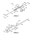
- FIG. 3 is an isometric view of a system for delivering prosthetic devices configured in accordance with various embodiments of the present technology.
- FIG. 4 is an isometric view of a distal portion of the system of FIG. 3 .
- FIG. 5 is an exploded isometric view of the distal portion of FIG. 4 in accordance with various embodiments of the present technology.
- FIG. 6 is a cross-sectional view of the distal portion taken along line 6 - 6 of FIG. 4 .
- FIG. 7 is a cross-sectional view of a control unit of the system of FIG. 3 .
- FIG. 8 is a detailed cross-sectional view of internal components of the control unit of FIG. 7 .
- FIG. 9 is a cross-sectional view of the control unit taken along line 9 - 9 of FIG. 7 .
- FIG. 10 is a cross-sectional view of a rotational control assembly in accordance with various embodiments of the present technology.
- FIGS. 11-14 are a series of views of a method of deploying a prosthetic device from a delivery capsule in accordance with various embodiments of the present technology.
- FIGS. 15-17 are a series of views of a method of deploying a prosthetic device from a delivery capsule in accordance with various embodiments of the present technology.
- FIG. 18 is an isometric view of a catheter for delivering a prosthetic device in accordance with various embodiments of the present technology.
- FIG. 19 is a side view of a control unit of the catheter of FIG. 18 in accordance with various embodiments of the present technology.
- FIG. 20 is a cross-sectional view of the control unit taken along line 20 - 20 of FIG. 19 .
- FIG. 21 is an exploded isometric view of a distal portion of the catheter of FIG. 18 .
- FIG. 22 is a cross-sectional view of the distal portion of the catheter of FIG. 18 .
- FIGS. 23-25 are a series of views of a method of deploying a prosthetic device from a delivery capsule of FIG. 22 in accordance with various embodiments of the present technology.
- FIGS. 26-29 are a series of views of a method of deploying a prosthetic device within a native mitral valve in accordance with various embodiments of the present technology.
- FIG. 30 is an isometric view of a distal portion of a catheter in accordance with various embodiments of the present technology.
- FIGS. 31 and 32 are isometric cutaway views of the distal portion of FIG. 30 .
- FIGS. 33-35 are a series of views of a method of deploying a prosthetic device from the catheter of FIG. 30 .
- FIG. 36 is a cross-sectional view of a distal portion of a catheter in accordance with various embodiments of the present technology.
- FIG. 37 is a cross-sectional view of the distal portion of FIG. 36 holding a prosthetic device in a partially expanded configuration.
- FIG. 38 is an isometric view of a positioner in accordance with various embodiments of the present technology.
- FIG. 39 is an exploded cross-sectional view of the distal portion of FIG. 36 in accordance with various embodiments of the present technology.
- FIG. 40 is an isometric view of a catheter for delivering a prosthetic device in accordance with various embodiments of the present technology.
- FIG. 41 is an isometric cutaway view of a control unit of the catheter of FIG. 40 in accordance with various embodiments of the present technology.
- FIG. 42 is a side view of a drive mechanism of the control unit of FIG. 41 .
- FIG. 43 is a detailed side view of a portion of the control unit of FIG. 41 .
- FIG. 44 is a schematic cross-sectional illustration of the heart and a catheter for transapically delivering a prosthetic device within a native mitral valve in accordance with various embodiments of the present technology.
- FIG. 45 shows a delivery capsule of the catheter of FIG. 44 aligned with the mitral valve.
- FIG. 46 is an isometric view of a distal portion of a catheter in accordance with various embodiments of the present technology.
- FIG. 47 is a top view of a positioning assembly in accordance with various embodiments of the present technology.
- FIG. 48 is a cross-sectional view of the positioning assembly taken along line 48 - 48 of FIG. 47 .
- FIGS. 49-53 are a series of views of a method of aligning a delivery capsule with a native mitral valve in accordance with various embodiments of the present technology.
- FIGS. 54-56 are a series of views of a method of aligning a delivery capsule with a native mitral valve in accordance with another embodiment of the present technology.
- FIG. 57 is a schematic cross-sectional illustration of the heart and a distal portion of a catheter positioned in a mitral valve in accordance with another embodiment of the present technology.
- FIG. 58 is a cross-sectional side view of the distal portion of FIG. 57 .
- FIG. 59 is an isometric view of a system for delivering a prosthetic device in accordance with various embodiments of the present technology.
- FIG. 60 is a cross-sectional view of a distal portion of the system taken along line 60 - 60 of FIG. 59 .
- FIGS. 61-65 are a series of views of a method of positioning the distal portion of FIG. 60 in accordance with various embodiments of the present technology.
- FIG. 66 is a cross-sectional side view of a distal portion of a catheter in accordance with various embodiments of the technology.
- FIG. 67 is a top view of a distal portion of a catheter positioned in a native mitral valve in accordance with various embodiments of the technology.
- FIG. 68 is a cross-sectional side view of the distal portion of FIG. 67 taken along line 68 - 68 .
- FIG. 69 shows a distal portion of a catheter in a guide catheter in accordance with various embodiments of the technology.
- FIG. 70 shows a delivery capsule that has been delivered out of the guide catheter of FIG. 69 .
- FIG. 71 is a schematic cross-sectional illustration of the heart and a distal portion of a catheter positioned in a mitral valve in accordance with another embodiment of the technology.
- FIG. 72 shows deployed positioners of the distal portion of FIG. 71 contacting the heart.
- FIGS. 73 and 74 are a series of views of a method of positioning a distal portion of a catheter using a transapical approach in accordance with various embodiments of the technology.
- FIG. 75 is a top view of a valve locator engaging a native mitral valve in accordance with various embodiments of the technology.
- FIG. 76 is a schematic cross-sectional illustration of the heart and the valve locator taken along line 76 - 76 of FIG. 75 .
- FIG. 77 is a top view of a kit for delivering devices into a patient in accordance with various embodiments of the technology.
- the present technology is generally directed to treatment of heart valves and other anatomical structures. Specific details of numerous embodiments of the technology are described below with reference to FIGS. 1-77 . Although many of the embodiments are described below with respect to catheter systems, prosthetic devices, and methods for treating a native heart valve using prosthetic devices, other applications and other embodiments in addition to those described herein are within the scope of the technology. A person of ordinary skill in the art will understand that the technology can have other embodiments with additional elements, or the technology can have other embodiments without several of the features shown and described below with reference to FIGS. 1-77 .
- distal and proximal within this description, unless otherwise specified, the terms can reference a relative position of the portions of a system, catheter, and/or associated delivery equipment with reference to an operator and/or a location in the patient.
- proximal can refer to a position closer to the operator of the catheter or an incision into vasculature
- distal can refer to a position that is more distant from the operator of the catheter or further from the incision along the vasculature (e.g., a position at an end of the catheter).
- the present technology is directed generally to systems, apparatuses, and methods to treat one or more sites in a subject's body.
- at least some embodiments of the present technology can be used to treat heart valves (e.g., mitral valves, aortic valves, tricuspid valves, and/or pulmonic valves).
- the treatment can include, without limitation, valve replacement, valve repair, valve alternation, or other procedures that affect functioning of the valve.
- the apparatuses and methods can enable a percutaneous approach using a catheter delivered intravascularly through a vein or an artery into the heart.
- the catheters and methods also enable other less-invasive approaches including, without limitation, trans-apical approaches, trans-atrial approaches, and direct aortic delivery. In more invasive approaches, the catheters and methods enable invasive approaches, including open procedures.
- a catheter includes a delivery device configured to contain a prosthetic device (e.g., a prosthetic heart valve device, a replacement heart valve, etc.).
- the delivery device can be a capsule reconfigured to deploy the prosthetic device.
- the delivery device can be moved from a containment configuration for holding the prosthetic device to a deployment configuration to deploy the prosthetic device.
- at least a portion of the capsule can be actuated (e.g., hydraulically actuated, mechanically actuated, etc.) to unsheathe or otherwise release at least a portion of the prosthetic device.
- the capsule can controllably deploy the prosthetic device to minimize, limit, or substantially eliminate uncontrolled movement of the prosthetic device.
- the capsule can limit, minimize, or substantially eliminate axial jumping, self-ejection, and/or movement of the prosthetic device that may cause misalignment with the native valve.
- the capsule e.g., a prosthetic mitral valve
- the prosthetic device in a delivery configuration can have an outer diameter of about 8 mm to about 12 mm for trans-apical approaches.
- the prosthetic device can also have a low profile suitable for delivery through small-diameter guide catheters positioned in the heart via the trans-septal, retrograde, or other approaches described herein.
- the prosthetic device in the delivery configuration can have an outer diameter equal to or less than about 10 mm for trans-septal approaches.
- the outer diameter of the trans-septal prosthetic device is about 8 mm to about 10 mm.
- the prosthetic device in the delivery configuration can have an outer diameter equal to about 8 mm to about 10 mm for retrograde approaches. Other dimensions are also possible.
- the prosthetic devices can be configured to expand to a deployed configuration.
- Delivery configuration generally refers to the prosthetic device once expanded at a delivery site (e.g., a native valve site) and subject to the constraining and distorting forces exerted by the native anatomy.
- expanded configuration generally refers to the configuration of a device when allowed to freely expand to an unrestrained size without the presence of constraining or distorting forces.
- the term “housing” generally refers to a structure capable of covering a prosthetic device.
- the housing can include multiple sheaths (e.g., a pair of sheathes).
- the housing can include a single sheath and a cover. The cover can be used to close and open an open end of the sheath.
- the housing can be a clam shell assembly that includes, without limitation, a pair of clam shells that can be moved apart to deploy the prosthetic device.
- the configuration and components of the housing can be selected based on, for example, the delivery path, treatment site, and/or configuration of the prosthetic device.
- the housing is part of a delivery capsule.
- a catheter for delivering a prosthetic device into a heart of a patient comprises a delivery capsule movable between different configurations (e.g., a containment configuration for holding the prosthetic device, a deployment configuration for deploying the prosthetic device, etc.) and a positioner (e.g., a percutaneous elongate positioner).
- the positioner is movable from a delivery state to a tissue-contacting state.
- the positioner in the tissue-contacting state is configured to contact tissue of the heart to position the prosthetic device contained in the delivery capsule relative to a native valve while the delivery capsule is reconfigured to deploy the prosthetic device within the native valve.
- a system may include a catheter with a control device.
- the control device can be configured to deploy the prosthetic device by hydraulically releasing at least a portion of the prosthetic device.
- a portion of the prosthetic device can be unsheathed mechanically and another portion of the prosthetic device can be unsheathed hydraulically. In other embodiments, however, the entire prosthetic device may be unsheathed hydraulically.
- the delivery capsule can be biased to counteract forces produced by the prosthetic device. In some embodiments, for example, a biasing force can counteract the forces produced by a self-expanding prosthetic device.
- control unit can be used to position the prosthetic device carried by the catheter to the treatment site.
- the control unit can include, without limitation, a screw-drive mechanism to controllable move at least a portion of housing to unsheathe a first portion of the prosthetic device. Another portion of the prosthetic device can be unsheathed before, during, and/or after unsheathing of the first portion of the prosthetic device.
- the control unit can include a slider mechanism used to axially move at least a portion of the housing to unsheathe the prosthetic device.
- the control unit may include other features and/or a different configuration.
- a system for implantation of a prosthetic heart valve device comprises an elongated catheter body and a delivery capsule coupled to the elongated catheter body.
- the delivery capsule is configured to contain a prosthetic heart valve device.
- the delivery capsule is configured to be hydraulically driven to deploy the prosthetic device (e.g., a prosthetic heart valve device).
- the delivery capsule can include a housing and a hydraulic mechanism (e.g., a piston device) that contacts the housing to inhibit movement of the delivery capsule from a containment configuration to a deployment configuration.
- the hydraulic mechanism can include one or more piston devices that contact the housing.
- the delivery capsule can include a biasing device that urges at least a portion of the delivery capsule towards a containment configuration when the delivery capsule moves from a containment configuration towards a deployment configuration.
- a system for delivering a prosthetic device includes an elongated catheter body, a housing, a plunger or piston, and a prosthetic device.
- the housing can be coupled to the elongated catheter body and can include a distal nose cone and a proximal capsule.
- the housing can include a split sheath.
- the prosthetic device and the plunger can be positioned in the housing to allow hydraulic actuation of the housing.
- the prosthetic device can be deployed in a controlled manner to minimize or limit jumping of the prosthetic device.
- FIGS. 1 and 1A show a heart H that comprises a right atrium RA and a right ventricle RV that receive blood from the body and pump the blood from the body to the lungs.
- the left atrium receives oxygenated blood from the lungs via the pulmonary veins PV and pumps this oxygenated blood through the mitral MV into the left ventricle LV.
- the left ventricle LV pumps the blood through the aortic valve AV into the aorta from which it flows throughout the body.
- the left ventricle LV of a normal heart H in systole is illustrated in FIG. 1A .
- the left ventricle LV contracts and blood flows outwardly through the aortic valve AV in the direction of the arrows.
- Back flow of blood or “regurgitation” through the mitral valve MV is prevented since the mitral valve is configured as a “check valve” which prevents back flow when pressure in the left ventricle is higher than that in the left atrium LA.
- the mitral valve MV comprises a pair of leaflets having free edges FE which meet evenly, or “coapt” to close, as illustrated in FIG. 1A .
- chordae tendineae CT which include a plurality of branching tendons secured over the lower surfaces of each of the valve leaflets LF.
- chordae CT in turn, are attached to the papillary muscles PM, which extend upwardly from the lower wall of the left ventricle and interventricular septum IVS.
- the mitral valve MV comprises a pair of leaflets having free edges FE which meet evenly, or “coapt” to close, as illustrated in FIG. 1A .
- the opposite ends of the leaflets LF are attached to the surrounding heart structure via an annular region of tissue referred to as an annulus AN.
- FIG. 1A-1 is a schematic cross-sectional side view of tissue of the mitral valve MV.
- the mitral valve MV includes the annulas AN and leaflets LF.
- Opposite ends of the leaflets LF are attached to the surrounding heart structure via a fibrous ring of dense connective tissue of the annulus AN, which is distinct from both the leaflet tissue LF as well as the adjoining muscular tissue of the heart wall.
- the leaflets LF and annulus AN are comprised of different types of cardiac tissue having varying strength, toughness, fibrosity, and flexibility. Tissue of the annular annulus AN is typically tougher, more fibrous, and stronger than leaflet tissue LF.
- the mitral valve MV may also comprise a unique region of tissue interconnecting each leaflet LF to the annulus AN, referred to herein as leaflet/annulus connecting tissue LAC (indicated by overlapping cross-hatching in FIG. 1A-1 ).
- a subannular surface of the mitral valve MV is a tissue surface lying on the ventricular side of the plane PO, and preferably one that faces generally downstream, toward the left ventricle LV.
- the subannular surface may be disposed on the annulus AN itself or the ventricular wall behind the native leaflets LF, or it may comprise a surface of the native leaflets LF, either inward-facing IF or outward-facing OF, which lies below the plane PO.
- the subannular surface or subannular tissue may thus comprise the annulus AN itself, the native leaflets LF, leaflet/annulus connective tissue, the ventricular wall or combinations thereof.
- FIGS. 1B to 1D show a number of structural defects in the heart can cause mitral valve regurgitation.
- Ruptured chordae RCT as shown in FIG. 1B , can cause a valve leaflet LF 2 to prolapse since inadequate tension is transmitted to the leaflet via the chordae. While the other leaflet LF 1 maintains a normal profile, the two valve leaflets do not properly meet and leakage from the left ventricle LV into the left atrium LA will occur, as shown by the arrow.
- Regurgitation also occurs in patients suffering from cardiomyopathy where the heart is dilated and the increased size prevents the valve leaflets LF from meeting properly, as shown in FIG. 1C .
- the enlargement of the heart causes the mitral annulus to become enlarged, making it impossible for the free edges FE to meet during systole.
- the free edges of the anterior and posterior leaflets normally meet along a line of coaptation C as shown in FIG. 1C-1 , but a significant gap G can be left in patients suffering from cardiomyopathy, as shown in FIG. 1C-2 .
- FIG. 1D shows an impaired mitral valve. Mitral valve regurgitation can also occur in patients who have suffered ischemic heart disease where the functioning of the papillary muscles PM is impaired. As the left ventricle LV contracts during systole, the papillary muscles PM do not contract sufficiently to effect proper closure. One or both of the leaflets LF 1 and LF 2 then prolapse, as illustrated. Leakage again occurs from the left ventricle LV to the left atrium LA, as shown by the arrow.
- FIGS. 1C-1, 1C-2, and 1E illustrate the shape and relative sizes of the leaflets L of the mitral valve. It may be seen that the overall valve has a generally kidney-like shape, with a long axis MVA 1 and a short axis MVA 2 .
- the long axis MVA 1 is typically within a range from about 33.3 mm to about 42.5 mm in length (37.9+/ ⁇ 4.6 mm)
- the short axis MVA 2 is within a range from about 26.9 mm to about 38.1 mm in length (32.5+/ ⁇ 5.6 mm).
- MVA 1 can be within a range from about 45 mm to 55 mm and MVA 2 can be within a range from about 35 mm to about 40 mm.
- the line of coaptation C is curved or C-shaped, thereby defining a relatively large anterior leaflet AL and substantially smaller posterior leaflet PL ( FIG. 1C-1 ). Both leaflets can be generally crescent-shaped from the superior or atrial side, with the anterior leaflet AL being substantially wider in the middle of the valve than the posterior leaflet. At the opposing ends of the line of coaptation C the leaflets join together at corners called the anterolateral commissure AC and posteromedial commissure PC, respectively.
- FIG. 1E shows the shape and dimensions of the annulus AN.
- the annulus AN is an annular area around the circumference of the valve and may comprise a saddle-like shape with a first peak portion PP 1 and a second peak portion PP 2 located along an interpeak axis IPD, and a first valley portion VP 1 and a second valley portion VP 2 located along an intervalley axis IVD.
- the first and second peak portions PP 1 and PP 2 are higher in elevation relative to a plane containing the nadirs of the two valley portions VP 1 , VP 2 , typically being about 8 mm to about 19 mm higher in humans, thus giving the valve an overall saddle-like shape.
- interpeak span IPD The distance between the first and second peak portions PP 1 , PP 2 , referred to as interpeak span IPD, is substantially shorter than the intervalley span IVD, the distance between first and second valley portions VP 1 , VP 2 .
- the dimensions and physiology of the patient may vary among patients, and although some patients may comprise differing physiology, the teachings as described herein can be adapted for use by many patients having various conditions, dimensions and shapes of anatomical structures. For example, some patients may have a long dimension across the annulus and a short dimension across the annulus of the mitral valve without well defined peak and valley portions, and the methods and apparatus as described herein can be configured accordingly.
- Access to treatment sites can be provided by various techniques and procedures.
- minimally invasive surgery techniques can provide access to treatment sites in the heart.
- minimally invasive surgery techniques may be percutaneous procedures in which access can be accomplished through the patient's vasculature.
- Percutaneous procedures refer to procedures in which a location of the vasculature remote from the heart is accessed through the skin, often using a surgical cut down procedure or a minimally invasive procedure, such as using needle access through, for example, the Seldinger technique.
- the ability to percutaneously access remote vasculature is well-known and described in patent literature and medical literature.
- the approach to a mitral valve may be antegrade and may rely on entry into the left atrium by crossing the interatrial septum.
- the approach to the mitral valve can be retrograde where the left ventricle is entered through the aortic valve.
- a catheter 10 having a needle 12 may be advanced from the inferior vena cava IVC into the right atrium RA. Once the catheter 10 reaches the anterior side of the interatrial septum IAS, the needle 12 may be advanced so that it penetrates through the septum, for example at the fossa ovalis FO or the foramen ovale into the left atrium LA. At this point, a guidewire may be exchanged for the needle 12 and the catheter 10 withdrawn.
- access through the interatrial septum may usually be maintained by the placement of a guide catheter 14 (e.g., a steerable catheter, a guide sheath, etc.), typically over a guidewire 16 which has been placed as described above.
- the guide catheter 14 affords subsequent access to permit introduction of a catheter to treat the mitral valve, as described in more detail herein below.
- the antegrade or transseptal approach to the mitral valve can be advantageous in many respects.
- the use of the antegrade approach may allow for more precise and effective centering and stabilization of the guide catheter and/or prosthetic device (e.g., a prosthetic heart valve). Precise positioning facilitates accuracy in the placement of the prosthetic valve apparatus.
- the antegrade approach may also reduce the risk of damaging the subvalvular apparatus during catheter and interventional tool introduction and manipulation. Additionally, the antegrade approach may decrease risks associated with crossing the aortic valve as in retrograde approaches. This can be particularly relevant to patients with prosthetic aortic valves, which cannot be crossed at all or without substantial risk of damage.
- FIGS. 1H and 1I An example of a retrograde approach to the mitral valve is illustrated in FIGS. 1H and 1I .
- the mitral valve MV may be accessed by an approach from the aortic arch AA, across the aortic valve AV, and into the left ventricle below the mitral valve MV.
- the aortic arch AA may be accessed through a conventional femoral artery access route, as well as through more direct approaches via the brachial artery, axillary artery, or a radial or carotid artery. Such access may be achieved with the use of a guidewire 16 .
- a guide catheter 14 may be tracked over the guidewire 16 ( FIG. 1H ).
- the guide catheter 14 affords subsequent access to permit placement of the prosthetic device, as described in more detail below.
- a retrograde arterial approach to the mitral valve can be preferred due to its advantages.
- Use of the retrograde approach can eliminate the need for a trans-septal puncture.
- the retrograde approach is also commonly used by cardiologists and thus has the advantage of familiarity.
- FIG. 1J An additional approach to the mitral valve is via trans-apical puncture, as shown in FIG. 1J .
- access to the heart can be gained via thoracic incision, which can be a conventional open thoracotomy or sternotomy, or a smaller intercostal or sub-xyphoid incision or puncture.
- An access device e.g., a cannula, a guide catheter, etc.
- a puncture sealed by a purse-string suture, in the wall of the left ventricle near the apex of the heart.
- the catheters and prosthetic devices disclosed herein may then be introduced into the left ventricle through this access cannula.
- the trans-apical approach can have the advantage of providing a shorter, straighter, and more direct path to the mitral valve or aortic valve. Further, because it does not involve intravascular access, it can be performed by surgeons who may not have the necessary training in interventional cardiology to perform the catheterizations of other percutaneous approaches.
- the interventional tools and catheters may be advanced to the heart intravascularly and positioned adjacent the target cardiac valve in a variety of manners.
- access to a delivery site can be through the chest of the patient and may be provided by, for example, conventional transthoracic surgical approaches, open and semi-open heart procedures, laparoscopic techniques, and port access techniques.
- Such surgical access and procedures can utilize conventional surgical instruments, including, for example, retractors, rib spreaders, trocars, laparoscopic instruments, forceps, scissors, shears, rongeurs, fixation devices (e.g., clip appliers, clamps, etc.), staplers, sutures, needle holders, cauterizing instruments, electrosurgical pens, suction apparatuses, approximators, and/or the like.
- conventional surgical instruments including, for example, retractors, rib spreaders, trocars, laparoscopic instruments, forceps, scissors, shears, rongeurs, fixation devices (e.g., clip appliers, clamps, etc.), staplers, sutures, needle holders, cauterizing instruments, electrosurgical pens, suction apparatuses, approximators, and/or the like.
- At least some catheters disclosed herein can deploy prosthetic devices as an adjunct to a surgical heart procedure (e.g., coronary artery bypass surgery, replacing and/or repairing portions of the heart, etc), such that one or more prosthetic devices can be delivered without performing additional complicated procedures for gaining access to the treatment site.
- a heart valve repair procedure e.g., aortic valve repair, mitral valve repair, pulmonary valve repair, etc.
- valve replacement may be performed on another heart valve (e.g., a diseased aortic valve, a mitral valve, a pulmonary valve, etc.).
- an intravascular catheter can be flexible, while a transapical catheter can be generally rigid.
- the properties, dimensions (e.g., width, length, etc.), and configuration of the catheter can be selected based on the delivery approach.
- the catheter can include one or more lumens for aspirating fluid (e.g., air, blood, etc.) from a delivery capsule.
- the lumens can be used to de-air the catheter prior to introduction to the patient's body.
- a wide range of surgical instruments can be used to access the heart, perform surgical procedures on the heart, and assist in operation of a catheter capable of delivering a prosthetic device in the heart.
- Such surgical instruments include, without limitation, sizing rings, balloons, calipers, gages, and other surgical tools can be selected based on, for example, desired access path, dimensions and configuration of the delivery apparatuses, and an anatomical structure of the heart.
- Orientation and steering of the treatment apparatuses e.g., catheters
- Such orientation may be accomplished by gross steering of the treatment apparatus to the desired location and then refined steering of the components of the treatment apparatus to achieve a desired result.
- a steerable guidewire may be used to introduce a guide catheter and a catheter for delivering a prosthetic device into the proper position.
- the guide catheter may be introduced, for example, using a surgical cut down or Seldinger access to the femoral artery in the patient's groin. After placing a guidewire, the guide catheter may be introduced over the guidewire to the desired position.
- a shorter and differently shaped guide catheter could be introduced through the other routes described above.
- a guide catheter may be pre-shaped to provide a desired orientation relative to the treatment site.
- the guide catheter may have a curved shape, an angled configuration, or other suitable shape at its tip to orient the distal end toward the mitral valve from the location of the septal puncture through which the guide catheter extends.
- guide catheter 14 may have a pre-shaped J-tip which is configured so that it turns toward the mitral valve MV after it is placed over the aortic arch AA and through the aortic valve AV. As shown in FIG.
- the guide catheter 14 may be configured to extend down into the left ventricle LV and to evert so that the orientation of an interventional tool or catheter is more closely aligned with the axis of the mitral valve MV.
- a pre-shaped guide catheter may be configured to be straightened for endovascular delivery by means of a stylet or stiff guidewire which is passed through a lumen of the guide catheter.
- the guide catheter might also have pull-wires or other features to adjust its shape for more fine steering adjustment.
- FIG. 2A is a schematic cross-sectional illustration of a heart and a delivery capsule of a catheter delivered via a trans-apical approach to the mitral valve.
- FIG. 2B shows the delivery capsule in a deployment configuration and a deployed prosthetic device.
- a system 100 can include a guide catheter 110 and a catheter 102 extending through the guide catheter 110 .
- the guide catheter 110 is positioned in a trans-apical opening 114 to provide access to the left ventricle LV.
- the catheter 102 can include a hydraulically actuatable delivery capsule 122 (“delivery capsule 122 ”) and an elongated catheter body 124 (“catheter body 124 ”).
- the delivery capsule 122 may be positioned between a posterior leaflet 130 and an anterior leaflet 134 of a mitral valve 140 .
- the catheter body 124 can be conveniently moved in the superior direction (as indicated by arrow 166 ) and the inferior direction (as indicated by arrow 168 ) to position the delivery capsule 122 at a desired location within an opening 160 of the mitral valve 140 .
- the delivery capsule 122 can be hydraulically driven from a containment configuration ( FIG. 2A ) towards a deployment configuration ( FIG. 2B ) to deploy a prosthetic device 150 , such as a prosthetic heart valve (the prosthetic device 150 is shown schematically in dashed lines).
- the delivery capsule 122 is expected to reduce, limit, or substantially eliminate uncontrolled movement of the prosthetic device 150 caused by forces associated with expansion of the prosthetic device 150 .
- Such uncontrolled movement can include, for example, axial jumping, self-ejection, or other types of uncontrolled movement.
- the delivery capsule 122 is expected to inhibit or prevent translation of the prosthetic device 150 while at least a portion of the prosthetic device 150 expands to contact the treatment site.
- a biasing force provided by a biasing device can limit or substantially prevent opening of the delivery capsule 122 attributable to the forces produced by the prosthetic device 150 .
- an unsheathed portion of the prosthetic device 150 can expand outwardly from the partially opened delivery capsule 122 while the biasing device inhibits further opening of the delivery capsule 122 .
- the delivery capsule 122 can be hydraulically driven towards the deployment configuration in a controlled manner to deploy the prosthetic device 150 at the treatment site. Further details regarding the delivery capsule 122 are provided below.
- the prosthetic device 150 is in a deployed configuration.
- the opened delivery capsule 122 can now be moved back to the containment configuration and moved proximally through the deployed prosthetic device 150 .
- the catheter 102 can be pulled proximally through the guide catheter 110 and removed from the patient. The catheter 102 can then be used to deliver additional prosthetic devices or it can be discarded.
- FIG. 3 is an isometric view of the system 100 including the catheter 102 , a guidewire 208 , and a fluid system 206 .
- the fluid system 206 is configured to deliver fluid to the catheter 102 to hydraulically operate the delivery capsule 122 .
- the catheter 102 can include a handheld control unit 210 (“control unit 210 ”) configured to provide steering capability (e.g., 360 degree rotation of the delivery capsule 122 , 180 degree rotation of the delivery capsule 122 , 3-axis steering, 2-axis steering, etc.).
- the control unit 210 can include a rotational control assembly 214 (“control assembly 214 ”) and a steering mechanism 216 .
- a knob 224 of the control assembly 214 can be rotated to rotate the delivery capsule 122 about its longitudinal axis 230 .
- a knob assembly 240 of the steering mechanism 216 can be used to steer the catheter 102 by bending a distal portion thereof about a transverse axis.
- the control unit 210 may include different features and/or have a different arrangement.
- the fluid system 206 can include a fluid source 250 and a line 251 coupling the fluid source 250 to the catheter 102 .
- the fluid source 250 may contain a flowable substance (e.g., water, saline, etc.) and can include, without limitation, one or more pressurization devices, fluid connectors, fittings, valves, or other fluidic components.
- the pressurization devices can include a pump (e.g., a positive displacement pump, a plunger pump, etc.), a syringe pump (e.g., a manually operated syringe pump), or other devices capable of pressurizing the flowable substance.
- the line 251 can include, without limitation, one or more hoses, tubes, or other components (e.g., connectors, valves, etc.) through which the flowable substance can pass.
- the fluid source 250 may comprise a controller 252 including, without limitation, one or more computers, central processing units, processing devices, microprocessors, digital signal processors (DSPs), and/or application-specific integrated circuits (ASICs).
- the controller 252 can include, without limitation, one or more storage elements, such as volatile memory, non-volatile memory, read-only memory (ROM), and/or random access memory (RAM).
- the stored information can include, pumping programs, patient information, and/or executable programs.
- the controller 252 can further include a manual input device (e.g., a keyboard, a touch screen, etc.) or an automated input device (e.g., a computer, a data storage device, servers, network, etc.).
- the controller 252 may include different features and/or have a different arrangement.
- FIG. 3 shows the catheter 102 traveling over the guidewire 208 .
- the guidewire 208 includes a proximal portion 260 , a distal portion 262 , and a main body 264 .
- the proximal portion 260 extends proximally from the control assembly 214
- the distal portion 262 extends distally past the delivery capsule 122 .
- the guidewire 208 can be used to guide the delivery capsule 122 into the native heart valve.
- FIG. 4 is an isometric view of a distal portion of the catheter 102 configured in accordance with various embodiments of the present technology.
- the delivery capsule 122 can include a housing 268 configured to hold the prosthetic device 150 (shown schematically in broken lines).
- the housing 268 can include a distal sheath 270 and a proximal sheath 272 .
- the distal sheath 270 can include a closed distal end 274 and a distal containment portion 275 .
- the distal end 274 can have a guidewire-receiving opening 276 and can have an atraumatic configuration (e.g., a substantially partially spherical shape, blunt configuration, rounded configuration, etc.) to limit or prevent injury or trauma to tissue.
- the distal containment portion 275 can contain a distal portion of the prosthetic device 150 .
- the proximal sheath 272 can include a proximal containment portion 284 , a tapered portion 287 , and a guide portion 290 .
- the proximal containment portion 284 can contain a proximal portion of the prosthetic device 150 and can mate with the distal containment portion 275 .
- the tapered portion 287 can have a frusto-conical shape, a partially spherical shape, or other suitable configuration for substantially preventing or limiting injury or trauma to tissue when the delivery capsule 122 is pulled proximally through the subject.
- the guide portion 290 can closely surround the catheter body 124 .
- the distal sheath 270 and/or proximal sheath 272 can be made, in whole or in part, of metal, polymers, plastic, composites, combinations thereof, or other materials capable of holding the prosthetic device 150 .
- the distal containment portion 275 can be a tubular member (e.g., a tubular portion with a generally circular cross section, a generally elliptical cross section, etc.) made of metal or other rigid materials.
- the distal sheath 270 or proximal sheath 272 can be configured to contain the entire valve prosthetic device 150 .
- FIG. 5 is an exploded isometric view of the distal portion of the catheter 102 .
- the delivery capsule 122 can include a piston device 292 and a biasing device 294 .
- the piston device 292 can include a distal head assembly 300 , a proximal head assembly 304 , and a connector 310 .
- the connector 310 can include ends 330 , 350 connected to the distal and proximal head assemblies 300 , 304 , respectively.
- the distal head assembly 300 can include a head 320 and a sealing member 322 .
- the head 320 can include a through-hole 331 and a channel 332 for receiving the sealing member 322 .
- the proximal head assembly 304 can include a head 340 and a sealing member 342 .
- the head 340 can include a channel 352 for receiving the sealing member 342 and a holder 360 .
- the holder 360 is configured to retain the prosthetic device 150 and can include a hub 362 and retaining features in the form of posts 364 a , 364 b , 364 c (collectively “posts 364 ”).
- the posts 364 are circumferentially spaced apart about the hub 362 .
- the three posts 364 extend radially outward. In other embodiments, however, the number of posts 364 can be increased or decreased and the posts 364 may be arranged evenly or unevenly about the hub 362 .
- the posts 364 can pass through receiving features (e.g., openings, holes, eyelets, etc.) of the prosthetic device 150 to inhibit, prevent, or substantially eliminate movement of the prosthetic device 150 along the longitudinal axis 230 of the delivery capsule 122 .
- receiving features e.g., openings, holes, eyelets, etc.
- prosthetic device 150 When being deployed, prosthetic device 150 can radially expand along the posts 364 to move towards a deployed configuration (e.g., an expanded configuration). For example, in some embodiments the prosthetic device 150 can move past the ends of the posts 364 to disengage the delivery capsule 122 under its own spring load. In other embodiments, the posts 364 can be moved inwardly into the hub 362 to release the prosthetic device 150 .
- the holder 360 can also include one or more retaining features in the form of hooks, clamps, or other types of features capable of holding and releasing a prosthetic device. In other embodiments, the posts 364 may have a different arrangement relative to the prosthetic device 150 .
- the sealing members 322 and 342 are positioned to engage the distal and proximal sheaths 270 and 272 , respectively, and can be made, in whole or in part, of silicon, rubber, polymers, elastomers, combinations thereof, or other compliant materials suitable for forming seals.
- one or both sealing members 322 , 342 are gaskets or O-rings made, in whole or in part, of rubber.
- the sealing members 322 , 342 can be bladder seals. Other types of sealing members 322 , 342 can be used, if needed or desired.
- FIG. 5 shows the biasing device 294 carried by the catheter body 124 .
- the term “biasing device” refers generally to one or more biasing members, such as linear springs, non-linear springs, or other devices capable of providing a biasing force.
- the biasing device 294 may comprise a linear spring for deploying a prosthetic device 150 that produces a substantially constant deployment forces.
- the biasing device 294 may comprise a non-linear spring for deploying a prosthetic device 150 that produces varying deployment forces.
- the biasing device 294 can be made of metal, polymers, or combinations thereof.
- the biasing device 294 can be made, in whole or in part, of steel (e.g., spring steel), nickel titanium (e.g., nitinol), or other alloys.
- the biasing device 294 is a helical spring made of nitinol.
- the biasing device 294 is a metal hypotube that has been cut (e.g., laser cut) in a spiral pattern.
- the biasing device 294 can have a proximal end 372 , a distal end 374 , and a main body 376 .
- the proximal end 372 can be adjacent a shoulder 380 of the catheter body 124 .
- the catheter body 124 can include a narrowed portion 381 extending through the biasing device 294 and a widened portion 383 .
- the widened portion 383 defines the shoulder 380 .
- the catheter body 124 can be made, in whole or in part, of plastic, thermoplastic elastomers (e.g., resins such as Pebax®), or other flexible materials.
- the catheter body 124 can be generally rigid for delivery using, for example, a transapical approach.
- FIG. 6 is a partially schematic cross-sectional view of the distal position of the catheter 102 configured in accordance with various embodiments of the present technology.
- the distal sheath 270 , the proximal sheath 272 , and the head assemblies 300 , 304 cooperate to define a containment or main chamber 400 .
- the containment chamber 400 is configured to contain the prosthetic device 150 . Equal parts of the containment chamber 400 may be disposed in the distal sheath 270 and proximal sheath 272 , or the containment chamber 400 may have a larger portion or even its entirety contained in either the distal or proximal sheath.
- the sealing member 322 is positioned to sealingly engage the distal sheath 270 to form a fluid chamber 410 (e.g., a fluidically sealed chamber or an isolated fluid chamber).
- the sealing member 342 is positioned to sealingly engage the proximal sheath 272 to form a fluid chamber 412 .
- the fluid chambers 410 , 412 can be fluidically sealed from the containment chamber 400 .
- a flowable substance can be delivered into the fluid chamber 410 to move the distal sheath 270 in the distal direction (indicated by arrow 416 ) to unsheathe an upstream or atrial portion 424 of the prosthetic device 150 .
- Fluid can be delivered into the fluid chamber 412 to move the proximal sheath 272 in the proximal direction (indicated by arrow 418 ) to unsheathe a downstream or ventricular end or portion 426 of the prosthetic device 150 .
- the distal end 274 of the distal sheath 270 can include a wall 440 and a passageway 444 .
- a rod 450 can be positioned in at least a portion of the passageway 444 .
- the rod 450 can include, for example, a distal end 451 coupled to the distal sheath 270 and a retaining head 530 positioned in a lumen 454 of the piston device 294 .
- the rod 450 can be hollow to receive a guidewire.
- the distal containment portion 275 includes a proximal open end 432 and a cylindrical sidewall 460 .
- the cylindrical sidewall 460 can include an inner surface 462 and an outer surface 464 .
- the sealing member 322 can physically contact the inner surface 462 to form a seal (e.g., an airtight seal, a fluid-tight seal, etc.).
- the proximal containment portion 284 of the proximal sheath 272 can include a distal open end 470 and a closed proximal end 472 .
- the distal open end 470 is received by the proximal open end 432 of the distal sheath 270 .
- a seal may be formed by the distal open end 470 and the proximal open end 432 .
- the guide portion 290 of the proximal sheath 272 has a sidewall 488 that defines a lumen 490 .
- the proximal sheath 272 can further include a stop 496 extending inwardly into the lumen 490 . When the proximal sheath 272 is moved proximally (as indicated by arrow 418 ), the stop 496 can contact the biasing device 294 .
- the narrowed portion 381 of the catheter body 124 extends through the biasing device 294 and can include one or more ports 500 (one port 500 is identified in FIG. 6 ). Fluid can flow along a fluid lumen 388 , through the port(s) 500 , and into the fluid chamber 412 . The number, sizes, and positions of the ports 500 can be selected to achieve the desired flow of fluid into the fluid chamber 412 . A seal between the stop 496 and the narrowed portion 381 and/or a seal 509 between the guide portion 290 and the widened portion 383 can help achieve the desired fluid pressure in the chamber 412 .
- the catheter body 124 can include multiple lumens.
- One fluid lumen for example, can provide fluid communication with fluid chamber 410
- another fluid lumen can provide fluid communication with the fluid chamber 412 .
- Fluid can be independently delivered into and removed from the respective fluid chambers 410 , 412 .
- fluid at a first pressure can be delivered into the fluid chamber 410 to move the distal sheath 270 .
- fluid at a second pressure can be delivered into the fluid chamber 412 to move the proximal sheath 272 .
- the second pressure can be equal to or different from the first pressure.
- FIG. 7 is a partially schematic cross-sectional view of the control unit 210 of FIG. 3 .
- the control unit 210 can further include an articulation mechanism 218 .
- the articulation mechanism 218 includes a slider assembly 519 and a coupler 520 .
- the slider assembly 519 can include a rod 518 and a knob 521 .
- the rod 518 can have external threads that threadably engage internal threads of a threaded retainer 527 .
- a pull wire 523 can couple the coupler 520 to the catheter body 124 such that rotation of the knob 521 about an axis of rotation 525 causes axial movement of the rod 518 .
- the rod 518 can be moved distally or proximally to decrease or increase, respectively, the tension in the pull wire 523 to articulate the catheter 102 .
- the pull wire 523 can be tensioned to, for example, bend the catheter body 124 up or down.
- the pull wire 523 can be tensioned to bend or articulate the catheter body 124 in other directions.
- a tubular member 531 can be coupled to the catheter body 124 and the knob 224 ( FIG. 3 ).
- a locking feature 529 e.g. a screw, a fastener, or the like
- the locking feature 529 can be in a locked position to securely hold the tubular member 531 to prevent rotation of the catheter body 124 .
- the locking feature 529 can be moved to an unlocked position to allow rotation of the tubular member 531 and the catheter body 124 .
- the locking feature 529 can have a different arrangement and/or different features.
- FIG. 8 is a detailed cross-sectional view of a connector assembly 533 configured for use with the control unit of FIG. 7 .
- the connector assembly 533 can include a junction 534 and a swiveling member 538 .
- the junction 534 is configured to fluidically couple the line 251 to the catheter body 124 .
- the line 251 is coupled to an inlet 537 of the junction 534 .
- the swiveling member 538 can rotatably couples the catheter body 124 to a housing 517 .
- FIG. 9 is a cross-sectional view of the control unit 210 with knob assemblies 240 a , 240 b (collectively “knob assemblies 240 ”) taken along line 9 - 9 of FIG. 7 .
- the knob assemblies 240 can be operated to move the delivery capsule 122 .
- the knob assembly 240 a can be rotated to move the delivery capsule 122 to the right
- the knob assembly 240 b can be rotated to move the delivery capsule 122 to the left.
- the knob assemblies 240 can be used to bend the catheter body 124 to the left or right, while the articulation mechanism 218 can be used to move bend the catheter body 124 up or down.
- the knob assemblies 240 can be generally similar to each other and, accordingly, the description of one knob assembly applies equal to the other knob assembly, unless indicated otherwise.
- the knob assemblies 240 may include different features and/or have a different arrangement to, for example, controllably move the catheter body 124 in opposite directions.
- the knob assemblies 240 a , 240 b may be coupled to the catheter body 124 via pull wires 542 a , 542 b , respectively.
- the knob assembly 240 a includes a knob 543 a coupled to a pulley 545 a .
- the wire 542 a is wrapped around the pulley 545 a such that rotation of the knob 543 a can increase or decrease the length of the pull wire 542 a extending from the pulley 545 a .
- the knob 543 a can be rotated to wrap the wire 542 a around the pulley 545 a to increase the tension in the wire 542 a .
- the knob 543 a can be rotated in the opposite direction to unwind the wire 542 a from the pulley 545 a to decrease the tension in the wire 542 a .
- the control unit 210 can further include a stress-relief feature 516 coupled to the housing 517 .
- the stress-relief feature 516 may be configured to surround the catheter body 124 and can be made of a flexible material. In other embodiments, however, the control unit 210 may not include the stress-relief feature 516 or the stress-relief feature 516 may include different features.
- FIG. 10 is a cross-sectional view of the control assembly 214 of FIG. 3 .
- the control assembly 214 can include a sealing assembly 548 and the knob 224 .
- the knob 224 can be fixedly coupled to the tubular member 531 .
- the knob 224 for example, can be rotated about an axis of rotation 546 to cause corresponding rotation of the tubular member 531 .
- the control assembly 214 may include different features and/or have different features.
- FIGS. 11-14 are a series of views of a method of deploying the prosthetic device 150 .
- the delivery capsule 122 is configured to be positioned within the patient's mitral valve 140 .
- the distal sheath 270 can be hydraulically driven to unsheathe the atrial end 424 of the prosthetic device 150 .
- the unsheathed atrial end 424 can move outwardly to engage the tissue of the mitral valve 140 while the delivery capsule 122 holds the ventricular end 426 of the prosthetic device 150 .
- the proximal sheath 272 can be hydraulically driven to unsheathe the ventricular end 426 of the prosthetic device 150 .
- the unsheathed ventricular end 426 can move outwardly to engage the tissue of the mitral valve 140 .
- FIG. 11 shows an opening 510 formed at the apex 512 of the heart H to access the left ventricle LV.
- the opening 510 can be an incision formed by, for example, a needle, a cutting tool, or a catheter (e.g., a needle catheter).
- the guide catheter 110 can be moved distally through the opening 510 and into the left ventricle LV.
- the guidewire 208 can be moved through the guide catheter 110 and positioned between the posterior and anterior leaflets 130 , 134 .
- the distal portion 262 of the guidewire 208 can be moved into the left atrium LA.
- the distal portion 262 can be an atraumatic tip (e.g., a flexible tip, a curved tip, a rounded tip, etc.) to prevent, inhibit, or substantially prevent injury to the heart tissue.
- the delivery capsule 122 is ready to be moved between the posterior and anterior leaflets 130 , 134 .
- the delivery capsule 122 can be advanced over the guidewire 208 while the mitral valve 140 opens and closes.
- the mitral valve 140 is closed (as shown in FIG. 11 )
- the posterior and anterior leaflets 130 , 134 can seal around the guidewire 208 .
- the guidewire 208 can be conveniently advanced through the mitral valve 140 .
- FIG. 12 shows the delivery capsule 122 positioned between the posterior and anterior leaflets 130 , 134 .
- a position indicator (e.g., in the form of a marker 501 ) may be carried on the proximal sheath 272 .
- the delivery capsule 122 can be rotated about its longitudinal axis 230 to align the marker 501 with the mitral valve 140 .
- Markers can be located on an exterior surface of the distal sheath 270 , on an exterior surface of the proximal sheath 272 , within internal components of the delivery capsule 122 , or at other suitable locations.
- markers can be resonant markers for MR imaging-guided delivery.
- markers can be echocardiographic markers viewable under echocardiography.
- a posterior side of the prosthetic device 150 can be aligned with the posterior leaflet 130 using a marker on a posterior side of the delivery capsule 122 . Additionally or alternatively, a marker on an anterior side of the delivery capsule 122 can be used to align the anterior side of the delivery capsule 122 with the anterior leaflet 134 .
- FIG. 12 further illustrates the prosthetic device 150 ready to be deployed.
- the fluid system 206 ( FIG. 3 ) is configured to deliver fluid into the catheter 102 , and the fluid can flow distally along the fluid lumens 388 , 524 and into the chamber 410 .
- the fluid fills the chamber 410 and causes movement of the distal sheath 270 in the distal direction. Friction, if any, between the prosthetic device 150 and the distal sheath 270 may cause pulling on the prosthetic device 150 .
- the delivery capsule 122 is configured to hold the prosthetic device 150 to prevent, for example, inadvertent distal movement of the prosthetic device 150 .
- the distal sheath 270 can be advanced distally until the head 530 contacts stops 532 .
- FIG. 13 shows the distal sheath 270 after it has been moved to an open or deployed position.
- the unsheathed atrial end 424 of the prosthetic device 150 has moved (as indicated by arrows) through an opening 540 to allow the atrial end 424 to radially expand.
- An atrial rim 427 of the atrial end 424 can expand to its fully deployed configuration (shown) to engage native heart tissue around the circumference (e.g., most of or the entire circumference) of the mitral valve 140 .
- the atrial rim 427 can contact the native annulus AN, tissue proximate to the native annulus AN either in the atrium or ventricle, the native valve leaflets, and/or other tissue suitable for contacting the prosthetic device 150 .
- the atrial rim 427 can contact the leaflet/annulus connecting tissue and tissue of the leaflets proximate to the native annulus AN.
- the radially unrestrained atrial end 424 expands upon unsheathing.
- expanders can be used to expand the unsheathed atrial end 424 .
- an expander in the form of a balloon can be positioned within the prosthetic device 150 and can be inflated to deploy the atrial end 424 .
- the delivery capsule 122 is expected to substantially prevent axial movement of the prosthetic device 150 .
- the holder 360 can prevent translation of the sheathed portion of the prosthetic device 150 while the atrial end 424 expands.
- the expanded portion of the prosthetic device 150 may pull on the sheathed portion of the prosthetic device 150 .
- the prosthetic device 150 would deploy in an uncontrolled manner but for the holder 360 restraining axial translation of the prosthetic device 150 .
- the holder 360 can hold the proximal sheath 272 substantially stationary relative to the mitral valve 140 . As shown in FIGS. 12 and 13 , the axial position of the prosthetic device 150 can be maintained throughout expansion of the atrial end 424 .
- the force exerted by the biasing device 294 can be sufficient to prevent uncontrolled movement of the proximal sheath 272 in the proximal direction.
- the partially expanded prosthetic device 150 of FIG. 13 may contact and apply a force component (e.g., an axially directed force component, a proximally-directed force component, etc.) to the distal end 470 of the proximal sheath 272 .
- the compressed biasing device 294 can urge the proximal sheath 272 in the distal direction to counteract the force component.
- the biasing device 294 can thus inhibit, limit, or substantially prevent movement of the proximal sheath 272 in the proximal direction caused by the prosthetic device 150 .
- the characteristics (e.g., spring constant, applied force versus deflection curve, etc.) of the biasing device 294 can be selected based on the forces that will be produced by the prosthetic device 150 .
- Linear springs can be used with, for example, prosthetic devices that produce substantially constant deployment forces (e.g., substantially constant proximally-directed force component).
- Non-linear springs can be used with, for example, prosthetic devices that produce varying deployment forces.
- the biasing device 294 can provide a variable force.
- the variable force can be generally maximum when the forces from the prosthetic device 150 pushing on the delivery capsule 122 are highest and resistance between the delivery capsule and the prosthetic device is lowest.
- the prosthetic device 150 is unsheathed from the delivery capsule 122 , a greater and greater portion of the prosthetic device is exposed outside the delivery capsule and the forces exerted by the exposed portion of the prosthetic device urging the delivery capsule to the open configuration are increasing.
- the surface area of the prosthetic device 150 remaining in the delivery capsule 122 is decreasing, thus reducing the frictional resistance between the prosthetic device 150 and the delivery capsule 122 .
- biasing device 294 can be a spring which applies a force that increases with spring displacement.
- the biasing device 294 can include plurality of springs. For example, one spring can have a low spring constant to counteract low forces applied by the prosthetic device 150 to the delivery capsule 122 . Another spring can have a relative large spring constant to counteract high forces applied by the prosthetic device 150 to the delivery capsule 122 .
- the biasing device 294 can be offset such that the distal sheath 270 and/or proximal sheath 272 can be moved a predetermined distance before the biasing device begins to apply a force.
- One of the distal sheath 270 and the proximal sheath 272 can be moved a short distance (e.g., 1 mm-5 mm) before a first spring (e.g., a spring with a low spring constant) begins to deform.
- a second spring e.g., a spring with a high spring constant
- the number and properties of the springs can be selected to achieve the desired deployment of the prosthetic device 150 .
- FIG. 13 shows the proximal sheath 272 in a closed position.
- fluid can flow along the lumen 388 , through the ports 500 , and into the chamber 412 .
- the fluid pressure in the chamber 412 can increase until the fluid pressure causes proximal movement of the proximal sheath 272 .
- the proximal sheath 272 can move proximally, thereby compressing the biasing device 294 .
- the distance of travel of the proximal sheath 272 can be generally proportional to the fluid pressure in the chamber 412 such that the fluid pressure in the chamber 412 can be increased to controllably move the proximal sheath 272 .
- the prosthetic device 150 (in an expanded configuration) comprises a generally frusto-conical, bell, or other flared shape.
- the atrial end 424 can have a diameter that is greater than the diameter of the downstream or ventricular end 426 in an unrestrained deployed configuration.
- the atrial end 424 may produce a first force generally in the proximal direction when the atrial end 424 exits the opening 540 .
- the ventricular end 426 exits the proximal sheath 272 , it may produce a second force generally in the proximal direction.
- the prosthetic device 150 interacts with the distal and proximal sheaths such that the first force is greater than the second force.
- the prosthetic device 150 can have generally tubular shape and a uniform diameter along its length when in its delivery configuration and when in its expanded configuration. In still other embodiments, the prosthetic device 150 may have other arrangements.
- FIG. 14 shows the prosthetic device 150 after its entire axial length has been unsheathed.
- the prosthetic device 150 can include, without limitation, one or more anchoring members that engage the native valve 140 so as to, for example, resist systolic forces, prevent upstream migration of the prosthetic device 150 , etc.
- the prosthetic device is configured to engage subannular tissue of the native valve 140 . Referring to FIG. 1A-1 and FIG.
- “subannular,” as used herein, refers to a portion of the mitral valve 140 that lies on or downstream DN ( FIG. 1A-1 ) of the plane PO of the native orifice.
- the plane PO ( FIG. 1A-1 ) of the native valve orifice is a plane generally perpendicular to the direction of blood flow through the valve and which contains either or both the major axis MVA 1 or the minor axis MVA 2 ( FIG. 1E ).
- the prosthetic device 150 can include upstream anchors configured to engage the inward-facing surfaces IF of the native leaflets 130 , 134 , which may be pushed outwardly and folded under the native annulus AN.
- the leaflets 130 , 134 for example, can engage a ventricular side of the annulus AN and may be prevented from being pushed further in the upstream direction, thus maintaining the anchoring member below the plane of the native valve annulus.
- the tissue engaging elements can penetrate the tissue of the leaflets 130 , 134 , the annulus AN, and/or other tissue to stabilize and firmly anchor the prosthetic device 150 .
- some portions of the anchoring members may extend above the annulus AN, with at least some portions of the anchoring member engaging tissue in a subannular location to prevent migration of the prosthetic device 150 toward the left atrium LA.
- the prosthetic device 150 is configured to conform to the irregularly-shaped mitral annulus AN, effectively sealing the prosthetic device 150 against the native annulus AN to anchor the prosthetic device 150 and to prevent paravalvular leaks.
- the prosthetic device 150 can be a prosthetic device (e.g., a prosthetic heart valve device) such as one or more of the prosthetic devices disclosed in (1) International PCT Patent Application No.
- PCT/US2012/043636 entitled “PROSTHETIC HEART VALVE DEVICES AND ASSOCIATED SYSTEMS AND METHODS,” filed on Jun. 21, 2012; (2) U.S. Provisional Patent Application No. 61/549,037, entitled “SYSTEM FOR MITRAL VALVE REPLACEMENT,” filed on Oct. 19, 2011; (3) U.S. Provisional Patent Application No. 61/605,699, entitled “SYSTEM FOR MITRAL VALVE REPLACEMENT,” filed on Mar. 1, 2012; and (4) International PCT Patent Application No. PCT/US2012/061215, entitled “DEVICES, SYSTEMS AND METHODS FOR HEART VALVE REPLACEMENT,” filed on Oct. 19, 2012.
- the delivery catheters disclosed herein can include a sheath containing a prosthetic device.
- the sheath can be a split-sheath including, without limitation, a distal nose cone and a proximal capsule, as disclosed in U.S. Provisional Patent Application No. 61/605,699, entitled “SYSTEM FOR MITRAL VALVE REPLACEMENT,” filed on Mar. 1, 2012.
- the delivery catheter can also include other features (e.g., sheaths, tethers, pistons, stops, cables, etc.) disclosed in U.S. Provisional Patent Application No. 61/605,699, entitled “SYSTEM FOR MITRAL VALVE REPLACEMENT,” filed on Mar. 1, 2012 or other references incorporated by reference in their entirety. It will also be appreciated, however, that other types of prosthetic devices can also be deployed by the delivery capsule.
- a distance of travel D D of the distal sheath 270 can be substantially less than an axial length L of the prosthetic device 150 .
- the distance of travel D D can be less than about 70%, 60%, or 50% of the length L of the prosthetic device 150 . In other embodiments, however, the distance of travel D D may have different values relative to the length L of the prosthetic device 150 .
- each sheath 270 , 272 can contain about half of the prosthetic device 150 .
- Distances of travel D D , D P of the sheaths 270 , 272 can be generally equal, such that the sheaths 270 , 272 can move into the left atrium LA and left ventricle LV, respectively, without contacting the wall of the heart.
- the distal sheath 270 can unsheathe about 8 mm to about 16 mm of the prosthetic device 150
- the proximal sheath 272 can unsheathe about 8 mm to about 16 mm of the prosthetic device 150 .
- the length L for example, can be about 16 mm to about 32 mm. In other embodiments, however, the sheaths 270 , 272 may be configured to unsheathe more or less of the prosthetic device 150 and/or the length L can vary.
- the delivery capsule 122 can be returned to the containment configuration.
- fluid can flow out of the chamber 412 and proximally through the lumen 388 , and the biasing device 294 can urge the proximal sheath 272 back to the closed position.
- fluid can flow out of the chamber 410 to move the distal sheath 270 back to the closed position.
- a vacuum is drawn to draw fluid from one or both chambers 410 , 412 .
- one or more biasing devices can move the distal sheath 270 .
- the delivery capsule 122 After the delivery capsule 122 is moved to the containment configuration, it can be pulled proximally through the deployed prosthetic device 150 and into the left ventricle LV. The delivery capsule 122 can be pulled into the guide catheter 110 and removed from the subject. Other techniques can be used to remove the catheter 102 from the heart.
- the method discussed above in connection with FIGS. 11-14 can be modified to deliver the prosthetic device 150 via trans-septal or retrograde approaches.
- the length of the catheter body 124 , dimensions of the delivery capsule 122 , and steerability of the catheter 102 can be selected based on a selected delivery path (e.g., via the aortic valve, via the venous vasculature, etc.).
- various types of visualization techniques can be used with the method discussed in connection with FIGS. 11-14 . For example, visualization can be used to help deliver, position, operate, and/or remove the catheter 102 .
- fluoroscopy can help evaluate an access path, delivery path, treatment site, and position of the catheter 102 and/or prosthetic device 150 before, during, and/or after delivery of the prosthetic device 150 .
- CT computer tomography
- MRI magnetic resonance imaging
- ultrasound or other imaging techniques can help evaluate an access path, delivery path, treatment site, and position of the catheter 102 and/or prosthetic device 150 before, during, and/or after delivery of the prosthetic device 150 .
- FIGS. 15-17 are a series of views of a method of deploying a prosthetic device from a delivery capsule 600 in accordance with various embodiments of the present technology.
- the delivery capsule 600 can include features and functionality generally similar to the features and functionality of delivery capsule 122 discussed in connection with FIGS. 2A-14 , except as detailed below.
- FIG. 15 is a partially schematic cross-sectional view illustrating the delivery capsule 600 including a mechanically actuatable distal sheath 604 , a hydraulically actuatable proximal sheath 606 , and a piston device 610 .
- a prosthetic device 620 (shown in broken lines) is positioned within a containment chamber 622 that can be isolated from a fluid chamber 684 .
- the distal sheath 604 can include a main sheath body 640 and a rod 642 (e.g., a solid shaft, a hollow shaft, etc.).
- the main sheath body 640 includes a tubular portion 643 and a closed distal end 645 .
- the rod 642 can be fixedly coupled to the closed distal end 645 and extends through a lumen 646 of an elongated catheter body 648 (“catheter body 648 ”).
- the rod 642 can be moved distally to move the distal sheath 604 from a closed position ( FIG. 15 ) to an open position ( FIG. 16 ).
- the rod 642 can be manually moved.
- a drive mechanism can move the rod 642 .
- the drive mechanism can include, without limitation, a screw drive mechanism, a pneumatic drive mechanism, or other type of mechanism capable of providing linear motion.
- FIG. 16 shows a distal end 650 of the prosthetic device 620 being unsheathed.
- the distal end 650 can expand outwardly, as indicated by arrows 670 , 672 , while the piston device 610 can restrain a proximal end 698 of the prosthetic device 620 .
- fluid can be delivered along the lumen 646 and into the chamber 684 to hydraulically move the proximal sheath 606 from a closed position ( FIG. 16 ) to an open position ( FIG. 17 ).
- the outer diameter of the rod 642 can be slightly smaller than the diameter of the lumen 646 to allow fluid to flow distally along the elongated catheter body 648 .
- the rod 642 can have one or more flow features, such as channels, recesses, lumens, etc.
- a biasing device 690 can be compressed between a stop 692 and the catheter body 648 . After an open end 699 of the proximal sheath 606 moves proximally past the proximal end 698 of the prosthetic device 620 , the proximal end 698 is allowed to move outwardly to a deployed configuration.
- FIG. 18 is an isometric view of a catheter 700 for delivering a prosthetic device configured in accordance with another embodiment of the present technology.
- the catheter 700 can include, for example, a control unit 710 , a delivery capsule 712 , and an elongated catheter body 714 (“catheter body 714 ”).
- the control unit 710 can include an actuation mechanism 716 and an articulation mechanism 719 .
- the actuation mechanism 716 can be used to operate the delivery capsule 712 .
- the articulation mechanism 719 can be used to adjust the configuration of an articulatable region 722 of the catheter body 714 .
- FIG. 19 is a side view of the control unit 710
- FIG. 20 is a cross-sectional view of the control unit 710 taken along line 20 - 20 of FIG. 19
- the actuation mechanism 716 can include slider elements 730 a , 730 b (collectively “ 730 ”) coupled to a tubular member 732 ( FIG. 20 ).
- the tubular member 732 can extend through an outer tubular member 734 of the elongated catheter body 714 and can be coupled to a sheath of the delivery capsule 712 .
- the slider elements 730 can be moved proximally (as indicated by arrows 739 of FIG.
- actuation mechanisms can be used and can include, without limitation, one or more knobs, slots, pull wires, or the like.
- FIG. 21 is an exploded isometric view of a distal portion 711 of the catheter 700 of FIG. 18 .
- the delivery capsule 712 can include a distal sheath 720 , a piston device 722 , and a proximal sheath 731 .
- the catheter body 714 can include an inner assembly 741 coupled to the piston device 722 , an intermediate member 742 (e.g., a hollow shaft) coupled to the proximal sheath 731 , and the outer member 734 .
- the inner assembly 741 can extend through at least a portion of the intermediate member 742 .
- the delivery capsule 712 may include different features and/or have a different arrangement.
- FIG. 22 is a cross-sectional view of the distal portion 711 of the delivery capsule 712 of FIG. 21 in a containment configuration.
- the distal sheath 720 and the piston device 722 can cooperate to define a fluid chamber 743 .
- the fluid chamber 743 can be fluidically sealed from a containment chamber 745 .
- the distal sheath 720 can include a rod 764 defining a guidewire lumen 748 .
- a biasing device 746 can be coupled to the rod 764 such that displacement of the distal sheath 720 in the distal direction causes compression of the biasing device 746 .
- the distal sheath 720 can include a distal end portion 721 , a containment portion 723 , and the rod 764 .
- the rod 764 can be a tubular member fixedly coupled to the distal sheath 720 by one or more fasteners, adhesive, welding, or the like.
- the distal sheath 720 can be formed by a molding process (e.g., injection molding process, compression molding process, etc.), machining process, or another suitable manufacturing technique.
- the piston device 722 can include a head 750 , a sealing member 751 , and a tubular body 752 .
- the head 750 includes a flange 760 defining an opening 761 .
- the body 752 couples the head 750 to the inner assembly 741 , which in turn is coupled to the intermediate member 742 .
- the rod 764 of the distal sheath 720 extends thought the opening 761 and a receiving slot 754 in the head 750 .
- a biasing device 746 (e.g., a spring) surrounds the rod 764 .
- a mounting region 749 ( FIG. 23 ) of the biasing device 746 can be fixedly coupled to the rod 764 .
- the biasing device 746 may have a different arrangement and/or include different features.
- FIGS. 23-25 are a series of views of a method of deploying a prosthetic device 770 .
- FIG. 23 is a cross-sectional view of the delivery capsule 712 with the proximal sheath 731 in an open position.
- FIG. 24 is a cross-sectional view of the delivery capsule 712 with the distal sheath 720 in an intermediate position, and
- FIG. 25 is a cross-sectional view of the delivery capsule 712 in a deployment configuration.
- the proximal sheath 731 can be mechanically driven to unsheathe a proximal end 772 of a prosthetic device 770
- the distal sheath 720 can be hydraulically driven to unsheathe a distal end 774 of the prosthetic device 770 .
- Various details of a method of deploying the prosthetic device 770 are discussed below.
- the piston device 722 can hold the prosthetic device 770 , and the slider element 730 a ( FIG. 20 ) can be moved to mechanically drive the proximal sheath 731 from a closed position ( FIG. 22 ) to an open position ( FIG. 23 ). More specifically, FIG. 23 shows the unsheathed proximal end 772 of the prosthetic device 770 ready to expand outwardly through a gap 781 , as indicated by arrows 782 . The distal end 774 of the prosthetic device 770 can be unsheathed by delivering fluid distally along a lumen 784 and into the fluid chamber 743 via ports 790 .
- a guidewire may be positioned in the lumen 748 .
- the fluid can flow distally along the lumen 748 in the space between the guidewire (not shown) and the rod 764 .
- the guidewire can be removed from the lumen 748 prior to delivering the fluid.
- FIG. 24 shows an end 796 of the biasing device 746 contacting the flange 760 .
- the compressed biasing device 746 can exert a force in the proximal direction to prevent uncontrolled movement of the distal sheath 720 and/or prosthetic device 770 .
- the fluid pressure in the chamber 743 can be increased to controllably move the distal sheath 720 in the distal direction.
- the distal end 774 can be allowed to expand outwardly.
- the proximal sheath 731 can be moved from the open position ( FIG. 25 ) back to the closed position ( FIG. 22 ) using the actuation mechanism 716 ( FIG. 18 ).
- the biasing device 746 can urge the distal sheath 720 from the open position ( FIG. 25 ) back to the closed position ( FIG. 22 ).
- FIGS. 26-29 are a series of views of a method of deploying the prosthetic device 770 within the heart H using a trans-septal approach.
- FIG. 26 shows a guidewire 800 positioned in the mitral valve MV
- FIG. 27 shows the delivery capsule 712 positioned in the mitral valve MV.
- FIG. 28 shows the delivery capsule 712 in a partially open configuration
- FIG. 29 shows the delivery capsule 712 in a deployment configuration and the deployed prosthetic device 770 .
- the guidewire 800 is positioned to extend through the mitral valve MV and into the left ventricle LV.
- a guide catheter 810 can be positioned through a puncture or opening 811 in a septum 813 , and the delivery capsule 712 can be delivered out of the guide catheter 810 and advanced along the guidewire 800 .
- FIG. 27 shows the delivery capsule 712 positioned between the posterior and anterior leaflets 812 , 814 .
- An upstream or atrial rim 815 of the prosthetic device 770 can be positioned relative to the mitral valve MV.
- the proximal sheath 731 can be moved proximally to unsheathe the upstream or atrial end 772 of the prosthetic device 770 while the downstream or ventricular end 774 of the prosthetic device 770 is retained by the piston device 722 .
- the unsheathed atrial end 772 is expanded outward to contact the mitral valve MV.
- the ventricular end 774 of prosthetic device 770 is retained by piston device 722 within distal sheath 720 to prevent axial movement of prosthetic device 770 relative to catheter body 714 .
- fluid is delivered through the elongated catheter body 714 to hydraulically move the distal sheath 720 from the closed position ( FIG. 28 ) to the open position ( FIG. 29 ). More specifically, FIG. 29 shows the prosthetic device 770 in a fully deployed configuration.
- the delivery capsule 712 can then be returned to the closed configuration, pulled through the left atrium, and removed from the heart H.
- FIG. 30 is an isometric view of a distal portion of a catheter configured in accordance with yet another embodiment of the present technology.
- a distal portion 837 of the catheter can include a delivery capsule 842 and an elongated catheter body 844 (“catheter body 844 ”).
- the delivery capsule 842 can include a hydraulically actuatable sheath 850 and a cover assembly 852 .
- sheath 850 is configured to contain substantially the entire length of prosthetic device 880
- cover assembly 852 serves to cover the open proximal end 871 of sheath 850 .
- FIGS. 31 and 32 are isometric cutaway views of the distal portion 837 of FIG. 30 .
- the catheter body 844 can include an inner shaft 845 and an outer member or shaft 846 .
- the inner shaft 845 for example, extends through a lumen 849 of the cover assembly 852 and is connected to a piston device 854 .
- the outer member 846 can be a tubular member that surrounds a guide portion 847 of the cover assembly 852 .
- a control unit can be coupled to the guide portion 847 .
- the delivery capsule 842 can further include a sheath restraining mechanism 860 (“restraining mechanism 860 ”) with a tether 862 configured to provide a resisting force that opposes a direction of movement of the sheath 850 relative to the piston device 854 .
- the tether 862 provides a resistive force to resist distal movement of the sheath 850 relative to the piston device 854 .
- the resistive force can be overcome to move the sheath 850 and to compensate for forces, if any, produced by the prosthetic device.
- the tether 862 can minimize, limit, or substantially eliminate the effect of forces, if any, produced by the prosthetic device to prevent or limit uncontrolled movement (e.g., axial jumping and self-ejection) of the prosthetic device and/or uncontrolled movement of the sheath 850 .
- uncontrolled movement e.g., axial jumping and self-ejection
- FIG. 32 shows the tether 862 with a proximal portion 864 at least partially wrapped around a hub 869 of a head 866 of the piston device 854 .
- a distal portion 870 ( FIG. 31 ) of the tether 862 can be fixedly coupled to the sheath 850 .
- one or more fasteners e.g., set screws, pins, etc.
- other features e.g., a clamp, welds, etc.
- the tether 862 is locked in place by one or more screws (e.g., flat-bottom set screws).
- the tether 862 may be secured in place using other suitable techniques.
- a torque e.g., a torque of about 11 oz-in
- the distal portion 870 of the tether 862 may then cut to a desired minimum length and housed in a cap 879 (e.g., a hollow cap) of the sheath 850 .
- the distal portion 870 can wrap about an internal component (e.g., a spool, a pin, etc.) of the sheath 850 .
- the internal component can be removed to adjust the length of the tether 862 connecting the piston device 854 to the sheath 850 .
- the tether 862 can be a wire made of nitinol, spring steel, plastic, or combinations thereof.
- the tether 862 is a metal wire (e.g., a wire comprising nitinol, spring steel, etc.) with a diameter of about 0.012 inch (0.35 mm). Other diameters can be selected based on the desired forces for deploying the prosthetic device.
- the illustrated restraining mechanism 860 has the single tether 862 . In other embodiments, however, any number of tethers can be used. Additionally, the restraining mechanism 860 can include, without limitation, one or more biasing devices, such as springs. The biasing device(s) can urge the delivery capsule 842 towards the containment configuration.
- FIGS. 33-35 illustrate a method of deploying a prosthetic device 880 . More specifically, FIG. 33 shows the delivery capsule 842 in the containment configuration, FIG. 34 shows the delivery capsule 842 in a partially open configuration, and FIG. 35 shows the delivery capsule 842 in a deployment configuration. Referring to FIG. 33 , the open proximal end 871 of the sheath 850 is received in an open distal end 895 of the cover assembly 852 . Fluid can flow along a lumen 881 and into a fluid chamber 892 . A sufficient volume of fluid can be delivered into the fluid chamber 892 to push the sheath 850 .
- the tether 862 can slip along a screw (e.g., a set screw) to allow distal movement of the sheath 850 .
- the tether 862 can slide relative to a torque-loaded set screw applying pressure to the tether 862 to allow distal movement of the sheath 850 and unsheathing of the prosthetic device in a controlled fashion.
- the tether 862 can deform (e.g., plastically deform, elastically deform, etc.).
- the tether 862 experiences primarily elastic deformation.
- the hydraulic forces in the fluid chamber 892 can be decreased to allow the tether 862 to return to its initial state to pull the sheath 850 back to the closed position ( FIG. 33 ).
- the tether 862 can experience primarily permanent deformation.
- FIG. 34 shows an unsheathed portion 892 of the prosthetic device 880 expanding outwardly through an opening 890 .
- the volume of fluid in the fluid chamber 892 can be increased to move the sheath 850 from an intermediate position ( FIG. 34 ) to an open position ( FIG. 35 ).
- FIG. 36 is a cross-sectional view of a distal portion of a catheter configured in accordance with various embodiments of the present technology.
- a distal portion 904 can include a delivery capsule 910 and an elongated catheter body 940 (“catheter body 940 ”).
- the delivery capsule 910 for example, includes a sheath 912 , a piston device 914 , and a positioner in the form of a ratchet element 924 .
- the sheath 912 includes a hollow inner rod 944 that extends through the ratchet element 924 such that the ratchet element 924 facilitates controlled delivery of a prosthetic device throughout a substantial portion of the piston stroke (e.g., throughout most of the piston stroke).
- a biasing device 930 can react against a self-ejection load of a prosthetic device 962 (if any) for controlled delivery of the prosthetic device 962 throughout most of the entire piston stroke.
- the sheath 912 and a cover 916 can define the containment chamber 960 .
- the catheter body 940 can include an outer member 942 coupled to the piston device 914 and the inner rod 944 coupled to the sheath 912 .
- a mounting portion 952 of the biasing device 930 can be fixedly coupled to the inner rod 944 .
- the piston device 914 includes a piston head 920 and a sealing member 922 .
- the ratchet element 924 can be fixedly coupled to the piston head 920 and can include engagement features 926 a , 926 b (collectively “ 926 ”).
- FIGS. 36 and 37 illustrate a method of deploying the prosthetic device 962 .
- the cover 916 can be moved proximally along elongated catheter body 940 .
- Fluid can flow along a lumen 972 of the inner rod 944 and through a port 980 .
- the fluid can fill a fluid chamber 915 and cause distal movement of the sheath 912 .
- FIG. 37 shows the end 982 of the biasing device 930 contacting the engagement features 926 .
- the biasing device 930 for example, can exert a biasing force that can be overcome by the hydraulic forces to further move the sheath 912 in the distal direction.
- the prosthetic device 962 moves outwardly through a gap 970 .
- the ratchet element 924 can self-seat within the biasing device 930 and ensure that the biasing device 930 is properly positioned.
- the engagement features 926 can be centered relative to the spring end 982 .
- the ratchet element 924 can inhibit or prevent rotation of the piston head 920 .
- FIG. 38 is an isometric view of the ratchet element 924 configured in accordance with an embodiment of the present technology.
- the ratchet element 924 can include, for example, a tubular main body 1000 and a plurality of engagement features 926 .
- the engagement features 926 can be, without limitation, fingers, notched members, cantilevered members, or other features capable of mating with the biasing device 930 .
- the engagement features 926 can extend inwardly to closely surround the inner rod 944 ( FIG. 37 ).
- the engagement features 926 can be biased against the inner rod 944 such that the ends of the engagement features 926 slidably contact the inner rod 944 .
- the ratchet element 924 may include different features and/or have a different configuration.
- FIG. 39 is a partially schematic cross-sectional side view of the delivery capsule 910 ready for assembly.
- the ratchet element 924 can facilitate assembly of the delivery capsule 910 .
- An end 1004 of the inner rod 944 can be inserted into an opening 1006 of the ratchet element 924 .
- the engagement features 926 can help guide the end 1004 into the outer member 942 .
- the piston device 914 can be moved into an interior region 1020 of the sheath 912 such that the sealing member 922 ( FIGS. 36 and 37 ) forms a seal with the inner surface 1028 of the sheath 912 .
- the biasing device 930 ( FIGS. 32 and 33 ) can then be coupled to the inner rod 944 .
- FIG. 40 is an isometric view of a catheter 1108 configured for delivering a prosthetic device in accordance with various embodiments of the present technology.
- the catheter 1108 can include an elongated catheter body 1110 (“catheter body 1110 ”), a control unit 1123 , and a delivery capsule 1100 .
- the delivery capsule 1100 for example, includes a hydraulically actuatable distal sheath 1125 and a mechanically actuatable proximal sheath 1127 .
- the control unit 1123 can include a drive mechanism 1130 for actuating the proximal sheath 1127 , a rotational control assembly 1131 for rotating the catheter body 1110 relative to control unit 1123 , an articulation mechanism 1132 , and a side-steering assembly 1134 .
- the control unit 1123 for example, has features and functionality similar to the control unit 210 of FIG. 3 , except as detailed below.
- FIG. 41 is a cross-sectional isometric view of the control unit 1123
- FIG. 42 is a side view of the drive mechanism 1130
- the drive mechanism 1130 can include a retraction locking mechanism 1175 ( FIG. 40 ) and the drive mechanism 1139 .
- the retraction locking mechanism 1175 (“locking mechanism 1175 ”) can be used to lock and unlock the drive mechanism 1130 .
- a user can rotate a handle 1140 to move the proximal sheath 1127 .
- the drive mechanism 1130 can include the handle 1140 , a drive member 1142 , and a connection assembly 1144 .
- the drive member 1142 can include a proximal end 1160 connected to the handle 1140 , a distal end 1143 ( FIG. 42 ) connected to the connection assembly 1144 , and a threaded main body 1146 .
- the main body 1146 extends through an internally threaded collar 1151 , which is held by an outer housing 1152 .
- the drive member 1142 is a drive screw. The length, thread pitch, and other characteristics of the drive member 1142 can be selected based on, for example, the desired travel of the proximal sheath 1127 .
- connection assembly 1144 can include a hub assembly 1162 and a fitting 1164 .
- the hub assembly 1162 can include a main body 1170 and a coupler 1172 .
- the main body 1170 can include a threaded feature, such as a nut (e.g., a threaded lead-screw nut, a low friction nut, etc.), or a threaded passageway.
- the main body 1170 can include one or more nuts.
- the main body 1170 can have an internally threaded passageway.
- a receiving feature 1177 e.g., an opening, a hole, etc.
- a receiving feature 1177 e.g., an opening, a hole, etc.
- a receiving feature 1177 of the main body 1170 can receive a plunger 1173 ( FIG. 40 ) of the locking mechanism 1175 .
- the coupler 1172 is configured to engage the fitting 1164 such that translation of the coupler 1172 causes translation of the fitting 1164 along a shaft 1180 .
- the coupler 1172 extends along opposite sides of the fitting 1164 .
- the coupler 1172 can be a pin, fastener, or other structure capable of coupling the hub assembly 1162 to the fitting 1164 .
- the fitting 1164 can be a compression fitting that is fixedly coupled to the shaft 1180 .
- the stop 1184 can be positioned along the shaft 1180 and can be translationally fixed to the housing 1152 ( FIG. 43 ) to limit the distance of travel of the fitting 1164 .
- the longitudinal length of the stop 1184 can be increased or decreased to decrease or increase the length of travel of the fitting 1164 .
- a user can manually rotate the handle 1140 (indicated by arrow 1141 of FIG. 40 ) to displace the hub assembly 1162 in the proximal direction (indicated by arrow 1218 of FIG. 42 ).
- the coupler 1172 moves the fitting 1164 in the proximal direction (indicated by arrow 1219 of FIG. 42 ). In this manner, the hub assembly 1162 and fitting 1164 can move together when the hand 1140 is rotated.
- the fitting 1164 can include engagement features in the form of threads 1176 that engage the coupler 1172 .
- a user can rotate a handle 1194 ( FIGS. 40 and 41 ) to rotate the shaft 1180 and the fitting 1164 to move the fitting 1164 relative to the hub assembly 1162 .
- FIG. 43 is a detailed side view of a portion of the control unit 1123 of FIG. 41 .
- the rotational control assembly 1131 can include a mount device 1190 , a fitting assembly 1192 , and the handle 1194 .
- the fitting assembly 1192 can include a pair of fittings 1199 A, 1199 B.
- the fittings 1199 A, 1199 B can be, without limitation, Luer fittings or other types of fittings that can establish fluid communication with the shaft 1180 and another component, such as a fluid line or other fluid source.
- a user can rotate both the steering knob 1210 and handle 1212 to steer the delivery capsule 1100 towards a target site.
- the rotational control assembly 1131 can be used to rotationally position the delivery capsule 1100 and prosthetic device contained therein about a longitudinal axis of the elongated catheter body 1110 .
- a posterior side of the prosthetic device can be aligned with the posterior leaflet using, for example, a marker located on the posterior side of the prosthetic device, a marker located on posterior side of the prosthetic device, and/or a marker on one or both of the sheaths 1127 , 1125 .
- the handle 1140 can be rotated about a rotational axis 1214 ( FIG. 42 ) to retract the proximal sheath 1127 in a controlled manner.
- Securing tools can be used to position the delivery capsule 1100 .
- the catheter body 1110 includes a nut 1204 coupled to a distal end 1206 of an outer guide sheath 1123 .
- a securing tool can grip the nut 1204 to manually position the delivery capsule 1100 .
- Such embodiments can be manually positioned using open or semi-open procedures.
- the nut 1204 can be a hexagonal nut or other type of nut configured to be gripped by a securing tool.
- Prosthetic devices may have a preferential delivery orientation. For example, if the treatment site is at the mitral valve, the configuration of the prosthetic device may be selected to match the anatomy of the mitral valve. The prosthetic device can be moved to a desired orientation (e.g., a desired rotational position relative to the delivery site, a desired axial position relative to the delivery site, etc.). Because a delivery capsule may be generally symmetric (e.g., rotationally symmetric about its longitudinal axis), it may be difficult to determine the orientation (e.g., rotational position) of the prosthetic device relative to the delivery site.
- Systems, catheters, and features for orienting prosthetic devices relative to the native anatomy are discussed in connection with FIGS. 44-76 . The features for orienting prosthetic devices can be incorporated into the catheters disclosed herein (e.g., catheters discussed in connection with FIGS. 1F and 2A-43 ).
- FIG. 44 shows a trans-apical catheter 1250 configured for delivering a prosthetic device within a mitral valve MV.
- the catheter 1250 can include a positioning assembly in the form of a rotational positioning assembly 1260 (“positioning assembly 1260 ”) and the delivery capsule 1262 .
- the positioning assembly 1260 is positioned in an opening 1270 of the mitral valve MV.
- An intravalve positioner 1290 of the positioning assembly 1260 and a marker 1272 on delivery capsule 1262 can be used to position the delivery capsule 1262 at a desired rotational position relative to the mitral valve MV.
- the intravalve positioner 1290 is preferably radiolucent, being composed of a radiopaque material or containing a marker or dye (e.g., radiopaque dye), or it may have radiopaque marker couple or affixed to it. Alternatively, it may be visualized using ultrasound or other suitable technique.
- a marker or dye e.g., radiopaque dye
- the mitral valve MV can move the intravalve positioner 1290 from a misaligned position (shown in dashed line in FIG. 44 ) to the illustrated aligned orientation in FIG. 45 .
- the delivery capsule 1262 can be rotated about its longitudinal axis 1263 to move the marker 1272 to an aligned position relative to the intravalve positioner 1290 ( FIG. 45 ).
- FIG. 45 shows the delivery capsule 1262 rotationally aligned with the intravalve positioner 1290 .
- the marker 1272 and intravalve positioner 1290 can lie in the same plane.
- the aligned delivery capsule 1262 can then be advanced distally into the mitral valve MV.
- FIG. 46 is an isometric view of a distal portion 1280 of a catheter configured in accordance with various additional embodiments of the present technology.
- the distal portion 1280 can include, for example, the positioning assembly 1260 , the delivery capsule 1262 , and an elongated catheter body 1282 .
- the positioning assembly 1260 can include the intravalve positioner 1290 and a rod 1292 .
- the intravalve positioner 1290 is configured to rotate about an axis of rotation 1294 .
- the marker 1272 can extend generally parallel to a longitudinal axis 1300 of the delivery capsule 1262 . The length of the marker 1272 can be selected to allow convenient determination of the orientation of the marker 1272 .
- the length L is generally equal to the length of the prosthetic device contained in the delivery capsule 1262 .
- the marker 1272 can be laterally adjacent the prosthetic device and used to axially align the prosthetic device. In the illustrated embodiment, the marker 1272 can be located on an exterior surface 1298 of the delivery capsule 1262 . In other embodiments, however, the marker 1272 can be located along an interior surface of the delivery capsule 1262 , embedded in the sidewall of the delivery capsule 1262 , or at another desired location.
- the marker 1272 can have a wide range of different configurations (e.g., a series of parallel lines, dots, or other shapes, a zig-zag configuration, a serpentine configuration, etc.) and can be at different orientations suitable for evaluating the orientation of the delivery capsule 1262 .
- the orientation of the prosthetic device can be selected based on the position of the marker 1272 .
- a feature e.g., an anchor, positioning member, or the like
- anchors for contacting leaflets can be offset an angle (e.g., an angle in a plane that is generally perpendicular to the longitudinal axis 1300 ) about 90 degrees from the marker 1272 .
- FIG. 47 is a top view of a portion of the positioning assembly 1260
- FIG. 48 is a cross-sectional view of the positioning assembly 1260 of FIG. 47 taken along line 48 - 48 .
- the intravalve positioner 1290 can be rotatably coupled to the rod 1292 .
- the intravalve positioner 1290 is fixedly coupled to the rod 1292 , which is rotatably coupled to the delivery capsule 1262 .
- the intravalve positioner 1290 can have a generally planar shape and can have a length L, a width W, and a thickness t ( FIG. 48 ) selected to allow natural functioning of the mitral valve MV.
- the length L can be less than a length of an opening of the mitral valve.
- the width W can be selected such that the flaps of the mitral valve can securely hold the intravalve positioner 1290 while the delivery capsule 1262 is rotated.
- the intravalve positioner 1290 can comprise a material that enhances viewing.
- the intravalve positioner 1290 can be made, in whole or in part, of a radiopaque material to provide viewing under fluoroscopy.
- the intravalve positioner 1290 can include one or more markers (e.g., radiopaque markers, echocardiographic markers, etc.). The markers of the intravalve positioner 1290 and the marker 1272 ( FIG. 46 ) can be viewed simultaneously.
- the intravalve positioner 1290 is a rudder (e.g., a swiveling rudder) with a non-planar configuration. The non-planar configuration can be selected based on the configuration of the anatomical features in which the intravalve positioner is placed. In other embodiments, however, the intravalve positioner 1290 may include other features and/or have a different arrangement.
- the rod 1292 can include one or more rotation features 1306 (e.g., annular bands, bearings, etc.) that permit rotation of the intravalve positioner 1290 relative to the rod 1292 .
- the rod 1292 can define a guidewire lumen 1310 and can be made, in whole or in part, of plastic, thermoplastic elastomers (e.g., resins such as Pebax®), metal, or combinations thereof.
- the rod 1292 can have a solid cross-section.
- FIGS. 49-53 show one method of positioning the delivery capsule 1262 within the mitral valve MV.
- the intravalve positioner 1290 can be positioned within the mitral valve MV.
- the mitral valve MV can cause rotation of the intravalve positioner 1290 from a misaligned position to an aligned position.
- the delivery capsule 1262 can be aligned with the intravalve positioner 1290 . After aligning the delivery capsule 1262 , the delivery capsule 1262 is inserted into the mitral valve MV, and the prosthetic device can be deployed.
- FIG. 49 shows a guidewire 1314 positioned between an anterior leaflet AL and a posterior leaflet PL of the mitral valve MV.
- a tip 1316 of the guidewire 1314 can be positioned in the left ventricle.
- the intravalve positioner 1290 can be moved over the guidewire 1314 and inserted into an opening 1320 of the open mitral valve MV.
- FIG. 49 shows the intravalve positioner 1290 in a misaligned orientation.
- FIG. 50 shows the intravalve positioner 1290 generally parallel to the coaptation line 1330 .
- the mitral valve MV opens and closes, it can continue to reposition the intravalve positioner 1290 along the coaptation line 1330 .
- the marker 1272 is angularly offset from the intravalve positioner 1290 relative to a longitudinal axis 1300 of the catheter.
- the catheter body 1282 can be rotated clockwise about the longitudinal axis 1300 , as indicated by arrow 1342 , to align the marker 1272 with the positioner 1290 .
- FIG. 51 (and FIG. 45 described previously) show the marker 1272 aligned with the intravalve positioner 1290 relative to the longitudinal axis 1300 .
- FIG. 45 shows the marker 1272 aligned with intravalve positioner 1290 in the superior-inferior direction when viewed from the side.
- FIG. 52 shows the delivery capsule 1262 ready to be delivered into the mitral valve MV.
- the delivery capsule 1262 can be translated distally, indicated by arrow 1291 , without an appreciable amount of rotation to maintain alignment of the delivery capsule 1262 .
- the marker 1272 can be viewed to confirm that alignment has been maintained.
- FIG. 53 shows the delivery capsule 1262 ready to deploy a prosthetic device (not shown).
- the marker 1272 for example, can be generally positioned along the coaptation line 1330 .
- the delivery capsule 1262 can include retaining features (e.g., posts, pins, or the like) that can inhibit rotation of the prosthetic device, thereby maintaining alignment of the prosthetic device. When properly positioned, the delivery capsule 1262 can be opened to release the prosthetic device.
- FIGS. 54-56 are a series of views of a method of positioning a distal portion 1345 of a catheter in accordance with another embodiment of the present technology.
- the distal portion 1345 can include a delivery capsule 1350 and a positioning assembly 1352 .
- the delivery capsule 1350 can include an alignment feature in the form of a marker 1356 .
- the positioning assembly 1352 can include an intravalve positioner 1360 and a rod assembly 1362 .
- the rod assembly 1362 for example, can include a distal rod member 1370 , a proximal rod member 1372 , and an alignment feature 1374 .
- the distal rod member 1370 is fixedly coupled to the intravalve positioner 1360 and the alignment feature 1374 .
- the proximal rod member 1372 may be rotatably coupled to the distal rod member 1370 and fixedly coupled to the delivery capsule 1350 .
- the alignment feature 1374 can include, without limitation, one or more bearings, swivels, or other features that allow rotation between the rod members 1370 , 1372 .
- FIGS. 55 and 56 show the intravalve positioner 1360 is an aligned position.
- the delivery capsule 1350 of FIG. 55 can be rotated (as indicated by arrow 1377 ) about its longitudinal axis 1357 to align the marker 1356 with an alignment feature 1363 .
- the delivery capsule 1350 of FIG. 55 can be rotated about 90 degrees about the longitudinal axis 1357 in a clockwise direction to align the marker 1356 with the alignment feature 1363 .
- FIG. 56 shows the markers 1356 , 1363 aligned with one another relative to the longitudinal axis 1377 .
- the aligned delivery capsule 1350 of FIG. 56 is ready to be advanced into the mitral valve MV.
- delivery capsules discussed in connection with FIGS. 44-56 can be aligned with the mitral valve prior to positioning the delivery capsules within the valve.
- delivery capsules of catheters can also be aligned with mitral valves when the delivery capsules are positioned within the mitral valves, as discussed below in connection with FIGS. 57-66 .
- FIG. 57 shows a distal portion 1400 of a catheter positioned in a mitral valve MV.
- FIG. 58 is a cross-sectional view of the distal portion 1400 .
- distal portion 1400 can interact with tissue to indicate the position of the distal portion 1400 relative to one or more native anatomical structures of the heart.
- the distal portion 1400 can apply a fluidic force to tissue to alter the position of the tissue, thereby indicating the orientation (e.g., longitudinal position, rotational position, etc.) of the distal portion 1400 .
- the distal portion 1400 can output fluid to move the anterior leaflet, posterior leaflet, or other anatomical structures of the mitral valve MV.
- the distal portion 1400 can output fluid to move the distal portion 1400 relative to one or more anatomical structures of the mitral valve MV.
- FIGS. 57 and 58 show a position indicator 1403 in the form of ports 1404 outputting fluid (represented by arrows) to move the anterior leaflet AL from an initial position 1420 to a displaced position 1422 (shown in dashed line).
- the position of the anterior leaflet AL can be viewed, for example, via echocardiography.
- the delivery capsule 1402 can be rotated about an axis of rotation 1426 to rotationally align the deliver device 1402 with the mitral valve MV. The maximum amount of displacement of the anterior leaflet AL caused by the fluid will typically occur when the ports 1404 face the anterior leaflet AL.
- the delivery capsule 1402 can deliver a prosthetic device.
- FIG. 59 is an isometric view of a catheter system 1430 for delivering a prosthetic device configured in accordance with various embodiments of the present technology.
- the catheter system 1430 can include, for example, an elongated catheter body 1432 (“catheter body 1432 ”), a control unit 1434 , and a fluid system 1442 .
- the fluid system 1442 is configured to independently deliver fluids to the lines 1444 , 1446 . Fluid flowing through the line 1444 can be delivered distally along the catheter body 1432 and out of the ports 1404 .
- fluid flowing through the line 1446 can be delivered distally along the catheter body 1432 and used to hydraulically operate the delivery capsule 1402 .
- the fluid system 1442 can include, without limitation, one or more pressurization devices, containers (e.g., internal tanks or containers), valves, controllers, and/or power sources.
- the control unit 1434 can include an actuator element 1450 movable along a slot 1460 to move a cover 1462 of the delivery capsule 1402 . In other embodiments, the control element 1450 can be used to move the sheath 1464 distally.
- FIG. 60 is a cross-sectional view of the distal portion 1400 of the catheter system 1430 taken along line 60 - 60 of FIG. 59 .
- the delivery capsule 1402 can include, for example, a piston device 1470 (illustrated schematically in dashed line) positioned within a sheath 1464 .
- the ports 1404 may comprise a plurality of through-holes 1474 (only one port is identified).
- the through-holes 1474 can be spaced apart from one another and positioned in a linear arrangement to apply a radially directed fluid force to the mitral valve MV.
- the through-holes 1474 are substantially evenly spaced apart from one another in a direction that is substantially parallel to a longitudinal axis 1480 of the delivery capsule 1402 .
- the through-holes 1474 can define a serpentine configuration, a substantially zig-zag configuration, or other suitable configuration and pattern.
- FIGS. 61-64 show a method of positioning the delivery capsule 1402 in accordance with one embodiment of the present technology.
- the prosthetic device 1472 may have a preferential deployment position to engage, for example, tissue of the heart (e.g., anterior leaflet AL, posterior leaflet PL, anterior annulus AA, posterior annulus PA, etc.).
- tissue of the heart e.g., anterior leaflet AL, posterior leaflet PL, anterior annulus AA, posterior annulus PA, etc.
- the portion of the prosthetic device 1472 adjacent the ports 1404 can be configured to engage the anterior tissue (e.g., anterior leaflet AL, anterior annulus AA, etc.).
- the delivery capsule 1402 can release the prosthetic device 1472 .
- the delivery capsule 1402 is ready to be inserted into the mitral valve MV.
- a guidewire 1482 can be inserted between the leaflets PL, AL.
- the delivery capsule 1402 can be advanced distally over the guidewire 1482 and into the mitral valve MV.
- the length of the delivery capsule 1402 positioned directly between the leaflets PL, AL can be selected based upon the size of a prosthetic device 1472 (shown schematically in dashed line in FIG. 61 ), the position of the prosthetic device 1472 relative to the delivery capsule 1402 , and other procedure parameters.
- FIG. 62 shows the delivery capsule 1402 positioned in the mitral valve MV.
- a tip 1484 of the guidewire 1482 is positioned in the left ventricle LV.
- the ports 1404 are arranged to face a coaptation line 1493 ( FIG. 61 ) between the anterior and posterior leaflets AL, PL. Accordingly, if fluid is delivered out of the ports 1404 , the fluid can flow along the coaptation line 1493 ( FIG. 61 ) and cause minimal displacement of the leaflets PL, AL. Additionally, movement (if any) of the posterior and anterior leaflets PL, AL may not be clearly identifiable under many visualization techniques. Thus, it may be difficult to determine whether the ports 1404 face the right side or left side of the mitral valve.
- FIGS. 63 and 64 shows the ports 1404 facing the anterior leaflet AL.
- the anterior leaflet AL can contact the delivery capsule 1402 . Fluid can be delivered out of the ports 1404 to, for example, displace the anterior leaflet AL.
- FIG. 64 shows fluid (represented by arrows) outputted towards the anterior leaflet AL. The fluid can be outputted to maintain a gap between the anterior leaflet AL and the delivery capsule 1402 .
- the anterior leaflet AL can move between a fully open position and a partially open position (shown in dashed line). In some procedures, the fluid can keep the anterior leaflet AL in a fully open position (e.g. spaced well apart from the delivery capsule 1402 and adjacent to the heart wall).
- fluid can flow along a lumen 1490 , into a containment chamber 1435 , and through the ports 1404 .
- Other configurations can be used to deliver fluid to the ports 1404 .
- the fluid can be saline or other suitable biocompatible fluid.
- the fluid is a viewable fluid (e.g., a radio opaque fluid, a fluid containing a radiopaque material or markers, or the like). The fluid can be viewed to evaluate the orientation of the delivery capsule 1402 .
- FIG. 66 is a cross-sectional view of a distal portion 1500 of a catheter configured in accordance with various embodiments of the technology.
- the distal portion 1500 can include, for example, a delivery capsule 1502 configured to output fluid without disrupting a prosthetic device 1510 . Fluids F 1 , F 2 can be independently delivered through the delivery capsule 1502 to position the delivery capsule 1402 and actuate the delivery capsule 1502 at different times.
- the delivery capsule 1502 can include a distal sheath 1520 and a proximal sheath or cover 1522 .
- the distal sheath 1520 can include a position indicator 1528 and a passageway 1530 .
- the position indicator 1528 can include a plurality of spaced apart ports 1534 in fluid communication with the passageway 1530 .
- the passageway 1530 extends proximally through a rod 1540 of the distal sheath 1520 .
- the fluid F 1 can flow distally along the passageway 1530 towards an end 1544 of the distal sheath 1520 .
- the fluid F 1 can flow through a U-shaped section 1550 of the passageway 1530 and proceed proximally along a feed passageway 1552 .
- the fluid F 1 is configured to flow along the feed passageway 1552 and out of the ports 1534 .
- Fluid F 2 can flow distally along a lumen 1560 and, in some embodiments, can operate a piston device 1562 (shown schematically in dashed line).
- the fluid F 2 can be delivered to loosen the distal sheath 1520 from the proximal sheath 1522 .
- the fluid F 1 can then be outputted to position the delivery capsule 1502 .
- the flow of the fluid F 1 can be inhibited or stopped, and the fluid F 2 can be used to hydraulically actuate the distal sheath 1520 .
- the delivery capsule 1502 may include a different arrangement and/or have different features.
- FIGS. 67 and 68 show a distal portion 1600 comprising an elongated catheter body 1602 (“catheter body 1602 ”), a delivery capsule 1604 , and a position indicator in the form of a mechanical positioner assembly 1610 movable between a delivery state for delivery through a guide catheter 1660 and a tissue-contacting state for engaging tissue of the heart.
- the positioner assembly 1610 can include an array of positioners in the form of deployable members 1620 a - f (collectively “deployable members 1620 ”) configured to help position the delivery capsule 1604 relative to the mitral valve MV.
- the deployable members 1620 can be deployed to guide the delivery capsule 1604 into the mitral valve MV, to keep the delivery capsule 1604 positioned within the mitral valve MV, and/or to otherwise position (e.g., axially align, rotationally align, etc.) the delivery capsule 1604 relative to anatomy of the heart.
- the deployable members 1620 can be made, in whole or in part, of radiopaque material or may comprise one or more radiopaque markers.
- the members 1620 can be viewed under fluoroscopy to help position the delivery capsule 1604 and/or locate anatomical features of the heart.
- tips 1621 of the members 1620 can carry radiopaque markers used to locate the annulus 1634 , the inner surface 1632 of the atrial wall AW, or other anatomical features of interest.
- FIG. 69 shows the delivery capsule 1604 positioned in the guide catheter 1660
- FIG. 70 shows the delivery capsule 1604 after delivery out of the guide catheter 1660
- the guide catheter 1660 can hold the members 1620 in the delivery state (e.g., a collapsed configuration, an unexpanded configuration, etc.).
- the delivery capsule 1604 can be moved out of an opening 1666 at an end 1664 of the guide catheter 1660 .
- the members 1620 can moved to the tissue-contacting state (e.g., a deployed configuration, an expanded configuration, etc.).
- the members 1620 c , 1620 f are shown varying between the delivery state (shown in solid line) and the tissue-contacting state (shown in dashed line).
- the members 1620 can be self-deploying or deployable using deploying devices (e.g., one or more balloons, push rods, etc.).
- the members 1620 can be coupled to the proximal sheath 1654 via one more joints, pivots, welds, or the like.
- the dimensions (e.g., lengths, cross-sectional profiles, etc.), composition, and/or number of the members 1620 can be selected based on the location of the treatment site and/or the tissue to be contacted.
- six members 1620 in the form of flexible elongated arms or tines can be made, in whole or in part, of metal, polymers, or other materials suitable to contact tissue of the heart H. In other embodiments, however, the number of members 1620 may vary.
- the transverse dimension defined by the members 1620 can be selected to avoid passing the members 1620 through the mitral valve MV.
- the transverse diameter may be greater than an inner diameter (e.g., a minimum diameter, a maximum diameter, etc.) defined by the inner region of the annulus 1634 ( FIG. 68 ).
- the members 1620 can be configured contact opposing sides of the atrial wall.
- One method of deploying the prosthetic device 1657 comprises delivering the delivery capsule 1604 through the left atrium LA and into the mitral valve MV.
- the members 1620 of the delivery capsule 1604 can be moved to the tissue-contacting state of FIG. 68 .
- the members 1620 positioned to contact the tissue of the annulus 1634 may be less compliant than the tissue of the leaflets.
- the members 1620 can prevent or limit movement of the delivery capsule 1604 in the distal or downstream direction.
- a tip 1621 f of the member 1620 f can be deformed to prevent damage or trauma to the atrial wall AW.
- the catheter body 1602 can apply a distally or downstream directed force to the delivery capsule 1604 to keep the members 1620 seated on the annulus 1634 while the delivery capsule 1604 deploys the prosthetic device 1657 .
- the members 1620 can also be configured to contact the leaflet bases 1640 , 1644 of the anterior and posterior leaflets AL, PL, respectively.
- the distal sheath 1656 can be advanced distally into the left ventricle LV while the members 1620 substantially prevent distal movement of the proximal sheath 1654 .
- the catheter can be pulled proximally and removed from the subject.
- the delivery capsule 1604 can also be used in trans-apical approaches.
- FIG. 71 shows a delivery capsule 1680 positioned in a mitral valve MV
- FIG. 72 shows positioners in the form of deployable members 1684 a , 1684 b (collectively “members 1684 ”).
- the delivery capsule 1680 can include a cover 1688 and a sheath 1689 .
- the members 1684 can be moved distally through passageways 1686 a , 1686 b and out of corresponding openings 1690 a , 1690 b .
- the members 1684 can be manually pushed through the passageways 1686 a , 1686 b .
- the members 1684 can be move using, for example, an advancing device (e.g., a motorized pusher assembly, an actuator, etc.).
- the members 1684 can have atraumatic tips 1687 a , 1687 b ( FIG. 72 ) with pre-formed curved configurations, blunted end, or the like.
- the tips 1687 a , 1687 b can be made of a highly compliant material that deforms to prevent or limit injury or trauma to the tissue of the heart.
- the delivery capsule 1680 can be delivered over a guidewire 1692 and into the mitral valve MV.
- the sheath 1689 for example, can be positioned between the posterior leaflet PL and the anterior leaflet AL.
- the openings 1690 a , 1690 b are positioned superiorly of the contact interface between the leaflets PL, AL and the sheath 1689 .
- the members 1684 a , 1684 b can be moved until the tips 1687 a , 1687 b contact the heart wall and/or tissue of the annulus 1691 .
- a distal force can be applied to press the members 1684 a , 1684 b against the annulus 1691 , thereby seating the members 1684 .
- a slight pressure can be continually applied to hold the delivery capsule 1680 in a seated position.
- the prosthetic device 1693 can be deployed while maintaining its longitudinal position relative to the mitral valve MV.
- the members 1684 a , 1684 b can be held against the annulus 1691 to prevent movement of the prosthetic device 1693 in a superior-inferior direction while the prosthetic device 1693 is deployed.
- Positioner assemblies of FIGS. 67 and 68 and FIGS. 71 and 72 can also be used in transapical approaches.
- the delivery capsule 1604 of FIGS. 67 and 68 can be delivered into the mitral valve MV via the left ventricle LV, and the members 1620 can be configured to be seated on the ventricular side of the annulus 1634 defining the left ventricle LV.
- the members 1620 can be positioned on distal or atrial end of delivery capsule 1604 . Other positions and configurations of the members 1620 can also be used.
- FIGS. 73 and 74 illustrate a method of positioning a distal portion of a catheter using a transapical approach in accordance with additional embodiments of the technology.
- a delivery capsule 1700 is ready to be seated in a mitral valve MV and includes a hydraulically actuatable sheath 1702 and a positioner assembly in the form of deployable members 1704 a , 1704 b (collectively “members 1704 ”) rotatably coupled to the sheath 1702 .
- the members 1704 can be moved from an undeployed state or a delivery state 1710 to a deployed state 1712 (shown in dashed line).
- the outer surfaces 1724 of the members 1704 in the undeployed state or delivery state are configured to be generally flush with the exterior surface 1730 of the main body 1718 .
- the sheath 1702 can include a main body 1718 and receiving features 1720 a , 1720 b ( FIG. 74 ).
- the receiving features 1720 may comprise, without limitation, recesses, slots, or other features capable of at least partially receiving the respective members 1704 .
- FIG. 73 shows pins 1732 pivotally coupling the members 1704 to a main body 1718 .
- Biasing members or push rods can urge the members 1704 outwardly.
- Tethers coupled to the members 1704 can be used to control movement of the members 1704 towards the deployed position 1712 .
- tethers can be used to hold the members 1704 in the undeployed positions 1710 .
- biasing devices move the members 1704 to the deployed positions 1712 .
- flexible members can couple the members 1704 to the main body 1711 .
- a transapical approach can be used with the delivery capsule 1700 .
- the delivery capsule 1700 can be into the mitral valve MV via the left ventricle LV. After proximal ends of the members 1704 have cleared the mitral valve MV, the members 1704 can be moved to the deployed state 1712 .
- FIG. 74 shows members 1704 having tissue-contacting tips 1760 a , 1760 b (collectively “tips 1760 ”) contacting the cardiac tissue.
- the members 1704 can be made, in whole or in part, of radiopaque material or may comprise one or more radiopaque markers and can be viewed under fluoroscopy.
- tips 1760 can carry radiopaque markers used to locate anatomical features of interest.
- a delivery capsule can have an asymmetrical profile. When the delivery capsule is rotated, the profile of the delivery capsule can be used to determine its orientation.
- a radiopaque sheath can have asymmetrical shape. Under fluoroscopy, the viewable profile of the sheath can be used to determine the rotational position of the delivery capsule.
- Mechanical position indicators can include, without limitation, one or more push rods, deployable arms, or other types of positioner assemblies. In some embodiments, both fluid position indicators and mechanical position indictors can be used.
- Locators can be used to locate anatomical features, position delivery capsules, or otherwise identify features of interest.
- FIGS. 75 and 76 show a locator in the form of valve locator 1800 configured to identify the location of leaflets AL, PL of the mitral valve MV.
- the valve locator 1800 in a viewing configuration can include a visualization feature 1804 that contacts the inferior surfaces 1810 , 1812 ( FIG. 76 ) of the anterior and posterior leaflets AL, PL, respectively.
- the valve locator 1800 can include a shaft 1820 and the visualization feature 1804 .
- the valve locator 1800 is made of highly conformable material to prevent damaging tissue while the visualization feature 1804 is moved to the illustrated position.
- the shaft 1820 can be made, in whole or in part, of metal, a polymer, an elastomer and can be flexible to navigate along a delivery path.
- the visualization feature 1804 can include a proximal portion 1830 , a distal end or portion 1834 , and a main body 1838 .
- the proximal portion 1830 is connected to the shaft 1820 .
- the main body 1838 can be configured to wrap about the anterior and posterior leaflets AL, PL.
- the visualization feature 1804 can be made, in whole or in part, of a visualizable material.
- the visualization feature 1804 can be made, in whole or in part, of a radiopaque material.
- Other types of materials can be used for other types of visualization techniques.
- the visualization feature 1804 can also be made, in whole or in part, of a shape memory material, such as nickel-titanium (e.g., nitinol), shape memory plastic or polymers, copper-nickel-aluminum alloy, or the like so as to assume a desired shape in an unconstrained condition.
- the shape memory material can have one or more shape-transition temperatures.
- the visualization feature 1804 can assume a preset configuration.
- the visualization feature 1804 can change shapes when the warm blood warms the visualization feature 1804 .
- a fluid e.g., a warm or hot fluid
- heaters e.g., resistive heaters, Peltier devices, etc.
- the visualization feature 1804 can be made, in whole or in part, of metals (e.g., steel, titanium, aluminum, etc.), polymers (e.g., conductive polymers), or other resilient materials.
- the delivery sheath 1850 of FIG. 76 can be made of rigid plastic. As the visualization feature 1804 is delivered out of an end 1852 of the delivery sheath 1850 , the visualization feature 1804 can assume the delivered configuration.
- the delivery sheath 1850 can be pulled proximally to expose the visualization feature 1804 and allow it to assume its unconstrained shape.
- Shaft 1820 is then retracted to move the visualization feature 1804 against the anterior and posterior leaflets AL, PL.
- the main body 1838 can extend posteriorally from the proximal portion of 1830 and wraps around the intersection of the posterior leaflet and the anterior leaflet as shown in FIG. 75 .
- various other shapes may be used which will seat in a known position relative to the native anatomy to provide a reference to guide the positioning of the prosthetic device.
- a physician can view the position of the base of the leaflets AL, PL.
- the visualization feature 1804 is configured to engage the junction of the anterior and posterior leaflets and the annulus. The physician can thus identify the location of the annulas and other anatomical features of the mitral valve based, at least in part, on the position of the position feature 1804 .
- Valve locator 1800 can be used in combination with the catheters disclosed herein.
- the valve locator 1800 can serve as a guidewire that is delivered into the heart. After positioning the valve locator 1800 , the delivery capsule can be moved over the valve locator 1800 .
- Other types of visualization locators can also be used.
- a visualization locator can be delivered through the left ventricle, through an opening the mitral valve, and into the left atrium. The visualization locator can be deployed to engage the annulus, the junction between the leaflets and the annulus, or other features of interest.
- catheters, catheter components, prosthetic devices, and associated methods disclosed herein can be mixed and matched based on, for example, the procedure to be performed. It will be appreciated, for example, that specific elements, substructures, advantages, uses, and/or other features of the different embodiments can be suitably interchanged, substituted or otherwise configured with one another.
- the mechanical position indicators discussed in connection with FIGS. 44-56 can be incorporated into the catheters and/or delivery capsules discussed in connection with FIGS. 2A-43 .
- the fluid position indicators discussed in connection with FIGS. 57-65 can be incorporated into the delivery capsules discussed in connection with FIGS. 2A-43 .
- the orientation evaluation process can involve, without limitation, determination of (1) relative position(s) between one or more features of a catheter and the target site, (2) relative position(s) between one or more features of a catheter and a prosthetic device, and (3) absolute position(s) of one or more features of a catheter and/or prosthetic device.
- the target delivery sites can be at different location within a subject.
- the embodiments disclosed herein can be used to deliver devices to target delivery sites in the vascular system, respiratory system, digestive system, or other systems of a patient.
- the target delivery sites can be with in the heart, arteries, or the like.
- any of the native valves may be targeted, including the mitral, aortic, or tricuspid valve.
- Target delivery sites in the respiratory system can be within the trachea, lungs, or the like.
- Target delivery sites in the digestive system can be located along the stomach, colon, intestines, etc.
- the prosthetic devices can be selected based on the location target delivery site.
- the prosthetic devices can be, without limitation, self-expanding devices, non-self-expanding devices (e.g., devices expandable via a balloon), stents (e.g., self-expanding stents, balloon expanding stents, coronary stents, ureteral stents, prostatic stents, aneurysm stents, peripheral stents, tracheobronchial stents, etc.), grafts (e.g., self-expanding grafts, intraluminal grafts, etc.), occlusion devices (e.g., septal device occlusion devices, patent foramen ovale occlusion devices, etc.), valves (e.g., one-way valves, duckbill valves, check valves, valves with leaflets or flaps, etc.), implants (e.g., micro-pumps, implantable electrodes, etc.), or the like.
- FIG. 77 shows a kit 1900 that can include a catheter 1902 , a device 1904 , and packaging 1905 .
- the catheter 1902 can be any of the catheters discussed herein.
- the device 1904 can be a prosthetic device loadable into a delivery capsule 1910 of the catheter 1902 .
- the kit 1900 can include an array of prosthetic devices. A physician can select one of the prosthetic devices based on, for example, the anatomy of the subject.
- the packaging 1905 can be sterilized packaging that includes, for example, a tray, a bag, a pouch, and/or the like.
- the kit 1900 can further include a container 1918 and instructions for use 1921 .
- the container 1918 can hold packing substance (e.g., a gel, a flowable substance, a fluid, etc.).
- the packing substance can be a lubricant that reduces or limits friction between the device 1904 and the delivery capsule 1910 .
- a syringe 1919 can be used to deliver the packing substance into the delivery capsule 1910 .
- the packing substance can be delivered onto the device 1904 prior to loading the device 1904 into the delivery capsule 1910 .
- the packing substance is delivered onto surfaces of the delivery capsule 1910 before, during, and/or after loading the device 1904 .
- the kit 1900 may have a different arrangement and/or include different features.
- the instructions for use may include instructions for the use of the catheter 1902 and device 1904 .
- the instructions will comprise instructions for implanting the prosthetic device in the heart to repair or replace a native heart valve in accordance with the methods described elsewhere herein.
- Provisional Patent Application No. 61/549,037 entitled “SYSTEM FOR MITRAL VALVE REPLACEMENT,” filed on Oct. 19, 2011; (3) International PCT Patent Application No. PCT/US2012/061215, entitled “DEVICES, SYSTEMS AND METHODS FOR HEART VALVE REPLACEMENT,” filed on Oct. 19, 2012, and (4) U.S. Provisional Patent Application No. 61/605,699, entitled “SYSTEM FOR MITRAL VALVE REPLACEMENT,” filed on Mar. 1, 2012. Each of these applications is incorporated herein by reference in its entirety.
Abstract
Description
Claims (9)
Priority Applications (4)
| Application Number | Priority Date | Filing Date | Title |
|---|---|---|---|
| US13/781,504 US9579198B2 (en) | 2012-03-01 | 2013-02-28 | Hydraulic delivery systems for prosthetic heart valve devices and associated methods |
| US15/286,623 US10258468B2 (en) | 2012-03-01 | 2016-10-06 | Hydraulic delivery systems for prosthetic heart valve devices and associated methods |
| US16/288,679 US11129714B2 (en) | 2012-03-01 | 2019-02-28 | Hydraulic delivery systems for prosthetic heart valve devices and associated methods |
| US17/485,921 US20220008194A1 (en) | 2012-03-01 | 2021-09-27 | Hydraulic delivery systems for prosthetic heart valve devices and associated methods |
Applications Claiming Priority (3)
| Application Number | Priority Date | Filing Date | Title |
|---|---|---|---|
| US201261605699P | 2012-03-01 | 2012-03-01 | |
| US201361760399P | 2013-02-04 | 2013-02-04 | |
| US13/781,504 US9579198B2 (en) | 2012-03-01 | 2013-02-28 | Hydraulic delivery systems for prosthetic heart valve devices and associated methods |
Related Child Applications (1)
| Application Number | Title | Priority Date | Filing Date |
|---|---|---|---|
| US15/286,623 Division US10258468B2 (en) | 2012-03-01 | 2016-10-06 | Hydraulic delivery systems for prosthetic heart valve devices and associated methods |
Publications (2)
| Publication Number | Publication Date |
|---|---|
| US20130231735A1 US20130231735A1 (en) | 2013-09-05 |
| US9579198B2 true US9579198B2 (en) | 2017-02-28 |
Family
ID=49043273
Family Applications (4)
| Application Number | Title | Priority Date | Filing Date |
|---|---|---|---|
| US13/781,504 Active 2034-04-09 US9579198B2 (en) | 2012-03-01 | 2013-02-28 | Hydraulic delivery systems for prosthetic heart valve devices and associated methods |
| US15/286,623 Active US10258468B2 (en) | 2012-03-01 | 2016-10-06 | Hydraulic delivery systems for prosthetic heart valve devices and associated methods |
| US16/288,679 Active 2033-08-01 US11129714B2 (en) | 2012-03-01 | 2019-02-28 | Hydraulic delivery systems for prosthetic heart valve devices and associated methods |
| US17/485,921 Pending US20220008194A1 (en) | 2012-03-01 | 2021-09-27 | Hydraulic delivery systems for prosthetic heart valve devices and associated methods |
Family Applications After (3)
| Application Number | Title | Priority Date | Filing Date |
|---|---|---|---|
| US15/286,623 Active US10258468B2 (en) | 2012-03-01 | 2016-10-06 | Hydraulic delivery systems for prosthetic heart valve devices and associated methods |
| US16/288,679 Active 2033-08-01 US11129714B2 (en) | 2012-03-01 | 2019-02-28 | Hydraulic delivery systems for prosthetic heart valve devices and associated methods |
| US17/485,921 Pending US20220008194A1 (en) | 2012-03-01 | 2021-09-27 | Hydraulic delivery systems for prosthetic heart valve devices and associated methods |
Country Status (1)
| Country | Link |
|---|---|
| US (4) | US9579198B2 (en) |
Cited By (17)
| Publication number | Priority date | Publication date | Assignee | Title |
|---|---|---|---|---|
| US10143552B2 (en) | 2015-05-14 | 2018-12-04 | Cephea Valve Technologies, Inc. | Replacement mitral valves |
| US10149761B2 (en) | 2013-07-17 | 2018-12-11 | Cephea Valve Technlologies, Inc. | System and method for cardiac valve repair and replacement |
| US10368990B2 (en) | 2017-01-23 | 2019-08-06 | Cephea Valve Technologies, Inc. | Replacement mitral valves |
| US10433953B2 (en) | 2014-12-09 | 2019-10-08 | Cephea Valve Technologies, Inc. | Replacement cardiac valves and methods of use and manufacture |
| US10449044B2 (en) * | 2016-06-02 | 2019-10-22 | Medtronic Vascular, Inc. | Transcatheter valve delivery system with septum hole closure tip assembly |
| US10456255B2 (en) | 2011-03-21 | 2019-10-29 | Cephea Valve Technologies, Inc. | Disk-based valve apparatus and method for the treatment of valve dysfunction |
| US10470881B2 (en) | 2015-05-14 | 2019-11-12 | Cephea Valve Technologies, Inc. | Replacement mitral valves |
| US10575950B2 (en) | 2017-04-18 | 2020-03-03 | Twelve, Inc. | Hydraulic systems for delivering prosthetic heart valve devices and associated methods |
| US10646338B2 (en) | 2017-06-02 | 2020-05-12 | Twelve, Inc. | Delivery systems with telescoping capsules for deploying prosthetic heart valve devices and associated methods |
| US10849746B2 (en) | 2015-05-14 | 2020-12-01 | Cephea Valve Technologies, Inc. | Cardiac valve delivery devices and systems |
| US10912644B2 (en) | 2018-10-05 | 2021-02-09 | Shifamed Holdings, Llc | Prosthetic cardiac valve devices, systems, and methods |
| US11129714B2 (en) | 2012-03-01 | 2021-09-28 | Twelve, Inc. | Hydraulic delivery systems for prosthetic heart valve devices and associated methods |
| US11331187B2 (en) | 2016-06-17 | 2022-05-17 | Cephea Valve Technologies, Inc. | Cardiac valve delivery devices and systems |
| US11452599B2 (en) * | 2019-05-02 | 2022-09-27 | Twelve, Inc. | Fluid diversion devices for hydraulic delivery systems and associated methods |
| US11471282B2 (en) | 2019-03-19 | 2022-10-18 | Shifamed Holdings, Llc | Prosthetic cardiac valve devices, systems, and methods |
| US11833034B2 (en) | 2016-01-13 | 2023-12-05 | Shifamed Holdings, Llc | Prosthetic cardiac valve devices, systems, and methods |
| US11833046B2 (en) | 2020-08-26 | 2023-12-05 | Medtronic Vascular, Inc. | Delivery catheter system |
Families Citing this family (134)
| Publication number | Priority date | Publication date | Assignee | Title |
|---|---|---|---|---|
| DE102005003632A1 (en) | 2005-01-20 | 2006-08-17 | Fraunhofer-Gesellschaft zur Förderung der angewandten Forschung e.V. | Catheter for the transvascular implantation of heart valve prostheses |
| US7896915B2 (en) | 2007-04-13 | 2011-03-01 | Jenavalve Technology, Inc. | Medical device for treating a heart valve insufficiency |
| DE102007043830A1 (en) | 2007-09-13 | 2009-04-02 | Lozonschi, Lucian, Madison | Heart valve stent |
| US9044318B2 (en) | 2008-02-26 | 2015-06-02 | Jenavalve Technology Gmbh | Stent for the positioning and anchoring of a valvular prosthesis |
| ES2903231T3 (en) | 2008-02-26 | 2022-03-31 | Jenavalve Tech Inc | Stent for positioning and anchoring a valve prosthesis at an implantation site in a patient's heart |
| US8313525B2 (en) * | 2008-03-18 | 2012-11-20 | Medtronic Ventor Technologies, Ltd. | Valve suturing and implantation procedures |
| US8790387B2 (en) | 2008-10-10 | 2014-07-29 | Edwards Lifesciences Corporation | Expandable sheath for introducing an endovascular delivery device into a body |
| CN101919753A (en) | 2009-03-30 | 2010-12-22 | 卡迪万蒂奇医药公司 | The nothing of prosthetic aortic valve or mitral valve is sewed up implantation method and device |
| EP2509538B1 (en) | 2009-12-08 | 2017-09-20 | Avalon Medical Ltd. | Device and system for transcatheter mitral valve replacement |
| US8870950B2 (en) | 2009-12-08 | 2014-10-28 | Mitral Tech Ltd. | Rotation-based anchoring of an implant |
| JP2013526388A (en) | 2010-05-25 | 2013-06-24 | イエナバルブ テクノロジー インク | Artificial heart valve, and transcatheter delivery prosthesis comprising an artificial heart valve and a stent |
| US9763657B2 (en) | 2010-07-21 | 2017-09-19 | Mitraltech Ltd. | Techniques for percutaneous mitral valve replacement and sealing |
| US11653910B2 (en) | 2010-07-21 | 2023-05-23 | Cardiovalve Ltd. | Helical anchor implantation |
| EP2608741A2 (en) | 2010-08-24 | 2013-07-03 | St. Jude Medical, Inc. | Staged deployment devices and methods for transcatheter heart valve delivery systems |
| AU2011302640B2 (en) | 2010-09-17 | 2014-11-06 | St. Jude Medical, Cardiology Division, Inc. | Staged deployment devices and methods for transcatheter heart valve delivery |
| WO2012087842A1 (en) | 2010-12-23 | 2012-06-28 | The Foundry, Llc | System for mitral valve repair and replacement |
| US9717593B2 (en) | 2011-02-01 | 2017-08-01 | St. Jude Medical, Cardiology Division, Inc. | Leaflet suturing to commissure points for prosthetic heart valve |
| JP5872692B2 (en) | 2011-06-21 | 2016-03-01 | トゥエルヴ, インコーポレイテッド | Artificial therapy device |
| CA3040390C (en) | 2011-08-11 | 2022-03-15 | Tendyne Holdings, Inc. | Improvements for prosthetic valves and related inventions |
| US9060860B2 (en) | 2011-08-18 | 2015-06-23 | St. Jude Medical, Cardiology Division, Inc. | Devices and methods for transcatheter heart valve delivery |
| US9039757B2 (en) | 2011-10-19 | 2015-05-26 | Twelve, Inc. | Prosthetic heart valve devices, prosthetic mitral valves and associated systems and methods |
| US9763780B2 (en) | 2011-10-19 | 2017-09-19 | Twelve, Inc. | Devices, systems and methods for heart valve replacement |
| US11202704B2 (en) | 2011-10-19 | 2021-12-21 | Twelve, Inc. | Prosthetic heart valve devices, prosthetic mitral valves and associated systems and methods |
| US9655722B2 (en) | 2011-10-19 | 2017-05-23 | Twelve, Inc. | Prosthetic heart valve devices, prosthetic mitral valves and associated systems and methods |
| CA3090422C (en) | 2011-10-19 | 2023-08-01 | Twelve, Inc. | Prosthetic heart valve devices, prosthetic mitral valves and associated systems and methods |
| AU2012325809B2 (en) | 2011-10-19 | 2016-01-21 | Twelve, Inc. | Devices, systems and methods for heart valve replacement |
| CA3082787C (en) | 2011-12-06 | 2021-03-09 | Aortic Innovations Llc | Device for endovascular aortic repair and method of using the same |
| US9827092B2 (en) | 2011-12-16 | 2017-11-28 | Tendyne Holdings, Inc. | Tethers for prosthetic mitral valve |
| WO2014022124A1 (en) | 2012-07-28 | 2014-02-06 | Tendyne Holdings, Inc. | Improved multi-component designs for heart valve retrieval device, sealing structures and stent assembly |
| WO2014021905A1 (en) | 2012-07-30 | 2014-02-06 | Tendyne Holdings, Inc. | Improved delivery systems and methods for transcatheter prosthetic valves |
| EP2948103B1 (en) | 2013-01-24 | 2022-12-07 | Cardiovalve Ltd | Ventricularly-anchored prosthetic valves |
| US10463489B2 (en) | 2013-04-02 | 2019-11-05 | Tendyne Holdings, Inc. | Prosthetic heart valve and systems and methods for delivering the same |
| US11224510B2 (en) | 2013-04-02 | 2022-01-18 | Tendyne Holdings, Inc. | Prosthetic heart valve and systems and methods for delivering the same |
| US9486306B2 (en) | 2013-04-02 | 2016-11-08 | Tendyne Holdings, Inc. | Inflatable annular sealing device for prosthetic mitral valve |
| US10478293B2 (en) | 2013-04-04 | 2019-11-19 | Tendyne Holdings, Inc. | Retrieval and repositioning system for prosthetic heart valve |
| TR201816620T4 (en) * | 2013-05-20 | 2018-11-21 | Edwards Lifesciences Corp | Heart valve prosthesis delivery device. |
| US10111747B2 (en) | 2013-05-20 | 2018-10-30 | Twelve, Inc. | Implantable heart valve devices, mitral valve repair devices and associated systems and methods |
| US9610159B2 (en) | 2013-05-30 | 2017-04-04 | Tendyne Holdings, Inc. | Structural members for prosthetic mitral valves |
| DE102013106352A1 (en) * | 2013-06-18 | 2014-12-18 | Universität Zu Lübeck | Cardiac support system and cardiac assistive procedure |
| CN105658178B (en) | 2013-06-25 | 2018-05-08 | 坦迪尼控股股份有限公司 | Feature is complied with thrombus management and structure for prosthetic heart valve |
| CA2919379C (en) | 2013-08-01 | 2021-03-30 | Tendyne Holdings, Inc. | Epicardial anchor devices and methods |
| JP6563394B2 (en) | 2013-08-30 | 2019-08-21 | イェーナヴァルヴ テクノロジー インコーポレイテッド | Radially foldable frame for an artificial valve and method for manufacturing the frame |
| WO2015058039A1 (en) | 2013-10-17 | 2015-04-23 | Robert Vidlund | Apparatus and methods for alignment and deployment of intracardiac devices |
| JP6554094B2 (en) | 2013-10-28 | 2019-07-31 | テンダイン ホールディングス,インコーポレイテッド | Prosthetic heart valve and system and method for delivering an artificial heart valve |
| US9526611B2 (en) | 2013-10-29 | 2016-12-27 | Tendyne Holdings, Inc. | Apparatus and methods for delivery of transcatheter prosthetic valves |
| AU2013257415B1 (en) * | 2013-11-08 | 2014-06-26 | Cook Medical Technologies Llc | An endograft introducer and a capsule assembly for an endograft introducer |
| US9549818B2 (en) | 2013-11-12 | 2017-01-24 | St. Jude Medical, Cardiology Division, Inc. | Pneumatically power-assisted tavi delivery system |
| US10052096B2 (en) * | 2013-11-22 | 2018-08-21 | On-X Life Technologies, Inc. | Chordal sizer |
| WO2015120122A2 (en) | 2014-02-05 | 2015-08-13 | Robert Vidlund | Apparatus and methods for transfemoral delivery of prosthetic mitral valve |
| US9986993B2 (en) | 2014-02-11 | 2018-06-05 | Tendyne Holdings, Inc. | Adjustable tether and epicardial pad system for prosthetic heart valve |
| CA2937566C (en) | 2014-03-10 | 2023-09-05 | Tendyne Holdings, Inc. | Devices and methods for positioning and monitoring tether load for prosthetic mitral valve |
| EP2918249B1 (en) | 2014-03-14 | 2020-04-29 | Venus MedTech (HangZhou), Inc. | Supraclavicular catheter system for transseptal access to the left atrium and left ventricle |
| US10390943B2 (en) | 2014-03-17 | 2019-08-27 | Evalve, Inc. | Double orifice device for transcatheter mitral valve replacement |
| FR3021862B1 (en) * | 2014-06-10 | 2016-05-20 | Vygon | OPERATION KIT FOR INSTALLATION OF AORTIC VALVE |
| US9877832B2 (en) * | 2014-08-22 | 2018-01-30 | Medtronic Vascular, Inc. | Rapid exchange transcatheter valve delivery system |
| GB2536538B (en) | 2014-09-17 | 2018-07-18 | Cardiomech As | Anchor for implantation in body tissue |
| JP6826035B2 (en) | 2015-01-07 | 2021-02-03 | テンダイン ホールディングス,インコーポレイテッド | Artificial mitral valve, and devices and methods for its delivery |
| AU2016215197B2 (en) | 2015-02-05 | 2020-01-02 | Tendyne Holdings Inc. | Expandable epicardial pads and devices and methods for their delivery |
| EP3253333B1 (en) | 2015-02-05 | 2024-04-03 | Cardiovalve Ltd | Prosthetic valve with axially-sliding frames |
| US9974651B2 (en) | 2015-02-05 | 2018-05-22 | Mitral Tech Ltd. | Prosthetic valve with axially-sliding frames |
| US10327896B2 (en) | 2015-04-10 | 2019-06-25 | Edwards Lifesciences Corporation | Expandable sheath with elastomeric cross sectional portions |
| US10792471B2 (en) | 2015-04-10 | 2020-10-06 | Edwards Lifesciences Corporation | Expandable sheath |
| EP4070763A1 (en) | 2015-04-16 | 2022-10-12 | Tendyne Holdings, Inc. | Apparatus for retrieval of transcathter prosthetic valves |
| US10709555B2 (en) | 2015-05-01 | 2020-07-14 | Jenavalve Technology, Inc. | Device and method with reduced pacemaker rate in heart valve replacement |
| US10238490B2 (en) | 2015-08-21 | 2019-03-26 | Twelve, Inc. | Implant heart valve devices, mitral valve repair devices and associated systems and methods |
| US10327894B2 (en) | 2015-09-18 | 2019-06-25 | Tendyne Holdings, Inc. | Methods for delivery of prosthetic mitral valves |
| AU2016349514B2 (en) * | 2015-11-06 | 2019-09-19 | Micor Limited | Mitral valve prosthesis |
| AU2016362474B2 (en) | 2015-12-03 | 2021-04-22 | Tendyne Holdings, Inc. | Frame features for prosthetic mitral valves |
| AU2016380259B2 (en) | 2015-12-28 | 2020-10-22 | Tendyne Holdings, Inc. | Atrial pocket closures for prosthetic heart valves |
| US10531866B2 (en) | 2016-02-16 | 2020-01-14 | Cardiovalve Ltd. | Techniques for providing a replacement valve and transseptal communication |
| US11420021B2 (en) * | 2016-03-25 | 2022-08-23 | Project Moray, Inc. | Fluid-actuated displacement for catheters, continuum manipulators, and other uses |
| CN116172753A (en) | 2016-04-29 | 2023-05-30 | 美敦力瓦斯科尔勒公司 | Prosthetic heart valve devices having tethered anchors and associated systems and methods |
| US10470877B2 (en) | 2016-05-03 | 2019-11-12 | Tendyne Holdings, Inc. | Apparatus and methods for anterior valve leaflet management |
| EP3454795B1 (en) * | 2016-05-13 | 2023-01-11 | JenaValve Technology, Inc. | Heart valve prosthesis delivery system for delivery of heart valve prosthesis with introducer sheath and loading system |
| EP3468480B1 (en) | 2016-06-13 | 2023-01-11 | Tendyne Holdings, Inc. | Sequential delivery of two-part prosthetic mitral valve |
| EP3478224B1 (en) | 2016-06-30 | 2022-11-02 | Tendyne Holdings, Inc. | Prosthetic heart valves and apparatus for delivery of same |
| CN107550524B (en) * | 2016-07-01 | 2020-01-03 | 先健科技(深圳)有限公司 | Conveying device |
| EP3484411A1 (en) | 2016-07-12 | 2019-05-22 | Tendyne Holdings, Inc. | Apparatus and methods for trans-septal retrieval of prosthetic heart valves |
| US20190231525A1 (en) | 2016-08-01 | 2019-08-01 | Mitraltech Ltd. | Minimally-invasive delivery systems |
| US10493248B2 (en) | 2016-11-09 | 2019-12-03 | Medtronic Vascular, Inc. | Chordae tendineae management devices for use with a valve prosthesis delivery system and methods of use thereof |
| US10368988B2 (en) | 2016-11-09 | 2019-08-06 | Medtronic Vascular, Inc. | Valve delivery system having an integral displacement component for managing chordae tendineae in situ and methods of use thereof |
| US10363138B2 (en) | 2016-11-09 | 2019-07-30 | Evalve, Inc. | Devices for adjusting the curvature of cardiac valve structures |
| US10426616B2 (en) * | 2016-11-17 | 2019-10-01 | Evalve, Inc. | Cardiac implant delivery system |
| CN109996581B (en) | 2016-11-21 | 2021-10-15 | 内奥瓦斯克迪亚拉公司 | Methods and systems for rapid retrieval of transcatheter heart valve delivery systems |
| US10758352B2 (en) | 2016-12-02 | 2020-09-01 | St. Jude Medical, Cardiology Division, Inc. | Transcatheter delivery system with two modes of actuation |
| EP3547964A1 (en) | 2016-12-02 | 2019-10-09 | St. Jude Medical, Cardiology Division, Inc. | Transcatheter delivery system with transverse wheel actuation |
| WO2018125806A1 (en) * | 2016-12-29 | 2018-07-05 | Boston Scientific Scimed, Inc. | Hydration delivery system for stents |
| US10912919B2 (en) | 2017-01-23 | 2021-02-09 | Edwards Lifesciences Corporation | Expandable sheath |
| JP7094965B2 (en) | 2017-01-27 | 2022-07-04 | イエナバルブ テクノロジー インク | Heart valve imitation |
| US10561497B2 (en) | 2017-03-07 | 2020-02-18 | Medtronic Vascular, Inc. | Delivery system having a short capsule segment and a cinch mechanism and methods of use thereof |
| US10799685B2 (en) | 2017-03-09 | 2020-10-13 | Edwards Lifesciences Corporation | Expandable sheath with longitudinally extending reinforcing members |
| US10716668B2 (en) | 2017-04-05 | 2020-07-21 | Medtronic, Inc. | Delivery system with anchoring nosecone and method of delivery |
| US10702378B2 (en) | 2017-04-18 | 2020-07-07 | Twelve, Inc. | Prosthetic heart valve device and associated systems and methods |
| US10433961B2 (en) | 2017-04-18 | 2019-10-08 | Twelve, Inc. | Delivery systems with tethers for prosthetic heart valve devices and associated methods |
| US20180303488A1 (en) | 2017-04-20 | 2018-10-25 | Medtronic, Inc. | Stabilization of a transseptal delivery device |
| US10406012B2 (en) * | 2017-04-26 | 2019-09-10 | Medtronic Vascular, Inc. | Mechanical delivery systems for an endovascular device |
| US10792151B2 (en) | 2017-05-11 | 2020-10-06 | Twelve, Inc. | Delivery systems for delivering prosthetic heart valve devices and associated methods |
| EP3624739A1 (en) | 2017-05-15 | 2020-03-25 | St. Jude Medical, Cardiology Division, Inc. | Transcatheter delivery system with wheel actuation |
| US10709591B2 (en) | 2017-06-06 | 2020-07-14 | Twelve, Inc. | Crimping device and method for loading stents and prosthetic heart valves |
| US10786352B2 (en) | 2017-07-06 | 2020-09-29 | Twelve, Inc. | Prosthetic heart valve devices and associated systems and methods |
| US10729541B2 (en) | 2017-07-06 | 2020-08-04 | Twelve, Inc. | Prosthetic heart valve devices and associated systems and methods |
| WO2019014473A1 (en) | 2017-07-13 | 2019-01-17 | Tendyne Holdings, Inc. | Prosthetic heart valves and apparatus and methods for delivery of same |
| WO2019040781A1 (en) | 2017-08-24 | 2019-02-28 | Medtronic Vascular, Inc. | Transseptal delivery systems having a deflecting segment and methods of use |
| WO2019046099A1 (en) | 2017-08-28 | 2019-03-07 | Tendyne Holdings, Inc. | Prosthetic heart valves with tether coupling features |
| US11071846B2 (en) | 2017-09-14 | 2021-07-27 | Medtronic Vascular, Inc. | Deflection catheter for aiding in bending of a catheter |
| US10881511B2 (en) * | 2017-09-19 | 2021-01-05 | Cardiovalve Ltd. | Prosthetic valve with tissue anchors configured to exert opposing clamping forces on native valve tissue |
| US20190091021A1 (en) * | 2017-09-22 | 2019-03-28 | St. Jude Medical, Cardiology Division, Inc. | Articulating Retainer For Transcatheter Heart Valve Delivery Systems |
| US10806574B2 (en) | 2017-11-20 | 2020-10-20 | Medtronic Vascular, Inc. | Delivery systems having a temporary valve and methods of use |
| GB201720803D0 (en) | 2017-12-13 | 2018-01-24 | Mitraltech Ltd | Prosthetic Valve and delivery tool therefor |
| CN110013356B (en) * | 2018-01-07 | 2023-08-01 | 苏州杰成医疗科技有限公司 | Heart valve prosthesis delivery system |
| GB201800399D0 (en) | 2018-01-10 | 2018-02-21 | Mitraltech Ltd | Temperature-control during crimping of an implant |
| US11129959B2 (en) | 2018-02-15 | 2021-09-28 | Boston Scientific Scimed, Inc. | Introducer with expandable capabilities |
| WO2019165213A1 (en) | 2018-02-22 | 2019-08-29 | Medtronic Vascular, Inc. | Prosthetic heart valve delivery systems and methods |
| WO2019199692A1 (en) | 2018-04-09 | 2019-10-17 | Edwards Lifesciences Corporation | Expandable sheath |
| US20210307903A1 (en) * | 2018-05-23 | 2021-10-07 | Corcym S.R.L. | A device for the in-situ delivery of heart valve prosthesis |
| WO2020014321A1 (en) * | 2018-07-11 | 2020-01-16 | Boston Scientific Scimed, Inc. | Motorized telescoping medical device delivery system with mechanical bailout feature |
| US11786695B2 (en) | 2018-07-25 | 2023-10-17 | Edwards Lifesciences Corporation | Methods of making an expandable sheath |
| EP3876870B1 (en) * | 2018-11-08 | 2023-12-20 | Neovasc Tiara Inc. | Ventricular deployment of a transcatheter mitral valve prosthesis |
| CN111374797A (en) * | 2018-12-27 | 2020-07-07 | 上海微创心通医疗科技有限公司 | Conveying catheter and conveying device for artificial valve |
| US11471683B2 (en) | 2019-01-29 | 2022-10-18 | Synapse Biomedical, Inc. | Systems and methods for treating sleep apnea using neuromodulation |
| US11491007B2 (en) * | 2019-02-19 | 2022-11-08 | Twelve, Inc. | Hydraulic delivery systems with flow diversion devices and associated methods |
| US11612482B2 (en) | 2019-03-06 | 2023-03-28 | Medtronic, Inc. | Trans-septal delivery system and methods of use |
| US11850152B2 (en) * | 2019-07-03 | 2023-12-26 | Boston Scientific Scimed, Inc. | Devices, systems, and methods for artificial chordae tendineae |
| US11517425B2 (en) | 2019-07-25 | 2022-12-06 | Innovheart S.R.L. | Device for implanting a prosthesis for a heart valve and assembly procedure |
| US11684473B2 (en) * | 2019-07-25 | 2023-06-27 | Innovheart S.R.L. | Device for arranging guidewires around a heart valve |
| JP2022544014A (en) * | 2019-07-25 | 2022-10-17 | インノブハート エッセ.エッレ.エッレ. | A device that places a guidewire around a heart valve |
| US11547875B2 (en) * | 2019-09-22 | 2023-01-10 | Moon Pool Llc | Personal use extracorporeal low intensity shock wave device enhanced user features and functions |
| US20230094456A1 (en) * | 2019-09-22 | 2023-03-30 | Moon Pool Llc | Personal use extracorporeal low intensity shock wave device enhanced user features and functions |
| US11648110B2 (en) | 2019-12-05 | 2023-05-16 | Tendyne Holdings, Inc. | Braided anchor for mitral valve |
| US11648114B2 (en) | 2019-12-20 | 2023-05-16 | Tendyne Holdings, Inc. | Distally loaded sheath and loading funnel |
| US11678980B2 (en) | 2020-08-19 | 2023-06-20 | Tendyne Holdings, Inc. | Fully-transseptal apical pad with pulley for tensioning |
| US20220280293A1 (en) * | 2021-03-05 | 2022-09-08 | Medtronic, Inc. | Biased capsule for transcatheter valve repair and methods |
| US20220346992A1 (en) * | 2021-05-03 | 2022-11-03 | Medtronic, Inc. | Transcatheter implant delivery device and methods of implant loading and delivery |
| WO2023144670A1 (en) * | 2022-01-28 | 2023-08-03 | Medtronic, Inc. | Hydraulic deployment and recapture system for a prosthetic heart valve |
Citations (603)
| Publication number | Priority date | Publication date | Assignee | Title |
|---|---|---|---|---|
| US3526219A (en) | 1967-07-21 | 1970-09-01 | Ultrasonic Systems | Method and apparatus for ultrasonically removing tissue from a biological organism |
| US3565062A (en) | 1968-06-13 | 1971-02-23 | Ultrasonic Systems | Ultrasonic method and apparatus for removing cholesterol and other deposits from blood vessels and the like |
| US3589363A (en) | 1967-07-25 | 1971-06-29 | Cavitron Corp | Material removal apparatus and method employing high frequency vibrations |
| US3667474A (en) | 1970-01-05 | 1972-06-06 | Konstantin Vasilievich Lapkin | Dilator for performing mitral and tricuspidal commissurotomy per atrium cordis |
| US3823717A (en) | 1972-04-22 | 1974-07-16 | R Pohlman | Apparatus for disintegrating concretions in body cavities of living organisms by means of an ultrasonic probe |
| US3861391A (en) | 1972-07-02 | 1975-01-21 | Blackstone Corp | Apparatus for disintegration of urinary calculi |
| US3896811A (en) | 1972-08-31 | 1975-07-29 | Karl Storz | Ultrasonic surgical instrument |
| US4042979A (en) | 1976-07-12 | 1977-08-23 | Angell William W | Valvuloplasty ring and prosthetic method |
| US4188952A (en) | 1973-12-28 | 1980-02-19 | Loschilov Vladimir I | Surgical instrument for ultrasonic separation of biological tissue |
| US4431006A (en) | 1982-01-07 | 1984-02-14 | Technicare Corporation | Passive ultrasound needle probe locator |
| US4445509A (en) | 1982-02-04 | 1984-05-01 | Auth David C | Method and apparatus for removal of enclosed abnormal deposits |
| US4484579A (en) | 1982-07-19 | 1984-11-27 | University Of Pittsburgh | Commissurotomy catheter apparatus and method |
| US4490859A (en) | 1982-01-20 | 1985-01-01 | University Of Sheffield | Artificial heart valves |
| US4587958A (en) | 1983-04-04 | 1986-05-13 | Sumitomo Bakelite Company Limited | Ultrasonic surgical device |
| US4589419A (en) | 1984-11-01 | 1986-05-20 | University Of Iowa Research Foundation | Catheter for treating arterial occlusion |
| US4602911A (en) | 1982-08-19 | 1986-07-29 | General Resorts S.A. | Adjustable ringprosthesis |
| US4646736A (en) | 1984-09-10 | 1987-03-03 | E. R. Squibb & Sons, Inc. | Transluminal thrombectomy apparatus |
| US4649922A (en) | 1986-01-23 | 1987-03-17 | Wiktor Donimik M | Catheter arrangement having a variable diameter tip and spring prosthesis |
| US4692139A (en) | 1984-03-09 | 1987-09-08 | Stiles Frank B | Catheter for effecting removal of obstructions from a biological duct |
| US4747821A (en) | 1986-10-22 | 1988-05-31 | Intravascular Surgical Instruments, Inc. | Catheter with high speed moving working head |
| US4750902A (en) | 1985-08-28 | 1988-06-14 | Sonomed Technology, Inc. | Endoscopic ultrasonic aspirators |
| US4777951A (en) | 1986-09-19 | 1988-10-18 | Mansfield Scientific, Inc. | Procedure and catheter instrument for treating patients for aortic stenosis |
| US4787388A (en) | 1985-11-29 | 1988-11-29 | Schneider - Shiley Ag | Method for opening constricted regions in the cardiovascular system |
| US4796629A (en) | 1987-06-03 | 1989-01-10 | Joseph Grayzel | Stiffened dilation balloon catheter device |
| US4808153A (en) | 1986-11-17 | 1989-02-28 | Ultramed Corporation | Device for removing plaque from arteries |
| US4819751A (en) | 1987-10-16 | 1989-04-11 | Baxter Travenol Laboratories, Inc. | Valvuloplasty catheter and method |
| US4841977A (en) | 1987-05-26 | 1989-06-27 | Inter Therapy, Inc. | Ultra-thin acoustic transducer and balloon catheter using same in imaging array subassembly |
| US4870953A (en) | 1987-11-13 | 1989-10-03 | Donmicheal T Anthony | Intravascular ultrasonic catheter/probe and method for treating intravascular blockage |
| US4878495A (en) | 1987-05-15 | 1989-11-07 | Joseph Grayzel | Valvuloplasty device with satellite expansion means |
| US4898575A (en) | 1987-08-31 | 1990-02-06 | Medinnovations, Inc. | Guide wire following tunneling catheter system and method for transluminal arterial atherectomy |
| US4909252A (en) | 1988-05-26 | 1990-03-20 | The Regents Of The Univ. Of California | Perfusion balloon catheter |
| US4919133A (en) | 1988-08-18 | 1990-04-24 | Chiang Tien Hon | Catheter apparatus employing shape memory alloy structures |
| US4920954A (en) | 1988-08-05 | 1990-05-01 | Sonic Needle Corporation | Ultrasonic device for applying cavitation forces |
| US4936281A (en) | 1989-04-13 | 1990-06-26 | Everest Medical Corporation | Ultrasonically enhanced RF ablation catheter |
| US4960411A (en) | 1984-09-18 | 1990-10-02 | Medtronic Versaflex, Inc. | Low profile sterrable soft-tip catheter |
| US4986830A (en) | 1989-09-22 | 1991-01-22 | Schneider (U.S.A.) Inc. | Valvuloplasty catheter with balloon which remains stable during inflation |
| US4990134A (en) | 1986-01-06 | 1991-02-05 | Heart Technology, Inc. | Transluminal microdissection device |
| EP0186104B1 (en) | 1984-12-20 | 1991-07-10 | Matsushita Electric Industrial Co., Ltd. | Microwave heating oven |
| US5058570A (en) | 1986-11-27 | 1991-10-22 | Sumitomo Bakelite Company Limited | Ultrasonic surgical apparatus |
| US5069664A (en) | 1990-01-25 | 1991-12-03 | Inter Therapy, Inc. | Intravascular ultrasonic angioplasty probe |
| US5076276A (en) | 1989-11-01 | 1991-12-31 | Olympus Optical Co., Ltd. | Ultrasound type treatment apparatus |
| US5106302A (en) | 1990-09-26 | 1992-04-21 | Ormco Corporation | Method of fracturing interfaces with an ultrasonic tool |
| WO1992017118A1 (en) | 1991-04-04 | 1992-10-15 | Shturman Cardiology Systems, Inc. | Method and apparatus for in vivo heart valve decalcification |
| US5248296A (en) | 1990-12-24 | 1993-09-28 | Sonic Needle Corporation | Ultrasonic device having wire sheath |
| US5267954A (en) | 1991-01-11 | 1993-12-07 | Baxter International Inc. | Ultra-sound catheter for removing obstructions from tubular anatomical structures such as blood vessels |
| US5269291A (en) | 1990-12-10 | 1993-12-14 | Coraje, Inc. | Miniature ultrasonic transducer for plaque ablation |
| US5304115A (en) | 1991-01-11 | 1994-04-19 | Baxter International Inc. | Ultrasonic angioplasty device incorporating improved transmission member and ablation probe |
| US5314407A (en) | 1986-11-14 | 1994-05-24 | Heart Technology, Inc. | Clinically practical rotational angioplasty system |
| US5318014A (en) | 1992-09-14 | 1994-06-07 | Coraje, Inc. | Ultrasonic ablation/dissolution transducer |
| US5332402A (en) | 1992-05-12 | 1994-07-26 | Teitelbaum George P | Percutaneously-inserted cardiac valve |
| US5352199A (en) | 1993-05-28 | 1994-10-04 | Numed, Inc. | Balloon catheter |
| US5356418A (en) | 1992-10-28 | 1994-10-18 | Shturman Cardiology Systems, Inc. | Apparatus and method for rotational atherectomy |
| US5397293A (en) | 1992-11-25 | 1995-03-14 | Misonix, Inc. | Ultrasonic device with sheath and transverse motion damping |
| US5411552A (en) | 1990-05-18 | 1995-05-02 | Andersen; Henning R. | Valve prothesis for implantation in the body and a catheter for implanting such valve prothesis |
| WO1995016407A1 (en) | 1993-12-13 | 1995-06-22 | Brigham And Women's Hospital | Aortic valve supporting device |
| US5489297A (en) | 1992-01-27 | 1996-02-06 | Duran; Carlos M. G. | Bioprosthetic heart valve with absorbable stent |
| US5609151A (en) | 1994-09-08 | 1997-03-11 | Medtronic, Inc. | Method for R-F ablation |
| US5626603A (en) | 1994-10-05 | 1997-05-06 | Fogazzi Di Ventureli Andrea & C. S.N.C. | Hydraulic stent inserter |
| US5662671A (en) | 1996-07-17 | 1997-09-02 | Embol-X, Inc. | Atherectomy device having trapping and excising means for removal of plaque from the aorta and other arteries |
| US5681336A (en) | 1995-09-07 | 1997-10-28 | Boston Scientific Corporation | Therapeutic device for treating vien graft lesions |
| US5695507A (en) | 1994-10-03 | 1997-12-09 | Boston Scientific Corporation Northwest Technology Center, Inc. | Transluminal thrombectomy apparatus |
| DE19605042A1 (en) | 1996-02-12 | 1998-01-15 | Figulla Hans Reiner Prof Dr Me | Vessel implant for bridging vascular weaknesses |
| US5725494A (en) | 1995-11-30 | 1998-03-10 | Pharmasonics, Inc. | Apparatus and methods for ultrasonically enhanced intraluminal therapy |
| US5782931A (en) | 1996-07-30 | 1998-07-21 | Baxter International Inc. | Methods for mitigating calcification and improving durability in glutaraldehyde-fixed bioprostheses and articles manufactured by such methods |
| US5817101A (en) * | 1997-03-13 | 1998-10-06 | Schneider (Usa) Inc | Fluid actuated stent delivery system |
| US5827229A (en) | 1995-05-24 | 1998-10-27 | Boston Scientific Corporation Northwest Technology Center, Inc. | Percutaneous aspiration thrombectomy catheter system |
| US5840081A (en) | 1990-05-18 | 1998-11-24 | Andersen; Henning Rud | System and method for implanting cardiac valves |
| US5853422A (en) | 1996-03-22 | 1998-12-29 | Scimed Life Systems, Inc. | Apparatus and method for closing a septal defect |
| WO1999004730A1 (en) | 1997-07-22 | 1999-02-04 | Baxter International Inc. | Expandable annuloplasty ring |
| US5873811A (en) | 1997-01-10 | 1999-02-23 | Sci-Med Life Systems | Composition containing a radioactive component for treatment of vessel wall |
| US5904679A (en) | 1989-01-18 | 1999-05-18 | Applied Medical Resources Corporation | Catheter with electrosurgical cutter |
| WO1999039648A1 (en) | 1998-02-10 | 1999-08-12 | Dubrul William R | Entrapping apparatus and method for use |
| US5957882A (en) | 1991-01-11 | 1999-09-28 | Advanced Cardiovascular Systems, Inc. | Ultrasound devices for ablating and removing obstructive matter from anatomical passageways and blood vessels |
| WO1999049799A1 (en) | 1998-03-30 | 1999-10-07 | Arthrocare Corporation | Systems and methods for electrosurgical removal of calcified deposits |
| US5972004A (en) | 1996-02-23 | 1999-10-26 | Cardiovascular Technologies, Llc. | Wire fasteners for use in minimally invasive surgery and apparatus and methods for handling those fasteners |
| US5989208A (en) | 1997-05-16 | 1999-11-23 | Nita; Henry | Therapeutic ultrasound system |
| US5989280A (en) | 1993-10-22 | 1999-11-23 | Scimed Lifesystems, Inc | Stent delivery apparatus and method |
| US6085754A (en) | 1998-07-13 | 2000-07-11 | Acorn Cardiovascular, Inc. | Cardiac disease treatment method |
| US6113608A (en) * | 1998-11-20 | 2000-09-05 | Scimed Life Systems, Inc. | Stent delivery device |
| US6129734A (en) | 1997-01-21 | 2000-10-10 | Shturman Cardiology Systems, Inc. | Rotational atherectomy device with radially expandable prime mover coupling |
| US6132444A (en) | 1997-08-14 | 2000-10-17 | Shturman Cardiology Systems, Inc. | Eccentric drive shaft for atherectomy device and method for manufacture |
| USRE36939E (en) | 1991-03-22 | 2000-10-31 | Ekos Corporation | Composition for therapy of diseases with ultrasonic and pharmaceutical liquid composition containing the same |
| US6159139A (en) | 1998-02-17 | 2000-12-12 | Advanced Cardiovascular Systems Inc. | Radiation delivery catheter with a spring wire centering mechanism |
| US6168579B1 (en) | 1999-08-04 | 2001-01-02 | Scimed Life Systems, Inc. | Filter flush system and methods of use |
| US6217595B1 (en) | 1996-11-18 | 2001-04-17 | Shturman Cardiology Systems, Inc. | Rotational atherectomy device |
| US6254635B1 (en) | 1998-02-02 | 2001-07-03 | St. Jude Medical, Inc. | Calcification-resistant medical articles |
| US20010021872A1 (en) | 1999-12-31 | 2001-09-13 | Bailey Steven R. | Endoluminal cardiac and venous valve prostheses and methods of manufacture and delivery thereof |
| US6295712B1 (en) | 1996-07-15 | 2001-10-02 | Shturman Cardiology Systems, Inc. | Rotational atherectomy device |
| US6306414B1 (en) | 1997-02-10 | 2001-10-23 | Takeda Chemical Industries, Ltd. | Aqueous suspension of agrochemical |
| US6321109B2 (en) | 1996-02-15 | 2001-11-20 | Biosense, Inc. | Catheter based surgery |
| US20010049492A1 (en) | 1999-09-20 | 2001-12-06 | Frazier Andrew G.C. | Anastomosis catheter |
| US20020007219A1 (en) | 1996-02-13 | 2002-01-17 | Merrill Edward W. | Radiation and melt treated ultra high molecular weight polyethylene prosthetic devices |
| WO2002003892A1 (en) | 2000-07-06 | 2002-01-17 | Medtentia Ab | Annuloplasty devices |
| US20020013571A1 (en) | 1999-04-09 | 2002-01-31 | Evalve, Inc. | Methods and devices for capturing and fixing leaflets in valve repair |
| WO2002028421A1 (en) | 2000-10-06 | 2002-04-11 | University Of Washington | Methods of inhibition of stenosis and/or sclerosis of the aortic valve |
| US6402679B1 (en) | 1998-09-21 | 2002-06-11 | Myocor, Inc. | External stress reduction device and method |
| US20020082637A1 (en) | 2000-12-22 | 2002-06-27 | Cardiovascular Systems, Inc. | Catheter and method for making the same |
| US6423032B2 (en) | 1998-03-13 | 2002-07-23 | Arteria Medical Science, Inc. | Apparatus and methods for reducing embolization during treatment of carotid artery disease |
| US20020099439A1 (en) | 2000-09-29 | 2002-07-25 | Schwartz Robert S. | Venous valvuloplasty device and method |
| US6425916B1 (en) * | 1999-02-10 | 2002-07-30 | Michi E. Garrison | Methods and devices for implanting cardiac valves |
| US6454737B1 (en) | 1991-01-11 | 2002-09-24 | Advanced Cardiovascular Systems, Inc. | Ultrasonic angioplasty-atherectomy catheter and method of use |
| US6454799B1 (en) | 2000-04-06 | 2002-09-24 | Edwards Lifesciences Corporation | Minimally-invasive heart valves and methods of use |
| US20020138138A1 (en) | 2001-03-23 | 2002-09-26 | Jibin Yang | Rolled minimally-invasive heart valves and methods of use |
| US6461382B1 (en) | 2000-09-22 | 2002-10-08 | Edwards Lifesciences Corporation | Flexible heart valve having moveable commissures |
| US6494890B1 (en) | 1997-08-14 | 2002-12-17 | Shturman Cardiology Systems, Inc. | Eccentric rotational atherectomy device |
| US6494891B1 (en) | 1999-12-30 | 2002-12-17 | Advanced Cardiovascular Systems, Inc. | Ultrasonic angioplasty transmission member |
| US6505080B1 (en) | 1999-05-04 | 2003-01-07 | Medtronic, Inc. | Method and apparatus for inhibiting or minimizing calcification of aortic valves |
| US6562067B2 (en) | 2001-06-08 | 2003-05-13 | Cordis Corporation | Stent with interlocking elements |
| US6565588B1 (en) | 2000-04-05 | 2003-05-20 | Pathway Medical Technologies, Inc. | Intralumenal material removal using an expandable cutting device |
| US6569196B1 (en) | 1997-12-29 | 2003-05-27 | The Cleveland Clinic Foundation | System for minimally invasive insertion of a bioprosthetic heart valve |
| US6579308B1 (en) | 2000-11-28 | 2003-06-17 | Scimed Life Systems, Inc. | Stent devices with detachable distal or proximal wires |
| US6582460B1 (en) | 2000-11-20 | 2003-06-24 | Advanced Cardiovascular Systems, Inc. | System and method for accurately deploying a stent |
| US20030120340A1 (en) | 2001-12-26 | 2003-06-26 | Jan Liska | Mitral and tricuspid valve repair |
| US6595912B2 (en) | 2000-03-10 | 2003-07-22 | Paracor Surgical, Inc. | Expandable cardiac harness for treating congestive heart failure |
| US20030139689A1 (en) | 2001-11-19 | 2003-07-24 | Leonid Shturman | High torque, low profile intravascular guidewire system |
| US6623452B2 (en) | 2000-12-19 | 2003-09-23 | Scimed Life Systems, Inc. | Drug delivery catheter having a highly compliant balloon with infusion holes |
| US6648854B1 (en) | 1999-05-14 | 2003-11-18 | Scimed Life Systems, Inc. | Single lumen balloon-tipped micro catheter with reinforced shaft |
| US20040006358A1 (en) | 2000-04-05 | 2004-01-08 | Pathway Medical Technologies, Inc. | Intralumenal material removal using a cutting device for differential cutting |
| US6689086B1 (en) | 1994-10-27 | 2004-02-10 | Advanced Cardiovascular Systems, Inc. | Method of using a catheter for delivery of ultrasonic energy and medicament |
| US20040039412A1 (en) | 2002-08-20 | 2004-02-26 | Takaaki Isshiki | Thrombus capture catheter |
| US20040044350A1 (en) | 1999-04-09 | 2004-03-04 | Evalve, Inc. | Steerable access sheath and methods of use |
| US6702748B1 (en) | 2002-09-20 | 2004-03-09 | Flowcardia, Inc. | Connector for securing ultrasound catheter to transducer |
| US20040057955A1 (en) | 2001-10-05 | 2004-03-25 | O'brien Kevin D. | Methods of inhibition of stenosis and/or sclerosis of the aortic valve |
| WO2002039908A9 (en) | 2000-11-16 | 2004-04-22 | J Donald Hill | Automatic suture fixation apparatus and method |
| US20040082910A1 (en) | 2002-10-29 | 2004-04-29 | Constantz Brent R. | Devices and methods for treating aortic valve stenosis |
| US20040092858A1 (en) | 2002-08-28 | 2004-05-13 | Heart Leaflet Technologies, Inc. | Leaflet valve |
| US20040092962A1 (en) | 1999-04-09 | 2004-05-13 | Evalve, Inc., A Delaware Corporation | Multi-catheter steerable guiding system and methods of use |
| US6746463B1 (en) | 2003-01-27 | 2004-06-08 | Scimed Life Systems, Inc | Device for percutaneous cutting and dilating a stenosis of the aortic valve |
| US20040117009A1 (en) | 2002-09-23 | 2004-06-17 | Cali Douglas S. | Prosthetic mitral valve |
| US20040122510A1 (en) | 2002-07-22 | 2004-06-24 | Sarac Timur P. | Percutaneous endovascular apparatus for repair of aneurysms and arterial blockages |
| US20040127982A1 (en) | 2002-10-01 | 2004-07-01 | Ample Medical, Inc. | Devices, systems, and methods for reshaping a heart valve annulus |
| US6811801B2 (en) | 2001-12-12 | 2004-11-02 | Abbott Laboratories | Methods and compositions for brightening the color of thermally processed nutritionals |
| US6818001B2 (en) | 2000-04-05 | 2004-11-16 | Pathway Medical Technologies, Inc. | Intralumenal material removal systems and methods |
| US20040230117A1 (en) | 2003-04-17 | 2004-11-18 | Tosaya Carol A. | Non-contact damage-free ultrasonic cleaning of implanted or natural structures having moving parts and located in a living body |
| US20040230213A1 (en) | 2000-04-05 | 2004-11-18 | Pathway Medical Technologies, Inc. | Liquid seal assembly for a rotating torque tube |
| US20040230212A1 (en) | 2000-04-05 | 2004-11-18 | Pathway Medical Technologies, Inc. | Medical sealed tubular structures |
| US20040243162A1 (en) | 2000-04-05 | 2004-12-02 | Pathway Medical Technologies, Inc. | Interventional catheter assemblies and control systems |
| WO2004084746A3 (en) | 2003-03-26 | 2004-12-16 | Oeyvind M D Reitan | Device for treatment of an insufficiency of a heart valve |
| WO2004112657A1 (en) | 2003-06-20 | 2004-12-29 | Medtronic Vascular Inc. | Cardiac valve annulus compressor system |
| US20050007219A1 (en) | 2002-07-11 | 2005-01-13 | Qing Ma | Microelectromechanical (MEMS) switching apparatus |
| US6843797B2 (en) | 1996-07-26 | 2005-01-18 | Kensey Nash Corporation | System and method of use for revascularizing stenotic bypass grafts and other occluded blood vessels |
| WO2004096097A3 (en) | 2003-04-25 | 2005-01-20 | Scimed Life Systems Inc | Cutting stent and balloon |
| WO2004093728A3 (en) | 2003-04-18 | 2005-01-27 | Alexander Khairkhahan | Percutaneous transcatheter heart valve replacement |
| US6852118B2 (en) | 2001-10-19 | 2005-02-08 | Shturman Cardiology Systems, Inc. | Self-indexing coupling for rotational angioplasty device |
| US6855123B2 (en) | 2002-08-02 | 2005-02-15 | Flow Cardia, Inc. | Therapeutic ultrasound system |
| WO2005002466A3 (en) | 2003-07-08 | 2005-03-03 | Ventor Technologies Ltd | Implantable prosthetic devices particularly for transarterial delivery in the treatment of aortic stenosis, and methods of implanting such devices |
| US6869439B2 (en) | 1996-09-19 | 2005-03-22 | United States Surgical Corporation | Ultrasonic dissector |
| US20050075720A1 (en) | 2003-10-06 | 2005-04-07 | Nguyen Tuoc Tan | Minimally invasive valve replacement system |
| US20050075662A1 (en) | 2003-07-18 | 2005-04-07 | Wesley Pedersen | Valvuloplasty catheter |
| WO2005009285A3 (en) | 2003-07-21 | 2005-05-06 | Univ Pennsylvania | Percutaneous heart valve |
| US20050137690A1 (en) | 2003-12-23 | 2005-06-23 | Sadra Medical | Low profile heart valve and delivery system |
| US20050137691A1 (en) | 2003-12-23 | 2005-06-23 | Sadra Medical | Two piece heart valve and anchor |
| US20050137682A1 (en) | 2003-12-22 | 2005-06-23 | Henri Justino | Stent mounted valve |
| US20050137700A1 (en) | 2003-12-23 | 2005-06-23 | Spence Paul A. | Tissue fastening systems and methods utilizing magnetic guidance |
| US20050137695A1 (en) | 2003-12-23 | 2005-06-23 | Sadra Medical | Replacement valve and anchor |
| US20050137697A1 (en) | 2003-12-23 | 2005-06-23 | Amr Salahieh | Leaflet engagement elements and methods for use thereof |
| US20050137698A1 (en) | 2003-12-23 | 2005-06-23 | Amr Salahieh | Leaflet engagement elements and methods for use thereof |
| WO2005087140A1 (en) | 2004-03-11 | 2005-09-22 | Percutaneous Cardiovascular Solutions Pty Limited | Percutaneous heart valve prosthesis |
| US6951571B1 (en) | 2004-09-30 | 2005-10-04 | Rohit Srivastava | Valve implanting device |
| JP2005280917A (en) | 2004-03-30 | 2005-10-13 | Nishimatsu Constr Co Ltd | Device and method for filling granule |
| WO2005009506A3 (en) | 2003-07-22 | 2005-11-17 | Corazon Technologies Inc | Devices and methods for treating aortic valve stenosis |
| US20050267523A1 (en) * | 2004-03-03 | 2005-12-01 | Nmt Medical Inc. | Delivery/recovery system for septal occluder |
| US6986775B2 (en) | 2002-06-13 | 2006-01-17 | Guided Delivery Systems, Inc. | Devices and methods for heart valve repair |
| US20060058872A1 (en) | 2003-12-23 | 2006-03-16 | Amr Salahieh | Methods and apparatus for endovascular heart valve replacement comprising tissue grasping elements |
| US7018404B2 (en) | 2002-01-24 | 2006-03-28 | St. Jude Medical, Inc. | Conduit for aorta or pulmonary artery replacement |
| US7052487B2 (en) | 2001-10-26 | 2006-05-30 | Cohn William E | Method and apparatus for reducing mitral regurgitation |
| US20060149360A1 (en) | 2003-07-08 | 2006-07-06 | Ventor Technologies Ltd. | Fluid flow prosthetic device |
| US7077861B2 (en) | 2000-07-06 | 2006-07-18 | Medtentia Ab | Annuloplasty instrument |
| WO2006041877A3 (en) | 2004-10-05 | 2006-07-20 | Ample Medical Inc | Atrioventricular valve annulus repair systems and methods including retro-chordal anchors |
| US20060195183A1 (en) | 2005-02-18 | 2006-08-31 | The Cleveland Clinic Foundation | Apparatus and methods for replacing a cardiac valve |
| US7125420B2 (en) | 2002-02-05 | 2006-10-24 | Viacor, Inc. | Method and apparatus for improving mitral valve function |
| US20060287719A1 (en) | 2005-05-24 | 2006-12-21 | Rowe Stanton J | Rapid deployment prosthetic heart valve |
| US7163552B2 (en) | 2000-10-13 | 2007-01-16 | Medtronic Vascular, Inc. | Stent delivery system with hydraulic deployment |
| US7186264B2 (en) | 2001-03-29 | 2007-03-06 | Viacor, Inc. | Method and apparatus for improving mitral valve function |
| US20070061010A1 (en) | 2005-09-09 | 2007-03-15 | Hauser David L | Device and method for reshaping mitral valve annulus |
| WO2007008371A3 (en) | 2005-07-13 | 2007-03-22 | Edwards Lifesciences Corp | Prosthetic mitral heart valve having a contoured sewing ring |
| US20070088431A1 (en) | 2005-10-18 | 2007-04-19 | Henry Bourang | Heart valve delivery system with valve catheter |
| US20070135826A1 (en) | 2005-12-01 | 2007-06-14 | Steve Zaver | Method and apparatus for delivering an implant without bias to a left atrial appendage |
| WO2006063199A3 (en) | 2004-12-09 | 2007-07-19 | The Foundry Inc | Aortic valve repair |
| US20070203561A1 (en) | 2006-02-27 | 2007-08-30 | Cardiacmd, Inc. A California Corporation | Methods and devices for delivery of prosthetic heart valves and other prosthetics |
| WO2007067820A3 (en) | 2005-12-09 | 2007-09-07 | Edwards Lifesciences Corp | Improved anchoring system for medical implant |
| US7296577B2 (en) | 2000-01-31 | 2007-11-20 | Edwards Lifescience Ag | Transluminal mitral annuloplasty with active anchoring |
| DE102006052564B3 (en) | 2006-11-06 | 2007-12-13 | Georg Lutter | Mitral valve stent for surgical implantation and fixation of heart valve prosthesis to heart, has stent clips arranged distally, where one of stent clips forms section that is externally rolled in unfolded condition of stent |
| WO2008022077A2 (en) | 2006-08-14 | 2008-02-21 | Buch Wally S | Methods and apparatus for mitral valve repair |
| WO2008028569A1 (en) | 2006-09-07 | 2008-03-13 | Symetis Sa | Stent-valves for valve replacement and associated methods and systems for surgery |
| US20080071369A1 (en) | 2006-09-19 | 2008-03-20 | Yosi Tuval | Valve fixation member having engagement arms |
| US20080082166A1 (en) | 2006-09-28 | 2008-04-03 | Mikolaj Styrc | Implant which is intended to be placed in a blood vessel |
| WO2008046593A2 (en) | 2006-10-19 | 2008-04-24 | Boraident Gmbh | Method and sensor arrangement for analyzing glass panes, particularly a glass pane stack |
| US20080103586A1 (en) | 2006-10-16 | 2008-05-01 | Mikolaj Styrc | Implant for placing in a blood circulation conduit |
| US20080140189A1 (en) | 2006-12-06 | 2008-06-12 | Corevalve, Inc. | System and method for transapical delivery of an annulus anchored self-expanding valve |
| US7404824B1 (en) | 2002-11-15 | 2008-07-29 | Advanced Cardiovascular Systems, Inc. | Valve aptation assist device |
| US20080208332A1 (en) | 2007-02-23 | 2008-08-28 | Endovalve, Inc. | Valve Prosthesis Systems and Methods |
| US20080221672A1 (en) | 2007-02-23 | 2008-09-11 | Endovalve, Inc. | Mitral Valve System |
| US20080234728A1 (en) | 2002-06-13 | 2008-09-25 | Guided Delivery Systems, Inc. | Devices and methods for heart valve repair |
| WO2008129405A2 (en) | 2007-04-20 | 2008-10-30 | Medtronic Corevalve Llc. | Implant for treatment of a heart valve, in particular a mitral valve, material including such an implant, and material for insertion thereof |
| US7473275B2 (en) | 2005-04-06 | 2009-01-06 | Edwards Lifesciences Corporation | Stress absorbing flexible heart valve frame |
| US20090054969A1 (en) | 2003-12-23 | 2009-02-26 | Amr Salahieh | Repositionable Heart Valve and Method |
| US20090076598A1 (en) | 2004-06-16 | 2009-03-19 | Amr Salahieh | Everting Heart Valve |
| US7510575B2 (en) | 2001-10-11 | 2009-03-31 | Edwards Lifesciences Corporation | Implantable prosthetic valve |
| US20090093670A1 (en) | 2007-10-03 | 2009-04-09 | Bioventrix (A Chf Technologies, Inc.) | Treating Dysfunctional Cardiac Tissue |
| US20090157174A1 (en) | 2005-12-15 | 2009-06-18 | Georgia Tech Reasearch Corporation | Systems and methods for enabling heart valve replacement |
| US20090164006A1 (en) | 1999-11-17 | 2009-06-25 | Jacques Seguin | Prosthetic valve for transluminal delivery |
| US20090198315A1 (en) | 2006-04-28 | 2009-08-06 | Younes Boudjemline | Vascular Stents, Methods of Use and Methods of Manufacture |
| US20090216312A1 (en) | 2008-02-26 | 2009-08-27 | Helmut Straubinger | Stent for the Positioning and Anchoring of a Valvular Prosthesis in an Implantation Site in the Heart of a Patient |
| US7585321B2 (en) | 1996-12-31 | 2009-09-08 | Edwards Lifesciences Pvt, Inc. | Methods of implanting a prosthetic heart valve within a native heart valve |
| US7588582B2 (en) | 2002-06-13 | 2009-09-15 | Guided Delivery Systems Inc. | Methods for remodeling cardiac tissue |
| US20090240320A1 (en) | 2008-03-18 | 2009-09-24 | Yosi Tuval | Valve suturing and implantation procedures |
| US20090259306A1 (en) | 2007-10-15 | 2009-10-15 | Edwards Lifesciences Corporation | Transcatheter heart valve with micro-anchors |
| US20090259292A1 (en) | 2008-04-08 | 2009-10-15 | Medtronic, Inc. | Multiple Orifice Implantable Heart Valve and Methods of Implantation |
| US20090276040A1 (en) | 2008-05-01 | 2009-11-05 | Edwards Lifesciences Corporation | Device and method for replacing mitral valve |
| US20090281609A1 (en) | 2008-02-29 | 2009-11-12 | Edwards Lifesciences | Two-step heart valve implantation |
| US20090281618A1 (en) | 2008-04-23 | 2009-11-12 | Medtronic, Inc. | Prosthetic Heart Valve Devices and Methods of Valve Replacement |
| US20090306768A1 (en) | 2006-07-28 | 2009-12-10 | Cardiaq Valve Technologies, Inc. | Percutaneous valve prosthesis and system and method for implanting same |
| US20090319038A1 (en) | 2008-06-05 | 2009-12-24 | Arbor Surgical Technologies, Inc. | Connection systems for two piece prosthetic heart valve assemblies and methods for making and using them |
| US20090319037A1 (en) | 2008-06-20 | 2009-12-24 | Edwards Lifesciences Corporation | Retaining mechanisms for prosthetic valves |
| WO2010008549A1 (en) | 2008-07-15 | 2010-01-21 | St. Jude Medical, Inc. | Axially anchoring collapsible and re-expandable prosthetic heart valves for various disease states |
| US20100016958A1 (en) | 1999-04-09 | 2010-01-21 | Evalve, Inc. | Methods and apparatus for cardiac valve repair |
| WO2010006627A1 (en) | 2008-07-17 | 2010-01-21 | Nvt Ag | Cardiac valve prosthesis system |
| US20100023117A1 (en) | 2005-12-15 | 2010-01-28 | Georgia Tech Research Corporation | Papillary muscle position control devices, systems, & methods |
| US20100030330A1 (en) | 2008-08-01 | 2010-02-04 | Edwards Lifesciences Corporation | Device and method for mitral valve repair |
| US20100049313A1 (en) * | 2008-08-22 | 2010-02-25 | Edwards Lifesciences Corporation | Prosthetic heart valve and delivery apparatus |
| US20100076548A1 (en) | 2008-09-19 | 2010-03-25 | Edwards Lifesciences Corporation | Prosthetic Heart Valve Configured to Receive a Percutaneous Prosthetic Heart Valve Implantation |
| EP2167742A1 (en) | 2007-06-05 | 2010-03-31 | Vivi Aakjaer Jensen | Container unit for storage and disinfection |
| US20100082094A1 (en) | 2008-09-29 | 2010-04-01 | Arshad Quadri | Heart valve |
| US20100094411A1 (en) | 2008-10-13 | 2010-04-15 | Vector Technologies, Ltd. | Prosthetic valve having tapered tip when compressed for delivery |
| US20100121436A1 (en) | 2008-09-15 | 2010-05-13 | Yossi Tuval | Prosthetic Heart Valve Having Identifiers for Aiding in Radiographic Positioning |
| WO2010057262A1 (en) | 2008-11-21 | 2010-05-27 | Percutaneous Cardiovascular Solutions Pty Limited | Heart valve prosthesis and method |
| US20100160931A1 (en) | 2008-12-19 | 2010-06-24 | Wilson-Cook Medical Inc. | Variable thickness tacking devices and methods of delivery and deployment |
| US7753922B2 (en) | 2003-09-04 | 2010-07-13 | Guided Delivery Systems, Inc. | Devices and methods for cardiac annulus stabilization and treatment |
| US20100185275A1 (en) | 2009-01-12 | 2010-07-22 | Valve Medical Ltd. | Modular percutaneous valve structure and delivery method |
| US20100217382A1 (en) | 2009-02-25 | 2010-08-26 | Edwards Lifesciences | Mitral valve replacement with atrial anchoring |
| WO2010098857A1 (en) | 2009-02-27 | 2010-09-02 | St. Jude Medical, Inc. | Stent features for collapsible prosthetic heart valves |
| US20100249915A1 (en) | 2009-03-30 | 2010-09-30 | Ji Zhang | Valve prosthesis with movably attached claspers with apex |
| US20100249923A1 (en) | 2007-09-28 | 2010-09-30 | St Jude Medical Inc. | Collapsible/expandable prosthetic heart valves with native calcified leaflet retention features |
| US20100298929A1 (en) | 2005-02-07 | 2010-11-25 | Thornton Troy L | Methods, systems and devices for cardiac valve repair |
| US20100298931A1 (en) | 2009-04-15 | 2010-11-25 | Arshad Quadri | Vascular implant and delivery system |
| US20100312333A1 (en) | 2009-04-29 | 2010-12-09 | The Cleveland Clinic Foundation | Apparatus and method for replacing a diseased cardiac valve |
| US7857845B2 (en) | 2005-02-10 | 2010-12-28 | Sorin Biomedica Cardio S.R.L. | Cardiac-valve prosthesis |
| US20110004296A1 (en) | 2007-09-13 | 2011-01-06 | Georg Lutter | Heart Valve Stent |
| US20110022166A1 (en) | 2008-05-13 | 2011-01-27 | Kardium Inc. | Medical device for constricting tissue or a bodily orifice, for example a mitral valve |
| US20110029072A1 (en) | 2009-08-03 | 2011-02-03 | Shlomo Gabbay | Heart valve prosthesis and method of implantation thereof |
| US20110040374A1 (en) | 2006-02-16 | 2011-02-17 | Transcatheter Technologies Gmbh | Minimally invasive heart valve replacement |
| US7896915B2 (en) | 2007-04-13 | 2011-03-01 | Jenavalve Technology, Inc. | Medical device for treating a heart valve insufficiency |
| US20110066231A1 (en) | 2007-01-03 | 2011-03-17 | Cartledge Richard G | Implantable devices for controlling the size and shape of an anatomical structure or lumen |
| US20110066233A1 (en) | 2005-02-07 | 2011-03-17 | Thornton Troy L | Methods, systems and devices for cardiac valve repair |
| WO2011047168A1 (en) | 2009-10-14 | 2011-04-21 | Cardiovascular Technologies, Llc | Percutaneous transvalvular intraannular band for mitral valve repair |
| WO2011051043A1 (en) | 2009-11-02 | 2011-05-05 | Symetis Sa | Aortic bioprosthesis and systems for delivery thereof |
| WO2011057087A1 (en) | 2009-11-05 | 2011-05-12 | The Trustees University Of Pennsylvania | Valve prosthesis |
| US20110137397A1 (en) | 2009-12-04 | 2011-06-09 | Edwards Lifesciences Corporation | Prosthetic valve for replacing mitral valve |
| WO2010080594A8 (en) | 2008-12-19 | 2011-06-09 | Edwards Lifesciences Corporation | Quick-connect prosthetic heart valve and methods |
| US20110153008A1 (en) | 2007-08-09 | 2011-06-23 | Coralie Marchand | Artificial valve |
| US20110172784A1 (en) | 2010-01-12 | 2011-07-14 | Valve Medical Ltd. | Self-assembling modular percutaneous valve and methods of folding, assembly and delivery |
| US7985238B2 (en) | 2005-06-02 | 2011-07-26 | Codman & Shurtleff, Inc. | Embolic coil delivery system with spring wire release mechanism |
| US8002826B2 (en) | 2001-07-04 | 2011-08-23 | Medtronic Corevalve Llc | Assembly for placing a prosthetic valve in a duct in the body |
| US20110208293A1 (en) | 2010-02-23 | 2011-08-25 | Medtronic, Inc. | Catheter-Based Heart Valve Therapy System with Sizing Balloon |
| WO2011106137A1 (en) | 2010-02-24 | 2011-09-01 | Medtronic Inc. | Mitral prosthesis |
| WO2011106544A1 (en) | 2010-02-24 | 2011-09-01 | Medtronic Ventor Technologies Ltd | Mitral prosthesis |
| US20110224785A1 (en) | 2010-03-10 | 2011-09-15 | Hacohen Gil | Prosthetic mitral valve with tissue anchors |
| WO2011072084A3 (en) | 2009-12-08 | 2011-10-20 | Avalon Medical Ltd. | Device and system for transcatheter mitral valve replacement |
| US8062355B2 (en) | 2005-11-04 | 2011-11-22 | Jenavalve Technology, Inc. | Self-expandable medical instrument for treating defects in a patient's heart |
| WO2012011018A1 (en) | 2010-07-20 | 2012-01-26 | Global Engineering Constructions Srl | Waves collection system for electricity production by means of hydraulic turbines and current generators |
| US20120022639A1 (en) | 2010-07-21 | 2012-01-26 | Hacohen Gil | Guide wires with commissural anchors to advance a prosthetic valve |
| WO2012011108A2 (en) | 2010-07-21 | 2012-01-26 | Mitraltech Ltd. | Techniques for percutaneous mitral valve replacement and sealing |
| WO2011137531A9 (en) | 2010-05-05 | 2012-01-26 | Neovasc Inc. | Transcatheter mitral valve prosthesis |
| US8114154B2 (en) | 2007-09-07 | 2012-02-14 | Sorin Biomedica Cardio S.R.L. | Fluid-filled delivery system for in situ deployment of cardiac valve prostheses |
| US20120053682A1 (en) | 2010-09-01 | 2012-03-01 | Medtronic Vascular Galway Limited | Prosthetic Valve Support Structure |
| WO2012035279A1 (en) | 2010-09-17 | 2012-03-22 | Centre Hospitalier Régional Universitaire D'amiens | Implant designed to be placed in an auriculo-ventricular blood passage |
| WO2012040655A2 (en) | 2010-09-23 | 2012-03-29 | Cardiaq Valve Technologies, Inc. | Replacement heart valves, delivery devices and methods |
| US20120078360A1 (en) | 2010-09-23 | 2012-03-29 | Nasser Rafiee | Prosthetic devices, systems and methods for replacing heart valves |
| WO2012047644A2 (en) | 2010-09-27 | 2012-04-12 | Edwards Lifesciences Corporation | Prosthetic heart valve frame with flexible commissures |
| WO2012087842A1 (en) | 2010-12-23 | 2012-06-28 | The Foundry, Llc | System for mitral valve repair and replacement |
| WO2012055498A4 (en) | 2010-10-26 | 2012-06-28 | Osio Universitetssykehus Hf | Method for myocardial segment work analysis |
| WO2012095455A2 (en) | 2011-01-11 | 2012-07-19 | Symetis Sa | Systems, methods and devices for retrograde pericardial release of a prosthetic heart valve |
| WO2012102928A1 (en) | 2011-01-28 | 2012-08-02 | Middle Peak Medical, Inc. | Coaptation enhancement implant, system, and method |
| WO2012106602A2 (en) | 2011-02-04 | 2012-08-09 | Annest Lon Sutherland | A device and method for temporaty or permanent suspension of an implantable scaffolding containing an orifice for placement of a prosthetic or bio-prosthetic valve |
| US20120203336A1 (en) | 2009-04-10 | 2012-08-09 | Annest Lon Sutherland | Device and method for temporary or permanent suspension of an implantable scaffolding containing an orifice for placement of a prosthetic or bio-prosthetic valve |
| WO2012118508A1 (en) | 2011-03-03 | 2012-09-07 | Empire Technology Development Llc | Temporary perfusion channel percutaneous delivery of balloon-expandable stents |
| WO2012118816A1 (en) | 2011-03-01 | 2012-09-07 | Medtronic Ventor Technologies Ltd | Mitral valve repair |
| WO2012118894A3 (en) | 2011-03-01 | 2012-11-15 | Medtronic Ventor Technologies Ltd | Self-suturing anchors |
| WO2012177942A2 (en) | 2011-06-21 | 2012-12-27 | Hanson Gifford, Iii | Prosthetic heart valve devices and associated systems and methods |
| WO2013021374A2 (en) | 2011-08-05 | 2013-02-14 | Mitraltech Ltd. | Techniques for percutaneous mitral valve replacement and sealing |
| EP1512383B1 (en) | 2000-06-26 | 2013-02-20 | Rex Medical, L.P. | A vascular system for valve leaflet apposition |
| WO2013028387A2 (en) | 2011-08-11 | 2013-02-28 | Tendyne Holdings, Inc. | Improvements for prosthetic valves and related inventions |
| US8398704B2 (en) | 2008-02-26 | 2013-03-19 | Jenavalve Technology, Inc. | Stent for the positioning and anchoring of a valvular prosthesis in an implantation site in the heart of a patient |
| WO2013059747A1 (en) | 2011-10-19 | 2013-04-25 | Foundry Newco Xii, Inc. | Prosthetic heart valve devices, prosthetic mitral valves and associated systems and methods |
| WO2013059743A1 (en) | 2011-10-19 | 2013-04-25 | Foundry Newco Xii, Inc. | Devices, systems and methods for heart valve replacement |
| WO2013021375A3 (en) | 2011-08-05 | 2013-06-06 | Mitraltech Ltd. | Percutaneous mitral valve replacement and sealing |
| US20130172978A1 (en) | 2011-12-16 | 2013-07-04 | Tendyne Holdings Inc. | Tethers for Prosthetic Mitral Valve |
| US8496671B1 (en) | 2010-06-16 | 2013-07-30 | Cardica, Inc. | Mitral valve treatment |
| US20130197630A1 (en) | 2012-01-26 | 2013-08-01 | Centre Hospitalier Universitaire De Clermont-Fd | Device for Replacing at Least One Chord in The Mitral Valve, Kit Comprising at Least Two Devices, and Surgical Method |
| US20130197354A1 (en) | 2012-01-30 | 2013-08-01 | Siemens Aktiengesellschaft | Minimally invasive treatment of mitral regurgitation |
| EP2623068A1 (en) | 2010-09-29 | 2013-08-07 | June-Hong Kim | Tissue protective device for coronary sinus and tricuspid valve, knot delivery device, and device for mitral valve cerclage, containing same |
| WO2013114214A2 (en) | 2012-01-31 | 2013-08-08 | Orford Holdings Sa | Mitral valve docking devices, systems and methods |
| US20130204356A1 (en) | 2009-08-27 | 2013-08-08 | Medtronic, Inc. | Transcatheter Valve Delivery Systems and Methods |
| US20130204358A1 (en) | 2010-09-03 | 2013-08-08 | Robert Matheny | Prosthetic Tissue Valve |
| EP2626013A2 (en) | 2008-12-22 | 2013-08-14 | Cordis Corporation | Deflecting guide catheter for mitral valve treatment |
| US8512252B2 (en) | 2002-10-07 | 2013-08-20 | Integrated Sensing Systems Inc. | Delivery method and system for monitoring cardiovascular pressures |
| WO2013120181A1 (en) | 2012-02-14 | 2013-08-22 | Neovasc Inc. | Methods and apparatus for engaging a valve prosthesis with tissue |
| WO2013123059A1 (en) | 2012-02-13 | 2013-08-22 | Mitraspan, Inc | Method and apparatus for repairing a mitral valve |
| US8518107B2 (en) | 2010-08-04 | 2013-08-27 | Valcare, Inc. | Percutaneous transcatheter repair of heart valves |
| US20130226290A1 (en) | 2012-02-29 | 2013-08-29 | ValCare,Inc. | Methods, devices, and systems for percutaneously anchoring annuloplasty rings |
| US20130226289A1 (en) | 2012-02-29 | 2013-08-29 | Valcare, Inc. | Percutaneous annuloplasty system with anterior-posterior adjustment |
| US8523883B2 (en) | 1999-06-25 | 2013-09-03 | Hansen Medical, Inc. | Apparatus and methods for treating tissue |
| US20130231735A1 (en) | 2012-03-01 | 2013-09-05 | Foundry Newco Xii, Inc. | Hydraulic delivery systems for prosthetic heart valve devices and associated methods |
| WO2013128432A1 (en) | 2012-02-28 | 2013-09-06 | Mvalve Technologies Ltd. | Cardiac valve support structure |
| US8532352B2 (en) | 2010-10-06 | 2013-09-10 | Siemens Aktiengesellschaft | Method and system for intraoperative guidance using physiological image fusion |
| WO2012027487A8 (en) | 2010-08-24 | 2013-09-12 | St. Jude Medical, Cardiology Division, Inc. D/B/A St. Jude Medical, Cardiovascular Division | Repositioning of prosthetic heart valve and deployment |
| WO2013131925A1 (en) | 2012-03-06 | 2013-09-12 | Highlife Sas | Treatment catheter member with encircling function |
| US20130238089A1 (en) | 2006-06-28 | 2013-09-12 | Kardium Inc. | Method for anchoring a mitral valve |
| US20130244927A1 (en) | 1998-06-26 | 2013-09-19 | Incyte Corporation | Polynucleotides encoding signal peptide-containing molecules |
| US20130253642A1 (en) | 2012-03-22 | 2013-09-26 | Stephen Brecker | Replacement heart valve |
| WO2013140318A1 (en) | 2012-03-23 | 2013-09-26 | Sorin Group Italia S.R.L. | A collapsible valve prosthesis |
| US20130253641A1 (en) | 2001-12-08 | 2013-09-26 | Trans Cardiac Therapeutics, Inc. | Methods for accessing a left ventricle |
| US8545551B2 (en) | 2005-11-23 | 2013-10-01 | Hansen Medical, Inc. | Methods, devices, and kits for treating mitral valve prolapse |
| US20130261738A1 (en) | 2012-03-28 | 2013-10-03 | Medtronic, Inc. | Dual Valve Prosthesis for Transcatheter Valve Implantation |
| US20130261739A1 (en) | 2012-03-28 | 2013-10-03 | Medtronic, Inc. | Dual Valve Prosthesis for Transcatheter Valve Implantation |
| US20130261741A1 (en) | 2010-07-21 | 2013-10-03 | Kevin D. Accola | Prosthetic Heart Valves and Devices, Systems and Methods for Prosthetic Heart Valves |
| US20130261737A1 (en) | 2012-03-28 | 2013-10-03 | Medtronic Vascular Galway Limited | Dual Valve Prosthesis for Transcatheter Valve Implantation |
| US20130259337A1 (en) | 2010-09-29 | 2013-10-03 | Siemens Corporation | Cardiac Chamber Volume Computation from Contours and Base Plane in Cardiac MR Cine Images |
| US8551161B2 (en) | 2006-04-25 | 2013-10-08 | Medtronic Vascular, Inc. | Cardiac valve annulus restraining device |
| EP2111190B1 (en) | 2007-01-19 | 2013-10-09 | Medtronic, Inc. | Stented heart valve devices for atrioventricular valve replacement |
| WO2013150512A1 (en) | 2012-04-05 | 2013-10-10 | Mvalve Technologies Ltd. | Cardiac valve support structure |
| WO2013152161A1 (en) | 2012-04-04 | 2013-10-10 | The Trustees Of The University Of Pennsylvania | Treatment of mitral regurgitation |
| EP2026280B1 (en) | 2007-07-23 | 2013-10-23 | Esaote S.p.A. | Method and corresponding apparatus for quantitative measurements on sequences of images, particularly ultrasonic images |
| WO2013158613A1 (en) | 2012-04-19 | 2013-10-24 | Caisson Interventional, LLC | Valve replacement systems and methods |
| US20130289642A1 (en) | 2011-10-24 | 2013-10-31 | St. Jude Medical Ab | Pacing sequence optimization |
| US20130289717A1 (en) | 2010-03-25 | 2013-10-31 | Synergio Ag | Device And A Method For Augmenting Heart Function |
| US20130296999A1 (en) | 2010-10-22 | 2013-11-07 | Gaetano Burriesci | Prosthesis delivery system |
| US20130296851A1 (en) | 2012-04-12 | 2013-11-07 | Vanderbilt University | Ablation catheter having temperature-controlled anchor and related methods |
| US8579788B2 (en) | 2010-03-08 | 2013-11-12 | Wilmo Orejola | Auto-regulated R-wave synchronized intraventricular balloon pump heart assist device |
| US20130304197A1 (en) | 2012-02-28 | 2013-11-14 | Mvalve Technologies Ltd. | Cardiac valve modification device |
| US20130304200A1 (en) | 2011-10-19 | 2013-11-14 | Foundry Newco Xii, Inc. | Prosthetic heart valve devices, prosthetic mitral valves and associated systems and methods |
| WO2013169448A1 (en) | 2012-05-09 | 2013-11-14 | Abbott Cardiovascular Systems Inc. | Catheter having hydraulic actuator with tandem chambers |
| US20130304198A1 (en) | 2010-03-25 | 2013-11-14 | Synergio Ag | Left Heart Assist Device and Method |
| US20130310925A1 (en) | 2005-10-26 | 2013-11-21 | Cardiosolutions, Inc. | Balloon Mitral Spacer |
| US20130310436A1 (en) | 2012-05-18 | 2013-11-21 | The Regents Of The University Of Colorado, A Body Corporate | Methods for predicting response to beta-blocker therapy in non-ischemic heart failure patients |
| US20130309292A1 (en) | 2004-06-29 | 2013-11-21 | Carsten Andersen | Tobacco Alkaloid Releasing Chewing Gum |
| WO2013175468A2 (en) | 2012-05-20 | 2013-11-28 | Tel Hashomer Medical Research Infrastructure And Services Ltd. | Prosthetic mitral valve |
| WO2013176583A2 (en) | 2012-05-24 | 2013-11-28 | Закрытое Акционерное Общество Научно-Производственное Предприятие "Мединж" | Flexible atrioventricular heart valve prosthesis |
| US8597347B2 (en) | 2007-11-15 | 2013-12-03 | Cardiosolutions, Inc. | Heart regurgitation method and apparatus |
| US20130325110A1 (en) | 2012-05-16 | 2013-12-05 | Edwards Lifesciences Corporation | Systems and methods for placing a coapting member between valvular leaflets |
| US20130331864A1 (en) | 2012-06-12 | 2013-12-12 | Medtronic, Inc. | Method and Device for Percutaneous Valve Annuloplasty |
| US8608797B2 (en) | 2005-03-17 | 2013-12-17 | Valtech Cardio Ltd. | Mitral valve treatment techniques |
| US20130338763A1 (en) | 2012-05-16 | 2013-12-19 | Edwards Lifesciences Corporation | Devices and methods for reducing cardiac valve regurgitation |
| US20130345803A1 (en) | 2004-04-23 | 2013-12-26 | Medtronic 3F Therapeutics, Inc. | Methods for Delivering a Heart Valve Prosthesis |
| US20130345797A1 (en) | 2009-10-01 | 2013-12-26 | Kardium Inc. | Medical device, kit and method for constricting tissue or a bodily orifice, for example, a mitral valve |
| WO2013192107A1 (en) | 2012-06-22 | 2013-12-27 | Middle Peak Medical, Inc. | Device, system, and method for transcatheter treatment of valve regurgitation |
| US20140005778A1 (en) | 2010-09-01 | 2014-01-02 | Mvalve Technologies Ltd. | Cardiac valve support structure |
| US8623077B2 (en) | 2001-06-29 | 2014-01-07 | Medtronic, Inc. | Apparatus for replacing a cardiac valve |
| US8628566B2 (en) | 2008-01-24 | 2014-01-14 | Medtronic, Inc. | Stents for prosthetic heart valves |
| US20140018913A1 (en) | 2002-08-29 | 2014-01-16 | StJude Medical, Cardiology Division, Inc. | Methods for controlling the internal circumference of an anatomic orifice or lumen |
| US20140018906A1 (en) | 2010-09-23 | 2014-01-16 | Nasser Rafiee | Methods and systems for delivering prostheses using rail techniques |
| US8632585B2 (en) | 2008-04-18 | 2014-01-21 | Medtronic Corevalve, Inc. | Apparatus for treating a heart valve, in particular a mitral valve |
| US8634935B2 (en) | 2006-10-03 | 2014-01-21 | Vincent A. Gaudiani | Transcoronary sinus pacing system, LV summit pacing, early mitral closure pacing, and methods therefor |
| EP2688041A2 (en) | 2012-07-17 | 2014-01-22 | Fujitsu Limited | Display processing method and apparatus |
| US20140025164A1 (en) | 2011-03-21 | 2014-01-23 | Matteo Montorfano | Disk-Based Valve Apparatus and Method for the Treatment of Valve Dysfunction |
| US20140031928A1 (en) | 2011-01-25 | 2014-01-30 | National University Of Ireland, Galway | Implant Device |
| US8647254B2 (en) | 2008-07-01 | 2014-02-11 | Maquet Cardiovascular Llc | Epicardial clip |
| US20140046219A1 (en) | 2009-03-26 | 2014-02-13 | Sorin Group Usa, Inc. | Annuloplasty sizers for minimally invasive procedures |
| US20140046436A1 (en) | 2012-07-27 | 2014-02-13 | The Regents Of The University Of California | Implantable prosthetic valves and methods |
| US8652204B2 (en) | 2010-04-01 | 2014-02-18 | Medtronic, Inc. | Transcatheter valve with torsion spring fixation and related systems and methods |
| EP2697721A2 (en) | 2011-04-15 | 2014-02-19 | Heartstitch, Inc. | Suturing devices and methods for suturing an anatomic valve |
| US8657872B2 (en) | 2010-07-19 | 2014-02-25 | Jacques Seguin | Cardiac valve repair system and methods of use |
| US20140056906A1 (en) | 2000-11-08 | 2014-02-27 | Incyte Corporation | Secreted proteins |
| US20140067048A1 (en) | 2012-09-06 | 2014-03-06 | Edwards Lifesciences Corporation | Heart Valve Sealing Devices |
| WO2014036113A1 (en) | 2012-08-29 | 2014-03-06 | Robert Kipperman | Anatomic device delivery and positioning system and method of use |
| EP1629794B1 (en) | 2000-01-31 | 2014-03-12 | Edwards Lifesciences AG | Percutaneous mitral annuloplasty and cardiac reinforcement |
| WO2014043527A2 (en) | 2012-09-14 | 2014-03-20 | Millepede, Llc. | Mitral valve inversion prostheses |
| US8679176B2 (en) | 2007-12-18 | 2014-03-25 | Cormatrix Cardiovascular, Inc | Prosthetic tissue valve |
| US20140088071A1 (en) | 2010-11-09 | 2014-03-27 | Ironwood Pharmaceuticals, Inc. | sGC STIMULATORS |
| WO2014047111A1 (en) | 2012-09-18 | 2014-03-27 | Ironwood Pharmaceuticals, Inc. | Sgc stimulators |
| WO2014047325A1 (en) | 2012-09-19 | 2014-03-27 | Ironwood Pharmaceuticals, Inc. | Sgc stimulators |
| US20140088695A1 (en) | 2011-01-11 | 2014-03-27 | Hans Reiner Figulla | Valve prosthesis for replacing an atrioventricular valve of the heart |
| US20140088680A1 (en) | 2012-03-28 | 2014-03-27 | Medtronic Vascular Galway Limited | Prosthesis for Transcatheter Valve Implantation |
| US8685086B2 (en) | 2006-02-18 | 2014-04-01 | The Cleveland Clinic Foundation | Apparatus and method for replacing a diseased cardiac valve |
| US8688234B2 (en) | 2008-12-19 | 2014-04-01 | Cardiac Pacemakers, Inc. | Devices, methods, and systems including cardiac pacing |
| US20140094906A1 (en) | 2007-03-13 | 2014-04-03 | Mitralign, Inc. | Tissue anchors, systems and methods, and devices |
| US8690858B2 (en) | 2000-09-20 | 2014-04-08 | Mvrx, Inc. | Devices, systems, and methods for reshaping a heart valve annulus, including the use of magnetic tools |
| EP2713953A1 (en) | 2011-05-08 | 2014-04-09 | Aeeg Ab | Device for delivery of medical devices to a cardiac valve |
| EP2081519B1 (en) | 2006-10-04 | 2014-04-09 | Edwards Lifesciences Corporation | Apparatus for reshaping a ventricle |
| WO2014055981A1 (en) | 2012-10-05 | 2014-04-10 | Board Of Regents, The University Of Texas System | System and method for scoring the left ventricular endocardium to increase left ventricular compliance |
| US20140107775A1 (en) | 2012-10-12 | 2014-04-17 | Mardil, Inc. | Cardiac treatment system |
| US20140114404A1 (en) | 2011-06-27 | 2014-04-24 | University Of Maryland, Baltimore | Transapical mitral valve repair device |
| US20140114407A1 (en) | 2012-10-22 | 2014-04-24 | ConcieValve LLC | Methods for inhibiting stenosis, obstruction, or calcification of a stented heart valve |
| US8709074B2 (en) | 1999-06-30 | 2014-04-29 | Edwards Lifesciences Ag | Method and device for treatment of mitral insufficiency |
| EP2723272A2 (en) | 2011-06-24 | 2014-04-30 | Inceptus Medical LLC | Percutaneously implantable artificial heart valve system and associated methods and devices |
| US20140121763A1 (en) | 2012-10-31 | 2014-05-01 | Medtronic Vascular Galway Limited | Prosthetic Mitral Valve and Delivery Method |
| US8715160B2 (en) | 2001-09-07 | 2014-05-06 | Mardil, Inc. | Method and apparatus for external stabilization of the heart |
| US20140128965A1 (en) | 2011-09-22 | 2014-05-08 | Nasser Rafiee | Devices, systems and methods for repairing lumenal systems |
| US8721665B2 (en) | 1997-06-27 | 2014-05-13 | The Trustees Of Columbia University In The City Of New York | Method and apparatus for circulatory valve repair |
| US8721718B2 (en) | 2007-01-23 | 2014-05-13 | Cvdevices, Llc | Systems and methods for valve annulus remodeling |
| US8740918B2 (en) | 1997-09-12 | 2014-06-03 | Evalve, Inc. | Surgical device for connecting soft tissue |
| US20140163668A1 (en) | 2010-09-23 | 2014-06-12 | Nasser Rafiee | Methods and systems for delivering prostheses using rail techniques |
| US20140163652A1 (en) | 2012-12-10 | 2014-06-12 | Thomas Witzel | Method for treating and repairing mitral valve annulus |
| WO2014089424A1 (en) | 2012-12-07 | 2014-06-12 | Valcare, Inc. | Methods, devices, and systems for percutaneously anchoring annuloplasty rings |
| US20140172076A1 (en) | 2011-08-03 | 2014-06-19 | Aeeg Ab | Delivery Device For Medical Implant And Medical Procedure |
| WO2014064694A3 (en) | 2012-10-23 | 2014-06-19 | Valtech Cardio, Ltd. | Controlled steering functionality for implant-delivery tool |
| WO2014093861A1 (en) | 2012-12-14 | 2014-06-19 | Mayo Foundation For Medical Education And Research | Mitral valve repair devices |
| US8758431B2 (en) | 2007-06-04 | 2014-06-24 | Mor Research Applications Ltd. | Cardiac valve leaflet augmentation |
| US8758432B2 (en) | 2005-04-21 | 2014-06-24 | Edwards Lifesciences Ag | Blood flow controlling apparatus |
| US20140179993A1 (en) | 1999-08-09 | 2014-06-26 | Miles D. Alexander | Systems and methods for improving cardiac function |
| US20140188215A1 (en) | 2001-04-24 | 2014-07-03 | Mitralign, Inc. | Method and apparatus for catheter-based annuloplasty using local plications |
| US20140188108A1 (en) | 2012-12-28 | 2014-07-03 | Mitralign, Inc. | Energy Assisted Tissue Piercing Device and Method of Use Thereof |
| US8771292B2 (en) | 1999-10-21 | 2014-07-08 | Edwards Lifesciences Corporation | Minimally invasive mitral valve repair method and apparatus |
| US8778016B2 (en) | 2008-08-14 | 2014-07-15 | Edwards Lifesciences Corporation | Method and apparatus for repairing or replacing chordae tendinae |
| US8777991B2 (en) | 2003-03-14 | 2014-07-15 | David Zarbatany | Mitral valve repair system and method for use |
| US20140200657A1 (en) | 2005-10-26 | 2014-07-17 | Cardiosolutions, Inc. | Mitral Spacer |
| WO2014110169A1 (en) | 2013-01-08 | 2014-07-17 | Biocardia, Inc. | Target site selection, entry and update with automatic remote image annotation |
| US20140200662A1 (en) | 2013-01-16 | 2014-07-17 | Mvalve Technologies Ltd. | Anchoring elements for intracardiac devices |
| US8784482B2 (en) | 2000-09-20 | 2014-07-22 | Mvrx, Inc. | Method of reshaping a heart valve annulus using an intravascular device |
| EP2755602A1 (en) | 2011-09-12 | 2014-07-23 | Highlife SAS | Transcatheter valve prosthesis |
| US8792699B2 (en) | 2010-09-29 | 2014-07-29 | Siemens Aktiengesellschaft | Motion tracking for clinical parameter derivation and adaptive flow acquisition in magnetic resonance imaging |
| EP2757962A1 (en) | 2011-11-23 | 2014-07-30 | Occlutech Holding AG | Medical occlusion device |
| WO2014116502A1 (en) | 2013-01-23 | 2014-07-31 | Rox Medical, Inc. | Methods, systems and devices for treating cardiac arrhythmias |
| WO2014114798A1 (en) | 2013-01-25 | 2014-07-31 | Medtentia International Ltd Oy | A system for cardiac valve repair |
| WO2014114795A1 (en) | 2013-01-25 | 2014-07-31 | Medtentia International Ltd Oy | A valve for short time replacement, for taking over the function of and/or for temporary or partial support of a native valve in a heart and a method for delivery therefor |
| WO2014114796A1 (en) | 2013-01-25 | 2014-07-31 | Medtentia International Ltd Oy | A medical system, a device for collecting chordae and/or leaflets and a method therefor |
| WO2014114794A2 (en) | 2013-01-25 | 2014-07-31 | Medtentia International Ltd Oy | A medical device and method for facilitating selection of an annuloplasty implant |
| EP2037829B1 (en) | 2006-06-28 | 2014-08-06 | Kardium, Inc. | Apparatus and method for intra-cardiac mapping and ablation |
| US20140219524A1 (en) | 2011-05-11 | 2014-08-07 | Toshiba Medical Systems Corporation | Medical image processing apparatus and method thereof |
| WO2014121280A2 (en) | 2013-02-04 | 2014-08-07 | Twelve, Inc. | Hydraulic delivery systems for prosthetic heart valve devices and associated methods |
| US20140222040A1 (en) | 2013-02-01 | 2014-08-07 | Jin S. Park | Method and Device for Connecting a Conduit to a Hollow Organ |
| US8812431B2 (en) | 2010-02-03 | 2014-08-19 | Siemens Aktiengesellschaft | Method and system for medical decision support using organ models and learning based discriminative distance functions |
| US20140243860A1 (en) | 2013-02-28 | 2014-08-28 | St. Jude Medical, Cardiology Division, Inc. | Apparatus and method for heart valve repair |
| WO2014128705A1 (en) | 2013-02-20 | 2014-08-28 | Mvalve Technologies Ltd. | Delivery systems for cardiac valve support devices |
| US20140243954A1 (en) | 2013-02-27 | 2014-08-28 | Donald Shannon | Transcatheter mitral valve prosthesis |
| US20140243964A1 (en) | 2013-02-25 | 2014-08-28 | St. Jude Medical, Cardiology Division, Inc. | Sutureless prosthetic device |
| WO2014134277A1 (en) | 2013-02-28 | 2014-09-04 | Guided Interventions, Inc. | Ultrasound imaging sheath and associated method for guided percutaneous trans-catheter therapy |
| US20140249621A1 (en) | 2013-03-01 | 2014-09-04 | St. Jude Medical, Cardiology Division, Inc. | Transapical Mitral Valve Replacement |
| US8828043B2 (en) | 2010-06-10 | 2014-09-09 | Jeffrey W. Chambers | Systems and methods for preventing formation of blood clots in the left atrium |
| US20140257466A1 (en) | 2013-03-11 | 2014-09-11 | St. Jude Medical, Cardiology Division, Inc. | Transcatheter valve replacement |
| US20140257467A1 (en) | 2013-03-11 | 2014-09-11 | Neovasc Tiara Inc. | Prosthetic valve with anti-pivoting mechanism |
| US20140257475A1 (en) | 2011-08-05 | 2014-09-11 | Mitraltech Ltd. | Percutaneous mitral valve replacement and sealing |
| US20140257473A1 (en) | 2012-10-22 | 2014-09-11 | Nalini Marie Rajamannan | Methods for inhibiting stenosis, obstruction, or calcification of a stented heart valve or bioprosthesis |
| WO2014138284A1 (en) | 2013-03-07 | 2014-09-12 | Cedars-Sinai Medical Center | Catheter based apical approach heart prostheses delivery system |
| WO2014138482A1 (en) | 2013-03-07 | 2014-09-12 | Cedars-Sinai Medical Center | Method and apparatus for percutaneous delivery and deployment of a cardiovascular prosthesis |
| WO2014138194A1 (en) | 2013-03-07 | 2014-09-12 | Medtronic Vascular Galway | Prosthesis for transcatheter valve implantation |
| EP2777616A1 (en) | 2013-03-14 | 2014-09-17 | CardiAQ Valve Technologies, Inc. | Prosthesis for atraumatically grasping intralumenal tissue |
| EP2327429B1 (en) | 2005-03-23 | 2014-09-17 | Abbott Laboratories | Delivery of highly lipophilic agents via medical devices |
| EP2777617A1 (en) | 2013-03-15 | 2014-09-17 | CardiAQ Valve Technologies, Inc. | Prosthesis with outer skirt |
| US20140276395A1 (en) | 2008-06-13 | 2014-09-18 | Cardiosolutions Inc. | Steerable Catheter and Dilator and System and Method for Implanting a Heart Implant |
| US20140275757A1 (en) | 2013-03-15 | 2014-09-18 | Mitralign, Inc. | Translation Catheters, Systems, and Methods of Use Thereof |
| US20140277408A1 (en) | 2013-03-12 | 2014-09-18 | Boston Scientific Scimed, Inc. | Prosthetic Heart Valve System |
| US20140277411A1 (en) | 2011-09-12 | 2014-09-18 | Highlife Sas | Transcatheter valve prosthesis |
| US20140277407A1 (en) | 2013-03-13 | 2014-09-18 | St. Jude Medical, Cardiology Division, Inc. | Simulated environment for transcatheter heart valve repair |
| US20140277409A1 (en) | 2011-09-12 | 2014-09-18 | Highlife Sas | Transcatheter valve prosthesis |
| WO2014145338A1 (en) | 2013-03-15 | 2014-09-18 | Navigate Cardiac Structures, Inc. | Catheter-guided replacement valves apparatus and methods |
| US20140277406A1 (en) | 2012-08-22 | 2014-09-18 | Joseph M. Arcidi | Method and Apparatus for Mitral Valve Annuloplasty |
| US20140277404A1 (en) | 2013-03-15 | 2014-09-18 | Cardiosolutions, Inc. | Trans-apical implant systems, implants and methods |
| US20140277422A1 (en) | 2013-03-14 | 2014-09-18 | Cardiaq Valve Technologies, Inc. | Prosthesis with outer skirt |
| US20140277420A1 (en) | 2013-03-14 | 2014-09-18 | Edwards Lifesciences Corporation | Multi-stranded heat set annuloplasty rings |
| US20140276971A1 (en) | 2013-03-13 | 2014-09-18 | St. Jude Medical, Cardiology Division, Inc. | Mitral valve leaflet clip |
| US20140276609A1 (en) | 2013-03-12 | 2014-09-18 | Fetal Care Consultants, LLC | Fetal Intervention Using Magnetically-Guided Navigation |
| WO2014144100A2 (en) | 2013-03-15 | 2014-09-18 | Takashi Nakai | Sgc stimulators |
| US20140277405A1 (en) | 2013-03-15 | 2014-09-18 | Cardiosolutions, Inc. | Mitral valve spacer and system and method for implanting the same |
| US20140276782A1 (en) | 2013-03-15 | 2014-09-18 | Larry D. Paskar | Catheter system |
| US20140277390A1 (en) | 2013-03-14 | 2014-09-18 | CardiAQ Value Technologies, Inc. | Prosthesis for atraumatically grasping intralumenal tissue and methods of delivery |
| WO2014147336A1 (en) | 2013-03-20 | 2014-09-25 | Vola Marco | Device for carrying out a transapical mitral valve annuloplasty |
| US20140288480A1 (en) | 2013-03-22 | 2014-09-25 | Edwards Lifesciences Corporation | Device and method for increasing flow through the left atrial appendage |
| EP2306821B1 (en) | 2008-05-30 | 2014-10-01 | University Of Cincinnati | Use of zinc chelators comprising dtpa to inhibit biofilm formation |
| EP2782523A1 (en) | 2011-11-23 | 2014-10-01 | Neovasc Tiara Inc. | Sequentially deployed transcatheter mitral valve prosthesis |
| US20140296970A1 (en) | 2013-04-02 | 2014-10-02 | Tendyne Holdings, Inc. | Positioning Tool for Transcatheter Valve Delivery |
| US20140296975A1 (en) | 2013-04-02 | 2014-10-02 | Tendyne Holdlings, Inc. | Inflatable Annular Sealing Device for Prosthetic Mitral Valve |
| US20140296969A1 (en) | 2013-04-02 | 2014-10-02 | Tendyne Holdlings, Inc. | Anterior Leaflet Clip Device for Prosthetic Mitral Valve |
| US20140296971A1 (en) | 2013-04-02 | 2014-10-02 | Tendyne Holdings | Alignment Device for Asymmetric Transcatheter Valve |
| US20140303721A1 (en) | 2010-04-13 | 2014-10-09 | Sentreheart, Inc. | Methods and devices for accessing and delivering devices to a heart |
| WO2014162306A2 (en) | 2013-04-02 | 2014-10-09 | Tendyne Holdings, Inc. | Improved devices and methods for transcatheter prosthetic heart valves |
| WO2014162181A2 (en) | 2013-03-14 | 2014-10-09 | Cardioart Technologies Ltd. | System and method for personalized hemodynamics modeling and monitoring |
| US8859514B2 (en) | 2003-06-02 | 2014-10-14 | Isis Pharmaceuticals, Inc. | Modulation of C-reactive protein expression |
| US8858622B2 (en) | 2000-09-20 | 2014-10-14 | Mvrx, Inc. | Devices, systems, and methods for reshaping a heart valve annulus, including the use of magnetic tools |
| US8859724B2 (en) | 2006-04-26 | 2014-10-14 | B. Braun Melsungen Ag | Manufacture and use of modified polysaccharide chitosan bonds and a process to improve the preparation of HES-medicinal substance compounds |
| EP2203124B1 (en) | 2008-07-31 | 2014-10-15 | Medtronic, Inc. | Navigation system for cardiac therapies using gating |
| US20140309730A1 (en) | 2011-12-12 | 2014-10-16 | David Alon | Heart Valve Repair Device |
| US20140309727A1 (en) | 2013-04-12 | 2014-10-16 | St. George Medical, Inc. (Bvi) | Mitral heart valve prosthesis and associated delivery catheter |
| US8864822B2 (en) | 2003-12-23 | 2014-10-21 | Mitralign, Inc. | Devices and methods for introducing elements into tissue |
| US20140316516A1 (en) | 2012-01-04 | 2014-10-23 | Tendyne Holdings, Inc. | Multi-component cuff designs for transcatheter mitral valve replacement subvalvular sealing apparatus for transcatheter mitral valves and wire framed leaflet assembly |
| US8870948B1 (en) | 2013-07-17 | 2014-10-28 | Cephea Valve Technologies, Inc. | System and method for cardiac valve repair and replacement |
| EP2793751A1 (en) | 2011-12-21 | 2014-10-29 | The Trustees Of The University Of Pennsylvania | Platforms for mitral valve replacement |
| US20140324164A1 (en) | 2011-08-05 | 2014-10-30 | Mitraltech Ltd. | Techniques for percutaneous mitral valve replacement and sealing |
| US20140323448A1 (en) | 2010-06-30 | 2014-10-30 | Ironwood Pharmaceuticals Inc. | sGC STIMULATORS |
| EP2800063A2 (en) | 2013-05-03 | 2014-11-05 | Biosense Webster (Israel), Ltd. | Valve view map |
| WO2014179391A2 (en) | 2013-05-02 | 2014-11-06 | Siegenthaler Michael | Catheter-based heart support system and method of implanting thereof |
| EP2142143B1 (en) | 2007-05-02 | 2014-11-12 | Lapeyre Industries Llc | Mechanical prosthetic heart valve |
| WO2014181336A1 (en) | 2013-05-09 | 2014-11-13 | Mitrassist Medical Ltd. | Heart valve assistive prosthesis |
| US8900295B2 (en) | 2011-09-26 | 2014-12-02 | Edwards Lifesciences Corporation | Prosthetic valve with ventricular tethers |
| US8900214B2 (en) | 2007-03-30 | 2014-12-02 | Onset Medical Corporation | Expandable trans-septal sheath |
| WO2014194178A1 (en) | 2013-05-30 | 2014-12-04 | Mark Christianson | Structural members for prosthetic mitral valves |
| WO2014191994A1 (en) | 2013-05-29 | 2014-12-04 | Mvalve Technologies Ltd. | Cardiac valve support device fitted with valve leaflets |
| WO2014193951A1 (en) | 2013-05-28 | 2014-12-04 | Dana-Farber Cancer Institute, Inc. | Bet inhibition therapy for heart disease |
| EP2811939A1 (en) | 2012-02-10 | 2014-12-17 | Ghassan S. Kassab | Methods and uses of biological tissues for various stent and other medical applications |
| US20140371843A1 (en) | 2013-06-14 | 2014-12-18 | Cardiosolutions, Inc. | Mitral valve spacer and system and method for implanting the same |
| US20140371844A1 (en) | 2013-06-18 | 2014-12-18 | St. Jude Medical, Cardiology Division, Inc. | Transcatheter mitral valve and delivery system |
| WO2014200764A1 (en) | 2013-06-12 | 2014-12-18 | The United States Of America, As Represented By The Secretary, Department Of Health & Human Services | Encircling implant delivery systems and methods |
| WO2014197924A1 (en) | 2013-06-14 | 2014-12-18 | Perfusion Solutions Pty Ltd | Cardiac function evaluation system |
| WO2014205234A1 (en) | 2013-06-21 | 2014-12-24 | MyoKardia, Inc. | Cycloalkyl-substituted pyrimidinedione compounds |
| WO2014205223A1 (en) | 2013-06-21 | 2014-12-24 | MyoKardia, Inc. | Pyrimidinedione compounds against cardiac conditions |
| US20140379076A1 (en) | 2013-06-25 | 2014-12-25 | Tendyne Holdings, Inc. | Halo Wire Fluid Seal Device for Prosthetic Mitral Valves |
| WO2014210299A1 (en) | 2013-06-27 | 2014-12-31 | Bridges Charles R | Device, system, and method for implanting a prosthetic heart valve |
| WO2014210124A1 (en) | 2013-06-25 | 2014-12-31 | Mark Christianson | Thrombus management and structural compliance features for prosthetic heart valves |
| WO2014207699A1 (en) | 2013-06-26 | 2014-12-31 | Strait Access Technologies Holdings (Pty) Ltd | Orientation device for use in mitral valve repair |
| US20150005874A1 (en) | 2013-06-27 | 2015-01-01 | Tendyne Holdings, Inc. | Atrial Thrombogenic Sealing Pockets for Prosthetic Mitral Valves |
| EP2819618A1 (en) | 2012-02-28 | 2015-01-07 | Mvalve Technologies Ltd. | Single-ring cardiac valve support |
| WO2015003183A1 (en) | 2013-07-05 | 2015-01-08 | Emory University | Methods for intracardiac surgery and intracardiac delivery of therapies and devices |
| US8932348B2 (en) | 2006-05-18 | 2015-01-13 | Edwards Lifesciences Corporation | Device and method for improving heart valve function |
| US20150018353A1 (en) | 2011-12-27 | 2015-01-15 | Ironwood Pharmaceuticals, Inc. | 2-benzyl, 3-(pyrimidin-2-yl) substituted pyrazoles useful as sgc stimulators |
| WO2015006575A1 (en) | 2013-07-10 | 2015-01-15 | Medtronic Inc. | Helical coil mitral valve annuloplasty systems and methods |
| US8936027B2 (en) | 2001-04-27 | 2015-01-20 | Cormend Technologies, Llc | Prevention of myocardial infraction induced ventricular expansion and remodeling |
| US20150032204A1 (en) | 2009-11-20 | 2015-01-29 | Peter Karl Johansson | Implantable Tissue Structure Modifiers and Methods for Using the Same |
| US8951285B2 (en) | 2005-07-05 | 2015-02-10 | Mitralign, Inc. | Tissue anchor, anchoring system and methods of using the same |
| WO2015020971A1 (en) | 2013-08-04 | 2015-02-12 | Mehr Medical Llc | Devices, systems and methods for repairing lumenal systems |
| US8961597B2 (en) | 2008-04-16 | 2015-02-24 | Heart Repair Technologies, Inc. | Percutaneous transvalvular intraannular band for mitral valve repair |
| US8968395B2 (en) | 2006-06-01 | 2015-03-03 | Edwards Lifesciences Corporation | Prosthetic insert for treating a mitral valve |
| US8968393B2 (en) | 2008-02-28 | 2015-03-03 | Medtronic, Inc. | System and method for percutaneous mitral valve repair |
| US20150066138A1 (en) | 2013-08-31 | 2015-03-05 | Mitralign, Inc. | Devices and Methods for Locating and Implanting Tissue Anchors at Mitral Valve Commissure |
| WO2015028986A1 (en) | 2013-08-29 | 2015-03-05 | June-Hong Kim | Rvot wire capturing (rwc) system in mitral valve cerclage annuloplasty |
| US8974445B2 (en) | 2009-01-09 | 2015-03-10 | Recor Medical, Inc. | Methods and apparatus for treatment of cardiac valve insufficiency |
| US8979923B2 (en) | 2002-10-21 | 2015-03-17 | Mitralign, Inc. | Tissue fastening systems and methods utilizing magnetic guidance |
| US8986370B2 (en) | 2009-04-10 | 2015-03-24 | Lon Sutherland ANNEST | Implantable scaffolding containing an orifice for use with a prosthetic or bio-prosthetic valve |
| EP2849681A1 (en) | 2012-05-16 | 2015-03-25 | Edwards Lifesciences Corporation | Devices and methods for reducing cardiac valve regurgitation |
| US20150094802A1 (en) | 2012-02-28 | 2015-04-02 | Mvalve Technologies Ltd. | Single-ring cardiac valve support |
| WO2015013238A3 (en) | 2013-07-22 | 2015-04-09 | Mayo Foundation For Medical Education And Research | Methods for self-centering a guide catheter |
| US20150100116A1 (en) | 2013-10-07 | 2015-04-09 | Medizinische Universitat Wien | Implant and method for improving coaptation of an atrioventricular valve |
| WO2015052663A1 (en) | 2013-10-08 | 2015-04-16 | Medical Research, Infrastructure And Health Services Fund Of The Tel Aviv Medical Center | Cardiac prostheses and their deployment |
| WO2015051430A1 (en) | 2013-10-10 | 2015-04-16 | Neves Filho Antonio Francisco | Arrangement applied to supporting element for heart-valve replacement or plasty |
| US9011523B2 (en) | 2011-06-20 | 2015-04-21 | Jacques Seguin | Prosthetic leaflet assembly for repairing a defective cardiac valve and methods of using the same |
| WO2014144937A3 (en) | 2013-03-15 | 2015-04-23 | Twelve, Inc. | Prosthetic heart valve devices, prosthetic mitral valves and associated systems and methods |
| WO2015057407A1 (en) | 2013-10-05 | 2015-04-23 | Sino Medical Sciences Technology, Inc. | Device and method for mitral valve regurgitation method |
| US20150112427A1 (en) | 2013-10-23 | 2015-04-23 | Caisson Interventional Llc | Methods and systems for heart valve therapy |
| WO2015031898A3 (en) | 2013-08-30 | 2015-04-23 | Cedars-Sinai Medical Center | Devices and methods for transcatheter retrieval of mechanical heart valve leaflets |
| WO2015057995A2 (en) | 2013-10-16 | 2015-04-23 | Cedars-Sinai Medical Center | Modular dis-assembly of transcatheter valve replacement devices and uses thereof |
| WO2015057735A1 (en) | 2013-10-15 | 2015-04-23 | Cedars-Sinai Medical Center | Anatomically-orientated and self-positioning transcatheter mitral valve |
| WO2015061533A1 (en) | 2013-10-25 | 2015-04-30 | Middle Peak Medical, Inc. | Systems and methods for transcatheter treatment of valve regurgitation |
| WO2015061431A1 (en) | 2013-10-22 | 2015-04-30 | ConcieValve LLC | Methods for inhibiting stenosis, obstruction, or calcification of a stented heart valve or bioprosthesis |
| US20150119978A1 (en) | 2013-10-29 | 2015-04-30 | Tendyne Holdings, Inc. | Apparatus and methods for delivery of transcatheter prosthetic valves |
| US20150119982A1 (en) | 2013-10-24 | 2015-04-30 | Medtronic, Inc | Heart valve prosthesis |
| US20150127091A1 (en) | 2012-05-02 | 2015-05-07 | The Royal Institution For The Advancement Of Learning/Mcgill University | Device for soft tissue support and method for anchoring |
| EP2873011A1 (en) | 2012-05-16 | 2015-05-20 | Feops BVBA | Pre -operative simulation of trans - catheter valve implantation |
| US20150142101A1 (en) | 2013-11-20 | 2015-05-21 | James E. Coleman | Adjustable Heart Valve Implant |
| US20150142103A1 (en) | 2012-07-28 | 2015-05-21 | Tendyne Holdings, Inc. | Multi-component designs for heart valve retrieval device, sealing structures and stent assembly |
| US20150141855A1 (en) | 2012-07-05 | 2015-05-21 | Ptmc Institute | Catheter-type therapeutic or diagnostic instrument provided with shaped wire members and catheter tube to be used together with shaped wire members |
| US20150142105A1 (en) | 2010-08-24 | 2015-05-21 | Millipede, Inc. | Reconfiguring tissue features of a heart annulus |
| US20150157459A1 (en) | 2000-09-20 | 2015-06-11 | Mvrx, Inc. | Devices and Systems for Reshaping a Heart Valve Annulus, Using a Tensioning Implant |
| WO2015081775A1 (en) | 2013-12-05 | 2015-06-11 | 中国科学院过程工程研究所 | Method for comprehensively using high-chromium-content vanadium-titanium magnetite concentrate |
| EP1646332B1 (en) | 2003-07-18 | 2015-06-17 | Edwards Lifesciences AG | Remotely activated mitral annuloplasty system |
| EP2882374A1 (en) | 2012-08-13 | 2015-06-17 | Medtronic Inc. | Heart valve prosthesis |
| WO2015089334A1 (en) | 2013-12-11 | 2015-06-18 | Cedars-Sinai Medical Center | Methods, devices and systems for transcatheter mitral valve replacement in a double-orifice mitral valve |
| US20150164637A1 (en) | 2011-01-28 | 2015-06-18 | Middle Peak Medical, Inc. | Device, system, and method for transcatheter treatment of valve regurgitation |
| US20150164639A1 (en) | 2002-06-13 | 2015-06-18 | Guided Delivery Systems Inc. | Delivery devices and methods for heart valve repair |
| WO2015061558A3 (en) | 2013-10-23 | 2015-06-18 | Lc Therapeutics, Inc. | Percutaneous or minimally invasive cardiac valve repair system and methods of using the same |
| WO2015092554A2 (en) | 2013-12-03 | 2015-06-25 | Mark Lynn Jenson | Transcatheter mitral valve replacement apparatus |
| US20150173898A1 (en) | 2013-12-03 | 2015-06-25 | William Joseph Drasler | Transcatheter Mitral Valve Replacement Apparatus |
| US20150196390A1 (en) | 2014-01-15 | 2015-07-16 | Jianlu Ma | Device and Method for Mitral Valve Regurgitation Treatment |
| US20150196393A1 (en) | 2012-07-30 | 2015-07-16 | Tendyme Holdings, Inc. | Delivery systems and methods for transcatheter prosthetic valves |
| WO2014201384A8 (en) | 2013-06-14 | 2015-07-23 | The Regents Of The University Of California | Transcatheter mitral valve |
| US20150202043A1 (en) | 2004-09-14 | 2015-07-23 | Edwards Lifesciences Ag | Device and method for treatment of heart valve regurgitation |
| EP2714068A4 (en) | 2011-05-27 | 2015-07-29 | Cormatrix Cardiovascular Inc | Extracellular matrix material conduits and methods of making and using same |
| EP1702247B1 (en) | 2003-12-23 | 2015-08-05 | Sadra Medical, Inc. | Repositionable heart valve |
| US20150216661A1 (en) | 2010-07-21 | 2015-08-06 | Mitraltech Ltd. | Techniques for percutaneous mitral valve replacement and sealing |
| US20150223802A1 (en) | 2011-03-25 | 2015-08-13 | Kardium Inc. | Medical kit for constricting tissue or a bodily orifice, for example, a mitral valve |
| US20150223934A1 (en) | 2014-02-11 | 2015-08-13 | Tendyne Holdings, Inc. | Adjustable tether and epicardial pad system for prosthetic heart valve |
| WO2015120122A2 (en) | 2014-02-05 | 2015-08-13 | Robert Vidlund | Apparatus and methods for transfemoral delivery of prosthetic mitral valve |
| EP2907479A1 (en) | 2014-02-18 | 2015-08-19 | Medtentia International Ltd Oy | A system and a method for delivery of an annuloplasty implant |
| US20150230920A1 (en) | 2001-05-17 | 2015-08-20 | Edwards Lifesciences Corporation | Methods for repair of abnormal mitral valves |
| US20150230921A1 (en) | 2013-08-14 | 2015-08-20 | Mitral Valve Technologies, Sarl | Coiled anchor for supporting prosthetic heart valve, prosthetic heart valve, and deployment device |
| US20150238314A1 (en) | 2011-09-12 | 2015-08-27 | Highlife Sas | Treatment catheter system |
| WO2015125024A2 (en) | 2014-02-21 | 2015-08-27 | Mitral Valve Technologies Sarl | Devices, systems and methods for delivering a prosthetic mitral valve and anchoring device |
| US20150238729A1 (en) | 2014-02-24 | 2015-08-27 | Mark Lynn Jenson | Cardiac Access Catheter, System, and Method |
| WO2015127283A1 (en) | 2014-02-21 | 2015-08-27 | Cardiaq Valve Technologies, Inc. | Delivery device for controlled deployement of a replacement valve |
| WO2015128747A2 (en) | 2014-02-28 | 2015-09-03 | Highlife Sas | Transcatheter valve prosthesis |
| WO2015132667A1 (en) | 2014-02-28 | 2015-09-11 | Highlife Sas | Transcatheter valve prosthesis |
| WO2015132668A1 (en) | 2014-02-28 | 2015-09-11 | Highlife Sas | Transcatheter valve prosthesis |
| US20150257881A1 (en) | 2014-03-11 | 2015-09-17 | Highlife Sas | Transcatheter valve prosthesis |
| US20150257882A1 (en) | 2014-03-11 | 2015-09-17 | Highlife Sas | Transcatheter valve prosthesis |
| US20150257877A1 (en) | 2014-03-17 | 2015-09-17 | Evalve, Inc. | Double orifice device for transcatheter mitral valve replacement |
| US20150257879A1 (en) | 2014-03-11 | 2015-09-17 | Highlife Sas | Transcatheter valve prosthesis |
| WO2015135050A1 (en) | 2014-03-14 | 2015-09-17 | Neves Filho Antonio Francisco | Stent with mechanical or biological heart valve for minimally invasive valve replacement procedure, and applicator |
| US9138313B2 (en) | 2000-11-21 | 2015-09-22 | Rex Medical, L.P. | Percutaneous aortic valve |
| WO2015142648A1 (en) | 2014-03-18 | 2015-09-24 | St. Jude Medical, Cardiology Division, Inc. | Mitral valve replacement toggle cell securement |
| WO2015145241A1 (en) | 2014-03-25 | 2015-10-01 | Toyota Jidosha Kabushiki Kaisha | Transfer for four-wheel drive vehicle |
| US20150272737A1 (en) | 2014-03-26 | 2015-10-01 | St. Jude Medical, Cardiology Division, Inc. | Transcatheter mitral valve stent frames |
| US9180005B1 (en) | 2014-07-17 | 2015-11-10 | Millipede, Inc. | Adjustable endolumenal mitral valve ring |
| WO2015171743A2 (en) | 2014-05-07 | 2015-11-12 | Baylor College Of Medicine | Artificial, flexible valves and methods of fabricating and serially expanding the same |
| WO2015171190A1 (en) | 2014-05-09 | 2015-11-12 | Foldax, Inc. | Replacement heart valves and their methods of use and manufacture |
| US20150328000A1 (en) | 2014-05-19 | 2015-11-19 | Cardiaq Valve Technologies, Inc. | Replacement mitral valve with annular flap |
| US9192466B2 (en) | 2010-10-21 | 2015-11-24 | Medtronic, Inc. | Mitral bioprosthesis with low ventricular profile |
| US9192471B2 (en) | 2007-01-08 | 2015-11-24 | Millipede, Inc. | Device for translumenal reshaping of a mitral valve annulus |
| WO2015128739A3 (en) | 2014-02-28 | 2015-11-26 | Highlife Sas | Transcatheter valve prosthesis |
| WO2015128741A3 (en) | 2014-02-28 | 2015-11-26 | Highlife Sas | Transcatheter valve prosthesis |
| US20150359631A1 (en) | 2014-06-11 | 2015-12-17 | Medtronic Vascular, Inc. | Prosthetic Valve With Vortice-Inducing Baffle |
| WO2015191839A1 (en) | 2014-06-12 | 2015-12-17 | Caisson Interventional, LLC | Two stage anchor and mitral valve assembly |
| WO2015191604A1 (en) | 2014-06-10 | 2015-12-17 | Hlozek Edward | Direct view optical cardiac catheter |
| WO2015195823A1 (en) | 2014-06-18 | 2015-12-23 | Middle Peak Medical, Inc. | Mitral valve implants for the treatment of valvular regurgitation |
| US20150374495A1 (en) | 2013-08-14 | 2015-12-31 | Sorin Group Italia S.R.L. | Apparatus and method for chordal replacement |
| US9226825B2 (en) | 2002-06-13 | 2016-01-05 | Guided Delivery Systems, Inc. | Delivery devices and methods for heart valve repair |
| US20160000983A1 (en) | 2014-07-07 | 2016-01-07 | Werner Mohl | Ventricular assist device |
| US9232942B2 (en) | 2006-12-22 | 2016-01-12 | Medtronic Corevalve Llc | Material for treatment of a heart valve, in particular a mitral valve |
| EP2785282A4 (en) | 2011-12-01 | 2016-01-13 | Univ Pennsylvania | Percutaneous valve replacement devices |
| US9259317B2 (en) | 2008-06-13 | 2016-02-16 | Cardiosolutions, Inc. | System and method for implanting a heart implant |
| US9301836B2 (en) | 2010-09-01 | 2016-04-05 | Mvalve Technologies Ltd. | Cardiac valve support structure |
| WO2016065158A1 (en) | 2014-10-23 | 2016-04-28 | Caisson Interventional, LLC | Systems and methods for heart valve therapy |
| US9326852B2 (en) | 2010-07-08 | 2016-05-03 | Benjamin Spenser | Method for implanting prosthetic valve |
| WO2016077783A1 (en) | 2014-11-14 | 2016-05-19 | Cedars-Sinai Medical Center | Cardiovascular access and device delivery system |
| EP2948094A4 (en) | 2013-01-22 | 2016-09-14 | Frederick Guy | Tooth and bone restoration via plasma deposition |
Family Cites Families (164)
| Publication number | Priority date | Publication date | Assignee | Title |
|---|---|---|---|---|
| JPS5219518B2 (en) | 1972-12-11 | 1977-05-28 | ||
| US4282882A (en) | 1977-10-17 | 1981-08-11 | Bio-Rad Laboratories, Inc. | Apparatus for modifying intraocular pressure |
| JPS58173931U (en) | 1982-05-14 | 1983-11-21 | アルパイン株式会社 | car radio receiver |
| US5344426A (en) | 1990-04-25 | 1994-09-06 | Advanced Cardiovascular Systems, Inc. | Method and system for stent delivery |
| GB9101456D0 (en) | 1991-01-23 | 1991-03-06 | Exxon Chemical Patents Inc | Process for producing substantially binder-free zeolite |
| US5411025A (en) | 1992-06-30 | 1995-05-02 | Cordis Webster, Inc. | Cardiovascular catheter with laterally stable basket-shaped electrode array |
| US5382261A (en) | 1992-09-01 | 1995-01-17 | Expandable Grafts Partnership | Method and apparatus for occluding vessels |
| JP3566963B2 (en) | 1993-10-22 | 2004-09-15 | シメッド ライフ システムズ インコーポレイテッド | Improved stent delivery device and method |
| US5449373A (en) | 1994-03-17 | 1995-09-12 | Medinol Ltd. | Articulated stent |
| US5855601A (en) | 1996-06-21 | 1999-01-05 | The Trustees Of Columbia University In The City Of New York | Artificial heart valve and method and device for implanting the same |
| US5868781A (en) | 1996-10-22 | 1999-02-09 | Scimed Life Systems, Inc. | Locking stent |
| US5910129A (en) | 1996-12-19 | 1999-06-08 | Ep Technologies, Inc. | Catheter distal assembly with pull wires |
| US5827321A (en) | 1997-02-07 | 1998-10-27 | Cornerstone Devices, Inc. | Non-Foreshortening intraluminal prosthesis |
| US6530952B2 (en) | 1997-12-29 | 2003-03-11 | The Cleveland Clinic Foundation | Bioprosthetic cardiovascular valve system |
| JP2002525168A (en) | 1998-09-30 | 2002-08-13 | インプラ・インコーポレーテッド | Introduction mechanism of implantable stent |
| US7628803B2 (en) | 2001-02-05 | 2009-12-08 | Cook Incorporated | Implantable vascular device |
| US6440164B1 (en) | 1999-10-21 | 2002-08-27 | Scimed Life Systems, Inc. | Implantable prosthetic valve |
| US6540782B1 (en) | 2000-02-02 | 2003-04-01 | Robert V. Snyders | Artificial heart valve |
| US6616689B1 (en) | 2000-05-03 | 2003-09-09 | Advanced Cardiovascular Systems, Inc. | Intravascular stent |
| AU2001279026B2 (en) | 2000-07-25 | 2005-12-22 | Angiodynamics, Inc. | Apparatus for detecting and treating tumors using localized impedance measurement |
| US6893459B1 (en) | 2000-09-20 | 2005-05-17 | Ample Medical, Inc. | Heart valve annulus device and method of using same |
| US6699278B2 (en) | 2000-09-22 | 2004-03-02 | Cordis Corporation | Stent with optimal strength and radiopacity characteristics |
| GB0125925D0 (en) | 2001-10-29 | 2001-12-19 | Univ Glasgow | Mitral valve prosthesis |
| US8348963B2 (en) | 2002-07-03 | 2013-01-08 | Hlt, Inc. | Leaflet reinforcement for regurgitant valves |
| AU2003265354A1 (en) | 2002-08-01 | 2004-02-23 | The General Hospital Corporation | Cardiac devices and methods for minimally invasive repair of ischemic mitral regurgitation |
| US8172856B2 (en) | 2002-08-02 | 2012-05-08 | Cedars-Sinai Medical Center | Methods and apparatus for atrioventricular valve repair |
| EP1388328A1 (en) | 2002-08-07 | 2004-02-11 | Abbott Laboratories Vascular Enterprises Limited | Apparatus for delivering and deployment of an expandable stent within a blood vessel |
| DE202004021944U1 (en) | 2003-09-12 | 2013-07-16 | Vessix Vascular, Inc. | Selectable eccentric remodeling and / or ablation of atherosclerotic material |
| US7871435B2 (en) | 2004-01-23 | 2011-01-18 | Edwards Lifesciences Corporation | Anatomically approximate prosthetic mitral heart valve |
| CN101683291A (en) | 2004-02-27 | 2010-03-31 | 奥尔特克斯公司 | Prosthetic heart valve delivery systems and methods |
| ITTO20040135A1 (en) | 2004-03-03 | 2004-06-03 | Sorin Biomedica Cardio Spa | CARDIAC VALVE PROSTHESIS |
| JP2008528117A (en) | 2005-01-21 | 2008-07-31 | イノビア,リミティド ライアビリティー カンパニー | Stent valve and placement catheter for use therewith |
| US20060229708A1 (en) | 2005-02-07 | 2006-10-12 | Powell Ferolyn T | Methods, systems and devices for cardiac valve repair |
| DE102006039823A1 (en) | 2005-02-25 | 2008-03-20 | Strecker, Ernst Peter, Prof. Dr. med. | Catheter-stent-device for treatment of e.g. body hollow organ, has catheter surrounding stent, where catheter and stent are movable by difference of pressure developed by pressuring medium consisting of liquid or gas for implanting stent |
| DE102005024408A1 (en) | 2005-05-27 | 2006-11-30 | Airbus Deutschland Gmbh | Producing fiber reinforced foam materials for aircraft involves engaging through hole from first surface to engage at least one fiber bundle and pulling bundle(s) into through hole in foam material |
| US7530253B2 (en) | 2005-09-09 | 2009-05-12 | Edwards Lifesciences Corporation | Prosthetic valve crimping device |
| US20070073391A1 (en) | 2005-09-28 | 2007-03-29 | Henry Bourang | System and method for delivering a mitral valve repair device |
| AU2006315812B2 (en) | 2005-11-10 | 2013-03-28 | Cardiaq Valve Technologies, Inc. | Balloon-expandable, self-expanding, vascular prosthesis connecting stent |
| US8518098B2 (en) | 2006-02-21 | 2013-08-27 | Cook Medical Technologies Llc | Split sheath deployment system |
| US7806926B2 (en) | 2006-04-14 | 2010-10-05 | Edwards Lifesciences Corporation | Holders for prosthetic aortic heart valves |
| WO2008060553A1 (en) | 2006-11-14 | 2008-05-22 | The Government Of The United States Of America As Represented By The Secretary Of The Department Of Health And Human Services | Transcatheter coronary sinus mitral valve annuloplasty procedure and coronary artery and myocardial protection device |
| CA2677648C (en) | 2007-02-16 | 2015-10-27 | Medtronic, Inc. | Replacement prosthetic heart valves and methods of implantation |
| US9333076B1 (en) | 2007-05-24 | 2016-05-10 | St. Jude Medical, Inc. | Prosthetic heart valve holder apparatus |
| US9119742B2 (en) | 2007-07-16 | 2015-09-01 | Cook Medical Technologies Llc | Prosthesis delivery and deployment device |
| US9566178B2 (en) | 2010-06-24 | 2017-02-14 | Edwards Lifesciences Cardiaq Llc | Actively controllable stent, stent graft, heart valve and method of controlling same |
| EP4309627A2 (en) | 2007-09-26 | 2024-01-24 | St. Jude Medical, LLC | Collapsible prosthetic heart valves |
| WO2009045331A1 (en) | 2007-09-28 | 2009-04-09 | St. Jude Medical, Inc. | Two-stage collapsible/expandable prosthetic heart valves and anchoring systems |
| US9532868B2 (en) | 2007-09-28 | 2017-01-03 | St. Jude Medical, Inc. | Collapsible-expandable prosthetic heart valves with structures for clamping native tissue |
| US9131928B2 (en) | 2007-12-20 | 2015-09-15 | Mor Research Applications Ltd. | Elongated body for deployment in a heart |
| EP2240121B1 (en) | 2008-01-16 | 2019-05-22 | St. Jude Medical, Inc. | Delivery and retrieval systems for collapsible/expandable prosthetic heart valves |
| WO2009094188A2 (en) | 2008-01-24 | 2009-07-30 | Medtronic, Inc. | Stents for prosthetic heart valves |
| CA2723810C (en) | 2008-05-07 | 2015-06-30 | Guided Delivery Systems, Inc. | Deflectable guide |
| JP5379852B2 (en) | 2008-07-15 | 2013-12-25 | セント ジュード メディカル インコーポレイテッド | Collapsible and re-expandable prosthetic heart valve cuff design and complementary technology application |
| US8491415B2 (en) | 2008-08-06 | 2013-07-23 | Bridgestone Sports Co., Ltd. | Putter head |
| EP3518445B1 (en) | 2008-12-10 | 2020-07-08 | Sun Patent Trust | Wireless communication base station apparatus and corrsponding method |
| IN2012DN02041A (en) | 2009-08-28 | 2015-08-21 | 3F Therapeutics Inc | |
| JP4935932B2 (en) | 2009-12-02 | 2012-05-23 | トヨタ自動車株式会社 | Data communication network system |
| US20130190861A1 (en) | 2012-01-23 | 2013-07-25 | Tendyne Holdings, Inc. | Prosthetic Valve for Replacing Mitral Valve |
| US8870950B2 (en) | 2009-12-08 | 2014-10-28 | Mitral Tech Ltd. | Rotation-based anchoring of an implant |
| DE102009057935B4 (en) | 2009-12-11 | 2015-07-09 | Ident Technology Ag | Device and method for detecting gripping of a handheld device by a hand |
| US20110201874A1 (en) | 2010-02-12 | 2011-08-18 | Allergan, Inc. | Remotely adjustable gastric banding system |
| US8998980B2 (en) | 2010-04-09 | 2015-04-07 | Medtronic, Inc. | Transcatheter prosthetic heart valve delivery system with recapturing feature and method |
| EP3384879B1 (en) | 2010-04-23 | 2020-09-30 | Medtronic, Inc. | Delivery systems for prosthetic heart valves |
| US8852271B2 (en) | 2010-04-27 | 2014-10-07 | Medtronic Vascular, Inc. | Transcatheter prosthetic heart valve delivery device with biased release features |
| CN102905647B (en) | 2010-04-27 | 2015-07-29 | 美敦力公司 | Have passive trigger release through conduit prosthetic heart valve conveyer device |
| WO2011159779A2 (en) | 2010-06-15 | 2011-12-22 | Mayo Foundation For Medical Education And Research | Percutaneously deliverable valves |
| CA2803149C (en) | 2010-06-21 | 2018-08-14 | Impala, Inc. | Replacement heart valve |
| JP2013539381A (en) | 2010-08-17 | 2013-10-24 | セント・ジュード・メディカル,インコーポレイテッド | Foldable heart valve delivery system |
| US9414915B2 (en) | 2010-09-24 | 2016-08-16 | Symetis Sa | Stent valve, delivery apparatus and method therefor |
| US9101471B2 (en) | 2011-06-13 | 2015-08-11 | Edwards Lifesciences Corporation | Systems and delivery handles for delivering prosthetic heart valves disposed on valve holders |
| US10010412B2 (en) | 2011-07-27 | 2018-07-03 | Edwards Lifesciences Corporation | Conical crimper |
| EP2739217B1 (en) | 2011-08-05 | 2022-07-20 | Route 92 Medical, Inc. | Systems for treatment of acute ischemic stroke |
| US9655722B2 (en) | 2011-10-19 | 2017-05-23 | Twelve, Inc. | Prosthetic heart valve devices, prosthetic mitral valves and associated systems and methods |
| EP2596769A1 (en) | 2011-11-24 | 2013-05-29 | Biotronik AG | Release device for releasing a medical implant from a catheter and catheter comprising a release device |
| EP2644158A1 (en) | 2012-03-28 | 2013-10-02 | Sorin Group Italia S.r.l. | A kit for the manipulation of implantable medical devices |
| US20130289699A1 (en) | 2012-04-30 | 2013-10-31 | St. Jude Medical, Cardiology Division, Inc. | Aortic valve holder with stent protection and/or ability to decrease valve profile |
| US20130304180A1 (en) | 2012-05-09 | 2013-11-14 | Michael L. Green | Catheter having dual balloon hydraulic actuator |
| US9345573B2 (en) | 2012-05-30 | 2016-05-24 | Neovasc Tiara Inc. | Methods and apparatus for loading a prosthesis onto a delivery system |
| EP2874158B1 (en) | 2012-07-12 | 2018-11-07 | Idemitsu Kosan Co., Ltd | Method for producing ion-conductive substance, ion-conductive substance, crystallized ion-conductive substance, and cell |
| US9693862B2 (en) | 2012-07-31 | 2017-07-04 | Edwards Lifesciences Corporation | Holders for prosthetic heart valves |
| CN102805676B (en) | 2012-08-14 | 2015-06-17 | 杭州启明医疗器械有限公司 | Compression device for artificial valve replacement device |
| CH707319A1 (en) | 2012-12-11 | 2014-06-13 | Carag Ag | Stent applicator. |
| US20140194969A1 (en) | 2013-01-09 | 2014-07-10 | Josh Headley | Hydraulically actuated handle assembly for medical device deployment system |
| EP2948103B1 (en) | 2013-01-24 | 2022-12-07 | Cardiovalve Ltd | Ventricularly-anchored prosthetic valves |
| TWI506609B (en) | 2013-02-08 | 2015-11-01 | Hung Ta Liu | Method for adjusting gamma curve and gamma voltage generator and display control system therof |
| ES2599910T3 (en) | 2013-02-12 | 2017-02-06 | Clover Technologies Group, Llc | Electronic patch to renew a used print cartridge |
| SG2014014567A (en) | 2013-02-22 | 2014-09-26 | Bayer Materialscience Ag | Process for preparing polyether polyols |
| US9487759B2 (en) | 2013-02-26 | 2016-11-08 | Avent, Inc. | Preparation of stabilized catalase enzymes using polyvinyl alcohol |
| US20150025311A1 (en) | 2013-03-15 | 2015-01-22 | Jeffrey S. Kadan | Small single-port arthroscopic lavage, directed tissue drying, biocompatible tissue scaffold and autologous regenerated cell placement delivery system |
| US10463489B2 (en) | 2013-04-02 | 2019-11-05 | Tendyne Holdings, Inc. | Prosthetic heart valve and systems and methods for delivering the same |
| EP2786817B1 (en) | 2013-04-05 | 2019-03-27 | Lillbacka Powerco OY | Crimping machine system |
| TR201816620T4 (en) | 2013-05-20 | 2018-11-21 | Edwards Lifesciences Corp | Heart valve prosthesis delivery device. |
| US10111747B2 (en) | 2013-05-20 | 2018-10-30 | Twelve, Inc. | Implantable heart valve devices, mitral valve repair devices and associated systems and methods |
| US10813751B2 (en) | 2013-05-22 | 2020-10-27 | Valcare, Inc. | Transcatheter prosthetic valve for mitral or tricuspid valve replacement |
| US20160089235A1 (en) | 2013-05-22 | 2016-03-31 | Valcare, Inc. | Transcatheter prosthetic valve for mitral or tricuspid valve replacement |
| EP3003187B1 (en) | 2013-05-24 | 2023-11-08 | Valcare, Inc. | Heart and peripheral vascular valve replacement in conjunction with a support ring |
| US9610159B2 (en) | 2013-05-30 | 2017-04-04 | Tendyne Holdings, Inc. | Structural members for prosthetic mitral valves |
| US9968445B2 (en) | 2013-06-14 | 2018-05-15 | The Regents Of The University Of California | Transcatheter mitral valve |
| US9895219B2 (en) | 2013-07-31 | 2018-02-20 | Medtronic Vascular Galway | Mitral valve prosthesis for transcatheter valve implantation |
| CA2919379C (en) | 2013-08-01 | 2021-03-30 | Tendyne Holdings, Inc. | Epicardial anchor devices and methods |
| WO2015023862A2 (en) | 2013-08-14 | 2015-02-19 | Mitral Valve Technologies Sa | Replacement heart valve apparatus and methods |
| EP2839815A1 (en) | 2013-08-20 | 2015-02-25 | Biotronik AG | Catheter system with movable sleeve |
| US20150094803A1 (en) | 2013-09-30 | 2015-04-02 | The Cleveland Clinic Foundation | Apparatus and method for treating a regurgitant heart valve |
| US9839511B2 (en) | 2013-10-05 | 2017-12-12 | Sino Medical Sciences Technology Inc. | Device and method for mitral valve regurgitation treatment |
| WO2015058039A1 (en) | 2013-10-17 | 2015-04-23 | Robert Vidlund | Apparatus and methods for alignment and deployment of intracardiac devices |
| US9700409B2 (en) | 2013-11-06 | 2017-07-11 | St. Jude Medical, Cardiology Division, Inc. | Reduced profile prosthetic heart valve |
| EP3848004A1 (en) | 2013-11-11 | 2021-07-14 | Edwards Lifesciences CardiAQ LLC | Valve stent frame |
| ES2637544T3 (en) | 2013-11-12 | 2017-10-13 | St. Jude Medical, Cardiology Division, Inc. | Delivery device for transfemoral mitral valve repair |
| US9901444B2 (en) | 2013-12-17 | 2018-02-27 | Edwards Lifesciences Corporation | Inverted valve structure |
| US20150250590A1 (en) | 2014-03-10 | 2015-09-10 | St. Jude Medical, Cardiology Division, Inc. | Transapical mitral chordae replacement |
| US9757232B2 (en) | 2014-05-22 | 2017-09-12 | Edwards Lifesciences Corporation | Crimping apparatus for crimping prosthetic valve with protruding anchors |
| US10111749B2 (en) | 2014-06-11 | 2018-10-30 | Medtronic Vascular, Inc. | Prosthetic valve with flow director |
| US20170216024A1 (en) | 2014-08-03 | 2017-08-03 | Mvalve Technologies Ltd. | Sealing elements for intracardiac devices |
| EP2982336A1 (en) | 2014-08-04 | 2016-02-10 | Alvimedica Tibb Ürünler San. Ve Dis Tic. A.S. | Mitral valve prosthesis, particularly suitable for transcatheter implantation |
| US20160038283A1 (en) | 2014-08-06 | 2016-02-11 | The University Of Iowa Research Foundation | Systems and methods utilizing expandable transcatheter valve |
| US10881461B2 (en) | 2014-08-07 | 2021-01-05 | Henry Ford Health System | Method of analyzing hollow anatomical structures for percutaneous implantation |
| WO2016027272A1 (en) | 2014-08-21 | 2016-02-25 | Mvalve Technologies Ltd. | Cardiac valve support devices having improved compatibility with transcatheter prosthetic valves |
| US10016272B2 (en) | 2014-09-12 | 2018-07-10 | Mitral Valve Technologies Sarl | Mitral repair and replacement devices and methods |
| EP3213718B1 (en) | 2014-09-24 | 2019-06-26 | Sorin Group Italia S.r.l. | A holder for heart valve prostheses, corresponding storage arrangement, delivery instrument and kit |
| FR3027212A1 (en) | 2014-10-16 | 2016-04-22 | Seguin Jacques | INTERVALVULAR IMPLANT FOR MITRAL VALVE |
| US9750605B2 (en) | 2014-10-23 | 2017-09-05 | Caisson Interventional, LLC | Systems and methods for heart valve therapy |
| JP6504516B2 (en) | 2014-10-24 | 2019-04-24 | Toto株式会社 | Hot water storage type electric water heater |
| US20160120643A1 (en) | 2014-11-05 | 2016-05-05 | Tara Kupumbati | Transcatheter cardiac valve prosthetic |
| US10531951B2 (en) | 2014-11-26 | 2020-01-14 | Edwards Lifesciences Corporation | Transcatheter prosthetic heart valve and delivery system |
| EP3229736B1 (en) | 2014-12-09 | 2024-01-10 | Cephea Valve Technologies, Inc. | Replacement cardiac valves and method of manufacture |
| EP3037064B1 (en) | 2014-12-23 | 2018-03-14 | Venus MedTech (HangZhou), Inc. | Minimally invasive mitral valve replacement with brim |
| CA2971281C (en) | 2014-12-19 | 2023-02-21 | Venus Medtech (Hangzhou), Inc. | Minimally invasive mitral valve replacement with brim |
| WO2016108181A1 (en) | 2014-12-30 | 2016-07-07 | Tel Hashomer Medical Research, Infrastructure And Services Ltd. | Cardiac prostheses |
| US9861477B2 (en) | 2015-01-26 | 2018-01-09 | Boston Scientific Scimed Inc. | Prosthetic heart valve square leaflet-leaflet stitch |
| US10231834B2 (en) | 2015-02-09 | 2019-03-19 | Edwards Lifesciences Corporation | Low profile transseptal catheter and implant system for minimally invasive valve procedure |
| EP3256077B1 (en) | 2015-02-13 | 2024-03-27 | Boston Scientific Scimed, Inc. | Valve replacement using rotational anchors |
| WO2016133950A1 (en) | 2015-02-17 | 2016-08-25 | Medtronic Vascular Inc. | Methods for anchoring a heart valve prosthesis in a transcatheter valve implantation procedure |
| US10595992B2 (en) | 2015-02-20 | 2020-03-24 | 4C Medical Technologies, Inc. | Devices, systems and methods for cardiac treatment |
| EP3270825B1 (en) | 2015-03-20 | 2020-04-22 | JenaValve Technology, Inc. | Heart valve prosthesis delivery system |
| WO2016154172A2 (en) | 2015-03-24 | 2016-09-29 | St. Jude Medical, Cardiology Division, Inc. | Mitral heart valve replacement |
| AU2016262564B2 (en) | 2015-05-14 | 2020-11-05 | Cephea Valve Technologies, Inc. | Replacement mitral valves |
| US10327894B2 (en) | 2015-09-18 | 2019-06-25 | Tendyne Holdings, Inc. | Methods for delivery of prosthetic mitral valves |
| US10238495B2 (en) | 2015-10-09 | 2019-03-26 | Evalve, Inc. | Delivery catheter handle and methods of use |
| US11259920B2 (en) | 2015-11-03 | 2022-03-01 | Edwards Lifesciences Corporation | Adapter for prosthesis delivery device and methods of use |
| US10376364B2 (en) | 2015-11-10 | 2019-08-13 | Edwards Lifesciences Corporation | Implant delivery capsule |
| US10463492B2 (en) | 2015-11-17 | 2019-11-05 | Edwards Lifesciences Corporation | Systems and devices for setting an anchor |
| AU2016362474B2 (en) | 2015-12-03 | 2021-04-22 | Tendyne Holdings, Inc. | Frame features for prosthetic mitral valves |
| CN105581858B (en) | 2015-12-15 | 2018-04-10 | 先健科技(深圳)有限公司 | Prosthetic heart valve holder and heart valve prosthesis |
| DE202016008737U1 (en) | 2015-12-15 | 2019-04-05 | Neovasc Tiara Inc. | Transseptal delivery system |
| ES2875921T3 (en) | 2015-12-22 | 2021-11-11 | Medira Ag | Mitral valve coaptation improvement prosthetic device |
| WO2017117388A1 (en) | 2015-12-30 | 2017-07-06 | Caisson Interventional, LLC | Systems and methods for heart valve therapy |
| DE202017007326U1 (en) | 2016-01-29 | 2020-10-20 | Neovasc Tiara Inc. | Valve prosthesis to prevent flow obstruction |
| EP3410984B1 (en) | 2016-02-04 | 2023-03-29 | Boston Scientific Scimed, Inc. | Mitral valve inversion prostheses |
| US10265059B2 (en) | 2016-02-04 | 2019-04-23 | Edwards Lifesciences Corporation | Trans-septal closure and port device |
| US10667904B2 (en) | 2016-03-08 | 2020-06-02 | Edwards Lifesciences Corporation | Valve implant with integrated sensor and transmitter |
| EP3432834B1 (en) | 2016-03-25 | 2021-01-13 | Project Moray, Inc. | Fluid-actuated sheath displacement and articulation behavior improving systems for catheters |
| DE102016106575A1 (en) | 2016-04-11 | 2017-10-12 | Biotronik Ag | Heart valve prosthesis |
| US10470877B2 (en) | 2016-05-03 | 2019-11-12 | Tendyne Holdings, Inc. | Apparatus and methods for anterior valve leaflet management |
| WO2017192960A1 (en) | 2016-05-06 | 2017-11-09 | North Carolina State University | Transapical delivery mirtal valve procedure devices |
| US10172710B2 (en) | 2016-05-10 | 2019-01-08 | William Joseph Drasler | Two component mitral valve |
| EP3454787A1 (en) | 2016-05-12 | 2019-03-20 | St. Jude Medical, Cardiology Division, Inc. | Mitral heart valve replacement |
| WO2017197064A1 (en) | 2016-05-13 | 2017-11-16 | St. Jude Medical, Cardiology Division, Inc. | Mitral valve delivery device |
| WO2017196977A1 (en) | 2016-05-13 | 2017-11-16 | Cardiosolutions, Inc. | Heart valve implant and methods for delivering and implanting same |
| EP3454794B1 (en) | 2016-05-13 | 2021-04-14 | St. Jude Medical, Cardiology Division, Inc. | Systems for device implantation |
| US20170360558A1 (en) | 2016-06-16 | 2017-12-21 | Jianlu Ma | Method and design for a mitral regurgitation treatment device |
| US10350062B2 (en) | 2016-07-21 | 2019-07-16 | Edwards Lifesciences Corporation | Replacement heart valve prosthesis |
| US10433961B2 (en) | 2017-04-18 | 2019-10-08 | Twelve, Inc. | Delivery systems with tethers for prosthetic heart valve devices and associated methods |
| US10575950B2 (en) | 2017-04-18 | 2020-03-03 | Twelve, Inc. | Hydraulic systems for delivering prosthetic heart valve devices and associated methods |
| US10646338B2 (en) | 2017-06-02 | 2020-05-12 | Twelve, Inc. | Delivery systems with telescoping capsules for deploying prosthetic heart valve devices and associated methods |
-
2013
- 2013-02-28 US US13/781,504 patent/US9579198B2/en active Active
-
2016
- 2016-10-06 US US15/286,623 patent/US10258468B2/en active Active
-
2019
- 2019-02-28 US US16/288,679 patent/US11129714B2/en active Active
-
2021
- 2021-09-27 US US17/485,921 patent/US20220008194A1/en active Pending
Patent Citations (892)
| Publication number | Priority date | Publication date | Assignee | Title |
|---|---|---|---|---|
| US3526219A (en) | 1967-07-21 | 1970-09-01 | Ultrasonic Systems | Method and apparatus for ultrasonically removing tissue from a biological organism |
| US3589363A (en) | 1967-07-25 | 1971-06-29 | Cavitron Corp | Material removal apparatus and method employing high frequency vibrations |
| US3565062A (en) | 1968-06-13 | 1971-02-23 | Ultrasonic Systems | Ultrasonic method and apparatus for removing cholesterol and other deposits from blood vessels and the like |
| US3667474A (en) | 1970-01-05 | 1972-06-06 | Konstantin Vasilievich Lapkin | Dilator for performing mitral and tricuspidal commissurotomy per atrium cordis |
| US3823717A (en) | 1972-04-22 | 1974-07-16 | R Pohlman | Apparatus for disintegrating concretions in body cavities of living organisms by means of an ultrasonic probe |
| US3861391A (en) | 1972-07-02 | 1975-01-21 | Blackstone Corp | Apparatus for disintegration of urinary calculi |
| US3896811A (en) | 1972-08-31 | 1975-07-29 | Karl Storz | Ultrasonic surgical instrument |
| US4188952A (en) | 1973-12-28 | 1980-02-19 | Loschilov Vladimir I | Surgical instrument for ultrasonic separation of biological tissue |
| US4042979A (en) | 1976-07-12 | 1977-08-23 | Angell William W | Valvuloplasty ring and prosthetic method |
| US4431006A (en) | 1982-01-07 | 1984-02-14 | Technicare Corporation | Passive ultrasound needle probe locator |
| US4490859A (en) | 1982-01-20 | 1985-01-01 | University Of Sheffield | Artificial heart valves |
| US4445509A (en) | 1982-02-04 | 1984-05-01 | Auth David C | Method and apparatus for removal of enclosed abnormal deposits |
| US4484579A (en) | 1982-07-19 | 1984-11-27 | University Of Pittsburgh | Commissurotomy catheter apparatus and method |
| US4602911A (en) | 1982-08-19 | 1986-07-29 | General Resorts S.A. | Adjustable ringprosthesis |
| US4587958A (en) | 1983-04-04 | 1986-05-13 | Sumitomo Bakelite Company Limited | Ultrasonic surgical device |
| US4692139A (en) | 1984-03-09 | 1987-09-08 | Stiles Frank B | Catheter for effecting removal of obstructions from a biological duct |
| US4646736A (en) | 1984-09-10 | 1987-03-03 | E. R. Squibb & Sons, Inc. | Transluminal thrombectomy apparatus |
| US4960411A (en) | 1984-09-18 | 1990-10-02 | Medtronic Versaflex, Inc. | Low profile sterrable soft-tip catheter |
| US4589419A (en) | 1984-11-01 | 1986-05-20 | University Of Iowa Research Foundation | Catheter for treating arterial occlusion |
| EP0186104B1 (en) | 1984-12-20 | 1991-07-10 | Matsushita Electric Industrial Co., Ltd. | Microwave heating oven |
| US4750902A (en) | 1985-08-28 | 1988-06-14 | Sonomed Technology, Inc. | Endoscopic ultrasonic aspirators |
| US4787388A (en) | 1985-11-29 | 1988-11-29 | Schneider - Shiley Ag | Method for opening constricted regions in the cardiovascular system |
| US4990134B1 (en) | 1986-01-06 | 1996-11-05 | Heart Techn Inc | Transluminal microdissection device |
| US4990134A (en) | 1986-01-06 | 1991-02-05 | Heart Technology, Inc. | Transluminal microdissection device |
| US4649922A (en) | 1986-01-23 | 1987-03-17 | Wiktor Donimik M | Catheter arrangement having a variable diameter tip and spring prosthesis |
| US4777951A (en) | 1986-09-19 | 1988-10-18 | Mansfield Scientific, Inc. | Procedure and catheter instrument for treating patients for aortic stenosis |
| US4747821A (en) | 1986-10-22 | 1988-05-31 | Intravascular Surgical Instruments, Inc. | Catheter with high speed moving working head |
| US5314407A (en) | 1986-11-14 | 1994-05-24 | Heart Technology, Inc. | Clinically practical rotational angioplasty system |
| US4808153A (en) | 1986-11-17 | 1989-02-28 | Ultramed Corporation | Device for removing plaque from arteries |
| US5058570A (en) | 1986-11-27 | 1991-10-22 | Sumitomo Bakelite Company Limited | Ultrasonic surgical apparatus |
| US4878495A (en) | 1987-05-15 | 1989-11-07 | Joseph Grayzel | Valvuloplasty device with satellite expansion means |
| US4841977A (en) | 1987-05-26 | 1989-06-27 | Inter Therapy, Inc. | Ultra-thin acoustic transducer and balloon catheter using same in imaging array subassembly |
| US4796629A (en) | 1987-06-03 | 1989-01-10 | Joseph Grayzel | Stiffened dilation balloon catheter device |
| US4898575A (en) | 1987-08-31 | 1990-02-06 | Medinnovations, Inc. | Guide wire following tunneling catheter system and method for transluminal arterial atherectomy |
| US4819751A (en) | 1987-10-16 | 1989-04-11 | Baxter Travenol Laboratories, Inc. | Valvuloplasty catheter and method |
| US4870953A (en) | 1987-11-13 | 1989-10-03 | Donmicheal T Anthony | Intravascular ultrasonic catheter/probe and method for treating intravascular blockage |
| US4909252A (en) | 1988-05-26 | 1990-03-20 | The Regents Of The Univ. Of California | Perfusion balloon catheter |
| US4920954A (en) | 1988-08-05 | 1990-05-01 | Sonic Needle Corporation | Ultrasonic device for applying cavitation forces |
| US4919133A (en) | 1988-08-18 | 1990-04-24 | Chiang Tien Hon | Catheter apparatus employing shape memory alloy structures |
| US5904679A (en) | 1989-01-18 | 1999-05-18 | Applied Medical Resources Corporation | Catheter with electrosurgical cutter |
| US4936281A (en) | 1989-04-13 | 1990-06-26 | Everest Medical Corporation | Ultrasonically enhanced RF ablation catheter |
| US4986830A (en) | 1989-09-22 | 1991-01-22 | Schneider (U.S.A.) Inc. | Valvuloplasty catheter with balloon which remains stable during inflation |
| US5076276A (en) | 1989-11-01 | 1991-12-31 | Olympus Optical Co., Ltd. | Ultrasound type treatment apparatus |
| US5069664A (en) | 1990-01-25 | 1991-12-03 | Inter Therapy, Inc. | Intravascular ultrasonic angioplasty probe |
| US5840081A (en) | 1990-05-18 | 1998-11-24 | Andersen; Henning Rud | System and method for implanting cardiac valves |
| US6582462B1 (en) | 1990-05-18 | 2003-06-24 | Heartport, Inc. | Valve prosthesis for implantation in the body and a catheter for implanting such valve prosthesis |
| US5411552A (en) | 1990-05-18 | 1995-05-02 | Andersen; Henning R. | Valve prothesis for implantation in the body and a catheter for implanting such valve prothesis |
| US5106302A (en) | 1990-09-26 | 1992-04-21 | Ormco Corporation | Method of fracturing interfaces with an ultrasonic tool |
| US5269291A (en) | 1990-12-10 | 1993-12-14 | Coraje, Inc. | Miniature ultrasonic transducer for plaque ablation |
| US5248296A (en) | 1990-12-24 | 1993-09-28 | Sonic Needle Corporation | Ultrasonic device having wire sheath |
| US5267954A (en) | 1991-01-11 | 1993-12-07 | Baxter International Inc. | Ultra-sound catheter for removing obstructions from tubular anatomical structures such as blood vessels |
| US5304115A (en) | 1991-01-11 | 1994-04-19 | Baxter International Inc. | Ultrasonic angioplasty device incorporating improved transmission member and ablation probe |
| US6454737B1 (en) | 1991-01-11 | 2002-09-24 | Advanced Cardiovascular Systems, Inc. | Ultrasonic angioplasty-atherectomy catheter and method of use |
| US5957882A (en) | 1991-01-11 | 1999-09-28 | Advanced Cardiovascular Systems, Inc. | Ultrasound devices for ablating and removing obstructive matter from anatomical passageways and blood vessels |
| US6454757B1 (en) | 1991-01-11 | 2002-09-24 | Advanced Cardiovascular Systems, Inc. | Ultrasonic method for ablating and removing obstructive matter from anatomical passageways and blood vessels |
| USRE36939E (en) | 1991-03-22 | 2000-10-31 | Ekos Corporation | Composition for therapy of diseases with ultrasonic and pharmaceutical liquid composition containing the same |
| US5443446A (en) | 1991-04-04 | 1995-08-22 | Shturman Cardiology Systems, Inc. | Method and apparatus for in vivo heart valve decalcification |
| WO1992017118A1 (en) | 1991-04-04 | 1992-10-15 | Shturman Cardiology Systems, Inc. | Method and apparatus for in vivo heart valve decalcification |
| US5295958A (en) | 1991-04-04 | 1994-03-22 | Shturman Cardiology Systems, Inc. | Method and apparatus for in vivo heart valve decalcification |
| US5489297A (en) | 1992-01-27 | 1996-02-06 | Duran; Carlos M. G. | Bioprosthetic heart valve with absorbable stent |
| US5332402A (en) | 1992-05-12 | 1994-07-26 | Teitelbaum George P | Percutaneously-inserted cardiac valve |
| US5318014A (en) | 1992-09-14 | 1994-06-07 | Coraje, Inc. | Ultrasonic ablation/dissolution transducer |
| US5356418A (en) | 1992-10-28 | 1994-10-18 | Shturman Cardiology Systems, Inc. | Apparatus and method for rotational atherectomy |
| US5397293A (en) | 1992-11-25 | 1995-03-14 | Misonix, Inc. | Ultrasonic device with sheath and transverse motion damping |
| US5352199A (en) | 1993-05-28 | 1994-10-04 | Numed, Inc. | Balloon catheter |
| US5989280A (en) | 1993-10-22 | 1999-11-23 | Scimed Lifesystems, Inc | Stent delivery apparatus and method |
| US5584879A (en) | 1993-12-13 | 1996-12-17 | Brigham & Women's Hospital | Aortic valve supporting device |
| WO1995016407A1 (en) | 1993-12-13 | 1995-06-22 | Brigham And Women's Hospital | Aortic valve supporting device |
| US5609151A (en) | 1994-09-08 | 1997-03-11 | Medtronic, Inc. | Method for R-F ablation |
| US5695507A (en) | 1994-10-03 | 1997-12-09 | Boston Scientific Corporation Northwest Technology Center, Inc. | Transluminal thrombectomy apparatus |
| US5626603A (en) | 1994-10-05 | 1997-05-06 | Fogazzi Di Ventureli Andrea & C. S.N.C. | Hydraulic stent inserter |
| US6689086B1 (en) | 1994-10-27 | 2004-02-10 | Advanced Cardiovascular Systems, Inc. | Method of using a catheter for delivery of ultrasonic energy and medicament |
| US5827229A (en) | 1995-05-24 | 1998-10-27 | Boston Scientific Corporation Northwest Technology Center, Inc. | Percutaneous aspiration thrombectomy catheter system |
| US5681336A (en) | 1995-09-07 | 1997-10-28 | Boston Scientific Corporation | Therapeutic device for treating vien graft lesions |
| US5725494A (en) | 1995-11-30 | 1998-03-10 | Pharmasonics, Inc. | Apparatus and methods for ultrasonically enhanced intraluminal therapy |
| DE19605042A1 (en) | 1996-02-12 | 1998-01-15 | Figulla Hans Reiner Prof Dr Me | Vessel implant for bridging vascular weaknesses |
| US20020007219A1 (en) | 1996-02-13 | 2002-01-17 | Merrill Edward W. | Radiation and melt treated ultra high molecular weight polyethylene prosthetic devices |
| US6321109B2 (en) | 1996-02-15 | 2001-11-20 | Biosense, Inc. | Catheter based surgery |
| US5972004A (en) | 1996-02-23 | 1999-10-26 | Cardiovascular Technologies, Llc. | Wire fasteners for use in minimally invasive surgery and apparatus and methods for handling those fasteners |
| US5853422A (en) | 1996-03-22 | 1998-12-29 | Scimed Life Systems, Inc. | Apparatus and method for closing a septal defect |
| US6295712B1 (en) | 1996-07-15 | 2001-10-02 | Shturman Cardiology Systems, Inc. | Rotational atherectomy device |
| US5662671A (en) | 1996-07-17 | 1997-09-02 | Embol-X, Inc. | Atherectomy device having trapping and excising means for removal of plaque from the aorta and other arteries |
| US6843797B2 (en) | 1996-07-26 | 2005-01-18 | Kensey Nash Corporation | System and method of use for revascularizing stenotic bypass grafts and other occluded blood vessels |
| US5782931A (en) | 1996-07-30 | 1998-07-21 | Baxter International Inc. | Methods for mitigating calcification and improving durability in glutaraldehyde-fixed bioprostheses and articles manufactured by such methods |
| US6869439B2 (en) | 1996-09-19 | 2005-03-22 | United States Surgical Corporation | Ultrasonic dissector |
| US6217595B1 (en) | 1996-11-18 | 2001-04-17 | Shturman Cardiology Systems, Inc. | Rotational atherectomy device |
| US7585321B2 (en) | 1996-12-31 | 2009-09-08 | Edwards Lifesciences Pvt, Inc. | Methods of implanting a prosthetic heart valve within a native heart valve |
| US20110040375A1 (en) | 1996-12-31 | 2011-02-17 | Edwards Lifesciences Pvt, Inc. | Implantable prosthetic valve for treating aortic stenosis |
| US5873811A (en) | 1997-01-10 | 1999-02-23 | Sci-Med Life Systems | Composition containing a radioactive component for treatment of vessel wall |
| US6129734A (en) | 1997-01-21 | 2000-10-10 | Shturman Cardiology Systems, Inc. | Rotational atherectomy device with radially expandable prime mover coupling |
| US6306414B1 (en) | 1997-02-10 | 2001-10-23 | Takeda Chemical Industries, Ltd. | Aqueous suspension of agrochemical |
| US5817101A (en) * | 1997-03-13 | 1998-10-06 | Schneider (Usa) Inc | Fluid actuated stent delivery system |
| US6605109B2 (en) | 1997-03-13 | 2003-08-12 | Scimed Life Systems, Inc | Fluid actuated stent delivery system |
| US6056759A (en) | 1997-03-13 | 2000-05-02 | Schneider (Usa) Inc. | Fluid actuated stent delivery system |
| US5989208A (en) | 1997-05-16 | 1999-11-23 | Nita; Henry | Therapeutic ultrasound system |
| US8721665B2 (en) | 1997-06-27 | 2014-05-13 | The Trustees Of Columbia University In The City Of New York | Method and apparatus for circulatory valve repair |
| US20140296878A1 (en) | 1997-06-27 | 2014-10-02 | The Trustees Of Columbia University In The City Of New York | Method and apparatus for circulatory valve repair |
| WO1999004730A1 (en) | 1997-07-22 | 1999-02-04 | Baxter International Inc. | Expandable annuloplasty ring |
| US6638288B1 (en) | 1997-08-14 | 2003-10-28 | Shturman Cardiology Systems, Inc. | Eccentric drive shaft for atherectomy device and method for manufacture |
| US6132444A (en) | 1997-08-14 | 2000-10-17 | Shturman Cardiology Systems, Inc. | Eccentric drive shaft for atherectomy device and method for manufacture |
| US6494890B1 (en) | 1997-08-14 | 2002-12-17 | Shturman Cardiology Systems, Inc. | Eccentric rotational atherectomy device |
| US8740918B2 (en) | 1997-09-12 | 2014-06-03 | Evalve, Inc. | Surgical device for connecting soft tissue |
| US6569196B1 (en) | 1997-12-29 | 2003-05-27 | The Cleveland Clinic Foundation | System for minimally invasive insertion of a bioprosthetic heart valve |
| US6254635B1 (en) | 1998-02-02 | 2001-07-03 | St. Jude Medical, Inc. | Calcification-resistant medical articles |
| WO1999039648A1 (en) | 1998-02-10 | 1999-08-12 | Dubrul William R | Entrapping apparatus and method for use |
| US6159139A (en) | 1998-02-17 | 2000-12-12 | Advanced Cardiovascular Systems Inc. | Radiation delivery catheter with a spring wire centering mechanism |
| US6423032B2 (en) | 1998-03-13 | 2002-07-23 | Arteria Medical Science, Inc. | Apparatus and methods for reducing embolization during treatment of carotid artery disease |
| WO1999049799A1 (en) | 1998-03-30 | 1999-10-07 | Arthrocare Corporation | Systems and methods for electrosurgical removal of calcified deposits |
| JP2002509756A (en) | 1998-03-30 | 2002-04-02 | アースロケア コーポレイション | Method and apparatus for removing substances or calcified deposits |
| US6047700A (en) | 1998-03-30 | 2000-04-11 | Arthrocare Corporation | Systems and methods for electrosurgical removal of calcified deposits |
| US20140242086A1 (en) | 1998-06-26 | 2014-08-28 | Incyte Corporation | Polynucleotides encoding signal peptide-containing molecules |
| US20130244927A1 (en) | 1998-06-26 | 2013-09-19 | Incyte Corporation | Polynucleotides encoding signal peptide-containing molecules |
| US6085754A (en) | 1998-07-13 | 2000-07-11 | Acorn Cardiovascular, Inc. | Cardiac disease treatment method |
| US6402679B1 (en) | 1998-09-21 | 2002-06-11 | Myocor, Inc. | External stress reduction device and method |
| US6113608A (en) * | 1998-11-20 | 2000-09-05 | Scimed Life Systems, Inc. | Stent delivery device |
| US6425916B1 (en) * | 1999-02-10 | 2002-07-30 | Michi E. Garrison | Methods and devices for implanting cardiac valves |
| US20020151970A1 (en) | 1999-02-10 | 2002-10-17 | Garrison Michi E. | Methods and devices for implanting cardiac valves |
| US20020013571A1 (en) | 1999-04-09 | 2002-01-31 | Evalve, Inc. | Methods and devices for capturing and fixing leaflets in valve repair |
| US20040044350A1 (en) | 1999-04-09 | 2004-03-04 | Evalve, Inc. | Steerable access sheath and methods of use |
| US20040092962A1 (en) | 1999-04-09 | 2004-05-13 | Evalve, Inc., A Delaware Corporation | Multi-catheter steerable guiding system and methods of use |
| US20100016958A1 (en) | 1999-04-09 | 2010-01-21 | Evalve, Inc. | Methods and apparatus for cardiac valve repair |
| US6505080B1 (en) | 1999-05-04 | 2003-01-07 | Medtronic, Inc. | Method and apparatus for inhibiting or minimizing calcification of aortic valves |
| US6648854B1 (en) | 1999-05-14 | 2003-11-18 | Scimed Life Systems, Inc. | Single lumen balloon-tipped micro catheter with reinforced shaft |
| US8523883B2 (en) | 1999-06-25 | 2013-09-03 | Hansen Medical, Inc. | Apparatus and methods for treating tissue |
| US8709074B2 (en) | 1999-06-30 | 2014-04-29 | Edwards Lifesciences Ag | Method and device for treatment of mitral insufficiency |
| US6168579B1 (en) | 1999-08-04 | 2001-01-02 | Scimed Life Systems, Inc. | Filter flush system and methods of use |
| WO2001010343A9 (en) | 1999-08-04 | 2002-09-26 | Scimed Life Systems Inc | Filter flush system and methods of use |
| US20140179993A1 (en) | 1999-08-09 | 2014-06-26 | Miles D. Alexander | Systems and methods for improving cardiac function |
| US20010049492A1 (en) | 1999-09-20 | 2001-12-06 | Frazier Andrew G.C. | Anastomosis catheter |
| US8771292B2 (en) | 1999-10-21 | 2014-07-08 | Edwards Lifesciences Corporation | Minimally invasive mitral valve repair method and apparatus |
| US20090164006A1 (en) | 1999-11-17 | 2009-06-25 | Jacques Seguin | Prosthetic valve for transluminal delivery |
| US8801779B2 (en) | 1999-11-17 | 2014-08-12 | Medtronic Corevalve, Llc | Prosthetic valve for transluminal delivery |
| US6494891B1 (en) | 1999-12-30 | 2002-12-17 | Advanced Cardiovascular Systems, Inc. | Ultrasonic angioplasty transmission member |
| US20010021872A1 (en) | 1999-12-31 | 2001-09-13 | Bailey Steven R. | Endoluminal cardiac and venous valve prostheses and methods of manufacture and delivery thereof |
| US6458153B1 (en) | 1999-12-31 | 2002-10-01 | Abps Venture One, Ltd. | Endoluminal cardiac and venous valve prostheses and methods of manufacture and delivery thereof |
| US7296577B2 (en) | 2000-01-31 | 2007-11-20 | Edwards Lifescience Ag | Transluminal mitral annuloplasty with active anchoring |
| EP1629794B1 (en) | 2000-01-31 | 2014-03-12 | Edwards Lifesciences AG | Percutaneous mitral annuloplasty and cardiac reinforcement |
| US6595912B2 (en) | 2000-03-10 | 2003-07-22 | Paracor Surgical, Inc. | Expandable cardiac harness for treating congestive heart failure |
| US20040006358A1 (en) | 2000-04-05 | 2004-01-08 | Pathway Medical Technologies, Inc. | Intralumenal material removal using a cutting device for differential cutting |
| US20040243162A1 (en) | 2000-04-05 | 2004-12-02 | Pathway Medical Technologies, Inc. | Interventional catheter assemblies and control systems |
| US6818001B2 (en) | 2000-04-05 | 2004-11-16 | Pathway Medical Technologies, Inc. | Intralumenal material removal systems and methods |
| US20040230213A1 (en) | 2000-04-05 | 2004-11-18 | Pathway Medical Technologies, Inc. | Liquid seal assembly for a rotating torque tube |
| US20040230212A1 (en) | 2000-04-05 | 2004-11-18 | Pathway Medical Technologies, Inc. | Medical sealed tubular structures |
| US6565588B1 (en) | 2000-04-05 | 2003-05-20 | Pathway Medical Technologies, Inc. | Intralumenal material removal using an expandable cutting device |
| US6454799B1 (en) | 2000-04-06 | 2002-09-24 | Edwards Lifesciences Corporation | Minimally-invasive heart valves and methods of use |
| US7381218B2 (en) | 2000-04-06 | 2008-06-03 | Edwards Lifesciences Corporation | System and method for implanting a two-part prosthetic heart valve |
| EP1512383B1 (en) | 2000-06-26 | 2013-02-20 | Rex Medical, L.P. | A vascular system for valve leaflet apposition |
| US7077861B2 (en) | 2000-07-06 | 2006-07-18 | Medtentia Ab | Annuloplasty instrument |
| US6730121B2 (en) | 2000-07-06 | 2004-05-04 | Medtentia | Annuloplasty devices and related heart valve repair methods |
| US20020173841A1 (en) | 2000-07-06 | 2002-11-21 | Paul A. Spence | Annuloplasty devices and related heart valve repair methods |
| WO2002003892A1 (en) | 2000-07-06 | 2002-01-17 | Medtentia Ab | Annuloplasty devices |
| CN1440261A (en) | 2000-07-06 | 2003-09-03 | 梅德坦蒂亚公司 | Annuloplasty devices |
| US8858622B2 (en) | 2000-09-20 | 2014-10-14 | Mvrx, Inc. | Devices, systems, and methods for reshaping a heart valve annulus, including the use of magnetic tools |
| US8690858B2 (en) | 2000-09-20 | 2014-04-08 | Mvrx, Inc. | Devices, systems, and methods for reshaping a heart valve annulus, including the use of magnetic tools |
| US20140222138A1 (en) | 2000-09-20 | 2014-08-07 | Mvrx, Inc. | Devices, Systems, and Methods for Reshaping a Heart Valve Annulus, Including the Use of Magnetic Tools |
| US8784482B2 (en) | 2000-09-20 | 2014-07-22 | Mvrx, Inc. | Method of reshaping a heart valve annulus using an intravascular device |
| US20150157459A1 (en) | 2000-09-20 | 2015-06-11 | Mvrx, Inc. | Devices and Systems for Reshaping a Heart Valve Annulus, Using a Tensioning Implant |
| US6461382B1 (en) | 2000-09-22 | 2002-10-08 | Edwards Lifesciences Corporation | Flexible heart valve having moveable commissures |
| US20020099439A1 (en) | 2000-09-29 | 2002-07-25 | Schwartz Robert S. | Venous valvuloplasty device and method |
| WO2002028421A1 (en) | 2000-10-06 | 2002-04-11 | University Of Washington | Methods of inhibition of stenosis and/or sclerosis of the aortic valve |
| US7163552B2 (en) | 2000-10-13 | 2007-01-16 | Medtronic Vascular, Inc. | Stent delivery system with hydraulic deployment |
| US20140056906A1 (en) | 2000-11-08 | 2014-02-27 | Incyte Corporation | Secreted proteins |
| US20150004165A1 (en) | 2000-11-08 | 2015-01-01 | Incyte Corporation | Secreted proteins |
| WO2002039908A9 (en) | 2000-11-16 | 2004-04-22 | J Donald Hill | Automatic suture fixation apparatus and method |
| US6582460B1 (en) | 2000-11-20 | 2003-06-24 | Advanced Cardiovascular Systems, Inc. | System and method for accurately deploying a stent |
| US9138313B2 (en) | 2000-11-21 | 2015-09-22 | Rex Medical, L.P. | Percutaneous aortic valve |
| US6579308B1 (en) | 2000-11-28 | 2003-06-17 | Scimed Life Systems, Inc. | Stent devices with detachable distal or proximal wires |
| US6623452B2 (en) | 2000-12-19 | 2003-09-23 | Scimed Life Systems, Inc. | Drug delivery catheter having a highly compliant balloon with infusion holes |
| US20020082637A1 (en) | 2000-12-22 | 2002-06-27 | Cardiovascular Systems, Inc. | Catheter and method for making the same |
| US20020138138A1 (en) | 2001-03-23 | 2002-09-26 | Jibin Yang | Rolled minimally-invasive heart valves and methods of use |
| US20110137409A1 (en) | 2001-03-23 | 2011-06-09 | Edwards Lifesciences Corporation | Prosthetic heart valve having flared outflow section |
| US7186264B2 (en) | 2001-03-29 | 2007-03-06 | Viacor, Inc. | Method and apparatus for improving mitral valve function |
| US20140188215A1 (en) | 2001-04-24 | 2014-07-03 | Mitralign, Inc. | Method and apparatus for catheter-based annuloplasty using local plications |
| US20150139911A1 (en) | 2001-04-27 | 2015-05-21 | Cormend Technologies, Llc | Prevention of myocardial infarction induced ventricular expansion and remodeling |
| US8936027B2 (en) | 2001-04-27 | 2015-01-20 | Cormend Technologies, Llc | Prevention of myocardial infraction induced ventricular expansion and remodeling |
| US20150230920A1 (en) | 2001-05-17 | 2015-08-20 | Edwards Lifesciences Corporation | Methods for repair of abnormal mitral valves |
| US6562067B2 (en) | 2001-06-08 | 2003-05-13 | Cordis Corporation | Stent with interlocking elements |
| US8623077B2 (en) | 2001-06-29 | 2014-01-07 | Medtronic, Inc. | Apparatus for replacing a cardiac valve |
| US8002826B2 (en) | 2001-07-04 | 2011-08-23 | Medtronic Corevalve Llc | Assembly for placing a prosthetic valve in a duct in the body |
| US8715160B2 (en) | 2001-09-07 | 2014-05-06 | Mardil, Inc. | Method and apparatus for external stabilization of the heart |
| US20140200397A1 (en) | 2001-09-07 | 2014-07-17 | Mardil, Inc. | Method and apparatus for external stabilization of the heart |
| US20040057955A1 (en) | 2001-10-05 | 2004-03-25 | O'brien Kevin D. | Methods of inhibition of stenosis and/or sclerosis of the aortic valve |
| US7510575B2 (en) | 2001-10-11 | 2009-03-31 | Edwards Lifesciences Corporation | Implantable prosthetic valve |
| US8632586B2 (en) | 2001-10-11 | 2014-01-21 | Edwards Lifesciences Pvt, Inc. | Implantable prosthetic valve |
| US6852118B2 (en) | 2001-10-19 | 2005-02-08 | Shturman Cardiology Systems, Inc. | Self-indexing coupling for rotational angioplasty device |
| US7052487B2 (en) | 2001-10-26 | 2006-05-30 | Cohn William E | Method and apparatus for reducing mitral regurgitation |
| WO2003043685A3 (en) | 2001-11-19 | 2004-01-22 | Cardivascular Systems | High torque, low profile intravascular guidewire system |
| US20030139689A1 (en) | 2001-11-19 | 2003-07-24 | Leonid Shturman | High torque, low profile intravascular guidewire system |
| US20130253641A1 (en) | 2001-12-08 | 2013-09-26 | Trans Cardiac Therapeutics, Inc. | Methods for accessing a left ventricle |
| US6811801B2 (en) | 2001-12-12 | 2004-11-02 | Abbott Laboratories | Methods and compositions for brightening the color of thermally processed nutritionals |
| US20030120340A1 (en) | 2001-12-26 | 2003-06-26 | Jan Liska | Mitral and tricuspid valve repair |
| US7018404B2 (en) | 2002-01-24 | 2006-03-28 | St. Jude Medical, Inc. | Conduit for aorta or pulmonary artery replacement |
| US7125420B2 (en) | 2002-02-05 | 2006-10-24 | Viacor, Inc. | Method and apparatus for improving mitral valve function |
| US6986775B2 (en) | 2002-06-13 | 2006-01-17 | Guided Delivery Systems, Inc. | Devices and methods for heart valve repair |
| US9226825B2 (en) | 2002-06-13 | 2016-01-05 | Guided Delivery Systems, Inc. | Delivery devices and methods for heart valve repair |
| US7588582B2 (en) | 2002-06-13 | 2009-09-15 | Guided Delivery Systems Inc. | Methods for remodeling cardiac tissue |
| US20140194976A1 (en) | 2002-06-13 | 2014-07-10 | Guided Delivery Systems Inc. | Devices and methods for heart valve repair |
| US20080234728A1 (en) | 2002-06-13 | 2008-09-25 | Guided Delivery Systems, Inc. | Devices and methods for heart valve repair |
| US20150164639A1 (en) | 2002-06-13 | 2015-06-18 | Guided Delivery Systems Inc. | Delivery devices and methods for heart valve repair |
| US20050007219A1 (en) | 2002-07-11 | 2005-01-13 | Qing Ma | Microelectromechanical (MEMS) switching apparatus |
| US20040122510A1 (en) | 2002-07-22 | 2004-06-24 | Sarac Timur P. | Percutaneous endovascular apparatus for repair of aneurysms and arterial blockages |
| US6855123B2 (en) | 2002-08-02 | 2005-02-15 | Flow Cardia, Inc. | Therapeutic ultrasound system |
| US20040039412A1 (en) | 2002-08-20 | 2004-02-26 | Takaaki Isshiki | Thrombus capture catheter |
| US20040127979A1 (en) | 2002-08-28 | 2004-07-01 | Heart Leaflet Technologies, Inc | Method of treating diseased valve |
| US20040092858A1 (en) | 2002-08-28 | 2004-05-13 | Heart Leaflet Technologies, Inc. | Leaflet valve |
| US20040092989A1 (en) | 2002-08-28 | 2004-05-13 | Heart Leaflet Technologies, Inc | Delivery device for leaflet valve |
| US20140018913A1 (en) | 2002-08-29 | 2014-01-16 | StJude Medical, Cardiology Division, Inc. | Methods for controlling the internal circumference of an anatomic orifice or lumen |
| US8673001B2 (en) | 2002-08-29 | 2014-03-18 | StJude Medical, Cardiology Division, Inc. | Methods for controlling the internal circumference of an anatomic orifice or lumen |
| US6702748B1 (en) | 2002-09-20 | 2004-03-09 | Flowcardia, Inc. | Connector for securing ultrasound catheter to transducer |
| US20040117009A1 (en) | 2002-09-23 | 2004-06-17 | Cali Douglas S. | Prosthetic mitral valve |
| US20070173932A1 (en) | 2002-09-23 | 2007-07-26 | 3F Therapeutics, Inc. | Prosthetic mitral valve |
| EP1551274B1 (en) | 2002-09-23 | 2014-12-24 | Medtronic 3F Therapeutics, Inc. | Prosthetic mitral valve |
| US20040127982A1 (en) | 2002-10-01 | 2004-07-01 | Ample Medical, Inc. | Devices, systems, and methods for reshaping a heart valve annulus |
| US20060106456A9 (en) | 2002-10-01 | 2006-05-18 | Ample Medical, Inc. | Devices, systems, and methods for reshaping a heart valve annulus |
| US8512252B2 (en) | 2002-10-07 | 2013-08-20 | Integrated Sensing Systems Inc. | Delivery method and system for monitoring cardiovascular pressures |
| US8979923B2 (en) | 2002-10-21 | 2015-03-17 | Mitralign, Inc. | Tissue fastening systems and methods utilizing magnetic guidance |
| US20150134055A1 (en) | 2002-10-21 | 2015-05-14 | Mitralign, Inc. | Tissue fastening systems and methods utilizing magnetic guidance |
| US20040082910A1 (en) | 2002-10-29 | 2004-04-29 | Constantz Brent R. | Devices and methods for treating aortic valve stenosis |
| US20110184512A1 (en) | 2002-11-15 | 2011-07-28 | Webler William E | Valve aptation assist device |
| US7404824B1 (en) | 2002-11-15 | 2008-07-29 | Advanced Cardiovascular Systems, Inc. | Valve aptation assist device |
| US7942928B2 (en) | 2002-11-15 | 2011-05-17 | Advanced Cardiovascular Systems, Inc. | Valve aptation assist device |
| US20040199191A1 (en) | 2003-01-27 | 2004-10-07 | Leonard Schwartz | Device for percutaneous cutting and dilating a stenosis of the aortic valve |
| US6746463B1 (en) | 2003-01-27 | 2004-06-08 | Scimed Life Systems, Inc | Device for percutaneous cutting and dilating a stenosis of the aortic valve |
| US8777991B2 (en) | 2003-03-14 | 2014-07-15 | David Zarbatany | Mitral valve repair system and method for use |
| WO2004084746A3 (en) | 2003-03-26 | 2004-12-16 | Oeyvind M D Reitan | Device for treatment of an insufficiency of a heart valve |
| US20040230117A1 (en) | 2003-04-17 | 2004-11-18 | Tosaya Carol A. | Non-contact damage-free ultrasonic cleaning of implanted or natural structures having moving parts and located in a living body |
| WO2004093728A3 (en) | 2003-04-18 | 2005-01-27 | Alexander Khairkhahan | Percutaneous transcatheter heart valve replacement |
| WO2004096097A3 (en) | 2003-04-25 | 2005-01-20 | Scimed Life Systems Inc | Cutting stent and balloon |
| US8859514B2 (en) | 2003-06-02 | 2014-10-14 | Isis Pharmaceuticals, Inc. | Modulation of C-reactive protein expression |
| WO2004112657A1 (en) | 2003-06-20 | 2004-12-29 | Medtronic Vascular Inc. | Cardiac valve annulus compressor system |
| US20060149360A1 (en) | 2003-07-08 | 2006-07-06 | Ventor Technologies Ltd. | Fluid flow prosthetic device |
| WO2005002466A3 (en) | 2003-07-08 | 2005-03-03 | Ventor Technologies Ltd | Implantable prosthetic devices particularly for transarterial delivery in the treatment of aortic stenosis, and methods of implanting such devices |
| US7442204B2 (en) | 2003-07-08 | 2008-10-28 | Ventor Technologies, Ltd. | Fluid flow prosthetic device |
| US20050075662A1 (en) | 2003-07-18 | 2005-04-07 | Wesley Pedersen | Valvuloplasty catheter |
| WO2005007219A3 (en) | 2003-07-18 | 2006-03-09 | Intervalve Inc | Valvuloplasty devices and methods |
| EP1646332B1 (en) | 2003-07-18 | 2015-06-17 | Edwards Lifesciences AG | Remotely activated mitral annuloplasty system |
| US7621948B2 (en) | 2003-07-21 | 2009-11-24 | The Trustees Of The University Of Pennsylvania | Percutaneous heart valve |
| WO2005009285A3 (en) | 2003-07-21 | 2005-05-06 | Univ Pennsylvania | Percutaneous heart valve |
| WO2005009506A3 (en) | 2003-07-22 | 2005-11-17 | Corazon Technologies Inc | Devices and methods for treating aortic valve stenosis |
| US7753922B2 (en) | 2003-09-04 | 2010-07-13 | Guided Delivery Systems, Inc. | Devices and methods for cardiac annulus stabilization and treatment |
| US20050075720A1 (en) | 2003-10-06 | 2005-04-07 | Nguyen Tuoc Tan | Minimally invasive valve replacement system |
| US7261732B2 (en) | 2003-12-22 | 2007-08-28 | Henri Justino | Stent mounted valve |
| US20050137682A1 (en) | 2003-12-22 | 2005-06-23 | Henri Justino | Stent mounted valve |
| US20050137697A1 (en) | 2003-12-23 | 2005-06-23 | Amr Salahieh | Leaflet engagement elements and methods for use thereof |
| US20050137690A1 (en) | 2003-12-23 | 2005-06-23 | Sadra Medical | Low profile heart valve and delivery system |
| US20090054969A1 (en) | 2003-12-23 | 2009-02-26 | Amr Salahieh | Repositionable Heart Valve and Method |
| US8864822B2 (en) | 2003-12-23 | 2014-10-21 | Mitralign, Inc. | Devices and methods for introducing elements into tissue |
| US20060253191A1 (en) | 2003-12-23 | 2006-11-09 | Amr Salahieh | Methods and apparatus for endovascular heart valve replacement comprising tissue grasping elements |
| US7748389B2 (en) | 2003-12-23 | 2010-07-06 | Sadra Medical, Inc. | Leaflet engagement elements and methods for use thereof |
| US20050137691A1 (en) | 2003-12-23 | 2005-06-23 | Sadra Medical | Two piece heart valve and anchor |
| EP1702247B1 (en) | 2003-12-23 | 2015-08-05 | Sadra Medical, Inc. | Repositionable heart valve |
| US20060058872A1 (en) | 2003-12-23 | 2006-03-16 | Amr Salahieh | Methods and apparatus for endovascular heart valve replacement comprising tissue grasping elements |
| US20050137698A1 (en) | 2003-12-23 | 2005-06-23 | Amr Salahieh | Leaflet engagement elements and methods for use thereof |
| US20050137700A1 (en) | 2003-12-23 | 2005-06-23 | Spence Paul A. | Tissue fastening systems and methods utilizing magnetic guidance |
| US20050137701A1 (en) | 2003-12-23 | 2005-06-23 | Sadra Medical | Locking heart valve anchor |
| US20050137695A1 (en) | 2003-12-23 | 2005-06-23 | Sadra Medical | Replacement valve and anchor |
| US20050267523A1 (en) * | 2004-03-03 | 2005-12-01 | Nmt Medical Inc. | Delivery/recovery system for septal occluder |
| WO2005087140A1 (en) | 2004-03-11 | 2005-09-22 | Percutaneous Cardiovascular Solutions Pty Limited | Percutaneous heart valve prosthesis |
| EP1734903B1 (en) | 2004-03-11 | 2015-10-21 | Percutaneous Cardiovascular Solutions Pty Limited | Percutaneous heart valve prosthesis |
| US8979922B2 (en) | 2004-03-11 | 2015-03-17 | Percutaneous Cardiovascular Solutions Pty Limited | Percutaneous heart valve prosthesis |
| US20080243245A1 (en) | 2004-03-11 | 2008-10-02 | Percutaneous Cardiovascular Solutions Pty Limited | Percutaneous Heart Valve Prosthesis |
| US20150157458A1 (en) | 2004-03-11 | 2015-06-11 | Percutaneous Cardiovascular Solutions Pty Limited | Percutaneous heart valve prosthesis |
| JP2005280917A (en) | 2004-03-30 | 2005-10-13 | Nishimatsu Constr Co Ltd | Device and method for filling granule |
| US20130345803A1 (en) | 2004-04-23 | 2013-12-26 | Medtronic 3F Therapeutics, Inc. | Methods for Delivering a Heart Valve Prosthesis |
| US20090076598A1 (en) | 2004-06-16 | 2009-03-19 | Amr Salahieh | Everting Heart Valve |
| US20090264997A1 (en) | 2004-06-16 | 2009-10-22 | Amr Salahieh | Everting Heart Valve |
| US20130309292A1 (en) | 2004-06-29 | 2013-11-21 | Carsten Andersen | Tobacco Alkaloid Releasing Chewing Gum |
| US20150202043A1 (en) | 2004-09-14 | 2015-07-23 | Edwards Lifesciences Ag | Device and method for treatment of heart valve regurgitation |
| US6951571B1 (en) | 2004-09-30 | 2005-10-04 | Rohit Srivastava | Valve implanting device |
| WO2006041877A3 (en) | 2004-10-05 | 2006-07-20 | Ample Medical Inc | Atrioventricular valve annulus repair systems and methods including retro-chordal anchors |
| CN101076290B (en) | 2004-12-09 | 2011-11-23 | 铸造品股份有限公司 | Aortic valve repair |
| US20130345715A1 (en) | 2004-12-09 | 2013-12-26 | The Foundry, Llc | Aortic valve repair |
| JP5219518B2 (en) | 2004-12-09 | 2013-06-26 | ザ ファウンドリー, エルエルシー | Aortic valve repair |
| US20100324554A1 (en) | 2004-12-09 | 2010-12-23 | The Foundry, Llc | Aortic Valve Repair |
| US7803168B2 (en) | 2004-12-09 | 2010-09-28 | The Foundry, Llc | Aortic valve repair |
| WO2006063199A3 (en) | 2004-12-09 | 2007-07-19 | The Foundry Inc | Aortic valve repair |
| US20110066233A1 (en) | 2005-02-07 | 2011-03-17 | Thornton Troy L | Methods, systems and devices for cardiac valve repair |
| US20100298929A1 (en) | 2005-02-07 | 2010-11-25 | Thornton Troy L | Methods, systems and devices for cardiac valve repair |
| US7857845B2 (en) | 2005-02-10 | 2010-12-28 | Sorin Biomedica Cardio S.R.L. | Cardiac-valve prosthesis |
| US20060195183A1 (en) | 2005-02-18 | 2006-08-31 | The Cleveland Clinic Foundation | Apparatus and methods for replacing a cardiac valve |
| US8608797B2 (en) | 2005-03-17 | 2013-12-17 | Valtech Cardio Ltd. | Mitral valve treatment techniques |
| EP2327429B1 (en) | 2005-03-23 | 2014-09-17 | Abbott Laboratories | Delivery of highly lipophilic agents via medical devices |
| US7473275B2 (en) | 2005-04-06 | 2009-01-06 | Edwards Lifesciences Corporation | Stress absorbing flexible heart valve frame |
| US20140309732A1 (en) | 2005-04-21 | 2014-10-16 | Edwards Lifesciences Corporation | Blood flow controlling apparatus |
| US8758432B2 (en) | 2005-04-21 | 2014-06-24 | Edwards Lifesciences Ag | Blood flow controlling apparatus |
| US7708775B2 (en) | 2005-05-24 | 2010-05-04 | Edwards Lifesciences Corporation | Methods for rapid deployment of prosthetic heart valves |
| US20060287719A1 (en) | 2005-05-24 | 2006-12-21 | Rowe Stanton J | Rapid deployment prosthetic heart valve |
| US7985238B2 (en) | 2005-06-02 | 2011-07-26 | Codman & Shurtleff, Inc. | Embolic coil delivery system with spring wire release mechanism |
| US8951285B2 (en) | 2005-07-05 | 2015-02-10 | Mitralign, Inc. | Tissue anchor, anchoring system and methods of using the same |
| WO2007008371A3 (en) | 2005-07-13 | 2007-03-22 | Edwards Lifesciences Corp | Prosthetic mitral heart valve having a contoured sewing ring |
| US20070061010A1 (en) | 2005-09-09 | 2007-03-15 | Hauser David L | Device and method for reshaping mitral valve annulus |
| US20110015722A1 (en) | 2005-09-09 | 2011-01-20 | Edwards Lifesciences Corporation | Device and method for reshaping mitral valve annulus |
| US20090076586A1 (en) | 2005-09-09 | 2009-03-19 | Edwards Lifesciences Corporation | Device and Method for ReShaping Mitral Valve Annulus |
| US20070088431A1 (en) | 2005-10-18 | 2007-04-19 | Henry Bourang | Heart valve delivery system with valve catheter |
| CN101291637B (en) | 2005-10-18 | 2011-06-01 | 爱德华兹生命科学公司 | Heart valve delivery system with valve catheter |
| US20130310925A1 (en) | 2005-10-26 | 2013-11-21 | Cardiosolutions, Inc. | Balloon Mitral Spacer |
| US20140200657A1 (en) | 2005-10-26 | 2014-07-17 | Cardiosolutions, Inc. | Mitral Spacer |
| US9232999B2 (en) | 2005-10-26 | 2016-01-12 | Cardiosolutions Inc. | Mitral spacer |
| US8062355B2 (en) | 2005-11-04 | 2011-11-22 | Jenavalve Technology, Inc. | Self-expandable medical instrument for treating defects in a patient's heart |
| US8545551B2 (en) | 2005-11-23 | 2013-10-01 | Hansen Medical, Inc. | Methods, devices, and kits for treating mitral valve prolapse |
| US20070135826A1 (en) | 2005-12-01 | 2007-06-14 | Steve Zaver | Method and apparatus for delivering an implant without bias to a left atrial appendage |
| WO2007067820A3 (en) | 2005-12-09 | 2007-09-07 | Edwards Lifesciences Corp | Improved anchoring system for medical implant |
| US20100023117A1 (en) | 2005-12-15 | 2010-01-28 | Georgia Tech Research Corporation | Papillary muscle position control devices, systems, & methods |
| US20090157174A1 (en) | 2005-12-15 | 2009-06-18 | Georgia Tech Reasearch Corporation | Systems and methods for enabling heart valve replacement |
| US20110040374A1 (en) | 2006-02-16 | 2011-02-17 | Transcatheter Technologies Gmbh | Minimally invasive heart valve replacement |
| US8685086B2 (en) | 2006-02-18 | 2014-04-01 | The Cleveland Clinic Foundation | Apparatus and method for replacing a diseased cardiac valve |
| US20070203561A1 (en) | 2006-02-27 | 2007-08-30 | Cardiacmd, Inc. A California Corporation | Methods and devices for delivery of prosthetic heart valves and other prosthetics |
| US8403981B2 (en) | 2006-02-27 | 2013-03-26 | CardiacMC, Inc. | Methods and devices for delivery of prosthetic heart valves and other prosthetics |
| US8551161B2 (en) | 2006-04-25 | 2013-10-08 | Medtronic Vascular, Inc. | Cardiac valve annulus restraining device |
| US8859724B2 (en) | 2006-04-26 | 2014-10-14 | B. Braun Melsungen Ag | Manufacture and use of modified polysaccharide chitosan bonds and a process to improve the preparation of HES-medicinal substance compounds |
| US20090198315A1 (en) | 2006-04-28 | 2009-08-06 | Younes Boudjemline | Vascular Stents, Methods of Use and Methods of Manufacture |
| US8932348B2 (en) | 2006-05-18 | 2015-01-13 | Edwards Lifesciences Corporation | Device and method for improving heart valve function |
| US8968395B2 (en) | 2006-06-01 | 2015-03-03 | Edwards Lifesciences Corporation | Prosthetic insert for treating a mitral valve |
| US20150173900A1 (en) | 2006-06-01 | 2015-06-25 | Edwards Lifesciences Corporation | Prosthetic insert for treating a mitral valve |
| US20140135913A1 (en) | 2006-06-28 | 2014-05-15 | Kardium Inc. | Method for anchoring a mitral valve |
| US8920411B2 (en) | 2006-06-28 | 2014-12-30 | Kardium Inc. | Apparatus and method for intra-cardiac mapping and ablation |
| US20130238089A1 (en) | 2006-06-28 | 2013-09-12 | Kardium Inc. | Method for anchoring a mitral valve |
| US8672998B2 (en) | 2006-06-28 | 2014-03-18 | Kardium Inc. | Method for anchoring a mitral valve |
| EP2037829B1 (en) | 2006-06-28 | 2014-08-06 | Kardium, Inc. | Apparatus and method for intra-cardiac mapping and ablation |
| US20090306768A1 (en) | 2006-07-28 | 2009-12-10 | Cardiaq Valve Technologies, Inc. | Percutaneous valve prosthesis and system and method for implanting same |
| WO2008022077A2 (en) | 2006-08-14 | 2008-02-21 | Buch Wally S | Methods and apparatus for mitral valve repair |
| WO2008028569A1 (en) | 2006-09-07 | 2008-03-13 | Symetis Sa | Stent-valves for valve replacement and associated methods and systems for surgery |
| US20080071369A1 (en) | 2006-09-19 | 2008-03-20 | Yosi Tuval | Valve fixation member having engagement arms |
| US8771346B2 (en) | 2006-09-19 | 2014-07-08 | Medtronic Ventor Technologies Ltd. | Valve prosthetic fixation techniques using sandwiching |
| US8414643B2 (en) | 2006-09-19 | 2013-04-09 | Medtronic Ventor Technologies Ltd. | Sinus-engaging valve fixation member |
| US8747460B2 (en) | 2006-09-19 | 2014-06-10 | Medtronic Ventor Technologies Ltd. | Methods for implanting a valve prothesis |
| US8052750B2 (en) | 2006-09-19 | 2011-11-08 | Medtronic Ventor Technologies Ltd | Valve prosthesis fixation techniques using sandwiching |
| WO2008035337A2 (en) | 2006-09-19 | 2008-03-27 | Ventor Technologies, Ltd. | Fixation member for valve |
| US8771345B2 (en) | 2006-09-19 | 2014-07-08 | Medtronic Ventor Technologies Ltd. | Valve prosthesis fixation techniques using sandwiching |
| US9138312B2 (en) | 2006-09-19 | 2015-09-22 | Medtronic Ventor Technologies Ltd. | Valve prostheses |
| US20150005875A1 (en) | 2006-09-19 | 2015-01-01 | Medtronic Ventor Technologies Ltd. | Valve Prostheses |
| US20080082166A1 (en) | 2006-09-28 | 2008-04-03 | Mikolaj Styrc | Implant which is intended to be placed in a blood vessel |
| US20140257101A1 (en) | 2006-10-03 | 2014-09-11 | Vincent A. Gaudiani | Transcoronary sinus pacing system, lv summit pacing, early mitral closure pacing, and methods therefor |
| US8634935B2 (en) | 2006-10-03 | 2014-01-21 | Vincent A. Gaudiani | Transcoronary sinus pacing system, LV summit pacing, early mitral closure pacing, and methods therefor |
| EP2081519B1 (en) | 2006-10-04 | 2014-04-09 | Edwards Lifesciences Corporation | Apparatus for reshaping a ventricle |
| US20150045878A1 (en) | 2006-10-04 | 2015-02-12 | Edwards Lifesciences Corporation | Method and apparatus for reshaping a ventricle |
| US8870936B2 (en) | 2006-10-04 | 2014-10-28 | Edwards Lifesciences Corporation | Method of reshaping a ventricle |
| US20080103586A1 (en) | 2006-10-16 | 2008-05-01 | Mikolaj Styrc | Implant for placing in a blood circulation conduit |
| WO2008046593A2 (en) | 2006-10-19 | 2008-04-24 | Boraident Gmbh | Method and sensor arrangement for analyzing glass panes, particularly a glass pane stack |
| DE102006052564B3 (en) | 2006-11-06 | 2007-12-13 | Georg Lutter | Mitral valve stent for surgical implantation and fixation of heart valve prosthesis to heart, has stent clips arranged distally, where one of stent clips forms section that is externally rolled in unfolded condition of stent |
| US20080140189A1 (en) | 2006-12-06 | 2008-06-12 | Corevalve, Inc. | System and method for transapical delivery of an annulus anchored self-expanding valve |
| US9232942B2 (en) | 2006-12-22 | 2016-01-12 | Medtronic Corevalve Llc | Material for treatment of a heart valve, in particular a mitral valve |
| US20110066231A1 (en) | 2007-01-03 | 2011-03-17 | Cartledge Richard G | Implantable devices for controlling the size and shape of an anatomical structure or lumen |
| US9192471B2 (en) | 2007-01-08 | 2015-11-24 | Millipede, Inc. | Device for translumenal reshaping of a mitral valve annulus |
| EP2444031B1 (en) | 2007-01-19 | 2015-07-15 | Medtronic, Inc. | Stent delivery device |
| EP2111190B1 (en) | 2007-01-19 | 2013-10-09 | Medtronic, Inc. | Stented heart valve devices for atrioventricular valve replacement |
| US8721718B2 (en) | 2007-01-23 | 2014-05-13 | Cvdevices, Llc | Systems and methods for valve annulus remodeling |
| US20080208332A1 (en) | 2007-02-23 | 2008-08-28 | Endovalve, Inc. | Valve Prosthesis Systems and Methods |
| WO2008103497A2 (en) | 2007-02-23 | 2008-08-28 | Endovalve, Inc. | Valve prosthesis systems and methods |
| US20080221672A1 (en) | 2007-02-23 | 2008-09-11 | Endovalve, Inc. | Mitral Valve System |
| US7753949B2 (en) | 2007-02-23 | 2010-07-13 | The Trustees Of The University Of Pennsylvania | Valve prosthesis systems and methods |
| US8845723B2 (en) | 2007-03-13 | 2014-09-30 | Mitralign, Inc. | Systems and methods for introducing elements into tissue |
| US20140094906A1 (en) | 2007-03-13 | 2014-04-03 | Mitralign, Inc. | Tissue anchors, systems and methods, and devices |
| US8900214B2 (en) | 2007-03-30 | 2014-12-02 | Onset Medical Corporation | Expandable trans-septal sheath |
| US7896915B2 (en) | 2007-04-13 | 2011-03-01 | Jenavalve Technology, Inc. | Medical device for treating a heart valve insufficiency |
| WO2008129405A2 (en) | 2007-04-20 | 2008-10-30 | Medtronic Corevalve Llc. | Implant for treatment of a heart valve, in particular a mitral valve, material including such an implant, and material for insertion thereof |
| EP2142143B1 (en) | 2007-05-02 | 2014-11-12 | Lapeyre Industries Llc | Mechanical prosthetic heart valve |
| US8758431B2 (en) | 2007-06-04 | 2014-06-24 | Mor Research Applications Ltd. | Cardiac valve leaflet augmentation |
| EP2167742A1 (en) | 2007-06-05 | 2010-03-31 | Vivi Aakjaer Jensen | Container unit for storage and disinfection |
| EP2026280B1 (en) | 2007-07-23 | 2013-10-23 | Esaote S.p.A. | Method and corresponding apparatus for quantitative measurements on sequences of images, particularly ultrasonic images |
| US20110153008A1 (en) | 2007-08-09 | 2011-06-23 | Coralie Marchand | Artificial valve |
| US8114154B2 (en) | 2007-09-07 | 2012-02-14 | Sorin Biomedica Cardio S.R.L. | Fluid-filled delivery system for in situ deployment of cardiac valve prostheses |
| US9095433B2 (en) | 2007-09-13 | 2015-08-04 | Georg Lutter | Truncated cone heart valve stent |
| US20140364944A1 (en) | 2007-09-13 | 2014-12-11 | Georg Lutter | Truncated cone heart valve stent |
| US20120035703A1 (en) | 2007-09-13 | 2012-02-09 | Tendyne Medical, Inc. | Truncated Conical Heart Valve Stent with Anchoring Threads and Methods of Use |
| US20120283824A1 (en) | 2007-09-13 | 2012-11-08 | Georg Lutter | Heart Valve Stent |
| US20120035713A1 (en) | 2007-09-13 | 2012-02-09 | Tendyne Medical, Inc. | Truncated Cone Heart Valve Stent |
| US20110004296A1 (en) | 2007-09-13 | 2011-01-06 | Georg Lutter | Heart Valve Stent |
| US20100249923A1 (en) | 2007-09-28 | 2010-09-30 | St Jude Medical Inc. | Collapsible/expandable prosthetic heart valves with native calcified leaflet retention features |
| US20090093670A1 (en) | 2007-10-03 | 2009-04-09 | Bioventrix (A Chf Technologies, Inc.) | Treating Dysfunctional Cardiac Tissue |
| US20090259306A1 (en) | 2007-10-15 | 2009-10-15 | Edwards Lifesciences Corporation | Transcatheter heart valve with micro-anchors |
| US20130268066A1 (en) | 2007-10-15 | 2013-10-10 | Edwards Lifesciences Corporation | Transcatheter heart valve with micro-anchors |
| US8870949B2 (en) | 2007-10-15 | 2014-10-28 | Edwards Lifesciences Corporation | Transcatheter heart valve with micro-anchors |
| US8597347B2 (en) | 2007-11-15 | 2013-12-03 | Cardiosolutions, Inc. | Heart regurgitation method and apparatus |
| US8679176B2 (en) | 2007-12-18 | 2014-03-25 | Cormatrix Cardiovascular, Inc | Prosthetic tissue valve |
| US8628566B2 (en) | 2008-01-24 | 2014-01-14 | Medtronic, Inc. | Stents for prosthetic heart valves |
| US8398704B2 (en) | 2008-02-26 | 2013-03-19 | Jenavalve Technology, Inc. | Stent for the positioning and anchoring of a valvular prosthesis in an implantation site in the heart of a patient |
| US20090216312A1 (en) | 2008-02-26 | 2009-08-27 | Helmut Straubinger | Stent for the Positioning and Anchoring of a Valvular Prosthesis in an Implantation Site in the Heart of a Patient |
| US8968393B2 (en) | 2008-02-28 | 2015-03-03 | Medtronic, Inc. | System and method for percutaneous mitral valve repair |
| US20090281609A1 (en) | 2008-02-29 | 2009-11-12 | Edwards Lifesciences | Two-step heart valve implantation |
| US20090240320A1 (en) | 2008-03-18 | 2009-09-24 | Yosi Tuval | Valve suturing and implantation procedures |
| US20090259292A1 (en) | 2008-04-08 | 2009-10-15 | Medtronic, Inc. | Multiple Orifice Implantable Heart Valve and Methods of Implantation |
| US8961597B2 (en) | 2008-04-16 | 2015-02-24 | Heart Repair Technologies, Inc. | Percutaneous transvalvular intraannular band for mitral valve repair |
| US20150223935A1 (en) | 2008-04-16 | 2015-08-13 | Heart Repair Technologies, Inc. | Percutaneous transvalvular intraannular band for mitral valve repair |
| US8632585B2 (en) | 2008-04-18 | 2014-01-21 | Medtronic Corevalve, Inc. | Apparatus for treating a heart valve, in particular a mitral valve |
| US20140088693A1 (en) | 2008-04-18 | 2014-03-27 | Medtronic Corevalve Llc | Methods for Treating a Heart Valve, in Particular a Mitral Valve |
| US20090281618A1 (en) | 2008-04-23 | 2009-11-12 | Medtronic, Inc. | Prosthetic Heart Valve Devices and Methods of Valve Replacement |
| US20090276040A1 (en) | 2008-05-01 | 2009-11-05 | Edwards Lifesciences Corporation | Device and method for replacing mitral valve |
| EP2676640B1 (en) | 2008-05-01 | 2016-11-02 | Edwards Lifesciences Corporation | Device for replacing mitral valve |
| US20150127096A1 (en) | 2008-05-01 | 2015-05-07 | Edwards Lifesciences Corporation | Method for replacing mitral valve |
| EP2278944B1 (en) | 2008-05-01 | 2016-03-23 | Edwards Lifesciences Corporation | Prosthetic mitral valve |
| US20110022166A1 (en) | 2008-05-13 | 2011-01-27 | Kardium Inc. | Medical device for constricting tissue or a bodily orifice, for example a mitral valve |
| EP2306821B1 (en) | 2008-05-30 | 2014-10-01 | University Of Cincinnati | Use of zinc chelators comprising dtpa to inhibit biofilm formation |
| US20090319038A1 (en) | 2008-06-05 | 2009-12-24 | Arbor Surgical Technologies, Inc. | Connection systems for two piece prosthetic heart valve assemblies and methods for making and using them |
| US9259317B2 (en) | 2008-06-13 | 2016-02-16 | Cardiosolutions, Inc. | System and method for implanting a heart implant |
| US20140276395A1 (en) | 2008-06-13 | 2014-09-18 | Cardiosolutions Inc. | Steerable Catheter and Dilator and System and Method for Implanting a Heart Implant |
| US8597348B2 (en) | 2008-06-20 | 2013-12-03 | Edwards Lifesciences Corporation | Retaining mechanisms for prosthetic valves |
| US20090319037A1 (en) | 2008-06-20 | 2009-12-24 | Edwards Lifesciences Corporation | Retaining mechanisms for prosthetic valves |
| US8647254B2 (en) | 2008-07-01 | 2014-02-11 | Maquet Cardiovascular Llc | Epicardial clip |
| US20140172084A1 (en) | 2008-07-01 | 2014-06-19 | Maquet Cardiovascular Llc | Epicardial Clip |
| WO2010008549A1 (en) | 2008-07-15 | 2010-01-21 | St. Jude Medical, Inc. | Axially anchoring collapsible and re-expandable prosthetic heart valves for various disease states |
| WO2010006627A1 (en) | 2008-07-17 | 2010-01-21 | Nvt Ag | Cardiac valve prosthesis system |
| EP2203124B1 (en) | 2008-07-31 | 2014-10-15 | Medtronic, Inc. | Navigation system for cardiac therapies using gating |
| US20100030330A1 (en) | 2008-08-01 | 2010-02-04 | Edwards Lifesciences Corporation | Device and method for mitral valve repair |
| US8778016B2 (en) | 2008-08-14 | 2014-07-15 | Edwards Lifesciences Corporation | Method and apparatus for repairing or replacing chordae tendinae |
| US20100049313A1 (en) * | 2008-08-22 | 2010-02-25 | Edwards Lifesciences Corporation | Prosthetic heart valve and delivery apparatus |
| US20100121436A1 (en) | 2008-09-15 | 2010-05-13 | Yossi Tuval | Prosthetic Heart Valve Having Identifiers for Aiding in Radiographic Positioning |
| US20100076548A1 (en) | 2008-09-19 | 2010-03-25 | Edwards Lifesciences Corporation | Prosthetic Heart Valve Configured to Receive a Percutaneous Prosthetic Heart Valve Implantation |
| EP2901966B1 (en) | 2008-09-29 | 2016-06-29 | Edwards Lifesciences CardiAQ LLC | Heart valve |
| US20100082094A1 (en) | 2008-09-29 | 2010-04-01 | Arshad Quadri | Heart valve |
| US20100094411A1 (en) | 2008-10-13 | 2010-04-15 | Vector Technologies, Ltd. | Prosthetic valve having tapered tip when compressed for delivery |
| WO2010057262A1 (en) | 2008-11-21 | 2010-05-27 | Percutaneous Cardiovascular Solutions Pty Limited | Heart valve prosthesis and method |
| US20120101571A1 (en) | 2008-11-21 | 2012-04-26 | Percutaneous Cardiovascular Solutions Pty Limited | Heart valve prosthesis and method |
| WO2010080594A8 (en) | 2008-12-19 | 2011-06-09 | Edwards Lifesciences Corporation | Quick-connect prosthetic heart valve and methods |
| US20100160931A1 (en) | 2008-12-19 | 2010-06-24 | Wilson-Cook Medical Inc. | Variable thickness tacking devices and methods of delivery and deployment |
| US8688234B2 (en) | 2008-12-19 | 2014-04-01 | Cardiac Pacemakers, Inc. | Devices, methods, and systems including cardiac pacing |
| EP2656796A1 (en) | 2008-12-22 | 2013-10-30 | Cordis Corporation | Deflecting guide catheter for mitral valve treatment |
| EP2656795A1 (en) | 2008-12-22 | 2013-10-30 | Cordis Corporation | Deflecting guide catheter for mitral valve treatment |
| EP2626013A2 (en) | 2008-12-22 | 2013-08-14 | Cordis Corporation | Deflecting guide catheter for mitral valve treatment |
| EP2626012B1 (en) | 2008-12-22 | 2015-09-09 | Cordis Corporation | Deflecting guide catheter for mitral valve treatment |
| EP2656794A1 (en) | 2008-12-22 | 2013-10-30 | Cordis Corporation | Deflecting guide catheter for mitral valve treatment |
| US8974445B2 (en) | 2009-01-09 | 2015-03-10 | Recor Medical, Inc. | Methods and apparatus for treatment of cardiac valve insufficiency |
| US20100185275A1 (en) | 2009-01-12 | 2010-07-22 | Valve Medical Ltd. | Modular percutaneous valve structure and delivery method |
| US20110112632A1 (en) | 2009-02-25 | 2011-05-12 | Edwards Lifesciences Corporation | Method of implanting a prosthetic valve in a mitral valve with pulmonary vein anchoring |
| US20100217382A1 (en) | 2009-02-25 | 2010-08-26 | Edwards Lifesciences | Mitral valve replacement with atrial anchoring |
| EP2400926B1 (en) | 2009-02-25 | 2016-11-09 | Edwards Lifesciences Corporation | Mitral valve replacement with atrial anchoring |
| US8252051B2 (en) | 2009-02-25 | 2012-08-28 | Edwards Lifesciences Corporation | Method of implanting a prosthetic valve in a mitral valve with pulmonary vein anchoring |
| WO2010099032A2 (en) | 2009-02-25 | 2010-09-02 | Edwards Lifesciences Corporation | Mitral valve replacement with atrial anchoring |
| WO2010098857A1 (en) | 2009-02-27 | 2010-09-02 | St. Jude Medical, Inc. | Stent features for collapsible prosthetic heart valves |
| US20120078347A1 (en) | 2009-02-27 | 2012-03-29 | St. Jude Medical, Inc. | Stent features for collapsible prosthetic heart valves |
| EP2410947B1 (en) | 2009-03-26 | 2015-05-20 | Sorin Group USA, Inc. | Annuloplasty sizers for minimally invasive procedures |
| US20140046219A1 (en) | 2009-03-26 | 2014-02-13 | Sorin Group Usa, Inc. | Annuloplasty sizers for minimally invasive procedures |
| US20140052240A1 (en) | 2009-03-30 | 2014-02-20 | Causper Medical lnc. | Devices and methods for delivery of valve prostheses |
| US20100249915A1 (en) | 2009-03-30 | 2010-09-30 | Ji Zhang | Valve prosthesis with movably attached claspers with apex |
| US8540767B2 (en) | 2009-03-30 | 2013-09-24 | Causper Medical Inc. | Devices and methods for delivery of aortic and mitral valve prostheses |
| US20120203336A1 (en) | 2009-04-10 | 2012-08-09 | Annest Lon Sutherland | Device and method for temporary or permanent suspension of an implantable scaffolding containing an orifice for placement of a prosthetic or bio-prosthetic valve |
| US8986370B2 (en) | 2009-04-10 | 2015-03-24 | Lon Sutherland ANNEST | Implantable scaffolding containing an orifice for use with a prosthetic or bio-prosthetic valve |
| US9011522B2 (en) | 2009-04-10 | 2015-04-21 | Lon Sutherland ANNEST | Device and method for temporary or permanent suspension of an implantable scaffolding containing an orifice for placement of a prosthetic or bio-prosthetic valve |
| US20150305861A1 (en) | 2009-04-10 | 2015-10-29 | Lon Sutherland ANNEST | Device and Method for Temporary or Permanent Suspension of an Implantable Scaffolding Containing an Orifice for Placement of a Prosthetic or Bio-Prosthetic Valve |
| US20150164641A1 (en) | 2009-04-10 | 2015-06-18 | Lon Sutherland ANNEST | Implantable scaffolding containing an orifice for use with a prosthetic or bio-prosthetic valve |
| US8795356B2 (en) | 2009-04-15 | 2014-08-05 | Cardiaq Valve Technologies, Inc. | Vascular implant |
| US20150066140A1 (en) | 2009-04-15 | 2015-03-05 | Cardiaq Valve Technologies, Inc. | Vascular implant and delivery method |
| US9333074B2 (en) | 2009-04-15 | 2016-05-10 | Edwards Lifesciences Cardiaq Llc | Vascular implant and delivery system |
| EP2810620A1 (en) | 2009-04-15 | 2014-12-10 | Cardiaq Valve Technologies, Inc. | Vascular implant and delivery system |
| US20140309731A1 (en) | 2009-04-15 | 2014-10-16 | Cardiaq Valve Technologies, Inc. | Vascular implant |
| US20150209137A1 (en) | 2009-04-15 | 2015-07-30 | Cardiaq Valve Technologies, Inc. | Vascular implant and delivery system |
| US20140172086A1 (en) | 2009-04-15 | 2014-06-19 | Cardiaq Valve Technologies, Inc. | Vascular implant and delivery system |
| US20140172085A1 (en) | 2009-04-15 | 2014-06-19 | Cardiaq Valve Technologies, Inc. | Vascular implant |
| US20100298931A1 (en) | 2009-04-15 | 2010-11-25 | Arshad Quadri | Vascular implant and delivery system |
| US20100312333A1 (en) | 2009-04-29 | 2010-12-09 | The Cleveland Clinic Foundation | Apparatus and method for replacing a diseased cardiac valve |
| US20110029072A1 (en) | 2009-08-03 | 2011-02-03 | Shlomo Gabbay | Heart valve prosthesis and method of implantation thereof |
| US20130204356A1 (en) | 2009-08-27 | 2013-08-08 | Medtronic, Inc. | Transcatheter Valve Delivery Systems and Methods |
| US20150305864A1 (en) | 2009-09-29 | 2015-10-29 | Cardiaq Valve Technologies, Inc. | Replacement heart valves, delivery devices and methods |
| US9023100B2 (en) | 2009-09-29 | 2015-05-05 | Cardiaq Valve Technologies, Inc. | Replacement heart valves, delivery devices and methods |
| US20130345797A1 (en) | 2009-10-01 | 2013-12-26 | Kardium Inc. | Medical device, kit and method for constricting tissue or a bodily orifice, for example, a mitral valve |
| WO2011047168A1 (en) | 2009-10-14 | 2011-04-21 | Cardiovascular Technologies, Llc | Percutaneous transvalvular intraannular band for mitral valve repair |
| EP2488126A1 (en) | 2009-10-14 | 2012-08-22 | Cardiovascular Technologies, Llc | Percutaneous transvalvular intraannular band for mitral valve repair |
| WO2011051043A1 (en) | 2009-11-02 | 2011-05-05 | Symetis Sa | Aortic bioprosthesis and systems for delivery thereof |
| US20160151154A1 (en) | 2009-11-05 | 2016-06-02 | The Trustees Of The University Of Pennsylvania | Valve prosthesis |
| US9289291B2 (en) | 2009-11-05 | 2016-03-22 | The Trustees Of The University Of Pennsylvania | Valve prosthesis |
| WO2011057087A1 (en) | 2009-11-05 | 2011-05-12 | The Trustees University Of Pennsylvania | Valve prosthesis |
| US20150032204A1 (en) | 2009-11-20 | 2015-01-29 | Peter Karl Johansson | Implantable Tissue Structure Modifiers and Methods for Using the Same |
| US20140228946A1 (en) | 2009-12-04 | 2014-08-14 | Edwards Lifesciences Corporation | Apparatus for treating a mitral valve |
| US8585755B2 (en) | 2009-12-04 | 2013-11-19 | Edwards Lifesciences Corporation | Prosthetic apparatus for implantation at mitral valve |
| US9084676B2 (en) | 2009-12-04 | 2015-07-21 | Edwards Lifesciences Corporation | Apparatus for treating a mitral valve |
| US8449599B2 (en) | 2009-12-04 | 2013-05-28 | Edwards Lifesciences Corporation | Prosthetic valve for replacing mitral valve |
| US20110137397A1 (en) | 2009-12-04 | 2011-06-09 | Edwards Lifesciences Corporation | Prosthetic valve for replacing mitral valve |
| US20150320553A1 (en) | 2009-12-04 | 2015-11-12 | Edwards Lifesciences Corporation | Prosthetic valve for replacing mitral valve |
| EP2509538A2 (en) | 2009-12-08 | 2012-10-17 | Avalon Medical Ltd. | Device and system for transcatheter mitral valve replacement |
| WO2011072084A3 (en) | 2009-12-08 | 2011-10-20 | Avalon Medical Ltd. | Device and system for transcatheter mitral valve replacement |
| US20110319988A1 (en) | 2009-12-08 | 2011-12-29 | Avalon Medical, Ltd. | Device and System for Transcatheter Mitral Valve Replacement |
| US20110172784A1 (en) | 2010-01-12 | 2011-07-14 | Valve Medical Ltd. | Self-assembling modular percutaneous valve and methods of folding, assembly and delivery |
| US8812431B2 (en) | 2010-02-03 | 2014-08-19 | Siemens Aktiengesellschaft | Method and system for medical decision support using organ models and learning based discriminative distance functions |
| US20110208293A1 (en) | 2010-02-23 | 2011-08-25 | Medtronic, Inc. | Catheter-Based Heart Valve Therapy System with Sizing Balloon |
| WO2011106137A1 (en) | 2010-02-24 | 2011-09-01 | Medtronic Inc. | Mitral prosthesis |
| WO2011106544A1 (en) | 2010-02-24 | 2011-09-01 | Medtronic Ventor Technologies Ltd | Mitral prosthesis |
| US8579788B2 (en) | 2010-03-08 | 2013-11-12 | Wilmo Orejola | Auto-regulated R-wave synchronized intraventricular balloon pump heart assist device |
| US20110224785A1 (en) | 2010-03-10 | 2011-09-15 | Hacohen Gil | Prosthetic mitral valve with tissue anchors |
| WO2011111047A2 (en) | 2010-03-10 | 2011-09-15 | Mitraltech Ltd. | Prosthetic mitral valve with tissue anchors |
| US8986376B2 (en) | 2010-03-25 | 2015-03-24 | Synergio Ag | Device and a method for augmenting heart function |
| EP2875797A1 (en) | 2010-03-25 | 2015-05-27 | Synergio AG | A system for heart support |
| US20130289717A1 (en) | 2010-03-25 | 2013-10-31 | Synergio Ag | Device And A Method For Augmenting Heart Function |
| US20130304198A1 (en) | 2010-03-25 | 2013-11-14 | Synergio Ag | Left Heart Assist Device and Method |
| EP2549955B1 (en) | 2010-03-25 | 2014-10-22 | Synergio AG | A device and a method to controllably assist movement of a mitral valve |
| EP2549956B1 (en) | 2010-03-25 | 2014-10-15 | Synergio AG | A device and a method to controllably assist movement of a mitral valve |
| US8652204B2 (en) | 2010-04-01 | 2014-02-18 | Medtronic, Inc. | Transcatheter valve with torsion spring fixation and related systems and methods |
| US20140180401A1 (en) | 2010-04-01 | 2014-06-26 | Medtronic, Inc. | Transcatheter Valve With Torsion Spring Fixation And Related Systems And Methods |
| US20140303721A1 (en) | 2010-04-13 | 2014-10-09 | Sentreheart, Inc. | Methods and devices for accessing and delivering devices to a heart |
| US9248014B2 (en) | 2010-05-05 | 2016-02-02 | Neovasc Tiara Inc. | Transcatheter mitral valve prosthesis |
| US20150257878A1 (en) | 2010-05-05 | 2015-09-17 | Neovasc Tiara Inc. | Transcatheter mitral valve prosthesis |
| US9241790B2 (en) | 2010-05-05 | 2016-01-26 | Neovasc Tiara Inc. | Transcatheter mitral valve prosthesis |
| WO2011137531A9 (en) | 2010-05-05 | 2012-01-26 | Neovasc Inc. | Transcatheter mitral valve prosthesis |
| EP2566416A4 (en) | 2010-05-05 | 2014-01-08 | Neovasc Tiara Inc | Transcatheter mitral valve prosthesis |
| US8579964B2 (en) | 2010-05-05 | 2013-11-12 | Neovasc Inc. | Transcatheter mitral valve prosthesis |
| US20150216655A1 (en) | 2010-05-05 | 2015-08-06 | Neovasc Tiara Inc. | Transcatheter mitral valve prosthesis |
| US8828043B2 (en) | 2010-06-10 | 2014-09-09 | Jeffrey W. Chambers | Systems and methods for preventing formation of blood clots in the left atrium |
| US8496671B1 (en) | 2010-06-16 | 2013-07-30 | Cardica, Inc. | Mitral valve treatment |
| US20130338684A1 (en) | 2010-06-16 | 2013-12-19 | Cardica, Inc. | Mitral valve treatment |
| US20140323448A1 (en) | 2010-06-30 | 2014-10-30 | Ironwood Pharmaceuticals Inc. | sGC STIMULATORS |
| US9326852B2 (en) | 2010-07-08 | 2016-05-03 | Benjamin Spenser | Method for implanting prosthetic valve |
| US8657872B2 (en) | 2010-07-19 | 2014-02-25 | Jacques Seguin | Cardiac valve repair system and methods of use |
| WO2012011018A1 (en) | 2010-07-20 | 2012-01-26 | Global Engineering Constructions Srl | Waves collection system for electricity production by means of hydraulic turbines and current generators |
| US20130261741A1 (en) | 2010-07-21 | 2013-10-03 | Kevin D. Accola | Prosthetic Heart Valves and Devices, Systems and Methods for Prosthetic Heart Valves |
| US8992604B2 (en) | 2010-07-21 | 2015-03-31 | Mitraltech Ltd. | Techniques for percutaneous mitral valve replacement and sealing |
| US9017399B2 (en) | 2010-07-21 | 2015-04-28 | Mitraltech Ltd. | Techniques for percutaneous mitral valve replacement and sealing |
| US9132009B2 (en) | 2010-07-21 | 2015-09-15 | Mitraltech Ltd. | Guide wires with commissural anchors to advance a prosthetic valve |
| US20150216661A1 (en) | 2010-07-21 | 2015-08-06 | Mitraltech Ltd. | Techniques for percutaneous mitral valve replacement and sealing |
| US20120022639A1 (en) | 2010-07-21 | 2012-01-26 | Hacohen Gil | Guide wires with commissural anchors to advance a prosthetic valve |
| WO2012011108A2 (en) | 2010-07-21 | 2012-01-26 | Mitraltech Ltd. | Techniques for percutaneous mitral valve replacement and sealing |
| US20130289718A1 (en) | 2010-08-04 | 2013-10-31 | Valcare, Inc. | Percutaneous transcatheter repair of heart valves |
| US8518107B2 (en) | 2010-08-04 | 2013-08-27 | Valcare, Inc. | Percutaneous transcatheter repair of heart valves |
| US20150142105A1 (en) | 2010-08-24 | 2015-05-21 | Millipede, Inc. | Reconfiguring tissue features of a heart annulus |
| WO2012027487A8 (en) | 2010-08-24 | 2013-09-12 | St. Jude Medical, Cardiology Division, Inc. D/B/A St. Jude Medical, Cardiovascular Division | Repositioning of prosthetic heart valve and deployment |
| US20140005778A1 (en) | 2010-09-01 | 2014-01-02 | Mvalve Technologies Ltd. | Cardiac valve support structure |
| US20120053682A1 (en) | 2010-09-01 | 2012-03-01 | Medtronic Vascular Galway Limited | Prosthetic Valve Support Structure |
| US9301836B2 (en) | 2010-09-01 | 2016-04-05 | Mvalve Technologies Ltd. | Cardiac valve support structure |
| US20130204358A1 (en) | 2010-09-03 | 2013-08-08 | Robert Matheny | Prosthetic Tissue Valve |
| US8608796B2 (en) | 2010-09-03 | 2013-12-17 | Cormatrix Cardiovascular, Inc. | Prosthetic tissue valve |
| WO2012035279A1 (en) | 2010-09-17 | 2012-03-22 | Centre Hospitalier Régional Universitaire D'amiens | Implant designed to be placed in an auriculo-ventricular blood passage |
| EP2618784B1 (en) | 2010-09-23 | 2016-05-25 | Edwards Lifesciences CardiAQ LLC | Replacement heart valves and delivery devices |
| US20140018906A1 (en) | 2010-09-23 | 2014-01-16 | Nasser Rafiee | Methods and systems for delivering prostheses using rail techniques |
| US20140163668A1 (en) | 2010-09-23 | 2014-06-12 | Nasser Rafiee | Methods and systems for delivering prostheses using rail techniques |
| US20120078360A1 (en) | 2010-09-23 | 2012-03-29 | Nasser Rafiee | Prosthetic devices, systems and methods for replacing heart valves |
| WO2012040655A2 (en) | 2010-09-23 | 2012-03-29 | Cardiaq Valve Technologies, Inc. | Replacement heart valves, delivery devices and methods |
| US8652203B2 (en) | 2010-09-23 | 2014-02-18 | Cardiaq Valve Technologies, Inc. | Replacement heart valves, delivery devices and methods |
| WO2012047644A2 (en) | 2010-09-27 | 2012-04-12 | Edwards Lifesciences Corporation | Prosthetic heart valve frame with flexible commissures |
| EP2623068A1 (en) | 2010-09-29 | 2013-08-07 | June-Hong Kim | Tissue protective device for coronary sinus and tricuspid valve, knot delivery device, and device for mitral valve cerclage, containing same |
| US8712133B2 (en) | 2010-09-29 | 2014-04-29 | Siemens Aktiengesellschaft | Cardiac chamber volume computation from contours and base plane in cardiac MR Cine images |
| US20130259337A1 (en) | 2010-09-29 | 2013-10-03 | Siemens Corporation | Cardiac Chamber Volume Computation from Contours and Base Plane in Cardiac MR Cine Images |
| US8792699B2 (en) | 2010-09-29 | 2014-07-29 | Siemens Aktiengesellschaft | Motion tracking for clinical parameter derivation and adaptive flow acquisition in magnetic resonance imaging |
| US8532352B2 (en) | 2010-10-06 | 2013-09-10 | Siemens Aktiengesellschaft | Method and system for intraoperative guidance using physiological image fusion |
| US9192466B2 (en) | 2010-10-21 | 2015-11-24 | Medtronic, Inc. | Mitral bioprosthesis with low ventricular profile |
| EP2629699B1 (en) | 2010-10-21 | 2017-01-04 | Medtronic, Inc. | Mitral bioprosthesis with low ventricular profile |
| US20130296999A1 (en) | 2010-10-22 | 2013-11-07 | Gaetano Burriesci | Prosthesis delivery system |
| WO2012055498A4 (en) | 2010-10-26 | 2012-06-28 | Osio Universitetssykehus Hf | Method for myocardial segment work analysis |
| EP2633457A1 (en) | 2010-10-26 | 2013-09-04 | Oslo Universitetssykehus HF | Method for myocardial segment work analysis |
| EP2637659B1 (en) | 2010-11-09 | 2016-05-18 | Ironwood Pharmaceuticals, Inc. | Sgc stimulators |
| US20140088071A1 (en) | 2010-11-09 | 2014-03-27 | Ironwood Pharmaceuticals, Inc. | sGC STIMULATORS |
| US20120165930A1 (en) | 2010-12-23 | 2012-06-28 | The Foundy, Llc | System for mitral valve repair and replacement |
| EP2654624A1 (en) | 2010-12-23 | 2013-10-30 | Foundry Newco XII, Inc. | System for mitral valve repair and replacement |
| WO2012087842A1 (en) | 2010-12-23 | 2012-06-28 | The Foundry, Llc | System for mitral valve repair and replacement |
| CN103491900A (en) | 2010-12-23 | 2014-01-01 | 第七铸造纽克公司 | System for mitral valve repair and replacement |
| US20140088695A1 (en) | 2011-01-11 | 2014-03-27 | Hans Reiner Figulla | Valve prosthesis for replacing an atrioventricular valve of the heart |
| WO2012095455A2 (en) | 2011-01-11 | 2012-07-19 | Symetis Sa | Systems, methods and devices for retrograde pericardial release of a prosthetic heart valve |
| US20140200649A1 (en) * | 2011-01-11 | 2014-07-17 | Symetis Sa | Systems, Methods and Devices for Retrograde Pericardial Release of a Prosthetic Heart Valve |
| US20140031928A1 (en) | 2011-01-25 | 2014-01-30 | National University Of Ireland, Galway | Implant Device |
| US8845717B2 (en) | 2011-01-28 | 2014-09-30 | Middle Park Medical, Inc. | Coaptation enhancement implant, system, and method |
| US20150164637A1 (en) | 2011-01-28 | 2015-06-18 | Middle Peak Medical, Inc. | Device, system, and method for transcatheter treatment of valve regurgitation |
| EP2667823A1 (en) | 2011-01-28 | 2013-12-04 | Middle Peak Medical, Inc. | Coaptation enhancement implant, system, and method |
| US20150112429A1 (en) | 2011-01-28 | 2015-04-23 | Middle Peak Medical, Inc. | Coaptation enhancement implant, system, and method |
| WO2012102928A1 (en) | 2011-01-28 | 2012-08-02 | Middle Peak Medical, Inc. | Coaptation enhancement implant, system, and method |
| WO2012106602A2 (en) | 2011-02-04 | 2012-08-09 | Annest Lon Sutherland | A device and method for temporaty or permanent suspension of an implantable scaffolding containing an orifice for placement of a prosthetic or bio-prosthetic valve |
| EP2670358A2 (en) | 2011-02-04 | 2013-12-11 | Lon Sutherland Annest | A device and method for temporaty or permanent suspension of an implantable scaffolding containing an orifice for placement of a prosthetic or bio-prosthetic valve |
| WO2012118894A3 (en) | 2011-03-01 | 2012-11-15 | Medtronic Ventor Technologies Ltd | Self-suturing anchors |
| WO2012118816A1 (en) | 2011-03-01 | 2012-09-07 | Medtronic Ventor Technologies Ltd | Mitral valve repair |
| US20130282060A1 (en) | 2011-03-01 | 2013-10-24 | Medtronic Ventor Technologies Ltd. | Self-Suturing Anchors |
| WO2012118508A1 (en) | 2011-03-03 | 2012-09-07 | Empire Technology Development Llc | Temporary perfusion channel percutaneous delivery of balloon-expandable stents |
| US20140025164A1 (en) | 2011-03-21 | 2014-01-23 | Matteo Montorfano | Disk-Based Valve Apparatus and Method for the Treatment of Valve Dysfunction |
| US20150223802A1 (en) | 2011-03-25 | 2015-08-13 | Kardium Inc. | Medical kit for constricting tissue or a bodily orifice, for example, a mitral valve |
| EP2697721A2 (en) | 2011-04-15 | 2014-02-19 | Heartstitch, Inc. | Suturing devices and methods for suturing an anatomic valve |
| US20160157999A1 (en) | 2011-04-28 | 2016-06-09 | Neovasc Tiara Inc. | Sequentially deployed transcatheter mitral valve prosthesis |
| US9308087B2 (en) | 2011-04-28 | 2016-04-12 | Neovasc Tiara Inc. | Sequentially deployed transcatheter mitral valve prosthesis |
| US20140052237A1 (en) | 2011-04-28 | 2014-02-20 | Neovasc, Inc. | Methods and apparatus for engaging a valve prosthesis with tissue |
| US20140228942A1 (en) | 2011-05-06 | 2014-08-14 | Contego Ab | Device For Delivery Of Medical Devices To A Cardiac Valve |
| EP2693984B1 (en) | 2011-05-08 | 2015-04-08 | SWAT Medical AB | Device for delivery of medical devices to a cardiac valve |
| US20140194920A1 (en) | 2011-05-08 | 2014-07-10 | Aeeg Ab | Device For Delivery Of Medical Devices To A Cardiac Valve |
| EP2713953A1 (en) | 2011-05-08 | 2014-04-09 | Aeeg Ab | Device for delivery of medical devices to a cardiac valve |
| US9023101B2 (en) | 2011-05-08 | 2015-05-05 | Swat Medical Ab | Device for delivery of medical devices to a cardiac valve |
| US20140219524A1 (en) | 2011-05-11 | 2014-08-07 | Toshiba Medical Systems Corporation | Medical image processing apparatus and method thereof |
| EP2714068A4 (en) | 2011-05-27 | 2015-07-29 | Cormatrix Cardiovascular Inc | Extracellular matrix material conduits and methods of making and using same |
| US20150190229A1 (en) | 2011-06-20 | 2015-07-09 | Jacques Seguin | Prosthetic leaflet assembly for repairing a defective cardiac valve and methods of using the same |
| US9011523B2 (en) | 2011-06-20 | 2015-04-21 | Jacques Seguin | Prosthetic leaflet assembly for repairing a defective cardiac valve and methods of using the same |
| EP2723273A2 (en) | 2011-06-21 | 2014-04-30 | Foundry Newco XII, Inc. | Prosthetic heart valve devices and associated systems and methods |
| US20130310928A1 (en) | 2011-06-21 | 2013-11-21 | Foundry Newco Xii, Inc. | Prosthetic heart valve devices and associated systems and methods |
| WO2012177942A2 (en) | 2011-06-21 | 2012-12-27 | Hanson Gifford, Iii | Prosthetic heart valve devices and associated systems and methods |
| US20140303719A1 (en) | 2011-06-24 | 2014-10-09 | Inceptus Medical, Llc | Percutaneously implantable artificial heart valve system and associated methods and devices |
| EP2723272A2 (en) | 2011-06-24 | 2014-04-30 | Inceptus Medical LLC | Percutaneously implantable artificial heart valve system and associated methods and devices |
| EP2723277A4 (en) | 2011-06-27 | 2014-12-31 | Univ Maryland | Transapical mitral valve repair device |
| US20140114404A1 (en) | 2011-06-27 | 2014-04-24 | University Of Maryland, Baltimore | Transapical mitral valve repair device |
| US20150032127A1 (en) | 2011-06-27 | 2015-01-29 | University Of Maryland, Baltimore | Transapical mitral valve repair method |
| US8852213B2 (en) | 2011-06-27 | 2014-10-07 | University Of Maryland, Baltimore | Transapical mitral valve repair device |
| US20140172076A1 (en) | 2011-08-03 | 2014-06-19 | Aeeg Ab | Delivery Device For Medical Implant And Medical Procedure |
| US20140324164A1 (en) | 2011-08-05 | 2014-10-30 | Mitraltech Ltd. | Techniques for percutaneous mitral valve replacement and sealing |
| US8852272B2 (en) | 2011-08-05 | 2014-10-07 | Mitraltech Ltd. | Techniques for percutaneous mitral valve replacement and sealing |
| WO2013021374A2 (en) | 2011-08-05 | 2013-02-14 | Mitraltech Ltd. | Techniques for percutaneous mitral valve replacement and sealing |
| WO2013021375A3 (en) | 2011-08-05 | 2013-06-06 | Mitraltech Ltd. | Percutaneous mitral valve replacement and sealing |
| US20140257475A1 (en) | 2011-08-05 | 2014-09-11 | Mitraltech Ltd. | Percutaneous mitral valve replacement and sealing |
| EP2739214A2 (en) | 2011-08-05 | 2014-06-11 | Mitraltech Ltd. | Percutaneous mitral valve replacement and sealing |
| EP2741711A4 (en) | 2011-08-11 | 2015-08-12 | Tendyne Holdings Inc | Improvements for prosthetic valves and related inventions |
| US20140214159A1 (en) | 2011-08-11 | 2014-07-31 | Tendyne Holdings, Inc. | Prosthetic valves and related inventions |
| WO2013028387A2 (en) | 2011-08-11 | 2013-02-28 | Tendyne Holdings, Inc. | Improvements for prosthetic valves and related inventions |
| EP2755562B1 (en) | 2011-09-12 | 2016-12-07 | Highlife SAS | Treatment catheter system |
| EP2755602A1 (en) | 2011-09-12 | 2014-07-23 | Highlife SAS | Transcatheter valve prosthesis |
| US20140277409A1 (en) | 2011-09-12 | 2014-09-18 | Highlife Sas | Transcatheter valve prosthesis |
| US20140277412A1 (en) | 2011-09-12 | 2014-09-18 | Highlife Sas | Transcatheter valve prosthesis |
| US20140277410A1 (en) | 2011-09-12 | 2014-09-18 | Highlife Sas | Transcatheter valve prosthesis |
| US20140277411A1 (en) | 2011-09-12 | 2014-09-18 | Highlife Sas | Transcatheter valve prosthesis |
| US20150238314A1 (en) | 2011-09-12 | 2015-08-27 | Highlife Sas | Treatment catheter system |
| US20140128965A1 (en) | 2011-09-22 | 2014-05-08 | Nasser Rafiee | Devices, systems and methods for repairing lumenal systems |
| US8900295B2 (en) | 2011-09-26 | 2014-12-02 | Edwards Lifesciences Corporation | Prosthetic valve with ventricular tethers |
| WO2013059747A1 (en) | 2011-10-19 | 2013-04-25 | Foundry Newco Xii, Inc. | Prosthetic heart valve devices, prosthetic mitral valves and associated systems and methods |
| EP2750630A1 (en) | 2011-10-19 | 2014-07-09 | Twelve, Inc. | Devices, systems and methods for heart valve replacement |
| US20130304200A1 (en) | 2011-10-19 | 2013-11-14 | Foundry Newco Xii, Inc. | Prosthetic heart valve devices, prosthetic mitral valves and associated systems and methods |
| US20130317603A1 (en) | 2011-10-19 | 2013-11-28 | Foundry Newco Xii, Inc. | Prosthetic heart valve devices, prosthetic mitral valves and associated systems and methods |
| US20130325114A1 (en) | 2011-10-19 | 2013-12-05 | Foundry Newco Xii, Inc. | Prosthetic heart valve devices, prosthetic mitral valves and associated systems and methods |
| EP2750631A1 (en) | 2011-10-19 | 2014-07-09 | Twelve, Inc. | Prosthetic heart valve devices, prosthetic mitral valves and associated systems and methods |
| WO2013059743A1 (en) | 2011-10-19 | 2013-04-25 | Foundry Newco Xii, Inc. | Devices, systems and methods for heart valve replacement |
| US8781580B2 (en) | 2011-10-24 | 2014-07-15 | St. Jude Medical Ab | Pacing sequence optimization |
| EP2586492B1 (en) | 2011-10-24 | 2014-06-18 | St. Jude Medical AB | Pacing sequence optimization |
| US20130289642A1 (en) | 2011-10-24 | 2013-10-31 | St. Jude Medical Ab | Pacing sequence optimization |
| EP2782523A1 (en) | 2011-11-23 | 2014-10-01 | Neovasc Tiara Inc. | Sequentially deployed transcatheter mitral valve prosthesis |
| US20140277119A1 (en) | 2011-11-23 | 2014-09-18 | Occlutech Holding Ag | Medical Occlusion Device |
| EP2757962A1 (en) | 2011-11-23 | 2014-07-30 | Occlutech Holding AG | Medical occlusion device |
| EP2785282A4 (en) | 2011-12-01 | 2016-01-13 | Univ Pennsylvania | Percutaneous valve replacement devices |
| US20140309730A1 (en) | 2011-12-12 | 2014-10-16 | David Alon | Heart Valve Repair Device |
| EP2790609B1 (en) | 2011-12-12 | 2015-09-09 | David Alon | Heart valve repair device |
| EP2886084A1 (en) | 2011-12-12 | 2015-06-24 | David Alon | Heart valve repair device |
| US20130172978A1 (en) | 2011-12-16 | 2013-07-04 | Tendyne Holdings Inc. | Tethers for Prosthetic Mitral Valve |
| US20140358222A1 (en) | 2011-12-21 | 2014-12-04 | The Trustees Of The University Of Pennsylania | Platforms for mitral valve replacement |
| EP2793751A1 (en) | 2011-12-21 | 2014-10-29 | The Trustees Of The University Of Pennsylvania | Platforms for mitral valve replacement |
| EP2797915B1 (en) | 2011-12-27 | 2016-07-13 | Ironwood Pharmaceuticals, Inc. | 2-benzyl-3-(oxazole/thiazole)-5-(pyrimidin-2-yl)-1(H)-pyrazole derivatives as stimulators of the soluble guanylate cyclase (sGC) for the treatment of e.g. hypertension or heart failure |
| US20150018353A1 (en) | 2011-12-27 | 2015-01-15 | Ironwood Pharmaceuticals, Inc. | 2-benzyl, 3-(pyrimidin-2-yl) substituted pyrazoles useful as sgc stimulators |
| US20140316516A1 (en) | 2012-01-04 | 2014-10-23 | Tendyne Holdings, Inc. | Multi-component cuff designs for transcatheter mitral valve replacement subvalvular sealing apparatus for transcatheter mitral valves and wire framed leaflet assembly |
| US20130197630A1 (en) | 2012-01-26 | 2013-08-01 | Centre Hospitalier Universitaire De Clermont-Fd | Device for Replacing at Least One Chord in The Mitral Valve, Kit Comprising at Least Two Devices, and Surgical Method |
| US20130197354A1 (en) | 2012-01-30 | 2013-08-01 | Siemens Aktiengesellschaft | Minimally invasive treatment of mitral regurgitation |
| EP2809263A2 (en) | 2012-01-31 | 2014-12-10 | Mitral Valve Technologies SA | Mitral valve docking devices, systems and methods |
| US20140379074A1 (en) | 2012-01-31 | 2014-12-25 | Mitral Valve Technologies Sa | Mitral valve docking devices, systems and methods |
| WO2013114214A2 (en) | 2012-01-31 | 2013-08-08 | Orford Holdings Sa | Mitral valve docking devices, systems and methods |
| EP2811939A1 (en) | 2012-02-10 | 2014-12-17 | Ghassan S. Kassab | Methods and uses of biological tissues for various stent and other medical applications |
| EP2814428A1 (en) | 2012-02-13 | 2014-12-24 | Mitraspan Inc | Method and apparatus for repairing a mitral valve |
| WO2013123059A1 (en) | 2012-02-13 | 2013-08-22 | Mitraspan, Inc | Method and apparatus for repairing a mitral valve |
| WO2013120181A1 (en) | 2012-02-14 | 2013-08-22 | Neovasc Inc. | Methods and apparatus for engaging a valve prosthesis with tissue |
| EP2814429A4 (en) | 2012-02-14 | 2015-03-25 | Neovasc Tiara Inc | Methods and apparatus for engaging a valve prosthesis with tissue |
| WO2013128432A1 (en) | 2012-02-28 | 2013-09-06 | Mvalve Technologies Ltd. | Cardiac valve support structure |
| US20150094802A1 (en) | 2012-02-28 | 2015-04-02 | Mvalve Technologies Ltd. | Single-ring cardiac valve support |
| EP2819617A1 (en) | 2012-02-28 | 2015-01-07 | Mvalve Technologies Ltd. | Cardiac valve support structure |
| EP2819618A1 (en) | 2012-02-28 | 2015-01-07 | Mvalve Technologies Ltd. | Single-ring cardiac valve support |
| US20130304197A1 (en) | 2012-02-28 | 2013-11-14 | Mvalve Technologies Ltd. | Cardiac valve modification device |
| US20130226290A1 (en) | 2012-02-29 | 2013-08-29 | ValCare,Inc. | Methods, devices, and systems for percutaneously anchoring annuloplasty rings |
| US20160038286A1 (en) | 2012-02-29 | 2016-02-11 | Valcare, Inc. | Methods, devices, and systems for percutaneously anchoring annuloplasty rings |
| EP2819619A1 (en) | 2012-02-29 | 2015-01-07 | ValCare, Inc. | Percutaneous annuloplasty system with anterior-posterior adjustment |
| US20130226289A1 (en) | 2012-02-29 | 2013-08-29 | Valcare, Inc. | Percutaneous annuloplasty system with anterior-posterior adjustment |
| WO2013130641A1 (en) | 2012-02-29 | 2013-09-06 | Valcare, Inc. | Percutaneous annuloplasty system with anterior-posterior adjustment |
| US20130231735A1 (en) | 2012-03-01 | 2013-09-05 | Foundry Newco Xii, Inc. | Hydraulic delivery systems for prosthetic heart valve devices and associated methods |
| WO2013131925A1 (en) | 2012-03-06 | 2013-09-12 | Highlife Sas | Treatment catheter member with encircling function |
| EP2822473A1 (en) | 2012-03-06 | 2015-01-14 | Highlife SAS | Treatment catheter member with encircling function |
| US20130253642A1 (en) | 2012-03-22 | 2013-09-26 | Stephen Brecker | Replacement heart valve |
| US20150150678A1 (en) | 2012-03-22 | 2015-06-04 | Stephen Brecker | Replacement heart valve |
| US20130253643A1 (en) | 2012-03-23 | 2013-09-26 | Sorin Group Italia S.R.L. | Collapsible valve prosthesis |
| EP2641569B1 (en) | 2012-03-23 | 2015-01-28 | Sorin Group Italia S.r.l. | A collapsible valve prosthesis |
| WO2013140318A1 (en) | 2012-03-23 | 2013-09-26 | Sorin Group Italia S.R.L. | A collapsible valve prosthesis |
| EP2886083A1 (en) | 2012-03-23 | 2015-06-24 | Sorin Group Italia S.r.l. | A collapsible valve prosthesis |
| US9023098B2 (en) | 2012-03-28 | 2015-05-05 | Medtronic, Inc. | Dual valve prosthesis for transcatheter valve implantation |
| US8926694B2 (en) | 2012-03-28 | 2015-01-06 | Medtronic Vascular Galway Limited | Dual valve prosthesis for transcatheter valve implantation |
| WO2013148018A1 (en) | 2012-03-28 | 2013-10-03 | Medtronic Inc. | Dual valve prosthesis for transcatheter valve implantation |
| US20140088680A1 (en) | 2012-03-28 | 2014-03-27 | Medtronic Vascular Galway Limited | Prosthesis for Transcatheter Valve Implantation |
| US9066800B2 (en) | 2012-03-28 | 2015-06-30 | Medtronic, Inc. | Dual valve prosthesis for transcatheter valve implantation |
| US20130261738A1 (en) | 2012-03-28 | 2013-10-03 | Medtronic, Inc. | Dual Valve Prosthesis for Transcatheter Valve Implantation |
| US20130261739A1 (en) | 2012-03-28 | 2013-10-03 | Medtronic, Inc. | Dual Valve Prosthesis for Transcatheter Valve Implantation |
| WO2013148019A1 (en) | 2012-03-28 | 2013-10-03 | Medtronic Inc. | Dual valve prosthesis for transcatheter valve implantation |
| US20130261737A1 (en) | 2012-03-28 | 2013-10-03 | Medtronic Vascular Galway Limited | Dual Valve Prosthesis for Transcatheter Valve Implantation |
| WO2013148017A1 (en) | 2012-03-28 | 2013-10-03 | Medtronic Vascular Galway Limited | Dual valve prosthesis for transcatheter valve implantation |
| WO2013152161A1 (en) | 2012-04-04 | 2013-10-10 | The Trustees Of The University Of Pennsylvania | Treatment of mitral regurgitation |
| EP2833836A1 (en) | 2012-04-05 | 2015-02-11 | Mvalve Technologies Ltd. | Cardiac valve support structure |
| WO2013150512A1 (en) | 2012-04-05 | 2013-10-10 | Mvalve Technologies Ltd. | Cardiac valve support structure |
| US20130296851A1 (en) | 2012-04-12 | 2013-11-07 | Vanderbilt University | Ablation catheter having temperature-controlled anchor and related methods |
| US20130282110A1 (en) | 2012-04-19 | 2013-10-24 | Caisson Interventional, LLC | Valve replacement systems and methods |
| WO2013158613A1 (en) | 2012-04-19 | 2013-10-24 | Caisson Interventional, LLC | Valve replacement systems and methods |
| EP2838475A1 (en) | 2012-04-19 | 2015-02-25 | Caisson Interventional, LLC | Valve replacement systems and methods |
| US20150127091A1 (en) | 2012-05-02 | 2015-05-07 | The Royal Institution For The Advancement Of Learning/Mcgill University | Device for soft tissue support and method for anchoring |
| WO2013169448A1 (en) | 2012-05-09 | 2013-11-14 | Abbott Cardiovascular Systems Inc. | Catheter having hydraulic actuator with tandem chambers |
| EP2873011A1 (en) | 2012-05-16 | 2015-05-20 | Feops BVBA | Pre -operative simulation of trans - catheter valve implantation |
| EP2849680A2 (en) | 2012-05-16 | 2015-03-25 | Edwards Lifesciences Corporation | Systems and methods for placing a coapting member between valvular leaflets |
| US20130338763A1 (en) | 2012-05-16 | 2013-12-19 | Edwards Lifesciences Corporation | Devices and methods for reducing cardiac valve regurgitation |
| EP2849681A1 (en) | 2012-05-16 | 2015-03-25 | Edwards Lifesciences Corporation | Devices and methods for reducing cardiac valve regurgitation |
| US20130325110A1 (en) | 2012-05-16 | 2013-12-05 | Edwards Lifesciences Corporation | Systems and methods for placing a coapting member between valvular leaflets |
| US20130310436A1 (en) | 2012-05-18 | 2013-11-21 | The Regents Of The University Of Colorado, A Body Corporate | Methods for predicting response to beta-blocker therapy in non-ischemic heart failure patients |
| US20150173897A1 (en) | 2012-05-20 | 2015-06-25 | Tel Hashomer Medical Research Infrastructure And Services Ltd. | Prosthetic mitral valve |
| WO2013175468A2 (en) | 2012-05-20 | 2013-11-28 | Tel Hashomer Medical Research Infrastructure And Services Ltd. | Prosthetic mitral valve |
| EP2852354A2 (en) | 2012-05-20 | 2015-04-01 | Tel Hashomer Medical Research Infrastructure And Services Ltd. | Prosthetic mitral valve |
| WO2013176583A2 (en) | 2012-05-24 | 2013-11-28 | Закрытое Акционерное Общество Научно-Производственное Предприятие "Мединж" | Flexible atrioventricular heart valve prosthesis |
| WO2013188077A1 (en) | 2012-06-12 | 2013-12-19 | Medtronic Inc. | Method and device for percutaneous valve annuloplasty |
| US20130331864A1 (en) | 2012-06-12 | 2013-12-12 | Medtronic, Inc. | Method and Device for Percutaneous Valve Annuloplasty |
| WO2013192107A1 (en) | 2012-06-22 | 2013-12-27 | Middle Peak Medical, Inc. | Device, system, and method for transcatheter treatment of valve regurgitation |
| US20150141855A1 (en) | 2012-07-05 | 2015-05-21 | Ptmc Institute | Catheter-type therapeutic or diagnostic instrument provided with shaped wire members and catheter tube to be used together with shaped wire members |
| EP2688041A2 (en) | 2012-07-17 | 2014-01-22 | Fujitsu Limited | Display processing method and apparatus |
| US20140023261A1 (en) | 2012-07-17 | 2014-01-23 | The University Of Tokyo | Display processing method and apparatus |
| US20140046436A1 (en) | 2012-07-27 | 2014-02-13 | The Regents Of The University Of California | Implantable prosthetic valves and methods |
| US20150142103A1 (en) | 2012-07-28 | 2015-05-21 | Tendyne Holdings, Inc. | Multi-component designs for heart valve retrieval device, sealing structures and stent assembly |
| US20150196393A1 (en) | 2012-07-30 | 2015-07-16 | Tendyme Holdings, Inc. | Delivery systems and methods for transcatheter prosthetic valves |
| EP2882374A1 (en) | 2012-08-13 | 2015-06-17 | Medtronic Inc. | Heart valve prosthesis |
| US20140277406A1 (en) | 2012-08-22 | 2014-09-18 | Joseph M. Arcidi | Method and Apparatus for Mitral Valve Annuloplasty |
| WO2014036113A1 (en) | 2012-08-29 | 2014-03-06 | Robert Kipperman | Anatomic device delivery and positioning system and method of use |
| US20140066895A1 (en) | 2012-08-29 | 2014-03-06 | Robert Kipperman | Anatomic device delivery and positioning system and method of use |
| US20140067054A1 (en) | 2012-09-06 | 2014-03-06 | Edwards Lifesciences Corporation | Heart Valve Sealing Devices |
| US20140067048A1 (en) | 2012-09-06 | 2014-03-06 | Edwards Lifesciences Corporation | Heart Valve Sealing Devices |
| US20140067052A1 (en) | 2012-09-06 | 2014-03-06 | Edwards Lifesciences Corporation | Heart Valve Sealing Devices |
| US20150238312A1 (en) | 2012-09-14 | 2015-08-27 | Millepede, Llc. | Mitral valve inversion prostheses |
| EP2895111A2 (en) | 2012-09-14 | 2015-07-22 | Millipede, Inc. | Mitral valve inversion prostheses |
| WO2014043527A2 (en) | 2012-09-14 | 2014-03-20 | Millepede, Llc. | Mitral valve inversion prostheses |
| WO2014047111A1 (en) | 2012-09-18 | 2014-03-27 | Ironwood Pharmaceuticals, Inc. | Sgc stimulators |
| WO2014047325A1 (en) | 2012-09-19 | 2014-03-27 | Ironwood Pharmaceuticals, Inc. | Sgc stimulators |
| WO2014055981A1 (en) | 2012-10-05 | 2014-04-10 | Board Of Regents, The University Of Texas System | System and method for scoring the left ventricular endocardium to increase left ventricular compliance |
| US20140107775A1 (en) | 2012-10-12 | 2014-04-17 | Mardil, Inc. | Cardiac treatment system |
| WO2014059432A2 (en) | 2012-10-12 | 2014-04-17 | Mardil, Inc. | Cardiac treatment system and method |
| US20140114407A1 (en) | 2012-10-22 | 2014-04-24 | ConcieValve LLC | Methods for inhibiting stenosis, obstruction, or calcification of a stented heart valve |
| WO2014066365A1 (en) | 2012-10-22 | 2014-05-01 | ConcieValve LLC | Methods for inhibiting stenosis, obstruction, or calcification of a stented heart valve |
| US20140257473A1 (en) | 2012-10-22 | 2014-09-11 | Nalini Marie Rajamannan | Methods for inhibiting stenosis, obstruction, or calcification of a stented heart valve or bioprosthesis |
| WO2014064694A3 (en) | 2012-10-23 | 2014-06-19 | Valtech Cardio, Ltd. | Controlled steering functionality for implant-delivery tool |
| EP2911594A2 (en) | 2012-10-23 | 2015-09-02 | Valtech Cardio, Ltd. | Controlled steering functionality for implant-delivery tool |
| US20150272734A1 (en) | 2012-10-23 | 2015-10-01 | Valtech Cardio, Ltd. | Controlled steering functionality for implant-delivery tool |
| US20140121763A1 (en) | 2012-10-31 | 2014-05-01 | Medtronic Vascular Galway Limited | Prosthetic Mitral Valve and Delivery Method |
| WO2014089424A1 (en) | 2012-12-07 | 2014-06-12 | Valcare, Inc. | Methods, devices, and systems for percutaneously anchoring annuloplasty rings |
| US20140163652A1 (en) | 2012-12-10 | 2014-06-12 | Thomas Witzel | Method for treating and repairing mitral valve annulus |
| WO2014093861A1 (en) | 2012-12-14 | 2014-06-19 | Mayo Foundation For Medical Education And Research | Mitral valve repair devices |
| US20140188108A1 (en) | 2012-12-28 | 2014-07-03 | Mitralign, Inc. | Energy Assisted Tissue Piercing Device and Method of Use Thereof |
| WO2014110169A1 (en) | 2013-01-08 | 2014-07-17 | Biocardia, Inc. | Target site selection, entry and update with automatic remote image annotation |
| WO2014111918A9 (en) | 2013-01-16 | 2015-09-17 | Mvalve Technologies Ltd. | Anchoring elements for intracardiac devices |
| EP2945572A1 (en) | 2013-01-16 | 2015-11-25 | Mvalve Technologies Ltd. | Anchoring elements for intracardiac devices |
| US20140200662A1 (en) | 2013-01-16 | 2014-07-17 | Mvalve Technologies Ltd. | Anchoring elements for intracardiac devices |
| EP2948094A4 (en) | 2013-01-22 | 2016-09-14 | Frederick Guy | Tooth and bone restoration via plasma deposition |
| WO2014116502A1 (en) | 2013-01-23 | 2014-07-31 | Rox Medical, Inc. | Methods, systems and devices for treating cardiac arrhythmias |
| WO2014114796A1 (en) | 2013-01-25 | 2014-07-31 | Medtentia International Ltd Oy | A medical system, a device for collecting chordae and/or leaflets and a method therefor |
| US20150359628A1 (en) | 2013-01-25 | 2015-12-17 | Medtentia International Ltd Oy | A Valve For Short Time Replacement, For Taking Over The Function Of And/Or For Temporary Or Partial Support Of A Native Valve In A Heart And A Method For Delivery Therefor |
| US20150351908A1 (en) | 2013-01-25 | 2015-12-10 | Medtentia International Ltd Oy | A System For Cardiac Valve Repair |
| EP2948102A1 (en) | 2013-01-25 | 2015-12-02 | Medtentia International Ltd Oy | A valve for short time replacement, for taking over the function of and/or for temporary or partial support of a native valve in a heart and a method for delivery therefor |
| WO2014114798A1 (en) | 2013-01-25 | 2014-07-31 | Medtentia International Ltd Oy | A system for cardiac valve repair |
| WO2014114795A1 (en) | 2013-01-25 | 2014-07-31 | Medtentia International Ltd Oy | A valve for short time replacement, for taking over the function of and/or for temporary or partial support of a native valve in a heart and a method for delivery therefor |
| WO2014114794A2 (en) | 2013-01-25 | 2014-07-31 | Medtentia International Ltd Oy | A medical device and method for facilitating selection of an annuloplasty implant |
| US20140222040A1 (en) | 2013-02-01 | 2014-08-07 | Jin S. Park | Method and Device for Connecting a Conduit to a Hollow Organ |
| WO2014121280A2 (en) | 2013-02-04 | 2014-08-07 | Twelve, Inc. | Hydraulic delivery systems for prosthetic heart valve devices and associated methods |
| WO2014128705A1 (en) | 2013-02-20 | 2014-08-28 | Mvalve Technologies Ltd. | Delivery systems for cardiac valve support devices |
| US20160000564A1 (en) | 2013-02-20 | 2016-01-07 | Mvalve Technologies Ltd. | Delivery systems for cardiac valve support devices |
| US20140243964A1 (en) | 2013-02-25 | 2014-08-28 | St. Jude Medical, Cardiology Division, Inc. | Sutureless prosthetic device |
| US20140243954A1 (en) | 2013-02-27 | 2014-08-28 | Donald Shannon | Transcatheter mitral valve prosthesis |
| US20140243860A1 (en) | 2013-02-28 | 2014-08-28 | St. Jude Medical, Cardiology Division, Inc. | Apparatus and method for heart valve repair |
| WO2014134277A1 (en) | 2013-02-28 | 2014-09-04 | Guided Interventions, Inc. | Ultrasound imaging sheath and associated method for guided percutaneous trans-catheter therapy |
| US20140249621A1 (en) | 2013-03-01 | 2014-09-04 | St. Jude Medical, Cardiology Division, Inc. | Transapical Mitral Valve Replacement |
| WO2014138482A1 (en) | 2013-03-07 | 2014-09-12 | Cedars-Sinai Medical Center | Method and apparatus for percutaneous delivery and deployment of a cardiovascular prosthesis |
| EP2964152A1 (en) | 2013-03-07 | 2016-01-13 | Medtronic Vascular Galway | Prosthesis for transcatheter valve implantation |
| WO2014138284A1 (en) | 2013-03-07 | 2014-09-12 | Cedars-Sinai Medical Center | Catheter based apical approach heart prostheses delivery system |
| WO2014138194A1 (en) | 2013-03-07 | 2014-09-12 | Medtronic Vascular Galway | Prosthesis for transcatheter valve implantation |
| US20160008129A1 (en) | 2013-03-07 | 2016-01-14 | Cedars-Sinai Medical Center | Method and apparatus for percutaneous delivery and deployment of a cardiovascular prosthesis |
| US20160000562A1 (en) | 2013-03-07 | 2016-01-07 | Cedars-Sinai Medical Center | Catheter based apical approach heart prostheses delivery system |
| US20140257466A1 (en) | 2013-03-11 | 2014-09-11 | St. Jude Medical, Cardiology Division, Inc. | Transcatheter valve replacement |
| EP2967860A4 (en) | 2013-03-11 | 2016-11-16 | Neovasc Tiara Inc | Prosthetic valve with anti-pivoting mechanism |
| WO2014163705A1 (en) | 2013-03-11 | 2014-10-09 | St. Jude Medical, Cardiology Division, Inc. | Transcatheter valve replacement |
| WO2014138868A1 (en) | 2013-03-11 | 2014-09-18 | Neovasc Tiara Inc. | Prosthetic valve with anti-pivoting mechanism |
| US20140257467A1 (en) | 2013-03-11 | 2014-09-11 | Neovasc Tiara Inc. | Prosthetic valve with anti-pivoting mechanism |
| US20150327999A1 (en) | 2013-03-11 | 2015-11-19 | St. Jude Medical, Cardiology Division, Inc. | Transcatheter valve replacement |
| US9119713B2 (en) | 2013-03-11 | 2015-09-01 | St. Jude Medical, Cardiology Division, Inc. | Transcatheter valve replacement |
| US20140277408A1 (en) | 2013-03-12 | 2014-09-18 | Boston Scientific Scimed, Inc. | Prosthetic Heart Valve System |
| US20140276609A1 (en) | 2013-03-12 | 2014-09-18 | Fetal Care Consultants, LLC | Fetal Intervention Using Magnetically-Guided Navigation |
| US20140276971A1 (en) | 2013-03-13 | 2014-09-18 | St. Jude Medical, Cardiology Division, Inc. | Mitral valve leaflet clip |
| US20140277407A1 (en) | 2013-03-13 | 2014-09-18 | St. Jude Medical, Cardiology Division, Inc. | Simulated environment for transcatheter heart valve repair |
| WO2014162181A2 (en) | 2013-03-14 | 2014-10-09 | Cardioart Technologies Ltd. | System and method for personalized hemodynamics modeling and monitoring |
| US20140277420A1 (en) | 2013-03-14 | 2014-09-18 | Edwards Lifesciences Corporation | Multi-stranded heat set annuloplasty rings |
| US20140277422A1 (en) | 2013-03-14 | 2014-09-18 | Cardiaq Valve Technologies, Inc. | Prosthesis with outer skirt |
| EP2777616A1 (en) | 2013-03-14 | 2014-09-17 | CardiAQ Valve Technologies, Inc. | Prosthesis for atraumatically grasping intralumenal tissue |
| US20140277390A1 (en) | 2013-03-14 | 2014-09-18 | CardiAQ Value Technologies, Inc. | Prosthesis for atraumatically grasping intralumenal tissue and methods of delivery |
| WO2014158617A1 (en) | 2013-03-14 | 2014-10-02 | Edwards Lifesciences Corporation | Multi-stranded heat set annuloplasty rings |
| US20140277404A1 (en) | 2013-03-15 | 2014-09-18 | Cardiosolutions, Inc. | Trans-apical implant systems, implants and methods |
| US20140275757A1 (en) | 2013-03-15 | 2014-09-18 | Mitralign, Inc. | Translation Catheters, Systems, and Methods of Use Thereof |
| WO2014144100A2 (en) | 2013-03-15 | 2014-09-18 | Takashi Nakai | Sgc stimulators |
| US9232998B2 (en) | 2013-03-15 | 2016-01-12 | Cardiosolutions Inc. | Trans-apical implant systems, implants and methods |
| EP2968847A4 (en) | 2013-03-15 | 2016-11-30 | Mitralign Inc | Translation catheters, systems, and methods of use thereof |
| EP2967859A1 (en) | 2013-03-15 | 2016-01-20 | Navigate Cardiac Structures, Inc. | Catheter-guided replacement valves apparatus and methods |
| US20160030171A1 (en) | 2013-03-15 | 2016-02-04 | Navigate Caediac Structures, Inc. | Catheter-guided replacement valves apparatus and methods |
| US20140277405A1 (en) | 2013-03-15 | 2014-09-18 | Cardiosolutions, Inc. | Mitral valve spacer and system and method for implanting the same |
| US20140276782A1 (en) | 2013-03-15 | 2014-09-18 | Larry D. Paskar | Catheter system |
| WO2014144937A3 (en) | 2013-03-15 | 2015-04-23 | Twelve, Inc. | Prosthetic heart valve devices, prosthetic mitral valves and associated systems and methods |
| EP2967866A4 (en) | 2013-03-15 | 2016-11-09 | Cardiosolutions Inc | Mitral valve spacer and system and method for implanting the same |
| WO2014152503A1 (en) | 2013-03-15 | 2014-09-25 | Mitralign, Inc. | Translation catheters, systems, and methods of use thereof |
| US9289297B2 (en) | 2013-03-15 | 2016-03-22 | Cardiosolutions, Inc. | Mitral valve spacer and system and method for implanting the same |
| EP2777617A1 (en) | 2013-03-15 | 2014-09-17 | CardiAQ Valve Technologies, Inc. | Prosthesis with outer skirt |
| WO2014152375A2 (en) | 2013-03-15 | 2014-09-25 | Cardiosolutions, Inc. | Mitral valve spacer and system and method for implanting the same |
| WO2014145338A1 (en) | 2013-03-15 | 2014-09-18 | Navigate Cardiac Structures, Inc. | Catheter-guided replacement valves apparatus and methods |
| WO2014152306A1 (en) | 2013-03-15 | 2014-09-25 | Cardiosolutions, Inc. | Trans-apical implant systems, implants and methods |
| WO2014147336A1 (en) | 2013-03-20 | 2014-09-25 | Vola Marco | Device for carrying out a transapical mitral valve annuloplasty |
| WO2014153544A1 (en) | 2013-03-22 | 2014-09-25 | Edwards Lifesciences Corporation | Device and method for increasing flow through the left atrial appendage |
| US20140288480A1 (en) | 2013-03-22 | 2014-09-25 | Edwards Lifesciences Corporation | Device and method for increasing flow through the left atrial appendage |
| WO2014162306A2 (en) | 2013-04-02 | 2014-10-09 | Tendyne Holdings, Inc. | Improved devices and methods for transcatheter prosthetic heart valves |
| US20140296971A1 (en) | 2013-04-02 | 2014-10-02 | Tendyne Holdings | Alignment Device for Asymmetric Transcatheter Valve |
| US20140296975A1 (en) | 2013-04-02 | 2014-10-02 | Tendyne Holdlings, Inc. | Inflatable Annular Sealing Device for Prosthetic Mitral Valve |
| US20140296969A1 (en) | 2013-04-02 | 2014-10-02 | Tendyne Holdlings, Inc. | Anterior Leaflet Clip Device for Prosthetic Mitral Valve |
| US20140296970A1 (en) | 2013-04-02 | 2014-10-02 | Tendyne Holdings, Inc. | Positioning Tool for Transcatheter Valve Delivery |
| US20140309727A1 (en) | 2013-04-12 | 2014-10-16 | St. George Medical, Inc. (Bvi) | Mitral heart valve prosthesis and associated delivery catheter |
| WO2014168655A1 (en) | 2013-04-12 | 2014-10-16 | St. George Medical, Inc. | Mitral heart valve prosthesis and associated delivery catheter |
| WO2014179391A2 (en) | 2013-05-02 | 2014-11-06 | Siegenthaler Michael | Catheter-based heart support system and method of implanting thereof |
| EP2800063A2 (en) | 2013-05-03 | 2014-11-05 | Biosense Webster (Israel), Ltd. | Valve view map |
| US20140330111A1 (en) | 2013-05-03 | 2014-11-06 | Biosense Webster (Israel), Ltd. | Valve view map |
| WO2014181336A1 (en) | 2013-05-09 | 2014-11-13 | Mitrassist Medical Ltd. | Heart valve assistive prosthesis |
| WO2014193951A1 (en) | 2013-05-28 | 2014-12-04 | Dana-Farber Cancer Institute, Inc. | Bet inhibition therapy for heart disease |
| WO2014191994A1 (en) | 2013-05-29 | 2014-12-04 | Mvalve Technologies Ltd. | Cardiac valve support device fitted with valve leaflets |
| WO2014194178A1 (en) | 2013-05-30 | 2014-12-04 | Mark Christianson | Structural members for prosthetic mitral valves |
| US20140358224A1 (en) | 2013-05-30 | 2014-12-04 | Tendyne Holdlings, Inc. | Six cell inner stent device for prosthetic mitral valves |
| WO2014200764A1 (en) | 2013-06-12 | 2014-12-18 | The United States Of America, As Represented By The Secretary, Department Of Health & Human Services | Encircling implant delivery systems and methods |
| US20140371846A1 (en) | 2013-06-14 | 2014-12-18 | Cardiosolutions, Inc. | Mitral valve spacer and system and method for implanting the same |
| WO2014201384A8 (en) | 2013-06-14 | 2015-07-23 | The Regents Of The University Of California | Transcatheter mitral valve |
| WO2014201452A1 (en) | 2013-06-14 | 2014-12-18 | Cardiosolutions, Inc. | Mitral valve spacer and system and method for implanting the same |
| US20140371843A1 (en) | 2013-06-14 | 2014-12-18 | Cardiosolutions, Inc. | Mitral valve spacer and system and method for implanting the same |
| WO2014197924A1 (en) | 2013-06-14 | 2014-12-18 | Perfusion Solutions Pty Ltd | Cardiac function evaluation system |
| US20140371844A1 (en) | 2013-06-18 | 2014-12-18 | St. Jude Medical, Cardiology Division, Inc. | Transcatheter mitral valve and delivery system |
| WO2014205064A1 (en) | 2013-06-18 | 2014-12-24 | St. Jude Medical, Cardiology Division, Inc. | Transcatheter mitral valve and delivery system |
| US20140378491A1 (en) | 2013-06-21 | 2014-12-25 | MyoKardia, Inc. | Cycloalkyl-substituted pyrimidinedione compounds |
| WO2014205234A1 (en) | 2013-06-21 | 2014-12-24 | MyoKardia, Inc. | Cycloalkyl-substituted pyrimidinedione compounds |
| WO2014205223A1 (en) | 2013-06-21 | 2014-12-24 | MyoKardia, Inc. | Pyrimidinedione compounds against cardiac conditions |
| US20140378464A1 (en) | 2013-06-21 | 2014-12-25 | MyoKardia, Inc. | Pyrimidinedione compounds |
| US20140379076A1 (en) | 2013-06-25 | 2014-12-25 | Tendyne Holdings, Inc. | Halo Wire Fluid Seal Device for Prosthetic Mitral Valves |
| WO2014210124A1 (en) | 2013-06-25 | 2014-12-31 | Mark Christianson | Thrombus management and structural compliance features for prosthetic heart valves |
| WO2014207699A1 (en) | 2013-06-26 | 2014-12-31 | Strait Access Technologies Holdings (Pty) Ltd | Orientation device for use in mitral valve repair |
| WO2014210299A1 (en) | 2013-06-27 | 2014-12-31 | Bridges Charles R | Device, system, and method for implanting a prosthetic heart valve |
| US20150005874A1 (en) | 2013-06-27 | 2015-01-01 | Tendyne Holdings, Inc. | Atrial Thrombogenic Sealing Pockets for Prosthetic Mitral Valves |
| US20150012069A1 (en) | 2013-07-05 | 2015-01-08 | Emory University | Methods for Intracardiac Surgery and Intracardiac Delivery of Therapies and Devices |
| WO2015003183A1 (en) | 2013-07-05 | 2015-01-08 | Emory University | Methods for intracardiac surgery and intracardiac delivery of therapies and devices |
| WO2015006575A1 (en) | 2013-07-10 | 2015-01-15 | Medtronic Inc. | Helical coil mitral valve annuloplasty systems and methods |
| US20150018940A1 (en) | 2013-07-10 | 2015-01-15 | Medtronic, Inc. | Helical coil mitral valve annuloplasty systems and methods |
| US8870948B1 (en) | 2013-07-17 | 2014-10-28 | Cephea Valve Technologies, Inc. | System and method for cardiac valve repair and replacement |
| WO2015009503A2 (en) | 2013-07-17 | 2015-01-22 | Cephea Valve Technologies, Inc. | System and method for cardiac valve repair and replacement |
| US20150209139A1 (en) | 2013-07-17 | 2015-07-30 | Juan F. Granada | System and method for cardiac valve repair and replacement |
| US20150025623A1 (en) | 2013-07-17 | 2015-01-22 | Juan F. Granada | System and method for cardiac valve repair and replacement |
| WO2015013238A3 (en) | 2013-07-22 | 2015-04-09 | Mayo Foundation For Medical Education And Research | Methods for self-centering a guide catheter |
| WO2015020971A1 (en) | 2013-08-04 | 2015-02-12 | Mehr Medical Llc | Devices, systems and methods for repairing lumenal systems |
| US20150374495A1 (en) | 2013-08-14 | 2015-12-31 | Sorin Group Italia S.R.L. | Apparatus and method for chordal replacement |
| US20150230921A1 (en) | 2013-08-14 | 2015-08-20 | Mitral Valve Technologies, Sarl | Coiled anchor for supporting prosthetic heart valve, prosthetic heart valve, and deployment device |
| WO2015028986A1 (en) | 2013-08-29 | 2015-03-05 | June-Hong Kim | Rvot wire capturing (rwc) system in mitral valve cerclage annuloplasty |
| WO2015031898A3 (en) | 2013-08-30 | 2015-04-23 | Cedars-Sinai Medical Center | Devices and methods for transcatheter retrieval of mechanical heart valve leaflets |
| US20150066138A1 (en) | 2013-08-31 | 2015-03-05 | Mitralign, Inc. | Devices and Methods for Locating and Implanting Tissue Anchors at Mitral Valve Commissure |
| WO2015057407A1 (en) | 2013-10-05 | 2015-04-23 | Sino Medical Sciences Technology, Inc. | Device and method for mitral valve regurgitation method |
| US20150100116A1 (en) | 2013-10-07 | 2015-04-09 | Medizinische Universitat Wien | Implant and method for improving coaptation of an atrioventricular valve |
| WO2015052663A1 (en) | 2013-10-08 | 2015-04-16 | Medical Research, Infrastructure And Health Services Fund Of The Tel Aviv Medical Center | Cardiac prostheses and their deployment |
| WO2015051430A1 (en) | 2013-10-10 | 2015-04-16 | Neves Filho Antonio Francisco | Arrangement applied to supporting element for heart-valve replacement or plasty |
| WO2015057735A1 (en) | 2013-10-15 | 2015-04-23 | Cedars-Sinai Medical Center | Anatomically-orientated and self-positioning transcatheter mitral valve |
| WO2015057995A2 (en) | 2013-10-16 | 2015-04-23 | Cedars-Sinai Medical Center | Modular dis-assembly of transcatheter valve replacement devices and uses thereof |
| WO2015061431A1 (en) | 2013-10-22 | 2015-04-30 | ConcieValve LLC | Methods for inhibiting stenosis, obstruction, or calcification of a stented heart valve or bioprosthesis |
| US20150112433A1 (en) | 2013-10-23 | 2015-04-23 | Caisson Interventional Llc | Methods and systems for heart valve therapy |
| US20150112427A1 (en) | 2013-10-23 | 2015-04-23 | Caisson Interventional Llc | Methods and systems for heart valve therapy |
| US9050188B2 (en) | 2013-10-23 | 2015-06-09 | Caisson Interventional, LLC | Methods and systems for heart valve therapy |
| WO2015061558A3 (en) | 2013-10-23 | 2015-06-18 | Lc Therapeutics, Inc. | Percutaneous or minimally invasive cardiac valve repair system and methods of using the same |
| WO2015061463A1 (en) | 2013-10-23 | 2015-04-30 | Caisson Interventional, LLC | Methods and systems for heart valve therapy |
| WO2015061378A1 (en) | 2013-10-24 | 2015-04-30 | Medtronic, Inc. | Heart valve prosthesis |
| US20150119982A1 (en) | 2013-10-24 | 2015-04-30 | Medtronic, Inc | Heart valve prosthesis |
| WO2015061533A1 (en) | 2013-10-25 | 2015-04-30 | Middle Peak Medical, Inc. | Systems and methods for transcatheter treatment of valve regurgitation |
| US20150119981A1 (en) | 2013-10-25 | 2015-04-30 | Middle Peak Medical, Inc. | Systems and methods for transcatheter treatment of valve regurgitation |
| US20150119978A1 (en) | 2013-10-29 | 2015-04-30 | Tendyne Holdings, Inc. | Apparatus and methods for delivery of transcatheter prosthetic valves |
| WO2015075128A1 (en) | 2013-11-20 | 2015-05-28 | Coleman James E | Adjustable heart valve implant |
| US20150142101A1 (en) | 2013-11-20 | 2015-05-21 | James E. Coleman | Adjustable Heart Valve Implant |
| WO2015092554A2 (en) | 2013-12-03 | 2015-06-25 | Mark Lynn Jenson | Transcatheter mitral valve replacement apparatus |
| US20150173898A1 (en) | 2013-12-03 | 2015-06-25 | William Joseph Drasler | Transcatheter Mitral Valve Replacement Apparatus |
| WO2015081775A1 (en) | 2013-12-05 | 2015-06-11 | 中国科学院过程工程研究所 | Method for comprehensively using high-chromium-content vanadium-titanium magnetite concentrate |
| WO2015089334A1 (en) | 2013-12-11 | 2015-06-18 | Cedars-Sinai Medical Center | Methods, devices and systems for transcatheter mitral valve replacement in a double-orifice mitral valve |
| US20150196390A1 (en) | 2014-01-15 | 2015-07-16 | Jianlu Ma | Device and Method for Mitral Valve Regurgitation Treatment |
| WO2015120122A2 (en) | 2014-02-05 | 2015-08-13 | Robert Vidlund | Apparatus and methods for transfemoral delivery of prosthetic mitral valve |
| US20150223934A1 (en) | 2014-02-11 | 2015-08-13 | Tendyne Holdings, Inc. | Adjustable tether and epicardial pad system for prosthetic heart valve |
| EP2907479A1 (en) | 2014-02-18 | 2015-08-19 | Medtentia International Ltd Oy | A system and a method for delivery of an annuloplasty implant |
| WO2015127264A1 (en) | 2014-02-20 | 2015-08-27 | Mitral Valve Technologies Sarl | Coiled anchor for supporting prosthetic heart valve, prosthetic heart valve, and deployment device |
| US20150238313A1 (en) | 2014-02-21 | 2015-08-27 | Mitral Valve Technologies, Sarl | Devices, systems and methods for delivering a prosthetic mitral valve and anchoring device |
| WO2015127283A1 (en) | 2014-02-21 | 2015-08-27 | Cardiaq Valve Technologies, Inc. | Delivery device for controlled deployement of a replacement valve |
| WO2015125024A2 (en) | 2014-02-21 | 2015-08-27 | Mitral Valve Technologies Sarl | Devices, systems and methods for delivering a prosthetic mitral valve and anchoring device |
| US20150238729A1 (en) | 2014-02-24 | 2015-08-27 | Mark Lynn Jenson | Cardiac Access Catheter, System, and Method |
| WO2015128741A3 (en) | 2014-02-28 | 2015-11-26 | Highlife Sas | Transcatheter valve prosthesis |
| WO2015128739A3 (en) | 2014-02-28 | 2015-11-26 | Highlife Sas | Transcatheter valve prosthesis |
| WO2015132667A1 (en) | 2014-02-28 | 2015-09-11 | Highlife Sas | Transcatheter valve prosthesis |
| WO2015132668A1 (en) | 2014-02-28 | 2015-09-11 | Highlife Sas | Transcatheter valve prosthesis |
| WO2015128747A2 (en) | 2014-02-28 | 2015-09-03 | Highlife Sas | Transcatheter valve prosthesis |
| US20150257881A1 (en) | 2014-03-11 | 2015-09-17 | Highlife Sas | Transcatheter valve prosthesis |
| US20150257879A1 (en) | 2014-03-11 | 2015-09-17 | Highlife Sas | Transcatheter valve prosthesis |
| US20150257882A1 (en) | 2014-03-11 | 2015-09-17 | Highlife Sas | Transcatheter valve prosthesis |
| WO2015135050A1 (en) | 2014-03-14 | 2015-09-17 | Neves Filho Antonio Francisco | Stent with mechanical or biological heart valve for minimally invasive valve replacement procedure, and applicator |
| US20150257877A1 (en) | 2014-03-17 | 2015-09-17 | Evalve, Inc. | Double orifice device for transcatheter mitral valve replacement |
| WO2015142834A1 (en) | 2014-03-17 | 2015-09-24 | Evalve, Inc. | Double orifice device for transcatheter mitral valve replacement |
| WO2015142648A1 (en) | 2014-03-18 | 2015-09-24 | St. Jude Medical, Cardiology Division, Inc. | Mitral valve replacement toggle cell securement |
| WO2015145241A1 (en) | 2014-03-25 | 2015-10-01 | Toyota Jidosha Kabushiki Kaisha | Transfer for four-wheel drive vehicle |
| US20150272737A1 (en) | 2014-03-26 | 2015-10-01 | St. Jude Medical, Cardiology Division, Inc. | Transcatheter mitral valve stent frames |
| WO2015171743A2 (en) | 2014-05-07 | 2015-11-12 | Baylor College Of Medicine | Artificial, flexible valves and methods of fabricating and serially expanding the same |
| WO2015171190A1 (en) | 2014-05-09 | 2015-11-12 | Foldax, Inc. | Replacement heart valves and their methods of use and manufacture |
| US20150328000A1 (en) | 2014-05-19 | 2015-11-19 | Cardiaq Valve Technologies, Inc. | Replacement mitral valve with annular flap |
| WO2015191604A1 (en) | 2014-06-10 | 2015-12-17 | Hlozek Edward | Direct view optical cardiac catheter |
| US20150359631A1 (en) | 2014-06-11 | 2015-12-17 | Medtronic Vascular, Inc. | Prosthetic Valve With Vortice-Inducing Baffle |
| US20150359629A1 (en) | 2014-06-12 | 2015-12-17 | Caisson Interventional, LLC | Two stage anchor and mitral valve assembly |
| WO2015191839A1 (en) | 2014-06-12 | 2015-12-17 | Caisson Interventional, LLC | Two stage anchor and mitral valve assembly |
| WO2015195823A1 (en) | 2014-06-18 | 2015-12-23 | Middle Peak Medical, Inc. | Mitral valve implants for the treatment of valvular regurgitation |
| US20150366666A1 (en) | 2014-06-18 | 2015-12-24 | Middle Peak Medical, Inc. | Mitral valve implants for the treatment of valvular regurgitation |
| US20160000983A1 (en) | 2014-07-07 | 2016-01-07 | Werner Mohl | Ventricular assist device |
| WO2016005803A2 (en) | 2014-07-07 | 2016-01-14 | Assistocor Gmbh & Co Kg | Ventricular assist device |
| US9180005B1 (en) | 2014-07-17 | 2015-11-10 | Millipede, Inc. | Adjustable endolumenal mitral valve ring |
| US20160015514A1 (en) | 2014-07-17 | 2016-01-21 | Millipede, Inc. | Prosthetic mitral valve with adjustable support |
| US20160015513A1 (en) | 2014-07-17 | 2016-01-21 | Millipede, Inc. | Adjustable endolumenal implant for reshaping the mitral valve annulus |
| WO2016011185A1 (en) | 2014-07-17 | 2016-01-21 | Millipede, Inc. | Adjustable endolumenal mitral valve ring |
| US20160015515A1 (en) | 2014-07-17 | 2016-01-21 | Millipede, Inc. | Method of reconfiguring a mitral valve annulus |
| WO2016065158A1 (en) | 2014-10-23 | 2016-04-28 | Caisson Interventional, LLC | Systems and methods for heart valve therapy |
| WO2016077783A1 (en) | 2014-11-14 | 2016-05-19 | Cedars-Sinai Medical Center | Cardiovascular access and device delivery system |
Non-Patent Citations (70)
| Title |
|---|
| Bernard et al., "Aortic Valve Area Evolution After Percutaneous Aortic Valvuloplasty," European Heart Journal vol. 11, No. 2, pp. 98-107. |
| Cimino et al., "Physics of Ultrasonic Surgery using Tissue Fragmentation: Part I and Part II", Ultrasound in Medicine and Biologyl,vol. 22, No. 1, pp. 89-100, and pp. 101-117 (1996). |
| Cimino, Ultrasonic surgery: power quantification and efficiency optimization. Aesthetic surgery journal, 2001, 233-241. |
| Cowell et al., "A randomized Trial of Intensive Lipid-Lowering Therapy in Calcific Aortic Stenosis," NEJM vol. 352 No. 23, pp. 2389-2397 (Jun. 9, 2005). |
| De Korte et al., "Characterization of plaque components and vulnerability with intravascular ultrasound elastography" Phys. Med. Biol. vol. 45, pp. 1465-1475 (2000). |
| European Search Report for European App. No. 05853460.3, completed Mar. 13, 2015, 3 pages. |
| Feldman, "Restenosis Following Successful Balloon Valvuloplasty: Bone Formation in Aortic Valve Leaflets," Cathet Cardiovasc Diagn, vol. 29 No. 1, pp. 1-7 (May 1993). |
| Final Office Action for U.S. Appl. No. 11/299,246, Mailed Feb. 17, 2010, Examiner S. Ganesan, 6 pages. |
| Final Office Action for U.S. Appl. No. 11/299,246, Mailed Jun. 6, 2008, Examiner S. Ganesan, 5 pages. |
| Final Office Action for U.S. Appl. No. 12/870,270, Mailed Jul. 3, 2012, Examiner S. Ganesan, 7 pages. |
| Final Office Action for U.S. Appl. No. 13/329,083, Mailed Jan. 6, 2014, Examiner Prebilic, 9 pages. |
| Final Office Action for U.S. Appl. No. 13/842,785, Mailed Aug. 29, 2014, Examiner Schall, 5 pages. |
| Final Office Action for U.S. Appl. No. 13/842,785, mailed Jan. 5, 2015, Examiner Schall, 6 pages. |
| Final Office Action for U.S. Appl. No. 13/946,552, Examiner Schall, Mailed Jan. 8, 2015, 6 pages. |
| Final Office Action for U.S. Appl. No. 13/946,552, Mailed Aug. 29, 2014, Examiner Schall, 5 pages. |
| Final Office Action for U.S. Appl. No. 13/946,628, Mailed Jan. 5, 2015, Examiner Schall, 5 pages. |
| Final Office Action for U.S. Appl. No. 13/946,628, Mailed Sep. 2, 2014, Examiner Schall, 6 pages. |
| Fitzgerald et al., "Intravascular Sonotherapy Decreased Neointimal Hyperplasia After Stent Implantation in Swine," Circulation, vol. 103, pp. 1828-1831 (2001). |
| Freeman et al., "Ultrasonic Aortic Valve Decalcification: Serial Doppler Echocardiographic Follow Up," J Am Coll Cardiol., vol. 16, No. 3, pp. 623-630 (Sep. 1990). |
| Greenleaf et al., "Selected Methods for Imaging Elastic Properties of Biological Tissues" Annu. Rev. Biomed. Eng., vol. 5, pp. 57-78, (2003). |
| Gunn et al., "New Developments in Therapeutic Ultrasound-Assisted Coronary Angioplasty," Curr Intery Cardiol Rep., vol. 1 No. 4, pp. 281-290, (Dec, 1990). |
| Guzman et al., "Bioeffects Caused by Changes in Acoustic Cavitation Bubble Density and Cell Concentration: A Unified Explanation Based on Cell-to-Bubble Ratio and Blast Radius," Ultrasound in Med. & Biol., vol. 29, No. 8, pp. 1211-1222 (2003). |
| Hallgrimsson et al., "Chronic Non-Rheumatic Aortic Valvular Disease: a Population Study Based on Autopsies," J Chronic Dis.vol. 32 No. 5, pp. 355-363, (1979). |
| International Search Report and Written Opinion dated Dec. 10, 2012; International Application No. PCT/US2012/043636; Applicant: Foundry Newco XII, Inc.; 21 pages. |
| International Search Report and Written Opinion dated Jan. 30, 2013; International Application No. PCT/US2012/061215; Applicant: Foundry Newco XII, Inc.; 11 pages. |
| International Search Report and Written Opinion dated Jan. 30, 2013; International Application No. PCT/US2012/061219; Applicant: Foundry Newco XII, Inc.; 9 pages. |
| International Search Report and Written Opinion dated May 1, 2012; International Application No. PCT/US2011/065627; Applicant: Foundry Newco XII, Inc.; 10 pages. |
| International Search report and Written Opinion for International App. No. PCT/US2005/044543, dated May 22, 2007, 8 pages. |
| International Search Report and Written Opinion for International App. No. PCT/US2014/014704, mailed Sep. 4, 2014, 18 pages. |
| International Search Report and Written Opinion for International Application No. PCT/US2014/029549, mailed Mar. 2, 2015, 20 pages. |
| International Search Report and Written Opinion for International Application No. PCT/US2014/038849, mailed Oct. 20, 2014, 14 pages. |
| International Search Report for International App. No. PCT/US01/17534, Dec. 12, 2001, 3 pages. |
| Isner et al., "Contrasting Histoarchitecture of calcified leaflets from stenotic bicuspid versus stenotic tricuspid aortic valves," J Am Coll Cardiol., vol. 15, No. 5, p. 1104, (Apr. 1990). |
| Lung et al., "A Prospective Survey of Patients with Valvular Heart Disease in Europe: The Euro Heart Survey on Valvular Heart Disease," Euro Heart Journal, vol. 24, pp. 1231-1243 (2003). |
| McBride et al "Aortic Valve Decalcification," J Thorac Cardiovas-Surg, vol. 100, pp. 36-42 (1999). |
| Miller et al., "Lysis and Sonoporation of Epidermoid and Phagocytic Monolayer Cells by Diagnostic Ultrasound Activation of Contrast Agent Gas Bodies, " Ultrasound in Med. & Biol., vol. 27, No. 8, pp. 1107-1113 (2001). |
| Mohler, "Mechanisms of Aortic Valve Calcificaion," Am J Cardiol, vol. 94 No. 11, pp. 1396-1402, A6 (Dec. 1, 2004). |
| Non Final Office Action for U.S. Appl. No. 11/299,246, Mailed Apr. 7, 2009, Examiner S. Ganesan, 6 pages. |
| Non Final Office Action for U.S. Appl. No. 11/299,246, Mailed Aug. 22, 2007, Examiner S. Ganesan, 4 pages. |
| Non Final Office Action for U.S. Appl. No. 11/299,246, Mailed Oct. 16, 2008, Examiner S. Ganesan, 7 pages. |
| Non Final Office Action for U.S. Appl. No. 12/870,270, Mailed Nov. 18, 2011, Examiner S. Ganesan, 9 pages. |
| Non Final Office Action for U.S. Appl. No. 13/329,083, Mailed Jul. 25, 2013, Examiner Paul Prebilic, 16 pages. |
| Non Final Office Action for U.S. Appl. No. 13/842,785, Mailed Feb. 3, 2014, Examiner Schall, 24 pages. |
| Non Final Office Action for U.S. Appl. No. 13/946,552, Mailed Feb. 3, 2014, Examiner Schall, 23 pages. |
| Non Final Office Action for U.S. Appl. No. 13/946,628, Mailed Feb. 4, 2014, Examiner Schall, 24 pages. |
| Non Final Office Action for U.S. Appl. No. 13/949,098, Mailed Dec. 18, 2014, Examiner Dukert, 11 pages. |
| Non Final Office Action for U.S. Appl. No. 13/949,098, Mailed Feb. 24, 2014, Examiner Dukert, 28 pages. |
| Non-Final Office Action for U.S. Appl. No. 13/329,083, mailed Dec. 10, 2015, 9 pages. |
| Notice of Allowance for U.S. Appl. No. 11/299,246, Mailed May 27, 2010, Examiner S. Ganesan, 6 pages. |
| Notice of Allowance for U.S. Appl. No. 13/842,785, Examiner Schall, mailed Apr. 7, 2015, 8 pages. |
| Notice of Allowance for U.S. Appl. No. 13/946,552, Examiner Schall, mailed Mar. 25, 2015, 8 pages. |
| Notice of Allowance for U.S. Appl. No. 13/946,628, Examiner Schall, mailed Mar. 25, 2015, 8 pages. |
| Notice of Allowance for U.S. Appl. No. 13/949,098, Examiner B. Dukert, mailed May 8, 2015, 7 pages. |
| Notice of Allowance for U.S. Appl. No. 14/627,566, Examiner M. W. Schall, mailed Nov. 12, 2015, 7 pages. |
| Office Action dated Feb. 23, 2011 from Japanese Patent Application No. 2007-;545650 together with an English language translation, 10 pages. |
| Otto et al., "Three-Year Outcome After Balloon Aortic Valvuloplasty. Insights into Prognosis of Valvular Aortic Stenosis," Circulation, vol. 89, pp. 642-650. |
| Passik et al., "Temporal Changes in the Causes of Aortic Stenosis: A Surgical Pathologic Study of 646 Cases," Mayo Clin Proc, vol. 62, pp. 19-123 (1987). |
| Quaden et al., "Percutaneous Aortic Valve Replacement: Resection Before Implantation," Eur J Cardiothorac Surg, vol. 27, pp. 836-840, (2005). |
| Riebman et al., "New Concepts in the Management of Patients With Aortic Valve Disease." Abstract, Valvular Heart Disease, JACC, 2004, p. 34A. |
| Rosenschein et al., "Percutaneous Transluminal Therapy of Occluded Saphenous Vein Grafts," Circulation, vol. 99, pp. 26-29, (1999). |
| Sakata et al., "Percutaneous Balloon Aortic Valvuloplasty: Antegrade Transseptal vs. Conventional Retrograde Transarterial Approach," Catheter Cardiovasc Interv., vol. 64, No. 3, p. 314, (Mar. 2005). |
| Sasaki et al., "Scanning electron microscopy and Fourier transformed infrared spectroscopy analysis of bone removal using Er:YAG and CO2 lasers" J Periodontol.; vol. 73, No. 6, pp. 643-652. (Jun. 2002). |
| US 9,265,606, 02/2016, Buchbinder et al. (withdrawn) |
| Van Den Brand et al., "Histological Changes in the Aortic Valve after Balloon Dilation: Evidence for a Delayed Healing Process," Br Heart J, 1992; vol. 67, pp. 445-459. |
| Verdaadadonk et al., "The Mechanism of Action of the Ultrasonic Tissue Resectors Disclosed Using High-Speed and Thermal Imaging Techniques," SPIE , vol. 3594, pp. 221-231 (Jan. 1999). |
| Voelker et al., "Inoperative Valvuloplasty in Calcific Aortic Stenosis: a Study Comparing the Mechanism of a Novel Expandable Device with conventional Balloon Dilation," Am Heart J. vol. 122 No. 5, pp. 1327-1333 (Nov. 1991). |
| Waller et al., "Catheter Balloon Valvuloplasty of Stenotic Aortic Valves. Part II: Balloon Valvuloplasty During Life Subsequent Tissue Examination," Clin Cardiol., vol. 14 No. 11, pp. 924-930, (Nov. 1991). |
| Wang, "Balloon Aortic Valvuloplasty," Prog Cardiovasc Dis., vol. 40, No. 1, pp. 27-36. (Jul.-Aug. 1997). |
| Wilson et al., "Elastography-The movement Begins" Phys. Med. Biol., vol. 45, pp. 1409-1421, (2000). |
| Yock et al, "Catheter-Based Ultrasound Thrombolysis," Circulation, vol. 95 No. 6, pp. 1411-1416 (Mar. 18, 1997). |
Cited By (36)
| Publication number | Priority date | Publication date | Assignee | Title |
|---|---|---|---|---|
| US11931252B2 (en) | 2011-03-21 | 2024-03-19 | Cephea Valve Technologies, Inc. | Disk-based valve apparatus and method for the treatment of valve dysfunction |
| US10456255B2 (en) | 2011-03-21 | 2019-10-29 | Cephea Valve Technologies, Inc. | Disk-based valve apparatus and method for the treatment of valve dysfunction |
| US11129714B2 (en) | 2012-03-01 | 2021-09-28 | Twelve, Inc. | Hydraulic delivery systems for prosthetic heart valve devices and associated methods |
| US10624742B2 (en) | 2013-07-17 | 2020-04-21 | Cephea Valve Technologies, Inc. | System and method for cardiac valve repair and replacement |
| US10149761B2 (en) | 2013-07-17 | 2018-12-11 | Cephea Valve Technlologies, Inc. | System and method for cardiac valve repair and replacement |
| US10154906B2 (en) | 2013-07-17 | 2018-12-18 | Cephea Valve Technologies, Inc. | System and method for cardiac valve repair and replacement |
| US11510780B2 (en) | 2013-07-17 | 2022-11-29 | Cephea Valve Technologies, Inc. | System and method for cardiac valve repair and replacement |
| US10433953B2 (en) | 2014-12-09 | 2019-10-08 | Cephea Valve Technologies, Inc. | Replacement cardiac valves and methods of use and manufacture |
| US10548721B2 (en) | 2014-12-09 | 2020-02-04 | Cephea Valve Technologies, Inc. | Replacement cardiac valves and methods of use and manufacture |
| US11147665B2 (en) | 2014-12-09 | 2021-10-19 | Cepha Valve Technologies, Inc. | Replacement cardiac valves and methods of use and manufacture |
| US10869755B2 (en) | 2014-12-09 | 2020-12-22 | Cephea Valve Technologies, Inc. | Replacement cardiac valves and methods of use and manufacture |
| US10555808B2 (en) | 2015-05-14 | 2020-02-11 | Cephea Valve Technologies, Inc. | Replacement mitral valves |
| US11786373B2 (en) | 2015-05-14 | 2023-10-17 | Cephea Valve Technologies, Inc. | Cardiac valve delivery devices and systems |
| US10470881B2 (en) | 2015-05-14 | 2019-11-12 | Cephea Valve Technologies, Inc. | Replacement mitral valves |
| US11617646B2 (en) | 2015-05-14 | 2023-04-04 | Cephea Valve Technologies, Inc. | Replacement mitral valves |
| US10143552B2 (en) | 2015-05-14 | 2018-12-04 | Cephea Valve Technologies, Inc. | Replacement mitral valves |
| US10849746B2 (en) | 2015-05-14 | 2020-12-01 | Cephea Valve Technologies, Inc. | Cardiac valve delivery devices and systems |
| US11833034B2 (en) | 2016-01-13 | 2023-12-05 | Shifamed Holdings, Llc | Prosthetic cardiac valve devices, systems, and methods |
| US11273035B2 (en) | 2016-06-02 | 2022-03-15 | Medtronic Vascular, Inc. | Occluder |
| US10449044B2 (en) * | 2016-06-02 | 2019-10-22 | Medtronic Vascular, Inc. | Transcatheter valve delivery system with septum hole closure tip assembly |
| US11331187B2 (en) | 2016-06-17 | 2022-05-17 | Cephea Valve Technologies, Inc. | Cardiac valve delivery devices and systems |
| US11058535B2 (en) | 2017-01-23 | 2021-07-13 | Cephea Valve Technologies, Inc. | Replacement mitral valves |
| US11633278B2 (en) | 2017-01-23 | 2023-04-25 | Cephea Valve Technologies, Inc. | Replacement mitral valves |
| US10368990B2 (en) | 2017-01-23 | 2019-08-06 | Cephea Valve Technologies, Inc. | Replacement mitral valves |
| US10568737B2 (en) | 2017-01-23 | 2020-02-25 | Cephea Valve Technologies, Inc. | Replacement mitral valves |
| US10828153B2 (en) | 2017-01-23 | 2020-11-10 | Cephea Valve Technologies, Inc. | Replacement mitral valves |
| US11090158B2 (en) | 2017-01-23 | 2021-08-17 | Cephea Valve Technologies, Inc. | Replacement mitral valves |
| US10575950B2 (en) | 2017-04-18 | 2020-03-03 | Twelve, Inc. | Hydraulic systems for delivering prosthetic heart valve devices and associated methods |
| US11737873B2 (en) | 2017-04-18 | 2023-08-29 | Twelve, Inc. | Hydraulic systems for delivering prosthetic heart valve devices and associated methods |
| US10646338B2 (en) | 2017-06-02 | 2020-05-12 | Twelve, Inc. | Delivery systems with telescoping capsules for deploying prosthetic heart valve devices and associated methods |
| US11559398B2 (en) | 2017-06-02 | 2023-01-24 | Twelve, Inc. | Delivery systems with telescoping capsules for deploying prosthetic heart valve devices and associated methods |
| US11672657B2 (en) | 2018-10-05 | 2023-06-13 | Shifamed Holdings, Llc | Prosthetic cardiac valve devices, systems, and methods |
| US10912644B2 (en) | 2018-10-05 | 2021-02-09 | Shifamed Holdings, Llc | Prosthetic cardiac valve devices, systems, and methods |
| US11471282B2 (en) | 2019-03-19 | 2022-10-18 | Shifamed Holdings, Llc | Prosthetic cardiac valve devices, systems, and methods |
| US11452599B2 (en) * | 2019-05-02 | 2022-09-27 | Twelve, Inc. | Fluid diversion devices for hydraulic delivery systems and associated methods |
| US11833046B2 (en) | 2020-08-26 | 2023-12-05 | Medtronic Vascular, Inc. | Delivery catheter system |
Also Published As
| Publication number | Publication date |
|---|---|
| US11129714B2 (en) | 2021-09-28 |
| US20220008194A1 (en) | 2022-01-13 |
| US20130231735A1 (en) | 2013-09-05 |
| US10258468B2 (en) | 2019-04-16 |
| US20170035569A1 (en) | 2017-02-09 |
| US20190192286A1 (en) | 2019-06-27 |
Similar Documents
| Publication | Publication Date | Title |
|---|---|---|
| US11129714B2 (en) | Hydraulic delivery systems for prosthetic heart valve devices and associated methods | |
| AU2020281032B2 (en) | Hydraulic delivery systems for prosthetic heart valve devices and associated methods | |
| US11654018B2 (en) | Heart and peripheral vascular valve replacement in conjunction with a support ring | |
| US11850153B2 (en) | Heart valve sealing devices and delivery devices therefor | |
| JP2016506795A5 (en) | ||
| US20210085456A1 (en) | Apparatus for use in replacing mitral valves and methods of use thereof | |
| US11793628B2 (en) | Transcatheter bio-prosthesis member and support structure |
Legal Events
| Date | Code | Title | Description |
|---|---|---|---|
| AS | Assignment |
Owner name: TWELVE, INC., CALIFORNIA Free format text: CHANGE OF NAME;ASSIGNOR:FOUNDRY NEWCO XII, INC.;REEL/FRAME:031957/0319 Effective date: 20131112 |
|
| AS | Assignment |
Owner name: FOUNDRY NEWCO XII, INC., CALIFORNIA Free format text: ASSIGNMENT OF ASSIGNORS INTEREST;ASSIGNORS:DEEM, MARK;GIFFORD, HANSON, III;MORRISS, JOHN;AND OTHERS;SIGNING DATES FROM 20130422 TO 20131030;REEL/FRAME:037718/0361 |
|
| STCF | Information on status: patent grant |
Free format text: PATENTED CASE |
|
| MAFP | Maintenance fee payment |
Free format text: PAYMENT OF MAINTENANCE FEE, 4TH YEAR, LARGE ENTITY (ORIGINAL EVENT CODE: M1551); ENTITY STATUS OF PATENT OWNER: LARGE ENTITY Year of fee payment: 4 |