US9596643B2 - Providing a user interface experience based on inferred vehicle state - Google Patents
Providing a user interface experience based on inferred vehicle state Download PDFInfo
- Publication number
- US9596643B2 US9596643B2 US14/332,235 US201414332235A US9596643B2 US 9596643 B2 US9596643 B2 US 9596643B2 US 201414332235 A US201414332235 A US 201414332235A US 9596643 B2 US9596643 B2 US 9596643B2
- Authority
- US
- United States
- Prior art keywords
- vehicle
- mobile device
- user
- input information
- vehicle state
- Prior art date
- Legal status (The legal status is an assumption and is not a legal conclusion. Google has not performed a legal analysis and makes no representation as to the accuracy of the status listed.)
- Active
Links
- 238000000034 method Methods 0.000 claims description 30
- 230000009429 distress Effects 0.000 abstract description 43
- 230000004044 response Effects 0.000 abstract description 12
- 230000007246 mechanism Effects 0.000 description 34
- 238000012545 processing Methods 0.000 description 34
- 238000001514 detection method Methods 0.000 description 23
- 238000004891 communication Methods 0.000 description 21
- 230000006870 function Effects 0.000 description 19
- 238000007726 management method Methods 0.000 description 13
- 238000010168 coupling process Methods 0.000 description 10
- 230000008859 change Effects 0.000 description 8
- 230000008878 coupling Effects 0.000 description 8
- 238000005859 coupling reaction Methods 0.000 description 8
- 230000003993 interaction Effects 0.000 description 8
- 230000000153 supplemental effect Effects 0.000 description 7
- 238000004458 analytical method Methods 0.000 description 4
- 230000001133 acceleration Effects 0.000 description 3
- 230000000007 visual effect Effects 0.000 description 3
- 206010061217 Infestation Diseases 0.000 description 2
- 238000013459 approach Methods 0.000 description 2
- 230000006399 behavior Effects 0.000 description 2
- 230000003287 optical effect Effects 0.000 description 2
- 230000008569 process Effects 0.000 description 2
- 230000005855 radiation Effects 0.000 description 2
- 238000013179 statistical model Methods 0.000 description 2
- 230000009471 action Effects 0.000 description 1
- 230000003213 activating effect Effects 0.000 description 1
- 210000003484 anatomy Anatomy 0.000 description 1
- 238000003491 array Methods 0.000 description 1
- 238000013528 artificial neural network Methods 0.000 description 1
- 239000003795 chemical substances by application Substances 0.000 description 1
- 230000000295 complement effect Effects 0.000 description 1
- 238000010276 construction Methods 0.000 description 1
- 238000011161 development Methods 0.000 description 1
- 230000000694 effects Effects 0.000 description 1
- 238000005516 engineering process Methods 0.000 description 1
- 239000000446 fuel Substances 0.000 description 1
- 229910000078 germane Inorganic materials 0.000 description 1
- 238000010191 image analysis Methods 0.000 description 1
- 238000002329 infrared spectrum Methods 0.000 description 1
- 238000010801 machine learning Methods 0.000 description 1
- 238000004519 manufacturing process Methods 0.000 description 1
- 230000005055 memory storage Effects 0.000 description 1
- 230000008520 organization Effects 0.000 description 1
- 239000000047 product Substances 0.000 description 1
- 239000004576 sand Substances 0.000 description 1
- 238000011012 sanitization Methods 0.000 description 1
- 238000000926 separation method Methods 0.000 description 1
- 238000012358 sourcing Methods 0.000 description 1
- 230000003068 static effect Effects 0.000 description 1
- 239000013589 supplement Substances 0.000 description 1
- 238000002366 time-of-flight method Methods 0.000 description 1
- 230000000472 traumatic effect Effects 0.000 description 1
- 238000001429 visible spectrum Methods 0.000 description 1
- 238000004804 winding Methods 0.000 description 1
Images


Classifications
-
- H—ELECTRICITY
- H04—ELECTRIC COMMUNICATION TECHNIQUE
- H04W—WIRELESS COMMUNICATION NETWORKS
- H04W48/00—Access restriction; Network selection; Access point selection
- H04W48/02—Access restriction performed under specific conditions
- H04W48/04—Access restriction performed under specific conditions based on user or terminal location or mobility data, e.g. moving direction, speed
-
- B—PERFORMING OPERATIONS; TRANSPORTING
- B60—VEHICLES IN GENERAL
- B60K—ARRANGEMENT OR MOUNTING OF PROPULSION UNITS OR OF TRANSMISSIONS IN VEHICLES; ARRANGEMENT OR MOUNTING OF PLURAL DIVERSE PRIME-MOVERS IN VEHICLES; AUXILIARY DRIVES FOR VEHICLES; INSTRUMENTATION OR DASHBOARDS FOR VEHICLES; ARRANGEMENTS IN CONNECTION WITH COOLING, AIR INTAKE, GAS EXHAUST OR FUEL SUPPLY OF PROPULSION UNITS IN VEHICLES
- B60K35/00—Arrangement of adaptations of instruments
-
- B60K35/10—
-
- B60K35/20—
-
- B60K35/26—
-
- B60K35/28—
-
- B60K35/29—
-
- B60K35/50—
-
- B60K35/80—
-
- B60K35/85—
-
- B—PERFORMING OPERATIONS; TRANSPORTING
- B60—VEHICLES IN GENERAL
- B60K—ARRANGEMENT OR MOUNTING OF PROPULSION UNITS OR OF TRANSMISSIONS IN VEHICLES; ARRANGEMENT OR MOUNTING OF PLURAL DIVERSE PRIME-MOVERS IN VEHICLES; AUXILIARY DRIVES FOR VEHICLES; INSTRUMENTATION OR DASHBOARDS FOR VEHICLES; ARRANGEMENTS IN CONNECTION WITH COOLING, AIR INTAKE, GAS EXHAUST OR FUEL SUPPLY OF PROPULSION UNITS IN VEHICLES
- B60K37/00—Dashboards
- B60K37/04—Arrangement of fittings on dashboard
- B60K37/06—Arrangement of fittings on dashboard of controls, e.g. controls knobs
-
- G—PHYSICS
- G06—COMPUTING; CALCULATING OR COUNTING
- G06F—ELECTRIC DIGITAL DATA PROCESSING
- G06F1/00—Details not covered by groups G06F3/00 - G06F13/00 and G06F21/00
- G06F1/16—Constructional details or arrangements
- G06F1/1613—Constructional details or arrangements for portable computers
- G06F1/1632—External expansion units, e.g. docking stations
-
- G—PHYSICS
- G06—COMPUTING; CALCULATING OR COUNTING
- G06F—ELECTRIC DIGITAL DATA PROCESSING
- G06F1/00—Details not covered by groups G06F3/00 - G06F13/00 and G06F21/00
- G06F1/16—Constructional details or arrangements
- G06F1/1613—Constructional details or arrangements for portable computers
- G06F1/1633—Constructional details or arrangements of portable computers not specific to the type of enclosures covered by groups G06F1/1615 - G06F1/1626
- G06F1/1684—Constructional details or arrangements related to integrated I/O peripherals not covered by groups G06F1/1635 - G06F1/1675
- G06F1/1694—Constructional details or arrangements related to integrated I/O peripherals not covered by groups G06F1/1635 - G06F1/1675 the I/O peripheral being a single or a set of motion sensors for pointer control or gesture input obtained by sensing movements of the portable computer
-
- G—PHYSICS
- G06—COMPUTING; CALCULATING OR COUNTING
- G06F—ELECTRIC DIGITAL DATA PROCESSING
- G06F3/00—Input arrangements for transferring data to be processed into a form capable of being handled by the computer; Output arrangements for transferring data from processing unit to output unit, e.g. interface arrangements
- G06F3/01—Input arrangements or combined input and output arrangements for interaction between user and computer
- G06F3/048—Interaction techniques based on graphical user interfaces [GUI]
- G06F3/0481—Interaction techniques based on graphical user interfaces [GUI] based on specific properties of the displayed interaction object or a metaphor-based environment, e.g. interaction with desktop elements like windows or icons, or assisted by a cursor's changing behaviour or appearance
-
- H—ELECTRICITY
- H04—ELECTRIC COMMUNICATION TECHNIQUE
- H04W—WIRELESS COMMUNICATION NETWORKS
- H04W4/00—Services specially adapted for wireless communication networks; Facilities therefor
- H04W4/02—Services making use of location information
- H04W4/025—Services making use of location information using location based information parameters
- H04W4/027—Services making use of location information using location based information parameters using movement velocity, acceleration information
-
- H04W4/22—
-
- H—ELECTRICITY
- H04—ELECTRIC COMMUNICATION TECHNIQUE
- H04W—WIRELESS COMMUNICATION NETWORKS
- H04W4/00—Services specially adapted for wireless communication networks; Facilities therefor
- H04W4/90—Services for handling of emergency or hazardous situations, e.g. earthquake and tsunami warning systems [ETWS]
-
- B60K2350/1028—
-
- B60K2350/1044—
-
- B60K2350/1052—
-
- B60K2350/2013—
-
- B60K2360/1438—
-
- B60K2360/146—
-
- B60K2360/1464—
-
- B60K2360/1472—
-
- B60K2360/148—
-
- B60K2360/151—
-
- B60K2360/166—
-
- B60K2360/182—
-
- B60K2360/21—
-
- B60K2360/566—
-
- B60K2360/573—
-
- B60K2360/586—
-
- B60K2360/5894—
-
- B60K2360/5899—
-
- B60K2360/592—
-
- B60K2360/834—
Definitions
- a user who is driving a vehicle may wish to interact with his or her mobile device. For example, a user may wish to make and receive calls, conduct searches, read Email, and so forth. These activities may distract the user from the primary task of driving the vehicle, and therefore pose a significant risk to the safety of the user (as well as the safety of others). To address this issue, many jurisdictions have enacted laws which prevent users from manually interacting with mobile devices in their vehicles.
- a user can use various hands-free interaction devices. For example, a user can use voice recognition technology to initiate a call. The user can then conduct the call using a headset or the like, without holding the mobile device. While these solutions may help the user reduce the risk of using his or her mobile device in certain circumstances, they do not provide a generally satisfactory solution to the myriad distractions that may confront a user while driving.
- a mobile device is described herein that provides a user interface experience to a user who is operating the mobile device within a vehicle.
- the mobile device performs this task using mode functionality.
- the mode functionality operates by receiving inference-input information from one or more input sources. At least one input source corresponds to a movement-sensing device provided by the mobile device.
- the mode functionality device then infers a state of the vehicle (i.e., a “vehicle state”) based on the inference-input information.
- the mode functionality then presents a user interface experience to the user that is appropriate in view of the vehicle state. More specifically, the mode functionality presents a user interface experience to the user that imposes certain attention-related demands; those attention-related demands are appropriate in view of the vehicle state.
- the mode functionality may present a user interface experience that provides minimal demands on the attention of the user when the vehicle state indicates that the vehicle is traveling at a high speed.
- the mode functionality can also infer, based on the inference-input information, that the vehicle is in a distress condition, e.g., as a result of an accident or other mishap. In response to this assessment, the mode functionality can provide assistance to the user. In one case, the mode functionality can infer that the vehicle is in a distress condition based on evidence, gleaned from the inference-input information, that: (a) the mobile device is located in a vehicle; (b) the vehicle has come to an abrupt stop or otherwise abruptly decelerated; and (c) the mobile device has become dislodged from its mount (or where a subset of these events have occurred).
- FIG. 1 shows an illustrative environment in which a user receives a user interface experience that is based on an inferred state of a vehicle (i.e., a vehicle state).
- FIG. 2 depicts an interior region of a vehicle.
- the interior region includes a mobile device secured to a surface of the vehicle using a mount.
- FIG. 3 shows one type of representative mount that can be used to secure the mobile device within a vehicle.
- FIG. 4 shows one illustrative implementation of a mobile device, for use in the environment of FIG. 1 .
- FIG. 5 shows illustrative movement-sensing devices that can be used by the mobile device of FIG. 4 .
- FIG. 6 shows illustrative output functionality that can be used by the mobile device of FIG. 4 to present output information.
- FIG. 7 shows illustrative functionality associated with the mount of FIG. 3 , and the manner in which this functionality can interact with the mobile device.
- FIGS. 8 and 9 depict two respective output modes provided by the mobile device of FIG. 4 .
- FIGS. 10-12 depict three respective input modes provided by the mobile device of FIG. 4 .
- FIG. 13 shows further details regarding a representative application and mode functionality, which can be provided by the mobile device of FIG. 4 .
- FIG. 14 enumerates illustrative options by which the mobile device of FIG. 4 can control a user interface experience, in response to the state of the vehicle.
- FIG. 15 shows an illustrative environment in which functionality can infer and respond to a distress condition that may affect the vehicle.
- a distress condition may befall the vehicle when it is in an accident.
- FIG. 16 shows an illustrative distress management module that can be used in the environment of FIG. 15 .
- FIG. 17 shows an illustrative procedure that explains one manner of operation of the environment of FIG. 1 , from the perspective of a user.
- FIG. 18 shows an illustrative procedure by which a mobile device can provide a user interface experience based on an inferred state of a vehicle.
- FIGS. 19-21 show three different instantiations of the procedure of FIG. 18 , corresponding to three different vehicle state scenarios.
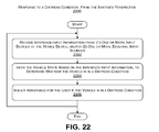
- FIG. 22 shows an illustrative procedure by which the distress management module of FIG. 16 can infer and respond to a distress condition that may affect the vehicle.
- FIG. 23 shows illustrative computing functionality that can be used to implement any aspect of the features shown in the foregoing drawings.
- Series 100 numbers refer to features originally found in FIG. 1
- series 200 numbers refer to features originally found in FIG. 2
- series 300 numbers refer to features originally found in FIG. 3 , and so on.
- Section A describes illustrative functionality for providing a user interface experience that depends on an inferred vehicle state.
- Section B describes illustrative methods which explain the operation of the functionality of Section A.
- Section C describes illustrative computing functionality that can be used to implement any aspect of the features described in Sections A and B.
- FIG. 23 provides additional details regarding one illustrative physical implementation of the functions shown in the figures.
- the phrase “configured to” encompasses any way that any kind of physical and tangible functionality can be constructed to perform an identified operation.
- the functionality can be configured to perform an operation using, for instance, software, hardware (e.g., chip-implemented logic functionality), firmware, etc., and/or any combination thereof.
- logic encompasses any physical and tangible functionality for performing a task.
- each operation illustrated in the flowcharts corresponds to a logic component for performing that operation.
- An operation can be performed using, for instance, software, hardware (e.g., chip-implemented logic functionality), firmware, etc., and/or any combination thereof.
- a logic component represents an electrical component that is a physical part of the computing system, however implemented.
- FIG. 1 shows an illustrative environment 100 in which users can operate mobile devices within vehicles.
- FIG. 1 depicts an illustrative user 102 who operates a mobile device 104 within a vehicle 106 , and a user 108 who operates a mobile device 110 within a vehicle 112 .
- the environment 100 can accommodate any number of users, mobile devices, and vehicles.
- this section will set forth the illustrative composition and manner of operation of the mobile device 104 operated by the user 102 , treating this mobile device 104 as representative of any mobile device's operation within the environment 100 .
- this explanation will state that the mobile device 104 performs certain processing functions. This statement is to be construed liberally.
- the mobile device 104 can perform a function by providing logic which executes this function. Alternatively, or in addition, the mobile device 104 can perform a function by interacting with a remote entity, which performs the function on behalf of the mobile device 104 .
- the mobile device 104 operates in at least two modes.
- a handheld mode of operation the user 102 can interact with the mobile device 104 while holding it in his or her hands.
- the user 102 can interact with a touch input device of the mobile device 104 and/or a keypad of the mobile device 104 to perform any device function.
- a vehicle mode of operation the user 102 can interact with the mobile device 104 in his or her vehicle 106 .
- the mobile device 104 automatically assesses the state of the vehicle 106 (i.e., the “vehicle state” according to the terminology used herein) based on inference-input information.
- the mobile device 104 presents a user interface experience based on the vehicle state, as set forth below in greater detail.
- the vehicle state of the vehicle state characterizes the manner in which the vehicle 106 is currently being operated by the user 102 .
- Some aspects of the vehicle state may directly pertain to the dynamics of the vehicle's movement. Such direct aspects can include, but are not limited to: the speed at which the vehicle 106 is traveling; the manner in which the vehicle 106 is being accelerated and decelerated; the manner in which the vehicle 106 is being steered; the manner in which the breaks of the vehicle 106 are being applied, and so on.
- Other aspects of the vehicle state may have a more indirect bearing on the manner in which the vehicle 106 is moving. For example, these aspects of the vehicle state may pertain to the qualifying circumstances in which vehicle 106 movement is taking place.
- Such indirect aspects can include, but are not limited to: the region in which the vehicle 106 is traveling; the time of day in which the vehicle 106 is traveling; the date at which the vehicle 106 is traveling; the weather through which the vehicle 106 is traveling; the road condition over which the vehicle 106 is traveling, and so forth.
- the mobile device 104 can determine the vehicle state based on inference-input information.
- the inference-input information pertains to any information that can be used to infer the vehicle state. Some of the inference-input information may originate from input sources which are internal to the mobile device 104 . Other inference-input information may originate from input sources which are external to the mobile device 104 .
- the vehicle state correlates to an attention profile.
- the attention profile characterizes a level of attention and a type of attention which is appropriate for the user 102 to maintain while driving within the vehicle state. For example, assume that the vehicle state indicates that the user 102 is traveling at a high rate of speed in a congested urban area. Based on these considerations, the mobile device 104 may reach the conclusion that it is appropriate for the user 102 to pay close attention to the task of operating the vehicle 106 . In contrast, assume that the vehicle state indicates that the user 102 is sitting in his vehicle 106 , stopped in a traffic jam. In this circumstance, the mobile device 104 can reach the conclusion that it is permissible for the user 102 to devote greater attention to supplemental non-driving-related tasks (compared to the first scenario).
- the mobile device 104 then presents a user interface experience that makes attention-related demands on the user 102 that are commensurate with the vehicle state.
- the mobile device 104 engages the user 102 in a manner that is appropriate in view of the attention profile of the vehicle state, e.g., by not demanding a level and type of attention that goes beyond what the user 102 can “afford” to provide while driving the vehicle 106 .
- the mobile device 104 can present a user interface experience which places few if any demands on the attention of the user 102 .
- the mobile device 104 can place far greater demands on the attention of the user 102 .
- the mobile device 104 can provide an appropriate user interface experience in different ways.
- a user interface experience refers to the manner in which a user 102 interacts with the mobile device 104 , either by providing user-input information to the mobile device 104 or receiving output information from the mobile device 104 .
- the manner in which the user 102 provides user-input information to the mobile device 104 is defined by various input modes that a user 102 can use to provide the user-input information to the mobile device 104 .
- Illustrative input modes can include a keypad input mode, a touch screen input mode, a voice-recognition input mode, a gesture-recognition input mode, and so on (to be described in greater detail below).
- the manner in which the mobile device 104 provides output information to the user is defined by various output modes.
- Illustrative output modes can include a display output mode, a speech output mode, and so on (to be described in greater detail below).
- the mobile device 104 can vary the user interface experience by activating and/or deactivating certain input modes and/or output modes. Alternatively, or in addition, the mobile device 104 can vary the user interface experience by changing the manner of operation of any input mode and/or any output mode (again, to be described in greater detail below).
- the mobile device 104 can be implemented in any manner and can perform any function or combination of functions.
- the mobile device 104 can correspond to a mobile telephone device of any type (such as a smart phone device), a book reader device, a personal digital assistant device, a laptop computing device, a tablet-type computing device, a netbook-type computing device, a portable game device, a portable media system interface module device, and so on.
- the vehicle 106 can correspond to any mechanism for transporting the user 102 .
- the vehicle 106 may correspond to an automobile of any type, a truck, a bus, a motorcycle, a scooter, a bicycle, an airplane, a boat, and so on.
- the vehicle 106 corresponds to a personal automobile operated by the user 102 .
- the environment 100 also includes a communication conduit 114 for allowing the mobile device 104 to interact with any remote entity (where a “remote entity” means an entity that is remote with respect to the user 102 ).
- a “remote entity” means an entity that is remote with respect to the user 102 ).
- the communication conduit 114 may allow the user 102 to use the mobile device 104 to interact with another user who is using another mobile device (such as the user 108 who is using the mobile device 110 ).
- the communication conduit 114 may allow the user 102 to interact with any remote services.
- the communication conduit 114 can represent a local area network, a wide area network (e.g., the Internet), or any combination thereof.
- the communication conduit 114 can be governed by any protocol or combination of protocols.
- the communication conduit 114 can include wireless communication infrastructure 116 as part thereof.
- the wireless communication infrastructure 116 represents the functionality that enables the mobile device 104 to communicate with remote entities via wireless communication.
- the wireless communication infrastructure 116 can encompass any of cell towers, base stations, central switching stations, satellite functionality, and so on.
- the communication conduit 114 can also include hardwired links, routers, gateway functionality, name servers, etc.
- the environment 100 also includes one or more remote processing systems 118 .
- the remote processing systems 118 provide any type of services to the users.
- each of the remote processing systems 118 can be implemented using one or more servers and associated data stores.
- FIG. 1 shows that the remote processing systems 118 can include at least one instance of remote processing functionality 120 and an associated system store 122 .
- the ensuing description will set forth illustrative functions that the remote processing functionality 120 can perform that are germane to the operation of the mobile device 104 within the vehicle 106 .
- FIG. 2 shows a portion of a representative interior region 200 of the vehicle 106 .
- a mount 202 secures the mobile device 104 within the interior region 200 . More specifically, the mount 202 secures the mobile device 104 to the top of the vehicle's dashboard, to the left of the user 102 , just above the vehicle control panel region 204 .
- a power cord 206 supplies power from any power source provided by the vehicle 106 to the mobile device 104 (either directly or indirectly, as will be described in connection with FIG. 7 ).
- the mobile device 104 can include at least one internal camera device (not shown in FIG. 2 ) having a field of view that projects out from a face of the mobile device 104 , towards the user 102 . More specifically, the user 102 can place the mobile device 104 within the interior region 200 in such a manner that the field of view of the camera device encompasses at least a part of the anatomy of the user 102 . In one implementation, this placement enables the internal camera device to establish an interaction space. The internal camera device can capture gestures made by the user 102 within that interaction space.
- the interaction space may generally correspond to a conic volume that extends approximately 60 cm from the face of the mobile device 104 , pointed towards the user 102 who is driving the vehicle 106 (although different end-use environments can adopt interaction spaces having different “sizes” and shapes).
- the placement of the mobile device 104 shown in FIG. 2 is merely representative, meaning that the user 102 can choose other locations and orientations of the mobile device 104 .
- the user 102 can place the mobile device 104 in a left region with respect to the steering wheel, instead of a right region with respect to the steering wheel (as shown in FIG. 2 ). This might be appropriate, for example, in countries in which the steering wheel is provided on the right side of the vehicle 106 .
- the user 102 can place the mobile device 104 directly behind the steering wheel or on the steering wheel.
- the user 102 can secure the mobile device 104 to the windshield of the vehicle 106 .
- FIG. 3 shows one merely representative mount 302 that can be used to secure the mobile device 104 to some surface of the interior region 200 of the car.
- this mount 302 is a different type of mount than the mount 202 shown in FIG. 2 ).
- the mount 302 of FIG. 3 includes any type of coupling mechanism 304 for fastening the mount 302 to a surface within the interior region 200 .
- the coupling mechanism 304 can include a clamp or protruding member (not shown) that attaches to an air movement grill of the vehicle 106 .
- the coupling mechanism 304 can include a plate or other type of member which can be fastened to any surface of the vehicle 106 using any type of fastener (e.g., screws, clamps, a Velcro coupling mechanism, a sliding coupling mechanism, a snapping coupling mechanism, a suction cup coupling mechanism, etc.).
- the mount 302 can merely sit on a generally horizontal surface of the interior region 200 , such as on the top of the dashboard, without being fastened to that surface. To reduce the risk of this type of mount sliding on the surface during movement of the vehicle 106 , it can include a weighted member, such as a sand-filled malleable base member.
- the representative mount 302 shown in FIG. 3 includes a flexible arm 306 which extends from the coupling mechanism 304 and terminates in a cradle 308 .
- the cradle 308 can include an adjustable clamp mechanism 310 for securing the mobile device 104 to the cradle 308 .
- the user 102 has attached the mobile device 104 to the cradle 308 so that it can be operated in a portrait mode. But the user 102 can alternatively attach the mobile device 104 so that it can be operated in a landscape mode (as shown in FIG. 2 ).
- the mobile device 104 includes at least one internal camera device 312 which projects out from a front face 314 of the mobile device 104 (or other face of the mobile device 104 ).
- the internal camera device 312 is identified as “internal” insofar as it is typically considered an integral part of the mobile device 104 .
- the mobile device 104 can receive image information from one or more external camera devices (not shown).
- the mount 302 may incorporate any attachment-sensing mechanism 316 for determining when the mobile device 104 has been inserted in the cradle 308 of the mount 302 .
- the attachment-sensing mechanism 316 can comprise a mechanical switch that that is toggled from an OFF to an ON state when the user 102 inserts the mobile device 104 into the cradle 308 , and from an ON to OFF state when the mobile device 104 becomes dislodged from the cradle 308 .
- Other implementations of the attachment-sensing device include a light-sensing switch, a pressure-sensing switch, and so on.
- the mobile device 104 can implement an attachment sensing mechanism (not shown).
- a device-implemented attachment sensing mechanism is configured to be activated when the user 102 places the mobile device 104 in the cradle 308 .
- the mobile device 104 can infer the fact that it has become dislodged from the cradle 308 based on indirect evidence.
- the attachment-sensing mechanism 316 plays a role in determining whether the vehicle 106 is in a distress condition.
- the mount 302 can include one or more supplemental sensor devices 320 (depicted generically in FIG. 3 by a dashed box).
- the sensor devices 320 can encompass one or more of the types of movement-sensing devices 430 shown in FIG. 5 (to be described below).
- the mount 302 can encompass additional image-sensing mechanisms, such one or more additional camera devices of any type, etc.
- FIG. 4 shows various components that can be used to implement the mobile device 104 . This figure will be described in a generally top-to-bottom manner.
- the mobile device 104 includes communication functionality 402 for receiving and transmitting information to remote entities via wireless communication. That is, the communication functionality 402 may comprise a transceiver that allows the mobile device 104 to interact with the wireless communication infrastructure 116 of the communication conduit 114 .
- the mobile device 104 can also include a set of one or more applications 404 .
- the applications 404 represent any type of functionality for performing any respective tasks. In some cases, the applications 404 perform high-level tasks. To cite representative examples, a first application may perform a map navigation task, a second application can perform a media presentation task, a third application can perform an Email interaction task, and so on. In other cases, the applications 404 perform lower-level management or support tasks.
- the applications 404 can be implemented in any manner, such as by executable code, script content, etc., or any combination thereof.
- the mobile device 104 can also include at least one device store 406 for storing any application-related information, as well as other information.
- At least part of the applications 404 can be implemented by the remote processing systems 118 .
- some of the applications 404 may represent network-accessible pages and/or other type of functionality.
- the mobile device 104 can also include a device operating system 408 .
- the device operating system 408 provides functionality for performing low-level device management tasks. Any application can rely on the device operating system 408 to utilize various resources provided by the mobile device 104 .
- the mobile device 104 can also include input functionality 410 for receiving and processing input information.
- the input functionality 410 includes some functionality for receiving input information from internal input devices (which represent components that are part of the mobile device 104 itself), and some functionality for receiving input information from external input devices.
- the input functionality 410 can receive input information from external input devices using any coupling technique or combination of coupling techniques, such as hardwired connections, wireless connections (e.g., Bluetooth® connections), and so on.
- This explanation refers to the input information that is ultimately used to infer the state of the vehicle 106 as inference-input information.
- This explanation refers to the input information that is provided by the user 102 as user-input information.
- These two classes of input information are not necessarily mutually exclusive; that is, some of the information that is input by a user 102 may constitute inference-input information.
- a generic reference to “input information,” without the qualifier “user” or “inference,” refers to any type of input information.
- the input functionality 410 includes an optional gesture recognition module 412 for receiving image information from at least one internal camera device 414 , and/or from at least one external camera device 416 .
- the external camera device 416 can be associated with the mount 302 , or by some other unit within the vehicle 106 .
- Any of these camera devices can provide any type of image information.
- a camera device can provide video image information, produced by receiving visible-spectrum radiation, infrared-spectrum radiation, etc., or combination thereof.
- a camera device can provide image information that can be further processed to provide depth information. Depth information provides an indication of the distances between different points in a captured scene and a reference point (e.g., corresponding to the location of the camera device).
- Depth processing functionality can generate depth information using any technique, such as a time-of-flight technique, a structured light technique, a stereoscopic technique, and so on.
- the gesture recognition module 412 can determine whether the image information reveals that the user 102 has made a recognizable gesture.
- the input functionality 410 can also receive image information from one or more camera devices that capture a scene that is external to the vehicle 106 .
- an internal or external camera device can capture a scene in front of the vehicle 106 , in back of the vehicle 106 , to either side of the vehicle 106 , etc.
- These camera devices can also be used in conjunction with any type depth processing functionality described above.
- the use of depth processing functionality allows the mobile device 104 to assess the distance between the vehicle 106 and other nearby vehicles and obstacles.
- the input functionality 410 can also receive inference-input information from any other type of distance sensing mechanism, such as a Light Detection And Ranging (LIDAR) sensing device, etc.
- LIDAR Light Detection And Ranging
- the input functionality 410 can also include a supplemental system interface module 418 .
- the supplemental system interface module 418 receives inference-input information from any vehicle system 420 , and/or from the mount 302 , and/or from any other external system.
- the supplemental system interface module 418 can receive any type of OBDII information provided by the vehicle's information management system. Such information can describe the operating state of the vehicle 106 at a particular point in time, such as by providing information regarding the vehicle's speed, steering state, breaking state, engine temperature, engine performance, odometer reading, oil level, fuel level, the presence of passengers in the vehicle 106 , and so on.
- the vehicle system 420 can receive sensor information from a plurality of sensing devices provided by the vehicle 106 .
- the supplemental system interface module 318 can receive inference-input information collected by one or more sensor devices (such as one or more supplemental accelerometer devices provided by the mount 302 ).
- the input functionality 410 can also include a touch input module 422 for receiving user-input information when a user 102 touches a touch input device 424 .
- the input functionality 410 can also include any type of physical keypad input mechanism, any type of joystick control mechanism, any type of mouse device mechanism, and so on.
- the input functionality 410 can also include a voice recognition module 426 for receiving voice commands from one or more microphone devices 428 .
- the input functionality 410 can also include one or more movement-sensing devices 430 .
- the movement-sensing devices 430 determine the manner in which the mobile device 104 is being moved at any given time. That information, in turn, can pertain to either the dynamic movement of the mobile device 104 and/or its position at any given time. Advancing momentarily to FIG.
- the movement-sensing devices 430 can include any of an accelerometer device 502 , a gyro device 504 , a magnetometer device 506 , a GPS device 508 (or other satellite-based position-determining mechanism), a dead-reckoning position-determining device (not shown), a cell tower or WiFi triangulation device (not shown), and so on.
- the movement-sensing device 430 can include any type of vision device described above, e.g., corresponding to one or more camera devices and associated functionality. That is, the images captured by the vision device comprise evidence regarding the movement of the vehicle 106 ; therefore, the vision device can be considered as a type of movement-sensing device. This set of possible devices is representative, rather than exhaustive. In other cases, some other entity (besides, or in addition to the mobile device 104 ) can assess the movement of the mobile device 104 , such as any functionality provided by the remote processing systems 118 .
- the mobile device 104 also includes output functionality 432 for conveying information to a user 102 in an output presentation.
- output functionality 432 can include any of a device screen 602 , one or more speaker devices 604 , a projector device 606 for projecting output information onto any surface, and so on.
- the output functionality 432 also includes a vehicle interface module 608 that enables the mobile device 104 to send output information to any vehicle system 420 associated with the vehicle 106 .
- This allows the user 102 to interact with the mobile device 104 to control the operation of any functionality associated with the vehicle 106 itself.
- the user 102 can interact with the mobile device 104 to control the playback of media content on a separate vehicle media system.
- the user 102 may prefer to directly interact with the mobile device 104 rather than the systems of the vehicle 106 because the user 102 is presumably already familiar with the manner in which the mobile device 104 operates.
- the mobile device 104 has access to a remote system store 122 which can provide user-specific information. The mobile device 104 can leverage this information to control any vehicle system 420 in a manner that is customized for a particular user 102 .
- the mobile device 104 can optionally include mode functionality 434 .
- the mode functionality 434 performs the core functions summarized above, which include assessing the state of the vehicle 106 at a particular point in time and providing a user interface experience that takes into consideration the vehicle state.
- at least parts of the mode functionality 434 can be implemented by the remote processing systems 118 .
- FIG. 7 illustrates one manner in which the functionality provided by the mount 302 (of FIG. 3 ) can interact with the mobile device 104 .
- the mount 302 can include the attachment sensing mechanism 316 (described above) which provides an attachment signal to the input functionality 410 of the mobile device 104 .
- the attachment signal indicates whether or not the mobile device 104 is presently coupled to the mount 302 .
- the mount 302 can also include any of the type of the movement-sensing devices 430 shown in FIG. 5 for providing inference-input information to the input functionality 410 of the mobile device 104 .
- the mount 302 can also include any other optional devices 702 for providing inference-input information to the input functionality 410 of the mobile device 104 .
- the devices 702 can perform various processing functions, and can then send the results of such processing to the mobile device 104 .
- the mount 302 can also include a power source 704 which feeds power to the mobile device 104 , e.g., via an external power interface module 706 provided by the mobile device 104 .
- the power source 704 may, in turn, receive power from any external source, such as a power source (not shown) associated with the vehicle 106 .
- the power source 704 powers both the components of the mount 302 and the mobile device 104 .
- each of the mobile device 104 and the mount 302 can be supplied with separate sources of power.
- FIG. 7 shows interfaces ( 708 , 710 ) that allow the input functionality 410 of the mobile device 104 to communicate with the components of the mount 302 .
- FIGS. 8 and 9 pictorially summarize two output modes. That is, in FIG. 8 , the mobile device 104 presents visual content 802 on the display screen 602 of the mobile device 104 . In FIG. 9 the mobile device 104 presents audio content 902 that supplements or replaces the visual content 802 .
- FIGS. 10-12 pictorially summarize three input modes. That is, in FIG. 10 , the touch input module 422 accepts user-input information when the user 102 uses a hand 1002 to touch an icon 1004 or other object presented on a touch input screen of the mobile device 104 .
- the gesture recognition module 412 receives user-input information when the user 102 makes a gesture that is captured by the internal camera device 414 of the mobile device 104 , without touching the mobile device 104 .
- the gesture recognition module 412 can recognize this gesture by comparing the captured image information with candidate gesture information associated with each of a set of possible candidate gestures.
- the voice recognition module 426 receives user-input information when the user 102 annunciates a voice command.
- FIG. 13 shows additional information regarding a subset of the components of the mobile device 104 , introduced above in the context of FIGS. 4-7 .
- the components include a representative application 1302 and the mode functionality 434 .
- the “representative application” 1302 represents one of the set of applications 404 that may run on the mobile device 104 (and/or may run on remote processing functionality).
- FIG. 13 depicts the representative application 1302 and the mode functionality 434 as separate entities that perform respective functions.
- any aspect of the mode functionality 434 can be alternatively, or in addition, be performed by the representative application 1302 .
- any aspect of the representative application 1302 can alternatively, or in addition, be performed by the mode functionality 434 .
- the components shown in FIG. 13 are described herein as being performed by the mobile device 104 .
- at least some of the functions of the representative application 1302 and the mode functionality 434 can be performed by any functionality of the remote processing systems 118 and/or the mount 302 .
- the representative application 1302 can be conceptualized as comprising a set of resources 1304 .
- the application resources 1304 represent image content, text content, audio content, programmatic content, control settings, etc. that the representative application 1302 may use to provide its services.
- a developer can provide multiple collections of resources for invocation in different vehicle states. For example, assume that there are two principal vehicle states: moving and not moving. The developer can provide a first collection of interface icons and prompting messages that the mobile device 104 can present in the moving state, and a second collection of interface icons and prompting messages that the mobile device 104 can present in a non-moving state. The moving-state collection can differ from the non-moving-state collection.
- the moving-state collection can use larger size icons and fonts compared to the non-moving-state collection.
- the mode functionality 434 can determine the vehicle state at a particular time. In response, the mode functionality 434 can invoke the moving-collection collection to provide a user interface experience in the moving state and the non-moving-collection to provide a user interface experience in the non-moving state. (As will be described below, the mode functionality 434 can make other changes to produce an appropriate user interface experience.)
- the two-collection example is merely illustrative; other applications can provide more than two classes of resource collections corresponding to different respective ways in which the vehicle 106 is being driven.
- a developer can create a resource collection for use for a nighttime driving vehicle state and a resource collection for a daytime driving vehicle state (as well as a resource collection for a non-moving state).
- the developer can consult an appropriate software development kit (SDK) to assist him or her in creating the different sets of resources.
- SDK software development kit
- the SDK describes various requirements and recommendations regarding the characteristics of resources to be used in different vehicle states. For example, the SDK can require or recommend that the developer use fonts no smaller than a certain size for certain vehicle states.
- the mode functionality 434 this component is shown as comprising three sub-modules: an interface module 1306 , a state detection module 1308 , and an experience presentation module 1310 . To facilitate description, it will be assumed that all of the logic for implementing these three functions is indeed encapsulated in a unit being referred to as the mode functionality 434 . But as stated above, any aspect of the mode functionality 434 can be alternatively, or in addition, performed by the representative application 1302 and/or some other entity (such as the remote processing systems 118 ).
- the interface module 1306 receives various forms of inference-input information.
- a subset 1312 of the instances of inference-input information originates from input sources that are associated with the mobile device 104 itself
- Another subset 1314 of the instances of inference-input information originates from input sources that are external to the mobile device 104 (e.g., from the vehicle system 420 , the mount 302 , etc.).
- the subset 1312 of internal instances of inference-input information can originate from any of the movement-sensing devices 430 enumerated in FIG. 5 .
- the subset 1312 can also include image information received from one or more internal camera devices which capture a scene or scenes inside the vehicle 106 and/or outside the vehicle 106 .
- the subset 1312 can also include audio information captured by one or more microphone devices.
- the subset 1314 of instances of external inference-input information can originate from any sensor devices which feed sensor information into any vehicle system 420 , e.g., as expressed by OBDII information or the like.
- the subset 1314 can also include image information received from one or more external camera devices which capture a scene or scenes inside the vehicle 106 and/or outside the vehicle 106 .
- image information captured by an outward-pointing camera device can be used to reveal the presence of pedestrians and nearby vehicles, the presence of stop lights, and so on.
- the subset 1314 can also include audio information captured by one or more microphone devices.
- This subset 1314 can also encompass any information that is extracted from a remote source (e.g., from any of the remote processing systems 118 ).
- information can include map information, traffic information, road condition information, hazard information, weather information, region population information, point of interest information, legal information regarding driving-related rules pertinent to a particular jurisdiction, and so on.
- the map information can provide information regarding a region in any level of granularity. For example, the map information can identify the location of traffic lights, complex intersections, school zones, etc. in a region.
- the information maintained by the remote processing systems 118 can be collected in various ways.
- the remote processing systems 118 can collect the information based on in-field sensing devices, such as roadway camera devices, aerial and satellite camera devices, temperature sensing devices, precipitation-sensing devices, and so forth.
- the remote processing systems 118 can collect the information from human observers who manually report the information.
- the remote processing systems 118 can collect the information by crowd-sourcing it from a plurality of mobile devices provided in respective vehicles.
- inference-input information are cited by way of illustration, not limitation; other implementations can provide other forms of inference-input information, and/or can omit one or more forms of inference-input information described above.
- the state detection module 1308 infers the state of the vehicle 106 based on any combination of the forms of inference-input information enumerated above (and/or other forms of inference-input information).
- the state detection module 1308 can perform this task in different ways.
- the state detection module 1308 can maintain a lookup table which maps different permutations of input conditions (defined by the inference-input information) to corresponding vehicle state information. That is, the state detection module 1308 can indicate that, if input conditions L, M, N, and P are present, the vehicle state is in state X.
- the state detection module 1308 can use a statistical model to map a feature vector associated with a set of input conditions into an identified vehicle state.
- That statistical model can be produced in a machine-learning process.
- the state detection module 1308 can use a rules-based engine of any type or a neural network to map the input conditions into an identified vehicle state, and so on. These implementations are cited by way of example, not limitation. Section B will describe the illustrative behavior of the state detection module 1308 in greater detail, in the context of representative scenarios.
- the state detection module 1308 can consult a route prediction module to determine the route that the user 102 is likely to take to reach a specified or predicted destination.
- the route information helps the state detection module 1308 operate in a more proactive manner by predicting difficult driving conditions that the user 102 is likely to confront as the trip progresses, before those conditions are actually encountered.
- the state detection module 1308 can also mine any other user resources in order to generate the vehicle state, such as calendar information, purchase history information, prior travel route information, and so on.
- the experience presentation module 1310 receives information regarding the inferred vehicle state from the state detection module 1308 . In response, the experience presentation module 1310 maps the vehicle state into a user interface experience.
- the mode functionality 434 attempts to provide a user interface experience which consumes the attention of the user 102 in a way that is commensurate with the vehicle state. This means that that the user interface experience is such that it does not demand a level and type of attention from the user 102 that the user 102 cannot safely give in view of the vehicle state. This behavior, in turn, ultimately reduces the risk associated with the use of the mobile device 104 within the vehicle 106 .
- the mode functionality 434 provides a user experience that is not unduly restrictive, e.g., by unnecessarily precluding certain interactions that do not pose a significant risk to the user 102 .
- the experience presentation module 1310 can also consult functionality provided in the remote processing systems 118 (and its associated system store 122 ) to choose the user interface experience that it presents to the user 102 . For example, the experience presentation module 1310 can determine the preferences and habits of the user 102 , and then use this information to influence the selection of the user interface experience.
- the preferences may indicate the configurations of the user interface experience which the user prefers to receive in different driving circumstances.
- the experience presentation module 1310 may attempt to satisfy a preference of the user for a particular driving circumstance, providing that such a choice is not contradicted by other considerations.
- the habits can indicate the manner in which the user has driven the vehicle 106 (on past occasions) when confronted with various driving circumstances in conjunction with different user interface experiences. If the user performed poorly for a particular combination of a driving circumstance and a user interface experience, the experience presentation module 1310 can negatively weight this combination to disfavor its use on a future occasion.
- the experience presentation module 1310 can present warnings to the user. For example, a warning may alert the user to the fact that he or she is approaching a school zone. The warning may encourage the driver to be watchful for the presence of children. In addition, or alternatively, the warning may alert the user that he or she is driving too fast for the circumstances.
- FIG. 14 enumerates some of the different ways that the experience presentation module 1310 can produce a desired user interface experience.
- (Section B will describe yet more examples of the operation of the experience presentation module 1310 .)
- the experience presentation module 1310 can adjust some aspect of the output functionality 432 .
- the experience presentation module 1310 can adjust some aspect of the input functionality 410 .
- the experience presentation module 1310 can also modify any other aspect of the environment 100 shown in FIG. 1 .
- the experience presentation module 1310 can enable or disable certain output modes in response to the vehicle state (or at least partially enable or restrict one or more parts of certain output modes).
- the experience presentation module 1310 can disable a display output mode when the vehicle 106 is moving.
- the experience presentation module 1310 can provide output information via the speech output mode, or produce no output information at all so long as the moving condition prevails.
- the experience presentation module 1310 can change the content that it presents in response to the vehicle state.
- an application can include two or more collections of resources for use in providing an output presentation.
- the experience presentation module 1310 can present an output presentation using an appropriate collection of resources based on the vehicle state.
- the experience presentation module 1310 can display large-sized icons when the speed of the vehicle 106 exceeds a prescribed threshold.
- the experience presentation module 1310 can change any property or properties of the output presentation itself in response to vehicle state. This type of change is similar to the one described immediately above. But here, instead of choosing an entirely new collection of resources, the experience presentation module 1310 can modify one or more variable attributes of the output presentation. This category encompasses a wide range of options. For example, for visual output presentations, the experience presentation module 1310 can adjust any of the size, contrast, color, transparency, etc. of the content that is displayed, the length of time that the content is displayed, the spatial organization between different parts of the content that is displayed, and so on. For audio output presentations, the experience presentation module 1310 can adjust the volume of the audio content that is presented, the rate of speaking provided by the audible content, and so on.
- the experience presentation module 1310 can send output information to different destinations based on the vehicle state. For example, for some vehicle states, the mobile device 104 may route the output information to an output device associated with the mobile device 104 itself. For other vehicle states, the mobile device 104 may route the output information to any vehicle system 420 , such as a media system associated with the vehicle 106 .
- the experience presentation module 1310 can use yet other strategies for modifying any output presentation based on vehicle state.
- the experience presentation module 1310 can enable or disable certain input modes (or at least partially enable or restrict one or more parts of certain input modes).
- the experience presentation module 1310 can disable the touch screen input mode and the keypad input mode when the vehicle 106 is moving at a high speed.
- the experience presentation module 1310 can provide input via the voice-recognition input mode and/or the gesture-recognition input mode.
- the experience presentation module 1310 can change the type of user-input information that is obtained based on vehicle state. For example, the experience presentation module 1310 can accept a fewer number of voice commands while the vehicle 106 is traveling at high speeds, compared to when the vehicle 106 is moving at slower speeds. This change can help reduces the complexity of the voice-recognition input mode at higher speeds, and hence the distraction that this mode may impose on the user 102 .
- the experience presentation module 1310 can change the manner in which any input mode collects user-input information. For example, at certain junctures, an input mode may present a query to the user 102 , requiring a response; after a certain amount of time without receiving an answer, the input mode can deactivate the query. At higher speeds, the input mode can extend the length of time for which it solicits a response from the user 102 , as the user 102 may be distracted and unable to provide a quick answer.
- the experience presentation module 1310 can use yet other strategies for modifying any input mode based on vehicle state.
- FIG. 15 shows another environment 1500 in which the user 102 can operate his or her mobile device 104 within the vehicle 106 .
- the environment 1500 determines when the vehicle 106 appears to be in a distress condition.
- a distress condition corresponds to any traumatic event that befalls the vehicle 106 , and by extension, the user 102 who is driving the vehicle 106 .
- a distress condition may correspond to an accident that has occurred that involves the vehicle 106 .
- the environment 1500 solicits help from a diver assistance system 1502 .
- the driver assistance system 1502 can help the user 102 in various ways, such as by: (a) contacting the user 102 by telephone, text messaging, or other communication mechanism; (b) contacting an emergency response service (or services); (c) contacting the user's family members or other designated points of contact; (d) providing information regarding service stations and/or other assistance centers, and so on. Whenever the driver assistance system 1502 notifies a party of the occurrence of the distress condition, it can identify the location of the vehicle 106 and any qualifying circumstances surrounding the distress condition.
- the driver assistance system 1502 may be staffed by human agents who assist the user 102 in the event of a distress condition.
- the driver assistance system 1502 can include automated functionality for assisting the user 102 .
- FIG. 16 provides additional information regarding a distress management module 1602 that can detect and respond to a distress condition within the environment 1500 of FIG. 15 .
- the mobile device 104 implements the distress management module 1602 .
- the remote processing systems 118 and/or mount 302 can implement at least part of the distress management module 1602 .
- the distress management module 1602 includes an interface module 1604 that receives a subset 1606 of instances of inference-input information from one or more internal input sources and/or a subset 1608 of instances of inference-input information from one or more external input sources.
- the interface module 1604 functions in the same manner as the interface module 1306 of FIG. 13 .
- a distress condition detection module 1610 analyzes the input information to determine whether a distress condition has occurred. Different environments can make this judgment in different ways. Generally, the distress condition detection module 1610 forms a signature from the various instances of inference-input information that have been received, and then determines whether this signature matches the telltale signature of a distress condition. In one case, the distress condition detection module 1610 determines that a distress condition has occurred if: (1) the mobile device 104 is present in the vehicle 106 ; and (2) the vehicle 106 came to an abrupt stop or otherwise abruptly decelerated (or accelerated); and/or (3) the mobile device 104 became dislodged from the mount 302 at about the same time as the occurrence of the abrupt deceleration (or acceleration).
- a jolting deceleration may indicate that the moving vehicle 106 has collided with an object in its path.
- a jolting acceleration may indicate that the vehicle 106 has been hit by another moving object, including while the vehicle 106 is originally at rest.
- the distress condition detection module 1610 can presume that the mobile device 104 is located in the vehicle 106 if, just prior to the abrupt deceleration, the attachment-sensing mechanism 316 indicates that the mobile device 104 is inserted in the cradle 308 of the mount 302 . Likewise, the distress condition detection module 1610 can determine that the mobile device 104 has broken free of the mount 302 based on the output of the attachment-sensing mechanism 316 . The distress condition detection module 1610 can determine that the mobile device 104 has come to an abrupt stop or otherwise abruptly decelerated (or accelerated) based on the output of the accelerometer device 502 , for example.
- the distress condition detection module 1610 can indicate the occurrence of a distress condition without the occurrence of events (2) and/or (3).
- the distress condition detection module 1610 take into consideration any of the following events in assessing the occurrence of a distress condition: (a) a dramatic application of the breaks; (b) erratic steering; (c) traversal of significantly uneven surfaces (as when the vehicle 106 veers off a roadway); (d) the vehicle 106 turning on its side or completely overturning, etc.
- the distress condition detection module 1610 can base its analysis on image information captured by one or more camera devices and/or audio information captured by one or more microphone devices. These events are cited by way of illustration, not limitation.
- An action module 1612 can notify the driver assistance system 1502 when the distress condition detection module 1610 informs it that a distress condition has occurred.
- An assistance center interaction module 1614 allows the user 102 to subsequently communicate with the driver assistance system 1502 to receive manual and/or automated help from that entity.
- the mode functionality 434 provides a particularly useful service in those environments in which the user 102 may interact with the mobile device 104 in different use scenarios, and further where the user 102 has different respective capabilities of interacting with the mobile device 104 in these different scenarios.
- the mobile device 104 can determine whether the user 102 is interacting with the mobile device 104 while walking or running; if so, the mobile device 104 can present a user interface experience to the user 102 which takes into consideration various constraints to which the user 102 may be subject while walking or running (as opposed to interacting with the mobile device 104 while at a single location).
- FIGS. 17-22 show procedures that explain one manner of operation of the environment 100 of FIG. 1 . Since the principles underlying the operation of the environment 100 have already been described in Section A, certain operations will be addressed in summary fashion in this section.
- this figure shows an illustrative procedure 1700 that sets forth one manner of operation of the environment 100 of FIG. 1 , from the perspective of the user 102 .
- the user 102 may use his or her mobile device 104 in a conventional mode of operation, e.g., by using his or her hands to interact with the mobile device 104 using the touch input device 424 .
- the user 102 enters the vehicle 106 and places the mobile device 104 in any type of mount, such as the mount 302 .
- the user 102 instructs the mobile device 104 to operate in the vehicle mode.
- the user 102 begins navigation using the vehicle 106 .
- the user 102 receives a user interface experience that is tailored to a current vehicle state.
- the vehicle state is based on input information supplied by various input sources.
- the user 102 may remove the mobile device 104 from the mount 302 . The user 102 may then resume using the mobile device 104 in a normal handheld mode of operation.
- FIG. 18 shows an illustrative procedure 1800 which explains one manner of operation of the mode functionality 434 , from the perspective of the mode functionality 434 .
- the mode functionality 434 receives inference-input information from one or more input sources, including one or more internal input sources (e.g., corresponding to the movement-sensing devices 430 ), and/or one or more external input sources (e.g., corresponding to sensor information provided by a vehicle system 420 ).
- the mode functionality 434 infers the vehicle state based on the inference-input information.
- the mode functionality 434 presents a user interface experience based on the inferred driving state.
- FIGS. 19-21 show three instantiations of the procedure 1700 of FIG. 17 .
- FIG. 19 presents a scenario that hinges on whether the vehicle 106 is moving or not.
- the mode functionality 434 receives inference-input information.
- the mode functionality 434 determines whether the vehicle 106 is moving or not.
- the mode functionality 434 can make any combination of the changes summarized in FIG. 8 .
- the mode functionality 434 can use the inference-input information provided by any of the movement-sensing devices 430 and/or external sensor devices to determine that the vehicle 106 is in motion. In response, the mode functionality 434 can terminate the use of the display input mode, or use the display input mode to present simplified content (compared to the content it would present if the vehicle 106 was stationary). In lieu of the display input mode, the mode functionality 434 can optionally interact with the user 102 using the voice-recognition mode and/or the gesture-recognition input mode. Alternatively, the mode functionality 434 can preclude the presentation of certain types of content, such as video content, while the vehicle 106 is in motion.
- FIG. 20 presents a scenario that depends on the manner in which the user 102 is driving the vehicle 106 .
- the mode functionality 434 receives inference-input information.
- the mode functionality 434 classifies the manner in which the mobile device 104 is moving based on the inference-input information.
- the mode functionality 434 can make any combination of the changes summarized in FIG. 8 .
- the mode functionality 434 can use any combination of inference-input information to compile a movement signature that characterizes the manner in which the device is moving. The mode functionality 434 can then compare this movement signature to telltale movement signatures associated with different classes of movement; a matching telltale signature indicates the type of movement that the vehicle 106 is currently undergoing.
- Such classes of movement can include (but are not limited to): (a) traveling at speeds over a prescribed threshold; (b) traveling at dramatically varying speeds; (c) traveling over a winding roadway; (d) traveling over a roadway with marked elevation changes; (e) traveling over an uneven surface; (f) making frequent lane changes while traveling; (g) frequently applying the breaks of the vehicle 106 while traveling; (h) frequently shifting gears while traveling (i) drifting over the roadway while traveling or traveling in an otherwise erratic manner, and so on.
- the mode functionality 434 can then apply a user interface experience which correlates to the matching telltale movement signature.
- the mode functionality 434 will seek to reduce the attention-related demands that it imposes on the user 102 .
- the mode functionality 434 will seek to lessen the attention-related burden on the user 102 .
- FIG. 21 presents a scenario that depends on an assessed location of the vehicle 106 .
- the mode functionality 434 receives inference-input information.
- the inference-input information can include any evidence pertaining to the location of the vehicle 106 .
- Such evidence can include position information, such as GPS information, WiFi or cell tower triangulation information, dead reckoning information, and so on.
- the mode functionality 434 can directly monitor the environment in which the user 102 is traveling based on image information captured by one or more camera devices and/or audio information captured by one or more microphone devices.
- the mode functionality 434 identifies the region in which the vehicle 106 is located based on the inference-input information. This can comprise position-related analysis of position information received by any position-determining device. For example, this operation may involve determining a street location of the vehicle 106 by consulting map information that is provided by the mobile device 104 and/or the remote processing systems 118 . The determination of the region can also involve analysis of image information received from camera devices and/or analysis of audio information received from microphone devices. For example, the mode functionality 434 can rely on image analysis to determine that the roadway on which the user 102 is traveling is congested with pedestrians and/or other vehicles.
- the mode functionality 434 can ascertain the driving-related implications of the region in which the vehicle 106 is located. In one implementation, the mode functionality 434 can make this assessment by consulting the remote processing systems 118 (and the associated system store 122 ). The remote processing systems 118 can determine whether there are any attention-related considerations that have a bearing on the amount and type of attention that a user 102 is expected to maintain while in the identified region. Based on this information, in block 2106 , the mode functionality 434 can make any combination of the changes summarized in FIG. 8 .
- the mode functionality 434 can ascertain whether the user 102 is within any one or the following representative regions to which a particular attention profile may apply: (a) a school zone; (b) a construction zone; (c) an area in proximity to emergency services; (d) a hazard zone, and so on. More generally, the mode functionality can also use any position-related evidence to determine the driving rules which are applicable to the vehicle 106 at a particular point in time. The mode functionality 434 can then apply a user interface experience which it appropriate for the identified region.
- the mode functionality 434 can make its determination of the vehicle state based on the manner in which the user 102 is driving his or her vehicle 106 (as ascertained in scenario A or scenario B), combined with insight regard the present location of the vehicle 106 (as ascertained in scenario C). For example, the mode functionality 434 can selectively disable a display input mode output presentation when the user 102 is driving more than 20 MPH on a street that borders a park.
- FIG. 22 shows a procedure 2200 which summarizes one manner of operation of the distress management module 1602 shown in FIG. 16 .
- the distress management module 1602 receives inference-input information.
- the distress management module 1602 determines whether the vehicle 106 is in a distress condition at the present time, based on the inference-input information.
- the distress management module 1602 presents assistance to the user 102 (presuming that the vehicle 106 is in a distress condition). This assistance can include contacting the remote driver assistance system 1502 .
- FIG. 23 sets forth illustrative computing functionality 2300 that can be used to implement any aspect of the functions described above.
- the computing functionality 2300 can be used to implement any aspect of the mobile device 104 .
- the type of computing functionality 2300 shown in FIG. 23 can be used to implement any aspect of the remote processing systems 118 .
- the computing functionality 2300 may correspond to any type of computing device that includes one or more processing devices. In all cases, the computing functionality 2300 represents one or more physical and tangible processing mechanisms.
- the computing functionality 2300 can include volatile and non-volatile memory, such as RAM 2302 and ROM 2304 , as well as one or more processing devices 2306 (e.g., one or more CPUs, and/or one or more GPUs, etc.).
- the computing functionality 2300 also optionally includes various media devices 2308 , such as a hard disk module, an optical disk module, and so forth.
- the computing functionality 2300 can perform various operations identified above when the processing device(s) 2306 executes instructions that are maintained by memory (e.g., RAM 2302 , ROM 2304 , or elsewhere).
- instructions and other information can be stored on any computer readable medium 2310 , including, but not limited to, static memory storage devices, magnetic storage devices, optical storage devices, and so on.
- the term computer readable medium also encompasses plural storage devices. In all cases, the computer readable medium 2310 represents some form of physical and tangible entity.
- the computing functionality 2300 also includes an input/output module 2312 for receiving various inputs (via input modules 2314 ), and for providing various outputs (via output modules).
- One particular output mechanism may include a presentation module 2316 and an associated graphical user interface (GUI) 2318 .
- the computing functionality 2300 can also include one or more network interfaces 2320 for exchanging data with other devices via one or more communication conduits 2322 .
- One or more communication buses 2324 communicatively couple the above-described components together.
- the communication conduit(s) 2322 can be implemented in any manner, e.g., by a local area network, a wide area network (e.g., the Internet), etc., or any combination thereof.
- the communication conduit(s) 2322 can include any combination of hardwired links, wireless links, routers, gateway functionality, name servers, etc., governed by any protocol or combination of protocols.
- any of the functions described in Sections A and B can be performed, at least in part, by one or more hardware logic components.
- illustrative types of hardware logic components include Field-programmable Gate Arrays (FPGAs), Application-specific Integrated Circuits (ASICs), Application-specific Standard Products (ASSPs), System-on-a-chip systems (SOCs), Complex Programmable Logic Devices (CPLDs), etc.
- functionality described herein can employ various mechanisms to ensure the privacy of user data maintained by the functionality.
- the functionality can allow a user to expressly opt in to (and then expressly opt out of) the provisions of the functionality.
- the functionality can also provide suitable security mechanisms to ensure the privacy of the user data (such as data-sanitizing mechanisms, encryption mechanisms, password-protection mechanisms, etc.).
Abstract
Description
Claims (20)
Priority Applications (1)
| Application Number | Priority Date | Filing Date | Title |
|---|---|---|---|
| US14/332,235 US9596643B2 (en) | 2011-12-16 | 2014-07-15 | Providing a user interface experience based on inferred vehicle state |
Applications Claiming Priority (2)
| Application Number | Priority Date | Filing Date | Title |
|---|---|---|---|
| US13/327,786 US8811938B2 (en) | 2011-12-16 | 2011-12-16 | Providing a user interface experience based on inferred vehicle state |
| US14/332,235 US9596643B2 (en) | 2011-12-16 | 2014-07-15 | Providing a user interface experience based on inferred vehicle state |
Related Parent Applications (1)
| Application Number | Title | Priority Date | Filing Date |
|---|---|---|---|
| US13/327,786 Continuation US8811938B2 (en) | 2011-12-16 | 2011-12-16 | Providing a user interface experience based on inferred vehicle state |
Publications (2)
| Publication Number | Publication Date |
|---|---|
| US20140329487A1 US20140329487A1 (en) | 2014-11-06 |
| US9596643B2 true US9596643B2 (en) | 2017-03-14 |
Family
ID=48414800
Family Applications (2)
| Application Number | Title | Priority Date | Filing Date |
|---|---|---|---|
| US13/327,786 Active US8811938B2 (en) | 2011-12-16 | 2011-12-16 | Providing a user interface experience based on inferred vehicle state |
| US14/332,235 Active US9596643B2 (en) | 2011-12-16 | 2014-07-15 | Providing a user interface experience based on inferred vehicle state |
Family Applications Before (1)
| Application Number | Title | Priority Date | Filing Date |
|---|---|---|---|
| US13/327,786 Active US8811938B2 (en) | 2011-12-16 | 2011-12-16 | Providing a user interface experience based on inferred vehicle state |
Country Status (6)
| Country | Link |
|---|---|
| US (2) | US8811938B2 (en) |
| EP (1) | EP2790968A4 (en) |
| JP (2) | JP2015510619A (en) |
| KR (1) | KR101967944B1 (en) |
| CN (1) | CN103116399B (en) |
| WO (1) | WO2013090125A1 (en) |
Cited By (5)
| Publication number | Priority date | Publication date | Assignee | Title |
|---|---|---|---|---|
| US20190166354A1 (en) * | 2013-10-03 | 2019-05-30 | Honda Motor Co., Ltd. | System and method for dynamic in-vehicle virtual reality |
| US10551930B2 (en) | 2003-03-25 | 2020-02-04 | Microsoft Technology Licensing, Llc | System and method for executing a process using accelerometer signals |
| US20200099918A1 (en) * | 2018-09-20 | 2020-03-26 | Shoppertrak Rct Corporation | Techniques for calibrating a stereoscopic camera in a device |
| US10635164B2 (en) | 2013-10-03 | 2020-04-28 | Honda Motor Co., Ltd. | System and method for dynamic in-vehicle virtual reality |
| US10850744B2 (en) | 2013-10-03 | 2020-12-01 | Honda Motor Co., Ltd. | System and method for dynamic in-vehicle virtual reality |
Families Citing this family (57)
| Publication number | Priority date | Publication date | Assignee | Title |
|---|---|---|---|---|
| US20120052907A1 (en) * | 2010-08-30 | 2012-03-01 | Sensory, Incorporated | Hands-Free, Eyes-Free Mobile Device for In-Car Use |
| DE102011109932B4 (en) * | 2011-08-10 | 2014-10-02 | Audi Ag | Method for controlling functional devices in a vehicle during voice command operation |
| US20150138300A1 (en) | 2011-09-02 | 2015-05-21 | Microsoft Technology Licensing, Llc | Mobile Video Calls |
| US8811938B2 (en) | 2011-12-16 | 2014-08-19 | Microsoft Corporation | Providing a user interface experience based on inferred vehicle state |
| JP5876325B2 (en) * | 2012-02-29 | 2016-03-02 | 株式会社デンソー | Control device and program |
| US20130275924A1 (en) * | 2012-04-16 | 2013-10-17 | Nuance Communications, Inc. | Low-attention gestural user interface |
| AU2013205613B2 (en) * | 2012-05-04 | 2017-12-21 | Samsung Electronics Co., Ltd. | Terminal and method for controlling the same based on spatial interaction |
| US20130335567A1 (en) * | 2012-06-18 | 2013-12-19 | Wen Chuan Wang | Vehicle event data recorder set capable of retaining a handset |
| US20140002357A1 (en) * | 2012-06-28 | 2014-01-02 | Kopin Corporation | Enabling and Disabling Features of a Headset Computer Based on Real-Time Image Analysis |
| US9288387B1 (en) * | 2012-09-11 | 2016-03-15 | Amazon Technologies, Inc. | Content display controls based on environmental factors |
| DE102012110460A1 (en) * | 2012-10-31 | 2014-04-30 | Audi Ag | A method for entering a control command for a component of a motor vehicle |
| ITTO20120972A1 (en) * | 2012-11-07 | 2014-05-08 | Fiat Group Automobiles Spa | LIMITATION OF THE FUNCTIONALITY OF PERSONAL MOBILE ELECTRONIC DEVICES INTELLIGENT MOBILITY OF VEHICLE DRIVERS DURING THE GUIDE BASED ON NFC TECHNOLOGY |
| JPWO2014109104A1 (en) * | 2013-01-08 | 2017-01-19 | クラリオン株式会社 | Speech recognition apparatus, speech recognition program, and speech recognition method |
| ITMO20130012A1 (en) * | 2013-01-21 | 2014-07-22 | Fabio Lettieri | DEVICE FOR ASSISTANCE TO THE MOTOR VEHICLE GUIDE |
| US9049564B2 (en) * | 2013-02-04 | 2015-06-02 | Zf Friedrichshafen Ag | Vehicle broadcasting system |
| US9736669B2 (en) * | 2013-03-11 | 2017-08-15 | General Motors Llc | Interface device for providing vehicle services using a vehicle and a mobile communications device |
| KR101484202B1 (en) * | 2013-03-29 | 2015-01-21 | 현대자동차 주식회사 | Vehicle having gesture detection system |
| CN103200329A (en) * | 2013-04-10 | 2013-07-10 | 威盛电子股份有限公司 | Voice control method, mobile terminal device and voice control system |
| DE102013015716B4 (en) | 2013-09-20 | 2023-10-05 | Audi Ag | Operating device for a system in the interior of a motor vehicle |
| KR101569020B1 (en) * | 2013-12-12 | 2015-11-13 | 엘지전자 주식회사 | Holder device for portable terminal |
| WO2015146283A1 (en) * | 2014-03-25 | 2015-10-01 | クラリオン株式会社 | Apparatus for vehicle |
| DE102014207637A1 (en) * | 2014-04-23 | 2015-10-29 | Bayerische Motoren Werke Aktiengesellschaft | Gesture interaction with a driver information system of a vehicle |
| US10099700B2 (en) * | 2014-04-30 | 2018-10-16 | Ford Global Technologies, Llc | Method and system for driver tailored interaction time alert |
| GB2529997B (en) | 2014-05-01 | 2019-01-02 | Jaguar Land Rover Ltd | Vehicle communication system with occupant monitoring |
| US10032117B2 (en) * | 2014-09-17 | 2018-07-24 | Caterpillar Inc. | Method for developing machine operation classifier using machine learning |
| US9892628B2 (en) | 2014-10-14 | 2018-02-13 | Logitech Europe S.A. | Method of controlling an electronic device |
| US20160189679A1 (en) * | 2014-10-14 | 2016-06-30 | Logitech Europe S.A | Apparatus and method for controlling interactions with a portable electronic device |
| US10757216B1 (en) | 2015-02-20 | 2020-08-25 | Amazon Technologies, Inc. | Group profiles for group item recommendations |
| US11363460B1 (en) | 2015-03-03 | 2022-06-14 | Amazon Technologies, Inc. | Device-based identification for automated user detection |
| WO2017002488A1 (en) * | 2015-06-30 | 2017-01-05 | ソニー株式会社 | Information processing apparatus, information processing method, and program |
| US10969748B1 (en) | 2015-12-28 | 2021-04-06 | Disney Enterprises, Inc. | Systems and methods for using a vehicle as a motion base for a simulated experience |
| US11524242B2 (en) | 2016-01-20 | 2022-12-13 | Disney Enterprises, Inc. | Systems and methods for providing customized instances of a game within a virtual space |
| FR3048210B1 (en) * | 2016-02-25 | 2018-03-30 | Faurecia Interieur Industrie | GARNISHING ELEMENT COMPRISING A RECEIVING STATION OF AN ELECTRONIC APPARATUS NOMAD |
| US9674664B1 (en) * | 2016-04-28 | 2017-06-06 | T-Mobile Usa, Inc. | Mobile device in-motion proximity guidance system |
| US10469653B2 (en) * | 2016-05-15 | 2019-11-05 | Fmr Llc | Proximity and movement detection of a mobile computing device during a user session |
| US9883403B2 (en) * | 2016-05-15 | 2018-01-30 | Fmr Llc | Monitoring presence of authorized user during user session based upon mobile computing device motion |
| US9686644B1 (en) | 2016-05-15 | 2017-06-20 | Fmr Llc | Geospatial-based detection of mobile computing device movement |
| US9652748B1 (en) * | 2016-06-13 | 2017-05-16 | State Farm Mutual Automobile Insurance Company | Technology for automatically identifying and scheduling provider appointments in response to accident events |
| US10246014B2 (en) * | 2016-11-07 | 2019-04-02 | Nauto, Inc. | System and method for driver distraction determination |
| US10455165B2 (en) * | 2016-12-28 | 2019-10-22 | Microsoft Technology Licensing, Llc | Systems, methods, and computer-readable media for using a video capture device to alleviate motion sickness via an augmented display for a passenger |
| US10387161B2 (en) * | 2017-09-01 | 2019-08-20 | Facebook, Inc. | Techniques for capturing state information and performing actions for threads in a multi-threaded computing environment |
| US10970560B2 (en) | 2018-01-12 | 2021-04-06 | Disney Enterprises, Inc. | Systems and methods to trigger presentation of in-vehicle content |
| JP2019137357A (en) | 2018-02-15 | 2019-08-22 | トヨタ自動車株式会社 | Vehicle sound output and character display device |
| US10841632B2 (en) * | 2018-08-08 | 2020-11-17 | Disney Enterprises, Inc. | Sequential multiplayer storytelling in connected vehicles |
| CZ2018612A3 (en) * | 2018-11-07 | 2020-03-25 | Dominik Lednický | A method of limiting the use of a mobile phone by a driver while driving a vehicle and engaging for the method |
| KR20210151089A (en) * | 2019-04-09 | 2021-12-13 | 하만인터내셔날인더스트리스인코포레이티드 | Voice control of vehicle systems |
| DE102019118189A1 (en) * | 2019-07-05 | 2021-01-07 | Bayerische Motoren Werke Aktiengesellschaft | Coupling of user interfaces |
| US10785621B1 (en) | 2019-07-30 | 2020-09-22 | Disney Enterprises, Inc. | Systems and methods to provide an interactive space based on vehicle-to-vehicle communications |
| US11945447B2 (en) | 2020-02-13 | 2024-04-02 | Toyota Motor North America, Inc. | Transport boundary expansion |
| US11772672B2 (en) | 2020-02-13 | 2023-10-03 | Toyota Motor North America, Inc. | Unsafe transport operation |
| JP7331728B2 (en) * | 2020-02-19 | 2023-08-23 | マツダ株式会社 | Driver state estimation device |
| US11076276B1 (en) | 2020-03-13 | 2021-07-27 | Disney Enterprises, Inc. | Systems and methods to provide wireless communication between computing platforms and articles |
| KR20210125631A (en) * | 2020-04-08 | 2021-10-19 | 현대자동차주식회사 | Terminal device, personal mobility, method for controlling the personal mobility |
| CN113587975A (en) * | 2020-04-30 | 2021-11-02 | 伊姆西Ip控股有限责任公司 | Method, apparatus and computer program product for managing application environments |
| US11225145B1 (en) | 2020-09-15 | 2022-01-18 | Honda Motor Co., Ltd. | Apparatus and method for emergency control for vehicle |
| WO2022179704A1 (en) * | 2021-02-26 | 2022-09-01 | Spotify Ab | Device mount for a vehicle |
| CN117157965A (en) * | 2021-04-13 | 2023-12-01 | 三星电子株式会社 | Electronic device for vehicle, mobile device for controlling electronic device for vehicle, and method for controlling electronic device for vehicle by using mobile device |
Citations (362)
| Publication number | Priority date | Publication date | Assignee | Title |
|---|---|---|---|---|
| US4627620A (en) | 1984-12-26 | 1986-12-09 | Yang John P | Electronic athlete trainer for improving skills in reflex, speed and accuracy |
| US4630910A (en) | 1984-02-16 | 1986-12-23 | Robotic Vision Systems, Inc. | Method of measuring in three-dimensions at high speed |
| US4645458A (en) | 1985-04-15 | 1987-02-24 | Harald Phillip | Athletic evaluation and training apparatus |
| US4695953A (en) | 1983-08-25 | 1987-09-22 | Blair Preston E | TV animation interactively controlled by the viewer |
| US4702475A (en) | 1985-08-16 | 1987-10-27 | Innovating Training Products, Inc. | Sports technique and reaction training system |
| US4711543A (en) | 1986-04-14 | 1987-12-08 | Blair Preston E | TV animation interactively controlled by the viewer |
| US4731860A (en) | 1985-06-19 | 1988-03-15 | International Business Machines Corporation | Method for identifying three-dimensional objects using two-dimensional images |
| US4751642A (en) | 1986-08-29 | 1988-06-14 | Silva John M | Interactive sports simulation system with physiological sensing and psychological conditioning |
| US4751643A (en) | 1986-08-04 | 1988-06-14 | General Electric Company | Method and apparatus for determining connected substructures within a body |
| US4796997A (en) | 1986-05-27 | 1989-01-10 | Synthetic Vision Systems, Inc. | Method and system for high-speed, 3-D imaging of an object at a vision station |
| US4809065A (en) | 1986-12-01 | 1989-02-28 | Kabushiki Kaisha Toshiba | Interactive system and related method for displaying data to produce a three-dimensional image of an object |
| US4817950A (en) | 1987-05-08 | 1989-04-04 | Goo Paul E | Video game control unit and attitude sensor |
| US4843568A (en) | 1986-04-11 | 1989-06-27 | Krueger Myron W | Real time perception of and response to the actions of an unencumbered participant/user |
| US4893183A (en) | 1988-08-11 | 1990-01-09 | Carnegie-Mellon University | Robotic vision system |
| US4901362A (en) | 1988-08-08 | 1990-02-13 | Raytheon Company | Method of recognizing patterns |
| US4925189A (en) | 1989-01-13 | 1990-05-15 | Braeunig Thomas F | Body-mounted video game exercise device |
| US5101444A (en) | 1990-05-18 | 1992-03-31 | Panacea, Inc. | Method and apparatus for high speed object location |
| US5109537A (en) | 1988-06-24 | 1992-04-28 | Kabushiki Kaisha Toshiba | Telecommunication apparatus having an id rechecking function |
| US5139261A (en) | 1989-09-15 | 1992-08-18 | Openiano Renato M | Foot-actuated computer game controller serving as a joystick |
| US5148154A (en) | 1990-12-04 | 1992-09-15 | Sony Corporation Of America | Multi-dimensional user interface |
| US5156243A (en) | 1989-11-15 | 1992-10-20 | Mazda Motor Corporation | Operation apparatus for vehicle automatic transmission mechanism |
| US5184295A (en) | 1986-05-30 | 1993-02-02 | Mann Ralph V | System and method for teaching physical skills |
| WO1993010708A1 (en) | 1991-12-03 | 1993-06-10 | French Sportech Corporation | Interactive video testing and training system |
| US5229756A (en) | 1989-02-07 | 1993-07-20 | Yamaha Corporation | Image control apparatus |
| US5229754A (en) | 1990-02-13 | 1993-07-20 | Yazaki Corporation | Automotive reflection type display apparatus |
| US5239463A (en) | 1988-08-04 | 1993-08-24 | Blair Preston E | Method and apparatus for player interaction with animated characters and objects |
| US5239464A (en) | 1988-08-04 | 1993-08-24 | Blair Preston E | Interactive video system providing repeated switching of multiple tracks of actions sequences |
| EP0583061A2 (en) | 1992-07-10 | 1994-02-16 | The Walt Disney Company | Method and apparatus for providing enhanced graphics in a virtual world |
| US5288078A (en) | 1988-10-14 | 1994-02-22 | David G. Capper | Control interface apparatus |
| US5295491A (en) | 1991-09-26 | 1994-03-22 | Sam Technology, Inc. | Non-invasive human neurocognitive performance capability testing method and system |
| US5320538A (en) | 1992-09-23 | 1994-06-14 | Hughes Training, Inc. | Interactive aircraft training system and method |
| US5347306A (en) | 1993-12-17 | 1994-09-13 | Mitsubishi Electric Research Laboratories, Inc. | Animated electronic meeting place |
| US5385519A (en) | 1994-04-19 | 1995-01-31 | Hsu; Chi-Hsueh | Running machine |
| US5405152A (en) | 1993-06-08 | 1995-04-11 | The Walt Disney Company | Method and apparatus for an interactive video game with physical feedback |
| US5414643A (en) | 1993-06-14 | 1995-05-09 | Hughes Aircraft Company | Method and apparatus for continuous time representation of multiple hypothesis tracking data |
| US5417210A (en) | 1992-05-27 | 1995-05-23 | International Business Machines Corporation | System and method for augmentation of endoscopic surgery |
| US5423554A (en) | 1993-09-24 | 1995-06-13 | Metamedia Ventures, Inc. | Virtual reality game method and apparatus |
| US5454043A (en) | 1993-07-30 | 1995-09-26 | Mitsubishi Electric Research Laboratories, Inc. | Dynamic and static hand gesture recognition through low-level image analysis |
| US5469740A (en) | 1989-07-14 | 1995-11-28 | Impulse Technology, Inc. | Interactive video testing and training system |
| JPH0844490A (en) | 1994-07-28 | 1996-02-16 | Matsushita Electric Ind Co Ltd | Interface device |
| US5495576A (en) | 1993-01-11 | 1996-02-27 | Ritchey; Kurtis J. | Panoramic image based virtual reality/telepresence audio-visual system and method |
| US5516105A (en) | 1994-10-06 | 1996-05-14 | Exergame, Inc. | Acceleration activated joystick |
| US5524637A (en) | 1994-06-29 | 1996-06-11 | Erickson; Jon W. | Interactive system for measuring physiological exertion |
| US5525901A (en) | 1993-02-02 | 1996-06-11 | Beaudreau Electric, Inc. | Sensor systems for monitoring and measuring angular position in two or three axes |
| US5528263A (en) | 1994-06-15 | 1996-06-18 | Daniel M. Platzker | Interactive projected video image display system |
| US5534917A (en) | 1991-05-09 | 1996-07-09 | Very Vivid, Inc. | Video image based control system |
| US5563988A (en) | 1994-08-01 | 1996-10-08 | Massachusetts Institute Of Technology | Method and system for facilitating wireless, full-body, real-time user interaction with a digitally represented visual environment |
| US5577981A (en) | 1994-01-19 | 1996-11-26 | Jarvik; Robert | Virtual reality exercise machine and computer controlled video system |
| US5580249A (en) | 1994-02-14 | 1996-12-03 | Sarcos Group | Apparatus for simulating mobility of a human |
| US5594469A (en) | 1995-02-21 | 1997-01-14 | Mitsubishi Electric Information Technology Center America Inc. | Hand gesture machine control system |
| US5597309A (en) | 1994-03-28 | 1997-01-28 | Riess; Thomas | Method and apparatus for treatment of gait problems associated with parkinson's disease |
| US5611731A (en) | 1995-09-08 | 1997-03-18 | Thrustmaster, Inc. | Video pinball machine controller having an optical accelerometer for detecting slide and tilt |
| US5615132A (en) | 1994-01-21 | 1997-03-25 | Crossbow Technology, Inc. | Method and apparatus for determining position and orientation of a moveable object using accelerometers |
| US5617312A (en) | 1993-11-19 | 1997-04-01 | Hitachi, Ltd. | Computer system that enters control information by means of video camera |
| US5616078A (en) | 1993-12-28 | 1997-04-01 | Konami Co., Ltd. | Motion-controlled video entertainment system |
| WO1997017598A1 (en) | 1995-11-06 | 1997-05-15 | Impulse Technology, Inc. | System for continuous monitoring of physical activity during unrestricted movement |
| US5638300A (en) | 1994-12-05 | 1997-06-10 | Johnson; Lee E. | Golf swing analysis system |
| US5641288A (en) | 1996-01-11 | 1997-06-24 | Zaenglein, Jr.; William G. | Shooting simulating process and training device using a virtual reality display screen |
| US5682196A (en) | 1995-06-22 | 1997-10-28 | Actv, Inc. | Three-dimensional (3D) video presentation system providing interactive 3D presentation with personalized audio responses for multiple viewers |
| US5682229A (en) | 1995-04-14 | 1997-10-28 | Schwartz Electro-Optics, Inc. | Laser range camera |
| US5690582A (en) | 1993-02-02 | 1997-11-25 | Tectrix Fitness Equipment, Inc. | Interactive exercise apparatus |
| US5703367A (en) | 1994-12-09 | 1997-12-30 | Matsushita Electric Industrial Co., Ltd. | Human occupancy detection method and system for implementing the same |
| US5704837A (en) | 1993-03-26 | 1998-01-06 | Namco Ltd. | Video game steering system causing translation, rotation and curvilinear motion on the object |
| US5715834A (en) | 1992-11-20 | 1998-02-10 | Scuola Superiore Di Studi Universitari & Di Perfezionamento S. Anna | Device for monitoring the configuration of a distal physiological unit for use, in particular, as an advanced interface for machine and computers |
| US5732227A (en) | 1994-07-05 | 1998-03-24 | Hitachi, Ltd. | Interactive information processing system responsive to user manipulation of physical objects and displayed images |
| JPH1084405A (en) | 1996-09-09 | 1998-03-31 | Pioneer Electron Corp | On-vehicle portable telephone system and on-vehicle telephone set |
| US5757360A (en) | 1995-05-03 | 1998-05-26 | Mitsubishi Electric Information Technology Center America, Inc. | Hand held computer control device |
| US5801704A (en) | 1994-08-22 | 1998-09-01 | Hitachi, Ltd. | Three-dimensional input device with displayed legend and shape-changing cursor |
| US5828779A (en) | 1995-05-05 | 1998-10-27 | Siemens Aktiengesellschaft | Method for constructing a color table in a computer unit for the classification of picture elements in an image |
| JPH10308802A (en) | 1997-05-02 | 1998-11-17 | Nissan Motor Co Ltd | Mobile telephone set holder and mobile telephone set |
| US5864808A (en) | 1994-04-25 | 1999-01-26 | Hitachi, Ltd. | Erroneous input processing method and apparatus in information processing system using composite input |
| US5875108A (en) | 1991-12-23 | 1999-02-23 | Hoffberg; Steven M. | Ergonomic man-machine interface incorporating adaptive pattern recognition based control system |
| US5877803A (en) | 1997-04-07 | 1999-03-02 | Tritech Mircoelectronics International, Ltd. | 3-D image detector |
| US5909189A (en) | 1996-11-14 | 1999-06-01 | Raytheon Company | Group tracking |
| US5913727A (en) | 1995-06-02 | 1999-06-22 | Ahdoot; Ned | Interactive movement and contact simulation game |
| US5933125A (en) | 1995-11-27 | 1999-08-03 | Cae Electronics, Ltd. | Method and apparatus for reducing instability in the display of a virtual environment |
| US5959574A (en) | 1993-12-21 | 1999-09-28 | Colorado State University Research Foundation | Method and system for tracking multiple regional objects by multi-dimensional relaxation |
| US5971583A (en) | 1996-07-31 | 1999-10-26 | Toyota Jidosha Kabushiki Kaisha | Method and apparatus for defining surfaces of three-dimensional object from three-dimensional wire-frame model |
| US5980256A (en) | 1993-10-29 | 1999-11-09 | Carmein; David E. E. | Virtual reality system with enhanced sensory apparatus |
| US5989157A (en) | 1996-08-06 | 1999-11-23 | Walton; Charles A. | Exercising system with electronic inertial game playing |
| WO1999044698A3 (en) | 1998-03-03 | 1999-11-25 | Arena Inc | System and method for tracking and assessing movement skills in multidimensional space |
| US5995649A (en) | 1996-09-20 | 1999-11-30 | Nec Corporation | Dual-input image processor for recognizing, isolating, and displaying specific objects from the input images |
| US6002808A (en) | 1996-07-26 | 1999-12-14 | Mitsubishi Electric Information Technology Center America, Inc. | Hand gesture control system |
| US6005548A (en) | 1996-08-14 | 1999-12-21 | Latypov; Nurakhmed Nurislamovich | Method for tracking and displaying user's spatial position and orientation, a method for representing virtual reality for a user, and systems of embodiment of such methods |
| US6009210A (en) | 1997-03-05 | 1999-12-28 | Digital Equipment Corporation | Hands-free interface to a virtual reality environment using head tracking |
| US6016487A (en) | 1997-03-26 | 2000-01-18 | National Research Council Of Canada | Method of searching three-dimensional images |
| US6054991A (en) | 1991-12-02 | 2000-04-25 | Texas Instruments Incorporated | Method of modeling player position and movement in a virtual reality system |
| US6067077A (en) | 1998-04-10 | 2000-05-23 | Immersion Corporation | Position sensing for force feedback devices |
| US6066075A (en) | 1995-07-26 | 2000-05-23 | Poulton; Craig K. | Direct feedback controller for user interaction |
| US6072494A (en) | 1997-10-15 | 2000-06-06 | Electric Planet, Inc. | Method and apparatus for real-time gesture recognition |
| US6072467A (en) | 1996-05-03 | 2000-06-06 | Mitsubishi Electric Information Technology Center America, Inc. (Ita) | Continuously variable control of animated on-screen characters |
| US6073489A (en) | 1995-11-06 | 2000-06-13 | French; Barry J. | Testing and training system for assessing the ability of a player to complete a task |
| US6077201A (en) | 1998-06-12 | 2000-06-20 | Cheng; Chau-Yang | Exercise bicycle |
| US6100896A (en) | 1997-03-24 | 2000-08-08 | Mitsubishi Electric Information Technology Center America, Inc. | System for designing graphical multi-participant environments |
| US6101289A (en) | 1997-10-15 | 2000-08-08 | Electric Planet, Inc. | Method and apparatus for unencumbered capture of an object |
| US6111580A (en) | 1995-09-13 | 2000-08-29 | Kabushiki Kaisha Toshiba | Apparatus and method for controlling an electronic device with user action |
| US6128003A (en) | 1996-12-20 | 2000-10-03 | Hitachi, Ltd. | Hand gesture recognition system and method |
| US6130677A (en) | 1997-10-15 | 2000-10-10 | Electric Planet, Inc. | Interactive computer vision system |
| US6141463A (en) | 1997-10-10 | 2000-10-31 | Electric Planet Interactive | Method and system for estimating jointed-figure configurations |
| US6147678A (en) | 1998-12-09 | 2000-11-14 | Lucent Technologies Inc. | Video hand image-three-dimensional computer interface with multiple degrees of freedom |
| US6151009A (en) | 1996-08-21 | 2000-11-21 | Carnegie Mellon University | Method and apparatus for merging real and synthetic images |
| US6152856A (en) | 1996-05-08 | 2000-11-28 | Real Vision Corporation | Real time simulation using position sensing |
| US6159100A (en) | 1998-04-23 | 2000-12-12 | Smith; Michael D. | Virtual reality game |
| WO2001000463A2 (en) | 1999-06-23 | 2001-01-04 | Jimi Communications Ltd. | Vehicle alert communications system |
| US6173070B1 (en) | 1997-12-30 | 2001-01-09 | Cognex Corporation | Machine vision method using search models to find features in three dimensional images |
| US6173066B1 (en) | 1996-05-21 | 2001-01-09 | Cybernet Systems Corporation | Pose determination and tracking by matching 3D objects to a 2D sensor |
| US6181343B1 (en) | 1997-12-23 | 2001-01-30 | Philips Electronics North America Corp. | System and method for permitting three-dimensional navigation through a virtual reality environment using camera-based gesture inputs |
| US6188777B1 (en) | 1997-08-01 | 2001-02-13 | Interval Research Corporation | Method and apparatus for personnel detection and tracking |
| US6191773B1 (en) | 1995-04-28 | 2001-02-20 | Matsushita Electric Industrial Co., Ltd. | Interface apparatus |
| US6195104B1 (en) | 1997-12-23 | 2001-02-27 | Philips Electronics North America Corp. | System and method for permitting three-dimensional navigation through a virtual reality environment using camera-based gesture inputs |
| US6205231B1 (en) | 1995-05-10 | 2001-03-20 | Identive Corporation | Object identification in a moving video image |
| US6215898B1 (en) | 1997-04-15 | 2001-04-10 | Interval Research Corporation | Data processing system and method |
| US6215890B1 (en) | 1997-09-26 | 2001-04-10 | Matsushita Electric Industrial Co., Ltd. | Hand gesture recognizing device |
| US6222465B1 (en) | 1998-12-09 | 2001-04-24 | Lucent Technologies Inc. | Gesture-based computer interface |
| US6226388B1 (en) | 1999-01-05 | 2001-05-01 | Sharp Labs Of America, Inc. | Method and apparatus for object tracking for automatic controls in video devices |
| US6226396B1 (en) | 1997-07-31 | 2001-05-01 | Nec Corporation | Object extraction method and system |
| US6229913B1 (en) | 1995-06-07 | 2001-05-08 | The Trustees Of Columbia University In The City Of New York | Apparatus and methods for determining the three-dimensional shape of an object using active illumination and relative blurring in two-images due to defocus |
| US6256400B1 (en) | 1998-09-28 | 2001-07-03 | Matsushita Electric Industrial Co., Ltd. | Method and device for segmenting hand gestures |
| US6269172B1 (en) | 1998-04-13 | 2001-07-31 | Compaq Computer Corporation | Method for tracking the motion of a 3-D figure |
| US20010013890A1 (en) | 1998-04-29 | 2001-08-16 | Chandrasekhar Narayanaswami | Camera for use with personal digital assistants with high speed communication link |
| US6283860B1 (en) | 1995-11-07 | 2001-09-04 | Philips Electronics North America Corp. | Method, system, and program for gesture based option selection |
| US6289112B1 (en) | 1997-08-22 | 2001-09-11 | International Business Machines Corporation | System and method for determining block direction in fingerprint images |
| US6301370B1 (en) | 1998-04-13 | 2001-10-09 | Eyematic Interfaces, Inc. | Face recognition from video images |
| US6299308B1 (en) | 1999-04-02 | 2001-10-09 | Cybernet Systems Corporation | Low-cost non-imaging eye tracker system for computer control |
| US6308565B1 (en) | 1995-11-06 | 2001-10-30 | Impulse Technology Ltd. | System and method for tracking and assessing movement skills in multidimensional space |
| US6311159B1 (en) | 1998-10-05 | 2001-10-30 | Lernout & Hauspie Speech Products N.V. | Speech controlled computer user interface |
| US6316934B1 (en) | 1998-09-17 | 2001-11-13 | Netmor Ltd. | System for three dimensional positioning and tracking |
| US20020004422A1 (en) | 1997-01-30 | 2002-01-10 | Kabusiki Kaisha Sega Enterprises | Input device, game device, and method and recording medium for same |
| WO2002007839A2 (en) | 2000-07-24 | 2002-01-31 | Jestertek, Inc. | Video-based image control system |
| US20020019258A1 (en) | 2000-05-31 | 2002-02-14 | Kim Gerard Jounghyun | Methods and apparatus of displaying and evaluating motion data in a motion game apparatus |
| US6347998B1 (en) | 1999-06-30 | 2002-02-19 | Konami Co., Ltd. | Game system and computer-readable recording medium |
| US6353679B1 (en) | 1998-11-03 | 2002-03-05 | Compaq Computer Corporation | Sample refinement method of multiple mode probability density estimation |
| US6363160B1 (en) | 1999-01-22 | 2002-03-26 | Intel Corporation | Interface using pattern recognition and tracking |
| US6377296B1 (en) | 1999-01-28 | 2002-04-23 | International Business Machines Corporation | Virtual map system and method for tracking objects |
| US6375572B1 (en) | 1999-10-04 | 2002-04-23 | Nintendo Co., Ltd. | Portable game apparatus with acceleration sensor and information storage medium storing a game progam |
| US6384819B1 (en) | 1997-10-15 | 2002-05-07 | Electric Planet, Inc. | System and method for generating an animatable character |
| US20020055383A1 (en) | 2000-02-24 | 2002-05-09 | Namco Ltd. | Game system and program |
| US6411744B1 (en) | 1997-10-15 | 2002-06-25 | Electric Planet, Inc. | Method and apparatus for performing a clean background subtraction |
| US6421453B1 (en) | 1998-05-15 | 2002-07-16 | International Business Machines Corporation | Apparatus and methods for user recognition employing behavioral passwords |
| US6430997B1 (en) | 1995-11-06 | 2002-08-13 | Trazer Technologies, Inc. | System and method for tracking and assessing movement skills in multidimensional space |
| US6476834B1 (en) | 1999-05-28 | 2002-11-05 | International Business Machines Corporation | Dynamic creation of selectable items on surfaces |
| US6496598B1 (en) | 1997-09-02 | 2002-12-17 | Dynamic Digital Depth Research Pty. Ltd. | Image processing method and apparatus |
| US6503195B1 (en) | 1999-05-24 | 2003-01-07 | University Of North Carolina At Chapel Hill | Methods and systems for real-time structured light depth extraction and endoscope using real-time structured light depth extraction |
| US6509889B2 (en) | 1998-12-03 | 2003-01-21 | International Business Machines Corporation | Method and apparatus for enabling the adaptation of the input parameters for a computer system pointing device |
| US20030040350A1 (en) | 2001-08-22 | 2003-02-27 | Masayasu Nakata | Game system, puzzle game program, and storage medium having program stored therein |
| US20030043270A1 (en) | 2001-08-29 | 2003-03-06 | Rafey Richter A. | Extracting a depth map from known camera and model tracking data |
| US6542621B1 (en) | 1998-08-31 | 2003-04-01 | Texas Instruments Incorporated | Method of dealing with occlusion when tracking multiple objects and people in video sequences |
| US6539931B2 (en) | 2001-04-16 | 2003-04-01 | Koninklijke Philips Electronics N.V. | Ball throwing assistant |
| US6545661B1 (en) | 1999-06-21 | 2003-04-08 | Midway Amusement Games, Llc | Video game system having a control unit with an accelerometer for controlling a video game |
| US20030095140A1 (en) | 2001-10-12 | 2003-05-22 | Keaton Patricia (Trish) | Vision-based pointer tracking and object classification method and apparatus |
| US6570555B1 (en) | 1998-12-30 | 2003-05-27 | Fuji Xerox Co., Ltd. | Method and apparatus for embodied conversational characters with multimodal input/output in an interface device |
| US6591236B2 (en) | 1999-04-13 | 2003-07-08 | International Business Machines Corporation | Method and system for determining available and alternative speech commands |
| US6594616B2 (en) | 2001-06-18 | 2003-07-15 | Microsoft Corporation | System and method for providing a mobile input device |
| US6600475B2 (en) | 2001-01-22 | 2003-07-29 | Koninklijke Philips Electronics N.V. | Single camera system for gesture-based input and target indication |
| US6603488B2 (en) | 1997-06-25 | 2003-08-05 | Samsung Electronics Co., Ltd. | Browser based command and control home network |
| US20030156756A1 (en) | 2002-02-15 | 2003-08-21 | Gokturk Salih Burak | Gesture recognition system using depth perceptive sensors |
| US6633294B1 (en) | 2000-03-09 | 2003-10-14 | Seth Rosenthal | Method and apparatus for using captured high density motion for animation |
| US6640202B1 (en) | 2000-05-25 | 2003-10-28 | International Business Machines Corporation | Elastic sensor mesh system for 3-dimensional measurement, mapping and kinematics applications |
| US6642955B1 (en) | 2000-01-10 | 2003-11-04 | Extreme Cctv Inc. | Surveillance camera system with infrared and visible light bandpass control circuit |
| US20030216179A1 (en) | 2002-05-17 | 2003-11-20 | Toshiaki Suzuki | Game device changing sound and an image in accordance with a tilt operation |
| US20030216176A1 (en) | 2002-05-20 | 2003-11-20 | Takao Shimizu | Game system and game program |
| US6661918B1 (en) | 1998-12-04 | 2003-12-09 | Interval Research Corporation | Background estimation and segmentation based on range and color |
| US20040001113A1 (en) | 2002-06-28 | 2004-01-01 | John Zipperer | Method and apparatus for spline-based trajectory classification, gesture detection and localization |
| US6674877B1 (en) | 2000-02-03 | 2004-01-06 | Microsoft Corporation | System and method for visually tracking occluded objects in real time |
| US20040005083A1 (en) | 2002-03-26 | 2004-01-08 | Kikuo Fujimura | Real-time eye detection and tracking under various light conditions |
| US6681031B2 (en) | 1998-08-10 | 2004-01-20 | Cybernet Systems Corporation | Gesture-controlled interfaces for self-service machines and other applications |
| US20040056907A1 (en) | 2002-09-19 | 2004-03-25 | The Penn State Research Foundation | Prosody based audio/visual co-analysis for co-verbal gesture recognition |
| US6714665B1 (en) | 1994-09-02 | 2004-03-30 | Sarnoff Corporation | Fully automated iris recognition system utilizing wide and narrow fields of view |
| US6720949B1 (en) | 1997-08-22 | 2004-04-13 | Timothy R. Pryor | Man machine interfaces and applications |
| US6731799B1 (en) | 2000-06-01 | 2004-05-04 | University Of Washington | Object segmentation with background extraction and moving boundary techniques |
| US6738066B1 (en) | 1999-07-30 | 2004-05-18 | Electric Plant, Inc. | System, method and article of manufacture for detecting collisions between video images generated by a camera and an object depicted on a display |
| US6744420B2 (en) | 2000-06-01 | 2004-06-01 | Olympus Optical Co., Ltd. | Operation input apparatus using sensor attachable to operator's hand |
| US6750848B1 (en) | 1998-11-09 | 2004-06-15 | Timothy R. Pryor | More useful man machine interfaces and applications |
| US20040113933A1 (en) | 2002-10-08 | 2004-06-17 | Northrop Grumman Corporation | Split and merge behavior analysis and understanding using Hidden Markov Models |
| US6753879B1 (en) | 2000-07-03 | 2004-06-22 | Intel Corporation | Creating overlapping real and virtual images |
| US6757571B1 (en) | 2000-06-13 | 2004-06-29 | Microsoft Corporation | System and process for bootstrap initialization of vision-based tracking systems |
| US6771818B1 (en) | 2000-04-04 | 2004-08-03 | Microsoft Corporation | System and process for identifying and locating people or objects in a scene by selectively clustering three-dimensional regions |
| US20040155902A1 (en) | 2001-09-14 | 2004-08-12 | Dempski Kelly L. | Lab window collaboration |
| US20040155962A1 (en) | 2003-02-11 | 2004-08-12 | Marks Richard L. | Method and apparatus for real time motion capture |
| US6788809B1 (en) | 2000-06-30 | 2004-09-07 | Intel Corporation | System and method for gesture recognition in three dimensions using stereo imaging and color vision |
| US6795567B1 (en) | 1999-09-16 | 2004-09-21 | Hewlett-Packard Development Company, L.P. | Method for efficiently tracking object models in video sequences via dynamic ordering of features |
| US20040194129A1 (en) | 2003-03-31 | 2004-09-30 | Carlbom Ingrid Birgitta | Method and apparatus for intelligent and automatic sensor control using multimedia database system |
| US6801637B2 (en) | 1999-08-10 | 2004-10-05 | Cybernet Systems Corporation | Optical body tracker |
| US6804396B2 (en) | 2001-03-28 | 2004-10-12 | Honda Giken Kogyo Kabushiki Kaisha | Gesture recognition system |
| US20040204240A1 (en) | 2000-02-22 | 2004-10-14 | Barney Jonathan A. | Magical wand and interactive play experience |
| JP2004312752A (en) | 2003-04-09 | 2004-11-04 | Daimler Chrysler Ag | User interface for vehicle, communication system and related operating method |
| US20040239670A1 (en) | 2003-05-29 | 2004-12-02 | Sony Computer Entertainment Inc. | System and method for providing a real-time three-dimensional interactive environment |
| US20040252027A1 (en) * | 2003-06-12 | 2004-12-16 | Kari Torkkola | Method and apparatus for classifying vehicle operator activity state |
| US20050030184A1 (en) * | 2003-06-06 | 2005-02-10 | Trent Victor | Method and arrangement for controlling vehicular subsystems based on interpreted driver activity |
| US20050037730A1 (en) * | 2003-08-12 | 2005-02-17 | Albert Montague | Mobile wireless phone with impact sensor, detects vehicle accidents/thefts, transmits medical exigency-automatically notifies authorities |
| US6868383B1 (en) | 2001-07-12 | 2005-03-15 | At&T Corp. | Systems and methods for extracting meaning from multimodal inputs using finite-state devices |
| US6873723B1 (en) | 1999-06-30 | 2005-03-29 | Intel Corporation | Segmenting three-dimensional video images using stereo |
| US20050076161A1 (en) | 2003-10-03 | 2005-04-07 | Amro Albanna | Input system and method |
| US20050085298A1 (en) | 1997-11-25 | 2005-04-21 | Woolston Thomas G. | Electronic sword game with input and feedback |
| US6888960B2 (en) | 2001-03-28 | 2005-05-03 | Nec Corporation | Fast optimal linear approximation of the images of variably illuminated solid objects for recognition |
| JP2005173702A (en) | 2003-12-08 | 2005-06-30 | Nissan Motor Co Ltd | Device for deciding degree of margin of driving |
| US20050151850A1 (en) | 2004-01-14 | 2005-07-14 | Korea Institute Of Science And Technology | Interactive presentation system |
| US6928344B2 (en) | 2002-03-25 | 2005-08-09 | Sun Microsystems, Inc. | Vehicle mode manager |
| US6937742B2 (en) | 2001-09-28 | 2005-08-30 | Bellsouth Intellectual Property Corporation | Gesture activated home appliance |
| US6950534B2 (en) | 1998-08-10 | 2005-09-27 | Cybernet Systems Corporation | Gesture-controlled interfaces for self-service machines and other applications |
| US20050212753A1 (en) | 2004-03-23 | 2005-09-29 | Marvit David L | Motion controlled remote controller |
| JP2005287830A (en) | 2004-03-31 | 2005-10-20 | Konami Co Ltd | Game device, and control method and program of computer |
| US20050238201A1 (en) | 2004-04-15 | 2005-10-27 | Atid Shamaie | Tracking bimanual movements |
| US20050239548A1 (en) | 2002-06-27 | 2005-10-27 | Hiromu Ueshima | Information processor having input system using stroboscope |
| US20050255434A1 (en) | 2004-02-27 | 2005-11-17 | University Of Florida Research Foundation, Inc. | Interactive virtual characters for training including medical diagnosis training |
| US20050266893A1 (en) * | 2002-03-08 | 2005-12-01 | Lejman Andrew G | Hands-free car kit |
| US6980312B1 (en) | 2000-04-24 | 2005-12-27 | International Business Machines Corporation | Multifunction office device having a graphical user interface implemented with a touch screen |
| US6982697B2 (en) | 2002-02-07 | 2006-01-03 | Microsoft Corporation | System and process for selecting objects in a ubiquitous computing environment |
| US20060007142A1 (en) | 2003-06-13 | 2006-01-12 | Microsoft Corporation | Pointing device and cursor for use in intelligent computing environments |
| US6990639B2 (en) | 2002-02-07 | 2006-01-24 | Microsoft Corporation | System and process for controlling electronic components in a ubiquitous computing environment using multimodal integration |
| US6999084B2 (en) | 2002-03-13 | 2006-02-14 | Matsushita Electric Industrial Co., Ltd. | Method and apparatus for computer graphics animation utilizing element groups with associated motions |
| US20060033713A1 (en) | 1997-08-22 | 2006-02-16 | Pryor Timothy R | Interactive video based games using objects sensed by TV cameras |
| US20060036944A1 (en) | 2004-08-10 | 2006-02-16 | Microsoft Corporation | Surface UI for gesture-based interaction |
| US7003134B1 (en) | 1999-03-08 | 2006-02-21 | Vulcan Patents Llc | Three dimensional object pose estimation which employs dense depth information |
| EP0739491B1 (en) | 1993-06-21 | 2006-04-12 | VAN BUREN, Elke | System for summoning help for vehicle occupants or other people carrying a mobile telephone |
| US7036094B1 (en) | 1998-08-10 | 2006-04-25 | Cybernet Systems Corporation | Behavior recognition system |
| US7039676B1 (en) | 2000-10-31 | 2006-05-02 | International Business Machines Corporation | Using video image analysis to automatically transmit gestures over a network in a chat or instant messaging session |
| US20060098873A1 (en) | 2000-10-03 | 2006-05-11 | Gesturetek, Inc., A Delaware Corporation | Multiple camera control system |
| US7050606B2 (en) | 1999-08-10 | 2006-05-23 | Cybernet Systems Corporation | Tracking and gesture recognition system particularly suited to vehicular control applications |
| US7060957B2 (en) | 2000-04-28 | 2006-06-13 | Csem Centre Suisse D'electronique Et Microtechinique Sa | Device and method for spatially resolved photodetection and demodulation of modulated electromagnetic waves |
| US7068842B2 (en) | 2000-11-24 | 2006-06-27 | Cleversys, Inc. | System and method for object identification and behavior characterization using video analysis |
| US7070500B1 (en) | 1999-09-07 | 2006-07-04 | Konami Corporation | Musical player-motion sensing game system |
| US20060178212A1 (en) | 2004-11-23 | 2006-08-10 | Hillcrest Laboratories, Inc. | Semantic gaming and application transformation |
| US7095401B2 (en) | 2000-11-02 | 2006-08-22 | Siemens Corporate Research, Inc. | System and method for gesture interface |
| US20060205394A1 (en) | 2005-03-10 | 2006-09-14 | Vesterinen Matti I | Mobile device, a network element and a method of adjusting a setting associated with a mobile device |
| US7113918B1 (en) | 1999-08-01 | 2006-09-26 | Electric Planet, Inc. | Method for video enabled electronic commerce |
| US7121946B2 (en) | 1998-08-10 | 2006-10-17 | Cybernet Systems Corporation | Real-time head tracking system for computer games and other applications |
| US20060239558A1 (en) | 2005-02-08 | 2006-10-26 | Canesta, Inc. | Method and system to segment depth images and to detect shapes in three-dimensionally acquired data |
| US20060252541A1 (en) | 2002-07-27 | 2006-11-09 | Sony Computer Entertainment Inc. | Method and system for applying gearing effects to visual tracking |
| US20060250226A1 (en) * | 2003-07-07 | 2006-11-09 | Peter Vogel | Speed dependent service availability in a motor vehicle |
| US20060274957A1 (en) | 2005-06-01 | 2006-12-07 | Norio Suzuki | Information transmitting method for a remote operating system |
| US20060274947A1 (en) | 2005-03-17 | 2006-12-07 | Kikuo Fujimura | Pose estimation based on critical point analysis |
| US7170492B2 (en) | 2002-05-28 | 2007-01-30 | Reactrix Systems, Inc. | Interactive video display system |
| US20070060383A1 (en) | 2005-09-14 | 2007-03-15 | Nintendo Co., Ltd. | Video game program and video game system |
| US7202898B1 (en) | 1998-12-16 | 2007-04-10 | 3Dv Systems Ltd. | Self gating photosurface |
| US7222078B2 (en) | 1992-08-06 | 2007-05-22 | Ferrara Ethereal Llc | Methods and systems for gathering information from units of a commodity across a network |
| US7225414B1 (en) | 2002-09-10 | 2007-05-29 | Videomining Corporation | Method and system for virtual touch entertainment |
| US7227893B1 (en) | 2002-08-22 | 2007-06-05 | Xlabs Holdings, Llc | Application-specific object-based segmentation and recognition system |
| US20070143333A1 (en) | 2005-12-16 | 2007-06-21 | Microsoft Corporation | Creating search folders within applications for other applications |
| US20070192038A1 (en) | 2006-02-13 | 2007-08-16 | Denso Corporation | System for providing vehicular hospitality information |
| US7259747B2 (en) | 2001-06-05 | 2007-08-21 | Reactrix Systems, Inc. | Interactive video display system |
| US7274800B2 (en) | 2001-07-18 | 2007-09-25 | Intel Corporation | Dynamic gesture recognition from stereo sequences |
| US20070243931A1 (en) | 2006-04-14 | 2007-10-18 | Nintendo Co., Ltd. | Game apparatus and game program |
| US20070252898A1 (en) | 2002-04-05 | 2007-11-01 | Bruno Delean | Remote control apparatus using gesture recognition |
| US20070254738A1 (en) | 2006-04-27 | 2007-11-01 | Nintendo Co., Ltd. | Game apparatus and storage medium storing game program |
| US7308112B2 (en) | 2004-05-14 | 2007-12-11 | Honda Motor Co., Ltd. | Sign based human-machine interaction |
| US7324671B2 (en) | 2001-12-08 | 2008-01-29 | Microsoft Corp. | System and method for multi-view face detection |
| US20080026838A1 (en) | 2005-08-22 | 2008-01-31 | Dunstan James E | Multi-player non-role-playing virtual world games: method for two-way interaction between participants and multi-player virtual world games |
| US20080037829A1 (en) | 2004-07-30 | 2008-02-14 | Dor Givon | System And Method For 3D Space-Dimension Based Image Processing |
| US20080036732A1 (en) | 2006-08-08 | 2008-02-14 | Microsoft Corporation | Virtual Controller For Visual Displays |
| CN101141136A (en) | 2007-09-30 | 2008-03-12 | 中兴通讯股份有限公司 | Method and device for implementing vehicle mounted call |
| US7348963B2 (en) | 2002-05-28 | 2008-03-25 | Reactrix Systems, Inc. | Interactive video display system |
| US20080094351A1 (en) | 2006-10-23 | 2008-04-24 | Canon Kabushiki Kaisha | Information processing apparatus and information processing method |
| US7367887B2 (en) | 2000-02-18 | 2008-05-06 | Namco Bandai Games Inc. | Game apparatus, storage medium, and computer program that adjust level of game difficulty |
| US20080108329A1 (en) * | 2006-11-03 | 2008-05-08 | Samsung Electro-Mechanics Co., Ltd. | Mobile terminal and method and medium for controlling the same |
| US7372977B2 (en) | 2003-05-29 | 2008-05-13 | Honda Motor Co., Ltd. | Visual tracking using depth data |
| US7379566B2 (en) | 2005-01-07 | 2008-05-27 | Gesturetek, Inc. | Optical flow based tilt sensor |
| US7389591B2 (en) | 2005-05-17 | 2008-06-24 | Gesturetek, Inc. | Orientation-sensitive signal output |
| US20080152191A1 (en) | 2006-12-21 | 2008-06-26 | Honda Motor Co., Ltd. | Human Pose Estimation and Tracking Using Label Assignment |
| US7394346B2 (en) | 2002-01-15 | 2008-07-01 | International Business Machines Corporation | Free-space gesture recognition for transaction security and command processing |
| US20080181499A1 (en) | 2007-01-31 | 2008-07-31 | Fuji Xerox Co., Ltd. | System and method for feature level foreground segmentation |
| US7412077B2 (en) | 2006-12-29 | 2008-08-12 | Motorola, Inc. | Apparatus and methods for head pose estimation and head gesture detection |
| US20080193043A1 (en) | 2004-06-16 | 2008-08-14 | Microsoft Corporation | Method and system for reducing effects of undesired signals in an infrared imaging system |
| US7430312B2 (en) | 2005-01-07 | 2008-09-30 | Gesturetek, Inc. | Creating 3D images of objects by illuminating with infrared patterns |
| US7436496B2 (en) | 2003-02-03 | 2008-10-14 | National University Corporation Shizuoka University | Distance image sensor |
| US7450736B2 (en) | 2005-10-28 | 2008-11-11 | Honda Motor Co., Ltd. | Monocular tracking of 3D human motion with a coordinated mixture of factor analyzers |
| US7452275B2 (en) | 2001-06-29 | 2008-11-18 | Konami Digital Entertainment Co., Ltd. | Game device, game controlling method and program |
| CN201166702Y (en) | 2008-03-06 | 2008-12-17 | 宇龙计算机通信科技(深圳)有限公司 | Mobile terminal with automobile overrunning detection function |
| US7489812B2 (en) | 2002-06-07 | 2009-02-10 | Dynamic Digital Depth Research Pty Ltd. | Conversion and encoding techniques |
| CN101364814A (en) | 2008-09-09 | 2009-02-11 | 动力新跃(北京)汽车科技有限公司 | Mobile phone shielding device for driver |
| US7492367B2 (en) | 2005-03-10 | 2009-02-17 | Motus Corporation | Apparatus, system and method for interpreting and reproducing physical motion |
| US7519223B2 (en) | 2004-06-28 | 2009-04-14 | Microsoft Corporation | Recognizing gestures and using gestures for interacting with software applications |
| US7526101B2 (en) | 2005-01-24 | 2009-04-28 | Mitsubishi Electric Research Laboratories, Inc. | Tracking objects in videos with adaptive classifiers |
| WO2009059065A1 (en) | 2007-10-30 | 2009-05-07 | Hewlett-Packard Development Company, L.P. | Interactive display system with collaborative gesture detection |
| US20090121894A1 (en) | 2007-11-14 | 2009-05-14 | Microsoft Corporation | Magic wand |
| US7536032B2 (en) | 2003-10-24 | 2009-05-19 | Reactrix Systems, Inc. | Method and system for processing captured image information in an interactive video display system |
| US20090141933A1 (en) | 2007-12-04 | 2009-06-04 | Sony Corporation | Image processing apparatus and method |
| US20090172606A1 (en) | 2007-12-31 | 2009-07-02 | Motorola, Inc. | Method and apparatus for two-handed computer user interface with gesture recognition |
| US7560701B2 (en) | 2005-08-12 | 2009-07-14 | Mesa Imaging Ag | Highly sensitive, fast pixel for use in an image sensor |
| US7574020B2 (en) | 2005-01-07 | 2009-08-11 | Gesturetek, Inc. | Detecting and tracking objects in images |
| US7576727B2 (en) | 2002-12-13 | 2009-08-18 | Matthew Bell | Interactive directed light/sound system |
| US20090207136A1 (en) | 2002-03-13 | 2009-08-20 | Apple Inc. | Multi-button mouse |
| US20090221368A1 (en) | 2007-11-28 | 2009-09-03 | Ailive Inc., | Method and system for creating a shared game space for a networked game |
| US7593552B2 (en) | 2003-03-31 | 2009-09-22 | Honda Motor Co., Ltd. | Gesture recognition apparatus, gesture recognition method, and gesture recognition program |
| US7598942B2 (en) | 2005-02-08 | 2009-10-06 | Oblong Industries, Inc. | System and method for gesture based control system |
| US20090252423A1 (en) | 2007-12-21 | 2009-10-08 | Honda Motor Co. Ltd. | Controlled human pose estimation from depth image streams |
| US7607509B2 (en) | 2002-04-19 | 2009-10-27 | Iee International Electronics & Engineering S.A. | Safety device for a vehicle |
| US20090268945A1 (en) | 2003-03-25 | 2009-10-29 | Microsoft Corporation | Architecture for controlling a computer using hand gestures |
| EP2113431A1 (en) | 2008-05-02 | 2009-11-04 | Delphi Technologies, Inc. | Method and apparatus for remote vehicle communications and control |
| JP2009257832A (en) | 2008-04-14 | 2009-11-05 | Toyota Motor Corp | Navigation device and operation part display method |
| US7620202B2 (en) | 2003-06-12 | 2009-11-17 | Honda Motor Co., Ltd. | Target orientation estimation using depth sensing |
| US20100004838A1 (en) * | 2008-07-01 | 2010-01-07 | Sony Corporation | Automatic speed limit adjust for road conditions |
| US20100063813A1 (en) | 2008-03-27 | 2010-03-11 | Wolfgang Richter | System and method for multidimensional gesture analysis |
| US7683954B2 (en) | 2006-09-29 | 2010-03-23 | Brainvision Inc. | Solid-state image sensor |
| US7684592B2 (en) | 1998-08-10 | 2010-03-23 | Cybernet Systems Corporation | Realtime object tracking system |
| US7683883B2 (en) | 2004-11-02 | 2010-03-23 | Pierre Touma | 3D mouse and game controller based on spherical coordinates system and system for use |
| JP2010072833A (en) | 2008-09-17 | 2010-04-02 | Toyota Motor Corp | Drive support apparatus |
| US7701439B2 (en) | 2006-07-13 | 2010-04-20 | Northrop Grumman Corporation | Gesture recognition simulation system and method |
| US7702130B2 (en) | 2004-12-20 | 2010-04-20 | Electronics And Telecommunications Research Institute | User interface apparatus using hand gesture recognition and method thereof |
| US7704135B2 (en) | 2004-08-23 | 2010-04-27 | Harrison Jr Shelton E | Integrated game system, method, and device |
| US20100103169A1 (en) | 2008-10-29 | 2010-04-29 | Chunghwa Picture Tubes, Ltd. | Method of rebuilding 3d surface model |
| US7710391B2 (en) | 2002-05-28 | 2010-05-04 | Matthew Bell | Processing an image utilizing a spatially varying pattern |
| WO2010051455A2 (en) | 2008-10-31 | 2010-05-06 | University Of Utah Research Foundation | Integrated vehicle key and mobile phone system for preventing mobile phone use while driving |
| US20100113153A1 (en) | 2006-07-14 | 2010-05-06 | Ailive, Inc. | Self-Contained Inertial Navigation System for Interactive Control Using Movable Controllers |
| US20100121526A1 (en) | 2008-11-12 | 2010-05-13 | Don Pham | Speed warning method and apparatus for navigation system |
| US7725129B2 (en) | 2007-05-16 | 2010-05-25 | Oliver David Grunhold | Cell phone based vehicle control system |
| US7729530B2 (en) | 2007-03-03 | 2010-06-01 | Sergey Antonov | Method and apparatus for 3-D data input to a personal computer with a multimedia oriented operating system |
| US20100138798A1 (en) | 2003-03-25 | 2010-06-03 | Wilson Andrew D | System and method for executing a game process |
| CN101254344B (en) | 2008-04-18 | 2010-06-16 | 李刚 | Game device of field orientation corresponding with display screen dot array in proportion and method |
| US20100183192A1 (en) | 2009-01-16 | 2010-07-22 | Honda Research Institute Europe Gmbh | System and method for object motion detection based on multiple 3d warping and vehicle equipped with such system |
| CN101795504A (en) | 2009-11-11 | 2010-08-04 | 华为终端有限公司 | Method, device and system for prompting contents of mobile phone setting |
| US20100195867A1 (en) | 2009-01-30 | 2010-08-05 | Microsoft Corporation | Visual target tracking using model fitting and exemplar |
| US20100197390A1 (en) | 2009-01-30 | 2010-08-05 | Microsoft Corporation | Pose tracking pipeline |
| CN201548210U (en) | 2009-04-01 | 2010-08-11 | 姚征远 | Projection three-dimensional measuring apparatus |
| US20100210359A1 (en) | 2009-02-17 | 2010-08-19 | Eric Krzeslo | Computer videogame system with body position detector that requires user to assume various body positions |
| US20100238160A1 (en) | 2009-03-17 | 2010-09-23 | Sehoon Yea | Method for Virtual Image Synthesis |
| KR20100116387A (en) | 2009-04-22 | 2010-11-01 | 중앙대학교 산학협력단 | Integrated service convergence system for telematics, and control method for the integrated service convergence system |
| JP2010262400A (en) | 2009-04-30 | 2010-11-18 | Denso Corp | Onboard electronic device operation device |
| US7852262B2 (en) | 2007-08-16 | 2010-12-14 | Cybernet Systems Corporation | Wireless mobile indoor/outdoor tracking system |
| US7890199B2 (en) | 2006-04-28 | 2011-02-15 | Nintendo Co., Ltd. | Storage medium storing sound output control program and sound output control apparatus |
| US20110041100A1 (en) | 2006-11-09 | 2011-02-17 | Marc Boillot | Method and Device for Touchless Signing and Recognition |
| US20110081969A1 (en) | 2005-08-22 | 2011-04-07 | Akio Ikeda | Video game system with wireless modular handheld controller |
| US20110081044A1 (en) | 2009-10-07 | 2011-04-07 | Microsoft Corporation | Systems And Methods For Removing A Background Of An Image |
| US7927216B2 (en) | 2005-09-15 | 2011-04-19 | Nintendo Co., Ltd. | Video game system with wireless modular handheld controller |
| US20110093778A1 (en) | 2009-10-20 | 2011-04-21 | Lg Electronics Inc. | Mobile terminal and controlling method thereof |
| US20110106375A1 (en) | 2009-11-03 | 2011-05-05 | Vishnu Gurusamy Sundaram | Method and system for providing an integrated platform for entertainment, information, communication, control and computing applications in vehicles |
| US20110105097A1 (en) * | 2009-10-31 | 2011-05-05 | Saied Tadayon | Controlling Mobile Device Functions |
| US20110124410A1 (en) | 2009-11-20 | 2011-05-26 | Xiaodong Mao | Controller for interfacing with a computing program using position, orientation, or motion |
| US20110195699A1 (en) * | 2009-10-31 | 2011-08-11 | Saied Tadayon | Controlling Mobile Device Functions |
| US20110211073A1 (en) | 2010-02-26 | 2011-09-01 | Research In Motion Limited | Object detection and selection using gesture recognition |
| CN102204650A (en) | 2011-03-08 | 2011-10-05 | 胡任飞 | Health staple food with low glycemic index, its preparation method and application in blood sugar reduction |
| US8035624B2 (en) | 2002-05-28 | 2011-10-11 | Intellectual Ventures Holding 67 Llc | Computer vision based touch screen |
| US20110286676A1 (en) | 2010-05-20 | 2011-11-24 | Edge3 Technologies Llc | Systems and related methods for three dimensional gesture recognition in vehicles |
| WO2011149709A1 (en) | 2010-05-28 | 2011-12-01 | Motorola Mobility, Inc. | Smart method and device for adaptive user interface experiences |
| US20110291926A1 (en) | 2002-02-15 | 2011-12-01 | Canesta, Inc. | Gesture recognition system using depth perceptive sensors |
| US20110304444A1 (en) | 2010-06-15 | 2011-12-15 | Gm Global Technology Operations, Inc. | Portable vision system |
| US8175374B2 (en) | 2007-04-20 | 2012-05-08 | Softkinetic Software | Volume recognition method and system |
| US8213962B2 (en) | 2009-07-21 | 2012-07-03 | Verizon Patent And Licensing Inc. | Vehicle computer link to mobile phone |
| US8246460B2 (en) | 2007-11-30 | 2012-08-21 | Nintendo Co., Ltd. | Game system |
| US8246458B2 (en) | 2009-03-25 | 2012-08-21 | Nintendo Co., Ltd. | Game apparatus and recording medium recording game program |
| US8249334B2 (en) | 2006-05-11 | 2012-08-21 | Primesense Ltd. | Modeling of humanoid forms from depth maps |
| US8251820B2 (en) | 2003-09-15 | 2012-08-28 | Sony Computer Entertainment Inc. | Methods and systems for enabling depth and direction detection when interfacing with a computer program |
| US8282487B2 (en) | 2008-10-23 | 2012-10-09 | Microsoft Corporation | Determining orientation in an external reference frame |
| US8287373B2 (en) | 2008-12-05 | 2012-10-16 | Sony Computer Entertainment Inc. | Control device for communicating visual information |
| US20120265716A1 (en) * | 2011-01-19 | 2012-10-18 | Qualcomm Incorporated | Machine learning of known or unknown motion states with sensor fusion |
| US8308564B2 (en) | 2006-05-08 | 2012-11-13 | Nintendo Co., Ltd. | Storage medium having game program stored thereon and game apparatus |
| US8308563B2 (en) | 2005-08-30 | 2012-11-13 | Nintendo Co., Ltd. | Game system and storage medium having game program stored thereon |
| US20130069931A1 (en) | 2011-09-15 | 2013-03-21 | Microsoft Corporation | Correlating movement information received from different sources |
| US8428340B2 (en) | 2009-09-21 | 2013-04-23 | Microsoft Corporation | Screen space plane identification |
| US20130134730A1 (en) | 2011-11-16 | 2013-05-30 | Flextronics Ap, Llc | Universal console chassis for the car |
| US20130155237A1 (en) | 2011-12-16 | 2013-06-20 | Microsoft Corporation | Interacting with a mobile device within a vehicle using gestures |
| US20130157607A1 (en) | 2011-12-16 | 2013-06-20 | Microsoft Corporation | Providing a user interface experience based on inferred vehicle state |
| US8553094B2 (en) | 2007-08-23 | 2013-10-08 | Pixart Imaging Inc. | Interactive image system, interactive apparatus and operating method thereof |
| US20130294016A1 (en) | 2012-05-02 | 2013-11-07 | Microsoft Corporation | Wireless controller |
| US20130297246A1 (en) | 2012-05-02 | 2013-11-07 | Microsoft Corporation | Wireless controller |
| US8599173B2 (en) | 2008-10-23 | 2013-12-03 | At&T Intellectual Property I, L.P. | Tracking approaching or hovering objects for user interfaces |
| US8612884B2 (en) | 2010-01-26 | 2013-12-17 | Apple Inc. | Device, method, and graphical user interface for resizing objects |
| US20140142729A1 (en) | 2012-11-21 | 2014-05-22 | Microsoft Corporation | Controlling hardware in an environment |
| US8747224B2 (en) | 2008-11-14 | 2014-06-10 | Sony Corporation | Operating device |
| US8814688B2 (en) | 2000-02-22 | 2014-08-26 | Creative Kingdoms, Llc | Customizable toy for playing a wireless interactive game having both physical and virtual elements |
| US8834271B2 (en) | 2005-08-24 | 2014-09-16 | Nintendo Co., Ltd. | Game controller and game system |
| US8858336B2 (en) | 2006-08-02 | 2014-10-14 | Nintendo Co., Ltd. | Game apparatus having general-purpose remote control function |
Family Cites Families (7)
| Publication number | Priority date | Publication date | Assignee | Title |
|---|---|---|---|---|
| JPH10304464A (en) * | 1997-04-28 | 1998-11-13 | Daihatsu Motor Co Ltd | Control method for hands-free system |
| JP2001239897A (en) * | 2000-02-28 | 2001-09-04 | Toshiba Corp | Vehicular information processing device, on-vehicle information processing device and information processing method |
| JP3816068B2 (en) * | 2001-08-06 | 2006-08-30 | 松下電器産業株式会社 | Information providing method and information providing apparatus |
| JP2009244959A (en) * | 2008-03-28 | 2009-10-22 | Toyota Motor Corp | Driving support device and driving support method |
| JP2010081565A (en) * | 2008-08-27 | 2010-04-08 | Kyocera Corp | Portable electronic apparatus and vehicle |
| JP2010081419A (en) * | 2008-09-26 | 2010-04-08 | Sharp Corp | Mobile terminal, control method of mobile terminal, detection apparatus, control method of detection apparatus, mobile terminal control system, mobile terminal control program, detection apparatus control program, and computer readable recording medium |
| JP5200995B2 (en) * | 2009-02-24 | 2013-06-05 | 株式会社デンソー | Fuel consumption notification device |
-
2011
- 2011-12-16 US US13/327,786 patent/US8811938B2/en active Active
-
2012
- 2012-12-07 KR KR1020147016414A patent/KR101967944B1/en active IP Right Grant
- 2012-12-07 JP JP2014547303A patent/JP2015510619A/en active Pending
- 2012-12-07 EP EP12857653.5A patent/EP2790968A4/en not_active Ceased
- 2012-12-07 WO PCT/US2012/068325 patent/WO2013090125A1/en active Application Filing
- 2012-12-14 CN CN201210545421.3A patent/CN103116399B/en active Active
-
2014
- 2014-07-15 US US14/332,235 patent/US9596643B2/en active Active
-
2017
- 2017-03-31 JP JP2017070380A patent/JP6785704B2/en active Active
Patent Citations (456)
| Publication number | Priority date | Publication date | Assignee | Title |
|---|---|---|---|---|
| US4695953A (en) | 1983-08-25 | 1987-09-22 | Blair Preston E | TV animation interactively controlled by the viewer |
| US4630910A (en) | 1984-02-16 | 1986-12-23 | Robotic Vision Systems, Inc. | Method of measuring in three-dimensions at high speed |
| US4627620A (en) | 1984-12-26 | 1986-12-09 | Yang John P | Electronic athlete trainer for improving skills in reflex, speed and accuracy |
| US4645458A (en) | 1985-04-15 | 1987-02-24 | Harald Phillip | Athletic evaluation and training apparatus |
| US4731860A (en) | 1985-06-19 | 1988-03-15 | International Business Machines Corporation | Method for identifying three-dimensional objects using two-dimensional images |
| US4702475A (en) | 1985-08-16 | 1987-10-27 | Innovating Training Products, Inc. | Sports technique and reaction training system |
| US4843568A (en) | 1986-04-11 | 1989-06-27 | Krueger Myron W | Real time perception of and response to the actions of an unencumbered participant/user |
| US4711543A (en) | 1986-04-14 | 1987-12-08 | Blair Preston E | TV animation interactively controlled by the viewer |
| US4796997A (en) | 1986-05-27 | 1989-01-10 | Synthetic Vision Systems, Inc. | Method and system for high-speed, 3-D imaging of an object at a vision station |
| US5184295A (en) | 1986-05-30 | 1993-02-02 | Mann Ralph V | System and method for teaching physical skills |
| US4751643A (en) | 1986-08-04 | 1988-06-14 | General Electric Company | Method and apparatus for determining connected substructures within a body |
| US4751642A (en) | 1986-08-29 | 1988-06-14 | Silva John M | Interactive sports simulation system with physiological sensing and psychological conditioning |
| US4809065A (en) | 1986-12-01 | 1989-02-28 | Kabushiki Kaisha Toshiba | Interactive system and related method for displaying data to produce a three-dimensional image of an object |
| US4817950A (en) | 1987-05-08 | 1989-04-04 | Goo Paul E | Video game control unit and attitude sensor |
| US5109537A (en) | 1988-06-24 | 1992-04-28 | Kabushiki Kaisha Toshiba | Telecommunication apparatus having an id rechecking function |
| US5239463A (en) | 1988-08-04 | 1993-08-24 | Blair Preston E | Method and apparatus for player interaction with animated characters and objects |
| US5239464A (en) | 1988-08-04 | 1993-08-24 | Blair Preston E | Interactive video system providing repeated switching of multiple tracks of actions sequences |
| US4901362A (en) | 1988-08-08 | 1990-02-13 | Raytheon Company | Method of recognizing patterns |
| US4893183A (en) | 1988-08-11 | 1990-01-09 | Carnegie-Mellon University | Robotic vision system |
| US5288078A (en) | 1988-10-14 | 1994-02-22 | David G. Capper | Control interface apparatus |
| US4925189A (en) | 1989-01-13 | 1990-05-15 | Braeunig Thomas F | Body-mounted video game exercise device |
| US5229756A (en) | 1989-02-07 | 1993-07-20 | Yamaha Corporation | Image control apparatus |
| US5469740A (en) | 1989-07-14 | 1995-11-28 | Impulse Technology, Inc. | Interactive video testing and training system |
| US5139261A (en) | 1989-09-15 | 1992-08-18 | Openiano Renato M | Foot-actuated computer game controller serving as a joystick |
| US5156243A (en) | 1989-11-15 | 1992-10-20 | Mazda Motor Corporation | Operation apparatus for vehicle automatic transmission mechanism |
| US5229754A (en) | 1990-02-13 | 1993-07-20 | Yazaki Corporation | Automotive reflection type display apparatus |
| US5101444A (en) | 1990-05-18 | 1992-03-31 | Panacea, Inc. | Method and apparatus for high speed object location |
| US5148154A (en) | 1990-12-04 | 1992-09-15 | Sony Corporation Of America | Multi-dimensional user interface |
| US5534917A (en) | 1991-05-09 | 1996-07-09 | Very Vivid, Inc. | Video image based control system |
| US5295491A (en) | 1991-09-26 | 1994-03-22 | Sam Technology, Inc. | Non-invasive human neurocognitive performance capability testing method and system |
| US6054991A (en) | 1991-12-02 | 2000-04-25 | Texas Instruments Incorporated | Method of modeling player position and movement in a virtual reality system |
| WO1993010708A1 (en) | 1991-12-03 | 1993-06-10 | French Sportech Corporation | Interactive video testing and training system |
| US5875108A (en) | 1991-12-23 | 1999-02-23 | Hoffberg; Steven M. | Ergonomic man-machine interface incorporating adaptive pattern recognition based control system |
| US5417210A (en) | 1992-05-27 | 1995-05-23 | International Business Machines Corporation | System and method for augmentation of endoscopic surgery |
| EP0583061A2 (en) | 1992-07-10 | 1994-02-16 | The Walt Disney Company | Method and apparatus for providing enhanced graphics in a virtual world |
| US7222078B2 (en) | 1992-08-06 | 2007-05-22 | Ferrara Ethereal Llc | Methods and systems for gathering information from units of a commodity across a network |
| US5320538A (en) | 1992-09-23 | 1994-06-14 | Hughes Training, Inc. | Interactive aircraft training system and method |
| US5715834A (en) | 1992-11-20 | 1998-02-10 | Scuola Superiore Di Studi Universitari & Di Perfezionamento S. Anna | Device for monitoring the configuration of a distal physiological unit for use, in particular, as an advanced interface for machine and computers |
| US5495576A (en) | 1993-01-11 | 1996-02-27 | Ritchey; Kurtis J. | Panoramic image based virtual reality/telepresence audio-visual system and method |
| US5690582A (en) | 1993-02-02 | 1997-11-25 | Tectrix Fitness Equipment, Inc. | Interactive exercise apparatus |
| US5525901A (en) | 1993-02-02 | 1996-06-11 | Beaudreau Electric, Inc. | Sensor systems for monitoring and measuring angular position in two or three axes |
| US5704837A (en) | 1993-03-26 | 1998-01-06 | Namco Ltd. | Video game steering system causing translation, rotation and curvilinear motion on the object |
| US5405152A (en) | 1993-06-08 | 1995-04-11 | The Walt Disney Company | Method and apparatus for an interactive video game with physical feedback |
| US5414643A (en) | 1993-06-14 | 1995-05-09 | Hughes Aircraft Company | Method and apparatus for continuous time representation of multiple hypothesis tracking data |
| EP0739491B1 (en) | 1993-06-21 | 2006-04-12 | VAN BUREN, Elke | System for summoning help for vehicle occupants or other people carrying a mobile telephone |
| US5454043A (en) | 1993-07-30 | 1995-09-26 | Mitsubishi Electric Research Laboratories, Inc. | Dynamic and static hand gesture recognition through low-level image analysis |
| US5423554A (en) | 1993-09-24 | 1995-06-13 | Metamedia Ventures, Inc. | Virtual reality game method and apparatus |
| US5980256A (en) | 1993-10-29 | 1999-11-09 | Carmein; David E. E. | Virtual reality system with enhanced sensory apparatus |
| US5617312A (en) | 1993-11-19 | 1997-04-01 | Hitachi, Ltd. | Computer system that enters control information by means of video camera |
| US5347306A (en) | 1993-12-17 | 1994-09-13 | Mitsubishi Electric Research Laboratories, Inc. | Animated electronic meeting place |
| US5959574A (en) | 1993-12-21 | 1999-09-28 | Colorado State University Research Foundation | Method and system for tracking multiple regional objects by multi-dimensional relaxation |
| US5616078A (en) | 1993-12-28 | 1997-04-01 | Konami Co., Ltd. | Motion-controlled video entertainment system |
| US5577981A (en) | 1994-01-19 | 1996-11-26 | Jarvik; Robert | Virtual reality exercise machine and computer controlled video system |
| US5615132A (en) | 1994-01-21 | 1997-03-25 | Crossbow Technology, Inc. | Method and apparatus for determining position and orientation of a moveable object using accelerometers |
| US5580249A (en) | 1994-02-14 | 1996-12-03 | Sarcos Group | Apparatus for simulating mobility of a human |
| US5597309A (en) | 1994-03-28 | 1997-01-28 | Riess; Thomas | Method and apparatus for treatment of gait problems associated with parkinson's disease |
| US5385519A (en) | 1994-04-19 | 1995-01-31 | Hsu; Chi-Hsueh | Running machine |
| US5864808A (en) | 1994-04-25 | 1999-01-26 | Hitachi, Ltd. | Erroneous input processing method and apparatus in information processing system using composite input |
| US5528263A (en) | 1994-06-15 | 1996-06-18 | Daniel M. Platzker | Interactive projected video image display system |
| US5524637A (en) | 1994-06-29 | 1996-06-11 | Erickson; Jon W. | Interactive system for measuring physiological exertion |
| US5732227A (en) | 1994-07-05 | 1998-03-24 | Hitachi, Ltd. | Interactive information processing system responsive to user manipulation of physical objects and displayed images |
| JPH0844490A (en) | 1994-07-28 | 1996-02-16 | Matsushita Electric Ind Co Ltd | Interface device |
| US5563988A (en) | 1994-08-01 | 1996-10-08 | Massachusetts Institute Of Technology | Method and system for facilitating wireless, full-body, real-time user interaction with a digitally represented visual environment |
| US5801704A (en) | 1994-08-22 | 1998-09-01 | Hitachi, Ltd. | Three-dimensional input device with displayed legend and shape-changing cursor |
| US6714665B1 (en) | 1994-09-02 | 2004-03-30 | Sarnoff Corporation | Fully automated iris recognition system utilizing wide and narrow fields of view |
| US5516105A (en) | 1994-10-06 | 1996-05-14 | Exergame, Inc. | Acceleration activated joystick |
| US5638300A (en) | 1994-12-05 | 1997-06-10 | Johnson; Lee E. | Golf swing analysis system |
| US5703367A (en) | 1994-12-09 | 1997-12-30 | Matsushita Electric Industrial Co., Ltd. | Human occupancy detection method and system for implementing the same |
| US5594469A (en) | 1995-02-21 | 1997-01-14 | Mitsubishi Electric Information Technology Center America Inc. | Hand gesture machine control system |
| US5682229A (en) | 1995-04-14 | 1997-10-28 | Schwartz Electro-Optics, Inc. | Laser range camera |
| US6191773B1 (en) | 1995-04-28 | 2001-02-20 | Matsushita Electric Industrial Co., Ltd. | Interface apparatus |
| US5757360A (en) | 1995-05-03 | 1998-05-26 | Mitsubishi Electric Information Technology Center America, Inc. | Hand held computer control device |
| US5828779A (en) | 1995-05-05 | 1998-10-27 | Siemens Aktiengesellschaft | Method for constructing a color table in a computer unit for the classification of picture elements in an image |
| US6205231B1 (en) | 1995-05-10 | 2001-03-20 | Identive Corporation | Object identification in a moving video image |
| US5913727A (en) | 1995-06-02 | 1999-06-22 | Ahdoot; Ned | Interactive movement and contact simulation game |
| US6229913B1 (en) | 1995-06-07 | 2001-05-08 | The Trustees Of Columbia University In The City Of New York | Apparatus and methods for determining the three-dimensional shape of an object using active illumination and relative blurring in two-images due to defocus |
| US5682196A (en) | 1995-06-22 | 1997-10-28 | Actv, Inc. | Three-dimensional (3D) video presentation system providing interactive 3D presentation with personalized audio responses for multiple viewers |
| US6066075A (en) | 1995-07-26 | 2000-05-23 | Poulton; Craig K. | Direct feedback controller for user interaction |
| US5611731A (en) | 1995-09-08 | 1997-03-18 | Thrustmaster, Inc. | Video pinball machine controller having an optical accelerometer for detecting slide and tilt |
| US6111580A (en) | 1995-09-13 | 2000-08-29 | Kabushiki Kaisha Toshiba | Apparatus and method for controlling an electronic device with user action |
| US6098458A (en) | 1995-11-06 | 2000-08-08 | Impulse Technology, Ltd. | Testing and training system for assessing movement and agility skills without a confining field |
| US6073489A (en) | 1995-11-06 | 2000-06-13 | French; Barry J. | Testing and training system for assessing the ability of a player to complete a task |
| US7038855B2 (en) | 1995-11-06 | 2006-05-02 | Impulse Technology Ltd. | System and method for tracking and assessing movement skills in multidimensional space |
| US6430997B1 (en) | 1995-11-06 | 2002-08-13 | Trazer Technologies, Inc. | System and method for tracking and assessing movement skills in multidimensional space |
| US7359121B2 (en) | 1995-11-06 | 2008-04-15 | Impulse Technology Ltd. | System and method for tracking and assessing movement skills in multidimensional space |
| US6876496B2 (en) | 1995-11-06 | 2005-04-05 | Impulse Technology Ltd. | System and method for tracking and assessing movement skills in multidimensional space |
| WO1997017598A1 (en) | 1995-11-06 | 1997-05-15 | Impulse Technology, Inc. | System for continuous monitoring of physical activity during unrestricted movement |
| US6308565B1 (en) | 1995-11-06 | 2001-10-30 | Impulse Technology Ltd. | System and method for tracking and assessing movement skills in multidimensional space |
| US6765726B2 (en) | 1995-11-06 | 2004-07-20 | Impluse Technology Ltd. | System and method for tracking and assessing movement skills in multidimensional space |
| US6283860B1 (en) | 1995-11-07 | 2001-09-04 | Philips Electronics North America Corp. | Method, system, and program for gesture based option selection |
| US5933125A (en) | 1995-11-27 | 1999-08-03 | Cae Electronics, Ltd. | Method and apparatus for reducing instability in the display of a virtual environment |
| US5641288A (en) | 1996-01-11 | 1997-06-24 | Zaenglein, Jr.; William G. | Shooting simulating process and training device using a virtual reality display screen |
| US6072467A (en) | 1996-05-03 | 2000-06-06 | Mitsubishi Electric Information Technology Center America, Inc. (Ita) | Continuously variable control of animated on-screen characters |
| US6152856A (en) | 1996-05-08 | 2000-11-28 | Real Vision Corporation | Real time simulation using position sensing |
| US6173066B1 (en) | 1996-05-21 | 2001-01-09 | Cybernet Systems Corporation | Pose determination and tracking by matching 3D objects to a 2D sensor |
| US6002808A (en) | 1996-07-26 | 1999-12-14 | Mitsubishi Electric Information Technology Center America, Inc. | Hand gesture control system |
| US5971583A (en) | 1996-07-31 | 1999-10-26 | Toyota Jidosha Kabushiki Kaisha | Method and apparatus for defining surfaces of three-dimensional object from three-dimensional wire-frame model |
| US5989157A (en) | 1996-08-06 | 1999-11-23 | Walton; Charles A. | Exercising system with electronic inertial game playing |
| US6005548A (en) | 1996-08-14 | 1999-12-21 | Latypov; Nurakhmed Nurislamovich | Method for tracking and displaying user's spatial position and orientation, a method for representing virtual reality for a user, and systems of embodiment of such methods |
| US6151009A (en) | 1996-08-21 | 2000-11-21 | Carnegie Mellon University | Method and apparatus for merging real and synthetic images |
| JPH1084405A (en) | 1996-09-09 | 1998-03-31 | Pioneer Electron Corp | On-vehicle portable telephone system and on-vehicle telephone set |
| US5995649A (en) | 1996-09-20 | 1999-11-30 | Nec Corporation | Dual-input image processor for recognizing, isolating, and displaying specific objects from the input images |
| US5909189A (en) | 1996-11-14 | 1999-06-01 | Raytheon Company | Group tracking |
| US6128003A (en) | 1996-12-20 | 2000-10-03 | Hitachi, Ltd. | Hand gesture recognition system and method |
| US20020004422A1 (en) | 1997-01-30 | 2002-01-10 | Kabusiki Kaisha Sega Enterprises | Input device, game device, and method and recording medium for same |
| US6009210A (en) | 1997-03-05 | 1999-12-28 | Digital Equipment Corporation | Hands-free interface to a virtual reality environment using head tracking |
| US6100896A (en) | 1997-03-24 | 2000-08-08 | Mitsubishi Electric Information Technology Center America, Inc. | System for designing graphical multi-participant environments |
| US6016487A (en) | 1997-03-26 | 2000-01-18 | National Research Council Of Canada | Method of searching three-dimensional images |
| US5877803A (en) | 1997-04-07 | 1999-03-02 | Tritech Mircoelectronics International, Ltd. | 3-D image detector |
| US6215898B1 (en) | 1997-04-15 | 2001-04-10 | Interval Research Corporation | Data processing system and method |
| JPH10308802A (en) | 1997-05-02 | 1998-11-17 | Nissan Motor Co Ltd | Mobile telephone set holder and mobile telephone set |
| US6603488B2 (en) | 1997-06-25 | 2003-08-05 | Samsung Electronics Co., Ltd. | Browser based command and control home network |
| US6226396B1 (en) | 1997-07-31 | 2001-05-01 | Nec Corporation | Object extraction method and system |
| US6188777B1 (en) | 1997-08-01 | 2001-02-13 | Interval Research Corporation | Method and apparatus for personnel detection and tracking |
| US6720949B1 (en) | 1997-08-22 | 2004-04-13 | Timothy R. Pryor | Man machine interfaces and applications |
| US6289112B1 (en) | 1997-08-22 | 2001-09-11 | International Business Machines Corporation | System and method for determining block direction in fingerprint images |
| US7042440B2 (en) | 1997-08-22 | 2006-05-09 | Pryor Timothy R | Man machine interfaces and applications |
| US20060033713A1 (en) | 1997-08-22 | 2006-02-16 | Pryor Timothy R | Interactive video based games using objects sensed by TV cameras |
| US20080122786A1 (en) | 1997-08-22 | 2008-05-29 | Pryor Timothy R | Advanced video gaming methods for education and play using camera based inputs |
| US6496598B1 (en) | 1997-09-02 | 2002-12-17 | Dynamic Digital Depth Research Pty. Ltd. | Image processing method and apparatus |
| US6215890B1 (en) | 1997-09-26 | 2001-04-10 | Matsushita Electric Industrial Co., Ltd. | Hand gesture recognizing device |
| US6141463A (en) | 1997-10-10 | 2000-10-31 | Electric Planet Interactive | Method and system for estimating jointed-figure configurations |
| US7746345B2 (en) | 1997-10-15 | 2010-06-29 | Hunter Kevin L | System and method for generating an animatable character |
| US6256033B1 (en) | 1997-10-15 | 2001-07-03 | Electric Planet | Method and apparatus for real-time gesture recognition |
| US6101289A (en) | 1997-10-15 | 2000-08-08 | Electric Planet, Inc. | Method and apparatus for unencumbered capture of an object |
| US6072494A (en) | 1997-10-15 | 2000-06-06 | Electric Planet, Inc. | Method and apparatus for real-time gesture recognition |
| US6411744B1 (en) | 1997-10-15 | 2002-06-25 | Electric Planet, Inc. | Method and apparatus for performing a clean background subtraction |
| US6384819B1 (en) | 1997-10-15 | 2002-05-07 | Electric Planet, Inc. | System and method for generating an animatable character |
| US6130677A (en) | 1997-10-15 | 2000-10-10 | Electric Planet, Inc. | Interactive computer vision system |
| USRE42256E1 (en) | 1997-10-15 | 2011-03-29 | Elet Systems L.L.C. | Method and apparatus for performing a clean background subtraction |
| US7184048B2 (en) | 1997-10-15 | 2007-02-27 | Electric Planet, Inc. | System and method for generating an animatable character |
| US20050085298A1 (en) | 1997-11-25 | 2005-04-21 | Woolston Thomas G. | Electronic sword game with input and feedback |
| US6195104B1 (en) | 1997-12-23 | 2001-02-27 | Philips Electronics North America Corp. | System and method for permitting three-dimensional navigation through a virtual reality environment using camera-based gesture inputs |
| US6181343B1 (en) | 1997-12-23 | 2001-01-30 | Philips Electronics North America Corp. | System and method for permitting three-dimensional navigation through a virtual reality environment using camera-based gesture inputs |
| US6173070B1 (en) | 1997-12-30 | 2001-01-09 | Cognex Corporation | Machine vision method using search models to find features in three dimensional images |
| US6539107B1 (en) | 1997-12-30 | 2003-03-25 | Cognex Corporation | Machine vision method using search models to find features in three-dimensional images |
| WO1999044698A3 (en) | 1998-03-03 | 1999-11-25 | Arena Inc | System and method for tracking and assessing movement skills in multidimensional space |
| US6067077A (en) | 1998-04-10 | 2000-05-23 | Immersion Corporation | Position sensing for force feedback devices |
| US6269172B1 (en) | 1998-04-13 | 2001-07-31 | Compaq Computer Corporation | Method for tracking the motion of a 3-D figure |
| US6301370B1 (en) | 1998-04-13 | 2001-10-09 | Eyematic Interfaces, Inc. | Face recognition from video images |
| US6159100A (en) | 1998-04-23 | 2000-12-12 | Smith; Michael D. | Virtual reality game |
| US20010013890A1 (en) | 1998-04-29 | 2001-08-16 | Chandrasekhar Narayanaswami | Camera for use with personal digital assistants with high speed communication link |
| US6421453B1 (en) | 1998-05-15 | 2002-07-16 | International Business Machines Corporation | Apparatus and methods for user recognition employing behavioral passwords |
| US6077201A (en) | 1998-06-12 | 2000-06-20 | Cheng; Chau-Yang | Exercise bicycle |
| US6681031B2 (en) | 1998-08-10 | 2004-01-20 | Cybernet Systems Corporation | Gesture-controlled interfaces for self-service machines and other applications |
| US20070066393A1 (en) | 1998-08-10 | 2007-03-22 | Cybernet Systems Corporation | Real-time head tracking system for computer games and other applications |
| US7668340B2 (en) | 1998-08-10 | 2010-02-23 | Cybernet Systems Corporation | Gesture-controlled interfaces for self-service machines and other applications |
| US7121946B2 (en) | 1998-08-10 | 2006-10-17 | Cybernet Systems Corporation | Real-time head tracking system for computer games and other applications |
| US6950534B2 (en) | 1998-08-10 | 2005-09-27 | Cybernet Systems Corporation | Gesture-controlled interfaces for self-service machines and other applications |
| US7684592B2 (en) | 1998-08-10 | 2010-03-23 | Cybernet Systems Corporation | Realtime object tracking system |
| US7036094B1 (en) | 1998-08-10 | 2006-04-25 | Cybernet Systems Corporation | Behavior recognition system |
| US7460690B2 (en) | 1998-08-10 | 2008-12-02 | Cybernet Systems Corporation | Gesture-controlled interfaces for self-service machines and other applications |
| US6542621B1 (en) | 1998-08-31 | 2003-04-01 | Texas Instruments Incorporated | Method of dealing with occlusion when tracking multiple objects and people in video sequences |
| US6316934B1 (en) | 1998-09-17 | 2001-11-13 | Netmor Ltd. | System for three dimensional positioning and tracking |
| US6256400B1 (en) | 1998-09-28 | 2001-07-03 | Matsushita Electric Industrial Co., Ltd. | Method and device for segmenting hand gestures |
| US6311159B1 (en) | 1998-10-05 | 2001-10-30 | Lernout & Hauspie Speech Products N.V. | Speech controlled computer user interface |
| US6353679B1 (en) | 1998-11-03 | 2002-03-05 | Compaq Computer Corporation | Sample refinement method of multiple mode probability density estimation |
| US6750848B1 (en) | 1998-11-09 | 2004-06-15 | Timothy R. Pryor | More useful man machine interfaces and applications |
| US6509889B2 (en) | 1998-12-03 | 2003-01-21 | International Business Machines Corporation | Method and apparatus for enabling the adaptation of the input parameters for a computer system pointing device |
| US6661918B1 (en) | 1998-12-04 | 2003-12-09 | Interval Research Corporation | Background estimation and segmentation based on range and color |
| US6222465B1 (en) | 1998-12-09 | 2001-04-24 | Lucent Technologies Inc. | Gesture-based computer interface |
| US6147678A (en) | 1998-12-09 | 2000-11-14 | Lucent Technologies Inc. | Video hand image-three-dimensional computer interface with multiple degrees of freedom |
| US7202898B1 (en) | 1998-12-16 | 2007-04-10 | 3Dv Systems Ltd. | Self gating photosurface |
| US6570555B1 (en) | 1998-12-30 | 2003-05-27 | Fuji Xerox Co., Ltd. | Method and apparatus for embodied conversational characters with multimodal input/output in an interface device |
| US6226388B1 (en) | 1999-01-05 | 2001-05-01 | Sharp Labs Of America, Inc. | Method and apparatus for object tracking for automatic controls in video devices |
| US6363160B1 (en) | 1999-01-22 | 2002-03-26 | Intel Corporation | Interface using pattern recognition and tracking |
| US6377296B1 (en) | 1999-01-28 | 2002-04-23 | International Business Machines Corporation | Virtual map system and method for tracking objects |
| US7003134B1 (en) | 1999-03-08 | 2006-02-21 | Vulcan Patents Llc | Three dimensional object pose estimation which employs dense depth information |
| US6299308B1 (en) | 1999-04-02 | 2001-10-09 | Cybernet Systems Corporation | Low-cost non-imaging eye tracker system for computer control |
| US6591236B2 (en) | 1999-04-13 | 2003-07-08 | International Business Machines Corporation | Method and system for determining available and alternative speech commands |
| US6503195B1 (en) | 1999-05-24 | 2003-01-07 | University Of North Carolina At Chapel Hill | Methods and systems for real-time structured light depth extraction and endoscope using real-time structured light depth extraction |
| US6476834B1 (en) | 1999-05-28 | 2002-11-05 | International Business Machines Corporation | Dynamic creation of selectable items on surfaces |
| US6545661B1 (en) | 1999-06-21 | 2003-04-08 | Midway Amusement Games, Llc | Video game system having a control unit with an accelerometer for controlling a video game |
| WO2001000463A2 (en) | 1999-06-23 | 2001-01-04 | Jimi Communications Ltd. | Vehicle alert communications system |
| US6347998B1 (en) | 1999-06-30 | 2002-02-19 | Konami Co., Ltd. | Game system and computer-readable recording medium |
| US6873723B1 (en) | 1999-06-30 | 2005-03-29 | Intel Corporation | Segmenting three-dimensional video images using stereo |
| US6738066B1 (en) | 1999-07-30 | 2004-05-18 | Electric Plant, Inc. | System, method and article of manufacture for detecting collisions between video images generated by a camera and an object depicted on a display |
| US7760182B2 (en) | 1999-08-01 | 2010-07-20 | Subutai Ahmad | Method for video enabled electronic commerce |
| US7113918B1 (en) | 1999-08-01 | 2006-09-26 | Electric Planet, Inc. | Method for video enabled electronic commerce |
| US20070195997A1 (en) | 1999-08-10 | 2007-08-23 | Paul George V | Tracking and gesture recognition system particularly suited to vehicular control applications |
| US6801637B2 (en) | 1999-08-10 | 2004-10-05 | Cybernet Systems Corporation | Optical body tracker |
| US7050606B2 (en) | 1999-08-10 | 2006-05-23 | Cybernet Systems Corporation | Tracking and gesture recognition system particularly suited to vehicular control applications |
| US7070500B1 (en) | 1999-09-07 | 2006-07-04 | Konami Corporation | Musical player-motion sensing game system |
| US6795567B1 (en) | 1999-09-16 | 2004-09-21 | Hewlett-Packard Development Company, L.P. | Method for efficiently tracking object models in video sequences via dynamic ordering of features |
| US20020072418A1 (en) | 1999-10-04 | 2002-06-13 | Nintendo Co., Ltd. | Portable game apparatus with acceleration sensor and information storage medium storing a game program |
| US6375572B1 (en) | 1999-10-04 | 2002-04-23 | Nintendo Co., Ltd. | Portable game apparatus with acceleration sensor and information storage medium storing a game progam |
| US6642955B1 (en) | 2000-01-10 | 2003-11-04 | Extreme Cctv Inc. | Surveillance camera system with infrared and visible light bandpass control circuit |
| US6674877B1 (en) | 2000-02-03 | 2004-01-06 | Microsoft Corporation | System and method for visually tracking occluded objects in real time |
| US7367887B2 (en) | 2000-02-18 | 2008-05-06 | Namco Bandai Games Inc. | Game apparatus, storage medium, and computer program that adjust level of game difficulty |
| US20040204240A1 (en) | 2000-02-22 | 2004-10-14 | Barney Jonathan A. | Magical wand and interactive play experience |
| US8814688B2 (en) | 2000-02-22 | 2014-08-26 | Creative Kingdoms, Llc | Customizable toy for playing a wireless interactive game having both physical and virtual elements |
| US20020055383A1 (en) | 2000-02-24 | 2002-05-09 | Namco Ltd. | Game system and program |
| US6633294B1 (en) | 2000-03-09 | 2003-10-14 | Seth Rosenthal | Method and apparatus for using captured high density motion for animation |
| US6771818B1 (en) | 2000-04-04 | 2004-08-03 | Microsoft Corporation | System and process for identifying and locating people or objects in a scene by selectively clustering three-dimensional regions |
| US6980312B1 (en) | 2000-04-24 | 2005-12-27 | International Business Machines Corporation | Multifunction office device having a graphical user interface implemented with a touch screen |
| US7060957B2 (en) | 2000-04-28 | 2006-06-13 | Csem Centre Suisse D'electronique Et Microtechinique Sa | Device and method for spatially resolved photodetection and demodulation of modulated electromagnetic waves |
| US6640202B1 (en) | 2000-05-25 | 2003-10-28 | International Business Machines Corporation | Elastic sensor mesh system for 3-dimensional measurement, mapping and kinematics applications |
| US20020019258A1 (en) | 2000-05-31 | 2002-02-14 | Kim Gerard Jounghyun | Methods and apparatus of displaying and evaluating motion data in a motion game apparatus |
| US6744420B2 (en) | 2000-06-01 | 2004-06-01 | Olympus Optical Co., Ltd. | Operation input apparatus using sensor attachable to operator's hand |
| US6731799B1 (en) | 2000-06-01 | 2004-05-04 | University Of Washington | Object segmentation with background extraction and moving boundary techniques |
| US6757571B1 (en) | 2000-06-13 | 2004-06-29 | Microsoft Corporation | System and process for bootstrap initialization of vision-based tracking systems |
| US6788809B1 (en) | 2000-06-30 | 2004-09-07 | Intel Corporation | System and method for gesture recognition in three dimensions using stereo imaging and color vision |
| US6753879B1 (en) | 2000-07-03 | 2004-06-22 | Intel Corporation | Creating overlapping real and virtual images |
| WO2002007839A2 (en) | 2000-07-24 | 2002-01-31 | Jestertek, Inc. | Video-based image control system |
| US7898522B2 (en) | 2000-07-24 | 2011-03-01 | Gesturetek, Inc. | Video-based image control system |
| US7227526B2 (en) | 2000-07-24 | 2007-06-05 | Gesturetek, Inc. | Video-based image control system |
| US20020041327A1 (en) | 2000-07-24 | 2002-04-11 | Evan Hildreth | Video-based image control system |
| US20060098873A1 (en) | 2000-10-03 | 2006-05-11 | Gesturetek, Inc., A Delaware Corporation | Multiple camera control system |
| US7058204B2 (en) | 2000-10-03 | 2006-06-06 | Gesturetek, Inc. | Multiple camera control system |
| US7421093B2 (en) | 2000-10-03 | 2008-09-02 | Gesturetek, Inc. | Multiple camera control system |
| US7555142B2 (en) | 2000-10-03 | 2009-06-30 | Gesturetek, Inc. | Multiple camera control system |
| US7039676B1 (en) | 2000-10-31 | 2006-05-02 | International Business Machines Corporation | Using video image analysis to automatically transmit gestures over a network in a chat or instant messaging session |
| US7095401B2 (en) | 2000-11-02 | 2006-08-22 | Siemens Corporate Research, Inc. | System and method for gesture interface |
| US7068842B2 (en) | 2000-11-24 | 2006-06-27 | Cleversys, Inc. | System and method for object identification and behavior characterization using video analysis |
| US6600475B2 (en) | 2001-01-22 | 2003-07-29 | Koninklijke Philips Electronics N.V. | Single camera system for gesture-based input and target indication |
| US6888960B2 (en) | 2001-03-28 | 2005-05-03 | Nec Corporation | Fast optimal linear approximation of the images of variably illuminated solid objects for recognition |
| US6804396B2 (en) | 2001-03-28 | 2004-10-12 | Honda Giken Kogyo Kabushiki Kaisha | Gesture recognition system |
| US6539931B2 (en) | 2001-04-16 | 2003-04-01 | Koninklijke Philips Electronics N.V. | Ball throwing assistant |
| US7834846B1 (en) | 2001-06-05 | 2010-11-16 | Matthew Bell | Interactive video display system |
| US7259747B2 (en) | 2001-06-05 | 2007-08-21 | Reactrix Systems, Inc. | Interactive video display system |
| US6594616B2 (en) | 2001-06-18 | 2003-07-15 | Microsoft Corporation | System and method for providing a mobile input device |
| US7452275B2 (en) | 2001-06-29 | 2008-11-18 | Konami Digital Entertainment Co., Ltd. | Game device, game controlling method and program |
| US6868383B1 (en) | 2001-07-12 | 2005-03-15 | At&T Corp. | Systems and methods for extracting meaning from multimodal inputs using finite-state devices |
| US7274800B2 (en) | 2001-07-18 | 2007-09-25 | Intel Corporation | Dynamic gesture recognition from stereo sequences |
| US7094147B2 (en) | 2001-08-22 | 2006-08-22 | Nintendo Co., Ltd. | Game system, puzzle game program, and storage medium having program stored therein |
| US20030040350A1 (en) | 2001-08-22 | 2003-02-27 | Masayasu Nakata | Game system, puzzle game program, and storage medium having program stored therein |
| US20030043270A1 (en) | 2001-08-29 | 2003-03-06 | Rafey Richter A. | Extracting a depth map from known camera and model tracking data |
| US6940538B2 (en) | 2001-08-29 | 2005-09-06 | Sony Corporation | Extracting a depth map from known camera and model tracking data |
| US20060092267A1 (en) | 2001-09-14 | 2006-05-04 | Accenture Global Services Gmbh | Lab window collaboration |
| US7007236B2 (en) | 2001-09-14 | 2006-02-28 | Accenture Global Services Gmbh | Lab window collaboration |
| US20040155902A1 (en) | 2001-09-14 | 2004-08-12 | Dempski Kelly L. | Lab window collaboration |
| US6937742B2 (en) | 2001-09-28 | 2005-08-30 | Bellsouth Intellectual Property Corporation | Gesture activated home appliance |
| US7680298B2 (en) | 2001-09-28 | 2010-03-16 | At&T Intellectual Property I, L. P. | Methods, systems, and products for gesture-activated appliances |
| US20030095140A1 (en) | 2001-10-12 | 2003-05-22 | Keaton Patricia (Trish) | Vision-based pointer tracking and object classification method and apparatus |
| US7148913B2 (en) | 2001-10-12 | 2006-12-12 | Hrl Laboratories, Llc | Vision-based pointer tracking and object classification method and apparatus |
| US7324671B2 (en) | 2001-12-08 | 2008-01-29 | Microsoft Corp. | System and method for multi-view face detection |
| US7394346B2 (en) | 2002-01-15 | 2008-07-01 | International Business Machines Corporation | Free-space gesture recognition for transaction security and command processing |
| US20080259055A1 (en) | 2002-02-07 | 2008-10-23 | Microsoft Corporation | Manipulating An Object Utilizing A Pointing Device |
| US20100253624A1 (en) | 2002-02-07 | 2010-10-07 | Andrew Wilson | System for displaying and controlling electronic objects |
| US20100123605A1 (en) | 2002-02-07 | 2010-05-20 | Andrew Wilson | System and method for determining 3D orientation of a pointing device |
| US20140292654A1 (en) | 2002-02-07 | 2014-10-02 | Microsoft Corporation | System and method for determining 3d orientation of a pointing device |
| US7250936B2 (en) | 2002-02-07 | 2007-07-31 | Microsoft Corporation | System and process for selecting objects in a ubiquitous computing environment |
| US20080204411A1 (en) | 2002-02-07 | 2008-08-28 | Microsoft Corporation | Recognizing a movement of a pointing device |
| US8707216B2 (en) | 2002-02-07 | 2014-04-22 | Microsoft Corporation | Controlling objects via gesturing |
| US20080204410A1 (en) | 2002-02-07 | 2008-08-28 | Microsoft Corporation | Recognizing a motion of a pointing device |
| US6982697B2 (en) | 2002-02-07 | 2006-01-03 | Microsoft Corporation | System and process for selecting objects in a ubiquitous computing environment |
| US7721231B2 (en) | 2002-02-07 | 2010-05-18 | Microsoft Corporation | Controlling an object within an environment using a pointing device |
| US7823089B2 (en) | 2002-02-07 | 2010-10-26 | Microsoft Corporation | Manipulating objects displayed on a display screen |
| US6990639B2 (en) | 2002-02-07 | 2006-01-24 | Microsoft Corporation | System and process for controlling electronic components in a ubiquitous computing environment using multimodal integration |
| US20110004329A1 (en) | 2002-02-07 | 2011-01-06 | Microsoft Corporation | Controlling electronic components in a computing environment |
| US20110001696A1 (en) | 2002-02-07 | 2011-01-06 | Microsoft Corporation | Manipulating objects displayed on a display screen |
| US8456419B2 (en) | 2002-02-07 | 2013-06-04 | Microsoft Corporation | Determining a position of a pointing device |
| US7552403B2 (en) | 2002-02-07 | 2009-06-23 | Microsoft Corporation | Controlling an electronic component within an environment using a pointing device |
| US7596767B2 (en) | 2002-02-07 | 2009-09-29 | Microsoft Corporation | System and process for controlling electronic components in a ubiquitous computing environment using multimodal integration |
| US7307617B2 (en) | 2002-02-07 | 2007-12-11 | Microsoft Corporation | System and process for selecting objects in a ubiquitous computing environment |
| US8132126B2 (en) | 2002-02-07 | 2012-03-06 | Microsoft Corporation | Controlling electronic components in a computing environment |
| US7340077B2 (en) | 2002-02-15 | 2008-03-04 | Canesta, Inc. | Gesture recognition system using depth perceptive sensors |
| US20030156756A1 (en) | 2002-02-15 | 2003-08-21 | Gokturk Salih Burak | Gesture recognition system using depth perceptive sensors |
| US20110291926A1 (en) | 2002-02-15 | 2011-12-01 | Canesta, Inc. | Gesture recognition system using depth perceptive sensors |
| US20050266893A1 (en) * | 2002-03-08 | 2005-12-01 | Lejman Andrew G | Hands-free car kit |
| US20090207136A1 (en) | 2002-03-13 | 2009-08-20 | Apple Inc. | Multi-button mouse |
| US6999084B2 (en) | 2002-03-13 | 2006-02-14 | Matsushita Electric Industrial Co., Ltd. | Method and apparatus for computer graphics animation utilizing element groups with associated motions |
| US6928344B2 (en) | 2002-03-25 | 2005-08-09 | Sun Microsystems, Inc. | Vehicle mode manager |
| US7206435B2 (en) | 2002-03-26 | 2007-04-17 | Honda Giken Kogyo Kabushiki Kaisha | Real-time eye detection and tracking under various light conditions |
| US20040005083A1 (en) | 2002-03-26 | 2004-01-08 | Kikuo Fujimura | Real-time eye detection and tracking under various light conditions |
| US20070252898A1 (en) | 2002-04-05 | 2007-11-01 | Bruno Delean | Remote control apparatus using gesture recognition |
| US7607509B2 (en) | 2002-04-19 | 2009-10-27 | Iee International Electronics & Engineering S.A. | Safety device for a vehicle |
| US20030216179A1 (en) | 2002-05-17 | 2003-11-20 | Toshiaki Suzuki | Game device changing sound and an image in accordance with a tilt operation |
| US20030216176A1 (en) | 2002-05-20 | 2003-11-20 | Takao Shimizu | Game system and game program |
| US8035612B2 (en) | 2002-05-28 | 2011-10-11 | Intellectual Ventures Holding 67 Llc | Self-contained interactive video display system |
| US7170492B2 (en) | 2002-05-28 | 2007-01-30 | Reactrix Systems, Inc. | Interactive video display system |
| US8035624B2 (en) | 2002-05-28 | 2011-10-11 | Intellectual Ventures Holding 67 Llc | Computer vision based touch screen |
| US8035614B2 (en) | 2002-05-28 | 2011-10-11 | Intellectual Ventures Holding 67 Llc | Interactive video window |
| US7710391B2 (en) | 2002-05-28 | 2010-05-04 | Matthew Bell | Processing an image utilizing a spatially varying pattern |
| US7348963B2 (en) | 2002-05-28 | 2008-03-25 | Reactrix Systems, Inc. | Interactive video display system |
| US7489812B2 (en) | 2002-06-07 | 2009-02-10 | Dynamic Digital Depth Research Pty Ltd. | Conversion and encoding techniques |
| US20050239548A1 (en) | 2002-06-27 | 2005-10-27 | Hiromu Ueshima | Information processor having input system using stroboscope |
| US20040001113A1 (en) | 2002-06-28 | 2004-01-01 | John Zipperer | Method and apparatus for spline-based trajectory classification, gesture detection and localization |
| US20060252541A1 (en) | 2002-07-27 | 2006-11-09 | Sony Computer Entertainment Inc. | Method and system for applying gearing effects to visual tracking |
| US7227893B1 (en) | 2002-08-22 | 2007-06-05 | Xlabs Holdings, Llc | Application-specific object-based segmentation and recognition system |
| US7225414B1 (en) | 2002-09-10 | 2007-05-29 | Videomining Corporation | Method and system for virtual touch entertainment |
| US20040056907A1 (en) | 2002-09-19 | 2004-03-25 | The Penn State Research Foundation | Prosody based audio/visual co-analysis for co-verbal gesture recognition |
| US7321854B2 (en) | 2002-09-19 | 2008-01-22 | The Penn State Research Foundation | Prosody based audio/visual co-analysis for co-verbal gesture recognition |
| US20040113933A1 (en) | 2002-10-08 | 2004-06-17 | Northrop Grumman Corporation | Split and merge behavior analysis and understanding using Hidden Markov Models |
| US7576727B2 (en) | 2002-12-13 | 2009-08-18 | Matthew Bell | Interactive directed light/sound system |
| US7436496B2 (en) | 2003-02-03 | 2008-10-14 | National University Corporation Shizuoka University | Distance image sensor |
| US20040155962A1 (en) | 2003-02-11 | 2004-08-12 | Marks Richard L. | Method and apparatus for real time motion capture |
| US20100138798A1 (en) | 2003-03-25 | 2010-06-03 | Wilson Andrew D | System and method for executing a game process |
| US20100146464A1 (en) | 2003-03-25 | 2010-06-10 | Microsoft Corporation | Architecture For Controlling A Computer Using Hand Gestures |
| US20160116995A1 (en) | 2003-03-25 | 2016-04-28 | Microsoft Corporation | System and method for executing a process using accelerometer signals |
| US20090268945A1 (en) | 2003-03-25 | 2009-10-29 | Microsoft Corporation | Architecture for controlling a computer using hand gestures |
| US20130190089A1 (en) | 2003-03-25 | 2013-07-25 | Andrew Wilson | System and method for execution a game process |
| US7665041B2 (en) | 2003-03-25 | 2010-02-16 | Microsoft Corporation | Architecture for controlling a computer using hand gestures |
| US20130324248A1 (en) | 2003-03-25 | 2013-12-05 | Andrew Wilson | System and method for executing a game process |
| US8745541B2 (en) | 2003-03-25 | 2014-06-03 | Microsoft Corporation | Architecture for controlling a computer using hand gestures |
| US20100146455A1 (en) | 2003-03-25 | 2010-06-10 | Microsoft Corporation | Architecture For Controlling A Computer Using Hand Gestures |
| US20100151946A1 (en) | 2003-03-25 | 2010-06-17 | Wilson Andrew D | System and method for executing a game process |
| US7593552B2 (en) | 2003-03-31 | 2009-09-22 | Honda Motor Co., Ltd. | Gesture recognition apparatus, gesture recognition method, and gesture recognition program |
| US20040194129A1 (en) | 2003-03-31 | 2004-09-30 | Carlbom Ingrid Birgitta | Method and apparatus for intelligent and automatic sensor control using multimedia database system |
| JP2004312752A (en) | 2003-04-09 | 2004-11-04 | Daimler Chrysler Ag | User interface for vehicle, communication system and related operating method |
| US20040239670A1 (en) | 2003-05-29 | 2004-12-02 | Sony Computer Entertainment Inc. | System and method for providing a real-time three-dimensional interactive environment |
| US7372977B2 (en) | 2003-05-29 | 2008-05-13 | Honda Motor Co., Ltd. | Visual tracking using depth data |
| US7590262B2 (en) | 2003-05-29 | 2009-09-15 | Honda Motor Co., Ltd. | Visual tracking using depth data |
| US8072470B2 (en) | 2003-05-29 | 2011-12-06 | Sony Computer Entertainment Inc. | System and method for providing a real-time three-dimensional interactive environment |
| US20050030184A1 (en) * | 2003-06-06 | 2005-02-10 | Trent Victor | Method and arrangement for controlling vehicular subsystems based on interpreted driver activity |
| US7639148B2 (en) | 2003-06-06 | 2009-12-29 | Volvo Technology Corporation | Method and arrangement for controlling vehicular subsystems based on interpreted driver activity |
| US20040252027A1 (en) * | 2003-06-12 | 2004-12-16 | Kari Torkkola | Method and apparatus for classifying vehicle operator activity state |
| US7620202B2 (en) | 2003-06-12 | 2009-11-17 | Honda Motor Co., Ltd. | Target orientation estimation using depth sensing |
| US7038661B2 (en) | 2003-06-13 | 2006-05-02 | Microsoft Corporation | Pointing device and cursor for use in intelligent computing environments |
| US20060007142A1 (en) | 2003-06-13 | 2006-01-12 | Microsoft Corporation | Pointing device and cursor for use in intelligent computing environments |
| US20060109245A1 (en) | 2003-06-13 | 2006-05-25 | Microsoft Corporation | Pointing device and cursor for use in intelligent computing environments |
| US20060250226A1 (en) * | 2003-07-07 | 2006-11-09 | Peter Vogel | Speed dependent service availability in a motor vehicle |
| US20050037730A1 (en) * | 2003-08-12 | 2005-02-17 | Albert Montague | Mobile wireless phone with impact sensor, detects vehicle accidents/thefts, transmits medical exigency-automatically notifies authorities |
| US8251820B2 (en) | 2003-09-15 | 2012-08-28 | Sony Computer Entertainment Inc. | Methods and systems for enabling depth and direction detection when interfacing with a computer program |
| US8303411B2 (en) | 2003-09-15 | 2012-11-06 | Sony Computer Entertainment Inc. | Methods and systems for enabling depth and direction detection when interfacing with a computer program |
| US20050076161A1 (en) | 2003-10-03 | 2005-04-07 | Amro Albanna | Input system and method |
| US7536032B2 (en) | 2003-10-24 | 2009-05-19 | Reactrix Systems, Inc. | Method and system for processing captured image information in an interactive video display system |
| US7809167B2 (en) | 2003-10-24 | 2010-10-05 | Matthew Bell | Method and system for processing captured image information in an interactive video display system |
| JP2005173702A (en) | 2003-12-08 | 2005-06-30 | Nissan Motor Co Ltd | Device for deciding degree of margin of driving |
| US20050151850A1 (en) | 2004-01-14 | 2005-07-14 | Korea Institute Of Science And Technology | Interactive presentation system |
| US20050255434A1 (en) | 2004-02-27 | 2005-11-17 | University Of Florida Research Foundation, Inc. | Interactive virtual characters for training including medical diagnosis training |
| US20050212753A1 (en) | 2004-03-23 | 2005-09-29 | Marvit David L | Motion controlled remote controller |
| JP2005287830A (en) | 2004-03-31 | 2005-10-20 | Konami Co Ltd | Game device, and control method and program of computer |
| US7379563B2 (en) | 2004-04-15 | 2008-05-27 | Gesturetek, Inc. | Tracking bimanual movements |
| US20050238201A1 (en) | 2004-04-15 | 2005-10-27 | Atid Shamaie | Tracking bimanual movements |
| US7308112B2 (en) | 2004-05-14 | 2007-12-11 | Honda Motor Co., Ltd. | Sign based human-machine interaction |
| US8165422B2 (en) | 2004-06-16 | 2012-04-24 | Microsoft Corporation | Method and system for reducing effects of undesired signals in an infrared imaging system |
| US20080193043A1 (en) | 2004-06-16 | 2008-08-14 | Microsoft Corporation | Method and system for reducing effects of undesired signals in an infrared imaging system |
| US7613358B2 (en) | 2004-06-16 | 2009-11-03 | Microsoft Corporation | Method and system for reducing effects of undesired signals in an infrared imaging system |
| US8670632B2 (en) | 2004-06-16 | 2014-03-11 | Microsoft Corporation | System for reducing effects of undesired signals in an infrared imaging system |
| US7593593B2 (en) | 2004-06-16 | 2009-09-22 | Microsoft Corporation | Method and system for reducing effects of undesired signals in an infrared imaging system |
| US7519223B2 (en) | 2004-06-28 | 2009-04-14 | Microsoft Corporation | Recognizing gestures and using gestures for interacting with software applications |
| US20080037829A1 (en) | 2004-07-30 | 2008-02-14 | Dor Givon | System And Method For 3D Space-Dimension Based Image Processing |
| US20060036944A1 (en) | 2004-08-10 | 2006-02-16 | Microsoft Corporation | Surface UI for gesture-based interaction |
| US20100027843A1 (en) | 2004-08-10 | 2010-02-04 | Microsoft Corporation | Surface ui for gesture-based interaction |
| US8560972B2 (en) | 2004-08-10 | 2013-10-15 | Microsoft Corporation | Surface UI for gesture-based interaction |
| US7704135B2 (en) | 2004-08-23 | 2010-04-27 | Harrison Jr Shelton E | Integrated game system, method, and device |
| US7683883B2 (en) | 2004-11-02 | 2010-03-23 | Pierre Touma | 3D mouse and game controller based on spherical coordinates system and system for use |
| US20060178212A1 (en) | 2004-11-23 | 2006-08-10 | Hillcrest Laboratories, Inc. | Semantic gaming and application transformation |
| US7702130B2 (en) | 2004-12-20 | 2010-04-20 | Electronics And Telecommunications Research Institute | User interface apparatus using hand gesture recognition and method thereof |
| US7570805B2 (en) | 2005-01-07 | 2009-08-04 | Gesturetek, Inc. | Creating 3D images of objects by illuminating with infrared patterns |
| US7430312B2 (en) | 2005-01-07 | 2008-09-30 | Gesturetek, Inc. | Creating 3D images of objects by illuminating with infrared patterns |
| US7574020B2 (en) | 2005-01-07 | 2009-08-11 | Gesturetek, Inc. | Detecting and tracking objects in images |
| US7379566B2 (en) | 2005-01-07 | 2008-05-27 | Gesturetek, Inc. | Optical flow based tilt sensor |
| US7526101B2 (en) | 2005-01-24 | 2009-04-28 | Mitsubishi Electric Research Laboratories, Inc. | Tracking objects in videos with adaptive classifiers |
| US7598942B2 (en) | 2005-02-08 | 2009-10-06 | Oblong Industries, Inc. | System and method for gesture based control system |
| US8009871B2 (en) | 2005-02-08 | 2011-08-30 | Microsoft Corporation | Method and system to segment depth images and to detect shapes in three-dimensionally acquired data |
| US20060239558A1 (en) | 2005-02-08 | 2006-10-26 | Canesta, Inc. | Method and system to segment depth images and to detect shapes in three-dimensionally acquired data |
| US20060205394A1 (en) | 2005-03-10 | 2006-09-14 | Vesterinen Matti I | Mobile device, a network element and a method of adjusting a setting associated with a mobile device |
| US7492367B2 (en) | 2005-03-10 | 2009-02-17 | Motus Corporation | Apparatus, system and method for interpreting and reproducing physical motion |
| US20060274947A1 (en) | 2005-03-17 | 2006-12-07 | Kikuo Fujimura | Pose estimation based on critical point analysis |
| US7317836B2 (en) | 2005-03-17 | 2008-01-08 | Honda Motor Co., Ltd. | Pose estimation based on critical point analysis |
| US7389591B2 (en) | 2005-05-17 | 2008-06-24 | Gesturetek, Inc. | Orientation-sensitive signal output |
| US20060274957A1 (en) | 2005-06-01 | 2006-12-07 | Norio Suzuki | Information transmitting method for a remote operating system |
| US7560701B2 (en) | 2005-08-12 | 2009-07-14 | Mesa Imaging Ag | Highly sensitive, fast pixel for use in an image sensor |
| US20110081969A1 (en) | 2005-08-22 | 2011-04-07 | Akio Ikeda | Video game system with wireless modular handheld controller |
| US20080026838A1 (en) | 2005-08-22 | 2008-01-31 | Dunstan James E | Multi-player non-role-playing virtual world games: method for two-way interaction between participants and multi-player virtual world games |
| US8834271B2 (en) | 2005-08-24 | 2014-09-16 | Nintendo Co., Ltd. | Game controller and game system |
| US8308563B2 (en) | 2005-08-30 | 2012-11-13 | Nintendo Co., Ltd. | Game system and storage medium having game program stored thereon |
| US20070060383A1 (en) | 2005-09-14 | 2007-03-15 | Nintendo Co., Ltd. | Video game program and video game system |
| US7927216B2 (en) | 2005-09-15 | 2011-04-19 | Nintendo Co., Ltd. | Video game system with wireless modular handheld controller |
| US20110172015A1 (en) | 2005-09-15 | 2011-07-14 | Nintendo Co., Ltd. | Video game system with wireless modular handheld controller |
| US20120302349A1 (en) | 2005-10-26 | 2012-11-29 | Sony Computer Entertainment Inc. | Control device for communicating visual information |
| US7450736B2 (en) | 2005-10-28 | 2008-11-11 | Honda Motor Co., Ltd. | Monocular tracking of 3D human motion with a coordinated mixture of factor analyzers |
| US20070143333A1 (en) | 2005-12-16 | 2007-06-21 | Microsoft Corporation | Creating search folders within applications for other applications |
| US20070192038A1 (en) | 2006-02-13 | 2007-08-16 | Denso Corporation | System for providing vehicular hospitality information |
| US20070243931A1 (en) | 2006-04-14 | 2007-10-18 | Nintendo Co., Ltd. | Game apparatus and game program |
| US8187096B2 (en) | 2006-04-14 | 2012-05-29 | Nintendo Co., Ltd. | Game apparatus and game program |
| US7988558B2 (en) | 2006-04-27 | 2011-08-02 | Nintendo Co., Ltd. | Game apparatus and storage medium storing game program |
| US20070254738A1 (en) | 2006-04-27 | 2007-11-01 | Nintendo Co., Ltd. | Game apparatus and storage medium storing game program |
| US7890199B2 (en) | 2006-04-28 | 2011-02-15 | Nintendo Co., Ltd. | Storage medium storing sound output control program and sound output control apparatus |
| US8308564B2 (en) | 2006-05-08 | 2012-11-13 | Nintendo Co., Ltd. | Storage medium having game program stored thereon and game apparatus |
| US8249334B2 (en) | 2006-05-11 | 2012-08-21 | Primesense Ltd. | Modeling of humanoid forms from depth maps |
| US7701439B2 (en) | 2006-07-13 | 2010-04-20 | Northrop Grumman Corporation | Gesture recognition simulation system and method |
| US20100113153A1 (en) | 2006-07-14 | 2010-05-06 | Ailive, Inc. | Self-Contained Inertial Navigation System for Interactive Control Using Movable Controllers |
| US8858336B2 (en) | 2006-08-02 | 2014-10-14 | Nintendo Co., Ltd. | Game apparatus having general-purpose remote control function |
| US20080036732A1 (en) | 2006-08-08 | 2008-02-14 | Microsoft Corporation | Virtual Controller For Visual Displays |
| US8049719B2 (en) | 2006-08-08 | 2011-11-01 | Microsoft Corporation | Virtual controller for visual displays |
| US8552976B2 (en) | 2006-08-08 | 2013-10-08 | Microsoft Corporation | Virtual controller for visual displays |
| US8115732B2 (en) | 2006-08-08 | 2012-02-14 | Microsoft Corporation | Virtual controller for visual displays |
| US7907117B2 (en) | 2006-08-08 | 2011-03-15 | Microsoft Corporation | Virtual controller for visual displays |
| US7683954B2 (en) | 2006-09-29 | 2010-03-23 | Brainvision Inc. | Solid-state image sensor |
| US20080094351A1 (en) | 2006-10-23 | 2008-04-24 | Canon Kabushiki Kaisha | Information processing apparatus and information processing method |
| US20080108329A1 (en) * | 2006-11-03 | 2008-05-08 | Samsung Electro-Mechanics Co., Ltd. | Mobile terminal and method and medium for controlling the same |
| US20110041100A1 (en) | 2006-11-09 | 2011-02-17 | Marc Boillot | Method and Device for Touchless Signing and Recognition |
| US20080152191A1 (en) | 2006-12-21 | 2008-06-26 | Honda Motor Co., Ltd. | Human Pose Estimation and Tracking Using Label Assignment |
| US7412077B2 (en) | 2006-12-29 | 2008-08-12 | Motorola, Inc. | Apparatus and methods for head pose estimation and head gesture detection |
| US20080181499A1 (en) | 2007-01-31 | 2008-07-31 | Fuji Xerox Co., Ltd. | System and method for feature level foreground segmentation |
| US7729530B2 (en) | 2007-03-03 | 2010-06-01 | Sergey Antonov | Method and apparatus for 3-D data input to a personal computer with a multimedia oriented operating system |
| US8175374B2 (en) | 2007-04-20 | 2012-05-08 | Softkinetic Software | Volume recognition method and system |
| US7725129B2 (en) | 2007-05-16 | 2010-05-25 | Oliver David Grunhold | Cell phone based vehicle control system |
| US7852262B2 (en) | 2007-08-16 | 2010-12-14 | Cybernet Systems Corporation | Wireless mobile indoor/outdoor tracking system |
| US8553094B2 (en) | 2007-08-23 | 2013-10-08 | Pixart Imaging Inc. | Interactive image system, interactive apparatus and operating method thereof |
| CN101141136A (en) | 2007-09-30 | 2008-03-12 | 中兴通讯股份有限公司 | Method and device for implementing vehicle mounted call |
| WO2009059065A1 (en) | 2007-10-30 | 2009-05-07 | Hewlett-Packard Development Company, L.P. | Interactive display system with collaborative gesture detection |
| US20090215534A1 (en) | 2007-11-14 | 2009-08-27 | Microsoft Corporation | Magic wand |
| US9171454B2 (en) | 2007-11-14 | 2015-10-27 | Microsoft Technology Licensing, Llc | Magic wand |
| US20090121894A1 (en) | 2007-11-14 | 2009-05-14 | Microsoft Corporation | Magic wand |
| US20090221368A1 (en) | 2007-11-28 | 2009-09-03 | Ailive Inc., | Method and system for creating a shared game space for a networked game |
| US8246460B2 (en) | 2007-11-30 | 2012-08-21 | Nintendo Co., Ltd. | Game system |
| US20090141933A1 (en) | 2007-12-04 | 2009-06-04 | Sony Corporation | Image processing apparatus and method |
| US20090252423A1 (en) | 2007-12-21 | 2009-10-08 | Honda Motor Co. Ltd. | Controlled human pose estimation from depth image streams |
| US20090172606A1 (en) | 2007-12-31 | 2009-07-02 | Motorola, Inc. | Method and apparatus for two-handed computer user interface with gesture recognition |
| CN201166702Y (en) | 2008-03-06 | 2008-12-17 | 宇龙计算机通信科技(深圳)有限公司 | Mobile terminal with automobile overrunning detection function |
| US20100063813A1 (en) | 2008-03-27 | 2010-03-11 | Wolfgang Richter | System and method for multidimensional gesture analysis |
| JP2009257832A (en) | 2008-04-14 | 2009-11-05 | Toyota Motor Corp | Navigation device and operation part display method |
| CN101254344B (en) | 2008-04-18 | 2010-06-16 | 李刚 | Game device of field orientation corresponding with display screen dot array in proportion and method |
| EP2113431A1 (en) | 2008-05-02 | 2009-11-04 | Delphi Technologies, Inc. | Method and apparatus for remote vehicle communications and control |
| US20100004838A1 (en) * | 2008-07-01 | 2010-01-07 | Sony Corporation | Automatic speed limit adjust for road conditions |
| CN101364814A (en) | 2008-09-09 | 2009-02-11 | 动力新跃(北京)汽车科技有限公司 | Mobile phone shielding device for driver |
| JP2010072833A (en) | 2008-09-17 | 2010-04-02 | Toyota Motor Corp | Drive support apparatus |
| US8282487B2 (en) | 2008-10-23 | 2012-10-09 | Microsoft Corporation | Determining orientation in an external reference frame |
| US8599173B2 (en) | 2008-10-23 | 2013-12-03 | At&T Intellectual Property I, L.P. | Tracking approaching or hovering objects for user interfaces |
| US20100103169A1 (en) | 2008-10-29 | 2010-04-29 | Chunghwa Picture Tubes, Ltd. | Method of rebuilding 3d surface model |
| US20110275321A1 (en) * | 2008-10-31 | 2011-11-10 | Xuesong Zhou | Integrated Vehicle Key and Mobile Phone System for Preventing Mobile Phone Use While Driving |
| CN102204350A (en) | 2008-10-31 | 2011-09-28 | 犹他大学研究基金会 | Integrated vehicle key and mobile phone system for preventing mobile phone use while driving |
| WO2010051455A2 (en) | 2008-10-31 | 2010-05-06 | University Of Utah Research Foundation | Integrated vehicle key and mobile phone system for preventing mobile phone use while driving |
| US20100121526A1 (en) | 2008-11-12 | 2010-05-13 | Don Pham | Speed warning method and apparatus for navigation system |
| US8747224B2 (en) | 2008-11-14 | 2014-06-10 | Sony Corporation | Operating device |
| US8287373B2 (en) | 2008-12-05 | 2012-10-16 | Sony Computer Entertainment Inc. | Control device for communicating visual information |
| US20100183192A1 (en) | 2009-01-16 | 2010-07-22 | Honda Research Institute Europe Gmbh | System and method for object motion detection based on multiple 3d warping and vehicle equipped with such system |
| US7974443B2 (en) | 2009-01-30 | 2011-07-05 | Microsoft Corporation | Visual target tracking using model fitting and exemplar |
| US20100197390A1 (en) | 2009-01-30 | 2010-08-05 | Microsoft Corporation | Pose tracking pipeline |
| US20120157207A1 (en) | 2009-01-30 | 2012-06-21 | Microsoft Corporation | Pose tracking pipeline |
| US20100195867A1 (en) | 2009-01-30 | 2010-08-05 | Microsoft Corporation | Visual target tracking using model fitting and exemplar |
| US8295546B2 (en) | 2009-01-30 | 2012-10-23 | Microsoft Corporation | Pose tracking pipeline |
| US20100210359A1 (en) | 2009-02-17 | 2010-08-19 | Eric Krzeslo | Computer videogame system with body position detector that requires user to assume various body positions |
| US20100238160A1 (en) | 2009-03-17 | 2010-09-23 | Sehoon Yea | Method for Virtual Image Synthesis |
| US8246458B2 (en) | 2009-03-25 | 2012-08-21 | Nintendo Co., Ltd. | Game apparatus and recording medium recording game program |
| CN201548210U (en) | 2009-04-01 | 2010-08-11 | 姚征远 | Projection three-dimensional measuring apparatus |
| KR20100116387A (en) | 2009-04-22 | 2010-11-01 | 중앙대학교 산학협력단 | Integrated service convergence system for telematics, and control method for the integrated service convergence system |
| JP2010262400A (en) | 2009-04-30 | 2010-11-18 | Denso Corp | Onboard electronic device operation device |
| US8213962B2 (en) | 2009-07-21 | 2012-07-03 | Verizon Patent And Licensing Inc. | Vehicle computer link to mobile phone |
| US8428340B2 (en) | 2009-09-21 | 2013-04-23 | Microsoft Corporation | Screen space plane identification |
| US20110081044A1 (en) | 2009-10-07 | 2011-04-07 | Microsoft Corporation | Systems And Methods For Removing A Background Of An Image |
| US20110093778A1 (en) | 2009-10-20 | 2011-04-21 | Lg Electronics Inc. | Mobile terminal and controlling method thereof |
| US20110105097A1 (en) * | 2009-10-31 | 2011-05-05 | Saied Tadayon | Controlling Mobile Device Functions |
| US20120214472A1 (en) | 2009-10-31 | 2012-08-23 | Saied Tadayon | Method and System for Controlling Mobile Device Functions via a Service or Background Process |
| US20110195699A1 (en) * | 2009-10-31 | 2011-08-11 | Saied Tadayon | Controlling Mobile Device Functions |
| US20110106375A1 (en) | 2009-11-03 | 2011-05-05 | Vishnu Gurusamy Sundaram | Method and system for providing an integrated platform for entertainment, information, communication, control and computing applications in vehicles |
| CN101795504A (en) | 2009-11-11 | 2010-08-04 | 华为终端有限公司 | Method, device and system for prompting contents of mobile phone setting |
| US20110124410A1 (en) | 2009-11-20 | 2011-05-26 | Xiaodong Mao | Controller for interfacing with a computing program using position, orientation, or motion |
| US8612884B2 (en) | 2010-01-26 | 2013-12-17 | Apple Inc. | Device, method, and graphical user interface for resizing objects |
| US20110211073A1 (en) | 2010-02-26 | 2011-09-01 | Research In Motion Limited | Object detection and selection using gesture recognition |
| US20110286676A1 (en) | 2010-05-20 | 2011-11-24 | Edge3 Technologies Llc | Systems and related methods for three dimensional gesture recognition in vehicles |
| WO2011149709A1 (en) | 2010-05-28 | 2011-12-01 | Motorola Mobility, Inc. | Smart method and device for adaptive user interface experiences |
| US20110304444A1 (en) | 2010-06-15 | 2011-12-15 | Gm Global Technology Operations, Inc. | Portable vision system |
| US20120265716A1 (en) * | 2011-01-19 | 2012-10-18 | Qualcomm Incorporated | Machine learning of known or unknown motion states with sensor fusion |
| CN102204650A (en) | 2011-03-08 | 2011-10-05 | 胡任飞 | Health staple food with low glycemic index, its preparation method and application in blood sugar reduction |
| US20130069931A1 (en) | 2011-09-15 | 2013-03-21 | Microsoft Corporation | Correlating movement information received from different sources |
| US20130134730A1 (en) | 2011-11-16 | 2013-05-30 | Flextronics Ap, Llc | Universal console chassis for the car |
| US20130157607A1 (en) | 2011-12-16 | 2013-06-20 | Microsoft Corporation | Providing a user interface experience based on inferred vehicle state |
| US20130155237A1 (en) | 2011-12-16 | 2013-06-20 | Microsoft Corporation | Interacting with a mobile device within a vehicle using gestures |
| US20130297246A1 (en) | 2012-05-02 | 2013-11-07 | Microsoft Corporation | Wireless controller |
| US20130294016A1 (en) | 2012-05-02 | 2013-11-07 | Microsoft Corporation | Wireless controller |
| US20140142729A1 (en) | 2012-11-21 | 2014-05-22 | Microsoft Corporation | Controlling hardware in an environment |
Non-Patent Citations (181)
| Title |
|---|
| "BMW Innovation Days Highlight Future BMW Technologies", retrieved from <<http://f30.bimmerpost.com/forums/showthread.php?t=594473>>, Oct. 5, 2011, 50 pages. |
| "EyeSight's Hand Gesture Recognition Technology Allows People to Interact with Devices Using Simple Hand Gestures", eyeSight, Herzliya, Israel, Dec. 14, 2011, 2 pages. |
| "First Office Action and Search Report," From Chinese Patent Application No. 201210548467.0, Mailed Feb. 28, 2015, 9 Pages. |
| "GWindows: Light-weight Stereo Vision for Interaction," retreived from <<http://research.com/˜nuria/gwindows/gwindows.htm>> on Jul. 7, 2005, 2 pages. |
| "International Search Report", Mailed Date: Mar. 20, 2013, Application No. PCT/US2012/068325, Filed Date: Dec. 7, 2012, 8 pages. |
| "OnStar" Wikipedia Online Encyclopedia Entry. http://en.wikipedia.org/wiki/onstar, Dec. 15, 2011, 6 pages. |
| "Simulation and Training", Division Incorporated, 1994. |
| "Virtual High Anxiety", Tech Update, Aug. 1995. |
| Advisory Action and After Final Consideration Program Decision mailed Nov. 4, 2016 from U.S. Appl. No. 12/705,014, 4 pages. |
| Advisory Action, Applicant-Initiated Interview Summary, and After Final Consideration Pilot Program Decision mailed Dec. 22, 2016 from U.S. Appl. No. 12/494,303, 6 pages. |
| Aggarwal, "Human Motion Analysis: A Review", IEEE Nonrigid and Articulated Motion Workshop, Jun. 16, 1997. |
| Akyol et al., "Gesture Control for use in Automobiles", Proceedings of MVA2000, IAPR Workshop on Machine Vision Applications, Nov. 28-30, 2000, 4 pages. |
| Alt, et al. "Enabling Micro-Entertainment in Vehicles Based on Context Information", Proceedings of the Second International Conference on Automotive User Interfaces and Interactive Vehicular Applications, Nov. 2010, pp. 177-124. |
| Althoff, "Robust Multimodal Hand and Head Gesture Recognition for Controlling Automotive Infotainment Systems", Nov. 22-23, 2005. |
| Amended Response filed Dec. 12, 2016 to the Final Office Action mailed Aug. 26, 2016 from U.S. Appl. No. 12/705,014, 10 pages. |
| Applicant Initiated Interview Summary mailed Dec. 7, 2016 from U.S. Appl. No. 12/705,014, 3 pages. |
| Applicant Response to Pre-Exam Formalities Notice filed Jan. 5, 2016 to Notice to File Corrected Application Papers mailed Aug. 5, 2015 from U.S. Appl. No. 14/803,949, 140 pages. |
| Applicant-Initiated Interview Summary mailed Jan. 26, 2017 from U.S. Appl. No. 13/327,787, 3 pages. |
| Aviles-Arriaga et al., "Dynamic Bayesian networks for visual recognition of dynamic gestures", Dec. 2002, Journal of Intelligent & Fuzzy Systems, 10 pages. |
| Azarbayejani et al., "Visually Controlled Graphics", IEEE Transactions on Pattern Analysis and Machine Intelligence, Jun. 1993. |
| Azarbayejani, Ali and Alex Pentland, "Real-Time Self-Calibrating Stereo Person Tracking Using 3-D Shape Estimation from Blob Features", Proceedings of ICPR'96, Aug. 1996, Vienna, Austria, 6 pages. |
| Azoz et al., "Reliable Tracking of Human Arm Dynamics by Multiple Cue Integration and Constraint Fusion", IEEE conference on Computer Vision and Pattern Recognition, 1998, 6 pages. |
| Badler, "Face Modeling and Editing with Statistical Local Feature Control Models", International Journal of Imaging Systems and Technology, Apr. 2008. |
| Baudel, Thomas and Michel Beaudouin-Lafon, "Charade: Remote Control of Objects using Free-Hand Gestures", Communications of the ACM, vol. 36, No. 7, Jul. 1993, 10 pages. |
| Berard, Francois, "The Perceptual Window: Head Motion as a new Input Steam", Proceedings of the Seventh IFIP conference of Human-Computer Interaction, 1999, 8 pages. |
| Bose et al., "Terminal Mode-Transforming Mobile Devices into Automotive Application Platforms", Proceedings of the Second International Conference on Automotive User Interfaces and Interactive Vehicular Applications, Nov. 11-12, 2010, 8 pages. |
| Breen, "Interactive Occlusion and Collision of Real and Virtual Objects in Augmented Reality", European Computer-Industry Research Centre GmbH, 1995. |
| Brogan, "Dynamically Simulated Charachters in Virtual Envirnments", IEEE Computer Graphics and Applications, Sep. 1998. |
| Buxton, William and Brad A. Meyers, "A Study in Two-Handed Input", Proceedings of CHI'86, Apr. 1986, 6 pages. |
| Cedras, Claudette and Mubarak Shah, "Motion-based recognition: a survey", IEEE Proceedings, Image and Vision computing, vol. 13, No. 2, Mar. 1995, 27 pages. |
| Craig, "Pose Tracking Pipeline", U.S. Appl. No. 13/871,974, filed Apr. 26, 2013. |
| Darrell et al., "Integrated person tracking using stereo, color, and pattern detection.", 1998, IEEE, 10 pages. |
| Davies, Chris, "Qualcomm Buys GestureTek Gesture-Recognition Tech for Snapdragon", published on Jul. 25, 2011, captured by the Internet archive at <<https://web.archive.org/web/20111010005912/http://www.slashgear.com/qualcomm-buys-gesturetek-gesture-recognition-tech-for-snapdragon-25167335/>> on Oct. 10, 2011, 6 pages. |
| De Campos, "Articulated Object Tracking and Pose Estimation: A Literature Survey", Excerpt from Doctorate Thesis, Saint Annes College, University of Oxford, 2006. |
| Dekker, "Building Symbolic Information for 3D Human Body Modeling from Range Data", Proceedings of the 2nd International Conference on 3-D Digital Imaging and Modeling, Oct. 4-8, 1999. |
| Diewald et al., "Mobile Device Integration and Interaction in the Automotive Domain", Proceedings of the 3rd International Conference on Automotive User Interfaces and Interactive Vehicular Applications, Nov. 29-Dec. 2, 2011, 4 pages. |
| European Search Report, Mailed Apr. 17, 2015, from European Patent Application No. 12857653.5, 6 pages. |
| Examination mailed Aug. 14, 2015 from European Patent Application No. 12857653.5, 6 Pages. |
| Examination Report mailed Apr. 7, 2016 from European Patent Application No. 128576535, 5 pages. |
| Filing transaction history from U.S. Appl. No. 10/396,653, filed Mar. 25, 2003, 527 pages. |
| Filing transaction history from U.S. Appl. No. 10/724,950, filed Dec. 1, 2003, 1476 pages. |
| Filing transaction history from U.S. Appl. No. 12/457,656, filed Jun. 17, 2009, 310 pages. |
| Filing transaction history from U.S. Appl. No. 12/494,303, filed Jun. 30, 2009, 850 pages. |
| Filing transaction history from U.S. Appl. No. 12/495,105, filed Jun. 30, 2009, 355 pages. |
| Filing transaction history from U.S. Appl. No. 12/705,014, filed Feb. 12, 2010, 846 pages. |
| Filing transaction history from U.S. Appl. No. 12/705,113, filed Feb. 12, 2010, 797 pages. |
| Final Office Action mailed Apr. 25, 2016 from U.S. Appl. No. 12/705,113, 11 pages. |
| Final Office Action mailed Aug. 26, 2016 from U.S. Appl. No. 12/705,014, 13 pages. |
| Final Office Action mailed Nov. 16, 2015 from U.S. Appl. No. 13/327,787, 16 pages. |
| Final Office Action mailed Sep. 26, 2016 from U.S. Appl. No. 12/494,303, 14 pages. |
| First Office Action and Search Report, Mailed Date: Mar. 31, 2015, From China Patent Application No. 201210545421.3, 14 Pages. |
| Fisher, "Virtual Environment Display System", ACM Workshop on Interactive 3D Graphics, Oct. 23-24, 1986. |
| Fitzgerald, Will and R. James Firby, "Multimodal Event Parsing for Intelligent User Interfaces", IUI Conference, Jan. 12-15, 2003, Miami, Florida, 8 pages. |
| Freeman, "Television Control by Hand Gestures", Proceedings of the IEEE International Workshop on Automatic Face and Gesture Recognition. Jun. 1995. |
| Graf, et al., "In-car Interaction using Search-Based User Interfaces", Proceedings of the 26th Annual SIGCHi Conference on Human Factors in Computing Systems, Apr. 2008, pp. 1685-1688. |
| Granieri, "Simulating Humans in VR", The British Computer Society, Oct. 12, 1994. |
| Guiard, Yves, "Asymmetric Division of Labor in Human Skilled Bimanual Action: The Kinematic Chain as a Model", Journal of Motor Behavior, 1987, vol. 19, No. 4, 24 pages. |
| Hasegawa, "Human-scale Haptic Interaction with a Reactive Virtual Human in a Real-time Physics Simulator", ACM Computers in Entertainment, Jul. 2008. |
| He, "Generation of Human Body Models", Apr. 2005. |
| Hongo, "Focus of Attention for Face and Hand Gesture Recognition Using Multiple Cameras", 4th IEEE International Conference on Automatic Face and Hand Gesture Recognition, Mar. 26-30, 2000. |
| Horvitz, Eric, "Principles of Mixed-Initiative User Interfaces", Proceedings of CHI, 1999, 8 pages. |
| Horvitz, Erik and Tim Paek, "A Computational Architecture for Conversation", Proceedings of the Seventh International Conference on User Modeling, 1999, 10 pages. |
| International Preliminary Report on Patentability mailed Jun. 17, 2014 from PCT Patent Application No. PCT/US2012/068235, 5 pages. |
| International Preliminary Report on Patentability mailed Jun. 17, 2014 from PCT Patent Application No. PCT/US2012/069968, 6 pages. |
| Isard, "Condensation-Conditional Density Propagation for Visual Tracking", International Journal of Computer Vision, Aug. 1998. |
| Jojic et al., "Dectection and Estimation of Pointing Gestures in Dense Disparity Maps", Proceedings of IEEE International Conference on Automatic Face and Gesture Recognition, 2000, France, 8 pages. |
| Kabbash, Paul and William Buxton, "The "Prince" Technique: Fitts' Law and Selection Using Area Cursors", Proceedings of CHI'95, 1995, 11 pages. |
| Kanade, "A Stereo Machine for Video-Rate Dense Depth Mapping and Its New Applications", IEEE Computer Society Conference on Computer Vision and Pattern Recognition, Jun. 18-20, 1996. |
| Kanade, Takeo, "Development of a Video-Rate Stereo Machine", Proceedings of 94 ARPA Image Understanding Workshop, Nov. 14-16, 1994, 4 pages. |
| Kehl, "Full Body Tracking from Multiple Views Using Stochastic Sampling", IEEE Computer Society Conference on Computer Vision and Pattern Recognition, Jun. 20-25, 2005. |
| Kern, "Design Space for Driver-Based Automotive User Interfaces", Proceedings of the First International Conference on Automotive User Interfaces and Interactive Vehicular Applications, Sep. 21-22, 2009. |
| Kettebekov, Sanshzar and Rajeev Sharma, "Toward Natural Gesture/Speech Control of a Large Display", Proceedings of the 8th IFIP International Conference on Engineering for Human-Computer Interaction, Technical Report CVMT 03-01, ISSN 1601-3646, 2001, 13 pages. |
| Kipman, "Virtual Target Tracking Using Model Fitting and Exemplar", U.S. Appl. No. 61/148,892, filed Jan. 30, 2009. |
| Kjeldsen, Frederik C. M., "Visual Interpretation of Hand Gestures as a Practical Interface Modality", Ph.D. Dissertation, 1997, Columbia University Department of Computer Science, 178 pages. |
| Knies, Rob, "Managing Audio in Wheel Time", Microsoft Corporation, Redmond, WA, Feb. 25, 2006, 2 pages. |
| Kohler, "Special Topics of Gesture Recognition Applied in Intelligent Home Environments", In Proceedings of the Gesture Workshop, Sep. 17-19, 1997. |
| Kohler, "Technical details and Ergonomical Aspects of Gesture Recognition Applied in Intelligent Home Environments", 1997. |
| Kohler, Markus, "Vision Based Remote Control in Intelligent Home Environments", University of Dortmund, Germany, 1996, 8 pages. |
| Krahnstoever et al., "Mutimodal Human-Computer Interaction for Crisis Management Systems", Proceedings of the Sixth IEEE Workshop on Applications of Computer Vision, 2002, 5 pages. |
| Krum et al., "Speech and Gesture Multimodal Control of a Whole Earth 3D Visualization Environment", Proceedings of Eurographics-IEEE Visualization Symposium, 2002, 8 pages. |
| Lee, "Body Part Detection for Human Pose Estimation and Tracking", IEEE Workshop on Motion and Video Computing, Dec. 23-24, 2007. |
| Lindqvist, et al., "Undistracted Driving: A Mobile Phone that Doesn't Distract" HotMobile 2011: 12th Workshop on Mobile Computing Systems and Applications, Mar. 2011, 6 pages. |
| Livingston, "Vision-based Tracking with Dynamic Structured Light for Visual Tracking", International Journal Computer Vision, Aug. 1998. |
| Long, Jr., et al., "Implications for a Gesture Design Tool", Proceedings of CHI'99, 1999, University of California at Berkeley, last accessed Jul. 8, 2005, 8 pages. |
| Maes et al., "The ALIVE System: Wireless, Full-body Interaction with Autonomous Agents", ACM Multimedia Systems, Special Issue on Multimedia and Multisensory Virtual Worlds, 1995, 17 pages. |
| Mignot et al., "An Experimental Study of Future 'Natural' Multimodal Human-Computer Interaction", Proceedings of INTERCHI93, 1993, 2 pages. |
| Mikic, "Human Body Model Acquisition and Motion Capture Using Voxel Data", Proceedings of the 2nd Interational Workshop on Articulated Motion and Deformable Objects, Nov. 21-23, 2002. |
| Miyagawa, "CCD-Based Range-Finding Sensor", IEEE Transactions on Electron Devices, Oct. 1997. |
| Moeslund, "A Survey of Advances in Vision-based Human Motion Capture and Analysis", Computer Vision and Image Understanding, Oct. 2, 2005. |
| Moeslund, Thomas B. and Erik Granum, "A Survey of Computer Vision-Based Human Motion Capture," Computer Vision and Image Understanding: CVIU, vol. 81, No. 3, 2001, 38 pages. |
| Moyle, Michael and Andy Cockburn, "Gesture Navigation: An Alternative 'Back' for the Future", Proceedings of CHI'02, 2002, University of Canterbury, Christchurch, New Zealand, 2 pages. |
| Muller, "Multimodal Input in the Car, Today and Tomorrow", Industry and Standards, IEEE Multimedia, Jan. 2011. |
| Navaratnam, "Heirarchical Part-Based Human Body Pose Estimation", Proceedings of the British Machine Vision Conference, Sep. 2005. |
| Nielsen et al., "A Procedure for Developing Intuitive and Erogonomic Gesture Interfaces or Man-Machine Interaction," Technical Report CVMT 03-01, ISSN 1601-3646, CVMT, Aalborg University, Mar. 2003, 12 pages. |
| Non-Final Office Action mailed Dec. 19, 2012 from U.S. Appl. No. 13/327,786, 27 pages. |
| Non-Final Office Action mailed Dec. 7, 2016 from U.S. Appl. No. 13/327,787, 12 pages. |
| Non-Final Office Action mailed Jan. 20, 2015 from U.S. Appl. No. 13/919,995, filed Jun. 17, 2013, 18 pages. |
| Non-Final Office Action mailed Jan. 7, 2014 from U.S. Appl. No. 13/327,787, 11 pages. |
| Non-Final Office Action mailed Mar. 28, 2016 from U.S. Appl. No. 12/705,014, 20 pages. |
| Non-Final Office Action mailed May 14, 2013 from U.S. Appl. No. 12/289,099, 23 pages. |
| Non-Final Office Action mailed May 26, 2015 from U.S. Appl. No. 13/327,787, 13 pages. |
| Non-Final Office Action mailed May 3, 2016 from U.S. Appl. No. 12/494,303, 13 pages. |
| Non-Final Office Action mailed Sep. 19, 2014 from U.S. Appl. No. 13/327,787, 15 pages. |
| Notice of Allowance and Examiner's Amendment mailed May 24, 2013 from U.S. Appl. No. 13/327,786, 13 pages. |
| Notice of Allowance mailed Apr. 14, 2014 from U.S. Appl. No. 13/327,786, 8 pages. |
| Notice of Allowance mailed Jan. 23, 2017 from U.S. Appl. No. 12/705,113, 10 pages. |
| Notice of Allowance mailed May 4, 2016 from China Patent Application No. 201210548467.0, 4 pages. |
| Notice to File Corrected Application Papers mailed Aug. 5, 2015 from U.S. Appl. No. 14/803,949, 2 pages. |
| Notification on Grant of Patent Right for Invention mailed Nov. 2, 2016 from Chinese Patent Application No. 201210545421.3, 3 pages. |
| Office Action mailed Nov. 1, 2016 from Japanese Patent Application No. 2014-547303, 4 pages. |
| Office Action mailed Nov. 30, 2015 from China Patent Application No. 201210545421.3, 15 pages. |
| Oh et al. "Evaluating Look-to-Talk: A Gaze-Aware Interface in a Collaborative Environment", CHI'02, 2002, Cambridge. MA, USA, last accessed Jul. 8, 2005, 3 pages. |
| Oviatt, Sharon, "Ten Myths of Multimodal Interaction," Communications of the ACM, vol. 42, No. 11, Nov. 1999, 8 pages. |
| Paek et al. U.S. Appl. No. 13/327,787, "Interacting with a Mobile Device within a Vehicle Using Gestures", filed Dec. 16, 2011, 67 pages. |
| Park, "Segmentation and Tracking of Interacting Human Body Parts under Occlusion and Shadowing", Proceedings of the IEEE Workshop on Motion and Video Computing, Dec. 2002. |
| Pavlovic, "Visual Interpretaion of Hand Gestures for Human-Computer Interaction: A Review", IEEE Transactions on Pattern Analysis and Machine Intelligence, Jul. 1997. |
| PCT International Search Report and Written Opinion for Application No. PCT/US2010/020793, Aug. 16, 2010. |
| PCT International Search Report and Written Opinion for Application No. PCT/US2012/069968, Reference 333981-03, Apr. 30, 2013. |
| Pekelny, "Articulated Object Reconstruction and Markerless Motion Capture from Depth Video", Eurographics, Apr. 14-18, 2008. |
| Preliminary Amendment mailed Jul. 20, 2015 from U.S. Appl. No. 14/803,949, 48 pages. |
| Qian, "A Gesture-driven Multimodal Interactive Dance System", IEEE International Conference on Multimedia and Expo, Jun. 27-30, 2004. |
| Reissner, "Gestures and Speech in Cars", Proceedings of Joint Advanced Student School, Mar. 2007. |
| Request for Examination and Amendment filed Nov. 24, 2015 from Japan Patent Application No. 2014-547303, 7 pages. |
| Requirement for Restriction/Election mailed Sep. 26, 2016 from U.S. Appl. No. 14/803,949, 11 pages. |
| Response filed Apr. 29, 2013 to Non-Final Office Action mailed Dec. 19, 2012 from U.S. Appl. No. 13/327,786, 12 pages. |
| Response filed Aug. 12, 2015 to Non-Final Office Action mailed May 26, 2015 from U.S. Appl. No. 13/327,787, 13 pages. |
| Response filed Aug. 3, 2016 to the Non-Final Office Action mailed May 3, 2016 from U.S. Appl. No. 12/494,303, 11 pages. |
| Response filed Aug. 4, 2016 to the Third Office Action mailed Jun. 3, 2016 from China Patent Application No. Response 55 pages. |
| Response filed Aug. 5, 2015 from China Patent Application No. 201210545421.3, 8 pages. |
| Response filed Dec. 23, 2016 to the Final Office Action mailed Sep. 26, 2016 from U.S. Appl. No. 12/494,303, 9 pages. |
| Response filed Dec. 25, 2015 to the Second Office Action mailed Oct. 10, 2015 from China Patent Application No. 201210548467.0, 11 pages. |
| Response filed Dec. 9, 2015 from European Patent Application No. 12857653.5, 19 pages. |
| Response filed Feb. 4, 2016 to the Second Office Action mailed Nov. 30, 2015 from China Patent Application No. 201210545421.3, 11 pages. |
| Response filed Jan. 20, 2015 to Non-Final Office Action mailed Sep. 19, 2014 from U.S. Appl. No. 13/327,787, 13 pages. |
| Response filed Jan. 26, 2017 to the Requirement for Restriction/Election mailed Sep. 26, 2016 from U.S. Appl. No. 14/803,949, 3 pages. |
| Response filed Jul. 25, 2016 to the Final Office Action mailed Apr. 25, 2016 from U.S. Appl. No. 12/705,113, 7 pages. |
| Response filed Jun. 18, 2015 from China Patent Application No. 201210548467.0, 4 pages. |
| Response filed Jun. 28, 2016 to the Non-Final Office Action mailed Mar. 28, 2016 from U.S. Appl. No. 12/705,014, 8 pages. |
| Response filed Jun. 6, 2014 to Non-Final Office Action mailed Jan. 7, 2014 from U.S. Appl. No. 13/327,787, 12 pages. |
| Response filed Mar. 28, 2016 to the Final Office Action mailed Nov. 16, 2015 from U.S. Appl. No. 13/327,787, 14 pages. |
| Response filed May 17, 2016 to the Examination Report mailed Apr. 7, 2016 from European Patent Application No. 12857653.5, 13 pages. |
| Response filed Oct. 26, 2016 to the Final Office Action mailed Aug. 26, 2016 from U.S. Appl. No. 12/705,014, 10 pages. |
| Riener, "Natural DVI Based on Intuitive Hand Gestures", Workshop on User Experience in Cars, Sep. 2011. |
| Rigoll et al., "High Performance Real-Time Gesture Recognition Using Hidden Markov Models," Gesture and Sign Language in Human-Comptuer Interaction, vol. LNAI 1371, Germany, 1997, 12 pages. |
| Rogez, "A Spatio-Temporal 2D-Models Framework for Human Pose Recovery in Monocular Sequences", Pattern Recognition, Sep. 2008. |
| Rosenhann, "Automatic Human Model Generation", Computer Analysis of Images and Patterns, Sep. 5-8, 2005. |
| Sappa, "Monocular 3D Human Body Reconstruction Towards Depth Augmentation of Television Sequences", Proceedings of the IEEE International Conference on Image Processing, Sep. 1, 2003. |
| Schmidt, Greg and Donald House, "Towards Model-Based Gesture Recognition", Texas A&M, 2000, 6 pages. |
| Second Office Action mailed Oct. 10, 2015 from China Patent Application No. 201210548467.0, 9 pages. |
| Shaknarovich, "Fast Pose Estimation with Parameter Sensitive Hashing", Proceedings of the 9th Intenational Conference on Computer Vision, Oct. 14-17, 2003. |
| Shao, "An Open System Architecture for a Multimedia and Multimodel User Interface", Aug. 24, 1998. |
| Sharma et al., "Speech-Gesture Driven Multiomodal Interfaces for Crisis Management," Proceedings of IEEE Special Issue on Multimodal Human-Computer Interface, 48 pages. |
| Sheridan, "Virtual Reality Check", Technology Review, Oct. 1993. |
| Stevens, "Flights into Virtual Reality Treating Real World Disorders", The Washington Post, Mar. 27, 1995. |
| Summons to Attend Oral Proceedings pursuant to Rule 115(1) mailed Sep. 16, 2016 from European Patent Application No. 12857653.5, 5 pages. |
| Supplementary Search Report mailed Aug. 4, 2015 from European Patent Application No. 12857653.5, 5 pages. |
| Third Office Action mailed Jun. 3, 2016 from China Patent Application No. 20120545421.3, 6 pages. |
| Third Party Submission under 37 C.F.R. 1.290 filed Sep. 20, 2013 from U.S. Appl. No. 13/327,787, 12 pages. |
| Trivedi, "Occupant Posture Analysis with Stereo and Thermal Infrared Video: Algorithms and Experimental Evaluation", Proceedings of the IEEE Transactions on Vehicular Technology, Nov. 2004. |
| U.S. Appl. No. 12/076,224 titled "System for Displaying and Controlling Electronic Objects," filed Mar. 14, 2008 by inventor Andrew Wilson, 93 pages. |
| U.S. Appl. No. 12/230,440 titled "System and Method for Determining 3D Orientation of a Pointing Device," filed Aug. 28, 2008 by inventor Andrew Wilson, 101 pages. |
| Walker et al., "Age-Related Differences in Movement Control: Adjusting Submovement Structure to Optimize Performance", Journals of Gerontology, Jan. 1997, vol. 52B, No. 1, 14 pages. |
| Welford, Alan T., "Signal, Noise, Performance, and Age", Human Factors, 1981, pp. 97-109, vol. 23, Issue 1, 13 pages. |
| Whitfield, Kermit, "Gesture Interfaces for Automotive Control: (Beyond Digital Expletives)", 7th Journal for Automotive Design and Production, Jul. 15, 2003, 5 pages. |
| Wilson, "GWindows: Robust Stereo Vision for Gesture-Based Control of Windows", Proceedings of the 5th International Conference on Multimodal Interfaces, Nov. 5-7, 2003. |
| Wilson, Andrew and Nuria Oliver, Gwindows: Towards Robust Perception-Based UI, Microsoft Research, 2003, 8 pages. |
| Wilson, Andrew D. and Aaron F. Bobick, "Hidden Markov Models for Modeling and Recognizing Gesture Under Variation", World Scientific, 2001, 36 pages. |
| Wobbrock, "User-Defined Gestures for Surface Computing", Proceedings of the ACM CHI Conference on Human Factors in Computing Systems, Apr. 4-9, 2009. |
| Worden et al., "Making Computers Easier for Older Adults to Use: Area Cursors and Sticky Icons," CHI 97, 1997, Atlanta, Georgia, USA, 6 pages. |
| Woyke, Elizabeth, "Texas Instruments Sees Big Market for Smartphone Gesture Recognition", published on Oct. 31, 2011, captured by the Internet archive at <<https://web.archive.org/web/20111101203247/http://www.forbes.com/sites/elizabethwoyke/2011/10/31/texas-instruments-sees-big-market-for-smartphone-gesture-recognition/>> on Nov. 1, 2011, 4 pages. |
| Wren, "Pfinder: Real Time Tracking of the Human Body", IEEE Transactions of Pattern Analysis and Machine Intelligence, Jul. 1997. |
| Yang et al., "Reconstruction of 3D Human Body Pose From Stereo Image Sequences Based on Top Down Learning," Proceedings of the 18th International Conference on Pattern Recognition, vol. 40, Issue 11, Nov. 1, 2007, pp. 3120-3131. |
| Yoda, Ikushi and Katsuhiko Sakaue, "Utilization of Stereo Disparity and Optical Flow information for Human Interaction", Proceedings of the Sixth International Conference on Computer Vision, IEEE Computer Society, Washington, D.C., USA, 1998, 6 pages. |
| Zhai et al., "The "Silk Cursor": Investigating Transparency for 3D Target Acquisition", CHI 94, Apr. 24-28, 1994, Boston, MA, 7 pages. |
| Zhang, "Image-Based Modeling of Objects and Human Faces", Proceedings of the SPIE Conference on Videometncs and Optical Methods for 3D Shape Measurement, Jan. 21-26, 2001. |
| Zhang, Zhengyou, "A Flexible New Technique for Camera Calibration", IEEE Transactions on Pattern Analysis and Machine Intelligence, Nov. 2000, vol. 22, No. 11, 5 pages. |
| Zhang, Zhengyou, "Flexible Camera Calibration by Viewing a Plane from Unknown Orientations", Microsoft Research 1999, IEEEm 8 pages. |
| Zhao, "Dressed Human Modeling, Detection, and Parts Localization", Jul. 26, 2001. |
| Zhou, "A Survey-Human Movement Tracking and Stroke Rehabilitation", University of Essex, Dec. 8, 2004. |
| Zhu et al., "Controlled Human Pose Estimation From Depth Image Streams," Proceedings of the IEEE Computer Society Conference on Computer Vision and Pattern Recognition, Jun. 23, 2008. |
| Zobl, "A Usability Study on Hand Gesture Controlled Operation of In-Car Devices", Proceedings of the 9th International Conference on HCI, Aug. 5-10, 2001. |
Cited By (12)
| Publication number | Priority date | Publication date | Assignee | Title |
|---|---|---|---|---|
| US10551930B2 (en) | 2003-03-25 | 2020-02-04 | Microsoft Technology Licensing, Llc | System and method for executing a process using accelerometer signals |
| US20190166354A1 (en) * | 2013-10-03 | 2019-05-30 | Honda Motor Co., Ltd. | System and method for dynamic in-vehicle virtual reality |
| US10635164B2 (en) | 2013-10-03 | 2020-04-28 | Honda Motor Co., Ltd. | System and method for dynamic in-vehicle virtual reality |
| US10638106B2 (en) | 2013-10-03 | 2020-04-28 | Honda Motor Co., Ltd. | System and method for dynamic in-vehicle virtual reality |
| US10638107B2 (en) * | 2013-10-03 | 2020-04-28 | Honda Motor Co., Ltd. | System and method for dynamic in-vehicle virtual reality |
| US10754421B2 (en) | 2013-10-03 | 2020-08-25 | Honda Motor Co., Ltd. | System and method for dynamic in-vehicle virtual reality |
| US10764554B2 (en) | 2013-10-03 | 2020-09-01 | Honda Motor Co., Ltd. | System and method for dynamic in-vehicle virtual reality |
| US10819966B2 (en) | 2013-10-03 | 2020-10-27 | Honda Motor Co., Ltd. | System and method for dynamic in-vehicle virtual reality |
| US10817048B2 (en) | 2013-10-03 | 2020-10-27 | Honda Motor Co., Ltd. | System and method for dynamic in-vehicle virtual reality |
| US10850744B2 (en) | 2013-10-03 | 2020-12-01 | Honda Motor Co., Ltd. | System and method for dynamic in-vehicle virtual reality |
| US20200099918A1 (en) * | 2018-09-20 | 2020-03-26 | Shoppertrak Rct Corporation | Techniques for calibrating a stereoscopic camera in a device |
| US11689707B2 (en) * | 2018-09-20 | 2023-06-27 | Shoppertrak Rct Llc | Techniques for calibrating a stereoscopic camera in a device |
Also Published As
| Publication number | Publication date |
|---|---|
| KR101967944B1 (en) | 2019-04-10 |
| US8811938B2 (en) | 2014-08-19 |
| US20140329487A1 (en) | 2014-11-06 |
| US20130157607A1 (en) | 2013-06-20 |
| JP2015510619A (en) | 2015-04-09 |
| EP2790968A1 (en) | 2014-10-22 |
| EP2790968A4 (en) | 2015-09-02 |
| WO2013090125A1 (en) | 2013-06-20 |
| JP2017135742A (en) | 2017-08-03 |
| JP6785704B2 (en) | 2020-11-18 |
| CN103116399A (en) | 2013-05-22 |
| CN103116399B (en) | 2017-03-01 |
| KR20140106568A (en) | 2014-09-03 |
Similar Documents
| Publication | Publication Date | Title |
|---|---|---|
| US9596643B2 (en) | Providing a user interface experience based on inferred vehicle state | |
| US10145697B2 (en) | Dynamic destination navigation system | |
| RU2719101C2 (en) | Method and vehicle to assist drivers when changing lanes on a carriageway | |
| CN107298021B (en) | Information prompt control device, automatic driving vehicle and driving assistance system thereof | |
| US10007264B2 (en) | Autonomous vehicle human driver takeover mechanism using electrodes | |
| US10311658B2 (en) | Unexpected impulse change collision detector | |
| KR102315335B1 (en) | Perceptions of assigned passengers for autonomous vehicles | |
| US9691281B2 (en) | Navigation system with image assisted navigation mechanism and method of operation thereof | |
| CN110782657A (en) | Police cruiser using a subsystem of an autonomous vehicle | |
| KR102478819B1 (en) | Reducing the inconvenience to surrounding road users caused by stationary autonomous vehicles. | |
| US10462281B2 (en) | Technologies for user notification suppression | |
| FI124068B (en) | A method to improve driving safety | |
| US20200356090A1 (en) | Client control for an autonomous vehicle ridesharing service | |
| US9915547B2 (en) | Enhanced navigation information to aid confused drivers | |
| JP2016509763A (en) | In-vehicle mobile device management | |
| KR20210120641A (en) | Real-time dangerous vehicle tracking system and tracking method | |
| US20230392936A1 (en) | Method and apparatus for determining lingering communication indicators | |
| KR102589843B1 (en) | Method, Apparatus And Computer Program for Managing Safe Stop of Vehicle | |
| KR20210120647A (en) | Real-time dangerous vehicle tracking system and tracking method |
Legal Events
| Date | Code | Title | Description |
|---|---|---|---|
| AS | Assignment |
Owner name: MICROSOFT CORPORATION, WASHINGTON Free format text: ASSIGNMENT OF ASSIGNORS INTEREST;ASSIGNORS:PAEK, TIMOTHY S.;BAHL, PARAMVIR;ADDAGATLA, SREENIVAS;SIGNING DATES FROM 20111212 TO 20111213;REEL/FRAME:033317/0892 |
|
| AS | Assignment |
Owner name: MICROSOFT TECHNOLOGY LICENSING, LLC, WASHINGTON Free format text: ASSIGNMENT OF ASSIGNORS INTEREST;ASSIGNOR:MICROSOFT CORPORATION;REEL/FRAME:034747/0417 Effective date: 20141014 Owner name: MICROSOFT TECHNOLOGY LICENSING, LLC, WASHINGTON Free format text: ASSIGNMENT OF ASSIGNORS INTEREST;ASSIGNOR:MICROSOFT CORPORATION;REEL/FRAME:039025/0454 Effective date: 20141014 |
|
| STCF | Information on status: patent grant |
Free format text: PATENTED CASE |
|
| MAFP | Maintenance fee payment |
Free format text: PAYMENT OF MAINTENANCE FEE, 4TH YEAR, LARGE ENTITY (ORIGINAL EVENT CODE: M1551); ENTITY STATUS OF PATENT OWNER: LARGE ENTITY Year of fee payment: 4 |