US9602398B2 - Dynamically generating flows with wildcard fields - Google Patents
Dynamically generating flows with wildcard fields Download PDFInfo
- Publication number
- US9602398B2 US9602398B2 US14/069,284 US201314069284A US9602398B2 US 9602398 B2 US9602398 B2 US 9602398B2 US 201314069284 A US201314069284 A US 201314069284A US 9602398 B2 US9602398 B2 US 9602398B2
- Authority
- US
- United States
- Prior art keywords
- flow
- packet
- flow entry
- match
- entry
- Prior art date
- Legal status (The legal status is an assumption and is not a legal conclusion. Google has not performed a legal analysis and makes no representation as to the accuracy of the status listed.)
- Active, expires
Links
Images


Classifications
-
- H—ELECTRICITY
- H04—ELECTRIC COMMUNICATION TECHNIQUE
- H04L—TRANSMISSION OF DIGITAL INFORMATION, e.g. TELEGRAPHIC COMMUNICATION
- H04L45/00—Routing or path finding of packets in data switching networks
- H04L45/38—Flow based routing
-
- H—ELECTRICITY
- H04—ELECTRIC COMMUNICATION TECHNIQUE
- H04L—TRANSMISSION OF DIGITAL INFORMATION, e.g. TELEGRAPHIC COMMUNICATION
- H04L45/00—Routing or path finding of packets in data switching networks
- H04L45/54—Organization of routing tables
-
- H—ELECTRICITY
- H04—ELECTRIC COMMUNICATION TECHNIQUE
- H04L—TRANSMISSION OF DIGITAL INFORMATION, e.g. TELEGRAPHIC COMMUNICATION
- H04L45/00—Routing or path finding of packets in data switching networks
- H04L45/74—Address processing for routing
- H04L45/745—Address table lookup; Address filtering
-
- H04L67/2842—
-
- H—ELECTRICITY
- H04—ELECTRIC COMMUNICATION TECHNIQUE
- H04L—TRANSMISSION OF DIGITAL INFORMATION, e.g. TELEGRAPHIC COMMUNICATION
- H04L67/00—Network arrangements or protocols for supporting network services or applications
- H04L67/50—Network services
- H04L67/56—Provisioning of proxy services
- H04L67/568—Storing data temporarily at an intermediate stage, e.g. caching
Definitions
- Networks have traditionally been managed through low-level configuration of individual components.
- SDN Software-Defined Networking
- a network controller running on one or more servers in a network, controls, maintains, and implements control logic that governs the forwarding behavior of shared network switching elements on a per user basis.
- the shared network switching elements are software switching elements.
- a software switching element brings many features that are standard in a hardware switch to virtualized environments.
- the software switching element can also be more flexible than the hardware switch. For instance, the software switching element can be programmed to emulate a traditional switch pipeline or can be programmed to extend for new models.
- a hardware switch has application-specific integrated circuits (ASICs) that are specifically designed to support in-hardware forwarding.
- ASICs application-specific integrated circuits
- the problem with a software switch is that it operates on a host (e.g., x86 box), such as a hypervisor.
- a host e.g., x86 box
- hypervisor e.g., x86 box
- Some embodiments of the invention provide a switching element that receives a packet and processes the packet by dynamically generating a flow entry with a set of wildcard fields. The switching element then caches the flow entry and processes any subsequent packets that have header values that match the flow entry's non-wildcard match fields. In other words, each subsequent packet does not have to have header values that match all of the flow entry's match fields but only its non-wildcard fields.
- the switching element In generating the flow, the switching element initially wildcards some of all of match fields and generates a new flow entry by un-wildcarding each match field that was consulted or examined to generate the flow entry.
- the switching element of some embodiments generates a flow entry with wildcard fields based on one or more flows in a set of one or more flow tables. As an example, when a packet is received, the switching element may select a flow from a flow table and un-wildcards each match field that is compared against a packet header value. In some embodiments, the match field is un-wildcarded regardless of whether there was a match between the match field and the header value.
- the switching element may iteratively select the next flow in the flow table until a matching flow is found. If a matching flow is found, it then generates a flow entry with zero or more wildcard fields, depending on the number of remaining wildcard match fields. In some cases, the switching element may recirculate to find one or more other matching flows to generate one consolidated flow entry for multiple flows from one or more flow tables. In some embodiments, the switching element uses one of several different classification algorithms to find a matching flow. Examples of such algorithms include a tuple space search algorithm, a staged lookup algorithm, and a decision tree algorithm.
- the switching element of some embodiments un-wildcards match fields based on an action associated with a matching flow.
- the switching element of some embodiments can be configured to do normal L 2 processing.
- the switching element may use a media access control address (MAC) learning algorithm to derive an output port for a given packet based on a set of one or more packet header values.
- the switching element can use the algorithm to identify a MAC address of a machine (e.g., a virtual machine) that is connected to its port or attached to its virtual interface.
- the switching element can then compare the MAC address to the header's destination Ethernet address and specify an output port if the addresses matches one another. Since the destination MAC address has been looked at, the switching element can then un-wildcards the corresponding match field when generating the wildcard flow.
- Generating a new flow entry can be an expensive or processor intensive operation. This is because the switching element might have to derive match field values and/or iterate through flows in a flow table to find a matching flow. Even if a matching flow is found, one of the flow's associated actions may specify a resubmit operation to find another flow from the flow table. As such, the switch element may potentially have to perform a number of different tasks just to generate one flow entry. However, by generating a flow entry with such wildcard fields, the switching element does not have to generate a new flow entry when it receives a similar packet with one or more different header values. The switching element can continue to process such a similar packet as long as its header values match the non-wildcard fields.
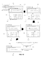
- FIG. 1 conceptually illustrates a process that some embodiments use to generate a flow with zero or more wildcard fields.
- FIG. 2 illustrates an example of a switching element that dynamically generates a flow with a wildcard field.
- FIG. 3 shows an example how the switching element uses the flow with the wildcard field to process subsequent packets.
- FIG. 4 conceptually illustrates an architectural diagram of a software-switching element of some embodiments.
- FIG. 5 conceptually illustrates several processes, which show the interactions between several switch components when generate and cache flow with zero or more wildcard fields.
- FIG. 6 illustrates an example of a switching element that finds a matching flow that is stored in a cache.
- FIG. 7 illustrates an example of transferring control to a switch daemon when there is no matching flow stored in the cache.
- FIG. 8 illustrates an example of the switch daemon generating a flow to store in the cache.
- FIG. 9 shows an example of un-wildcarding a match field because it was compared against a header value.
- FIG. 10 illustrates an example of iterating through multiple flows and un-wildcarding multiple match fields.
- FIG. 11 provides an illustrative example of a resubmit operation.
- FIG. 12 illustrates an example of the switching element un-wildcarding a match field that is not explicitly specified in a flow from a flow table.
- FIG. 13 illustrates an example of the switching element un-wildcards the corresponding MAC address fields based on an action associated with a flow.
- FIG. 14 provides an illustrative example of how the switching element utilizes a number of different components to generate the flow entry.
- FIG. 15 illustrates an example of how the datapath flow generator generates a flow by interfacing with different components.
- FIG. 16 conceptually illustrates a process that some embodiments perform to dynamically generate a new flow with zero or more wildcard fields.
- FIG. 17 illustrates several examples of flows that are stored in a datapath cache.
- FIG. 18 conceptually illustrates an electronic system with which some embodiments of the invention are implemented.
- Some embodiments of the invention provide a switching element that receives a packet and processes the packet by dynamically generating a flow entry with a set of wildcard fields.
- the switching element then caches the flow entry and processes any subsequent packets that have header values that match the flow entry's non-wildcard match fields.
- each subsequent packet does not have to have header values that match all of the flow entry's match fields but only its non-wildcard fields.
- the switching element does not have to generate a new flow entry when it receives a similar packet with one or more different header values.
- the switching element can continue to process such a similar packet as long as its header values match the non-wildcard fields.
- FIG. 1 conceptually illustrates a process 100 that some embodiments use to process packets.
- the process 100 illustrates an example of dynamically generating a flow with zero or more wildcard fields.
- the process 100 is performed by a switching element.
- the process 100 begins when it receives (at 105 ) a packet.
- the process 100 determines (at 110 ) whether there is a flow entry stored in the cache that can process the packet. In particular, it determines whether there is a flow entry in which all of its non-wildcard fields match the corresponding header values. If a matching flow entry is found, the process 100 selects (at 115 ) the flow entry.
- the process 100 then performs (at 120 ) a set of actions on the packet according to the selected flow entry.
- the process 100 dynamically generates a new flow entry.
- the process 100 initializes (at 125 ) some or all match as wildcard fields.
- the process 100 then generates (at 130 ) a new flow entry by un-wildcarding each match field that was consulted or examined when generating the flow entry. That is, it un-wildcards each match field that it cared about (e.g., looked at) during the generation of the flow entry.
- the process 100 of some embodiments generates a flow entry with wildcard fields based on one or more flows in a set of one or more flow tables.
- the process 100 may select a flow from a flow table and un-wildcards each match field that is compared against a packet header value.
- the match field is un-wildcarded regardless of whether there was a match between the match field and the header value.
- the process 100 may iteratively select the next flow in the flow table until a matching flow is found. If a matching flow is found, it then generates a flow entry with zero or more wildcard fields, depending on the number of remaining wildcard match fields. In some cases, the process 100 may recirculate to find one or more other matching flows to generate one consolidated flow entry for multiple flows from one or more flow tables.
- the process 100 uses one of several different classification algorithms to find a matching flow.
- classification algorithms include a tuple space search algorithm, a staged lookup algorithm, and a decision tree algorithm. These algorithms will be described below in sub-section III.C below.
- the process 100 of some embodiments un-wildcards match fields based on an action associated with a matching flow.
- the process 100 of some embodiments can be configured to do normal L 2 processing.
- the process 100 may use a media access control address (MAC) learning algorithm to derive an output port for a given packet based on a set of one or more packet header values.
- the process 100 can use the algorithm to identify a MAC address of a machine (e.g., a virtual machine) that is connected to its port or attached to its virtual interface.
- the process 100 can then compare the MAC address to the header's destination Ethernet address and specify an output port if the addresses matches one another. Since the destination MAC address has been looked at, the process 100 can then un-wildcards the corresponding match field when generating the wildcard flow.
- the process 100 upon generating the flow entry, the process 100 then stores (at 135 ) the flow entry in the cache.
- the process 100 caches the flow entry so that it can process 100 any subsequent packets with header values that match all of the flow's non-wildcard fields.
- the process 100 performs (at 140 ) the new flow entry's associated set of actions of the received packet.
- the process 100 then waits (at 145 ) for additional packets. If there is another packet, the process 100 returns to 105 , which is described above. Otherwise, the process 100 then ends.
- Some embodiments perform variations on the process 100 .
- the specific operations of the process 100 may not be performed in the exact order shown and described.
- the specific operations may not be performed in one continuous series of operations, and different specific operations may be performed in different embodiments.
- FIG. 2 illustrates an example of dynamically generating a wildcard flow. Specifically, this figure shows a switching element 205 that examines a flow entry in a flow table and generates a cache flow entry with at least one wildcard field. This example is shown in terms of five stages of operations 245 - 265 of the switching element.
- the switching element 205 includes a datapath flow generator 210 and a datapath manager 220 .
- the switching element 205 forwards data (e.g., data frames, packets, etc.) from one network node (e.g., machine) to one or more other network nodes.
- the switching element 205 can receive packets and can process those packets according to a set of flow entries in one or more flow tables (e.g., the flow table 215 ).
- the switching element 205 of some embodiments is a software or virtual switch.
- a software is formed by storing its flow table(s) and logic in the memory of a standalone device (e.g., a standalone computer), while in other embodiments, it is formed by storing its flow table(s) and logic in the memory of a device (e.g., a computer) that also executes a hypervisor and one or more virtual machines on top of that hypervisor.
- the datapath flow generator 210 is a component of the switching element 205 that makes switching decisions.
- the datapath manager 220 receives the switching decisions, caches them, and uses them to process packets. For instance, when a packet comes in, the datapath manager 220 first checks the datapath cache 225 to find a matching flow entry. If no matching entry is found, the control is shifted to the datapath flow generator 210 . The datapath flow generator 210 then examines a flow table (e.g., the flow table 215 ) to generate a flow to push down to the datapath cache 225 . In this manner, when any subsequent packet is received, the datapath manager 220 can quickly process the packet using the cached flow entry. The datapath manager 220 provides a fast path to process each packet. However, the switching decisions are ultimately made through the datapath flow generator 210 , in some embodiments.
- a flow table e.g., the flow table 215
- the process of determining what to do when there is a missed in the cache can be an expensive operation. The process must be performed each time there is a miss in the cache.
- the switching element 205 must perform a number of different tasks to generate a flow entry to store in the datapath cache 225 .
- the datapath flow generator 210 must iterate through one or more flow tables to find a matching flow entry. This can entail dynamically generating a flow based on a default rule if no matching table entry is found. For instance, the switching element can be configured to do normal L 2 and/or L 3 processing for any packet without a matching flow entry.
- the generation of a flow entry to store in the cache can also entail performing a number of resubmits, and deriving or learning output ports, etc.
- the switching element 205 of some embodiments supports flows with wildcards instead of only exact match flows. In particular, it generates a flow with one or more wildcards and caches that flow. This flow is also referred to as a megaflow because it allows packets that have different wildcard values to be quickly processes. In other words, this caching now collapses similar flows into one userspace “megaflow” that makes many flow misses a cache lookup instead of a full translation (e.g., through the datapath flow generator 210 ).
- the first stage 245 illustrates the switching element 205 receiving a packet 230 .
- the switching element 205 is associated with the flow table 215 .
- the flow table 215 includes only one flow 235 . However, one of ordinary skill in the understand that the table can include many more flows.
- the flow 235 in some embodiments is a table entry that is used to match and process packets. It includes a set of match fields to match packets and one or more actions to perform on matching packets.
- the match fields are ingress port and Ethernet destination address (e.g., destination MAC addresses).
- the action is shown as a number two. This number represents an output port. Accordingly, the flow 235 provides a rule that states that all packets received through ingress port one and that has the matching Ethernet destination address should be output to port two.
- the flow entry 235 can include other variables, such priority and timeout values.
- the priority value identifies the matching precedence of a flow.
- the flow table 215 can include multiple entries that can handle a same packet.
- the switching element iterates through flow entries base on the priority value. The switching element might examine a flow entry with a higher priority value before a lower one. In this way, a flow entry with a higher value will match before a lower one. The first match can then be used to generate a cache flow entry. So, typically, the matching flow with the highest priority is used process a packet, but this may not be true in all cases. As mentioned above, the switch element might re-search the same flow table to find one or more other flows.
- the switching element might consolidate the flows into one cache flow entry.
- the switching element might perform multiple sets of action or just one set of action (e.g., the matching flow with the highest priority value).
- the timeout value represents how long the flow stays in the flow table 215 before it expires. This can be an idle timeout (e.g., if it is inactive) or even a hard timeout (e.g., regardless of its activity).
- the first stage 245 also illustrates the packet 230 that is sent to the switching element.
- packet is used here as well as throughout this application to refer to a collection of bits in a particular format sent across a network.
- packet may be used herein to refer to various formatted collections of bits that may be sent across a network, such as Ethernet frames, TCP segments, UDP datagrams, IP packets, etc.
- the packet is a unit of data that comprises header and user data.
- the header of a packet includes control information that is necessary for the delivery network to deliver the packets from the node that transmits the data packets to the node to which the packets are to be delivered.
- the user data of the packet is data that is to be delivered from one node to another.
- the user data is also called a payload.
- a data packet may include headers of one or more communication protocols. When a data packet includes more than one header, the outer-most header is followed by other headers. The innermost header is usually the last header of the headers before the payload of the packet.
- the network For the network that implements the protocol of the outer-most header of a packet, the network considers only the outer-most header of the packet as the header and the other headers and the user data of the packet are together considered as the payload of the packet.
- the packet 230 is shown with only two header values, namely Ethernet and IP destination addresses. However, a typical packet contains more header values.
- the switching element 205 receives the packet 230 .
- the second stage 250 shows that datapath manager 220 looks for a matching flow that is stored in the datapath cache 225 .
- the datapath cache 225 provides a fast path to process incoming packet because it does not involve any translation by the datapath flow generator 210 .
- the transferring entails sending the packet 230 to the datapath flow generator 210 .
- the third stage 255 illustrates the datapath flow generator 210 dynamically generating a flow entry 240 with at least one wildcard field.
- the datapath flow generator of some embodiments initially wildcards some or all match fields.
- the datapath flow generator 210 selects a flow from the flow table and un-wildcards each match field that it consults or examines. This can include comparing match field and header values, and deriving or learning output ports.
- the datapath flow generator 210 has specified some or all of the match fields to be wildcard fields. That is, some or all of the match fields has been initialized to be wildcard fields, including destination Ethernet address field and IP destination address field.
- the datapath flow generator 210 has also selected the flow entry 235 from the flow table 215 to determine if it is a match for the packet 230 . In making this determination, the datapath flow generator 210 has compared the ingress port of the flow entry 235 with the ingress port at which the packet 230 was received. The datapath flow generator 210 has also compared the destination Ethernet addresses match field against the corresponding header field.
- the datapath flow generator has also specified the destination Ethernet address as a non-wildcard field. However, the destination IP match field remains a wildcard field. This is conceptually shown by the asterisk symbol in the cache flow entry 240 .
- the datapath flow generator 210 has generated the cache entry 240 based on the matching flow 235 .
- the fourth stage 260 illustrates that the flow entry 240 has been pushed down and stored in the datapath cache 225 .
- the cached entry 240 includes an ingress port value, Ethernet destination address value, IP destination address value, and an action value.
- IP address is shown, that field has been specified as a wildcard field.
- the slash mark followed by the asterisk symbol indicates that the entire field has completely been wildcarded. This field has been wildcarded because it was not consulted when generating the flow entry 240 .
- the cached flow entry 240 is also different from the flow 235 from the flow table 215 .
- the cache flow entry does not have a priority value. This is because the datapath cache 240 does not store multiple flows that can match a same packet. In other words, the datapath cache stores only one flow that can match a given packet, instead of multiple entries. Therefore, there are no resubmit operations with the datapath cache, in some such embodiments.
- the flow entry 240 of some embodiments is associated with a priority value.
- the datapath manager 220 may perform one or more resubmit operations operation to find any other matching flows from the datapath cache.
- the fifth stage 260 illustrates the switching element 205 processing the packet 230 .
- the cache entry 240 specifies that any packet that is received at ingress port one and has an Ethernet destination address “A” should be output to port two.
- the IP destination address match field has been wildcarded so that field can have any different value.
- the datapath manager 220 outputs the packet 230 through port two.
- the switching element 205 dynamically generates a flow 240 with at least one wild card field.
- this flow is also referred to as a “megaflow” because it allows packets that have different wildcard values to be quickly processed.
- This caching technique collapses similar into flows into one userspace megaflow that makes many flow misses a cache lookup instead of a full translation.
- FIG. 3 shows an example how the switching element 205 uses the flow entry 240 to process subsequent packets 305 and 310 .
- this figure illustrates the switching element 205 at time one when it receives one subsequent packet 305 and at time two when it receives another subsequent packet 310 .
- the switching element 205 receives the packet 305 .
- the datapath manager 220 receives the packet and parses it to extract or strip its header values.
- the datapath manager 220 also identifies the ingress port through which the packet 305 was received.
- the datapath manger 220 selects the flow entry 240 from the datapath cache 225 and compares the identified ingress port value with the value from the flow entry.
- the datapath manager compares the non-wildcard match field value (i.e., destination Ethernet address field) to the corresponding header field value. As those two values match, the datapath manager performs the associated action, which is to output the packet to port two.
- the datapath manager 220 ignores the IP destination match field from the flow entry 240 because it has been wildcarded. In this case, even if the IP destination address match field has not been wildcarded, the packet would have been output to port two. This is because the IP destination address values from the flow entry and the packet header match one another.
- the switching element 205 receives another subsequent packet 310 . Similar to time one, the datapath manager 220 receives the packet and parses it to extract or strip its header values. The datapath manager also identifies the ingress port through which the packet was received. The datapath manger selects the cache entry 240 and compares the ingress port and the non-wildcard match field (i.e., destination Ethernet address field) to the header fields. As those two values match, the datapath manager performs the associated action, which is to output the packet to port two.
- the non-wildcard match field i.e., destination Ethernet address field
- the destination IP address fields of the flow entry 240 and the packet's header do not match. Therefore, there would have been a miss in the datapath cache 225 , and the packet processing would have to be shifted to the datapath flow generator 210 . As stated above, the process of determining what to do with a flow when it is missed in the cache can be an expensive operation.
- the datapath flow generator 205 must perform a number of different tasks to generate a cache flow entry, such as iterating through flows in the flow table 215 to find a matching flow and/or deriving match field values. At time two, those tasks do not have to be performed. This is because the destination IP address match field has been wildcarded and the packet 310 is processed regardless of the mismatch in the field values. Accordingly, by caching the flow with the wildcard field, the switching element avoids having to do another translation to cache another flow. Such generation of wildcard flows can provide significant flow setup performance, especially when the switching element is able to wildcard many flows.
- Section I describes several an example software-switching element that implements some embodiments of the invention.
- Section II then describes a more detailed example of how the switching element processes packets.
- Section III describes various examples of generating flows with zero or more wildcard fields.
- Section IV describes an electronic system for implementing some embodiments of the invention.
- the switching element of some embodiments receives a packet and processes the packet by dynamically generating a flow entry with a set of wildcard fields. The switching element then stores that flow entry in a cache and processes any subsequent packets that have header values that match the flow entry's non-wildcard match fields.
- the switching element is a software or virtual switch. An example of such a software switch will not be described by reference to FIG. 4 .
- FIG. 4 conceptually illustrates an architectural diagram of a software-switching element 405 of some embodiments that is implemented in a host 400 .
- the software-switching element 405 operates on a virtual machine (VM) 495 and includes several components. These components includes an Open vSwitch (OVS) kernel module 420 , which runs in the kernel of the VM 455 , and an OVS daemon 440 and an OVS database server 445 , which run in the userspace 450 of the VM 495 .
- OVS Open vSwitch
- the host 400 includes hardware 470 , hypervisor 465 , and VMs 402 and 404 .
- the hardware 470 may include typical computer hardware, such as processing units, volatile memory (e.g., random access memory (RAM)), nonvolatile memory (e.g., hard disc drives, optical discs, etc.), network adapters, video adapters, or any other type of computer hardware.
- the hardware 470 includes NICs 485 and 490 , which are typical network interface controllers for connecting a computing device to a network.
- the hypervisor 465 is a software abstraction layer that runs on top of the hardware 470 and runs below any operation system.
- the hypervisor 465 handles various management tasks, such as memory management, processor scheduling, or any other operations for controlling the execution of the VMs 402 and 404 .
- the hypervisor 465 communicates with the VM 495 to achieve various operations (e.g., setting priorities).
- the hypervisor 465 is one type of hypervisor (Xen or KVM hypervisor) while, in other embodiments, the hypervisor 465 may be any other type of hypervisor for providing hardware virtualization of the hardware 470 on the host 400 .
- the hypervisor 465 includes device drivers 475 and 480 for the NICs 485 and 490 , respectively.
- the device drivers 475 and 480 allow an operating system to interact with the hardware of the host 400 .
- VMs 402 and 404 are virtual machines running on the hypervisor 465 . As such, the VMs 402 and 404 run any number of different operating systems. Examples of such operations systems include Linux, Solaris, FreeBSD, or any other type of UNIX based operating system. Other examples include Windows based operating systems as well.
- the VM 495 is a unique virtual machine, which includes a modified Linux kernel, running on the hypervisor 465 .
- the VM 495 may be referred to as domain 0 or dom 0 in some embodiments.
- the VM 495 of such embodiments is responsible for managing and controlling other VMs running on the hypervisor 465 (e.g., VMs 490 and 495 ).
- the VM 495 may have special rights to access the hardware 470 of the host 400 .
- other VMs running on the hypervisor 465 interact with the VM 495 in order to access the hardware 470 .
- the VM 495 may be responsible for starting and stopping VMs on the hypervisor 465 .
- the VM 495 may perform other functions for managing and controlling the VMs running on the hypervisor 465 .
- Some embodiments of the VM 495 may include several daemons (e.g., Linux daemons) for supporting the management and control of other VMs running on the hypervisor 465 . Since the VM 495 of some embodiments is manages and controls other VMs running on the hypervisor 465 , the VM 495 may be required to run on the hypervisor 465 before any other VM is run on the hypervisor 465 .
- daemons e.g., Linux daemons
- the VM 495 includes a kernel 455 and a userspace 450 .
- the kernel is the most basic component of an operating system that runs on a separate memory space and is responsible for managing system resources (e.g., communication between hardware and software resources).
- the userspace is a memory space where all user mode applications may run.
- the userspace 450 of the VM 495 includes the OVS daemon 440 and the OVS database server 445 .
- Other applications may be included in the userspace of the VM 495 as well.
- the OVS daemon 440 is an application that runs in the background of the userspace of the VM 495 .
- the OVS daemon 440 of some embodiments receives switch configuration from the network controller 406 (in a network controller cluster) and the OVS database server 445 .
- the management information includes bridge information, and the switch configuration includes various flows. These flows are stored in the flow table 415 . Accordingly, the software-switching element 405 may be referred to as a managed forwarding element.
- the OVS daemon 440 communicates with the network controller using OpenFlow Protocol.
- the OVS database server 445 communicates with the network controller 406 and the OVS daemon 440 through a database communication protocol (e.g., OVS database protocol).
- the database protocol of some embodiments is a JavaScript Object Notation (JSON) remote procedure call (RPC) based protocol.
- JSON JavaScript Object Notation
- RPC remote procedure call
- the OVS database server 445 is also an application that runs in the background of the userspace of the VM 495 .
- the OVS database server 445 of some embodiments communicates with the network controller 406 in order to configure the OVS switching element (e.g., the OVS daemon 440 and/or the OVS kernel module 420 ).
- the OVS database server 445 receives management information from the network controller 406 for configuring bridges, ingress ports, egress ports, QoS configurations for ports, etc., and stores the information in a set of databases.
- the kernel 455 includes the OVS kernel module 420 .
- This module processes and routes network data (e.g., packets) between VMs running on the host 400 and network hosts external to the host (i.e., network data received through the NICs 485 and 490 ).
- network data e.g., packets
- the OVS kernel module 420 of some embodiments routes packets between VMs running on the host 400 and network hosts external to the host 400 couple the OVS kernel module 420 through a bridge 408 .
- the bridge 408 manages a set of rules (e.g., flow entries) that specify operations for processing and forwarding packets.
- the bridge 408 communicates with the OVS daemon 440 in order to process and forward packets that the bridge 408 receives. For instance, the bridge 408 receives commands, from the network controller 406 via the OVS daemon 445 , related to processing and forwarding of packets.
- the bridge 408 includes a packet processor 430 , a classifier 460 , and an action processor 435 .
- the packet processor 430 receives a packet and parses the packet to strip header values.
- the packet processor 430 can perform a number of different operations.
- the packet processor 430 is a network stack that is associated with various network layers to differently process different types of data that it receives. Irrespective of all the different operations that it can perform, the packet processor 430 passes the header values to the classifier 460 .
- the classifier 460 accesses the datapath cache 425 to find matching flows for different packets.
- the datapath cache 425 contains any recently used flows. The flows may be fully specified, or may contain one or more match fields that are wildcarded.
- the classifier 460 receives the header values, it tries to find a flow or rule installed in the datapath cache 425 . If it does not find one, then the control is shifted to the OVS Daemon 440 .
- One main distinction between the fast path cache 425 and the set of flow tables 415 is that there is at most only one matching flow entry in the fast path cache 425 .
- the action processor 435 receives the packet and performs a set of action that is associated with the matching flow.
- the action processor 435 of some embodiment also receives, from the OVS daemon 440 , a packet and a set of instructions to perform on the packet. For instance, when there is no matching flow in the datapath cache 425 , the packet is sent to the OVS daemon 440 .
- the OVS daemon 440 may generate a flow and install that flow in the datapath cache 425 .
- the OVS daemon 440 might also send the packet to the action processor 435 with the set of actions to perform on that packet.
- the OVS daemon 440 of some embodiments includes a datapath flow generator.
- the datapath flow generator 440 is a component of the software switching element 405 that makes switching decisions. Each time there is a miss in the datapath cache 425 , the datapath flow generator 440 generates a new flow to install in the cache.
- the datapath flow generator works in conjunction with its own separate classifier (not shown) to find one or more matching flows from a set of one or more flow table 415 .
- the OVS daemon's classifier can perform one or more resubmits. That is, a packet can go through the daemon's classifier multiple times to find several matching flows from one or more flow table 415 .
- the datapath flow generator 410 When multiple matching flows are found, the datapath flow generator 410 of some embodiments generates one consolidated flow entry to store in the datapath cache 425 .
- the switching element allows flows with wildcards to be specified in the flow table 415 . However, different from the datapath flows, these flows are not dynamically generated on the fly (e.g., in response to a miss in the datapath).
- the architecture is an example architecture and that different embodiments can include different sets of components.
- the naming of the various components is arbitrary and can change from one implementation to another.
- the architecture shows two different layers (e.g., the kernel layer and the userspace layer) performing various operations. In some embodiments, these operations occur at just one layer (e.g., at the userspace layer) or are further split into other layers.
- FIG. 5 conceptually illustrates several processes 500 A-D, which show the interactions between such components to generate and cache a flow with zero or more wildcard fields.
- the processes 500 A-D will be described by reference to FIGS. 6-9 .
- the process 500 A shows example operations performed by a kernel module when it receives a packet.
- the process 500 A begins when it receives (at 502 ) a packet.
- the process 500 A then performs a lookup operation on the cache to identify a matching flow entry for the packet. Specifically, the process 500 A iteratively selects (at 504 ) a flow entry that is cached to find one flow entry that matches each of the entry's non-wildcard fields. If a matching entry is found, the process 500 A selects (at 508 ) the flow entry.
- the process 500 A then performs (at 510 ) a set of actions that is specified by that flow entry. If no matching entry is found, the process 500 A proceeds to 506 , which is described below.
- the packet may be sent the OVS daemon (e.g., the userspace) even if there is a match in the kernel. This is because some packets are too complicated for the kernel to handle.
- a “userspace” action is installed in the datapath cache (e.g., the kernel flow table), which specifies pushing all packets to the OVS daemon.
- FIG. 6 illustrates an example of a switching element 405 that finds a match in a datapath cache 425 .
- Two operational stages 605 and 610 of the switching element's kernel module 420 are shown in this figure.
- the bridge 408 has been configured, and two flow entries 620 and 625 are stored in the datapath cache 425 .
- each of the flow entries 620 and 625 has at least one wildcard match field. These entries might have been pushed down earlier by the OVS daemon (not shown) based on two previously received packets.
- the first stage 605 illustrates the kernel module 420 receiving a packet 615 .
- the packet 615 is received by the packet processor 430 through the bridge 408 .
- the packet includes a number of header fields.
- the header fields are specified as field 1 through field N.
- the header field 1 has a value of “A”
- field 2 has a value of “B”
- field N has a value of “C”.
- the second stage 610 illustrates an example of processing the packet after finding a matching flow in the datapath cache 425 .
- the packet processor 430 first strips the headers off the packet 615 .
- the classifier 460 selects the first flow entry 620 and compares its non-wildcard match field values against the corresponding header values.
- the first flow entry 620 is a match for the packet 615 .
- the action processor 435 performs the flow entry's associated set of actions on the packet 615 , which is to output the packet to output port three.
- FIG. 7 illustrates an example of transferring control to the OVS daemon 440 when there is a miss in the datapath cache 425 .
- the first stage 705 illustrates the kernel module 420 receiving a packet 715 .
- the packet 715 is received by the packet processor 430 through the bridge 408 .
- the packet includes a number of header fields.
- the header field 1 has a value of “E”, field 2 has a value of “F”, and field N has a value of “G”.
- the second stage 710 illustrates an example of how control is shifted to the OVS daemon when there is a miss in the datapath cache 425 .
- the packet processor 430 first parses the packet to strip the headers from the packet 715 .
- the classifier 460 selects the first flow entry 620 and compares its non-wildcard match field values against the corresponding header values.
- the non-wildcard fields of the first flow entry 620 do not match the corresponding header values.
- the classifier 460 selects the second flow entry 625 and compares its non-wildcard match field values against the corresponding header values.
- the second flow entry 625 is also not a match for the packet 715 .
- the classifier 460 sends the packet to the OVS daemon 440 .
- Process 500 B shows several example operations that can occur at the OVS daemon when it receives a packet from the kernel module. As shown, the process 500 B begins when it receives (at 512 ) the packet from the kernel module. The process then dynamically generates (at 514 ) a new flow entry with zero or more wildcard fields.
- FIG. 8 illustrates an example of the OVS daemon 440 generating a flow and sending it to the kernel module 420 .
- Two operational stages 805 and 810 are illustrated in this figure. These stages 0805 and 810 are a continuation of the stages 705 and 710 shown in FIG. 7 .
- the OVS daemon 440 includes a datapath flow generator 410 to dynamically generate a new flow to store in the datapath cache 425 . Similar to the kernel module 420 , the datapath flow generator 410 is associated with a classifier 720 . This classifier 720 is used to find a matching flow from one or more flow tables 415 .
- the OVS daemon's classifier 415 can perform one or more resubmits. That is, a packet can go through the daemon's classifier multiple times to find several matching flows from one or more flow tables (e.g., the flow table 415 ). For instance, even if a matching flow is found, the flow's associated action may specify a resubmit operation. The resubmit operation re-searches the same flow table (or another specified flow table) and creates a flow entry that specifies additional actions found, if any, in addition to any other actions in the original matching flow. In some embodiments, the datapath flow generator specifies performing only a set of actions associated with the flow from the flow table with the highest priority value.
- the first stage 805 illustrates the OVS daemon 440 after it has received the packet 715 from the kernel module 420 .
- This stage also shows the OVS daemon 440 sending a new flow 820 to the kernel module 420 .
- the datapath flow generator 410 has generated the new flow 820 .
- the datapath flow generator 410 of some embodiments initially wildcards some or all match fields.
- the classifier 410 Upon the datapath flow generator 410 receiving the packet, it calls the classifier 410 to iterate through flows in the flow table 415 .
- the classifier 410 selects a flow entry from the flow table and un-wildcards each match field that was compared against the packet's header field.
- the data flow generator 440 of some embodiments generates a flow entry by deriving or learning output ports.
- the data flow generator 440 may consult one or more match field values, un-wildcard the match fields, and specify those match field values as non-wildcard field values in the flow entry.
- the data flow generator 440 of some embodiments generates a flow entry by communicating with one or more different forwarding decision modules 725 , such as a MAC learning module. This MAC learning module may learn MAC addresses in a typical manner that layer 2 switches learn MAC addresses.
- the MAC learning module may flood all of the ports of the bridge 408 and record the MAC address of the packet that responds to the flood.
- the process 500 B sends (at 516 ) instructions to the kernel module to cache the flow entry.
- the process then sends (at 518 ) the packet to the kernel module with instructions to perform a set of actions on the packet.
- the process 500 B then ends.
- the process 500 C shows operations performed by the kernel module after the OVS daemon has generated a new flow entry and sent instructions to install the new flow entry in the cache. As shown, the process 500 C begins when it receives (at 520 ) the instructions from the OVS daemon to cache the new flow entry. The process 500 C then caches (at 522 ) the flow entry. The process 500 C then ends.
- the process 500 D shows operations performed by the kernel module after the OVS daemon has generated a new flow entry and sent the packet to the kernel module with instructions to perform a set of actions on the packet. As shown, the process 500 D begins when it receives (at 524 ) the packet with instructions to perform a set of actions on the packet. The process 500 D then performs (at 526 ) the set of action on the packet. The process 500 D then ends.
- the second stage 810 of FIG. 8 illustrates the kernel module 420 after receiving the flow entry 820 .
- the classifier 460 has received the flow entry 820 through the bridge 408 .
- the classifier 460 has installed the flow entry 820 in the datapath cache 425 .
- the third stages 815 illustrates that the flow entry 820 includes a number of wildcard match fields.
- the packet is then received at the action processor from the OVS daemon.
- the packet is received with instructions to perform a set of actions.
- the set of actions may be the same as the one associated with the cached flow entry 820 .
- the action processor 435 performs the flow entry's associated action on the packet 715 , which is to output the packet to output port five.
- the switching element of some embodiments dynamically generates flows with wildcards.
- the switching element initially wildcards some of all of match fields and generates a new flow entry by un-wildcarding each match field that was consulted to generate the flow entry.
- the switching element of some embodiments generates a flow by un-wildcarding each match field that was compared against a header value.
- FIG. 9 shows an example of un-wildcarding a match field because it was compared against a header value.
- Four operational stages 905 - 920 of the switching element 405 are shown in the figure.
- the switching element 405 includes the datapath flow generator 410 , which was described above by reference to FIG. 4 .
- Stage 905 begins when there is a miss in the datapath cache.
- the packet processing is shifted from the kernel module to the OVS daemon 440 .
- the kernel module sends the packet 945 to the OVS daemon 440 .
- the daemon's datapath flow generator 410 receives the packet 410 and generates a new flow entry to store in the datapath cache.
- the first stage 905 illustrates the datapath flow generator 410 receiving the packet 945 .
- the packet 945 has the following header field values: Ethernet source value of “A”, Ethernet destination value of “B”, and field N value of “C”.
- the datapath flow generator 410 selects a first flow or rule 930 from the flow table 415 . If there are multiple flows, the flow may be sorted by priority values (e.g., from highest to lowest).
- the second stage 910 illustrates that the datapath flow generator 410 initializing a group of match field values as wildcards.
- the datapath flow generator 410 of some embodiments generates a flow entry 940 by keeping track of the data value of each match field, and a mask associated with that field. If a field is masked, that match field value was not consulted (e.g., compared against a corresponding header filed value) to generate the flow entry. As such, a masked field represents a wildcard field. In some embodiments, the entire match field may be masked or wildcarded. Alternatively or conjunctively, the switching element 405 of some embodiments allows masking or wildcarding at the sub-value level.
- the switching element supports masking portion of the match field (e.g., a portion of the IP address field) rather than the entire match field value.
- a mask value of zero indicates that the match field has been completely wildcarded, and a mask value of one indicates that the match field was consulted.
- the third stage 915 illustrates the datapath flow generator 410 generating the cache flow entry 940 based on the selected flow 930 and the packet header values. Specifically, the datapath flow generator 410 has selected the flow 930 and compared the flow's Ethernet destination value with the corresponding header value. As the Ethernet destination match field was compared against a header field value, the datapath flow generator 410 has unmasked the match field. This is shown in the third stage 915 with the zero value being replaced by the one value in the cache flow entry 940 , namely from the mask of the Ethernet destination address match field.
- the third stage 915 also illustrates that the datapath flow generator 410 has found a matching flow for the packet. This is because the flow's only match field matches the corresponding header value.
- the fourth stage 920 shows the OVS daemon 440 sending the cache flow entry 940 to the kernel module.
- the datapath flow generator 410 has associated the action from the flow 930 with the cache flow entry 940 .
- the cache flow entry 940 reads that Ethernet source address has a value of “A”, Ethernet destination address has a value of “B”, and field N has a value of “C”. Although the Ethernet source address and Field N are associated with values, the zero value after the slash mark indicates that each of these match fields is completely masked or wildcarded.
- the cache flow entry 940 is associated with an action, which is to drop any packet that has an Ethernet destination address value of “B”.
- FIG. 10 illustrates an example of iterating through multiple flows to find a match. Specifically, this figure illustrates that a wildcard match field is specified to be a non-wildcard field when it is compared against a corresponding header value, regardless of whether there was a match or a mismatch. This figure is similar to the previous figure, except that the flow 930 is the second flow in the flow table 415 .
- the first stage 1005 illustrates the datapath flow generator 410 receiving the packet 945 .
- the packet has the following header field values, Ethernet source value of “A”, Ethernet destination value of “B”, and field N value of “C”.
- the datapath flow generator 410 selects a first flow or rule 1030 from the flow table 415 .
- the flow 1030 has instructions to output every packet with an Ethernet source value of “D” to output port two.
- the second stage 1010 illustrates the datapath flow generator 410 building the cache flow entry 1025 based on the selected flow 1030 and the packet header values.
- the field values are extracted from the packet header and each value is associated with a mask that identifies whether the value is associated with a wildcard match field.
- the datapath flow generator has selected the flow 1030 with the highest priority value and compared the flow's Ethernet source value with the corresponding header value. As the Ethernet source match field was compared against a header field value, the datapath flow generator 410 has unmasked the match field. This is shown in the second stage 1010 with the zero value being replaced with the one value in the cache flow entry 1025 , namely from the mask of the Ethernet source address match field.
- the datapath flow generator has selected the flow 930 with the next highest priority value. Specifically, the datapath flow generator 410 has selected the flow 930 and compared the flow's Ethernet destination value with the corresponding header value. As the Ethernet destination match field was compared against a header field value, the datapath flow generator 410 has unmasked the match field. This is shown in the third stage 1015 with the zero value being replaced with the one value in the cache flow entry 1025 , namely from the mask of the Ethernet destination address match field.
- the third stage 1015 also illustrates that the datapath flow generator 410 has found a matching flow for the packet. This is because the second flow's only match field matches the corresponding header value.
- the fourth stage 1020 shows the OVS daemon 440 sending the cache flow entry 1025 to the kernel module.
- the datapath flow generator 410 has associated the action from the flow 930 with the cache flow entry 1025 .
- the cache flow entry 1025 reads that Ethernet source address has a value of “A”, Ethernet destination address has a value of “B”, field N has a value of “C”. Although Field N is associated with a value, the zero value after the slash mark indicates that the match field is completely masked or wildcarded.
- the cache flow entry 1025 is associated with an action, which is to drop any packet that has an Ethernet destination address value of “B”.
- FIG. 11 provides an illustrative example of generating a flow entry based on multiple matching flows from a flow table.
- Four operational stages 1105 - 1120 are illustrated in this figure. These stages 1105 - 1120 are similar to the previous figure, except that the first flow from the flow table is a match for packet. The first flow is associated with a resubmit action.
- the first stage 1105 illustrates the datapath flow generator 410 receiving the packet 945 .
- the second stage 1110 illustrates the datapath flow generator 410 building the cache flow entry 1125 based on the selected flow 1030 and the packet header values. Specifically, the datapath flow generator has selected the flow 1130 (e.g., with the highest priority value) from table zero and compared the flow's Ethernet source value with the corresponding header value. As the Ethernet source match field was compared against a header field value, the datapath flow generator 410 has unmasked the match field. This is shown in the second stage 1110 with the zero value being replaced with the one value in the cache flow entry 1125 , namely from the mask of the Ethernet source address match field.
- the flow 1030 was a match for the packet 945 because their Ethernet sources address values matches one another.
- the flow 1130 is associated with a resubmit operation (e.g., to concatenate multiple flows into one datapath flow).
- the resubmit operation specifies resubmitting into another flow table (i.e., flow table two).
- the datapath flow generator 410 has selected the flow 1135 (e.g., with the highest priority value) from flow table two.
- the datapath flow generator 410 has selected the flow 1135 and compared the flow's Ethernet destination value with the corresponding header value.
- the datapath flow generator 410 has unmasked the match field. This is shown in the third stage 1115 with the zero value being replaced with the one value in the cache flow entry 1125 , namely from the mask of the Ethernet destination address match field.
- the third stage 1115 also illustrates that the datapath flow generator 410 has found a matching flow for the packet. This is because the only match field of the flow 1135 matches the corresponding header value. In this example, all match fields that were specified as wildcards or non-wildcards carries over when there is a resubmit operation. That is, the OVS daemon does not reinitialize all the match fields as wildcards when there is a resubmit. However, the OVS daemon might reinitialize them as wildcards, in some other embodiments.
- the fourth stage 1120 shows the OVS daemon 440 sending the cache flow entry 1125 to the kernel module.
- the datapath flow generator 410 has associated the action from the flow 1135 with the cache flow entry 1125 .
- the cache flow entry 1125 reads that Ethernet source address has a value of “A”, Ethernet destination address has a value of “B”, and field N has a value of “C”. Although Field N is associated with a value, the zero value after the slash mark indicates that the match field is completely masked or wildcarded.
- the cache flow entry 1125 is associated with an action, which is to drop any packet that has an Ethernet destination address value of “B”.
- the OVS daemon finds a matching flow that has a resubmit action.
- the resubmit action specifies performing a resubmit to another flow table.
- the resubmit action can specify a resubmit operation on the same flow table.
- One example way of resubmitting the packet to the same flow table is to modify the packet in some way before the resubmission.
- the action of the initial matching flow could specify changing a matching header value (e.g., the Ethernet source value). This is because if the matching header value remains the same, the same initial flow will once again match the packet.
- a flow in a flow table may have a value for a match field value that requires the datapath flow generator 410 to examine one or more other match fields. For example, when a match field relates to an IP address or an Ethernet address, the datapath flow generator 410 might first consult the Ethertype match field and determine if the corresponding header value matches the match field value. The datapath flow generator may then un-wildcard the Ethertype match field.
- FIG. 12 illustrates an example of the switching element 405 un-wildcarding a match field that is not explicitly specified in a flow 1240 .
- Five operational stages 1205 - 1225 of the switching element 405 are shown in this figure.
- the first stage 1205 illustrates the datapath flow generator 410 receiving a packet 1235 .
- the packet has the following header field values, Ethertype of “0x0800”, IP sources address value of “1.1.1.1”, and IP destination address value of “1.1.1.2”.
- Ethertype of “0x0800” IP sources address value of “1.1.1.1”
- the datapath flow generator 410 selects a first flow or rule 1240 from the flow table 415 .
- the flow 1230 has a rule that states that any packet with an IP sources address of “1.1.1.1” should be output to port two.
- the second stage 1210 illustrates the first comparison was made for a match field that is not explicitly specified in the flow 1240 .
- the first comparison was made to a related field that indicates which protocol is encapsulated in the payload of the packet or frame.
- the header value “0x0800” indicates that the Ethertype is for Internet Protocol version 4 (IPv4).
- IPv4 Internet Protocol version 4
- the comparison of the Ethertype match field provides the datapath flow generator 410 with a quick feedback on whether to compare the match field of the flow 1240 to the corresponding header value. In this case, as the Ethertype value relates to the IP source or destination address, the datapath flow generator 410 unmasks the Ethertype match field and proceeds to stage three 1215 . In cases where the Ethertype values does not relate to IP source or destination address, the datapath flow generator 410 may unmask the Ethertype match field and select another flow to perform the matching.
- the third stage 1215 illustrates comparing a match field associated with the flow 1240 to the corresponding header value.
- the datapath flow generator 410 has selected the flow 1240 and compared the flow's IP source address value with the corresponding header value.
- the datapath flow generator 410 has unmasked the match field. This is shown in the third stage 1215 with the zero being replaced by a one in the cache flow entry 1235 , namely from the mask of the IP source address match field.
- the third stage 1215 also illustrates that the datapath flow generator 410 has found a matching flow for the packet 1230 . This is because the flow's only match field matches the corresponding header value.
- the fifth stage 1225 shows the OVS daemon 440 sending the cache flow entry 1235 to the kernel module. Specifically, the datapath flow generator 410 has associated the action from the flow 1240 with the cache flow entry 1235 .
- the cache flow entry 1235 reads that any packet having the EtherType value of ““0x0800” and IP source address value of “1.1.1.1” should be output to port two.
- the cache flow entry 1235 includes a value for the IP destination address match field. However, the zero value after the slash mark indicates that the IP destination address match field is completely masked or wildcarded.
- the switching element un-wildcards each match field that was compared against a header value to find a matching flow.
- the switching element of some embodiments un-wildcards match fields after it finds the matching flow.
- an action associated with the flow may specify consulting one or more header field values. When those field values are consulted, the switching element of some embodiments un-wildcards the corresponding match fields.
- FIG. 13 illustrates an example of the switching element 405 that examines one or more match fields based on an action of a match rule.
- the flow table includes a rule 1325 that specifies doing normal L 2 /L 3 processing for all packets.
- Four operational stages 1305 - 1320 of the switching element 405 are shown in this figure. This example assumes that the switching element 405 is performing a bonding operation that allows more than one interfaces for a port.
- the first stage 1305 illustrates the datapath flow generator 410 receiving a packet 1330 .
- the packet has the following header field values, Ethernet type of “0x0800”, Ethernet source of “Foo”, Ethernet destination of “Bar”, IP sources address value of “1.1.1.1”, IP destination address value of “1.1.1.2”, and a field N value of “A”.
- the datapath flow generator 410 selects a first flow or rule 1325 from the flow table 415 .
- the second stage 1315 illustrates EtherType value being consulted for the cache flow entry 1335 .
- the datapath flow generator 410 has examined the EtherType value and unmasked the same field.
- the third stage 1315 illustrates IP source address and destination address values being consulted for the cache flow entry 1335 .
- the IP address values are derived from the corresponding packet header values.
- the third stage 1315 also shows that that two IP source and destination match fields are specified to be non-wildcard fields. This is because the switching element has been configured to do normal L 2 /L 3 processing by matching at least these two field values against incoming packets.
- the fourth stage 1320 illustrates Ethernet source address and destination address being consulted to the cache flow entry 1335 .
- the Ethernet address values are derived from the corresponding packet header values.
- the fourth stage 1320 also shows that that the two match fields are specified to be non-wildcard fields as the corresponding masks are removed from the cache flow entry 1335 . This is because the switching element has been configured to do normal L 2 /L 3 processing by matching at least these two additional field values against incoming packets.
- the switching element 405 has associated an action to the cache flow entry 1335 .
- the switching element 405 assigns the action based on results of a learning algorithm.
- the datapath flow generator might have chosen an output port based on the results of the MAC learning algorithm.
- the OVS daemon includes a MAC learning module.
- the MAC learning module of some embodiments identifies, for a given packet, one or more ports to output the packet based on the packet's header field values.
- FIG. 14 provides an illustrative example of how the switching element 405 utilizes a number of different components to generate the flow entry 1335 .
- Three operational stages 1405 - 1415 of the switching element 405 are shown in this figure.
- the datapath flow generator 410 operates in conjunction with a number of modules to dynamically generate a flow entry to cache in a datapath cache. These modules include the classifier 720 , a bonding module 1420 , and a MAC learning module 1425 .
- the cache flow 410 generator may operate in conjunction with a set of other modules 1430 to match and/or derive field values.
- the first stage 1305 illustrates the OVS daemon 440 receiving the packet 1330 .
- the packet is passed to the classifier 720 through the datapath flow generator 410 .
- the classifier 720 derives various field values relating to the packet. This includes (1) the ingress port through which the packet was receives, (2) the EtherType value, (3) the source IP address, and (4) the destination IP address.
- the second stage 1410 also shows that the packet processing operation is then shifted to the bonding module 1420 .
- the third stage 1415 illustrates the bonding module 1420 calling the MAC learning module to associate the cache flow entry with MAC address values.
- the MAC learning module 1430 of some embodiments identifies, for a given packet, one or more ports to output the packet based on the packet's header field values.
- the bonding module 1420 adds the Ethernet source and destination addresses returned by the MAC learning module 1430 to the cache flow entry.
- FIG. 15 illustrates an example of how the datapath flow generator 410 generates a flow by interfacing with different components.
- the components include the classifier 720 , the bonding module 1420 , the MAC learning module 1425 , Bidirectional Forwarding Detection (BFD) module 1505 , and learning action module 1510 .
- the MAC learning module 1425 identifies, for a given packet, one or more ports to output the packet based on the packet's header field values (e.g., the destination Ethernet field value).
- the classifier 720 of some embodiments is called to match certain match fields.
- the bonding module 1420 is called to perform bonding operation that allows more than one interfaces for a port.
- the BFD module 1505 is used to detect whether a packet is a BFD packet. For example, if a packet comes in, the BFD module 1505 may be called to determine whether the packet is a BFD packet or not. This may cause a change in the masking or wildcarding of match fields relating to BFD. If the packet is a BFD, the BFD module 1505 may consume the packet and generation of the cache flow will terminate at that point. Different from the BFD module 1505 , the learn action module 1510 installs a rule in the classifier, which can affect traffic.
- the learn action module 1510 can be used to more abstractly learn MAC addresses. For example, if a packet with a particular Ethernet source address comes in through port 1 , the learn action module 1510 can be used to install a rule that specifies that any packet whose destination MAC address field has the same address should be output to port 1 .
- the datapath flow generator 410 may call any one or more of these modules. One or more of these modules may call another module. Each one of the different modules may be called an arbitrary number of times when generating the flow to store in the cache. As an example, the data flow generator may call the classifier and receive a result; however, depending on the flow, it can call other modules such as the MAC learning module.
- the modules shown in FIG. 15 are example modules. For example, different embodiments can include even more modules, fewer modules, or different combination of modules.
- FIG. 16 conceptually illustrates a process 1600 that some embodiments perform to dynamically generate a new flow with zero or more wildcard fields.
- the process is performed by the switching element's OVS daemon.
- the process 1600 begins when it receives (at 1605 ) a packet (e.g., from the kernel module). The process 1600 then initializes or sets (at 1610 ) all match fields as wildcard match fields. Alternatively, the process 1600 might initialize some but not all match fields as wildcard fields. In addition, the process 1600 might initialize an ingress port field as a wildcard field.
- the ingress port is the port through which the switching element has received the packet.
- the ingress port may be a logical port. In some embodiments, the process never wildcards the ingress port field.
- the process 1600 determines if there any available flows (e.g., in a flow table).
- the process selects a flow from a flow table. If there are no flows, the process might select a rule (e.g., a default rule).
- the switching element can have such one or more rules that specifies performing normal L 2 processing, dropping packet, and/or sending the packet to the network controller.
- the process 1600 selects a flow according to its associated priority value. For example, the process 1600 might iteratively select flows, starting from the one with the highest priority value to the lowest priority value. This is because there might be two flows in a flow table that match a packet but only one matching flow is cached in a datapath cache.
- the process 1600 determines (at 1620 ) whether any one or more match fields have been compared with header values. If so, the process 1600 marks (at 1625 ) each of the one or more match fields as non-wildcard fields. Otherwise, the process determines (at 1630 ) whether the flow is a match for the packet. If the flow is not a match, the process returns to 1615 , which is described above. Otherwise, the process 1600 determines (at 1635 ) whether the action of the matching flow specifies consulting one or more match fields. For example, based on the action, a switching element might consult a destination Ethernet address value of a packet to compare against a MAC address of a virtual machine that is connected to its port. As another example, the process 1600 might check if the packet is a BFD packet. If the process performs such consultation, the process 1600 marks (at 1640 ) the one or more match fields as non-wildcard fields.
- the process 1600 determines (at 1645 ) whether the matching flow is associated with a resubmit operation.
- the resubmit operation is used to concatenate multiple flows into one datapath flow.
- the process might be set up as multiple pipelines the packet goes through (e.g., to do a look-up in the L 2 pipeline, then do a resubmit, and do a look-up in the L 3 pipeline, etc.).
- each wildcard and non-wildcard fields caries over from one hop to the next.
- the process 1600 returns to 1615 , which is described above. If the flow is not associated with such resubmit action, the process 1600 generates (at 1650 ) a new flow entry.
- the process 1600 of some embodiments generates the new flow entry by taking into account each remaining wildcard match fields. That is, the generated flow may include zero or more wildcard fields based on whether any of the wildcarded fields were marked as non-wildcard files (e.g., at operation 1625 and 1640 ).
- the process 1600 sends (at 1655 ) the flow entry to the kernel. The process 1600 then ends.
- Some embodiments perform variations on the process 1600 .
- the specific operations of the process 1600 may not be performed in the exact order shown and described. For example, some embodiments optimize the process through a series of hash table look-ups when matching flows. Accordingly, the specific operations may not be performed in one continuous series of operations, and different specific operations may be performed in different embodiments.
- the datapath flow generator utilizes a “linear search” algorithm to find a matching flow.
- the “linear search” algorithm does not require much memory, but it may be not be very fast.
- the switching element of some embodiments can utilize one of a number of different algorithms when un-wildcarding match fields. Several examples such classification algorithms will now be described in this sub-section.
- the switching element uses a tuple search algorithm to find a matching flow.
- the tuple space search algorithm is a hashed-based search algorithm. It is similar to the “linear search” algorithm. However, instead of linearly traversing through every rule, the tuple space algorithm linearly traverses through different groups of rules that are organized by match fields. In some cases, the tuple space search can be much faster than a “linear search” because it can perform a lookup within a group of rules that have the same wildcard pattern using a hash table.
- the switching element organizes these rules into different groups based on what fields (or partial fields) the rules match on. In this case, there are two groups:
- each rule is placed in a hash table that belongs to a particular group (e.g., group 1 or group 2 ).
- the hash table can have very fast (e.g., nearly instant) lookup.
- the switching element can traverse through each hash table, doing a hash table lookup on each one, and un-wildcarding the fields that the switching element looks at or consults.
- each hash table carries with it the priority of the highest priority rule it contains. Hence, if there is a match in the first hash table, the switching element is programmed to know that the rule has a higher priority value than every other rule in a subsequent table. The switching element can therefore skip the lookup and un-wildcarding in the subsequent hash table.
- the switching element uses a staged lookup algorithm to search for one or more matching flows.
- the staged lookup algorithm is similar to the tuple space algorithm; however, it takes into account the fact that some header fields may change more frequently than others. Based on this fact, it performs a multi-staged search starting with infrequently changing fields, and progressing to frequently changing ones.
- the switching element of some embodiments does not look at all the fields (e.g., in a hash table) at once but first looks at those fields that do not change frequently. If none of those fields matches, the switching element terminates the lookup operation without having to lookup fields that change frequently. For instance, suppose that there is a particular hash table, which looks at the fields, in_port, eth_src, ip_src, and tcp_src.
- the software switching element looks at all those fields irrespective of whether the fields changes frequently or infrequently.
- the lookup is broken into different stages. For instance, in the first stage, the algorithm can look up the in_port in a hash table and get a simple “yes” or “no” as to whether there is a match on the in_port. If the answers “no”, the algorithm can terminate knowing that no further stages match. If the answer is “yes”, the algorithm can proceed to the next stage, which looks up the in_port and eth_src in a separate hash table. If successful, the algorithm may move onto in_port, eth_src, and ip_src.
- the algorithm may look up the full in_port, eth_src, ip_src, and tp_src.
- the algorithm can terminate without looking at the higher layer headers. This is important because the higher layer headers are the ones that are most likely to change from packet to packet and therefore the most problematic when trying to improve performance (e.g., megaflow performance).
- the switching element uses a decision tree algorithm to perform the classification operations.
- the decision tree algorithm entails performing several phases of operations. For example, in the first phase, some fields of the packet header are split up into multiple chunks that are used to index into multiple memories in parallel. Each of the parallel lookups yields an output value. The contents of each memory are chosen so that the result of the lookup is narrower than the index. In subsequent phases, the index into each memory is formed by combining the results of the lookups from earlier phases. In the final phase, there is one result left from the lookup. This is because of the way the memory contents have been pre-computed.
- the decision tree algorithm is also described in the document entitled “Packet Classification on Multiple Fields” by Pankaj Gupta and Nick McKeown. The document was published in October of 1999 and is incorporated herein by reference.
- the switching element of some embodiments does not wildcard a match field if it has to look at a field in the packet header. This same principle applies to the various different versions of the decision tree algorithm, in some embodiments.
- FIG. 17 illustrates several examples of flows 1700 that are stored in a datapath cache.
- the flows are stored in the datapath cache based on the number of flows that are currently stored in the cache. For example, if the switching element is not heavily loaded, a flow will stay in the cache if it was not used within a particular time period (e.g., five seconds). If the flow was not used within the particular time period, the flow may be dropped from the cache. Once the datapath reaches a certain threshold number, the switching element may change how long a flow stays in the cache. For example, if the cache is heavily loaded, a flow might only last a hundred milliseconds if it was not used. In some embodiments, the userspace makes the decisions about how long a flow stays in the cache based on how recently it was used and/or the amount of flows in the datapath cache.
- the datapath 1700 includes two flows. Each of these flows has the Ethernet sources and destination match fields un-wildcarded. The remaining fields are all wildcarded. Specifically, the IP source, IP destination, protocol, time to live, time of service, fragment, (Internet Control Message Protocol) ICMP type, and IMCP code match fields have all been wildcarded. Each flow is also associated with several other values such as byte size, last used, packets, and action.
- Computer readable storage medium also referred to as computer readable medium.
- these instructions are executed by one or more computational or processing unit(s) (e.g., one or more processors, cores of processors, or other processing units), they cause the processing unit(s) to perform the actions indicated in the instructions.
- computational or processing unit(s) e.g., one or more processors, cores of processors, or other processing units
- Examples of computer readable media include, but are not limited to, CD-ROMs, flash drives, random access memory (RAM) chips, hard drives, erasable programmable read-only memories (EPROMs), electrically erasable programmable read-only memories (EEPROMs), etc.
- the computer readable media does not include carrier waves and electronic signals passing wirelessly or over wired connections.
- the term “software” is meant to include firmware residing in read-only memory or applications stored in magnetic storage, which can be read into memory for processing by a processor.
- multiple software inventions can be implemented as sub-parts of a larger program while remaining distinct software inventions.
- multiple software inventions can also be implemented as separate programs.
- any combination of separate programs that together implement a software invention described here is within the scope of the invention.
- the software programs when installed to operate on one or more electronic systems, define one or more specific machine implementations that execute and perform the operations of the software programs.
- FIG. 18 conceptually illustrates an electronic system 1800 with which some embodiments of the invention are implemented.
- the electronic system 1800 may be a computer (e.g., a desktop computer, personal computer, tablet computer, etc.), server, dedicated switch, phone, PDA, or any other sort of electronic or computing device.
- Such an electronic system includes various types of computer readable media and interfaces for various other types of computer readable media.
- Electronic system 1800 includes a bus 1805 , processing unit(s) 1810 , a system memory 1825 , a read-only memory 1830 , a permanent storage device 1835 , input devices 1840 , and output devices 1845 .
- the bus 1805 collectively represents all system, peripheral, and chipset buses that communicatively connect the numerous internal devices of the electronic system 1800 .
- the bus 1805 communicatively connects the processing unit(s) 1810 with the read-only memory 1830 , the system memory 1825 , and the permanent storage device 1835 .
- the processing unit(s) 1810 retrieves instructions to execute and data to process in order to execute the processes of the invention.
- the processing unit(s) may be a single processor or a multi-core processor in different embodiments.
- the read-only-memory (ROM) 1830 stores static data and instructions that are needed by the processing unit(s) 1810 and other modules of the electronic system.
- the permanent storage device 1835 is a read-and-write memory device. This device is a non-volatile memory unit that stores instructions and data even when the electronic system 1800 is off. Some embodiments of the invention use a mass-storage device (such as a magnetic or optical disk and its corresponding disk drive) as the permanent storage device 1835 .
- the system memory 1825 is a read-and-write memory device. However, unlike storage device 1835 , the system memory 1825 is a volatile read-and-write memory, such a random access memory.
- the system memory 1825 stores some of the instructions and data that the processor needs at runtime.
- the invention's processes are stored in the system memory 1825 , the permanent storage device 1835 , and/or the read-only memory 1830 . From these various memory units, the processing unit(s) 1810 retrieves instructions to execute and data to process in order to execute the processes of some embodiments.
- the bus 1805 also connects to the input and output devices 1840 and 1845 .
- the input devices 1840 enable the user to communicate information and select commands to the electronic system.
- the input devices 1840 include alphanumeric keyboards and pointing devices (also called “cursor control devices”), cameras (e.g., webcams), microphones or similar devices for receiving voice commands, etc.
- the output devices 1845 display images generated by the electronic system or otherwise output data.
- the output devices 1845 include printers and display devices, such as cathode ray tubes (CRT) or liquid crystal displays (LCD), as well as speakers or similar audio output devices. Some embodiments include devices such as a touchscreen that function as both input and output devices.
- CTR cathode ray tubes
- LCD liquid crystal displays
- bus 1805 also couples electronic system 1800 to a network 1865 through a network adapter (not shown).
- the computer can be a part of a network of computers (such as a local area network (“LAN”), a wide area network (“WAN”), or an Intranet, or a network of networks, such as the Internet. Any or all components of electronic system 1800 may be used in conjunction with the invention.
- Some embodiments include electronic components, such as microprocessors, storage and memory that store computer program instructions in a machine-readable or computer-readable medium (alternatively referred to as computer-readable storage media, machine-readable media, or machine-readable storage media).
- computer-readable media include RAM, ROM, read-only compact discs (CD-ROM), recordable compact discs (CD-R), rewritable compact discs (CD-RW), read-only digital versatile discs (e.g., DVD-ROM, dual-layer DVD-ROM), a variety of recordable/rewritable DVDs (e.g., DVD-RAM, DVD-RW, DVD+RW, etc.), flash memory (e.g., SD cards, mini-SD cards, micro-SD cards, etc.), magnetic and/or solid state hard drives, read-only and recordable Blu-Ray® discs, ultra density optical discs, any other optical or magnetic media, and floppy disks.
- CD-ROM compact discs
- CD-R recordable compact discs
- the computer-readable media may store a computer program that is executable by at least one processing unit and includes sets of instructions for performing various operations.
- Examples of computer programs or computer code include machine code, such as is produced by a compiler, and files including higher-level code that are executed by a computer, an electronic component, or a microprocessor using an interpreter.
- ASICs application specific integrated circuits
- FPGAs field programmable gate arrays
- PLDs programmable logic devices
- ROM read only memory
- RAM random access memory
- the terms “computer”, “server”, “processor”, and “memory” all refer to electronic or other technological devices. These terms exclude people or groups of people.
- display or displaying means displaying on an electronic device.
- the terms “computer readable medium,” “computer readable media,” and “machine readable medium” are entirely restricted to tangible, physical objects that store information in a form that is readable by a computer. These terms exclude any wireless signals, wired download signals, and any other ephemeral signals.
- FIGS. 1, 5, and 16 conceptually illustrate processes. The specific operations of these processes may not be performed in the exact order shown and described. The specific operations may not be performed in one continuous series of operations, and different specific operations may be performed in different embodiments. Furthermore, the process could be implemented using several sub-processes, or as part of a larger macro process. Thus, one of ordinary skill in the art would understand that the invention is not to be limited by the foregoing illustrative details, but rather is to be defined by the appended claims.
Abstract
Some embodiments of the invention provide a switching element that receives a packet and processes the packet by dynamically generating a flow entry with a set of wildcard fields. The switching element then caches the flow entry and processes any subsequent packets that have header values that match the flow entry's non-wildcard match fields. In generating the flow, the switching element initially wildcards some of all of match fields and generates a new flow entry by un-wildcarding each match field that was consulted or examined to generate the flow entry.
Description
This application claims the benefit of U.S. Provisional Patent Application 61/878,032, entitled “Dynamically Generating Flows with Wildcard Fields”, filed Sep. 15, 2013. U.S. Provisional Patent Application 61/878,032 is incorporated herein by reference.
Many current enterprises have large and sophisticated networks comprising switches, hubs, routers, servers, workstations and other network devices, which support a variety of connections, applications and systems. The increased sophistication of computer networking, including virtual machine migration, dynamic workloads, multi-tenancy, and customer specific quality of service and security configurations require a better paradigm for network control. Networks have traditionally been managed through low-level configuration of individual components.
In response, there is a growing movement, driven by both industry and academia, towards a new network control paradigm called Software-Defined Networking (SDN). In the SDN paradigm, a network controller, running on one or more servers in a network, controls, maintains, and implements control logic that governs the forwarding behavior of shared network switching elements on a per user basis. Typically, the shared network switching elements are software switching elements. A software switching element brings many features that are standard in a hardware switch to virtualized environments. The software switching element can also be more flexible than the hardware switch. For instance, the software switching element can be programmed to emulate a traditional switch pipeline or can be programmed to extend for new models.
One of the main challenges in developing such a software switching element is performance. A hardware switch has application-specific integrated circuits (ASICs) that are specifically designed to support in-hardware forwarding. The problem with a software switch is that it operates on a host (e.g., x86 box), such as a hypervisor. Thus, methods for increasing the performance of the software switching element are needed.
Some embodiments of the invention provide a switching element that receives a packet and processes the packet by dynamically generating a flow entry with a set of wildcard fields. The switching element then caches the flow entry and processes any subsequent packets that have header values that match the flow entry's non-wildcard match fields. In other words, each subsequent packet does not have to have header values that match all of the flow entry's match fields but only its non-wildcard fields.
In generating the flow, the switching element initially wildcards some of all of match fields and generates a new flow entry by un-wildcarding each match field that was consulted or examined to generate the flow entry. The switching element of some embodiments generates a flow entry with wildcard fields based on one or more flows in a set of one or more flow tables. As an example, when a packet is received, the switching element may select a flow from a flow table and un-wildcards each match field that is compared against a packet header value. In some embodiments, the match field is un-wildcarded regardless of whether there was a match between the match field and the header value.
The switching element may iteratively select the next flow in the flow table until a matching flow is found. If a matching flow is found, it then generates a flow entry with zero or more wildcard fields, depending on the number of remaining wildcard match fields. In some cases, the switching element may recirculate to find one or more other matching flows to generate one consolidated flow entry for multiple flows from one or more flow tables. In some embodiments, the switching element uses one of several different classification algorithms to find a matching flow. Examples of such algorithms include a tuple space search algorithm, a staged lookup algorithm, and a decision tree algorithm.
Alternatively, or conjunctively with such matching, the switching element of some embodiments un-wildcards match fields based on an action associated with a matching flow. As an example, the switching element of some embodiments can be configured to do normal L2 processing. In such cases, the switching element may use a media access control address (MAC) learning algorithm to derive an output port for a given packet based on a set of one or more packet header values. The switching element can use the algorithm to identify a MAC address of a machine (e.g., a virtual machine) that is connected to its port or attached to its virtual interface. The switching element can then compare the MAC address to the header's destination Ethernet address and specify an output port if the addresses matches one another. Since the destination MAC address has been looked at, the switching element can then un-wildcards the corresponding match field when generating the wildcard flow.
Generating a new flow entry can be an expensive or processor intensive operation. This is because the switching element might have to derive match field values and/or iterate through flows in a flow table to find a matching flow. Even if a matching flow is found, one of the flow's associated actions may specify a resubmit operation to find another flow from the flow table. As such, the switch element may potentially have to perform a number of different tasks just to generate one flow entry. However, by generating a flow entry with such wildcard fields, the switching element does not have to generate a new flow entry when it receives a similar packet with one or more different header values. The switching element can continue to process such a similar packet as long as its header values match the non-wildcard fields.
The preceding Summary is intended to serve as a brief introduction to some embodiments as described herein. It is not meant to be an introduction or overview of all subject matter disclosed in this document. The Detailed Description that follows and the Drawings that are referred to in the Detailed Description will further describe the embodiments described in the Summary as well as other embodiments. Accordingly, to understand all the embodiments described by this document, a full review of the Summary, Detailed Description and the Drawings is needed. Moreover, the claimed subject matters are not to be limited by the illustrative details in the Summary, Detailed Description and the Drawings, but rather are to be defined by the appended claims, because the claimed subject matters can be embodied in other specific forms without departing from the spirit of the subject matters.
The novel features of the invention are set forth in the appended claims. However, for purposes of explanation, several embodiments of the invention are set forth in the following figures.
In the following detailed description of the invention, numerous details, examples, and embodiments of the invention are set forth and described. However, it will be clear and apparent to one skilled in the art that the invention is not limited to the embodiments set forth and that the invention may be practiced without some of the specific details and examples discussed.
Some embodiments of the invention provide a switching element that receives a packet and processes the packet by dynamically generating a flow entry with a set of wildcard fields. The switching element then caches the flow entry and processes any subsequent packets that have header values that match the flow entry's non-wildcard match fields. In other words, each subsequent packet does not have to have header values that match all of the flow entry's match fields but only its non-wildcard fields. By generating a flow entry with such wildcard fields, the switching element does not have to generate a new flow entry when it receives a similar packet with one or more different header values. The switching element can continue to process such a similar packet as long as its header values match the non-wildcard fields.
When there is a miss in the cache, the process 100 dynamically generates a new flow entry. In generating the flow entry, the process 100 initializes (at 125) some or all match as wildcard fields. The process 100 then generates (at 130) a new flow entry by un-wildcarding each match field that was consulted or examined when generating the flow entry. That is, it un-wildcards each match field that it cared about (e.g., looked at) during the generation of the flow entry.
The process 100 of some embodiments generates a flow entry with wildcard fields based on one or more flows in a set of one or more flow tables. As an example, when a packet is received, the process 100 may select a flow from a flow table and un-wildcards each match field that is compared against a packet header value. In some embodiments, the match field is un-wildcarded regardless of whether there was a match between the match field and the header value. The process 100 may iteratively select the next flow in the flow table until a matching flow is found. If a matching flow is found, it then generates a flow entry with zero or more wildcard fields, depending on the number of remaining wildcard match fields. In some cases, the process 100 may recirculate to find one or more other matching flows to generate one consolidated flow entry for multiple flows from one or more flow tables.
In some embodiments, the process 100 uses one of several different classification algorithms to find a matching flow. Examples of such algorithms include a tuple space search algorithm, a staged lookup algorithm, and a decision tree algorithm. These algorithms will be described below in sub-section III.C below.
Alternatively, or conjunctively with such matching, the process 100 of some embodiments un-wildcards match fields based on an action associated with a matching flow. As an example, the process 100 of some embodiments can be configured to do normal L2 processing. In such cases, the process 100 may use a media access control address (MAC) learning algorithm to derive an output port for a given packet based on a set of one or more packet header values. The process 100 can use the algorithm to identify a MAC address of a machine (e.g., a virtual machine) that is connected to its port or attached to its virtual interface. The process 100 can then compare the MAC address to the header's destination Ethernet address and specify an output port if the addresses matches one another. Since the destination MAC address has been looked at, the process 100 can then un-wildcards the corresponding match field when generating the wildcard flow.
As shown in FIG. 1 , upon generating the flow entry, the process 100 then stores (at 135) the flow entry in the cache. The process 100 caches the flow entry so that it can process 100 any subsequent packets with header values that match all of the flow's non-wildcard fields. The process 100 performs (at 140) the new flow entry's associated set of actions of the received packet. The process 100 then waits (at 145) for additional packets. If there is another packet, the process 100 returns to 105, which is described above. Otherwise, the process 100 then ends.
Some embodiments perform variations on the process 100. The specific operations of the process 100 may not be performed in the exact order shown and described. The specific operations may not be performed in one continuous series of operations, and different specific operations may be performed in different embodiments.
Having described one example process, several additional examples of generating and using wildcard flows will now be described by reference to FIGS. 2 and 3 . FIG. 2 illustrates an example of dynamically generating a wildcard flow. Specifically, this figure shows a switching element 205 that examines a flow entry in a flow table and generates a cache flow entry with at least one wildcard field. This example is shown in terms of five stages of operations 245-265 of the switching element. The switching element 205 includes a datapath flow generator 210 and a datapath manager 220.
The switching element 205 forwards data (e.g., data frames, packets, etc.) from one network node (e.g., machine) to one or more other network nodes. The switching element 205 can receive packets and can process those packets according to a set of flow entries in one or more flow tables (e.g., the flow table 215). The switching element 205 of some embodiments is a software or virtual switch. In some embodiments, a software is formed by storing its flow table(s) and logic in the memory of a standalone device (e.g., a standalone computer), while in other embodiments, it is formed by storing its flow table(s) and logic in the memory of a device (e.g., a computer) that also executes a hypervisor and one or more virtual machines on top of that hypervisor.
The datapath flow generator 210 is a component of the switching element 205 that makes switching decisions. The datapath manager 220 receives the switching decisions, caches them, and uses them to process packets. For instance, when a packet comes in, the datapath manager 220 first checks the datapath cache 225 to find a matching flow entry. If no matching entry is found, the control is shifted to the datapath flow generator 210. The datapath flow generator 210 then examines a flow table (e.g., the flow table 215) to generate a flow to push down to the datapath cache 225. In this manner, when any subsequent packet is received, the datapath manager 220 can quickly process the packet using the cached flow entry. The datapath manager 220 provides a fast path to process each packet. However, the switching decisions are ultimately made through the datapath flow generator 210, in some embodiments.
The process of determining what to do when there is a missed in the cache can be an expensive operation. The process must be performed each time there is a miss in the cache. The switching element 205 must perform a number of different tasks to generate a flow entry to store in the datapath cache 225. As an example, the datapath flow generator 210 must iterate through one or more flow tables to find a matching flow entry. This can entail dynamically generating a flow based on a default rule if no matching table entry is found. For instance, the switching element can be configured to do normal L2 and/or L3 processing for any packet without a matching flow entry. The generation of a flow entry to store in the cache can also entail performing a number of resubmits, and deriving or learning output ports, etc.
To speed up processing, the switching element 205 of some embodiments supports flows with wildcards instead of only exact match flows. In particular, it generates a flow with one or more wildcards and caches that flow. This flow is also referred to as a megaflow because it allows packets that have different wildcard values to be quickly processes. In other words, this caching now collapses similar flows into one userspace “megaflow” that makes many flow misses a cache lookup instead of a full translation (e.g., through the datapath flow generator 210).
Having described several component of the switching element 205, an example of dynamically generating a wildcard flow will now be described by reference to the five operational stages 245-265 that are illustrated in FIG. 2 . The first stage 245 illustrates the switching element 205 receiving a packet 230. The switching element 205 is associated with the flow table 215. To simplify the description, the flow table 215 includes only one flow 235. However, one of ordinary skill in the understand that the table can include many more flows.
The flow 235 in some embodiments is a table entry that is used to match and process packets. It includes a set of match fields to match packets and one or more actions to perform on matching packets. In the example of FIG. 2 , the match fields are ingress port and Ethernet destination address (e.g., destination MAC addresses). The action is shown as a number two. This number represents an output port. Accordingly, the flow 235 provides a rule that states that all packets received through ingress port one and that has the matching Ethernet destination address should be output to port two.
Aside from the match fields and the action, the flow entry 235 can include other variables, such priority and timeout values. The priority value identifies the matching precedence of a flow. For example, the flow table 215 can include multiple entries that can handle a same packet. In some embodiments, the switching element iterates through flow entries base on the priority value. The switching element might examine a flow entry with a higher priority value before a lower one. In this way, a flow entry with a higher value will match before a lower one. The first match can then be used to generate a cache flow entry. So, typically, the matching flow with the highest priority is used process a packet, but this may not be true in all cases. As mentioned above, the switch element might re-search the same flow table to find one or more other flows. In such cases, the switching element might consolidate the flows into one cache flow entry. The switching element might perform multiple sets of action or just one set of action (e.g., the matching flow with the highest priority value). Different from the priority value, the timeout value represents how long the flow stays in the flow table 215 before it expires. This can be an idle timeout (e.g., if it is inactive) or even a hard timeout (e.g., regardless of its activity).
The first stage 245 also illustrates the packet 230 that is sent to the switching element. The term “packet” is used here as well as throughout this application to refer to a collection of bits in a particular format sent across a network. One of ordinary skill in the art will recognize that the term “packet” may be used herein to refer to various formatted collections of bits that may be sent across a network, such as Ethernet frames, TCP segments, UDP datagrams, IP packets, etc.
In some embodiments, the packet is a unit of data that comprises header and user data. The header of a packet includes control information that is necessary for the delivery network to deliver the packets from the node that transmits the data packets to the node to which the packets are to be delivered. The user data of the packet is data that is to be delivered from one node to another. The user data is also called a payload. A data packet may include headers of one or more communication protocols. When a data packet includes more than one header, the outer-most header is followed by other headers. The innermost header is usually the last header of the headers before the payload of the packet. For the network that implements the protocol of the outer-most header of a packet, the network considers only the outer-most header of the packet as the header and the other headers and the user data of the packet are together considered as the payload of the packet. To simply the discussion, the packet 230 is shown with only two header values, namely Ethernet and IP destination addresses. However, a typical packet contains more header values.
In the first stage 245, the switching element 205 receives the packet 230. The second stage 250 shows that datapath manager 220 looks for a matching flow that is stored in the datapath cache 225. The datapath cache 225 provides a fast path to process incoming packet because it does not involve any translation by the datapath flow generator 210. In the second stage 250, there are no flow entries stored in the datapath cache 225. Accordingly, the packet processing is transferred to the datapath flow generator 210. In some embodiments, the transferring entails sending the packet 230 to the datapath flow generator 210.
The third stage 255 illustrates the datapath flow generator 210 dynamically generating a flow entry 240 with at least one wildcard field. In wildcarding, the datapath flow generator of some embodiments initially wildcards some or all match fields. When a packet is received, the datapath flow generator 210 selects a flow from the flow table and un-wildcards each match field that it consults or examines. This can include comparing match field and header values, and deriving or learning output ports.
In the example of the third stage 255, the datapath flow generator 210 has specified some or all of the match fields to be wildcard fields. That is, some or all of the match fields has been initialized to be wildcard fields, including destination Ethernet address field and IP destination address field. The datapath flow generator 210 has also selected the flow entry 235 from the flow table 215 to determine if it is a match for the packet 230. In making this determination, the datapath flow generator 210 has compared the ingress port of the flow entry 235 with the ingress port at which the packet 230 was received. The datapath flow generator 210 has also compared the destination Ethernet addresses match field against the corresponding header field. As the destination Ethernet address match field was consulted, the datapath flow generator has also specified the destination Ethernet address as a non-wildcard field. However, the destination IP match field remains a wildcard field. This is conceptually shown by the asterisk symbol in the cache flow entry 240.
In the third stage 255, the datapath flow generator 210 has generated the cache entry 240 based on the matching flow 235. The fourth stage 260 illustrates that the flow entry 240 has been pushed down and stored in the datapath cache 225. The cached entry 240 includes an ingress port value, Ethernet destination address value, IP destination address value, and an action value. Although the IP address is shown, that field has been specified as a wildcard field. Here, the slash mark followed by the asterisk symbol indicates that the entire field has completely been wildcarded. This field has been wildcarded because it was not consulted when generating the flow entry 240.
As shown in the fourth stage 260, the cached flow entry 240 is also different from the flow 235 from the flow table 215. Aside from the wildcard, in some embodiments, the cache flow entry does not have a priority value. This is because the datapath cache 240 does not store multiple flows that can match a same packet. In other words, the datapath cache stores only one flow that can match a given packet, instead of multiple entries. Therefore, there are no resubmit operations with the datapath cache, in some such embodiments. Alternatively, the flow entry 240 of some embodiments is associated with a priority value. In addition, the datapath manager 220 may perform one or more resubmit operations operation to find any other matching flows from the datapath cache.
The fifth stage 260 illustrates the switching element 205 processing the packet 230. The cache entry 240 specifies that any packet that is received at ingress port one and has an Ethernet destination address “A” should be output to port two. The IP destination address match field has been wildcarded so that field can have any different value. Following this rule, the datapath manager 220 outputs the packet 230 through port two.
In the preceding example, the switching element 205 dynamically generates a flow 240 with at least one wild card field. As mentioned above, this flow is also referred to as a “megaflow” because it allows packets that have different wildcard values to be quickly processed. This caching technique collapses similar into flows into one userspace megaflow that makes many flow misses a cache lookup instead of a full translation.
At time two, the switching element 205 receives another subsequent packet 310. Similar to time one, the datapath manager 220 receives the packet and parses it to extract or strip its header values. The datapath manager also identifies the ingress port through which the packet was received. The datapath manger selects the cache entry 240 and compares the ingress port and the non-wildcard match field (i.e., destination Ethernet address field) to the header fields. As those two values match, the datapath manager performs the associated action, which is to output the packet to port two.
At time two, the destination IP address fields of the flow entry 240 and the packet's header do not match. Therefore, there would have been a miss in the datapath cache 225, and the packet processing would have to be shifted to the datapath flow generator 210. As stated above, the process of determining what to do with a flow when it is missed in the cache can be an expensive operation. The datapath flow generator 205 must perform a number of different tasks to generate a cache flow entry, such as iterating through flows in the flow table 215 to find a matching flow and/or deriving match field values. At time two, those tasks do not have to be performed. This is because the destination IP address match field has been wildcarded and the packet 310 is processed regardless of the mismatch in the field values. Accordingly, by caching the flow with the wildcard field, the switching element avoids having to do another translation to cache another flow. Such generation of wildcard flows can provide significant flow setup performance, especially when the switching element is able to wildcard many flows.
Several more detailed examples of dynamically generating and using wildcard flows. Specifically, Section I describes several an example software-switching element that implements some embodiments of the invention. Section II then describes a more detailed example of how the switching element processes packets. This is followed by Section III that describes various examples of generating flows with zero or more wildcard fields. Lastly, Section IV describes an electronic system for implementing some embodiments of the invention.
I. Example Switching Element
As method above, the switching element of some embodiments receives a packet and processes the packet by dynamically generating a flow entry with a set of wildcard fields. The switching element then stores that flow entry in a cache and processes any subsequent packets that have header values that match the flow entry's non-wildcard match fields. In some embodiments, the switching element is a software or virtual switch. An example of such a software switch will not be described by reference to FIG. 4 .
As shown in FIG. 4 , the host 400 includes hardware 470, hypervisor 465, and VMs 402 and 404. The hardware 470 may include typical computer hardware, such as processing units, volatile memory (e.g., random access memory (RAM)), nonvolatile memory (e.g., hard disc drives, optical discs, etc.), network adapters, video adapters, or any other type of computer hardware. As shown, the hardware 470 includes NICs 485 and 490, which are typical network interface controllers for connecting a computing device to a network.
The hypervisor 465 is a software abstraction layer that runs on top of the hardware 470 and runs below any operation system. The hypervisor 465 handles various management tasks, such as memory management, processor scheduling, or any other operations for controlling the execution of the VMs 402 and 404. Moreover, the hypervisor 465 communicates with the VM 495 to achieve various operations (e.g., setting priorities). In some embodiments, the hypervisor 465 is one type of hypervisor (Xen or KVM hypervisor) while, in other embodiments, the hypervisor 465 may be any other type of hypervisor for providing hardware virtualization of the hardware 470 on the host 400.
As shown, the hypervisor 465 includes device drivers 475 and 480 for the NICs 485 and 490, respectively. The device drivers 475 and 480 allow an operating system to interact with the hardware of the host 400. VMs 402 and 404 are virtual machines running on the hypervisor 465. As such, the VMs 402 and 404 run any number of different operating systems. Examples of such operations systems include Linux, Solaris, FreeBSD, or any other type of UNIX based operating system. Other examples include Windows based operating systems as well.
In some embodiments, the VM 495 is a unique virtual machine, which includes a modified Linux kernel, running on the hypervisor 465. In such cases, the VM 495 may be referred to as domain 0 or dom0 in some embodiments. The VM 495 of such embodiments is responsible for managing and controlling other VMs running on the hypervisor 465 (e.g., VMs 490 and 495). For instance, the VM 495 may have special rights to access the hardware 470 of the host 400. In such embodiments, other VMs running on the hypervisor 465 interact with the VM 495 in order to access the hardware 470. In addition, the VM 495 may be responsible for starting and stopping VMs on the hypervisor 465. The VM 495 may perform other functions for managing and controlling the VMs running on the hypervisor 465. Some embodiments of the VM 495 may include several daemons (e.g., Linux daemons) for supporting the management and control of other VMs running on the hypervisor 465. Since the VM 495 of some embodiments is manages and controls other VMs running on the hypervisor 465, the VM 495 may be required to run on the hypervisor 465 before any other VM is run on the hypervisor 465.
As shown in FIG. 4 , the VM 495 includes a kernel 455 and a userspace 450. In some embodiments, the kernel is the most basic component of an operating system that runs on a separate memory space and is responsible for managing system resources (e.g., communication between hardware and software resources). In contrast, the userspace is a memory space where all user mode applications may run.
As shown, the userspace 450 of the VM 495 includes the OVS daemon 440 and the OVS database server 445. Other applications (not shown) may be included in the userspace of the VM 495 as well. The OVS daemon 440 is an application that runs in the background of the userspace of the VM 495. The OVS daemon 440 of some embodiments receives switch configuration from the network controller 406 (in a network controller cluster) and the OVS database server 445. The management information includes bridge information, and the switch configuration includes various flows. These flows are stored in the flow table 415. Accordingly, the software-switching element 405 may be referred to as a managed forwarding element.
In some embodiments, the OVS daemon 440 communicates with the network controller using OpenFlow Protocol. In some embodiments, the OVS database server 445 communicates with the network controller 406 and the OVS daemon 440 through a database communication protocol (e.g., OVS database protocol). The database protocol of some embodiments is a JavaScript Object Notation (JSON) remote procedure call (RPC) based protocol.
The OVS database server 445 is also an application that runs in the background of the userspace of the VM 495. The OVS database server 445 of some embodiments communicates with the network controller 406 in order to configure the OVS switching element (e.g., the OVS daemon 440 and/or the OVS kernel module 420). For instance, the OVS database server 445 receives management information from the network controller 406 for configuring bridges, ingress ports, egress ports, QoS configurations for ports, etc., and stores the information in a set of databases.
As illustrated in FIG. 4 , the kernel 455 includes the OVS kernel module 420. This module processes and routes network data (e.g., packets) between VMs running on the host 400 and network hosts external to the host (i.e., network data received through the NICs 485 and 490). For example, the OVS kernel module 420 of some embodiments routes packets between VMs running on the host 400 and network hosts external to the host 400 couple the OVS kernel module 420 through a bridge 408.
In some embodiments, the bridge 408 manages a set of rules (e.g., flow entries) that specify operations for processing and forwarding packets. The bridge 408 communicates with the OVS daemon 440 in order to process and forward packets that the bridge 408 receives. For instance, the bridge 408 receives commands, from the network controller 406 via the OVS daemon 445, related to processing and forwarding of packets.
In the example of FIG. 4 , the bridge 408 includes a packet processor 430, a classifier 460, and an action processor 435. The packet processor 430 receives a packet and parses the packet to strip header values. The packet processor 430 can perform a number of different operations. For instance, in some embodiments, the packet processor 430 is a network stack that is associated with various network layers to differently process different types of data that it receives. Irrespective of all the different operations that it can perform, the packet processor 430 passes the header values to the classifier 460.
The classifier 460 accesses the datapath cache 425 to find matching flows for different packets. The datapath cache 425 contains any recently used flows. The flows may be fully specified, or may contain one or more match fields that are wildcarded. When the classifier 460 receives the header values, it tries to find a flow or rule installed in the datapath cache 425. If it does not find one, then the control is shifted to the OVS Daemon 440. One main distinction between the fast path cache 425 and the set of flow tables 415 is that there is at most only one matching flow entry in the fast path cache 425.
If the classifier 460 finds a matching flow, the action processor 435 receives the packet and performs a set of action that is associated with the matching flow. The action processor 435 of some embodiment also receives, from the OVS daemon 440, a packet and a set of instructions to perform on the packet. For instance, when there is no matching flow in the datapath cache 425, the packet is sent to the OVS daemon 440. The OVS daemon 440 may generate a flow and install that flow in the datapath cache 425. The OVS daemon 440 might also send the packet to the action processor 435 with the set of actions to perform on that packet.
The OVS daemon 440 of some embodiments includes a datapath flow generator. The datapath flow generator 440 is a component of the software switching element 405 that makes switching decisions. Each time there is a miss in the datapath cache 425, the datapath flow generator 440 generates a new flow to install in the cache. In some embodiments, the datapath flow generator works in conjunction with its own separate classifier (not shown) to find one or more matching flows from a set of one or more flow table 415. However, different from the classifier 460, the OVS daemon's classifier can perform one or more resubmits. That is, a packet can go through the daemon's classifier multiple times to find several matching flows from one or more flow table 415. When multiple matching flows are found, the datapath flow generator 410 of some embodiments generates one consolidated flow entry to store in the datapath cache 425. In some embodiments, the switching element allows flows with wildcards to be specified in the flow table 415. However, different from the datapath flows, these flows are not dynamically generated on the fly (e.g., in response to a miss in the datapath).
One of ordinary skill in the art would understand that the architecture is an example architecture and that different embodiments can include different sets of components. The naming of the various components is arbitrary and can change from one implementation to another. Also, the architecture shows two different layers (e.g., the kernel layer and the userspace layer) performing various operations. In some embodiments, these operations occur at just one layer (e.g., at the userspace layer) or are further split into other layers.
II. Packet Processing Operations
The previous section described an example architecture of a switching element that generates flows with zero or more wildcard fields. The architecture showed various components, including a kernel module and an OVS daemon. FIG. 5 conceptually illustrates several processes 500A-D, which show the interactions between such components to generate and cache a flow with zero or more wildcard fields. The processes 500A-D will be described by reference to FIGS. 6-9 .
The process 500A shows example operations performed by a kernel module when it receives a packet. The process 500A begins when it receives (at 502) a packet. The process 500A then performs a lookup operation on the cache to identify a matching flow entry for the packet. Specifically, the process 500A iteratively selects (at 504) a flow entry that is cached to find one flow entry that matches each of the entry's non-wildcard fields. If a matching entry is found, the process 500A selects (at 508) the flow entry. The process 500A then performs (at 510) a set of actions that is specified by that flow entry. If no matching entry is found, the process 500A proceeds to 506, which is described below. In some embodiments, the packet may be sent the OVS daemon (e.g., the userspace) even if there is a match in the kernel. This is because some packets are too complicated for the kernel to handle. Thus, in some embodiments, a “userspace” action is installed in the datapath cache (e.g., the kernel flow table), which specifies pushing all packets to the OVS daemon.
The first stage 605 illustrates the kernel module 420 receiving a packet 615. In particular, the packet 615 is received by the packet processor 430 through the bridge 408. The packet includes a number of header fields. To simply the discussion, the header fields are specified as field 1 through field N. The header field 1 has a value of “A”, field 2 has a value of “B”, and field N has a value of “C”.
The second stage 610 illustrates an example of processing the packet after finding a matching flow in the datapath cache 425. In processing the packet, the packet processor 430 first strips the headers off the packet 615. The classifier 460 then selects the first flow entry 620 and compares its non-wildcard match field values against the corresponding header values. Here, the first flow entry 620 is a match for the packet 615. Accordingly, the action processor 435 performs the flow entry's associated set of actions on the packet 615, which is to output the packet to output port three.
Referring to FIG. 5 , when there is no matching flow, the process 500A sends (at 506) the packet (e.g., the header values) to the OVS daemon for processing. FIG. 7 illustrates an example of transferring control to the OVS daemon 440 when there is a miss in the datapath cache 425. Two operational stages 705 and 710 are illustrated in this figure. The first stage 705 illustrates the kernel module 420 receiving a packet 715. In particular, the packet 715 is received by the packet processor 430 through the bridge 408. The packet includes a number of header fields. The header field 1 has a value of “E”, field 2 has a value of “F”, and field N has a value of “G”.
The second stage 710 illustrates an example of how control is shifted to the OVS daemon when there is a miss in the datapath cache 425. In particular, the packet processor 430 first parses the packet to strip the headers from the packet 715. The classifier 460 then selects the first flow entry 620 and compares its non-wildcard match field values against the corresponding header values. The non-wildcard fields of the first flow entry 620 do not match the corresponding header values. Accordingly, the classifier 460 selects the second flow entry 625 and compares its non-wildcard match field values against the corresponding header values. The second flow entry 625 is also not a match for the packet 715. As there is no matching entry, the classifier 460 sends the packet to the OVS daemon 440.
Referring to FIG. 5 , Process 500B shows several example operations that can occur at the OVS daemon when it receives a packet from the kernel module. As shown, the process 500B begins when it receives (at 512) the packet from the kernel module. The process then dynamically generates (at 514) a new flow entry with zero or more wildcard fields.
The first stage 805 illustrates the OVS daemon 440 after it has received the packet 715 from the kernel module 420. This stage also shows the OVS daemon 440 sending a new flow 820 to the kernel module 420. The datapath flow generator 410 has generated the new flow 820. In generating the flow, the datapath flow generator 410 of some embodiments initially wildcards some or all match fields. Upon the datapath flow generator 410 receiving the packet, it calls the classifier 410 to iterate through flows in the flow table 415. The classifier 410 selects a flow entry from the flow table and un-wildcards each match field that was compared against the packet's header field.
Alternatively, or conjunctively with such matching, the data flow generator 440 of some embodiments generates a flow entry by deriving or learning output ports. In deriving, the data flow generator 440 may consult one or more match field values, un-wildcard the match fields, and specify those match field values as non-wildcard field values in the flow entry. The data flow generator 440 of some embodiments generates a flow entry by communicating with one or more different forwarding decision modules 725, such as a MAC learning module. This MAC learning module may learn MAC addresses in a typical manner that layer 2 switches learn MAC addresses. For instance, when a MAC address (i.e., a destination MAC address of a packet is not included in a set of tables of learned MAC addresses), the MAC learning module may flood all of the ports of the bridge 408 and record the MAC address of the packet that responds to the flood.
Referring to FIG. 5 , after generating the flow entry, the process 500B sends (at 516) instructions to the kernel module to cache the flow entry. The process then sends (at 518) the packet to the kernel module with instructions to perform a set of actions on the packet. The process 500B then ends.
The process 500C shows operations performed by the kernel module after the OVS daemon has generated a new flow entry and sent instructions to install the new flow entry in the cache. As shown, the process 500C begins when it receives (at 520) the instructions from the OVS daemon to cache the new flow entry. The process 500C then caches (at 522) the flow entry. The process 500C then ends.
The process 500D shows operations performed by the kernel module after the OVS daemon has generated a new flow entry and sent the packet to the kernel module with instructions to perform a set of actions on the packet. As shown, the process 500D begins when it receives (at 524) the packet with instructions to perform a set of actions on the packet. The process 500D then performs (at 526) the set of action on the packet. The process 500D then ends.
The second stage 810 of FIG. 8 illustrates the kernel module 420 after receiving the flow entry 820. The classifier 460 has received the flow entry 820 through the bridge 408. The classifier 460 has installed the flow entry 820 in the datapath cache 425. To quickly process similar packets without causing a miss in the datapath cache 425, the third stages 815 illustrates that the flow entry 820 includes a number of wildcard match fields. The packet is then received at the action processor from the OVS daemon. The packet is received with instructions to perform a set of actions. The set of actions may be the same as the one associated with the cached flow entry 820. In the example of the second stage 805, the action processor 435 performs the flow entry's associated action on the packet 715, which is to output the packet to output port five.
III. Dynamically Generating Flows with Wildcards
As mentioned above, the switching element of some embodiments dynamically generates flows with wildcards. In generating, the switching element initially wildcards some of all of match fields and generates a new flow entry by un-wildcarding each match field that was consulted to generate the flow entry. The switching element of some embodiments generates a flow by un-wildcarding each match field that was compared against a header value. Several such examples will now be described below by reference to FIGS. 9-17 .
A. Examples of Generating Flows
The first stage 905 illustrates the datapath flow generator 410 receiving the packet 945. The packet 945 has the following header field values: Ethernet source value of “A”, Ethernet destination value of “B”, and field N value of “C”. To find a matching flow, the datapath flow generator 410 selects a first flow or rule 930 from the flow table 415. If there are multiple flows, the flow may be sorted by priority values (e.g., from highest to lowest).
The second stage 910 illustrates that the datapath flow generator 410 initializing a group of match field values as wildcards. The datapath flow generator 410 of some embodiments generates a flow entry 940 by keeping track of the data value of each match field, and a mask associated with that field. If a field is masked, that match field value was not consulted (e.g., compared against a corresponding header filed value) to generate the flow entry. As such, a masked field represents a wildcard field. In some embodiments, the entire match field may be masked or wildcarded. Alternatively or conjunctively, the switching element 405 of some embodiments allows masking or wildcarding at the sub-value level. In other words, the switching element supports masking portion of the match field (e.g., a portion of the IP address field) rather than the entire match field value. In the example of FIG. 9 , a mask value of zero indicates that the match field has been completely wildcarded, and a mask value of one indicates that the match field was consulted.
The third stage 915 illustrates the datapath flow generator 410 generating the cache flow entry 940 based on the selected flow 930 and the packet header values. Specifically, the datapath flow generator 410 has selected the flow 930 and compared the flow's Ethernet destination value with the corresponding header value. As the Ethernet destination match field was compared against a header field value, the datapath flow generator 410 has unmasked the match field. This is shown in the third stage 915 with the zero value being replaced by the one value in the cache flow entry 940, namely from the mask of the Ethernet destination address match field.
The third stage 915 also illustrates that the datapath flow generator 410 has found a matching flow for the packet. This is because the flow's only match field matches the corresponding header value. The fourth stage 920 shows the OVS daemon 440 sending the cache flow entry 940 to the kernel module. Specifically, the datapath flow generator 410 has associated the action from the flow 930 with the cache flow entry 940. The cache flow entry 940 reads that Ethernet source address has a value of “A”, Ethernet destination address has a value of “B”, and field N has a value of “C”. Although the Ethernet source address and Field N are associated with values, the zero value after the slash mark indicates that each of these match fields is completely masked or wildcarded. In addition, the cache flow entry 940 is associated with an action, which is to drop any packet that has an Ethernet destination address value of “B”.
The previous example illustrated the OVS daemon 440 finding a match with a first flow 930 from the flow table 415. FIG. 10 illustrates an example of iterating through multiple flows to find a match. Specifically, this figure illustrates that a wildcard match field is specified to be a non-wildcard field when it is compared against a corresponding header value, regardless of whether there was a match or a mismatch. This figure is similar to the previous figure, except that the flow 930 is the second flow in the flow table 415.
Four operational stages 1005-1020 of the switching element 405 are shown in FIG. 10 . The first stage 1005 illustrates the datapath flow generator 410 receiving the packet 945. The packet has the following header field values, Ethernet source value of “A”, Ethernet destination value of “B”, and field N value of “C”. To find a matching flow, the datapath flow generator 410 selects a first flow or rule 1030 from the flow table 415. The flow 1030 has instructions to output every packet with an Ethernet source value of “D” to output port two.
The second stage 1010 illustrates the datapath flow generator 410 building the cache flow entry 1025 based on the selected flow 1030 and the packet header values. The field values are extracted from the packet header and each value is associated with a mask that identifies whether the value is associated with a wildcard match field.
In the example of the second stage 1010, the datapath flow generator has selected the flow 1030 with the highest priority value and compared the flow's Ethernet source value with the corresponding header value. As the Ethernet source match field was compared against a header field value, the datapath flow generator 410 has unmasked the match field. This is shown in the second stage 1010 with the zero value being replaced with the one value in the cache flow entry 1025, namely from the mask of the Ethernet source address match field.
In the second stage 1010, the flow 1030 was not match for the packet 945 because their Ethernet sources address values did not match. Accordingly, in the third stage 1015, the datapath flow generator has selected the flow 930 with the next highest priority value. Specifically, the datapath flow generator 410 has selected the flow 930 and compared the flow's Ethernet destination value with the corresponding header value. As the Ethernet destination match field was compared against a header field value, the datapath flow generator 410 has unmasked the match field. This is shown in the third stage 1015 with the zero value being replaced with the one value in the cache flow entry 1025, namely from the mask of the Ethernet destination address match field.
The third stage 1015 also illustrates that the datapath flow generator 410 has found a matching flow for the packet. This is because the second flow's only match field matches the corresponding header value. The fourth stage 1020 shows the OVS daemon 440 sending the cache flow entry 1025 to the kernel module. Specifically, the datapath flow generator 410 has associated the action from the flow 930 with the cache flow entry 1025. The cache flow entry 1025 reads that Ethernet source address has a value of “A”, Ethernet destination address has a value of “B”, field N has a value of “C”. Although Field N is associated with a value, the zero value after the slash mark indicates that the match field is completely masked or wildcarded. In addition, the cache flow entry 1025 is associated with an action, which is to drop any packet that has an Ethernet destination address value of “B”.
As mentioned above, even if a matching flow is found in a flow table, one of the flow's associated actions may specify a resubmit operation to find another flow from the flow table. FIG. 11 provides an illustrative example of generating a flow entry based on multiple matching flows from a flow table. Four operational stages 1105-1120 are illustrated in this figure. These stages 1105-1120 are similar to the previous figure, except that the first flow from the flow table is a match for packet. The first flow is associated with a resubmit action.
The first stage 1105 illustrates the datapath flow generator 410 receiving the packet 945. The second stage 1110 illustrates the datapath flow generator 410 building the cache flow entry 1125 based on the selected flow 1030 and the packet header values. Specifically, the datapath flow generator has selected the flow 1130 (e.g., with the highest priority value) from table zero and compared the flow's Ethernet source value with the corresponding header value. As the Ethernet source match field was compared against a header field value, the datapath flow generator 410 has unmasked the match field. This is shown in the second stage 1110 with the zero value being replaced with the one value in the cache flow entry 1125, namely from the mask of the Ethernet source address match field.
In the second stage 1110, the flow 1030 was a match for the packet 945 because their Ethernet sources address values matches one another. However, the flow 1130 is associated with a resubmit operation (e.g., to concatenate multiple flows into one datapath flow). The resubmit operation specifies resubmitting into another flow table (i.e., flow table two). Accordingly, in the third stage 1115, the datapath flow generator 410 has selected the flow 1135 (e.g., with the highest priority value) from flow table two. Specifically, the datapath flow generator 410 has selected the flow 1135 and compared the flow's Ethernet destination value with the corresponding header value. As the Ethernet destination match field was compared against a header field value, the datapath flow generator 410 has unmasked the match field. This is shown in the third stage 1115 with the zero value being replaced with the one value in the cache flow entry 1125, namely from the mask of the Ethernet destination address match field.
The third stage 1115 also illustrates that the datapath flow generator 410 has found a matching flow for the packet. This is because the only match field of the flow 1135 matches the corresponding header value. In this example, all match fields that were specified as wildcards or non-wildcards carries over when there is a resubmit operation. That is, the OVS daemon does not reinitialize all the match fields as wildcards when there is a resubmit. However, the OVS daemon might reinitialize them as wildcards, in some other embodiments.
The fourth stage 1120 shows the OVS daemon 440 sending the cache flow entry 1125 to the kernel module. Specifically, the datapath flow generator 410 has associated the action from the flow 1135 with the cache flow entry 1125. The cache flow entry 1125 reads that Ethernet source address has a value of “A”, Ethernet destination address has a value of “B”, and field N has a value of “C”. Although Field N is associated with a value, the zero value after the slash mark indicates that the match field is completely masked or wildcarded. In addition, the cache flow entry 1125 is associated with an action, which is to drop any packet that has an Ethernet destination address value of “B”.
In the example described above, the OVS daemon finds a matching flow that has a resubmit action. The resubmit action specifies performing a resubmit to another flow table. In some embodiments, the resubmit action can specify a resubmit operation on the same flow table. One example way of resubmitting the packet to the same flow table is to modify the packet in some way before the resubmission. For instance, the action of the initial matching flow could specify changing a matching header value (e.g., the Ethernet source value). This is because if the matching header value remains the same, the same initial flow will once again match the packet.
In some cases, a flow in a flow table may have a value for a match field value that requires the datapath flow generator 410 to examine one or more other match fields. For example, when a match field relates to an IP address or an Ethernet address, the datapath flow generator 410 might first consult the Ethertype match field and determine if the corresponding header value matches the match field value. The datapath flow generator may then un-wildcard the Ethertype match field.
The second stage 1210 illustrates the first comparison was made for a match field that is not explicitly specified in the flow 1240. The first comparison was made to a related field that indicates which protocol is encapsulated in the payload of the packet or frame. The header value “0x0800” indicates that the Ethertype is for Internet Protocol version 4 (IPv4). The comparison of the Ethertype match field provides the datapath flow generator 410 with a quick feedback on whether to compare the match field of the flow 1240 to the corresponding header value. In this case, as the Ethertype value relates to the IP source or destination address, the datapath flow generator 410 unmasks the Ethertype match field and proceeds to stage three 1215. In cases where the Ethertype values does not relate to IP source or destination address, the datapath flow generator 410 may unmask the Ethertype match field and select another flow to perform the matching.
The third stage 1215 illustrates comparing a match field associated with the flow 1240 to the corresponding header value. Specifically, the datapath flow generator 410 has selected the flow 1240 and compared the flow's IP source address value with the corresponding header value. As the IP source address match field was compared against a header field value, the datapath flow generator 410 has unmasked the match field. This is shown in the third stage 1215 with the zero being replaced by a one in the cache flow entry 1235, namely from the mask of the IP source address match field.
The third stage 1215 also illustrates that the datapath flow generator 410 has found a matching flow for the packet 1230. This is because the flow's only match field matches the corresponding header value. The fifth stage 1225 shows the OVS daemon 440 sending the cache flow entry 1235 to the kernel module. Specifically, the datapath flow generator 410 has associated the action from the flow 1240 with the cache flow entry 1235. The cache flow entry 1235 reads that any packet having the EtherType value of ““0x0800” and IP source address value of “1.1.1.1” should be output to port two. The cache flow entry 1235 includes a value for the IP destination address match field. However, the zero value after the slash mark indicates that the IP destination address match field is completely masked or wildcarded.
In several of the examples described above, the switching element un-wildcards each match field that was compared against a header value to find a matching flow. Alternatively, or conjunctively with such comparison, the switching element of some embodiments un-wildcards match fields after it finds the matching flow. For example, an action associated with the flow may specify consulting one or more header field values. When those field values are consulted, the switching element of some embodiments un-wildcards the corresponding match fields.
The first stage 1305 illustrates the datapath flow generator 410 receiving a packet 1330. The packet has the following header field values, Ethernet type of “0x0800”, Ethernet source of “Foo”, Ethernet destination of “Bar”, IP sources address value of “1.1.1.1”, IP destination address value of “1.1.1.2”, and a field N value of “A”. To find a matching flow, the datapath flow generator 410 selects a first flow or rule 1325 from the flow table 415.
The second stage 1315 illustrates EtherType value being consulted for the cache flow entry 1335. Here, the datapath flow generator 410 has examined the EtherType value and unmasked the same field. The third stage 1315 illustrates IP source address and destination address values being consulted for the cache flow entry 1335. Here, the IP address values are derived from the corresponding packet header values. The third stage 1315 also shows that that two IP source and destination match fields are specified to be non-wildcard fields. This is because the switching element has been configured to do normal L2/L3 processing by matching at least these two field values against incoming packets.
The fourth stage 1320 illustrates Ethernet source address and destination address being consulted to the cache flow entry 1335. Here, the Ethernet address values are derived from the corresponding packet header values. The fourth stage 1320 also shows that that the two match fields are specified to be non-wildcard fields as the corresponding masks are removed from the cache flow entry 1335. This is because the switching element has been configured to do normal L2/L3 processing by matching at least these two additional field values against incoming packets.
In the fourth stage 1320, the switching element 405 has associated an action to the cache flow entry 1335. In some embodiments, the switching element 405 assigns the action based on results of a learning algorithm. As an example, the datapath flow generator might have chosen an output port based on the results of the MAC learning algorithm. In some embodiments, the OVS daemon includes a MAC learning module. The MAC learning module of some embodiments identifies, for a given packet, one or more ports to output the packet based on the packet's header field values.
The first stage 1305 illustrates the OVS daemon 440 receiving the packet 1330. The packet is passed to the classifier 720 through the datapath flow generator 410. As shown in the second stage 1310, the classifier 720 derives various field values relating to the packet. This includes (1) the ingress port through which the packet was receives, (2) the EtherType value, (3) the source IP address, and (4) the destination IP address. The second stage 1410 also shows that the packet processing operation is then shifted to the bonding module 1420.
The third stage 1415 illustrates the bonding module 1420 calling the MAC learning module to associate the cache flow entry with MAC address values. In some embodiments, the MAC learning module 1430 of some embodiments identifies, for a given packet, one or more ports to output the packet based on the packet's header field values. As shown in the third stage 1415, the bonding module 1420 adds the Ethernet source and destination addresses returned by the MAC learning module 1430 to the cache flow entry.
The classifier 720 of some embodiments is called to match certain match fields. The bonding module 1420 is called to perform bonding operation that allows more than one interfaces for a port. The BFD module 1505 is used to detect whether a packet is a BFD packet. For example, if a packet comes in, the BFD module 1505 may be called to determine whether the packet is a BFD packet or not. This may cause a change in the masking or wildcarding of match fields relating to BFD. If the packet is a BFD, the BFD module 1505 may consume the packet and generation of the cache flow will terminate at that point. Different from the BFD module 1505, the learn action module 1510 installs a rule in the classifier, which can affect traffic. The learn action module 1510 can be used to more abstractly learn MAC addresses. For example, if a packet with a particular Ethernet source address comes in through port 1, the learn action module 1510 can be used to install a rule that specifies that any packet whose destination MAC address field has the same address should be output to port 1.
The datapath flow generator 410 may call any one or more of these modules. One or more of these modules may call another module. Each one of the different modules may be called an arbitrary number of times when generating the flow to store in the cache. As an example, the data flow generator may call the classifier and receive a result; however, depending on the flow, it can call other modules such as the MAC learning module. One of ordinary skilled in the art would understand that the modules shown in FIG. 15 are example modules. For example, different embodiments can include even more modules, fewer modules, or different combination of modules.
B. Example Flow
Having described various examples of generating cache flow entries, an example process will now be described. FIG. 16 conceptually illustrates a process 1600 that some embodiments perform to dynamically generate a new flow with zero or more wildcard fields. In some embodiments, the process is performed by the switching element's OVS daemon.
The process 1600 begins when it receives (at 1605) a packet (e.g., from the kernel module). The process 1600 then initializes or sets (at 1610) all match fields as wildcard match fields. Alternatively, the process 1600 might initialize some but not all match fields as wildcard fields. In addition, the process 1600 might initialize an ingress port field as a wildcard field. The ingress port is the port through which the switching element has received the packet. The ingress port may be a logical port. In some embodiments, the process never wildcards the ingress port field.
At 1615, the process 1600 determines if there any available flows (e.g., in a flow table). At 1610, the process selects a flow from a flow table. If there are no flows, the process might select a rule (e.g., a default rule). The switching element can have such one or more rules that specifies performing normal L2 processing, dropping packet, and/or sending the packet to the network controller. In some embodiments, the process 1600 selects a flow according to its associated priority value. For example, the process 1600 might iteratively select flows, starting from the one with the highest priority value to the lowest priority value. This is because there might be two flows in a flow table that match a packet but only one matching flow is cached in a datapath cache.
After selecting a flow, the process 1600 determines (at 1620) whether any one or more match fields have been compared with header values. If so, the process 1600 marks (at 1625) each of the one or more match fields as non-wildcard fields. Otherwise, the process determines (at 1630) whether the flow is a match for the packet. If the flow is not a match, the process returns to 1615, which is described above. Otherwise, the process 1600 determines (at 1635) whether the action of the matching flow specifies consulting one or more match fields. For example, based on the action, a switching element might consult a destination Ethernet address value of a packet to compare against a MAC address of a virtual machine that is connected to its port. As another example, the process 1600 might check if the packet is a BFD packet. If the process performs such consultation, the process 1600 marks (at 1640) the one or more match fields as non-wildcard fields.
If the action does not specify examining other match fields, the process 1600 then determines (at 1645) whether the matching flow is associated with a resubmit operation. In some embodiments, the resubmit operation is used to concatenate multiple flows into one datapath flow. For example, the process might be set up as multiple pipelines the packet goes through (e.g., to do a look-up in the L2 pipeline, then do a resubmit, and do a look-up in the L3 pipeline, etc.). Also, each wildcard and non-wildcard fields caries over from one hop to the next.
If the action specifies a resubmit operation, the process 1600 returns to 1615, which is described above. If the flow is not associated with such resubmit action, the process 1600 generates (at 1650) a new flow entry. The process 1600 of some embodiments generates the new flow entry by taking into account each remaining wildcard match fields. That is, the generated flow may include zero or more wildcard fields based on whether any of the wildcarded fields were marked as non-wildcard files (e.g., at operation 1625 and 1640). Upon generating the flow entry, the process 1600 sends (at 1655) the flow entry to the kernel. The process 1600 then ends.
Some embodiments perform variations on the process 1600. The specific operations of the process 1600 may not be performed in the exact order shown and described. For example, some embodiments optimize the process through a series of hash table look-ups when matching flows. Accordingly, the specific operations may not be performed in one continuous series of operations, and different specific operations may be performed in different embodiments.
C. Example Classification Algorithms
In several of the examples described above, the datapath flow generator utilizes a “linear search” algorithm to find a matching flow. The “linear search” algorithm does not require much memory, but it may be not be very fast. The switching element of some embodiments can utilize one of a number of different algorithms when un-wildcarding match fields. Several examples such classification algorithms will now be described in this sub-section.
1. Example Tuple Space Search Algorithm
In some embodiments, the switching element uses a tuple search algorithm to find a matching flow. The tuple space search algorithm is a hashed-based search algorithm. It is similar to the “linear search” algorithm. However, instead of linearly traversing through every rule, the tuple space algorithm linearly traverses through different groups of rules that are organized by match fields. In some cases, the tuple space search can be much faster than a “linear search” because it can perform a lookup within a group of rules that have the same wildcard pattern using a hash table.
An example of a tuple space search will now be described. Suppose that a switching element maintains a flow table with the following three rules:
-
-
priority 5, in_port=1, eth_src=2→Action 1; -
priority 4, in_port=2, eth_src=3→Action 2; and -
priority 3, in_port=5→Action 3.
-
In some embodiments, at flow table creation time, the switching element organizes these rules into different groups based on what fields (or partial fields) the rules match on. In this case, there are two groups:
group 1 (in_port, eth_src); and
group 2 (in_port).
Here, each rule is placed in a hash table that belongs to a particular group (e.g., group 1 or group 2). The hash table can have very fast (e.g., nearly instant) lookup. Thus, instead of a linearly traversing through all of the rules, the switching element can traverse through each hash table, doing a hash table lookup on each one, and un-wildcarding the fields that the switching element looks at or consults. In some embodiments, each hash table carries with it the priority of the highest priority rule it contains. Hence, if there is a match in the first hash table, the switching element is programmed to know that the rule has a higher priority value than every other rule in a subsequent table. The switching element can therefore skip the lookup and un-wildcarding in the subsequent hash table.
2. Example Staged Lookup Algorithm
In some embodiments, the switching element uses a staged lookup algorithm to search for one or more matching flows. The staged lookup algorithm is similar to the tuple space algorithm; however, it takes into account the fact that some header fields may change more frequently than others. Based on this fact, it performs a multi-staged search starting with infrequently changing fields, and progressing to frequently changing ones.
In utilizing this algorithm, the switching element of some embodiments does not look at all the fields (e.g., in a hash table) at once but first looks at those fields that do not change frequently. If none of those fields matches, the switching element terminates the lookup operation without having to lookup fields that change frequently. For instance, suppose that there is a particular hash table, which looks at the fields, in_port, eth_src, ip_src, and tcp_src.
With standard tuple space search, the software switching element looks at all those fields irrespective of whether the fields changes frequently or infrequently. With the staged lookup algorithm, the lookup is broken into different stages. For instance, in the first stage, the algorithm can look up the in_port in a hash table and get a simple “yes” or “no” as to whether there is a match on the in_port. If the answers “no”, the algorithm can terminate knowing that no further stages match. If the answer is “yes”, the algorithm can proceed to the next stage, which looks up the in_port and eth_src in a separate hash table. If successful, the algorithm may move onto in_port, eth_src, and ip_src. Thereafter, if successful again, the algorithm may look up the full in_port, eth_src, ip_src, and tp_src. One of the main ideas here is that, at each stage, if there is a miss, the algorithm can terminate without looking at the higher layer headers. This is important because the higher layer headers are the ones that are most likely to change from packet to packet and therefore the most problematic when trying to improve performance (e.g., megaflow performance).
3. Other Example Algorithms
In some embodiments, the switching element uses a decision tree algorithm to perform the classification operations. In some embodiments, the decision tree algorithm entails performing several phases of operations. For example, in the first phase, some fields of the packet header are split up into multiple chunks that are used to index into multiple memories in parallel. Each of the parallel lookups yields an output value. The contents of each memory are chosen so that the result of the lookup is narrower than the index. In subsequent phases, the index into each memory is formed by combining the results of the lookups from earlier phases. In the final phase, there is one result left from the lookup. This is because of the way the memory contents have been pre-computed. The decision tree algorithm is also described in the document entitled “Packet Classification on Multiple Fields” by Pankaj Gupta and Nick McKeown. The document was published in October of 1999 and is incorporated herein by reference. In each phase of the decision tree, the switching element of some embodiments does not wildcard a match field if it has to look at a field in the packet header. This same principle applies to the various different versions of the decision tree algorithm, in some embodiments.
D. Example Datapath Flows
In the example of FIG. 17 , the datapath 1700 includes two flows. Each of these flows has the Ethernet sources and destination match fields un-wildcarded. The remaining fields are all wildcarded. Specifically, the IP source, IP destination, protocol, time to live, time of service, fragment, (Internet Control Message Protocol) ICMP type, and IMCP code match fields have all been wildcarded. Each flow is also associated with several other values such as byte size, last used, packets, and action.
IV. Electronic System
Many of the above-described features and applications are implemented as software processes that are specified as a set of instructions recorded on a computer readable storage medium (also referred to as computer readable medium). When these instructions are executed by one or more computational or processing unit(s) (e.g., one or more processors, cores of processors, or other processing units), they cause the processing unit(s) to perform the actions indicated in the instructions. Examples of computer readable media include, but are not limited to, CD-ROMs, flash drives, random access memory (RAM) chips, hard drives, erasable programmable read-only memories (EPROMs), electrically erasable programmable read-only memories (EEPROMs), etc. The computer readable media does not include carrier waves and electronic signals passing wirelessly or over wired connections.
In this specification, the term “software” is meant to include firmware residing in read-only memory or applications stored in magnetic storage, which can be read into memory for processing by a processor. Also, in some embodiments, multiple software inventions can be implemented as sub-parts of a larger program while remaining distinct software inventions. In some embodiments, multiple software inventions can also be implemented as separate programs. Finally, any combination of separate programs that together implement a software invention described here is within the scope of the invention. In some embodiments, the software programs, when installed to operate on one or more electronic systems, define one or more specific machine implementations that execute and perform the operations of the software programs.
The bus 1805 collectively represents all system, peripheral, and chipset buses that communicatively connect the numerous internal devices of the electronic system 1800. For instance, the bus 1805 communicatively connects the processing unit(s) 1810 with the read-only memory 1830, the system memory 1825, and the permanent storage device 1835.
From these various memory units, the processing unit(s) 1810 retrieves instructions to execute and data to process in order to execute the processes of the invention. The processing unit(s) may be a single processor or a multi-core processor in different embodiments.
The read-only-memory (ROM) 1830 stores static data and instructions that are needed by the processing unit(s) 1810 and other modules of the electronic system. The permanent storage device 1835, on the other hand, is a read-and-write memory device. This device is a non-volatile memory unit that stores instructions and data even when the electronic system 1800 is off. Some embodiments of the invention use a mass-storage device (such as a magnetic or optical disk and its corresponding disk drive) as the permanent storage device 1835.
Other embodiments use a removable storage device (such as a floppy disk, flash memory device, etc., and its corresponding drive) as the permanent storage device. Like the permanent storage device 1835, the system memory 1825 is a read-and-write memory device. However, unlike storage device 1835, the system memory 1825 is a volatile read-and-write memory, such a random access memory. The system memory 1825 stores some of the instructions and data that the processor needs at runtime. In some embodiments, the invention's processes are stored in the system memory 1825, the permanent storage device 1835, and/or the read-only memory 1830. From these various memory units, the processing unit(s) 1810 retrieves instructions to execute and data to process in order to execute the processes of some embodiments.
The bus 1805 also connects to the input and output devices 1840 and 1845. The input devices 1840 enable the user to communicate information and select commands to the electronic system. The input devices 1840 include alphanumeric keyboards and pointing devices (also called “cursor control devices”), cameras (e.g., webcams), microphones or similar devices for receiving voice commands, etc. The output devices 1845 display images generated by the electronic system or otherwise output data. The output devices 1845 include printers and display devices, such as cathode ray tubes (CRT) or liquid crystal displays (LCD), as well as speakers or similar audio output devices. Some embodiments include devices such as a touchscreen that function as both input and output devices.
Finally, as shown in FIG. 18 , bus 1805 also couples electronic system 1800 to a network 1865 through a network adapter (not shown). In this manner, the computer can be a part of a network of computers (such as a local area network (“LAN”), a wide area network (“WAN”), or an Intranet, or a network of networks, such as the Internet. Any or all components of electronic system 1800 may be used in conjunction with the invention.
Some embodiments include electronic components, such as microprocessors, storage and memory that store computer program instructions in a machine-readable or computer-readable medium (alternatively referred to as computer-readable storage media, machine-readable media, or machine-readable storage media). Some examples of such computer-readable media include RAM, ROM, read-only compact discs (CD-ROM), recordable compact discs (CD-R), rewritable compact discs (CD-RW), read-only digital versatile discs (e.g., DVD-ROM, dual-layer DVD-ROM), a variety of recordable/rewritable DVDs (e.g., DVD-RAM, DVD-RW, DVD+RW, etc.), flash memory (e.g., SD cards, mini-SD cards, micro-SD cards, etc.), magnetic and/or solid state hard drives, read-only and recordable Blu-Ray® discs, ultra density optical discs, any other optical or magnetic media, and floppy disks. The computer-readable media may store a computer program that is executable by at least one processing unit and includes sets of instructions for performing various operations. Examples of computer programs or computer code include machine code, such as is produced by a compiler, and files including higher-level code that are executed by a computer, an electronic component, or a microprocessor using an interpreter.
While the above discussion primarily refers to microprocessor or multi-core processors that execute software, some embodiments are performed by one or more integrated circuits, such as application specific integrated circuits (ASICs) or field programmable gate arrays (FPGAs). In some embodiments, such integrated circuits execute instructions that are stored on the circuit itself. In addition, some embodiments execute software stored in programmable logic devices (PLDs), ROM, or RAM devices.
As used in this specification and any claims of this application, the terms “computer”, “server”, “processor”, and “memory” all refer to electronic or other technological devices. These terms exclude people or groups of people. For the purposes of the specification, the terms display or displaying means displaying on an electronic device. As used in this specification and any claims of this application, the terms “computer readable medium,” “computer readable media,” and “machine readable medium” are entirely restricted to tangible, physical objects that store information in a form that is readable by a computer. These terms exclude any wireless signals, wired download signals, and any other ephemeral signals.
While the invention has been described with reference to numerous specific details, one of ordinary skill in the art will recognize that the invention can be embodied in other specific forms without departing from the spirit of the invention. In addition, a number of the figures (including FIGS. 1, 5, and 16 ) conceptually illustrate processes. The specific operations of these processes may not be performed in the exact order shown and described. The specific operations may not be performed in one continuous series of operations, and different specific operations may be performed in different embodiments. Furthermore, the process could be implemented using several sub-processes, or as part of a larger macro process. Thus, one of ordinary skill in the art would understand that the invention is not to be limited by the foregoing illustrative details, but rather is to be defined by the appended claims.
Claims (20)
1. For a managed forwarding element that forwards packets according to flow entries, a method comprising:
receiving a packet that does not match any flow entry in a flow cache;
for a new flow entry to be stored in the flow cache for processing the packet, initializing a plurality of match fields of the new flow entry as wildcard fields;
dynamically generating the new flow entry by un-wildcarding each match field of the new flow entry that corresponds to a match field that is consulted in matching the packet against a set of flow entries in a set of flow tables, wherein the new flow entry has at least one wildcard field remaining;
performing a set of actions on the packet according to the new flow entry; and
storing the new flow entry in the flow cache to process any subsequent packet that matches each non-wildcard field of the new flow entry.
2. The method of claim 1 , wherein dynamically generating the new flow entry comprises:
comparing a value of a match field of a flow entry in the set of flow tables against a header field value of the packet; and
un-wildcarding the match field of the new flow entry when the header field value of the packet matches the value of the match field of the flow entry.
3. The method of claim 1 , wherein dynamically generating the new flow entry comprises identifying a matching flow entry in a flow table of the set of flow tables.
4. The method of claim 3 , wherein dynamically generating the new flow entry further comprises un-wildcarding one or more fields of the new flow entry based on an action associated with the matching flow entry.
5. The method of claim 3 , wherein the matching flow entry is a first matching flow entry, wherein dynamically generating the new flow entry further comprises searching the same flow table or another flow table for a second matching flow entry if the first matching flow entry specifies a resubmit action.
6. The method of claim 1 , wherein dynamically generating the new flow entry comprises using a hash-based algorithm to search for one or more matching flow entries in the set of flow tables while un-wildcarding each match field that is consulted during the search.
7. The method of claim 6 , wherein the hash-based algorithm performs a multi-staged search of the set of flow tables, starting with infrequently changing match fields and progressing to frequently changing fields.
8. The method of claim 1 , wherein dynamically generating the new flow entry comprises using a decision tree algorithm to search for one or more matching flow entries in the set of flow tables while un-wildcarding each match field that is consulted during the search.
9. The method of claim 1 , wherein the packet is a first packet, the method further comprising:
receiving a second packet;
determining that a header of the second packet has values that match each non-wildcard field of the new flow entry stored in the flow cache; and
in response to the determination, performing the set of actions on the second packet without consulting the set of flow tables.
10. The method of claim 1 , wherein the new flow entry includes a plurality of wildcard match fields.
11. A non-transitory machine readable medium storing a program that when executed by at least one processing unit forwards packets according to flow entries, the program comprising sets of instructions for:
receiving a packet that does not match any flow entry in a flow cache;
initializing, for a new flow entry to be stored in the flow cache for processing the packet, a plurality of match fields as wildcard fields;
dynamically generating the new flow entry by un-wildcarding each match field of the new flow entry that corresponds to a match field that is consulted in matching the packet against a set of flow entries in a set of flow tables, wherein the new flow entry has at least one wildcard field remaining;
performing a set of actions on the packet according to new flow entry; and
storing the new flow entry in the flow cache to process any subsequent packet that matches each non-wildcard field of the new flow entry.
12. The non-transitory machine readable medium of claim 11 , wherein the set of instructions for dynamically generating the new flow entry comprises sets of instructions for:
comparing a value of a match field of a flow entry in the set of flow tables against a header field value of the packet; and
un-wildcarding the match field of the new flow entry when the header field value of the packet matches the value of the match field of the flow entry.
13. The non-transitory machine readable medium of claim 11 , wherein the set of instructions for dynamically generating the new flow entry comprises a set of instructions for identifying a matching flow entry in a flow table of the set of flow tables.
14. The non-transitory machine readable medium of claim 13 , wherein the set of instructions for dynamically generating the new flow entry further comprises a set of instructions for un-wildcarding one or more fields of the new flow entry based on an action associated with the matching flow entry.
15. The non-transitory machine readable medium of claim 13 , wherein the matching flow entry is a first matching flow entry, wherein the set of instructions for dynamically generating the new flow entry further comprises a set of instructions for searching the same flow table or another flow table for a second matching flow entry if the first matching flow entry specifies a resubmit action.
16. The non-transitory machine readable medium of claim 11 , wherein the set of instructions for dynamically generating the new flow entry comprises a set of instructions for using a hash-based algorithm to search for one or more matching flow entries in the set of flow tables while un-wildcarding each match field that is consulted during the search.
17. The non-transitory machine readable medium of claim 16 , wherein the hash-based algorithm performs a multi-staged search of the set of flow tables, starting with infrequently changing match fields and progressing to frequently changing fields.
18. The non-transitory machine readable medium of claim 11 , wherein the set of instructions for dynamically generating the new flow entry comprises a set of instructions for using a decision tree algorithm to search for one or more matching flow entries in the set of flow tables while un-wildcarding each match field that is consulted during the search.
19. The non-transitory machine readable medium of claim 11 , wherein the packet is a first packet, the program further comprising sets of instructions for:
receiving a second packet;
determining that a header of the second packet has values that match each non-wildcard field of the new flow entry stored in the flow cache; and
performing, in response to the determination, the set of actions on the second packet without consulting the set of flow tables.
20. The non-transitory machine readable medium of claim 11 , wherein the new flow entry includes a plurality of wildcard match fields.
Priority Applications (8)
| Application Number | Priority Date | Filing Date | Title |
|---|---|---|---|
| US14/069,284 US9602398B2 (en) | 2013-09-15 | 2013-10-31 | Dynamically generating flows with wildcard fields |
| PCT/US2014/036274 WO2015038198A1 (en) | 2013-09-15 | 2014-04-30 | Dynamically generating entries in flow tables from entries having wildcard fields |
| US14/487,056 US9680748B2 (en) | 2013-09-15 | 2014-09-15 | Tracking prefixes of values associated with different rules to generate flows |
| US14/487,059 US9680738B2 (en) | 2013-09-15 | 2014-09-15 | Tracking prefixes of values associated with different rules to generate flows |
| US14/487,057 US9686185B2 (en) | 2013-09-15 | 2014-09-15 | Generating flows using common match techniques |
| US14/487,060 US9674087B2 (en) | 2013-09-15 | 2014-09-15 | Performing a multi-stage lookup to classify packets |
| US15/443,351 US10382324B2 (en) | 2013-09-15 | 2017-02-27 | Dynamically generating flows with wildcard fields |
| US15/583,969 US10498638B2 (en) | 2013-09-15 | 2017-05-01 | Performing a multi-stage lookup to classify packets |
Applications Claiming Priority (2)
| Application Number | Priority Date | Filing Date | Title |
|---|---|---|---|
| US201361878032P | 2013-09-15 | 2013-09-15 | |
| US14/069,284 US9602398B2 (en) | 2013-09-15 | 2013-10-31 | Dynamically generating flows with wildcard fields |
Related Child Applications (5)
| Application Number | Title | Priority Date | Filing Date |
|---|---|---|---|
| US14/487,060 Continuation-In-Part US9674087B2 (en) | 2013-09-15 | 2014-09-15 | Performing a multi-stage lookup to classify packets |
| US14/487,057 Continuation-In-Part US9686185B2 (en) | 2013-09-15 | 2014-09-15 | Generating flows using common match techniques |
| US14/487,056 Continuation-In-Part US9680748B2 (en) | 2013-09-15 | 2014-09-15 | Tracking prefixes of values associated with different rules to generate flows |
| US14/487,059 Continuation-In-Part US9680738B2 (en) | 2013-09-15 | 2014-09-15 | Tracking prefixes of values associated with different rules to generate flows |
| US15/443,351 Continuation US10382324B2 (en) | 2013-09-15 | 2017-02-27 | Dynamically generating flows with wildcard fields |
Publications (2)
| Publication Number | Publication Date |
|---|---|
| US20150081833A1 US20150081833A1 (en) | 2015-03-19 |
| US9602398B2 true US9602398B2 (en) | 2017-03-21 |
Family
ID=51014615
Family Applications (2)
| Application Number | Title | Priority Date | Filing Date |
|---|---|---|---|
| US14/069,284 Active 2034-07-12 US9602398B2 (en) | 2013-09-15 | 2013-10-31 | Dynamically generating flows with wildcard fields |
| US15/443,351 Active 2034-05-21 US10382324B2 (en) | 2013-09-15 | 2017-02-27 | Dynamically generating flows with wildcard fields |
Family Applications After (1)
| Application Number | Title | Priority Date | Filing Date |
|---|---|---|---|
| US15/443,351 Active 2034-05-21 US10382324B2 (en) | 2013-09-15 | 2017-02-27 | Dynamically generating flows with wildcard fields |
Country Status (2)
| Country | Link |
|---|---|
| US (2) | US9602398B2 (en) |
| WO (1) | WO2015038198A1 (en) |
Cited By (10)
| Publication number | Priority date | Publication date | Assignee | Title |
|---|---|---|---|---|
| US20160308759A1 (en) * | 2013-12-30 | 2016-10-20 | Huawei Technologies Co., Ltd. | Flow table matching method and apparatus, and openflow switching system |
| WO2018220638A1 (en) * | 2017-06-01 | 2018-12-06 | Telefonaktiebolaget Lm Ericsson (Publ) | Optimizing service node monitoring in sdn |
| US10382324B2 (en) | 2013-09-15 | 2019-08-13 | Nicira, Inc. | Dynamically generating flows with wildcard fields |
| US10380019B2 (en) | 2013-12-13 | 2019-08-13 | Nicira, Inc. | Dynamically adjusting the number of flows allowed in a flow table cache |
| US10498638B2 (en) | 2013-09-15 | 2019-12-03 | Nicira, Inc. | Performing a multi-stage lookup to classify packets |
| US10659373B2 (en) | 2014-03-31 | 2020-05-19 | Nicira, Inc | Processing packets according to hierarchy of flow entry storages |
| US10911317B2 (en) * | 2016-10-21 | 2021-02-02 | Forward Networks, Inc. | Systems and methods for scalable network modeling |
| US11178051B2 (en) | 2014-09-30 | 2021-11-16 | Vmware, Inc. | Packet key parser for flow-based forwarding elements |
| US11368381B2 (en) | 2017-03-08 | 2022-06-21 | Telefonaktiebolaget Lm Ericsson (Publ) | Optimizing tunnel monitoring in SDN |
| EP4037290A3 (en) * | 2021-02-02 | 2022-09-14 | Nokia Solutions and Networks Oy | Smart cache control for mission-critical and high priority traffic flows |
Families Citing this family (17)
| Publication number | Priority date | Publication date | Assignee | Title |
|---|---|---|---|---|
| CN106664261B (en) | 2014-06-30 | 2019-10-25 | 华为技术有限公司 | A kind of methods, devices and systems configuring flow entry |
| US10015048B2 (en) | 2014-12-27 | 2018-07-03 | Intel Corporation | Programmable protocol parser for NIC classification and queue assignments |
| US9826071B2 (en) | 2015-08-26 | 2017-11-21 | Barefoot Networks, Inc. | Configuring a switch for extracting packet header fields |
| US9825862B2 (en) | 2015-08-26 | 2017-11-21 | Barefoot Networks, Inc. | Packet header field extraction |
| KR20170052002A (en) * | 2015-11-03 | 2017-05-12 | 한국전자통신연구원 | System and method for chaining virtualized network funtion |
| US9912774B2 (en) | 2015-12-22 | 2018-03-06 | Intel Corporation | Accelerated network packet processing |
| US11223520B1 (en) | 2017-01-31 | 2022-01-11 | Intel Corporation | Remote control plane directing data plane configurator |
| US10686735B1 (en) | 2017-04-23 | 2020-06-16 | Barefoot Networks, Inc. | Packet reconstruction at deparser |
| US10601732B1 (en) | 2017-07-23 | 2020-03-24 | Barefoot Networks, Inc. | Configurable packet processing pipeline for handling non-packet data |
| US10594630B1 (en) | 2017-09-28 | 2020-03-17 | Barefoot Networks, Inc. | Expansion of packet data within processing pipeline |
| US11201940B2 (en) * | 2018-01-04 | 2021-12-14 | Intel Corporation | Technologies for flow rule aware exact match cache compression |
| CN113542125B (en) * | 2018-03-31 | 2022-11-25 | 华为技术有限公司 | Method and device for forwarding message based on integrated flow table |
| US11632332B2 (en) * | 2018-06-07 | 2023-04-18 | Vmware, Inc. | Packet classification with multiple classifiers |
| US11169932B2 (en) * | 2019-05-17 | 2021-11-09 | Google Llc | Flow table aging optimized for dram access |
| US11323372B2 (en) * | 2020-04-21 | 2022-05-03 | Mellanox Technologies Ltd. | Flexible steering |
| US11425230B2 (en) | 2021-01-28 | 2022-08-23 | Mellanox Technologies, Ltd. | Efficient parsing tuned to prevalent packet types |
| US11711453B2 (en) | 2021-10-24 | 2023-07-25 | Mellanox Technologies, Ltd. | Template-based packet parsing |
Citations (167)
| Publication number | Priority date | Publication date | Assignee | Title |
|---|---|---|---|---|
| US5504921A (en) | 1990-09-17 | 1996-04-02 | Cabletron Systems, Inc. | Network management system using model-based intelligence |
| US5550816A (en) | 1994-12-29 | 1996-08-27 | Storage Technology Corporation | Method and apparatus for virtual switching |
| US5729685A (en) | 1993-06-29 | 1998-03-17 | Bay Networks, Inc. | Apparatus for determining the topology of an ATM network or the like Via communication of topology information between a central manager and switches in the network over a virtual service path |
| US5751967A (en) | 1994-07-25 | 1998-05-12 | Bay Networks Group, Inc. | Method and apparatus for automatically configuring a network device to support a virtual network |
| US6104699A (en) | 1994-06-13 | 2000-08-15 | Telefonaktiebolget Lm Ericsson | Method and device for partitioning physical network resources |
| US6118760A (en) | 1997-06-30 | 2000-09-12 | Sun Microsystems, Inc. | Management of entries in a network element forwarding memory |
| US6141738A (en) | 1998-07-08 | 2000-10-31 | Nortel Networks Corporation | Address translation method and system having a forwarding table data structure |
| US6219699B1 (en) | 1996-01-02 | 2001-04-17 | Cisco Technologies, Inc. | Multiple VLAN Architecture system |
| EP1154601A1 (en) | 2000-05-12 | 2001-11-14 | Nortel Networks Limited | Modular routing system with Routing Application Programm Interface (API) |
| US20010043614A1 (en) | 1998-07-17 | 2001-11-22 | Krishna Viswanadham | Multi-layer switching apparatus and method |
| US20020089931A1 (en) | 2001-01-11 | 2002-07-11 | Syuji Takada | Flow controlling apparatus and node apparatus |
| US20020093952A1 (en) | 2000-06-30 | 2002-07-18 | Gonda Rumi Sheryar | Method for managing circuits in a multistage cross connect |
| US6456624B1 (en) | 1997-10-29 | 2002-09-24 | Enterasys Networks, Inc. | Network address resolve blocker |
| US20020194369A1 (en) | 2001-03-20 | 2002-12-19 | Worldcom, Inc. | Policy-based synchronization of per-class resources between routers in a data network |
| US6512745B1 (en) | 1996-03-08 | 2003-01-28 | Hitachi, Ltd. | Packet switching network, packet switching equipment, and network management equipment |
| US20030041170A1 (en) | 2001-08-23 | 2003-02-27 | Hiroyuki Suzuki | System providing a virtual private network service |
| US6539432B1 (en) | 1998-05-19 | 2003-03-25 | Hitachi, Ltd. | Network manager, nodes and network management system |
| US20030058850A1 (en) | 2001-07-05 | 2003-03-27 | Anand Rangarajan | Routing packets across multiple forwarding elements |
| JP2003124976A (en) | 2001-10-10 | 2003-04-25 | Hitachi Ltd | Method of allotting computer resources |
| US6633565B1 (en) | 1999-06-29 | 2003-10-14 | 3Com Corporation | Apparatus for and method of flow switching in a data communications network |
| JP2003318949A (en) | 2002-04-19 | 2003-11-07 | Nippon Telegr & Teleph Corp <Ntt> | Vpn system and router |
| US20030214948A1 (en) | 2002-05-18 | 2003-11-20 | Jin Seung-Eui | Router providing differentiated quality of service (QoS) and fast internet protocol packet classifying method for the router |
| US6658002B1 (en) | 1998-06-30 | 2003-12-02 | Cisco Technology, Inc. | Logical operation unit for packet processing |
| US6680934B1 (en) | 1999-12-02 | 2004-01-20 | Nortel Networks Limited | System, device and method for expediting control flow in a communication system |
| US20040073659A1 (en) | 2002-10-15 | 2004-04-15 | Carl Rajsic | Method and apparatus for managing nodes in a network |
| US20040098505A1 (en) | 2002-11-20 | 2004-05-20 | Clemmensen Daniel G. | Forwarding system with multiple logical sub-system functionality |
| US6785843B1 (en) | 2001-02-23 | 2004-08-31 | Mcrae Andrew | Data plane restart without state change in a control plane of an intermediate network node |
| US20040186914A1 (en) | 2003-03-20 | 2004-09-23 | Toru Shimada | Data processing circuit |
| US20040225638A1 (en) * | 2003-05-08 | 2004-11-11 | International Business Machines Corporation | Method and system for data mining in high dimensional data spaces |
| US20040267866A1 (en) | 2003-06-24 | 2004-12-30 | International Business Machines Corporation | Virtual machine connection to a tangible network |
| US20040267897A1 (en) | 2003-06-24 | 2004-12-30 | Sychron Inc. | Distributed System Providing Scalable Methodology for Real-Time Control of Server Pools and Data Centers |
| US20050018669A1 (en) | 2003-07-25 | 2005-01-27 | International Business Machines Corporation | Infiniband subnet management queue pair emulation for multiple logical ports on a single physical port |
| US20050027881A1 (en) | 2003-07-30 | 2005-02-03 | Nortel Networks Limited | Method and apparatus for direct frame switching using frame contained destination information |
| US20050053079A1 (en) | 2003-09-06 | 2005-03-10 | Havala Paul F. | Virtual private network (VPN) with channelized ethernet over sonet (EoS) interface and method |
| US20050083953A1 (en) | 2003-10-17 | 2005-04-21 | Ip Infusion Inc., A Delaware Corporation | System and method for providing redundant routing capabilities for a network node |
| US20050111445A1 (en) | 2003-11-21 | 2005-05-26 | Samsung Electronics Co., Ltd. | Router using switching-before-routing packet processing and method of operation |
| US20050120160A1 (en) | 2003-08-20 | 2005-06-02 | Jerry Plouffe | System and method for managing virtual servers |
| US20050182853A1 (en) | 2004-02-13 | 2005-08-18 | Saul Lewites | Apparatus and method for a dynamically extensible virtual switch |
| US6941487B1 (en) | 2002-03-07 | 2005-09-06 | Riverstone Networks, Inc. | Method, system, and computer program product for providing failure protection in a network node |
| US20050220096A1 (en) | 2004-04-06 | 2005-10-06 | Robert Friskney | Traffic engineering in frame-based carrier networks |
| US6963585B1 (en) | 1999-10-21 | 2005-11-08 | International Business Machines Corporation | Method and system for establishing a virtual path capability in a frame relay network |
| US20060002370A1 (en) | 2004-07-02 | 2006-01-05 | Nortel Networks Limited | VLAN support of differentiated services |
| US20060026225A1 (en) | 2004-08-02 | 2006-02-02 | Alcatel | Shared resources in a multi manager environment |
| US20060029056A1 (en) | 2003-10-14 | 2006-02-09 | Raptor Networks Technology, Inc. | Virtual machine task management system |
| US6999454B1 (en) | 2001-02-09 | 2006-02-14 | Nortel Networks Limited | Information routing system and apparatus |
| US20060174087A1 (en) | 2005-01-28 | 2006-08-03 | Hitachi, Ltd. | Computer system, computer, storage system, and control terminal |
| US20060187908A1 (en) | 2003-06-18 | 2006-08-24 | Hitachi, Ltd. | Network system and its switches |
| US20060193266A1 (en) | 2005-02-25 | 2006-08-31 | Ip Infusion, Inc. A Delaware Corporation | Hardware abstraction layer |
| US20060221961A1 (en) | 2005-04-01 | 2006-10-05 | International Business Machines Corporation | Network communications for operating system partitions |
| US20060291388A1 (en) | 2001-05-24 | 2006-12-28 | F5 Networks, Inc. | Method and system for scaling network traffic managers |
| US20070050763A1 (en) | 2005-08-23 | 2007-03-01 | Mellanox Technologies Ltd. | System and method for accelerating input/output access operation on a virtual machine |
| US20070055789A1 (en) | 2005-09-08 | 2007-03-08 | Benoit Claise | Method and apparatus for managing routing of data elements |
| US20070064673A1 (en) | 2005-03-10 | 2007-03-22 | Nehru Bhandaru | Flexible, scalable, wireless data forwarding and mobility for secure wireless networks |
| US7197572B2 (en) | 2002-05-06 | 2007-03-27 | Qlogic, Corporation | System and method for implementing logical switches in a network system |
| US7200144B2 (en) | 2001-10-18 | 2007-04-03 | Qlogic, Corp. | Router and methods using network addresses for virtualization |
| US7209439B2 (en) | 2001-03-20 | 2007-04-24 | Mci, Llc | Pool-based resource management in a data network |
| US20070156919A1 (en) | 2005-06-21 | 2007-07-05 | Sunil Potti | Enforcing network service level agreements in a network element |
| US20070192543A1 (en) | 2006-02-13 | 2007-08-16 | Uday Naik | Techniques to manage a flow cache |
| US7283473B2 (en) | 2003-04-10 | 2007-10-16 | International Business Machines Corporation | Apparatus, system and method for providing multiple logical channel adapters within a single physical channel adapter in a system area network |
| US20070260721A1 (en) | 2006-05-02 | 2007-11-08 | Patrick Glen Bose | Physical server discovery and correlation |
| US20070286185A1 (en) | 2003-12-22 | 2007-12-13 | Anders Eriksson | Control of Mobile Packet Streams |
| US20070297428A1 (en) | 2006-06-26 | 2007-12-27 | Patrick Glen Bose | Port pooling |
| US20080002683A1 (en) | 2006-06-30 | 2008-01-03 | Sun Microsystems, Inc. | Virtual switch |
| US20080002579A1 (en) | 2004-12-21 | 2008-01-03 | Fredrik Lindholm | Arrangement and a Method Relating to Flow of Packets in Communication Systems |
| US20080049621A1 (en) | 2004-12-31 | 2008-02-28 | Mcguire Alan | Connection-Oriented Communications Scheme For Connection-Less Communications Traffic |
| US20080059556A1 (en) | 2006-08-31 | 2008-03-06 | Egenera, Inc. | Providing virtual machine technology as an embedded layer within a processing platform |
| US7342916B2 (en) | 2003-09-10 | 2008-03-11 | Intel Corporation | Method, apparatus and system for optimizing routing of mobile IP packets |
| US20080071900A1 (en) | 2005-03-16 | 2008-03-20 | Wavestorm | Device and a method for communicating in a network |
| US20080086726A1 (en) | 2006-10-10 | 2008-04-10 | International Business Machines Corporation | System, method and program for managing communication with multiple configurations for virtual machine |
| US7391771B2 (en) | 2004-01-23 | 2008-06-24 | Metro Packet Systems Inc. | Method of sending information through a tree and ring topology of a network system |
| US20080159301A1 (en) | 2006-12-29 | 2008-07-03 | De Heer Arjan Arie | Enabling virtual private local area network services |
| US20080240095A1 (en) | 2000-07-26 | 2008-10-02 | Erol Basturk | Method and Apparatus for Bond Management According to Hierarchy |
| US7450598B2 (en) | 2003-12-15 | 2008-11-11 | At&T Intellectual Property I, L.P. | System and method to provision MPLS/VPN network |
| US7463579B2 (en) | 2003-07-11 | 2008-12-09 | Nortel Networks Limited | Routed split multilink trunking |
| US7478173B1 (en) | 2003-12-18 | 2009-01-13 | Wmware, Inc. | Method and system for sharing a network connection in a virtual computer system |
| US7483370B1 (en) | 2003-12-22 | 2009-01-27 | Extreme Networks, Inc. | Methods and systems for hitless switch management module failover and upgrade |
| US20090039884A1 (en) * | 2007-06-19 | 2009-02-12 | The Penn State Research Foundation | Continuous wave nuclear quadrupole resonance spectrometer |
| US20090150527A1 (en) | 2007-12-10 | 2009-06-11 | Sun Microsystems, Inc. | Method and system for reconfiguring a virtual network path |
| US7555002B2 (en) | 2003-11-06 | 2009-06-30 | International Business Machines Corporation | Infiniband general services queue pair virtualization for multiple logical ports on a single physical port |
| US7606260B2 (en) | 2003-03-31 | 2009-10-20 | Fujitsu Limited | Virtual path configuration apparatus, virtual path configuration method, and computer product |
| US20090292858A1 (en) | 2008-05-23 | 2009-11-26 | Vmware, Inc. | Distributed Virtual Switch for Virtualized Computer Systems |
| US7633955B1 (en) | 2004-02-13 | 2009-12-15 | Habanero Holdings, Inc. | SCSI transport for fabric-backplane enterprise servers |
| US7643488B2 (en) | 2006-09-29 | 2010-01-05 | Nortel Networks Limited | Method and apparatus for supporting multiple customer provisioned IPSec VPNs |
| US7649851B2 (en) | 2005-11-11 | 2010-01-19 | Hitachi, Ltd. | Virtual network management method, virtual network management program, virtual network management system, and virtual network means |
| US7710874B2 (en) | 2003-06-04 | 2010-05-04 | International Business Machines Corporation | System and method for automatic management of many computer data processing system pipes |
| US20100131636A1 (en) | 2008-11-24 | 2010-05-27 | Vmware, Inc. | Application delivery control module for virtual network switch |
| US7764599B2 (en) | 2006-06-01 | 2010-07-27 | Alaxala Networks Corporation | Network routing device and network routing method |
| US20100214949A1 (en) | 2009-02-23 | 2010-08-26 | Cisco Technology, Inc. | Distributed data center access switch |
| US7792987B1 (en) | 2003-04-21 | 2010-09-07 | Juniper Networks, Inc. | Supporting virtual private networks using a first network topology for forwarding and a subset of the first network topology or a smaller topology for signaling |
| US20100232435A1 (en) | 2009-03-16 | 2010-09-16 | Cisco Technology, Inc. | Logically partitioned networking devices |
| US7802000B1 (en) | 2005-08-01 | 2010-09-21 | Vmware | Virtual network in server farm |
| US7808929B2 (en) | 2008-09-30 | 2010-10-05 | Oracle America, Inc. | Efficient ACL lookup algorithms |
| US20100254385A1 (en) | 2009-04-07 | 2010-10-07 | Cisco Technology, Inc. | Service Insertion Architecture (SIA) in a Virtual Private Network (VPN) Aware Network |
| US7818452B2 (en) | 2000-09-13 | 2010-10-19 | Fortinet, Inc. | Distributed virtual system to support managed, network-based services |
| US20100275199A1 (en) | 2009-04-28 | 2010-10-28 | Cisco Technology, Inc. | Traffic forwarding for virtual machines |
| US7826482B1 (en) | 2006-11-17 | 2010-11-02 | Juniper Networks, Inc. | Service-specific forwarding in an LDP-RSVP hybrid network |
| US7839847B2 (en) | 2006-05-08 | 2010-11-23 | Cisco Technology, Inc. | Methods and apparatus providing VPN traffic matrix construction |
| US20100306408A1 (en) | 2009-05-28 | 2010-12-02 | Microsoft Corporation | Agile data center network architecture |
| US20110022695A1 (en) | 2009-07-27 | 2011-01-27 | Vmware, Inc. | Management and Implementation of Enclosed Local Networks in a Virtual Lab |
| US7885276B1 (en) | 2008-09-30 | 2011-02-08 | Emc Corporation | Isolating network traffic in multi-tenant virtualization environments |
| US20110075664A1 (en) | 2009-09-30 | 2011-03-31 | Vmware, Inc. | Private Allocated Networks Over Shared Communications Infrastructure |
| US20110085559A1 (en) | 2009-10-08 | 2011-04-14 | Brocade Communications Systems, Inc. | Transit Switches in a Network of Logical Switches |
| US20110085557A1 (en) | 2009-10-08 | 2011-04-14 | Brocade Communications Systems, Inc. | Partitioning of Switches and Fabrics into Logical Switches and Fabrics |
| US20110085563A1 (en) | 2009-10-14 | 2011-04-14 | Dell Products, Lp | Virtualization Aware Network Switch |
| US7936770B1 (en) | 2005-03-08 | 2011-05-03 | Enterasys Networks, Inc. | Method and apparatus of virtual class of service and logical queue representation through network traffic distribution over multiple port interfaces |
| US7937438B1 (en) | 2009-12-07 | 2011-05-03 | Amazon Technologies, Inc. | Using virtual networking devices to manage external connections |
| US7948986B1 (en) | 2009-02-02 | 2011-05-24 | Juniper Networks, Inc. | Applying services within MPLS networks |
| US7953865B1 (en) | 2009-12-28 | 2011-05-31 | Amazon Technologies, Inc. | Using virtual networking devices to manage routing communications between connected computer networks |
| US20110128959A1 (en) | 2009-12-01 | 2011-06-02 | Masanori Bando | Hash-based prefix-compressed trie for ip route lookup |
| US7991859B1 (en) | 2009-12-28 | 2011-08-02 | Amazon Technologies, Inc. | Using virtual networking devices to connect managed computer networks |
| US7995483B1 (en) | 2009-01-20 | 2011-08-09 | Juniper Networks, Inc. | Simultaneously testing connectivity to multiple remote maintenance endpoints of the same maintenance association |
| US20110194567A1 (en) | 2002-07-20 | 2011-08-11 | Naiming Shen | Method and apparatus for routing and forwarding between virtual routers within a single network element |
| US20110202920A1 (en) | 2010-02-17 | 2011-08-18 | Fujitsu Limited | Apparatus and method for communication processing |
| US8027354B1 (en) | 2009-04-29 | 2011-09-27 | Cisco Technology, Inc. | Network consolidation for virtualized servers |
| US8031606B2 (en) | 2008-06-24 | 2011-10-04 | Intel Corporation | Packet switching |
| US8031633B2 (en) | 2007-08-13 | 2011-10-04 | Honeywell International Inc. | Virtual network architecture for space data processing |
| US20110261825A1 (en) | 2009-03-09 | 2011-10-27 | Nec Corporation | OpenFlow COMMUNICATION SYSTEM AND OpenFlow COMMUNICATION METHOD |
| US8055789B2 (en) | 2007-03-27 | 2011-11-08 | Amazon Technologies, Inc. | Configuring intercommunications between computing nodes |
| US8054832B1 (en) | 2008-12-30 | 2011-11-08 | Juniper Networks, Inc. | Methods and apparatus for routing between virtual resources based on a routing location policy |
| US8060875B1 (en) | 2006-05-26 | 2011-11-15 | Vmware, Inc. | System and method for multiple virtual teams |
| US20110299534A1 (en) | 2010-06-08 | 2011-12-08 | Brocade Communications Systems, Inc. | Virtual port grouping for virtual cluster switching |
| US20110299413A1 (en) | 2010-06-02 | 2011-12-08 | Brocade Communications Systems, Inc. | Port profile management for virtual cluster switching |
| US20110299537A1 (en) | 2010-06-04 | 2011-12-08 | Nakul Pratap Saraiya | Method and system of scaling a cloud computing network |
| US20110305167A1 (en) | 2009-12-28 | 2011-12-15 | Nec Corporation | Communication system, and method of collecting port information |
| US20110317559A1 (en) | 2010-06-25 | 2011-12-29 | Kern Andras | Notifying a Controller of a Change to a Packet Forwarding Configuration of a Network Element Over a Communication Channel |
| US20120079478A1 (en) | 2010-09-23 | 2012-03-29 | Cisco Technology, Inc. | Network Interface Controller for Virtual and Distributed Services |
| US8149737B2 (en) | 2005-08-09 | 2012-04-03 | Motorola Solutions, Inc. | Method and system for data transmission in a wireless network |
| US8155028B2 (en) | 2008-03-17 | 2012-04-10 | Alcatel Lucent | Method and apparatus for providing full logical connectivity in MPLS networks |
| US8161270B1 (en) | 2004-03-30 | 2012-04-17 | Extreme Networks, Inc. | Packet data modification processor |
| US8199750B1 (en) | 2007-12-18 | 2012-06-12 | World Wide Packets, Inc. | Communicating with a control plane using a forwarding information format and control plane processing of packets devoid of a virtual switch identifier |
| US8223668B2 (en) | 2006-12-14 | 2012-07-17 | Rockstar Bidco Lp | Method and apparatus for exchanging routing information and the establishment of connectivity across multiple network areas |
| US8224931B1 (en) | 2010-03-31 | 2012-07-17 | Amazon Technologies, Inc. | Managing use of intermediate destination computing nodes for provided computer networks |
| US8224971B1 (en) | 2009-12-28 | 2012-07-17 | Amazon Technologies, Inc. | Using virtual networking devices and routing information to initiate external actions |
| US20120182992A1 (en) | 2011-01-14 | 2012-07-19 | International Business Machines Corporation | Hypervisor routing between networks in a virtual networking environment |
| US8265075B2 (en) | 2009-03-16 | 2012-09-11 | International Business Machines Corporation | Method and apparatus for managing, configuring, and controlling an I/O virtualization device through a network switch |
| WO2012126488A1 (en) | 2011-03-24 | 2012-09-27 | Nec Europe Ltd. | Method for operating a flow-based switching system and switching system |
| US8281067B2 (en) | 2003-04-21 | 2012-10-02 | Nvidia Corporation | Disk array controller with reconfigurable data path |
| US8339959B1 (en) | 2008-05-20 | 2012-12-25 | Juniper Networks, Inc. | Streamlined packet forwarding using dynamic filters for routing and security in a shared forwarding plane |
| US8339994B2 (en) | 2009-08-27 | 2012-12-25 | Brocade Communications Systems, Inc. | Defining an optimal topology for a group of logical switches |
| US8351418B2 (en) | 2009-02-19 | 2013-01-08 | Futurewei Technologies, Inc. | System and method for point to multipoint inter-domain multiprotocol label switching traffic engineering path calculation |
| US20130024579A1 (en) | 2011-07-19 | 2013-01-24 | Telefonaktiebolaget L M Ericsson (Publ) | Controller Placement for Split Architecture Networks |
| US20130054761A1 (en) | 2011-08-29 | 2013-02-28 | Telefonaktiebolaget L M Ericsson (Publ) | Implementing a 3G Packet Core in a Cloud Computer with Openflow Data and Control Planes |
| US20130058346A1 (en) | 2011-09-07 | 2013-03-07 | Microsoft Corporation | Distributed Routing Domains in Multi-Tenant Datacenter Virtual Networks |
| US8456984B2 (en) | 2010-07-19 | 2013-06-04 | Ciena Corporation | Virtualized shared protection capacity |
| US20130163475A1 (en) | 2011-12-22 | 2013-06-27 | Ludovic Beliveau | Controller for flexible and extensible flow processing in software-defined networks |
| US20130163427A1 (en) * | 2011-12-22 | 2013-06-27 | Ludovic Beliveau | System for flexible and extensible flow processing in software-defined networks |
| US8504718B2 (en) | 2010-04-28 | 2013-08-06 | Futurewei Technologies, Inc. | System and method for a context layer switch |
| US8571031B2 (en) | 2009-10-07 | 2013-10-29 | Intel Corporation | Configurable frame processing pipeline in a packet switch |
| US8612627B1 (en) | 2010-03-03 | 2013-12-17 | Amazon Technologies, Inc. | Managing encoded multi-part communications for provided computer networks |
| US8611351B2 (en) | 2007-04-19 | 2013-12-17 | Hewlett-Packard Development Company, L.P. | Marked packet forwarding |
| US20130339544A1 (en) | 2012-06-15 | 2013-12-19 | Sharvari Mithyantha | Systems and methods for using ecmp routes for traffic distribution |
| US8625603B1 (en) | 2006-05-16 | 2014-01-07 | Cisco Technology, Inc. | Systems and methods for multicast switching in a private VLAN |
| US8625594B2 (en) | 2009-11-02 | 2014-01-07 | Marvell World Trade Ltd. | Switching apparatus and method based on virtual interfaces |
| US8625616B2 (en) | 2010-05-11 | 2014-01-07 | Brocade Communications Systems, Inc. | Converged network extension |
| US20140019639A1 (en) | 2011-03-31 | 2014-01-16 | Hiroshi Ueno | Computer system and communication method |
| US8644188B1 (en) | 2009-06-25 | 2014-02-04 | Amazon Technologies, Inc. | Providing virtual networking functionality for managed computer networks |
| US20140098669A1 (en) * | 2012-10-08 | 2014-04-10 | Vipin Garg | Method and apparatus for accelerating forwarding in software-defined networks |
| US20140115578A1 (en) | 2012-10-21 | 2014-04-24 | Geoffrey Howard Cooper | Providing a virtual security appliance architecture to a virtual cloud infrastructure |
| US20140226661A1 (en) | 2013-02-11 | 2014-08-14 | Cisco Technology, Inc. | Binary compatible extension architecture in an openflow compliant network environment |
| WO2014126387A1 (en) * | 2013-02-14 | 2014-08-21 | Samsung Electronics Co., Ltd. | Sdn-based network sharing method and apparatus for supporting multiple operators |
| US20140233421A1 (en) | 2013-02-19 | 2014-08-21 | Broadcom Corporation | Application Aware Elephant Flow Identification |
| US20140369348A1 (en) | 2013-06-17 | 2014-12-18 | Futurewei Technologies, Inc. | Enhanced Flow Entry Table Cache Replacement in a Software-Defined Networking Switch |
| WO2015038198A1 (en) | 2013-09-15 | 2015-03-19 | Nicira, Inc. | Dynamically generating entries in flow tables from entries having wildcard fields |
| US9036636B1 (en) * | 2012-02-06 | 2015-05-19 | Big Switch Networks, Inc. | System and methods for managing network packet broadcasting |
| US9042234B1 (en) * | 2012-10-31 | 2015-05-26 | Big Switch Networks, Inc. | Systems and methods for efficient network traffic forwarding |
| US9203771B1 (en) | 2012-07-23 | 2015-12-01 | F5 Networks, Inc. | Hot service flow hardware offloads based on service priority and resource usage |
| US9244843B1 (en) | 2012-02-20 | 2016-01-26 | F5 Networks, Inc. | Methods for improving flow cache bandwidth utilization and devices thereof |
Family Cites Families (21)
| Publication number | Priority date | Publication date | Assignee | Title |
|---|---|---|---|---|
| US6442549B1 (en) | 1997-07-25 | 2002-08-27 | Eric Schneider | Method, product, and apparatus for processing reusable information |
| US6574709B1 (en) | 1999-09-30 | 2003-06-03 | International Business Machine Corporation | System, apparatus, and method providing cache data mirroring to a data storage system |
| WO2001035243A1 (en) | 1999-11-08 | 2001-05-17 | Megaxess, Inc. | QUALITY OF SERVICE (QoS) NEGOTIATION PROCEDURE FOR MULTI-TRANSPORT PROTOCOL ACCESS FOR SUPPORTING MULTI-MEDIA APPLICATIONS WITH QoS ASSURANCE |
| US6779058B2 (en) | 2001-07-13 | 2004-08-17 | International Business Machines Corporation | Method, system, and program for transferring data between storage devices |
| US20040016000A1 (en) | 2002-04-23 | 2004-01-22 | Zhi-Li Zhang | Video streaming having controlled quality assurance over best-effort networks |
| US20050192922A1 (en) | 2004-02-27 | 2005-09-01 | Edlund Stefan B. | Client-server computing system capable of validating cached data based on data transformation |
| US8135936B2 (en) | 2009-12-23 | 2012-03-13 | Intel Corporation | Adaptive address mapping with dynamic runtime memory mapping selection |
| US8111707B2 (en) | 2007-12-20 | 2012-02-07 | Packeteer, Inc. | Compression mechanisms for control plane—data plane processing architectures |
| EP2597816B1 (en) | 2007-09-26 | 2019-09-11 | Nicira Inc. | Network operating system for managing and securing networks |
| US7925865B2 (en) | 2008-06-02 | 2011-04-12 | Oracle America, Inc. | Accuracy of correlation prefetching via block correlation and adaptive prefetch degree selection |
| US8619587B2 (en) | 2010-01-05 | 2013-12-31 | Futurewei Technologies, Inc. | System and method to support enhanced equal cost multi-path and link aggregation group |
| US8601216B2 (en) | 2010-08-31 | 2013-12-03 | Oracle International Corporation | Method and system for removing cache blocks |
| US8504774B2 (en) | 2010-10-13 | 2013-08-06 | Microsoft Corporation | Dynamic cache configuration using separate read and write caches |
| US10608899B2 (en) | 2013-03-14 | 2020-03-31 | Cisco Technology, Inc. | Service directory for quick and simplified application identification |
| US9674087B2 (en) | 2013-09-15 | 2017-06-06 | Nicira, Inc. | Performing a multi-stage lookup to classify packets |
| US9686185B2 (en) | 2013-09-15 | 2017-06-20 | Nicira, Inc. | Generating flows using common match techniques |
| US9680738B2 (en) | 2013-09-15 | 2017-06-13 | Nicira, Inc. | Tracking prefixes of values associated with different rules to generate flows |
| US9680748B2 (en) | 2013-09-15 | 2017-06-13 | Nicira, Inc. | Tracking prefixes of values associated with different rules to generate flows |
| US9996467B2 (en) | 2013-12-13 | 2018-06-12 | Nicira, Inc. | Dynamically adjusting the number of flows allowed in a flow table cache |
| US9569368B2 (en) | 2013-12-13 | 2017-02-14 | Nicira, Inc. | Installing and managing flows in a flow table cache |
| US9686200B2 (en) | 2014-03-31 | 2017-06-20 | Nicira, Inc. | Flow cache hierarchy |
-
2013
- 2013-10-31 US US14/069,284 patent/US9602398B2/en active Active
-
2014
- 2014-04-30 WO PCT/US2014/036274 patent/WO2015038198A1/en active Application Filing
-
2017
- 2017-02-27 US US15/443,351 patent/US10382324B2/en active Active
Patent Citations (174)
| Publication number | Priority date | Publication date | Assignee | Title |
|---|---|---|---|---|
| US5504921A (en) | 1990-09-17 | 1996-04-02 | Cabletron Systems, Inc. | Network management system using model-based intelligence |
| US5729685A (en) | 1993-06-29 | 1998-03-17 | Bay Networks, Inc. | Apparatus for determining the topology of an ATM network or the like Via communication of topology information between a central manager and switches in the network over a virtual service path |
| US6104699A (en) | 1994-06-13 | 2000-08-15 | Telefonaktiebolget Lm Ericsson | Method and device for partitioning physical network resources |
| US5751967A (en) | 1994-07-25 | 1998-05-12 | Bay Networks Group, Inc. | Method and apparatus for automatically configuring a network device to support a virtual network |
| US5550816A (en) | 1994-12-29 | 1996-08-27 | Storage Technology Corporation | Method and apparatus for virtual switching |
| US6219699B1 (en) | 1996-01-02 | 2001-04-17 | Cisco Technologies, Inc. | Multiple VLAN Architecture system |
| US6512745B1 (en) | 1996-03-08 | 2003-01-28 | Hitachi, Ltd. | Packet switching network, packet switching equipment, and network management equipment |
| US6118760A (en) | 1997-06-30 | 2000-09-12 | Sun Microsystems, Inc. | Management of entries in a network element forwarding memory |
| US6456624B1 (en) | 1997-10-29 | 2002-09-24 | Enterasys Networks, Inc. | Network address resolve blocker |
| US6539432B1 (en) | 1998-05-19 | 2003-03-25 | Hitachi, Ltd. | Network manager, nodes and network management system |
| US6658002B1 (en) | 1998-06-30 | 2003-12-02 | Cisco Technology, Inc. | Logical operation unit for packet processing |
| US6141738A (en) | 1998-07-08 | 2000-10-31 | Nortel Networks Corporation | Address translation method and system having a forwarding table data structure |
| US20010043614A1 (en) | 1998-07-17 | 2001-11-22 | Krishna Viswanadham | Multi-layer switching apparatus and method |
| US6633565B1 (en) | 1999-06-29 | 2003-10-14 | 3Com Corporation | Apparatus for and method of flow switching in a data communications network |
| US6963585B1 (en) | 1999-10-21 | 2005-11-08 | International Business Machines Corporation | Method and system for establishing a virtual path capability in a frame relay network |
| US6680934B1 (en) | 1999-12-02 | 2004-01-20 | Nortel Networks Limited | System, device and method for expediting control flow in a communication system |
| EP1154601A1 (en) | 2000-05-12 | 2001-11-14 | Nortel Networks Limited | Modular routing system with Routing Application Programm Interface (API) |
| US20020093952A1 (en) | 2000-06-30 | 2002-07-18 | Gonda Rumi Sheryar | Method for managing circuits in a multistage cross connect |
| US20080240095A1 (en) | 2000-07-26 | 2008-10-02 | Erol Basturk | Method and Apparatus for Bond Management According to Hierarchy |
| US7818452B2 (en) | 2000-09-13 | 2010-10-19 | Fortinet, Inc. | Distributed virtual system to support managed, network-based services |
| US20020089931A1 (en) | 2001-01-11 | 2002-07-11 | Syuji Takada | Flow controlling apparatus and node apparatus |
| US6999454B1 (en) | 2001-02-09 | 2006-02-14 | Nortel Networks Limited | Information routing system and apparatus |
| US6785843B1 (en) | 2001-02-23 | 2004-08-31 | Mcrae Andrew | Data plane restart without state change in a control plane of an intermediate network node |
| US20020194369A1 (en) | 2001-03-20 | 2002-12-19 | Worldcom, Inc. | Policy-based synchronization of per-class resources between routers in a data network |
| US7209439B2 (en) | 2001-03-20 | 2007-04-24 | Mci, Llc | Pool-based resource management in a data network |
| US20060291388A1 (en) | 2001-05-24 | 2006-12-28 | F5 Networks, Inc. | Method and system for scaling network traffic managers |
| US20030058850A1 (en) | 2001-07-05 | 2003-03-27 | Anand Rangarajan | Routing packets across multiple forwarding elements |
| US20030041170A1 (en) | 2001-08-23 | 2003-02-27 | Hiroyuki Suzuki | System providing a virtual private network service |
| JP2003069609A (en) | 2001-08-23 | 2003-03-07 | Fujitsu Ltd | System for providing virtual private network service |
| JP2003124976A (en) | 2001-10-10 | 2003-04-25 | Hitachi Ltd | Method of allotting computer resources |
| US7200144B2 (en) | 2001-10-18 | 2007-04-03 | Qlogic, Corp. | Router and methods using network addresses for virtualization |
| US6941487B1 (en) | 2002-03-07 | 2005-09-06 | Riverstone Networks, Inc. | Method, system, and computer program product for providing failure protection in a network node |
| JP2003318949A (en) | 2002-04-19 | 2003-11-07 | Nippon Telegr & Teleph Corp <Ntt> | Vpn system and router |
| US7197572B2 (en) | 2002-05-06 | 2007-03-27 | Qlogic, Corporation | System and method for implementing logical switches in a network system |
| US20030214948A1 (en) | 2002-05-18 | 2003-11-20 | Jin Seung-Eui | Router providing differentiated quality of service (QoS) and fast internet protocol packet classifying method for the router |
| US20110194567A1 (en) | 2002-07-20 | 2011-08-11 | Naiming Shen | Method and apparatus for routing and forwarding between virtual routers within a single network element |
| US20040073659A1 (en) | 2002-10-15 | 2004-04-15 | Carl Rajsic | Method and apparatus for managing nodes in a network |
| US20040098505A1 (en) | 2002-11-20 | 2004-05-20 | Clemmensen Daniel G. | Forwarding system with multiple logical sub-system functionality |
| US20040186914A1 (en) | 2003-03-20 | 2004-09-23 | Toru Shimada | Data processing circuit |
| US7606260B2 (en) | 2003-03-31 | 2009-10-20 | Fujitsu Limited | Virtual path configuration apparatus, virtual path configuration method, and computer product |
| US7283473B2 (en) | 2003-04-10 | 2007-10-16 | International Business Machines Corporation | Apparatus, system and method for providing multiple logical channel adapters within a single physical channel adapter in a system area network |
| US7792987B1 (en) | 2003-04-21 | 2010-09-07 | Juniper Networks, Inc. | Supporting virtual private networks using a first network topology for forwarding and a subset of the first network topology or a smaller topology for signaling |
| US8281067B2 (en) | 2003-04-21 | 2012-10-02 | Nvidia Corporation | Disk array controller with reconfigurable data path |
| US20040225638A1 (en) * | 2003-05-08 | 2004-11-11 | International Business Machines Corporation | Method and system for data mining in high dimensional data spaces |
| US7710874B2 (en) | 2003-06-04 | 2010-05-04 | International Business Machines Corporation | System and method for automatic management of many computer data processing system pipes |
| US20060187908A1 (en) | 2003-06-18 | 2006-08-24 | Hitachi, Ltd. | Network system and its switches |
| US20040267866A1 (en) | 2003-06-24 | 2004-12-30 | International Business Machines Corporation | Virtual machine connection to a tangible network |
| US20040267897A1 (en) | 2003-06-24 | 2004-12-30 | Sychron Inc. | Distributed System Providing Scalable Methodology for Real-Time Control of Server Pools and Data Centers |
| US7463579B2 (en) | 2003-07-11 | 2008-12-09 | Nortel Networks Limited | Routed split multilink trunking |
| US20050018669A1 (en) | 2003-07-25 | 2005-01-27 | International Business Machines Corporation | Infiniband subnet management queue pair emulation for multiple logical ports on a single physical port |
| US20050027881A1 (en) | 2003-07-30 | 2005-02-03 | Nortel Networks Limited | Method and apparatus for direct frame switching using frame contained destination information |
| US20050120160A1 (en) | 2003-08-20 | 2005-06-02 | Jerry Plouffe | System and method for managing virtual servers |
| US20050053079A1 (en) | 2003-09-06 | 2005-03-10 | Havala Paul F. | Virtual private network (VPN) with channelized ethernet over sonet (EoS) interface and method |
| US7342916B2 (en) | 2003-09-10 | 2008-03-11 | Intel Corporation | Method, apparatus and system for optimizing routing of mobile IP packets |
| US20060029056A1 (en) | 2003-10-14 | 2006-02-09 | Raptor Networks Technology, Inc. | Virtual machine task management system |
| US20050083953A1 (en) | 2003-10-17 | 2005-04-21 | Ip Infusion Inc., A Delaware Corporation | System and method for providing redundant routing capabilities for a network node |
| US7555002B2 (en) | 2003-11-06 | 2009-06-30 | International Business Machines Corporation | Infiniband general services queue pair virtualization for multiple logical ports on a single physical port |
| US20050111445A1 (en) | 2003-11-21 | 2005-05-26 | Samsung Electronics Co., Ltd. | Router using switching-before-routing packet processing and method of operation |
| US7450598B2 (en) | 2003-12-15 | 2008-11-11 | At&T Intellectual Property I, L.P. | System and method to provision MPLS/VPN network |
| US7478173B1 (en) | 2003-12-18 | 2009-01-13 | Wmware, Inc. | Method and system for sharing a network connection in a virtual computer system |
| US7483370B1 (en) | 2003-12-22 | 2009-01-27 | Extreme Networks, Inc. | Methods and systems for hitless switch management module failover and upgrade |
| US20070286185A1 (en) | 2003-12-22 | 2007-12-13 | Anders Eriksson | Control of Mobile Packet Streams |
| US7391771B2 (en) | 2004-01-23 | 2008-06-24 | Metro Packet Systems Inc. | Method of sending information through a tree and ring topology of a network system |
| US8838743B2 (en) | 2004-02-13 | 2014-09-16 | Intel Corporation | Apparatus and method for a dynamically extensible virtual switch |
| US20050182853A1 (en) | 2004-02-13 | 2005-08-18 | Saul Lewites | Apparatus and method for a dynamically extensible virtual switch |
| US7633955B1 (en) | 2004-02-13 | 2009-12-15 | Habanero Holdings, Inc. | SCSI transport for fabric-backplane enterprise servers |
| US8161270B1 (en) | 2004-03-30 | 2012-04-17 | Extreme Networks, Inc. | Packet data modification processor |
| US20050220096A1 (en) | 2004-04-06 | 2005-10-06 | Robert Friskney | Traffic engineering in frame-based carrier networks |
| US20060002370A1 (en) | 2004-07-02 | 2006-01-05 | Nortel Networks Limited | VLAN support of differentiated services |
| US20060026225A1 (en) | 2004-08-02 | 2006-02-02 | Alcatel | Shared resources in a multi manager environment |
| US20080002579A1 (en) | 2004-12-21 | 2008-01-03 | Fredrik Lindholm | Arrangement and a Method Relating to Flow of Packets in Communication Systems |
| US20080049621A1 (en) | 2004-12-31 | 2008-02-28 | Mcguire Alan | Connection-Oriented Communications Scheme For Connection-Less Communications Traffic |
| US20060174087A1 (en) | 2005-01-28 | 2006-08-03 | Hitachi, Ltd. | Computer system, computer, storage system, and control terminal |
| US20060193266A1 (en) | 2005-02-25 | 2006-08-31 | Ip Infusion, Inc. A Delaware Corporation | Hardware abstraction layer |
| US7936770B1 (en) | 2005-03-08 | 2011-05-03 | Enterasys Networks, Inc. | Method and apparatus of virtual class of service and logical queue representation through network traffic distribution over multiple port interfaces |
| US20070064673A1 (en) | 2005-03-10 | 2007-03-22 | Nehru Bhandaru | Flexible, scalable, wireless data forwarding and mobility for secure wireless networks |
| US20080071900A1 (en) | 2005-03-16 | 2008-03-20 | Wavestorm | Device and a method for communicating in a network |
| US20060221961A1 (en) | 2005-04-01 | 2006-10-05 | International Business Machines Corporation | Network communications for operating system partitions |
| US20070156919A1 (en) | 2005-06-21 | 2007-07-05 | Sunil Potti | Enforcing network service level agreements in a network element |
| US7802000B1 (en) | 2005-08-01 | 2010-09-21 | Vmware | Virtual network in server farm |
| US8149737B2 (en) | 2005-08-09 | 2012-04-03 | Motorola Solutions, Inc. | Method and system for data transmission in a wireless network |
| US20070050763A1 (en) | 2005-08-23 | 2007-03-01 | Mellanox Technologies Ltd. | System and method for accelerating input/output access operation on a virtual machine |
| US20070055789A1 (en) | 2005-09-08 | 2007-03-08 | Benoit Claise | Method and apparatus for managing routing of data elements |
| US7649851B2 (en) | 2005-11-11 | 2010-01-19 | Hitachi, Ltd. | Virtual network management method, virtual network management program, virtual network management system, and virtual network means |
| US20070192543A1 (en) | 2006-02-13 | 2007-08-16 | Uday Naik | Techniques to manage a flow cache |
| US20070260721A1 (en) | 2006-05-02 | 2007-11-08 | Patrick Glen Bose | Physical server discovery and correlation |
| US7839847B2 (en) | 2006-05-08 | 2010-11-23 | Cisco Technology, Inc. | Methods and apparatus providing VPN traffic matrix construction |
| US8625603B1 (en) | 2006-05-16 | 2014-01-07 | Cisco Technology, Inc. | Systems and methods for multicast switching in a private VLAN |
| US8060875B1 (en) | 2006-05-26 | 2011-11-15 | Vmware, Inc. | System and method for multiple virtual teams |
| US7764599B2 (en) | 2006-06-01 | 2010-07-27 | Alaxala Networks Corporation | Network routing device and network routing method |
| US20070297428A1 (en) | 2006-06-26 | 2007-12-27 | Patrick Glen Bose | Port pooling |
| US20080002683A1 (en) | 2006-06-30 | 2008-01-03 | Sun Microsystems, Inc. | Virtual switch |
| US20080059556A1 (en) | 2006-08-31 | 2008-03-06 | Egenera, Inc. | Providing virtual machine technology as an embedded layer within a processing platform |
| US7643488B2 (en) | 2006-09-29 | 2010-01-05 | Nortel Networks Limited | Method and apparatus for supporting multiple customer provisioned IPSec VPNs |
| US20080086726A1 (en) | 2006-10-10 | 2008-04-10 | International Business Machines Corporation | System, method and program for managing communication with multiple configurations for virtual machine |
| US7826482B1 (en) | 2006-11-17 | 2010-11-02 | Juniper Networks, Inc. | Service-specific forwarding in an LDP-RSVP hybrid network |
| US8223668B2 (en) | 2006-12-14 | 2012-07-17 | Rockstar Bidco Lp | Method and apparatus for exchanging routing information and the establishment of connectivity across multiple network areas |
| US20080159301A1 (en) | 2006-12-29 | 2008-07-03 | De Heer Arjan Arie | Enabling virtual private local area network services |
| US8055789B2 (en) | 2007-03-27 | 2011-11-08 | Amazon Technologies, Inc. | Configuring intercommunications between computing nodes |
| US8166201B2 (en) | 2007-03-27 | 2012-04-24 | Amazon Technologies, Inc. | Configuring intercommunications between computing nodes |
| US8611351B2 (en) | 2007-04-19 | 2013-12-17 | Hewlett-Packard Development Company, L.P. | Marked packet forwarding |
| US20090039884A1 (en) * | 2007-06-19 | 2009-02-12 | The Penn State Research Foundation | Continuous wave nuclear quadrupole resonance spectrometer |
| US8031633B2 (en) | 2007-08-13 | 2011-10-04 | Honeywell International Inc. | Virtual network architecture for space data processing |
| US20090150527A1 (en) | 2007-12-10 | 2009-06-11 | Sun Microsystems, Inc. | Method and system for reconfiguring a virtual network path |
| US8199750B1 (en) | 2007-12-18 | 2012-06-12 | World Wide Packets, Inc. | Communicating with a control plane using a forwarding information format and control plane processing of packets devoid of a virtual switch identifier |
| US8155028B2 (en) | 2008-03-17 | 2012-04-10 | Alcatel Lucent | Method and apparatus for providing full logical connectivity in MPLS networks |
| US8339959B1 (en) | 2008-05-20 | 2012-12-25 | Juniper Networks, Inc. | Streamlined packet forwarding using dynamic filters for routing and security in a shared forwarding plane |
| US20090292858A1 (en) | 2008-05-23 | 2009-11-26 | Vmware, Inc. | Distributed Virtual Switch for Virtualized Computer Systems |
| US8031606B2 (en) | 2008-06-24 | 2011-10-04 | Intel Corporation | Packet switching |
| US7885276B1 (en) | 2008-09-30 | 2011-02-08 | Emc Corporation | Isolating network traffic in multi-tenant virtualization environments |
| US7808929B2 (en) | 2008-09-30 | 2010-10-05 | Oracle America, Inc. | Efficient ACL lookup algorithms |
| US20100131636A1 (en) | 2008-11-24 | 2010-05-27 | Vmware, Inc. | Application delivery control module for virtual network switch |
| US8054832B1 (en) | 2008-12-30 | 2011-11-08 | Juniper Networks, Inc. | Methods and apparatus for routing between virtual resources based on a routing location policy |
| US7995483B1 (en) | 2009-01-20 | 2011-08-09 | Juniper Networks, Inc. | Simultaneously testing connectivity to multiple remote maintenance endpoints of the same maintenance association |
| US7948986B1 (en) | 2009-02-02 | 2011-05-24 | Juniper Networks, Inc. | Applying services within MPLS networks |
| US8351418B2 (en) | 2009-02-19 | 2013-01-08 | Futurewei Technologies, Inc. | System and method for point to multipoint inter-domain multiprotocol label switching traffic engineering path calculation |
| US20100214949A1 (en) | 2009-02-23 | 2010-08-26 | Cisco Technology, Inc. | Distributed data center access switch |
| US20110261825A1 (en) | 2009-03-09 | 2011-10-27 | Nec Corporation | OpenFlow COMMUNICATION SYSTEM AND OpenFlow COMMUNICATION METHOD |
| US20100232435A1 (en) | 2009-03-16 | 2010-09-16 | Cisco Technology, Inc. | Logically partitioned networking devices |
| US8265075B2 (en) | 2009-03-16 | 2012-09-11 | International Business Machines Corporation | Method and apparatus for managing, configuring, and controlling an I/O virtualization device through a network switch |
| US20100254385A1 (en) | 2009-04-07 | 2010-10-07 | Cisco Technology, Inc. | Service Insertion Architecture (SIA) in a Virtual Private Network (VPN) Aware Network |
| US20100275199A1 (en) | 2009-04-28 | 2010-10-28 | Cisco Technology, Inc. | Traffic forwarding for virtual machines |
| US8027354B1 (en) | 2009-04-29 | 2011-09-27 | Cisco Technology, Inc. | Network consolidation for virtualized servers |
| US20100306408A1 (en) | 2009-05-28 | 2010-12-02 | Microsoft Corporation | Agile data center network architecture |
| US8644188B1 (en) | 2009-06-25 | 2014-02-04 | Amazon Technologies, Inc. | Providing virtual networking functionality for managed computer networks |
| US20110022695A1 (en) | 2009-07-27 | 2011-01-27 | Vmware, Inc. | Management and Implementation of Enclosed Local Networks in a Virtual Lab |
| US8339994B2 (en) | 2009-08-27 | 2012-12-25 | Brocade Communications Systems, Inc. | Defining an optimal topology for a group of logical switches |
| US20110075664A1 (en) | 2009-09-30 | 2011-03-31 | Vmware, Inc. | Private Allocated Networks Over Shared Communications Infrastructure |
| US8571031B2 (en) | 2009-10-07 | 2013-10-29 | Intel Corporation | Configurable frame processing pipeline in a packet switch |
| US20110085559A1 (en) | 2009-10-08 | 2011-04-14 | Brocade Communications Systems, Inc. | Transit Switches in a Network of Logical Switches |
| US20110085557A1 (en) | 2009-10-08 | 2011-04-14 | Brocade Communications Systems, Inc. | Partitioning of Switches and Fabrics into Logical Switches and Fabrics |
| US20110085563A1 (en) | 2009-10-14 | 2011-04-14 | Dell Products, Lp | Virtualization Aware Network Switch |
| US8625594B2 (en) | 2009-11-02 | 2014-01-07 | Marvell World Trade Ltd. | Switching apparatus and method based on virtual interfaces |
| US20110128959A1 (en) | 2009-12-01 | 2011-06-02 | Masanori Bando | Hash-based prefix-compressed trie for ip route lookup |
| US7937438B1 (en) | 2009-12-07 | 2011-05-03 | Amazon Technologies, Inc. | Using virtual networking devices to manage external connections |
| US8046456B1 (en) | 2009-12-07 | 2011-10-25 | Amazon Technologies, Inc. | Using virtual networking devices to manage external connections |
| US8312129B1 (en) | 2009-12-28 | 2012-11-13 | Amazon Technologies, Inc. | Using virtual networking devices to connect managed computer networks |
| US8224971B1 (en) | 2009-12-28 | 2012-07-17 | Amazon Technologies, Inc. | Using virtual networking devices and routing information to initiate external actions |
| US8131852B1 (en) | 2009-12-28 | 2012-03-06 | Amazon Technologies, Inc. | Using virtual networking devices to manage routing communications between connected computer networks |
| US7991859B1 (en) | 2009-12-28 | 2011-08-02 | Amazon Technologies, Inc. | Using virtual networking devices to connect managed computer networks |
| US20110305167A1 (en) | 2009-12-28 | 2011-12-15 | Nec Corporation | Communication system, and method of collecting port information |
| US7953865B1 (en) | 2009-12-28 | 2011-05-31 | Amazon Technologies, Inc. | Using virtual networking devices to manage routing communications between connected computer networks |
| US20110202920A1 (en) | 2010-02-17 | 2011-08-18 | Fujitsu Limited | Apparatus and method for communication processing |
| US8612627B1 (en) | 2010-03-03 | 2013-12-17 | Amazon Technologies, Inc. | Managing encoded multi-part communications for provided computer networks |
| US8224931B1 (en) | 2010-03-31 | 2012-07-17 | Amazon Technologies, Inc. | Managing use of intermediate destination computing nodes for provided computer networks |
| US8504718B2 (en) | 2010-04-28 | 2013-08-06 | Futurewei Technologies, Inc. | System and method for a context layer switch |
| US8625616B2 (en) | 2010-05-11 | 2014-01-07 | Brocade Communications Systems, Inc. | Converged network extension |
| US20110299413A1 (en) | 2010-06-02 | 2011-12-08 | Brocade Communications Systems, Inc. | Port profile management for virtual cluster switching |
| US20110299537A1 (en) | 2010-06-04 | 2011-12-08 | Nakul Pratap Saraiya | Method and system of scaling a cloud computing network |
| US20110299534A1 (en) | 2010-06-08 | 2011-12-08 | Brocade Communications Systems, Inc. | Virtual port grouping for virtual cluster switching |
| US20110317559A1 (en) | 2010-06-25 | 2011-12-29 | Kern Andras | Notifying a Controller of a Change to a Packet Forwarding Configuration of a Network Element Over a Communication Channel |
| US8456984B2 (en) | 2010-07-19 | 2013-06-04 | Ciena Corporation | Virtualized shared protection capacity |
| US20120079478A1 (en) | 2010-09-23 | 2012-03-29 | Cisco Technology, Inc. | Network Interface Controller for Virtual and Distributed Services |
| US20120182992A1 (en) | 2011-01-14 | 2012-07-19 | International Business Machines Corporation | Hypervisor routing between networks in a virtual networking environment |
| WO2012126488A1 (en) | 2011-03-24 | 2012-09-27 | Nec Europe Ltd. | Method for operating a flow-based switching system and switching system |
| US20140019639A1 (en) | 2011-03-31 | 2014-01-16 | Hiroshi Ueno | Computer system and communication method |
| US20130024579A1 (en) | 2011-07-19 | 2013-01-24 | Telefonaktiebolaget L M Ericsson (Publ) | Controller Placement for Split Architecture Networks |
| US8762501B2 (en) | 2011-08-29 | 2014-06-24 | Telefonaktiebolaget L M Ericsson (Publ) | Implementing a 3G packet core in a cloud computer with openflow data and control planes |
| US20130054761A1 (en) | 2011-08-29 | 2013-02-28 | Telefonaktiebolaget L M Ericsson (Publ) | Implementing a 3G Packet Core in a Cloud Computer with Openflow Data and Control Planes |
| US20130058346A1 (en) | 2011-09-07 | 2013-03-07 | Microsoft Corporation | Distributed Routing Domains in Multi-Tenant Datacenter Virtual Networks |
| US20130163475A1 (en) | 2011-12-22 | 2013-06-27 | Ludovic Beliveau | Controller for flexible and extensible flow processing in software-defined networks |
| US20130163427A1 (en) * | 2011-12-22 | 2013-06-27 | Ludovic Beliveau | System for flexible and extensible flow processing in software-defined networks |
| US9036636B1 (en) * | 2012-02-06 | 2015-05-19 | Big Switch Networks, Inc. | System and methods for managing network packet broadcasting |
| US9244843B1 (en) | 2012-02-20 | 2016-01-26 | F5 Networks, Inc. | Methods for improving flow cache bandwidth utilization and devices thereof |
| US20130339544A1 (en) | 2012-06-15 | 2013-12-19 | Sharvari Mithyantha | Systems and methods for using ecmp routes for traffic distribution |
| US9203771B1 (en) | 2012-07-23 | 2015-12-01 | F5 Networks, Inc. | Hot service flow hardware offloads based on service priority and resource usage |
| US20140098669A1 (en) * | 2012-10-08 | 2014-04-10 | Vipin Garg | Method and apparatus for accelerating forwarding in software-defined networks |
| US20140115578A1 (en) | 2012-10-21 | 2014-04-24 | Geoffrey Howard Cooper | Providing a virtual security appliance architecture to a virtual cloud infrastructure |
| US9042234B1 (en) * | 2012-10-31 | 2015-05-26 | Big Switch Networks, Inc. | Systems and methods for efficient network traffic forwarding |
| US20140226661A1 (en) | 2013-02-11 | 2014-08-14 | Cisco Technology, Inc. | Binary compatible extension architecture in an openflow compliant network environment |
| WO2014126387A1 (en) * | 2013-02-14 | 2014-08-21 | Samsung Electronics Co., Ltd. | Sdn-based network sharing method and apparatus for supporting multiple operators |
| US20140233421A1 (en) | 2013-02-19 | 2014-08-21 | Broadcom Corporation | Application Aware Elephant Flow Identification |
| US20140369348A1 (en) | 2013-06-17 | 2014-12-18 | Futurewei Technologies, Inc. | Enhanced Flow Entry Table Cache Replacement in a Software-Defined Networking Switch |
| WO2015038198A1 (en) | 2013-09-15 | 2015-03-19 | Nicira, Inc. | Dynamically generating entries in flow tables from entries having wildcard fields |
Non-Patent Citations (32)
| Title |
|---|
| Anwer, Muhammad Bilal, et al., "Building a Fast, Virtualized Data Plane with Programmable Hardware," Aug. 17, 2009, pp. 1-8, VISA'09, ACM Barcelona, Spain. |
| Author Unknown, "Open vSwitch, An Open Virtual Switch," Dec. 30, 2010, 2 pages. |
| Author Unknown, "OpenFlow Switch Specification, Version 0.9.0 (Wire Protocol 0x98)," Jul. 20, 2009, pp. 1-36, Open Networking Foundation. |
| Author Unknown, "OpenFlow Switch Specification, Version 1.0.0 (Wire Protocol 0x01)," Dec. 31, 2009, pp. 1-42, Open Networking Foundation. |
| Author Unknown, "OpenFlow Switch Specification, Version 1.1.0 Implemented (Wire Protoco 0x02)," Feb. 28, 2011, pp. 1-56, Open Networking Foundation. |
| Casado, Martin, et al. "Ethane: Taking Control of the Enterprise," SIGCOMM'07, Aug. 27-31, 2007, pp. 1-12, ACM, Kyoto, Japan. |
| Curtis, Andrew R., et al., "DevoFlow: Scaling Flow Management for High-Performance Networks," Aug. 15, 2011, pp. 254-265, SIGCOMM, ACM. * |
| Das, Saurav, et al. "Simple Unified Control for Packet and Circuit Networks," Month Unknown, 2009, pp. 147-148, IEEE. |
| Das, Saurav, et al., "Unifying Packet and Circuit Switched Networks with OpenFlow," Dec. 7, 2009, 10 pages. |
| Fernandes, Natalia C., et al., "Virtual networks:isolation, performance, and trends," Oct. 7, 2010, 17 pages, Institut Telecom and Springer-Verlag. |
| Foster, Nate, et al., "Frenetic: A Network Programming Language," ICFP '11, Sep. 19-21, 2011, 13 pages, Tokyo, Japan. |
| Greenhalgh, Adam, et al., "Flow Processing and The Rise of Commodity Network Hardware," ACM SIGCOMM Computer Communication Review, Apr. 2009, pp. 21-26. vol. 39, No. 2. |
| Gude, Natasha, et al., "NOX: Towards an Operating System for Networks," Jul. 2008, pp. 105-110, vol. 38, No. 3, ACM SIGCOMM Computer communication Review. |
| Hinrichs, Timothy L., et al., "Practical Declarative Network Management," WREN'09, Aug. 21, 2009, pp. 1-10, Barcelona, Spain. |
| International Search Report and Written Opinion for PCT/US2014/036274, Sep. 15, 2014 (mailing date), Nicira, Inc. |
| Koponen, Teemu, et al., "Network Virtualization in Multi-tenent Datacenters," Aug. 2013, pp. 1-22, VMware, Inc., Palo Alto, California, USA. |
| Koponen, Teemu, et al., "Onix: A Distributed Control Platform for Large-scale Production Networks," In Proc. OSDI, Oct. 2010, pp. 1-14. |
| Loo, Boon Thau, et al., "Declarative Routing: Extensible Routing with Declarative Queries," In Proc. of SIGCOMM, Aug. 21-26, 2005, 12 pages, Philadelphia, PA, USA. |
| Loo, Boon Thau, et al., "Implementing Declarative Overlays," In Proc. of SOSP, Oct. 2005, 16 pages. Brighton, United Kingdom. |
| Matsumoto, Nobutaka, et al., "LightFlow: Speeding Up GPU-based Flow Switching and Facilitating Maintenance of Flow Table," 2012 IEEE 13th International Conference on High Performance Switching and Routing, Jun. 24, 2012, pp. 76-81, IEEE. |
| McKeown, Nick, et al., "OpenFlow: Enabling Innovation in Campus Networks," ACS SIGCOMM Computer communication Review, Apr. 2008, pp. 69-74, vol. 38, No. 2. |
| Pettit, Justin, et al., "Virtual Switching in an Era of Advanced Edges," Sep. 2010, 7 pages. |
| Pfaff, B., et al., "The Open vSwitch Database Management Protocol," draft-pfaff-ovsdb-proto-00, Aug. 20, 2012, pp. 1-34, Nicira, Inc., Palo Alto, California, USA. |
| Pfaff, Ben, et al., "OpenFlow Switch Specification," Sep. 6, 2012, 128 pages, The Open Networking Foundation. |
| Pfaff, Ben., et al., "Extending Networking into the Virtualization Layer" Proc. of HotNets, Oct. 2009, pp. 1-6. |
| Popa, Lucian, et al., "Building Extensible Networks with Rule-Based Forwarding," In USENIX OSDI, Month Unknown, 2010, pp. 1-14. |
| Sherwood, Rob, et al., "Carving Research Slices Out of Your Production Networks with OpenFlow," ACM SIGCOMM Computer Communications Review, Jan. 2010, pp. 129-130, vol. 40, No. 1. |
| Sherwood, Rob, et al., "FlowVisor: A Network Virtualization Layer," Oct. 14, 2009, pp. 1-14, OPENFLOW-TR-2009-1. |
| Tavakoli, Arsalan, et al., "Applying NOX to the Datacenter," month unknown, 2009, 6 pages, Proceedings of HotNets. |
| Tung, Ye, "A flow caching mechanism for fast packet forwarding," Computer Communications, Apr. 19, 2001, pp. 1-6, Elsevier. |
| Yu, Minlan, et al., "Scalable Flow-Based Networking with DIFANE," Aug. 2010, pp. 1-16, In Proceedings of SIGCOMM. |
| Zadnik, Martin, et al., "Evolution of Cache Replacement Policies to Track Heavy-hitter Flows," ANCS '10, Oct. 25-26, 2010, 2 pages, ACM. |
Cited By (13)
| Publication number | Priority date | Publication date | Assignee | Title |
|---|---|---|---|---|
| US10498638B2 (en) | 2013-09-15 | 2019-12-03 | Nicira, Inc. | Performing a multi-stage lookup to classify packets |
| US10382324B2 (en) | 2013-09-15 | 2019-08-13 | Nicira, Inc. | Dynamically generating flows with wildcard fields |
| US10380019B2 (en) | 2013-12-13 | 2019-08-13 | Nicira, Inc. | Dynamically adjusting the number of flows allowed in a flow table cache |
| US9887912B2 (en) * | 2013-12-30 | 2018-02-06 | Huawei Technologies Co., Ltd. | Flow table matching method and apparatus, and openflow switching system |
| US20160308759A1 (en) * | 2013-12-30 | 2016-10-20 | Huawei Technologies Co., Ltd. | Flow table matching method and apparatus, and openflow switching system |
| US10659373B2 (en) | 2014-03-31 | 2020-05-19 | Nicira, Inc | Processing packets according to hierarchy of flow entry storages |
| US11431639B2 (en) | 2014-03-31 | 2022-08-30 | Nicira, Inc. | Caching of service decisions |
| US11178051B2 (en) | 2014-09-30 | 2021-11-16 | Vmware, Inc. | Packet key parser for flow-based forwarding elements |
| US10911317B2 (en) * | 2016-10-21 | 2021-02-02 | Forward Networks, Inc. | Systems and methods for scalable network modeling |
| US11368381B2 (en) | 2017-03-08 | 2022-06-21 | Telefonaktiebolaget Lm Ericsson (Publ) | Optimizing tunnel monitoring in SDN |
| WO2018220638A1 (en) * | 2017-06-01 | 2018-12-06 | Telefonaktiebolaget Lm Ericsson (Publ) | Optimizing service node monitoring in sdn |
| US11362925B2 (en) | 2017-06-01 | 2022-06-14 | Telefonaktiebolaget Lm Ericsson (Publ) | Optimizing service node monitoring in SDN |
| EP4037290A3 (en) * | 2021-02-02 | 2022-09-14 | Nokia Solutions and Networks Oy | Smart cache control for mission-critical and high priority traffic flows |
Also Published As
| Publication number | Publication date |
|---|---|
| WO2015038198A1 (en) | 2015-03-19 |
| US20150081833A1 (en) | 2015-03-19 |
| US10382324B2 (en) | 2019-08-13 |
| US20170171065A1 (en) | 2017-06-15 |
Similar Documents
| Publication | Publication Date | Title |
|---|---|---|
| US10382324B2 (en) | Dynamically generating flows with wildcard fields | |
| US20210409453A1 (en) | Method and apparatus for distributing firewall rules | |
| US10498638B2 (en) | Performing a multi-stage lookup to classify packets | |
| US11792134B2 (en) | Configuring PNIC to perform flow processing offload using virtual port identifiers | |
| US11178051B2 (en) | Packet key parser for flow-based forwarding elements | |
| US10380019B2 (en) | Dynamically adjusting the number of flows allowed in a flow table cache | |
| US9680748B2 (en) | Tracking prefixes of values associated with different rules to generate flows | |
| US9680738B2 (en) | Tracking prefixes of values associated with different rules to generate flows | |
| US10148696B2 (en) | Service rule console for creating, viewing and updating template based service rules | |
| US10469450B2 (en) | Creating and distributing template based service rules | |
| US9894188B2 (en) | Packet data restoration for flow-based forwarding element | |
| US10305858B2 (en) | Datapath processing of service rules with qualifiers defined in terms of dynamic groups | |
| US10341297B2 (en) | Datapath processing of service rules with qualifiers defined in terms of template identifiers and/or template matching criteria | |
| US9569368B2 (en) | Installing and managing flows in a flow table cache | |
| US9686185B2 (en) | Generating flows using common match techniques | |
| US20170005986A1 (en) | Firewall Rule Management | |
| US9794222B2 (en) | Stateful processing for stateless forwarding element |
Legal Events
| Date | Code | Title | Description |
|---|---|---|---|
| AS | Assignment |
Owner name: NICIRA, INC., CALIFORNIA Free format text: ASSIGNMENT OF ASSIGNORS INTEREST;ASSIGNORS:PETTIT, JUSTIN;JACKSON, ETHAN J.;GROSS, JESSE E., IV;AND OTHERS;SIGNING DATES FROM 20131029 TO 20131030;REEL/FRAME:031525/0302 |
|
| STCF | Information on status: patent grant |
Free format text: PATENTED CASE |
|
| MAFP | Maintenance fee payment |
Free format text: PAYMENT OF MAINTENANCE FEE, 4TH YEAR, LARGE ENTITY (ORIGINAL EVENT CODE: M1551); ENTITY STATUS OF PATENT OWNER: LARGE ENTITY Year of fee payment: 4 |