US9603599B2 - Feature to reengage safety switch of tissue stapler - Google Patents
Feature to reengage safety switch of tissue stapler Download PDFInfo
- Publication number
- US9603599B2 US9603599B2 US13/328,344 US201113328344A US9603599B2 US 9603599 B2 US9603599 B2 US 9603599B2 US 201113328344 A US201113328344 A US 201113328344A US 9603599 B2 US9603599 B2 US 9603599B2
- Authority
- US
- United States
- Prior art keywords
- actuator
- trigger
- lockout member
- anvil
- trocar
- Prior art date
- Legal status (The legal status is an assumption and is not a legal conclusion. Google has not performed a legal analysis and makes no representation as to the accuracy of the status listed.)
- Active, expires
Links
Images


Classifications
-
- A—HUMAN NECESSITIES
- A61—MEDICAL OR VETERINARY SCIENCE; HYGIENE
- A61B—DIAGNOSIS; SURGERY; IDENTIFICATION
- A61B17/00—Surgical instruments, devices or methods, e.g. tourniquets
- A61B17/11—Surgical instruments, devices or methods, e.g. tourniquets for performing anastomosis; Buttons for anastomosis
- A61B17/115—Staplers for performing anastomosis in a single operation
- A61B17/1155—Circular staplers comprising a plurality of staples
-
- A—HUMAN NECESSITIES
- A61—MEDICAL OR VETERINARY SCIENCE; HYGIENE
- A61B—DIAGNOSIS; SURGERY; IDENTIFICATION
- A61B17/00—Surgical instruments, devices or methods, e.g. tourniquets
- A61B17/11—Surgical instruments, devices or methods, e.g. tourniquets for performing anastomosis; Buttons for anastomosis
- A61B17/115—Staplers for performing anastomosis in a single operation
-
- A—HUMAN NECESSITIES
- A61—MEDICAL OR VETERINARY SCIENCE; HYGIENE
- A61B—DIAGNOSIS; SURGERY; IDENTIFICATION
- A61B17/00—Surgical instruments, devices or methods, e.g. tourniquets
- A61B2017/00367—Details of actuation of instruments, e.g. relations between pushing buttons, or the like, and activation of the tool, working tip, or the like
- A61B2017/00407—Ratchet means
-
- A—HUMAN NECESSITIES
- A61—MEDICAL OR VETERINARY SCIENCE; HYGIENE
- A61B—DIAGNOSIS; SURGERY; IDENTIFICATION
- A61B17/00—Surgical instruments, devices or methods, e.g. tourniquets
- A61B2017/00831—Material properties
- A61B2017/00862—Material properties elastic or resilient
-
- A—HUMAN NECESSITIES
- A61—MEDICAL OR VETERINARY SCIENCE; HYGIENE
- A61B—DIAGNOSIS; SURGERY; IDENTIFICATION
- A61B90/00—Instruments, implements or accessories specially adapted for surgery or diagnosis and not covered by any of the groups A61B1/00 - A61B50/00, e.g. for luxation treatment or for protecting wound edges
- A61B90/03—Automatic limiting or abutting means, e.g. for safety
- A61B2090/033—Abutting means, stops, e.g. abutting on tissue or skin
- A61B2090/034—Abutting means, stops, e.g. abutting on tissue or skin abutting on parts of the device itself
-
- A—HUMAN NECESSITIES
- A61—MEDICAL OR VETERINARY SCIENCE; HYGIENE
- A61B—DIAGNOSIS; SURGERY; IDENTIFICATION
- A61B90/00—Instruments, implements or accessories specially adapted for surgery or diagnosis and not covered by any of the groups A61B1/00 - A61B50/00, e.g. for luxation treatment or for protecting wound edges
- A61B90/08—Accessories or related features not otherwise provided for
- A61B2090/0807—Indication means
- A61B2090/0811—Indication means for the position of a particular part of an instrument with respect to the rest of the instrument, e.g. position of the anvil of a stapling instrument
Definitions
- a surgeon may want to position a surgical instrument through an orifice of the patient and use the instrument to adjust, position, attach, and/or otherwise interact with tissue within the patient. For instance, in some surgical procedures, portions of the gastrointestinal tract may be cut and removed to eliminate undesirable tissue or for other reasons. Once the desired tissue is removed, the remaining portions will need to be recoupled together.
- One such tool for accomplishing these anastomotic procedures is a circular stapler that is inserted through a patient's orifice.
- FIG. 1 depicts a side elevation view of an exemplary circular stapling surgical instrument
- FIG. 2A depicts an enlarged longitudinal cross-section view of an exemplary stapling head assembly of the instrument of FIG. 1 showing an exemplary anvil in an open position;
- FIG. 2B depicts an enlarged longitudinal cross-sectional view of the stapling head assembly of FIG. 2A showing the anvil in a closed position;
- FIG. 2C depicts an enlarged longitudinal cross-sectional view of the stapling head assembly of FIG. 2A showing an exemplary staple driver and blade in a fired position;
- FIG. 3 depicts an enlarged partial cross-sectional view of an exemplary staple formed against the anvil
- FIG. 4A depicts an enlarged side elevation view of an exemplary actuator handle assembly of the surgical instrument of FIG. 1 with a portion of the body removed, showing a trigger in an unfired position and a lockout feature in a locked position;
- FIG. 4B depicts an enlarged side elevation view of the actuator handle assembly of FIG. 4A , showing the trigger in a fired position and the lockout feature in an unlocked position;
- FIG. 5 depicts an enlarged partial perspective view of an exemplary indicator assembly of the surgical instrument of FIG. 1 showing an indicator window and indicator lever;
- FIG. 6 depicts an diagrammatic view of the indicator window of FIG. 5 showing an exemplary indicator bar and exemplary corresponding staple representations;
- FIG. 7A depicts a partial side cross-sectional view of an exemplary spring-loaded brake and lockout feature shown in a locked position
- FIG. 7B depicts a partial side cross-sectional view of the spring-loaded brake and lockout feature of FIG. 7A shown in a firing position
- FIG. 8A depicts a partial side cross-sectional view of an exemplary screen door lock and lockout feature shown in a locked position
- FIG. 8B depicts a partial side cross-sectional view of the screen door lock and lockout feature of FIG. 8A shown in a firing position
- FIG. 9A depicts a partial side cross-sectional view of an exemplary lockout feature having a brake shown in a locked position
- FIG. 9B depicts a partial side cross-sectional view of the lockout feature of FIG. 9A shown in a firing position
- FIG. 10A depicts a partial side cross-sectional view of an exemplary trapdoor and lockout feature shown in a locked position
- FIG. 10B depicts a partial side cross-sectional view of the trapdoor and lockout feature of FIG. 10A shown in a firing position
- FIG. 11A depicts a partial side cross-sectional view of an exemplary geared lockout feature shown in a locked position
- FIG. 11B depicts a partial side cross-sectional view of the geared lockout feature of FIG. 11A shown in a firing position
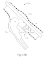
- FIG. 12A depicts a partial side cross-sectional view of an exemplary ratcheted trocar actuator and lockout feature shown in a locked position
- FIG. 12B depicts a partial side cross-sectional view of the ratcheted trocar actuator and lockout feature of FIG. 12A shown in a firing position;
- FIG. 13A depicts a partial side cross-sectional view of an exemplary slotted trocar actuator and lockout feature shown in a locked position
- FIG. 13B depicts a partial side cross-sectional view of the slotted trocar actuator and lockout feature of FIG. 13A shown in a firing position;
- FIG. 14A depicts a partial side cross-sectional view taken along the center of the instrument showing an exemplary two-piece trigger actuation assembly and lockout feature in a locked position;
- FIG. 14B depicts a partial side cross-sectional view of the two-piece trigger actuation assembly and lockout feature of FIG. 14A shown in a firing position;
- FIG. 15 depicts a partial perspective view of a driver actuator of the two-piece trigger actuation assembly of FIGS. 14A-14B showing a ratchet member and a reset button;
- FIG. 16 depicts a side schematic view of the driver actuator, ratchet member, and reset button of FIG. 15 , showing driver actuator engaged with reset button;
- FIG. 17A depicts a partial side cross-sectional view of an exemplary two-piece trigger actuation assembly and exemplary indicator showing a trigger carriage disengaged from a trigger;
- FIG. 17B depicts a partial side cross-sectional view of the trigger actuation assembly of FIG. 17A showing the trigger carriage engaged with the trigger.
- FIGS. 1-6 depict an exemplary circular surgical stapling instrument ( 10 ) having a stapling head assembly ( 20 ), a shaft assembly ( 60 ), and an actuator handle assembly ( 70 ), each of which will be described in more detail below.
- Shaft assembly ( 60 ) extends distally from actuator handle assembly ( 70 ) and stapling head assembly ( 20 ) is coupled to a distal end of shaft assembly ( 60 ).
- actuator handle assembly ( 70 ) is operable to actuate a staple driver ( 24 ) of stapling head assembly ( 20 ) to drive a plurality of staples ( 66 ) out of stapling head assembly ( 20 ).
- Staples ( 66 ) are bent to form completed staples by an anvil ( 40 ) that is attached at the distal end of instrument ( 10 ). Accordingly, tissue ( 2 ), shown in FIGS. 2A-2C , may be stapled utilizing instrument ( 10 ).
- instrument ( 10 ) comprises a closure system and a firing system.
- the closure system comprises a trocar ( 38 ), a trocar actuator ( 39 ), and a rotating knob ( 98 ).
- An anvil ( 40 ) may be coupled to a distal end of trocar ( 38 ).
- Rotating knob ( 98 ) is operable to longitudinally translate trocar ( 38 ) relative to stapling head assembly ( 20 ), thereby translating anvil ( 40 ) when anvil ( 40 ) is coupled to trocar ( 38 ), to clamp tissue between anvil ( 40 ) and stapling head assembly ( 20 ).
- the firing system comprises a trigger ( 74 ), a trigger actuation assembly ( 84 ), a driver actuator ( 64 ), and a staple driver ( 24 ).
- Staple driver ( 24 ) includes a knife ( 36 ) configured to sever tissue when staple driver ( 24 ) is actuated longitudinally.
- staples ( 66 ) are positioned distal to a plurality of staple driving members ( 30 ) of staple driver ( 24 ) such that staple driver ( 24 ) also drives staples ( 66 ) distally when staple driver ( 24 ) is actuated longitudinally.
- trigger ( 74 ) when trigger ( 74 ) is actuated and trigger actuation assembly ( 84 ) actuates staple driver ( 24 ) via driver actuator ( 64 ), knife ( 36 ) and members ( 30 ) substantially simultaneously sever tissue ( 2 ) and drive staples ( 66 ) distally relative to stapling head assembly ( 20 ) into tissue.
- trigger actuator ( 64 ) when trigger ( 74 ) is actuated and trigger actuation assembly ( 84 ) actuates staple driver ( 24 ) via driver actuator ( 64 ), knife ( 36 ) and members ( 30 ) substantially simultaneously sever tissue ( 2 ) and drive staples ( 66 ) distally relative to stapling head assembly ( 20 ) into tissue.
- anvil ( 40 ) is selectively coupleable to instrument ( 10 ) to provide a surface against which staples ( 66 ) may be bent to staple material contained between stapling head assembly ( 20 ) and anvil ( 40 ).
- Anvil ( 40 ) of the present example is selectively coupleable to a trocar or pointed rod ( 38 ) that extends distally relative to stapling head assembly ( 20 ).
- anvil ( 40 ) is selectively coupleable via the coupling of a proximal shaft ( 42 ) of anvil ( 40 ) to a distal tip of trocar ( 38 ).
- Anvil ( 40 ) comprises a generally circular anvil head ( 48 ) and a proximal shaft ( 42 ) extending proximally from anvil head ( 48 ).
- proximal shaft ( 42 ) comprises a tubular member ( 44 ) having resiliently biased retaining clips ( 46 ) to selectively couple anvil ( 40 ) to trocar ( 38 ), though this is merely optional, and it should be understood that other retention features for coupling anvil ( 40 ) to trocar ( 38 ) may be used as well.
- C-clips, clamps, threading, pins, adhesives, etc. may be employed to couple anvil ( 40 ) to trocar ( 38 ).
- proximal shaft ( 42 ) may include a one-way coupling feature such that anvil ( 40 ) cannot be removed from trocar ( 38 ) once anvil ( 40 ) is attached.
- one-way features include barbs, one way snaps, collets, collars, tabs, bands, etc.
- trocar ( 38 ) may instead be a hollow shaft and proximal shaft ( 42 ) may comprise a sharpened rod that is insertable into the hollow shaft.
- Anvil head ( 48 ) of the present example comprises a plurality of staple forming pockets ( 52 ) formed in a proximal face ( 50 ) of anvil head ( 48 ). Accordingly, when anvil ( 40 ) is in the closed position and staples ( 66 ) are driven out of stapling head assembly ( 20 ) into staple forming pockets ( 52 ), as shown in FIG. 2C , legs ( 68 ) of staples ( 66 ) are bent to form completed staples. It should be understood that staple forming pockets ( 52 ) are merely optional and may be omitted in some versions.
- anvil ( 40 ) may be inserted and secured to a portion of tissue ( 2 ) prior to being coupled to stapling head assembly ( 20 ).
- anvil ( 40 ) may be inserted into and secured to a first tubular portion of tissue ( 2 ) while instrument ( 10 ) is inserted into and secured to a second tubular portion of tissue ( 2 ).
- the first tubular portion of tissue ( 2 ) may be sutured to or about a portion of anvil ( 40 ), and the second tubular portion of tissue ( 2 ) may be sutured to or about trocar ( 38 ).
- Trocar ( 38 ) of the present example is shown in a distal most actuated position. Such an extended position for trocar ( 38 ) may provide a larger area to which tissue ( 2 ) may be coupled prior to attachment of anvil ( 40 ). In addition, the extended position of trocar ( 38 ) may also provide for easier attachment of anvil ( 40 ) to trocar ( 38 ).
- Trocar ( 38 ) further includes a tapered distal tip. Such a tip may be capable of piercing through tissue and/or aiding the insertion of anvil ( 40 ) on to trocar ( 38 ), though the tapered distal tip is merely optional.
- trocar ( 38 ) may have a blunt tip.
- trocar ( 38 ) may include a magnetic portion (not shown) which may attract anvil ( 40 ) towards trocar ( 38 ).
- anvil ( 40 ) and trocar ( 38 ) will be apparent to one of ordinary skill in the art in view of the teachings herein.
- Trocar ( 38 ) of the present example is translatable longitudinally relative to stapling head assembly ( 20 ) via an adjusting knob ( 98 ) located at a proximal end of actuator handle assembly ( 70 ), as will be described in greater detail below. Accordingly, when anvil ( 40 ) is coupled to trocar ( 38 ), rotation of adjusting knob ( 98 ) enlarges or reduces gap distance d by actuating anvil ( 40 ) relative to stapling head assembly ( 20 ).
- anvil ( 40 ) is shown actuating proximally relative to actuator handle assembly ( 70 ) from an initial, open position to a closed position, thereby reducing the gap distance d and the distance between the two portions of tissue ( 2 ) to be joined.
- stapling head assembly ( 20 ) may be fired, as shown in FIG. 2C , to staple and sever tissue ( 2 ) between anvil ( 40 ) and stapling head assembly ( 20 ).
- Stapling head assembly ( 20 ) is operable to staple and sever tissue ( 2 ) by a user pivoting a trigger ( 74 ) of actuator handle assembly ( 70 ), as will be described in greater detail below.
- gap distance d corresponds to the distance between anvil ( 40 ) and stapling head assembly ( 20 ).
- this gap distance d may not be easily viewable.
- a moveable indicator bar ( 110 ) shown in FIGS. 5-6 , is provided to be visible through an indicator window ( 120 ) positioned opposite to trigger ( 74 ).
- Indicator bar ( 110 ) is operable to move in response to rotation of adjusting knob ( 98 ) such that the position of indicator bar ( 110 ) is representative of the gap distance d. As shown in FIG.
- indicator window ( 120 ) further comprises a scale ( 130 ) which indicates that the anvil gap is within a desired operating range (e.g., a green colored region or “green zone”) and a corresponding staple compression representation at each end of scale ( 130 ).
- a desired operating range e.g., a green colored region or “green zone”
- a corresponding staple compression representation at each end of scale ( 130 ).
- a first staple image ( 132 ) depicts a large staple height while a second staple image ( 134 ) depicts a small staple height.
- a user can view the position of the coupled anvil ( 40 ) relative to the stapling head assembly ( 20 ) via indicator bar ( 110 ) and scale ( 130 ). The user may then adjust the positioning of anvil ( 40 ) via adjusting knob ( 98 ) accordingly.
- a user sutures a portion of tissue ( 2 ) about tubular member ( 44 ) such that anvil head ( 48 ) is located within a portion of the tissue ( 2 ) to be stapled.
- tissue ( 2 ) is attached to anvil ( 40 )
- retaining clips ( 46 ) and a portion of tubular member ( 44 ) protrude out from tissue ( 2 ) such that the user may couple anvil ( 40 ) to trocar ( 38 ).
- tissue ( 2 ) coupled to trocar ( 38 ) and/or another portion of stapling head assembly ( 20 ) the user attaches anvil ( 40 ) to trocar ( 38 ) and actuates anvil ( 40 ) proximally towards stapling head assembly ( 20 ) to reduce the gap distance d.
- instrument ( 10 ) is within the operating range, the user then staples together the ends of tissue ( 2 ), thereby forming a substantially contiguous tubular portion of tissue ( 2 ).
- Anvil ( 40 ) may be further constructed in accordance with at least some of the teachings of U.S. Pat. No. 5,205,459; U.S. Pat. No. 5,271,544; U.S. Pat. No. 5,275,322; U.S. Pat. No. 5,285,945; U.S. Pat. No. 5,292,053; U.S. Pat. No. 5,333,773; U.S. Pat. No. 5,350,104; U.S. Pat. No. 5,533,661, the disclosures of which are incorporated by reference herein; and/or in accordance with other configurations as will be apparent to one of ordinary skill in the art in view of the teachings herein.
- Stapling head assembly ( 20 ) of the present example is coupled to a distal end of shaft assembly ( 60 ) and comprises a tubular casing ( 22 ) housing a slidable staple driver ( 24 ) and a plurality of staples ( 66 ) contained within staple pockets ( 32 ). Staples ( 66 ) and staple pockets ( 32 ) are disposed in a circular array about tubular casing ( 22 ). In the present example, staples ( 66 ) and staple pockets ( 32 ) are disposed in a pair of concentric annular rows of staples ( 66 ) and staple pockets ( 32 ).
- Staple driver ( 24 ) is operable to actuate longitudinally within tubular casing ( 22 ) in response to rotation of trigger ( 74 ) of actuator handle assembly ( 70 ).
- staple driver ( 24 ) comprises a flared cylindrical member having a trocar opening ( 26 ), a central recess ( 28 ), and a plurality of members ( 30 ) disposed circumferentially about central recess ( 28 ) and extending distally relative to shaft assembly ( 60 ).
- Each member ( 30 ) is configured to contact and engage a corresponding staple ( 66 ) of the plurality of staples ( 66 ) within staple pockets ( 32 ).
- each member ( 30 ) drives a corresponding staple ( 66 ) out of its staple pocket ( 32 ) through a staple aperture ( 34 ) formed in a distal end of tubular casing ( 22 ). Because each member ( 30 ) extends from staple driver ( 24 ), the plurality of staples ( 66 ) are driven out of stapling head assembly ( 20 ) at substantially the same time.
- FIG. 3 depicts one merely exemplary staple ( 66 ) driven by a member ( 30 ) into a staple forming pocket ( 32 ) of anvil ( 40 ) to bend legs ( 68 ).
- Staple driver ( 24 ) further includes a cylindrical knife ( 36 ) that is coaxial to trocar opening ( 26 ) and inset from staple pockets ( 32 ).
- cylindrical knife ( 36 ) is disposed within central recess ( 28 ) to translate distally with staple driver ( 24 ).
- anvil head ( 48 ) provides a surface against which cylindrical knife ( 36 ) cuts the material contained between anvil ( 40 ) and stapling head assembly ( 20 ).
- anvil head ( 48 ) may include a recess (not shown) for cylindrical knife ( 36 ) to aid in cutting the material (e.g., by providing a cooperative shearing edge).
- anvil head ( 48 ) may include one or more opposing cylindrical knives (not shown) offset from cylindrical knife ( 36 ) such that a scissor-type cutting action may be provided. Still other configurations will be apparent to one of ordinary skill in the art in view of the teachings herein. Stapling head assembly ( 20 ) is thus operable to both staple and cut tissue ( 2 ) substantially simultaneously in response to actuation by actuator handle assembly ( 70 ).
- stapling head assembly ( 20 ) may be further constructed in accordance with at least some of the teachings of U.S. Pat. No. 5,205,459; U.S. Pat. No. 5,271,544; U.S. Pat. No. 5,275,322; U.S. Pat. No. 5,285,945; U.S. Pat. No. 5,292,053; U.S. Pat. No. 5,333,773; U.S. Pat. No. 5,350,104; U.S. Pat. No. 5,533,661, the disclosures of which are incorporated by reference herein; and/or in accordance with other configurations as will be apparent to one of ordinary skill in the art in view of the teachings herein.
- staple driver ( 24 ) includes a trocar opening ( 26 ).
- Trocar opening ( 26 ) is configured to permit trocar ( 38 ) to longitudinally slide relative to stapling head assembly ( 20 ) and/or shaft assembly ( 60 ).
- trocar ( 38 ) is coupled to a trocar actuator ( 39 ) such that trocar ( 38 ) can be actuated longitudinally via rotation of rotating knob ( 98 ), as will be described in greater detail below in reference to actuator handle assembly ( 70 ).
- trocar actuator ( 39 ) comprises an elongated, relatively stiff shaft coupled to trocar ( 38 ), though this is merely optional.
- actuator ( 39 ) may comprise a longitudinally stiff material while permitting lateral bending such that portions of instrument ( 10 ) may be selectively bent or curved during use; or instrument ( 10 ) may include a preset bent shaft assembly ( 60 ).
- One merely exemplary material is nitinol.
- Stapling head assembly ( 20 ) and trocar ( 38 ) are positioned at a distal end of shaft assembly ( 60 ), as shown in FIGS. 2A-2C .
- Shaft assembly ( 60 ) of the present example comprises an outer tubular member ( 62 ) and a driver actuator ( 64 ).
- Outer tubular member ( 62 ) is coupled to tubular casing ( 22 ) of stapling head assembly ( 20 ) and to a body ( 72 ) of actuator handle assembly ( 70 ), thereby providing a mechanical ground for the actuating components therein.
- the proximal end of driver actuator ( 64 ) is coupled to a trigger actuation assembly ( 84 ) of actuator handle assembly ( 70 ), described below.
- driver actuator ( 64 ) is coupled to staple driver ( 24 ) such that the rotation of trigger ( 74 ) longitudinally actuates staple driver ( 24 ).
- driver actuator ( 64 ) comprises a tubular member having an open longitudinal axis such that actuator ( 39 ) coupled to trocar ( 38 ) may actuate longitudinally within and relative to driver actuator ( 64 ).
- driver actuator ( 64 ) may be disposed within driver actuator ( 64 ) as will be apparent to one of ordinary skill in the art in view of the teachings herein.
- Shaft assembly ( 60 ) may be further constructed in accordance with at least some of the teachings of U.S. Pat. No. 5,205,459; U.S. Pat. No. 5,271,544; U.S. Pat. No. 5,275,322; U.S. Pat. No. 5,285,945; U.S. Pat. No. 5,292,053; U.S. Pat. No. 5,333,773; U.S. Pat. No. 5,350,104; U.S. Pat. No. 5,533,661, the disclosures of which are incorporated by reference herein; and/or in accordance with other configurations as will be apparent to one of ordinary skill in the art in view of the teachings herein.
- actuator handle assembly ( 70 ) comprises a body ( 72 ), a trigger ( 74 ), a lockout feature ( 82 ), a trigger actuation assembly ( 84 ), and a trocar actuation assembly ( 90 ).
- Trigger ( 74 ) of the present example is pivotably mounted to body ( 72 ) and is coupled to trigger actuation assembly ( 84 ) such that rotation of trigger ( 74 ) from an unfired position (shown in FIG. 4A ) to a fired position (shown in FIG. 4B ) actuates driver actuator ( 64 ) described above.
- a spring ( 78 ) is coupled to body ( 72 ) and trigger ( 74 ) to bias trigger ( 74 ) towards the unfired position.
- Lockout feature ( 82 ) is a pivotable member that is coupled to body ( 72 ). In a first, locked position, lockout feature ( 82 ) is pivoted upwards and away from body ( 72 ) such that lockout feature ( 82 ) engages trigger ( 74 ) and mechanically resists actuation of trigger ( 74 ) by a user. In a second, unlocked position, such as that shown in FIGS. 1 and 4B , lockout feature ( 82 ) is pivoted downward such that trigger ( 74 ) may be actuated by the user. Accordingly, with lockout feature ( 82 ) in the second position, trigger ( 74 ) can engage a trigger actuation assembly ( 84 ) to fire instrument ( 10 ).
- trigger actuation assembly ( 84 ) of the present example comprises a slidable trigger carriage ( 86 ) engaged with a proximal end of driver actuator ( 64 ).
- Carriage ( 86 ) includes a set of tabs ( 88 ) on a proximal end of carriage ( 86 ) to retain and engage a pair of trigger arms ( 76 ) extending from trigger ( 74 ). Accordingly, when trigger ( 74 ) is pivoted, carriage ( 86 ) is actuated longitudinally and transfers the longitudinal motion to driver actuator ( 64 ).
- carriage ( 86 ) is fixedly coupled to the proximal end of driver actuator ( 64 ), though this is merely optional. Indeed, in one merely exemplary alternative, carriage ( 86 ) may simply abut driver actuator ( 64 ) while a distal spring (not shown) biases driver actuator ( 64 ) proximally relative to actuator handle assembly ( 70 ).
- Trigger actuation assembly ( 84 ) may be further constructed in accordance with at least some of the teachings of U.S. Pat. No. 5,205,459; U.S. Pat. No. 5,271,544; U.S. Pat. No. 5,275,322; U.S. Pat. No. 5,285,945; U.S. Pat. No. 5,292,053; U.S. Pat. No. 5,333,773; U.S. Pat. No. 5,350,104; U.S. Pat. No. 5,533,661, the disclosures of which are incorporated by reference herein; and/or in accordance with other configurations as will be apparent to one of ordinary skill in the art in view of the teachings herein.
- Body ( 72 ) also houses a trocar actuation assembly ( 90 ) configured to actuate trocar ( 38 ) longitudinally in response to rotation of adjusting knob ( 98 ).
- trocar actuation assembly ( 90 ) of the present example comprises adjusting knob ( 98 ), a grooved shank ( 94 ), and a sleeve ( 92 ).
- Grooved shank ( 94 ) of the present example is located at a distal end of trocar actuator ( 39 ), though it should be understood that grooved shank ( 94 ) and trocar actuator ( 39 ) may alternatively be separate components that engage to transmit longitudinal movement.
- Adjusting knob ( 98 ) is rotatably supported by the proximal end of body ( 72 ) and is operable to rotate sleeve ( 92 ) that is engaged with grooved shank ( 94 ) via an internal tab (not shown).
- Grooved shank ( 94 ) of the present example comprises a continuous groove ( 96 ) formed in the outer surface of grooved shank ( 94 ). Accordingly, when adjusting knob ( 98 ) is rotated, the internal tab rides within groove ( 96 ) and grooved shank ( 94 ) is longitudinally actuated relative to sleeve ( 92 ).
- trocar actuator ( 39 ) Since grooved shank ( 94 ) is located at the distal end of trocar actuator ( 39 ), rotating adjusting knob ( 98 ) in a first direction advances trocar actuator ( 39 ) distally relative to actuator handle assembly ( 70 ). Accordingly, the gap distance d between anvil ( 40 ) and stapling head assembly ( 20 ) is increased.
- trocar actuator ( 39 ) By rotating adjusting knob ( 98 ) in the opposite direction, trocar actuator ( 39 ) is actuated proximally relative to actuator handle assembly ( 70 ) to reduce the gap distance d between anvil ( 40 ) and stapling head assembly ( 20 ).
- trocar actuation assembly ( 90 ) is operable to actuate trocar ( 38 ) in response to rotating adjustment knob ( 98 ).
- other configurations for trocar actuation assembly ( 90 ) will be apparent to one of ordinary skill in the art in view of the teachings herein.
- Groove ( 96 ) of the present example comprises a plurality of different portions ( 96 A, 96 B, 96 C) that have a varying pitch or number of grooves per axial distance.
- the present groove ( 96 ) is divided into a distal portion ( 96 A), a middle portion ( 96 B) and a proximal portion ( 96 C).
- distal portion ( 96 A) comprises a fine pitch or a high number of grooves over a short axial distance of grooved shank ( 94 ) such that a large number of rotations of adjusting knob ( 98 ) are required to traverse the short axial distance.
- Middle portion ( 96 B) comprises a section with comparably coarser pitch or fewer grooves per axial distance such that relatively few rotations are required to traverse a long axial distance. Accordingly, the gap distance d may be quickly reduced through relatively few rotations of adjusting knob ( 98 ).
- Proximal portion ( 96 C) of the present example is substantially similar to distal portion ( 96 A) and comprises a fine pitch or a high number of grooves over a short axial distance of grooved shank ( 94 ) such that a large number of rotations are required to traverse the short axial distance.
- Proximal portion ( 96 C) of the present example is positioned within sleeve ( 92 ) when anvil ( 40 ) is substantially near to stapling head assembly ( 20 ) such that indicator bar ( 110 ) moves within indicator window ( 120 ) along scale ( 130 ) to indicate that the anvil gap is within a desired operating range, as will be described in more detail below. Accordingly, when the tab is within proximal portion ( 96 C) of groove ( 96 ), each rotation of adjusting knob ( 98 ) may reduce the gap distance d by a small amount to provide for fine tuning.
- Trocar actuation assembly ( 90 ) may be further constructed in accordance with at least some of the teachings of U.S. Pat. No. 5,205,459; U.S. Pat. No. 5,271,544; U.S. Pat. No. 5,275,322; U.S. Pat. No. 5,285,945; U.S. Pat. No. 5,292,053; U.S. Pat. No. 5,333,773; U.S. Pat. No. 5,350,104; U.S. Pat. No. 5,533,661, the disclosures of which are incorporated by reference herein; and/or in accordance with other configurations as will be apparent to one of ordinary skill in the art in view of the teachings herein.
- a U-shaped clip ( 100 ) is attached to an intermediate portion of trocar actuator ( 39 ) located distally of grooved shank ( 94 ).
- U-shaped clip ( 100 ) engages with a portion of body ( 72 ) to substantially prevent trocar actuator ( 39 ) from rotating about its axis when adjusting knob ( 98 ) is rotated.
- U-shaped clip ( 100 ) further includes an elongated slot ( 102 ) on each of its opposite sides for receiving an attachment member, such as a screw, bolt, pin, clip, etc., to selectively adjust the longitudinal position of elongated slot ( 102 ) of U-shaped clip ( 100 ) relative to trocar actuator ( 39 ) for purposes of calibrating indicator bar ( 110 ) relative to scale ( 130 ).
- an attachment member such as a screw, bolt, pin, clip, etc.
- actuator handle assembly ( 70 ) further includes an indicator bracket ( 140 ) configured to engage and pivot an indicator ( 104 ).
- Indicator bracket ( 140 ) of the present example is slidable relative to body ( 72 ) along a pair of slots formed on body ( 72 ).
- Indicator bracket ( 140 ) comprises a rectangular plate ( 144 ), an indicator arm ( 146 ), and an angled flange ( 142 ).
- Angled flange ( 142 ) is formed at the proximal end of rectangular plate ( 144 ) and includes an aperture (not shown) to slidable mount onto trocar actuator ( 39 ) and/or grooved shank ( 94 ).
- a coil spring ( 150 ) is interposed between flange ( 142 ) and a boss ( 152 ) to bias flange ( 142 ) against U-shaped clip ( 100 ). Accordingly, when U-shaped clip ( 100 ) actuates distally with trocar actuator ( 39 ) and/or grooved shank ( 94 ), coil spring ( 150 ) urges indicator bracket ( 140 ) to travel distally with U-shaped clip ( 100 ). In addition, U-shaped clip ( 100 ) urges indicator bracket ( 140 ) proximally relative to boss ( 152 ) when trocar actuator ( 39 ) and/or grooved shank ( 94 ) translate proximally, thereby compressing coil spring ( 150 ). Of course, it should be understood that in some versions indicator bracket ( 140 ) may be fixedly attached to trocar actuator ( 39 ) and/or grooved shank ( 94 ).
- a portion of lockout feature ( 82 ) abuts a surface ( 141 ) of indicator bracket ( 140 ) when indicator bracket ( 140 ) is in a longitudinal position that does not correspond to when the anvil gap is within a desired operating range (e.g., a green colored region or “green zone”).
- a desired operating range e.g., a green colored region or “green zone”.
- indicator bracket ( 140 ) narrows to provide a pair of gaps ( 145 ) on either side of an indicator arm ( 146 ) that permits lockout feature ( 82 ) to pivot, thereby releasing trigger ( 74 ).
- lockout feature ( 82 ) and indicator bracket ( 140 ) can substantially prevent a user from releasing and operating trigger ( 74 ) until anvil ( 40 ) is in a predetermined operating range.
- lockout feature ( 82 ) may be omitted entirely in some versions.
- This operating range may be visually communicated to the user via an indicator bar ( 110 ) of an indicator ( 104 ) shown against a scale ( 130 ), described briefly above.
- indicator bracket ( 140 ) At the distal end of indicator bracket ( 140 ) is a distally projecting indicator arm ( 146 ) which terminates at a laterally projecting finger ( 148 ) for controlling the movement of indicator ( 104 ).
- Indicator arm ( 146 ) and finger ( 148 ), best shown in FIG. 5 are configured to engage a tab ( 106 ) of indicator ( 104 ) such that indicator ( 104 ) is pivoted when indicator bracket ( 140 ) is actuated longitudinally.
- indicator ( 104 ) is pivotably coupled to body ( 72 ) at a first end of indicator ( 104 ), though this is merely optional and other pivot points for indicator ( 104 ) will be apparent to one of ordinary skill in the art in view of the teachings herein.
- An indicator bar ( 110 ) is positioned on the second end of indicator ( 104 ) such that indicator bar ( 110 ) moves in response to the actuation of indicator bracket ( 140 ). Accordingly, as discussed above, indicator bar ( 110 ) is displayed through an indicator window ( 120 ) against a scale ( 130 ) (shown in FIG. 6 ) to show the relative gap distance d between anvil ( 40 ) and stapling head assembly ( 20 ).
- indicator bracket ( 140 ), indicator ( 104 ), and/or actuator handle assembly ( 70 ) may be further constructed in accordance with at least some of the teachings of U.S. Pat. No. 5,205,459; U.S. Pat. No. 5,271,544; U.S. Pat. No. 5,275,322; U.S. Pat. No. 5,285,945; U.S. Pat. No. 5,292,053; U.S. Pat. No. 5,333,773; U.S. Pat. No. 5,350,104; U.S. Pat. No. 5,533,661, the disclosures of which are incorporated by reference herein; and/or in accordance with other configurations as will be apparent to one of ordinary skill in the art in view of the teachings herein.
- trocar actuator ( 39 ) it may be useful to a user to lock trocar actuator ( 39 ) in position once lockout feature ( 82 ) is disengaged.
- some users may inadvertently twist adjusting knob ( 98 ) when pulling trigger ( 74 ). Twisting adjusting knob ( 98 ) may result in anvil ( 40 ) actuating proximally or distally from a desired position relative to stapling head assembly ( 20 ). Accordingly, the staple size may become too small or too large, or, in some instances, anvil ( 40 ) may be actuated such that incomplete stapling of staples ( 66 ) occurs (i.e., anvil ( 40 ) is no longer in the “green zone”). Accordingly, securing trocar actuator ( 39 ) from actuating proximally or distally once lockout feature ( 82 ) is disengaged may reduce the likelihood of such occurrences.
- FIGS. 7A-7B depict an exemplary actuator handle assembly ( 200 ) for surgical instrument ( 10 ), described above, having a body ( 202 ), a trigger ( 210 ) pivotably mounted to body ( 202 ), and a trocar actuator ( 220 ) extending longitudinally through body ( 202 ).
- trocar actuator ( 220 ) is coupled to an anvil (not shown), such as anvil ( 40 ), at a distal end.
- a proximal end of trocar actuator ( 220 ) is in communication with an adjusting knob (not shown), such as adjusting knob ( 98 ), to actuate trocar actuator ( 220 ) proximally and/or distally relative to actuator handle assembly ( 200 ).
- trocar actuator ( 220 ) increases or decreases the distance between the anvil and a stapling head assembly (not shown).
- Trigger ( 210 ) is operable to drive staples (not shown) out of the stapling head assembly and into tissue.
- Body ( 202 ), trigger ( 210 ), trocar actuator ( 220 ) and/or actuator handle assembly ( 200 ) may be further constructed in accordance with at least some of the teachings of body ( 72 ), trigger ( 74 ), trocar actuator ( 39 ), and/or actuator handle assembly ( 70 ) described above.
- a lockout feature ( 230 ) is also pivotably coupled to body ( 202 ) and is configured to pivot between a first position shown in FIG. 7A , in which lockout feature ( 230 ) is engaged with trigger ( 210 ) to substantially prevent trigger ( 210 ) from being fired, and a second position shown in FIG. 7B , in which lockout feature ( 230 ) is disengaged from trigger ( 210 ).
- Lockout feature ( 230 ) may be constructed and/or function at least partially in accordance with lockout feature ( 82 ) described above.
- lockout feature ( 230 ) includes a cam surface ( 232 ) that interacts with a spring-loaded brake ( 240 ).
- cam surface ( 232 ) may comprise a frictional material, such as rubber, that engages brake ( 240 ) to resist longitudinal movement of brake ( 240 ) relative to cam surface ( 232 ).
- Brake ( 240 ) comprises a plate ( 242 ) and an engagement feature ( 244 ) extending from plate ( 242 ).
- a pair of springs ( 246 ) are disposed between plate ( 242 ) and bosses ( 204 ) of body ( 202 ) to bias brake ( 240 ) toward cam surface ( 242 ).
- springs ( 246 ) are merely optional and may be omitted.
- lockout feature ( 230 ) may include a retention member (not shown) configured to selectively secure lockout feature ( 230 ) to body ( 202 ) such that lockout feature ( 230 ) is not pivoted back to the first position via the bias provided by springs ( 246 ).
- brake ( 240 ) may be coupled to trocar actuator ( 220 ) and plate ( 242 ) may extend longitudinally such that lockout feature ( 230 ) engages brake ( 240 ) at any longitudinal position.
- Engagement feature ( 244 ) of the present example comprises a square tab extending from plate ( 242 ) and is configured to selectively enter a notch or recess ( 222 ) formed in trocar actuator ( 220 ).
- engagement feature ( 244 ) may include other sized tabs, meshing teeth, ratcheting features, and/or any other feature as will be apparent to one of ordinary skill in the art in view of the teachings herein.
- Recess ( 222 ) has a longitudinal length corresponding to the longitudinal path of trocar actuator ( 220 ) when actuated within the “green zone” described above. Accordingly, when engagement feature ( 244 ) is inserted into recess ( 222 ), trocar actuator ( 220 ) is actuatable within the “green zone,” but engagement feature ( 244 ) abuts an end ( 224 ) of recess ( 222 ) when either limit of the “green zone” is reached.
- recess ( 222 ) may include a smaller or larger longitudinal length.
- FIG. 7A shows lockout feature ( 230 ) in the locked position such that trigger ( 210 ) is inoperable by the user.
- engagement feature ( 244 ) is positioned adjacent to at least a portion of recess ( 222 ).
- cam surface ( 232 ) engages brake ( 240 ) to insert engagement feature ( 244 ) into recess ( 222 ).
- trocar actuator ( 220 ) may then actuate trocar actuator ( 220 ), but only within the “green zone.” If the user attempts to move trocar actuator ( 220 ) out of the “green zone” while lockout feature ( 230 ) is disengaged, engagement feature ( 244 ) is impeded by either end ( 224 ) of recess ( 222 ).
- recess ( 222 ) may be sized such that trocar actuator ( 220 ) cannot be longitudinally actuated once lockout feature ( 230 ) is disengaged.
- a plurality of small recesses ( 222 ) may be disposed along the length of trocar actuator ( 220 ) to provide a plurality of locking positions for engagement feature ( 244 ).
- trocar actuator ( 220 ) secured relative to body ( 202 ) via brake ( 240 )
- the user may then fire the instrument to staple the tissue.
- brake ( 240 ) and/or lockout feature ( 230 ) will be apparent to one of ordinary skill in the art in view of the teachings herein.
- FIGS. 8A-8B depict an exemplary actuator handle assembly ( 300 ) for surgical instrument ( 10 ), described above, having a body ( 302 ), a trigger ( 310 ) pivotably mounted to body ( 302 ), and a trocar actuator ( 320 ) extending longitudinally through body ( 302 ).
- trocar actuator ( 320 ) is coupled to an anvil (not shown), such as anvil ( 40 ), at a distal end.
- a proximal end of trocar actuator ( 320 ) is in communication with an adjusting knob (not shown), such as adjusting knob ( 98 ), to actuate trocar actuator ( 320 ) proximally and/or distally relative to actuator handle assembly ( 300 ).
- trocar actuator ( 320 ) increases or decreases the distance between the anvil and a stapling head assembly (not shown).
- Trigger ( 310 ) is operable to drive staples (not shown) out of the stapling head assembly and into tissue.
- Body ( 302 ), trigger ( 310 ), trocar actuator ( 320 ) and/or actuator handle assembly ( 300 ) may be further constructed in accordance with at least some of the teachings of body ( 72 ), trigger ( 74 ), trocar actuator ( 39 ), and/or actuator handle assembly ( 70 ) described above.
- a lockout feature ( 330 ) is also pivotably coupled to body ( 302 ) and is configured to pivot between a first position shown in FIG. 8A , in which lockout feature ( 330 ) is engaged with trigger ( 310 ) to substantially prevent trigger ( 310 ) from being fired, and a second position shown in FIG. 8B , in which lockout feature ( 330 ) is disengaged from trigger ( 310 ).
- Lockout feature ( 330 ) may be constructed and/or function at least partially in accordance with lockout feature ( 82 ) described above.
- lockout feature ( 330 ) includes a cam surface ( 332 ) that interacts with a screen door lock ( 340 ).
- Screen door lock ( 340 ) is pivotably coupled to body ( 302 ) at a first end ( 342 ).
- a second end ( 344 ) of screen door lock ( 340 ) is coupled to a spring ( 350 ) that is also coupled to a portion of body ( 302 ).
- Spring ( 350 ) of the present example is a compression spring configured to bias second end ( 344 ) into cam surface ( 332 ).
- lockout feature ( 330 ) may include a retention member (not shown) configured to selectively secure lockout feature ( 330 ) to body ( 302 ) such that lockout feature ( 330 ) is not pivoted back to the first position via the bias provided by spring ( 350 ).
- spring ( 350 ) may be omitted and screen door lock ( 340 ) may be linked or otherwise coupled to lockout feature ( 340 ).
- screen door lock ( 340 ) also includes an opening ( 346 ) formed therethrough and comprises an edge ( 348 ) configured to engage one or more teeth ( 322 ) formed on an outer portion of trocar actuator ( 320 ).
- edge ( 348 ) may include a frictional material, such as rubber, configured to frictionally resist movement of trocar actuator ( 320 ).
- trocar actuator ( 320 ) extends through and is longitudinally actuatable relative to opening ( 346 ).
- a plurality of teeth ( 322 ) are formed on the exterior of trocar actuator ( 320 ), though it should be understood that a plurality of notches may be formed in trocar actuator ( 320 ) and/or a single tooth or notch may be provided for edge ( 348 ) to lock into.
- a plurality of notches may be formed in trocar actuator ( 320 ) and/or a single tooth or notch may be provided for edge ( 348 ) to lock into.
- screen door lock ( 340 ) and/or trocar actuator ( 320 ) will be apparent to one of ordinary skill in the art in view of the teachings herein.
- FIG. 8A shows lockout feature ( 330 ) in the locked position such that trigger ( 310 ) is inoperable by the user.
- the user can rotate the adjusting knob to actuate the anvil (and therefore also trocar actuator ( 320 )) into the “green zone.”
- trocar actuator ( 320 ) With screen door lock ( 340 ) shown in a first position with edge ( 348 ) not engaged with teeth ( 322 ), trocar actuator ( 320 ) can move longitudinally through opening ( 346 ) in response to a rotation of the adjusting knob. Accordingly, the user may adjust to position of the anvil relative to the stapling head assembly.
- lockout feature ( 330 ) is pivoted to the second position, shown in FIG.
- cam surface ( 332 ) engages and pivots screen door lock ( 340 ) to its second position.
- edge ( 348 ) engages with teeth ( 322 ) and screen door lock ( 340 ) substantially prevents trocar actuator ( 320 ) from actuating longitudinally.
- screen door lock ( 340 ) maintains the position of trocar actuator ( 320 ) and the anvil relative to the stapling head assembly. With trocar actuator ( 320 ) secured relative to body ( 302 ) via screen door lock ( 340 ), the user may then fire the instrument to staple the tissue.
- Yet other configurations for screen door lock ( 340 ) and/or lockout feature ( 330 ) will be apparent to one of ordinary skill in the art in view of the teachings herein.
- FIGS. 9A-9B depict an exemplary actuator handle assembly ( 400 ) for surgical instrument ( 10 ), described above, having a body ( 402 ), a trigger ( 410 ) pivotably mounted to body ( 402 ), and a trocar actuator ( 420 ) extending longitudinally through body ( 402 ).
- trocar actuator ( 420 ) is coupled to an anvil (not shown), such as anvil ( 40 ), at a distal end.
- a proximal end of trocar actuator ( 420 ) is in communication with an adjusting knob (not shown), such as adjusting knob ( 98 ), to actuate trocar actuator ( 420 ) proximally and/or distally relative to actuator handle assembly ( 400 ).
- trocar actuator ( 420 ) increases or decreases the distance between the anvil and a stapling head assembly (not shown).
- Trigger ( 410 ) is operable to drive staples (not shown) out of the stapling head assembly and into tissue.
- Body ( 402 ), trigger ( 410 ), trocar actuator ( 420 ) and/or actuator handle assembly ( 400 ) may be further constructed in accordance with at least some of the teachings of body ( 72 ), trigger ( 74 ), trocar actuator ( 39 ), and/or actuator handle assembly ( 70 ) described above.
- a lockout feature ( 430 ) is also pivotably coupled to body ( 402 ) and is configured to pivot between a first position shown in FIG. 9A , in which lockout feature ( 430 ) is engaged with trigger ( 410 ) to substantially prevent trigger ( 410 ) from being fired, and a second position shown in FIG. 9B , in which lockout feature ( 430 ) is disengaged from trigger ( 410 ).
- Lockout feature ( 430 ) may be constructed and/or function at least partially in accordance with lockout feature ( 82 ) described above.
- Lockout feature ( 430 ) further includes a cam surface ( 432 ) that engages with a portion of trocar actuator ( 420 ) to substantially prevent trocar actuator ( 420 ) from actuating longitudinally. As shown, cam surface ( 432 ) enters into a recess ( 422 ) formed in trocar actuator ( 420 ), though this is merely optional. In some instances, cam surface ( 432 ) may directly engage an outer surface of trocar actuator ( 420 ).
- recess ( 422 ) is positioned such that lockout feature ( 430 ) is pivotable from the locked position only when trocar actuator ( 420 ) and the anvil are in a position corresponding to the “green zone.”
- a frictional material such as rubber, of cam surface ( 432 ) engages with a surface of trocar actuator ( 420 ) to frictionally resist movement of trocar actuator ( 420 ).
- lockout feature ( 430 ) may include a retention member (not shown) configured to selectively secure lockout feature ( 420 ) to body ( 402 ) such that lockout feature ( 430 ) is not pivoted back to the first position if trocar actuator is moved.
- FIG. 9A shows lockout feature ( 430 ) in the locked position such that trigger ( 410 ) is inoperable by the user.
- the adjusting knob to actuate the anvil (and therefore also trocar actuator ( 420 )) into the “green zone,” at least a portion of recess ( 422 ) is aligned with lockout feature ( 430 ).
- cam surface ( 432 ) engages recess ( 422 ) to frictionally resist movement of trocar actuator ( 420 ).
- trocar actuator ( 420 ) frictionally maintains the position of trocar actuator ( 420 ) and the anvil relative to the stapling head assembly. With trocar actuator ( 420 ) secured relative to body ( 402 ) via cam surface ( 432 ), the user may then fire the instrument to staple the tissue. Still other configurations for trocar actuator ( 420 ) and/or lockout feature ( 430 ) will be apparent to one of ordinary skill in the art in view of the teachings herein.
- FIGS. 10A-10B depict an exemplary actuator handle assembly ( 500 ) for surgical instrument ( 10 ), described above, having a body ( 502 ), a trigger ( 510 ) pivotably mounted to body ( 502 ), and a trocar actuator ( 520 ) extending longitudinally through body ( 502 ).
- trocar actuator ( 520 ) is coupled to an anvil (not shown), such as anvil ( 40 ), at a distal end.
- a proximal end of trocar actuator ( 520 ) is in communication with an adjusting knob (not shown), such as adjusting knob ( 98 ), to actuate trocar actuator ( 520 ) proximally and/or distally relative to actuator handle assembly ( 500 ).
- trocar actuator ( 520 ) increases or decreases the distance between the anvil and a stapling head assembly (not shown).
- Trigger ( 510 ) is operable to drive staples (not shown) out of the stapling head assembly and into tissue.
- Body ( 502 ), trigger ( 510 ), trocar actuator ( 520 ) and/or actuator handle assembly ( 500 ) may be further constructed in accordance with at least some of the teachings of body ( 72 ), trigger ( 74 ), trocar actuator ( 39 ), and/or actuator handle assembly ( 70 ) described above.
- a lockout feature ( 530 ) is also pivotably coupled to body ( 502 ) and is configured to pivot between a first position shown in FIG. 10A , in which lockout feature ( 530 ) is engaged with trigger ( 510 ) to substantially prevent trigger ( 510 ) from being fired, and a second position shown in FIG. 10B , in which lockout feature ( 530 ) is disengaged from trigger ( 510 ).
- Lockout feature ( 530 ) may be constructed and/or function at least partially in accordance with lockout feature ( 82 ) described above.
- Lockout feature ( 530 ) of this example includes a cam surface ( 532 ) configured to engage and actuate a door ( 540 ) relative to body ( 502 ).
- cam surface ( 532 ) may be positioned 90 degrees relative to the main portion of lockout feature ( 530 ) such that cam surface ( 532 ) does not engage door ( 540 ) until lockout feature ( 530 ) is pivoted 90 degrees relative to body ( 502 ), though this is merely optional.
- Door ( 540 ) comprises a flat plate having an opening ( 542 ) through which trocar actuator ( 520 ) extends. As shown in FIGS. 10A-10B , door ( 540 ) includes a top portion ( 544 ) and a bottom portion ( 546 ) on opposing sides of opening ( 542 ).
- top portion ( 544 ) When door ( 540 ) is not actuated by lockout feature ( 530 ), top portion ( 544 ) abuts a portion of trocar actuator ( 520 ) and bottom portion ( 546 ) is disengaged from one or more recesses ( 522 ) formed in trocar actuator ( 520 ), as will be discussed in more detail below.
- a spring ( 548 ) is coupled to top portion ( 544 ) and body ( 502 ) to bias door ( 540 ) to the unactuated position shown in FIG. 10A .
- Bottom portion ( 546 ) is sized to enter the one or more recesses ( 522 ) when door ( 540 ) is actuated by cam surface ( 532 ) of lockout feature ( 530 ).
- Trocar actuator ( 520 ) comprises a plurality of lateral recesses ( 522 ) formed in trocar actuator ( 520 ).
- recesses ( 522 ) are formed in trocar actuator ( 520 ) such that recesses ( 522 ) are adjacent to bottom portion ( 546 ) when trocar actuator ( 520 ) and the anvil are in the “green zone.” Accordingly, recesses ( 522 ) form a plurality of discrete positions where bottom portion ( 546 ) can selectively lock trocar actuator ( 520 ) when door ( 540 ) is actuated by lockout feature ( 530 ).
- FIG. 10A shows lockout feature ( 530 ) in the locked position such that trigger ( 510 ) is inoperable by the user.
- the adjusting knob to actuate the anvil (and therefore also trocar actuator ( 520 )) into the “green zone”
- one or more of the plurality of recesses ( 522 ) are positioned adjacent to bottom portion ( 546 ) of door ( 540 ).
- cam surface ( 532 ) actuates door ( 540 ) to push bottom portion ( 546 ) into one of the plurality of recesses ( 522 ).
- trocar actuator ( 520 ) and the anvil relative to the stapling head assembly With trocar actuator ( 520 ) secured relative to body ( 502 ) via door ( 540 ), the user may then fire the instrument to staple the tissue.
- Other constructions for trocar actuator ( 520 ) and/or door ( 540 ) will be apparent to one of ordinary skill in the art in view of the teachings herein.
- FIGS. 11A-11B depict an exemplary actuator handle assembly ( 600 ) for surgical instrument ( 10 ), described above, having a body ( 602 ), a trigger ( 610 ) pivotably mounted to body ( 602 ), and a trocar actuator ( 620 ) extending longitudinally through body ( 602 ).
- trocar actuator ( 620 ) is coupled to an anvil (not shown), such as anvil ( 40 ), at a distal end.
- a proximal end of trocar actuator ( 620 ) is in communication with an adjusting knob (not shown), such as adjusting knob ( 98 ), to actuate trocar actuator ( 620 ) proximally and/or distally relative to actuator handle assembly ( 600 ).
- trocar actuator ( 620 ) increases or decreases the distance between the anvil and a stapling head assembly (not shown).
- Trigger ( 610 ) is operable to drive staples (not shown) out of the stapling head assembly and into tissue.
- Body ( 602 ), trigger ( 610 ), trocar actuator ( 620 ) and/or actuator handle assembly ( 600 ) may be further constructed in accordance with at least some of the teachings of body ( 72 ), trigger ( 74 ), trocar actuator ( 39 ), and/or actuator handle assembly ( 70 ) described above.
- a lockout feature ( 630 ) is also pivotably coupled to body ( 602 ) and is configured to pivot between a first position shown in FIG. 11A , in which lockout feature ( 630 ) is engaged with trigger ( 610 ) to substantially prevent trigger ( 610 ) from being fired, and a second position shown in FIG. 11B , in which lockout feature ( 630 ) is disengaged from trigger ( 610 ).
- Lockout feature ( 630 ) may be constructed and/or function at least partially in accordance with lockout feature ( 82 ) described above.
- Lockout feature ( 630 ) further includes an engagement head ( 632 ) having one or more locking members ( 634 ), such as gear teeth, configured to engage one or more complementary members ( 622 ) on trocar actuator ( 620 ).
- Complementary members ( 622 ) are formed in trocar actuator ( 620 ) such that complementary members ( 622 ) mesh with locking members ( 634 ) only when trocar actuator ( 620 ) and the anvil are in the “green zone.” Accordingly, complementary members ( 622 ) form a plurality of discrete positions where locking members ( 634 ) can selectively lock trocar actuator ( 620 ).
- complementary members ( 622 ) may extend along the entire longitudinal length of trocar actuator ( 620 ) or any other portion thereof.
- locking members ( 634 ) comprise three gear teeth that mesh with a plurality of complementary gear teeth on trocar actuator ( 620 ).
- Other meshing members ( 622 , 634 ) will be apparent to one of ordinary skill in the art in view of the teachings herein.
- locking members ( 634 ) of engagement head ( 632 ) may be positioned 90 degrees relative to the main portion of lockout feature ( 630 ) such that locking members ( 634 ) do not engage trocar actuator ( 620 ) until lockout feature ( 630 ) is pivoted 90 degrees relative to body ( 602 ), though this is merely optional.
- Still further configurations for lockout feature ( 630 ) will be apparent to one of ordinary skill in the art in view of the teachings herein.
- FIG. 11A shows lockout feature ( 630 ) in the locked position such that trigger ( 610 ) is inoperable by the user.
- the adjusting knob to actuate the anvil (and therefore also trocar actuator ( 620 )) into the “green zone”
- one or more of the complementary members ( 622 ) are positioned adjacent to engagement head ( 632 ) of locking feature ( 630 ).
- lockout feature ( 630 ) is pivoted to the second position, shown in FIG. 11B , locking members ( 634 ) of engagement head ( 632 ) mesh with complementary members ( 622 ).
- Locking members ( 634 ) and complementary members ( 622 ) may be sized such that minimal distal movement of trocar actuator ( 620 ) occurs when locking members ( 634 ) mesh with complementary members ( 622 ).
- locking members ( 634 ) may comprise resilient ratchet teeth that compress against engagement head ( 632 ) when meshing with complementary members ( 622 ). The meshing of locking members ( 634 ) with complementary members ( 622 ) substantially restricts the longitudinal movement of trocar actuator ( 620 ). Thus, if a user inadvertently applies a rotational force on the adjusting knob, locking members ( 634 ) maintain the position of trocar actuator ( 620 ) and the anvil relative to the stapling head assembly.
- trocar actuator ( 620 ) With trocar actuator ( 620 ) secured relative to body ( 602 ) via members ( 622 , 634 ), the user may then fire the instrument to staple the tissue. Further configurations for trocar actuator ( 620 ) and/or complementary members ( 622 ) will be apparent to one of ordinary skill in the art in view of the teachings herein.
- FIGS. 12A-12B depict an exemplary actuator handle assembly ( 700 ) for surgical instrument ( 10 ), described above, having a body ( 702 ), a trigger ( 710 ) pivotably mounted to body ( 702 ), and a trocar actuator ( 720 ) extending longitudinally through body ( 702 ).
- trocar actuator ( 720 ) is coupled to an anvil (not shown), such as anvil ( 40 ), at a distal end.
- a proximal end of trocar actuator ( 720 ) is in communication with an adjusting knob (not shown), such as adjusting knob ( 98 ), to actuate trocar actuator ( 720 ) proximally and/or distally relative to actuator handle assembly ( 700 ).
- trocar actuator ( 720 ) increases or decreases the distance between the anvil and a stapling head assembly (not shown).
- Trigger ( 710 ) is operable to drive staples (not shown) out of the stapling head assembly and into tissue.
- Body ( 702 ), trigger ( 710 ), trocar actuator ( 720 ) and/or actuator handle assembly ( 700 ) may be further constructed in accordance with at least some of the teachings of body ( 72 ), trigger ( 74 ), trocar actuator ( 39 ), and/or actuator handle assembly ( 70 ) described above.
- a lockout feature ( 730 ) is also pivotably coupled to body ( 702 ) and is configured to pivot between a first position shown in FIG. 12A , in which lockout feature ( 730 ) is engaged with trigger ( 710 ) to substantially prevent trigger ( 710 ) from being fired, and a second position shown in FIG. 12B , in which lockout feature ( 730 ) is disengaged from trigger ( 710 ).
- Lockout feature ( 730 ) may be constructed and/or function at least partially in accordance with lockout feature ( 82 ) described above.
- Lockout feature ( 730 ) further includes a catch rod ( 732 ) extending from a lever ( 734 ) of lockout feature ( 730 ). In the present example, catch rod ( 732 ) extends perpendicular from lever ( 734 ), though this is merely optional. In some versions, catch rod ( 732 ) may extend from lever ( 734 ) at other angles.
- Catch rod ( 732 ) is configured to engage and abut one or more ratchet teeth ( 722 ) formed on trocar actuator ( 720 ).
- ratchet teeth ( 722 ) are triangular teeth extending from a side of trocar actuator ( 720 ), though this is merely optional.
- ratchet teeth ( 722 ) may comprise helical teeth ( 722 ) that revolve about trocar actuator ( 720 ) to allow catch rod ( 732 ) to engage teeth ( 722 ) even if trocar actuator ( 720 ) is rotated.
- ratchet teeth ( 722 ) may be annular ledges spaced apart on an outer surface of trocar actuator ( 720 ).
- ratchet teeth ( 722 ) are formed on a portion of trocar actuator ( 720 ) that substantially aligns with lockout feature ( 730 ), though this is merely optional.
- ratchet teeth ( 722 ) will be apparent to one of ordinary skill in the art in view of the teachings herein.
- FIG. 12A shows lockout feature ( 730 ) in the locked position such that trigger ( 710 ) is inoperable by the user.
- ratchet teeth ( 722 ) are substantially aligned with locking feature ( 730 ).
- catch rod ( 732 ) engages one or more ratchet teeth ( 722 ) to prevent trocar actuator ( 720 ) from actuating distally relative to body ( 702 ).
- ratchet teeth ( 722 ) permit trocar actuator ( 720 ) to actuate proximally relative to body ( 702 ).
- the user is permitted to further reduce the gap between the anvil and the stapling head assembly, but not increase the gap.
- the user With trocar actuator ( 720 ) secured relative to body ( 702 ) via catch rod ( 732 ), the user may then fire the instrument to staple the tissue.
- catch rod ( 732 ) will be apparent to one of ordinary skill in the art in view of the teachings herein.
- catch rod ( 732 ) may comprise a flared end that inserts or snaps into a corresponding resilient member formed in trocar actuator ( 720 ).
- the resilient member may be configured to be a one-way member for catch rod ( 732 ) to lock into trocar actuator ( 720 ).
- FIGS. 13A-13B depict an exemplary actuator handle assembly ( 800 ) for surgical instrument ( 10 ), described above, having a body ( 802 ), a trigger ( 810 ) pivotably mounted to body ( 802 ), and a trocar actuator ( 820 ) extending longitudinally through body ( 802 ).
- trocar actuator ( 820 ) is coupled to an anvil (not shown), such as anvil ( 40 ), at a distal end.
- a proximal end of trocar actuator ( 820 ) is in communication with an adjusting knob (not shown), such as adjusting knob ( 98 ), to actuate trocar actuator ( 820 ) proximally and/or distally relative to actuator handle assembly ( 800 ).
- trocar actuator ( 820 ) increases or decreases the distance between the anvil and a stapling head assembly (not shown).
- Trigger ( 810 ) is operable to drive staples (not shown) out of the stapling head assembly and into tissue.
- Body ( 802 ), trigger ( 810 ), trocar actuator ( 820 ) and/or actuator handle assembly ( 800 ) may be further constructed in accordance with at least some of the teachings of body ( 72 ), trigger ( 74 ), trocar actuator ( 39 ), and/or actuator handle assembly ( 70 ) described above.
- a lockout feature ( 830 ) is also pivotably coupled to body ( 802 ) via a pivot point ( 838 ) and is configured to pivot between a first position shown in FIG. 13A , in which a first end ( 832 ) of lockout feature ( 830 ) is engaged with trigger ( 810 ) to substantially prevent trigger ( 810 ) from being fired, and a second position shown in FIG. 13B , in which first end ( 832 ) of lockout feature ( 830 ) is disengaged from trigger ( 810 ).
- Lockout feature ( 830 ) may be constructed and/or function at least partially in accordance with lockout feature ( 82 ) described above.
- Lockout feature ( 830 ) is further pivotably linked to a button assembly ( 840 ) at a second end ( 834 ) via a pin ( 836 ).
- button assembly ( 840 ) comprises a button ( 842 ) and a rod ( 844 ) coupled to button ( 842 ).
- rod ( 844 ) is fixedly coupled to button ( 842 ); in others rod ( 844 ) is pivotably coupled to button ( 842 ).
- Rod ( 844 ) is offset from the vertical plane along which the central axis of trocar actuator ( 820 ) extends, such that rod ( 844 ) extends downwardly and adjacent to trocar actuator ( 820 ).
- Button ( 842 ) is aligned with the vertical plane along which the central axis of trocar actuator ( 820 ) extends. Button ( 842 ) extends along an axis that is perpendicular of the central axis of trocar actuator ( 820 ), through an opening ( 804 ) formed in body ( 802 ). As depicted in the sequence shown in FIGS. 13A-13B , when button assembly ( 840 ) is actuated inwardly, rod ( 844 ) pivots second end ( 834 ) of lockout feature ( 830 ) about pivot point ( 838 ) to disengage first end ( 832 ) from trigger ( 810 ).
- Trocar actuator ( 820 ) includes a recess ( 822 ) configured to receive a portion of button ( 842 ) therein.
- recess ( 822 ) has a longitudinal length corresponding to the longitudinal path of trocar actuator ( 820 ) when actuated within the “green zone” described above. Accordingly, when button ( 842 ) is depressed into recess ( 822 ), trocar actuator ( 820 ) is actuatable within the “green zone,” but button ( 842 ) abuts an end ( 824 ) of recess ( 822 ) when either limit of the “green zone” is reached.
- recess ( 822 ) may include a smaller or larger longitudinal length.
- FIG. 13A shows lockout feature ( 830 ) and button assembly ( 840 ) in the locked position such that trigger ( 810 ) is inoperable by the user.
- trocar actuator ( 820 ) may then actuate trocar actuator ( 820 ), but only within the “green zone.” If the user attempts to move trocar actuator ( 820 ) out of the “green zone” button ( 842 ) impedes the movement of trocar actuator ( 820 ) by abutting either end ( 824 ) of recess ( 822 ). With trocar actuator ( 820 ) substantially restricted to movement within the “green zone,” the user may then fire the instrument to staple the tissue. Still other constructions for button assembly ( 840 ) and/or lockout feature ( 830 ) will be apparent to one of ordinary skill in the art in view of the teachings herein. For instance, in some versions, a user may manually or directly pivot lockout feature ( 830 ) about pivot point ( 838 ) to draw button ( 842 ) into recess ( 822 ).
- trigger actuation assembly ( 84 ) may be engaged in response to disengagement of lockout feature ( 82 ) and/or positioning of indicator ( 104 ) within the “green zone.”
- trigger carriage ( 86 ) and/or driver actuator ( 64 ) may be misaligned or otherwise disengaged to prevent firing when lockout feature ( 82 ) is engaged and/or position indicator ( 104 ) is outside of the “green zone.”
- FIGS. 14A-16 depict an exemplary actuator handle assembly ( 900 ) for surgical instrument ( 10 ), described above, having a body ( 902 ), a trigger ( 910 ) pivotably mounted to body ( 902 ), and a trigger actuation assembly ( 920 ).
- trigger actuation assembly ( 920 ) comprises a trigger carriage member ( 922 ) operable to engage and actuate a resilient driver actuator ( 930 ).
- driver actuator ( 930 ) is coupled to a staple driver (not shown), such as staple driver ( 24 ), to drive staples out of a stapling head assembly (not shown), such as stapling head assembly ( 20 ).
- a proximal end ( 932 ) of driver actuator ( 930 ) includes a pair of ratchet teeth ( 934 ) that extend outwardly from driver actuator ( 930 ) and are configured to engage a corresponding ratchet member ( 960 ), as will be described in greater detail below.
- driver actuator ( 930 ) comprises a resilient member biased away from engagement with trigger carriage member ( 922 ).
- driver actuator ( 930 ) biases away from trigger ( 910 ), though this is merely optional.
- driver actuator ( 930 ) comprises a deformable plastic or metallic component that is substantially stiff longitudinally, but bendable laterally.
- a spring ( 938 ) is coupled to driver actuator ( 930 ) and urges driver actuator proximally relative to body ( 902 ).
- a proximal end of driver actuator ( 930 ) may include a recess or other guide features (not shown) configured to receive and guide trigger carriage member ( 922 ) into engagement with driver actuator.
- Driver actuator ( 930 ) may be further constructed in accordance with at least some of the teachings of driver actuator ( 64 ) described above and/or otherwise, as will be apparent to one of ordinary skill in the art in view of the teachings herein.
- trigger carriage member ( 922 ) engages with driver actuator ( 930 ), when driver actuator ( 930 ) is aligned, and is operable to longitudinally actuate driver actuator ( 930 ). As shown in FIGS. 14A-14B and 16 , trigger carriage member ( 922 ) is engaged with and actuatable by trigger ( 910 ). When driver actuator ( 930 ) is not longitudinally aligned with trigger carriage member ( 922 ), pivoting of trigger ( 910 ) actuates trigger carriage member ( 922 ), but driver actuator ( 930 ) is not driven distally by trigger carriage member ( 922 ). Trigger carriage member ( 922 ) may be further constructed in accordance with at least some of the teachings of trigger carriage ( 86 ) described above and/or in other ways, as will be apparent to one of ordinary skill in the art in view of the teachings herein.
- driver actuator ( 930 ) of the present example is biased through an opening ( 942 ) formed through an anvil indicator ( 940 ).
- anvil indicator ( 940 ) comprises a plate having a longitudinal slot ( 942 ) through which driver actuator ( 930 ) extends.
- FIG. 14A when anvil indicator ( 940 ) is not within the “green zone,” anvil indicator ( 940 ) impedes driver actuator ( 930 ) from being bent into longitudinal alignment with trigger carriage member ( 922 ).
- FIG. 14A when anvil indicator ( 940 ) is not within the “green zone,” anvil indicator ( 940 ) impedes driver actuator ( 930 ) from being bent into longitudinal alignment with trigger carriage member ( 922 ).
- driver actuator ( 930 ) may comprise a forked end through which anvil indicator ( 940 ) extends and a proximal plate impedes driver actuator ( 930 ) from bending into alignment with trigger carriage member ( 922 ).
- Anvil indicator ( 940 ) may be further constructed in accordance with at least some of the teachings of indicator bracket ( 140 ) described above. Of course still further arrangements for anvil indicator ( 940 ) will be apparent to one of ordinary skill in the art in view of the teachings herein.
- a release ( 950 ) is pivotably mounted to body ( 902 ) and is operable to bend driver actuator ( 930 ) into longitudinal alignment with trigger carriage member ( 922 ).
- Release ( 950 ) is pivotable from a first position, shown in FIG. 14A , to a second position, shown in FIG. 14B .
- release ( 950 ) is substantially prevented from pivoting by anvil indicator ( 940 ) interfering with driver actuator ( 930 ).
- anvil indicator ( 940 ) is actuated to permit driver actuator ( 930 ) to pass through slot ( 942 )
- release ( 950 ) is pivotable to the second position, thereby pushing driver actuator ( 930 ) into longitudinal alignment with trigger carriage member ( 922 ).
- a spring-loaded latch ( 952 ) releasably locks release ( 950 ) in the second position to maintain driver actuator ( 930 ) in alignment with trigger carriage member ( 922 ) prior to operation of trigger ( 910 ).
- the disengagement of trigger carriage member ( 922 ) from driver actuator ( 930 ) and the interference by anvil indicator ( 940 ) substantially prevent driver actuator ( 930 ) from extending staples and/or the knife from a stapling head assembly, such as stapling head assembly ( 20 ) described above, while the anvil is outside of the “green zone.”
- release ( 950 ) when release ( 950 ) is pivoted into the second position shown in FIG. 14B , release ( 950 ) substantially prevents anvil indicator ( 940 ) (and therefore an anvil coupled either directly or indirectly to anvil indicator ( 940 )) from being moved outside of the “green zone.”
- FIGS. 15-16 depict a pair of ratchet members ( 960 ) having a plurality of teeth ( 962 ) that are configured to provide a ratcheting effect as driver actuator ( 930 ) is driven distally via trigger carriage member ( 922 ).
- ratchet members ( 960 ) extend inwardly from body ( 902 ), though this is merely optional and, in some instances, ratchet members ( 960 ) may be separate components.
- a pair of gaps ( 968 ) are formed between bottom surfaces ( 966 ) of ratchet members ( 960 ) and a portion of body ( 902 ) such that ratchet teeth ( 934 ) may longitudinally translate therethrough.
- driver actuator ( 930 ) completes a full firing sequence
- ratchet teeth ( 934 ) pass beyond the distal-most teeth ( 962 ) of ratchet members ( 960 ) and drop into gaps ( 968 ) due to the resilient bias of driver actuator ( 930 ).
- Spring ( 938 ) urges driver actuator ( 930 ) proximally to translate ratchet teeth ( 934 ) proximally through gaps ( 968 ).
- a pair of detents or notches ( 972 ) of a reset button ( 970 ) prevent ratchet teeth ( 934 ) from translating proximally back to the initial position shown in FIG. 14A .
- reset button ( 970 ) comprises a flexible or deformable material, such as rubber or silicone, coupled to body ( 902 ) and having notches ( 972 ) to receive ratchet teeth ( 934 ) therein.
- Reset button ( 970 ) is operable to retain ratchet teeth ( 934 ) until a user depresses reset button ( 970 ) to release ratchet teeth ( 934 ), thereby resetting the instrument to the initial position shown in FIG. 14A .
- latch ( 952 ) may be mechanically coupled to a feature (not shown) that is operable to depress or cam reset button ( 970 ) when latch ( 952 ) is released.
- reset button ( 970 ) may be coupled to latch ( 952 ) such that latch ( 952 ) releases when reset button ( 970 ) is depressed. Accordingly, in such versions, latch ( 952 ) and reset button ( 970 ) are both simultaneously, or substantially simultaneously, reset to their initial positions. Still other configurations for ratchet members ( 960 ) and/or reset button ( 970 ) will be apparent to one of ordinary skill in the art in view of the teachings herein.
- trigger ( 910 ), trigger carriage member ( 922 ), driver actuator ( 930 ), anvil indicator ( 940 ), and release ( 950 ) are shown in an initial position.
- driver actuator ( 930 ) is biased away from longitudinal alignment with trigger carriage member ( 922 ) and is prevent from alignment via the interference of a portion of anvil indicator ( 940 ).
- trigger carriage member ( 922 ) merely translates within the instrument and does not engage driver actuator ( 930 ).
- a lockout feature (not shown), such as lockout feature ( 82 ) described above and/or any of the other lockout features described herein, may be incorporated into the instrument to substantially prevent actuation of trigger ( 910 ) prior to the anvil being positioned in the “green zone.”
- slot ( 942 ) is positioned such that driver actuator ( 930 ) may pass there through.
- the user pivots release ( 950 ) to cam driver actuator ( 930 ) into longitudinal alignment with trigger carriage member ( 922 ) as shown in FIG. 14B .
- Latch ( 952 ) secures release ( 950 ) such that driver actuator ( 930 ) remains longitudinally aligned with trigger carriage member ( 922 ) even if the user is no longer holding release ( 950 ) in place.
- driver actuator ( 930 ) longitudinally aligned with trigger carriage member ( 922 ) it should be understood that anvil indicator ( 940 ) may be further proximally actuated, but cannot be actuated distally due to interference from driver actuator ( 930 ) and/or release ( 950 ). Accordingly, this may prevent the instrument from inadvertently moving outside of the “green zone.”
- driver actuator ( 910 ) To fire the instrument, the user pivots trigger ( 910 ) to engage and drive driver actuator ( 930 ) distally relative to body ( 902 ) and compresses spring ( 938 ).
- driver actuator ( 930 ) As driver actuator ( 930 ) is actuated longitudinally, the downward bias of driver actuator ( 930 ) (as depicted in FIGS. 14A and 15 ) engages ratchet teeth ( 934 ) with teeth ( 962 ) of ratchet members ( 960 ) disposed on either side of driver actuator ( 930 ).
- driver actuator ( 930 ) is thus substantially prevented from translating proximally via the engagement of ratchet teeth ( 934 ) with teeth ( 962 ) (e.g., in the event that the user releases trigger ( 910 ) before completing a full firing stroke).
- ratcheting may assist in ensuring that the instrument is fully fired prior to driver actuator ( 930 ) resetting to the initial position.
- ratchet teeth ( 934 ) extend beyond the distal-most teeth ( 962 ), corresponding to a complete firing of the instrument, the resilient bias of driver actuator ( 930 ) urges ratchet teeth ( 934 ) into gaps ( 968 ) and the proximal bias of spring ( 938 ) urges driver actuator ( 930 ) proximally relative to body ( 902 ).
- driver actuator ( 930 ) translate proximally, ratchet teeth ( 934 ) catch on notches ( 972 ) of reset button ( 970 ) shown in FIG. 16 .
- the user then releases latch ( 952 ) to reset release ( 950 ) to the initial position.
- reset button ( 970 ) The user depresses reset button ( 970 ) to push ratchet teeth ( 934 ) out of notches ( 972 ) and spring ( 938 ) urges driver actuator ( 930 ) back to the initial position shown in FIG. 14A .
- latch ( 952 ) and reset button ( 970 ) are operable at the same time, the user's release of either latch ( 952 ) or reset button ( 970 ) may also release reset button ( 970 ) or latch ( 952 ) simultaneously or substantially simultaneously.
- driver actuator ( 930 ) returns to the initial position, trigger carriage member ( 922 ) is again disengaged from driver actuator ( 930 ) to permit only a single firing of the instrument each time. The user may then insert new staples and/or a new staple cartridge to fire the instrument again.
- actuator handle assembly ( 900 ) having a two-piece trigger actuation assembly ( 920 ) have been described, still other configurations will be apparent to one of ordinary skill in the art in view of the teachings herein.
- Actuator handle assembly ( 1000 ) comprises a body ( 1002 ), a trigger ( 1010 ) pivotably mounted to body ( 1002 ), and a trigger actuation assembly ( 1020 ).
- trigger actuation assembly ( 1020 ) comprises a trigger carriage member ( 1022 ) operable to engage and actuate a driver actuator ( 1030 ).
- a distal end of driver actuator ( 1030 ) is coupled to a staple driver (not shown), such as staple driver ( 24 ), to drive staples out of a stapling head assembly (not shown), such as stapling head assembly ( 20 ).
- a proximal end of driver actuator ( 1030 ) is coupled or otherwise engaged with trigger carriage member ( 1022 ).
- Driver actuator ( 1030 ) may be further constructed in accordance with at least some of the teachings of driver actuator ( 24 ) described above.
- trigger carriage member ( 1022 ) includes a pair of pivot pins ( 1024 ) that extend outwardly from opposing sides of trigger carriage member ( 1022 ).
- Pins ( 1024 ) extend into longitudinal channels ( 1004 ) formed in body ( 1002 ).
- pins ( 1024 ) permit both rotation about pins ( 1024 ) within channels ( 1004 ) and longitudinal actuation along channels ( 1004 ).
- Trigger carriage member ( 1022 ) also includes a pair of side members ( 1026 ) and a rear member ( 1027 ) configured to capture and secure an end ( 1012 ) of trigger ( 1010 ). Accordingly, as seen in FIG.
- side members ( 1026 ) and rear member ( 1027 ) couple to end ( 1012 ) of trigger ( 1010 ) such that trigger carriage member ( 1022 ) is longitudinally actuatable by trigger ( 1010 ).
- a tab ( 1028 ) extends from a side member ( 1026 ) and is operable to maintain trigger carriage member ( 1022 ) in a first position, shown in FIG. 17A .
- trigger carriage member ( 1022 ) and trigger ( 1010 ) will be apparent to one of ordinary skill in the art in view of the teachings herein.
- An indicator ( 1040 ) is pivotally coupled to body ( 1002 ) and is operable to indicate the position of an anvil (not shown) relative to a stapling head assembly (not shown) of the instrument through an indicator window ( 1006 ) of body ( 1002 ).
- Indicator window ( 1006 ) includes a “green zone” region ( 1008 ) that indicates when the anvil is in a position corresponding to a preferred operating range of the instrument.
- indicator ( 1040 ) is pivotably linked to an actuator ( 1042 ) that actuates longitudinally to mechanically link indicator ( 1040 ) to the positional movement of the anvil relative to the stapling head assembly.
- Actuator ( 1042 ) and/or indicator ( 1040 ) may be constructed and/or assembled in accordance with at least some of the teachings of indicator ( 104 ) and/or indicator bracket ( 140 ) described above.
- Indicator ( 1040 ) of the present example comprises a V-shaped member having a main portion ( 1044 ) with an indicator bar ( 1046 ) extending perpendicularly from a first end ( 1048 ).
- indicator bar ( 1046 ) provides a visual indicator of the position of anvil relative to the desired operating range or “green zone.”
- indicator bar ( 1046 ) is merely an exemplary component that visually identifies when the instrument is in the “green zone.”
- Other features, such as markings on actuator ( 1042 ), may be used to indicate the instrument is in the “green zone” as will be apparent to one of ordinary skill in the art in view of the teachings herein.
- a release bracket ( 1052 ) extends upwardly and distally relative to main portion ( 1044 ) from a second end ( 1050 ) of main portion ( 1044 ), though this is merely optional.
- release bracket ( 1052 ) may alternatively be linked to actuator ( 1042 ) and/or driver actuator ( 1030 ).
- a cam surface may be provided on actuator ( 1042 ) and/or driver actuator ( 1030 ) to engage and/or disengage trigger carriage member ( 1022 ) and pivot main portion ( 1044 ).
- a window or gap may be provided through actuator ( 1042 ) and/or driver actuator ( 1030 ) into which a supporting member (not shown) that holds up trigger carriage member ( 1022 ) (similar to release bracket ( 1052 )) and enters into the window or gap when actuator ( 1042 ) and/or driver actuator ( 1030 ) are in a predetermined position for firing.
- a supporting member not shown
- trigger carriage member 1022
- driver actuator 1030
- features corresponding to the “green zone” may be linked or otherwise coupled to actuator ( 1042 ) and/or driver actuator ( 1030 ) to engage and/or disengage trigger carriage member ( 1022 ) as will be apparent to one of ordinary skill in the art in view of the teachings herein.
- release bracket ( 1052 ) engages or otherwise supports tab ( 1028 ) of trigger carriage member ( 1022 ) when indicator ( 1040 ) is in an initial position outside of the “green zone.”
- a snap feature may selectively couple release bracket ( 1052 ) to tab ( 1028 ) such that tab ( 1028 ) does not inadvertently disengage from release bracket ( 1052 ).
- release bracket ( 1052 ) may be pivotably linked to trigger carriage member ( 1022 ).
- release bracket ( 1052 ) may include a cam feature to release trigger carriage member ( 1022 ) when indicator ( 1040 ) is in the “green zone” and actuates trigger carriage member ( 1022 ) upwardly when indicator ( 1040 ) is displaced outside of the “green zone.”
- the cam feature may be provided on actuator ( 1042 ) to cam trigger carriage member ( 1022 ) out of engagement with end ( 1012 ) of trigger ( 1010 ) when actuator ( 1042 ) is not in the “green zone.”
- a spring (not shown) may be provided to bias trigger carriage member ( 1022 ) towards the position shown in FIG.
- actuator ( 1042 ) pivots trigger carriage member ( 1022 ) into engagement with end ( 1012 ).
- a spring may be provided to bias trigger carriage member ( 1022 ) toward the engaged position shown in FIG. 17B .
- windows or other openings in actuator ( 1042 ) are provided to permit passage of trigger carriage member ( 1022 ) or other features therethrough only when actuator ( 1042 ) is in the “green zone.” Thus, when actuator ( 1042 ) is not within the “green zone,” a portion of actuator ( 1042 ) inhibits trigger carriage member ( 1022 ) from engaging with trigger ( 1010 ).
- trigger carriage member ( 1022 ) is shown in an initial position angled upwardly and away from engagement with end ( 1012 ) of trigger ( 1010 ).
- Release bracket ( 1052 ) is engaged with or otherwise supports tab ( 1028 ) to maintain trigger carriage member ( 1022 ) in this initial position.
- indicator bar ( 1046 ) of indicator ( 1040 ) is outside of the “green zone” region ( 1008 ) in this position. If a user attempts to fire the instrument by pivoting trigger ( 1010 ), end ( 1012 ) merely pivots within the device and does not engage trigger carriage ( 1022 ).
- release bracket ( 1052 ) is positioned such that release bracket ( 1052 ) disengages or no longer supports tab ( 1028 ) of trigger carriage member ( 1022 ).
- Trigger carriage member ( 1022 ) then pivots about pins ( 1024 ) and falls onto end ( 1012 ) of trigger ( 1010 ) by gravity.
- a spring may be provided to urge trigger carriage member ( 1022 ) onto end ( 1012 ) as well, though this is merely optional.
- Trigger ( 1010 ) longitudinally actuates trigger carriage member ( 1022 ) along channels ( 1004 ) to drive driver actuator ( 1030 ) distally to fire staples into tissue.
- driver actuator ( 1030 ) distally to fire staples into tissue.
- Embodiments of the present invention have application in conventional endoscopic and open surgical instrumentation as well as application in robotic-assisted surgery.
- those of ordinary skill in the art will recognize that various teaching herein may be readily combined with various teachings of U.S. Pat. No. 6,783,524, entitled “Robotic Surgical Tool with Ultrasound Cauterizing and Cutting Instrument,” published Aug. 31, 2004, the disclosure of which is incorporated by reference herein.
- a new or used instrument may be obtained and if necessary cleaned.
- the instrument may then be sterilized.
- the instrument is placed in a closed and sealed container, such as a plastic or TYVEK bag.
- the container and instrument may then be placed in a field of radiation that can penetrate the container, such as gamma radiation, x-rays, or high-energy electrons.
- the radiation may kill bacteria on the instrument and in the container.
- the sterilized instrument may then be stored in the sterile container.
- the sealed container may keep the instrument sterile until it is opened in a medical facility.
- a device may also be sterilized using any other technique known in the art, including but not limited to beta or gamma radiation, ethylene oxide, or steam.
- Embodiments of the devices disclosed herein can be reconditioned for reuse after at least one use.
- Reconditioning may include any combination of the steps of disassembly of the device, followed by cleaning or replacement of particular pieces, and subsequent reassembly.
- embodiments of the devices disclosed herein may be disassembled, and any number of the particular pieces or parts of the devices may be selectively replaced or removed in any combination.
- embodiments of the devices may be reassembled for subsequent use either at a reconditioning facility, or by a surgical team immediately prior to a surgical procedure.
- reconditioning of a device may utilize a variety of techniques for disassembly, cleaning/replacement, and reassembly. Use of such techniques, and the resulting reconditioned device, are all within the scope of the present application.
Abstract
Description
Claims (17)
Priority Applications (13)
| Application Number | Priority Date | Filing Date | Title |
|---|---|---|---|
| US13/328,344 US9603599B2 (en) | 2011-12-16 | 2011-12-16 | Feature to reengage safety switch of tissue stapler |
| EP12809454.7A EP2790592B1 (en) | 2011-12-16 | 2012-12-11 | Feature to reengage safety switch of tissue stapler |
| EP17169772.5A EP3222224B1 (en) | 2011-12-16 | 2012-12-11 | Feature to reengage safety switch of tissue stapler |
| MX2014007194A MX345796B (en) | 2011-12-16 | 2012-12-11 | Feature to reengage safety switch of tissue stapler. |
| CN201280061751.3A CN103987330B (en) | 2011-12-16 | 2012-12-11 | It is re-engaged the structure of the safety switch of tissue stitching instrument |
| JP2014547335A JP6227548B2 (en) | 2011-12-16 | 2012-12-11 | Mechanism for re-engaging the safety switch of the tissue stapler |
| EP15188530.8A EP3031406B1 (en) | 2011-12-16 | 2012-12-11 | Feature to reengage safety switch of tissue stapler |
| BR112014014682-9A BR112014014682B1 (en) | 2011-12-16 | 2012-12-11 | fabric stapling device |
| PL12809454T PL2790592T3 (en) | 2011-12-16 | 2012-12-11 | Feature to reengage safety switch of tissue stapler |
| RU2014129025A RU2618953C2 (en) | 2011-12-16 | 2012-12-11 | Structural unit for re-engagement of tissue suturing device |
| PCT/US2012/068859 WO2013090221A1 (en) | 2011-12-16 | 2012-12-11 | Feature to reengage safety switch of tissue stapler |
| US15/433,266 US10631867B2 (en) | 2011-12-16 | 2017-02-15 | Feature to reengage safety switch of tissue stapler |
| JP2017041455A JP6345824B2 (en) | 2011-12-16 | 2017-03-06 | Mechanism for re-engaging the safety switch of the tissue stapler |
Applications Claiming Priority (1)
| Application Number | Priority Date | Filing Date | Title |
|---|---|---|---|
| US13/328,344 US9603599B2 (en) | 2011-12-16 | 2011-12-16 | Feature to reengage safety switch of tissue stapler |
Related Child Applications (1)
| Application Number | Title | Priority Date | Filing Date |
|---|---|---|---|
| US15/433,266 Continuation US10631867B2 (en) | 2011-12-16 | 2017-02-15 | Feature to reengage safety switch of tissue stapler |
Publications (2)
| Publication Number | Publication Date |
|---|---|
| US20130153630A1 US20130153630A1 (en) | 2013-06-20 |
| US9603599B2 true US9603599B2 (en) | 2017-03-28 |
Family
ID=47472055
Family Applications (2)
| Application Number | Title | Priority Date | Filing Date |
|---|---|---|---|
| US13/328,344 Active 2034-10-20 US9603599B2 (en) | 2011-12-16 | 2011-12-16 | Feature to reengage safety switch of tissue stapler |
| US15/433,266 Active 2033-02-04 US10631867B2 (en) | 2011-12-16 | 2017-02-15 | Feature to reengage safety switch of tissue stapler |
Family Applications After (1)
| Application Number | Title | Priority Date | Filing Date |
|---|---|---|---|
| US15/433,266 Active 2033-02-04 US10631867B2 (en) | 2011-12-16 | 2017-02-15 | Feature to reengage safety switch of tissue stapler |
Country Status (9)
| Country | Link |
|---|---|
| US (2) | US9603599B2 (en) |
| EP (3) | EP2790592B1 (en) |
| JP (2) | JP6227548B2 (en) |
| CN (1) | CN103987330B (en) |
| BR (1) | BR112014014682B1 (en) |
| MX (1) | MX345796B (en) |
| PL (1) | PL2790592T3 (en) |
| RU (1) | RU2618953C2 (en) |
| WO (1) | WO2013090221A1 (en) |
Cited By (407)
| Publication number | Priority date | Publication date | Assignee | Title |
|---|---|---|---|---|
| US10357247B2 (en) | 2016-04-15 | 2019-07-23 | Ethicon Llc | Surgical instrument with multiple program responses during a firing motion |
| US10363037B2 (en) | 2016-04-18 | 2019-07-30 | Ethicon Llc | Surgical instrument system comprising a magnetic lockout |
| US10383633B2 (en) | 2011-05-27 | 2019-08-20 | Ethicon Llc | Robotically-driven surgical assembly |
| US10398433B2 (en) | 2007-03-28 | 2019-09-03 | Ethicon Llc | Laparoscopic clamp load measuring devices |
| US10413294B2 (en) | 2012-06-28 | 2019-09-17 | Ethicon Llc | Shaft assembly arrangements for surgical instruments |
| US10420550B2 (en) | 2009-02-06 | 2019-09-24 | Ethicon Llc | Motor driven surgical fastener device with switching system configured to prevent firing initiation until activated |
| US10426463B2 (en) | 2006-01-31 | 2019-10-01 | Ehticon LLC | Surgical instrument having a feedback system |
| US10426471B2 (en) | 2016-12-21 | 2019-10-01 | Ethicon Llc | Surgical instrument with multiple failure response modes |
| US10433844B2 (en) | 2015-03-31 | 2019-10-08 | Ethicon Llc | Surgical instrument with selectively disengageable threaded drive systems |
| US10441281B2 (en) | 2013-08-23 | 2019-10-15 | Ethicon Llc | surgical instrument including securing and aligning features |
| US10448950B2 (en) | 2016-12-21 | 2019-10-22 | Ethicon Llc | Surgical staplers with independently actuatable closing and firing systems |
| US10448952B2 (en) | 2006-09-29 | 2019-10-22 | Ethicon Llc | End effector for use with a surgical fastening instrument |
| US10456140B2 (en) | 2016-04-01 | 2019-10-29 | Ethicon Llc | Surgical stapling system comprising an unclamping lockout |
| US10463370B2 (en) | 2008-02-14 | 2019-11-05 | Ethicon Llc | Motorized surgical instrument |
| US10463372B2 (en) | 2010-09-30 | 2019-11-05 | Ethicon Llc | Staple cartridge comprising multiple regions |
| US10463384B2 (en) | 2006-01-31 | 2019-11-05 | Ethicon Llc | Stapling assembly |
| US10485547B2 (en) | 2004-07-28 | 2019-11-26 | Ethicon Llc | Surgical staple cartridges |
| US10485539B2 (en) | 2006-01-31 | 2019-11-26 | Ethicon Llc | Surgical instrument with firing lockout |
| US10485542B2 (en) | 2016-04-01 | 2019-11-26 | Ethicon Llc | Surgical stapling instrument comprising multiple lockouts |
| US10485543B2 (en) | 2016-12-21 | 2019-11-26 | Ethicon Llc | Anvil having a knife slot width |
| US10492783B2 (en) | 2016-04-15 | 2019-12-03 | Ethicon, Llc | Surgical instrument with improved stop/start control during a firing motion |
| US10492785B2 (en) | 2016-12-21 | 2019-12-03 | Ethicon Llc | Shaft assembly comprising a lockout |
| US10499914B2 (en) | 2016-12-21 | 2019-12-10 | Ethicon Llc | Staple forming pocket arrangements |
| USD869655S1 (en) | 2017-06-28 | 2019-12-10 | Ethicon Llc | Surgical fastener cartridge |
| US10517595B2 (en) | 2016-12-21 | 2019-12-31 | Ethicon Llc | Jaw actuated lock arrangements for preventing advancement of a firing member in a surgical end effector unless an unfired cartridge is installed in the end effector |
| US10517590B2 (en) | 2007-01-10 | 2019-12-31 | Ethicon Llc | Powered surgical instrument having a transmission system |
| US10524790B2 (en) | 2011-05-27 | 2020-01-07 | Ethicon Llc | Robotically-controlled surgical stapling devices that produce formed staples having different lengths |
| US10524788B2 (en) | 2015-09-30 | 2020-01-07 | Ethicon Llc | Compressible adjunct with attachment regions |
| US10524787B2 (en) | 2015-03-06 | 2020-01-07 | Ethicon Llc | Powered surgical instrument with parameter-based firing rate |
| US10531887B2 (en) | 2015-03-06 | 2020-01-14 | Ethicon Llc | Powered surgical instrument including speed display |
| US10537325B2 (en) | 2016-12-21 | 2020-01-21 | Ethicon Llc | Staple forming pocket arrangement to accommodate different types of staples |
| US10542974B2 (en) | 2008-02-14 | 2020-01-28 | Ethicon Llc | Surgical instrument including a control system |
| US10548600B2 (en) | 2010-09-30 | 2020-02-04 | Ethicon Llc | Multiple thickness implantable layers for surgical stapling devices |
| US10548504B2 (en) | 2015-03-06 | 2020-02-04 | Ethicon Llc | Overlaid multi sensor radio frequency (RF) electrode system to measure tissue compression |
| US10561422B2 (en) | 2014-04-16 | 2020-02-18 | Ethicon Llc | Fastener cartridge comprising deployable tissue engaging members |
| US10568625B2 (en) | 2016-12-21 | 2020-02-25 | Ethicon Llc | Staple cartridges and arrangements of staples and staple cavities therein |
| US10568626B2 (en) | 2016-12-21 | 2020-02-25 | Ethicon Llc | Surgical instruments with jaw opening features for increasing a jaw opening distance |
| US10575868B2 (en) | 2013-03-01 | 2020-03-03 | Ethicon Llc | Surgical instrument with coupler assembly |
| US10588633B2 (en) | 2017-06-28 | 2020-03-17 | Ethicon Llc | Surgical instruments with open and closable jaws and axially movable firing member that is initially parked in close proximity to the jaws prior to firing |
| US10588623B2 (en) | 2010-09-30 | 2020-03-17 | Ethicon Llc | Adhesive film laminate |
| US10588626B2 (en) | 2014-03-26 | 2020-03-17 | Ethicon Llc | Surgical instrument displaying subsequent step of use |
| US10588625B2 (en) | 2016-02-09 | 2020-03-17 | Ethicon Llc | Articulatable surgical instruments with off-axis firing beam arrangements |
| US10588632B2 (en) | 2016-12-21 | 2020-03-17 | Ethicon Llc | Surgical end effectors and firing members thereof |
| US10595882B2 (en) | 2017-06-20 | 2020-03-24 | Ethicon Llc | Methods for closed loop control of motor velocity of a surgical stapling and cutting instrument |
| USD879808S1 (en) | 2017-06-20 | 2020-03-31 | Ethicon Llc | Display panel with graphical user interface |
| USD879809S1 (en) | 2017-06-20 | 2020-03-31 | Ethicon Llc | Display panel with changeable graphical user interface |
| US10617413B2 (en) | 2016-04-01 | 2020-04-14 | Ethicon Llc | Closure system arrangements for surgical cutting and stapling devices with separate and distinct firing shafts |
| US10617417B2 (en) | 2014-11-06 | 2020-04-14 | Ethicon Llc | Staple cartridge comprising a releasable adjunct material |
| US10617420B2 (en) | 2011-05-27 | 2020-04-14 | Ethicon Llc | Surgical system comprising drive systems |
| US10617416B2 (en) | 2013-03-14 | 2020-04-14 | Ethicon Llc | Control systems for surgical instruments |
| US10617412B2 (en) | 2015-03-06 | 2020-04-14 | Ethicon Llc | System for detecting the mis-insertion of a staple cartridge into a surgical stapler |
| US10617418B2 (en) | 2015-08-17 | 2020-04-14 | Ethicon Llc | Implantable layers for a surgical instrument |
| US10624633B2 (en) | 2017-06-20 | 2020-04-21 | Ethicon Llc | Systems and methods for controlling motor velocity of a surgical stapling and cutting instrument |
| US10624861B2 (en) | 2010-09-30 | 2020-04-21 | Ethicon Llc | Tissue thickness compensator configured to redistribute compressive forces |
| US10631867B2 (en) | 2011-12-16 | 2020-04-28 | Ethicon Llc | Feature to reengage safety switch of tissue stapler |
| US10631859B2 (en) | 2017-06-27 | 2020-04-28 | Ethicon Llc | Articulation systems for surgical instruments |
| US10639115B2 (en) | 2012-06-28 | 2020-05-05 | Ethicon Llc | Surgical end effectors having angled tissue-contacting surfaces |
| US10646220B2 (en) | 2017-06-20 | 2020-05-12 | Ethicon Llc | Systems and methods for controlling displacement member velocity for a surgical instrument |
| US10660640B2 (en) | 2008-02-14 | 2020-05-26 | Ethicon Llc | Motorized surgical cutting and fastening instrument |
| US10667808B2 (en) | 2012-03-28 | 2020-06-02 | Ethicon Llc | Staple cartridge comprising an absorbable adjunct |
| US10667809B2 (en) | 2016-12-21 | 2020-06-02 | Ethicon Llc | Staple cartridge and staple cartridge channel comprising windows defined therein |
| US10675028B2 (en) | 2006-01-31 | 2020-06-09 | Ethicon Llc | Powered surgical instruments with firing system lockout arrangements |
| US10675035B2 (en) | 2010-09-09 | 2020-06-09 | Ethicon Llc | Surgical stapling head assembly with firing lockout for a surgical stapler |
| US10682141B2 (en) | 2008-02-14 | 2020-06-16 | Ethicon Llc | Surgical device including a control system |
| US10682134B2 (en) | 2017-12-21 | 2020-06-16 | Ethicon Llc | Continuous use self-propelled stapling instrument |
| US10682142B2 (en) | 2008-02-14 | 2020-06-16 | Ethicon Llc | Surgical stapling apparatus including an articulation system |
| US10687806B2 (en) | 2015-03-06 | 2020-06-23 | Ethicon Llc | Adaptive tissue compression techniques to adjust closure rates for multiple tissue types |
| US10687812B2 (en) | 2012-06-28 | 2020-06-23 | Ethicon Llc | Surgical instrument system including replaceable end effectors |
| US10687813B2 (en) | 2017-12-15 | 2020-06-23 | Ethicon Llc | Adapters with firing stroke sensing arrangements for use in connection with electromechanical surgical instruments |
| US10695058B2 (en) | 2014-12-18 | 2020-06-30 | Ethicon Llc | Surgical instrument systems comprising an articulatable end effector and means for adjusting the firing stroke of a firing member |
| US10695063B2 (en) | 2012-02-13 | 2020-06-30 | Ethicon Llc | Surgical cutting and fastening instrument with apparatus for determining cartridge and firing motion status |
| US10695062B2 (en) | 2010-10-01 | 2020-06-30 | Ethicon Llc | Surgical instrument including a retractable firing member |
| US10702266B2 (en) | 2013-04-16 | 2020-07-07 | Ethicon Llc | Surgical instrument system |
| US10702267B2 (en) | 2007-03-15 | 2020-07-07 | Ethicon Llc | Surgical stapling instrument having a releasable buttress material |
| US10709452B2 (en) | 2013-09-23 | 2020-07-14 | Ethicon Llc | Methods and systems for performing circular stapling |
| USD890784S1 (en) | 2017-06-20 | 2020-07-21 | Ethicon Llc | Display panel with changeable graphical user interface |
| US10716614B2 (en) | 2017-06-28 | 2020-07-21 | Ethicon Llc | Surgical shaft assemblies with slip ring assemblies with increased contact pressure |
| US10716565B2 (en) | 2017-12-19 | 2020-07-21 | Ethicon Llc | Surgical instruments with dual articulation drivers |
| US10729509B2 (en) | 2017-12-19 | 2020-08-04 | Ethicon Llc | Surgical instrument comprising closure and firing locking mechanism |
| US10729501B2 (en) | 2017-09-29 | 2020-08-04 | Ethicon Llc | Systems and methods for language selection of a surgical instrument |
| US10736628B2 (en) | 2008-09-23 | 2020-08-11 | Ethicon Llc | Motor-driven surgical cutting instrument |
| US10736636B2 (en) | 2014-12-10 | 2020-08-11 | Ethicon Llc | Articulatable surgical instrument system |
| US10736633B2 (en) | 2015-09-30 | 2020-08-11 | Ethicon Llc | Compressible adjunct with looping members |
| US10736630B2 (en) | 2014-10-13 | 2020-08-11 | Ethicon Llc | Staple cartridge |
| US10743851B2 (en) | 2008-02-14 | 2020-08-18 | Ethicon Llc | Interchangeable tools for surgical instruments |
| US10743875B2 (en) | 2017-12-15 | 2020-08-18 | Ethicon Llc | Surgical end effectors with jaw stiffener arrangements configured to permit monitoring of firing member |
| US10743870B2 (en) | 2008-02-14 | 2020-08-18 | Ethicon Llc | Surgical stapling apparatus with interlockable firing system |
| US10743872B2 (en) | 2017-09-29 | 2020-08-18 | Ethicon Llc | System and methods for controlling a display of a surgical instrument |
| US10743873B2 (en) | 2014-12-18 | 2020-08-18 | Ethicon Llc | Drive arrangements for articulatable surgical instruments |
| US10743849B2 (en) | 2006-01-31 | 2020-08-18 | Ethicon Llc | Stapling system including an articulation system |
| US10743874B2 (en) | 2017-12-15 | 2020-08-18 | Ethicon Llc | Sealed adapters for use with electromechanical surgical instruments |
| US10743877B2 (en) | 2010-09-30 | 2020-08-18 | Ethicon Llc | Surgical stapler with floating anvil |
| US10751040B2 (en) | 2011-03-14 | 2020-08-25 | Ethicon Llc | Anvil assemblies with collapsible frames for circular staplers |
| US10751053B2 (en) | 2014-09-26 | 2020-08-25 | Ethicon Llc | Fastener cartridges for applying expandable fastener lines |
| US10751076B2 (en) | 2009-12-24 | 2020-08-25 | Ethicon Llc | Motor-driven surgical cutting instrument with electric actuator directional control assembly |
| US10758229B2 (en) | 2016-12-21 | 2020-09-01 | Ethicon Llc | Surgical instrument comprising improved jaw control |
| US10758230B2 (en) | 2016-12-21 | 2020-09-01 | Ethicon Llc | Surgical instrument with primary and safety processors |
| US10765427B2 (en) | 2017-06-28 | 2020-09-08 | Ethicon Llc | Method for articulating a surgical instrument |
| US10765425B2 (en) | 2008-09-23 | 2020-09-08 | Ethicon Llc | Robotically-controlled motorized surgical instrument with an end effector |
| US10765429B2 (en) | 2017-09-29 | 2020-09-08 | Ethicon Llc | Systems and methods for providing alerts according to the operational state of a surgical instrument |
| US10772625B2 (en) | 2015-03-06 | 2020-09-15 | Ethicon Llc | Signal and power communication system positioned on a rotatable shaft |
| US10772629B2 (en) | 2017-06-27 | 2020-09-15 | Ethicon Llc | Surgical anvil arrangements |
| US10780539B2 (en) | 2011-05-27 | 2020-09-22 | Ethicon Llc | Stapling instrument for use with a robotic system |
| US10779820B2 (en) | 2017-06-20 | 2020-09-22 | Ethicon Llc | Systems and methods for controlling motor speed according to user input for a surgical instrument |
| US10779826B2 (en) | 2017-12-15 | 2020-09-22 | Ethicon Llc | Methods of operating surgical end effectors |
| US10779825B2 (en) | 2017-12-15 | 2020-09-22 | Ethicon Llc | Adapters with end effector position sensing and control arrangements for use in connection with electromechanical surgical instruments |
| US10779824B2 (en) | 2017-06-28 | 2020-09-22 | Ethicon Llc | Surgical instrument comprising an articulation system lockable by a closure system |
| US10779903B2 (en) | 2017-10-31 | 2020-09-22 | Ethicon Llc | Positive shaft rotation lock activated by jaw closure |
| US10779821B2 (en) | 2018-08-20 | 2020-09-22 | Ethicon Llc | Surgical stapler anvils with tissue stop features configured to avoid tissue pinch |
| US10796471B2 (en) | 2017-09-29 | 2020-10-06 | Ethicon Llc | Systems and methods of displaying a knife position for a surgical instrument |
| US10806448B2 (en) | 2014-12-18 | 2020-10-20 | Ethicon Llc | Surgical instrument assembly comprising a flexible articulation system |
| US10806449B2 (en) | 2005-11-09 | 2020-10-20 | Ethicon Llc | End effectors for surgical staplers |
| US10813639B2 (en) | 2017-06-20 | 2020-10-27 | Ethicon Llc | Closed loop feedback control of motor velocity of a surgical stapling and cutting instrument based on system conditions |
| US10828033B2 (en) | 2017-12-15 | 2020-11-10 | Ethicon Llc | Handheld electromechanical surgical instruments with improved motor control arrangements for positioning components of an adapter coupled thereto |
| US10835330B2 (en) | 2017-12-19 | 2020-11-17 | Ethicon Llc | Method for determining the position of a rotatable jaw of a surgical instrument attachment assembly |
| US10842488B2 (en) | 2005-08-31 | 2020-11-24 | Ethicon Llc | Fastener cartridge assembly comprising a fixed anvil and different staple heights |
| US10842490B2 (en) | 2017-10-31 | 2020-11-24 | Ethicon Llc | Cartridge body design with force reduction based on firing completion |
| US10842492B2 (en) | 2018-08-20 | 2020-11-24 | Ethicon Llc | Powered articulatable surgical instruments with clutching and locking arrangements for linking an articulation drive system to a firing drive system |
| US10856869B2 (en) | 2017-06-27 | 2020-12-08 | Ethicon Llc | Surgical anvil arrangements |
| US10856870B2 (en) | 2018-08-20 | 2020-12-08 | Ethicon Llc | Switching arrangements for motor powered articulatable surgical instruments |
| US10863986B2 (en) | 2015-09-23 | 2020-12-15 | Ethicon Llc | Surgical stapler having downstream current-based motor control |
| US10869666B2 (en) | 2017-12-15 | 2020-12-22 | Ethicon Llc | Adapters with control systems for controlling multiple motors of an electromechanical surgical instrument |
| USD906355S1 (en) | 2017-06-28 | 2020-12-29 | Ethicon Llc | Display screen or portion thereof with a graphical user interface for a surgical instrument |
| US10881399B2 (en) | 2017-06-20 | 2021-01-05 | Ethicon Llc | Techniques for adaptive control of motor velocity of a surgical stapling and cutting instrument |
| US10881396B2 (en) | 2017-06-20 | 2021-01-05 | Ethicon Llc | Surgical instrument with variable duration trigger arrangement |
| USD907647S1 (en) | 2017-09-29 | 2021-01-12 | Ethicon Llc | Display screen or portion thereof with animated graphical user interface |
| US10888321B2 (en) | 2017-06-20 | 2021-01-12 | Ethicon Llc | Systems and methods for controlling velocity of a displacement member of a surgical stapling and cutting instrument |
| USD907648S1 (en) | 2017-09-29 | 2021-01-12 | Ethicon Llc | Display screen or portion thereof with animated graphical user interface |
| US10893867B2 (en) | 2013-03-14 | 2021-01-19 | Ethicon Llc | Drive train control arrangements for modular surgical instruments |
| US10903685B2 (en) | 2017-06-28 | 2021-01-26 | Ethicon Llc | Surgical shaft assemblies with slip ring assemblies forming capacitive channels |
| US10898183B2 (en) | 2017-06-29 | 2021-01-26 | Ethicon Llc | Robotic surgical instrument with closed loop feedback techniques for advancement of closure member during firing |
| US10905415B2 (en) | 2015-06-26 | 2021-02-02 | Ethicon Llc | Surgical stapler with electromechanical lockout |
| US10905423B2 (en) | 2014-09-05 | 2021-02-02 | Ethicon Llc | Smart cartridge wake up operation and data retention |
| US10905418B2 (en) | 2014-10-16 | 2021-02-02 | Ethicon Llc | Staple cartridge comprising a tissue thickness compensator |
| US10912559B2 (en) | 2018-08-20 | 2021-02-09 | Ethicon Llc | Reinforced deformable anvil tip for surgical stapler anvil |
| US10918380B2 (en) | 2006-01-31 | 2021-02-16 | Ethicon Llc | Surgical instrument system including a control system |
| US10918386B2 (en) | 2007-01-10 | 2021-02-16 | Ethicon Llc | Interlock and surgical instrument including same |
| USD910847S1 (en) | 2017-12-19 | 2021-02-16 | Ethicon Llc | Surgical instrument assembly |
| US10932772B2 (en) | 2017-06-29 | 2021-03-02 | Ethicon Llc | Methods for closed loop velocity control for robotic surgical instrument |
| US10932778B2 (en) | 2008-10-10 | 2021-03-02 | Ethicon Llc | Powered surgical cutting and stapling apparatus with manually retractable firing system |
| US10945731B2 (en) | 2010-09-30 | 2021-03-16 | Ethicon Llc | Tissue thickness compensator comprising controlled release and expansion |
| US10945728B2 (en) | 2014-12-18 | 2021-03-16 | Ethicon Llc | Locking arrangements for detachable shaft assemblies with articulatable surgical end effectors |
| USD914878S1 (en) | 2018-08-20 | 2021-03-30 | Ethicon Llc | Surgical instrument anvil |
| US10959725B2 (en) | 2012-06-15 | 2021-03-30 | Ethicon Llc | Articulatable surgical instrument comprising a firing drive |
| US10966718B2 (en) | 2017-12-15 | 2021-04-06 | Ethicon Llc | Dynamic clamping assemblies with improved wear characteristics for use in connection with electromechanical surgical instruments |
| US10980537B2 (en) | 2017-06-20 | 2021-04-20 | Ethicon Llc | Closed loop feedback control of motor velocity of a surgical stapling and cutting instrument based on measured time over a specified number of shaft rotations |
| US10980539B2 (en) | 2015-09-30 | 2021-04-20 | Ethicon Llc | Implantable adjunct comprising bonded layers |
| US10987102B2 (en) | 2010-09-30 | 2021-04-27 | Ethicon Llc | Tissue thickness compensator comprising a plurality of layers |
| USD917500S1 (en) | 2017-09-29 | 2021-04-27 | Ethicon Llc | Display screen or portion thereof with graphical user interface |
| US10993717B2 (en) | 2006-01-31 | 2021-05-04 | Ethicon Llc | Surgical stapling system comprising a control system |
| US10993716B2 (en) | 2017-06-27 | 2021-05-04 | Ethicon Llc | Surgical anvil arrangements |
| US11007004B2 (en) | 2012-06-28 | 2021-05-18 | Ethicon Llc | Powered multi-axial articulable electrosurgical device with external dissection features |
| US11006955B2 (en) | 2017-12-15 | 2021-05-18 | Ethicon Llc | End effectors with positive jaw opening features for use with adapters for electromechanical surgical instruments |
| US11007022B2 (en) | 2017-06-29 | 2021-05-18 | Ethicon Llc | Closed loop velocity control techniques based on sensed tissue parameters for robotic surgical instrument |
| US11013511B2 (en) | 2007-06-22 | 2021-05-25 | Ethicon Llc | Surgical stapling instrument with an articulatable end effector |
| US11020112B2 (en) | 2017-12-19 | 2021-06-01 | Ethicon Llc | Surgical tools configured for interchangeable use with different controller interfaces |
| US11020115B2 (en) | 2014-02-12 | 2021-06-01 | Cilag Gmbh International | Deliverable surgical instrument |
| US11026678B2 (en) | 2015-09-23 | 2021-06-08 | Cilag Gmbh International | Surgical stapler having motor control based on an electrical parameter related to a motor current |
| US11033267B2 (en) | 2017-12-15 | 2021-06-15 | Ethicon Llc | Systems and methods of controlling a clamping member firing rate of a surgical instrument |
| US11039836B2 (en) | 2007-01-11 | 2021-06-22 | Cilag Gmbh International | Staple cartridge for use with a surgical stapling instrument |
| US11039834B2 (en) | 2018-08-20 | 2021-06-22 | Cilag Gmbh International | Surgical stapler anvils with staple directing protrusions and tissue stability features |
| US11045270B2 (en) | 2017-12-19 | 2021-06-29 | Cilag Gmbh International | Robotic attachment comprising exterior drive actuator |
| US11045192B2 (en) | 2018-08-20 | 2021-06-29 | Cilag Gmbh International | Fabricating techniques for surgical stapler anvils |
| US11051813B2 (en) | 2006-01-31 | 2021-07-06 | Cilag Gmbh International | Powered surgical instruments with firing system lockout arrangements |
| US11051807B2 (en) | 2019-06-28 | 2021-07-06 | Cilag Gmbh International | Packaging assembly including a particulate trap |
| US11051810B2 (en) | 2016-04-15 | 2021-07-06 | Cilag Gmbh International | Modular surgical instrument with configurable operating mode |
| US11058422B2 (en) | 2015-12-30 | 2021-07-13 | Cilag Gmbh International | Mechanisms for compensating for battery pack failure in powered surgical instruments |
| US11071545B2 (en) | 2014-09-05 | 2021-07-27 | Cilag Gmbh International | Smart cartridge wake up operation and data retention |
| US11071554B2 (en) | 2017-06-20 | 2021-07-27 | Cilag Gmbh International | Closed loop feedback control of motor velocity of a surgical stapling and cutting instrument based on magnitude of velocity error measurements |
| US11071543B2 (en) | 2017-12-15 | 2021-07-27 | Cilag Gmbh International | Surgical end effectors with clamping assemblies configured to increase jaw aperture ranges |
| US11076853B2 (en) | 2017-12-21 | 2021-08-03 | Cilag Gmbh International | Systems and methods of displaying a knife position during transection for a surgical instrument |
| US11076929B2 (en) | 2015-09-25 | 2021-08-03 | Cilag Gmbh International | Implantable adjunct systems for determining adjunct skew |
| US11083453B2 (en) | 2014-12-18 | 2021-08-10 | Cilag Gmbh International | Surgical stapling system including a flexible firing actuator and lateral buckling supports |
| US11083452B2 (en) | 2010-09-30 | 2021-08-10 | Cilag Gmbh International | Staple cartridge including a tissue thickness compensator |
| US11083454B2 (en) | 2015-12-30 | 2021-08-10 | Cilag Gmbh International | Mechanisms for compensating for drivetrain failure in powered surgical instruments |
| US11083458B2 (en) | 2018-08-20 | 2021-08-10 | Cilag Gmbh International | Powered surgical instruments with clutching arrangements to convert linear drive motions to rotary drive motions |
| US11090046B2 (en) | 2017-06-20 | 2021-08-17 | Cilag Gmbh International | Systems and methods for controlling displacement member motion of a surgical stapling and cutting instrument |
| US11090045B2 (en) | 2005-08-31 | 2021-08-17 | Cilag Gmbh International | Staple cartridges for forming staples having differing formed staple heights |
| US11090075B2 (en) | 2017-10-30 | 2021-08-17 | Cilag Gmbh International | Articulation features for surgical end effector |
| US11109859B2 (en) | 2015-03-06 | 2021-09-07 | Cilag Gmbh International | Surgical instrument comprising a lockable battery housing |
| US11133106B2 (en) | 2013-08-23 | 2021-09-28 | Cilag Gmbh International | Surgical instrument assembly comprising a retraction assembly |
| US11129680B2 (en) | 2017-12-21 | 2021-09-28 | Cilag Gmbh International | Surgical instrument comprising a projector |
| US11129613B2 (en) | 2015-12-30 | 2021-09-28 | Cilag Gmbh International | Surgical instruments with separable motors and motor control circuits |
| US11129615B2 (en) | 2009-02-05 | 2021-09-28 | Cilag Gmbh International | Surgical stapling system |
| US11134942B2 (en) | 2016-12-21 | 2021-10-05 | Cilag Gmbh International | Surgical stapling instruments and staple-forming anvils |
| US11134944B2 (en) | 2017-10-30 | 2021-10-05 | Cilag Gmbh International | Surgical stapler knife motion controls |
| US11134938B2 (en) | 2007-06-04 | 2021-10-05 | Cilag Gmbh International | Robotically-controlled shaft based rotary drive systems for surgical instruments |
| US11135352B2 (en) | 2004-07-28 | 2021-10-05 | Cilag Gmbh International | End effector including a gradually releasable medical adjunct |
| US11141153B2 (en) | 2014-10-29 | 2021-10-12 | Cilag Gmbh International | Staple cartridges comprising driver arrangements |
| US11147553B2 (en) | 2019-03-25 | 2021-10-19 | Cilag Gmbh International | Firing drive arrangements for surgical systems |
| US11147551B2 (en) | 2019-03-25 | 2021-10-19 | Cilag Gmbh International | Firing drive arrangements for surgical systems |
| US11154301B2 (en) | 2015-02-27 | 2021-10-26 | Cilag Gmbh International | Modular stapling assembly |
| US11172929B2 (en) | 2019-03-25 | 2021-11-16 | Cilag Gmbh International | Articulation drive arrangements for surgical systems |
| US11179158B2 (en) * | 2017-12-26 | 2021-11-23 | Touchstone International Medical Science Co., Ltd. | Handle assembly and stapler including the same |
| US11179150B2 (en) | 2016-04-15 | 2021-11-23 | Cilag Gmbh International | Systems and methods for controlling a surgical stapling and cutting instrument |
| US11191545B2 (en) | 2016-04-15 | 2021-12-07 | Cilag Gmbh International | Staple formation detection mechanisms |
| US11197671B2 (en) | 2012-06-28 | 2021-12-14 | Cilag Gmbh International | Stapling assembly comprising a lockout |
| US11197670B2 (en) | 2017-12-15 | 2021-12-14 | Cilag Gmbh International | Surgical end effectors with pivotal jaws configured to touch at their respective distal ends when fully closed |
| US11202633B2 (en) | 2014-09-26 | 2021-12-21 | Cilag Gmbh International | Surgical stapling buttresses and adjunct materials |
| US11207064B2 (en) | 2011-05-27 | 2021-12-28 | Cilag Gmbh International | Automated end effector component reloading system for use with a robotic system |
| US11207065B2 (en) | 2018-08-20 | 2021-12-28 | Cilag Gmbh International | Method for fabricating surgical stapler anvils |
| US11213293B2 (en) | 2016-02-09 | 2022-01-04 | Cilag Gmbh International | Articulatable surgical instruments with single articulation link arrangements |
| US11219455B2 (en) | 2019-06-28 | 2022-01-11 | Cilag Gmbh International | Surgical instrument including a lockout key |
| US11224423B2 (en) | 2015-03-06 | 2022-01-18 | Cilag Gmbh International | Smart sensors with local signal processing |
| US11224428B2 (en) | 2016-12-21 | 2022-01-18 | Cilag Gmbh International | Surgical stapling systems |
| US11224426B2 (en) | 2016-02-12 | 2022-01-18 | Cilag Gmbh International | Mechanisms for compensating for drivetrain failure in powered surgical instruments |
| US11224427B2 (en) | 2006-01-31 | 2022-01-18 | Cilag Gmbh International | Surgical stapling system including a console and retraction assembly |
| US11224497B2 (en) | 2019-06-28 | 2022-01-18 | Cilag Gmbh International | Surgical systems with multiple RFID tags |
| US11229437B2 (en) | 2019-06-28 | 2022-01-25 | Cilag Gmbh International | Method for authenticating the compatibility of a staple cartridge with a surgical instrument |
| US11234698B2 (en) | 2019-12-19 | 2022-02-01 | Cilag Gmbh International | Stapling system comprising a clamp lockout and a firing lockout |
| US11241230B2 (en) | 2012-06-28 | 2022-02-08 | Cilag Gmbh International | Clip applier tool for use with a robotic surgical system |
| US11246678B2 (en) | 2019-06-28 | 2022-02-15 | Cilag Gmbh International | Surgical stapling system having a frangible RFID tag |
| US11246592B2 (en) | 2017-06-28 | 2022-02-15 | Cilag Gmbh International | Surgical instrument comprising an articulation system lockable to a frame |
| US11246590B2 (en) | 2005-08-31 | 2022-02-15 | Cilag Gmbh International | Staple cartridge including staple drivers having different unfired heights |
| US11253256B2 (en) | 2018-08-20 | 2022-02-22 | Cilag Gmbh International | Articulatable motor powered surgical instruments with dedicated articulation motor arrangements |
| US11253254B2 (en) | 2019-04-30 | 2022-02-22 | Cilag Gmbh International | Shaft rotation actuator on a surgical instrument |
| US11259805B2 (en) | 2017-06-28 | 2022-03-01 | Cilag Gmbh International | Surgical instrument comprising firing member supports |
| US11259799B2 (en) | 2014-03-26 | 2022-03-01 | Cilag Gmbh International | Interface systems for use with surgical instruments |
| US11259803B2 (en) | 2019-06-28 | 2022-03-01 | Cilag Gmbh International | Surgical stapling system having an information encryption protocol |
| US11266405B2 (en) | 2017-06-27 | 2022-03-08 | Cilag Gmbh International | Surgical anvil manufacturing methods |
| US11266409B2 (en) | 2014-04-16 | 2022-03-08 | Cilag Gmbh International | Fastener cartridge comprising a sled including longitudinally-staggered ramps |
| US11272938B2 (en) | 2006-06-27 | 2022-03-15 | Cilag Gmbh International | Surgical instrument including dedicated firing and retraction assemblies |
| US11278279B2 (en) | 2006-01-31 | 2022-03-22 | Cilag Gmbh International | Surgical instrument assembly |
| US11284890B2 (en) | 2016-04-01 | 2022-03-29 | Cilag Gmbh International | Circular stapling system comprising an incisable tissue support |
| US11284898B2 (en) | 2014-09-18 | 2022-03-29 | Cilag Gmbh International | Surgical instrument including a deployable knife |
| US11291440B2 (en) | 2018-08-20 | 2022-04-05 | Cilag Gmbh International | Method for operating a powered articulatable surgical instrument |
| US11291447B2 (en) | 2019-12-19 | 2022-04-05 | Cilag Gmbh International | Stapling instrument comprising independent jaw closing and staple firing systems |
| US11291441B2 (en) | 2007-01-10 | 2022-04-05 | Cilag Gmbh International | Surgical instrument with wireless communication between control unit and remote sensor |
| US11291451B2 (en) | 2019-06-28 | 2022-04-05 | Cilag Gmbh International | Surgical instrument with battery compatibility verification functionality |
| US11291449B2 (en) | 2009-12-24 | 2022-04-05 | Cilag Gmbh International | Surgical cutting instrument that analyzes tissue thickness |
| US11298125B2 (en) | 2010-09-30 | 2022-04-12 | Cilag Gmbh International | Tissue stapler having a thickness compensator |
| US11298132B2 (en) | 2019-06-28 | 2022-04-12 | Cilag GmbH Inlernational | Staple cartridge including a honeycomb extension |
| US11298127B2 (en) | 2019-06-28 | 2022-04-12 | Cilag GmbH Interational | Surgical stapling system having a lockout mechanism for an incompatible cartridge |
| US11304696B2 (en) | 2019-12-19 | 2022-04-19 | Cilag Gmbh International | Surgical instrument comprising a powered articulation system |
| US11304695B2 (en) | 2017-08-03 | 2022-04-19 | Cilag Gmbh International | Surgical system shaft interconnection |
| US11311294B2 (en) | 2014-09-05 | 2022-04-26 | Cilag Gmbh International | Powered medical device including measurement of closure state of jaws |
| US11311292B2 (en) | 2016-04-15 | 2022-04-26 | Cilag Gmbh International | Surgical instrument with detection sensors |
| US11311290B2 (en) | 2017-12-21 | 2022-04-26 | Cilag Gmbh International | Surgical instrument comprising an end effector dampener |
| US11317917B2 (en) | 2016-04-18 | 2022-05-03 | Cilag Gmbh International | Surgical stapling system comprising a lockable firing assembly |
| US11317913B2 (en) | 2016-12-21 | 2022-05-03 | Cilag Gmbh International | Lockout arrangements for surgical end effectors and replaceable tool assemblies |
| US11324501B2 (en) | 2018-08-20 | 2022-05-10 | Cilag Gmbh International | Surgical stapling devices with improved closure members |
| US11324503B2 (en) | 2017-06-27 | 2022-05-10 | Cilag Gmbh International | Surgical firing member arrangements |
| US20220151621A1 (en) * | 2018-10-15 | 2022-05-19 | Cilag Gmbh International | Dual stage closure system for circular surgical stapler |
| US11337703B2 (en) * | 2017-12-26 | 2022-05-24 | Touchstone International Medical Science Co., Ltd. | Handle assembly and stapler including the same |
| US11337694B2 (en) | 2016-04-01 | 2022-05-24 | Cilag Gmbh International | Surgical cutting and stapling end effector with anvil concentric drive member |
| US11344303B2 (en) | 2016-02-12 | 2022-05-31 | Cilag Gmbh International | Mechanisms for compensating for drivetrain failure in powered surgical instruments |
| US11350928B2 (en) | 2016-04-18 | 2022-06-07 | Cilag Gmbh International | Surgical instrument comprising a tissue thickness lockout and speed control system |
| US11376098B2 (en) | 2019-06-28 | 2022-07-05 | Cilag Gmbh International | Surgical instrument system comprising an RFID system |
| US11382638B2 (en) | 2017-06-20 | 2022-07-12 | Cilag Gmbh International | Closed loop feedback control of motor velocity of a surgical stapling and cutting instrument based on measured time over a specified displacement distance |
| US11382627B2 (en) | 2014-04-16 | 2022-07-12 | Cilag Gmbh International | Surgical stapling assembly comprising a firing member including a lateral extension |
| US11399864B2 (en) * | 2017-12-26 | 2022-08-02 | Touchstone International Medical Science Co., Ltd. | Handle assembly and stapler including the same |
| US11399837B2 (en) | 2019-06-28 | 2022-08-02 | Cilag Gmbh International | Mechanisms for motor control adjustments of a motorized surgical instrument |
| US11399829B2 (en) | 2017-09-29 | 2022-08-02 | Cilag Gmbh International | Systems and methods of initiating a power shutdown mode for a surgical instrument |
| US11406380B2 (en) | 2008-09-23 | 2022-08-09 | Cilag Gmbh International | Motorized surgical instrument |
| US11419606B2 (en) | 2016-12-21 | 2022-08-23 | Cilag Gmbh International | Shaft assembly comprising a clutch configured to adapt the output of a rotary firing member to two different systems |
| US11426167B2 (en) | 2019-06-28 | 2022-08-30 | Cilag Gmbh International | Mechanisms for proper anvil attachment surgical stapling head assembly |
| US11426251B2 (en) | 2019-04-30 | 2022-08-30 | Cilag Gmbh International | Articulation directional lights on a surgical instrument |
| US11432816B2 (en) | 2019-04-30 | 2022-09-06 | Cilag Gmbh International | Articulation pin for a surgical instrument |
| US11439470B2 (en) | 2011-05-27 | 2022-09-13 | Cilag Gmbh International | Robotically-controlled surgical instrument with selectively articulatable end effector |
| US11446029B2 (en) | 2019-12-19 | 2022-09-20 | Cilag Gmbh International | Staple cartridge comprising projections extending from a curved deck surface |
| US11452526B2 (en) | 2020-10-29 | 2022-09-27 | Cilag Gmbh International | Surgical instrument comprising a staged voltage regulation start-up system |
| US11452528B2 (en) | 2019-04-30 | 2022-09-27 | Cilag Gmbh International | Articulation actuators for a surgical instrument |
| US11457918B2 (en) | 2014-10-29 | 2022-10-04 | Cilag Gmbh International | Cartridge assemblies for surgical staplers |
| USD966512S1 (en) | 2020-06-02 | 2022-10-11 | Cilag Gmbh International | Staple cartridge |
| US11464517B2 (en) * | 2017-12-26 | 2022-10-11 | Touchstone International Medical Science Co, Ltd. | Handle assembly and stapler including the same |
| US11464513B2 (en) | 2012-06-28 | 2022-10-11 | Cilag Gmbh International | Surgical instrument system including replaceable end effectors |
| US11464601B2 (en) | 2019-06-28 | 2022-10-11 | Cilag Gmbh International | Surgical instrument comprising an RFID system for tracking a movable component |
| US11464512B2 (en) | 2019-12-19 | 2022-10-11 | Cilag Gmbh International | Staple cartridge comprising a curved deck surface |
| US11471155B2 (en) | 2017-08-03 | 2022-10-18 | Cilag Gmbh International | Surgical system bailout |
| US11471157B2 (en) | 2019-04-30 | 2022-10-18 | Cilag Gmbh International | Articulation control mapping for a surgical instrument |
| USD967421S1 (en) | 2020-06-02 | 2022-10-18 | Cilag Gmbh International | Staple cartridge |
| US11471160B2 (en) * | 2017-12-26 | 2022-10-18 | Touchstone International Medical Science Co., Ltd. | Handle assembly and stapler including the same |
| US11478247B2 (en) | 2010-07-30 | 2022-10-25 | Cilag Gmbh International | Tissue acquisition arrangements and methods for surgical stapling devices |
| US11478241B2 (en) | 2019-06-28 | 2022-10-25 | Cilag Gmbh International | Staple cartridge including projections |
| US11484311B2 (en) | 2005-08-31 | 2022-11-01 | Cilag Gmbh International | Staple cartridge comprising a staple driver arrangement |
| US11484312B2 (en) | 2005-08-31 | 2022-11-01 | Cilag Gmbh International | Staple cartridge comprising a staple driver arrangement |
| US11490894B1 (en) | 2021-05-12 | 2022-11-08 | Covidien Lp | Surgical device with grease filter |
| US11497492B2 (en) | 2019-06-28 | 2022-11-15 | Cilag Gmbh International | Surgical instrument including an articulation lock |
| US11497488B2 (en) | 2014-03-26 | 2022-11-15 | Cilag Gmbh International | Systems and methods for controlling a segmented circuit |
| US11504116B2 (en) | 2011-04-29 | 2022-11-22 | Cilag Gmbh International | Layer of material for a surgical end effector |
| US11504122B2 (en) | 2019-12-19 | 2022-11-22 | Cilag Gmbh International | Surgical instrument comprising a nested firing member |
| US11517390B2 (en) | 2020-10-29 | 2022-12-06 | Cilag Gmbh International | Surgical instrument comprising a limited travel switch |
| US11517325B2 (en) | 2017-06-20 | 2022-12-06 | Cilag Gmbh International | Closed loop feedback control of motor velocity of a surgical stapling and cutting instrument based on measured displacement distance traveled over a specified time interval |
| US11523821B2 (en) | 2014-09-26 | 2022-12-13 | Cilag Gmbh International | Method for creating a flexible staple line |
| US11523822B2 (en) | 2019-06-28 | 2022-12-13 | Cilag Gmbh International | Battery pack including a circuit interrupter |
| US11523823B2 (en) | 2016-02-09 | 2022-12-13 | Cilag Gmbh International | Surgical instruments with non-symmetrical articulation arrangements |
| US11529137B2 (en) | 2019-12-19 | 2022-12-20 | Cilag Gmbh International | Staple cartridge comprising driver retention members |
| US11529138B2 (en) | 2013-03-01 | 2022-12-20 | Cilag Gmbh International | Powered surgical instrument including a rotary drive screw |
| US11529139B2 (en) | 2019-12-19 | 2022-12-20 | Cilag Gmbh International | Motor driven surgical instrument |
| US11534259B2 (en) | 2020-10-29 | 2022-12-27 | Cilag Gmbh International | Surgical instrument comprising an articulation indicator |
| USD974560S1 (en) | 2020-06-02 | 2023-01-03 | Cilag Gmbh International | Staple cartridge |
| USD975278S1 (en) | 2020-06-02 | 2023-01-10 | Cilag Gmbh International | Staple cartridge |
| US11547405B2 (en) | 2020-05-22 | 2023-01-10 | Covidien Lp | Surgical stapling device |
| US11553921B2 (en) | 2020-07-15 | 2023-01-17 | Covidien Lp | Surgical stapling device with flexible shaft |
| USD975851S1 (en) | 2020-06-02 | 2023-01-17 | Cilag Gmbh International | Staple cartridge |
| US11553920B2 (en) | 2021-05-03 | 2023-01-17 | Covidien Lp | Trocar retainer assembly for surgical stapler |
| USD975850S1 (en) | 2020-06-02 | 2023-01-17 | Cilag Gmbh International | Staple cartridge |
| US11553971B2 (en) | 2019-06-28 | 2023-01-17 | Cilag Gmbh International | Surgical RFID assemblies for display and communication |
| USD976401S1 (en) | 2020-06-02 | 2023-01-24 | Cilag Gmbh International | Staple cartridge |
| US11559304B2 (en) | 2019-12-19 | 2023-01-24 | Cilag Gmbh International | Surgical instrument comprising a rapid closure mechanism |
| US11564682B2 (en) | 2007-06-04 | 2023-01-31 | Cilag Gmbh International | Surgical stapler device |
| US11564686B2 (en) | 2017-06-28 | 2023-01-31 | Cilag Gmbh International | Surgical shaft assemblies with flexible interfaces |
| US11571215B2 (en) | 2010-09-30 | 2023-02-07 | Cilag Gmbh International | Layer of material for a surgical end effector |
| US11571231B2 (en) | 2006-09-29 | 2023-02-07 | Cilag Gmbh International | Staple cartridge having a driver for driving multiple staples |
| US11576672B2 (en) | 2019-12-19 | 2023-02-14 | Cilag Gmbh International | Surgical instrument comprising a closure system including a closure member and an opening member driven by a drive screw |
| US11596410B2 (en) * | 2019-04-05 | 2023-03-07 | Covidien Lp | Surgical stapling device |
| USD980425S1 (en) | 2020-10-29 | 2023-03-07 | Cilag Gmbh International | Surgical instrument assembly |
| US11607219B2 (en) | 2019-12-19 | 2023-03-21 | Cilag Gmbh International | Staple cartridge comprising a detachable tissue cutting knife |
| US11607239B2 (en) | 2016-04-15 | 2023-03-21 | Cilag Gmbh International | Systems and methods for controlling a surgical stapling and cutting instrument |
| US11612400B2 (en) | 2021-05-24 | 2023-03-28 | Covidien Lp | Trocar assembly with bearing assembly for load sharing |
| US11617577B2 (en) | 2020-10-29 | 2023-04-04 | Cilag Gmbh International | Surgical instrument comprising a sensor configured to sense whether an articulation drive of the surgical instrument is actuatable |
| US11622763B2 (en) | 2013-04-16 | 2023-04-11 | Cilag Gmbh International | Stapling assembly comprising a shiftable drive |
| US11622767B2 (en) | 2020-02-19 | 2023-04-11 | Covidien Lp | Sealed trocar assembly for stapling device |
| US11622766B2 (en) | 2012-06-28 | 2023-04-11 | Cilag Gmbh International | Empty clip cartridge lockout |
| US11627966B2 (en) | 2020-08-26 | 2023-04-18 | Covidien Lp | Surgical stapling device |
| US11627960B2 (en) | 2020-12-02 | 2023-04-18 | Cilag Gmbh International | Powered surgical instruments with smart reload with separately attachable exteriorly mounted wiring connections |
| US11627967B2 (en) | 2020-11-23 | 2023-04-18 | Covidien Lp | Trans-anastomotic insertion device |
| US11627959B2 (en) | 2019-06-28 | 2023-04-18 | Cilag Gmbh International | Surgical instruments including manual and powered system lockouts |
| US11638582B2 (en) | 2020-07-28 | 2023-05-02 | Cilag Gmbh International | Surgical instruments with torsion spine drive arrangements |
| US11638587B2 (en) | 2019-06-28 | 2023-05-02 | Cilag Gmbh International | RFID identification systems for surgical instruments |
| US11642131B2 (en) | 2021-05-17 | 2023-05-09 | Covidien Lp | Devices and methods for shortening a rectal stump during a lower anterior resection procedure |
| US11642125B2 (en) | 2016-04-15 | 2023-05-09 | Cilag Gmbh International | Robotic surgical system including a user interface and a control circuit |
| US11648009B2 (en) | 2019-04-30 | 2023-05-16 | Cilag Gmbh International | Rotatable jaw tip for a surgical instrument |
| US11648005B2 (en) | 2008-09-23 | 2023-05-16 | Cilag Gmbh International | Robotically-controlled motorized surgical instrument with an end effector |
| US11653914B2 (en) | 2017-06-20 | 2023-05-23 | Cilag Gmbh International | Systems and methods for controlling motor velocity of a surgical stapling and cutting instrument according to articulation angle of end effector |
| US11653915B2 (en) | 2020-12-02 | 2023-05-23 | Cilag Gmbh International | Surgical instruments with sled location detection and adjustment features |
| US11653925B2 (en) | 2020-05-21 | 2023-05-23 | Covidien Lp | Tissue relaxation monitoring for optimized tissue stapling |
| US11653920B2 (en) | 2020-12-02 | 2023-05-23 | Cilag Gmbh International | Powered surgical instruments with communication interfaces through sterile barrier |
| US11660163B2 (en) | 2019-06-28 | 2023-05-30 | Cilag Gmbh International | Surgical system with RFID tags for updating motor assembly parameters |
| US11678877B2 (en) | 2014-12-18 | 2023-06-20 | Cilag Gmbh International | Surgical instrument including a flexible support configured to support a flexible firing member |
| US11678882B2 (en) | 2020-12-02 | 2023-06-20 | Cilag Gmbh International | Surgical instruments with interactive features to remedy incidental sled movements |
| US11684434B2 (en) | 2019-06-28 | 2023-06-27 | Cilag Gmbh International | Surgical RFID assemblies for instrument operational setting control |
| US11696761B2 (en) | 2019-03-25 | 2023-07-11 | Cilag Gmbh International | Firing drive arrangements for surgical systems |
| US11696757B2 (en) | 2021-02-26 | 2023-07-11 | Cilag Gmbh International | Monitoring of internal systems to detect and track cartridge motion status |
| US11701111B2 (en) | 2019-12-19 | 2023-07-18 | Cilag Gmbh International | Method for operating a surgical stapling instrument |
| US11701113B2 (en) | 2021-02-26 | 2023-07-18 | Cilag Gmbh International | Stapling instrument comprising a separate power antenna and a data transfer antenna |
| US11712509B2 (en) | 2020-10-02 | 2023-08-01 | Covidien Lp | Seal assembly for circular stapling instrument |
| US11717299B2 (en) | 2021-10-12 | 2023-08-08 | Covidien Lp | Surgical stapling device with probiotics |
| US11717294B2 (en) | 2014-04-16 | 2023-08-08 | Cilag Gmbh International | End effector arrangements comprising indicators |
| US11717291B2 (en) | 2021-03-22 | 2023-08-08 | Cilag Gmbh International | Staple cartridge comprising staples configured to apply different tissue compression |
| US11717289B2 (en) | 2020-10-29 | 2023-08-08 | Cilag Gmbh International | Surgical instrument comprising an indicator which indicates that an articulation drive is actuatable |
| US11723657B2 (en) | 2021-02-26 | 2023-08-15 | Cilag Gmbh International | Adjustable communication based on available bandwidth and power capacity |
| US11723658B2 (en) | 2021-03-22 | 2023-08-15 | Cilag Gmbh International | Staple cartridge comprising a firing lockout |
| US11723662B2 (en) | 2021-05-28 | 2023-08-15 | Cilag Gmbh International | Stapling instrument comprising an articulation control display |
| US11730473B2 (en) | 2021-02-26 | 2023-08-22 | Cilag Gmbh International | Monitoring of manufacturing life-cycle |
| US11737749B2 (en) | 2021-03-22 | 2023-08-29 | Cilag Gmbh International | Surgical stapling instrument comprising a retraction system |
| US11737759B2 (en) | 2021-08-05 | 2023-08-29 | Covidien Lp | Surgical stapling device accommodating prolapsed tissue |
| US11737751B2 (en) | 2020-12-02 | 2023-08-29 | Cilag Gmbh International | Devices and methods of managing energy dissipated within sterile barriers of surgical instrument housings |
| US11749877B2 (en) | 2021-02-26 | 2023-09-05 | Cilag Gmbh International | Stapling instrument comprising a signal antenna |
| US11744603B2 (en) | 2021-03-24 | 2023-09-05 | Cilag Gmbh International | Multi-axis pivot joints for surgical instruments and methods for manufacturing same |
| US11744581B2 (en) | 2020-12-02 | 2023-09-05 | Cilag Gmbh International | Powered surgical instruments with multi-phase tissue treatment |
| US11744583B2 (en) | 2021-02-26 | 2023-09-05 | Cilag Gmbh International | Distal communication array to tune frequency of RF systems |
| US11751869B2 (en) | 2021-02-26 | 2023-09-12 | Cilag Gmbh International | Monitoring of multiple sensors over time to detect moving characteristics of tissue |
| US11759202B2 (en) | 2021-03-22 | 2023-09-19 | Cilag Gmbh International | Staple cartridge comprising an implantable layer |
| US11766259B2 (en) | 2016-12-21 | 2023-09-26 | Cilag Gmbh International | Method of deforming staples from two different types of staple cartridges with the same surgical stapling instrument |
| US11766260B2 (en) | 2016-12-21 | 2023-09-26 | Cilag Gmbh International | Methods of stapling tissue |
| US11771419B2 (en) | 2019-06-28 | 2023-10-03 | Cilag Gmbh International | Packaging for a replaceable component of a surgical stapling system |
| US11779330B2 (en) | 2020-10-29 | 2023-10-10 | Cilag Gmbh International | Surgical instrument comprising a jaw alignment system |
| US11779343B2 (en) | 2020-02-26 | 2023-10-10 | Covidien Lp | Staple reload assembly with releasable knife |
| US11786243B2 (en) | 2021-03-24 | 2023-10-17 | Cilag Gmbh International | Firing members having flexible portions for adapting to a load during a surgical firing stroke |
| US11786241B2 (en) | 2021-02-16 | 2023-10-17 | Covidien Lp | Surgical stapling device including a hydraulic staple formation mechanism |
| US11786239B2 (en) | 2021-03-24 | 2023-10-17 | Cilag Gmbh International | Surgical instrument articulation joint arrangements comprising multiple moving linkage features |
| US11793514B2 (en) | 2021-02-26 | 2023-10-24 | Cilag Gmbh International | Staple cartridge comprising sensor array which may be embedded in cartridge body |
| US11793516B2 (en) | 2021-03-24 | 2023-10-24 | Cilag Gmbh International | Surgical staple cartridge comprising longitudinal support beam |
| US11793522B2 (en) | 2015-09-30 | 2023-10-24 | Cilag Gmbh International | Staple cartridge assembly including a compressible adjunct |
| US11793518B2 (en) | 2006-01-31 | 2023-10-24 | Cilag Gmbh International | Powered surgical instruments with firing system lockout arrangements |
| US11801054B2 (en) | 2020-09-22 | 2023-10-31 | Covidien Lp | Surgical stapler with oval tool assembly |
| US11806011B2 (en) | 2021-03-22 | 2023-11-07 | Cilag Gmbh International | Stapling instrument comprising tissue compression systems |
| US11812964B2 (en) | 2021-02-26 | 2023-11-14 | Cilag Gmbh International | Staple cartridge comprising a power management circuit |
| US11826012B2 (en) | 2021-03-22 | 2023-11-28 | Cilag Gmbh International | Stapling instrument comprising a pulsed motor-driven firing rack |
| US11826132B2 (en) | 2015-03-06 | 2023-11-28 | Cilag Gmbh International | Time dependent evaluation of sensor data to determine stability, creep, and viscoelastic elements of measures |
| US11826042B2 (en) | 2021-03-22 | 2023-11-28 | Cilag Gmbh International | Surgical instrument comprising a firing drive including a selectable leverage mechanism |
| US11826048B2 (en) | 2017-06-28 | 2023-11-28 | Cilag Gmbh International | Surgical instrument comprising selectively actuatable rotatable couplers |
| US11832816B2 (en) | 2021-03-24 | 2023-12-05 | Cilag Gmbh International | Surgical stapling assembly comprising nonplanar staples and planar staples |
| US11839352B2 (en) | 2007-01-11 | 2023-12-12 | Cilag Gmbh International | Surgical stapling device with an end effector |
| US11844520B2 (en) | 2019-12-19 | 2023-12-19 | Cilag Gmbh International | Staple cartridge comprising driver retention members |
| US11844518B2 (en) | 2020-10-29 | 2023-12-19 | Cilag Gmbh International | Method for operating a surgical instrument |
| US11849944B2 (en) | 2021-03-24 | 2023-12-26 | Cilag Gmbh International | Drivers for fastener cartridge assemblies having rotary drive screws |
| US11849941B2 (en) | 2007-06-29 | 2023-12-26 | Cilag Gmbh International | Staple cartridge having staple cavities extending at a transverse angle relative to a longitudinal cartridge axis |
| US11849943B2 (en) | 2020-12-02 | 2023-12-26 | Cilag Gmbh International | Surgical instrument with cartridge release mechanisms |
| US11849952B2 (en) | 2010-09-30 | 2023-12-26 | Cilag Gmbh International | Staple cartridge comprising staples positioned within a compressible portion thereof |
| US11849945B2 (en) | 2021-03-24 | 2023-12-26 | Cilag Gmbh International | Rotary-driven surgical stapling assembly comprising eccentrically driven firing member |
| US11857183B2 (en) | 2021-03-24 | 2024-01-02 | Cilag Gmbh International | Stapling assembly components having metal substrates and plastic bodies |
| US11877750B2 (en) | 2021-01-21 | 2024-01-23 | Covidien Lp | Surgical stapler with powered and manual functions |
| US11877745B2 (en) | 2021-10-18 | 2024-01-23 | Cilag Gmbh International | Surgical stapling assembly having longitudinally-repeating staple leg clusters |
| US11883028B2 (en) | 2021-09-08 | 2024-01-30 | Covidien Lp | Systems and methods for post-operative anastomotic leak detection |
| USD1013170S1 (en) | 2020-10-29 | 2024-01-30 | Cilag Gmbh International | Surgical instrument assembly |
| US11883026B2 (en) | 2014-04-16 | 2024-01-30 | Cilag Gmbh International | Fastener cartridge assemblies and staple retainer cover arrangements |
| US11890012B2 (en) | 2004-07-28 | 2024-02-06 | Cilag Gmbh International | Staple cartridge comprising cartridge body and attached support |
| US11890010B2 (en) | 2020-12-02 | 2024-02-06 | Cllag GmbH International | Dual-sided reinforced reload for surgical instruments |
| US11896217B2 (en) | 2020-10-29 | 2024-02-13 | Cilag Gmbh International | Surgical instrument comprising an articulation lock |
| US11896233B2 (en) | 2019-05-31 | 2024-02-13 | Covidien Lp | Circular stapling device |
| US11896219B2 (en) | 2021-03-24 | 2024-02-13 | Cilag Gmbh International | Mating features between drivers and underside of a cartridge deck |
| US11896218B2 (en) | 2021-03-24 | 2024-02-13 | Cilag Gmbh International | Method of using a powered stapling device |
| US11903582B2 (en) | 2021-03-24 | 2024-02-20 | Cilag Gmbh International | Leveraging surfaces for cartridge installation |
| US11903581B2 (en) | 2019-04-30 | 2024-02-20 | Cilag Gmbh International | Methods for stapling tissue using a surgical instrument |
| US11911032B2 (en) | 2019-12-19 | 2024-02-27 | Cilag Gmbh International | Staple cartridge comprising a seating cam |
| US11918220B2 (en) | 2012-03-28 | 2024-03-05 | Cilag Gmbh International | Tissue thickness compensator comprising tissue ingrowth features |
| US11925349B2 (en) | 2021-02-26 | 2024-03-12 | Cilag Gmbh International | Adjustment to transfer parameters to improve available power |
| US11931033B2 (en) | 2019-12-19 | 2024-03-19 | Cilag Gmbh International | Staple cartridge comprising a latch lockout |
| US11931025B2 (en) | 2020-10-29 | 2024-03-19 | Cilag Gmbh International | Surgical instrument comprising a releasable closure drive lock |
| US11937816B2 (en) | 2021-10-28 | 2024-03-26 | Cilag Gmbh International | Electrical lead arrangements for surgical instruments |
| US11944336B2 (en) | 2021-03-24 | 2024-04-02 | Cilag Gmbh International | Joint arrangements for multi-planar alignment and support of operational drive shafts in articulatable surgical instruments |
| US11944338B2 (en) | 2015-03-06 | 2024-04-02 | Cilag Gmbh International | Multiple level thresholds to modify operation of powered surgical instruments |
| US11944296B2 (en) | 2020-12-02 | 2024-04-02 | Cilag Gmbh International | Powered surgical instruments with external connectors |
| US11944300B2 (en) | 2017-08-03 | 2024-04-02 | Cilag Gmbh International | Method for operating a surgical system bailout |
| US11950779B2 (en) | 2021-02-26 | 2024-04-09 | Cilag Gmbh International | Method of powering and communicating with a staple cartridge |
Families Citing this family (127)
| Publication number | Priority date | Publication date | Assignee | Title |
|---|---|---|---|---|
| US9095340B2 (en) * | 2012-01-05 | 2015-08-04 | Ethicon Endo-Surgery, Inc. | Tissue stapler safety switch feature to prevent premature jaw opening |
| CN103142274B (en) * | 2012-12-27 | 2016-09-14 | 苏州天臣国际医疗科技有限公司 | Circular-pipe anastomat |
| CN104042292A (en) | 2013-03-15 | 2014-09-17 | 柯惠Lp公司 | Surgical anastomosis device comprising assemblies capable of being repeatedly utilized |
| US10271843B2 (en) | 2013-06-17 | 2019-04-30 | Covidien Lp | Surgical instrument with lockout mechanism |
| US9642642B2 (en) * | 2013-09-20 | 2017-05-09 | Kok Hoo LIM | Guide tip introducer and method to create thereof |
| US10695068B2 (en) * | 2017-04-28 | 2020-06-30 | Ethicon Llc | Hysteresis removal feature in surgical stapling instrument |
| US10478189B2 (en) * | 2015-06-26 | 2019-11-19 | Ethicon Llc | Method of applying an annular array of staples to tissue |
| US9554802B2 (en) | 2013-11-13 | 2017-01-31 | Covidien Lp | Anvil assembly with frangible retaining member |
| US9517070B2 (en) | 2013-11-13 | 2016-12-13 | Covidien Lp | Anvil assembly and delivery system |
| US9707005B2 (en) | 2014-02-14 | 2017-07-18 | Ethicon Llc | Lockout mechanisms for surgical devices |
| US9913643B2 (en) | 2014-05-09 | 2018-03-13 | Covidien Lp | Interlock assemblies for replaceable loading unit |
| CN106456166B (en) | 2014-06-12 | 2019-11-01 | 柯惠有限合伙公司 | Surgical stapling device |
| US9867619B2 (en) | 2014-06-24 | 2018-01-16 | Covidien Lp | System for delivering an anvil assembly to a surgical site |
| US9861367B2 (en) | 2014-06-24 | 2018-01-09 | Covidien Lp | Anvil assembly delivery systems |
| EP3164084B1 (en) | 2014-07-04 | 2020-02-19 | Covidien LP | Loading unit with shipping member for surgical stapling device |
| US9757133B2 (en) | 2014-07-09 | 2017-09-12 | Covidien Lp | Methods and devices for performing a surgical anastomosis |
| WO2016027192A1 (en) | 2014-08-21 | 2016-02-25 | Koninklijke Philips N.V. | A tongue advancer implant or removal tool for a tongue manipulation system |
| CN104207810B (en) * | 2014-09-05 | 2018-04-24 | 北京派尔特医疗科技股份有限公司 | A kind of stitching unstrument |
| US10085744B2 (en) | 2014-12-08 | 2018-10-02 | Covidien Lp | Loading unit attachment band for surgical stapling instrument |
| US9855045B2 (en) | 2014-12-09 | 2018-01-02 | Covidien Lp | Anvil assembly delivery system |
| CN107106168B (en) | 2014-12-11 | 2020-03-03 | 柯惠有限合伙公司 | Surgical suture loading unit |
| US10772627B2 (en) | 2014-12-11 | 2020-09-15 | Covidien Lp | Stapler with auto-matic lockout mechanism |
| JP6518766B2 (en) | 2014-12-17 | 2019-05-22 | コヴィディエン リミテッド パートナーシップ | Surgical stapling device with firing indicator |
| US10022126B2 (en) | 2015-01-07 | 2018-07-17 | Covidien Lp | Loading unit locking collar |
| US10039549B2 (en) | 2015-01-07 | 2018-08-07 | Covidien Lp | Loading unit retention clip for surgical stapling instrument |
| US10117656B2 (en) | 2015-01-07 | 2018-11-06 | Covidien Lp | Loading unit locking collar |
| WO2016127433A1 (en) | 2015-02-15 | 2016-08-18 | Covidien Lp | Surgical stapling device with firing indicator of unitary construction |
| US10881408B2 (en) | 2015-04-22 | 2021-01-05 | Covidien Lp | Interlock assembly for replaceable loading units |
| US10426480B2 (en) | 2015-04-29 | 2019-10-01 | Covidien Lp | Cutting ring assembly with rigid cutting member |
| US9987001B2 (en) | 2015-06-12 | 2018-06-05 | Covidien Lp | Surgical anastomosis apparatus |
| US9974536B2 (en) | 2015-07-02 | 2018-05-22 | Covidien Lp | Anvil assemblies and delivery systems |
| US10111668B2 (en) | 2015-07-02 | 2018-10-30 | Covidien Lp | Anvil assembly with snap backup ring |
| US10117655B2 (en) | 2015-07-22 | 2018-11-06 | Covidien Lp | Loading unit locking band for surgical stapling instrument |
| US10085756B2 (en) | 2015-07-24 | 2018-10-02 | Covidien Lp | Anvil assembly and anvil assembly delivery system |
| US10117675B2 (en) | 2015-07-28 | 2018-11-06 | Covidien Lp | Trocar tip protector |
| US9980730B2 (en) | 2015-09-21 | 2018-05-29 | Covidien Lp | Loading unit locking collar with rotational actuated release |
| US10111684B2 (en) | 2015-09-25 | 2018-10-30 | Covidien Lp | Adapter assembly including a removable trocar assembly |
| US10542992B2 (en) | 2015-10-19 | 2020-01-28 | Covidien Lp | Loading unit with stretchable bushing |
| WO2017066918A1 (en) | 2015-10-20 | 2017-04-27 | Covidien Lp | Circular stapler with tissue gap indicator assembly |
| EP3364886B1 (en) | 2015-10-21 | 2021-12-01 | Covidien LP | Annular knife for surgical stapler |
| US10512466B2 (en) | 2015-11-05 | 2019-12-24 | Covidien Lp | Adapter assembly for surgical device |
| CN108289683B (en) | 2015-11-13 | 2021-06-25 | 柯惠有限合伙公司 | Circular stapler with audible indicator mechanism |
| CN108289684B (en) | 2015-12-07 | 2021-08-31 | 柯惠有限合伙公司 | Anvil assembly and delivery system |
| US10390835B2 (en) | 2015-12-10 | 2019-08-27 | Covidien Lp | Surgical fastener apparatus with linear position sensor |
| US10470790B2 (en) | 2015-12-16 | 2019-11-12 | Ethicon Llc | Surgical instrument with selector |
| US10524797B2 (en) | 2016-01-13 | 2020-01-07 | Covidien Lp | Adapter assembly including a removable trocar assembly |
| EP3410957B1 (en) | 2016-02-04 | 2020-06-03 | Covidien LP | Circular stapler with visual indicator mechanism |
| US10603042B2 (en) | 2016-02-10 | 2020-03-31 | Covidien Lp | Flexible circular stapler |
| US10398439B2 (en) | 2016-02-10 | 2019-09-03 | Covidien Lp | Adapter, extension, and connector assemblies for surgical devices |
| JP6926111B2 (en) * | 2016-04-01 | 2021-08-25 | エシコン エルエルシーEthicon LLC | Surgical staple fastening system with unclamp lockout |
| US10595871B2 (en) | 2016-05-10 | 2020-03-24 | Covidien Lp | Insertion instrument, adapter assemblies and protector assemblies for a flexible circular stapler |
| US11141162B2 (en) | 2016-07-08 | 2021-10-12 | Covidien Lp | Loading unit locking collar with linearly actuated release |
| US11452522B2 (en) | 2016-08-15 | 2022-09-27 | Covidien Lp | Circular stapling device with articulating anvil retainer assembly |
| US10426470B2 (en) | 2016-11-04 | 2019-10-01 | Covidien Lp | Stapling device with releasable knife carrier |
| US10499922B2 (en) | 2016-11-04 | 2019-12-10 | Covidien Lp | Stapling device with self-releasing knife carrier pusher |
| US11241232B2 (en) | 2017-01-24 | 2022-02-08 | Covidien Lp | Surgical stapling device with resettable anvil assembly |
| EP3639755B1 (en) | 2017-01-25 | 2021-06-23 | Covidien LP | Circular stapling device |
| US10542993B2 (en) | 2017-02-24 | 2020-01-28 | Covidien Lp | Anvil assembly of circular stapling device including alignment splines |
| CN110381853B (en) | 2017-03-09 | 2022-06-07 | 柯惠有限合伙公司 | Surgical stapling device with audible indicator mechanism |
| CN110381852B (en) | 2017-03-09 | 2022-12-27 | 柯惠有限合伙公司 | End effector assembly for circular stapler apparatus |
| US10342534B2 (en) | 2017-03-23 | 2019-07-09 | Covidien Lp | Surgical stapling device with releasable knife carrier |
| EP3600078B1 (en) | 2017-03-23 | 2022-06-22 | Covidien LP | Circular stapling device with alignment splines |
| US10881409B2 (en) | 2017-05-02 | 2021-01-05 | Covidien Lp | Rotation assembly for a surgical device |
| US11596400B2 (en) | 2017-06-09 | 2023-03-07 | Covidien Lp | Handheld electromechanical surgical system |
| US10932784B2 (en) | 2017-06-09 | 2021-03-02 | Covidien Lp | Handheld electromechanical surgical system |
| US11045199B2 (en) | 2017-06-09 | 2021-06-29 | Covidien Lp | Handheld electromechanical surgical system |
| US10987107B2 (en) | 2017-07-05 | 2021-04-27 | Covidien Lp | Surgical stapling device |
| US11090054B2 (en) | 2017-08-07 | 2021-08-17 | Covidien Lp | Stapling device with resettable tilt anvil assembly |
| US10828026B2 (en) | 2017-08-08 | 2020-11-10 | Covidien Lp | Tiltable anvil assembly |
| US10695069B2 (en) | 2017-08-23 | 2020-06-30 | Covidien Lp | Circular stapling device with offset spline tip |
| EP3675748A4 (en) | 2017-09-01 | 2021-01-20 | Covidien LP | Circular stapling device with position ribs |
| US10835256B2 (en) * | 2017-09-27 | 2020-11-17 | Ethicon Llc | Circular stapling instrument with firing trigger having integral resilient features |
| US11324507B2 (en) | 2017-11-03 | 2022-05-10 | Covidien Lp | Device and method for attachment of a stomal sleeve |
| CN107928732B (en) * | 2017-12-05 | 2019-12-13 | 宁波维尔凯迪医疗器械有限公司 | Safety mechanism and anastomat with same |
| JP7029539B2 (en) * | 2017-12-26 | 2022-03-03 | 天臣国▲際▼医▲療▼科技股▲フン▼有限公司 | Handle assembly and stapler containing it |
| CA3085500C (en) * | 2017-12-26 | 2022-08-23 | Touchstone International Medical Science Co., Ltd. | Handle assembly and stapler including the same |
| US11497501B2 (en) | 2018-03-26 | 2022-11-15 | Covidien Lp | Circular stapling device with A-frame splines |
| US10952734B2 (en) | 2018-04-23 | 2021-03-23 | Covidien Lp | Stapling device with cut ring biasing member |
| US11197676B2 (en) | 2018-06-28 | 2021-12-14 | Covidien Lp | Tie-down method for anvil assembly delivery system |
| US11241234B2 (en) | 2018-08-14 | 2022-02-08 | Covidien Lp | Anvil assembly with self-retaining backup member |
| WO2020037649A1 (en) | 2018-08-24 | 2020-02-27 | Covidien Lp | Powered circular stapling device |
| US10973544B2 (en) | 2018-10-02 | 2021-04-13 | Covidien Lp | Retaining mechanism for trocar assembly |
| US11141163B2 (en) | 2018-10-04 | 2021-10-12 | Covidien Lp | Circular stapling device with anvil rotation locking structure |
| US11051819B2 (en) * | 2018-10-15 | 2021-07-06 | Cilag Gmbh International | Latch to prevent back-driving of circular surgical stapler |
| US11065005B2 (en) | 2018-11-07 | 2021-07-20 | Covidien Lp | Reload assembly for a circular stapling device |
| US11147561B2 (en) | 2018-11-28 | 2021-10-19 | Covidien Lp | Reload assembly for a circular stapling device |
| US11389263B2 (en) | 2018-12-13 | 2022-07-19 | Covidien Lp | Lockout mechanisms for surgical instruments |
| WO2020135564A1 (en) * | 2018-12-27 | 2020-07-02 | 天臣国际医疗科技股份有限公司 | Medical anastomat |
| US11166728B2 (en) | 2019-02-08 | 2021-11-09 | Covidien Lp | Reload assembly for a circular stapling device |
| US11547411B2 (en) | 2019-02-22 | 2023-01-10 | Covidien Lp | Anastomosis wound protector |
| US11529144B2 (en) | 2019-02-22 | 2022-12-20 | Covidien Lp | Encapsulated plug assembly for electromechanical surgical devices |
| US11331782B2 (en) | 2019-03-01 | 2022-05-17 | Covidien Lp | Reload assembly for a circular stapling device |
| US11337701B2 (en) | 2019-03-01 | 2022-05-24 | Covidien Lp | Devices and methods for assembling adapter assemblies |
| US11457921B2 (en) | 2019-03-26 | 2022-10-04 | Covidien Lp | Anvil assembly for surgical stapling instrument |
| US11534164B2 (en) | 2019-04-05 | 2022-12-27 | Covidien Lp | Strain gauge stabilization in a surgical device |
| US11317945B2 (en) | 2019-04-16 | 2022-05-03 | Covidien Lp | Trocar assemblies for adapter assemblies for surgical stapling instruments |
| US11344330B2 (en) | 2019-04-16 | 2022-05-31 | Covidien Lp | Trocar assemblies for adapter assemblies for surgical stapling instruments |
| US11660116B2 (en) | 2019-04-16 | 2023-05-30 | Covidien Lp | Trocar assemblies for adapter assemblies for surgical stapling instruments |
| US11419631B2 (en) | 2019-04-16 | 2022-08-23 | Covidien Lp | Trocar assemblies for adapter assemblies for surgical stapling instruments |
| US11839378B2 (en) | 2019-04-19 | 2023-12-12 | Covidien Lp | Circular stapling instruments |
| US11399838B2 (en) | 2019-04-22 | 2022-08-02 | Covidien Lp | Reload assembly for circular stapling devices |
| US11246599B2 (en) | 2019-04-25 | 2022-02-15 | Covidien Lp | End effector for circular stapling instrument |
| US11690624B2 (en) | 2019-06-21 | 2023-07-04 | Covidien Lp | Reload assembly injection molded strain gauge |
| US11446035B2 (en) | 2019-06-24 | 2022-09-20 | Covidien Lp | Retaining mechanisms for trocar assemblies |
| US11123101B2 (en) | 2019-07-05 | 2021-09-21 | Covidien Lp | Retaining mechanisms for trocar assemblies |
| US11357509B2 (en) | 2019-07-11 | 2022-06-14 | Covidien Lp | Reload assembly for a circular stapling device |
| US11192227B2 (en) | 2019-07-16 | 2021-12-07 | Covidien Lp | Reload assembly for circular stapling devices |
| US11464510B2 (en) | 2019-07-26 | 2022-10-11 | Covidien Lp | Reload assembly with knife carrier lockout |
| US11253255B2 (en) | 2019-07-26 | 2022-02-22 | Covidien Lp | Knife lockout wedge |
| US11399825B2 (en) | 2019-10-28 | 2022-08-02 | Covidien Lp | Reload assembly with knife carrier lockout |
| US11553918B2 (en) | 2019-12-16 | 2023-01-17 | Covidien Lp | Reload assembly with knife carrier lockout |
| US11517317B2 (en) | 2020-01-06 | 2022-12-06 | Covidien Lp | Trocar release assemblies for a surgical stapler |
| US11730481B2 (en) | 2020-01-06 | 2023-08-22 | Covidien Lp | Assemblies for retaining a trocar assembly |
| US11911038B2 (en) | 2020-01-13 | 2024-02-27 | Covidien Lp | Cut optimization for excessive tissue conditions |
| US11523828B2 (en) | 2020-01-28 | 2022-12-13 | Covidien Lp | Sealed reload assembly for stapling device |
| US11547438B2 (en) | 2020-02-24 | 2023-01-10 | Covidien Lp | Tip protector for ensuring trocar insertion |
| US11382630B2 (en) | 2020-02-25 | 2022-07-12 | Covidien Lp | Surgical stapling device with two part knife assembly |
| US11298152B2 (en) | 2020-02-28 | 2022-04-12 | Covidien Lp | Trocar retaining mechanism including band support |
| US11272998B2 (en) | 2020-03-04 | 2022-03-15 | Covidien Lp | Strain gage fixation in tension |
| US11426169B2 (en) | 2020-03-24 | 2022-08-30 | Covidien Lp | Retaining mechanisms for trocar assemblies |
| US11350939B2 (en) | 2020-03-24 | 2022-06-07 | Covidien Lp | Retaining mechanisms for trocar assemblies |
| US11426170B2 (en) | 2020-03-24 | 2022-08-30 | Covidien Lp | Retaining mechanisms for trocar assemblies |
| WO2021217404A1 (en) * | 2020-04-28 | 2021-11-04 | Covidien Lp | Surgical stapling apparatus with tissue gap lock |
| US11547412B2 (en) | 2020-07-22 | 2023-01-10 | Covidien Lp | Surgical instruments and methods of assembly |
| US11877744B2 (en) | 2020-08-14 | 2024-01-23 | Covidien Lp | Low-cost powered stapler with end stop selection |
| US11744592B2 (en) | 2021-08-05 | 2023-09-05 | Covidien Lp | Handheld electromechanical stapler with tissue thickness detection |
| US11819208B2 (en) | 2021-08-05 | 2023-11-21 | Covidien Lp | Handheld electromechanical surgical device with strain gauge drift detection |
Citations (37)
| Publication number | Priority date | Publication date | Assignee | Title |
|---|---|---|---|---|
| EP0050553A1 (en) | 1980-10-16 | 1982-04-28 | United States Surgical Corporation | Disposable surgical stapler for performing anastomosis |
| US4591085A (en) * | 1984-07-16 | 1986-05-27 | Ethicon, Inc. | Surgical instrument for applying fasteners, said instrument having an improved trigger interlocking mechanism (Case VI) |
| US4805823A (en) | 1988-03-18 | 1989-02-21 | Ethicon, Inc. | Pocket configuration for internal organ staplers |
| US5205459A (en) | 1991-08-23 | 1993-04-27 | Ethicon, Inc. | Surgical anastomosis stapling instrument |
| US5333733A (en) | 1992-05-13 | 1994-08-02 | Gold Industries Co., Ltd. | Linked container for transporting precision devices |
| US5333773A (en) | 1991-08-23 | 1994-08-02 | Ethicon, Inc. | Sealing means for endoscopic surgical anastomosis stapling instrument |
| US5350104A (en) | 1991-08-23 | 1994-09-27 | Ethicon, Inc. | Sealing means for endoscopic surgical anastomosis stapling instrument |
| US5415334A (en) | 1993-05-05 | 1995-05-16 | Ethicon Endo-Surgery | Surgical stapler and staple cartridge |
| US5465895A (en) | 1994-02-03 | 1995-11-14 | Ethicon Endo-Surgery, Inc. | Surgical stapler instrument |
| US5597107A (en) | 1994-02-03 | 1997-01-28 | Ethicon Endo-Surgery, Inc. | Surgical stapler instrument |
| US5632432A (en) | 1994-12-19 | 1997-05-27 | Ethicon Endo-Surgery, Inc. | Surgical instrument |
| US5704534A (en) | 1994-12-19 | 1998-01-06 | Ethicon Endo-Surgery, Inc. | Articulation assembly for surgical instruments |
| US5762255A (en) * | 1996-02-20 | 1998-06-09 | Richard-Allan Medical Industries, Inc. | Surgical instrument with improvement safety lockout mechanisms |
| US5814055A (en) | 1995-09-19 | 1998-09-29 | Ethicon Endo-Surgery, Inc. | Surgical clamping mechanism |
| US6783524B2 (en) | 2001-04-19 | 2004-08-31 | Intuitive Surgical, Inc. | Robotic surgical tool with ultrasound cauterizing and cutting instrument |
| US20050015103A1 (en) * | 2001-12-26 | 2005-01-20 | Sergey Popov | Minimally invasive device |
| US20050023325A1 (en) * | 2001-04-03 | 2005-02-03 | Gresham Richard D | Surgical Stapling Device for Performing Circular Anastomoses |
| US20050070925A1 (en) * | 2003-09-29 | 2005-03-31 | Shelton Frederick E. | Surgical stapling instrument having multistroke firing with opening lockout |
| US20050116009A1 (en) * | 2003-10-17 | 2005-06-02 | Milliman Keith L. | Surgical stapling device |
| US6978921B2 (en) | 2003-05-20 | 2005-12-27 | Ethicon Endo-Surgery, Inc. | Surgical stapling instrument incorporating an E-beam firing mechanism |
| EP1611856A1 (en) | 2004-06-30 | 2006-01-04 | Ethicon Endo-Surgery, Inc. | Surgical stapling instrument incorporating an uneven rotary transmission |
| US20060097025A1 (en) * | 2002-10-04 | 2006-05-11 | Tyco Healthcare Graoup Llp | Surgical stapling device |
| US7143923B2 (en) | 2003-05-20 | 2006-12-05 | Ethicon Endo-Surgery, Inc. | Surgical stapling instrument having a firing lockout for an unclosed anvil |
| US7303108B2 (en) | 2003-09-29 | 2007-12-04 | Ethicon Endo-Surgery, Inc. | Surgical stapling instrument incorporating a multi-stroke firing mechanism with a flexible rack |
| US7367485B2 (en) | 2004-06-30 | 2008-05-06 | Ethicon Endo-Surgery, Inc. | Surgical stapling instrument incorporating a multistroke firing mechanism having a rotary transmission |
| US7380695B2 (en) | 2003-05-20 | 2008-06-03 | Ethicon Endo-Surgery, Inc. | Surgical stapling instrument having a single lockout mechanism for prevention of firing |
| US7380696B2 (en) | 2003-05-20 | 2008-06-03 | Ethicon Endo-Surgery, Inc. | Articulating surgical stapling instrument incorporating a two-piece E-beam firing mechanism |
| US7404508B2 (en) | 2005-07-26 | 2008-07-29 | Ethicon Endo-Surgery, Inc. | Surgical stapling and cutting device |
| US20100072251A1 (en) * | 2008-09-19 | 2010-03-25 | Ethicon Endo-Surgery, Inc. | Lockout arrangement for a surgical stapler |
| US20100089971A1 (en) * | 2008-09-10 | 2010-04-15 | Milliman Keith L | Surgical stapling device |
| US7721930B2 (en) | 2006-11-10 | 2010-05-25 | Thicon Endo-Surgery, Inc. | Disposable cartridge with adhesive for use with a stapling device |
| US20100237132A1 (en) * | 2009-03-23 | 2010-09-23 | Ethicon Endo-Surgery, Inc. | Circular surgical stapling instrument with anvil locking system |
| US20110006100A1 (en) * | 2009-07-11 | 2011-01-13 | Keith Milliam | Surgical instrument with safety mechanism |
| US20130116710A1 (en) * | 2011-11-07 | 2013-05-09 | C.R. Bard, Inc. | Instruments for delivering transfascial sutures and methods of transfascial suturing |
| US20130175320A1 (en) * | 2012-01-05 | 2013-07-11 | Venkataramanan Mandakolathur Vasudevan | Ratcheting feature on tissue staple trigger to prevent premature jaw opening |
| US8485412B2 (en) | 2006-09-29 | 2013-07-16 | Ethicon Endo-Surgery, Inc. | Surgical staples having attached drivers and stapling instruments for deploying the same |
| US20130284792A1 (en) * | 2012-04-26 | 2013-10-31 | Covidien Lp | Surgical Stapling Device Including A Camera |
Family Cites Families (9)
| Publication number | Priority date | Publication date | Assignee | Title |
|---|---|---|---|---|
| SU659146A1 (en) * | 1974-02-12 | 1979-04-30 | Организация П/Я М-5237 | Surgical instrument for placing anastomoses between hollow organs |
| US4606343A (en) * | 1980-08-18 | 1986-08-19 | United States Surgical Corporation | Self-powered surgical fastening instrument |
| US6010054A (en) * | 1996-02-20 | 2000-01-04 | Imagyn Medical Technologies | Linear stapling instrument with improved staple cartridge |
| ATE522179T1 (en) | 2000-02-22 | 2011-09-15 | Tyco Healthcare | ELECTROMECHANICAL DRIVE DEVICE AND REMOTE-CONTROLLED SURGICAL DEVICE ATTACHMENT WITH COMPUTER-ASSISTED CONTROL POSSIBILITIES |
| US20070060952A1 (en) * | 2005-09-02 | 2007-03-15 | Roby Mark S | Surgical stapling device with coated knife blade |
| AU2004249287B2 (en) * | 2003-06-20 | 2009-12-24 | Covidien Lp | Surgical stapling device |
| US8157145B2 (en) * | 2007-05-31 | 2012-04-17 | Ethicon Endo-Surgery, Inc. | Pneumatically powered surgical cutting and fastening instrument with electrical feedback |
| US9603599B2 (en) | 2011-12-16 | 2017-03-28 | Ethicon Endo-Surgery, Llc | Feature to reengage safety switch of tissue stapler |
| US10478189B2 (en) * | 2015-06-26 | 2019-11-19 | Ethicon Llc | Method of applying an annular array of staples to tissue |
-
2011
- 2011-12-16 US US13/328,344 patent/US9603599B2/en active Active
-
2012
- 2012-12-11 CN CN201280061751.3A patent/CN103987330B/en active Active
- 2012-12-11 PL PL12809454T patent/PL2790592T3/en unknown
- 2012-12-11 EP EP12809454.7A patent/EP2790592B1/en active Active
- 2012-12-11 MX MX2014007194A patent/MX345796B/en active IP Right Grant
- 2012-12-11 WO PCT/US2012/068859 patent/WO2013090221A1/en active Application Filing
- 2012-12-11 JP JP2014547335A patent/JP6227548B2/en active Active
- 2012-12-11 BR BR112014014682-9A patent/BR112014014682B1/en active IP Right Grant
- 2012-12-11 EP EP17169772.5A patent/EP3222224B1/en active Active
- 2012-12-11 RU RU2014129025A patent/RU2618953C2/en not_active IP Right Cessation
- 2012-12-11 EP EP15188530.8A patent/EP3031406B1/en active Active
-
2017
- 2017-02-15 US US15/433,266 patent/US10631867B2/en active Active
- 2017-03-06 JP JP2017041455A patent/JP6345824B2/en active Active
Patent Citations (46)
| Publication number | Priority date | Publication date | Assignee | Title |
|---|---|---|---|---|
| EP0050553A1 (en) | 1980-10-16 | 1982-04-28 | United States Surgical Corporation | Disposable surgical stapler for performing anastomosis |
| US4591085A (en) * | 1984-07-16 | 1986-05-27 | Ethicon, Inc. | Surgical instrument for applying fasteners, said instrument having an improved trigger interlocking mechanism (Case VI) |
| US4805823A (en) | 1988-03-18 | 1989-02-21 | Ethicon, Inc. | Pocket configuration for internal organ staplers |
| US5350104A (en) | 1991-08-23 | 1994-09-27 | Ethicon, Inc. | Sealing means for endoscopic surgical anastomosis stapling instrument |
| US5533661A (en) | 1991-08-23 | 1996-07-09 | Ethicon, Inc. | Sealing means for endoscopic surgical anastomosis stapling instrument |
| US5275322A (en) | 1991-08-23 | 1994-01-04 | Ethicon, Inc. | Surgical anastomosis stapling instrument |
| US5285945A (en) | 1991-08-23 | 1994-02-15 | Ethicon, Inc. | Surgical anastomosis stapling instrument |
| US5292053A (en) | 1991-08-23 | 1994-03-08 | Ethicon, Inc. | Surgical anastomosis stapling instrument |
| US5333773A (en) | 1991-08-23 | 1994-08-02 | Ethicon, Inc. | Sealing means for endoscopic surgical anastomosis stapling instrument |
| US5205459A (en) | 1991-08-23 | 1993-04-27 | Ethicon, Inc. | Surgical anastomosis stapling instrument |
| US5271544A (en) | 1991-08-23 | 1993-12-21 | Ethicon, Inc. | Surgical anastomosis stapling instrument |
| US5333733A (en) | 1992-05-13 | 1994-08-02 | Gold Industries Co., Ltd. | Linked container for transporting precision devices |
| US5415334A (en) | 1993-05-05 | 1995-05-16 | Ethicon Endo-Surgery | Surgical stapler and staple cartridge |
| US5465895A (en) | 1994-02-03 | 1995-11-14 | Ethicon Endo-Surgery, Inc. | Surgical stapler instrument |
| US5597107A (en) | 1994-02-03 | 1997-01-28 | Ethicon Endo-Surgery, Inc. | Surgical stapler instrument |
| US5632432A (en) | 1994-12-19 | 1997-05-27 | Ethicon Endo-Surgery, Inc. | Surgical instrument |
| US5673840A (en) | 1994-12-19 | 1997-10-07 | Ethicon Endo-Surgery, Inc. | Surgical instrument |
| US5704534A (en) | 1994-12-19 | 1998-01-06 | Ethicon Endo-Surgery, Inc. | Articulation assembly for surgical instruments |
| US5814055A (en) | 1995-09-19 | 1998-09-29 | Ethicon Endo-Surgery, Inc. | Surgical clamping mechanism |
| US5762255A (en) * | 1996-02-20 | 1998-06-09 | Richard-Allan Medical Industries, Inc. | Surgical instrument with improvement safety lockout mechanisms |
| US20050023325A1 (en) * | 2001-04-03 | 2005-02-03 | Gresham Richard D | Surgical Stapling Device for Performing Circular Anastomoses |
| US6783524B2 (en) | 2001-04-19 | 2004-08-31 | Intuitive Surgical, Inc. | Robotic surgical tool with ultrasound cauterizing and cutting instrument |
| US20050015103A1 (en) * | 2001-12-26 | 2005-01-20 | Sergey Popov | Minimally invasive device |
| US20060097025A1 (en) * | 2002-10-04 | 2006-05-11 | Tyco Healthcare Graoup Llp | Surgical stapling device |
| US7380696B2 (en) | 2003-05-20 | 2008-06-03 | Ethicon Endo-Surgery, Inc. | Articulating surgical stapling instrument incorporating a two-piece E-beam firing mechanism |
| US7143923B2 (en) | 2003-05-20 | 2006-12-05 | Ethicon Endo-Surgery, Inc. | Surgical stapling instrument having a firing lockout for an unclosed anvil |
| US6978921B2 (en) | 2003-05-20 | 2005-12-27 | Ethicon Endo-Surgery, Inc. | Surgical stapling instrument incorporating an E-beam firing mechanism |
| US7000818B2 (en) | 2003-05-20 | 2006-02-21 | Ethicon, Endo-Surger, Inc. | Surgical stapling instrument having separate distinct closing and firing systems |
| US7380695B2 (en) | 2003-05-20 | 2008-06-03 | Ethicon Endo-Surgery, Inc. | Surgical stapling instrument having a single lockout mechanism for prevention of firing |
| US7434715B2 (en) | 2003-09-29 | 2008-10-14 | Ethicon Endo-Surgery, Inc. | Surgical stapling instrument having multistroke firing with opening lockout |
| US7303108B2 (en) | 2003-09-29 | 2007-12-04 | Ethicon Endo-Surgery, Inc. | Surgical stapling instrument incorporating a multi-stroke firing mechanism with a flexible rack |
| US20050070925A1 (en) * | 2003-09-29 | 2005-03-31 | Shelton Frederick E. | Surgical stapling instrument having multistroke firing with opening lockout |
| US20050116009A1 (en) * | 2003-10-17 | 2005-06-02 | Milliman Keith L. | Surgical stapling device |
| US7367485B2 (en) | 2004-06-30 | 2008-05-06 | Ethicon Endo-Surgery, Inc. | Surgical stapling instrument incorporating a multistroke firing mechanism having a rotary transmission |
| EP1611856A1 (en) | 2004-06-30 | 2006-01-04 | Ethicon Endo-Surgery, Inc. | Surgical stapling instrument incorporating an uneven rotary transmission |
| US7404508B2 (en) | 2005-07-26 | 2008-07-29 | Ethicon Endo-Surgery, Inc. | Surgical stapling and cutting device |
| US8485412B2 (en) | 2006-09-29 | 2013-07-16 | Ethicon Endo-Surgery, Inc. | Surgical staples having attached drivers and stapling instruments for deploying the same |
| US7721930B2 (en) | 2006-11-10 | 2010-05-25 | Thicon Endo-Surgery, Inc. | Disposable cartridge with adhesive for use with a stapling device |
| US20100089971A1 (en) * | 2008-09-10 | 2010-04-15 | Milliman Keith L | Surgical stapling device |
| US20100072251A1 (en) * | 2008-09-19 | 2010-03-25 | Ethicon Endo-Surgery, Inc. | Lockout arrangement for a surgical stapler |
| US20100237132A1 (en) * | 2009-03-23 | 2010-09-23 | Ethicon Endo-Surgery, Inc. | Circular surgical stapling instrument with anvil locking system |
| EP2233084A1 (en) | 2009-03-23 | 2010-09-29 | Ethicon Endo-Surgery, Inc. | Circular surgical stapling instrument with anvil locking system |
| US20110006100A1 (en) * | 2009-07-11 | 2011-01-13 | Keith Milliam | Surgical instrument with safety mechanism |
| US20130116710A1 (en) * | 2011-11-07 | 2013-05-09 | C.R. Bard, Inc. | Instruments for delivering transfascial sutures and methods of transfascial suturing |
| US20130175320A1 (en) * | 2012-01-05 | 2013-07-11 | Venkataramanan Mandakolathur Vasudevan | Ratcheting feature on tissue staple trigger to prevent premature jaw opening |
| US20130284792A1 (en) * | 2012-04-26 | 2013-10-31 | Covidien Lp | Surgical Stapling Device Including A Camera |
Non-Patent Citations (5)
| Title |
|---|
| Chinese Office Action dated Dec. 28, 2015 for Application No. 201280061751.3, 8 pages. |
| Extended European Search Report dated Sep. 2, 2016 for Application No. 15188530.8, 11 pages. |
| International Preliminary Report on Patentability dated Jun. 17, 2014 for Application No. PCT/US2012/068859. |
| International Search Report dated Feb. 11, 2013 for Application No. PCT/US2012/068859. |
| Partial European Search Report dated May 3, 2016 for Application No. 15188530.8, 8 pages. |
Cited By (791)
| Publication number | Priority date | Publication date | Assignee | Title |
|---|---|---|---|---|
| US11684365B2 (en) | 2004-07-28 | 2023-06-27 | Cilag Gmbh International | Replaceable staple cartridges for surgical instruments |
| US11882987B2 (en) | 2004-07-28 | 2024-01-30 | Cilag Gmbh International | Articulating surgical stapling instrument incorporating a two-piece E-beam firing mechanism |
| US10716563B2 (en) | 2004-07-28 | 2020-07-21 | Ethicon Llc | Stapling system comprising an instrument assembly including a lockout |
| US11890012B2 (en) | 2004-07-28 | 2024-02-06 | Cilag Gmbh International | Staple cartridge comprising cartridge body and attached support |
| US11896225B2 (en) | 2004-07-28 | 2024-02-13 | Cilag Gmbh International | Staple cartridge comprising a pan |
| US11083456B2 (en) | 2004-07-28 | 2021-08-10 | Cilag Gmbh International | Articulating surgical instrument incorporating a two-piece firing mechanism |
| US11116502B2 (en) | 2004-07-28 | 2021-09-14 | Cilag Gmbh International | Surgical stapling instrument incorporating a two-piece firing mechanism |
| US10485547B2 (en) | 2004-07-28 | 2019-11-26 | Ethicon Llc | Surgical staple cartridges |
| US10568629B2 (en) | 2004-07-28 | 2020-02-25 | Ethicon Llc | Articulating surgical stapling instrument |
| US11812960B2 (en) | 2004-07-28 | 2023-11-14 | Cilag Gmbh International | Method of segmenting the operation of a surgical stapling instrument |
| US10687817B2 (en) | 2004-07-28 | 2020-06-23 | Ethicon Llc | Stapling device comprising a firing member lockout |
| US11135352B2 (en) | 2004-07-28 | 2021-10-05 | Cilag Gmbh International | End effector including a gradually releasable medical adjunct |
| US10799240B2 (en) | 2004-07-28 | 2020-10-13 | Ethicon Llc | Surgical instrument comprising a staple firing lockout |
| US10842488B2 (en) | 2005-08-31 | 2020-11-24 | Ethicon Llc | Fastener cartridge assembly comprising a fixed anvil and different staple heights |
| US11771425B2 (en) | 2005-08-31 | 2023-10-03 | Cilag Gmbh International | Stapling assembly for forming staples to different formed heights |
| US11484312B2 (en) | 2005-08-31 | 2022-11-01 | Cilag Gmbh International | Staple cartridge comprising a staple driver arrangement |
| US10842489B2 (en) | 2005-08-31 | 2020-11-24 | Ethicon Llc | Fastener cartridge assembly comprising a cam and driver arrangement |
| US11839375B2 (en) | 2005-08-31 | 2023-12-12 | Cilag Gmbh International | Fastener cartridge assembly comprising an anvil and different staple heights |
| US11172927B2 (en) | 2005-08-31 | 2021-11-16 | Cilag Gmbh International | Staple cartridges for forming staples having differing formed staple heights |
| US11134947B2 (en) | 2005-08-31 | 2021-10-05 | Cilag Gmbh International | Fastener cartridge assembly comprising a camming sled with variable cam arrangements |
| US11179153B2 (en) | 2005-08-31 | 2021-11-23 | Cilag Gmbh International | Staple cartridges for forming staples having differing formed staple heights |
| US11484311B2 (en) | 2005-08-31 | 2022-11-01 | Cilag Gmbh International | Staple cartridge comprising a staple driver arrangement |
| US11793512B2 (en) | 2005-08-31 | 2023-10-24 | Cilag Gmbh International | Staple cartridges for forming staples having differing formed staple heights |
| US11730474B2 (en) | 2005-08-31 | 2023-08-22 | Cilag Gmbh International | Fastener cartridge assembly comprising a movable cartridge and a staple driver arrangement |
| US11090045B2 (en) | 2005-08-31 | 2021-08-17 | Cilag Gmbh International | Staple cartridges for forming staples having differing formed staple heights |
| US11399828B2 (en) | 2005-08-31 | 2022-08-02 | Cilag Gmbh International | Fastener cartridge assembly comprising a fixed anvil and different staple heights |
| US11576673B2 (en) | 2005-08-31 | 2023-02-14 | Cilag Gmbh International | Stapling assembly for forming staples to different heights |
| US10932774B2 (en) | 2005-08-31 | 2021-03-02 | Ethicon Llc | Surgical end effector for forming staples to different heights |
| US11246590B2 (en) | 2005-08-31 | 2022-02-15 | Cilag Gmbh International | Staple cartridge including staple drivers having different unfired heights |
| US11272928B2 (en) | 2005-08-31 | 2022-03-15 | Cilag GmbH Intemational | Staple cartridges for forming staples having differing formed staple heights |
| US10806449B2 (en) | 2005-11-09 | 2020-10-20 | Ethicon Llc | End effectors for surgical staplers |
| US10993713B2 (en) | 2005-11-09 | 2021-05-04 | Ethicon Llc | Surgical instruments |
| US11793511B2 (en) | 2005-11-09 | 2023-10-24 | Cilag Gmbh International | Surgical instruments |
| US11793518B2 (en) | 2006-01-31 | 2023-10-24 | Cilag Gmbh International | Powered surgical instruments with firing system lockout arrangements |
| US10952728B2 (en) | 2006-01-31 | 2021-03-23 | Ethicon Llc | Powered surgical instruments with firing system lockout arrangements |
| US11944299B2 (en) | 2006-01-31 | 2024-04-02 | Cilag Gmbh International | Surgical instrument having force feedback capabilities |
| US10959722B2 (en) | 2006-01-31 | 2021-03-30 | Ethicon Llc | Surgical instrument for deploying fasteners by way of rotational motion |
| US10806479B2 (en) | 2006-01-31 | 2020-10-20 | Ethicon Llc | Motor-driven surgical cutting and fastening instrument with tactile position feedback |
| US10709468B2 (en) | 2006-01-31 | 2020-07-14 | Ethicon Llc | Motor-driven surgical cutting and fastening instrument |
| US11890029B2 (en) | 2006-01-31 | 2024-02-06 | Cilag Gmbh International | Motor-driven surgical cutting and fastening instrument |
| US10485539B2 (en) | 2006-01-31 | 2019-11-26 | Ethicon Llc | Surgical instrument with firing lockout |
| US11058420B2 (en) | 2006-01-31 | 2021-07-13 | Cilag Gmbh International | Surgical stapling apparatus comprising a lockout system |
| US11246616B2 (en) | 2006-01-31 | 2022-02-15 | Cilag Gmbh International | Motor-driven surgical cutting and fastening instrument with tactile position feedback |
| US11648024B2 (en) | 2006-01-31 | 2023-05-16 | Cilag Gmbh International | Motor-driven surgical cutting and fastening instrument with position feedback |
| US10993717B2 (en) | 2006-01-31 | 2021-05-04 | Ethicon Llc | Surgical stapling system comprising a control system |
| US10675028B2 (en) | 2006-01-31 | 2020-06-09 | Ethicon Llc | Powered surgical instruments with firing system lockout arrangements |
| US10918380B2 (en) | 2006-01-31 | 2021-02-16 | Ethicon Llc | Surgical instrument system including a control system |
| US11648008B2 (en) | 2006-01-31 | 2023-05-16 | Cilag Gmbh International | Surgical instrument having force feedback capabilities |
| US10653435B2 (en) | 2006-01-31 | 2020-05-19 | Ethicon Llc | Motor-driven surgical cutting and fastening instrument with tactile position feedback |
| US11364046B2 (en) | 2006-01-31 | 2022-06-21 | Cilag Gmbh International | Motor-driven surgical cutting and fastening instrument with tactile position feedback |
| US11350916B2 (en) | 2006-01-31 | 2022-06-07 | Cilag Gmbh International | Endoscopic surgical instrument with a handle that can articulate with respect to the shaft |
| US10463384B2 (en) | 2006-01-31 | 2019-11-05 | Ethicon Llc | Stapling assembly |
| US11051811B2 (en) | 2006-01-31 | 2021-07-06 | Ethicon Llc | End effector for use with a surgical instrument |
| US11612393B2 (en) | 2006-01-31 | 2023-03-28 | Cilag Gmbh International | Robotically-controlled end effector |
| US11883020B2 (en) | 2006-01-31 | 2024-01-30 | Cilag Gmbh International | Surgical instrument having a feedback system |
| US11660110B2 (en) | 2006-01-31 | 2023-05-30 | Cilag Gmbh International | Motor-driven surgical cutting and fastening instrument with tactile position feedback |
| US11224454B2 (en) | 2006-01-31 | 2022-01-18 | Cilag Gmbh International | Motor-driven surgical cutting and fastening instrument with tactile position feedback |
| US11020113B2 (en) | 2006-01-31 | 2021-06-01 | Cilag Gmbh International | Surgical instrument having force feedback capabilities |
| US11801051B2 (en) | 2006-01-31 | 2023-10-31 | Cilag Gmbh International | Accessing data stored in a memory of a surgical instrument |
| US11278279B2 (en) | 2006-01-31 | 2022-03-22 | Cilag Gmbh International | Surgical instrument assembly |
| US11166717B2 (en) | 2006-01-31 | 2021-11-09 | Cilag Gmbh International | Surgical instrument with firing lockout |
| US11000275B2 (en) | 2006-01-31 | 2021-05-11 | Ethicon Llc | Surgical instrument |
| US10893853B2 (en) | 2006-01-31 | 2021-01-19 | Ethicon Llc | Stapling assembly including motor drive systems |
| US10743849B2 (en) | 2006-01-31 | 2020-08-18 | Ethicon Llc | Stapling system including an articulation system |
| US11103269B2 (en) | 2006-01-31 | 2021-08-31 | Cilag Gmbh International | Motor-driven surgical cutting and fastening instrument with tactile position feedback |
| US11890008B2 (en) | 2006-01-31 | 2024-02-06 | Cilag Gmbh International | Surgical instrument with firing lockout |
| US11051813B2 (en) | 2006-01-31 | 2021-07-06 | Cilag Gmbh International | Powered surgical instruments with firing system lockout arrangements |
| US10426463B2 (en) | 2006-01-31 | 2019-10-01 | Ehticon LLC | Surgical instrument having a feedback system |
| US11224427B2 (en) | 2006-01-31 | 2022-01-18 | Cilag Gmbh International | Surgical stapling system including a console and retraction assembly |
| US11272938B2 (en) | 2006-06-27 | 2022-03-15 | Cilag Gmbh International | Surgical instrument including dedicated firing and retraction assemblies |
| US10595862B2 (en) | 2006-09-29 | 2020-03-24 | Ethicon Llc | Staple cartridge including a compressible member |
| US10448952B2 (en) | 2006-09-29 | 2019-10-22 | Ethicon Llc | End effector for use with a surgical fastening instrument |
| US11622785B2 (en) | 2006-09-29 | 2023-04-11 | Cilag Gmbh International | Surgical staples having attached drivers and stapling instruments for deploying the same |
| US11571231B2 (en) | 2006-09-29 | 2023-02-07 | Cilag Gmbh International | Staple cartridge having a driver for driving multiple staples |
| US11382626B2 (en) | 2006-10-03 | 2022-07-12 | Cilag Gmbh International | Surgical system including a knife bar supported for rotational and axial travel |
| US11877748B2 (en) | 2006-10-03 | 2024-01-23 | Cilag Gmbh International | Robotically-driven surgical instrument with E-beam driver |
| US11350929B2 (en) | 2007-01-10 | 2022-06-07 | Cilag Gmbh International | Surgical instrument with wireless communication between control unit and sensor transponders |
| US10918386B2 (en) | 2007-01-10 | 2021-02-16 | Ethicon Llc | Interlock and surgical instrument including same |
| US11166720B2 (en) | 2007-01-10 | 2021-11-09 | Cilag Gmbh International | Surgical instrument including a control module for assessing an end effector |
| US11064998B2 (en) | 2007-01-10 | 2021-07-20 | Cilag Gmbh International | Surgical instrument with wireless communication between a control unit of a robotic system and remote sensor |
| US11291441B2 (en) | 2007-01-10 | 2022-04-05 | Cilag Gmbh International | Surgical instrument with wireless communication between control unit and remote sensor |
| US11812961B2 (en) | 2007-01-10 | 2023-11-14 | Cilag Gmbh International | Surgical instrument including a motor control system |
| US11931032B2 (en) | 2007-01-10 | 2024-03-19 | Cilag Gmbh International | Surgical instrument with wireless communication between a control unit of a robotic system and remote sensor |
| US10517590B2 (en) | 2007-01-10 | 2019-12-31 | Ethicon Llc | Powered surgical instrument having a transmission system |
| US11006951B2 (en) | 2007-01-10 | 2021-05-18 | Ethicon Llc | Surgical instrument with wireless communication between control unit and sensor transponders |
| US10952727B2 (en) | 2007-01-10 | 2021-03-23 | Ethicon Llc | Surgical instrument for assessing the state of a staple cartridge |
| US11937814B2 (en) | 2007-01-10 | 2024-03-26 | Cilag Gmbh International | Surgical instrument for use with a robotic system |
| US11134943B2 (en) | 2007-01-10 | 2021-10-05 | Cilag Gmbh International | Powered surgical instrument including a control unit and sensor |
| US11666332B2 (en) | 2007-01-10 | 2023-06-06 | Cilag Gmbh International | Surgical instrument comprising a control circuit configured to adjust the operation of a motor |
| US11844521B2 (en) | 2007-01-10 | 2023-12-19 | Cilag Gmbh International | Surgical instrument for use with a robotic system |
| US11000277B2 (en) | 2007-01-10 | 2021-05-11 | Ethicon Llc | Surgical instrument with wireless communication between control unit and remote sensor |
| US11849947B2 (en) | 2007-01-10 | 2023-12-26 | Cilag Gmbh International | Surgical system including a control circuit and a passively-powered transponder |
| US11918211B2 (en) | 2007-01-10 | 2024-03-05 | Cilag Gmbh International | Surgical stapling instrument for use with a robotic system |
| US11771426B2 (en) | 2007-01-10 | 2023-10-03 | Cilag Gmbh International | Surgical instrument with wireless communication |
| US10945729B2 (en) | 2007-01-10 | 2021-03-16 | Ethicon Llc | Interlock and surgical instrument including same |
| US11839352B2 (en) | 2007-01-11 | 2023-12-12 | Cilag Gmbh International | Surgical stapling device with an end effector |
| US11039836B2 (en) | 2007-01-11 | 2021-06-22 | Cilag Gmbh International | Staple cartridge for use with a surgical stapling instrument |
| US11337693B2 (en) | 2007-03-15 | 2022-05-24 | Cilag Gmbh International | Surgical stapling instrument having a releasable buttress material |
| US10702267B2 (en) | 2007-03-15 | 2020-07-07 | Ethicon Llc | Surgical stapling instrument having a releasable buttress material |
| US10398433B2 (en) | 2007-03-28 | 2019-09-03 | Ethicon Llc | Laparoscopic clamp load measuring devices |
| US11857181B2 (en) | 2007-06-04 | 2024-01-02 | Cilag Gmbh International | Robotically-controlled shaft based rotary drive systems for surgical instruments |
| US11911028B2 (en) | 2007-06-04 | 2024-02-27 | Cilag Gmbh International | Surgical instruments for use with a robotic surgical system |
| US11648006B2 (en) | 2007-06-04 | 2023-05-16 | Cilag Gmbh International | Robotically-controlled shaft based rotary drive systems for surgical instruments |
| US11559302B2 (en) | 2007-06-04 | 2023-01-24 | Cilag Gmbh International | Surgical instrument including a firing member movable at different speeds |
| US11564682B2 (en) | 2007-06-04 | 2023-01-31 | Cilag Gmbh International | Surgical stapler device |
| US11134938B2 (en) | 2007-06-04 | 2021-10-05 | Cilag Gmbh International | Robotically-controlled shaft based rotary drive systems for surgical instruments |
| US11147549B2 (en) | 2007-06-04 | 2021-10-19 | Cilag Gmbh International | Stapling instrument including a firing system and a closure system |
| US11672531B2 (en) | 2007-06-04 | 2023-06-13 | Cilag Gmbh International | Rotary drive systems for surgical instruments |
| US11154298B2 (en) | 2007-06-04 | 2021-10-26 | Cilag Gmbh International | Stapling system for use with a robotic surgical system |
| US11013511B2 (en) | 2007-06-22 | 2021-05-25 | Ethicon Llc | Surgical stapling instrument with an articulatable end effector |
| US11925346B2 (en) | 2007-06-29 | 2024-03-12 | Cilag Gmbh International | Surgical staple cartridge including tissue supporting surfaces |
| US11849941B2 (en) | 2007-06-29 | 2023-12-26 | Cilag Gmbh International | Staple cartridge having staple cavities extending at a transverse angle relative to a longitudinal cartridge axis |
| US10743870B2 (en) | 2008-02-14 | 2020-08-18 | Ethicon Llc | Surgical stapling apparatus with interlockable firing system |
| US10874396B2 (en) | 2008-02-14 | 2020-12-29 | Ethicon Llc | Stapling instrument for use with a surgical robot |
| US10716568B2 (en) | 2008-02-14 | 2020-07-21 | Ethicon Llc | Surgical stapling apparatus with control features operable with one hand |
| US10660640B2 (en) | 2008-02-14 | 2020-05-26 | Ethicon Llc | Motorized surgical cutting and fastening instrument |
| US10806450B2 (en) | 2008-02-14 | 2020-10-20 | Ethicon Llc | Surgical cutting and fastening instrument having a control system |
| US11638583B2 (en) | 2008-02-14 | 2023-05-02 | Cilag Gmbh International | Motorized surgical system having a plurality of power sources |
| US10463370B2 (en) | 2008-02-14 | 2019-11-05 | Ethicon Llc | Motorized surgical instrument |
| US10722232B2 (en) | 2008-02-14 | 2020-07-28 | Ethicon Llc | Surgical instrument for use with different cartridges |
| US10682141B2 (en) | 2008-02-14 | 2020-06-16 | Ethicon Llc | Surgical device including a control system |
| US11571212B2 (en) | 2008-02-14 | 2023-02-07 | Cilag Gmbh International | Surgical stapling system including an impedance sensor |
| US10639036B2 (en) | 2008-02-14 | 2020-05-05 | Ethicon Llc | Robotically-controlled motorized surgical cutting and fastening instrument |
| US11612395B2 (en) | 2008-02-14 | 2023-03-28 | Cilag Gmbh International | Surgical system including a control system having an RFID tag reader |
| US11717285B2 (en) | 2008-02-14 | 2023-08-08 | Cilag Gmbh International | Surgical cutting and fastening instrument having RF electrodes |
| US11446034B2 (en) | 2008-02-14 | 2022-09-20 | Cilag Gmbh International | Surgical stapling assembly comprising first and second actuation systems configured to perform different functions |
| US10542974B2 (en) | 2008-02-14 | 2020-01-28 | Ethicon Llc | Surgical instrument including a control system |
| US11801047B2 (en) | 2008-02-14 | 2023-10-31 | Cilag Gmbh International | Surgical stapling system comprising a control circuit configured to selectively monitor tissue impedance and adjust control of a motor |
| US10743851B2 (en) | 2008-02-14 | 2020-08-18 | Ethicon Llc | Interchangeable tools for surgical instruments |
| US11464514B2 (en) | 2008-02-14 | 2022-10-11 | Cilag Gmbh International | Motorized surgical stapling system including a sensing array |
| US10888330B2 (en) | 2008-02-14 | 2021-01-12 | Ethicon Llc | Surgical system |
| US10925605B2 (en) | 2008-02-14 | 2021-02-23 | Ethicon Llc | Surgical stapling system |
| US10888329B2 (en) | 2008-02-14 | 2021-01-12 | Ethicon Llc | Detachable motor powered surgical instrument |
| US10905426B2 (en) | 2008-02-14 | 2021-02-02 | Ethicon Llc | Detachable motor powered surgical instrument |
| US10905427B2 (en) | 2008-02-14 | 2021-02-02 | Ethicon Llc | Surgical System |
| US11484307B2 (en) | 2008-02-14 | 2022-11-01 | Cilag Gmbh International | Loading unit coupleable to a surgical stapling system |
| US10898195B2 (en) | 2008-02-14 | 2021-01-26 | Ethicon Llc | Detachable motor powered surgical instrument |
| US10765432B2 (en) | 2008-02-14 | 2020-09-08 | Ethicon Llc | Surgical device including a control system |
| US10898194B2 (en) | 2008-02-14 | 2021-01-26 | Ethicon Llc | Detachable motor powered surgical instrument |
| US10682142B2 (en) | 2008-02-14 | 2020-06-16 | Ethicon Llc | Surgical stapling apparatus including an articulation system |
| US11154297B2 (en) | 2008-02-15 | 2021-10-26 | Cilag Gmbh International | Layer arrangements for surgical staple cartridges |
| US11871923B2 (en) | 2008-09-23 | 2024-01-16 | Cilag Gmbh International | Motorized surgical instrument |
| US10736628B2 (en) | 2008-09-23 | 2020-08-11 | Ethicon Llc | Motor-driven surgical cutting instrument |
| US11617576B2 (en) | 2008-09-23 | 2023-04-04 | Cilag Gmbh International | Motor-driven surgical cutting instrument |
| US10765425B2 (en) | 2008-09-23 | 2020-09-08 | Ethicon Llc | Robotically-controlled motorized surgical instrument with an end effector |
| US11517304B2 (en) | 2008-09-23 | 2022-12-06 | Cilag Gmbh International | Motor-driven surgical cutting instrument |
| US11045189B2 (en) | 2008-09-23 | 2021-06-29 | Cilag Gmbh International | Robotically-controlled motorized surgical instrument with an end effector |
| US10898184B2 (en) | 2008-09-23 | 2021-01-26 | Ethicon Llc | Motor-driven surgical cutting instrument |
| US11812954B2 (en) | 2008-09-23 | 2023-11-14 | Cilag Gmbh International | Robotically-controlled motorized surgical instrument with an end effector |
| US11617575B2 (en) | 2008-09-23 | 2023-04-04 | Cilag Gmbh International | Motor-driven surgical cutting instrument |
| US11648005B2 (en) | 2008-09-23 | 2023-05-16 | Cilag Gmbh International | Robotically-controlled motorized surgical instrument with an end effector |
| US10980535B2 (en) | 2008-09-23 | 2021-04-20 | Ethicon Llc | Motorized surgical instrument with an end effector |
| US11684361B2 (en) | 2008-09-23 | 2023-06-27 | Cilag Gmbh International | Motor-driven surgical cutting instrument |
| US11406380B2 (en) | 2008-09-23 | 2022-08-09 | Cilag Gmbh International | Motorized surgical instrument |
| US11103241B2 (en) | 2008-09-23 | 2021-08-31 | Cilag Gmbh International | Motor-driven surgical cutting instrument |
| US11730477B2 (en) | 2008-10-10 | 2023-08-22 | Cilag Gmbh International | Powered surgical system with manually retractable firing system |
| US11793521B2 (en) | 2008-10-10 | 2023-10-24 | Cilag Gmbh International | Powered surgical cutting and stapling apparatus with manually retractable firing system |
| US10932778B2 (en) | 2008-10-10 | 2021-03-02 | Ethicon Llc | Powered surgical cutting and stapling apparatus with manually retractable firing system |
| US11583279B2 (en) | 2008-10-10 | 2023-02-21 | Cilag Gmbh International | Powered surgical cutting and stapling apparatus with manually retractable firing system |
| US11129615B2 (en) | 2009-02-05 | 2021-09-28 | Cilag Gmbh International | Surgical stapling system |
| US10420550B2 (en) | 2009-02-06 | 2019-09-24 | Ethicon Llc | Motor driven surgical fastener device with switching system configured to prevent firing initiation until activated |
| US11291449B2 (en) | 2009-12-24 | 2022-04-05 | Cilag Gmbh International | Surgical cutting instrument that analyzes tissue thickness |
| US10751076B2 (en) | 2009-12-24 | 2020-08-25 | Ethicon Llc | Motor-driven surgical cutting instrument with electric actuator directional control assembly |
| US11478247B2 (en) | 2010-07-30 | 2022-10-25 | Cilag Gmbh International | Tissue acquisition arrangements and methods for surgical stapling devices |
| US10675035B2 (en) | 2010-09-09 | 2020-06-09 | Ethicon Llc | Surgical stapling head assembly with firing lockout for a surgical stapler |
| US10869669B2 (en) | 2010-09-30 | 2020-12-22 | Ethicon Llc | Surgical instrument assembly |
| US10624861B2 (en) | 2010-09-30 | 2020-04-21 | Ethicon Llc | Tissue thickness compensator configured to redistribute compressive forces |
| US11672536B2 (en) | 2010-09-30 | 2023-06-13 | Cilag Gmbh International | Layer of material for a surgical end effector |
| US11559496B2 (en) | 2010-09-30 | 2023-01-24 | Cilag Gmbh International | Tissue thickness compensator configured to redistribute compressive forces |
| US11540824B2 (en) | 2010-09-30 | 2023-01-03 | Cilag Gmbh International | Tissue thickness compensator |
| US11684360B2 (en) | 2010-09-30 | 2023-06-27 | Cilag Gmbh International | Staple cartridge comprising a variable thickness compressible portion |
| US11298125B2 (en) | 2010-09-30 | 2022-04-12 | Cilag Gmbh International | Tissue stapler having a thickness compensator |
| US11395651B2 (en) | 2010-09-30 | 2022-07-26 | Cilag Gmbh International | Adhesive film laminate |
| US10835251B2 (en) | 2010-09-30 | 2020-11-17 | Ethicon Llc | Surgical instrument assembly including an end effector configurable in different positions |
| US10548600B2 (en) | 2010-09-30 | 2020-02-04 | Ethicon Llc | Multiple thickness implantable layers for surgical stapling devices |
| US11850310B2 (en) | 2010-09-30 | 2023-12-26 | Cilag Gmbh International | Staple cartridge including an adjunct |
| US11849952B2 (en) | 2010-09-30 | 2023-12-26 | Cilag Gmbh International | Staple cartridge comprising staples positioned within a compressible portion thereof |
| US11857187B2 (en) | 2010-09-30 | 2024-01-02 | Cilag Gmbh International | Tissue thickness compensator comprising controlled release and expansion |
| US11944292B2 (en) | 2010-09-30 | 2024-04-02 | Cilag Gmbh International | Anvil layer attached to a proximal end of an end effector |
| US11406377B2 (en) | 2010-09-30 | 2022-08-09 | Cilag Gmbh International | Adhesive film laminate |
| US10588623B2 (en) | 2010-09-30 | 2020-03-17 | Ethicon Llc | Adhesive film laminate |
| US10945731B2 (en) | 2010-09-30 | 2021-03-16 | Ethicon Llc | Tissue thickness compensator comprising controlled release and expansion |
| US11925354B2 (en) | 2010-09-30 | 2024-03-12 | Cilag Gmbh International | Staple cartridge comprising staples positioned within a compressible portion thereof |
| US11911027B2 (en) | 2010-09-30 | 2024-02-27 | Cilag Gmbh International | Adhesive film laminate |
| US11154296B2 (en) | 2010-09-30 | 2021-10-26 | Cilag Gmbh International | Anvil layer attached to a proximal end of an end effector |
| US11583277B2 (en) | 2010-09-30 | 2023-02-21 | Cilag Gmbh International | Layer of material for a surgical end effector |
| US11602340B2 (en) | 2010-09-30 | 2023-03-14 | Cilag Gmbh International | Adhesive film laminate |
| US10463372B2 (en) | 2010-09-30 | 2019-11-05 | Ethicon Llc | Staple cartridge comprising multiple regions |
| US10987102B2 (en) | 2010-09-30 | 2021-04-27 | Ethicon Llc | Tissue thickness compensator comprising a plurality of layers |
| US11083452B2 (en) | 2010-09-30 | 2021-08-10 | Cilag Gmbh International | Staple cartridge including a tissue thickness compensator |
| US11737754B2 (en) | 2010-09-30 | 2023-08-29 | Cilag Gmbh International | Surgical stapler with floating anvil |
| US10743877B2 (en) | 2010-09-30 | 2020-08-18 | Ethicon Llc | Surgical stapler with floating anvil |
| US11883025B2 (en) | 2010-09-30 | 2024-01-30 | Cilag Gmbh International | Tissue thickness compensator comprising a plurality of layers |
| US10888328B2 (en) | 2010-09-30 | 2021-01-12 | Ethicon Llc | Surgical end effector |
| US11571215B2 (en) | 2010-09-30 | 2023-02-07 | Cilag Gmbh International | Layer of material for a surgical end effector |
| US10898193B2 (en) | 2010-09-30 | 2021-01-26 | Ethicon Llc | End effector for use with a surgical instrument |
| US11812965B2 (en) | 2010-09-30 | 2023-11-14 | Cilag Gmbh International | Layer of material for a surgical end effector |
| US11529142B2 (en) | 2010-10-01 | 2022-12-20 | Cilag Gmbh International | Surgical instrument having a power control circuit |
| US10695062B2 (en) | 2010-10-01 | 2020-06-30 | Ethicon Llc | Surgical instrument including a retractable firing member |
| US11478238B2 (en) | 2011-03-14 | 2022-10-25 | Cilag Gmbh International | Anvil assemblies with collapsible frames for circular staplers |
| US10898177B2 (en) | 2011-03-14 | 2021-01-26 | Ethicon Llc | Collapsible anvil plate assemblies for circular surgical stapling devices |
| US10987094B2 (en) | 2011-03-14 | 2021-04-27 | Ethicon Llc | Surgical bowel retractor devices |
| US10751040B2 (en) | 2011-03-14 | 2020-08-25 | Ethicon Llc | Anvil assemblies with collapsible frames for circular staplers |
| US11864747B2 (en) | 2011-03-14 | 2024-01-09 | Cilag Gmbh International | Anvil assemblies for circular staplers |
| US11504116B2 (en) | 2011-04-29 | 2022-11-22 | Cilag Gmbh International | Layer of material for a surgical end effector |
| US11266410B2 (en) | 2011-05-27 | 2022-03-08 | Cilag Gmbh International | Surgical device for use with a robotic system |
| US11918208B2 (en) | 2011-05-27 | 2024-03-05 | Cilag Gmbh International | Robotically-controlled shaft based rotary drive systems for surgical instruments |
| US11612394B2 (en) | 2011-05-27 | 2023-03-28 | Cilag Gmbh International | Automated end effector component reloading system for use with a robotic system |
| US10813641B2 (en) | 2011-05-27 | 2020-10-27 | Ethicon Llc | Robotically-driven surgical instrument |
| US10980534B2 (en) | 2011-05-27 | 2021-04-20 | Ethicon Llc | Robotically-controlled motorized surgical instrument with an end effector |
| US10617420B2 (en) | 2011-05-27 | 2020-04-14 | Ethicon Llc | Surgical system comprising drive systems |
| US10485546B2 (en) | 2011-05-27 | 2019-11-26 | Ethicon Llc | Robotically-driven surgical assembly |
| US11583278B2 (en) | 2011-05-27 | 2023-02-21 | Cilag Gmbh International | Surgical stapling system having multi-direction articulation |
| US10780539B2 (en) | 2011-05-27 | 2020-09-22 | Ethicon Llc | Stapling instrument for use with a robotic system |
| US11207064B2 (en) | 2011-05-27 | 2021-12-28 | Cilag Gmbh International | Automated end effector component reloading system for use with a robotic system |
| US10524790B2 (en) | 2011-05-27 | 2020-01-07 | Ethicon Llc | Robotically-controlled surgical stapling devices that produce formed staples having different lengths |
| US11129616B2 (en) | 2011-05-27 | 2021-09-28 | Cilag Gmbh International | Surgical stapling system |
| US11439470B2 (en) | 2011-05-27 | 2022-09-13 | Cilag Gmbh International | Robotically-controlled surgical instrument with selectively articulatable end effector |
| US10736634B2 (en) | 2011-05-27 | 2020-08-11 | Ethicon Llc | Robotically-driven surgical instrument including a drive system |
| US10383633B2 (en) | 2011-05-27 | 2019-08-20 | Ethicon Llc | Robotically-driven surgical assembly |
| US10631867B2 (en) | 2011-12-16 | 2020-04-28 | Ethicon Llc | Feature to reengage safety switch of tissue stapler |
| US10695063B2 (en) | 2012-02-13 | 2020-06-30 | Ethicon Llc | Surgical cutting and fastening instrument with apparatus for determining cartridge and firing motion status |
| US11406378B2 (en) | 2012-03-28 | 2022-08-09 | Cilag Gmbh International | Staple cartridge comprising a compressible tissue thickness compensator |
| US11793509B2 (en) | 2012-03-28 | 2023-10-24 | Cilag Gmbh International | Staple cartridge including an implantable layer |
| US11918220B2 (en) | 2012-03-28 | 2024-03-05 | Cilag Gmbh International | Tissue thickness compensator comprising tissue ingrowth features |
| US10667808B2 (en) | 2012-03-28 | 2020-06-02 | Ethicon Llc | Staple cartridge comprising an absorbable adjunct |
| US11707273B2 (en) | 2012-06-15 | 2023-07-25 | Cilag Gmbh International | Articulatable surgical instrument comprising a firing drive |
| US10959725B2 (en) | 2012-06-15 | 2021-03-30 | Ethicon Llc | Articulatable surgical instrument comprising a firing drive |
| US10874391B2 (en) | 2012-06-28 | 2020-12-29 | Ethicon Llc | Surgical instrument system including replaceable end effectors |
| US11197671B2 (en) | 2012-06-28 | 2021-12-14 | Cilag Gmbh International | Stapling assembly comprising a lockout |
| US10932775B2 (en) | 2012-06-28 | 2021-03-02 | Ethicon Llc | Firing system lockout arrangements for surgical instruments |
| US11540829B2 (en) | 2012-06-28 | 2023-01-03 | Cilag Gmbh International | Surgical instrument system including replaceable end effectors |
| US11109860B2 (en) | 2012-06-28 | 2021-09-07 | Cilag Gmbh International | Surgical end effectors for use with hand-held and robotically-controlled rotary powered surgical systems |
| US11857189B2 (en) | 2012-06-28 | 2024-01-02 | Cilag Gmbh International | Surgical instrument including first and second articulation joints |
| US11141155B2 (en) | 2012-06-28 | 2021-10-12 | Cilag Gmbh International | Drive system for surgical tool |
| US11534162B2 (en) | 2012-06-28 | 2022-12-27 | Cilag GmbH Inlernational | Robotically powered surgical device with manually-actuatable reversing system |
| US11141156B2 (en) | 2012-06-28 | 2021-10-12 | Cilag Gmbh International | Surgical stapling assembly comprising flexible output shaft |
| US10687812B2 (en) | 2012-06-28 | 2020-06-23 | Ethicon Llc | Surgical instrument system including replaceable end effectors |
| US11806013B2 (en) | 2012-06-28 | 2023-11-07 | Cilag Gmbh International | Firing system arrangements for surgical instruments |
| US10639115B2 (en) | 2012-06-28 | 2020-05-05 | Ethicon Llc | Surgical end effectors having angled tissue-contacting surfaces |
| US11154299B2 (en) | 2012-06-28 | 2021-10-26 | Cilag Gmbh International | Stapling assembly comprising a firing lockout |
| US11510671B2 (en) | 2012-06-28 | 2022-11-29 | Cilag Gmbh International | Firing system lockout arrangements for surgical instruments |
| US11039837B2 (en) | 2012-06-28 | 2021-06-22 | Cilag Gmbh International | Firing system lockout arrangements for surgical instruments |
| US11083457B2 (en) | 2012-06-28 | 2021-08-10 | Cilag Gmbh International | Surgical instrument system including replaceable end effectors |
| US11779420B2 (en) | 2012-06-28 | 2023-10-10 | Cilag Gmbh International | Robotic surgical attachments having manually-actuated retraction assemblies |
| US10413294B2 (en) | 2012-06-28 | 2019-09-17 | Ethicon Llc | Shaft assembly arrangements for surgical instruments |
| US11202631B2 (en) | 2012-06-28 | 2021-12-21 | Cilag Gmbh International | Stapling assembly comprising a firing lockout |
| US11622766B2 (en) | 2012-06-28 | 2023-04-11 | Cilag Gmbh International | Empty clip cartridge lockout |
| US11007004B2 (en) | 2012-06-28 | 2021-05-18 | Ethicon Llc | Powered multi-axial articulable electrosurgical device with external dissection features |
| US11241230B2 (en) | 2012-06-28 | 2022-02-08 | Cilag Gmbh International | Clip applier tool for use with a robotic surgical system |
| US11058423B2 (en) | 2012-06-28 | 2021-07-13 | Cilag Gmbh International | Stapling system including first and second closure systems for use with a surgical robot |
| US11918213B2 (en) | 2012-06-28 | 2024-03-05 | Cilag Gmbh International | Surgical stapler including couplers for attaching a shaft to an end effector |
| US11464513B2 (en) | 2012-06-28 | 2022-10-11 | Cilag Gmbh International | Surgical instrument system including replaceable end effectors |
| US11602346B2 (en) | 2012-06-28 | 2023-03-14 | Cilag Gmbh International | Robotically powered surgical device with manually-actuatable reversing system |
| US10420555B2 (en) | 2012-06-28 | 2019-09-24 | Ethicon Llc | Hand held rotary powered surgical instruments with end effectors that are articulatable about multiple axes |
| US11278284B2 (en) | 2012-06-28 | 2022-03-22 | Cilag Gmbh International | Rotary drive arrangements for surgical instruments |
| US11373755B2 (en) | 2012-08-23 | 2022-06-28 | Cilag Gmbh International | Surgical device drive system including a ratchet mechanism |
| US11246618B2 (en) | 2013-03-01 | 2022-02-15 | Cilag Gmbh International | Surgical instrument soft stop |
| US10575868B2 (en) | 2013-03-01 | 2020-03-03 | Ethicon Llc | Surgical instrument with coupler assembly |
| US11529138B2 (en) | 2013-03-01 | 2022-12-20 | Cilag Gmbh International | Powered surgical instrument including a rotary drive screw |
| US11266406B2 (en) | 2013-03-14 | 2022-03-08 | Cilag Gmbh International | Control systems for surgical instruments |
| US10617416B2 (en) | 2013-03-14 | 2020-04-14 | Ethicon Llc | Control systems for surgical instruments |
| US10893867B2 (en) | 2013-03-14 | 2021-01-19 | Ethicon Llc | Drive train control arrangements for modular surgical instruments |
| US10888318B2 (en) | 2013-04-16 | 2021-01-12 | Ethicon Llc | Powered surgical stapler |
| US11395652B2 (en) | 2013-04-16 | 2022-07-26 | Cilag Gmbh International | Powered surgical stapler |
| US10702266B2 (en) | 2013-04-16 | 2020-07-07 | Ethicon Llc | Surgical instrument system |
| US11622763B2 (en) | 2013-04-16 | 2023-04-11 | Cilag Gmbh International | Stapling assembly comprising a shiftable drive |
| US11633183B2 (en) | 2013-04-16 | 2023-04-25 | Cilag International GmbH | Stapling assembly comprising a retraction drive |
| US11406381B2 (en) | 2013-04-16 | 2022-08-09 | Cilag Gmbh International | Powered surgical stapler |
| US11564679B2 (en) | 2013-04-16 | 2023-01-31 | Cilag Gmbh International | Powered surgical stapler |
| US11638581B2 (en) | 2013-04-16 | 2023-05-02 | Cilag Gmbh International | Powered surgical stapler |
| US11690615B2 (en) | 2013-04-16 | 2023-07-04 | Cilag Gmbh International | Surgical system including an electric motor and a surgical instrument |
| US11504119B2 (en) | 2013-08-23 | 2022-11-22 | Cilag Gmbh International | Surgical instrument including an electronic firing lockout |
| US11026680B2 (en) | 2013-08-23 | 2021-06-08 | Cilag Gmbh International | Surgical instrument configured to operate in different states |
| US11133106B2 (en) | 2013-08-23 | 2021-09-28 | Cilag Gmbh International | Surgical instrument assembly comprising a retraction assembly |
| US10441281B2 (en) | 2013-08-23 | 2019-10-15 | Ethicon Llc | surgical instrument including securing and aligning features |
| US11000274B2 (en) | 2013-08-23 | 2021-05-11 | Ethicon Llc | Powered surgical instrument |
| US11389160B2 (en) | 2013-08-23 | 2022-07-19 | Cilag Gmbh International | Surgical system comprising a display |
| US11376001B2 (en) | 2013-08-23 | 2022-07-05 | Cilag Gmbh International | Surgical stapling device with rotary multi-turn retraction mechanism |
| US11109858B2 (en) | 2013-08-23 | 2021-09-07 | Cilag Gmbh International | Surgical instrument including a display which displays the position of a firing element |
| US11918209B2 (en) | 2013-08-23 | 2024-03-05 | Cilag Gmbh International | Torque optimization for surgical instruments |
| US10869665B2 (en) | 2013-08-23 | 2020-12-22 | Ethicon Llc | Surgical instrument system including a control system |
| US11701110B2 (en) | 2013-08-23 | 2023-07-18 | Cilag Gmbh International | Surgical instrument including a drive assembly movable in a non-motorized mode of operation |
| US11134940B2 (en) | 2013-08-23 | 2021-10-05 | Cilag Gmbh International | Surgical instrument including a variable speed firing member |
| US10828032B2 (en) | 2013-08-23 | 2020-11-10 | Ethicon Llc | End effector detection systems for surgical instruments |
| US10898190B2 (en) | 2013-08-23 | 2021-01-26 | Ethicon Llc | Secondary battery arrangements for powered surgical instruments |
| US10709452B2 (en) | 2013-09-23 | 2020-07-14 | Ethicon Llc | Methods and systems for performing circular stapling |
| US11446036B2 (en) | 2013-09-23 | 2022-09-20 | Cilag Gmbh International | Methods and systems for performing circular stapling |
| US11020115B2 (en) | 2014-02-12 | 2021-06-01 | Cilag Gmbh International | Deliverable surgical instrument |
| US10588626B2 (en) | 2014-03-26 | 2020-03-17 | Ethicon Llc | Surgical instrument displaying subsequent step of use |
| US10898185B2 (en) | 2014-03-26 | 2021-01-26 | Ethicon Llc | Surgical instrument power management through sleep and wake up control |
| US10863981B2 (en) | 2014-03-26 | 2020-12-15 | Ethicon Llc | Interface systems for use with surgical instruments |
| US11497488B2 (en) | 2014-03-26 | 2022-11-15 | Cilag Gmbh International | Systems and methods for controlling a segmented circuit |
| US11259799B2 (en) | 2014-03-26 | 2022-03-01 | Cilag Gmbh International | Interface systems for use with surgical instruments |
| US10561422B2 (en) | 2014-04-16 | 2020-02-18 | Ethicon Llc | Fastener cartridge comprising deployable tissue engaging members |
| US11918222B2 (en) | 2014-04-16 | 2024-03-05 | Cilag Gmbh International | Stapling assembly having firing member viewing windows |
| US11717294B2 (en) | 2014-04-16 | 2023-08-08 | Cilag Gmbh International | End effector arrangements comprising indicators |
| US11298134B2 (en) | 2014-04-16 | 2022-04-12 | Cilag Gmbh International | Fastener cartridge comprising non-uniform fasteners |
| US11596406B2 (en) | 2014-04-16 | 2023-03-07 | Cilag Gmbh International | Fastener cartridges including extensions having different configurations |
| US11266409B2 (en) | 2014-04-16 | 2022-03-08 | Cilag Gmbh International | Fastener cartridge comprising a sled including longitudinally-staggered ramps |
| US11944307B2 (en) | 2014-04-16 | 2024-04-02 | Cilag Gmbh International | Surgical stapling system including jaw windows |
| US11517315B2 (en) | 2014-04-16 | 2022-12-06 | Cilag Gmbh International | Fastener cartridges including extensions having different configurations |
| US11925353B2 (en) | 2014-04-16 | 2024-03-12 | Cilag Gmbh International | Surgical stapling instrument comprising internal passage between stapling cartridge and elongate channel |
| US11883026B2 (en) | 2014-04-16 | 2024-01-30 | Cilag Gmbh International | Fastener cartridge assemblies and staple retainer cover arrangements |
| US11382625B2 (en) | 2014-04-16 | 2022-07-12 | Cilag Gmbh International | Fastener cartridge comprising non-uniform fasteners |
| US11382627B2 (en) | 2014-04-16 | 2022-07-12 | Cilag Gmbh International | Surgical stapling assembly comprising a firing member including a lateral extension |
| US11653918B2 (en) | 2014-09-05 | 2023-05-23 | Cilag Gmbh International | Local display of tissue parameter stabilization |
| US11311294B2 (en) | 2014-09-05 | 2022-04-26 | Cilag Gmbh International | Powered medical device including measurement of closure state of jaws |
| US11389162B2 (en) | 2014-09-05 | 2022-07-19 | Cilag Gmbh International | Smart cartridge wake up operation and data retention |
| US11076854B2 (en) | 2014-09-05 | 2021-08-03 | Cilag Gmbh International | Smart cartridge wake up operation and data retention |
| US11717297B2 (en) | 2014-09-05 | 2023-08-08 | Cilag Gmbh International | Smart cartridge wake up operation and data retention |
| US11406386B2 (en) | 2014-09-05 | 2022-08-09 | Cilag Gmbh International | End effector including magnetic and impedance sensors |
| US11071545B2 (en) | 2014-09-05 | 2021-07-27 | Cilag Gmbh International | Smart cartridge wake up operation and data retention |
| US10905423B2 (en) | 2014-09-05 | 2021-02-02 | Ethicon Llc | Smart cartridge wake up operation and data retention |
| US11284898B2 (en) | 2014-09-18 | 2022-03-29 | Cilag Gmbh International | Surgical instrument including a deployable knife |
| US11523821B2 (en) | 2014-09-26 | 2022-12-13 | Cilag Gmbh International | Method for creating a flexible staple line |
| US10751053B2 (en) | 2014-09-26 | 2020-08-25 | Ethicon Llc | Fastener cartridges for applying expandable fastener lines |
| US11202633B2 (en) | 2014-09-26 | 2021-12-21 | Cilag Gmbh International | Surgical stapling buttresses and adjunct materials |
| US10736630B2 (en) | 2014-10-13 | 2020-08-11 | Ethicon Llc | Staple cartridge |
| US11931031B2 (en) | 2014-10-16 | 2024-03-19 | Cilag Gmbh International | Staple cartridge comprising a deck including an upper surface and a lower surface |
| US11185325B2 (en) | 2014-10-16 | 2021-11-30 | Cilag Gmbh International | End effector including different tissue gaps |
| US11918210B2 (en) | 2014-10-16 | 2024-03-05 | Cilag Gmbh International | Staple cartridge comprising a cartridge body including a plurality of wells |
| US11701114B2 (en) | 2014-10-16 | 2023-07-18 | Cilag Gmbh International | Staple cartridge |
| US10905418B2 (en) | 2014-10-16 | 2021-02-02 | Ethicon Llc | Staple cartridge comprising a tissue thickness compensator |
| US11864760B2 (en) | 2014-10-29 | 2024-01-09 | Cilag Gmbh International | Staple cartridges comprising driver arrangements |
| US11241229B2 (en) | 2014-10-29 | 2022-02-08 | Cilag Gmbh International | Staple cartridges comprising driver arrangements |
| US11141153B2 (en) | 2014-10-29 | 2021-10-12 | Cilag Gmbh International | Staple cartridges comprising driver arrangements |
| US11457918B2 (en) | 2014-10-29 | 2022-10-04 | Cilag Gmbh International | Cartridge assemblies for surgical staplers |
| US11931038B2 (en) | 2014-10-29 | 2024-03-19 | Cilag Gmbh International | Cartridge assemblies for surgical staplers |
| US10617417B2 (en) | 2014-11-06 | 2020-04-14 | Ethicon Llc | Staple cartridge comprising a releasable adjunct material |
| US11337698B2 (en) | 2014-11-06 | 2022-05-24 | Cilag Gmbh International | Staple cartridge comprising a releasable adjunct material |
| US10736636B2 (en) | 2014-12-10 | 2020-08-11 | Ethicon Llc | Articulatable surgical instrument system |
| US11382628B2 (en) | 2014-12-10 | 2022-07-12 | Cilag Gmbh International | Articulatable surgical instrument system |
| US10743873B2 (en) | 2014-12-18 | 2020-08-18 | Ethicon Llc | Drive arrangements for articulatable surgical instruments |
| US11547404B2 (en) | 2014-12-18 | 2023-01-10 | Cilag Gmbh International | Surgical instrument assembly comprising a flexible articulation system |
| US11517311B2 (en) | 2014-12-18 | 2022-12-06 | Cilag Gmbh International | Surgical instrument systems comprising an articulatable end effector and means for adjusting the firing stroke of a firing member |
| US11399831B2 (en) | 2014-12-18 | 2022-08-02 | Cilag Gmbh International | Drive arrangements for articulatable surgical instruments |
| US11812958B2 (en) | 2014-12-18 | 2023-11-14 | Cilag Gmbh International | Locking arrangements for detachable shaft assemblies with articulatable surgical end effectors |
| US11547403B2 (en) | 2014-12-18 | 2023-01-10 | Cilag Gmbh International | Surgical instrument having a laminate firing actuator and lateral buckling supports |
| US11678877B2 (en) | 2014-12-18 | 2023-06-20 | Cilag Gmbh International | Surgical instrument including a flexible support configured to support a flexible firing member |
| US10945728B2 (en) | 2014-12-18 | 2021-03-16 | Ethicon Llc | Locking arrangements for detachable shaft assemblies with articulatable surgical end effectors |
| US10806448B2 (en) | 2014-12-18 | 2020-10-20 | Ethicon Llc | Surgical instrument assembly comprising a flexible articulation system |
| US10695058B2 (en) | 2014-12-18 | 2020-06-30 | Ethicon Llc | Surgical instrument systems comprising an articulatable end effector and means for adjusting the firing stroke of a firing member |
| US11083453B2 (en) | 2014-12-18 | 2021-08-10 | Cilag Gmbh International | Surgical stapling system including a flexible firing actuator and lateral buckling supports |
| US11553911B2 (en) | 2014-12-18 | 2023-01-17 | Cilag Gmbh International | Surgical instrument assembly comprising a flexible articulation system |
| US11571207B2 (en) | 2014-12-18 | 2023-02-07 | Cilag Gmbh International | Surgical system including lateral supports for a flexible drive member |
| US11154301B2 (en) | 2015-02-27 | 2021-10-26 | Cilag Gmbh International | Modular stapling assembly |
| US11324506B2 (en) | 2015-02-27 | 2022-05-10 | Cilag Gmbh International | Modular stapling assembly |
| US11744588B2 (en) | 2015-02-27 | 2023-09-05 | Cilag Gmbh International | Surgical stapling instrument including a removably attachable battery pack |
| US10687806B2 (en) | 2015-03-06 | 2020-06-23 | Ethicon Llc | Adaptive tissue compression techniques to adjust closure rates for multiple tissue types |
| US11426160B2 (en) | 2015-03-06 | 2022-08-30 | Cilag Gmbh International | Smart sensors with local signal processing |
| US10548504B2 (en) | 2015-03-06 | 2020-02-04 | Ethicon Llc | Overlaid multi sensor radio frequency (RF) electrode system to measure tissue compression |
| US10772625B2 (en) | 2015-03-06 | 2020-09-15 | Ethicon Llc | Signal and power communication system positioned on a rotatable shaft |
| US11826132B2 (en) | 2015-03-06 | 2023-11-28 | Cilag Gmbh International | Time dependent evaluation of sensor data to determine stability, creep, and viscoelastic elements of measures |
| US10966627B2 (en) | 2015-03-06 | 2021-04-06 | Ethicon Llc | Time dependent evaluation of sensor data to determine stability, creep, and viscoelastic elements of measures |
| US10617412B2 (en) | 2015-03-06 | 2020-04-14 | Ethicon Llc | System for detecting the mis-insertion of a staple cartridge into a surgical stapler |
| US11944338B2 (en) | 2015-03-06 | 2024-04-02 | Cilag Gmbh International | Multiple level thresholds to modify operation of powered surgical instruments |
| US11224423B2 (en) | 2015-03-06 | 2022-01-18 | Cilag Gmbh International | Smart sensors with local signal processing |
| US11350843B2 (en) | 2015-03-06 | 2022-06-07 | Cilag Gmbh International | Time dependent evaluation of sensor data to determine stability, creep, and viscoelastic elements of measures |
| US10524787B2 (en) | 2015-03-06 | 2020-01-07 | Ethicon Llc | Powered surgical instrument with parameter-based firing rate |
| US10531887B2 (en) | 2015-03-06 | 2020-01-14 | Ethicon Llc | Powered surgical instrument including speed display |
| US11109859B2 (en) | 2015-03-06 | 2021-09-07 | Cilag Gmbh International | Surgical instrument comprising a lockable battery housing |
| US11918212B2 (en) | 2015-03-31 | 2024-03-05 | Cilag Gmbh International | Surgical instrument with selectively disengageable drive systems |
| US10433844B2 (en) | 2015-03-31 | 2019-10-08 | Ethicon Llc | Surgical instrument with selectively disengageable threaded drive systems |
| US11439388B2 (en) | 2015-06-26 | 2022-09-13 | Cilag Gmbh International | Surgical stapler with electromechanical lockout |
| US10905415B2 (en) | 2015-06-26 | 2021-02-02 | Ethicon Llc | Surgical stapler with electromechanical lockout |
| US10835249B2 (en) | 2015-08-17 | 2020-11-17 | Ethicon Llc | Implantable layers for a surgical instrument |
| US11058425B2 (en) | 2015-08-17 | 2021-07-13 | Ethicon Llc | Implantable layers for a surgical instrument |
| US10617418B2 (en) | 2015-08-17 | 2020-04-14 | Ethicon Llc | Implantable layers for a surgical instrument |
| US11849946B2 (en) | 2015-09-23 | 2023-12-26 | Cilag Gmbh International | Surgical stapler having downstream current-based motor control |
| US11344299B2 (en) | 2015-09-23 | 2022-05-31 | Cilag Gmbh International | Surgical stapler having downstream current-based motor control |
| US11026678B2 (en) | 2015-09-23 | 2021-06-08 | Cilag Gmbh International | Surgical stapler having motor control based on an electrical parameter related to a motor current |
| US11490889B2 (en) | 2015-09-23 | 2022-11-08 | Cilag Gmbh International | Surgical stapler having motor control based on an electrical parameter related to a motor current |
| US10863986B2 (en) | 2015-09-23 | 2020-12-15 | Ethicon Llc | Surgical stapler having downstream current-based motor control |
| US11076929B2 (en) | 2015-09-25 | 2021-08-03 | Cilag Gmbh International | Implantable adjunct systems for determining adjunct skew |
| US11890015B2 (en) | 2015-09-30 | 2024-02-06 | Cilag Gmbh International | Compressible adjunct with crossing spacer fibers |
| US11903586B2 (en) | 2015-09-30 | 2024-02-20 | Cilag Gmbh International | Compressible adjunct with crossing spacer fibers |
| US11944308B2 (en) | 2015-09-30 | 2024-04-02 | Cilag Gmbh International | Compressible adjunct with crossing spacer fibers |
| US11690623B2 (en) | 2015-09-30 | 2023-07-04 | Cilag Gmbh International | Method for applying an implantable layer to a fastener cartridge |
| US11712244B2 (en) | 2015-09-30 | 2023-08-01 | Cilag Gmbh International | Implantable layer with spacer fibers |
| US10524788B2 (en) | 2015-09-30 | 2020-01-07 | Ethicon Llc | Compressible adjunct with attachment regions |
| US10736633B2 (en) | 2015-09-30 | 2020-08-11 | Ethicon Llc | Compressible adjunct with looping members |
| US11553916B2 (en) | 2015-09-30 | 2023-01-17 | Cilag Gmbh International | Compressible adjunct with crossing spacer fibers |
| US10932779B2 (en) | 2015-09-30 | 2021-03-02 | Ethicon Llc | Compressible adjunct with crossing spacer fibers |
| US10980539B2 (en) | 2015-09-30 | 2021-04-20 | Ethicon Llc | Implantable adjunct comprising bonded layers |
| US11793522B2 (en) | 2015-09-30 | 2023-10-24 | Cilag Gmbh International | Staple cartridge assembly including a compressible adjunct |
| US10603039B2 (en) | 2015-09-30 | 2020-03-31 | Ethicon Llc | Progressively releasable implantable adjunct for use with a surgical stapling instrument |
| US11759208B2 (en) | 2015-12-30 | 2023-09-19 | Cilag Gmbh International | Mechanisms for compensating for battery pack failure in powered surgical instruments |
| US11129613B2 (en) | 2015-12-30 | 2021-09-28 | Cilag Gmbh International | Surgical instruments with separable motors and motor control circuits |
| US11083454B2 (en) | 2015-12-30 | 2021-08-10 | Cilag Gmbh International | Mechanisms for compensating for drivetrain failure in powered surgical instruments |
| US11058422B2 (en) | 2015-12-30 | 2021-07-13 | Cilag Gmbh International | Mechanisms for compensating for battery pack failure in powered surgical instruments |
| US11484309B2 (en) | 2015-12-30 | 2022-11-01 | Cilag Gmbh International | Surgical stapling system comprising a controller configured to cause a motor to reset a firing sequence |
| US10653413B2 (en) | 2016-02-09 | 2020-05-19 | Ethicon Llc | Surgical instruments with an end effector that is highly articulatable relative to an elongate shaft assembly |
| US10588625B2 (en) | 2016-02-09 | 2020-03-17 | Ethicon Llc | Articulatable surgical instruments with off-axis firing beam arrangements |
| US11730471B2 (en) | 2016-02-09 | 2023-08-22 | Cilag Gmbh International | Articulatable surgical instruments with single articulation link arrangements |
| US11523823B2 (en) | 2016-02-09 | 2022-12-13 | Cilag Gmbh International | Surgical instruments with non-symmetrical articulation arrangements |
| US11213293B2 (en) | 2016-02-09 | 2022-01-04 | Cilag Gmbh International | Articulatable surgical instruments with single articulation link arrangements |
| US11826045B2 (en) | 2016-02-12 | 2023-11-28 | Cilag Gmbh International | Mechanisms for compensating for drivetrain failure in powered surgical instruments |
| US11344303B2 (en) | 2016-02-12 | 2022-05-31 | Cilag Gmbh International | Mechanisms for compensating for drivetrain failure in powered surgical instruments |
| US11779336B2 (en) | 2016-02-12 | 2023-10-10 | Cilag Gmbh International | Mechanisms for compensating for drivetrain failure in powered surgical instruments |
| US11224426B2 (en) | 2016-02-12 | 2022-01-18 | Cilag Gmbh International | Mechanisms for compensating for drivetrain failure in powered surgical instruments |
| US11766257B2 (en) | 2016-04-01 | 2023-09-26 | Cilag Gmbh International | Surgical instrument comprising a display |
| US10542991B2 (en) | 2016-04-01 | 2020-01-28 | Ethicon Llc | Surgical stapling system comprising a jaw attachment lockout |
| US11045191B2 (en) | 2016-04-01 | 2021-06-29 | Cilag Gmbh International | Method for operating a surgical stapling system |
| US10617413B2 (en) | 2016-04-01 | 2020-04-14 | Ethicon Llc | Closure system arrangements for surgical cutting and stapling devices with separate and distinct firing shafts |
| US10456140B2 (en) | 2016-04-01 | 2019-10-29 | Ethicon Llc | Surgical stapling system comprising an unclamping lockout |
| US10856867B2 (en) | 2016-04-01 | 2020-12-08 | Ethicon Llc | Surgical stapling system comprising a tissue compression lockout |
| US10478190B2 (en) | 2016-04-01 | 2019-11-19 | Ethicon Llc | Surgical stapling system comprising a spent cartridge lockout |
| US10485542B2 (en) | 2016-04-01 | 2019-11-26 | Ethicon Llc | Surgical stapling instrument comprising multiple lockouts |
| US10568632B2 (en) | 2016-04-01 | 2020-02-25 | Ethicon Llc | Surgical stapling system comprising a jaw closure lockout |
| US10675021B2 (en) | 2016-04-01 | 2020-06-09 | Ethicon Llc | Circular stapling system comprising rotary firing system |
| US11284890B2 (en) | 2016-04-01 | 2022-03-29 | Cilag Gmbh International | Circular stapling system comprising an incisable tissue support |
| US10682136B2 (en) | 2016-04-01 | 2020-06-16 | Ethicon Llc | Circular stapling system comprising load control |
| US11337694B2 (en) | 2016-04-01 | 2022-05-24 | Cilag Gmbh International | Surgical cutting and stapling end effector with anvil concentric drive member |
| US11058421B2 (en) | 2016-04-01 | 2021-07-13 | Cilag Gmbh International | Modular surgical stapling system comprising a display |
| US11064997B2 (en) | 2016-04-01 | 2021-07-20 | Cilag Gmbh International | Surgical stapling instrument |
| US11311292B2 (en) | 2016-04-15 | 2022-04-26 | Cilag Gmbh International | Surgical instrument with detection sensors |
| US11350932B2 (en) | 2016-04-15 | 2022-06-07 | Cilag Gmbh International | Surgical instrument with improved stop/start control during a firing motion |
| US11642125B2 (en) | 2016-04-15 | 2023-05-09 | Cilag Gmbh International | Robotic surgical system including a user interface and a control circuit |
| US11931028B2 (en) | 2016-04-15 | 2024-03-19 | Cilag Gmbh International | Surgical instrument with multiple program responses during a firing motion |
| US11771454B2 (en) | 2016-04-15 | 2023-10-03 | Cilag Gmbh International | Stapling assembly including a controller for monitoring a clamping laod |
| US11179150B2 (en) | 2016-04-15 | 2021-11-23 | Cilag Gmbh International | Systems and methods for controlling a surgical stapling and cutting instrument |
| US11284891B2 (en) | 2016-04-15 | 2022-03-29 | Cilag Gmbh International | Surgical instrument with multiple program responses during a firing motion |
| US11191545B2 (en) | 2016-04-15 | 2021-12-07 | Cilag Gmbh International | Staple formation detection mechanisms |
| US11317910B2 (en) | 2016-04-15 | 2022-05-03 | Cilag Gmbh International | Surgical instrument with detection sensors |
| US11051810B2 (en) | 2016-04-15 | 2021-07-06 | Cilag Gmbh International | Modular surgical instrument with configurable operating mode |
| US10357247B2 (en) | 2016-04-15 | 2019-07-23 | Ethicon Llc | Surgical instrument with multiple program responses during a firing motion |
| US11607239B2 (en) | 2016-04-15 | 2023-03-21 | Cilag Gmbh International | Systems and methods for controlling a surgical stapling and cutting instrument |
| US10492783B2 (en) | 2016-04-15 | 2019-12-03 | Ethicon, Llc | Surgical instrument with improved stop/start control during a firing motion |
| US11517306B2 (en) | 2016-04-15 | 2022-12-06 | Cilag Gmbh International | Surgical instrument with detection sensors |
| US11026684B2 (en) | 2016-04-15 | 2021-06-08 | Ethicon Llc | Surgical instrument with multiple program responses during a firing motion |
| US10433840B2 (en) | 2016-04-18 | 2019-10-08 | Ethicon Llc | Surgical instrument comprising a replaceable cartridge jaw |
| US11147554B2 (en) | 2016-04-18 | 2021-10-19 | Cilag Gmbh International | Surgical instrument system comprising a magnetic lockout |
| US11350928B2 (en) | 2016-04-18 | 2022-06-07 | Cilag Gmbh International | Surgical instrument comprising a tissue thickness lockout and speed control system |
| US10478181B2 (en) | 2016-04-18 | 2019-11-19 | Ethicon Llc | Cartridge lockout arrangements for rotary powered surgical cutting and stapling instruments |
| US11811253B2 (en) | 2016-04-18 | 2023-11-07 | Cilag Gmbh International | Surgical robotic system with fault state detection configurations based on motor current draw |
| US10363037B2 (en) | 2016-04-18 | 2019-07-30 | Ethicon Llc | Surgical instrument system comprising a magnetic lockout |
| US11317917B2 (en) | 2016-04-18 | 2022-05-03 | Cilag Gmbh International | Surgical stapling system comprising a lockable firing assembly |
| US11559303B2 (en) | 2016-04-18 | 2023-01-24 | Cilag Gmbh International | Cartridge lockout arrangements for rotary powered surgical cutting and stapling instruments |
| US10675025B2 (en) | 2016-12-21 | 2020-06-09 | Ethicon Llc | Shaft assembly comprising separately actuatable and retractable systems |
| US10667810B2 (en) | 2016-12-21 | 2020-06-02 | Ethicon Llc | Closure members with cam surface arrangements for surgical instruments with separate and distinct closure and firing systems |
| US11766259B2 (en) | 2016-12-21 | 2023-09-26 | Cilag Gmbh International | Method of deforming staples from two different types of staple cartridges with the same surgical stapling instrument |
| US10856868B2 (en) | 2016-12-21 | 2020-12-08 | Ethicon Llc | Firing member pin configurations |
| US10959727B2 (en) | 2016-12-21 | 2021-03-30 | Ethicon Llc | Articulatable surgical end effector with asymmetric shaft arrangement |
| US10835247B2 (en) | 2016-12-21 | 2020-11-17 | Ethicon Llc | Lockout arrangements for surgical end effectors |
| US11096689B2 (en) | 2016-12-21 | 2021-08-24 | Cilag Gmbh International | Shaft assembly comprising a lockout |
| US11369376B2 (en) | 2016-12-21 | 2022-06-28 | Cilag Gmbh International | Surgical stapling systems |
| US10617414B2 (en) | 2016-12-21 | 2020-04-14 | Ethicon Llc | Closure member arrangements for surgical instruments |
| US10610224B2 (en) | 2016-12-21 | 2020-04-07 | Ethicon Llc | Lockout arrangements for surgical end effectors and replaceable tool assemblies |
| US10603036B2 (en) | 2016-12-21 | 2020-03-31 | Ethicon Llc | Articulatable surgical instrument with independent pivotable linkage distal of an articulation lock |
| US10624635B2 (en) | 2016-12-21 | 2020-04-21 | Ethicon Llc | Firing members with non-parallel jaw engagement features for surgical end effectors |
| US10918385B2 (en) | 2016-12-21 | 2021-02-16 | Ethicon Llc | Surgical system comprising a firing member rotatable into an articulation state to articulate an end effector of the surgical system |
| US10588632B2 (en) | 2016-12-21 | 2020-03-17 | Ethicon Llc | Surgical end effectors and firing members thereof |
| US11134942B2 (en) | 2016-12-21 | 2021-10-05 | Cilag Gmbh International | Surgical stapling instruments and staple-forming anvils |
| US11090048B2 (en) | 2016-12-21 | 2021-08-17 | Cilag Gmbh International | Method for resetting a fuse of a surgical instrument shaft |
| US10588630B2 (en) | 2016-12-21 | 2020-03-17 | Ethicon Llc | Surgical tool assemblies with closure stroke reduction features |
| US11701115B2 (en) | 2016-12-21 | 2023-07-18 | Cilag Gmbh International | Methods of stapling tissue |
| US10588631B2 (en) | 2016-12-21 | 2020-03-17 | Ethicon Llc | Surgical instruments with positive jaw opening features |
| US10905422B2 (en) | 2016-12-21 | 2021-02-02 | Ethicon Llc | Surgical instrument for use with a robotic surgical system |
| US10639035B2 (en) | 2016-12-21 | 2020-05-05 | Ethicon Llc | Surgical stapling instruments and replaceable tool assemblies thereof |
| US11931034B2 (en) | 2016-12-21 | 2024-03-19 | Cilag Gmbh International | Surgical stapling instruments with smart staple cartridges |
| US10779823B2 (en) | 2016-12-21 | 2020-09-22 | Ethicon Llc | Firing member pin angle |
| US11419606B2 (en) | 2016-12-21 | 2022-08-23 | Cilag Gmbh International | Shaft assembly comprising a clutch configured to adapt the output of a rotary firing member to two different systems |
| US10973516B2 (en) | 2016-12-21 | 2021-04-13 | Ethicon Llc | Surgical end effectors and adaptable firing members therefor |
| US10639034B2 (en) | 2016-12-21 | 2020-05-05 | Ethicon Llc | Surgical instruments with lockout arrangements for preventing firing system actuation unless an unspent staple cartridge is present |
| US10667809B2 (en) | 2016-12-21 | 2020-06-02 | Ethicon Llc | Staple cartridge and staple cartridge channel comprising windows defined therein |
| US10667811B2 (en) | 2016-12-21 | 2020-06-02 | Ethicon Llc | Surgical stapling instruments and staple-forming anvils |
| US10582928B2 (en) | 2016-12-21 | 2020-03-10 | Ethicon Llc | Articulation lock arrangements for locking an end effector in an articulated position in response to actuation of a jaw closure system |
| US10568626B2 (en) | 2016-12-21 | 2020-02-25 | Ethicon Llc | Surgical instruments with jaw opening features for increasing a jaw opening distance |
| US10813638B2 (en) | 2016-12-21 | 2020-10-27 | Ethicon Llc | Surgical end effectors with expandable tissue stop arrangements |
| US11653917B2 (en) | 2016-12-21 | 2023-05-23 | Cilag Gmbh International | Surgical stapling systems |
| US11766260B2 (en) | 2016-12-21 | 2023-09-26 | Cilag Gmbh International | Methods of stapling tissue |
| US10675026B2 (en) | 2016-12-21 | 2020-06-09 | Ethicon Llc | Methods of stapling tissue |
| US11317913B2 (en) | 2016-12-21 | 2022-05-03 | Cilag Gmbh International | Lockout arrangements for surgical end effectors and replaceable tool assemblies |
| US10881401B2 (en) | 2016-12-21 | 2021-01-05 | Ethicon Llc | Staple firing member comprising a missing cartridge and/or spent cartridge lockout |
| US10448950B2 (en) | 2016-12-21 | 2019-10-22 | Ethicon Llc | Surgical staplers with independently actuatable closing and firing systems |
| US10568624B2 (en) | 2016-12-21 | 2020-02-25 | Ethicon Llc | Surgical instruments with jaws that are pivotable about a fixed axis and include separate and distinct closure and firing systems |
| US10568625B2 (en) | 2016-12-21 | 2020-02-25 | Ethicon Llc | Staple cartridges and arrangements of staples and staple cavities therein |
| US10682138B2 (en) | 2016-12-21 | 2020-06-16 | Ethicon Llc | Bilaterally asymmetric staple forming pocket pairs |
| US10426471B2 (en) | 2016-12-21 | 2019-10-01 | Ethicon Llc | Surgical instrument with multiple failure response modes |
| US11849948B2 (en) | 2016-12-21 | 2023-12-26 | Cilag Gmbh International | Method for resetting a fuse of a surgical instrument shaft |
| US10898186B2 (en) | 2016-12-21 | 2021-01-26 | Ethicon Llc | Staple forming pocket arrangements comprising primary sidewalls and pocket sidewalls |
| US10542982B2 (en) | 2016-12-21 | 2020-01-28 | Ethicon Llc | Shaft assembly comprising first and second articulation lockouts |
| US10687809B2 (en) | 2016-12-21 | 2020-06-23 | Ethicon Llc | Surgical staple cartridge with movable camming member configured to disengage firing member lockout features |
| US11160551B2 (en) | 2016-12-21 | 2021-11-02 | Cilag Gmbh International | Articulatable surgical stapling instruments |
| US11160553B2 (en) | 2016-12-21 | 2021-11-02 | Cilag Gmbh International | Surgical stapling systems |
| US10537325B2 (en) | 2016-12-21 | 2020-01-21 | Ethicon Llc | Staple forming pocket arrangement to accommodate different types of staples |
| US10893864B2 (en) | 2016-12-21 | 2021-01-19 | Ethicon | Staple cartridges and arrangements of staples and staple cavities therein |
| US10695055B2 (en) | 2016-12-21 | 2020-06-30 | Ethicon Llc | Firing assembly comprising a lockout |
| US10980536B2 (en) | 2016-12-21 | 2021-04-20 | Ethicon Llc | No-cartridge and spent cartridge lockout arrangements for surgical staplers |
| US11918215B2 (en) | 2016-12-21 | 2024-03-05 | Cilag Gmbh International | Staple cartridge with array of staple pockets |
| US10888322B2 (en) | 2016-12-21 | 2021-01-12 | Ethicon Llc | Surgical instrument comprising a cutting member |
| US11179155B2 (en) | 2016-12-21 | 2021-11-23 | Cilag Gmbh International | Anvil arrangements for surgical staplers |
| US11571210B2 (en) | 2016-12-21 | 2023-02-07 | Cilag Gmbh International | Firing assembly comprising a multiple failed-state fuse |
| US10736629B2 (en) | 2016-12-21 | 2020-08-11 | Ethicon Llc | Surgical tool assemblies with clutching arrangements for shifting between closure systems with closure stroke reduction features and articulation and firing systems |
| US11350934B2 (en) | 2016-12-21 | 2022-06-07 | Cilag Gmbh International | Staple forming pocket arrangement to accommodate different types of staples |
| US11224428B2 (en) | 2016-12-21 | 2022-01-18 | Cilag Gmbh International | Surgical stapling systems |
| US11497499B2 (en) | 2016-12-21 | 2022-11-15 | Cilag Gmbh International | Articulatable surgical stapling instruments |
| US11564688B2 (en) | 2016-12-21 | 2023-01-31 | Cilag Gmbh International | Robotic surgical tool having a retraction mechanism |
| US10524789B2 (en) | 2016-12-21 | 2020-01-07 | Ethicon Llc | Laterally actuatable articulation lock arrangements for locking an end effector of a surgical instrument in an articulated configuration |
| US10758230B2 (en) | 2016-12-21 | 2020-09-01 | Ethicon Llc | Surgical instrument with primary and safety processors |
| US10517596B2 (en) | 2016-12-21 | 2019-12-31 | Ethicon Llc | Articulatable surgical instruments with articulation stroke amplification features |
| US10485543B2 (en) | 2016-12-21 | 2019-11-26 | Ethicon Llc | Anvil having a knife slot width |
| US10758229B2 (en) | 2016-12-21 | 2020-09-01 | Ethicon Llc | Surgical instrument comprising improved jaw control |
| US10835245B2 (en) | 2016-12-21 | 2020-11-17 | Ethicon Llc | Method for attaching a shaft assembly to a surgical instrument and, alternatively, to a surgical robot |
| US11350935B2 (en) | 2016-12-21 | 2022-06-07 | Cilag Gmbh International | Surgical tool assemblies with closure stroke reduction features |
| US10517595B2 (en) | 2016-12-21 | 2019-12-31 | Ethicon Llc | Jaw actuated lock arrangements for preventing advancement of a firing member in a surgical end effector unless an unfired cartridge is installed in the end effector |
| US11191543B2 (en) | 2016-12-21 | 2021-12-07 | Cilag Gmbh International | Assembly comprising a lock |
| US11191540B2 (en) | 2016-12-21 | 2021-12-07 | Cilag Gmbh International | Protective cover arrangements for a joint interface between a movable jaw and actuator shaft of a surgical instrument |
| US10499914B2 (en) | 2016-12-21 | 2019-12-10 | Ethicon Llc | Staple forming pocket arrangements |
| US10492785B2 (en) | 2016-12-21 | 2019-12-03 | Ethicon Llc | Shaft assembly comprising a lockout |
| US11191539B2 (en) | 2016-12-21 | 2021-12-07 | Cilag Gmbh International | Shaft assembly comprising a manually-operable retraction system for use with a motorized surgical instrument system |
| US10881396B2 (en) | 2017-06-20 | 2021-01-05 | Ethicon Llc | Surgical instrument with variable duration trigger arrangement |
| USD879808S1 (en) | 2017-06-20 | 2020-03-31 | Ethicon Llc | Display panel with graphical user interface |
| USD879809S1 (en) | 2017-06-20 | 2020-03-31 | Ethicon Llc | Display panel with changeable graphical user interface |
| US11653914B2 (en) | 2017-06-20 | 2023-05-23 | Cilag Gmbh International | Systems and methods for controlling motor velocity of a surgical stapling and cutting instrument according to articulation angle of end effector |
| US10980537B2 (en) | 2017-06-20 | 2021-04-20 | Ethicon Llc | Closed loop feedback control of motor velocity of a surgical stapling and cutting instrument based on measured time over a specified number of shaft rotations |
| US10881399B2 (en) | 2017-06-20 | 2021-01-05 | Ethicon Llc | Techniques for adaptive control of motor velocity of a surgical stapling and cutting instrument |
| US10779820B2 (en) | 2017-06-20 | 2020-09-22 | Ethicon Llc | Systems and methods for controlling motor speed according to user input for a surgical instrument |
| US11382638B2 (en) | 2017-06-20 | 2022-07-12 | Cilag Gmbh International | Closed loop feedback control of motor velocity of a surgical stapling and cutting instrument based on measured time over a specified displacement distance |
| US10813639B2 (en) | 2017-06-20 | 2020-10-27 | Ethicon Llc | Closed loop feedback control of motor velocity of a surgical stapling and cutting instrument based on system conditions |
| USD890784S1 (en) | 2017-06-20 | 2020-07-21 | Ethicon Llc | Display panel with changeable graphical user interface |
| US10646220B2 (en) | 2017-06-20 | 2020-05-12 | Ethicon Llc | Systems and methods for controlling displacement member velocity for a surgical instrument |
| US11071554B2 (en) | 2017-06-20 | 2021-07-27 | Cilag Gmbh International | Closed loop feedback control of motor velocity of a surgical stapling and cutting instrument based on magnitude of velocity error measurements |
| US11517325B2 (en) | 2017-06-20 | 2022-12-06 | Cilag Gmbh International | Closed loop feedback control of motor velocity of a surgical stapling and cutting instrument based on measured displacement distance traveled over a specified time interval |
| US11672532B2 (en) | 2017-06-20 | 2023-06-13 | Cilag Gmbh International | Techniques for adaptive control of motor velocity of a surgical stapling and cutting instrument |
| US11090046B2 (en) | 2017-06-20 | 2021-08-17 | Cilag Gmbh International | Systems and methods for controlling displacement member motion of a surgical stapling and cutting instrument |
| US10595882B2 (en) | 2017-06-20 | 2020-03-24 | Ethicon Llc | Methods for closed loop control of motor velocity of a surgical stapling and cutting instrument |
| US11871939B2 (en) | 2017-06-20 | 2024-01-16 | Cilag Gmbh International | Method for closed loop control of motor velocity of a surgical stapling and cutting instrument |
| US10888321B2 (en) | 2017-06-20 | 2021-01-12 | Ethicon Llc | Systems and methods for controlling velocity of a displacement member of a surgical stapling and cutting instrument |
| US10624633B2 (en) | 2017-06-20 | 2020-04-21 | Ethicon Llc | Systems and methods for controlling motor velocity of a surgical stapling and cutting instrument |
| US11213302B2 (en) | 2017-06-20 | 2022-01-04 | Cilag Gmbh International | Method for closed loop control of motor velocity of a surgical stapling and cutting instrument |
| US11793513B2 (en) | 2017-06-20 | 2023-10-24 | Cilag Gmbh International | Systems and methods for controlling motor speed according to user input for a surgical instrument |
| US11324503B2 (en) | 2017-06-27 | 2022-05-10 | Cilag Gmbh International | Surgical firing member arrangements |
| US10993716B2 (en) | 2017-06-27 | 2021-05-04 | Ethicon Llc | Surgical anvil arrangements |
| US11766258B2 (en) | 2017-06-27 | 2023-09-26 | Cilag Gmbh International | Surgical anvil arrangements |
| US10856869B2 (en) | 2017-06-27 | 2020-12-08 | Ethicon Llc | Surgical anvil arrangements |
| US10772629B2 (en) | 2017-06-27 | 2020-09-15 | Ethicon Llc | Surgical anvil arrangements |
| US10631859B2 (en) | 2017-06-27 | 2020-04-28 | Ethicon Llc | Articulation systems for surgical instruments |
| US11090049B2 (en) | 2017-06-27 | 2021-08-17 | Cilag Gmbh International | Staple forming pocket arrangements |
| US11141154B2 (en) | 2017-06-27 | 2021-10-12 | Cilag Gmbh International | Surgical end effectors and anvils |
| US11266405B2 (en) | 2017-06-27 | 2022-03-08 | Cilag Gmbh International | Surgical anvil manufacturing methods |
| USD869655S1 (en) | 2017-06-28 | 2019-12-10 | Ethicon Llc | Surgical fastener cartridge |
| US10588633B2 (en) | 2017-06-28 | 2020-03-17 | Ethicon Llc | Surgical instruments with open and closable jaws and axially movable firing member that is initially parked in close proximity to the jaws prior to firing |
| US11484310B2 (en) | 2017-06-28 | 2022-11-01 | Cilag Gmbh International | Surgical instrument comprising a shaft including a closure tube profile |
| US10639037B2 (en) | 2017-06-28 | 2020-05-05 | Ethicon Llc | Surgical instrument with axially movable closure member |
| US10765427B2 (en) | 2017-06-28 | 2020-09-08 | Ethicon Llc | Method for articulating a surgical instrument |
| US10903685B2 (en) | 2017-06-28 | 2021-01-26 | Ethicon Llc | Surgical shaft assemblies with slip ring assemblies forming capacitive channels |
| US11642128B2 (en) | 2017-06-28 | 2023-05-09 | Cilag Gmbh International | Method for articulating a surgical instrument |
| US10786253B2 (en) | 2017-06-28 | 2020-09-29 | Ethicon Llc | Surgical end effectors with improved jaw aperture arrangements |
| US11696759B2 (en) | 2017-06-28 | 2023-07-11 | Cilag Gmbh International | Surgical stapling instruments comprising shortened staple cartridge noses |
| US10779824B2 (en) | 2017-06-28 | 2020-09-22 | Ethicon Llc | Surgical instrument comprising an articulation system lockable by a closure system |
| US11083455B2 (en) | 2017-06-28 | 2021-08-10 | Cilag Gmbh International | Surgical instrument comprising an articulation system ratio |
| USD906355S1 (en) | 2017-06-28 | 2020-12-29 | Ethicon Llc | Display screen or portion thereof with a graphical user interface for a surgical instrument |
| US10716614B2 (en) | 2017-06-28 | 2020-07-21 | Ethicon Llc | Surgical shaft assemblies with slip ring assemblies with increased contact pressure |
| USD1018577S1 (en) | 2017-06-28 | 2024-03-19 | Cilag Gmbh International | Display screen or portion thereof with a graphical user interface for a surgical instrument |
| US11246592B2 (en) | 2017-06-28 | 2022-02-15 | Cilag Gmbh International | Surgical instrument comprising an articulation system lockable to a frame |
| US11058424B2 (en) | 2017-06-28 | 2021-07-13 | Cilag Gmbh International | Surgical instrument comprising an offset articulation joint |
| US11826048B2 (en) | 2017-06-28 | 2023-11-28 | Cilag Gmbh International | Surgical instrument comprising selectively actuatable rotatable couplers |
| US11389161B2 (en) | 2017-06-28 | 2022-07-19 | Cilag Gmbh International | Surgical instrument comprising selectively actuatable rotatable couplers |
| US11678880B2 (en) | 2017-06-28 | 2023-06-20 | Cilag Gmbh International | Surgical instrument comprising a shaft including a housing arrangement |
| US11020114B2 (en) | 2017-06-28 | 2021-06-01 | Cilag Gmbh International | Surgical instruments with articulatable end effector with axially shortened articulation joint configurations |
| US10758232B2 (en) | 2017-06-28 | 2020-09-01 | Ethicon Llc | Surgical instrument with positive jaw opening features |
| US11000279B2 (en) | 2017-06-28 | 2021-05-11 | Ethicon Llc | Surgical instrument comprising an articulation system ratio |
| US11529140B2 (en) | 2017-06-28 | 2022-12-20 | Cilag Gmbh International | Surgical instrument lockout arrangement |
| US10695057B2 (en) | 2017-06-28 | 2020-06-30 | Ethicon Llc | Surgical instrument lockout arrangement |
| US11478242B2 (en) | 2017-06-28 | 2022-10-25 | Cilag Gmbh International | Jaw retainer arrangement for retaining a pivotable surgical instrument jaw in pivotable retaining engagement with a second surgical instrument jaw |
| US11564686B2 (en) | 2017-06-28 | 2023-01-31 | Cilag Gmbh International | Surgical shaft assemblies with flexible interfaces |
| US11259805B2 (en) | 2017-06-28 | 2022-03-01 | Cilag Gmbh International | Surgical instrument comprising firing member supports |
| US10932772B2 (en) | 2017-06-29 | 2021-03-02 | Ethicon Llc | Methods for closed loop velocity control for robotic surgical instrument |
| US11890005B2 (en) | 2017-06-29 | 2024-02-06 | Cilag Gmbh International | Methods for closed loop velocity control for robotic surgical instrument |
| US10898183B2 (en) | 2017-06-29 | 2021-01-26 | Ethicon Llc | Robotic surgical instrument with closed loop feedback techniques for advancement of closure member during firing |
| US11007022B2 (en) | 2017-06-29 | 2021-05-18 | Ethicon Llc | Closed loop velocity control techniques based on sensed tissue parameters for robotic surgical instrument |
| US11304695B2 (en) | 2017-08-03 | 2022-04-19 | Cilag Gmbh International | Surgical system shaft interconnection |
| US11471155B2 (en) | 2017-08-03 | 2022-10-18 | Cilag Gmbh International | Surgical system bailout |
| US11944300B2 (en) | 2017-08-03 | 2024-04-02 | Cilag Gmbh International | Method for operating a surgical system bailout |
| US10729501B2 (en) | 2017-09-29 | 2020-08-04 | Ethicon Llc | Systems and methods for language selection of a surgical instrument |
| USD917500S1 (en) | 2017-09-29 | 2021-04-27 | Ethicon Llc | Display screen or portion thereof with graphical user interface |
| USD907648S1 (en) | 2017-09-29 | 2021-01-12 | Ethicon Llc | Display screen or portion thereof with animated graphical user interface |
| US11399829B2 (en) | 2017-09-29 | 2022-08-02 | Cilag Gmbh International | Systems and methods of initiating a power shutdown mode for a surgical instrument |
| US10765429B2 (en) | 2017-09-29 | 2020-09-08 | Ethicon Llc | Systems and methods for providing alerts according to the operational state of a surgical instrument |
| US10796471B2 (en) | 2017-09-29 | 2020-10-06 | Ethicon Llc | Systems and methods of displaying a knife position for a surgical instrument |
| US10743872B2 (en) | 2017-09-29 | 2020-08-18 | Ethicon Llc | System and methods for controlling a display of a surgical instrument |
| USD907647S1 (en) | 2017-09-29 | 2021-01-12 | Ethicon Llc | Display screen or portion thereof with animated graphical user interface |
| US11134944B2 (en) | 2017-10-30 | 2021-10-05 | Cilag Gmbh International | Surgical stapler knife motion controls |
| US11090075B2 (en) | 2017-10-30 | 2021-08-17 | Cilag Gmbh International | Articulation features for surgical end effector |
| US11478244B2 (en) | 2017-10-31 | 2022-10-25 | Cilag Gmbh International | Cartridge body design with force reduction based on firing completion |
| US10779903B2 (en) | 2017-10-31 | 2020-09-22 | Ethicon Llc | Positive shaft rotation lock activated by jaw closure |
| US10842490B2 (en) | 2017-10-31 | 2020-11-24 | Ethicon Llc | Cartridge body design with force reduction based on firing completion |
| US10966718B2 (en) | 2017-12-15 | 2021-04-06 | Ethicon Llc | Dynamic clamping assemblies with improved wear characteristics for use in connection with electromechanical surgical instruments |
| US10687813B2 (en) | 2017-12-15 | 2020-06-23 | Ethicon Llc | Adapters with firing stroke sensing arrangements for use in connection with electromechanical surgical instruments |
| US11006955B2 (en) | 2017-12-15 | 2021-05-18 | Ethicon Llc | End effectors with positive jaw opening features for use with adapters for electromechanical surgical instruments |
| US11033267B2 (en) | 2017-12-15 | 2021-06-15 | Ethicon Llc | Systems and methods of controlling a clamping member firing rate of a surgical instrument |
| US10869666B2 (en) | 2017-12-15 | 2020-12-22 | Ethicon Llc | Adapters with control systems for controlling multiple motors of an electromechanical surgical instrument |
| US10743875B2 (en) | 2017-12-15 | 2020-08-18 | Ethicon Llc | Surgical end effectors with jaw stiffener arrangements configured to permit monitoring of firing member |
| US10828033B2 (en) | 2017-12-15 | 2020-11-10 | Ethicon Llc | Handheld electromechanical surgical instruments with improved motor control arrangements for positioning components of an adapter coupled thereto |
| US10779826B2 (en) | 2017-12-15 | 2020-09-22 | Ethicon Llc | Methods of operating surgical end effectors |
| US10743874B2 (en) | 2017-12-15 | 2020-08-18 | Ethicon Llc | Sealed adapters for use with electromechanical surgical instruments |
| US11197670B2 (en) | 2017-12-15 | 2021-12-14 | Cilag Gmbh International | Surgical end effectors with pivotal jaws configured to touch at their respective distal ends when fully closed |
| US11071543B2 (en) | 2017-12-15 | 2021-07-27 | Cilag Gmbh International | Surgical end effectors with clamping assemblies configured to increase jaw aperture ranges |
| US10779825B2 (en) | 2017-12-15 | 2020-09-22 | Ethicon Llc | Adapters with end effector position sensing and control arrangements for use in connection with electromechanical surgical instruments |
| US11896222B2 (en) | 2017-12-15 | 2024-02-13 | Cilag Gmbh International | Methods of operating surgical end effectors |
| US10835330B2 (en) | 2017-12-19 | 2020-11-17 | Ethicon Llc | Method for determining the position of a rotatable jaw of a surgical instrument attachment assembly |
| US10729509B2 (en) | 2017-12-19 | 2020-08-04 | Ethicon Llc | Surgical instrument comprising closure and firing locking mechanism |
| US11284953B2 (en) | 2017-12-19 | 2022-03-29 | Cilag Gmbh International | Method for determining the position of a rotatable jaw of a surgical instrument attachment assembly |
| US11020112B2 (en) | 2017-12-19 | 2021-06-01 | Ethicon Llc | Surgical tools configured for interchangeable use with different controller interfaces |
| USD910847S1 (en) | 2017-12-19 | 2021-02-16 | Ethicon Llc | Surgical instrument assembly |
| US10716565B2 (en) | 2017-12-19 | 2020-07-21 | Ethicon Llc | Surgical instruments with dual articulation drivers |
| US11045270B2 (en) | 2017-12-19 | 2021-06-29 | Cilag Gmbh International | Robotic attachment comprising exterior drive actuator |
| US11179152B2 (en) | 2017-12-21 | 2021-11-23 | Cilag Gmbh International | Surgical instrument comprising a tissue grasping system |
| US11311290B2 (en) | 2017-12-21 | 2022-04-26 | Cilag Gmbh International | Surgical instrument comprising an end effector dampener |
| US11849939B2 (en) | 2017-12-21 | 2023-12-26 | Cilag Gmbh International | Continuous use self-propelled stapling instrument |
| US11364027B2 (en) | 2017-12-21 | 2022-06-21 | Cilag Gmbh International | Surgical instrument comprising speed control |
| US11129680B2 (en) | 2017-12-21 | 2021-09-28 | Cilag Gmbh International | Surgical instrument comprising a projector |
| US11751867B2 (en) | 2017-12-21 | 2023-09-12 | Cilag Gmbh International | Surgical instrument comprising sequenced systems |
| US11583274B2 (en) | 2017-12-21 | 2023-02-21 | Cilag Gmbh International | Self-guiding stapling instrument |
| US11576668B2 (en) | 2017-12-21 | 2023-02-14 | Cilag Gmbh International | Staple instrument comprising a firing path display |
| US10743868B2 (en) | 2017-12-21 | 2020-08-18 | Ethicon Llc | Surgical instrument comprising a pivotable distal head |
| US10682134B2 (en) | 2017-12-21 | 2020-06-16 | Ethicon Llc | Continuous use self-propelled stapling instrument |
| US11883019B2 (en) | 2017-12-21 | 2024-01-30 | Cilag Gmbh International | Stapling instrument comprising a staple feeding system |
| US11179151B2 (en) | 2017-12-21 | 2021-11-23 | Cilag Gmbh International | Surgical instrument comprising a display |
| US11076853B2 (en) | 2017-12-21 | 2021-08-03 | Cilag Gmbh International | Systems and methods of displaying a knife position during transection for a surgical instrument |
| US11369368B2 (en) | 2017-12-21 | 2022-06-28 | Cilag Gmbh International | Surgical instrument comprising synchronized drive systems |
| US11337691B2 (en) | 2017-12-21 | 2022-05-24 | Cilag Gmbh International | Surgical instrument configured to determine firing path |
| US11337703B2 (en) * | 2017-12-26 | 2022-05-24 | Touchstone International Medical Science Co., Ltd. | Handle assembly and stapler including the same |
| US11464517B2 (en) * | 2017-12-26 | 2022-10-11 | Touchstone International Medical Science Co, Ltd. | Handle assembly and stapler including the same |
| US11399864B2 (en) * | 2017-12-26 | 2022-08-02 | Touchstone International Medical Science Co., Ltd. | Handle assembly and stapler including the same |
| US11179158B2 (en) * | 2017-12-26 | 2021-11-23 | Touchstone International Medical Science Co., Ltd. | Handle assembly and stapler including the same |
| US11471160B2 (en) * | 2017-12-26 | 2022-10-18 | Touchstone International Medical Science Co., Ltd. | Handle assembly and stapler including the same |
| US11207065B2 (en) | 2018-08-20 | 2021-12-28 | Cilag Gmbh International | Method for fabricating surgical stapler anvils |
| US11291440B2 (en) | 2018-08-20 | 2022-04-05 | Cilag Gmbh International | Method for operating a powered articulatable surgical instrument |
| US10842492B2 (en) | 2018-08-20 | 2020-11-24 | Ethicon Llc | Powered articulatable surgical instruments with clutching and locking arrangements for linking an articulation drive system to a firing drive system |
| US10856870B2 (en) | 2018-08-20 | 2020-12-08 | Ethicon Llc | Switching arrangements for motor powered articulatable surgical instruments |
| US10912559B2 (en) | 2018-08-20 | 2021-02-09 | Ethicon Llc | Reinforced deformable anvil tip for surgical stapler anvil |
| US11045192B2 (en) | 2018-08-20 | 2021-06-29 | Cilag Gmbh International | Fabricating techniques for surgical stapler anvils |
| US11083458B2 (en) | 2018-08-20 | 2021-08-10 | Cilag Gmbh International | Powered surgical instruments with clutching arrangements to convert linear drive motions to rotary drive motions |
| US11253256B2 (en) | 2018-08-20 | 2022-02-22 | Cilag Gmbh International | Articulatable motor powered surgical instruments with dedicated articulation motor arrangements |
| US10779821B2 (en) | 2018-08-20 | 2020-09-22 | Ethicon Llc | Surgical stapler anvils with tissue stop features configured to avoid tissue pinch |
| US11039834B2 (en) | 2018-08-20 | 2021-06-22 | Cilag Gmbh International | Surgical stapler anvils with staple directing protrusions and tissue stability features |
| USD914878S1 (en) | 2018-08-20 | 2021-03-30 | Ethicon Llc | Surgical instrument anvil |
| US11324501B2 (en) | 2018-08-20 | 2022-05-10 | Cilag Gmbh International | Surgical stapling devices with improved closure members |
| US20220151621A1 (en) * | 2018-10-15 | 2022-05-19 | Cilag Gmbh International | Dual stage closure system for circular surgical stapler |
| US11696761B2 (en) | 2019-03-25 | 2023-07-11 | Cilag Gmbh International | Firing drive arrangements for surgical systems |
| US11147553B2 (en) | 2019-03-25 | 2021-10-19 | Cilag Gmbh International | Firing drive arrangements for surgical systems |
| US11172929B2 (en) | 2019-03-25 | 2021-11-16 | Cilag Gmbh International | Articulation drive arrangements for surgical systems |
| US11147551B2 (en) | 2019-03-25 | 2021-10-19 | Cilag Gmbh International | Firing drive arrangements for surgical systems |
| US11596410B2 (en) * | 2019-04-05 | 2023-03-07 | Covidien Lp | Surgical stapling device |
| US11648009B2 (en) | 2019-04-30 | 2023-05-16 | Cilag Gmbh International | Rotatable jaw tip for a surgical instrument |
| US11426251B2 (en) | 2019-04-30 | 2022-08-30 | Cilag Gmbh International | Articulation directional lights on a surgical instrument |
| US11903581B2 (en) | 2019-04-30 | 2024-02-20 | Cilag Gmbh International | Methods for stapling tissue using a surgical instrument |
| US11471157B2 (en) | 2019-04-30 | 2022-10-18 | Cilag Gmbh International | Articulation control mapping for a surgical instrument |
| US11452528B2 (en) | 2019-04-30 | 2022-09-27 | Cilag Gmbh International | Articulation actuators for a surgical instrument |
| US11253254B2 (en) | 2019-04-30 | 2022-02-22 | Cilag Gmbh International | Shaft rotation actuator on a surgical instrument |
| US11432816B2 (en) | 2019-04-30 | 2022-09-06 | Cilag Gmbh International | Articulation pin for a surgical instrument |
| US11896233B2 (en) | 2019-05-31 | 2024-02-13 | Covidien Lp | Circular stapling device |
| US11497492B2 (en) | 2019-06-28 | 2022-11-15 | Cilag Gmbh International | Surgical instrument including an articulation lock |
| US11229437B2 (en) | 2019-06-28 | 2022-01-25 | Cilag Gmbh International | Method for authenticating the compatibility of a staple cartridge with a surgical instrument |
| US11771419B2 (en) | 2019-06-28 | 2023-10-03 | Cilag Gmbh International | Packaging for a replaceable component of a surgical stapling system |
| US11553919B2 (en) | 2019-06-28 | 2023-01-17 | Cilag Gmbh International | Method for authenticating the compatibility of a staple cartridge with a surgical instrument |
| US11298132B2 (en) | 2019-06-28 | 2022-04-12 | Cilag GmbH Inlernational | Staple cartridge including a honeycomb extension |
| US11553971B2 (en) | 2019-06-28 | 2023-01-17 | Cilag Gmbh International | Surgical RFID assemblies for display and communication |
| US11523822B2 (en) | 2019-06-28 | 2022-12-13 | Cilag Gmbh International | Battery pack including a circuit interrupter |
| US11744593B2 (en) | 2019-06-28 | 2023-09-05 | Cilag Gmbh International | Method for authenticating the compatibility of a staple cartridge with a surgical instrument |
| US11627959B2 (en) | 2019-06-28 | 2023-04-18 | Cilag Gmbh International | Surgical instruments including manual and powered system lockouts |
| US11219455B2 (en) | 2019-06-28 | 2022-01-11 | Cilag Gmbh International | Surgical instrument including a lockout key |
| US11298127B2 (en) | 2019-06-28 | 2022-04-12 | Cilag GmbH Interational | Surgical stapling system having a lockout mechanism for an incompatible cartridge |
| US11638587B2 (en) | 2019-06-28 | 2023-05-02 | Cilag Gmbh International | RFID identification systems for surgical instruments |
| US11291451B2 (en) | 2019-06-28 | 2022-04-05 | Cilag Gmbh International | Surgical instrument with battery compatibility verification functionality |
| US11350938B2 (en) | 2019-06-28 | 2022-06-07 | Cilag Gmbh International | Surgical instrument comprising an aligned rfid sensor |
| US11376098B2 (en) | 2019-06-28 | 2022-07-05 | Cilag Gmbh International | Surgical instrument system comprising an RFID system |
| US11259803B2 (en) | 2019-06-28 | 2022-03-01 | Cilag Gmbh International | Surgical stapling system having an information encryption protocol |
| US11051807B2 (en) | 2019-06-28 | 2021-07-06 | Cilag Gmbh International | Packaging assembly including a particulate trap |
| US11660163B2 (en) | 2019-06-28 | 2023-05-30 | Cilag Gmbh International | Surgical system with RFID tags for updating motor assembly parameters |
| US11246678B2 (en) | 2019-06-28 | 2022-02-15 | Cilag Gmbh International | Surgical stapling system having a frangible RFID tag |
| US11399837B2 (en) | 2019-06-28 | 2022-08-02 | Cilag Gmbh International | Mechanisms for motor control adjustments of a motorized surgical instrument |
| US11224497B2 (en) | 2019-06-28 | 2022-01-18 | Cilag Gmbh International | Surgical systems with multiple RFID tags |
| US11241235B2 (en) | 2019-06-28 | 2022-02-08 | Cilag Gmbh International | Method of using multiple RFID chips with a surgical assembly |
| US11478241B2 (en) | 2019-06-28 | 2022-10-25 | Cilag Gmbh International | Staple cartridge including projections |
| US11426167B2 (en) | 2019-06-28 | 2022-08-30 | Cilag Gmbh International | Mechanisms for proper anvil attachment surgical stapling head assembly |
| US11684434B2 (en) | 2019-06-28 | 2023-06-27 | Cilag Gmbh International | Surgical RFID assemblies for instrument operational setting control |
| US11684369B2 (en) | 2019-06-28 | 2023-06-27 | Cilag Gmbh International | Method of using multiple RFID chips with a surgical assembly |
| US11464601B2 (en) | 2019-06-28 | 2022-10-11 | Cilag Gmbh International | Surgical instrument comprising an RFID system for tracking a movable component |
| US11844520B2 (en) | 2019-12-19 | 2023-12-19 | Cilag Gmbh International | Staple cartridge comprising driver retention members |
| US11576672B2 (en) | 2019-12-19 | 2023-02-14 | Cilag Gmbh International | Surgical instrument comprising a closure system including a closure member and an opening member driven by a drive screw |
| US11504122B2 (en) | 2019-12-19 | 2022-11-22 | Cilag Gmbh International | Surgical instrument comprising a nested firing member |
| US11446029B2 (en) | 2019-12-19 | 2022-09-20 | Cilag Gmbh International | Staple cartridge comprising projections extending from a curved deck surface |
| US11607219B2 (en) | 2019-12-19 | 2023-03-21 | Cilag Gmbh International | Staple cartridge comprising a detachable tissue cutting knife |
| US11701111B2 (en) | 2019-12-19 | 2023-07-18 | Cilag Gmbh International | Method for operating a surgical stapling instrument |
| US11234698B2 (en) | 2019-12-19 | 2022-02-01 | Cilag Gmbh International | Stapling system comprising a clamp lockout and a firing lockout |
| US11911032B2 (en) | 2019-12-19 | 2024-02-27 | Cilag Gmbh International | Staple cartridge comprising a seating cam |
| US11464512B2 (en) | 2019-12-19 | 2022-10-11 | Cilag Gmbh International | Staple cartridge comprising a curved deck surface |
| US11304696B2 (en) | 2019-12-19 | 2022-04-19 | Cilag Gmbh International | Surgical instrument comprising a powered articulation system |
| US11559304B2 (en) | 2019-12-19 | 2023-01-24 | Cilag Gmbh International | Surgical instrument comprising a rapid closure mechanism |
| US11529139B2 (en) | 2019-12-19 | 2022-12-20 | Cilag Gmbh International | Motor driven surgical instrument |
| US11931033B2 (en) | 2019-12-19 | 2024-03-19 | Cilag Gmbh International | Staple cartridge comprising a latch lockout |
| US11291447B2 (en) | 2019-12-19 | 2022-04-05 | Cilag Gmbh International | Stapling instrument comprising independent jaw closing and staple firing systems |
| US11529137B2 (en) | 2019-12-19 | 2022-12-20 | Cilag Gmbh International | Staple cartridge comprising driver retention members |
| US11622767B2 (en) | 2020-02-19 | 2023-04-11 | Covidien Lp | Sealed trocar assembly for stapling device |
| US11779343B2 (en) | 2020-02-26 | 2023-10-10 | Covidien Lp | Staple reload assembly with releasable knife |
| US11653925B2 (en) | 2020-05-21 | 2023-05-23 | Covidien Lp | Tissue relaxation monitoring for optimized tissue stapling |
| US11547405B2 (en) | 2020-05-22 | 2023-01-10 | Covidien Lp | Surgical stapling device |
| USD966512S1 (en) | 2020-06-02 | 2022-10-11 | Cilag Gmbh International | Staple cartridge |
| USD974560S1 (en) | 2020-06-02 | 2023-01-03 | Cilag Gmbh International | Staple cartridge |
| USD976401S1 (en) | 2020-06-02 | 2023-01-24 | Cilag Gmbh International | Staple cartridge |
| USD975851S1 (en) | 2020-06-02 | 2023-01-17 | Cilag Gmbh International | Staple cartridge |
| USD967421S1 (en) | 2020-06-02 | 2022-10-18 | Cilag Gmbh International | Staple cartridge |
| USD975278S1 (en) | 2020-06-02 | 2023-01-10 | Cilag Gmbh International | Staple cartridge |
| USD975850S1 (en) | 2020-06-02 | 2023-01-17 | Cilag Gmbh International | Staple cartridge |
| US11553921B2 (en) | 2020-07-15 | 2023-01-17 | Covidien Lp | Surgical stapling device with flexible shaft |
| US11638582B2 (en) | 2020-07-28 | 2023-05-02 | Cilag Gmbh International | Surgical instruments with torsion spine drive arrangements |
| US11826013B2 (en) | 2020-07-28 | 2023-11-28 | Cilag Gmbh International | Surgical instruments with firing member closure features |
| US11871925B2 (en) | 2020-07-28 | 2024-01-16 | Cilag Gmbh International | Surgical instruments with dual spherical articulation joint arrangements |
| US11660090B2 (en) | 2020-07-28 | 2023-05-30 | Cllag GmbH International | Surgical instruments with segmented flexible drive arrangements |
| US11864756B2 (en) | 2020-07-28 | 2024-01-09 | Cilag Gmbh International | Surgical instruments with flexible ball chain drive arrangements |
| US11883024B2 (en) | 2020-07-28 | 2024-01-30 | Cilag Gmbh International | Method of operating a surgical instrument |
| US11857182B2 (en) | 2020-07-28 | 2024-01-02 | Cilag Gmbh International | Surgical instruments with combination function articulation joint arrangements |
| US11737748B2 (en) | 2020-07-28 | 2023-08-29 | Cilag Gmbh International | Surgical instruments with double spherical articulation joints with pivotable links |
| US11627966B2 (en) | 2020-08-26 | 2023-04-18 | Covidien Lp | Surgical stapling device |
| US11801054B2 (en) | 2020-09-22 | 2023-10-31 | Covidien Lp | Surgical stapler with oval tool assembly |
| US11712509B2 (en) | 2020-10-02 | 2023-08-01 | Covidien Lp | Seal assembly for circular stapling instrument |
| US11779330B2 (en) | 2020-10-29 | 2023-10-10 | Cilag Gmbh International | Surgical instrument comprising a jaw alignment system |
| US11931025B2 (en) | 2020-10-29 | 2024-03-19 | Cilag Gmbh International | Surgical instrument comprising a releasable closure drive lock |
| USD1013170S1 (en) | 2020-10-29 | 2024-01-30 | Cilag Gmbh International | Surgical instrument assembly |
| US11896217B2 (en) | 2020-10-29 | 2024-02-13 | Cilag Gmbh International | Surgical instrument comprising an articulation lock |
| US11617577B2 (en) | 2020-10-29 | 2023-04-04 | Cilag Gmbh International | Surgical instrument comprising a sensor configured to sense whether an articulation drive of the surgical instrument is actuatable |
| US11452526B2 (en) | 2020-10-29 | 2022-09-27 | Cilag Gmbh International | Surgical instrument comprising a staged voltage regulation start-up system |
| USD980425S1 (en) | 2020-10-29 | 2023-03-07 | Cilag Gmbh International | Surgical instrument assembly |
| US11517390B2 (en) | 2020-10-29 | 2022-12-06 | Cilag Gmbh International | Surgical instrument comprising a limited travel switch |
| US11717289B2 (en) | 2020-10-29 | 2023-08-08 | Cilag Gmbh International | Surgical instrument comprising an indicator which indicates that an articulation drive is actuatable |
| US11844518B2 (en) | 2020-10-29 | 2023-12-19 | Cilag Gmbh International | Method for operating a surgical instrument |
| US11534259B2 (en) | 2020-10-29 | 2022-12-27 | Cilag Gmbh International | Surgical instrument comprising an articulation indicator |
| US11627967B2 (en) | 2020-11-23 | 2023-04-18 | Covidien Lp | Trans-anastomotic insertion device |
| US11849943B2 (en) | 2020-12-02 | 2023-12-26 | Cilag Gmbh International | Surgical instrument with cartridge release mechanisms |
| US11737751B2 (en) | 2020-12-02 | 2023-08-29 | Cilag Gmbh International | Devices and methods of managing energy dissipated within sterile barriers of surgical instrument housings |
| US11744581B2 (en) | 2020-12-02 | 2023-09-05 | Cilag Gmbh International | Powered surgical instruments with multi-phase tissue treatment |
| US11678882B2 (en) | 2020-12-02 | 2023-06-20 | Cilag Gmbh International | Surgical instruments with interactive features to remedy incidental sled movements |
| US11627960B2 (en) | 2020-12-02 | 2023-04-18 | Cilag Gmbh International | Powered surgical instruments with smart reload with separately attachable exteriorly mounted wiring connections |
| US11653915B2 (en) | 2020-12-02 | 2023-05-23 | Cilag Gmbh International | Surgical instruments with sled location detection and adjustment features |
| US11890010B2 (en) | 2020-12-02 | 2024-02-06 | Cllag GmbH International | Dual-sided reinforced reload for surgical instruments |
| US11944296B2 (en) | 2020-12-02 | 2024-04-02 | Cilag Gmbh International | Powered surgical instruments with external connectors |
| US11653920B2 (en) | 2020-12-02 | 2023-05-23 | Cilag Gmbh International | Powered surgical instruments with communication interfaces through sterile barrier |
| US11877750B2 (en) | 2021-01-21 | 2024-01-23 | Covidien Lp | Surgical stapler with powered and manual functions |
| US11786241B2 (en) | 2021-02-16 | 2023-10-17 | Covidien Lp | Surgical stapling device including a hydraulic staple formation mechanism |
| US11696757B2 (en) | 2021-02-26 | 2023-07-11 | Cilag Gmbh International | Monitoring of internal systems to detect and track cartridge motion status |
| US11701113B2 (en) | 2021-02-26 | 2023-07-18 | Cilag Gmbh International | Stapling instrument comprising a separate power antenna and a data transfer antenna |
| US11950777B2 (en) | 2021-02-26 | 2024-04-09 | Cilag Gmbh International | Staple cartridge comprising an information access control system |
| US11950779B2 (en) | 2021-02-26 | 2024-04-09 | Cilag Gmbh International | Method of powering and communicating with a staple cartridge |
| US11751869B2 (en) | 2021-02-26 | 2023-09-12 | Cilag Gmbh International | Monitoring of multiple sensors over time to detect moving characteristics of tissue |
| US11744583B2 (en) | 2021-02-26 | 2023-09-05 | Cilag Gmbh International | Distal communication array to tune frequency of RF systems |
| US11749877B2 (en) | 2021-02-26 | 2023-09-05 | Cilag Gmbh International | Stapling instrument comprising a signal antenna |
| US11793514B2 (en) | 2021-02-26 | 2023-10-24 | Cilag Gmbh International | Staple cartridge comprising sensor array which may be embedded in cartridge body |
| US11730473B2 (en) | 2021-02-26 | 2023-08-22 | Cilag Gmbh International | Monitoring of manufacturing life-cycle |
| US11723657B2 (en) | 2021-02-26 | 2023-08-15 | Cilag Gmbh International | Adjustable communication based on available bandwidth and power capacity |
| US11812964B2 (en) | 2021-02-26 | 2023-11-14 | Cilag Gmbh International | Staple cartridge comprising a power management circuit |
| US11925349B2 (en) | 2021-02-26 | 2024-03-12 | Cilag Gmbh International | Adjustment to transfer parameters to improve available power |
| US11806011B2 (en) | 2021-03-22 | 2023-11-07 | Cilag Gmbh International | Stapling instrument comprising tissue compression systems |
| US11717291B2 (en) | 2021-03-22 | 2023-08-08 | Cilag Gmbh International | Staple cartridge comprising staples configured to apply different tissue compression |
| US11737749B2 (en) | 2021-03-22 | 2023-08-29 | Cilag Gmbh International | Surgical stapling instrument comprising a retraction system |
| US11826042B2 (en) | 2021-03-22 | 2023-11-28 | Cilag Gmbh International | Surgical instrument comprising a firing drive including a selectable leverage mechanism |
| US11826012B2 (en) | 2021-03-22 | 2023-11-28 | Cilag Gmbh International | Stapling instrument comprising a pulsed motor-driven firing rack |
| US11723658B2 (en) | 2021-03-22 | 2023-08-15 | Cilag Gmbh International | Staple cartridge comprising a firing lockout |
| US11759202B2 (en) | 2021-03-22 | 2023-09-19 | Cilag Gmbh International | Staple cartridge comprising an implantable layer |
| US11786243B2 (en) | 2021-03-24 | 2023-10-17 | Cilag Gmbh International | Firing members having flexible portions for adapting to a load during a surgical firing stroke |
| US11903582B2 (en) | 2021-03-24 | 2024-02-20 | Cilag Gmbh International | Leveraging surfaces for cartridge installation |
| US11896219B2 (en) | 2021-03-24 | 2024-02-13 | Cilag Gmbh International | Mating features between drivers and underside of a cartridge deck |
| US11786239B2 (en) | 2021-03-24 | 2023-10-17 | Cilag Gmbh International | Surgical instrument articulation joint arrangements comprising multiple moving linkage features |
| US11896218B2 (en) | 2021-03-24 | 2024-02-13 | Cilag Gmbh International | Method of using a powered stapling device |
| US11793516B2 (en) | 2021-03-24 | 2023-10-24 | Cilag Gmbh International | Surgical staple cartridge comprising longitudinal support beam |
| US11849945B2 (en) | 2021-03-24 | 2023-12-26 | Cilag Gmbh International | Rotary-driven surgical stapling assembly comprising eccentrically driven firing member |
| US11944336B2 (en) | 2021-03-24 | 2024-04-02 | Cilag Gmbh International | Joint arrangements for multi-planar alignment and support of operational drive shafts in articulatable surgical instruments |
| US11849944B2 (en) | 2021-03-24 | 2023-12-26 | Cilag Gmbh International | Drivers for fastener cartridge assemblies having rotary drive screws |
| US11857183B2 (en) | 2021-03-24 | 2024-01-02 | Cilag Gmbh International | Stapling assembly components having metal substrates and plastic bodies |
| US11832816B2 (en) | 2021-03-24 | 2023-12-05 | Cilag Gmbh International | Surgical stapling assembly comprising nonplanar staples and planar staples |
| US11744603B2 (en) | 2021-03-24 | 2023-09-05 | Cilag Gmbh International | Multi-axis pivot joints for surgical instruments and methods for manufacturing same |
| US11553920B2 (en) | 2021-05-03 | 2023-01-17 | Covidien Lp | Trocar retainer assembly for surgical stapler |
| US11490894B1 (en) | 2021-05-12 | 2022-11-08 | Covidien Lp | Surgical device with grease filter |
| US11642131B2 (en) | 2021-05-17 | 2023-05-09 | Covidien Lp | Devices and methods for shortening a rectal stump during a lower anterior resection procedure |
| US11612400B2 (en) | 2021-05-24 | 2023-03-28 | Covidien Lp | Trocar assembly with bearing assembly for load sharing |
| US11723662B2 (en) | 2021-05-28 | 2023-08-15 | Cilag Gmbh International | Stapling instrument comprising an articulation control display |
| US11918217B2 (en) | 2021-05-28 | 2024-03-05 | Cilag Gmbh International | Stapling instrument comprising a staple cartridge insertion stop |
| US11826047B2 (en) | 2021-05-28 | 2023-11-28 | Cilag Gmbh International | Stapling instrument comprising jaw mounts |
| US11737759B2 (en) | 2021-08-05 | 2023-08-29 | Covidien Lp | Surgical stapling device accommodating prolapsed tissue |
| US11883028B2 (en) | 2021-09-08 | 2024-01-30 | Covidien Lp | Systems and methods for post-operative anastomotic leak detection |
| US11957344B2 (en) | 2021-09-27 | 2024-04-16 | Cilag Gmbh International | Surgical stapler having rows of obliquely oriented staples |
| US11717299B2 (en) | 2021-10-12 | 2023-08-08 | Covidien Lp | Surgical stapling device with probiotics |
| US11877745B2 (en) | 2021-10-18 | 2024-01-23 | Cilag Gmbh International | Surgical stapling assembly having longitudinally-repeating staple leg clusters |
| US11957337B2 (en) | 2021-10-18 | 2024-04-16 | Cilag Gmbh International | Surgical stapling assembly with offset ramped drive surfaces |
| US11937816B2 (en) | 2021-10-28 | 2024-03-26 | Cilag Gmbh International | Electrical lead arrangements for surgical instruments |
| US11957339B2 (en) | 2021-11-09 | 2024-04-16 | Cilag Gmbh International | Method for fabricating surgical stapler anvils |
| US11957795B2 (en) | 2021-12-13 | 2024-04-16 | Cilag Gmbh International | Tissue thickness compensator configured to redistribute compressive forces |
| US11957345B2 (en) | 2022-12-19 | 2024-04-16 | Cilag Gmbh International | Articulatable surgical instruments with conductive pathways for signal communication |
Also Published As
| Publication number | Publication date |
|---|---|
| WO2013090221A1 (en) | 2013-06-20 |
| EP2790592B1 (en) | 2015-10-07 |
| MX2014007194A (en) | 2014-08-21 |
| EP2790592A1 (en) | 2014-10-22 |
| JP2017099988A (en) | 2017-06-08 |
| PL2790592T3 (en) | 2016-03-31 |
| US20170215883A1 (en) | 2017-08-03 |
| CN103987330B (en) | 2016-12-07 |
| EP3031406A3 (en) | 2016-10-05 |
| EP3222224B1 (en) | 2021-12-15 |
| BR112014014682A2 (en) | 2017-06-13 |
| CN103987330A (en) | 2014-08-13 |
| EP3222224A1 (en) | 2017-09-27 |
| JP6227548B2 (en) | 2017-11-08 |
| US20130153630A1 (en) | 2013-06-20 |
| RU2618953C2 (en) | 2017-05-11 |
| MX345796B (en) | 2017-02-16 |
| BR112014014682B1 (en) | 2021-01-26 |
| EP3031406A2 (en) | 2016-06-15 |
| JP2015503949A (en) | 2015-02-05 |
| US10631867B2 (en) | 2020-04-28 |
| EP3031406B1 (en) | 2020-11-04 |
| JP6345824B2 (en) | 2018-06-20 |
| RU2014129025A (en) | 2016-02-10 |
Similar Documents
| Publication | Publication Date | Title |
|---|---|---|
| US10631867B2 (en) | Feature to reengage safety switch of tissue stapler | |
| US9549738B2 (en) | Ratcheting feature on tissue staple trigger to prevent premature jaw opening | |
| US10959724B2 (en) | Surgical stapler with rotary cam drive and return | |
| US10226246B2 (en) | Tissue stapler anvil feature to prevent premature jaw opening | |
| US9907552B2 (en) | Control features for motorized surgical stapling instrument | |
| US9463022B2 (en) | Motor driven rotary input circular stapler with lockable flexible shaft | |
| US9445816B2 (en) | Circular stapler with selectable motorized and manual control | |
| US20170245859A1 (en) | Motor driven rotary input circular stapler with modular end effector | |
| US11051819B2 (en) | Latch to prevent back-driving of circular surgical stapler | |
| EP3461432B1 (en) | Circular stapling instrument with firing trigger having integral resilient features |
Legal Events
| Date | Code | Title | Description |
|---|---|---|---|
| AS | Assignment |
Owner name: ETHICON ENDO-SURGERY, INC., OHIO Free format text: ASSIGNMENT OF ASSIGNORS INTEREST;ASSIGNORS:MILLER, CHRISTOPHER C.;CHEKAN, EDWARD G.;ALEXANDER, JOHNNY H., III;AND OTHERS;SIGNING DATES FROM 20120117 TO 20120126;REEL/FRAME:027782/0815 |
|
| AS | Assignment |
Owner name: ETHICON ENDO-SURGERY, LLC, PUERTO RICO Free format text: ASSIGNMENT OF ASSIGNORS INTEREST;ASSIGNOR:ETHICON ENDO-SURGERY, INC.;REEL/FRAME:037219/0004 Effective date: 20151106 |
|
| STCF | Information on status: patent grant |
Free format text: PATENTED CASE |
|
| AS | Assignment |
Owner name: ETHICON LLC, PUERTO RICO Free format text: CHANGE OF NAME;ASSIGNOR:ETHICON ENDO-SURGERY, LLC;REEL/FRAME:042941/0565 Effective date: 20161230 |
|
| MAFP | Maintenance fee payment |
Free format text: PAYMENT OF MAINTENANCE FEE, 4TH YEAR, LARGE ENTITY (ORIGINAL EVENT CODE: M1551); ENTITY STATUS OF PATENT OWNER: LARGE ENTITY Year of fee payment: 4 |
|
| AS | Assignment |
Owner name: CILAG GMBH INTERNATIONAL, SWITZERLAND Free format text: ASSIGNMENT OF ASSIGNORS INTEREST;ASSIGNOR:ETHICON LLC;REEL/FRAME:056601/0339 Effective date: 20210405 |