US9636003B2 - Multi-jet distributor for an endoscope - Google Patents
Multi-jet distributor for an endoscope Download PDFInfo
- Publication number
- US9636003B2 US9636003B2 US14/317,863 US201414317863A US9636003B2 US 9636003 B2 US9636003 B2 US 9636003B2 US 201414317863 A US201414317863 A US 201414317863A US 9636003 B2 US9636003 B2 US 9636003B2
- Authority
- US
- United States
- Prior art keywords
- fluid
- distributor
- endoscope
- jet
- channels
- Prior art date
- Legal status (The legal status is an assumption and is not a legal conclusion. Google has not performed a legal analysis and makes no representation as to the accuracy of the status listed.)
- Active, expires
Links
Images


Classifications
-
- A—HUMAN NECESSITIES
- A61—MEDICAL OR VETERINARY SCIENCE; HYGIENE
- A61B—DIAGNOSIS; SURGERY; IDENTIFICATION
- A61B1/00—Instruments for performing medical examinations of the interior of cavities or tubes of the body by visual or photographical inspection, e.g. endoscopes; Illuminating arrangements therefor
- A61B1/012—Instruments for performing medical examinations of the interior of cavities or tubes of the body by visual or photographical inspection, e.g. endoscopes; Illuminating arrangements therefor characterised by internal passages or accessories therefor
- A61B1/015—Control of fluid supply or evacuation
-
- A—HUMAN NECESSITIES
- A61—MEDICAL OR VETERINARY SCIENCE; HYGIENE
- A61B—DIAGNOSIS; SURGERY; IDENTIFICATION
- A61B1/00—Instruments for performing medical examinations of the interior of cavities or tubes of the body by visual or photographical inspection, e.g. endoscopes; Illuminating arrangements therefor
- A61B1/00064—Constructional details of the endoscope body
- A61B1/00071—Insertion part of the endoscope body
- A61B1/0008—Insertion part of the endoscope body characterised by distal tip features
- A61B1/00091—Nozzles
-
- A—HUMAN NECESSITIES
- A61—MEDICAL OR VETERINARY SCIENCE; HYGIENE
- A61B—DIAGNOSIS; SURGERY; IDENTIFICATION
- A61B1/00—Instruments for performing medical examinations of the interior of cavities or tubes of the body by visual or photographical inspection, e.g. endoscopes; Illuminating arrangements therefor
- A61B1/00064—Constructional details of the endoscope body
- A61B1/00071—Insertion part of the endoscope body
- A61B1/0008—Insertion part of the endoscope body characterised by distal tip features
- A61B1/00096—Optical elements
-
- A—HUMAN NECESSITIES
- A61—MEDICAL OR VETERINARY SCIENCE; HYGIENE
- A61B—DIAGNOSIS; SURGERY; IDENTIFICATION
- A61B1/00—Instruments for performing medical examinations of the interior of cavities or tubes of the body by visual or photographical inspection, e.g. endoscopes; Illuminating arrangements therefor
- A61B1/00163—Optical arrangements
- A61B1/00174—Optical arrangements characterised by the viewing angles
- A61B1/00177—Optical arrangements characterised by the viewing angles for 90 degrees side-viewing
-
- A—HUMAN NECESSITIES
- A61—MEDICAL OR VETERINARY SCIENCE; HYGIENE
- A61B—DIAGNOSIS; SURGERY; IDENTIFICATION
- A61B1/00—Instruments for performing medical examinations of the interior of cavities or tubes of the body by visual or photographical inspection, e.g. endoscopes; Illuminating arrangements therefor
- A61B1/00163—Optical arrangements
- A61B1/00174—Optical arrangements characterised by the viewing angles
- A61B1/00181—Optical arrangements characterised by the viewing angles for multiple fixed viewing angles
Abstract
The present specification describes a jet distributor provided to supply fluids to each of a plurality of jet openings in a multi jet endoscope tip. In an embodiment, the jet distributor is supplied with a fluid from a jet pump. The jet distributor includes at least two fluid channels to provide the fluid supplied via the jet pump to the front-jet, right-side-jets and left-side-jets in the endoscope tip. The jet-distributor includes a motor which rotates a rotating plug. The rotating plug includes an internal fluid pathway which becomes intermittently aligned with each of a plurality of fluid output channels in the jet distributor as the plug rotates, thereby providing fluid in a successive manner to the jets in the endoscope tip.
Description
The present application relies on U.S. Provisional Patent Application No. 61/840,706, entitled “Multi-Jet Distributor For An Endoscope” and filed on Jun. 28, 2013, for priority.
The present application is related to U.S. patent application Ser. No. 14/278,293, entitled “Multiple Viewing Elements Endoscope Having Two Front Service Channels” and filed on May 15, 2014.
All of the above-mentioned applications are herein incorporated by reference in their entirety.
The present specification generally relates to an endoscope assembly comprising a front jet and two side jets being supplied with fluid via fluid channels and a multi jet distributor.
Endoscopes have attained great acceptance within the medical community, since they provide a means for performing procedures with minimal patient trauma, while enabling the physician to view the internal anatomy of the patient. Over the years, numerous endoscopes have been developed and categorized according to specific applications, such as cystoscopy, colonoscopy, laparoscopy, upper GI endoscopy and others. Endoscopes may be inserted into the body's natural orifices or through an incision in the skin.
An endoscope is usually an elongated tubular shaft, rigid or flexible, having a video camera or a fiber optic lens assembly at its distal end. The shaft is connected to a handle, which sometimes includes an ocular for direct viewing. Viewing is also usually possible via an external screen. Various surgical tools may be inserted through a working channel in the endoscope for performing different surgical procedures.
Endoscopes, such as colonoscopes, gastroscopes and the like, that are currently being used, typically have a front camera for viewing internal organs, such as the colon, an illuminator, a fluid injector for cleaning the camera lens, and a working channel for inserting surgical tools in order to, for example, remove polyps found in the colon. Often, endoscopes also have fluid (“jet”) injectors for cleaning a body cavity, such as the colon, into which they are inserted.
There is a need in the art for endoscopes which enable the concurrent supply of fluids to multiple fluid injectors or jet openings in the endoscope tip in order to quickly and efficiently clean a body cavity or a portion of the endoscope.
The following embodiments and aspects thereof are described and illustrated in conjunction with systems, tools and methods, which are meant to be exemplary and illustrative, not limiting in scope.
There is provided herein, according to some embodiments of the specification, a tip section of an endoscope, the tip section comprising: at least one front-viewing element and at least one front illuminator associated therewith; at least one side-viewing element and at least one side illuminator associated therewith; a front working channel configured for insertion of a medical tool; and a side service channel configured for insertion of a medical tool.
Optionally, the tip section further comprises at least one front fluid injector configured for cleaning at least one of the front-viewing elements and at least one of the front illuminator.
Optionally, the tip section further comprises at least one side fluid injector configured for cleaning at least one of the side-viewing elements and at least one of the side illuminator.
The tip section may further comprise a pathway fluid injector for inflating and/or cleaning a body cavity into which the endoscope is inserted.
The front and side fluid injectors may be connected to a same fluid supply channel.
The endoscope may be a colonoscope, a flexible endoscope, or a gastroscope.
Optionally, the endoscope assembly comprises two side jet channel openings on each of the opposing sides of the endoscope. The side jet channel openings may be positioned close to at least one side-viewing element.
The plurality of side jet channel openings may have an obtuse angle of exit.
The plurality of side jet channel openings, in combination with a fluid distributor and fluid source, may operate in accordance with at least one predefined fluid delivery sequence, such as a continuous fluid stream, a fluid stream pulsing at different flow rates, a fluid stream being expelled at different timings with respect to the different side jet openings, a fluid stream at different pressures or any other suitable method as would be evident to persons of ordinary skill in the art.
Each of the plurality of side jet channel openings may operate using a different fluid delivery sequence.
The present specification discloses an endoscope assembly comprising a multi-distributor jet for supplying fluid to a plurality of jet openings on a tip of the endoscope. The multi-distributor jet is enclosed in a distributor housing and comprises: a distributor motor; a motor shaft coupled with the distributor motor; and a distributor disc coupled with the motor shaft. The distributor disc comprises an entering fluid pipeline for supplying the multi-distributor jet with the fluid and at least one exiting fluid pipeline for providing the fluid supplied by the entering fluid pipeline to the plurality of jet openings on the endoscope tip.
Optionally, the distributor housing further comprises a locking element for latching the distributor disc within the distributor housing. Optionally, the distributor disc further comprises a distributor plug for connection with the motor shaft. Optionally, the distributor disc further comprises a groove on an outer periphery to connect a locking element for latching the distributor disc within the distributor housing.
A jet pump may supply fluid, from a fluid source, to the entering fluid pipeline. The multi jet distributor may be connected to the endoscope via a main connector, and can also be coupled with a main control unit or a fuse box of the endoscope assembly.
A distributing rate within the multi jet distributor may vary between 30 revolutions per minute (rpm) to 100 rpm, and more specifically between 50 to 65 rpm.
The multi jet distributor may comprise three exit pipelines wherein the pipelines exiting from the multi jet distributor carrying fluid enter the endoscope via a main connector and exit at the jet openings located at the endoscope tip.
The multi jet distributor may comprise two exit pipelines wherein the pipelines exiting from the multi jet distributor carrying fluid enter the endoscope via a main connector and exit at the jet openings located at the endoscope tip.
The present specification also discloses a system for distributing fluid from a source external to an endoscope into a plurality of fluid channels positioned within the endoscope, comprising: a pump; a fluid distributor device having a fluid input channel coupled to said pump, a distributor rotating plug and a plurality of fluid output channels, wherein said distributor rotating plug includes an internal fluid pathway, said internal fluid pathway being in fluid communication with said fluid input channel and capable of being positioned, via rotational movement of said distributor rotating plug, into a plurality of configurations wherein, when in each of said plurality of configurations, said internal fluid pathway is in fluid communication with one of said plurality of said fluid output channels and is not in fluid communication with any one of the remaining said plurality of fluid output channels; a motor shaft coupled to said distributor rotating plug; a motor coupled to said motor shaft, wherein, upon activating the motor, the motor causes the distributor rotating plug to rotate, thereby intermittently aligning said internal fluid pathway with each of said plurality of fluid output channels, allowing fluid to move from said fluid input channel, through the internal fluid pathway and successively into each of said plurality of fluid output channels; and at least one endoscope connector comprising said plurality of endoscope fluid channels, wherein said plurality of endoscope fluid channels are in fluid communication with the plurality of fluid output channels.
Optionally, the system further comprises a distributing element attached to said distributor rotating plug and rotatably movable within said fluid distributor device, wherein said distributing element comprises said internal fluid pathway.
Optionally, the system further comprises a housing, wherein said housing comprises said fluid distributor device, said motor and said motor shaft. The housing may further comprise a locking element for fixedly positioning the fluid distributor device within the housing. The fluid distributor device may further comprise a groove on an outer surface of said fluid distributor device for receiving the locking element.
The fluid distributor device may be substantially cylindrical.
Optionally, the fluid distributor device comprises a housing having an external surface wherein each of the plurality of fluid output channels extends outward from said external surface.
Optionally, the fluid distributor device comprises at least three fluid output channels wherein each of said at least three fluid output channels is separately and individually connected to at least three endoscope fluid channels.
The at least one endoscope connector may be positioned within said endoscope. Alternatively, the at least one endoscope connector may be positioned within a main control unit external to said endoscope. The system at least one endoscope connector may comprise a plurality of connectors for connecting said plurality of endoscope fluid channels with said plurality of fluid output channels. Alternatively, the at least one endoscope connector comprises a single connector for connecting said plurality of endoscope fluid channels with said plurality of fluid output channels.
The distributor rotating plug may have a distributor rate ranging between 30 revolutions per minute (rpm) and 100 rpm.
The present specification also discloses a fluid distributor system, comprising: a housing; a fluid distributor device positioned within said housing, wherein said fluid distributor device has a fluid input channel, a distributor rotating plug and a plurality of fluid output channels, wherein said distributor rotating plug includes an internal fluid pathway, said internal fluid pathway being in fluid communication with said fluid input channel and capable of being positioned, via rotational movement of said distributor rotating plug, into a plurality of configurations wherein, when in each of said plurality of configurations, said internal fluid pathway is in fluid communication with one of said plurality of said fluid output channels and is not in fluid communication with any one of the remaining said plurality of fluid output channels; a motor shaft coupled to said distributor rotating plug; and a motor coupled to said motor shaft, wherein, upon activating the motor, the motor causes the distributor rotating plug to rotate, thereby intermittently aligning said internal fluid pathway with each of said plurality of fluid output channels, allowing fluid to move from said fluid input channel, through the internal fluid pathway and successively into each of said plurality of fluid output channels.
Optionally, the fluid distributor system further comprises a distributing element attached to said distributor rotating plug and rotatably movable within said fluid distributor device, wherein said distributing element comprises said internal fluid pathway.
The housing further may comprise a locking element for fixedly positioning the fluid distributor device within the housing. The fluid distributor device may further comprise a groove on an outer surface of said fluid distributor device for receiving the locking element. The housing may comprise an external surface wherein each of the plurality of fluid output channels extends outward from said external surface.
Optionally, the fluid distributor device comprises at least three fluid output channels.
The distributor rotating plug may have a distributor rate ranging between 30 revolutions per minute (rpm) and 100 rpm.
The aforementioned and other embodiments of the present invention shall be described in greater depth in the drawings and detailed description provided below.
These and other features and advantages of the present invention will be appreciated, as they become better understood by reference to the following detailed description when considered in connection with the accompanying drawings, wherein:
In an embodiment, a jet distributor is provided to supply fluids to each of a plurality of jet openings in a multi jet endoscope tip as illustrated in FIGS. 3A through 3D . In an embodiment, the jet distributor is supplied with a fluid from a jet pump. The jet-distributor comprises at least two fluid channels to provide the fluid supplied via the jet pump to the front-jet, right-side-jets and left-side-jets in the endoscope tip. In various embodiments, the jet distributors of the present specification are intended for operation with a multiple viewing elements endoscope similar to those described in U.S. patent application Ser. No. 14/278,293 and related applications, entitled “Multiple Viewing Elements Endoscope Having Two Front Service Channels” and filed on May 15, 2014, which is herein incorporated by reference in its entirety.
The present specification is directed towards multiple embodiments. The following disclosure is provided in order to enable a person having ordinary skill in the art to practice the invention. Language used in this specification should not be interpreted as a general disavowal of any one specific embodiment or used to limit the claims beyond the meaning of the terms used therein. The general principles defined herein may be applied to other embodiments and applications without departing from the spirit and scope of the invention. Also, the terminology and phraseology used is for the purpose of describing exemplary embodiments and should not be considered limiting. Thus, the present invention is to be accorded the widest scope encompassing numerous alternatives, modifications and equivalents consistent with the principles and features disclosed. For purpose of clarity, details relating to technical material that is known in the technical fields related to the invention have not been described in detail so as not to unnecessarily obscure the present invention. In the description and claims of the application, each of the words “comprise” “include” and “have”, and forms thereof, are not necessarily limited to members in a list with which the words may be associated.
Reference is now made to FIG. 1 , which shows an exploded view of a tip section 200 of a multi-viewing element endoscope assembly 100 comprising at least one front working/service channel, according to various embodiments. An aspect of some embodiments also relates to endoscope assembly 100 having the tip section 200 equipped with one or more side working/service channels.
It is noted that the term “endoscope” as mentioned to herein may refer particularly to a colonoscope or gastroscope, according to some embodiments, but is not limited only to colonoscopes and gastroscopes. The term “endoscope” may refer to any instrument used to examine the interior of a hollow organ or cavity of the body.
According to an embodiment, tip section 200 of endoscope 100 includes a tip cover 300, an electronic circuit board assembly 400 and a fluid channeling component 600.
According to some embodiments, fluid channeling component 600 may be configured as a separate component from electronic circuit board assembly 400. This configuration may be adapted to separate the fluid channels, at least one side service channel, such as side service channel 650, and at least one front working/service channel, such as working/service channel 640, which are located in fluid channeling component 600, from the sensitive electronic and optical parts which may be located in the area of electronic circuit board assembly 400. Thus, the component structure of the tip section 200 enables effective insulation of the plurality of electronic elements from the plurality of fluid channels.
In some embodiments, electronic circuit board assembly 400 is configured to carry a front viewing element 116 and at least one side viewing element 116 b which may be similar to front viewing element 116 and may include a sensor such as but not limited to a Charge Coupled Device (CCD) or a Complementary Metal Oxide Semiconductor (CMOS) image sensor. In addition, electronic circuit board assembly 400 may be configured to carry a second side viewing element on the opposite side of side viewing element 116 b, which may be similar to front viewing element 116 and may include a sensor such as but not limited to a Charge Coupled Device (CCD) or a Complementary Metal Oxide Semiconductor (CMOS) image sensor.
Electronic circuit board assembly 400 may further be configured to carry front illuminators 240 a, 240 b, 240 c, which are, in one embodiment, associated with front viewing element 116 and are positioned to essentially illuminate the fields of view of front viewing element 116.
In addition, electronic circuit board assembly 400 may further be configured to carry side illuminators 250 a and 250 b, which are, in one embodiment, associated with side viewing element 116 b and are positioned to essentially illuminate the fields of view of side viewing element 116 b. Electronic circuit board assembly 400 may also be configured to carry side illuminators, which are associated with a second side viewing element that is positioned on the opposite side of side viewing element 116 b, which may be similar to side illuminators 250 a and 250 b.
The term “discrete”, concerning discrete illuminator, may refer to an illumination source, which generates light internally—in contrast to a non-discrete illuminator, which may be, for example, a fiber optic merely transmitting light generated remotely.
Reference is now made to FIG. 1 along with FIG. 2A and FIG. 2B , which show a perspective view of a tip section 200 of an endoscope assembly 100 according to an embodiment.
An optical axis of front looking camera or viewing element 116 may be essentially directed along the long dimension of the endoscope. However, since front viewing element 116 is typically a wide angle viewing element, its field of view may include viewing directions at large angles to its optical axis. Additionally, front panel 320 may include optical windows 242 a, 242 b and 242 c of illuminators 240 a, 240 b and 240 c, respectively. It should be noted that number of illumination sources used for illumination of the field of view may vary.
In addition, front panel 320 may include a working channel opening 340 of a working channel 640. In alternate embodiments, the front panel may include more than one working channel opening.
Also located on front panel 320 of tip cover 300 is injector opening 346 of injector channel 646 having a nozzle 348 aimed at front optical lens assembly 256. Injector channel 646 may be configured for injecting fluid (liquid and/or gas) to wash contaminants such as blood, feces and other debris from a surface of front optical lens assembly 256 of front viewing element 116. Optionally, injector channel 646 may be configured for cleaning front optical lens assembly 256 and one, two, or all of optical windows 242 a, 242 b and 242 c. Injector channel 646 may be fed by fluid such as water and/or gas which may be used for cleaning and/or inflating a body cavity.
Visible on the sidewall 362 of tip cover 300 is side optical lens assembly 256 b for side viewing element 116 b, which may be similar to front optical lens assembly 256 and optical windows 252 a and 252 b of illuminators 250 a and 250 b for side viewing element 116 b. Also on the sidewall 362 of tip cover 300, on the opposing side of first side optical lens assembly 256 b, is a second optical lens assembly for a second side viewing element, which may be similar to side optical lens assembly 256 b and optical windows 252 a and 252 b of illuminators 250 a and 250 b for side viewing element 116 b. The first side optical lens assembly 256 b may provide a focal length in the range of about 3 to 100 millimeters.
An optical axis of the first side viewing element 116 b may be essentially directed perpendicular to the long dimension of the endoscope. An optical axis of the second side viewing element may be essentially directed perpendicular to the long dimension of the endoscope. However, since each side viewing element typically comprises a wide angle camera, its field of view may include viewing directions at large angles to its optical axis. In accordance with some embodiments, each side viewing element has a field of view of 90 degrees or more, 120 degrees or more or up to essentially 180 degrees.
In addition, side injector opening 266 of side injector channel 666 may be located at distal end of sidewall 362. A nozzle cover 267 may be configured to fit side injector opening 266.
Additionally, nozzle cover 267 may include a nozzle 268 which may be aimed at side optical lens assembly 256 b and configured for injecting fluid to wash contaminants such as blood, feces and other debris from a surface of side optical assembly 256 b of side viewing element 116 b. The fluid may include gas which may be used for inflating a body cavity. Optionally, nozzle 268 may be configured for cleaning both side optical lens assembly 256 b and optical windows 252 a and/or 252 b.
According to some embodiments, side injector channel 666 may be configured to supply fluids for cleaning any of the tip elements (such as any optical assembly, optical lens assembly, windows, illuminators, and other elements).
Optionally, injector channel 646 and side injector channel 666 may be fed from same channel.
It is noted that according to some embodiments, although tip section 200 is presented herein showing one side thereof, the opposing side may include elements similar to the side elements described herein (for example, side viewing element, side optical lens assembly, injector(s), nozzle(s), illuminator(s), window(s), opening(s) and other elements).
In accordance with an embodiment, the sidewall 362 is located in a notch/depression in the tip cover 300. This way, side injector opening 266 and corresponding side nozzle 268 may be elevated from the depressed sidewall 362 but still not significantly protrude from the level of cylindrical surface of the tip cover 300. According to an aspect of one embodiment, as shown in FIG. 59C , the sidewall 362 is located in a sufficiently well-defined or deep notch/depression 5963 in the tip cover 300 such that the lens assembly of side optical lens assembly 256 b stays sufficiently embedded in the notch/depression 363 and well below the level 5900 of the cylindrical surface of the tip cover 300. The notch/depression 5963 protects the sidewall 362 and components thereof (side optical lens assembly 256 b, side illuminators 250 a, 250 b and side nozzle 268) from both longitudinal and latitudinal mechanical shocks.
It is noted that according to some embodiments, tip section 200 may include more than one side looking camera. In this case, the side looking cameras may be installed such that their fields of view are substantially opposing. However, different configurations and number of side looking cameras are possible within the general scope of the current specification.
Fluid channeling component 600 includes a side service channel 650 having a side service channel opening 350.
Reference is now made to FIG. 1 , along with FIGS. 3A, 3B, 3C, and 3D which show a perspective view of a tip section 200 of a multi jet endoscope assembly 6501 comprising a plurality of side jets, in addition to a front jet, to enable improved flushing according to an embodiment of the present specification.
The front panel 320 includes a working channel opening 340 of a working channel 640 and jet channel opening 344 of jet channel 644. Jet channel 644 is configured for providing a high-pressure jet of fluid, such as water or saline, for cleaning the walls of the body cavity. Also located on front panel 320 of tip cover 300 is injector opening 346 of injector channel 646 having a nozzle 348 aimed at front optical lens assembly 256. Injector channel 646 is configured for injecting fluid (liquid and/or gas) to wash contaminants such as blood, feces and other debris from a surface of front optical lens assembly 256 of front looking camera or viewing element 116. Optionally, injector channel 646 may be configured for cleaning at least a surface of front optical lens assembly 256 and one, two, or all of optical windows 242 a, 242 b and 242 c. Injector channel 646 is fed by fluid such as water and/or gas which may be used for cleaning and/or inflating a body cavity. In one embodiment, the optical axis of the front looking camera or viewing element 116 is essentially directed along the central longitudinal axis 6503 that runs through the long dimension of the tip of the endoscope 6501.
In addition, side injector openings 266 of corresponding side injector channels 666 are located at respective distal ends of the opposing sidewalls 362 as shown in FIGS. 3B and 3C . Nozzle covers 267 may be configured to fit the corresponding side injector openings 266. The nozzle covers include nozzles 268 that are aimed at side optical lens assemblies 256 a, 256 b and configured for injecting fluid to wash contaminants such as blood, feces and other debris from at least a surface of side optical lens assemblies 256 a, 256 b of the side looking viewing elements. The fluid may include gas which may be used for inflating a body cavity. Optionally, nozzles 268 may be configured for cleaning the side optical lens assembly and both optical windows on the opposing sides of the tip 200.
According to some embodiments, side injector channels 666 may be configured to supply fluids for cleaning any of the tip elements (such as any optical assembly, optical lens assembly, windows, illuminators, and other elements). Optionally, injector channel 646 and side injector channels 666 may be fed from the same channel.
As shown in FIGS. 3A through 3D , in accordance with an embodiment, two side jet openings 605 a, 610 a, fed by a common side jet channel 6506, are provided around the side periphery at the proximal end of the tip 200. Thus, the two side jet openings 605 a, 610 a which are fed by common side jet channel 6506 form a Y-shaped fluid conduit, described in greater detail below. The manifold shown in FIG. 3D includes a housing having a partially cylindrical shape with a curved top surface, a partially curved first side and a partially curved second side, wherein manifold housing is formed from a base portion with a first width, a first length, and a proximal surface and an elongated portion, which is attached to the base portion, with a second width, a second length, and a distal surface, wherein the first width is greater than the second width and the first length is less than the second length. A first channel 640 extends from the base portion through the elongated portion, wherein the first channel 640 has an entrance port positioned on said proximal surface of the base portion and an exit port positioned on a distal surface of the elongated portion. A second channel 644 extends from the base portion through the elongated portion, wherein the second channel 644 has an entrance port positioned on said proximal surface of the base portion and an exit port positioned on a distal surface of the elongated portion.
The Y-shaped fluid conduit comprises a central stem portion or common side jet channel 6506, a first prong portion 6525, and a second prong portion 6526, wherein the central stem portion 6506 extends from an entrance port 607 on the proximal surface of the base portion through the base portion, wherein the first prong portion 6525 extends from an end of the central portion through the base portion to an exit port on the partially curved first side; and wherein the second prong portion 6526 extends from an end of the central portion through the base portion to an exit port on the partially curved second side. In one embodiment, the exit port extending from the first prong portion 6525 forms side jet opening 605 a while the exit port extending from the second prong portion 6526 forms side jet opening 610 a.
A third channel 646 extends from an entrance port on the proximal surface of the base portion through to an exit port on the partially curved first side. A fourth channel 6516 extends from an entrance port on the proximal surface of the base portion through to an exit port on the partially curved second side. Each of the first, second, third, and fourth channels are fluidically isolated and separated from each other.
The common side jet channel 6506 has an entry port 607 at a proximal end of the fluid channeling component 600. Similarly, two side jet openings 605 b, 610 b, fed by another common side jet channel, are provided on the opposite side of side jet openings 605 a and 610 a. In one embodiment the two side jet openings 605 a, 605 b, 610 a, 610 b on either side of the tip are positioned in such a way that the side injector openings 266 (one on both sides of the tip) are situated between them. Additionally, in one embodiment, the two side jet openings 605 a, 605 b, 610 a, 610 b on either side of the tip are positioned close to the side optical lens assemblies 256 a, 256 b of the side looking cameras (on both sides of the tip) such that when fluid is ejected from the side jet openings it is propelled at an approximately 45 degree angle and past the cameras, so that a physician can see the fluid being expelled. The fluid can be water or saline.
It should be noted that, in alternate embodiments, side jet openings can be configured around the side periphery in any suitable number, including 2, 4, 6, or 8. Also, the side jet openings can have a plurality of angular configurations causing fluid to exit at different angles relative to a lateral plane that includes the side optical lens assemblies of side viewing elements and the optical windows of the corresponding illuminators but not the front optical lens assembly of the front viewing element. In one embodiment, the optical axis of the side viewing elements is perpendicular to the lateral plane as well as the optical axis of the front viewing element which is along the central longitudinal axis 6503 of the endoscope. These angles of fluid exit can range from 45 to 60 degrees or 120 to 135 degrees relative to the lateral plane. Acute angles of exit of 45 to 60 degrees enable fluid to be expelled in the direction of movement of the endoscope while obtuse angles of exit of 120 to 135 degrees enable fluid to be expelled in the direction opposite to the direction of movement of the endoscope, thereby aiding the endoscope movement within a body cavity. This is because, if the jet is directed in an opposite direction of movement of the endoscope, the resistance of the colon walls may push the scope forward like a jet engine.
In accordance with one embodiment, the side jet openings are positioned 8.5 to 9.5 millimeters from the side optical lens assemblies on the circumference of the endoscope such that the fluid exiting the openings form angles ranging from 50 degrees to 60 degrees relative to a lateral plane containing the side optical lens assemblies and corresponding side optical windows (but not containing front optical lens assembly of the front viewing element). Also, the side jet openings have a diameter of about 1.4 to 1.7 millimeters, in one embodiment.
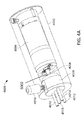
Referring now to FIG. 1 and FIGS. 3A through 3D , in an embodiment, a jet distributor is provided to supply fluids to each of the side jet openings, such as 605 a, 605 b, 610 a, 610 b in the multi jet endoscope tip 6501 of FIGS. 3A through 3D , and the front jet 344. The jet distributor typically comprises three fluid channels to provide fluid to the front jet 344, right- side jets 605 a, 610 a and left-side- jets 605 b, 610 b in the endoscope tip 6501. FIG. 4A illustrates a multi jet distributor 4000, in accordance with an embodiment of the present specification. As illustrated, the multi jet distributor 4000 comprises a distributor motor housing 4002 and a distributor motor 4004 coupled with a motor shaft 4006 which in turn is coupled with a distributor rotating plug 5002 placed inside a distributor disc or cap 4008 adapted to channel fluid out into three exiting fluid pipelines 4010, 4012, and 4014, thereby supplying fluid to three jet openings (front jet 344, right-side- jets 605 a, 610 a and left-side- jets 605 b, 610 b) in the endoscope tip. The multi jet distributor 4000 further comprises an entering fluid pipeline 4016 that transports fluid from a fluid source, via a conventional jet pump, into the multi-jet distributor 4000. Locking element 4018 enables the distributor disc 4008 to be latched on to the motor shaft 4006. In various embodiments, different fluid distribution rates can be selected by varying the electric current applied to the distributor motor.
In one embodiment, jet distributor 4000 comprises two fluid channels to provide fluid to the front jet 344 and sides jets 605 a, 605 b, 610 a, 610 b in the endoscope tip. The multi jet distributor 4000 comprises a distributor motor housing 4002 and a distributor motor 4004 coupled with a motor shaft 4006 which, in turn, is coupled with a distributor disc 4008 adapted to channel fluid out into two exiting fluid pipelines, thereby supplying fluid to three jet openings in the endoscope tip. In this embodiment, the two sides jets are fed by a common jet channel split into two pipelines upon entering the endoscope tip; one provides fluids to the right-side-jets and the other to the left-side-jets.
In one embodiment, the distributor disc 4008 is a substantially cylindrical structure comprising a plurality of circular slots for attaching with fluid pipelines. In an embodiment, the distributor disc 4008 comprises a slot for attaching with an entering fluid pipeline 4016 which has a diameter ranging from approximately 1 to 20 millimeters, and more specifically between 1 to 10 millimeters. In an embodiment, the distributor disc 4008 further comprises at least two slots for attaching with exiting fluid pipelines, each having a diameter ranging from approximately 1 to 20 millimeters, and more specifically between 1 to 10 millimeters. The circular slots on the face of the distributor disc 4008 attaching with the fluid pipelines are separated by a minimum distance. In an embodiment, the length of the entering and exiting pipelines is selected to minimize the overall space requirements of the distributor pump, yet achieve the fluid rate objectives of the present invention as described below. Also, in an embodiment, the fluid pipelines are connected to the distributor disc 4008 by using sealing members such as an O-ring or a gasket. During use, fluid pipelines are threaded and secured via threading onto the distributor disc 4008 and sealed thereto, using the sealing members. In an embodiment, the three exit pipelines connect to, or mate with, complementary fluid channels, which direct fluid through to the jet openings in the endoscope tip, via a main connector. In an embodiment, a universal luer connector is used to connect the fluid pipelines to the main connector. In other embodiments, any suitable connecting element may be used to connect the fluid pipelines to the main connector.
Three of the pipes which are positioned normal to the face of the distributor disc are exiting fluid pipelines 4010, 4012, and 4014 and operate to supply fluid to three jet openings in an endoscope tip. The fourth pipe which is positioned normal to the face of the distributor disc is an entering fluid pipeline 4016.
In various embodiments, a distributor rate within the multi jet distributor 4000 can vary from 30 revolutions per minute (rpm) to 100 rpm, and more specifically between 50-65 rpm. The distributor rate may also depend upon a fluid flow rate received into the multi jet distributor.
The distributor rate is defined as the revolutions per minute (rpm) of a distributor rotating plug contained within the distributor disc or cap and attached to the motor shaft, as described with reference to FIGS. 7A and 7B below.
In an embodiment, a first pipeline supplies fluid to a front panel of the endoscope, a second pipeline supplies fluid to one side of the tip, and a third pipeline supplies fluid to the other side of the tip. In another embodiment, only two pipelines enter the main connector, wherein a first pipeline supplies fluid to the front jet and a second supplies fluid to the side jets of the endoscope.
In various embodiments, in order to activate the jet and wash a lumen in a patient's body, a doctor/physician operating the endoscope is required to push a button located either on a handle of the endoscope, on the main control unit, or on a control panel of the endoscope. Once the button is pressed, the multi jet distributor starts providing fluid at a pre-determined rate to each of the three fluid channels of the endoscope. In another embodiment, the doctor/physician may be required to push/step on a foot pedal to activate the jet-pump, which is in data communication with the foot pedal or other activation means. The jet-pump provides fluid to the multi jet distributor and at the same time activates the multi jet distributor motor. In various embodiments, the operating doctor/physician may change a rate of flow of fluid being supplied by the multi jet distributor dynamically during the operation.
In an embodiment, the multi jet distributor is located outside the endoscope system but is connected to a main control unit of the endoscope as illustrated in FIG. 6A . The multi jet distributor may connect to the main control unit by using a coupling system. In accordance with an embodiment of the present specification, the coupling system comprises a hanger plug and socket pair such that the hanger plug is integrally formed on a distributor disc or cap portion of the multi jet distributor while the hanger socket, to removably yet fixedly receive the hanger plug, is affixed to a side of the main control unit 6018.
In various embodiments, alternate connection systems that are easily connected/disconnected but securely fixed may be used. For example, the connection system may include a magnetic coupling pair where a first magnet is fixed to the multi-distributor jet and a second magnet, having polarity opposite to the first, is affixed to a side of the main control unit. Bringing the first magnet close to the second would result into a strong magnetic coupling to enable the multi jet distributor to be removably, yet securely, attached to the main control unit.
Additional examples may include clips, snaps, clasps, hooks, a female/male attachment pair, and other connection systems that enable removable, yet firm, coupling as would be advantageously evident to persons of ordinary skill in the art
In another embodiment, the multi jet distributor is integrated into the control unit, such that the housing of the multi jet distributor is located inside the control unit.
Fluid is pumped from the jet pump 7002 into the entering fluid pipeline 7004. The entering fluid pipeline 7004 passes through the distributor disc or cap 7006 and is in fluid communication with the L-shaped fluid pathway 7020 of the distributor element 7021 via the entrance opening 7022. As the rotating plug 5002 and distributor element are rotated within the distributor disc or cap 7006 by the motor, the L-shaped fluid pathway 7020 of the distributor element 7021 is intermittently aligned with each of the exiting fluid pipelines 7008, 7010, and 7012 (seen in FIG. 7B ). During rotation of the distributor element 7021, while one exiting fluid pathway is open, the remaining two are occluded. For example, as seen in FIG. 7A , the distributor element 7021 is positioned such that its L-shaped fluid pathway 7020 is aligned to, and in fluid communication with, exiting fluid pipeline 7008. Since the L-shaped fluid pathway 7020 is the only path for fluid to exit the distributor element 7021, exiting fluid pipelines 7010 and 7012 (seen in FIG. 7B ) are effectively closed while exiting fluid pipeline 7008 is open. In another embodiment, the rotating plug is one solid piece without a distributor element, extending into the distributor disc or cap and containing an L-shaped fluid pathway.
The above examples are merely illustrative of the many applications of the system of present invention. Although only a few embodiments of the present invention have been described herein, it should be understood that the present invention might be embodied in many other specific forms without departing from the spirit or scope of the invention. Therefore, the present examples and embodiments are to be considered as illustrative and not restrictive, and the invention may be modified within the scope of the appended claims.
Claims (13)
1. A system for distributing fluid from a source external to an endoscope into a plurality of fluid channels positioned within the endoscope, comprising:
a pump;
a fluid distributor device having a fluid input channel coupled to said pump, a distributor rotating plug and a plurality of fluid output channels, wherein said distributor rotating plug includes an internal fluid pathway, said internal fluid pathway being in fluid communication with said fluid input channel and capable of being positioned, via rotational movement of said distributor rotating plug, into a plurality of configurations wherein, when in each of said plurality of configurations, said internal fluid pathway is in fluid communication with one of said plurality of said fluid output channels and is not in fluid communication with any one of the remaining said plurality of fluid output channels;
a motor shaft coupled to said distributor rotating plug;
a motor coupled to said motor shaft, wherein, upon activating the motor, the motor causes the distributor rotating plug to rotate, thereby intermittently aligning said internal fluid pathway with each of said plurality of fluid output channels, allowing fluid to move from said fluid input channel, through the internal fluid pathway and successively into each of said plurality of fluid output channels; and
at least one endoscope connector comprising said plurality of endoscope fluid channels, wherein said plurality of endoscope fluid channels are in fluid communication with the plurality of fluid output channels.
2. The system of claim 1 , further comprising a distributing element attached to said distributor rotating plug and rotatably movable within said fluid distributor device, wherein said distributing element comprises said internal fluid pathway.
3. The system of claim 1 , further comprising a housing, wherein said housing comprises said fluid distributor device, said motor and said motor shaft.
4. The system of claim 3 , wherein the housing further comprises a locking element for fixedly positioning the fluid distributor device within the housing.
5. The system of claim 4 , wherein the fluid distributor device further comprises a groove on an outer surface of said fluid distributor device for receiving the locking element.
6. The system of claim 1 , wherein the fluid distributor device is substantially cylindrical.
7. The system of claim 1 , wherein the fluid distributor device comprises a housing having an external surface and wherein each of the plurality of fluid output channels extends outward from said external surface.
8. The system of claim 1 , wherein the fluid distributor device comprises at least three fluid output channels and wherein each of said at least three fluid output channels is separately and individually connected to at least three endoscope fluid channels.
9. The system of claim 1 , wherein said at least one endoscope connector is positioned within said endoscope.
10. The system of claim 1 , wherein said at least one endoscope connector is positioned within a main control unit external to said endoscope.
11. The system of claim 10 , wherein said at least one endoscope connector comprises a plurality of connectors for connecting said plurality of endoscope fluid channels with said plurality of fluid output channels.
12. The system of claim 10 , wherein said at least one endoscope connector comprises a single connector for connecting said plurality of endoscope fluid channels with said plurality of fluid output channels.
13. The system of claim 1 , wherein said distributor rotating plug has a distributor rate ranging between 30 revolutions per minute (rpm) and 100 rpm.
Priority Applications (5)
| Application Number | Priority Date | Filing Date | Title |
|---|---|---|---|
| US14/317,863 US9636003B2 (en) | 2013-06-28 | 2014-06-27 | Multi-jet distributor for an endoscope |
| US15/439,782 US10595714B2 (en) | 2013-03-28 | 2017-02-22 | Multi-jet controller for an endoscope |
| US15/464,702 US10105039B2 (en) | 2013-06-28 | 2017-03-21 | Multi-jet distributor for an endoscope |
| US16/743,717 US11375885B2 (en) | 2013-03-28 | 2020-01-15 | Multi-jet controller for an endoscope |
| US17/837,217 US20220296086A1 (en) | 2013-03-28 | 2022-06-10 | Multi-jet controller for an endoscope |
Applications Claiming Priority (2)
| Application Number | Priority Date | Filing Date | Title |
|---|---|---|---|
| US201361840706P | 2013-06-28 | 2013-06-28 | |
| US14/317,863 US9636003B2 (en) | 2013-06-28 | 2014-06-27 | Multi-jet distributor for an endoscope |
Related Parent Applications (1)
| Application Number | Title | Priority Date | Filing Date |
|---|---|---|---|
| US14/229,699 Continuation-In-Part US9642513B2 (en) | 2009-06-18 | 2014-03-28 | Compact multi-viewing element endoscope system |
Related Child Applications (3)
| Application Number | Title | Priority Date | Filing Date |
|---|---|---|---|
| US14/469,501 Continuation-In-Part US9993142B2 (en) | 2013-03-28 | 2014-08-26 | Fluid distribution device for a multiple viewing elements endoscope |
| US15/439,782 Continuation-In-Part US10595714B2 (en) | 2013-03-28 | 2017-02-22 | Multi-jet controller for an endoscope |
| US15/464,702 Continuation US10105039B2 (en) | 2013-06-28 | 2017-03-21 | Multi-jet distributor for an endoscope |
Publications (2)
| Publication Number | Publication Date |
|---|---|
| US20150005581A1 US20150005581A1 (en) | 2015-01-01 |
| US9636003B2 true US9636003B2 (en) | 2017-05-02 |
Family
ID=52116249
Family Applications (2)
| Application Number | Title | Priority Date | Filing Date |
|---|---|---|---|
| US14/317,863 Active 2035-10-03 US9636003B2 (en) | 2013-03-28 | 2014-06-27 | Multi-jet distributor for an endoscope |
| US15/464,702 Expired - Fee Related US10105039B2 (en) | 2013-06-28 | 2017-03-21 | Multi-jet distributor for an endoscope |
Family Applications After (1)
| Application Number | Title | Priority Date | Filing Date |
|---|---|---|---|
| US15/464,702 Expired - Fee Related US10105039B2 (en) | 2013-06-28 | 2017-03-21 | Multi-jet distributor for an endoscope |
Country Status (1)
| Country | Link |
|---|---|
| US (2) | US9636003B2 (en) |
Families Citing this family (30)
| Publication number | Priority date | Publication date | Assignee | Title |
|---|---|---|---|---|
| US10524645B2 (en) | 2009-06-18 | 2020-01-07 | Endochoice, Inc. | Method and system for eliminating image motion blur in a multiple viewing elements endoscope |
| US10130246B2 (en) | 2009-06-18 | 2018-11-20 | Endochoice, Inc. | Systems and methods for regulating temperature and illumination intensity at the distal tip of an endoscope |
| US9474440B2 (en) | 2009-06-18 | 2016-10-25 | Endochoice, Inc. | Endoscope tip position visual indicator and heat management system |
| US9706908B2 (en) | 2010-10-28 | 2017-07-18 | Endochoice, Inc. | Image capture and video processing systems and methods for multiple viewing element endoscopes |
| US10663714B2 (en) | 2010-10-28 | 2020-05-26 | Endochoice, Inc. | Optical system for an endoscope |
| US10517464B2 (en) | 2011-02-07 | 2019-12-31 | Endochoice, Inc. | Multi-element cover for a multi-camera endoscope |
| US9636003B2 (en) | 2013-06-28 | 2017-05-02 | Endochoice, Inc. | Multi-jet distributor for an endoscope |
| US10595714B2 (en) | 2013-03-28 | 2020-03-24 | Endochoice, Inc. | Multi-jet controller for an endoscope |
| EP2994034B1 (en) | 2013-05-07 | 2020-09-16 | EndoChoice, Inc. | White balance enclosure for use with a multi-viewing elements endoscope |
| US9949623B2 (en) | 2013-05-17 | 2018-04-24 | Endochoice, Inc. | Endoscope control unit with braking system |
| US10064541B2 (en) | 2013-08-12 | 2018-09-04 | Endochoice, Inc. | Endoscope connector cover detection and warning system |
| US9943218B2 (en) | 2013-10-01 | 2018-04-17 | Endochoice, Inc. | Endoscope having a supply cable attached thereto |
| US9968242B2 (en) | 2013-12-18 | 2018-05-15 | Endochoice, Inc. | Suction control unit for an endoscope having two working channels |
| WO2015112747A2 (en) | 2014-01-22 | 2015-07-30 | Endochoice, Inc. | Image capture and video processing systems and methods for multiple viewing element endoscopes |
| US11234581B2 (en) | 2014-05-02 | 2022-02-01 | Endochoice, Inc. | Elevator for directing medical tool |
| CN111436896A (en) | 2014-07-21 | 2020-07-24 | 恩多巧爱思股份有限公司 | Multi-focus and multi-camera endoscope system |
| US10542877B2 (en) | 2014-08-29 | 2020-01-28 | Endochoice, Inc. | Systems and methods for varying stiffness of an endoscopic insertion tube |
| US10123684B2 (en) | 2014-12-18 | 2018-11-13 | Endochoice, Inc. | System and method for processing video images generated by a multiple viewing elements endoscope |
| US10271713B2 (en) | 2015-01-05 | 2019-04-30 | Endochoice, Inc. | Tubed manifold of a multiple viewing elements endoscope |
| US10376181B2 (en) | 2015-02-17 | 2019-08-13 | Endochoice, Inc. | System for detecting the location of an endoscopic device during a medical procedure |
| DE102015203429A1 (en) * | 2015-02-26 | 2016-09-01 | Olympus Winter & Ibe Gmbh | Fluid distributor for a treatment device for surgical instruments |
| US10078207B2 (en) | 2015-03-18 | 2018-09-18 | Endochoice, Inc. | Systems and methods for image magnification using relative movement between an image sensor and a lens assembly |
| US10401611B2 (en) | 2015-04-27 | 2019-09-03 | Endochoice, Inc. | Endoscope with integrated measurement of distance to objects of interest |
| EP3297515B1 (en) | 2015-05-17 | 2020-07-01 | Endochoice, Inc. | Endoscopic image enhancement using contrast limited adaptive histogram equalization (clahe) implemented in a processor |
| CN108430373B (en) | 2015-10-28 | 2022-05-27 | 安多卓思公司 | Apparatus and method for tracking the position of an endoscope within a patient |
| CN113425225A (en) | 2015-11-24 | 2021-09-24 | 安多卓思公司 | Disposable air/water and suction valve for endoscope |
| US10488648B2 (en) | 2016-02-24 | 2019-11-26 | Endochoice, Inc. | Circuit board assembly for a multiple viewing element endoscope using CMOS sensors |
| WO2017160792A1 (en) | 2016-03-14 | 2017-09-21 | Endochoice, Inc. | System and method for guiding and tracking a region of interest using an endoscope |
| CN109475275B (en) | 2016-05-23 | 2022-04-08 | 安多卓思公司 | Multi-nozzle controller for endoscope |
| JP7000353B2 (en) | 2016-06-21 | 2022-01-19 | エンドチョイス インコーポレイテッド | Endoscope system with multiple connection interfaces to interface with different video data signal sources |
Citations (8)
| Publication number | Priority date | Publication date | Assignee | Title |
|---|---|---|---|---|
| US5630798A (en) * | 1991-08-21 | 1997-05-20 | Smith & Nephew Dyonics Inc. | Fluid management system |
| US5685821A (en) * | 1992-10-19 | 1997-11-11 | Arthrotek | Method and apparatus for performing endoscopic surgical procedures |
| US5810770A (en) * | 1996-12-13 | 1998-09-22 | Stryker Corporation | Fluid management pump system for surgical procedures |
| US6095971A (en) * | 1997-10-22 | 2000-08-01 | Fuji Photo Optical Co., Ltd. | Endoscope fluid controller |
| US20070100206A1 (en) * | 2005-10-31 | 2007-05-03 | Szu-Min Lin | Apparatus and method for providing flow to endoscope channels |
| US20070118015A1 (en) * | 2000-01-27 | 2007-05-24 | Wendlandt Jeffrey M | Catheter introducer system for exploration of body cavities |
| US8353860B2 (en) * | 2004-09-30 | 2013-01-15 | Boston Scientific Scimed, Inc. | Device for obstruction removal with specific tip structure |
| US9289110B2 (en) * | 2012-04-05 | 2016-03-22 | Stryker Corporation | Control for surgical fluid management pump system |
Family Cites Families (383)
| Publication number | Priority date | Publication date | Assignee | Title |
|---|---|---|---|---|
| US3639714A (en) | 1970-05-15 | 1972-02-01 | Fujisoku Electric | Pushbutton alternate action switch with pushbutton shaft unconnected to alternate action actuator block |
| US3955064A (en) | 1974-05-23 | 1976-05-04 | Le Salon Bruno Demetrio Ltd. | Hair styling iron having interchangeable heating tips |
| US4084401A (en) | 1975-07-09 | 1978-04-18 | Hughes Aircraft Company | Digital watch with two buttons and improved setting and display control |
| US4037588A (en) | 1975-09-11 | 1977-07-26 | Richard Wolf Gmbh | Laryngoscopes |
| US4027697A (en) | 1975-11-19 | 1977-06-07 | Bonney Roland W | Rotary valve |
| JPS54144787A (en) | 1978-05-02 | 1979-11-12 | Ouchi Teruo | Device for curving endoscope |
| JPS5675133A (en) | 1979-11-22 | 1981-06-22 | Olympus Optical Co | Light source apparatus for endoscope |
| JPS57192547A (en) | 1981-05-21 | 1982-11-26 | Olympus Optical Co | Ultrasonic diagnostic apparatus for body cavity |
| US4532918A (en) | 1983-10-07 | 1985-08-06 | Welch Allyn Inc. | Endoscope signal level control |
| JPS60263916A (en) | 1984-06-13 | 1985-12-27 | Olympus Optical Co Ltd | Retrofocus type varifocal objective lens for endoscope |
| US4588294A (en) | 1984-06-27 | 1986-05-13 | Warner-Lambert Technologies, Inc. | Searching and measuring endoscope |
| US4641635A (en) | 1984-08-15 | 1987-02-10 | Olympus Optical Co., Ltd. | Endoscope apparatus |
| JPS62220918A (en) | 1986-03-22 | 1987-09-29 | Olympus Optical Co Ltd | Endoscope optical system |
| JPH07119893B2 (en) | 1986-09-22 | 1995-12-20 | オリンパス光学工業株式会社 | Endoscope optical system |
| US4727859A (en) | 1986-12-29 | 1988-03-01 | Welch Allyn, Inc. | Right angle detachable prism assembly for borescope |
| JP2697822B2 (en) | 1987-05-25 | 1998-01-14 | オリンパス光学工業株式会社 | Endoscope objective lens |
| JP2804267B2 (en) | 1988-05-02 | 1998-09-24 | オリンパス光学工業株式会社 | Endoscope objective lens |
| US4825850A (en) | 1988-05-13 | 1989-05-02 | Opielab, Inc. | Contamination protection system for endoscope control handles |
| JPH0223931A (en) | 1988-07-13 | 1990-01-26 | Asahi Optical Co Ltd | Brake means of curving device of endoscope |
| JPH07122692B2 (en) | 1988-09-29 | 1995-12-25 | 富士写真光機株式会社 | Objective lens for endoscope |
| US5007406A (en) | 1988-11-04 | 1991-04-16 | Asahi Kogaku Kogyo Kabushiki Kaisha | Bending control device of endoscope |
| US5193525A (en) | 1990-11-30 | 1993-03-16 | Vision Sciences | Antiglare tip in a sheath for an endoscope |
| US5224929A (en) | 1990-12-21 | 1993-07-06 | C. R. Bard, Inc. | Irrigation/aspiration cannula and valve assembly |
| JPH0827429B2 (en) | 1991-03-04 | 1996-03-21 | オリンパス光学工業株式会社 | Objective lens for endoscope |
| US5359456A (en) | 1991-10-15 | 1994-10-25 | Olympus Optical Co., Ltd. | Objective lens system for endoscopes |
| CA2143639C (en) | 1992-09-01 | 2004-07-20 | Edwin L. Adair | Sterilizable endoscope with separable disposable tube assembly |
| US5630782A (en) | 1992-09-01 | 1997-05-20 | Adair; Edwin L. | Sterilizable endoscope with separable auxiliary assembly |
| US5836894A (en) | 1992-12-21 | 1998-11-17 | Artann Laboratories | Apparatus for measuring mechanical parameters of the prostate and for imaging the prostate using such parameters |
| JP3372980B2 (en) | 1993-01-22 | 2003-02-04 | オリンパス光学工業株式会社 | Endoscope |
| US5863286A (en) | 1993-01-27 | 1999-01-26 | Olympus Optical Company, Ltd. | Endoscope system including endoscope and disposable protection cover |
| US5674182A (en) | 1993-02-26 | 1997-10-07 | Olympus Optical Co., Ltd. | Endoscope system including endoscope and protection cover |
| US5460167A (en) | 1993-03-04 | 1995-10-24 | Olympus Optical Co., Ltd. | Endoscope cover with channel |
| US5569157A (en) | 1993-05-07 | 1996-10-29 | Olympus Optical Co., Ltd. | Endoscope |
| US5475420A (en) | 1993-06-09 | 1995-12-12 | Origin Medsystems, Inc. | Video imaging system with image processing optimized for small-diameter endoscopes |
| US5447148A (en) | 1993-07-08 | 1995-09-05 | Vision Sciences, Inc. | Endoscopic contamination protection system to facilitate cleaning of endoscopes |
| US5830121A (en) | 1993-10-27 | 1998-11-03 | Asahi Kogaku Kogyo Kabushiki Kaisha | Endoscopic apparatus having an endoscope and a peripheral device wherein total usage of the endoscope is quantified and recorded |
| JP3392920B2 (en) | 1993-11-26 | 2003-03-31 | ペンタックス株式会社 | Endoscope tip |
| US5746695A (en) | 1993-11-18 | 1998-05-05 | Asahi Kogaku Kogyo Kabushiki Kaisha | Front end structure of endoscope |
| JP3272516B2 (en) | 1993-11-18 | 2002-04-08 | 旭光学工業株式会社 | Endoscope tip |
| DE69426057T2 (en) | 1993-11-29 | 2001-05-10 | Olympus Optical Co | Arrangement for image rotation and overlay |
| US5395329A (en) | 1994-01-19 | 1995-03-07 | Daig Corporation | Control handle for steerable catheter |
| US5575755A (en) | 1994-02-23 | 1996-11-19 | Welch Allyn, Inc. | Fluid insensitive braking for an endoscope |
| US5464007A (en) | 1994-02-23 | 1995-11-07 | Welch Allyn, Inc. | Fluid insensitive braking for an endoscope |
| US5547455A (en) | 1994-03-30 | 1996-08-20 | Medical Media Systems | Electronically steerable endoscope |
| US5685823A (en) | 1994-03-30 | 1997-11-11 | Asahi Kogaku Kogyo Kabushiki Kaisha | End structure of endoscope |
| US5782751A (en) | 1994-05-26 | 1998-07-21 | Asahi Kogaku Kogyo Kabushiki Kaisha | Side view endoscope |
| JP3379821B2 (en) | 1994-05-31 | 2003-02-24 | オリンパス光学工業株式会社 | Endoscope |
| US5518502A (en) | 1994-06-08 | 1996-05-21 | The United States Surgical Corporation | Compositions, methods and apparatus for inhibiting fogging of endoscope lenses |
| JP3051035B2 (en) | 1994-10-18 | 2000-06-12 | 富士写真光機株式会社 | Objective lens for endoscope |
| US5940126A (en) | 1994-10-25 | 1999-08-17 | Kabushiki Kaisha Toshiba | Multiple image video camera apparatus |
| JPH0910170A (en) | 1995-06-29 | 1997-01-14 | Olympus Optical Co Ltd | Objective optical system of endoscope |
| JPH0980305A (en) | 1995-09-11 | 1997-03-28 | Fuji Photo Optical Co Ltd | Endoscope objective lens |
| US5810717A (en) | 1995-09-22 | 1998-09-22 | Mitsubishi Cable Industries, Ltd. | Bending mechanism and stereoscope using same |
| US5810715A (en) | 1995-09-29 | 1998-09-22 | Olympus Optical Co., Ltd. | Endoscope provided with function of being locked to flexibility of insertion part which is set by flexibility modifying operation member |
| US6117068A (en) | 1995-10-19 | 2000-09-12 | Elite Genetics, Inc | Artificial insemination system |
| US5725478A (en) | 1996-03-14 | 1998-03-10 | Saad; Saad A. | Methods and apparatus for providing suction and/or irrigation in a rigid endoscope while maintaining visual contact with a target area through the endoscope |
| US5860913A (en) | 1996-05-16 | 1999-01-19 | Olympus Optical Co., Ltd. | Endoscope whose distal cover can be freely detachably attached to main distal part thereof with high positioning precision |
| JPH1043129A (en) | 1996-08-02 | 1998-02-17 | Olympus Optical Co Ltd | Endoscope |
| US7018331B2 (en) | 1996-08-26 | 2006-03-28 | Stryker Corporation | Endoscope assembly useful with a scope-sensing light cable |
| DE19636152C2 (en) | 1996-09-06 | 1999-07-01 | Schneider Co Optische Werke | Compact wide angle lens |
| JP4054094B2 (en) | 1996-12-27 | 2008-02-27 | オリンパス株式会社 | Electronic endoscope |
| AUPO478397A0 (en) | 1997-01-31 | 1997-02-20 | Fairmont Medical Products Pty Ltd | Endoscopic drape |
| US6058109A (en) | 1997-02-04 | 2000-05-02 | The Kohl Group, Inc. | Combined uniform rate and burst rate transmission system |
| US6095970A (en) | 1997-02-19 | 2000-08-01 | Asahi Kogaku Kogyo Kabushiki Kaisha | Endoscope |
| JPH10239740A (en) | 1997-02-28 | 1998-09-11 | Toshiba Corp | Endoscope device |
| US5924976A (en) | 1997-08-21 | 1999-07-20 | Stelzer; Paul | Minimally invasive surgery device |
| US20040052076A1 (en) | 1997-08-26 | 2004-03-18 | Mueller George G. | Controlled lighting methods and apparatus |
| KR20010023427A (en) | 1997-08-28 | 2001-03-26 | 퀼리아 컴퓨팅 인코포레이티드 | Method and system for automated detection of clustered microcalcifications from digital mammograms |
| US20110034769A1 (en) | 1997-10-06 | 2011-02-10 | Micro-Imaging Solutions Llc | Reduced area imaging device incorporated within wireless endoscopic devices |
| JPH11137512A (en) | 1997-11-07 | 1999-05-25 | Toshiba Corp | Endoscopic equipment |
| US7598686B2 (en) | 1997-12-17 | 2009-10-06 | Philips Solid-State Lighting Solutions, Inc. | Organic light emitting diode methods and apparatus |
| US6277064B1 (en) | 1997-12-30 | 2001-08-21 | Inbae Yoon | Surgical instrument with rotatably mounted offset endoscope |
| US6196967B1 (en) | 1998-03-18 | 2001-03-06 | Linvatec Corporation | Arthroscopic component joining system |
| US6419626B1 (en) | 1998-08-12 | 2002-07-16 | Inbae Yoon | Surgical instrument endoscope with CMOS image sensor and physical parameter sensor |
| JP4014186B2 (en) | 1998-11-30 | 2007-11-28 | フジノン株式会社 | Endoscope objective lens |
| JP3704248B2 (en) | 1999-02-04 | 2005-10-12 | ペンタックス株式会社 | Endoscope operation wire connection structure |
| US7015950B1 (en) | 1999-05-11 | 2006-03-21 | Pryor Timothy R | Picture taking method and apparatus |
| JP4245731B2 (en) | 1999-06-08 | 2009-04-02 | オリンパス株式会社 | Liquid crystal lens unit and liquid crystal lens assembly |
| US6690337B1 (en) | 1999-06-09 | 2004-02-10 | Panoram Technologies, Inc. | Multi-panel video display |
| IL143258A0 (en) | 2001-05-20 | 2002-04-21 | Given Imaging Ltd | A method for in vivo imaging of the gastrointestinal tract in unmodified conditions |
| US20020087047A1 (en) | 1999-09-13 | 2002-07-04 | Visionscope, Inc. | Miniature endoscope system |
| JP2001095747A (en) | 1999-09-30 | 2001-04-10 | Olympus Optical Co Ltd | Electronic endoscope |
| JP2001177824A (en) | 1999-12-17 | 2001-06-29 | Asahi Optical Co Ltd | Signal changeover device for electronic endoscope |
| WO2001069919A1 (en) | 2000-03-10 | 2001-09-20 | Datacube, Inc. | Image processing system using an array processor |
| IL138632A (en) | 2000-09-21 | 2008-06-05 | Minelu Zonnenschein | Multiple view endoscopes |
| US6837846B2 (en) | 2000-04-03 | 2005-01-04 | Neo Guide Systems, Inc. | Endoscope having a guide tube |
| US6712760B2 (en) | 2000-04-10 | 2004-03-30 | Pentax Corporation | Television device of portable endoscope |
| US6673012B2 (en) | 2000-04-19 | 2004-01-06 | Pentax Corporation | Control device for an endoscope |
| US20010055062A1 (en) | 2000-04-20 | 2001-12-27 | Keiji Shioda | Operation microscope |
| US6821245B2 (en) | 2000-07-14 | 2004-11-23 | Xillix Technologies Corporation | Compact fluorescence endoscopy video system |
| JP3945133B2 (en) | 2000-08-02 | 2007-07-18 | フジノン株式会社 | Endoscope observation window cleaning device |
| US6717092B2 (en) | 2000-08-11 | 2004-04-06 | Pentax Corporation | Method of manufacturing treatment instrument of endoscope |
| ATE523034T1 (en) | 2001-01-16 | 2011-09-15 | Given Imaging Ltd | SYSTEM AND METHOD FOR WIDE-ANGLE IMAGING OF BODY LUMENS |
| US6743168B2 (en) | 2001-02-02 | 2004-06-01 | Insight Instruments, Inc. | Endoscope system and method of use |
| JP3939158B2 (en) | 2001-02-06 | 2007-07-04 | オリンパス株式会社 | Endoscope device |
| US20020109771A1 (en) | 2001-02-14 | 2002-08-15 | Michael Ledbetter | Method and system for videoconferencing |
| JP2002263055A (en) | 2001-03-12 | 2002-09-17 | Olympus Optical Co Ltd | Tip hood for endoscope |
| DE10121450A1 (en) | 2001-04-27 | 2002-11-21 | Storz Endoskop Gmbh Schaffhaus | Optical instrument, in particular an endoscope, with an exchangeable head |
| US6618205B2 (en) | 2001-05-14 | 2003-09-09 | Pentax Corporation | Endoscope objective optical system |
| DE60228165D1 (en) | 2001-05-16 | 2008-09-25 | Olympus Corp | Endoscope with image processing device |
| US7231135B2 (en) | 2001-05-18 | 2007-06-12 | Pentax Of American, Inc. | Computer-based video recording and management system for medical diagnostic equipment |
| US7123288B2 (en) | 2001-09-28 | 2006-10-17 | Fujinon Corporation | Electronic endoscope eliminating influence of light distribution in optical zooming |
| US6980227B2 (en) | 2001-10-01 | 2005-12-27 | Pentax Corporation | Electronic endoscope with light-amount adjustment apparatus |
| US6863651B2 (en) | 2001-10-19 | 2005-03-08 | Visionscope, Llc | Miniature endoscope with imaging fiber system |
| US8038602B2 (en) | 2001-10-19 | 2011-10-18 | Visionscope Llc | Portable imaging system employing a miniature endoscope |
| US20070167681A1 (en) | 2001-10-19 | 2007-07-19 | Gill Thomas J | Portable imaging system employing a miniature endoscope |
| EP1313066B1 (en) | 2001-11-19 | 2008-08-27 | STMicroelectronics S.r.l. | A method for merging digital images to obtain a high dynamic range digital image |
| AU2002366985A1 (en) | 2001-12-26 | 2003-07-30 | Yeda Research And Development Co.Ltd. | A system and method for increasing space or time resolution in video |
| US20030158503A1 (en) | 2002-01-18 | 2003-08-21 | Shinya Matsumoto | Capsule endoscope and observation system that uses it |
| JP4147033B2 (en) | 2002-01-18 | 2008-09-10 | オリンパス株式会社 | Endoscope device |
| US20030153897A1 (en) | 2002-02-12 | 2003-08-14 | Russo Ronald D. | Closed system drainage and infusion connector valve |
| US8988599B2 (en) | 2010-08-31 | 2015-03-24 | University Of Southern California | Illumination sphere with intelligent LED lighting units in scalable daisy chain with interchangeable filters |
| JP4170685B2 (en) | 2002-07-05 | 2008-10-22 | フジノン株式会社 | Endoscope bending operation mechanism |
| AU2003274984A1 (en) | 2002-09-13 | 2004-04-30 | Karl Storz Imaging, Inc. | Video recording and image capture device |
| US20040061780A1 (en) | 2002-09-13 | 2004-04-01 | Huffman David A. | Solid-state video surveillance system |
| JP4131012B2 (en) | 2002-10-10 | 2008-08-13 | Hoya株式会社 | Endoscope with sheath |
| US7097632B2 (en) | 2002-10-28 | 2006-08-29 | Sherwood Services Ag | Automatic valve |
| US7537561B2 (en) | 2002-11-27 | 2009-05-26 | Olympus Corporation | Endoscope apparatus |
| FR2857200B1 (en) | 2003-07-01 | 2005-09-30 | Tokendo | VIDEO PROCESSOR FOR ENDOSCOPY |
| DE102004006541B4 (en) | 2003-02-10 | 2016-11-10 | Hoya Corp. | endoscope |
| US7027231B2 (en) | 2003-02-14 | 2006-04-11 | Fujinon Corporation | Endoscope objective lens |
| US7160249B2 (en) | 2003-03-28 | 2007-01-09 | Olympus Corporation | Endoscope image pickup unit for picking up magnified images of an object, a focus adjustment apparatus and method, and a focus range check apparatus and method for the same |
| US20050222499A1 (en) | 2003-04-01 | 2005-10-06 | Banik Michael S | Interface for video endoscope system |
| US8118732B2 (en) | 2003-04-01 | 2012-02-21 | Boston Scientific Scimed, Inc. | Force feedback control system for video endoscope |
| ATE553690T1 (en) | 2003-05-01 | 2012-05-15 | Given Imaging Ltd | PANORAMA FIELD OF VIEW DISPLAY DEVICE |
| JP4144444B2 (en) | 2003-06-20 | 2008-09-03 | フジノン株式会社 | Endoscope fluid delivery device |
| US7153259B2 (en) | 2003-09-01 | 2006-12-26 | Olympus Corporation | Capsule type endoscope |
| US7154378B1 (en) | 2003-09-11 | 2006-12-26 | Stryker Corporation | Apparatus and method for using RFID to track use of a component within a device |
| JP4533695B2 (en) | 2003-09-23 | 2010-09-01 | オリンパス株式会社 | Treatment endoscope |
| US20050251127A1 (en) | 2003-10-15 | 2005-11-10 | Jared Brosch | Miniature ultrasonic transducer with focusing lens for intracardiac and intracavity applications |
| EP1685790A1 (en) | 2003-11-14 | 2006-08-02 | Apricot Co., Ltd. | Endoscope device and imaging method using the same |
| EP1690497B1 (en) | 2003-12-02 | 2017-02-22 | Olympus Corporation | Ultrasonographic device |
| EP1707102B1 (en) | 2004-01-19 | 2010-05-05 | Olympus Corporation | Capsule type medical treatment device |
| WO2005067783A1 (en) | 2004-01-19 | 2005-07-28 | Olympus Corporation | Imaging device for endoscope and capsule type endoscope |
| JP4448348B2 (en) | 2004-03-10 | 2010-04-07 | Hoya株式会社 | Endoscope water channel |
| ES2409160T3 (en) | 2004-03-23 | 2013-06-25 | Boston Scientific Limited | Live View System |
| JP2005278762A (en) | 2004-03-29 | 2005-10-13 | Fujinon Corp | Centesis type probe for endoscope |
| US7976462B2 (en) | 2004-04-06 | 2011-07-12 | Integrated Endoscopy, Inc. | Endoscope designs and methods of manufacture |
| US8277373B2 (en) | 2004-04-14 | 2012-10-02 | Usgi Medical, Inc. | Methods and apparaus for off-axis visualization |
| US20050272977A1 (en) | 2004-04-14 | 2005-12-08 | Usgi Medical Inc. | Methods and apparatus for performing endoluminal procedures |
| US8512229B2 (en) | 2004-04-14 | 2013-08-20 | Usgi Medical Inc. | Method and apparatus for obtaining endoluminal access |
| JP4500096B2 (en) | 2004-04-27 | 2010-07-14 | オリンパス株式会社 | Endoscope and endoscope system |
| JP3967337B2 (en) | 2004-05-14 | 2007-08-29 | オリンパス株式会社 | Endoscope and endoscope apparatus |
| US20050277808A1 (en) | 2004-05-14 | 2005-12-15 | Elazar Sonnenschein | Methods and devices related to camera connectors |
| WO2005112737A1 (en) | 2004-05-24 | 2005-12-01 | Olympus Corporation | Light source device for endoscope |
| IL162390A0 (en) | 2004-06-07 | 2005-11-20 | Medigus Ltd | Multipurpose endoscopy suite |
| US8500630B2 (en) | 2004-06-30 | 2013-08-06 | Given Imaging Ltd. | In vivo device with flexible circuit board and method for assembly thereof |
| JP4779120B2 (en) | 2004-07-02 | 2011-09-28 | 国立大学法人大阪大学 | Endoscope attachment and endoscope |
| JP4544924B2 (en) | 2004-07-12 | 2010-09-15 | フォルテ グロウ メディカル株式会社 | Endoscopy tube |
| US7335159B2 (en) | 2004-08-26 | 2008-02-26 | Scimed Life Systems, Inc. | Endoscope having auto-insufflation and exsufflation |
| JP4649606B2 (en) | 2004-08-31 | 2011-03-16 | 国立大学法人 名古屋工業大学 | Spherical capsule type omnidirectional endoscope |
| AU2005278773A1 (en) | 2004-09-03 | 2006-03-09 | Stryker Gi Ltd. | Optical head for endoscope |
| US8081818B2 (en) | 2004-09-15 | 2011-12-20 | Adobe Systems Incorporated | Locating a feature in a digital image |
| US8480566B2 (en) | 2004-09-24 | 2013-07-09 | Vivid Medical, Inc. | Solid state illumination for endoscopy |
| US7241263B2 (en) | 2004-09-30 | 2007-07-10 | Scimed Life Systems, Inc. | Selectively rotatable shaft coupler |
| WO2006039522A2 (en) | 2004-09-30 | 2006-04-13 | Boston Scientific Scimed, Inc. | Adapter for use with digital imaging medical device |
| US20090023998A1 (en) | 2007-07-17 | 2009-01-22 | Nitesh Ratnakar | Rear view endoscope sheath |
| US20080275298A1 (en) | 2004-10-11 | 2008-11-06 | Novation Science, Llc | Dual View Endoscope |
| US11653816B2 (en) | 2004-10-11 | 2023-05-23 | Nitesh Ratnakar | Next generation endoscope |
| US8585584B2 (en) | 2004-10-11 | 2013-11-19 | Nitesh Ratnakar | Dual view endoscope |
| US7621869B2 (en) | 2005-05-06 | 2009-11-24 | Nitesh Ratnakar | Next generation colonoscope |
| US9131861B2 (en) | 2004-11-30 | 2015-09-15 | Academisch Medisch Centrum | Pulsed lighting imaging systems and methods |
| US20060149127A1 (en) | 2004-12-30 | 2006-07-06 | Seddiqui Fred R | Disposable multi-lumen catheter with reusable stylet |
| US20080021274A1 (en) | 2005-01-05 | 2008-01-24 | Avantis Medical Systems, Inc. | Endoscopic medical device with locking mechanism and method |
| US8182422B2 (en) | 2005-12-13 | 2012-05-22 | Avantis Medical Systems, Inc. | Endoscope having detachable imaging device and method of using |
| US8289381B2 (en) | 2005-01-05 | 2012-10-16 | Avantis Medical Systems, Inc. | Endoscope with an imaging catheter assembly and method of configuring an endoscope |
| US8872906B2 (en) | 2005-01-05 | 2014-10-28 | Avantis Medical Systems, Inc. | Endoscope assembly with a polarizing filter |
| US20070293720A1 (en) | 2005-01-05 | 2007-12-20 | Avantis Medical Systems, Inc. | Endoscope assembly and method of viewing an area inside a cavity |
| US8797392B2 (en) | 2005-01-05 | 2014-08-05 | Avantis Medical Sytems, Inc. | Endoscope assembly with a polarizing filter |
| US20060149129A1 (en) | 2005-01-05 | 2006-07-06 | Watts H D | Catheter with multiple visual elements |
| US7668450B2 (en) | 2005-01-28 | 2010-02-23 | Stryker Corporation | Endoscope with integrated light source |
| US8029439B2 (en) | 2005-01-28 | 2011-10-04 | Stryker Corporation | Disposable attachable light source unit for an endoscope |
| US20060215406A1 (en) | 2005-02-18 | 2006-09-28 | William Thrailkill | Medical diagnostic instrument with highly efficient, tunable light emitting diode light source |
| EP1859723B1 (en) | 2005-03-15 | 2012-07-11 | Olympus Medical Systems Corp. | Insertion section for endoscope |
| KR100895750B1 (en) | 2005-03-18 | 2009-04-30 | 올림푸스 메디칼 시스템즈 가부시키가이샤 | Endoscope, endoscope system, and switching circuit member for endoscope |
| US8388523B2 (en) | 2005-04-01 | 2013-03-05 | Welch Allyn, Inc. | Medical diagnostic instrument having portable illuminator |
| US8092475B2 (en) | 2005-04-15 | 2012-01-10 | Integra Lifesciences (Ireland) Ltd. | Ultrasonic horn for removal of hard tissue |
| JP4754871B2 (en) | 2005-05-11 | 2011-08-24 | オリンパスメディカルシステムズ株式会社 | End of the endoscope |
| US20060293556A1 (en) | 2005-05-16 | 2006-12-28 | Garner David M | Endoscope with remote control module or camera |
| JP4987257B2 (en) | 2005-06-29 | 2012-07-25 | オリンパス株式会社 | Endoscope |
| US20070015989A1 (en) | 2005-07-01 | 2007-01-18 | Avantis Medical Systems, Inc. | Endoscope Image Recognition System and Method |
| CA2621218A1 (en) | 2005-09-06 | 2007-03-15 | Amram Aizenfeld | Disposable cap for endoscope |
| WO2007034664A1 (en) | 2005-09-22 | 2007-03-29 | Olympus Corporation | Endoscope insertion part |
| GB0519769D0 (en) | 2005-09-28 | 2005-11-09 | Imp College Innovations Ltd | Imaging system |
| US7430682B2 (en) | 2005-09-30 | 2008-09-30 | Symbol Technologies, Inc. | Processing image data from multiple sources |
| US9060678B2 (en) | 2006-06-13 | 2015-06-23 | Intuitive Surgical Operations, Inc. | Minimally invasive surgical system |
| US20070162095A1 (en) | 2006-01-06 | 2007-07-12 | Ezc Medical Llc | Modular visualization stylet apparatus and methods of use |
| JP5435957B2 (en) | 2006-01-23 | 2014-03-05 | アヴァンティス メディカル システムズ インコーポレイテッド | Endoscope |
| WO2007087421A2 (en) | 2006-01-23 | 2007-08-02 | Avantis Medical Systems, Inc. | Endoscope |
| WO2007089719A2 (en) | 2006-01-30 | 2007-08-09 | New Wave Surgical Corp. | Device for white balancing and applying an anti-fog agent to medical videoscopes prior to medical procedures |
| US20110004058A1 (en) | 2006-01-30 | 2011-01-06 | Vision - Sciences Inc. | Controllable Endoscope |
| JP5469867B2 (en) | 2006-02-06 | 2014-04-16 | アヴァンティス メディカル システムズ インコーポレイテッド | Endoscope with imaging catheter assembly and method for constructing an endoscope |
| EP2520218A1 (en) | 2006-02-09 | 2012-11-07 | Avantis Medical Systems, Inc. | Endoscope assembly with a polarizing filter |
| DE102007038859B4 (en) | 2006-02-23 | 2020-03-12 | Atmos Medizintechnik Gmbh & Co. Kg | Method and arrangement for generating a signal according to patent DE 10 2006 008 990 B4 corresponding to the opening state of the vocal folds of the larynx |
| WO2007100846A2 (en) | 2006-02-28 | 2007-09-07 | Emphasys Medical, Inc. | Endoscopic tool |
| US7834910B2 (en) | 2006-03-01 | 2010-11-16 | David M. DeLorme | Method and apparatus for panoramic imaging |
| US9814372B2 (en) | 2007-06-27 | 2017-11-14 | Syntheon, Llc | Torque-transmitting, variably-flexible, locking insertion device and method for operating the insertion device |
| US20070225562A1 (en) | 2006-03-23 | 2007-09-27 | Ethicon Endo-Surgery, Inc. | Articulating endoscopic accessory channel |
| US8063933B2 (en) | 2006-03-27 | 2011-11-22 | Given Imaging Ltd. | Battery contacts for an in-vivo imaging device |
| US7794393B2 (en) | 2006-04-13 | 2010-09-14 | Larsen Dane M | Resectoscopic device and method |
| US20070241895A1 (en) | 2006-04-13 | 2007-10-18 | Morgan Kelvin L | Noise reduction for flexible sensor material in occupant detection |
| US8287446B2 (en) | 2006-04-18 | 2012-10-16 | Avantis Medical Systems, Inc. | Vibratory device, endoscope having such a device, method for configuring an endoscope, and method of reducing looping of an endoscope |
| US7955255B2 (en) | 2006-04-20 | 2011-06-07 | Boston Scientific Scimed, Inc. | Imaging assembly with transparent distal cap |
| US20070247867A1 (en) | 2006-04-21 | 2007-10-25 | Sunoptic Technologies Llc | Portable LED Light Source for an Endoscope or Boroscope |
| JP4928969B2 (en) | 2006-04-26 | 2012-05-09 | Hoya株式会社 | Endoscope bending retention mechanism |
| FR2900741B1 (en) | 2006-05-05 | 2008-07-18 | Mauna Kea Technologies Soc Par | MINIATURIZED OPTICAL HEAD WITH HIGH SPACE RESOLUTION AND HIGH SENSITIVITY, ESPECIALLY FOR FIBROUS CONFOCAL FLUORESCENCE IMAGING |
| JP2007301092A (en) | 2006-05-10 | 2007-11-22 | Pentax Corp | Connector device of electronic endoscope |
| WO2007136591A1 (en) | 2006-05-15 | 2007-11-29 | Baystate Health, Inc. | Balloon endoscope device |
| JP2009537284A (en) | 2006-05-19 | 2009-10-29 | アヴァンティス メディカル システムズ インコーポレイテッド | System and method for creating and improving images |
| JP2007325724A (en) | 2006-06-07 | 2007-12-20 | Olympus Medical Systems Corp | Management system for cleaning and disinfection of endoscope |
| US20080025413A1 (en) | 2006-07-28 | 2008-01-31 | John Apostolopoulos | Selecting bit rates for encoding multiple data streams |
| EP1884805A1 (en) | 2006-08-01 | 2008-02-06 | Varioptic | Liquid lens with four liquids |
| US7927272B2 (en) | 2006-08-04 | 2011-04-19 | Avantis Medical Systems, Inc. | Surgical port with embedded imaging device |
| US20080036864A1 (en) | 2006-08-09 | 2008-02-14 | Mccubbrey David | System and method for capturing and transmitting image data streams |
| US7967745B2 (en) | 2006-09-28 | 2011-06-28 | Given Imaging, Ltd. | In vivo imaging device and method of manufacture thereof |
| US20080091065A1 (en) | 2006-10-04 | 2008-04-17 | Olympus Medical Systems Corporation | Medical image processing apparatus, endoscope system and medical image processing system |
| KR101089395B1 (en) | 2006-11-24 | 2011-12-07 | 올림푸스 메디칼 시스템즈 가부시키가이샤 | Encapsulated endoscope |
| WO2008065955A1 (en) | 2006-11-28 | 2008-06-05 | Olympus Corporation | Endoscope device |
| US7813047B2 (en) | 2006-12-15 | 2010-10-12 | Hand Held Products, Inc. | Apparatus and method comprising deformable lens element |
| JP4912141B2 (en) | 2006-12-26 | 2012-04-11 | キヤノン株式会社 | Imaging display device, imaging display control method and system |
| US20130317295A1 (en) | 2006-12-29 | 2013-11-28 | GE Inspection Technologies | Light assembly for remote visual inspection apparatus |
| US7870765B2 (en) | 2007-01-04 | 2011-01-18 | Scot Incorporated | Safing lock mechanism |
| JP5086648B2 (en) | 2007-01-19 | 2012-11-28 | オリンパスメディカルシステムズ株式会社 | Treatment tool |
| CN103222846B (en) | 2007-01-19 | 2017-04-26 | 桑尼布鲁克健康科学中心 | Scanning mechanisms for imaging probe |
| DE102007015492B4 (en) | 2007-01-30 | 2011-03-24 | Fraunhofer-Gesellschaft zur Förderung der angewandten Forschung e.V. | Illumination device for an image capture device at the distal end of an endoscope |
| US8672836B2 (en) | 2007-01-31 | 2014-03-18 | The Penn State Research Foundation | Method and apparatus for continuous guidance of endoscopy |
| WO2008093322A2 (en) | 2007-01-31 | 2008-08-07 | Stryker Gi Ltd. | Endoscope stand |
| US20090231419A1 (en) | 2007-02-06 | 2009-09-17 | Avantis Medical Systems, Inc. | Endoscope Assembly and Method of Performing a Medical Procedure |
| US20080221388A1 (en) | 2007-03-09 | 2008-09-11 | University Of Washington | Side viewing optical fiber endoscope |
| US20080246771A1 (en) | 2007-04-03 | 2008-10-09 | Dell Products L.P. | Graphics processing system and method |
| US8064666B2 (en) | 2007-04-10 | 2011-11-22 | Avantis Medical Systems, Inc. | Method and device for examining or imaging an interior surface of a cavity |
| US7813538B2 (en) | 2007-04-17 | 2010-10-12 | University Of Washington | Shadowing pipe mosaicing algorithms with application to esophageal endoscopy |
| JP2008301968A (en) | 2007-06-06 | 2008-12-18 | Olympus Medical Systems Corp | Endoscopic image processing apparatus |
| US8979738B2 (en) | 2007-06-08 | 2015-03-17 | Medeon Biosurgical, Inc. | Devices and methods for removal of debris from the objective lens of an endoscope |
| CN101686797B (en) | 2007-06-22 | 2011-11-30 | 奥林巴斯医疗株式会社 | Capsule-type medical device |
| JP2010534531A (en) | 2007-07-26 | 2010-11-11 | アヴァンティス メディカル システムズ インコーポレイテッド | Endoscope system |
| JP2009047947A (en) | 2007-08-21 | 2009-03-05 | Fujinon Corp | Imaging lens and imaging apparatus |
| CN100582855C (en) | 2007-08-23 | 2010-01-20 | 鸿富锦精密工业(深圳)有限公司 | Endoscopy lens and endoscopy device |
| JP2009056105A (en) | 2007-08-31 | 2009-03-19 | Olympus Medical Systems Corp | Focal distance variable endoscope |
| JP4904470B2 (en) | 2007-09-19 | 2012-03-28 | 富士フイルム株式会社 | Observation image forming apparatus |
| JP2009080413A (en) | 2007-09-27 | 2009-04-16 | Fujinon Corp | Imaging optical system, image pickup apparatus for endoscope |
| JP2009082504A (en) | 2007-09-28 | 2009-04-23 | Fujifilm Corp | Image pickup device and endoscope provided with image pickup device |
| WO2009049324A1 (en) | 2007-10-11 | 2009-04-16 | Avantis Medical Systems, Inc. | Method and device for reducing the fixed pattern noise of a digital image |
| EP2211683A2 (en) | 2007-10-11 | 2010-08-04 | Avantis Medical Systems, Inc. | Endoscope assembly comprising retrograde viewing imaging device and instrument channel |
| US9118850B2 (en) | 2007-11-27 | 2015-08-25 | Capso Vision, Inc. | Camera system with multiple pixel arrays on a chip |
| EP2067433B1 (en) | 2007-12-03 | 2013-05-01 | Olympus Medical Systems Corp. | Medical appliance, endoscope overtube and endoscope apparatus |
| US8360964B2 (en) | 2007-12-10 | 2013-01-29 | Stryker Corporation | Wide angle HDTV endoscope |
| US7885010B1 (en) | 2008-01-14 | 2011-02-08 | Integrated Medical Systems International | Endoscope objective lens and method of assembly |
| US8723756B2 (en) | 2008-01-15 | 2014-05-13 | Synaptics Incorporated | System having capability for daisy-chained serial distribution of video display data |
| US8529441B2 (en) | 2008-02-12 | 2013-09-10 | Innurvation, Inc. | Ingestible endoscopic optical scanning device |
| JP2009189528A (en) | 2008-02-14 | 2009-08-27 | Fujinon Corp | Processor unit for endoscope and endoscopic system |
| EP2095757A1 (en) | 2008-02-26 | 2009-09-02 | FUJIFILM Corporation | Endoscopic aspiration device |
| CN102017622B (en) | 2008-03-07 | 2015-08-26 | 密尔沃基电动工具公司 | Vision inspection apparatus |
| JP2009213673A (en) | 2008-03-11 | 2009-09-24 | Fujinon Corp | Endoscope system and endoscope inspecting method |
| WO2009117483A1 (en) | 2008-03-18 | 2009-09-24 | Novadaq Technologies Inc. | Imaging system for combined full-color reflectance and near-infrared imaging |
| ES2580177T3 (en) | 2008-05-13 | 2016-08-19 | Boston Scientific Scimed, Inc. | Steering system with locking mechanism |
| EP2241244A1 (en) | 2008-06-04 | 2010-10-20 | Fujifilm Corporation | Illumination device for use in endoscope |
| US7630148B1 (en) | 2008-06-11 | 2009-12-08 | Ge Inspection Technologies, Lp | System for providing zoom, focus and aperture control in a video inspection device |
| US8617058B2 (en) | 2008-07-09 | 2013-12-31 | Innurvation, Inc. | Displaying image data from a scanner capsule |
| JP2010017483A (en) | 2008-07-14 | 2010-01-28 | Olympus Corp | Endoscope bending tube and endoscope with bending tube |
| JP5435916B2 (en) | 2008-09-18 | 2014-03-05 | 富士フイルム株式会社 | Electronic endoscope system |
| JP5558058B2 (en) | 2008-09-19 | 2014-07-23 | オリンパスメディカルシステムズ株式会社 | Endoscopic endoscope |
| JP2010069231A (en) | 2008-09-22 | 2010-04-02 | Fujifilm Corp | Imaging apparatus and endoscope |
| WO2010036755A1 (en) | 2008-09-24 | 2010-04-01 | Code 3, Inc. | Light bar |
| US20120040305A1 (en) | 2008-09-24 | 2012-02-16 | Denstply International Inc. | Imaging device for dental instruments and methods for intra-oral viewing |
| EP2358256A2 (en) | 2008-11-17 | 2011-08-24 | Mayo Foundation for Medical Education and Research | Diagnostic capsules, delivery/retrieval systems, kits and methods |
| US8107170B2 (en) | 2008-11-19 | 2012-01-31 | Olympus Corporation | Objective optical system |
| JP2010136032A (en) | 2008-12-04 | 2010-06-17 | Hitachi Ltd | Video monitoring system |
| US8425406B2 (en) | 2008-12-19 | 2013-04-23 | Boston Scientific Scimed, Inc. | Systems and methods for directing instruments to varying positions at the distal end of a guide tube |
| JP5235706B2 (en) | 2009-02-03 | 2013-07-10 | Hoya株式会社 | Treatment endoscope |
| PL2414015T4 (en) | 2009-03-31 | 2022-06-13 | Dilon Technologies, Inc. | Laryngoscope and system |
| US8939894B2 (en) | 2009-03-31 | 2015-01-27 | Intuitive Surgical Operations, Inc. | Three-dimensional target devices, assemblies and methods for calibrating an endoscopic camera |
| EP2420880B1 (en) | 2009-04-16 | 2015-12-02 | Olympus Corporation | Objective optical system |
| US20120281536A1 (en) | 2009-06-12 | 2012-11-08 | Cygnus Broadband, Inc. | Systems and methods for detection for prioritizing and scheduling packets in a communication network |
| US9706903B2 (en) | 2009-06-18 | 2017-07-18 | Endochoice, Inc. | Multiple viewing elements endoscope system with modular imaging units |
| US9101268B2 (en) | 2009-06-18 | 2015-08-11 | Endochoice Innovation Center Ltd. | Multi-camera endoscope |
| US10524645B2 (en) | 2009-06-18 | 2020-01-07 | Endochoice, Inc. | Method and system for eliminating image motion blur in a multiple viewing elements endoscope |
| US9492063B2 (en) | 2009-06-18 | 2016-11-15 | Endochoice Innovation Center Ltd. | Multi-viewing element endoscope |
| US9872609B2 (en) | 2009-06-18 | 2018-01-23 | Endochoice Innovation Center Ltd. | Multi-camera endoscope |
| US9402533B2 (en) | 2011-03-07 | 2016-08-02 | Endochoice Innovation Center Ltd. | Endoscope circuit board assembly |
| US9901244B2 (en) | 2009-06-18 | 2018-02-27 | Endochoice, Inc. | Circuit board assembly of a multiple viewing elements endoscope |
| WO2012038958A2 (en) | 2010-09-20 | 2012-03-29 | Peermedical Ltd. | Multi-camera endoscope having fluid channels |
| US9474440B2 (en) | 2009-06-18 | 2016-10-25 | Endochoice, Inc. | Endoscope tip position visual indicator and heat management system |
| US9713417B2 (en) | 2009-06-18 | 2017-07-25 | Endochoice, Inc. | Image capture assembly for use in a multi-viewing elements endoscope |
| US9642513B2 (en) | 2009-06-18 | 2017-05-09 | Endochoice Inc. | Compact multi-viewing element endoscope system |
| US9101287B2 (en) | 2011-03-07 | 2015-08-11 | Endochoice Innovation Center Ltd. | Multi camera endoscope assembly having multiple working channels |
| EP2865322B1 (en) | 2009-06-18 | 2020-07-22 | EndoChoice, Inc. | Multi-camera endoscope |
| US8926502B2 (en) | 2011-03-07 | 2015-01-06 | Endochoice, Inc. | Multi camera endoscope having a side service channel |
| US20140296866A1 (en) | 2009-06-18 | 2014-10-02 | Endochoice, Inc. | Multiple Viewing Elements Endoscope Having Two Front Service Channels |
| US20120232345A1 (en) | 2011-03-07 | 2012-09-13 | Peer Medical Ltd. | Camera assembly for medical probes |
| US8516691B2 (en) | 2009-06-24 | 2013-08-27 | Given Imaging Ltd. | Method of assembly of an in vivo imaging device with a flexible circuit board |
| US9144664B2 (en) | 2009-10-01 | 2015-09-29 | Sarcos Lc | Method and apparatus for manipulating movement of a micro-catheter |
| US8816856B2 (en) | 2009-10-13 | 2014-08-26 | Augusta E.N.T., P.C. | Medical instrument cleaning system and method |
| US8447132B1 (en) | 2009-12-09 | 2013-05-21 | CSR Technology, Inc. | Dynamic range correction based on image content |
| EP2477053B1 (en) | 2009-12-11 | 2019-06-19 | Olympus Corporation | Endoscope objective optical system |
| DE102009058660A1 (en) | 2009-12-16 | 2011-06-22 | Karl Storz GmbH & Co. KG, 78532 | Test device for an optical examination system |
| US20110184243A1 (en) | 2009-12-22 | 2011-07-28 | Integrated Endoscopy, Inc. | Endoscope with different color light sources |
| US10179202B2 (en) | 2010-01-11 | 2019-01-15 | Motus Gi Medical Technologies Ltd. | Systems and methods for cleaning body cavities and for endoscopic steering |
| US20110169931A1 (en) | 2010-01-12 | 2011-07-14 | Amit Pascal | In-vivo imaging device with double field of view and method for use |
| JP2011143029A (en) | 2010-01-13 | 2011-07-28 | Olympus Corp | Endoscope-bending operation apparatus |
| WO2011125539A1 (en) | 2010-04-07 | 2011-10-13 | オリンパスメディカルシステムズ株式会社 | Objective lens and endoscope using same |
| JP5597021B2 (en) | 2010-04-15 | 2014-10-01 | オリンパス株式会社 | Image processing apparatus and program |
| US20110292258A1 (en) | 2010-05-28 | 2011-12-01 | C2Cure, Inc. | Two sensor imaging systems |
| WO2012005063A1 (en) | 2010-07-08 | 2012-01-12 | オリンパスメディカルシステムズ株式会社 | Endoscope system and endoscope actuator control method |
| WO2012005108A1 (en) | 2010-07-09 | 2012-01-12 | オリンパスメディカルシステムズ株式会社 | Image recording/regenerating system |
| US20150208900A1 (en) | 2010-09-20 | 2015-07-30 | Endochoice, Inc. | Interface Unit In A Multiple Viewing Elements Endoscope System |
| US9560953B2 (en) | 2010-09-20 | 2017-02-07 | Endochoice, Inc. | Operational interface in a multi-viewing element endoscope |
| JP5259882B2 (en) | 2010-09-30 | 2013-08-07 | オリンパスメディカルシステムズ株式会社 | Imaging device |
| WO2012151073A2 (en) | 2011-05-03 | 2012-11-08 | Endosee Corporation | Method and apparatus for hysteroscopy and endometrial biopsy |
| US9706908B2 (en) | 2010-10-28 | 2017-07-18 | Endochoice, Inc. | Image capture and video processing systems and methods for multiple viewing element endoscopes |
| JP5944912B2 (en) | 2010-10-28 | 2016-07-05 | エンドチョイス イノベーション センター リミテッド | Optical system for multi-sensor endoscope |
| US20150320300A1 (en) | 2010-10-28 | 2015-11-12 | Endochoice, Inc. | Systems and Methods of Distributing Illumination for Multiple Viewing Element and Multiple Illuminator Endoscopes |
| EP2606811B1 (en) | 2010-11-25 | 2014-07-02 | Olympus Medical Systems Corp. | Bending operation device for endoscope and the endoscope |
| CN103391791A (en) | 2010-11-26 | 2013-11-13 | 伯尔尼大学校长 | Suction and irrigation device |
| CN103348539A (en) | 2010-12-03 | 2013-10-09 | 三角形研究学会 | Ultrasound device, and associated cable assembly |
| EP3747343A1 (en) | 2010-12-09 | 2020-12-09 | EndoChoice, Inc. | Flexible electronic circuit board multi-camera endoscope |
| CN107361721B (en) | 2010-12-09 | 2019-06-18 | 恩多巧爱思创新中心有限公司 | Flexible electronic circuit board for multi-cam endoscope |
| DE202010016900U1 (en) | 2010-12-22 | 2011-05-19 | Peer Medical Ltd. | Multi-camera endoscope |
| JP2012135432A (en) | 2010-12-27 | 2012-07-19 | Fujifilm Corp | Endoscope |
| WO2012096102A1 (en) | 2011-01-14 | 2012-07-19 | コニカミノルタオプト株式会社 | Probe, optical measurement system, provision method, and packaged article for diagnosis purposes |
| EP2672878B1 (en) | 2011-02-07 | 2017-11-22 | Endochoice Innovation Center Ltd. | Multi-element cover for a multi-camera endoscope |
| EP2675387B1 (en) | 2011-02-15 | 2018-04-25 | Intuitive Surgical Operations, Inc. | Seals and sealing methods for a surgical instrument having an articulated end effector actuated by a drive shaft |
| WO2012116339A1 (en) | 2011-02-24 | 2012-08-30 | Olive Medical Corporation | Imaging sensor providing improved visualization for surgical scopes |
| WO2012132096A1 (en) | 2011-03-29 | 2012-10-04 | オリンパスメディカルシステムズ株式会社 | Endoscope adapter, endoscope processor, and endoscope system |
| JP5318142B2 (en) | 2011-03-31 | 2013-10-16 | 富士フイルム株式会社 | Electronic endoscope |
| EP2623017B1 (en) | 2011-04-01 | 2017-11-08 | Olympus Corporation | Receiving device and capsule endoscope system |
| JP5954661B2 (en) | 2011-08-26 | 2016-07-20 | パナソニックIpマネジメント株式会社 | Imaging device and imaging apparatus |
| JP5303015B2 (en) | 2011-08-29 | 2013-10-02 | 富士フイルム株式会社 | Endoscopic diagnosis device |
| TW201315361A (en) | 2011-09-22 | 2013-04-01 | Altek Corp | Electronic device and image sensor heat dissipation structure |
| US9332193B2 (en) | 2011-11-14 | 2016-05-03 | Omnivision Technologies, Inc. | Synchronization of image acquisition in multiple image sensors with a synchronization clock signal |
| US8890945B2 (en) | 2011-11-14 | 2014-11-18 | Omnivision Technologies, Inc. | Shared terminal of an image sensor system for transferring image data and control signals |
| CA2855703A1 (en) | 2011-11-21 | 2013-05-30 | Boston Scientific Scimed, Inc. | Endoscopic system for optimized visualization |
| KR20130059150A (en) | 2011-11-28 | 2013-06-05 | 삼성전자주식회사 | Objective lens for endoscopic device, actuator for focusing and endoscopic system |
| JP5863428B2 (en) | 2011-12-05 | 2016-02-16 | Hoya株式会社 | Electronic endoscope scope, white balance adjustment method, electronic endoscope system, white balance adjustment jig |
| EP2604172B1 (en) | 2011-12-13 | 2015-08-12 | EndoChoice Innovation Center Ltd. | Rotatable connector for an endoscope |
| EP3659491A1 (en) | 2011-12-13 | 2020-06-03 | EndoChoice Innovation Center Ltd. | Removable tip endoscope |
| WO2013088791A1 (en) | 2011-12-16 | 2013-06-20 | オリンパスメディカルシステムズ株式会社 | Resin tube |
| US20130197309A1 (en) | 2012-01-31 | 2013-08-01 | Olympus Medical Systems Corp. | Endoscope |
| KR101905648B1 (en) | 2012-02-27 | 2018-10-11 | 삼성전자 주식회사 | Apparatus and method for shooting a moving picture of camera device |
| DE102012205598A1 (en) | 2012-04-04 | 2013-10-10 | Henke-Sass, Wolf Gmbh | Protective sleeve for an endoscope tube having endoscope |
| US8702647B2 (en) | 2012-04-19 | 2014-04-22 | Medtronic Ablation Frontiers Llc | Catheter deflection anchor |
| US9560954B2 (en) | 2012-07-24 | 2017-02-07 | Endochoice, Inc. | Connector for use with endoscope |
| CN104717916A (en) | 2012-10-18 | 2015-06-17 | 恩多卓斯创新中心有限公司 | Multi-camera endoscope |
| WO2014084135A1 (en) | 2012-11-27 | 2014-06-05 | オリンパスメディカルシステムズ株式会社 | Endoscope device |
| US9841280B2 (en) | 2012-12-31 | 2017-12-12 | Karl Storz Imaging, Inc. | Modular medical imaging system |
| US20140316204A1 (en) | 2013-03-28 | 2014-10-23 | Endochoice Inc. | Removably Attachable Endoscopic Water Bottle Assembly and A Flushing Adaptor Thereof |
| US9986899B2 (en) | 2013-03-28 | 2018-06-05 | Endochoice, Inc. | Manifold for a multiple viewing elements endoscope |
| US20140364691A1 (en) | 2013-03-28 | 2014-12-11 | Endochoice, Inc. | Circuit Board Assembly of A Multiple Viewing Elements Endoscope |
| US9636003B2 (en) | 2013-06-28 | 2017-05-02 | Endochoice, Inc. | Multi-jet distributor for an endoscope |
| CN105246393A (en) | 2013-03-28 | 2016-01-13 | 恩多巧爱思股份有限公司 | Batch dishwasher and method for operating a batch dishwasher |
| US9993142B2 (en) | 2013-03-28 | 2018-06-12 | Endochoice, Inc. | Fluid distribution device for a multiple viewing elements endoscope |
| US20140320617A1 (en) | 2013-04-29 | 2014-10-30 | Endochoice Inc. | Video Processing In A Compact Multi-Viewing Element Endoscope System |
| EP2994032B1 (en) | 2013-05-06 | 2018-08-29 | EndoChoice, Inc. | Image capture assembly for multi-viewing elements endoscope |
| EP2994034B1 (en) | 2013-05-07 | 2020-09-16 | EndoChoice, Inc. | White balance enclosure for use with a multi-viewing elements endoscope |
| EP3777646B1 (en) | 2013-05-09 | 2023-09-27 | EndoChoice, Inc. | Operational interface in a multi-viewing elements endoscope |
| CN105358042B (en) | 2013-05-13 | 2018-05-29 | 恩多巧爱思股份有限公司 | Endoscope tip position visual detector and thermal management |
| US20140343361A1 (en) | 2013-05-16 | 2014-11-20 | Endochoice, Inc. | Tip Protector for a Multi-Viewing Elements Endoscope |
| WO2014186519A2 (en) | 2013-05-17 | 2014-11-20 | Endochoice, Inc. | Endoscope control unit with braking system |
| CN105407788B (en) | 2013-05-17 | 2018-06-15 | 恩多巧爱思股份有限公司 | Interface unit in more observation element endoscopic systems |
| EP2996542A4 (en) | 2013-05-17 | 2017-03-22 | EndoChoice, Inc. | Multiple viewing elements endoscope having two front service channels |
| US20150313450A1 (en) | 2013-05-17 | 2015-11-05 | Endochoice, Inc. | Stopper for the Cables of a Bending Section of An Endoscope |
| CN107713968B (en) | 2013-05-17 | 2020-06-16 | Psip有限责任公司 | Secondary imaging endoscopic device |
| US9949623B2 (en) | 2013-05-17 | 2018-04-24 | Endochoice, Inc. | Endoscope control unit with braking system |
| CN105592767B (en) | 2013-06-28 | 2018-04-03 | 恩多巧爱思股份有限公司 | More observation element endoscopic systems with modularization imaging unit |
| WO2015002847A2 (en) | 2013-07-01 | 2015-01-08 | Endochoice, Inc. | Circuit board assembly of a multiple viewing elements endoscope |
| US10064541B2 (en) | 2013-08-12 | 2018-09-04 | Endochoice, Inc. | Endoscope connector cover detection and warning system |
| US20150057500A1 (en) | 2013-08-26 | 2015-02-26 | Endochoice Inc. | System for Connecting and Disconnecting A Main Connector and A Main Control Unit of An Endoscope |
| WO2015047631A1 (en) | 2013-09-24 | 2015-04-02 | Endochoice, Inc. | Circuit board assembly of a multiple viewing elements endoscope |
| DE102013110860A1 (en) | 2013-10-01 | 2015-04-02 | Endochoice Gmbh | Endoscope with a supply cable attached to the endoscope |
| US9943218B2 (en) | 2013-10-01 | 2018-04-17 | Endochoice, Inc. | Endoscope having a supply cable attached thereto |
| US20150099926A1 (en) | 2013-10-03 | 2015-04-09 | Endochoice, Inc. | Endoscope with Integrated Sensors |
| JP2016540571A (en) | 2013-12-02 | 2016-12-28 | エンドチョイス インコーポレイテッドEndochoice, Inc. | Fluid distributor for observation endoscope |
| US9968242B2 (en) | 2013-12-18 | 2018-05-15 | Endochoice, Inc. | Suction control unit for an endoscope having two working channels |
| WO2015112747A2 (en) | 2014-01-22 | 2015-07-30 | Endochoice, Inc. | Image capture and video processing systems and methods for multiple viewing element endoscopes |
| WO2015112899A1 (en) | 2014-01-25 | 2015-07-30 | Endochoice, Inc. | Method and system for eliminating image motion blur in a multiple viewing elements endoscope |
| WO2015134060A1 (en) | 2014-03-04 | 2015-09-11 | Endochoice, Inc. | Manifold for a multiple viewing elements endoscope |
| EP3136943A4 (en) | 2014-05-01 | 2017-12-27 | EndoChoice, Inc. | System and method of scanning a body cavity using a multiple viewing elements endoscope |
| US11234581B2 (en) | 2014-05-02 | 2022-02-01 | Endochoice, Inc. | Elevator for directing medical tool |
| WO2015175246A1 (en) | 2014-05-02 | 2015-11-19 | Endochoice, Inc. | Stopper for the cables of a bending section of an endoscope |
| WO2015171732A1 (en) | 2014-05-07 | 2015-11-12 | Endochoice, Inc. | Endoscope illumination with multiple viewing elements and illuminators |
| US20150374206A1 (en) | 2014-06-26 | 2015-12-31 | Endochoice, Inc. | Methods and Systems for Managing Information Generated From and Transmitted To An Endoscopic System |
| CN111436896A (en) | 2014-07-21 | 2020-07-24 | 恩多巧爱思股份有限公司 | Multi-focus and multi-camera endoscope system |
| US10542877B2 (en) | 2014-08-29 | 2020-01-28 | Endochoice, Inc. | Systems and methods for varying stiffness of an endoscopic insertion tube |
-
2014
- 2014-06-27 US US14/317,863 patent/US9636003B2/en active Active
-
2017
- 2017-03-21 US US15/464,702 patent/US10105039B2/en not_active Expired - Fee Related
Patent Citations (9)
| Publication number | Priority date | Publication date | Assignee | Title |
|---|---|---|---|---|
| US5630798A (en) * | 1991-08-21 | 1997-05-20 | Smith & Nephew Dyonics Inc. | Fluid management system |
| US5685821A (en) * | 1992-10-19 | 1997-11-11 | Arthrotek | Method and apparatus for performing endoscopic surgical procedures |
| US5810770A (en) * | 1996-12-13 | 1998-09-22 | Stryker Corporation | Fluid management pump system for surgical procedures |
| US6095971A (en) * | 1997-10-22 | 2000-08-01 | Fuji Photo Optical Co., Ltd. | Endoscope fluid controller |
| US20070118015A1 (en) * | 2000-01-27 | 2007-05-24 | Wendlandt Jeffrey M | Catheter introducer system for exploration of body cavities |
| US8353860B2 (en) * | 2004-09-30 | 2013-01-15 | Boston Scientific Scimed, Inc. | Device for obstruction removal with specific tip structure |
| US20070100206A1 (en) * | 2005-10-31 | 2007-05-03 | Szu-Min Lin | Apparatus and method for providing flow to endoscope channels |
| US7918788B2 (en) * | 2005-10-31 | 2011-04-05 | Ethicon, Inc. | Apparatus and method for providing flow to endoscope channels |
| US9289110B2 (en) * | 2012-04-05 | 2016-03-22 | Stryker Corporation | Control for surgical fluid management pump system |
Also Published As
| Publication number | Publication date |
|---|---|
| US20150005581A1 (en) | 2015-01-01 |
| US10105039B2 (en) | 2018-10-23 |
| US20170280981A1 (en) | 2017-10-05 |
Similar Documents
| Publication | Publication Date | Title |
|---|---|---|
| US10105039B2 (en) | Multi-jet distributor for an endoscope | |
| US11291357B2 (en) | Removable tip endoscope | |
| US9351629B2 (en) | Multi-element cover for a multi-camera endoscope | |
| US9713415B2 (en) | Multi camera endoscope having a side service channel | |
| EP2442706B1 (en) | Multi-camera endoscope | |
| EP2618718B1 (en) | Multi-camera endoscope having fluid channels | |
| EP2908714A1 (en) | Multi-camera endoscope | |
| EP2736400A1 (en) | Multi-camera endoscope | |
| WO2013024476A1 (en) | Multi-viewing element endoscope | |
| JP7449970B2 (en) | Device for controlling fluid flow direction and method of operating the device | |
| US8974377B2 (en) | Endoscope forceps plug | |
| US11375885B2 (en) | Multi-jet controller for an endoscope | |
| US20220296086A1 (en) | Multi-jet controller for an endoscope | |
| US11864734B2 (en) | Multi-camera endoscope |
Legal Events
| Date | Code | Title | Description |
|---|---|---|---|
| AS | Assignment |
Owner name: ENDOCHOICE, INC., GEORGIA Free format text: ASSIGNMENT OF ASSIGNORS INTEREST;ASSIGNORS:SALMAN, GOLAN;AIZENFELD, AMRAM;SIGNING DATES FROM 20141126 TO 20141201;REEL/FRAME:034285/0265 |
|
| STCF | Information on status: patent grant |
Free format text: PATENTED CASE |
|
| MAFP | Maintenance fee payment |
Free format text: PAYMENT OF MAINTENANCE FEE, 4TH YEAR, LARGE ENTITY (ORIGINAL EVENT CODE: M1551); ENTITY STATUS OF PATENT OWNER: LARGE ENTITY Year of fee payment: 4 |