US9637775B2 - System and method for processing biological samples - Google Patents
System and method for processing biological samples Download PDFInfo
- Publication number
- US9637775B2 US9637775B2 US14/229,396 US201414229396A US9637775B2 US 9637775 B2 US9637775 B2 US 9637775B2 US 201414229396 A US201414229396 A US 201414229396A US 9637775 B2 US9637775 B2 US 9637775B2
- Authority
- US
- United States
- Prior art keywords
- pin
- pins
- array
- displacement
- cartridge
- Prior art date
- Legal status (The legal status is an assumption and is not a legal conclusion. Google has not performed a legal analysis and makes no representation as to the accuracy of the status listed.)
- Active, expires
Links
Images


Classifications
-
- C—CHEMISTRY; METALLURGY
- C12—BIOCHEMISTRY; BEER; SPIRITS; WINE; VINEGAR; MICROBIOLOGY; ENZYMOLOGY; MUTATION OR GENETIC ENGINEERING
- C12Q—MEASURING OR TESTING PROCESSES INVOLVING ENZYMES, NUCLEIC ACIDS OR MICROORGANISMS; COMPOSITIONS OR TEST PAPERS THEREFOR; PROCESSES OF PREPARING SUCH COMPOSITIONS; CONDITION-RESPONSIVE CONTROL IN MICROBIOLOGICAL OR ENZYMOLOGICAL PROCESSES
- C12Q1/00—Measuring or testing processes involving enzymes, nucleic acids or microorganisms; Compositions therefor; Processes of preparing such compositions
- C12Q1/68—Measuring or testing processes involving enzymes, nucleic acids or microorganisms; Compositions therefor; Processes of preparing such compositions involving nucleic acids
- C12Q1/6806—Preparing nucleic acids for analysis, e.g. for polymerase chain reaction [PCR] assay
-
- B—PERFORMING OPERATIONS; TRANSPORTING
- B01—PHYSICAL OR CHEMICAL PROCESSES OR APPARATUS IN GENERAL
- B01L—CHEMICAL OR PHYSICAL LABORATORY APPARATUS FOR GENERAL USE
- B01L3/00—Containers or dishes for laboratory use, e.g. laboratory glassware; Droppers
- B01L3/50—Containers for the purpose of retaining a material to be analysed, e.g. test tubes
- B01L3/502—Containers for the purpose of retaining a material to be analysed, e.g. test tubes with fluid transport, e.g. in multi-compartment structures
- B01L3/5027—Containers for the purpose of retaining a material to be analysed, e.g. test tubes with fluid transport, e.g. in multi-compartment structures by integrated microfluidic structures, i.e. dimensions of channels and chambers are such that surface tension forces are important, e.g. lab-on-a-chip
- B01L3/502707—Containers for the purpose of retaining a material to be analysed, e.g. test tubes with fluid transport, e.g. in multi-compartment structures by integrated microfluidic structures, i.e. dimensions of channels and chambers are such that surface tension forces are important, e.g. lab-on-a-chip characterised by the manufacture of the container or its components
-
- B—PERFORMING OPERATIONS; TRANSPORTING
- B01—PHYSICAL OR CHEMICAL PROCESSES OR APPARATUS IN GENERAL
- B01L—CHEMICAL OR PHYSICAL LABORATORY APPARATUS FOR GENERAL USE
- B01L3/00—Containers or dishes for laboratory use, e.g. laboratory glassware; Droppers
- B01L3/50—Containers for the purpose of retaining a material to be analysed, e.g. test tubes
- B01L3/502—Containers for the purpose of retaining a material to be analysed, e.g. test tubes with fluid transport, e.g. in multi-compartment structures
- B01L3/5027—Containers for the purpose of retaining a material to be analysed, e.g. test tubes with fluid transport, e.g. in multi-compartment structures by integrated microfluidic structures, i.e. dimensions of channels and chambers are such that surface tension forces are important, e.g. lab-on-a-chip
- B01L3/502715—Containers for the purpose of retaining a material to be analysed, e.g. test tubes with fluid transport, e.g. in multi-compartment structures by integrated microfluidic structures, i.e. dimensions of channels and chambers are such that surface tension forces are important, e.g. lab-on-a-chip characterised by interfacing components, e.g. fluidic, electrical, optical or mechanical interfaces
-
- B—PERFORMING OPERATIONS; TRANSPORTING
- B01—PHYSICAL OR CHEMICAL PROCESSES OR APPARATUS IN GENERAL
- B01L—CHEMICAL OR PHYSICAL LABORATORY APPARATUS FOR GENERAL USE
- B01L3/00—Containers or dishes for laboratory use, e.g. laboratory glassware; Droppers
- B01L3/50—Containers for the purpose of retaining a material to be analysed, e.g. test tubes
- B01L3/502—Containers for the purpose of retaining a material to be analysed, e.g. test tubes with fluid transport, e.g. in multi-compartment structures
- B01L3/5027—Containers for the purpose of retaining a material to be analysed, e.g. test tubes with fluid transport, e.g. in multi-compartment structures by integrated microfluidic structures, i.e. dimensions of channels and chambers are such that surface tension forces are important, e.g. lab-on-a-chip
- B01L3/502738—Containers for the purpose of retaining a material to be analysed, e.g. test tubes with fluid transport, e.g. in multi-compartment structures by integrated microfluidic structures, i.e. dimensions of channels and chambers are such that surface tension forces are important, e.g. lab-on-a-chip characterised by integrated valves
-
- B—PERFORMING OPERATIONS; TRANSPORTING
- B01—PHYSICAL OR CHEMICAL PROCESSES OR APPARATUS IN GENERAL
- B01L—CHEMICAL OR PHYSICAL LABORATORY APPARATUS FOR GENERAL USE
- B01L7/00—Heating or cooling apparatus; Heat insulating devices
- B01L7/52—Heating or cooling apparatus; Heat insulating devices with provision for submitting samples to a predetermined sequence of different temperatures, e.g. for treating nucleic acid samples
- B01L7/525—Heating or cooling apparatus; Heat insulating devices with provision for submitting samples to a predetermined sequence of different temperatures, e.g. for treating nucleic acid samples with physical movement of samples between temperature zones
-
- F—MECHANICAL ENGINEERING; LIGHTING; HEATING; WEAPONS; BLASTING
- F16—ENGINEERING ELEMENTS AND UNITS; GENERAL MEASURES FOR PRODUCING AND MAINTAINING EFFECTIVE FUNCTIONING OF MACHINES OR INSTALLATIONS; THERMAL INSULATION IN GENERAL
- F16K—VALVES; TAPS; COCKS; ACTUATING-FLOATS; DEVICES FOR VENTING OR AERATING
- F16K99/00—Subject matter not provided for in other groups of this subclass
- F16K99/0001—Microvalves
- F16K99/0003—Constructional types of microvalves; Details of the cutting-off member
- F16K99/0005—Lift valves
-
- B—PERFORMING OPERATIONS; TRANSPORTING
- B01—PHYSICAL OR CHEMICAL PROCESSES OR APPARATUS IN GENERAL
- B01L—CHEMICAL OR PHYSICAL LABORATORY APPARATUS FOR GENERAL USE
- B01L2200/00—Solutions for specific problems relating to chemical or physical laboratory apparatus
- B01L2200/02—Adapting objects or devices to another
- B01L2200/025—Align devices or objects to ensure defined positions relative to each other
-
- B—PERFORMING OPERATIONS; TRANSPORTING
- B01—PHYSICAL OR CHEMICAL PROCESSES OR APPARATUS IN GENERAL
- B01L—CHEMICAL OR PHYSICAL LABORATORY APPARATUS FOR GENERAL USE
- B01L2200/00—Solutions for specific problems relating to chemical or physical laboratory apparatus
- B01L2200/02—Adapting objects or devices to another
- B01L2200/026—Fluid interfacing between devices or objects, e.g. connectors, inlet details
- B01L2200/027—Fluid interfacing between devices or objects, e.g. connectors, inlet details for microfluidic devices
-
- B—PERFORMING OPERATIONS; TRANSPORTING
- B01—PHYSICAL OR CHEMICAL PROCESSES OR APPARATUS IN GENERAL
- B01L—CHEMICAL OR PHYSICAL LABORATORY APPARATUS FOR GENERAL USE
- B01L2200/00—Solutions for specific problems relating to chemical or physical laboratory apparatus
- B01L2200/06—Fluid handling related problems
- B01L2200/0631—Purification arrangements, e.g. solid phase extraction [SPE]
-
- B—PERFORMING OPERATIONS; TRANSPORTING
- B01—PHYSICAL OR CHEMICAL PROCESSES OR APPARATUS IN GENERAL
- B01L—CHEMICAL OR PHYSICAL LABORATORY APPARATUS FOR GENERAL USE
- B01L2200/00—Solutions for specific problems relating to chemical or physical laboratory apparatus
- B01L2200/06—Fluid handling related problems
- B01L2200/0647—Handling flowable solids, e.g. microscopic beads, cells, particles
- B01L2200/0668—Trapping microscopic beads
-
- B—PERFORMING OPERATIONS; TRANSPORTING
- B01—PHYSICAL OR CHEMICAL PROCESSES OR APPARATUS IN GENERAL
- B01L—CHEMICAL OR PHYSICAL LABORATORY APPARATUS FOR GENERAL USE
- B01L2200/00—Solutions for specific problems relating to chemical or physical laboratory apparatus
- B01L2200/06—Fluid handling related problems
- B01L2200/0684—Venting, avoiding backpressure, avoid gas bubbles
-
- B—PERFORMING OPERATIONS; TRANSPORTING
- B01—PHYSICAL OR CHEMICAL PROCESSES OR APPARATUS IN GENERAL
- B01L—CHEMICAL OR PHYSICAL LABORATORY APPARATUS FOR GENERAL USE
- B01L2200/00—Solutions for specific problems relating to chemical or physical laboratory apparatus
- B01L2200/06—Fluid handling related problems
- B01L2200/0689—Sealing
-
- B—PERFORMING OPERATIONS; TRANSPORTING
- B01—PHYSICAL OR CHEMICAL PROCESSES OR APPARATUS IN GENERAL
- B01L—CHEMICAL OR PHYSICAL LABORATORY APPARATUS FOR GENERAL USE
- B01L2200/00—Solutions for specific problems relating to chemical or physical laboratory apparatus
- B01L2200/10—Integrating sample preparation and analysis in single entity, e.g. lab-on-a-chip concept
-
- B—PERFORMING OPERATIONS; TRANSPORTING
- B01—PHYSICAL OR CHEMICAL PROCESSES OR APPARATUS IN GENERAL
- B01L—CHEMICAL OR PHYSICAL LABORATORY APPARATUS FOR GENERAL USE
- B01L2300/00—Additional constructional details
- B01L2300/06—Auxiliary integrated devices, integrated components
- B01L2300/0627—Sensor or part of a sensor is integrated
- B01L2300/0654—Lenses; Optical fibres
-
- B—PERFORMING OPERATIONS; TRANSPORTING
- B01—PHYSICAL OR CHEMICAL PROCESSES OR APPARATUS IN GENERAL
- B01L—CHEMICAL OR PHYSICAL LABORATORY APPARATUS FOR GENERAL USE
- B01L2300/00—Additional constructional details
- B01L2300/06—Auxiliary integrated devices, integrated components
- B01L2300/0681—Filter
-
- B—PERFORMING OPERATIONS; TRANSPORTING
- B01—PHYSICAL OR CHEMICAL PROCESSES OR APPARATUS IN GENERAL
- B01L—CHEMICAL OR PHYSICAL LABORATORY APPARATUS FOR GENERAL USE
- B01L2300/00—Additional constructional details
- B01L2300/08—Geometry, shape and general structure
- B01L2300/0861—Configuration of multiple channels and/or chambers in a single devices
- B01L2300/087—Multiple sequential chambers
-
- B—PERFORMING OPERATIONS; TRANSPORTING
- B01—PHYSICAL OR CHEMICAL PROCESSES OR APPARATUS IN GENERAL
- B01L—CHEMICAL OR PHYSICAL LABORATORY APPARATUS FOR GENERAL USE
- B01L2300/00—Additional constructional details
- B01L2300/12—Specific details about materials
- B01L2300/123—Flexible; Elastomeric
-
- B—PERFORMING OPERATIONS; TRANSPORTING
- B01—PHYSICAL OR CHEMICAL PROCESSES OR APPARATUS IN GENERAL
- B01L—CHEMICAL OR PHYSICAL LABORATORY APPARATUS FOR GENERAL USE
- B01L2300/00—Additional constructional details
- B01L2300/18—Means for temperature control
- B01L2300/1805—Conductive heating, heat from thermostatted solids is conducted to receptacles, e.g. heating plates, blocks
- B01L2300/1827—Conductive heating, heat from thermostatted solids is conducted to receptacles, e.g. heating plates, blocks using resistive heater
-
- B—PERFORMING OPERATIONS; TRANSPORTING
- B01—PHYSICAL OR CHEMICAL PROCESSES OR APPARATUS IN GENERAL
- B01L—CHEMICAL OR PHYSICAL LABORATORY APPARATUS FOR GENERAL USE
- B01L2300/00—Additional constructional details
- B01L2300/18—Means for temperature control
- B01L2300/1838—Means for temperature control using fluid heat transfer medium
- B01L2300/1844—Means for temperature control using fluid heat transfer medium using fans
-
- B—PERFORMING OPERATIONS; TRANSPORTING
- B01—PHYSICAL OR CHEMICAL PROCESSES OR APPARATUS IN GENERAL
- B01L—CHEMICAL OR PHYSICAL LABORATORY APPARATUS FOR GENERAL USE
- B01L2400/00—Moving or stopping fluids
- B01L2400/04—Moving fluids with specific forces or mechanical means
- B01L2400/0475—Moving fluids with specific forces or mechanical means specific mechanical means and fluid pressure
- B01L2400/0487—Moving fluids with specific forces or mechanical means specific mechanical means and fluid pressure fluid pressure, pneumatics
-
- B—PERFORMING OPERATIONS; TRANSPORTING
- B01—PHYSICAL OR CHEMICAL PROCESSES OR APPARATUS IN GENERAL
- B01L—CHEMICAL OR PHYSICAL LABORATORY APPARATUS FOR GENERAL USE
- B01L2400/00—Moving or stopping fluids
- B01L2400/06—Valves, specific forms thereof
- B01L2400/0633—Valves, specific forms thereof with moving parts
- B01L2400/0655—Valves, specific forms thereof with moving parts pinch valves
-
- F—MECHANICAL ENGINEERING; LIGHTING; HEATING; WEAPONS; BLASTING
- F16—ENGINEERING ELEMENTS AND UNITS; GENERAL MEASURES FOR PRODUCING AND MAINTAINING EFFECTIVE FUNCTIONING OF MACHINES OR INSTALLATIONS; THERMAL INSULATION IN GENERAL
- F16K—VALVES; TAPS; COCKS; ACTUATING-FLOATS; DEVICES FOR VENTING OR AERATING
- F16K99/00—Subject matter not provided for in other groups of this subclass
- F16K2099/0082—Microvalves adapted for a particular use
- F16K2099/0084—Chemistry or biology, e.g. "lab-on-a-chip" technology
Definitions
- This invention relates generally to the molecular diagnostics field, and more specifically to an improved system and method for processing biological samples.
- NA nucleic acids
- DNA deoxyribonucleic acid
- RNA ribonucleic acid
- Molecular diagnostic analysis of biological samples can include the detection of one or more nucleic acid materials present in a specimen. The particular analysis performed may be qualitative and/or quantitative. Methods of analysis typically involve isolation, purification, and amplification of nucleic acid materials, and polymerase chain reaction (PCR) is a common technique used to amplify nucleic acids.
- PCR polymerase chain reaction
- a nucleic acid sample to be analyzed is obtained in insufficient quantity, quality, and/or purity, hindering a robust implementation of a diagnostic technique.
- Current sample processing methods and molecular diagnostic techniques are often labor/time intensive, low throughput, and expensive, and systems of analysis are insufficient.
- methods of isolation, processing, and amplification are specific to certain sample matrices and/or nucleic acid types and not applicable across common biological sample and nucleic acid types.
- This invention provides such a system and method.
- FIGS. 1A-1B depict an embodiment of a system for processing biological samples
- FIGS. 2-3 depict embodiments of a molecular diagnostic module for processing biological samples
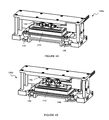
- FIGS. 4A-4B depict configurations of a linear actuator of an embodiment of a molecular diagnostic module
- FIGS. 5A-5D depict elements of an embodiment of a valve actuation subsystem of a molecular diagnostic module
- FIGS. 6A-6B depict configurations of an embodiment of a valve actuation subsystem of a molecular diagnostic module
- FIGS. 7A-7C depict elements of an embodiment of a valve actuation subsystem of a molecular diagnostic module
- FIGS. 8A and 8B depict elements of an example of a valve actuation subsystem of a molecular diagnostic module
- FIG. 9 depicts elements of an embodiment of an optical subsystem of a molecular diagnostic module
- FIGS. 10A-10B depict an embodiment of a microfluidic cartridge for processing biological samples
- FIGS. 11A-11C depict an embodiment of a fluid handling system of a system for processing and detecting nucleic acids.
- FIG. 12 depicts an embodiment of a method for processing and detecting nucleic acids.
- an embodiment of a system 100 for processing biological samples includes: a molecular diagnostic module 130 comprising a microfluidic cartridge receiving module 140 , heating and cooling subsystem 150 , a magnet 160 , a valve actuation subsystem 170 , and an optical subsystem 280 .
- Other embodiments of the system 100 can further comprise a microfluidic cartridge 210 configured to facilitate sample processing; a liquid handling system 250 configured to facilitate gas and fluid delivery to different elements of the system 100 ; a processor 290 configured to analyze data resulting from a run of the system 100 ; and a user interface 295 configured to allow a user to interact with the system 100 .
- the system 100 can additionally or alternatively include any other suitable elements, as described in U.S.
- the system 100 thus functions to receive biological samples containing nucleic acids (i.e., impure nucleic acid samples), separate nucleic acids from the biological samples, and analyze nucleic acid samples according to at least one molecular diagnostic protocol (e.g., PCR).
- the system 100 is a walkaway system by which a user loads a set of biological samples containing nucleic acids, and receives a set of data resulting from a molecular diagnostic protocol without any further sample manipulation by the user.
- the system 100 facilitates aspects of sample preparation for a molecular diagnostic protocol, with some sample manipulation performed by the user.
- a liquid handling system 250 aspirates a set of biological samples and dispenses the biological samples into a microfluidic cartridge 210 , aligned within a cartridge receiving module 140 of a molecular diagnostic module 130 , and configured to be manipulated by the molecular diagnostic module 130 .
- a heating and cooling subsystem 150 , a magnet 160 , and a valve actuation subsystem 170 of the molecular diagnostic module 130 then facilitate separation of a set of nucleic acids from the biological samples, as the liquid handling system 250 dispenses wash solutions, release solutions, and/or air at appropriate stages.
- the liquid handling system 250 then aspirates the set of nucleic acids from the microfluidic cartridge 210 contained within the molecular diagnostic module 130 , combines the set of nucleic acids with a set of molecular diagnostic reagents, and dispenses the set of nucleic acids combined with the set of molecular diagnostic reagents (i.e., set of nucleic acid-reagent mixtures) into the microfluidic cartridge 210 within the molecular diagnostic module 130 .
- the heating and cooling subsystem 150 , optical subsystem 180 and valve actuation subsystem 170 of the molecular diagnostic module 130 then facilitate analysis of the set of nucleic acid-reagent mixtures by a processor configured to display information on a user interface.
- an embodiment of the molecular diagnostic module 130 of the system 100 includes a cartridge receiving module 140 , a heating and cooling subsystem 150 , a magnet 160 , a valve actuation subsystem 170 , and an optical subsystem 280 , and functions to manipulate a microfluidic cartridge 210 for processing of a biological sample containing nucleic acids.
- the molecular diagnostic module 130 is preferably configured to operate in parallel with at least one other molecular diagnostic module 130 , such that multiple microfluidic cartridges 210 containing biological samples may be processed simultaneously.
- the molecular diagnostic module 130 is configured to be stackable with another molecular diagnostic module 130 in a manner that enables access to a microfluidic cartridge 210 within each molecular diagnostic module 130 .
- the molecular diagnostic module 130 may not be configured to stack with another molecular diagnostic module, such that the molecular diagnostic modules 130 are configured to rest side-by-side on the same plane. Elements of an embodiment of the molecular diagnostic module 130 are further described in sections 1.1.1 to 1.1.4 below.
- the cartridge receiving module 140 of the molecular diagnostic module 130 comprises a cartridge platform 141 including a cartridge loading guiderail 142 , a cartridge stop 143 , a magnet receiving slot 144 , and a set of access regions 145 ; a linear actuator 146 configured to displace a microfluidic cartridge 210 resting on the cartridge platform 141 , and a set of springs 148 coupled to the cartridge platform 141 .
- the cartridge receiving module 140 thus functions to receive, align, and compress a microfluidic cartridge 210 for processing of a biological sample according to a molecular diagnostic assay protocol.
- the cartridge platform 141 is preferably configured to receive a microfluidic cartridge 210 along a cartridge loading guiderail 142 until it reaches a cartridge stop 143 , and be vertically displaced by the linear actuator 146 , which places a biasing force against the set of springs 148 coupled to the cartridge platform 141 .
- the magnet receiving slot 144 and the set of access regions 145 provide access, by a magnet 160 and a valve actuation subsystem 170 , to the microfluidic cartridge 210 , as the microfluidic cartridge 210 is vertically displaced by the linear actuator 146 .
- the cartridge platform 141 includes a cartridge loading guiderail 142 , a cartridge stop 143 , a magnet receiving slot 144 , and a set of access regions 145 , and functions to receive and align a microfluidic cartridge 210 , while providing access to the microfluidic cartridge 210 by a magnet 160 and a valve actuation subsystem 170 .
- an embodiment of the cartridge platform 141 includes a pair of parallel cartridge loading guiderails 142 , initiating at a pair of inwardly tapering protrusions configured to guide a microfluidic cartridge toward the pair of parallel cartridge loading guiderails 142 , and spanning two short edges of the cartridge platform 141 .
- the embodiment of the cartridge platform 141 also includes a cartridge stop 143 comprising a vertical tab oriented perpendicular to the cartridge loading guiderails 142 , and spanning a long edge of the cartridge platform.
- the cartridge loading guiderails 142 and the cartridge stop 143 are configured such that a microfluidic cartridge 210 slides between the cartridge loading guiderails 142 and hits the cartridge stop 143 to signal proper alignment.
- the cartridge loading guiderails 142 and the cartridge stop 143 can be configured such that a microfluidic cartridge slides over or along the cartridge loading guiderails 142 , after which the cartridge stop 143 couples to a portion of the microfluidic cartridge 210 to ensure proper alignment of the microfluidic cartridge. Additional variations of the cartridge loading guiderails 142 and the cartridge stop 143 can be used to enable reception and alignment of a microfluidic cartridge 210 by the molecular diagnostic module 130 .
- the embodiment of the cartridge platform 141 shown in FIG. 2 also includes a set of access regions 145 , oriented perpendicular to the parallel cartridge loading guiderails 142 and configured to provide access to a valve actuation subsystem 170 , and a magnet receiving slot 144 located among the set of access regions 145 .
- the magnet receiving slot 144 and the set of access regions 145 substantially span a long dimension of the cartridge platform 141 , as shown in FIG. 2 , and are configured to correspond to locations on a microfluidic cartridge 210 requiring a magnetic field and/or valving to enable processing of a biological sample and nucleic acid detection once the microfluidic cartridge 210 has been aligned within the molecular diagnostic module 130 .
- the magnet receiving slot 144 and the set of access regions 145 can accommodate other cartridges with alternative regions requiring magnetic fields and/or valving to enable other protocols.
- the magnet receiving slot 144 and the access regions can comprise one continuous void of the cartridge platform 141 , such that the cartridge platform 141 supports a microfluidic cartridge 210 along the periphery of the microfluidic cartridge 210 , but forms a continuous void under a majority of the footprint of the microfluidic cartridge 210 .
- the linear actuator 146 functions to linearly displace a microfluidic cartridge 210 resting on the cartridge platform 141 , in order to compress the microfluidic cartridge 210 and position the microfluidic cartridge 210 between a cartridge heater 153 and an optical subsystem 280 on one side of the microfluidic cartridge 210 , and a magnet 160 and detection chamber heaters 157 on another side of the microfluidic cartridge 210 , as described in further detail below.
- the linear actuator 146 also functions to provide a sufficient counterforce to the valve actuation subsystem 170 such that a microfluidic cartridge 210 within the molecular diagnostic module 130 remains properly situation upon manipulation by the valve actuation subsystem 170 .
- the linear actuator 146 further functions to move a nozzle 149 coupled to the liquid handling system 250 , in order to couple the liquid handling system 250 to a fluid port 222 of the microfluidic cartridge 210 .
- the linear actuator 146 is preferably coupled to the cartridge heater 153 and a portion of the optical subsystem 280 , and vertically displaces the cartridge heater 153 and the optical subsystem 280 to position the cartridge heater 153 and the optical subsystem 280 over the microfluidic cartridge 210 .
- the vertical displacement also allows the microfluidic cartridge 210 to receive a magnet 160 , which provides a magnetic field to facilitate a subset of a molecular diagnostic protocol, and detection chamber heaters 157 , which allows amplification of nucleic acids for molecular diagnostic protocols requiring heating and cooling of the nucleic acid (e.g. PCR).
- the linear actuator 146 is a scissor jack actuator configured to apply substantially uniform pressure over all occlusion positions of a microfluidic cartridge 210 aligned within the molecular diagnostic module 130 , and to operate in at least two configurations. In a retracted configuration 146 a , as shown in FIG.
- the scissor jack actuator has not linearly displaced the cartridge platform 141 , and in an extended configuration 146 b , as shown in FIG. 4B , the scissor jack actuator has linearly displaced the microfluidic cartridge 210 to position the microfluidic cartridge 210 between the subsystems 153 , and 180 , and the magnet 160 and detection chamber heaters 157 .
- the extended configuration 146 b of the scissor jack actuator is configured to couple the nozzle 149 to a fluid port 222 of the microfluidic cartridge 210 , such that the liquid handling system 250 can deliver solutions and gases for processing of biological samples.
- the linear actuator 146 may alternatively be any appropriate linear actuator, such as a hydraulic, pneumatic, or motor-driven linear actuator, configured to linearly displace a microfluidic cartridge within the molecular diagnostic module 130 .
- a set of springs 148 is coupled to the cartridge platform 141 and functions to provide a counteracting force against the linear actuator 146 as the linear actuator 146 displaces a microfluidic cartridge 210 resting on the cartridge platform 141 .
- the set of springs 148 thus allows the cartridge platform 141 to return to a position that allows the microfluidic cartridge 210 to be eloaded and unloaded from the molecular diagnostic module 130 when the linear actuator 146 is in a retracted configuration 146 b , as shown in FIG. 4B .
- the nozzle 149 , the heating and cooling subsystem 150 , the cartridge heater 153 , and the magnet 160 are preferably coupled to springs, such that springs are positioned between elements 149 , 150 , 153 , and 160 , and substrates that elements 149 , 150 , 153 , and 160 are mounted to.
- an elastomeric material is preferably positioned between elements 149 , 150 , 153 , and 160 , and substrates that elements 149 , 150 , 153 , and 160 are mounted to.
- the springs and/or elastomeric material function to provide proper functioning and alignment of subsystems of the molecular diagnostic module 130 as the linear actuator 146 is extended or retracted, contributing to reliability and a reduction in stack up tolerance risk.
- the springs and/or elastomeric material further function to allow more pressure to be applied to occlusion positions of a microfluidic cartridge 210 aligned within the molecular diagnostic module 130 , and an appropriate pressure to be applied to elements 149 , 150 , 153 and 160 of the molecular diagnostic module 130 .
- proper contact is maintained between elements 149 , 150 , 153 , and 160 , and a microfluidic cartridge 210 being manipulated by the molecular diagnostic module.
- the heating and cooling subsystem 150 of the molecular diagnostic module 130 comprises a cartridge heater 153 , a fan 155 , and a set of detection chamber heaters 157 and functions to controllably heat portions of a microfluidic cartridge 210 for processing of a biological sample containing nucleic acids according to a molecular diagnostic protocol.
- a cartridge heater 153 a fan 155 , and a set of detection chamber heaters 157 and functions to controllably heat portions of a microfluidic cartridge 210 for processing of a biological sample containing nucleic acids according to a molecular diagnostic protocol.
- the cartridge heater 153 is preferably coupled to the linear actuator 146 of the cartridge receiving module 140 and configured to span a central region of a microfluidic cartridge 210 aligned within the molecular diagnostic module 130 , the fan 155 is located at a back wall of the cartridge receiving module 140 , and the set of detection chamber heaters 157 is located inferior to a set of detection chambers of the microfluidic cartridge 210 .
- the heating and cooling subsystem 150 can have any appropriate alternative configuration that provides controlled heating and cooling to a microfluidic cartridge within the molecular diagnostic module 130 .
- the cartridge heater 153 , the fan 155 , and the set of detection chamber heaters 157 are preferably those described in U.S. application Ser. No. 13/766,359 entitled “System and Method for Processing and Detecting Nucleic Acids” and filed on 13 Feb. 2013, which is incorporated herein in its entirety by this reference; however, in other variations, the cartridge heater 153 , the fan 155 , and/or the set of detection chamber heaters 157 can be any other suitable cartridge heater 153 , fan 155 , and/or set of detection chamber heaters 157 .
- the magnet 160 of the molecular diagnostic module 130 functions to provide a magnetic field for isolation and extraction of nucleic acids bound to magnetic beads within a microfluidic cartridge 210 , aligned within the molecular diagnostic module 130 .
- the magnet 160 is fixed within the molecular diagnostic module 130 , such that the extended configuration 146 b of the linear actuator 146 allows the magnet 160 to pass through the magnet receiving slot 144 of the cartridge receiving module 140 and into a magnet housing region 218 of the microfluidic cartridge 210 .
- the magnet 160 is a rectangular prism-shaped magnet 160 fixed under the cartridge platform 141 , and configured to pass through the cartridge platform 141 , into a magnet housing region 218 located under the heating region of the microfluidic cartridge 210 .
- the magnet 160 is one of two or three magnets lined up in parallel, such that each of the fluidic pathways of a microfluidic cartridge housing the magnets is exposed to two or three times as much magnetic flux, and two to threes times as many opportunities to capture magnetic beads.
- the magnet 160 is a single magnet configured to expose a set of fluidic pathways to a magnetic field.
- the magnet 160 or group of multiple magnets is coupled to a magnet holder within the molecular diagnostic module 130 .
- the magnet holder is preferably composed of an insulating material, such that the magnet holder does not interfere with proper functioning of the cartridge heater 153 .
- the magnet holder may not be composed of an insulating material.
- the magnet 160 is preferably a magnet 160 as described in U.S. application Ser. No. 13/766,359 entitled “System and Method for Processing and Detecting Nucleic Acids” and filed on 13 Feb. 2013; however, in other variations, the magnet 160 can be any other suitable magnet. Alternative configurations and/or compositions of the magnet 160 may also be appropriate in facilitating isolation and extraction of nucleic acids bound to magnetic beads within the microfluidic cartridge 210 .
- the valve actuation subsystem 170 includes an actuation substrate 171 including an array of active regions 172 ; a set of pins 174 , each pin 175 in the set of pins 174 including a base end 176 , a distal end 177 , and a displacement region 178 ; a pin housing 180 including a set of cavities 181 that surround and guide displacement of each pin 175 in the set of pins 174 ; a spring plate 183 including a set of springs 184 coupled to the set of pins 174 ; and an actuator 187 coupled to at least one of the actuation substrate 171 , the pin housing 180 , and the spring plate 183 , and configured to provide relative displacement between the array of active regions 172 and the set of pins 174 .
- the valve actuation subsystem 170 functions to manipulate a set of occlusion positions of a microfluidic cartridge 210 , as described in further detail below, wherein the set of occlusion positions affect sample and/or fluid (e.g., air, reagent, etc.) transfer through fluidic pathways of the microfluidic cartridge 210 .
- sample and/or fluid e.g., air, reagent, etc.
- the valve actuation subsystem 170 enables portions of the fluidic pathway(s) to be reversibly opened and closed, or maintained in a closed position, by actuation of the set of pins 174 .
- the valve actuation subsystem 170 is preferably situated at a location inferior to that of the cartridge platform 141 , as shown in FIG.
- valve actuation subsystem 170 can be situated at a location superior to that of the cartridge platform 141 , such that the set of pins occlude occlusion positions of the microfluidic cartridge 210 in a superior to inferior direction.
- the valve actuation subsystem 170 can be situated relative to the cartridge platform 141 in any other suitable manner.
- the actuation substrate 171 includes an array of active regions 172 , which function to interact with one or more displacement regions 178 of the set of pins 174 , in order to transition pins 175 of the set of pins 174 into extended configurations 175 a and/or retracted configurations 175 b , as shown in FIGS. 6A and 6B .
- the array of active regions 172 is preferably configured such that subsets of the set of pins 174 can be placed into specific and repeatable configurations (e.g., an array of extended and retracted configurations), in order to manipulate fluidic pathways of the microfluidic cartridge 210 in a repeatable manner for processing nucleic acids.
- the actuation substrate 171 transforms lateral motion of the actuation substrate 171 into vertical actuation of one or more pins of the set of pins 174 , in the orientation shown in FIGS. 5A and 5C ; however, in other variations, the valve actuation subsystem 171 can be configured to transform any other suitable motion (e.g., rotational motion, non-lateral motion, etc.) of the actuation substrate 171 into actuation of one or more pins of the set of pins 174 .
- suitable motion e.g., rotational motion, non-lateral motion, etc.
- the array of active regions 172 preferably includes elements that physically contact the set of pins 174 during motion of the actuation substrate 171 , thereby directly moving one or more pins 175 of the set of pins 174 into a desired configuration.
- the array of active regions 172 includes at least one protrusion (e.g., peak) and can additionally or alternatively include at least one recessed area (e.g., valley) that physically enable raising and/or lowering of the pin(s) of the set of pins 174 .
- the array of active regions 172 can include elements that transmit forces to the pin(s) of the set of pins 174 , thereby moving the pin(s) into a desired configuration without physical contact.
- the array of active regions 172 includes an array of magnetic elements that produce magnetic fields that enable raising and/or lowering of the pin(s) of the set of pins 174 .
- elements of the array of active regions 172 can be situated at a first surface 179 of the actuation substrate 171 , such that motion of the actuation substrate 171 is transformed into actuation of pins contacting the first surface 179 of the actuation substrate.
- the first surface 179 can be an inferior surface of the actuation substrate 171 , in the orientation shown in FIGS. 5A and 5C , or a superior surface of the actuation substrate 171 .
- the elements of the array of active regions 172 can be situated at multiple surfaces of the actuation substrate 171 , and can additionally or alternatively be embedded within the actuation substrate 171 (e.g., as in an embedded array of magnetic elements).
- the actuation substrate 171 can include combinations of elements that physically contact the set of pins 174 and elements that transmit forces to the set of pins 174 without physical contact.
- the actuation substrate 171 comprises a cam card 173 including a set of peaks 185 and valleys 186 , and functions to transform linear motion in one plane to vertical motion in another plane.
- the cam card 173 contacts the displacement regions 178 of pins in a set of pins 172 , such that when a peak 185 of the cam card 173 enters alignment with a displacement region 178 , the pin is in one configuration, and when a valley 186 of the cam card 173 enters alignment with a displacement region, the pin is in a another configuration.
- Every peak in the set of peaks 185 and valleys 186 is preferably identical in morphology and dimension; however, in variations, the set of peaks 185 and valleys 186 can include one or more peaks having different dimensions and/or morphologies from other peaks in the set of peaks 185 and valleys 186 .
- every valley in the set of peaks 185 and valleys 186 is preferably identical in morphology and dimension; however, in variations, the set of peaks 185 and valleys 186 can include one or more valleys having different dimensions and/or morphologies from other valleys in the set of peaks 185 and valleys 186 .
- the set of peaks 185 and valleys 186 can be configured to provide an identical range of motion for every pin 175 in the set of pins 174 , or can be configured to provide different ranges of motion for pins of the set of pins 175 .
- peaks and/or valleys of the set of peaks 185 and valleys 186 can be adjustable in dimension in order to provide adjustable ranges of motion or to compensate for wear of peaks and/or valleys.
- the peaks 185 and valleys 186 of the cam card 173 are preferably in a set configuration, as shown in FIG. 5C , such that lateral motion of the cam card 173 to a set position places the set of pins 174 in a specific configuration in a reversible and/or repeatable manner.
- the set configuration further functions to enable manipulation of normally closed and normally open occlusion positions, in a specific configuration, of a microfluidic cartridge 210 interacting with the valve actuation subsystem 170 .
- lateral movement of the cam card 173 to different positions of a set of positions consistently places subsets of the set of pins 172 into desired configurations to occlude different portions of a fluidic pathway of a microfluidic cartridge 210 in contact with the set of pins 174 .
- desired portions of a fluidic pathway of the microfluidic cartridge 210 can be selectively occluded and opened to facilitate processing of a biological sample according to any appropriate tissue, cellular, or molecular diagnostic assay protocol.
- the set of peaks 185 and valleys 186 of the cam card 173 are situated at a first face 179 of the cam card 173 , such that lateral motion of the cam card 173 is transformed into actuation of pins contacting the first face 179 of the cam card 173 .
- the first face 179 is oriented away from distal ends 177 of the set of pins 174 , as described in further detail below, such that peaks 185 of the cam card 173 are configured to retract pins of the set of pins 174 , and valleys of the cam card 173 are configured to enable extension of pins of the set of pins.
- the set of peaks 185 and valleys 186 can be situated at multiple faces of the cam card 173 .
- the cam card 173 is configured to be laterally displaced in one coordinate direction within a plane (e.g., by a linear actuator); however in another variation, the cam card 173 is configured to be laterally displaced in only multiple directions within a plane (e.g., by multiple linear actuators, by an x-y linear actuator).
- the peaks 185 of the cam card 173 are raised 1 mm above the valleys 186 of the cam card 173 .
- the peaks 185 are identical and have a substantially semicircular cross section with a radius of 1 millimeter, while the valleys 186 are substantially planar and situated in line with the base of each peak 185 .
- Alternative variations can, however, include any appropriate configurations and geometries of a cam card 173 with peaks 185 and valleys 186 , driven by any appropriate actuator.
- the actuation substrate 171 can be a cam wheel comprising an array of active regions 172 configured to enable actuation of pins contacting a cylindrical surface, and configured to convert rotary motion to linear (i.e., vertical) motion of the set of pins 174 .
- the cam wheel can be configured to contact base ends 176 of pins in the set of pins 174 , and can be coupled to a motor shaft and driven by a motor.
- the actuation substrate 171 can altogether be replaced by a set of cams, each configured to individually rotate about an axis.
- rotating subsets of the set of cams raises/lowers corresponding subsets of the set of pins 174 , and occludes specific portions of a of a microfluidic cartridge 210 in contact with the set of pins 174 .
- the set of pins 174 is configured to interact with the actuation substrate 171 , and functions to enable selective occlusion and/or opening of fluidic pathways of the microfluidic cartridge 210 , by way of the set of occlusion positions.
- the pins of the set of pins 174 preferably include cylindrical portions and, in the orientation shown in FIGS. 5A and 5C , each pin in the set of pins 174 preferably has a portion defining a circular cross section configured to facilitate sliding within a pin housing 180 .
- each pin can comprise any appropriate cross-sectional geometry (e.g., rectangular) and/or end shape (e.g., flat or pointed) to facilitate occlusion of a fluidic pathway of a microfluidic cartridge 210 .
- each pin in the set of pins 174 is composed of a low-friction material to facilitate sliding motions (i.e., in cooperation with an actuation substrate 171 or within a pin housing 180 ); however, each pin may alternatively be coated with a lubricant configured to facilitate sliding motions.
- the valve actuation subsystem 170 comprises 12 sets of pins 174 configured to selectively occlude 12 fluidic pathways of a microfluidic cartridge 210 aligned within the molecular diagnostic module 130 ; however, other embodiments can comprise any other suitable number of sets of pins 174 .
- Each pin 175 in the set of pins 174 preferably includes a base end 176 , a distal end 177 , and a displacement region 178 .
- one or more pins 175 of the set of pins 174 can additionally include a stop region 188 configured to interface with the pin housing 180 in a manner that defines a range of motion for the pin(s) including a stop region 188 .
- the base end 176 of a pin 175 functions to interact with springs of a spring plate 183 , wherein the springs 184 provide a biasing force against pins of the set of pins 174 , as described in further detail below.
- the base end 176 can be configured to abut a spring of the spring plate 183 , and can additionally or alternatively be coupled to the spring of the spring plate 183 in any other suitable manner.
- the distal end 177 of a pin 175 functions to interact with an occlusion position of a fluidic pathway of a microfluidic cartridge 210 aligned with the valve actuation subsystem 170 of an embodiment of the molecular diagnostic module 130 .
- the base end 176 and/or the distal end 177 of a pin 175 can be cylindrical in morphology, in order to provide an occlusion surface that is substantially circular, ovaloid, or ellipsoidal.
- the base end 176 and/or the distal end 177 of pin 175 can be polygonal prismatic (e.g., square prismatic, triangular prismatic) in order to provide an occlusion surface that is polygonal, or amorphous prismatic in morphology.
- any suitable portion of a pin 175 can be configured to interact with a spring in order to provide a biasing force against the pin 175 .
- the displacement region 178 of a pin 175 functions to interact with one or more active regions of the array of active regions to enable actuation of the pin 175 .
- the displacement region 178 is substantially aligned with the actuation substrate 171 , in order to facilitate interaction between an active region 172 of the actuation substrate 171 and a displacement region 178 of a pin 175 .
- the displacement region 178 preferably mechanistically complements one or more active regions 172 of actuation substrate 171 .
- the displacement region can include a portion that physically contact an active region 172 during motion of the actuation substrate 171 , and in one such variation, the displacement region 178 includes at least one protrusion (e.g., peak) or recessed area (e.g., valley) that physically interacts with the active region to raise or lower the pin 175 .
- the displacement region 178 can include additionally or alternatively include a portion that responds to forces provided by the active region(s) 172 of the actuation substrate 171 , thereby moving the pin into a desired configuration without physical contact between the pin 175 and an active region.
- the displacement region can include a magnetic element that responds to magnetic fields produced by active regions of the actuation substrate 171 to raise or lowering the pin.
- the magnetic element of the displacement region 178 can be configured to be drawn toward the magnetic element of an active region 172 , or can be configured to be repelled away from the magnetic element of the active region 172 .
- the displacement region 178 of a pin 175 is preferably incorporated within the body of the pin 175 , between the base end 176 and the distal end 177 of the pin 175 .
- the displacement region 178 can be incorporated within an opening 189 defined within the body of the pin 175 .
- the displacement region 178 of a pin 175 can additionally or alternatively be biased toward an exterior surface of the pin 175 , defined at least in part at a recessed region of the exterior surface of the pin 175 , or coupled to the pin in any other suitable manner (e.g., using an extension configured to transmit motion from the displacement region to the pin).
- the displacement region 178 includes a semi-cylindrical protrusion defined within a slotted opening 189 , wherein the base of the semi-cylindrical protrusion is situated at the base end of the slotted opening (i.e., toward the base end 176 of the pin 175 ).
- the actuation substrate 171 thus comprises at least one arm 199 including an active region 172 (e.g., a peak, a valley), as shown in FIG.
- a magnetic element proximal a surface of the slotted opening of the displacement region 178 of the pin 175 can be configured to interact with a corresponding magnetic element (i.e., an active region 172 ) of an arm 199 of the actuation substrate 171 .
- the magnetic element of the arm 199 can be configured to magnetically repel or draw the magnetic element of the displacement region 178 of the pin 175 , in order to provide actuation of the pin.
- the displacement region 178 of a pin can be configured to complement configurations of active regions 172 of the actuation substrate 171 in any other suitable manner.
- the stop region 188 is preferably a protruding portion of a pin 175 that interacts with a complementary portion of the pin housing 180 , such that the complementary portion of the pin housing obstructs further motion of the pin 175 .
- the stop region 188 can comprise a region of the pin 175 that has a larger width or diameter than other regions of the pin 175 , and can additionally or alternatively include a protrusion that limits range of motion of the pin in any other suitable manner.
- a pin 175 includes a stop region 188 located between the base end 176 and the distal end 177 of a pin 175 and defined by a larger diameter than that of the pin housing 180 .
- each pin 175 of the set of pins 174 can include multiple stop regions 188 configured to define ranges of motion for the set of pins.
- Each pin 175 in the set of pins 174 preferably operates in an extended configuration 175 a and/or a retracted configuration 175 b .
- each pin 175 of the set of pins 174 is configured to reversibly and repeatably transition between the extended configuration 175 a and the retracted configuration 175 b .
- one or more pins 175 of the set of pins 174 can be configured to achieve only one of the extended configuration 175 a and the retracted configuration 175 b , and/or a pin 175 of the set of pins 174 can be configured to be locked semi-permanently in a configuration 175 a , 175 b upon entering the configuration 188 , 189 .
- the distal end 177 of the pin 175 is configured to protrude from an opening of the pin housing 180 , in order to provide an occluding force at a fluidic pathway of a microfluidic cartridge 210 interacting with the valve actuation subsystem 170 .
- the distal end 177 of the pin 175 is configured to retract from the opening of the pin housing 180 , in order to remove an occluding force at a fluidic pathway of a microfluidic cartridge 210 interacting with the valve actuation subsystem 170 .
- the extended configuration is activated by translation of the active region (e.g., a peak, a magnet) away from the displacement region
- the retracted configuration is activated by translation of an active region (e.g., a peak, a magnet) of the actuation substrate into alignment with the displacement region.
- the extended configuration 175 a is activated as a peak of the actuation substrate 171 is moved away from the protrusion of the displacement region 178 of a pin 175
- the retracted configuration 175 b is activated as a peak of the actuation substrate 171 is moved into alignment with the protrusion of the displacement region 178 (i.e., the peak of the actuation substrate 171 pushes the pin 175 downward by way of the protrusion in the displacement region 178 ).
- the extended and retracted configurations 175 a , 175 b can, however, be activated in any other suitable manner.
- the pin housing 180 includes a set of cavities 181 , which function to surround and guide displacement of each pin 175 in the set of pins 174 .
- the pin housing 180 functions to constrain and guide motion of each pin 175 in the set of pins 174 , as the actuation substrate 171 moves and interacts with the set of pins 174 .
- each pin 175 in the set of pins 174 is surrounded by an individual cavity of the set of cavities 181 ; however, in another variation a cavity of the set of cavities 181 can be configured to surround multiple pins in the set of pins 174 . In an example shown in FIGS.
- the pin housing 180 is located under the cartridge platform 141 , such that the set of cavities 181 is aligned with the set of access regions 145 , to provide access, by the set of pins 174 , to a microfluidic cartridge 210 aligned on the cartridge platform 141 .
- the pin housing 180 thus constrains the set of pins 174 , such that each pin can only move linearly in a vertical direction, and with a set range of motion.
- Each cavity of the set of cavities 181 preferably has a constricted region (i.e., serving as a pin stop) configured to limit the motion of a pin within a cavity (i.e., by way of the stop region 188 of the pin); however, each cavity of the set of cavities 181 may alternatively not include a constricted region.
- surfaces of the pin housing 180 contacting the set of pins 174 are composed of a low friction material to facilitate sliding of a pin 175 within a cavity of the pin housing 180 ; however, surfaces of the pin housing 180 contacting the set of pins 174 may alternatively be coated with a lubricant configured to facilitate sliding motions.
- Other variations of the pin housing 180 and the set of pins 174 may include no additional provisions to facilitate sliding of a pin 175 within a cavity of the set of cavities 181 .
- the spring plate 183 includes a set of springs 184 coupled to the set of pins 174 , and functions to provide biasing forces against the set of pins, in order to bias each pin in the set of pins in a specific direction.
- the spring plate 183 is preferably situated proximal the base ends 176 of the set of pins 174 ; however, the spring plate 183 can alternatively be configured relative to other elements of the valve actuation subsystem 170 in any other suitable manner.
- a spring of the set of springs 184 preferably functions to provide a counteracting force to restore a pin to a desired configuration (e.g., an extended configuration 175 a , a retracted configuration 175 b ).
- a spring of the set of springs 184 can additionally function to allow sufficient force to be transmitted through the pin 175 to fully occlude a microfluidic channel of a microfluidic cartridge 210 , while preventing forces from being generated that could damage the pin 175 , the microfluidic cartridge 210 , and/or the actuation substrate 171 .
- a spring of the set of springs 184 is configured to abut the base end 176 of a pin 175 , and/or a region substantially proximal the base end 176 of the pin 175 in order to transmit a biasing force to the pin 175 .
- a spring of the set of springs 184 can additionally or alternatively be configured to couple to any other suitable portion of a pin 175 .
- the set of springs 184 can be configured to bias every pin of the set of pins 174 in the same direction with identical magnitudes of force; however, in other variations, the set of springs 185 can be configured to bias different pins of the set of pins 175 in different directions, and/or with different magnitudes of force.
- the set of springs 184 is configured to bias every pin 175 of the set of pins 174 toward an extended configuration 175 a , such that when an active region (e.g., a peak, a magnet) of the actuation substrate 171 substantially enters alignment with a displacement region 178 of a pin 175 , the pin 175 is transitioned into a retracted configuration 175 b and the spring contacting the pin is compressed (e.g., further compressed, transitioned from a neutral state to a state of compression). Then, in the first variation, when the active region of the actuation substrate 171 is moved out of alignment with the displacement region 178 , the pin 175 is restored to an extended state.
- an active region e.g., a peak, a magnet
- the spring(s) of the set of springs 184 can be configured to bias the pin(s) of the set of pins 174 toward a retracted configuration 175 b , such that alignment of the active region(s) of the actuation substrate 171 with the displacement region(s) 178 of the pin(s) transitions the pin(s) into an extended configuration 175 a .
- the springs can be configured to bias the pins in any other suitable manner.
- the actuator 187 is coupled to at least one of the actuation substrate 171 , the pin housing 180 , and the spring plate 183 , and functions to provide relative displacement between the array of active regions 172 and the set of pins 174 , thus transforming motion of the actuation substrate 171 into motion of subsets of the set of pins 174 .
- the actuator 187 is preferably a linear actuator; however, the actuator 187 can additionally or alternatively comprise any other suitable actuator.
- the actuator 187 is coupled to the actuation substrate 171 with the set of pins 174 , the spring housing 180 , and the spring plate 183 substantially stationary, such that actuation of the actuator 187 manipulates motion of the set of pins 174 in order to occlude pathways of the microfluidic cartridge 210 .
- the actuator can be coupled to one end of the actuation substrate 171 (e.g., using a set of coupling points defined within the actuation substrate 171 ); however, in other variations, the actuator 187 can be coupled to any other suitable portion of the actuation substrate 171 .
- the actuator 187 can be configured to move the set of pins 174 , within the pin housing 180 , relative to the actuation substrate 171 , in order to occlude pathways of the microfluidic cartridge 210 .
- the actuator 187 can be coupled to any other suitable portion of the valve actuation subsystem 170 .
- the set of pins 174 and the pin housing 180 are located directly under the microfluidic cartridge 210 , after the microfluidic cartridge 210 has been aligned within the molecular diagnostic module 130 , such that the set of pins can access the microfluidic cartridge 210 through the access regions 145 of the cartridge platform 141 .
- the actuation substrate 171 in the specific example is situated amongst the set of pins 174 , between base ends and distal ends of the set of pins 174 , and comprises a set of arms including the active regions 172 (i.e., peaks and valleys) defined at a bottom face of the arms 199 of the actuation substrate, in the orientation shown in FIG. 5C .
- peaks 185 of the actuation substrate 171 are configured to push pins downward to a retracted configuration 189 by way of semi-cylindrical protrusions defined within slotted openings 189 of the pins 175
- valleys 186 of the actuation substrate 171 are configured to restore pins 175 of an extended configuration 188 .
- the actuation substrate 171 includes four parallel arms 199 configured to manipulate eight occlusion positions of a microfluidic cartridge 210 , with each arm 199 configured to pass through slotted openings in two pins 175 , in order to manipulate two occlusion positions of the microfluidic cartridge 210 .
- the four parallel arms 199 include a first arm including two peaks and two valleys, in alternation, configured to manipulate two normally open occlusion positions, a second arm including two valleys, configured to manipulate two normally closed occlusion positions, a third arm including two peaks and two valleys, in alternation, configured to manipulate two normally open occlusion positions, and a fourth arm including a peak and two valleys, configured to manipulate one normally open occlusion position and one normally closed occlusion position.
- Normally open and normally closed occlusion positions are further described in U.S. application Ser. No. 13/765,996 filed on 13 Feb.
- each arm has a width of ⁇ 1.22 millimeters, and is spaced apart from other arms by a gap of ⁇ 1 millimeter.
- the actuation substrate 171 in the specific example further has a maximum width of ⁇ 8.74 millimeters and a length of 13.74 centimeters, with peaks having heights 1 millimeter and valleys having depths of 1 millimeter.
- the actuation substrate 171 is coupled to an actuator 187 at an end opposite the arms 199 of the actuation substrate 171 , by way of three coupling points, as shown in FIG. 5D .
- the actuator 187 is configured to laterally displace the actuation substrate 171 to vertically displace one or more pins 175 of the set of pins 174 .
- the actuation substrate in the specific example travels on a low friction surface configured to facilitate lateral displacement of the actuation substrate 171 ; however, in other variations, the actuation substrate 171 can additionally or alternatively be configured to travel through any other suitable environment having low friction (e.g., air, lubricated surface, surface of ball bearings, etc.) in order to facilitate actuation of the actuation substrate 171 .
- low friction e.g., air, lubricated surface, surface of ball bearings, etc.
- valve actuation subsystem 170 While the system 100 preferably includes an embodiment, variation, or specific example of the valve actuation subsystem 170 described above, the system can alternatively or additionally include any other suitable valve actuation subsystem 170 , such as a valve actuation subsystem described in U.S. application Ser. No. 13/766,359 entitled “System and Method for Processing and Detecting Nucleic Acids” and filed on 13 Feb. 2013.
- the optical subsystem 280 of the molecular diagnostic module 130 comprises a set of light emitting elements 281 , a set of excitation filters 282 configured to transmit light from the set of light emitting elements 281 , a set of dichroic mirrors 283 configured to reflect light from the set of excitation filters 282 toward a set of apertures 285 configured to transmit light toward a set of nucleic acid samples, a set of emission filters 286 configured to receive and transmit light emitted by the set of nucleic acid samples, and a set of photodetectors 287 configured to facilitate analysis of light received through the set of emission filters 286 .
- the optical subsystem 280 can further comprise a set of lenses 284 configured to focus light onto the set of nucleic acid samples.
- the optical subsystem 280 thus functions to transmit light at excitation wavelengths toward a set of nucleic acid samples and to receive light at emission wavelengths from a set of nucleic acid samples.
- the optical subsystem 280 is coupled to an optical subsystem actuator 288 configured to laterally displace and align the optical subsystem 280 relative to the set of nucleic acid samples, and is further coupled to a linear actuator 146 of the cartridge receiving module 140 to position the optical subsystem 280 closer to the set of nucleic acid samples.
- the optical subsystem 280 may not be coupled to a linear actuator 146 of the cartridge receiving module 140 , and may only be configured to translate laterally in one direction.
- the optical subsystem 280 is located within the molecular diagnostic module 130 and coupled to the linear actuator 146 of the cartridge receiving module 140 , such that, in the extended configuration 146 b of the linear actuator 146 , the optical subsystem 280 can be positioned closer to a microfluidic cartridge 210 aligned within the molecular diagnostic module.
- the optical subsystem 280 is positioned away from the microfluidic cartridge 210 in the retracted configuration 146 a of the linear actuator 146 .
- the optical subsystem 280 is further coupled to an optical subsystem actuator 288 configured to laterally displace the optical subsystem 280 relative to the microfluidic cartridge 210 , such that the optical subsystem 280 can be aligned with a set of detection chambers of the microfluidic cartridge 210 .
- the optical subsystem 280 is preferably an optical subsystem 280 as described in U.S. application Ser. No. 13/766,359 entitled “System and Method for Processing and Detecting Nucleic Acids” and filed on 13 Feb. 2013; however, in other variations, the optical subsystem 180 can additionally or alternatively include any other suitable optical subsystem elements configured to transmit excitation wavelengths of light to samples, and/or receive emission wavelengths of light from the samples.
- the microfluidic cartridge 210 functions to receive a set of magnetic bead-samples, facilitate separation of nucleic acids from the set of magnetic bead-samples, receive a set of nucleic acid-reagent samples, and facilitate analysis of nucleic acids from the set of nucleic acid-reagent samples. In one embodiment, as shown in FIGS.
- the microfluidic cartridge 210 comprises a top layer 211 including a set of sample port-reagent port pairs 212 and a set of detection chambers 213 ; an intermediate substrate 214 , coupled to the top layer 211 and partially separated from the top layer 211 by a film layer 215 , configured to form a waste chamber 216 ; an elastomeric layer 217 partially situated on the intermediate substrate 214 ; a magnet housing region 218 accessible by a magnet 160 providing a magnetic field; and a set of fluidic pathways 219 , each formed by at least a portion of the top layer 211 , a portion of the film layer 215 , and a portion of the elastomeric layer 217 .
- the microfluidic cartridge 10 further comprises a bottom layer 221 coupled to the intermediate substrate 214 and configured to seal the waste chamber 216 .
- the top layer 211 of the microfluidic cartridge 210 further comprises a shared fluid port 222 , a vent region 223 , and a heating region 224 , such that each fluidic pathway 220 in the set of fluidic pathways 219 is fluidically coupled to a sample port-reagent port pair 229 , the shared fluid port 222 , the waste chamber 216 , and a detection chamber 225 , comprises a turnabout portion configured to pass through the heating region 224 and the magnetic field, and is configured to pass through the vent region 223 upstream of the detection chamber 225 .
- Each fluidic pathway 220 thus functions to receive and facilitate processing of a sample fluid containing nucleic acids as it passes through different portions of the fluidic pathway 220 .
- the microfluidic cartridge 210 is preferably configured to be received and manipulated by the molecular diagnostic module 130 , such that the cartridge receiving module 140 of the molecular diagnostic module 130 receives and aligns the microfluidic cartridge 210 within the molecular diagnostic module 130 , the heating and cooling subsystem 150 of the molecular diagnostic module 130 is configured to transfer heat to the heating region 224 of the microfluidic cartridge 210 , and the magnet 160 of the molecular diagnostic module 130 is configured to be received by the magnet housing region 218 of the microfluidic cartridge 210 to provide a magnetic field for separation of nucleic acids.
- the shared fluid port 222 of the microfluidic cartridge 210 is configured to couple to a nozzle 149 coupled to the linear actuator 146 of the cartridge receiving module 140 , such that the liquid handling system 250 can deliver fluids and gases through the shared fluid port 222 .
- the elastomeric layer 217 of the microfluidic cartridge 210 is also preferably configured to be occluded at a set of occlusion positions 226 by the valve actuation subsystem 170 of the molecular diagnostic module, in order to occlude portions of a fluidic pathway 220 of the microfluidic cartridge 210 for processing of a set of biological samples.
- the optical subsystem 180 of the molecular diagnostic module 130 is further configured to align with the set of detection chambers 213 of the microfluidic cartridge 210 , to facilitate analysis of a set of nucleic acid samples.
- the microfluidic cartridge 210 is preferably the microfluidic cartridge 210 described in U.S. application Ser. No. 13/765,996 and filed on 13 Feb. 2013, which is incorporated in its entirety by this reference, but can alternatively be any appropriate cartridge or substrate configured to receive and process a set of samples containing nucleic acids.
- the liquid handling system 250 of the system 100 includes a liquid handling arm 255 and a syringe pump 265 , as shown in FIGS. 10A-10C and functions to deliver biological samples, reagents, and gases to elements of the system 100 .
- an embodiment of the liquid handling system 250 is configured to aspirate a set of biological samples containing nucleic acids (i.e., impure nucleic acid samples), and dispense the set of biological samples into microfluidic cartridge 210 located in a molecular diagnostic module 130 .
- the embodiment of the liquid handling system 100 is further configured to facilitate separation of a set of nucleic acids from the magnetic bead-samples, by dispensing a wash solution, a release solution, and/or air into the molecular diagnostic module 130 , by the nozzle 149 coupled to the linear actuator 146 , at appropriate stages, aspirate the set of nucleic acids from the molecular diagnostic module 130 , combine the set of nucleic acids with a set of molecular diagnostic reagents, and dispense the set of nucleic acids combined with the set of molecular diagnostic reagents (i.e., set of nucleic acid-reagent mixtures) into the molecular diagnostic module 130 for further processing and analysis.
- Other embodiments of the liquid handling system 250 can be configured to perform alternative molecular diagnostic assay protocols and/or dispense and aspirate alternative fluids into and from other elements supporting a molecular diagnostic protocol.
- the liquid handling system 250 is preferably an embodiment of the liquid handling system described in U.S. application Ser. No. 13/766,359 entitled “System and Method for Processing and Detecting Nucleic Acids” and filed on 13 Feb. 2013; however, the liquid handling system 250 can additionally or alternatively include any other suitable elements configured to facilitate delivery of biological samples, reagents, and gases to elements of the system 100 .
- the system 100 can further comprise a controller coupled to at least one of the molecular diagnostic module 130 and the liquid handling system 250 , and functions to facilitate automation of the system 100 .
- the controller preferably functions to automate reception of a microfluidic cartridge, heating of biological samples within the molecular diagnostic module 130 and the detection chambers 213 , occlusion of fluidic pathways 220 by the valve actuation subsystem 170 , and analysis of a set of nucleic acid-reagent mixtures by the optical subsystem 280 .
- the controller preferably functions to automate aspiration, transfer, and delivery of fluids and/or gases to different elements of the system 100 .
- Other variations of a controller can function to automate handling, transfer, and/or storage of other elements of the system 100 , using a robotic arm or gantry or any other suitable element.
- Alternative combinations of the above variations can involve a single controller, or multiple controllers configured to perform all or a subset of the functions described above.
- the system 100 can also further comprise a processor 290 , which functions to receive and process data received from the optical subsystem 280 of the molecular diagnostic module 130 .
- the processor 290 is coupled to a user interface 295 , which functions to display processed and/or unprocessed data produced by the system 100 , settings of the system 100 , information obtained from a tag reader, or any other appropriate information.
- the processor 290 is not coupled to a user interface 295 , but comprises a connection configured to facilitate transfer of processed and/or unprocessed data produced by the system 100 , settings of the system 100 , or any other appropriate information to a device external to the system 100 .
- the system 100 can further comprise any other suitable element(s) as described in U.S. application Ser. No. 13/766,359 entitled “System and Method for Processing and Detecting Nucleic Acids” and filed on 13 Feb. 2013, or any other suitable element to facilitate reception or processing of biological samples.
- any other suitable element to facilitate reception or processing of biological samples.
- an embodiment of a method 400 for processing and detecting nucleic acids from a set of biological samples comprises: producing a set of magnetic bead-sample mixtures from the set of biological samples S 410 , heating the set of magnetic bead-sample mixtures to produce a set of nucleic acid-magnetic bead samples S 420 ; transferring each nucleic acid-magnetic bead sample of the set of nucleic acid-magnetic bead samples to a corresponding fluidic pathway of a set of fluidic pathways S 430 ; producing a set of nucleic acid volumes from the set of nucleic acid-magnetic bead samples S 440 ; combining each nucleic acid volume of the set of nucleic acid volumes with a molecular diagnostic reagent of a set of molecular diagnostic reagents to produce a set of nucleic acid-reagent mixtures S 450 ; transferring each of the set of nucleic acid-reagent mixtures
- the method 400 can further include generating a set of data based on light received form the set of nucleic acid-reagent mixtures S 480 .
- the method 400 functions to isolate and extract a set of nucleic acid volumes from a biological sample, and to facilitate analysis of the nucleic acid volumes according to at least one molecular diagnostic protocol.
- the method 400 is preferably implemented at least in part at an embodiment of the system 100 described in Section 1 above; however, the method 400 can additionally or alternatively be implemented at any other suitable system configured to process and detect nucleic acids from a set of biological samples.
- the method 400 is implemented, at least in part, as described in U.S. application Ser. No. 13/766,377 entitled “System and Method for Processing and Detecting Nucleic Acids” and filed on 13 Feb. 2013, and U.S. application Ser. No. 14/060,214 entitled “Method and Materials for Isolation of Nucleic Acid Materials” and filed on 22 Oct. 2013, which are both incorporated herein in their entirety by this reference; however, the method 400 can additionally or alternatively be implemented in any other suitable manner.
- Embodiments of the method 400 and variations thereof can be embodied and/or implemented at least in part by a machine configured to receive a computer-readable medium storing computer-readable instructions.
- the instructions are preferably executed by computer-executable components preferably integrated with the system 100 and one or more portions of the processor 273 and/or the controller 272 .
- the computer-readable medium can be stored on any suitable computer-readable media such as RAMs, ROMs, flash memory, EEPROMs, optical devices (CD or DVD), hard drives, floppy drives, or any suitable device.
- the computer-executable component is preferably a general or application specific processor, but any suitable dedicated hardware or hardware/firmware combination device can alternatively or additionally execute the instructions.
- each block in the flowchart or block diagrams may represent a module, segment, or portion of code, which comprises one or more executable instructions for implementing the specified logical function(s).
- the functions noted in the block can occur out of the order noted in the FIGURES. For example, two blocks shown in succession may, in fact, be executed substantially concurrently, or the blocks may sometimes be executed in the reverse order, depending upon the functionality involved.
Abstract
Description
Claims (20)
Priority Applications (7)
| Application Number | Priority Date | Filing Date | Title |
|---|---|---|---|
| US14/229,396 US9637775B2 (en) | 2012-02-13 | 2014-03-28 | System and method for processing biological samples |
| PCT/US2015/023280 WO2015149057A1 (en) | 2014-03-28 | 2015-03-30 | System and method for processing biological samples |
| CN201580028331.9A CN106414771B (en) | 2014-03-28 | 2015-03-30 | System and method for processing biological samples |
| EP15768435.8A EP3122903B1 (en) | 2014-03-28 | 2015-03-30 | System for processing biological samples |
| ES15768435T ES2805541T3 (en) | 2014-03-28 | 2015-03-30 | System and procedure for processing biological samples |
| US15/465,796 US10093963B2 (en) | 2012-02-13 | 2017-03-22 | System and method for processing biological samples |
| US16/121,864 US11708597B2 (en) | 2012-02-13 | 2018-09-05 | Pin-based valve actuation system for processing biological samples |
Applications Claiming Priority (4)
| Application Number | Priority Date | Filing Date | Title |
|---|---|---|---|
| US201261598240P | 2012-02-13 | 2012-02-13 | |
| US201261667606P | 2012-07-03 | 2012-07-03 | |
| US13/766,359 US9050594B2 (en) | 2012-02-13 | 2013-02-13 | System and method for processing and detecting nucleic acids |
| US14/229,396 US9637775B2 (en) | 2012-02-13 | 2014-03-28 | System and method for processing biological samples |
Related Parent Applications (1)
| Application Number | Title | Priority Date | Filing Date |
|---|---|---|---|
| US13/766,359 Continuation-In-Part US9050594B2 (en) | 2012-02-13 | 2013-02-13 | System and method for processing and detecting nucleic acids |
Related Child Applications (1)
| Application Number | Title | Priority Date | Filing Date |
|---|---|---|---|
| US15/465,796 Continuation US10093963B2 (en) | 2012-02-13 | 2017-03-22 | System and method for processing biological samples |
Publications (3)
| Publication Number | Publication Date |
|---|---|
| US20140227146A1 US20140227146A1 (en) | 2014-08-14 |
| US20170037451A9 US20170037451A9 (en) | 2017-02-09 |
| US9637775B2 true US9637775B2 (en) | 2017-05-02 |
Family
ID=51297549
Family Applications (3)
| Application Number | Title | Priority Date | Filing Date |
|---|---|---|---|
| US14/229,396 Active 2033-10-07 US9637775B2 (en) | 2012-02-13 | 2014-03-28 | System and method for processing biological samples |
| US15/465,796 Active US10093963B2 (en) | 2012-02-13 | 2017-03-22 | System and method for processing biological samples |
| US16/121,864 Active 2033-12-12 US11708597B2 (en) | 2012-02-13 | 2018-09-05 | Pin-based valve actuation system for processing biological samples |
Family Applications After (2)
| Application Number | Title | Priority Date | Filing Date |
|---|---|---|---|
| US15/465,796 Active US10093963B2 (en) | 2012-02-13 | 2017-03-22 | System and method for processing biological samples |
| US16/121,864 Active 2033-12-12 US11708597B2 (en) | 2012-02-13 | 2018-09-05 | Pin-based valve actuation system for processing biological samples |
Country Status (5)
| Country | Link |
|---|---|
| US (3) | US9637775B2 (en) |
| EP (1) | EP3122903B1 (en) |
| CN (1) | CN106414771B (en) |
| ES (1) | ES2805541T3 (en) |
| WO (1) | WO2015149057A1 (en) |
Families Citing this family (3)
| Publication number | Priority date | Publication date | Assignee | Title |
|---|---|---|---|---|
| CN107051604B (en) | 2012-08-30 | 2019-07-05 | 生命技术公司 | Vertical grip device |
| WO2018212496A2 (en) * | 2017-05-16 | 2018-11-22 | 에스케이텔레콤 주식회사 | Nucleic acid analysis apparatus using catridge |
| CN108287088B (en) * | 2018-01-17 | 2020-09-15 | 青岛市妇女儿童医院 | Clinical laboratory is with collection urine ware |
Citations (71)
| Publication number | Priority date | Publication date | Assignee | Title |
|---|---|---|---|---|
| US3963151A (en) | 1974-08-05 | 1976-06-15 | Becton, Dickinson And Company | Fluid dispensing system |
| EP0707077A2 (en) | 1994-09-15 | 1996-04-17 | JOHNSON & JOHNSON CLINICAL DIAGNOSTICS, INC. | Methods for capture and selective release of nucleic acids using weakly basic polymer and amplification of same |
| US5681529A (en) | 1994-08-25 | 1997-10-28 | Nihon Medi-Physics Co., Ltd. | Biological fluid analyzing device |
| US5750338A (en) | 1986-10-23 | 1998-05-12 | Amoco Corporation | Target and background capture methods with amplification for affinity assays |
| US5824478A (en) | 1996-04-30 | 1998-10-20 | Vysis, Inc. | Diagnostic methods and probes |
| US5853667A (en) | 1996-02-21 | 1998-12-29 | Biomerieux Vitek, Inc. | Test sample positioning system |
| US6168948B1 (en) | 1995-06-29 | 2001-01-02 | Affymetrix, Inc. | Miniaturized genetic analysis systems and methods |
| US20020039783A1 (en) | 1998-12-24 | 2002-04-04 | Cepheid | Device and method for lysing cells, spores, or microorganisms |
| WO2002048164A2 (en) | 2000-12-14 | 2002-06-20 | Dna Research Innovations Limited | Isolation of nucleic acids |
| US20020160518A1 (en) | 2001-04-03 | 2002-10-31 | Hayenga Jon W. | Microfluidic sedimentation |
| US20030170686A1 (en) | 2001-12-07 | 2003-09-11 | Rene Hoet | Method and apparatus for washing magnetically responsive particles |
| WO2004003200A1 (en) | 2002-06-28 | 2004-01-08 | Amersham Biosciences Ab | Isolation of nucleic acids using a polycationic polymer as precipitation agent |
| US20040018611A1 (en) | 2002-07-23 | 2004-01-29 | Ward Michael Dennis | Microfluidic devices for high gradient magnetic separation |
| US20040138154A1 (en) | 2003-01-13 | 2004-07-15 | Lei Yu | Solid surface for biomolecule delivery and high-throughput assay |
| US20050180891A1 (en) | 2002-09-27 | 2005-08-18 | Webster James R. | Miniaturized fluid delivery and analysis system |
| US20050205199A1 (en) * | 2003-01-24 | 2005-09-22 | Green David E | Method and apparatus for manufacturing a reinforcement |
| US20050221529A1 (en) | 2001-12-06 | 2005-10-06 | Microfabrica Inc. | Complex microdevices and apparatus and methods for fabricating such devices |
| US20050233370A1 (en) | 1998-05-01 | 2005-10-20 | Gen-Probe Incorporated | Method for agitating the fluid contents of a container |
| US20050250199A1 (en) | 1995-06-29 | 2005-11-10 | Anderson Rolfe C | Integrated nucleic acid diagnostic device |
| US20050272169A1 (en) | 2001-12-13 | 2005-12-08 | The Technology Partnership Plc | Device for chemical or biochemical analysis |
| US20060068204A1 (en) | 2004-09-30 | 2006-03-30 | 3M Innovative Properties Company | Substrate with attached dendrimers |
| US20060166233A1 (en) | 2004-05-03 | 2006-07-27 | Handylab, Inc. | Method and apparatus for processing polynucleotide-containing samples |
| US20060182842A1 (en) * | 2005-02-16 | 2006-08-17 | Trevor Pruden | Nozzle and apparatus for injection molding |
| US20060182300A1 (en) | 2005-02-16 | 2006-08-17 | Schwartz David M | Particulate flow detection microphone |
| WO2007064635A1 (en) | 2005-11-30 | 2007-06-07 | Micronics, Inc. | Microfluidic mixing and analytical apparatus and method for affinity capture of a ligand |
| US20070148174A1 (en) | 1999-09-24 | 2007-06-28 | Ambion, Inc. | Nuclease Inhibitor Cocktail |
| US20070184463A1 (en) | 2005-09-30 | 2007-08-09 | Caliper Life Sciences, Inc. | Microfluidic device for purifying a biological component using magnetic beads |
| US20070190662A1 (en) | 2003-11-14 | 2007-08-16 | Baetzold John P | Acoustic sensors and methods |
| US20070196912A1 (en) | 2004-01-25 | 2007-08-23 | Fluidigm Corporation | Integrated chip carriers with thermocycler interfaces and methods of using the same |
| US20070292941A1 (en) | 2006-03-24 | 2007-12-20 | Handylab, Inc. | Integrated system for processing microfluidic samples, and method of using the same |
| US20080057572A1 (en) | 1999-05-28 | 2008-03-06 | Cepheid | Device for extracting nucleic acid from a sample |
| US20080146896A1 (en) | 2005-01-31 | 2008-06-19 | Elisha Rabinowitz | Device, system and method for in vivo analysis |
| WO2008097342A2 (en) | 2006-07-31 | 2008-08-14 | Sigma-Aldrich Co. | Compositions and methods for isolation of biological molecules |
| US20080193384A1 (en) | 2005-04-26 | 2008-08-14 | Koninklijke Philips Electronics, N.V. | Responsive Mri Contrast Agents |
| US20080200343A1 (en) | 2007-02-15 | 2008-08-21 | Clinical Microsensors, Inc, Dba Osmetech Molecular Diagnostics | Fluidics Devices |
| WO2008115626A2 (en) | 2007-02-05 | 2008-09-25 | Microchip Biotechnologies, Inc. | Microfluidic and nanofluidic devices, systems, and applications |
| US20080241569A1 (en) | 2007-03-30 | 2008-10-02 | Haoyu Qin | Encapsulation of raman active nanoparticles |
| US20080275409A1 (en) | 2007-05-01 | 2008-11-06 | The Brigham And Women's Hospital, Inc. | Wound healing device |
| US20080280285A1 (en) | 2005-05-11 | 2008-11-13 | Chen Zongyuan G | Systems and Methods For Testing using Microfluidic Chips |
| WO2009022994A1 (en) | 2007-08-13 | 2009-02-19 | Agency For Science, Technology And Research | Microfluidic separation system |
| WO2009038536A1 (en) | 2007-09-19 | 2009-03-26 | Agency For Science, Technology And Research | A device, system and method for washing and isolating magnetic particles in a continous fluid flow |
| CN101432698A (en) | 2004-06-07 | 2009-05-13 | 伊库姆公司 | Sample multiprocessing |
| US20090130719A1 (en) | 2007-07-13 | 2009-05-21 | Handylab, Inc. | Microfluidic Cartridge |
| US20090131650A1 (en) | 2007-07-13 | 2009-05-21 | Handylab, Inc. | Polynucleotide Capture Materials, and Methods of Using Same |
| US20090215125A1 (en) | 2006-06-26 | 2009-08-27 | Blood Cell Storage, Inc. | Devices and processes for nucleic acid extraction |
| US20090275014A1 (en) * | 2006-05-17 | 2009-11-05 | California Institute Of Technology Office Of Technology Transfer | Thermal cycling method |
| US20100009351A1 (en) | 2008-07-11 | 2010-01-14 | Handylab, Inc. | Polynucleotide Capture Materials, and Method of Using Same |
| US20100009375A1 (en) | 2007-02-01 | 2010-01-14 | Siemens Healthcare Diagnostics Inc. | Silica Magnetic Particles with a High Nucleic Acid Binding Capacity |
| US20100029544A1 (en) | 2006-07-12 | 2010-02-04 | Woei Ping Cheng | Composition |
| US7682820B2 (en) | 2001-06-25 | 2010-03-23 | Augustinus Bader | Device for pressurized perfusion especially for culturing and/or treating cells |
| US20100075311A1 (en) | 2006-09-26 | 2010-03-25 | Iti Scotland Limited | Cartridge system |
| CN1773190B (en) | 2004-11-12 | 2010-05-05 | 中国科学院电工研究所 | Solar energy thermoelectric co-supply system |
| US20100165784A1 (en) | 2008-12-31 | 2010-07-01 | Microchip Biotechnologies, Inc., A California Corporation | Instrument with microfluidic chip |
| WO2010072821A1 (en) | 2008-12-23 | 2010-07-01 | Qiagen Gmbh | Nucleic acid purification method |
| WO2010121315A1 (en) | 2009-04-22 | 2010-10-28 | Clinical Genomics Pty. Ltd. | Method and apparatus for isolating a target bioentity from a biological sample |
| US20100303687A1 (en) | 2009-06-02 | 2010-12-02 | Integenx Inc. | Fluidic devices with diaphragm valves |
| US20100300563A1 (en) | 2009-05-27 | 2010-12-02 | John Ramunas | Modular device and method for moving fluids to and from a sample delivery element |
| US20100310423A1 (en) | 2007-10-29 | 2010-12-09 | Koninklijke Philips Electronics N.V. | Frustrated total internal reflection biosensor cartridge |
| US20110003281A1 (en) | 1996-04-03 | 2011-01-06 | Applera Corporation | Device and method for multiple analyte detection |
| US20110043237A1 (en) | 2009-08-07 | 2011-02-24 | Advantest Corporation | Wafer tray and test apparatus |
| US20110053289A1 (en) * | 2006-03-29 | 2011-03-03 | Inverness Medical Switzerland Gmbh | Assay Device and Method |
| US7906758B2 (en) | 2003-05-22 | 2011-03-15 | Vern Norviel | Systems and method for discovery and analysis of markers |
| US20110071031A1 (en) | 2009-09-24 | 2011-03-24 | Qiagen Gaithersburg Inc. | Compositions, methods, and kits for isolating and analyzing nucleic acids using an anion exchange material |
| US20110201099A1 (en) | 2009-12-07 | 2011-08-18 | Meso Scale Technologies, Llc. | Assay Cartridges and Methods of Using the Same |
| US20110318840A1 (en) | 2010-06-28 | 2011-12-29 | Stmicroelectronics S.R.L. | Fluidic cartridge for detecting chemicals in samples, in particular for performing biochemical analyses |
| US20120046203A1 (en) | 2008-09-24 | 2012-02-23 | Straus Holdings Inc. | Imaging analyzer for testing analytes |
| US20120245218A1 (en) | 2010-01-28 | 2012-09-27 | International Business Machines Corporation | Surface modified nanoparticles, methods of their preparation, and uses thereof for gene and drug delivery |
| US20130210015A1 (en) * | 2012-02-13 | 2013-08-15 | Molecular Systems Corporation | System and method for processing and detecting nucleic acids |
| US8640555B2 (en) | 2009-02-09 | 2014-02-04 | Bioaccel | Performance |
| US8709787B2 (en) | 2006-11-14 | 2014-04-29 | Handylab, Inc. | Microfluidic cartridge and method of using same |
| US9382532B2 (en) | 2012-10-25 | 2016-07-05 | Neumodx Molecular, Inc. | Method and materials for isolation of nucleic acid materials |
Family Cites Families (65)
| Publication number | Priority date | Publication date | Assignee | Title |
|---|---|---|---|---|
| US625544A (en) | 1899-05-23 | Fireproof floor and ceiling construction | ||
| US77674A (en) | 1868-05-05 | Improvement in apparatus foe produced motive-power | ||
| US780030A (en) | 1904-01-23 | 1905-01-17 | Samuel B Fleming | Coal-handling machine. |
| US778036A (en) | 1904-06-27 | 1904-12-20 | Hoechst Ag | Anthraquinone dye and process of making same. |
| US776747A (en) | 1904-07-05 | 1904-12-06 | Dayton Mfg Company | Sliding-door latch. |
| US2125007A (en) | 1935-04-20 | 1938-07-26 | Jeffrey Mfg Co | Loader |
| US4429693A (en) | 1980-09-16 | 1984-02-07 | Blake L W | Surgical fluid evacuator |
| GB2125007B (en) | 1982-08-09 | 1986-09-10 | Kenneth Mortimer | Scissor type jack |
| US5725831A (en) | 1994-03-14 | 1998-03-10 | Becton Dickinson And Company | Nucleic acid amplification apparatus |
| CA2143365A1 (en) | 1994-03-14 | 1995-09-15 | Hugh V. Cottingham | Nucleic acid amplification method and apparatus |
| US5863502A (en) * | 1996-01-24 | 1999-01-26 | Sarnoff Corporation | Parallel reaction cassette and associated devices |
| US6368871B1 (en) | 1997-08-13 | 2002-04-09 | Cepheid | Non-planar microstructures for manipulation of fluid samples |
| AU758407B2 (en) | 1997-12-24 | 2003-03-20 | Cepheid | Integrated fluid manipulation cartridge |
| US6431476B1 (en) | 1999-12-21 | 2002-08-13 | Cepheid | Apparatus and method for rapid ultrasonic disruption of cells or viruses |
| US7914994B2 (en) | 1998-12-24 | 2011-03-29 | Cepheid | Method for separating an analyte from a sample |
| US6818185B1 (en) | 1999-05-28 | 2004-11-16 | Cepheid | Cartridge for conducting a chemical reaction |
| US20040200909A1 (en) | 1999-05-28 | 2004-10-14 | Cepheid | Apparatus and method for cell disruption |
| US6331266B1 (en) | 1999-09-29 | 2001-12-18 | Becton Dickinson And Company | Process of making a molded device |
| US6374685B1 (en) | 1999-10-14 | 2002-04-23 | Siemens Automotive, Inc. | Creep enhanced sensor attachment arrangement |
| DE10029453C2 (en) | 2000-06-21 | 2002-06-13 | Roche Diagnostics Gmbh | Pump for very low flow rates |
| US6374684B1 (en) | 2000-08-25 | 2002-04-23 | Cepheid | Fluid control and processing system |
| US8048386B2 (en) | 2002-02-25 | 2011-11-01 | Cepheid | Fluid processing and control |
| GB2368809B (en) | 2000-09-15 | 2004-09-29 | Norchip As | Microfabricated reaction chamber system |
| US6692700B2 (en) | 2001-02-14 | 2004-02-17 | Handylab, Inc. | Heat-reduction methods and systems related to microfluidic devices |
| US7270786B2 (en) | 2001-03-28 | 2007-09-18 | Handylab, Inc. | Methods and systems for processing microfluidic samples of particle containing fluids |
| US7829025B2 (en) | 2001-03-28 | 2010-11-09 | Venture Lending & Leasing Iv, Inc. | Systems and methods for thermal actuation of microfluidic devices |
| US6852287B2 (en) | 2001-09-12 | 2005-02-08 | Handylab, Inc. | Microfluidic devices having a reduced number of input and output connections |
| US7192557B2 (en) | 2001-03-28 | 2007-03-20 | Handylab, Inc. | Methods and systems for releasing intracellular material from cells within microfluidic samples of fluids |
| US7010391B2 (en) | 2001-03-28 | 2006-03-07 | Handylab, Inc. | Methods and systems for control of microfluidic devices |
| US7323140B2 (en) | 2001-03-28 | 2008-01-29 | Handylab, Inc. | Moving microdroplets in a microfluidic device |
| US20040209331A1 (en) | 2001-07-16 | 2004-10-21 | Kirk Ririe | Thermal cycling system and method of use |
| KR100450818B1 (en) | 2002-03-09 | 2004-10-01 | 삼성전자주식회사 | Multi chamber PCR chip |
| US6899838B2 (en) | 2002-07-12 | 2005-05-31 | Becton, Dickinson And Company | Method of forming a mold and molding a micro-device |
| US6787421B2 (en) | 2002-08-15 | 2004-09-07 | Freescale Semiconductor, Inc. | Method for forming a dual gate oxide device using a metal oxide and resulting device |
| US7582635B2 (en) | 2002-12-24 | 2009-09-01 | Purdue Pharma, L.P. | Therapeutic agents useful for treating pain |
| US7820030B2 (en) | 2003-04-16 | 2010-10-26 | Handylab, Inc. | System and method for electrochemical detection of biological compounds |
| US7731906B2 (en) | 2003-07-31 | 2010-06-08 | Handylab, Inc. | Processing particle-containing samples |
| CA2479452C (en) | 2003-08-30 | 2008-11-04 | F.Hoffmann-La Roche Ag | Method and device for determining analytes in a liquid |
| WO2005070546A1 (en) | 2004-01-12 | 2005-08-04 | Applera Corporation | Method and device for detection of nucleic acid sequences |
| US7763209B2 (en) | 2004-03-11 | 2010-07-27 | Handylab, Inc. | Sample preparation device and method |
| AU2005241080B2 (en) | 2004-05-03 | 2011-08-11 | Handylab, Inc. | Processing polynucleotide-containing samples |
| CA2513340A1 (en) | 2004-08-25 | 2006-02-25 | F. Hoffmann-La Roche Ag | Reusable substrate for dna microarray production |
| ATE520029T1 (en) | 2004-11-05 | 2011-08-15 | Hoffmann La Roche | BIOCHEMICAL DEVICE AND DETECTION METHOD |
| US7932081B2 (en) | 2005-03-10 | 2011-04-26 | Gen-Probe Incorporated | Signal measuring system for conducting real-time amplification assays |
| US20070031282A1 (en) | 2005-08-04 | 2007-02-08 | Piero Zucchelli | Devices and methods for interfacing microfluidic devices with fluid handling devices |
| WO2007024778A2 (en) | 2005-08-22 | 2007-03-01 | Applera Corporation | Device, system and method for depositing processed immiscible-fluid-discrete-volumes |
| US7998708B2 (en) | 2006-03-24 | 2011-08-16 | Handylab, Inc. | Microfluidic system for amplifying and detecting polynucleotides in parallel |
| US8088616B2 (en) | 2006-03-24 | 2012-01-03 | Handylab, Inc. | Heater unit for microfluidic diagnostic system |
| US8187557B2 (en) | 2006-07-13 | 2012-05-29 | Cepheid | Reagent reservoir system for analytical instruments |
| EP1916524A1 (en) | 2006-09-27 | 2008-04-30 | Roche Diagnostics GmbH | Rotatable test element |
| US7738094B2 (en) | 2007-01-26 | 2010-06-15 | Becton, Dickinson And Company | Method, system, and compositions for cell counting and analysis |
| US8183359B2 (en) | 2007-03-01 | 2012-05-22 | Gen-Probe Incorporated | Kits for amplifying DNA |
| US8506908B2 (en) | 2007-03-09 | 2013-08-13 | Vantix Holdings Limited | Electrochemical detection system |
| AU2008265610B2 (en) | 2007-06-21 | 2012-08-23 | Gen-Probe Incorporated | Instrument and receptacles for performing processes |
| US8182763B2 (en) | 2007-07-13 | 2012-05-22 | Handylab, Inc. | Rack for sample tubes and reagent holders |
| US8287820B2 (en) | 2007-07-13 | 2012-10-16 | Handylab, Inc. | Automated pipetting apparatus having a combined liquid pump and pipette head system |
| US8133671B2 (en) * | 2007-07-13 | 2012-03-13 | Handylab, Inc. | Integrated apparatus for performing nucleic acid extraction and diagnostic testing on multiple biological samples |
| US7995798B2 (en) | 2007-10-15 | 2011-08-09 | Given Imaging Ltd. | Device, system and method for estimating the size of an object in a body lumen |
| US8961902B2 (en) * | 2008-04-23 | 2015-02-24 | Bioscale, Inc. | Method and apparatus for analyte processing |
| CN102203605B (en) | 2008-08-27 | 2014-07-23 | 生命技术公司 | Apparatus for and method of processing biological samples |
| US8288520B2 (en) | 2008-10-27 | 2012-10-16 | Qiagen Gaithersburg, Inc. | Fast results hybrid capture assay and system |
| US8168134B2 (en) | 2008-12-24 | 2012-05-01 | Life Technologies Corporation | Biological analysis systems, devices and methods |
| US8003329B2 (en) | 2009-05-12 | 2011-08-23 | Becton Dickinson & Company | Molecular counting by color-coded micelles |
| US20110193017A1 (en) | 2010-02-09 | 2011-08-11 | Conocophillips Company | Autoclave reactor heating assembly and methods |
| US9675756B2 (en) * | 2011-12-21 | 2017-06-13 | Deka Products Limited Partnership | Apparatus for infusing fluid |
-
2014
- 2014-03-28 US US14/229,396 patent/US9637775B2/en active Active
-
2015
- 2015-03-30 WO PCT/US2015/023280 patent/WO2015149057A1/en active Application Filing
- 2015-03-30 CN CN201580028331.9A patent/CN106414771B/en active Active
- 2015-03-30 EP EP15768435.8A patent/EP3122903B1/en active Active
- 2015-03-30 ES ES15768435T patent/ES2805541T3/en active Active
-
2017
- 2017-03-22 US US15/465,796 patent/US10093963B2/en active Active
-
2018
- 2018-09-05 US US16/121,864 patent/US11708597B2/en active Active
Patent Citations (76)
| Publication number | Priority date | Publication date | Assignee | Title |
|---|---|---|---|---|
| US3963151A (en) | 1974-08-05 | 1976-06-15 | Becton, Dickinson And Company | Fluid dispensing system |
| US5750338A (en) | 1986-10-23 | 1998-05-12 | Amoco Corporation | Target and background capture methods with amplification for affinity assays |
| US5681529A (en) | 1994-08-25 | 1997-10-28 | Nihon Medi-Physics Co., Ltd. | Biological fluid analyzing device |
| EP0707077A2 (en) | 1994-09-15 | 1996-04-17 | JOHNSON & JOHNSON CLINICAL DIAGNOSTICS, INC. | Methods for capture and selective release of nucleic acids using weakly basic polymer and amplification of same |
| US6168948B1 (en) | 1995-06-29 | 2001-01-02 | Affymetrix, Inc. | Miniaturized genetic analysis systems and methods |
| US20050250199A1 (en) | 1995-06-29 | 2005-11-10 | Anderson Rolfe C | Integrated nucleic acid diagnostic device |
| US5853667A (en) | 1996-02-21 | 1998-12-29 | Biomerieux Vitek, Inc. | Test sample positioning system |
| US20110003281A1 (en) | 1996-04-03 | 2011-01-06 | Applera Corporation | Device and method for multiple analyte detection |
| US5824478A (en) | 1996-04-30 | 1998-10-20 | Vysis, Inc. | Diagnostic methods and probes |
| US20050233370A1 (en) | 1998-05-01 | 2005-10-20 | Gen-Probe Incorporated | Method for agitating the fluid contents of a container |
| US20020039783A1 (en) | 1998-12-24 | 2002-04-04 | Cepheid | Device and method for lysing cells, spores, or microorganisms |
| US20080057572A1 (en) | 1999-05-28 | 2008-03-06 | Cepheid | Device for extracting nucleic acid from a sample |
| US20070148174A1 (en) | 1999-09-24 | 2007-06-28 | Ambion, Inc. | Nuclease Inhibitor Cocktail |
| WO2002048164A2 (en) | 2000-12-14 | 2002-06-20 | Dna Research Innovations Limited | Isolation of nucleic acids |
| US20020160518A1 (en) | 2001-04-03 | 2002-10-31 | Hayenga Jon W. | Microfluidic sedimentation |
| US7682820B2 (en) | 2001-06-25 | 2010-03-23 | Augustinus Bader | Device for pressurized perfusion especially for culturing and/or treating cells |
| US20050221529A1 (en) | 2001-12-06 | 2005-10-06 | Microfabrica Inc. | Complex microdevices and apparatus and methods for fabricating such devices |
| US20030170686A1 (en) | 2001-12-07 | 2003-09-11 | Rene Hoet | Method and apparatus for washing magnetically responsive particles |
| US20050272169A1 (en) | 2001-12-13 | 2005-12-08 | The Technology Partnership Plc | Device for chemical or biochemical analysis |
| WO2004003200A1 (en) | 2002-06-28 | 2004-01-08 | Amersham Biosciences Ab | Isolation of nucleic acids using a polycationic polymer as precipitation agent |
| US20040018611A1 (en) | 2002-07-23 | 2004-01-29 | Ward Michael Dennis | Microfluidic devices for high gradient magnetic separation |
| US20050180891A1 (en) | 2002-09-27 | 2005-08-18 | Webster James R. | Miniaturized fluid delivery and analysis system |
| US20040138154A1 (en) | 2003-01-13 | 2004-07-15 | Lei Yu | Solid surface for biomolecule delivery and high-throughput assay |
| US20050205199A1 (en) * | 2003-01-24 | 2005-09-22 | Green David E | Method and apparatus for manufacturing a reinforcement |
| US7906758B2 (en) | 2003-05-22 | 2011-03-15 | Vern Norviel | Systems and method for discovery and analysis of markers |
| US20070190662A1 (en) | 2003-11-14 | 2007-08-16 | Baetzold John P | Acoustic sensors and methods |
| US20070196912A1 (en) | 2004-01-25 | 2007-08-23 | Fluidigm Corporation | Integrated chip carriers with thermocycler interfaces and methods of using the same |
| US20060166233A1 (en) | 2004-05-03 | 2006-07-27 | Handylab, Inc. | Method and apparatus for processing polynucleotide-containing samples |
| US20100323919A1 (en) | 2004-06-07 | 2010-12-23 | Iquum, Inc. | Sample multiprocessing |
| CN101432698A (en) | 2004-06-07 | 2009-05-13 | 伊库姆公司 | Sample multiprocessing |
| US20060068204A1 (en) | 2004-09-30 | 2006-03-30 | 3M Innovative Properties Company | Substrate with attached dendrimers |
| CN1773190B (en) | 2004-11-12 | 2010-05-05 | 中国科学院电工研究所 | Solar energy thermoelectric co-supply system |
| US20080146896A1 (en) | 2005-01-31 | 2008-06-19 | Elisha Rabinowitz | Device, system and method for in vivo analysis |
| US20060182300A1 (en) | 2005-02-16 | 2006-08-17 | Schwartz David M | Particulate flow detection microphone |
| US20060182842A1 (en) * | 2005-02-16 | 2006-08-17 | Trevor Pruden | Nozzle and apparatus for injection molding |
| US20080193384A1 (en) | 2005-04-26 | 2008-08-14 | Koninklijke Philips Electronics, N.V. | Responsive Mri Contrast Agents |
| US20080280285A1 (en) | 2005-05-11 | 2008-11-13 | Chen Zongyuan G | Systems and Methods For Testing using Microfluidic Chips |
| US20070184463A1 (en) | 2005-09-30 | 2007-08-09 | Caliper Life Sciences, Inc. | Microfluidic device for purifying a biological component using magnetic beads |
| WO2007064635A1 (en) | 2005-11-30 | 2007-06-07 | Micronics, Inc. | Microfluidic mixing and analytical apparatus and method for affinity capture of a ligand |
| US20070292941A1 (en) | 2006-03-24 | 2007-12-20 | Handylab, Inc. | Integrated system for processing microfluidic samples, and method of using the same |
| US20110053289A1 (en) * | 2006-03-29 | 2011-03-03 | Inverness Medical Switzerland Gmbh | Assay Device and Method |
| US20090275014A1 (en) * | 2006-05-17 | 2009-11-05 | California Institute Of Technology Office Of Technology Transfer | Thermal cycling method |
| US20090215125A1 (en) | 2006-06-26 | 2009-08-27 | Blood Cell Storage, Inc. | Devices and processes for nucleic acid extraction |
| US20100029544A1 (en) | 2006-07-12 | 2010-02-04 | Woei Ping Cheng | Composition |
| WO2008097342A2 (en) | 2006-07-31 | 2008-08-14 | Sigma-Aldrich Co. | Compositions and methods for isolation of biological molecules |
| US20100075311A1 (en) | 2006-09-26 | 2010-03-25 | Iti Scotland Limited | Cartridge system |
| US8709787B2 (en) | 2006-11-14 | 2014-04-29 | Handylab, Inc. | Microfluidic cartridge and method of using same |
| US20100009375A1 (en) | 2007-02-01 | 2010-01-14 | Siemens Healthcare Diagnostics Inc. | Silica Magnetic Particles with a High Nucleic Acid Binding Capacity |
| WO2008115626A2 (en) | 2007-02-05 | 2008-09-25 | Microchip Biotechnologies, Inc. | Microfluidic and nanofluidic devices, systems, and applications |
| US20080200343A1 (en) | 2007-02-15 | 2008-08-21 | Clinical Microsensors, Inc, Dba Osmetech Molecular Diagnostics | Fluidics Devices |
| US20080241569A1 (en) | 2007-03-30 | 2008-10-02 | Haoyu Qin | Encapsulation of raman active nanoparticles |
| US20080275409A1 (en) | 2007-05-01 | 2008-11-06 | The Brigham And Women's Hospital, Inc. | Wound healing device |
| US20090130719A1 (en) | 2007-07-13 | 2009-05-21 | Handylab, Inc. | Microfluidic Cartridge |
| US20090131650A1 (en) | 2007-07-13 | 2009-05-21 | Handylab, Inc. | Polynucleotide Capture Materials, and Methods of Using Same |
| WO2009022994A1 (en) | 2007-08-13 | 2009-02-19 | Agency For Science, Technology And Research | Microfluidic separation system |
| WO2009038536A1 (en) | 2007-09-19 | 2009-03-26 | Agency For Science, Technology And Research | A device, system and method for washing and isolating magnetic particles in a continous fluid flow |
| CN101842690B (en) | 2007-10-29 | 2013-06-26 | 皇家飞利浦电子股份有限公司 | Frustrated total internal reflection biosensor cartridge |
| US20100310423A1 (en) | 2007-10-29 | 2010-12-09 | Koninklijke Philips Electronics N.V. | Frustrated total internal reflection biosensor cartridge |
| US20100009351A1 (en) | 2008-07-11 | 2010-01-14 | Handylab, Inc. | Polynucleotide Capture Materials, and Method of Using Same |
| US20120046203A1 (en) | 2008-09-24 | 2012-02-23 | Straus Holdings Inc. | Imaging analyzer for testing analytes |
| US20120245337A1 (en) | 2008-12-23 | 2012-09-27 | Qiagen Gmbh | Nucleic acid purification method |
| WO2010072821A1 (en) | 2008-12-23 | 2010-07-01 | Qiagen Gmbh | Nucleic acid purification method |
| US20100165784A1 (en) | 2008-12-31 | 2010-07-01 | Microchip Biotechnologies, Inc., A California Corporation | Instrument with microfluidic chip |
| US8640555B2 (en) | 2009-02-09 | 2014-02-04 | Bioaccel | Performance |
| WO2010121315A1 (en) | 2009-04-22 | 2010-10-28 | Clinical Genomics Pty. Ltd. | Method and apparatus for isolating a target bioentity from a biological sample |
| US20100300563A1 (en) | 2009-05-27 | 2010-12-02 | John Ramunas | Modular device and method for moving fluids to and from a sample delivery element |
| US20100303687A1 (en) | 2009-06-02 | 2010-12-02 | Integenx Inc. | Fluidic devices with diaphragm valves |
| US20110043237A1 (en) | 2009-08-07 | 2011-02-24 | Advantest Corporation | Wafer tray and test apparatus |
| US20110071031A1 (en) | 2009-09-24 | 2011-03-24 | Qiagen Gaithersburg Inc. | Compositions, methods, and kits for isolating and analyzing nucleic acids using an anion exchange material |
| US20110201099A1 (en) | 2009-12-07 | 2011-08-18 | Meso Scale Technologies, Llc. | Assay Cartridges and Methods of Using the Same |
| US20120245218A1 (en) | 2010-01-28 | 2012-09-27 | International Business Machines Corporation | Surface modified nanoparticles, methods of their preparation, and uses thereof for gene and drug delivery |
| US20110318840A1 (en) | 2010-06-28 | 2011-12-29 | Stmicroelectronics S.R.L. | Fluidic cartridge for detecting chemicals in samples, in particular for performing biochemical analyses |
| US20130210015A1 (en) * | 2012-02-13 | 2013-08-15 | Molecular Systems Corporation | System and method for processing and detecting nucleic acids |
| US20130210127A1 (en) | 2012-02-13 | 2013-08-15 | Molecular Systems Corporation | System and method for processing and detecting nucleic acids |
| US9101930B2 (en) | 2012-02-13 | 2015-08-11 | Neumodx Molecular, Inc. | Microfluidic cartridge for processing and detecting nucleic acids |
| US9382532B2 (en) | 2012-10-25 | 2016-07-05 | Neumodx Molecular, Inc. | Method and materials for isolation of nucleic acid materials |
Non-Patent Citations (1)
| Title |
|---|
| Compton, Cancer and Metastasis Rev., vol. 11, pp. 105-119 (1992). |
Also Published As
| Publication number | Publication date |
|---|---|
| CN106414771B (en) | 2020-09-01 |
| US20170191115A1 (en) | 2017-07-06 |
| US20170037451A9 (en) | 2017-02-09 |
| US11708597B2 (en) | 2023-07-25 |
| ES2805541T3 (en) | 2021-02-12 |
| EP3122903A1 (en) | 2017-02-01 |
| CN106414771A (en) | 2017-02-15 |
| WO2015149057A1 (en) | 2015-10-01 |
| US10093963B2 (en) | 2018-10-09 |
| EP3122903A4 (en) | 2018-12-19 |
| EP3122903B1 (en) | 2020-04-22 |
| US20140227146A1 (en) | 2014-08-14 |
| US20190002959A1 (en) | 2019-01-03 |
Similar Documents
| Publication | Publication Date | Title |
|---|---|---|
| US20230287387A1 (en) | System and method for processing and detecting nucleic acids | |
| US10010888B2 (en) | System and method for processing and detecting nucleic acids | |
| US11708597B2 (en) | Pin-based valve actuation system for processing biological samples | |
| KR101951906B1 (en) | Unitary biochip providing sample-in to results-out processing and methods of manufacture | |
| JP2016101166A (en) | Universal sample preparation system and method of using integrated analysis system | |
| US11717829B2 (en) | System and method for processing and detecting nucleic acids | |
| KR20200113236A (en) | Purification of nucleic acids on microfluidic chips by separation | |
| US20240116048A1 (en) | Methods of mechanical microfluidic manipulation | |
| CN113908899B (en) | Pipetting device, nucleic acid extraction and detection device, and pipette replacement method | |
| JP2023516302A (en) | Multiplexed polymerase chain reaction in micropipette format |
Legal Events
| Date | Code | Title | Description |
|---|---|---|---|
| AS | Assignment |
Owner name: NEUMODX MOLECULAR, INC., MICHIGAN Free format text: ASSIGNMENT OF ASSIGNORS INTEREST;ASSIGNORS:KUSNER, MICHAEL T.;WILLIAMS, JEFFREY;SIGNING DATES FROM 20140619 TO 20140624;REEL/FRAME:033165/0604 |
|
| STCF | Information on status: patent grant |
Free format text: PATENTED CASE |
|
| AS | Assignment |
Owner name: VENTURE LENDING & LEASING IX, INC., CALIFORNIA Free format text: SECURITY INTEREST;ASSIGNOR:NEUMODX MOLECULAR, INC.;REEL/FRAME:047091/0969 Effective date: 20180913 Owner name: VENTURE LENDING & LEASING VIII, INC., CALIFORNIA Free format text: SECURITY INTEREST;ASSIGNOR:NEUMODX MOLECULAR, INC.;REEL/FRAME:047091/0969 Effective date: 20180913 |
|
| AS | Assignment |
Owner name: NEUMODX MOLECULAR, INC., MICHIGAN Free format text: RELEASE BY SECURED PARTY;ASSIGNORS:VENTURE LENDING & LEASING VIII, INC.;VENTURE LENDING & LEASING IX, INC.;REEL/FRAME:053808/0600 Effective date: 20200917 |
|
| MAFP | Maintenance fee payment |
Free format text: PAYMENT OF MAINTENANCE FEE, 4TH YR, SMALL ENTITY (ORIGINAL EVENT CODE: M2551); ENTITY STATUS OF PATENT OWNER: SMALL ENTITY Year of fee payment: 4 |
|
| FEPP | Fee payment procedure |
Free format text: ENTITY STATUS SET TO UNDISCOUNTED (ORIGINAL EVENT CODE: BIG.); ENTITY STATUS OF PATENT OWNER: LARGE ENTITY |
|
| MAFP | Maintenance fee payment |
Free format text: PAYMENT OF MAINTENANCE FEE UNDER 1.28(C) (ORIGINAL EVENT CODE: M1559); ENTITY STATUS OF PATENT OWNER: LARGE ENTITY |
|
| REFU | Refund |
Free format text: REFUND - PAYMENT OF MAINTENANCE FEE UNDER 1.28(C) (ORIGINAL EVENT CODE: R1559); ENTITY STATUS OF PATENT OWNER: LARGE ENTITY |
|
| MAFP | Maintenance fee payment |
Free format text: PAYMENT OF MAINTENANCE FEE UNDER 1.28(C) (ORIGINAL EVENT CODE: M1559); ENTITY STATUS OF PATENT OWNER: LARGE ENTITY |
|
| FEPP | Fee payment procedure |
Free format text: PETITION RELATED TO MAINTENANCE FEES GRANTED (ORIGINAL EVENT CODE: PTGR); ENTITY STATUS OF PATENT OWNER: LARGE ENTITY |