US9666914B2 - Thermoelectric-based battery thermal management system - Google Patents
Thermoelectric-based battery thermal management system Download PDFInfo
- Publication number
- US9666914B2 US9666914B2 US14/639,921 US201514639921A US9666914B2 US 9666914 B2 US9666914 B2 US 9666914B2 US 201514639921 A US201514639921 A US 201514639921A US 9666914 B2 US9666914 B2 US 9666914B2
- Authority
- US
- United States
- Prior art keywords
- thermoelectric
- battery
- working fluid
- control device
- fluid
- Prior art date
- Legal status (The legal status is an assumption and is not a legal conclusion. Google has not performed a legal analysis and makes no representation as to the accuracy of the status listed.)
- Active, expires
Links
Images


Classifications
-
- H—ELECTRICITY
- H01—ELECTRIC ELEMENTS
- H01M—PROCESSES OR MEANS, e.g. BATTERIES, FOR THE DIRECT CONVERSION OF CHEMICAL ENERGY INTO ELECTRICAL ENERGY
- H01M10/00—Secondary cells; Manufacture thereof
- H01M10/60—Heating or cooling; Temperature control
- H01M10/61—Types of temperature control
-
- H—ELECTRICITY
- H01—ELECTRIC ELEMENTS
- H01M—PROCESSES OR MEANS, e.g. BATTERIES, FOR THE DIRECT CONVERSION OF CHEMICAL ENERGY INTO ELECTRICAL ENERGY
- H01M10/00—Secondary cells; Manufacture thereof
- H01M10/60—Heating or cooling; Temperature control
- H01M10/63—Control systems
-
- B—PERFORMING OPERATIONS; TRANSPORTING
- B60—VEHICLES IN GENERAL
- B60L—PROPULSION OF ELECTRICALLY-PROPELLED VEHICLES; SUPPLYING ELECTRIC POWER FOR AUXILIARY EQUIPMENT OF ELECTRICALLY-PROPELLED VEHICLES; ELECTRODYNAMIC BRAKE SYSTEMS FOR VEHICLES IN GENERAL; MAGNETIC SUSPENSION OR LEVITATION FOR VEHICLES; MONITORING OPERATING VARIABLES OF ELECTRICALLY-PROPELLED VEHICLES; ELECTRIC SAFETY DEVICES FOR ELECTRICALLY-PROPELLED VEHICLES
- B60L50/00—Electric propulsion with power supplied within the vehicle
- B60L50/50—Electric propulsion with power supplied within the vehicle using propulsion power supplied by batteries or fuel cells
- B60L50/60—Electric propulsion with power supplied within the vehicle using propulsion power supplied by batteries or fuel cells using power supplied by batteries
- B60L50/64—Constructional details of batteries specially adapted for electric vehicles
-
- H—ELECTRICITY
- H01—ELECTRIC ELEMENTS
- H01M—PROCESSES OR MEANS, e.g. BATTERIES, FOR THE DIRECT CONVERSION OF CHEMICAL ENERGY INTO ELECTRICAL ENERGY
- H01M10/00—Secondary cells; Manufacture thereof
- H01M10/42—Methods or arrangements for servicing or maintenance of secondary cells or secondary half-cells
- H01M10/48—Accumulators combined with arrangements for measuring, testing or indicating the condition of cells, e.g. the level or density of the electrolyte
- H01M10/486—Accumulators combined with arrangements for measuring, testing or indicating the condition of cells, e.g. the level or density of the electrolyte for measuring temperature
-
- H—ELECTRICITY
- H01—ELECTRIC ELEMENTS
- H01M—PROCESSES OR MEANS, e.g. BATTERIES, FOR THE DIRECT CONVERSION OF CHEMICAL ENERGY INTO ELECTRICAL ENERGY
- H01M10/00—Secondary cells; Manufacture thereof
- H01M10/60—Heating or cooling; Temperature control
- H01M10/61—Types of temperature control
- H01M10/613—Cooling or keeping cold
-
- H—ELECTRICITY
- H01—ELECTRIC ELEMENTS
- H01M—PROCESSES OR MEANS, e.g. BATTERIES, FOR THE DIRECT CONVERSION OF CHEMICAL ENERGY INTO ELECTRICAL ENERGY
- H01M10/00—Secondary cells; Manufacture thereof
- H01M10/60—Heating or cooling; Temperature control
- H01M10/61—Types of temperature control
- H01M10/615—Heating or keeping warm
-
- H—ELECTRICITY
- H01—ELECTRIC ELEMENTS
- H01M—PROCESSES OR MEANS, e.g. BATTERIES, FOR THE DIRECT CONVERSION OF CHEMICAL ENERGY INTO ELECTRICAL ENERGY
- H01M10/00—Secondary cells; Manufacture thereof
- H01M10/60—Heating or cooling; Temperature control
- H01M10/61—Types of temperature control
- H01M10/617—Types of temperature control for achieving uniformity or desired distribution of temperature
-
- H—ELECTRICITY
- H01—ELECTRIC ELEMENTS
- H01M—PROCESSES OR MEANS, e.g. BATTERIES, FOR THE DIRECT CONVERSION OF CHEMICAL ENERGY INTO ELECTRICAL ENERGY
- H01M10/00—Secondary cells; Manufacture thereof
- H01M10/60—Heating or cooling; Temperature control
- H01M10/62—Heating or cooling; Temperature control specially adapted for specific applications
- H01M10/625—Vehicles
-
- H—ELECTRICITY
- H01—ELECTRIC ELEMENTS
- H01M—PROCESSES OR MEANS, e.g. BATTERIES, FOR THE DIRECT CONVERSION OF CHEMICAL ENERGY INTO ELECTRICAL ENERGY
- H01M10/00—Secondary cells; Manufacture thereof
- H01M10/60—Heating or cooling; Temperature control
- H01M10/63—Control systems
- H01M10/637—Control systems characterised by the use of reversible temperature-sensitive devices, e.g. NTC, PTC or bimetal devices; characterised by control of the internal current flowing through the cells, e.g. by switching
-
- H—ELECTRICITY
- H01—ELECTRIC ELEMENTS
- H01M—PROCESSES OR MEANS, e.g. BATTERIES, FOR THE DIRECT CONVERSION OF CHEMICAL ENERGY INTO ELECTRICAL ENERGY
- H01M10/00—Secondary cells; Manufacture thereof
- H01M10/60—Heating or cooling; Temperature control
- H01M10/65—Means for temperature control structurally associated with the cells
- H01M10/653—Means for temperature control structurally associated with the cells characterised by electrically insulating or thermally conductive materials
-
- H—ELECTRICITY
- H01—ELECTRIC ELEMENTS
- H01M—PROCESSES OR MEANS, e.g. BATTERIES, FOR THE DIRECT CONVERSION OF CHEMICAL ENERGY INTO ELECTRICAL ENERGY
- H01M10/00—Secondary cells; Manufacture thereof
- H01M10/60—Heating or cooling; Temperature control
- H01M10/65—Means for temperature control structurally associated with the cells
- H01M10/655—Solid structures for heat exchange or heat conduction
- H01M10/6556—Solid parts with flow channel passages or pipes for heat exchange
-
- H—ELECTRICITY
- H01—ELECTRIC ELEMENTS
- H01M—PROCESSES OR MEANS, e.g. BATTERIES, FOR THE DIRECT CONVERSION OF CHEMICAL ENERGY INTO ELECTRICAL ENERGY
- H01M10/00—Secondary cells; Manufacture thereof
- H01M10/60—Heating or cooling; Temperature control
- H01M10/65—Means for temperature control structurally associated with the cells
- H01M10/656—Means for temperature control structurally associated with the cells characterised by the type of heat-exchange fluid
- H01M10/6561—Gases
- H01M10/6563—Gases with forced flow, e.g. by blowers
-
- H—ELECTRICITY
- H01—ELECTRIC ELEMENTS
- H01M—PROCESSES OR MEANS, e.g. BATTERIES, FOR THE DIRECT CONVERSION OF CHEMICAL ENERGY INTO ELECTRICAL ENERGY
- H01M10/00—Secondary cells; Manufacture thereof
- H01M10/60—Heating or cooling; Temperature control
- H01M10/65—Means for temperature control structurally associated with the cells
- H01M10/656—Means for temperature control structurally associated with the cells characterised by the type of heat-exchange fluid
- H01M10/6567—Liquids
- H01M10/6568—Liquids characterised by flow circuits, e.g. loops, located externally to the cells or cell casings
-
- H—ELECTRICITY
- H01—ELECTRIC ELEMENTS
- H01M—PROCESSES OR MEANS, e.g. BATTERIES, FOR THE DIRECT CONVERSION OF CHEMICAL ENERGY INTO ELECTRICAL ENERGY
- H01M10/00—Secondary cells; Manufacture thereof
- H01M10/60—Heating or cooling; Temperature control
- H01M10/65—Means for temperature control structurally associated with the cells
- H01M10/657—Means for temperature control structurally associated with the cells by electric or electromagnetic means
- H01M10/6572—Peltier elements or thermoelectric devices
-
- H01M2/1077—
-
- H—ELECTRICITY
- H01—ELECTRIC ELEMENTS
- H01M—PROCESSES OR MEANS, e.g. BATTERIES, FOR THE DIRECT CONVERSION OF CHEMICAL ENERGY INTO ELECTRICAL ENERGY
- H01M4/00—Electrodes
- H01M4/02—Electrodes composed of, or comprising, active material
- H01M4/06—Electrodes for primary cells
-
- H—ELECTRICITY
- H01—ELECTRIC ELEMENTS
- H01M—PROCESSES OR MEANS, e.g. BATTERIES, FOR THE DIRECT CONVERSION OF CHEMICAL ENERGY INTO ELECTRICAL ENERGY
- H01M4/00—Electrodes
- H01M4/02—Electrodes composed of, or comprising, active material
- H01M4/13—Electrodes for accumulators with non-aqueous electrolyte, e.g. for lithium-accumulators; Processes of manufacture thereof
- H01M4/134—Electrodes based on metals, Si or alloys
-
- H—ELECTRICITY
- H01—ELECTRIC ELEMENTS
- H01M—PROCESSES OR MEANS, e.g. BATTERIES, FOR THE DIRECT CONVERSION OF CHEMICAL ENERGY INTO ELECTRICAL ENERGY
- H01M4/00—Electrodes
- H01M4/02—Electrodes composed of, or comprising, active material
- H01M4/13—Electrodes for accumulators with non-aqueous electrolyte, e.g. for lithium-accumulators; Processes of manufacture thereof
- H01M4/136—Electrodes based on inorganic compounds other than oxides or hydroxides, e.g. sulfides, selenides, tellurides, halogenides or LiCoFy
-
- H—ELECTRICITY
- H01—ELECTRIC ELEMENTS
- H01M—PROCESSES OR MEANS, e.g. BATTERIES, FOR THE DIRECT CONVERSION OF CHEMICAL ENERGY INTO ELECTRICAL ENERGY
- H01M4/00—Electrodes
- H01M4/02—Electrodes composed of, or comprising, active material
- H01M4/13—Electrodes for accumulators with non-aqueous electrolyte, e.g. for lithium-accumulators; Processes of manufacture thereof
- H01M4/139—Processes of manufacture
- H01M4/1397—Processes of manufacture of electrodes based on inorganic compounds other than oxides or hydroxides, e.g. sulfides, selenides, tellurides, halogenides or LiCoFy
-
- H—ELECTRICITY
- H01—ELECTRIC ELEMENTS
- H01M—PROCESSES OR MEANS, e.g. BATTERIES, FOR THE DIRECT CONVERSION OF CHEMICAL ENERGY INTO ELECTRICAL ENERGY
- H01M50/00—Constructional details or processes of manufacture of the non-active parts of electrochemical cells other than fuel cells, e.g. hybrid cells
- H01M50/20—Mountings; Secondary casings or frames; Racks, modules or packs; Suspension devices; Shock absorbers; Transport or carrying devices; Holders
- H01M50/233—Mountings; Secondary casings or frames; Racks, modules or packs; Suspension devices; Shock absorbers; Transport or carrying devices; Holders characterised by physical properties of casings or racks, e.g. dimensions
- H01M50/24—Mountings; Secondary casings or frames; Racks, modules or packs; Suspension devices; Shock absorbers; Transport or carrying devices; Holders characterised by physical properties of casings or racks, e.g. dimensions adapted for protecting batteries from their environment, e.g. from corrosion
-
- H—ELECTRICITY
- H01—ELECTRIC ELEMENTS
- H01M—PROCESSES OR MEANS, e.g. BATTERIES, FOR THE DIRECT CONVERSION OF CHEMICAL ENERGY INTO ELECTRICAL ENERGY
- H01M50/00—Constructional details or processes of manufacture of the non-active parts of electrochemical cells other than fuel cells, e.g. hybrid cells
- H01M50/20—Mountings; Secondary casings or frames; Racks, modules or packs; Suspension devices; Shock absorbers; Transport or carrying devices; Holders
- H01M50/249—Mountings; Secondary casings or frames; Racks, modules or packs; Suspension devices; Shock absorbers; Transport or carrying devices; Holders specially adapted for aircraft or vehicles, e.g. cars or trains
-
- H—ELECTRICITY
- H01—ELECTRIC ELEMENTS
- H01M—PROCESSES OR MEANS, e.g. BATTERIES, FOR THE DIRECT CONVERSION OF CHEMICAL ENERGY INTO ELECTRICAL ENERGY
- H01M6/00—Primary cells; Manufacture thereof
- H01M6/14—Cells with non-aqueous electrolyte
- H01M6/16—Cells with non-aqueous electrolyte with organic electrolyte
- H01M6/162—Cells with non-aqueous electrolyte with organic electrolyte characterised by the electrolyte
-
- H—ELECTRICITY
- H01—ELECTRIC ELEMENTS
- H01M—PROCESSES OR MEANS, e.g. BATTERIES, FOR THE DIRECT CONVERSION OF CHEMICAL ENERGY INTO ELECTRICAL ENERGY
- H01M2220/00—Batteries for particular applications
- H01M2220/20—Batteries in motive systems, e.g. vehicle, ship, plane
-
- Y—GENERAL TAGGING OF NEW TECHNOLOGICAL DEVELOPMENTS; GENERAL TAGGING OF CROSS-SECTIONAL TECHNOLOGIES SPANNING OVER SEVERAL SECTIONS OF THE IPC; TECHNICAL SUBJECTS COVERED BY FORMER USPC CROSS-REFERENCE ART COLLECTIONS [XRACs] AND DIGESTS
- Y02—TECHNOLOGIES OR APPLICATIONS FOR MITIGATION OR ADAPTATION AGAINST CLIMATE CHANGE
- Y02E—REDUCTION OF GREENHOUSE GAS [GHG] EMISSIONS, RELATED TO ENERGY GENERATION, TRANSMISSION OR DISTRIBUTION
- Y02E60/00—Enabling technologies; Technologies with a potential or indirect contribution to GHG emissions mitigation
- Y02E60/10—Energy storage using batteries
-
- Y02E60/12—
-
- Y—GENERAL TAGGING OF NEW TECHNOLOGICAL DEVELOPMENTS; GENERAL TAGGING OF CROSS-SECTIONAL TECHNOLOGIES SPANNING OVER SEVERAL SECTIONS OF THE IPC; TECHNICAL SUBJECTS COVERED BY FORMER USPC CROSS-REFERENCE ART COLLECTIONS [XRACs] AND DIGESTS
- Y02—TECHNOLOGIES OR APPLICATIONS FOR MITIGATION OR ADAPTATION AGAINST CLIMATE CHANGE
- Y02T—CLIMATE CHANGE MITIGATION TECHNOLOGIES RELATED TO TRANSPORTATION
- Y02T10/00—Road transport of goods or passengers
- Y02T10/60—Other road transportation technologies with climate change mitigation effect
- Y02T10/70—Energy storage systems for electromobility, e.g. batteries
-
- Y—GENERAL TAGGING OF NEW TECHNOLOGICAL DEVELOPMENTS; GENERAL TAGGING OF CROSS-SECTIONAL TECHNOLOGIES SPANNING OVER SEVERAL SECTIONS OF THE IPC; TECHNICAL SUBJECTS COVERED BY FORMER USPC CROSS-REFERENCE ART COLLECTIONS [XRACs] AND DIGESTS
- Y02—TECHNOLOGIES OR APPLICATIONS FOR MITIGATION OR ADAPTATION AGAINST CLIMATE CHANGE
- Y02T—CLIMATE CHANGE MITIGATION TECHNOLOGIES RELATED TO TRANSPORTATION
- Y02T90/00—Enabling technologies or technologies with a potential or indirect contribution to GHG emissions mitigation
- Y02T90/10—Technologies relating to charging of electric vehicles
- Y02T90/16—Information or communication technologies improving the operation of electric vehicles
Definitions
- the present application relates to battery thermal management systems and thermoelectric cooling and heating batteries.
- High performance batteries for use in large systems have certain properties that make thermal management of the batteries and/or containment system desirable. Charging characteristics of high performance batteries change at elevated temperatures and can cause the cycle life of the batteries to decrease significantly if they are charged at too high of a temperature. For example, the cycle life of some lithium based batteries decreased by over 50% if they are repeatedly charged at about 50° C. Since cycle life can be reduced by a large amount, the lifetime cost of batteries can be greatly increased if charging temperatures are not controlled within proper limits. Also, some high performance batteries can exhibit reduced performance and can be possibly damaged if charged or operated at too low of temperatures, such as below about ⁇ 30° C. Furthermore, high performance batteries and arrays of high performance batteries can experience thermal events from which the batteries can be permanently damaged or destroyed, and over temperature condition can even result in fires and other safety related events.
- a battery thermal management system can include at least one battery and a plurality of thermoelectric assemblies in thermal communication with the at least one battery.
- Each thermoelectric assembly can include a plurality of thermoelectric elements, and a first thermoelectric assembly of the plurality of thermoelectric assemblies is in electrical communication with a second thermoelectric assembly of the plurality of thermoelectric assemblies.
- the battery thermal management system can also include a circuit in electrical communication with the first thermoelectric assembly and the second thermoelectric assembly. The circuit can be configured to be selectively switchable to place the first thermoelectric assembly and the second thermoelectric assembly either in series electrical communication or parallel electrical communication with one another.
- the at least some of the plurality of thermoelectric elements of the first thermoelectric assembly are in series electrical communication with one another and at least some of the plurality of thermoelectric elements of the second thermoelectric assembly are in series electrical communication with one another.
- the plurality of thermoelectric assemblies are selectively operable to either heat or cool the at least one battery.
- a method of thermally managing a battery system includes providing a battery system comprising at least one battery and a plurality of thermoelectric assemblies in thermal communication with the at least one battery.
- the method can further include measuring at least one parameter of the battery system and switching, in response to the at least one parameter, a first thermoelectric assembly of the plurality of thermoelectric assemblies between being in parallel or in series electrical communication with a second thermoelectric assembly of the plurality of thermoelectric assemblies.
- the at least one parameter is a temperature of the at least one battery and/or a temperature of the plurality of thermoelectric assemblies.
- a battery thermal management system includes at least one battery, at least one thermoelectric device in thermal communication with the at least one battery, and at least one first conduit comprising at least one inlet configured to allow a first working fluid to enter and flow into the at least one first conduit and into thermal communication with the at least one thermoelectric device.
- the at least one first conduit further comprises at least one outlet configured to allow the first working fluid to exit and flow from the at least one first conduit and away from being in thermal communication with the at least one thermoelectric device.
- the battery thermal management system can further include at least one first flow control device which directs the first working fluid through the at least one inlet of the at least one first conduit and at least one second flow control device which directs the first working fluid through the at least one outlet of the at least one first conduit.
- the at least one first flow control device and the at least one second flow control device are each separately operable from one another.
- the at least one second conduit comprises at least one inlet configured to allow a second working fluid to enter and flow into the at least one second conduit and into thermal communication with the at least one thermoelectric device.
- the at least one second conduit comprises at least one outlet configured to allow the second working fluid to exit and flow from the at least one second conduit and away from being in thermal communication with the at least one thermoelectric device.
- the battery thermal management system can also include at least one third flow control device which directs the second working fluid through the at least one inlet of the at least one second conduit and at least one fourth flow control device which directs the second working fluid through the at least one outlet of the at least one second conduit.
- the at least third first flow control device and the at least one fourth flow control device can each be separately operable from one another.
- a method of thermally managing a battery system includes transferring heat between at least one battery and at least one thermoelectric device, and flowing a working fluid through a fluid conduit in thermal communication with the at least one thermoelectric device.
- the method can also include operating at least one first flow control device to direct the working fluid to be in thermal communication with the at least one thermoelectric device, and operating at least one second flow control device separately from the operating of the at least one first flow control device to direct the working fluid away from being in thermal communication with the at least one thermoelectric device.
- a battery thermal management system includes at least one battery, at least one thermoelectric device in thermal communication with the at least one battery, and at least one fluid conduit configured to allow a working fluid to flow therein and to transfer the working fluid into being in thermal communication with the at least one thermoelectric device or away from being in thermal communication with the at least one thermoelectric device.
- the battery thermal management system can further include at least one first flow control device which directs the working fluid through the at least one fluid conduit and at least one second flow control device which directs the working fluid through the at least one fluid conduit.
- the at least one first flow control device and the at least one second flow control device are each separately operable from one another.
- the battery thermal management system can also include at least one divider portion that is selectively positionable to block the working fluid from flowing between the at least one fluid conduit and a selected one of the at least one first flow control device and the at least one second flow control device.
- a method of thermally managing a battery system includes transferring heat between at least one battery and at least one thermoelectric device, and flowing a working fluid through a fluid conduit in thermal communication with at least one thermoelectric device.
- the method can further include directing the working fluid through the fluid conduit using at least one first flow control device and at least one second flow control device, and selectively inhibiting flow of the working fluid through a selected one of the at least one first flow control device and the at least one second flow control device.
- a method of thermally managing a battery system includes providing a battery system comprising at least one battery and a plurality of thermoelectric devices in thermal communication with the at least one battery.
- the plurality of thermoelectric devices comprise a first group of one or more thermoelectric devices in series electrical communication with a second group of one or more thermoelectric devices.
- the method can further include measuring a first electrical voltage or current of the first group, measuring a second electrical voltage or current of the second group or of both the first group and the second group together, and monitoring an electrical comparison parameter dependent on the first electrical voltage or current and the second electrical voltage or current.
- FIG. 1 is a schematic circuit diagram of an example thermal management system including a plurality of TE devices in accordance with certain embodiments described herein;
- FIG. 2 is an illustrative plot of operating electrical current as a function of the efficiency of energy conversion (COP) and the total thermal output of a TE device;
- COP efficiency of energy conversion
- FIG. 3 is a schematic circuit diagram of an example thermal management system including a plurality of TE devices and voltage meters in accordance with certain embodiments described herein;
- FIG. 4A is an example thermal management system illustrating flow of a working fluid with flow control devices in series in accordance with certain embodiments described herein;
- FIG. 4B is an example thermal management system illustrating flow of a working fluid with flow control devices in parallel in accordance with certain embodiments described herein;
- FIG. 5 is a schematic circuit diagram of an example thermal management system that includes a control that can be configured to be selectively switchable to place two thermoelectric assemblies either in series electrical communication or parallel electrical communication with one another in accordance with certain embodiments described herein;
- FIG. 6 is an example thermal management system that includes monitoring systems to measure at least one parameter in accordance with certain embodiments described herein;
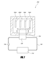
- FIG. 7 is an example thermal management system that includes a fluid conduit loop in accordance with certain embodiments described herein.
- Battery thermal management systems can be used to control temperatures and monitor conditions of batteries and arrays of batteries to prevent battery failure and/or safety related failure.
- a BTMS can improve the overall conditions of battery operation by both managing the thermal environment and also being sufficiently reliable so that overall system performance is not degraded.
- a BTMS may not reduce overall system reliability and not increase system operating cost by not including significant additional possible failure mechanisms to the system.
- the systems can be environmentally friendly and not contain materials that emit greenhouse gases such as refrigerants.
- a BTMS includes at least one battery or battery array.
- a battery thermal management system can be used to both heat and cool batteries and/or battery arrays.
- the battery thermal management system can be integrated with the at least one battery, the battery thermal management system can be integrated with an enclosure wherein the at least one battery is contained, or the thermal management system can be positioned in thermal communication with the at least one battery.
- a battery thermal management system includes one or more thermoelectric (TE) devices.
- the battery thermal management system can include a plurality of thermoelectric elements, at least one thermoelectric assembly, and/or at least one thermoelectric module.
- TE devices are solid state and do not utilize refrigerants to produce cooling, and some TE devices can produce both heating and cooling.
- battery thermal management systems can include a plurality of TE devices which can be configured to increase reliability over that of a conventional two phase refrigerant system, such as one employing refrigerant 134 A.
- a battery thermal management system 100 includes at least one battery and a plurality of thermoelectric devices in thermal communication with the at least one battery.
- FIG. 1 is a schematic circuit diagram of an example thermal management system 100 comprising a plurality of TE devices in accordance with certain embodiments described herein.
- the TE devices can be TE elements, TE assemblies, and/or TE modules.
- the plurality of TE devices includes a first group 104 a of TE devices and a second group 104 b of TE devices.
- the TE devices of the first TE group 104 a are in parallel electrical communication with one another, and the TE devices of the second TE group 104 b are in parallel electrical communication with one another.
- TE device 1 , TE device 2 , and TE device 3 are in parallel electrical communication with one another (having currents I 1 , I 2 , and I 3 , respectively, when the system 100 is operating) and TE device 4 , TE device 5 , and TE device 6 are in parallel electrical communication with one another (having currents I 4 , I 5 , and I 6 , respectively, when the system 100 is operating).
- the first TE group 104 a and the second TE group 104 b are in series electrical communication with one another.
- One or more additional TE groups 104 c can also be placed in series electrical communication with the first TE group 104 a and the second TE group 104 b.
- the battery thermal management system 100 can improve overall system cooling and heating reliability.
- the TE devices are configured so as to allow redundancy and eliminate common single point failure mechanisms within each TE group. For example, if TE device 1 fails open such that the TE device 1 is electrically open (e.g., the TE device is unable to pass electrical current), the current is rerouted through TE device 2 and TE device 3 which are electrically connected in parallel with the failed TE device 1 . If three or more TE devices are electrically connected together in parallel, more than one TE device could fail open, and the thermal management system 100 would still operate to provide cooling and/or heating.
- TE device 1 fails closed (e.g., the TE device 1 is more electrically conductive than TE device 2 and TE device 3 ), more of the electrical current will flow through the failed TE device 1 than TE device 2 and TE device 3 , and reduce or eliminate the cooling and/or heating of the TE device 2 and TE device 3 in the same parallel electrical connection.
- the TE group 2 that is in series electrical communication with TE group 1 will continue to function and provide heating and/or cooling. Failure of a TE device will degrade performance, but with sufficient numbers of TE devices, and the proper operating conditions, the thermal management system 100 can continue to function, albeit at a reduced heating and/or cooling capability if a TE device fails.
- performance of a thermal management system 100 with one or more failed TE devices can be substantially the same as that of a thermal management system 100 without any failed TE devices.
- Further examples of TE device redundancy are described in U.S. Patent Publication No. 2010/0031987, which is incorporated herein in its entirety by reference.
- FIG. 2 is a illustrative plot of operating electrical current as a function of the efficiency of energy conversion (COP) and the total thermal output of a TE device (Q c ).
- Points A and A′ are near the operating current that optimizes operating efficiency of the TE device (indicated by Point A) so that it will operate near its peak possible efficiency.
- Points B and B′ are a second operating current that is at 1.5 times the operating current of Points A and A′, and Points C and C′ are at a third operating current 3 times the operating current of Points A and A′.
- the dashed lines in FIG. 2 illustrate positions of the points relative to each other and relative to the x and y axes.
- a TE device can have a thermal output beyond peak operating efficiency by increasing electrical power even though efficiency may decrease.
- FIG. 3 is a schematic circuit diagram of an example thermal management system 300 that includes a plurality of TE devices in accordance with certain embodiments described herein.
- the thermal management system 300 in FIG. 3 also illustrates an example monitoring method to detect failure of a TE device. Diagnosing failure in a TE device of a thermal management system 300 can be measured through monitoring voltages and/or currents of the battery thermal management system 300 , either under transient or quasi-steady state conditions. Many other monitoring methods are also possible.
- the electrical configuration of the TE devices of the battery thermal management system 300 illustrated in FIG. 3 is similar to that illustrated in FIG. 1 .
- the battery thermal management system 300 includes a plurality of TE devices includes a first TE group 304 a and a second TE group 304 b .
- the TE devices of the first TE group 304 a are in parallel electrical communication with one another
- the TE devices of the second TE group 304 b are in parallel electrical communication with one another.
- TE device 1 , TE device 2 , and TE device 3 are in parallel electrical communication with one another and TE device 4 , TE device 5 , and TE device 6 are in parallel electrical communication with one another.
- the first TE group 304 a and the second TE group 304 b are in series electrical communication with one another.
- One or more additional TE groups 304 c can also be placed in series electrical communication with the first TE group 304 a and the second TE group 304 b.
- a method of thermally managing a battery thermal management system 300 includes providing a battery system comprising at least one battery and a plurality of thermoelectric devices in thermal communication with the at least one battery.
- the plurality of thermoelectric devices includes a first group 304 a of thermoelectric devices in series electrical communication with a second group 304 b of thermoelectric devices.
- the method includes measuring a first electrical voltage or current of the first group 304 a and measuring a second electrical voltage or current of the second group 304 b or both the first group 304 a and second group 304 b together.
- the method further includes monitoring an electrical comparison parameter dependent on the first electrical voltage or current and the second electrical voltage or current.
- the electrical comparison parameter comprises a value of the first electrical voltage or current divided by the second electrical voltage or current.
- the method further includes changing, in response to the electrical comparison parameter, at least one parameter of the battery system.
- the at least one parameter can be, for example, electrical power supplied to the plurality of thermoelectric devices.
- the thermal management system 300 can include two or more voltage and/or current meters or monitors for measuring the electrical voltage or current.
- a first meter 306 a can measure a first voltage and/or current (V 1 ) across the first group 304 a
- a second meter 306 b can measure a second voltage and/or current (V 2 ) across the second group 304 b
- a system meter 302 can measure a system voltage and/or current (V + ) across the first TE group 304 a , the second group 304 b , and the one or more additional TE groups 304 c .
- V 1 /V 2 , V 1 /V + , or V 2 /V + will change if one or more TE devices fail. Furthermore, even if the system voltage or current (V+) changes, the ratios V 1 /V 2 , V 1 /V + , and V 2 /V + would remain constant if one or more TE devices does not fail. Therefore, by monitoring V 1 and V 2 or V + , a failure of a TE device can be detected.
- FIG. 4A illustrates an example battery thermal management system 400 in accordance with certain embodiments described herein.
- a battery thermal management system 400 includes at least one battery 402 a - d and at least one thermoelectric device 404 in thermal communication with the at least one battery 402 a - d.
- the battery thermal management system 400 can include at least one first fluid conduit 406 that includes at least one inlet 408 configured to allow a first working fluid to enter and flow into the at least one first fluid conduit 406 and into thermal communication with the at least one thermoelectric device 404 .
- a heat exchanger 428 can transfer heat between the at least one thermoelectric device 404 and the first working fluid.
- the at least one first fluid conduit 406 also includes at least one outlet 410 configured to allow the first working fluid to exit and flow from the at least one first fluid conduit 406 and away from being in thermal communication with the at least one thermoelectric device 404 .
- the battery thermal management system 400 can further include at least one first flow control device 412 which directs the first working fluid through the at least one inlet 408 of the at least one first fluid conduit 406 , and at least one second flow control device 414 which directs the first working fluid through the at least one outlet 410 of the at least one first fluid conduit 406 .
- the at least one first flow control device 412 and the at least one second flow control device 414 are each separately operable from one another.
- the at least one first flow control device 412 pushes the first working fluid while the at least one second flow control device 414 pulls the first working fluid
- the at least one first flow control device 412 and the at least one second flow control device 414 are in series with one another or are in a push/pull configuration.
- the arrows in FIG. 4A illustrate the direction of flow of the working fluid.
- the at least one first flow control device 412 is positioned at an entrance of the at least one inlet 408 and the at least one second flow control device 414 is positioned at an exit of the at least one outlet 410 .
- the at least one first flow control device 412 is configured to push the first working fluid through the at least one inlet 408 and the at least one second flow control device 414 is configured to pull the first working fluid through at least one outlet 410 .
- the battery thermal management system 400 further includes a flow path for the first working fluid in which the first working fluid is in thermal communication with the at least one battery. The flow path, in some embodiments, receives the first working fluid from the at least one outlet 408 .
- the first working fluid is substantially thermally or electrically isolated from the at least one battery.
- the thermoelectric module 404 can include two sides including a cooler side and a hotter side. The first working fluid can be in thermal communication with only the cooler side or the hotter side, and the first working fluid can be substantially thermally isolated from the other side.
- the battery thermal management system 400 includes at least one second conduit 416 including at least one inlet 418 configured to allow a second working fluid to enter and flow into the at least one second conduit 416 and into thermal communication with the at least one thermoelectric device 404 .
- a heat exchanger 426 can transfer heat between the at least one thermoelectric device 404 and the second working fluid.
- the at least one second conduit 416 includes at least one outlet 420 configured to allow the second working fluid to exit and flow from the at least one second conduit 416 and away from being in thermal communication with the at least one thermoelectric device 404 .
- the battery thermal management system 400 includes at least one third flow control device 422 which directs the second working fluid through the at least one inlet 418 of the at least one second conduit 416 , and at least one fourth flow control device 424 which directs the second working fluid through the at least one outlet 420 of the at least one second conduit 416 .
- the at least one third flow control device 422 and the at least one fourth flow control device 424 are each separately operable from one another.
- the arrows in FIG. 4A illustrate the direction of flow of the first working fluid and the second working fluid.
- the first working fluid is substantially thermally isolated from the second working fluid.
- the first working fluid can be in thermal communication with a first side of the TE device 404 and the at least one battery 402 a - d
- the second working fluid can be in thermal communication with a second side of the TE device 404 different from the first side.
- the at least one battery 402 a - d can be selectively heated or cooled and the first working fluid and second working fluid can be correspondingly heated or cooled.
- the first side of the TE device 404 can be selected to heat or cool the at least one battery 402 a - d by heating or cooling the first working fluid and transferring heat between the at least one battery 402 a - d and the first working fluid, and the second working fluid can be correspondingly cooled if the first working fluid is heated or heated if the first working fluid is cooled.
- a method of thermally managing a battery thermal management system 400 includes transferring heat between at least one battery 402 a - d and at least one thermoelectric device 404 and flowing a working fluid through at least one first fluid conduit 406 in thermal communication with the at least one thermoelectric device 404 .
- the method further includes operating at least one first flow control device 412 to direct the working fluid to be in thermal communication with the at least one thermoelectric device 404 and operating at least one second flow control device 414 to direct the working fluid away from being in thermal communication with the at least one thermoelectric device 404 .
- the working fluid flows past, along, or around the at least one battery 402 a - d and heat is transferred from or to the at least one battery 402 a - d .
- the at least one battery 402 a - d is in substantially direct thermal communication with the TE device 404 and a working fluid does not transfer heat between the at least one battery 402 a - d and the TE device.
- the working fluid is substantially thermally isolated from the at least one battery 402 a - d and heat is transferred between the TE device 404 and working fluid.
- the working fluid can transfer waste heat away from the TE device 404 .
- FIG. 4B illustrates a fluid conduit 450 of a battery thermal management system in accordance with certain embodiments described herein.
- FIG. 4B is an example of flow control devices working in parallel while FIG. 4A is an example of flow control devices working in series.
- a battery thermal management system includes at least one battery and at least one thermoelectric device 452 in thermal communication with the at least one battery.
- the battery thermal management system further includes at least one fluid conduit 450 configured to allow a working fluid to flow therein and to transfer the working fluid into being in thermal communication with the at least one thermoelectric device 452 or away from being in thermal communication with the at least one thermoelectric device 452 .
- At least one first flow control device 454 directs the working fluid through the at least one fluid conduit 450
- at least one second flow control device 456 directs the working fluid through the at least one fluid conduit 450 .
- the at least one first flow control device 454 and the at least one second flow control device 456 are each separately operable from one another.
- the battery thermal management system also includes at least one divider portion 458 that is selectively positionable to block the working fluid from flowing between the at least one fluid conduit 450 and a selected one of the at least one first flow control device 454 and the at least one second flow control device 456 .
- a divider wall 460 can separate the at least one fluid conduit 450
- a flapper valve 462 can be positioned to block flow of the working fluid through either the first flow control device 454 or the at least one second flow control device 456 .
- FIG. 4B illustrates the flapper valve 462 blocking the flow through the at least one second flow control device 456
- the arrow 464 illustrates how the flapper valve 462 can rotate to block the flow of the working fluid from flowing through the at least one second flow control device 456 .
- the flapper valve 462 prevents back flow of the working fluid through an inoperative flow control device.
- the other arrows in FIG. 4B illustrate the direction of flow of the working fluid.
- the at least one divider portion 458 is positionable in multiple positions including: (1) a first position permitting the working fluid to flow between the at least one fluid conduit 450 and the at least one first flow control device 454 and permitting the working fluid to flow between the at least one fluid conduit 450 and the at least one second flow control device 456 , (2) a second position permitting the working fluid to flow between the at least one fluid conduit 450 and the at least one first flow control device 454 and blocking the working fluid from flowing between the at least one fluid conduit 450 and the at least one second flow control device 456 , and (3) a third position blocking the working fluid from flowing between the at least one fluid conduit 450 and the at least one first flow control device 454 and permitting the working fluid to flow between the at least one fluid conduit 450 and the at least one second flow control device 456 .
- the battery thermal management system can include both flow control devices in series and parallel.
- the at least one first flow control device 412 in FIG. 4A can include at least two first flow control devices.
- the battery thermal management system 400 can include at least one divider portion that is selectively positionable to block the working fluid from flowing between the at least one first fluid conduit 406 and a selected one of the at least one first flow control devices 412 .
- the divider portion separates at least a portion of the at least one inlet or the at least one outlet into at least two fluid channels comprising a first fluid channel and a second fluid channel.
- At least one flow control device of the at least two first flow control devices 412 directs the first working fluid through a first fluid channel, and at least one other flow control device of the at least two first flow control devices directs the first working fluid through a second fluid channel.
- Each of the at least two first flow control devices are each separately operable from one another.
- a method of thermally managing a battery system includes transferring heat between at least one battery and at least one thermoelectric device 452 and flowing a working fluid through a fluid conduit 450 in thermal communication with at least one thermoelectric device 452 .
- the method further includes directing the working fluid through the fluid conduit 450 using at least one first flow control device 454 and at least one second flow control device 456 and selectively inhibiting flow of the working fluid through a selected one of the at least one first flow control device 454 and the at least one second flow control device 456 .
- the battery thermal management system includes a plurality of power lines and/or redundancy with the power source or supply.
- the power supply can have several power conversion phases and energy filtering and/or storage components.
- Other methods of providing electrical power redundancy may also be provided. While performance such as ripple or drop out may occur as the result of a single failure, cooling or heating can continue to be provided.
- the TE device is put in close proximity to the battery.
- TE device may be attached, coupled, or integrated with the battery or a battery case.
- the cooling or heating side of a TE device can be advantageously positioned as close to the battery as possible.
- the cooling or heating power that may be lost through ducts or insulation can directly condition the system. Conditioning can include transferring heat to the battery to increase the temperature of the battery or transferring heat from the battery to decrease the temperature of the battery.
- the thermal power generated that leaks out of at least a portion of the ducts, conduits, or other mechanisms that direct a conditioned working fluid often still can be at least partially utilized.
- the conditioning surfaces such as ducts, tubes, etc. are positioned generally toward the working fluid, battery, or volume to be cooled, and the heat rejection side generally away from the conditioned surfaces and area.
- FIG. 7 illustrates an example battery thermal management system 700 that includes at least one conduit 760 (e.g. fluid circuit) in accordance with certain embodiments described herein.
- the battery thermal management system 700 includes at least one battery 702 a - d and at least one thermoelectric device 704 in thermal communication with the at least one battery 702 a - d .
- the battery thermal management system 700 includes at least one flow control device 740 such as a fluid pump.
- the at least one flow control device 740 circulates the working fluid through the at least one conduit 760 . In some embodiments, the working fluid is re-circulated through the at least one conduit 760 .
- the working fluid may flow into thermal communication with the at least one thermoelectric device 704 , and the working fluid may flow away from being in thermal communication with the at least one thermoelectric device 704 .
- at least one heat exchanger 726 may be in thermal communication with the at least one thermoelectric device 704 .
- the working fluid may flow into thermal communication with the at least one heat exchanger 726 and the working fluid may flow away from being in thermal communication with the at least one heat exchanger 726 .
- the same working fluid may flow into and away from being in thermal communication with the at least one thermoelectric device 704 more than once.
- the at least one conduit 760 can be a fluid loop.
- the battery thermal management system 700 includes a fluid reservoir or source 750 fluidly coupled with the at least one conduit 760 .
- the fluid reservoir or source 750 may heat or cool the working fluid.
- the fluid reservoir or source 750 can be connected to other sources of heat such as an engine powertrain fluid to provide further heat to the at least one battery 702 a - d .
- the fluid reservoir or source 750 can include a radiator such as a vehicle chassis or an auxiliary radiator to reject heat from the at least one battery 702 a - d through the at least one TE device 704 .
- the working fluid can be any type of fluid such as liquid, gas, or multipurpose solid-liquid convection medium.
- the working fluid comprises a mixture of water and glycol.
- a liquid working fluid may have a greater thermal capacity than a gas working fluid, which can result in greater efficiency for the TE device 704 .
- many heat exchangers with fins, etc. have a higher thermal coefficient of performance or a higher heat transfer rate with the working fluid when the working fluid is a liquid than when the working fluid is a gas (e.g., air).
- a higher thermal coefficient of performance can reduce the temperature drop across the interface between the working fluid and the heat exchanger 726 .
- the total temperature drop between the TE device 704 and the working fluid can be reduced.
- a lower temperature drop can result in higher efficiency for the TE device 704 and/or higher temperature differential across the TE device 704 .
- FIG. 5 is a schematic circuit diagram of an example thermal management system 500 comprising a plurality of TE devices configured to change thermal power output by changing the electrical configuration of the TE devices in accordance with certain embodiments described herein. For example, under extreme ambient heat (or cold), it may be desirable to increase the current through the TE devices to increase cooling (or heating) thermal power output.
- the TE devices can be TE elements, TE assemblies, or TE modules.
- At battery thermal management system 500 includes at least one battery and a plurality of thermoelectric assemblies 502 a , 502 b in thermal communication with the at least one battery.
- Each thermoelectric assembly 502 a , 502 b includes a plurality of thermoelectric devices.
- a first thermoelectric assembly 502 a of the plurality of thermoelectric assemblies is in electrical communication with a second thermoelectric assembly 502 b of the plurality of thermoelectric assemblies.
- a circuit 506 is in electrical communication with the first thermoelectric assembly 502 a and the second thermoelectric assembly 502 b .
- the circuit 506 can be configured to be selectively switchable to place the first thermoelectric assembly 502 a and the second thermoelectric assembly 502 b either in series electrical communication or parallel electrical communication with one another.
- thermoelectric elements of the first thermoelectric assembly 502 a can be in series electrical communication and/or in parallel electrical communication with one another
- at least some of the plurality of thermoelectric elements of the second thermoelectric assembly 502 b can be in series electrical communication and/or parallel electrical communication with one another
- the first thermoelectric assembly 502 a can include a first plurality of TE groups 504 a , 504 b
- the second thermoelectric assembly 502 b can include a second plurality of TE groups 504 c , 504 d .
- a first TE group 504 a of TE devices are in parallel electrical communication with one another
- a second TE group 504 b of TE devices are in parallel electrical communication with one another
- a third TE group 504 c of TE devices are in parallel electrical communication with one another
- a fourth TE group 504 d of TE devices are in parallel electrical communication with one another.
- the first TE group 504 a is in series electrical communication with the second TE group 504 b
- the third group 504 c is in series electrical communication with the fourth TE group 504 d .
- Similar features as discussed with regard to FIG. 1 can be included with certain embodiments that include a circuit 506 that can be configured to be selectively switchable to place the first thermoelectric assembly 502 a and the second thermoelectric assembly 502 b either in series electrical communication or parallel electrical communication with one another.
- the solid lines in the circuit 506 of FIG. 5 illustrate a first circuit position wherein the first TE group 504 a , the second TE group 504 b , the third TE group 504 c , and the fourth TE group 504 d are in series electrical communication with one another.
- the dotted lines in the circuit 506 of FIG. 5 illustrate a first circuit position wherein the first TE group 504 a , the second TE group 504 b , the third TE group 504 c , and the fourth TE group 504 d are in series electrical communication with one another.
- thermoelectric assembly 502 a e.g., the first TE group 504 a and the second TE group 504 b
- the first thermoelectric assembly 502 a is in parallel electrical communication with the second thermoelectric assembly 502 b (e.g., the third TE group 504 c and the fourth TE group 504 d ).
- a method of thermally managing a battery thermal management system 500 includes providing a battery system including at least one battery and a plurality of thermoelectric assemblies 502 a , 502 b in thermal communication with the at least one battery. The method further includes measuring at least one parameter of the battery system and switching, in response to the at least one parameter, a first thermoelectric assembly 502 a of the plurality of thermoelectric assemblies between being in parallel or series electrical communication with a second thermoelectric assembly 502 b of the plurality of thermoelectric assemblies.
- the at least one parameter can, for example, include temperature of the at least one battery and/or the battery system. Additional parameters are discussed in the following sections.
- the plurality of thermoelectric assemblies are selectively operable to either heat or cool the at least one battery.
- the circuit 506 may also be selectively switchable to adjust current flow through the first thermoelectric assembly 502 a and the second thermoelectric assembly 502 b .
- voltage of the circuit 506 can be altered to cause more or less current to flow through the TE devices in order to modify heat pumping capacity of the TE devices.
- the performance of the BTMS can be altered by, for example, altering fan and/or pump operation to change working fluid flow conditions such as flow rate and/or flow paths.
- the BTMS can further include a controller to control the circuit 506 , flow control devices, etc. of the BTMS.
- the controller may be integrated with the BTMS or may be an external controller.
- FIG. 6 illustrates examples of a plurality of monitoring systems 630 a - d and their locations in a BTMS 600 in accordance with certain embodiments described herein.
- a TE device 604 can include one or more monitors or monitoring systems 630 a - d including TE device monitoring systems 630 a , battery monitoring systems 630 b , working fluid monitoring systems 630 c , and flow control device monitoring systems 630 d that can measure at least one parameter.
- the monitoring systems 630 a - d can be integrated within, on a surface of, neighboring, or within proximity to measure the at least one parameter of the TE device 604 , battery 602 a - d , working fluid, flow control device 612 , etc.
- components such as fans, circuit elements, battery parts, batteries, components of a battery, battery arrays and/or BTMS can include monitoring systems 630 a - d .
- a monitoring system 630 a - d can include one or more temperature sensors. Temperature sensors can include thermistors, positive temperature coefficient-thermal cutoffs, thermocouples and other temperature sensing and temperature activated devices. Temperatures that can be monitored can include, for example, working fluid, working fluid inlet, working fluid inlet temperature, working fluid outlet, working fluid outlet temperature, inlet fluid temperatures, conditioned fluid temperatures, temperature differentials between fluid inlets and outlets, temperature between the conditioning side and the heat rejection side, conditioning side temperature measurement, heat rejection side temperature measurement, fluid control device (e.g., pump or fan) temperatures, fluid control device temperature measurement. Furthermore, multiple measurements at several locations and any other combination of temperature measurements may be made.
- Temperature sensors can include thermistors, positive temperature coefficient-thermal cutoffs, thermocouples and other temperature sensing and temperature activated devices. Temperatures that can be monitored can include, for example, working fluid, working fluid inlet, working fluid inlet temperature, working fluid outlet, working fluid outlet temperature, inlet fluid temperatures, conditioned fluid temperatures, temperature differential
- fluid control device speeds, fluid control device voltages and/or currents, fluid flow rates at one or multiple locations, emissions of fluids from the battery, battery array or any other device, fluid velocities, battery voltages and/or currents, battery or battery dimensions and/or dimensional change can be monitored.
- at least one monitoring system can include circuit sensors to monitor electrical communication of circuits and/or TE devices 604 .
- Monitoring systems can also provide a signal or be in communication with a control device.
- the control device may measure the at least one parameter that is monitored, and the control device may, in response to the at least one parameter, cause at least one component of the BTMS to change.
- the control device may apply an algorithm to the measured parameter to determine what response, if any, the control device may apply to a component of the BTMS.
- Control devices can include devices that acquire sensor data, perform calculations based on the sensor data, and cause at least one component of the BTMS to change such as valves, blower speed controllers and other devices to actuate or reduce/increase flow rate, etc., and parametric controllers.
- At least one parameter can be monitored to determine the exposure the battery, battery array or BTMS may have experienced and any other operating history of the BTMS that may be useful.
- the monitoring can be done for warranty, determining charge cycle (e.g., optimizing speed of charge), state of operation, safety, optimizing performance, increasing longevity, establishing operational history, indicating failure, modifying battery charge schedules based on measured values, indicating impending degradation of performance and any other diagnostic measurements.
- the BTMS may contain control, communication, computational, storage and/or processing capabilities to act upon the information collected by components of the BTMS and/or other systems in communication with the BTMS and communicate results of information processed by the BTMS and/or other systems.
- the BTMS may contain electronic signal processing hardware, input/output devices, permanent recording hardware or any other useful electronic or other signal processing equipment.
- the system may have the capacity to take actions, send signals, receive signals, store information, perform logic functions, control temperatures, fan and/or pump, TE, and any other subsystem function, modify operation and/or perform any other function to manage battery or battery array operation.
Abstract
Description
Claims (21)
Priority Applications (3)
| Application Number | Priority Date | Filing Date | Title |
|---|---|---|---|
| US14/639,921 US9666914B2 (en) | 2009-05-18 | 2015-03-05 | Thermoelectric-based battery thermal management system |
| US15/499,507 US20170294692A1 (en) | 2009-05-18 | 2017-04-27 | Battery thermal management system |
| US16/563,550 US11264655B2 (en) | 2009-05-18 | 2019-09-06 | Thermal management system including flapper valve to control fluid flow for thermoelectric device |
Applications Claiming Priority (3)
| Application Number | Priority Date | Filing Date | Title |
|---|---|---|---|
| US17932609P | 2009-05-18 | 2009-05-18 | |
| US12/782,532 US8974942B2 (en) | 2009-05-18 | 2010-05-18 | Battery thermal management system including thermoelectric assemblies in thermal communication with a battery |
| US14/639,921 US9666914B2 (en) | 2009-05-18 | 2015-03-05 | Thermoelectric-based battery thermal management system |
Related Parent Applications (1)
| Application Number | Title | Priority Date | Filing Date |
|---|---|---|---|
| US12/782,532 Continuation US8974942B2 (en) | 2009-05-18 | 2010-05-18 | Battery thermal management system including thermoelectric assemblies in thermal communication with a battery |
Related Child Applications (1)
| Application Number | Title | Priority Date | Filing Date |
|---|---|---|---|
| US15/499,507 Continuation US20170294692A1 (en) | 2009-05-18 | 2017-04-27 | Battery thermal management system |
Publications (2)
| Publication Number | Publication Date |
|---|---|
| US20150244042A1 US20150244042A1 (en) | 2015-08-27 |
| US9666914B2 true US9666914B2 (en) | 2017-05-30 |
Family
ID=42320084
Family Applications (6)
| Application Number | Title | Priority Date | Filing Date |
|---|---|---|---|
| US12/782,532 Active 2031-06-02 US8974942B2 (en) | 2009-05-18 | 2010-05-18 | Battery thermal management system including thermoelectric assemblies in thermal communication with a battery |
| US13/153,241 Abandoned US20110236731A1 (en) | 2009-05-18 | 2011-06-03 | Battery Thermal Management System |
| US13/559,530 Abandoned US20120285758A1 (en) | 2009-05-18 | 2012-07-26 | Thermoelectric-based thermal management systems |
| US14/639,921 Active 2030-08-04 US9666914B2 (en) | 2009-05-18 | 2015-03-05 | Thermoelectric-based battery thermal management system |
| US15/499,507 Abandoned US20170294692A1 (en) | 2009-05-18 | 2017-04-27 | Battery thermal management system |
| US16/563,550 Active 2030-11-08 US11264655B2 (en) | 2009-05-18 | 2019-09-06 | Thermal management system including flapper valve to control fluid flow for thermoelectric device |
Family Applications Before (3)
| Application Number | Title | Priority Date | Filing Date |
|---|---|---|---|
| US12/782,532 Active 2031-06-02 US8974942B2 (en) | 2009-05-18 | 2010-05-18 | Battery thermal management system including thermoelectric assemblies in thermal communication with a battery |
| US13/153,241 Abandoned US20110236731A1 (en) | 2009-05-18 | 2011-06-03 | Battery Thermal Management System |
| US13/559,530 Abandoned US20120285758A1 (en) | 2009-05-18 | 2012-07-26 | Thermoelectric-based thermal management systems |
Family Applications After (2)
| Application Number | Title | Priority Date | Filing Date |
|---|---|---|---|
| US15/499,507 Abandoned US20170294692A1 (en) | 2009-05-18 | 2017-04-27 | Battery thermal management system |
| US16/563,550 Active 2030-11-08 US11264655B2 (en) | 2009-05-18 | 2019-09-06 | Thermal management system including flapper valve to control fluid flow for thermoelectric device |
Country Status (8)
| Country | Link |
|---|---|
| US (6) | US8974942B2 (en) |
| EP (1) | EP2433321B1 (en) |
| JP (1) | JP5496324B2 (en) |
| KR (4) | KR102112970B1 (en) |
| CN (2) | CN102439756B (en) |
| MX (1) | MX2011012238A (en) |
| RU (1) | RU2011143856A (en) |
| WO (1) | WO2010135371A2 (en) |
Cited By (11)
| Publication number | Priority date | Publication date | Assignee | Title |
|---|---|---|---|---|
| US20160356507A1 (en) * | 2014-08-29 | 2016-12-08 | Qingdao Haier Air Conditionaer General Corp., Ltd. | Wall-mounted air conditioner indoor unit |
| US10170811B2 (en) | 2013-01-14 | 2019-01-01 | Gentherm Incorporated | Thermoelectric-based thermal management of electrical devices |
| US10236547B2 (en) | 2013-10-29 | 2019-03-19 | Gentherm Incorporated | Battery thermal management systems including heat spreaders with thermoelectric devices |
| US10270141B2 (en) | 2013-01-30 | 2019-04-23 | Gentherm Incorporated | Thermoelectric-based thermal management system |
| US10337770B2 (en) | 2011-07-11 | 2019-07-02 | Gentherm Incorporated | Thermoelectric-based thermal management of electrical devices |
| US20190356029A1 (en) * | 2018-05-18 | 2019-11-21 | Lee Fei Chen | Charging device having thermoelectric module |
| US10700393B2 (en) | 2014-09-12 | 2020-06-30 | Gentherm Incorporated | Graphite thermoelectric and/or resistive thermal management systems and methods |
| US11152557B2 (en) | 2019-02-20 | 2021-10-19 | Gentherm Incorporated | Thermoelectric module with integrated printed circuit board |
| US11264655B2 (en) | 2009-05-18 | 2022-03-01 | Gentherm Incorporated | Thermal management system including flapper valve to control fluid flow for thermoelectric device |
| US11592210B2 (en) | 2020-06-08 | 2023-02-28 | Max Moskowitz | System and method for providing heated water to sabbath observers |
| US11670813B2 (en) | 2019-04-01 | 2023-06-06 | Applied Thermoelectric Solutions, LLC | Electrically insulative and thermally conductive parallel battery cooling and temperature control system |
Families Citing this family (63)
| Publication number | Priority date | Publication date | Assignee | Title |
|---|---|---|---|---|
| US7273981B2 (en) * | 2001-02-09 | 2007-09-25 | Bsst, Llc. | Thermoelectric power generation systems |
| US7426835B2 (en) | 2001-08-07 | 2008-09-23 | Bsst, Llc | Thermoelectric personal environment appliance |
| US20110209740A1 (en) * | 2002-08-23 | 2011-09-01 | Bsst, Llc | High capacity thermoelectric temperature control systems |
| US7380586B2 (en) | 2004-05-10 | 2008-06-03 | Bsst Llc | Climate control system for hybrid vehicles using thermoelectric devices |
| US7743614B2 (en) | 2005-04-08 | 2010-06-29 | Bsst Llc | Thermoelectric-based heating and cooling system |
| US8783397B2 (en) | 2005-07-19 | 2014-07-22 | Bsst Llc | Energy management system for a hybrid-electric vehicle |
| US7779639B2 (en) | 2006-08-02 | 2010-08-24 | Bsst Llc | HVAC system for hybrid vehicles using thermoelectric devices |
| US20100155018A1 (en) | 2008-12-19 | 2010-06-24 | Lakhi Nandlal Goenka | Hvac system for a hybrid vehicle |
| CN101720414B (en) | 2007-05-25 | 2015-01-21 | Bsst有限责任公司 | System and method for distributed thermoelectric heating and colling |
| US9555686B2 (en) | 2008-10-23 | 2017-01-31 | Gentherm Incorporated | Temperature control systems with thermoelectric devices |
| US9447994B2 (en) | 2008-10-23 | 2016-09-20 | Gentherm Incorporated | Temperature control systems with thermoelectric devices |
| US20100101239A1 (en) | 2008-10-23 | 2010-04-29 | Lagrandeur John | Multi-mode hvac system with thermoelectric device |
| CN104914896B (en) | 2009-05-18 | 2017-06-13 | 詹思姆公司 | temperature control system with thermoelectric device |
| EP2443687B1 (en) | 2009-06-18 | 2017-05-31 | Johnson Controls Advanced Power Solutions LLC | Battery module having a cell tray with thermal management features |
| EP2567424B1 (en) | 2010-05-07 | 2015-08-19 | Siemens Aktiengesellschaft | Electrical energy store with cooling device |
| US20120203421A1 (en) * | 2011-02-07 | 2012-08-09 | GM Global Technology Operations LLC | Data association for vehicles |
| DE102011004721A1 (en) * | 2011-02-25 | 2012-08-30 | Behr Gmbh & Co. Kg | Temperierungsvorrichtung and method for controlling the temperature of an energy storage |
| US9553460B2 (en) * | 2011-03-31 | 2017-01-24 | Elite Power Solutions Llc | Wireless battery management system |
| JP2013025948A (en) * | 2011-07-19 | 2013-02-04 | Toyota Industries Corp | Battery module |
| JP5365715B2 (en) * | 2012-03-12 | 2013-12-11 | 株式会社豊田自動織機 | Battery pack |
| US9415700B2 (en) * | 2012-09-04 | 2016-08-16 | GM Global Technology Operations LLC | Battery thermal system and diagnostic method |
| KR101371739B1 (en) * | 2012-09-07 | 2014-03-12 | 기아자동차(주) | Battery system |
| KR101877996B1 (en) * | 2012-09-07 | 2018-07-16 | 현대자동차주식회사 | Battery system |
| KR101355616B1 (en) * | 2012-10-23 | 2014-01-27 | 기아자동차주식회사 | System and method for managing battery |
| DE102012224486A1 (en) * | 2012-12-28 | 2014-04-10 | Behr Gmbh & Co. Kg | Heat exchanger |
| CN103219831A (en) * | 2013-03-22 | 2013-07-24 | 天津市松正电动汽车技术股份有限公司 | Air-cooling motor and new energy automobile battery heating device |
| JP6024562B2 (en) * | 2013-03-28 | 2016-11-16 | トヨタ自動車株式会社 | Battery temperature control system |
| US9799933B2 (en) * | 2013-08-28 | 2017-10-24 | Robert Bosch Gmbh | Solid state battery with integrated rate booster |
| WO2015188784A1 (en) * | 2014-06-12 | 2015-12-17 | Mediatek Inc. | Thermal management method and electronic system with thermal management mechanism |
| KR101829093B1 (en) * | 2014-10-22 | 2018-03-29 | 주식회사 엘지화학 | Cooling air flow control system and method for battery system |
| CN105633484A (en) * | 2014-10-31 | 2016-06-01 | 中华汽车工业股份有限公司 | Battery temperature managing system of electrombile |
| US10581251B2 (en) * | 2014-12-18 | 2020-03-03 | Fca Us Llc | Battery pack active thermal management system |
| DE112015005666T5 (en) | 2014-12-19 | 2017-09-14 | Gentherm Incorporated | Thermal conditioning systems and methods for vehicle areas |
| US9627725B2 (en) | 2015-04-28 | 2017-04-18 | Lg Chem, Ltd. | Battery pack |
| US10290911B2 (en) * | 2015-05-18 | 2019-05-14 | Toyota Motor Engineering & Manufacturing North America, Inc. | Cooling loops and vehicles incorporating the same |
| DE112016002619T5 (en) | 2015-06-10 | 2018-04-05 | Gentherm Inc. | A vehicle battery thermoelectric device having an integrated cold plate assembly and methods of mounting the same |
| EP3331054A4 (en) | 2015-07-27 | 2019-02-27 | Contemporary Amperex Technology Co., Limited | Battery group heat management module |
| JP2017045970A (en) * | 2015-08-29 | 2017-03-02 | 京セラ株式会社 | Thermoelectric module |
| US10625566B2 (en) | 2015-10-14 | 2020-04-21 | Gentherm Incorporated | Systems and methods for controlling thermal conditioning of vehicle regions |
| US10471803B2 (en) * | 2016-01-27 | 2019-11-12 | Ford Global Technologies, Llc | Systems and methods for thermal battery control |
| US10714956B2 (en) | 2016-04-05 | 2020-07-14 | Adam Gleason | Apparatus, system, and method for battery charging |
| US10361577B2 (en) | 2016-04-05 | 2019-07-23 | Adam Gleason | Battery charging and cooling apparatus |
| CN106711537A (en) * | 2016-11-16 | 2017-05-24 | 浙江超威创元实业有限公司 | Lithium battery with inside structure matched with heat pipe heat radiation mode |
| GB2556881A (en) * | 2016-11-23 | 2018-06-13 | Ford Global Tech Llc | A method of adaptively controlling an electrical system having a lithium-ion battery |
| WO2018210363A1 (en) * | 2017-05-17 | 2018-11-22 | Gentherm Gmbh | Temperature management device for vehicle batteries |
| WO2019071132A1 (en) * | 2017-10-06 | 2019-04-11 | Norma U.S. Holding Llc | Battery thermal management manifold segment and assembly thereof |
| CN109980313A (en) * | 2017-12-27 | 2019-07-05 | 河南森源重工有限公司 | A kind of the heat management control method and system of battery pack |
| DE102018205363A1 (en) * | 2018-04-10 | 2019-10-10 | Bayerische Motoren Werke Aktiengesellschaft | Device for tempering an electrical energy store |
| EP3588667A1 (en) * | 2018-06-25 | 2020-01-01 | APR Technologies AB | Immersion cooling of battery device |
| CN109119726A (en) * | 2018-09-27 | 2019-01-01 | 蔚来汽车有限公司 | The temperature control equipment and method of battery pack |
| DE102019003534A1 (en) * | 2019-05-21 | 2020-11-26 | Gentherm Gmbh | Temperature control device for an energy store |
| CN110576746A (en) * | 2019-09-04 | 2019-12-17 | 陕西法士特齿轮有限责任公司 | Energy management method for pure electric vehicle |
| KR102287330B1 (en) | 2019-11-15 | 2021-08-06 | 삼성에스디아이 주식회사 | Fan fault detection device |
| FR3106937A1 (en) * | 2020-02-05 | 2021-08-06 | Valeo Systemes Thermiques | Device for regulating the temperature of an electrical element capable of releasing heat in operation and battery pack comprising such a device |
| KR20220150004A (en) * | 2021-05-03 | 2022-11-10 | 에스케이온 주식회사 | Secondary battery |
| CN113381096B (en) * | 2021-06-09 | 2022-10-14 | 上海理工大学 | Real-time optimization battery thermal management system based on cooling path |
| KR102463150B1 (en) * | 2022-02-09 | 2022-11-08 | (주)프라즈마 사이언스 | Battery module and battery module management system for enhancing physical safety and chemical safety |
| WO2023183802A2 (en) * | 2022-03-21 | 2023-09-28 | Georgia Tech Research Corporation | Battery thermal management systems and methods |
| EP4276974A1 (en) * | 2022-05-09 | 2023-11-15 | Volvo Truck Corporation | A cooling system for one or more battery cells of an electric battery |
| DE102022002190A1 (en) | 2022-06-16 | 2023-12-21 | Voss Automotive Gmbh | Thermal management arrangement and vehicle with at least one such thermal management arrangement |
| EP4292840A2 (en) | 2022-06-16 | 2023-12-20 | Voss Automotive GmbH | Thermal management assembly and vehicle having at least one such thermal management assembly |
| DE102022002189A1 (en) | 2022-06-16 | 2023-12-21 | Voss Automotive Gmbh | Thermal management arrangement and vehicle with at least one such thermal management arrangement |
| EP4292841A2 (en) | 2022-06-16 | 2023-12-20 | Voss Automotive GmbH | Thermal management assembly and vehicle having at least one such thermal management assembly |
Citations (351)
| Publication number | Priority date | Publication date | Assignee | Title |
|---|---|---|---|---|
| SU184886A1 (en) | А. Л. Вайнер | LIQUID COOLER | ||
| US413136A (en) | 1889-10-15 | dewey | ||
| US2363168A (en) | 1942-10-08 | 1944-11-21 | Eaton Mfg Co | Heater |
| US2499901A (en) | 1946-08-31 | 1950-03-07 | Brown Fintube Co | Fin tube assembly |
| US2944404A (en) | 1957-04-29 | 1960-07-12 | Minnesota Mining & Mfg | Thermoelectric dehumidifying apparatus |
| US2949014A (en) | 1958-06-02 | 1960-08-16 | Whirlpool Co | Thermoelectric air conditioning apparatus |
| US2984077A (en) | 1958-10-24 | 1961-05-16 | Collins Radio Co | Method of using the peltier effect for cooling equipment |
| US2997514A (en) | 1958-03-11 | 1961-08-22 | Whirlpool Co | Refrigerating apparatus |
| US3085405A (en) | 1961-04-06 | 1963-04-16 | Westinghouse Electric Corp | Thermoelectric air conditioning apparatus for a protective garment |
| US3125860A (en) | 1962-07-12 | 1964-03-24 | Thermoelectric cooling system | |
| US3136577A (en) | 1961-08-02 | 1964-06-09 | Stevenson P Clark | Seat temperature regulator |
| US3137142A (en) | 1962-09-24 | 1964-06-16 | Borg Warner | Heat transfer system as it pertains to thermoelectrics |
| US3138934A (en) | 1962-11-19 | 1964-06-30 | Kysor Industrial Corp | Thermoelectric heating and cooling system for vehicles |
| US3196620A (en) | 1964-02-10 | 1965-07-27 | Thore M Elfving | Thermoelectric cooling system |
| US3212275A (en) | 1964-08-20 | 1965-10-19 | American Radiator & Standard | Thermoelectric heat pump |
| US3213630A (en) | 1964-12-18 | 1965-10-26 | Westinghouse Electric Corp | Thermoelectric apparatus |
| US3236056A (en) | 1965-01-11 | 1966-02-22 | Edward L Phillips | Apparatus for cooling automobiles and the like |
| US3252504A (en) | 1964-12-30 | 1966-05-24 | Borg Warner | Thermoelectric air conditioning systems |
| GB1040485A (en) | 1962-06-28 | 1966-08-24 | Licentia Gmbh | Improvements relating to refrigerating equipment |
| US3391727A (en) | 1966-11-14 | 1968-07-09 | Ford Motor Co | Disc type rotary heat exchanger |
| DE1301454B (en) | 1962-03-07 | 1969-08-21 | Eigner Otto | Room cooling unit |
| US3527621A (en) | 1964-10-13 | 1970-09-08 | Borg Warner | Thermoelectric assembly |
| US3561224A (en) | 1967-06-07 | 1971-02-09 | Trw Inc | Thermoelectric temperature controller |
| US3599437A (en) | 1970-03-03 | 1971-08-17 | Us Air Force | Thermoelectric cooling device |
| US3635037A (en) | 1969-09-02 | 1972-01-18 | Buderus Eisenwerk | Peltier-effect heat pump |
| US3681929A (en) | 1969-12-10 | 1972-08-08 | Hans Schering | Thermoelectric device |
| LU66619A1 (en) | 1971-12-10 | 1973-02-08 | ||
| US3779307A (en) | 1970-11-26 | 1973-12-18 | Su Deutsche Kuhlerfab Julius F | Heating and cooling system for motor vehicles |
| US3817043A (en) | 1972-12-07 | 1974-06-18 | Petronilo C Constantino & Ass | Automobile air conditioning system employing thermoelectric devices |
| DE2319155A1 (en) | 1973-04-16 | 1974-10-31 | Daimler Benz Ag | EMISSION-FREE HEATING OF VEHICLES WITH HYBRID DRIVE |
| US3885126A (en) | 1972-06-07 | 1975-05-20 | Nissan Motor | Electric heat accumulator unit |
| US4038831A (en) | 1975-06-27 | 1977-08-02 | Air Industrie | Thermoelectric installations |
| US4051691A (en) | 1973-12-10 | 1977-10-04 | Dawkins Claude W | Air conditioning apparatus |
| US4065936A (en) | 1976-06-16 | 1978-01-03 | Borg-Warner Corporation | Counter-flow thermoelectric heat pump with discrete sections |
| US4193271A (en) | 1977-07-07 | 1980-03-18 | Honigsbaum Richard F | Air conditioning system having controllably coupled thermal storage capability |
| US4229687A (en) | 1979-05-07 | 1980-10-21 | Utah Research & Development Corporation | Temperature maintained battery system |
| JPS5618231A (en) | 1979-07-25 | 1981-02-20 | Masahiro Morita | Cool sleep system |
| US4280330A (en) | 1977-09-19 | 1981-07-28 | Verdell Harris | Vehicle heating and cooling system |
| US4314008A (en) | 1980-08-22 | 1982-02-02 | General Electric Company | Thermoelectric temperature stabilized battery system |
| US4324845A (en) | 1980-06-30 | 1982-04-13 | Communications Satellite Corp. | Metal-oxide-hydrogen cell with variable conductant heat pipe |
| US4444851A (en) | 1982-06-28 | 1984-04-24 | Energy Research Corporation | Fuel cell stack |
| US4448157A (en) | 1982-03-08 | 1984-05-15 | Eckstein Robert J | Auxiliary power unit for vehicles |
| US4494380A (en) | 1984-04-19 | 1985-01-22 | Bilan, Inc. | Thermoelectric cooling device and gas analyzer |
| US4531379A (en) | 1983-10-14 | 1985-07-30 | Diefenthaler Jr Robert E | Auxiliary power system for vehicle air conditioner and heater |
| US4658599A (en) | 1984-05-28 | 1987-04-21 | Mitsubishi Denki Kabushiki Kaisha | Cooler for automotive use |
| US4665707A (en) | 1985-08-26 | 1987-05-19 | Hamilton A C | Protection system for electronic apparatus |
| US4665971A (en) | 1984-06-04 | 1987-05-19 | Diesel Kiki Co., Ltd. | Air conditioner system for automobiles |
| US4707995A (en) | 1981-06-18 | 1987-11-24 | Geophysical Engineering Company | Apparatus and method for controlling temperature and humidity within an enclosure |
| US4753682A (en) | 1985-09-03 | 1988-06-28 | Ital Idee S.R.L. | Apparatus of thermoelectric effect for current generation in internal combustion engine vehicles and the like, with recovery of the externally dissipated heat |
| US4823554A (en) | 1987-04-22 | 1989-04-25 | Leonard Trachtenberg | Vehicle thermoelectric cooling and heating food and drink appliance |
| JPH01131830A (en) | 1987-11-14 | 1989-05-24 | Matsushita Electric Works Ltd | Dehumidifier |
| US4848090A (en) | 1988-01-27 | 1989-07-18 | Texas Instruments Incorporated | Apparatus for controlling the temperature of an integrated circuit package |
| JPH01200122A (en) | 1988-02-04 | 1989-08-11 | Fujita Corp | Local cooling heating device |
| US4858069A (en) | 1988-08-08 | 1989-08-15 | Gte Spacenet Corporation | Electronic housing for a satellite earth station |
| US4865929A (en) | 1987-10-23 | 1989-09-12 | Asea Brown Boveri Aktiengesellschaft | High-temperature storage battery |
| JPH01281344A (en) | 1988-02-02 | 1989-11-13 | Sanei Corp:Kk | Dehumidifying device |
| US4905475A (en) | 1989-04-27 | 1990-03-06 | Donald Tuomi | Personal comfort conditioner |
| US4907060A (en) | 1987-06-02 | 1990-03-06 | Nelson John L | Encapsulated thermoelectric heat pump and method of manufacture |
| US4922998A (en) | 1987-11-05 | 1990-05-08 | Peter Carr | Thermal energy storage apparatus |
| US4922721A (en) | 1989-05-01 | 1990-05-08 | Marlow Industries, Inc. | Transporter unit with communication media environmental storage modules |
| US4947735A (en) | 1988-05-27 | 1990-08-14 | Valeo | Distribution box for a heating and/or air conditioning apparatus, especially for an automotive vehicle |
| EP0389407A1 (en) | 1989-03-20 | 1990-09-26 | United Technologies Corporation | Space suit cooling apparatus |
| US4988847A (en) | 1986-09-02 | 1991-01-29 | Argos Harry J | Electrically heated air blower unit for defogging bathroom mirrors |
| US4999576A (en) | 1989-07-31 | 1991-03-12 | General Electric Company | Electrical-energy-supplying device having an extended storage life |
| US5015545A (en) | 1990-01-03 | 1991-05-14 | General Motors Corporation | Method and apparatus for cooling an array of rechargeable batteries |
| US5029446A (en) | 1989-08-15 | 1991-07-09 | Kabushiki Kaisha B & D Japan | Electronic compact refrigerator |
| US5038569A (en) | 1989-04-17 | 1991-08-13 | Nippondenso Co., Ltd. | Thermoelectric converter |
| US5042566A (en) | 1989-05-19 | 1991-08-27 | Siemens Aktiengesellschaft | Heating or air conditioning system for a motor vehicle |
| US5071652A (en) | 1990-12-11 | 1991-12-10 | Globe-Union Inc. | Metal oxide hydrogen battery having improved heat transfer properties |
| US5092129A (en) | 1989-03-20 | 1992-03-03 | United Technologies Corporation | Space suit cooling apparatus |
| US5097829A (en) | 1990-03-19 | 1992-03-24 | Tony Quisenberry | Temperature controlled cooling system |
| JPH04103925A (en) | 1990-08-23 | 1992-04-06 | Nippondenso Co Ltd | Dehumidifier |
| US5111664A (en) | 1989-05-29 | 1992-05-12 | Samsung Electronics Co., Ltd. | Portable refrigerating/heating apparatus |
| US5121047A (en) | 1990-06-01 | 1992-06-09 | Motorola, Inc. | Battery charging system |
| US5119640A (en) | 1990-10-22 | 1992-06-09 | Conrad Richard H | Freeze-thaw air dryer |
| JPH04165234A (en) | 1990-10-30 | 1992-06-11 | Nippondenso Co Ltd | Thermoelectric conversion device |
| US5141826A (en) | 1990-09-21 | 1992-08-25 | Licentia Patent-Verwaltungs Gmbh | High-energy battery with a temperature regulating medium |
| US5167129A (en) | 1990-07-26 | 1992-12-01 | Calsonic Corporation | Automotive air conditioning system |
| US5193347A (en) | 1992-06-19 | 1993-03-16 | Apisdorf Yair J | Helmet-mounted air system for personal comfort |
| US5198930A (en) | 1989-02-14 | 1993-03-30 | Kabushiki Kaisha Topcon | Wide-band half-mirror |
| US5197291A (en) | 1990-11-13 | 1993-03-30 | General Electric Company | Solar powered thermoelectric cooling apparatus |
| EP0545021A2 (en) | 1991-11-05 | 1993-06-09 | Abb Air Preheater, Inc. | Temperature control system for a heat detector on a heat exchanger |
| US5229702A (en) | 1991-06-26 | 1993-07-20 | Boehling Daniel E | Power system battery temperature control |
| US5232516A (en) | 1991-06-04 | 1993-08-03 | Implemed, Inc. | Thermoelectric device with recuperative heat exchangers |
| GB2267338A (en) | 1992-05-21 | 1993-12-01 | Chang Pen Yen | Thermoelectric air conditioning |
| US5269146A (en) | 1990-08-28 | 1993-12-14 | Kerner James M | Thermoelectric closed-loop heat exchange system |
| JPH0624235A (en) | 1992-07-08 | 1994-02-01 | Toyota Motor Corp | Heat pump type air conditioning system |
| US5291960A (en) | 1992-11-30 | 1994-03-08 | Ford Motor Company | Hybrid electric vehicle regenerative braking energy recovery system |
| JPH0689955A (en) | 1992-09-08 | 1994-03-29 | Fujitsu Ltd | Thermoelectric cooler |
| US5300197A (en) | 1989-12-12 | 1994-04-05 | Hitachi, Ltd. | Distillation apparatus with porous membrane and heat pump |
| US5303771A (en) | 1992-12-18 | 1994-04-19 | Des Champs Laboratories Incorporated | Double cross counterflow plate type heat exchanger |
| JPH06135218A (en) | 1992-10-29 | 1994-05-17 | Nippondenso Co Ltd | Air conditioner for vehicle |
| US5316078A (en) | 1992-05-21 | 1994-05-31 | Cesaroni Anthony Joseph | Panel heat exchanger with integral thermoelectric device |
| JPH06207771A (en) * | 1992-10-19 | 1994-07-26 | Mitsubishi Electric Corp | Cold and hot storage chamber |
| CN1094500A (en) | 1992-11-27 | 1994-11-02 | 纽摩埃贝克斯有限公司 | Heating and cooling are for the thermounit of the air of people's use |
| WO1995001500A1 (en) | 1993-07-01 | 1995-01-12 | Scania Cv Aktiebolag | Cooling system for a vehicle equipped with a retarder |
| US5386823A (en) | 1992-07-01 | 1995-02-07 | The United States Of America As Represented By The Secretary Of The Air Force | Open loop cooling apparatus |
| JPH0754189A (en) | 1993-08-12 | 1995-02-28 | Matsushita Electric Ind Co Ltd | Electroplating device |
| US5395708A (en) | 1994-01-14 | 1995-03-07 | Space Systems/Loral, Inc. | Bimodal electric vehicle battery system |
| JPH0789334A (en) | 1993-09-27 | 1995-04-04 | Matsushita Electric Ind Co Ltd | Air-conditioning device for automobile jointly using electricity and fossil fuel |
| US5407130A (en) | 1993-07-20 | 1995-04-18 | Honda Giken Kogyo Kabushiki Kaisha | Motor vehicle heat storage device with coolant bypass |
| US5419780A (en) | 1994-04-29 | 1995-05-30 | Ast Research, Inc. | Method and apparatus for recovering power from semiconductor circuit using thermoelectric device |
| US5419980A (en) | 1992-06-18 | 1995-05-30 | Honda Giken Kogyo Kabushiki Kaisha | Fuel cell stack and method of pressing together the same |
| US5448891A (en) | 1993-03-10 | 1995-09-12 | Matsushita Electric Industrial Co., Ltd. | Dehumidifier |
| US5450894A (en) | 1991-11-14 | 1995-09-19 | Nippondenso Co., Ltd. | Air conditioning apparatus for a vehicle |
| JPH07253224A (en) | 1994-03-15 | 1995-10-03 | Aisin Seiki Co Ltd | Cooler/heater |
| US5483807A (en) | 1993-08-19 | 1996-01-16 | Mercedes-Benz Ag | Device for air-conditioning the passenger compartment and for cooling the drive system of electric vehicles |
| JPH0837322A (en) | 1994-07-21 | 1996-02-06 | Seiko Instr Inc | Thermoelectric module |
| WO1996005475A1 (en) | 1994-08-10 | 1996-02-22 | Amerigon, Inc. | Variable temperature seat climate control system |
| US5497625A (en) | 1994-11-03 | 1996-03-12 | Spx Corporation | Thermoelectric refrigerant handling system |
| US5499504A (en) | 1991-03-19 | 1996-03-19 | Scots Pine Enterprises Ltd., C/O Perly-Robertson Panet, Hill & Mcdougall | Desk mounted personal environment system |
| US5549153A (en) | 1992-11-13 | 1996-08-27 | Behr Gmbh & Co. | Device for cooling drive components and heating a passenger compartment of an electric vehicle |
| US5576512A (en) | 1994-08-05 | 1996-11-19 | Marlow Industries, Inc. | Thermoelectric apparatus for use with multiple power sources and method of operation |
| JPH08316388A (en) | 1995-05-24 | 1996-11-29 | Sumitomo Metal Ind Ltd | Heat sink excellent in heat dissipation characteristics |
| US5592363A (en) | 1992-09-30 | 1997-01-07 | Hitachi, Ltd. | Electronic apparatus |
| JPH0942801A (en) | 1995-07-25 | 1997-02-14 | Hitachi Ltd | Cooling panel |
| US5605047A (en) | 1994-01-12 | 1997-02-25 | Owens-Corning Fiberglas Corp. | Enclosure for thermoelectric refrigerator and method |
| US5623195A (en) | 1994-06-22 | 1997-04-22 | Lucent Technologies Inc. | Apparatus and method for controlling a charging voltage of a battery based on battery temperature |
| US5650904A (en) * | 1994-02-08 | 1997-07-22 | Marlow Industries, Inc. | Fault tolerant thermoelectric device circuit |
| US5653111A (en) | 1993-07-07 | 1997-08-05 | Hydrocool Pty. Ltd. | Thermoelectric refrigeration with liquid heat exchange |
| EP0791497A2 (en) | 1996-02-25 | 1997-08-27 | Volkswagen Aktiengesellschaft | Heating device for vehicle |
| JPH09254630A (en) | 1996-01-16 | 1997-09-30 | Denso Corp | Vehicular air conditioning system |
| US5673964A (en) | 1995-08-04 | 1997-10-07 | Ford Motor Company | Integral center-mounted airhandling system with integral instrument panel air-conditioning duct and structural beam |
| JPH09276076A (en) | 1996-04-10 | 1997-10-28 | Matsushita Electric Ind Co Ltd | Temperature regulator |
| US5694770A (en) | 1994-08-09 | 1997-12-09 | Emitec Gesellschaft Fuer Emissionstechnologie Mbh | Method and assembly for operating an electrical heater of a catalytic converter system |
| WO1997047930A1 (en) | 1996-06-13 | 1997-12-18 | Grigory Aramovich Arakelov | Cooling thermoelectric unit |
| JPH1035268A (en) | 1996-07-24 | 1998-02-10 | Zexel Corp | On-vehicle air conditioner |
| US5722249A (en) | 1995-06-19 | 1998-03-03 | Miller, Jr.; Joel V. | Multi stage thermoelectric power generation |
| US5725048A (en) | 1991-03-19 | 1998-03-10 | Behr Gmbh & Co. | Process for cooling drive components and heating the passenger compartment of a motor vehicle, especially an electrically driven vehicle, and arrangement for implementing the process |
| US5724818A (en) | 1995-07-27 | 1998-03-10 | Aisin Seiki Kabushiki Kaisha | Thermoelectric cooling module and method for manufacturing the same |
| US5802856A (en) | 1996-07-31 | 1998-09-08 | Stanford University | Multizone bake/chill thermal cycling module |
| US5816236A (en) | 1996-09-20 | 1998-10-06 | Kabushiki Kaisha Toyoda Jidoshokki Seisakusho | Viscous fluid type heat generator with an additional chamber for storing viscous fluid |
| CN1195090A (en) | 1998-04-28 | 1998-10-07 | 石家庄市中天电子技术研究所 | Semiconductor refrigerating air-conditioner |
| DE19730678A1 (en) | 1997-07-17 | 1999-01-21 | Volkswagen Ag | Hybrid vehicle drive component cooling and interior heating arrangement |
| JPH1132492A (en) | 1997-05-14 | 1999-02-02 | Nissan Motor Co Ltd | Thermoelectric generation device and its drive method |
| JPH1142933A (en) | 1997-07-29 | 1999-02-16 | Denso Corp | Air conditioner |
| US5871859A (en) | 1997-05-09 | 1999-02-16 | Parise; Ronald J. | Quick charge battery with thermal management |
| WO1999009360A1 (en) | 1996-03-18 | 1999-02-25 | Eventemp International Corporation | Remote control vehicle heating and cooling system |
| WO1999010191A1 (en) | 1997-08-27 | 1999-03-04 | Eloir Fernando Protasiewytch | Automotive air conditioning device with thermoelectric elements and pwm control circuit |
| US5890371A (en) | 1996-07-12 | 1999-04-06 | Thermotek, Inc. | Hybrid air conditioning system and a method therefor |
| US5899086A (en) | 1996-09-06 | 1999-05-04 | Calsonic Corporation | Heat pump type air conditioning system for automotive vehicle |
| US5901572A (en) | 1995-12-07 | 1999-05-11 | Rocky Research | Auxiliary heating and air conditioning system for a motor vehicle |
| US5918930A (en) | 1996-10-07 | 1999-07-06 | Jc Associates Co., Ltd. | Vehicle seat |
| US5921088A (en) | 1994-07-01 | 1999-07-13 | Komatsu Ltd. | Air conditioning apparatus |
| US5955772A (en) | 1996-12-17 | 1999-09-21 | The Regents Of The University Of California | Heterostructure thermionic coolers |
| US5964092A (en) | 1996-12-13 | 1999-10-12 | Nippon Sigmax, Co., Ltd. | Electronic cooling apparatus |
| US5966941A (en) | 1997-12-10 | 1999-10-19 | International Business Machines Corporation | Thermoelectric cooling with dynamic switching to isolate heat transport mechanisms |
| US5977785A (en) | 1996-05-28 | 1999-11-02 | Burward-Hoy; Trevor | Method and apparatus for rapidly varying the operating temperature of a semiconductor device in a testing environment |
| JPH11301254A (en) | 1998-04-16 | 1999-11-02 | Tgk Co Ltd | Air conditioner for automobile |
| US5975856A (en) | 1997-10-06 | 1999-11-02 | The Aerospace Corporation | Method of pumping a fluid through a micromechanical valve having N-type and P-type thermoelectric elements for heating and cooling a fluid between an inlet and an outlet |
| WO1999058907A1 (en) | 1998-05-12 | 1999-11-18 | Amerigon, Inc. | Thermoelectric heat exchanger |
| US5987890A (en) | 1998-06-19 | 1999-11-23 | International Business Machines Company | Electronic component cooling using a heat transfer buffering capability |
| JPH11342731A (en) | 1998-06-02 | 1999-12-14 | Mitsubishi Heavy Ind Ltd | Car air conditioner |
| DE19829440A1 (en) | 1998-07-01 | 2000-01-05 | Bayerische Motoren Werke Ag | Heating and conditioning unit, especially for private motor vehicles |
| US6050326A (en) | 1998-05-12 | 2000-04-18 | International Business Machines Corporation | Method and apparatus for cooling an electronic device |
| US6059198A (en) | 1997-09-17 | 2000-05-09 | Kabushiki Kaisha Toyoda Jidoshokki Seisakusho | Coolant circulation system |
| JP2000130883A (en) | 1998-10-30 | 2000-05-12 | Sanyo Electric Co Ltd | Cooler |
| JP2000161721A (en) | 1998-11-25 | 2000-06-16 | Zexel Corp | Air conditioner |
| US6082445A (en) | 1995-02-22 | 2000-07-04 | Basf Corporation | Plate-type heat exchangers |
| US6084172A (en) | 1997-03-27 | 2000-07-04 | Seiko Instruments R&D Center Inc. | Thermoelectric conversion component |
| US6105659A (en) | 1996-09-12 | 2000-08-22 | Jaro Technologies, Inc. | Rechargeable thermal battery for latent energy storage and transfer |
| JP2000274874A (en) | 1999-03-26 | 2000-10-06 | Yamaha Corp | Thermoelectric cooler |
| JP2000274788A (en) | 1999-03-24 | 2000-10-06 | Hirayama Setsubi Kk | Heating device, cooling device, and air conditioner utilzing the cooling device |
| JP2000274871A (en) | 1999-03-19 | 2000-10-06 | Matsushita Refrig Co Ltd | Thermoelectric unit and thermoelectric manifold |
| US6138466A (en) | 1998-11-12 | 2000-10-31 | Daimlerchrysler Corporation | System for cooling electric vehicle batteries |
| US6138749A (en) | 1997-10-13 | 2000-10-31 | Denso Corporation | Automotive air-conditioner with vent and air-mixing door interlocking mechanism |
| JP2000318434A (en) | 1999-05-10 | 2000-11-21 | Futaba Industrial Co Ltd | Vehicular air conditioner |
| US6158225A (en) | 1997-12-10 | 2000-12-12 | Seiko Seiki Kabushiki Kaisha | Automotive air-conditioning apparatus |
| US6205802B1 (en) | 2000-01-05 | 2001-03-27 | Carrier Corporation | Travel coach air conditioning system |
| US6205805B1 (en) | 1998-01-13 | 2001-03-27 | Denso Corporation | Motor vehicle dehumidifier with drying agent and drying agent regenerative control |
| US6213198B1 (en) | 1995-12-13 | 2001-04-10 | Denso Corporation | Air conditioning apparatus for vehicle with thermoelectric dehumidifier in a double layer system |
| DE19951224A1 (en) | 1999-10-20 | 2001-05-10 | Petri Ag | Device for tempering a component |
| US6257329B1 (en) | 1998-08-17 | 2001-07-10 | Alfiero Balzano | Thermal management system |
| US6282907B1 (en) | 1999-12-09 | 2001-09-04 | International Business Machines Corporation | Thermoelectric cooling apparatus and method for maximizing energy transport |
| US6294721B1 (en) | 1998-06-05 | 2001-09-25 | Thomas A. Oravetz | Temperature regulating enclosure for telecommunication batteries |
| US6293107B1 (en) | 1996-11-08 | 2001-09-25 | Matsushita Refrigeration Company | Thermoelectric cooling system |
| FR2806666A1 (en) | 2000-03-21 | 2001-09-28 | Technicatome | Air conditioning for public transport vehicles, such as train or trolley bus, using hybrid propulsion, uses thermal converter collecting waste heat from all propulsion sources to condition air in vehicle cabin |
| DE20105487U1 (en) | 2001-01-31 | 2001-10-18 | Digger Res And Man Corp | Cooling device with multiple working modes to optimize effectiveness. |
| US6320280B1 (en) | 1998-02-05 | 2001-11-20 | Seiko Instruments Inc. | Electronic device fitted with power generators |
| US6324860B1 (en) | 1997-10-24 | 2001-12-04 | Ebara Corporation | Dehumidifying air-conditioning system |
| KR20010111646A (en) | 2000-06-12 | 2001-12-20 | 신영주 | Device for cooling heat sink of cooling box in vehicles |
| US6334311B1 (en) | 1999-03-05 | 2002-01-01 | Samsung Electronics Co., Ltd. | Thermoelectric-cooling temperature control apparatus for semiconductor device fabrication facility |
| WO2002000458A2 (en) | 2000-06-28 | 2002-01-03 | Textron Automotive Company Inc | Console heating and cooling apparatus |
| JP2002013758A (en) | 2000-06-26 | 2002-01-18 | Daikin Ind Ltd | Air-conditioning device for toilet room |
| US6346668B1 (en) | 1999-10-13 | 2002-02-12 | Mcgrew Stephen P. | Miniature, thin-film, solid state cryogenic cooler |
| US6347521B1 (en) | 1999-10-13 | 2002-02-19 | Komatsu Ltd | Temperature control device and method for manufacturing the same |
| JP2002059736A (en) | 2000-08-14 | 2002-02-26 | Nissan Motor Co Ltd | Cooling device |
| US6366832B2 (en) | 1998-11-24 | 2002-04-02 | Johnson Controls Technology Company | Computer integrated personal environment system |
| US6393842B2 (en) | 1999-12-23 | 2002-05-28 | Lg Electronics Inc. | Air conditioner for individual cooling/heating |
| US6401462B1 (en) | 2000-03-16 | 2002-06-11 | George Bielinski | Thermoelectric cooling system |
| US6412287B1 (en) | 2000-12-21 | 2002-07-02 | Delphi Technologies, Inc. | Heated/cooled console storage unit and method |
| KR20020057600A (en) | 2001-01-02 | 2002-07-12 | 신영주 | System assistance a cold room and heating of vehicle in a parking/stoppage and their controlling method |
| US6438964B1 (en) | 2001-09-10 | 2002-08-27 | Percy Giblin | Thermoelectric heat pump appliance with carbon foam heat sink |
| US6455186B1 (en) | 1998-03-05 | 2002-09-24 | Black & Decker Inc. | Battery cooling system |
| US6457324B2 (en) | 1998-05-22 | 2002-10-01 | Bergstrom, Inc. | Modular low-pressure delivery vehicle air conditioning system having an in-cab cool box |
| US6464027B1 (en) | 2000-02-02 | 2002-10-15 | Visteon Global Technologies, Inc. | Method of thermal management for a hybrid vehicle |
| US6474081B1 (en) | 2000-04-20 | 2002-11-05 | Behr Gmbh. & Co. | Device for cooling an interior of a motor vehicle |
| US6481213B2 (en) | 2000-10-13 | 2002-11-19 | Instatherm Company | Personal thermal comfort system using thermal storage |
| JP2003007356A (en) | 2001-06-25 | 2003-01-10 | Matsushita Refrig Co Ltd | Temperature regulator for storage battery and running vehicle mounting the same |
| US6510696B2 (en) | 1998-06-15 | 2003-01-28 | Entrosys Ltd. | Thermoelectric air-condition apparatus |
| WO2003014634A1 (en) | 2001-08-07 | 2003-02-20 | Bsst Llc | Thermoelectric personal environment appliance |
| US6530920B1 (en) | 1998-04-09 | 2003-03-11 | Coolanalgesia Limited | Laser treatment cooling head |
| US6530231B1 (en) | 2000-09-22 | 2003-03-11 | Te Technology, Inc. | Thermoelectric assembly sealing member and thermoelectric assembly incorporating same |
| US6539729B2 (en) | 2001-01-05 | 2003-04-01 | General Electric Company | Refrigerator airflow distribution system and method |
| US6560968B2 (en) | 2000-12-29 | 2003-05-13 | Lg Electronics Inc. | Thermoelectric cooler |
| US6569550B2 (en) | 1999-12-21 | 2003-05-27 | Valeo Klimasysteme Gmbh | Vehicle cooling/heating circuit |
| US6570362B1 (en) | 2000-08-22 | 2003-05-27 | Motorola, Inc. | Portable electronic device with enhanced battery life and cooling |
| USRE38128E1 (en) | 1993-11-22 | 2003-06-03 | Amerigon Inc. | Variable temperature seat climate control system |
| US6588217B2 (en) | 2000-12-11 | 2003-07-08 | International Business Machines Corporation | Thermoelectric spot coolers for RF and microwave communication integrated circuits |
| US6598403B1 (en) | 2002-04-11 | 2003-07-29 | International Business Machines Corporation | Nanoscopic thermoelectric refrigerators |
| US20030140636A1 (en) | 2001-10-19 | 2003-07-31 | John Van Winkle | Fluid heat exchanger assembly |
| JP2003217735A (en) | 2002-01-18 | 2003-07-31 | Yyl:Kk | Electric current introducing terminal |
| US6606877B2 (en) | 2001-11-26 | 2003-08-19 | Denso Corporation | Vehicle air conditioner that operates during engine stops |
| US6606866B2 (en) | 1998-05-12 | 2003-08-19 | Amerigon Inc. | Thermoelectric heat exchanger |
| US6607142B1 (en) | 2000-11-02 | 2003-08-19 | Ford Motor Company | Electric coolant pump control strategy for hybrid electric vehicles |
| JP2003237357A (en) | 2002-02-21 | 2003-08-27 | Japan Climate Systems Corp | Air conditioner for vehicle |
| US6640889B1 (en) | 2002-03-04 | 2003-11-04 | Visteon Global Technologies, Inc. | Dual loop heat and air conditioning system |
| US6653002B1 (en) | 1997-05-09 | 2003-11-25 | Ronald J. Parise | Quick charge battery with thermal management |
| US6682844B2 (en) | 2001-04-27 | 2004-01-27 | Plug Power Inc. | Release valve and method for venting a system |
| US20040025516A1 (en) | 2002-08-09 | 2004-02-12 | John Van Winkle | Double closed loop thermoelectric heat exchanger |
| JP2004050874A (en) | 2002-07-16 | 2004-02-19 | Toyota Motor Corp | Vehicle air-conditioner |
| US6700052B2 (en) | 2001-11-05 | 2004-03-02 | Amerigon Incorporated | Flexible thermoelectric circuit |
| US6705089B2 (en) | 2002-04-04 | 2004-03-16 | International Business Machines Corporation | Two stage cooling system employing thermoelectric modules |
| US6715307B2 (en) | 2001-01-24 | 2004-04-06 | Calsonic Kansei Corporation | Air conditioner for vehicle |
| US6722139B2 (en) | 2002-02-07 | 2004-04-20 | Lg Electronics Inc. | Air conditioner having thermoelectric module |
| US6732534B2 (en) | 2000-08-03 | 2004-05-11 | Tellurex Corporation | Vehicle temperature-conditioned container with a power control circuit and a defrost circuit |
| US20040098991A1 (en) | 2000-08-31 | 2004-05-27 | Heyes Keith James | Thermoelectric control of fluid temperature |
| US6767666B2 (en) | 2001-03-21 | 2004-07-27 | Ngk Insulators, Ltd. | Lithium secondary cell and lithium secondary cell connecting structure |
| US6779348B2 (en) | 2002-11-04 | 2004-08-24 | Tandis, Inc. | Thermoelectrically controlled blower |
| US6807811B2 (en) | 2001-07-20 | 2004-10-26 | Jae Hyuk Lee | Air conditioner with heat pipe |
| US20040237541A1 (en) | 2001-09-21 | 2004-12-02 | Murphy James J. | Non-mechanical blower |
| US6854286B2 (en) | 2001-01-05 | 2005-02-15 | Behr Gmbh & Co. | Air-conditioner for a motor vehicle |
| JP2005057006A (en) | 2003-08-01 | 2005-03-03 | Nissan Diesel Motor Co Ltd | Temperature management device for electric double layer capacitor |
| US6862892B1 (en) | 2003-08-19 | 2005-03-08 | Visteon Global Technologies, Inc. | Heat pump and air conditioning system for a vehicle |
| WO2005023571A1 (en) | 2003-09-05 | 2005-03-17 | Creactive Design | Vehicle air conditioning device |
| US20050061497A1 (en) | 2001-10-12 | 2005-03-24 | Manuel Amaral | Temperature control device for motor vehicle, for example electrical or hybrid |
| US6883602B2 (en) | 2002-05-31 | 2005-04-26 | Carrier Corporation | Dehumidifier for use in mass transit vehicle |
| US6886351B2 (en) | 2001-09-18 | 2005-05-03 | Valerie Palfy | Devices and methods for sensing condensation conditions and for preventing and removing condensation from surfaces |
| US6886356B2 (en) | 2001-03-28 | 2005-05-03 | Sanyo Electric Co., Ltd. | Car air-conditioning system |
| US6896047B2 (en) | 2001-11-23 | 2005-05-24 | Daimlerchrysler Ag | Heating and/or air conditioning system having a decentralized air-conveying device |
| US6910345B2 (en) | 2001-11-28 | 2005-06-28 | Robert Bosch Gmbh | Air-conditioning unit with additional heat transfer unit in the refrigerant circuit |
| US20050139692A1 (en) | 2002-02-25 | 2005-06-30 | Famm Co., Ltd | Heat recovery unit and heat recovery system of building utilizing it |
| JP2005212564A (en) | 2004-01-28 | 2005-08-11 | Toyota Motor Corp | Cooperative control device for vehicle |
| US6951114B2 (en) | 2003-07-15 | 2005-10-04 | Weatherford/Lamb, Inc. | Reliable outdoor instrument cooling system |
| JP2005302851A (en) | 2004-04-08 | 2005-10-27 | Tokyo Electron Ltd | Substrate mounting stand and heat treatment apparatus |
| US6959555B2 (en) | 2001-02-09 | 2005-11-01 | Bsst Llc | High power density thermoelectric systems |
| US20050257545A1 (en) | 2004-05-24 | 2005-11-24 | Ziehr Lawrence P | Dual compressor HVAC system |
| US6973799B2 (en) | 2002-08-27 | 2005-12-13 | Whirlpool Corporation | Distributed refrigeration system for a vehicle |
| US20050278863A1 (en) | 2004-06-22 | 2005-12-22 | Riverpark Incorporated | Comfort product |
| US20060005548A1 (en) | 2004-07-08 | 2006-01-12 | Keith Ruckstuhl | Countertop thermoelectric assembly |
| US6986247B1 (en) | 1997-05-09 | 2006-01-17 | Parise Ronald J | Thermoelectric catalytic power generator with preheat |
| US20060011152A1 (en) | 2004-07-15 | 2006-01-19 | Gerald Hayes | Method and apparatus for cooling engines in buildings at oil well sites and the like |
| JP2006015965A (en) | 2004-07-05 | 2006-01-19 | Toyota Motor Corp | Vehicular air-conditioner |
| US20060028182A1 (en) | 2004-07-23 | 2006-02-09 | Jihui Yang | Thermoelectric methods to control temperature of batteries |
| US7007491B2 (en) | 2003-12-22 | 2006-03-07 | Caterpillar Inc. | Thermal management system for a vehicle |
| US20060059933A1 (en) | 2004-09-21 | 2006-03-23 | W.E.T. Automotive Systems Ag | Heating, cooling and ventilation system for a vehicle seat |
| US20060060236A1 (en) * | 2004-09-23 | 2006-03-23 | Kim Tae-Yong | System for controlling temperature of a secondary battery module |
| WO2006037178A1 (en) | 2004-10-01 | 2006-04-13 | Hydrocool Pty Limited | Reverse peltier defrost systems |
| US20060075758A1 (en) | 2004-10-07 | 2006-04-13 | Tigerone Development, Llc; | Air-conditioning and heating system utilizing thermo-electric solid state devices |
| US20060093896A1 (en) * | 2004-10-28 | 2006-05-04 | Hong Eui-Sun | Secondary battery |
| US20060124165A1 (en) | 2004-12-09 | 2006-06-15 | Marlow Industries, Inc. | Variable watt density thermoelectrics |
| WO2006064432A1 (en) | 2004-12-15 | 2006-06-22 | Arcelik Anonim Sirketi | A thermoelectric cooling/heating appliance |
| US7073338B2 (en) | 2003-12-03 | 2006-07-11 | Lear Corporation | Thermally controlled storage space system for an interior cabin of a vehicle |
| US20060150657A1 (en) | 2005-01-10 | 2006-07-13 | Caterpillar Inc. | Thermoelectric enhanced HVAC system and method |
| US20060174633A1 (en) | 2003-02-27 | 2006-08-10 | Beckley Daniel V | Thermoelectric pump assembly |
| US7089756B2 (en) | 2003-02-19 | 2006-08-15 | The Boeing Company | System and method of refrigerating at least one enclosure |
| US20060188418A1 (en) | 2005-02-22 | 2006-08-24 | Daewoo Electronics Corporation | Multi-functional child care storage |
| US20060237730A1 (en) | 2003-02-07 | 2006-10-26 | Vladimir Abramov | Peltier cooler with integrated electronic device(s) |
| US7134288B2 (en) | 2004-05-10 | 2006-11-14 | International Business Machines Corporation | System, method, and apparatus for providing a thermal bypass in electronic equipment |
| US20060254284A1 (en) | 2005-05-11 | 2006-11-16 | Yuji Ito | Seat air conditioning unit |
| WO2007001289A2 (en) | 2005-06-24 | 2007-01-04 | Carrier Corporation | An integrated thermo-electric system |
| US20070000255A1 (en) | 2005-05-27 | 2007-01-04 | Valeo Systemes Thermiques S.A.S. | Autonomous air-conditioning module intended particularly for the thermal treatment of an area of a vehicle cabin |
| JP2007016110A (en) | 2005-07-06 | 2007-01-25 | Adeka Corp | Detergent composition for chemomechanical polishing and deterging method using the same detergent composition |
| US7168398B2 (en) | 2001-11-13 | 2007-01-30 | Valeo Thermique Moteur | System for managing the heat energy produced by a motor vehicle heat engine |
| US7171955B2 (en) | 2003-10-20 | 2007-02-06 | Perkins Michael T | Flowing fluid conditioner |
| US20070056295A1 (en) | 2005-09-13 | 2007-03-15 | Almont Development, Ltd. | Solid-state water cooler |
| US7230404B2 (en) | 2003-03-24 | 2007-06-12 | Panasonic Ev Energy Co., Ltd. | Battery pack apparatus with heat supply and discharge |
| JP3927735B2 (en) | 1999-09-28 | 2007-06-13 | テルモ株式会社 | catheter |
| US7238101B2 (en) | 2004-05-20 | 2007-07-03 | Delphi Technologies, Inc. | Thermally conditioned vehicle seat |
| US7246496B2 (en) | 2005-07-19 | 2007-07-24 | Visteon Global Technologies, Inc. | Thermoelectric based heating and cooling system for a hybrid-electric vehicle |
| US20070193280A1 (en) | 2004-10-22 | 2007-08-23 | Tuskiewicz George A | Portable cooled merchandizing unit with customer enticement features |
| US7263835B2 (en) | 2005-05-11 | 2007-09-04 | Ching-Yu Lin | Ice cube maker |
| US7270910B2 (en) | 2003-10-03 | 2007-09-18 | Black & Decker Inc. | Thermal management systems for battery packs |
| US7272936B2 (en) | 2004-12-28 | 2007-09-25 | Steve Feher | Variable temperature cushion and heat pump |
| US20070272290A1 (en) | 2006-05-24 | 2007-11-29 | Sims Joseph P | Regulating vehicle cabin environment and generating supplemental electrical current from waste heat |
| US7310953B2 (en) | 2005-11-09 | 2007-12-25 | Emerson Climate Technologies, Inc. | Refrigeration system including thermoelectric module |
| FR2903057A1 (en) | 2006-06-30 | 2008-01-04 | Valeo Equip Electr Moteur | Electric power supply device for e.g. alternator-starter of motor vehicle, has single housing, whose lower part has lower cooling unit cooling super-capacitor, where cooling unit has Peltier effect thermoelectric cell that is thin |
| JP2008047371A (en) | 2006-08-11 | 2008-02-28 | Toshiba Corp | Battery pack and charge and discharge method of battery pack |
| US7338117B2 (en) | 2003-09-25 | 2008-03-04 | W.E.T. Automotive System, Ltd. | Ventilated seat |
| JP2008094366A (en) | 2006-10-13 | 2008-04-24 | Bsst Llc | Thermoelectric heating and cooling system for hybrid electric vehicle |
| US7363766B2 (en) | 2005-11-08 | 2008-04-29 | Nissan Technical Center North America, Inc. | Vehicle air conditioning system |
| JP2008108509A (en) | 2006-10-24 | 2008-05-08 | Chugoku Electric Power Co Inc:The | Battery mounting apparatus and temperature regulation system |
| US7380586B2 (en) | 2004-05-10 | 2008-06-03 | Bsst Llc | Climate control system for hybrid vehicles using thermoelectric devices |
| US7384704B2 (en) | 2003-12-18 | 2008-06-10 | General Motors Corporation | Methods and apparatus for controlling the temperature of an automobile battery |
| EP1932695A1 (en) | 2006-12-12 | 2008-06-18 | Dezsö Balogh | Thermoelectric air conditioning for vehicles |
| JP2008218352A (en) | 2007-03-07 | 2008-09-18 | Nec Corp | Uninterruptible power supply unit, method for adjusting battery temperature used for same, and battery temperature adjusting program |
| JP2008226617A (en) | 2007-03-12 | 2008-09-25 | Auto Network Gijutsu Kenkyusho:Kk | Power supply device |
| US20080239675A1 (en) | 2005-01-05 | 2008-10-02 | Tir Systems Ltd. | Thermally and Electrically Conductive Apparatus |
| KR20080090162A (en) | 2007-04-04 | 2008-10-08 | 에스케이에너지 주식회사 | Temperature controller for electric vehicle using thermoelectric semiconductor |
| WO2008147305A1 (en) | 2007-05-15 | 2008-12-04 | Scania Cv Ab (Publ) | Heating system for use in a vehicle |
| US20080311466A1 (en) | 2003-12-18 | 2008-12-18 | General Motors Corporation | Thermoelectric methods to control temperature of batteries |
| US20090000310A1 (en) | 2007-05-25 | 2009-01-01 | Bell Lon E | System and method for distributed thermoelectric heating and cooling |
| JP2009010138A (en) | 2007-06-27 | 2009-01-15 | Denso Corp | Thermoelectric conversion element circuit |
| US20090025770A1 (en) | 2007-07-23 | 2009-01-29 | John Lofy | Segmented thermoelectric device |
| WO2009053858A2 (en) | 2007-10-23 | 2009-04-30 | Sony Ericsson Mobile Communications Ab | Condition activated batteries |
| US7531270B2 (en) | 2006-10-13 | 2009-05-12 | Enerdel, Inc. | Battery pack with integral cooling and bussing devices |
| US7587901B2 (en) | 2004-12-20 | 2009-09-15 | Amerigon Incorporated | Control system for thermal module in vehicle |
| US7592776B2 (en) | 2001-11-07 | 2009-09-22 | Quallion Llc | Energy storage device configured to discharge energy in response to unsafe conditions |
| JP2009245730A (en) | 2008-03-31 | 2009-10-22 | West Japan Railway Co | Battery connection tool |
| US20100031987A1 (en) | 2008-08-01 | 2010-02-11 | Bell Lon E | Enhanced thermally isolated thermoelectrics |
| US20100104935A1 (en) | 2008-10-28 | 2010-04-29 | Weston Arthur Hermann | Heat dissipation for large battery packs |
| US20100101239A1 (en) | 2008-10-23 | 2010-04-29 | Lagrandeur John | Multi-mode hvac system with thermoelectric device |
| JP2010113861A (en) | 2008-11-05 | 2010-05-20 | Toyota Motor Corp | Battery pack |
| US20100128439A1 (en) | 2008-11-24 | 2010-05-27 | General Electric Company | Thermal management system with graphene-based thermal interface material |
| WO2010071463A1 (en) | 2008-12-16 | 2010-06-24 | Impact Automotive Technologies Sp. Z O.O. | Thermo-stabilized electric battery module |
| US20100155018A1 (en) | 2008-12-19 | 2010-06-24 | Lakhi Nandlal Goenka | Hvac system for a hybrid vehicle |
| US7743614B2 (en) | 2005-04-08 | 2010-06-29 | Bsst Llc | Thermoelectric-based heating and cooling system |
| US7779639B2 (en) | 2006-08-02 | 2010-08-24 | Bsst Llc | HVAC system for hybrid vehicles using thermoelectric devices |
| US7784289B2 (en) | 2003-12-30 | 2010-08-31 | Airbus Deutschland Gmbh | Cooling system for cooling heat-generating installations and for maintaining the temperature of closed-off areas at below cabin temperature in an aircraft |
| US7788933B2 (en) | 2006-08-02 | 2010-09-07 | Bsst Llc | Heat exchanger tube having integrated thermoelectric devices |
| US20100243346A1 (en) | 2009-03-27 | 2010-09-30 | Gm Global Technology Operations, Inc. | Battery pack for a vehicle |
| DE102009003737A1 (en) | 2009-04-03 | 2010-10-07 | Webasto Ag | Mobile heating system has heating device which is designed to provide heating by conversion of fuel and combustion air, exhaust outlet for discharging exhaust gas formed during conversion and thermoelectric generator |
| US20100287952A1 (en) | 2009-05-18 | 2010-11-18 | Lakhi Nandlal Goenka | Temperature control system with thermoelectric device |
| WO2010135371A2 (en) | 2009-05-18 | 2010-11-25 | Bsst Llc | Battery thermal management system |
| US7870745B2 (en) | 2006-03-16 | 2011-01-18 | Bsst Llc | Thermoelectric device efficiency enhancement using dynamic feedback |
| KR20110013876A (en) | 2009-08-04 | 2011-02-10 | 신민호 | Fuel-saving/air-conditioning system of automobile |
| US7926293B2 (en) | 2001-02-09 | 2011-04-19 | Bsst, Llc | Thermoelectrics utilizing convective heat flow |
| US7946120B2 (en) | 2001-02-09 | 2011-05-24 | Bsst, Llc | High capacity thermoelectric temperature control system |
| US8163647B2 (en) | 2003-03-20 | 2012-04-24 | Fujitsu Limited | Method for growing carbon nanotubes, and electronic device having structure of ohmic connection to carbon element cylindrical structure body and production method thereof |
| US8261868B2 (en) | 2005-07-19 | 2012-09-11 | Bsst Llc | Energy management system for a hybrid-electric vehicle |
| US20120266608A1 (en) | 2011-04-25 | 2012-10-25 | Delphi Technologies, Inc. | Thermoelectric heat exchanger capable of providing two different discharge temperatures |
| US8359871B2 (en) | 2009-02-11 | 2013-01-29 | Marlow Industries, Inc. | Temperature control device |
| WO2013029744A1 (en) | 2011-08-29 | 2013-03-07 | Alcatel Lucent | Battery cooling |
| US20130183566A1 (en) | 2010-10-01 | 2013-07-18 | Graftech International Holdings Inc. | Thermal Management Structures for Battery Packs |
| US8490412B2 (en) | 2001-08-07 | 2013-07-23 | Bsst, Llc | Thermoelectric personal environment appliance |
| US8495884B2 (en) | 2001-02-09 | 2013-07-30 | Bsst, Llc | Thermoelectric power generating systems utilizing segmented thermoelectric elements |
| US20130192272A1 (en) | 2008-10-23 | 2013-08-01 | Gentherm Incorporated | Temperature control systems with thermoelectric devices |
| US20130192271A1 (en) | 2008-10-23 | 2013-08-01 | Gentherm Incorporated | Temperature control systems with thermoelectric devices |
| US20130216887A1 (en) | 2012-02-20 | 2013-08-22 | Graftech International Holdings Inc. | Composite Heat Spreader and Battery Module Incorporating the Same |
| US20130317728A1 (en) | 2012-05-24 | 2013-11-28 | Honda Motor Co., Ltd | Idle stop and heater control system and method for a vehicle |
| US20140060086A1 (en) | 2008-10-23 | 2014-03-06 | Gentherm Incorporated | Temperature control systems with thermoelectric devices |
| US8701422B2 (en) | 2008-06-03 | 2014-04-22 | Bsst Llc | Thermoelectric heat pump |
| US20140124176A1 (en) | 2012-11-02 | 2014-05-08 | Aruna Zhamu | Thermal management system containing a graphene oxide-coated graphitic foil laminate for electronic device application |
| US8722222B2 (en) | 2011-07-11 | 2014-05-13 | Gentherm Incorporated | Thermoelectric-based thermal management of electrical devices |
| WO2014110524A1 (en) | 2013-01-14 | 2014-07-17 | Gentherm Incorporated | Thermoelectric-based thermal management of electrical devices |
| WO2014120688A1 (en) | 2013-01-30 | 2014-08-07 | Gentherm Incorporated | Thermoelectric-based thermal management system |
| WO2014134369A1 (en) | 2013-02-27 | 2014-09-04 | Vorbeck Materials | Thermal management device systems |
| US8841015B2 (en) | 2010-05-24 | 2014-09-23 | Samsung Sdi Co., Ltd. | Battery pack |
| US8955578B2 (en) | 2006-07-18 | 2015-02-17 | Samsung Electronics Co., Ltd. | Heat exchanger and ventilator having the same |
| WO2015066079A1 (en) | 2013-10-29 | 2015-05-07 | Gentherm Incorporated | Battery thermal management with thermoelectrics |
| WO2016040872A1 (en) | 2014-09-12 | 2016-03-17 | Gentherm Incorporated | Graphite thermoelectric and/or resistive thermal management systems and methods |
Family Cites Families (75)
| Publication number | Priority date | Publication date | Assignee | Title |
|---|---|---|---|---|
| DE460762C (en) | 1924-03-21 | 1928-06-05 | Alice Sandberg Geb Mohlin | Heat exchange device |
| US2519241A (en) | 1946-07-05 | 1950-08-15 | Eaton Mfg Co | Thermoelectric generator and burner therefor |
| US3554809A (en) | 1967-12-18 | 1971-01-12 | Gen Electric | Process and apparatus for distributing fluid inerts with respect to the electrodes of a fuel battery |
| SE337227B (en) | 1969-11-24 | 1971-08-02 | Asea Ab | |
| JPS5618231Y2 (en) | 1978-09-08 | 1981-04-28 | ||
| US4489568A (en) * | 1982-02-03 | 1984-12-25 | Snyder General Corporation | Ground water heat pump system |
| JPH0537521Y2 (en) | 1986-10-23 | 1993-09-22 | ||
| JPH0624235Y2 (en) | 1987-08-31 | 1994-06-29 | ぺんてる株式会社 | Writing instrument |
| JPH0789334B2 (en) | 1987-11-20 | 1995-09-27 | 富士通株式会社 | Database management processing method |
| JPH0754189Y2 (en) | 1989-07-18 | 1995-12-13 | ミツミ電機株式会社 | Paper feeder for printer |
| JPH056687A (en) | 1991-02-14 | 1993-01-14 | Hitachi Ltd | Analog signal storage device |
| DE4121460A1 (en) | 1991-06-28 | 1993-01-14 | Deutsche Forsch Luft Raumfahrt | HEAT STORAGE SYSTEM WITH COMBINED HEAT STORAGE |
| JPH0537521U (en) | 1991-10-30 | 1993-05-21 | 株式会社高岳製作所 | Heat storage heating system for automobiles |
| JPH1092394A (en) | 1996-09-11 | 1998-04-10 | Shin Kobe Electric Mach Co Ltd | Mono-block battery |
| JP3531090B2 (en) | 1996-11-07 | 2004-05-24 | 日立マクセル株式会社 | Battery pack |
| GB2333352B (en) | 1997-08-22 | 2000-12-27 | Icee Ltd | A heat exchange unit |
| US5966940A (en) | 1997-11-18 | 1999-10-19 | Micro Component Technology, Inc. | Semiconductor thermal conditioning apparatus and method |
| US6094919A (en) | 1999-01-04 | 2000-08-01 | Intel Corporation | Package with integrated thermoelectric module for cooling of integrated circuits |
| US6539725B2 (en) * | 2001-02-09 | 2003-04-01 | Bsst Llc | Efficiency thermoelectrics utilizing thermal isolation |
| US6658861B1 (en) | 2002-12-06 | 2003-12-09 | Nanocoolers, Inc. | Cooling of high power density devices by electrically conducting fluids |
| CN1195090C (en) | 2003-04-03 | 2005-03-30 | 上海交通大学 | Mixed salt process to preparing in-situ reinforced Mg-based composite material |
| KR100552527B1 (en) | 2003-08-13 | 2006-02-14 | 기아자동차주식회사 | Apparatus for controlling battery temperature of vehicle |
| JP2005116839A (en) | 2003-10-08 | 2005-04-28 | Sony Corp | Heat conductor, cooling device, electronic apparatus, and method for manufacturing heat conductor |
| JP2005228954A (en) | 2004-02-13 | 2005-08-25 | Fujitsu Ltd | Heat conduction mechanism, heat dissipation system, and communication apparatus |
| ES2295737T3 (en) * | 2004-07-02 | 2008-04-16 | F. Hoffmann-La Roche Ag | DEVICE FOR A RELIABLE ANALYSIS. |
| CA2592044A1 (en) * | 2004-07-06 | 2006-02-09 | Zymogenetics, Inc. | Pharmaceutical composition comprising fgf18 and il-1 antagonist and method of use |
| JP2006093526A (en) | 2004-09-27 | 2006-04-06 | Matsushita Electric Ind Co Ltd | Conductive thermally conductive sheet |
| JP2006127920A (en) | 2004-10-29 | 2006-05-18 | Sanyo Electric Co Ltd | Power supply device |
| KR100648698B1 (en) | 2005-03-25 | 2006-11-23 | 삼성에스디아이 주식회사 | Secondary battery module |
| JP2007161110A (en) | 2005-12-14 | 2007-06-28 | Calsonic Kansei Corp | Air conditioner |
| WO2008024821A2 (en) | 2006-08-22 | 2008-02-28 | Brilliant Telecommunications, Inc. | Apparatus and method for thermal stabilization of pcb-mounted electronic components within an enclosed housing |
| JP2008091183A (en) | 2006-09-30 | 2008-04-17 | Sanyo Electric Co Ltd | Square battery and battery pack |
| JP2008274790A (en) * | 2007-04-26 | 2008-11-13 | Toyota Motor Corp | Exhaust heat recovery device |
| KR101511275B1 (en) | 2007-10-30 | 2015-04-10 | 삼성전자주식회사 | Charge Battery Contact Modulation, Portable Electronic Machine Having the Same and Method for preventing Charge Battery from Exploding by Using the Same |
| JP5119936B2 (en) | 2008-01-16 | 2013-01-16 | トヨタ自動車株式会社 | Power storage device |
| JP4569640B2 (en) | 2008-01-31 | 2010-10-27 | 株式会社デンソー | Battery temperature control device |
| DE102008013850B8 (en) * | 2008-03-12 | 2010-02-11 | Nft Nanofiltertechnik Gmbh | Air conditioning device for arranged in a cabinet electronic components and arrangement for air conditioning a cabinet |
| JP5285960B2 (en) | 2008-05-27 | 2013-09-11 | 株式会社ケーヒン | Battery control device for battery pack |
| FR2932440B1 (en) * | 2008-06-11 | 2015-11-13 | Valeo Systemes Thermiques | MODULE FOR CONTROLLING A TEMPERATURE OF AN ELECTRIC POWER SOURCE OF A MOTOR VEHICLE |
| JP5340676B2 (en) | 2008-08-29 | 2013-11-13 | 三洋電機株式会社 | Battery system |
| DE102009005853A1 (en) | 2009-01-23 | 2010-07-29 | Li-Tec Battery Gmbh | Temperate battery system II |
| JP2010192207A (en) | 2009-02-17 | 2010-09-02 | Mitsubishi Heavy Ind Ltd | Cooling device for battery, and battery pack |
| JP5428386B2 (en) | 2009-02-25 | 2014-02-26 | 株式会社デンソー | Battery system |
| US9209495B2 (en) | 2009-03-25 | 2015-12-08 | Lava Energy Systems, Inc. | System and method for the thermal management of battery-based energy storage systems |
| JP5518384B2 (en) | 2009-07-14 | 2014-06-11 | 三洋電機株式会社 | Battery pack and vehicle equipped with the same |
| WO2011047067A2 (en) | 2009-10-14 | 2011-04-21 | Johnson Controls - Saft Advanced Power Solutions Llc | Prismatic cell system with thermal management features |
| CN101667568B (en) | 2009-10-15 | 2011-01-19 | 上海交通大学 | Preparation method of refrigeration structure for three-dimensional encapsulation of micro-electronics |
| KR101721256B1 (en) | 2010-06-10 | 2017-03-29 | 한온시스템 주식회사 | A battery cooling device for vehicle |
| WO2011159619A2 (en) | 2010-06-14 | 2011-12-22 | Johnson Controls - Saft Advanced Power Solutions Llc | Thermal management system for a battery system |
| WO2012023249A1 (en) | 2010-08-19 | 2012-02-23 | 三洋電機株式会社 | Battery system, and electric vehicle, mobile body, electric power storage device and power supply device each equipped with same |
| JP5585364B2 (en) | 2010-10-01 | 2014-09-10 | 三菱自動車工業株式会社 | Battery device |
| CN103210539B (en) | 2010-11-17 | 2016-01-20 | 乐金华奥斯有限公司 | There is the battery component of heat radiation and heating function |
| KR101478785B1 (en) | 2010-12-06 | 2015-01-05 | 주식회사 엘지화학 | Secondary battery system having thermoelectric power generation device using heat generated from secondary battery operation |
| JP2012124319A (en) | 2010-12-08 | 2012-06-28 | Jm Energy Corp | Power storage device |
| US9196880B2 (en) | 2011-01-26 | 2015-11-24 | Samsung Sdi Co., Ltd. | Battery module with offset battery cells |
| JP2012174496A (en) | 2011-02-22 | 2012-09-10 | Panasonic Corp | Battery module |
| DE102011004721A1 (en) | 2011-02-25 | 2012-08-30 | Behr Gmbh & Co. Kg | Temperierungsvorrichtung and method for controlling the temperature of an energy storage |
| JP2012216422A (en) | 2011-03-31 | 2012-11-08 | Toyota Industries Corp | Reduction in temperature variance between batteries |
| JP2012216423A (en) | 2011-03-31 | 2012-11-08 | Toyota Industries Corp | Thermal input/output quantity control system in view of temperature unevenness |
| JP5646046B2 (en) | 2011-04-04 | 2014-12-24 | 日立オートモティブシステムズ株式会社 | Power storage module |
| CN202094248U (en) | 2011-04-08 | 2011-12-28 | 苏州盖娅智能科技有限公司 | Storage battery cooling system |
| US8658299B2 (en) | 2011-05-03 | 2014-02-25 | GM Global Technology Operations LLC | Battery pack thermal management system and method |
| JP2012234749A (en) | 2011-05-07 | 2012-11-29 | Toyota Industries Corp | Battery temperature regulation system |
| JP2013077432A (en) | 2011-09-30 | 2013-04-25 | Panasonic Corp | Battery module |
| JP5799737B2 (en) | 2011-10-13 | 2015-10-28 | スズキ株式会社 | Battery cooling device for vehicle |
| WO2013073021A1 (en) * | 2011-11-16 | 2013-05-23 | トヨタ自動車株式会社 | Device for cooling electrical apparatus |
| JP5978718B2 (en) | 2012-03-30 | 2016-08-24 | 三菱マテリアル株式会社 | Battery with temperature control function |
| US20140030560A1 (en) | 2012-07-25 | 2014-01-30 | GM Global Technology Operations LLC | Battery with solid state cooling |
| KR101558661B1 (en) * | 2013-10-10 | 2015-10-07 | 현대자동차주식회사 | Air conditioning system and method for high-voltage battery of vehicle |
| KR20150042103A (en) * | 2013-10-10 | 2015-04-20 | 현대자동차주식회사 | Air conditioning system and method for high-voltage battery of vehicle |
| KR20150042104A (en) * | 2013-10-10 | 2015-04-20 | 현대자동차주식회사 | Air conditioning system and method for high-voltage battery of vehicle |
| US10052985B2 (en) | 2014-05-06 | 2018-08-21 | Gentherm Incorporated | Liquid cooled thermoelectric device |
| JP6210161B2 (en) | 2014-08-11 | 2017-10-11 | 富士電機株式会社 | Rotating electric machine |
| CN107110572A (en) | 2014-11-06 | 2017-08-29 | 坦普罗尼克斯公司 | Functional and durable thermoelectric device and system |
| WO2020112902A1 (en) | 2018-11-30 | 2020-06-04 | Gentherm Incorporated | Thermoelectric conditioning system and methods |
-
2010
- 2010-05-18 EP EP10721588.1A patent/EP2433321B1/en not_active Not-in-force
- 2010-05-18 JP JP2012511976A patent/JP5496324B2/en not_active Expired - Fee Related
- 2010-05-18 KR KR1020197016065A patent/KR102112970B1/en active IP Right Grant
- 2010-05-18 CN CN201080022010.5A patent/CN102439756B/en active Active
- 2010-05-18 US US12/782,532 patent/US8974942B2/en active Active
- 2010-05-18 WO PCT/US2010/035321 patent/WO2010135371A2/en active Application Filing
- 2010-05-18 KR KR1020177007725A patent/KR20170036119A/en active Search and Examination
- 2010-05-18 KR KR1020207013401A patent/KR102218137B1/en active IP Right Grant
- 2010-05-18 MX MX2011012238A patent/MX2011012238A/en unknown
- 2010-05-18 RU RU2011143856/07A patent/RU2011143856A/en not_active Application Discontinuation
- 2010-05-18 KR KR1020117028331A patent/KR101979955B1/en active IP Right Grant
- 2010-05-18 CN CN201410696320.5A patent/CN104538697B/en active Active
-
2011
- 2011-06-03 US US13/153,241 patent/US20110236731A1/en not_active Abandoned
-
2012
- 2012-07-26 US US13/559,530 patent/US20120285758A1/en not_active Abandoned
-
2015
- 2015-03-05 US US14/639,921 patent/US9666914B2/en active Active
-
2017
- 2017-04-27 US US15/499,507 patent/US20170294692A1/en not_active Abandoned
-
2019
- 2019-09-06 US US16/563,550 patent/US11264655B2/en active Active
Patent Citations (399)
| Publication number | Priority date | Publication date | Assignee | Title |
|---|---|---|---|---|
| SU184886A1 (en) | А. Л. Вайнер | LIQUID COOLER | ||
| US413136A (en) | 1889-10-15 | dewey | ||
| US2363168A (en) | 1942-10-08 | 1944-11-21 | Eaton Mfg Co | Heater |
| US2499901A (en) | 1946-08-31 | 1950-03-07 | Brown Fintube Co | Fin tube assembly |
| US2944404A (en) | 1957-04-29 | 1960-07-12 | Minnesota Mining & Mfg | Thermoelectric dehumidifying apparatus |
| US2997514A (en) | 1958-03-11 | 1961-08-22 | Whirlpool Co | Refrigerating apparatus |
| US2949014A (en) | 1958-06-02 | 1960-08-16 | Whirlpool Co | Thermoelectric air conditioning apparatus |
| US2984077A (en) | 1958-10-24 | 1961-05-16 | Collins Radio Co | Method of using the peltier effect for cooling equipment |
| US3085405A (en) | 1961-04-06 | 1963-04-16 | Westinghouse Electric Corp | Thermoelectric air conditioning apparatus for a protective garment |
| US3136577A (en) | 1961-08-02 | 1964-06-09 | Stevenson P Clark | Seat temperature regulator |
| DE1301454B (en) | 1962-03-07 | 1969-08-21 | Eigner Otto | Room cooling unit |
| GB1040485A (en) | 1962-06-28 | 1966-08-24 | Licentia Gmbh | Improvements relating to refrigerating equipment |
| US3125860A (en) | 1962-07-12 | 1964-03-24 | Thermoelectric cooling system | |
| US3137142A (en) | 1962-09-24 | 1964-06-16 | Borg Warner | Heat transfer system as it pertains to thermoelectrics |
| US3138934A (en) | 1962-11-19 | 1964-06-30 | Kysor Industrial Corp | Thermoelectric heating and cooling system for vehicles |
| US3196620A (en) | 1964-02-10 | 1965-07-27 | Thore M Elfving | Thermoelectric cooling system |
| US3212275A (en) | 1964-08-20 | 1965-10-19 | American Radiator & Standard | Thermoelectric heat pump |
| US3527621A (en) | 1964-10-13 | 1970-09-08 | Borg Warner | Thermoelectric assembly |
| US3213630A (en) | 1964-12-18 | 1965-10-26 | Westinghouse Electric Corp | Thermoelectric apparatus |
| US3252504A (en) | 1964-12-30 | 1966-05-24 | Borg Warner | Thermoelectric air conditioning systems |
| US3236056A (en) | 1965-01-11 | 1966-02-22 | Edward L Phillips | Apparatus for cooling automobiles and the like |
| US3391727A (en) | 1966-11-14 | 1968-07-09 | Ford Motor Co | Disc type rotary heat exchanger |
| US3561224A (en) | 1967-06-07 | 1971-02-09 | Trw Inc | Thermoelectric temperature controller |
| US3635037A (en) | 1969-09-02 | 1972-01-18 | Buderus Eisenwerk | Peltier-effect heat pump |
| US3681929A (en) | 1969-12-10 | 1972-08-08 | Hans Schering | Thermoelectric device |
| US3599437A (en) | 1970-03-03 | 1971-08-17 | Us Air Force | Thermoelectric cooling device |
| US3779307A (en) | 1970-11-26 | 1973-12-18 | Su Deutsche Kuhlerfab Julius F | Heating and cooling system for motor vehicles |
| LU66619A1 (en) | 1971-12-10 | 1973-02-08 | ||
| US3885126A (en) | 1972-06-07 | 1975-05-20 | Nissan Motor | Electric heat accumulator unit |
| US3817043A (en) | 1972-12-07 | 1974-06-18 | Petronilo C Constantino & Ass | Automobile air conditioning system employing thermoelectric devices |
| DE2319155A1 (en) | 1973-04-16 | 1974-10-31 | Daimler Benz Ag | EMISSION-FREE HEATING OF VEHICLES WITH HYBRID DRIVE |
| US4051691A (en) | 1973-12-10 | 1977-10-04 | Dawkins Claude W | Air conditioning apparatus |
| US4038831A (en) | 1975-06-27 | 1977-08-02 | Air Industrie | Thermoelectric installations |
| US4065936A (en) | 1976-06-16 | 1978-01-03 | Borg-Warner Corporation | Counter-flow thermoelectric heat pump with discrete sections |
| US4193271A (en) | 1977-07-07 | 1980-03-18 | Honigsbaum Richard F | Air conditioning system having controllably coupled thermal storage capability |
| US4280330A (en) | 1977-09-19 | 1981-07-28 | Verdell Harris | Vehicle heating and cooling system |
| US4229687A (en) | 1979-05-07 | 1980-10-21 | Utah Research & Development Corporation | Temperature maintained battery system |
| JPS5618231A (en) | 1979-07-25 | 1981-02-20 | Masahiro Morita | Cool sleep system |
| US4324845A (en) | 1980-06-30 | 1982-04-13 | Communications Satellite Corp. | Metal-oxide-hydrogen cell with variable conductant heat pipe |
| US4314008A (en) | 1980-08-22 | 1982-02-02 | General Electric Company | Thermoelectric temperature stabilized battery system |
| US4707995A (en) | 1981-06-18 | 1987-11-24 | Geophysical Engineering Company | Apparatus and method for controlling temperature and humidity within an enclosure |
| US4448157A (en) | 1982-03-08 | 1984-05-15 | Eckstein Robert J | Auxiliary power unit for vehicles |
| US4444851A (en) | 1982-06-28 | 1984-04-24 | Energy Research Corporation | Fuel cell stack |
| US4531379A (en) | 1983-10-14 | 1985-07-30 | Diefenthaler Jr Robert E | Auxiliary power system for vehicle air conditioner and heater |
| US4494380A (en) | 1984-04-19 | 1985-01-22 | Bilan, Inc. | Thermoelectric cooling device and gas analyzer |
| US4658599A (en) | 1984-05-28 | 1987-04-21 | Mitsubishi Denki Kabushiki Kaisha | Cooler for automotive use |
| US4665971A (en) | 1984-06-04 | 1987-05-19 | Diesel Kiki Co., Ltd. | Air conditioner system for automobiles |
| US4665707A (en) | 1985-08-26 | 1987-05-19 | Hamilton A C | Protection system for electronic apparatus |
| US4753682A (en) | 1985-09-03 | 1988-06-28 | Ital Idee S.R.L. | Apparatus of thermoelectric effect for current generation in internal combustion engine vehicles and the like, with recovery of the externally dissipated heat |
| US4988847A (en) | 1986-09-02 | 1991-01-29 | Argos Harry J | Electrically heated air blower unit for defogging bathroom mirrors |
| US4823554A (en) | 1987-04-22 | 1989-04-25 | Leonard Trachtenberg | Vehicle thermoelectric cooling and heating food and drink appliance |
| US4907060A (en) | 1987-06-02 | 1990-03-06 | Nelson John L | Encapsulated thermoelectric heat pump and method of manufacture |
| US4865929A (en) | 1987-10-23 | 1989-09-12 | Asea Brown Boveri Aktiengesellschaft | High-temperature storage battery |
| US4922998A (en) | 1987-11-05 | 1990-05-08 | Peter Carr | Thermal energy storage apparatus |
| JPH01131830A (en) | 1987-11-14 | 1989-05-24 | Matsushita Electric Works Ltd | Dehumidifier |
| US4848090A (en) | 1988-01-27 | 1989-07-18 | Texas Instruments Incorporated | Apparatus for controlling the temperature of an integrated circuit package |
| JPH01281344A (en) | 1988-02-02 | 1989-11-13 | Sanei Corp:Kk | Dehumidifying device |
| JPH01200122A (en) | 1988-02-04 | 1989-08-11 | Fujita Corp | Local cooling heating device |
| US4947735A (en) | 1988-05-27 | 1990-08-14 | Valeo | Distribution box for a heating and/or air conditioning apparatus, especially for an automotive vehicle |
| US4858069A (en) | 1988-08-08 | 1989-08-15 | Gte Spacenet Corporation | Electronic housing for a satellite earth station |
| US5198930A (en) | 1989-02-14 | 1993-03-30 | Kabushiki Kaisha Topcon | Wide-band half-mirror |
| EP0389407A1 (en) | 1989-03-20 | 1990-09-26 | United Technologies Corporation | Space suit cooling apparatus |
| US5092129A (en) | 1989-03-20 | 1992-03-03 | United Technologies Corporation | Space suit cooling apparatus |
| US5038569A (en) | 1989-04-17 | 1991-08-13 | Nippondenso Co., Ltd. | Thermoelectric converter |
| US4905475A (en) | 1989-04-27 | 1990-03-06 | Donald Tuomi | Personal comfort conditioner |
| US4922721A (en) | 1989-05-01 | 1990-05-08 | Marlow Industries, Inc. | Transporter unit with communication media environmental storage modules |
| US5042566A (en) | 1989-05-19 | 1991-08-27 | Siemens Aktiengesellschaft | Heating or air conditioning system for a motor vehicle |
| US5111664A (en) | 1989-05-29 | 1992-05-12 | Samsung Electronics Co., Ltd. | Portable refrigerating/heating apparatus |
| US4999576A (en) | 1989-07-31 | 1991-03-12 | General Electric Company | Electrical-energy-supplying device having an extended storage life |
| US5029446A (en) | 1989-08-15 | 1991-07-09 | Kabushiki Kaisha B & D Japan | Electronic compact refrigerator |
| US5300197A (en) | 1989-12-12 | 1994-04-05 | Hitachi, Ltd. | Distillation apparatus with porous membrane and heat pump |
| US5015545A (en) | 1990-01-03 | 1991-05-14 | General Motors Corporation | Method and apparatus for cooling an array of rechargeable batteries |
| US5097829A (en) | 1990-03-19 | 1992-03-24 | Tony Quisenberry | Temperature controlled cooling system |
| US5121047A (en) | 1990-06-01 | 1992-06-09 | Motorola, Inc. | Battery charging system |
| US5167129A (en) | 1990-07-26 | 1992-12-01 | Calsonic Corporation | Automotive air conditioning system |
| JPH04103925A (en) | 1990-08-23 | 1992-04-06 | Nippondenso Co Ltd | Dehumidifier |
| US5269146A (en) | 1990-08-28 | 1993-12-14 | Kerner James M | Thermoelectric closed-loop heat exchange system |
| US5141826A (en) | 1990-09-21 | 1992-08-25 | Licentia Patent-Verwaltungs Gmbh | High-energy battery with a temperature regulating medium |
| US5119640A (en) | 1990-10-22 | 1992-06-09 | Conrad Richard H | Freeze-thaw air dryer |
| JPH04165234A (en) | 1990-10-30 | 1992-06-11 | Nippondenso Co Ltd | Thermoelectric conversion device |
| US5197291A (en) | 1990-11-13 | 1993-03-30 | General Electric Company | Solar powered thermoelectric cooling apparatus |
| US5071652A (en) | 1990-12-11 | 1991-12-10 | Globe-Union Inc. | Metal oxide hydrogen battery having improved heat transfer properties |
| US5499504A (en) | 1991-03-19 | 1996-03-19 | Scots Pine Enterprises Ltd., C/O Perly-Robertson Panet, Hill & Mcdougall | Desk mounted personal environment system |
| US5725048A (en) | 1991-03-19 | 1998-03-10 | Behr Gmbh & Co. | Process for cooling drive components and heating the passenger compartment of a motor vehicle, especially an electrically driven vehicle, and arrangement for implementing the process |
| US5232516A (en) | 1991-06-04 | 1993-08-03 | Implemed, Inc. | Thermoelectric device with recuperative heat exchangers |
| US5229702A (en) | 1991-06-26 | 1993-07-20 | Boehling Daniel E | Power system battery temperature control |
| EP0545021A2 (en) | 1991-11-05 | 1993-06-09 | Abb Air Preheater, Inc. | Temperature control system for a heat detector on a heat exchanger |
| US5450894A (en) | 1991-11-14 | 1995-09-19 | Nippondenso Co., Ltd. | Air conditioning apparatus for a vehicle |
| US5316078A (en) | 1992-05-21 | 1994-05-31 | Cesaroni Anthony Joseph | Panel heat exchanger with integral thermoelectric device |
| GB2267338A (en) | 1992-05-21 | 1993-12-01 | Chang Pen Yen | Thermoelectric air conditioning |
| US5419980A (en) | 1992-06-18 | 1995-05-30 | Honda Giken Kogyo Kabushiki Kaisha | Fuel cell stack and method of pressing together the same |
| USRE36242E (en) | 1992-06-19 | 1999-06-29 | Apisdorf; Yair J. | Helmet-mounted air system for personal comfort |
| US5193347A (en) | 1992-06-19 | 1993-03-16 | Apisdorf Yair J | Helmet-mounted air system for personal comfort |
| US5386823A (en) | 1992-07-01 | 1995-02-07 | The United States Of America As Represented By The Secretary Of The Air Force | Open loop cooling apparatus |
| JPH0624235A (en) | 1992-07-08 | 1994-02-01 | Toyota Motor Corp | Heat pump type air conditioning system |
| JPH0689955A (en) | 1992-09-08 | 1994-03-29 | Fujitsu Ltd | Thermoelectric cooler |
| US5592363A (en) | 1992-09-30 | 1997-01-07 | Hitachi, Ltd. | Electronic apparatus |
| JPH06207771A (en) * | 1992-10-19 | 1994-07-26 | Mitsubishi Electric Corp | Cold and hot storage chamber |
| JPH06135218A (en) | 1992-10-29 | 1994-05-17 | Nippondenso Co Ltd | Air conditioner for vehicle |
| US5549153A (en) | 1992-11-13 | 1996-08-27 | Behr Gmbh & Co. | Device for cooling drive components and heating a passenger compartment of an electric vehicle |
| US5385020A (en) | 1992-11-27 | 1995-01-31 | Pneumo Abex Corporation | Thermoelectric air cooling method with individual control of multiple thermoelectric devices |
| CN1094500A (en) | 1992-11-27 | 1994-11-02 | 纽摩埃贝克斯有限公司 | Heating and cooling are for the thermounit of the air of people's use |
| US5431021A (en) | 1992-11-27 | 1995-07-11 | Gwilliam; Scott B. | Thermoelectric device with a plurality of modules individually controlled |
| US5291960A (en) | 1992-11-30 | 1994-03-08 | Ford Motor Company | Hybrid electric vehicle regenerative braking energy recovery system |
| US5303771A (en) | 1992-12-18 | 1994-04-19 | Des Champs Laboratories Incorporated | Double cross counterflow plate type heat exchanger |
| US5448891A (en) | 1993-03-10 | 1995-09-12 | Matsushita Electric Industrial Co., Ltd. | Dehumidifier |
| WO1995001500A1 (en) | 1993-07-01 | 1995-01-12 | Scania Cv Aktiebolag | Cooling system for a vehicle equipped with a retarder |
| US5653111A (en) | 1993-07-07 | 1997-08-05 | Hydrocool Pty. Ltd. | Thermoelectric refrigeration with liquid heat exchange |
| US5407130A (en) | 1993-07-20 | 1995-04-18 | Honda Giken Kogyo Kabushiki Kaisha | Motor vehicle heat storage device with coolant bypass |
| JPH0754189A (en) | 1993-08-12 | 1995-02-28 | Matsushita Electric Ind Co Ltd | Electroplating device |
| US5483807A (en) | 1993-08-19 | 1996-01-16 | Mercedes-Benz Ag | Device for air-conditioning the passenger compartment and for cooling the drive system of electric vehicles |
| JPH0789334A (en) | 1993-09-27 | 1995-04-04 | Matsushita Electric Ind Co Ltd | Air-conditioning device for automobile jointly using electricity and fossil fuel |
| USRE38128E1 (en) | 1993-11-22 | 2003-06-03 | Amerigon Inc. | Variable temperature seat climate control system |
| US5605047A (en) | 1994-01-12 | 1997-02-25 | Owens-Corning Fiberglas Corp. | Enclosure for thermoelectric refrigerator and method |
| US5395708A (en) | 1994-01-14 | 1995-03-07 | Space Systems/Loral, Inc. | Bimodal electric vehicle battery system |
| US5650904A (en) * | 1994-02-08 | 1997-07-22 | Marlow Industries, Inc. | Fault tolerant thermoelectric device circuit |
| JPH07253224A (en) | 1994-03-15 | 1995-10-03 | Aisin Seiki Co Ltd | Cooler/heater |
| US5419780A (en) | 1994-04-29 | 1995-05-30 | Ast Research, Inc. | Method and apparatus for recovering power from semiconductor circuit using thermoelectric device |
| US5623195A (en) | 1994-06-22 | 1997-04-22 | Lucent Technologies Inc. | Apparatus and method for controlling a charging voltage of a battery based on battery temperature |
| US5921088A (en) | 1994-07-01 | 1999-07-13 | Komatsu Ltd. | Air conditioning apparatus |
| JPH0837322A (en) | 1994-07-21 | 1996-02-06 | Seiko Instr Inc | Thermoelectric module |
| US5705770A (en) | 1994-07-21 | 1998-01-06 | Seiko Instruments Inc. | Thermoelectric module and method of controlling a thermoelectric module |
| US5576512A (en) | 1994-08-05 | 1996-11-19 | Marlow Industries, Inc. | Thermoelectric apparatus for use with multiple power sources and method of operation |
| US5694770A (en) | 1994-08-09 | 1997-12-09 | Emitec Gesellschaft Fuer Emissionstechnologie Mbh | Method and assembly for operating an electrical heater of a catalytic converter system |
| WO1996005475A1 (en) | 1994-08-10 | 1996-02-22 | Amerigon, Inc. | Variable temperature seat climate control system |
| US5497625A (en) | 1994-11-03 | 1996-03-12 | Spx Corporation | Thermoelectric refrigerant handling system |
| US6082445A (en) | 1995-02-22 | 2000-07-04 | Basf Corporation | Plate-type heat exchangers |
| JPH08316388A (en) | 1995-05-24 | 1996-11-29 | Sumitomo Metal Ind Ltd | Heat sink excellent in heat dissipation characteristics |
| US5722249A (en) | 1995-06-19 | 1998-03-03 | Miller, Jr.; Joel V. | Multi stage thermoelectric power generation |
| JPH0942801A (en) | 1995-07-25 | 1997-02-14 | Hitachi Ltd | Cooling panel |
| US5724818A (en) | 1995-07-27 | 1998-03-10 | Aisin Seiki Kabushiki Kaisha | Thermoelectric cooling module and method for manufacturing the same |
| US5673964A (en) | 1995-08-04 | 1997-10-07 | Ford Motor Company | Integral center-mounted airhandling system with integral instrument panel air-conditioning duct and structural beam |
| US5901572A (en) | 1995-12-07 | 1999-05-11 | Rocky Research | Auxiliary heating and air conditioning system for a motor vehicle |
| US6213198B1 (en) | 1995-12-13 | 2001-04-10 | Denso Corporation | Air conditioning apparatus for vehicle with thermoelectric dehumidifier in a double layer system |
| JPH09254630A (en) | 1996-01-16 | 1997-09-30 | Denso Corp | Vehicular air conditioning system |
| EP0791497A2 (en) | 1996-02-25 | 1997-08-27 | Volkswagen Aktiengesellschaft | Heating device for vehicle |
| WO1999009360A1 (en) | 1996-03-18 | 1999-02-25 | Eventemp International Corporation | Remote control vehicle heating and cooling system |
| JPH09276076A (en) | 1996-04-10 | 1997-10-28 | Matsushita Electric Ind Co Ltd | Temperature regulator |
| US5977785A (en) | 1996-05-28 | 1999-11-02 | Burward-Hoy; Trevor | Method and apparatus for rapidly varying the operating temperature of a semiconductor device in a testing environment |
| WO1997047930A1 (en) | 1996-06-13 | 1997-12-18 | Grigory Aramovich Arakelov | Cooling thermoelectric unit |
| US5890371A (en) | 1996-07-12 | 1999-04-06 | Thermotek, Inc. | Hybrid air conditioning system and a method therefor |
| JPH1035268A (en) | 1996-07-24 | 1998-02-10 | Zexel Corp | On-vehicle air conditioner |
| US5802856A (en) | 1996-07-31 | 1998-09-08 | Stanford University | Multizone bake/chill thermal cycling module |
| US5899086A (en) | 1996-09-06 | 1999-05-04 | Calsonic Corporation | Heat pump type air conditioning system for automotive vehicle |
| US6105659A (en) | 1996-09-12 | 2000-08-22 | Jaro Technologies, Inc. | Rechargeable thermal battery for latent energy storage and transfer |
| US5816236A (en) | 1996-09-20 | 1998-10-06 | Kabushiki Kaisha Toyoda Jidoshokki Seisakusho | Viscous fluid type heat generator with an additional chamber for storing viscous fluid |
| US5918930A (en) | 1996-10-07 | 1999-07-06 | Jc Associates Co., Ltd. | Vehicle seat |
| US6293107B1 (en) | 1996-11-08 | 2001-09-25 | Matsushita Refrigeration Company | Thermoelectric cooling system |
| US5964092A (en) | 1996-12-13 | 1999-10-12 | Nippon Sigmax, Co., Ltd. | Electronic cooling apparatus |
| US5955772A (en) | 1996-12-17 | 1999-09-21 | The Regents Of The University Of California | Heterostructure thermionic coolers |
| US6084172A (en) | 1997-03-27 | 2000-07-04 | Seiko Instruments R&D Center Inc. | Thermoelectric conversion component |
| US6057050A (en) | 1997-05-09 | 2000-05-02 | Parise; Ronald J. | Quick charge battery with thermal management |
| US6986247B1 (en) | 1997-05-09 | 2006-01-17 | Parise Ronald J | Thermoelectric catalytic power generator with preheat |
| US6653002B1 (en) | 1997-05-09 | 2003-11-25 | Ronald J. Parise | Quick charge battery with thermal management |
| US5871859A (en) | 1997-05-09 | 1999-02-16 | Parise; Ronald J. | Quick charge battery with thermal management |
| JPH1132492A (en) | 1997-05-14 | 1999-02-02 | Nissan Motor Co Ltd | Thermoelectric generation device and its drive method |
| US6028263A (en) | 1997-05-14 | 2000-02-22 | Nissan Motor Co., Ltd. | Thermoelectric power generating apparatus and method for driving same |
| DE19730678A1 (en) | 1997-07-17 | 1999-01-21 | Volkswagen Ag | Hybrid vehicle drive component cooling and interior heating arrangement |
| JPH1142933A (en) | 1997-07-29 | 1999-02-16 | Denso Corp | Air conditioner |
| WO1999010191A1 (en) | 1997-08-27 | 1999-03-04 | Eloir Fernando Protasiewytch | Automotive air conditioning device with thermoelectric elements and pwm control circuit |
| US6059198A (en) | 1997-09-17 | 2000-05-09 | Kabushiki Kaisha Toyoda Jidoshokki Seisakusho | Coolant circulation system |
| US5975856A (en) | 1997-10-06 | 1999-11-02 | The Aerospace Corporation | Method of pumping a fluid through a micromechanical valve having N-type and P-type thermoelectric elements for heating and cooling a fluid between an inlet and an outlet |
| US6138749A (en) | 1997-10-13 | 2000-10-31 | Denso Corporation | Automotive air-conditioner with vent and air-mixing door interlocking mechanism |
| US6324860B1 (en) | 1997-10-24 | 2001-12-04 | Ebara Corporation | Dehumidifying air-conditioning system |
| US5966941A (en) | 1997-12-10 | 1999-10-19 | International Business Machines Corporation | Thermoelectric cooling with dynamic switching to isolate heat transport mechanisms |
| US6158225A (en) | 1997-12-10 | 2000-12-12 | Seiko Seiki Kabushiki Kaisha | Automotive air-conditioning apparatus |
| US6205805B1 (en) | 1998-01-13 | 2001-03-27 | Denso Corporation | Motor vehicle dehumidifier with drying agent and drying agent regenerative control |
| US6320280B1 (en) | 1998-02-05 | 2001-11-20 | Seiko Instruments Inc. | Electronic device fitted with power generators |
| US7252904B2 (en) | 1998-03-05 | 2007-08-07 | Black & Decker Inc. | Battery cooling system |
| US7014945B2 (en) | 1998-03-05 | 2006-03-21 | Black & Decker Inc. | Battery cooling system |
| US6949309B2 (en) | 1998-03-05 | 2005-09-27 | Black & Decker Inc. | Battery cooling system |
| US7056616B2 (en) | 1998-03-05 | 2006-06-06 | Black & Decker Inc. | Battery cooling system |
| US6455186B1 (en) | 1998-03-05 | 2002-09-24 | Black & Decker Inc. | Battery cooling system |
| US7326490B2 (en) | 1998-03-05 | 2008-02-05 | Black & Decker Inc. | Battery cooling system |
| US6645666B1 (en) | 1998-03-05 | 2003-11-11 | Black & Decker Inc. | Battery cooling system |
| US6530920B1 (en) | 1998-04-09 | 2003-03-11 | Coolanalgesia Limited | Laser treatment cooling head |
| JPH11301254A (en) | 1998-04-16 | 1999-11-02 | Tgk Co Ltd | Air conditioner for automobile |
| CN1195090A (en) | 1998-04-28 | 1998-10-07 | 石家庄市中天电子技术研究所 | Semiconductor refrigerating air-conditioner |
| WO1999058907A1 (en) | 1998-05-12 | 1999-11-18 | Amerigon, Inc. | Thermoelectric heat exchanger |
| US6223539B1 (en) | 1998-05-12 | 2001-05-01 | Amerigon | Thermoelectric heat exchanger |
| US6907739B2 (en) | 1998-05-12 | 2005-06-21 | Lon E. Bell | Thermoelectric heat exchanger |
| US6119463A (en) | 1998-05-12 | 2000-09-19 | Amerigon | Thermoelectric heat exchanger |
| US6606866B2 (en) | 1998-05-12 | 2003-08-19 | Amerigon Inc. | Thermoelectric heat exchanger |
| US6050326A (en) | 1998-05-12 | 2000-04-18 | International Business Machines Corporation | Method and apparatus for cooling an electronic device |
| US6457324B2 (en) | 1998-05-22 | 2002-10-01 | Bergstrom, Inc. | Modular low-pressure delivery vehicle air conditioning system having an in-cab cool box |
| JPH11342731A (en) | 1998-06-02 | 1999-12-14 | Mitsubishi Heavy Ind Ltd | Car air conditioner |
| US6294721B1 (en) | 1998-06-05 | 2001-09-25 | Thomas A. Oravetz | Temperature regulating enclosure for telecommunication batteries |
| US6510696B2 (en) | 1998-06-15 | 2003-01-28 | Entrosys Ltd. | Thermoelectric air-condition apparatus |
| US5987890A (en) | 1998-06-19 | 1999-11-23 | International Business Machines Company | Electronic component cooling using a heat transfer buffering capability |
| DE19829440A1 (en) | 1998-07-01 | 2000-01-05 | Bayerische Motoren Werke Ag | Heating and conditioning unit, especially for private motor vehicles |
| US6257329B1 (en) | 1998-08-17 | 2001-07-10 | Alfiero Balzano | Thermal management system |
| JP2000130883A (en) | 1998-10-30 | 2000-05-12 | Sanyo Electric Co Ltd | Cooler |
| US6138466A (en) | 1998-11-12 | 2000-10-31 | Daimlerchrysler Corporation | System for cooling electric vehicle batteries |
| US6366832B2 (en) | 1998-11-24 | 2002-04-02 | Johnson Controls Technology Company | Computer integrated personal environment system |
| JP2000161721A (en) | 1998-11-25 | 2000-06-16 | Zexel Corp | Air conditioner |
| US6334311B1 (en) | 1999-03-05 | 2002-01-01 | Samsung Electronics Co., Ltd. | Thermoelectric-cooling temperature control apparatus for semiconductor device fabrication facility |
| JP2000274871A (en) | 1999-03-19 | 2000-10-06 | Matsushita Refrig Co Ltd | Thermoelectric unit and thermoelectric manifold |
| US6474073B1 (en) | 1999-03-19 | 2002-11-05 | Matsushita Refrigeration Company | Thermoelectric device and thermoelectric manifold |
| JP2000274788A (en) | 1999-03-24 | 2000-10-06 | Hirayama Setsubi Kk | Heating device, cooling device, and air conditioner utilzing the cooling device |
| JP2000274874A (en) | 1999-03-26 | 2000-10-06 | Yamaha Corp | Thermoelectric cooler |
| JP2000318434A (en) | 1999-05-10 | 2000-11-21 | Futaba Industrial Co Ltd | Vehicular air conditioner |
| JP3927735B2 (en) | 1999-09-28 | 2007-06-13 | テルモ株式会社 | catheter |
| US6346668B1 (en) | 1999-10-13 | 2002-02-12 | Mcgrew Stephen P. | Miniature, thin-film, solid state cryogenic cooler |
| US6347521B1 (en) | 1999-10-13 | 2002-02-19 | Komatsu Ltd | Temperature control device and method for manufacturing the same |
| DE19951224A1 (en) | 1999-10-20 | 2001-05-10 | Petri Ag | Device for tempering a component |
| US6282907B1 (en) | 1999-12-09 | 2001-09-04 | International Business Machines Corporation | Thermoelectric cooling apparatus and method for maximizing energy transport |
| US6569550B2 (en) | 1999-12-21 | 2003-05-27 | Valeo Klimasysteme Gmbh | Vehicle cooling/heating circuit |
| US6393842B2 (en) | 1999-12-23 | 2002-05-28 | Lg Electronics Inc. | Air conditioner for individual cooling/heating |
| US6205802B1 (en) | 2000-01-05 | 2001-03-27 | Carrier Corporation | Travel coach air conditioning system |
| US6464027B1 (en) | 2000-02-02 | 2002-10-15 | Visteon Global Technologies, Inc. | Method of thermal management for a hybrid vehicle |
| US6401462B1 (en) | 2000-03-16 | 2002-06-11 | George Bielinski | Thermoelectric cooling system |
| FR2806666A1 (en) | 2000-03-21 | 2001-09-28 | Technicatome | Air conditioning for public transport vehicles, such as train or trolley bus, using hybrid propulsion, uses thermal converter collecting waste heat from all propulsion sources to condition air in vehicle cabin |
| US6474081B1 (en) | 2000-04-20 | 2002-11-05 | Behr Gmbh. & Co. | Device for cooling an interior of a motor vehicle |
| KR20010111646A (en) | 2000-06-12 | 2001-12-20 | 신영주 | Device for cooling heat sink of cooling box in vehicles |
| JP2002013758A (en) | 2000-06-26 | 2002-01-18 | Daikin Ind Ltd | Air-conditioning device for toilet room |
| WO2002000458A2 (en) | 2000-06-28 | 2002-01-03 | Textron Automotive Company Inc | Console heating and cooling apparatus |
| US6732534B2 (en) | 2000-08-03 | 2004-05-11 | Tellurex Corporation | Vehicle temperature-conditioned container with a power control circuit and a defrost circuit |
| JP2002059736A (en) | 2000-08-14 | 2002-02-26 | Nissan Motor Co Ltd | Cooling device |
| US6570362B1 (en) | 2000-08-22 | 2003-05-27 | Motorola, Inc. | Portable electronic device with enhanced battery life and cooling |
| US20040098991A1 (en) | 2000-08-31 | 2004-05-27 | Heyes Keith James | Thermoelectric control of fluid temperature |
| US6530231B1 (en) | 2000-09-22 | 2003-03-11 | Te Technology, Inc. | Thermoelectric assembly sealing member and thermoelectric assembly incorporating same |
| US6481213B2 (en) | 2000-10-13 | 2002-11-19 | Instatherm Company | Personal thermal comfort system using thermal storage |
| US6607142B1 (en) | 2000-11-02 | 2003-08-19 | Ford Motor Company | Electric coolant pump control strategy for hybrid electric vehicles |
| US6588217B2 (en) | 2000-12-11 | 2003-07-08 | International Business Machines Corporation | Thermoelectric spot coolers for RF and microwave communication integrated circuits |
| US6412287B1 (en) | 2000-12-21 | 2002-07-02 | Delphi Technologies, Inc. | Heated/cooled console storage unit and method |
| US6560968B2 (en) | 2000-12-29 | 2003-05-13 | Lg Electronics Inc. | Thermoelectric cooler |
| KR20020057600A (en) | 2001-01-02 | 2002-07-12 | 신영주 | System assistance a cold room and heating of vehicle in a parking/stoppage and their controlling method |
| US6854286B2 (en) | 2001-01-05 | 2005-02-15 | Behr Gmbh & Co. | Air-conditioner for a motor vehicle |
| US6539729B2 (en) | 2001-01-05 | 2003-04-01 | General Electric Company | Refrigerator airflow distribution system and method |
| US6715307B2 (en) | 2001-01-24 | 2004-04-06 | Calsonic Kansei Corporation | Air conditioner for vehicle |
| DE20105487U1 (en) | 2001-01-31 | 2001-10-18 | Digger Res And Man Corp | Cooling device with multiple working modes to optimize effectiveness. |
| US8495884B2 (en) | 2001-02-09 | 2013-07-30 | Bsst, Llc | Thermoelectric power generating systems utilizing segmented thermoelectric elements |
| US6959555B2 (en) | 2001-02-09 | 2005-11-01 | Bsst Llc | High power density thermoelectric systems |
| US7926293B2 (en) | 2001-02-09 | 2011-04-19 | Bsst, Llc | Thermoelectrics utilizing convective heat flow |
| US7946120B2 (en) | 2001-02-09 | 2011-05-24 | Bsst, Llc | High capacity thermoelectric temperature control system |
| US7587902B2 (en) | 2001-02-09 | 2009-09-15 | Bsst, Llc | High power density thermoelectric systems |
| US6767666B2 (en) | 2001-03-21 | 2004-07-27 | Ngk Insulators, Ltd. | Lithium secondary cell and lithium secondary cell connecting structure |
| US6886356B2 (en) | 2001-03-28 | 2005-05-03 | Sanyo Electric Co., Ltd. | Car air-conditioning system |
| US6682844B2 (en) | 2001-04-27 | 2004-01-27 | Plug Power Inc. | Release valve and method for venting a system |
| JP2003007356A (en) | 2001-06-25 | 2003-01-10 | Matsushita Refrig Co Ltd | Temperature regulator for storage battery and running vehicle mounting the same |
| US7061208B2 (en) | 2001-06-25 | 2006-06-13 | Matsushita Refrigeration Company | Storage battery temperature regulator having thermoelectric transducer, and vehicle including the storage battery temperature regulator |
| US6807811B2 (en) | 2001-07-20 | 2004-10-26 | Jae Hyuk Lee | Air conditioner with heat pipe |
| US8069674B2 (en) | 2001-08-07 | 2011-12-06 | Bsst Llc | Thermoelectric personal environment appliance |
| US8490412B2 (en) | 2001-08-07 | 2013-07-23 | Bsst, Llc | Thermoelectric personal environment appliance |
| WO2003014634A1 (en) | 2001-08-07 | 2003-02-20 | Bsst Llc | Thermoelectric personal environment appliance |
| US7426835B2 (en) | 2001-08-07 | 2008-09-23 | Bsst, Llc | Thermoelectric personal environment appliance |
| US6438964B1 (en) | 2001-09-10 | 2002-08-27 | Percy Giblin | Thermoelectric heat pump appliance with carbon foam heat sink |
| US6886351B2 (en) | 2001-09-18 | 2005-05-03 | Valerie Palfy | Devices and methods for sensing condensation conditions and for preventing and removing condensation from surfaces |
| US20040237541A1 (en) | 2001-09-21 | 2004-12-02 | Murphy James J. | Non-mechanical blower |
| US20050061497A1 (en) | 2001-10-12 | 2005-03-24 | Manuel Amaral | Temperature control device for motor vehicle, for example electrical or hybrid |
| US20030140636A1 (en) | 2001-10-19 | 2003-07-31 | John Van Winkle | Fluid heat exchanger assembly |
| US6700052B2 (en) | 2001-11-05 | 2004-03-02 | Amerigon Incorporated | Flexible thermoelectric circuit |
| US7592776B2 (en) | 2001-11-07 | 2009-09-22 | Quallion Llc | Energy storage device configured to discharge energy in response to unsafe conditions |
| US7168398B2 (en) | 2001-11-13 | 2007-01-30 | Valeo Thermique Moteur | System for managing the heat energy produced by a motor vehicle heat engine |
| US6896047B2 (en) | 2001-11-23 | 2005-05-24 | Daimlerchrysler Ag | Heating and/or air conditioning system having a decentralized air-conveying device |
| US6606877B2 (en) | 2001-11-26 | 2003-08-19 | Denso Corporation | Vehicle air conditioner that operates during engine stops |
| US6910345B2 (en) | 2001-11-28 | 2005-06-28 | Robert Bosch Gmbh | Air-conditioning unit with additional heat transfer unit in the refrigerant circuit |
| JP2003217735A (en) | 2002-01-18 | 2003-07-31 | Yyl:Kk | Electric current introducing terminal |
| US6722139B2 (en) | 2002-02-07 | 2004-04-20 | Lg Electronics Inc. | Air conditioner having thermoelectric module |
| JP2003237357A (en) | 2002-02-21 | 2003-08-27 | Japan Climate Systems Corp | Air conditioner for vehicle |
| US20050139692A1 (en) | 2002-02-25 | 2005-06-30 | Famm Co., Ltd | Heat recovery unit and heat recovery system of building utilizing it |
| US6640889B1 (en) | 2002-03-04 | 2003-11-04 | Visteon Global Technologies, Inc. | Dual loop heat and air conditioning system |
| US6705089B2 (en) | 2002-04-04 | 2004-03-16 | International Business Machines Corporation | Two stage cooling system employing thermoelectric modules |
| US6598403B1 (en) | 2002-04-11 | 2003-07-29 | International Business Machines Corporation | Nanoscopic thermoelectric refrigerators |
| US6883602B2 (en) | 2002-05-31 | 2005-04-26 | Carrier Corporation | Dehumidifier for use in mass transit vehicle |
| JP2004050874A (en) | 2002-07-16 | 2004-02-19 | Toyota Motor Corp | Vehicle air-conditioner |
| US20040025516A1 (en) | 2002-08-09 | 2004-02-12 | John Van Winkle | Double closed loop thermoelectric heat exchanger |
| US6973799B2 (en) | 2002-08-27 | 2005-12-13 | Whirlpool Corporation | Distributed refrigeration system for a vehicle |
| US6779348B2 (en) | 2002-11-04 | 2004-08-24 | Tandis, Inc. | Thermoelectrically controlled blower |
| US20060237730A1 (en) | 2003-02-07 | 2006-10-26 | Vladimir Abramov | Peltier cooler with integrated electronic device(s) |
| US7089756B2 (en) | 2003-02-19 | 2006-08-15 | The Boeing Company | System and method of refrigerating at least one enclosure |
| US20060174633A1 (en) | 2003-02-27 | 2006-08-10 | Beckley Daniel V | Thermoelectric pump assembly |
| US8163647B2 (en) | 2003-03-20 | 2012-04-24 | Fujitsu Limited | Method for growing carbon nanotubes, and electronic device having structure of ohmic connection to carbon element cylindrical structure body and production method thereof |
| US7230404B2 (en) | 2003-03-24 | 2007-06-12 | Panasonic Ev Energy Co., Ltd. | Battery pack apparatus with heat supply and discharge |
| US6951114B2 (en) | 2003-07-15 | 2005-10-04 | Weatherford/Lamb, Inc. | Reliable outdoor instrument cooling system |
| JP2005057006A (en) | 2003-08-01 | 2005-03-03 | Nissan Diesel Motor Co Ltd | Temperature management device for electric double layer capacitor |
| US6862892B1 (en) | 2003-08-19 | 2005-03-08 | Visteon Global Technologies, Inc. | Heat pump and air conditioning system for a vehicle |
| WO2005023571A1 (en) | 2003-09-05 | 2005-03-17 | Creactive Design | Vehicle air conditioning device |
| US7338117B2 (en) | 2003-09-25 | 2008-03-04 | W.E.T. Automotive System, Ltd. | Ventilated seat |
| US7270910B2 (en) | 2003-10-03 | 2007-09-18 | Black & Decker Inc. | Thermal management systems for battery packs |
| US7171955B2 (en) | 2003-10-20 | 2007-02-06 | Perkins Michael T | Flowing fluid conditioner |
| US7073338B2 (en) | 2003-12-03 | 2006-07-11 | Lear Corporation | Thermally controlled storage space system for an interior cabin of a vehicle |
| US20080311466A1 (en) | 2003-12-18 | 2008-12-18 | General Motors Corporation | Thermoelectric methods to control temperature of batteries |
| US7384704B2 (en) | 2003-12-18 | 2008-06-10 | General Motors Corporation | Methods and apparatus for controlling the temperature of an automobile battery |
| US7007491B2 (en) | 2003-12-22 | 2006-03-07 | Caterpillar Inc. | Thermal management system for a vehicle |
| US7784289B2 (en) | 2003-12-30 | 2010-08-31 | Airbus Deutschland Gmbh | Cooling system for cooling heat-generating installations and for maintaining the temperature of closed-off areas at below cabin temperature in an aircraft |
| JP2005212564A (en) | 2004-01-28 | 2005-08-11 | Toyota Motor Corp | Cooperative control device for vehicle |
| JP2005302851A (en) | 2004-04-08 | 2005-10-27 | Tokyo Electron Ltd | Substrate mounting stand and heat treatment apparatus |
| US7380586B2 (en) | 2004-05-10 | 2008-06-03 | Bsst Llc | Climate control system for hybrid vehicles using thermoelectric devices |
| US7134288B2 (en) | 2004-05-10 | 2006-11-14 | International Business Machines Corporation | System, method, and apparatus for providing a thermal bypass in electronic equipment |
| US20110107773A1 (en) | 2004-05-10 | 2011-05-12 | Gawthrop Peter R | Climate control system for hybrid vehicles using thermoelectric devices |
| US7870892B2 (en) | 2004-05-10 | 2011-01-18 | Bsst Llc | Climate control method for hybrid vehicles using thermoelectric devices |
| US20130327063A1 (en) | 2004-05-10 | 2013-12-12 | Bsst Llc | Climate control system for hybrid vehicles using thermoelectric devices |
| US7533535B2 (en) | 2004-05-20 | 2009-05-19 | Delphi Technologies, Inc | Thermally conditioned container for a vehicle |
| US7238101B2 (en) | 2004-05-20 | 2007-07-03 | Delphi Technologies, Inc. | Thermally conditioned vehicle seat |
| US20050257545A1 (en) | 2004-05-24 | 2005-11-24 | Ziehr Lawrence P | Dual compressor HVAC system |
| US20050278863A1 (en) | 2004-06-22 | 2005-12-22 | Riverpark Incorporated | Comfort product |
| JP2006015965A (en) | 2004-07-05 | 2006-01-19 | Toyota Motor Corp | Vehicular air-conditioner |
| US20060005548A1 (en) | 2004-07-08 | 2006-01-12 | Keith Ruckstuhl | Countertop thermoelectric assembly |
| US20060011152A1 (en) | 2004-07-15 | 2006-01-19 | Gerald Hayes | Method and apparatus for cooling engines in buildings at oil well sites and the like |
| US20060028182A1 (en) | 2004-07-23 | 2006-02-09 | Jihui Yang | Thermoelectric methods to control temperature of batteries |
| US20060059933A1 (en) | 2004-09-21 | 2006-03-23 | W.E.T. Automotive Systems Ag | Heating, cooling and ventilation system for a vehicle seat |
| US20060060236A1 (en) * | 2004-09-23 | 2006-03-23 | Kim Tae-Yong | System for controlling temperature of a secondary battery module |
| EP1641067A1 (en) | 2004-09-23 | 2006-03-29 | Samsung SDI Co., Ltd. | System for controlling temperature of a secondary battery module |
| US8492642B2 (en) | 2004-09-23 | 2013-07-23 | Samsung Sdi Co., Ltd. | System for controlling temperature of a secondary battery module |
| CN100446339C (en) | 2004-09-23 | 2008-12-24 | 三星Sdi株式会社 | System for controlling temperature of a secondary battery module |
| WO2006037178A1 (en) | 2004-10-01 | 2006-04-13 | Hydrocool Pty Limited | Reverse peltier defrost systems |
| US20060075758A1 (en) | 2004-10-07 | 2006-04-13 | Tigerone Development, Llc; | Air-conditioning and heating system utilizing thermo-electric solid state devices |
| US20070193280A1 (en) | 2004-10-22 | 2007-08-23 | Tuskiewicz George A | Portable cooled merchandizing unit with customer enticement features |
| US20060093896A1 (en) * | 2004-10-28 | 2006-05-04 | Hong Eui-Sun | Secondary battery |
| US20060124165A1 (en) | 2004-12-09 | 2006-06-15 | Marlow Industries, Inc. | Variable watt density thermoelectrics |
| WO2006064432A1 (en) | 2004-12-15 | 2006-06-22 | Arcelik Anonim Sirketi | A thermoelectric cooling/heating appliance |
| US7587901B2 (en) | 2004-12-20 | 2009-09-15 | Amerigon Incorporated | Control system for thermal module in vehicle |
| US7272936B2 (en) | 2004-12-28 | 2007-09-25 | Steve Feher | Variable temperature cushion and heat pump |
| US20080239675A1 (en) | 2005-01-05 | 2008-10-02 | Tir Systems Ltd. | Thermally and Electrically Conductive Apparatus |
| US20060150657A1 (en) | 2005-01-10 | 2006-07-13 | Caterpillar Inc. | Thermoelectric enhanced HVAC system and method |
| US20060188418A1 (en) | 2005-02-22 | 2006-08-24 | Daewoo Electronics Corporation | Multi-functional child care storage |
| US7743614B2 (en) | 2005-04-08 | 2010-06-29 | Bsst Llc | Thermoelectric-based heating and cooling system |
| US8915091B2 (en) | 2005-04-08 | 2014-12-23 | Gentherm Incorporated | Thermoelectric-based thermal management system |
| US8408012B2 (en) | 2005-04-08 | 2013-04-02 | Bsst Llc | Thermoelectric-based heating and cooling system |
| US20060254284A1 (en) | 2005-05-11 | 2006-11-16 | Yuji Ito | Seat air conditioning unit |
| US7263835B2 (en) | 2005-05-11 | 2007-09-04 | Ching-Yu Lin | Ice cube maker |
| US20070000255A1 (en) | 2005-05-27 | 2007-01-04 | Valeo Systemes Thermiques S.A.S. | Autonomous air-conditioning module intended particularly for the thermal treatment of an area of a vehicle cabin |
| WO2007001289A2 (en) | 2005-06-24 | 2007-01-04 | Carrier Corporation | An integrated thermo-electric system |
| US8104294B2 (en) | 2005-06-24 | 2012-01-31 | Carrier Corporation | Integrated thermo-electric heat pump system for vehicle passenger temperature control |
| JP2007016110A (en) | 2005-07-06 | 2007-01-25 | Adeka Corp | Detergent composition for chemomechanical polishing and deterging method using the same detergent composition |
| US7246496B2 (en) | 2005-07-19 | 2007-07-24 | Visteon Global Technologies, Inc. | Thermoelectric based heating and cooling system for a hybrid-electric vehicle |
| US8783397B2 (en) | 2005-07-19 | 2014-07-22 | Bsst Llc | Energy management system for a hybrid-electric vehicle |
| US8261868B2 (en) | 2005-07-19 | 2012-09-11 | Bsst Llc | Energy management system for a hybrid-electric vehicle |
| US20070056295A1 (en) | 2005-09-13 | 2007-03-15 | Almont Development, Ltd. | Solid-state water cooler |
| US7363766B2 (en) | 2005-11-08 | 2008-04-29 | Nissan Technical Center North America, Inc. | Vehicle air conditioning system |
| US7310953B2 (en) | 2005-11-09 | 2007-12-25 | Emerson Climate Technologies, Inc. | Refrigeration system including thermoelectric module |
| US7870745B2 (en) | 2006-03-16 | 2011-01-18 | Bsst Llc | Thermoelectric device efficiency enhancement using dynamic feedback |
| US20070272290A1 (en) | 2006-05-24 | 2007-11-29 | Sims Joseph P | Regulating vehicle cabin environment and generating supplemental electrical current from waste heat |
| FR2903057A1 (en) | 2006-06-30 | 2008-01-04 | Valeo Equip Electr Moteur | Electric power supply device for e.g. alternator-starter of motor vehicle, has single housing, whose lower part has lower cooling unit cooling super-capacitor, where cooling unit has Peltier effect thermoelectric cell that is thin |
| US8955578B2 (en) | 2006-07-18 | 2015-02-17 | Samsung Electronics Co., Ltd. | Heat exchanger and ventilator having the same |
| US7779639B2 (en) | 2006-08-02 | 2010-08-24 | Bsst Llc | HVAC system for hybrid vehicles using thermoelectric devices |
| US8631659B2 (en) | 2006-08-02 | 2014-01-21 | Bsst Llc | Hybrid vehicle temperature control systems and methods |
| US20130174579A1 (en) | 2006-08-02 | 2013-07-11 | Bsst Llc | Hvac system for a hybrid vehicle |
| US7788933B2 (en) | 2006-08-02 | 2010-09-07 | Bsst Llc | Heat exchanger tube having integrated thermoelectric devices |
| JP2008047371A (en) | 2006-08-11 | 2008-02-28 | Toshiba Corp | Battery pack and charge and discharge method of battery pack |
| US7531270B2 (en) | 2006-10-13 | 2009-05-12 | Enerdel, Inc. | Battery pack with integral cooling and bussing devices |
| JP2008094366A (en) | 2006-10-13 | 2008-04-24 | Bsst Llc | Thermoelectric heating and cooling system for hybrid electric vehicle |
| JP2008108509A (en) | 2006-10-24 | 2008-05-08 | Chugoku Electric Power Co Inc:The | Battery mounting apparatus and temperature regulation system |
| EP1932695A1 (en) | 2006-12-12 | 2008-06-18 | Dezsö Balogh | Thermoelectric air conditioning for vehicles |
| JP2008218352A (en) | 2007-03-07 | 2008-09-18 | Nec Corp | Uninterruptible power supply unit, method for adjusting battery temperature used for same, and battery temperature adjusting program |
| JP2008226617A (en) | 2007-03-12 | 2008-09-25 | Auto Network Gijutsu Kenkyusho:Kk | Power supply device |
| US20100112419A1 (en) | 2007-04-04 | 2010-05-06 | Soo Yeup Jang | Battery temperature controller for electric vehicle using thermoelectric semiconductor |
| KR20080090162A (en) | 2007-04-04 | 2008-10-08 | 에스케이에너지 주식회사 | Temperature controller for electric vehicle using thermoelectric semiconductor |
| WO2008123663A1 (en) | 2007-04-04 | 2008-10-16 | Sk Energy Co., Ltd. | Battery temperature controller for electric vehicle using thermoelectric semiconductor |
| WO2008147305A1 (en) | 2007-05-15 | 2008-12-04 | Scania Cv Ab (Publ) | Heating system for use in a vehicle |
| US20100052374A1 (en) | 2007-05-25 | 2010-03-04 | Bsst Llc | System and method for climate control within a passenger compartment of a vehicle |
| CN101720414A (en) | 2007-05-25 | 2010-06-02 | Bsst有限责任公司 | System and method for distributed thermoelectric heating and colling |
| US20090000310A1 (en) | 2007-05-25 | 2009-01-01 | Bell Lon E | System and method for distributed thermoelectric heating and cooling |
| JP2009010138A (en) | 2007-06-27 | 2009-01-15 | Denso Corp | Thermoelectric conversion element circuit |
| US20090025770A1 (en) | 2007-07-23 | 2009-01-29 | John Lofy | Segmented thermoelectric device |
| US7863866B2 (en) | 2007-10-23 | 2011-01-04 | Sony Ericsson Mobile Communications Ab | Activating batteries based on environmental conditions |
| WO2009053858A2 (en) | 2007-10-23 | 2009-04-30 | Sony Ericsson Mobile Communications Ab | Condition activated batteries |
| JP2009245730A (en) | 2008-03-31 | 2009-10-22 | West Japan Railway Co | Battery connection tool |
| US8701422B2 (en) | 2008-06-03 | 2014-04-22 | Bsst Llc | Thermoelectric heat pump |
| US20100031987A1 (en) | 2008-08-01 | 2010-02-11 | Bell Lon E | Enhanced thermally isolated thermoelectrics |
| US20130192272A1 (en) | 2008-10-23 | 2013-08-01 | Gentherm Incorporated | Temperature control systems with thermoelectric devices |
| US20140060086A1 (en) | 2008-10-23 | 2014-03-06 | Gentherm Incorporated | Temperature control systems with thermoelectric devices |
| US20130192271A1 (en) | 2008-10-23 | 2013-08-01 | Gentherm Incorporated | Temperature control systems with thermoelectric devices |
| US20100101239A1 (en) | 2008-10-23 | 2010-04-29 | Lagrandeur John | Multi-mode hvac system with thermoelectric device |
| US8613200B2 (en) | 2008-10-23 | 2013-12-24 | Bsst Llc | Heater-cooler with bithermal thermoelectric device |
| JP2010108932A (en) | 2008-10-28 | 2010-05-13 | Tesla Motors Inc | Improved heat dissipation for large-sized battery pack |
| US20100104935A1 (en) | 2008-10-28 | 2010-04-29 | Weston Arthur Hermann | Heat dissipation for large battery packs |
| JP2010113861A (en) | 2008-11-05 | 2010-05-20 | Toyota Motor Corp | Battery pack |
| US20100128439A1 (en) | 2008-11-24 | 2010-05-27 | General Electric Company | Thermal management system with graphene-based thermal interface material |
| WO2010071463A1 (en) | 2008-12-16 | 2010-06-24 | Impact Automotive Technologies Sp. Z O.O. | Thermo-stabilized electric battery module |
| US20110244300A1 (en) | 2008-12-16 | 2011-10-06 | Marcin Pawel Closek | Thermo-stabilized electric battery module |
| US20100155018A1 (en) | 2008-12-19 | 2010-06-24 | Lakhi Nandlal Goenka | Hvac system for a hybrid vehicle |
| US8359871B2 (en) | 2009-02-11 | 2013-01-29 | Marlow Industries, Inc. | Temperature control device |
| US20100243346A1 (en) | 2009-03-27 | 2010-09-30 | Gm Global Technology Operations, Inc. | Battery pack for a vehicle |
| DE102009003737A1 (en) | 2009-04-03 | 2010-10-07 | Webasto Ag | Mobile heating system has heating device which is designed to provide heating by conversion of fuel and combustion air, exhaust outlet for discharging exhaust gas formed during conversion and thermoelectric generator |
| US20100287952A1 (en) | 2009-05-18 | 2010-11-18 | Lakhi Nandlal Goenka | Temperature control system with thermoelectric device |
| US8974942B2 (en) | 2009-05-18 | 2015-03-10 | Gentherm Incorporated | Battery thermal management system including thermoelectric assemblies in thermal communication with a battery |
| WO2010135371A2 (en) | 2009-05-18 | 2010-11-25 | Bsst Llc | Battery thermal management system |
| US20110236731A1 (en) | 2009-05-18 | 2011-09-29 | Bsst Llc | Battery Thermal Management System |
| US20120285758A1 (en) | 2009-05-18 | 2012-11-15 | Bell Lon E | Thermoelectric-based thermal management systems |
| KR20110013876A (en) | 2009-08-04 | 2011-02-10 | 신민호 | Fuel-saving/air-conditioning system of automobile |
| US8841015B2 (en) | 2010-05-24 | 2014-09-23 | Samsung Sdi Co., Ltd. | Battery pack |
| US20130183566A1 (en) | 2010-10-01 | 2013-07-18 | Graftech International Holdings Inc. | Thermal Management Structures for Battery Packs |
| US20120266608A1 (en) | 2011-04-25 | 2012-10-25 | Delphi Technologies, Inc. | Thermoelectric heat exchanger capable of providing two different discharge temperatures |
| US8722222B2 (en) | 2011-07-11 | 2014-05-13 | Gentherm Incorporated | Thermoelectric-based thermal management of electrical devices |
| US20140331688A1 (en) | 2011-07-11 | 2014-11-13 | Gentherm Incorporated | Thermoelectric-based thermal management of electrical devices |
| WO2013029744A1 (en) | 2011-08-29 | 2013-03-07 | Alcatel Lucent | Battery cooling |
| US20130216887A1 (en) | 2012-02-20 | 2013-08-22 | Graftech International Holdings Inc. | Composite Heat Spreader and Battery Module Incorporating the Same |
| US20130317728A1 (en) | 2012-05-24 | 2013-11-28 | Honda Motor Co., Ltd | Idle stop and heater control system and method for a vehicle |
| US20140124176A1 (en) | 2012-11-02 | 2014-05-08 | Aruna Zhamu | Thermal management system containing a graphene oxide-coated graphitic foil laminate for electronic device application |
| WO2014110524A1 (en) | 2013-01-14 | 2014-07-17 | Gentherm Incorporated | Thermoelectric-based thermal management of electrical devices |
| US20150372356A1 (en) | 2013-01-14 | 2015-12-24 | Gentherm Incorporated | Thermoelectric-based thermal management of electrical devices |
| WO2014120688A1 (en) | 2013-01-30 | 2014-08-07 | Gentherm Incorporated | Thermoelectric-based thermal management system |
| US20150357692A1 (en) | 2013-01-30 | 2015-12-10 | Gentherm Incorporated | Thermoelectric-based thermal management system |
| WO2014134369A1 (en) | 2013-02-27 | 2014-09-04 | Vorbeck Materials | Thermal management device systems |
| WO2015066079A1 (en) | 2013-10-29 | 2015-05-07 | Gentherm Incorporated | Battery thermal management with thermoelectrics |
| US20160240903A1 (en) | 2013-10-29 | 2016-08-18 | Dmitri Kossakovski | Battery thermal management with thermoelectrics |
| WO2016040872A1 (en) | 2014-09-12 | 2016-03-17 | Gentherm Incorporated | Graphite thermoelectric and/or resistive thermal management systems and methods |
Non-Patent Citations (19)
| Title |
|---|
| Behr, "Li-on Battery Cooling", Power Point Presentation, Stuttgart, May 20, 2009, 13 pages. |
| Behr, "Thermal Management for Hybrid Vehicles", Power Point Presentation, Technical Press Day 2009, 20 pages. |
| Decision to Grant a Patent dated Jan. 28, 2014 issued in Japanese Application No. 2012-511976, along with the allowed claims and corresponding English translations. |
| Esfahanian, Vahid et al., "Design and Simulation of Air Cooled Battery Thermal Management System Using Thermoelectric for a Hybrid Electric Bus", Proceedings of the FISITA 2012 World Automotive Congress, vol. 3, Lecture notes in Electrical Engineering, vol. 191, 2013. |
| Heckenberger, Thomas, "Li-on Battery Cooling," BEHR Power Point Presentation, Technical Press Day, Stuttgart, May 20, 2009, 13 pages. |
| Horie, et al., "A Study on an Advanced Lithium-ion Battery System for EVs", The World Electric Vehicle Journal, 2008, vol. 2, Issue 2, pp. 25-31. |
| International Preliminary Report on Patentability re PCT Application No. PCT/US2010/0353321, mailed Nov. 22, 2011. |
| International Search Report and Written Opinion re PCT Application No. PCT/US2010/0353321, mailed Dec. 23, 2010. |
| Jeon et al., "Development of Battery Pack Design for High Power Li-Ion Battery Pack of HEV", The World Electric Vehicle Association Journal, 2007, vol. 1, pp. 94-99. |
| Jeon, et al., "Thermal modeling of cylindrical lithium ion battery during discharge cycle," Energy Conversion and Management, Aug. 2011, vol. 52, Issues 8-9, pp. 2973-2981. |
| Kamiu, S., Machine translation of JP 06-207771 A, Jul. 1994. * |
| Lofy, John et al., "Thermoelectrics for Environmental Control Automobiles," 21st International Conference on Thermoelectronics, 2002, p. 471-476. |
| Morawietz, et al., "Thermoelektrische Modellierung eines Lithium-Lonen-Energiespeichers fuer den Fahrzeugeinsatz," VDI-Berichte, Nov. 2008, Issue 2030, pp. 299-318. |
| Office Action dated Jun. 28, 2013 issued in Japanese Application No. 2012-511976, along with its English translation. |
| Sabbath et al., "Passive Thermal Management System for Plug-in Hybrid and Comparison with Active Cooling: Limitation of Temperature Rise and Uniformity of Termperature Distribution," ECS Transactions, 13 (19) 41-52 (2008), The Electrochemical Society. |
| U.S. Appl. No. 14/437,645, filed Apr. 22, 2015, Kossakovski et al. |
| Unpublished U.S. Appl. No. 14/437,645, filed Apr. 22, 2015, Kossakovski et al. |
| Unpublished U.S. Appl. No. 14/759,913, filed Jul. 8, 2015, Kossakovski et al. |
| Unpublished U.S. Appl. No. 14/760,680, filed Jul. 13, 2015, Piggott et al. |
Cited By (15)
| Publication number | Priority date | Publication date | Assignee | Title |
|---|---|---|---|---|
| US11264655B2 (en) | 2009-05-18 | 2022-03-01 | Gentherm Incorporated | Thermal management system including flapper valve to control fluid flow for thermoelectric device |
| US10337770B2 (en) | 2011-07-11 | 2019-07-02 | Gentherm Incorporated | Thermoelectric-based thermal management of electrical devices |
| US10170811B2 (en) | 2013-01-14 | 2019-01-01 | Gentherm Incorporated | Thermoelectric-based thermal management of electrical devices |
| US10686232B2 (en) | 2013-01-14 | 2020-06-16 | Gentherm Incorporated | Thermoelectric-based thermal management of electrical devices |
| US10784546B2 (en) | 2013-01-30 | 2020-09-22 | Gentherm Incorporated | Thermoelectric-based thermal management system |
| US10270141B2 (en) | 2013-01-30 | 2019-04-23 | Gentherm Incorporated | Thermoelectric-based thermal management system |
| US10236547B2 (en) | 2013-10-29 | 2019-03-19 | Gentherm Incorporated | Battery thermal management systems including heat spreaders with thermoelectric devices |
| US10295200B2 (en) * | 2014-08-29 | 2019-05-21 | Qingdao Haier Air Conditioner General Corp., Ltd. | Wall-mounted air conditioner indoor unit |
| US20160356507A1 (en) * | 2014-08-29 | 2016-12-08 | Qingdao Haier Air Conditionaer General Corp., Ltd. | Wall-mounted air conditioner indoor unit |
| US10700393B2 (en) | 2014-09-12 | 2020-06-30 | Gentherm Incorporated | Graphite thermoelectric and/or resistive thermal management systems and methods |
| US20190356029A1 (en) * | 2018-05-18 | 2019-11-21 | Lee Fei Chen | Charging device having thermoelectric module |
| US10873116B2 (en) * | 2018-05-18 | 2020-12-22 | Lee Fei Chen | Charging device having thermoelectric module |
| US11152557B2 (en) | 2019-02-20 | 2021-10-19 | Gentherm Incorporated | Thermoelectric module with integrated printed circuit board |
| US11670813B2 (en) | 2019-04-01 | 2023-06-06 | Applied Thermoelectric Solutions, LLC | Electrically insulative and thermally conductive parallel battery cooling and temperature control system |
| US11592210B2 (en) | 2020-06-08 | 2023-02-28 | Max Moskowitz | System and method for providing heated water to sabbath observers |
Also Published As
| Publication number | Publication date |
|---|---|
| JP5496324B2 (en) | 2014-05-21 |
| CN102439756A (en) | 2012-05-02 |
| KR20200055802A (en) | 2020-05-21 |
| US20150244042A1 (en) | 2015-08-27 |
| KR102112970B1 (en) | 2020-05-19 |
| CN104538697A (en) | 2015-04-22 |
| WO2010135371A2 (en) | 2010-11-25 |
| EP2433321B1 (en) | 2014-10-22 |
| US20110236731A1 (en) | 2011-09-29 |
| US20170294692A1 (en) | 2017-10-12 |
| KR20190067937A (en) | 2019-06-17 |
| US20100291414A1 (en) | 2010-11-18 |
| CN102439756B (en) | 2014-12-24 |
| CN104538697B (en) | 2019-08-30 |
| US20120285758A1 (en) | 2012-11-15 |
| US8974942B2 (en) | 2015-03-10 |
| WO2010135371A3 (en) | 2011-03-03 |
| KR101979955B1 (en) | 2019-05-17 |
| US11264655B2 (en) | 2022-03-01 |
| EP2433321A2 (en) | 2012-03-28 |
| US20200067150A1 (en) | 2020-02-27 |
| JP2012527734A (en) | 2012-11-08 |
| MX2011012238A (en) | 2012-02-28 |
| KR20120027272A (en) | 2012-03-21 |
| KR102218137B1 (en) | 2021-02-22 |
| KR20170036119A (en) | 2017-03-31 |
| RU2011143856A (en) | 2013-06-27 |
Similar Documents
| Publication | Publication Date | Title |
|---|---|---|
| US11264655B2 (en) | Thermal management system including flapper valve to control fluid flow for thermoelectric device | |
| CN106972207B (en) | Modular and expandable temperature regulation system | |
| CN103972607A (en) | Electric vehicle thermal management system | |
| JP2019031200A (en) | Cooling device of vehicle | |
| CN105470589B (en) | Battery system, battery thermal management method and device, battery management unit | |
| US20210143493A1 (en) | Temperature regulating device and device arrangement in a temperature regulating system | |
| CN113453487A (en) | Cooling system with multiple phase change loops and electronic rack | |
| CN114008403A (en) | Method for operating a heat exchanger and energy storage heat exchange system | |
| JP2007109536A (en) | Temperature detection device | |
| CN115764056A (en) | Thermal management system and control method | |
| CN116435555B (en) | Fuel cell system heat dissipation adjusting method, device, medium and vehicle | |
| US11942614B2 (en) | Thermal management system for an electric vehicle, an electric vehicle including the thermal management system, and a method for thermal management of the electric vehicle | |
| CN220764339U (en) | Heat pump thermal management system of power exchange station and power exchange station | |
| CN218505681U (en) | Battery thermal management system of electric excavator | |
| WO2023028879A1 (en) | Device cooling system and thermal management system | |
| CN116075963A (en) | Cooling system and method for energy storage | |
| US20230361384A1 (en) | Thermal system | |
| KR20230131392A (en) | Cooling system for electric vehicle and control method thereof | |
| Wang | Experimental and Modeling Study of the Thermal Management of Li-ion Battery Packs | |
| KR20230111538A (en) | Fuel cell system | |
| CN114585214A (en) | Thermal management system of vehicle and vehicle that has it |
Legal Events
| Date | Code | Title | Description |
|---|---|---|---|
| AS | Assignment |
Owner name: GENTHERM INCORPORATED, MICHIGAN Free format text: ASSIGNMENT OF ASSIGNORS INTEREST;ASSIGNOR:BSST LLC;REEL/FRAME:037936/0662 Effective date: 20141112 Owner name: BSST LLC, CALIFORNIA Free format text: ASSIGNMENT OF ASSIGNORS INTEREST;ASSIGNORS:BELL, LON E.;LAGRANDEUR, JOHN;DAVIS, STEPHEN;SIGNING DATES FROM 20100713 TO 20100729;REEL/FRAME:037936/0618 |
|
| STCF | Information on status: patent grant |
Free format text: PATENTED CASE |
|
| AS | Assignment |
Owner name: BANK OF AMERICA, N.A., AS ADMINISTRATIVE AGENT, NO Free format text: NOTICE OF GRANT OF SECURITY INTEREST IN PATENTS;ASSIGNOR:GENTHERM INCORPORATED;REEL/FRAME:049627/0311 Effective date: 20190627 Owner name: BANK OF AMERICA, N.A., AS ADMINISTRATIVE AGENT, NORTH CAROLINA Free format text: NOTICE OF GRANT OF SECURITY INTEREST IN PATENTS;ASSIGNOR:GENTHERM INCORPORATED;REEL/FRAME:049627/0311 Effective date: 20190627 |
|
| MAFP | Maintenance fee payment |
Free format text: PAYMENT OF MAINTENANCE FEE, 4TH YEAR, LARGE ENTITY (ORIGINAL EVENT CODE: M1551); ENTITY STATUS OF PATENT OWNER: LARGE ENTITY Year of fee payment: 4 |