US9706825B2 - Handle for luggage - Google Patents
Handle for luggage Download PDFInfo
- Publication number
- US9706825B2 US9706825B2 US14/484,669 US201414484669A US9706825B2 US 9706825 B2 US9706825 B2 US 9706825B2 US 201414484669 A US201414484669 A US 201414484669A US 9706825 B2 US9706825 B2 US 9706825B2
- Authority
- US
- United States
- Prior art keywords
- palm
- contact surface
- luggage
- handle
- palm contact
- Prior art date
- Legal status (The legal status is an assumption and is not a legal conclusion. Google has not performed a legal analysis and makes no representation as to the accuracy of the status listed.)
- Active
Links
- 238000005096 rolling process Methods 0.000 claims abstract description 11
- 239000000463 material Substances 0.000 claims description 19
- 210000000707 wrist Anatomy 0.000 description 5
- 230000000881 depressing effect Effects 0.000 description 2
- 230000000694 effects Effects 0.000 description 2
- 230000000295 complement effect Effects 0.000 description 1
- 230000000994 depressogenic effect Effects 0.000 description 1
- 239000004744 fabric Substances 0.000 description 1
- 239000003292 glue Substances 0.000 description 1
- 210000004247 hand Anatomy 0.000 description 1
- 210000001037 metacarpus Anatomy 0.000 description 1
- 239000002184 metal Substances 0.000 description 1
- 239000007779 soft material Substances 0.000 description 1
- 210000003813 thumb Anatomy 0.000 description 1
- 230000003245 working effect Effects 0.000 description 1
Images


Classifications
-
- A—HUMAN NECESSITIES
- A45—HAND OR TRAVELLING ARTICLES
- A45C—PURSES; LUGGAGE; HAND CARRIED BAGS
- A45C5/00—Rigid or semi-rigid luggage
- A45C5/14—Rigid or semi-rigid luggage with built-in rolling means
-
- A—HUMAN NECESSITIES
- A45—HAND OR TRAVELLING ARTICLES
- A45C—PURSES; LUGGAGE; HAND CARRIED BAGS
- A45C13/00—Details; Accessories
- A45C13/26—Special adaptations of handles
- A45C13/262—Special adaptations of handles for wheeled luggage
-
- A—HUMAN NECESSITIES
- A45—HAND OR TRAVELLING ARTICLES
- A45C—PURSES; LUGGAGE; HAND CARRIED BAGS
- A45C13/00—Details; Accessories
- A45C13/26—Special adaptations of handles
-
- A—HUMAN NECESSITIES
- A45—HAND OR TRAVELLING ARTICLES
- A45C—PURSES; LUGGAGE; HAND CARRIED BAGS
- A45C13/00—Details; Accessories
- A45C13/26—Special adaptations of handles
- A45C13/28—Combinations of handles with other devices
-
- A—HUMAN NECESSITIES
- A45—HAND OR TRAVELLING ARTICLES
- A45C—PURSES; LUGGAGE; HAND CARRIED BAGS
- A45C13/00—Details; Accessories
- A45C13/26—Special adaptations of handles
- A45C13/262—Special adaptations of handles for wheeled luggage
- A45C2013/265—Special adaptations of handles for wheeled luggage the handle being adjustable in rotation to a towing element
-
- A—HUMAN NECESSITIES
- A45—HAND OR TRAVELLING ARTICLES
- A45C—PURSES; LUGGAGE; HAND CARRIED BAGS
- A45C13/00—Details; Accessories
- A45C13/26—Special adaptations of handles
- A45C13/262—Special adaptations of handles for wheeled luggage
- A45C2013/267—Special adaptations of handles for wheeled luggage the handle being slidable, extractable and lockable in one or more positions
-
- A—HUMAN NECESSITIES
- A45—HAND OR TRAVELLING ARTICLES
- A45C—PURSES; LUGGAGE; HAND CARRIED BAGS
- A45C5/00—Rigid or semi-rigid luggage
- A45C5/14—Rigid or semi-rigid luggage with built-in rolling means
- A45C5/145—Rigid or semi-rigid luggage with built-in rolling means with immobilising means, e.g. means for blocking the wheels
-
- Y10T16/451—
-
- Y10T16/4576—
Definitions
- the present specification relates generally to luggage and more specifically relates to handles for luggage.
- FIG. 1 is a perspective view of an article of luggage being pushed in a first direction.
- FIG. 2 shows the article of luggage from FIG. 1 being pushed in the opposite direction shown in FIG. 1 .
- FIG. 3 is shows the handle and rods of the luggage of FIG. 1 and FIG. 2 in an extended and retracted position.
- FIG. 4 shows a perspective view of the handle of FIG. 1 .
- FIG. 5 shows a front planar view of the handle of FIG. 1 .
- FIG. 6 shows a bottom perspective view of the handle of FIG. 1 .
- FIG. 7 shows a top perspective view of the handle of FIG. 1 .
- FIG. 8 shows a top planar view of the handle of FIG. 1 .
- FIG. 9 shows a bottom-left perspective view of the handle of FIG. 1 .
- FIG. 10 shows a top-left perspective view of the handle of FIG. 1 .
- FIG. 11 shows a right view of the handle of FIG. 1 .
- FIG. 12 shows the same view as FIG. 10 but with an outline of a human hand engaging with the handle.
- FIG. 13 shows the handle from the same view as FIG. 8 but with the outline of a human hand engaging with the handle.
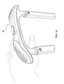
- FIG. 14 shows a right view of the handle of FIG. 1 but with a human hand engaging with the handle.
- FIG. 15 shows the view of the human hand from FIG. 14 with a hashed-oval representing the area of contact between the handle and the palm.
- FIG. 16 shows the handle from the view of FIG. 3 with a human hand grasping the handle and pushing the handle in a first direction.
- FIG. 17 shows the handle from the view of FIG. 16 with a human hand grasping the handle and pushing the handle in a second direction opposite from the direction in FIG. 16 .
- FIG. 18 shows the handle from the view of FIG. 18 with a human hand grasping the handle and depressing an actuator button on the handle.
- FIG. 19 is a front planar view of a first alternative configuration of the handle of FIG. 1 .
- FIG. 20 is a top view of the handle of FIG. 19 .
- FIG. 21 shows the handle of FIG. 19 with a human hand grasping the handle and pushing the handle.
- FIG. 22 shows the handle of FIG. 21 with a human hand grasping the handle and depressing the actuator button on the handle.
- FIG. 23 is a front planar view of a second alternative configuration of the handle of FIG. 1 .
- FIG. 24 is a top view of the handle of FIG. 23 .
- FIG. 25 shows the top view of the handle of FIG. 24 including angles of possible rotation.
- FIG. 26 shows the handle of FIG. 25 with a human hand grasping the handle.
- FIG. 27 is a front planar view of a third alternative configuration of the handle of FIG. 1 .
- FIG. 28 is a top view of the handle of FIG. 27 .
- FIG. 29 shows the top view of the handle of FIG. 24 including angles of possible rotation.
- FIG. 30 is a front sectional view of the third alternative configuration showing the mechanical workings of the actuator.
- FIG. 31 shows the handle of FIG. 27 with a human hand grasping the handle.
- FIG. 32 shows an alternative grasping of the handle shown in FIG. 31 .
- FIG. 33 is a front planar view of a fourth alternative configuration of the handle of FIG. 1 .
- FIG. 34 shows the top view of the handle of FIG. 33 .
- FIG. 35 shows the handle of FIG. 33 with a human hand grasping the handle.
- FIG. 36 shows the handle of FIG. 33 including angles of possible rotation.
- any usage of terms that suggest an absolute orientation e.g. “top”, “bottom”, “front”, “back”, etc.
- orientation shown in a particular figure e.g. “top”, “bottom”, “front”, “back”, etc.
- any usage of terms that suggest an absolute orientation e.g. “top”, “bottom”, “front”, “back”, etc.
- top, bottom, “front”, “back”, etc. are for illustrative convenience and refer to the orientation shown in a particular figure.
- such terms are not to be construed in a limiting sense as it is contemplated that various components may in practice be utilized in orientations that are the same as, or different than those, described or shown.
- luggage 50 comprises a compartment 54 for storing and transporting personal effects or other articles.
- Luggage 50 also comprises a plurality of wheels plurality of wheels 58 - 1 , 58 - 2 , 58 - 3 and 58 - 4 .
- wheels 58 are mounted to compartment 54 , and can be used to roll luggage 50 along a substantially smooth surface.
- Luggage 50 also comprises a handle 62 that connects to compartment 54 via a pair of retractable rods 66 .
- rods 66 are in a fully extended position so that handle 62 is brought within an arm's reach while a person is standing substantially upright.
- rods 66 are movable between the extended position in FIG. 1 and FIG. 2 to a retracted position within a recessed chamber 70 disposed within a side of compartment 54 that is opposite from the side of compartment 54 to which wheels 58 are mounted.
- compartment 54 which can be opened to receive or remove articles, and can be closed for storage or transportation.
- compartment 54 can be of a hard material (e.g. plastic or metal) or a soft material (e.g. fabric).
- Compartment 54 can also have different configurations, including a split configuration comprising two equal size halves or non-equal size halves.
- Compartment 54 can be a backpack, dufflebag, or briefcase.
- Compartment 54 can also be configured to open from one or more different sides, and the means by which it is opened is not particularly limited.
- the configuration, orientation and type of hinging mechanism are not particularly limited. A variety of other types of compartments will now occur to those skilled in the art.
- each wheel can rotate along a rotational axis 74 that is substantially parallel to a rolling surface so that luggage 50 can be rolled in direction “A” in reaction to a force applied along direction “B” to handle 62 .
- Wheels 58 are also configured to spin along an axis 78 that is perpendicular to the rolling surface, to thereby change the orientation of rotational axis 74 so that luggage 50 can be rolled in any direction along rolling surface.
- luggage 50 is shown as being moved in direction “C” (opposite to direction “A” in FIG.
- wheels 58 in reaction to force applied along direction “D” to the opposite side of handle 62 , such that wheels 58 rotate along rotational axis 75 .
- wheels 58 rotate along rotational axis 75 .
- the number and nature of wheels 58 is also not particularly limited. For example, fewer or more wheels can be provided. In other configurations, one or more of the wheels may be configured to spin, or not, along axis 78 .
- Handle 62 thus comprises a body 82 .
- Body 82 has a first end 100 - 1 opposite to a second end 100 - 2 and a proximal edge 104 - 1 and opposite to a distal edge 104 - 2 .
- edges 104 define a length L of body 82 between each end 100 .
- Proximal edge 104 - 1 includes a pair of rod-junctions 86 .
- each rod-junction 86 is implemented as a strut received within a hollow end of a distal end of a respective rod 66 and mechanically fastened thereto by a screw 90 .
- Other configurations for attaching body 82 to rods 66 are contemplated.
- Distal edge 104 - 2 includes a pair of palm grips 108 .
- First palm grip 108 - 1 is situated at first end 100 - 1
- second palm grip 108 - 2 is situated at second end 100 - 2 .
- a central grip 112 is disposed between each palm-grip 108 . While palms grips 108 and central grip 112 are labeled in various Figures, FIG. 8 uses hashed-boxes to more specifically illustrate which portions of body 82 correspond to palms grips 108 and central grip 112 . From the view in FIG. 5 , it can be seen that palm grips 108 are substantially convex while central grip 112 is substantially concave.
- Each palm grip 108 has a shape that complements the palm (or metacarpus) of a human hand, in order to distribute a force across a corresponding area of the palm. In a present embodiment, each palm grip 108 is rounded to further distribute force across the palm. Each palm grip 108 is also substantially tear-drop shaped having wider bulbous portion proximal to its respective end 100 and a narrow bulbous portion proximal central grip 112 . While body 82 is made from a substantially non-deformable material, such as a hard plastic, each palm grip 108 is made from a resiliently-deformable material, such as a foamed plastic, which is affixed to body 82 via a glue or other fastening means. The deformable nature of each palm grip 108 further improves the distribution of force across the area of the palm (or other entity that applies the force) that comes into contact with the palm grip 108 .
- each palm grip 108 is dimpled to increase the level of friction between the palm and the surface of the palm grip 108 , and reduce the likelihood of the palm slipping from the palm grip 108 while luggage 50 is being pushed.
- Other texture patterns, other than dimpling, are contemplated.
- each palm grip 108 is also angled.
- an angle w is shown in relation to palm grip 108 - 2 .
- Angle w defines an obtuse angle measured from a plane parallel to the length L of body 82 .
- the actual length L is not particularly limited, and can be selected to accommodate various sizes of hands according to the teachings herein.
- Angle w is chosen to complement a position for pushing luggage 50 that is well within a natural range of motion of the human wrist, so that the palm of the human hand can engage with a palm grip 108 without requiring an uncomfortable or otherwise unnatural bend in the human wrist.
- Angle w is thus greater than about ninety degrees but less than one-hundred-and-eighty-degrees.
- Angle w is presently preferred to be between about one-hundred-fifty-degrees and about one-hundred-and-ten-degrees. More specifically, angle w is presently preferred to be between about one-hundred-forty-five degrees and about one-hundred-and-twenty-degrees.
- angle w is presently preferred to be between about one-hundred-forty-degrees and about one-hundred-and-thirty-degrees. More specifically, angle w is presently preferred to be about one-hundred-and-thirty-five-degrees.
- central grip 112 is slightly convex along its outer edges, being slightly wider at its outer edges where central grip 112 joins with each palm grip 108 . It should be understood, however, that central grip 112 can have different shapes, including having substantially the same width along its entire length. As viewed in FIG. 5 , central grip is slightly concave along distal edge 104 - 2 . An actuator 116 is disposed in the middle of central grip 112 . Actuator 116 is biased towards a distal position which locks rods 66 in the extended position shown in FIG. 1 and FIG. 2 .
- Actuator 116 may be depressed towards a position that is substantially contiguous with the surface of central grip 112 , which unlocks rods 66 so that rods may be moved between the extended position and the retracted position shown in FIG. 3 .
- Mechanical means are typically provided so that, upon release, actuator 116 is urged to the distal position and locks rods 66 in the retracted position shown in FIG. 3 .
- Further mechanical means may also be provided so that handle 62 can be positioned, and locked, at one or more intermediate positions between the extended position shown in FIG. 1 and FIG. 2 . It is presently preferred to provide at least one such intermediate position, to be discussed further below.
- FIG. 13 , FIG. 14 and FIG. 15 shows the use of palm grips 108 in greater detail.
- FIG. 13 and FIG. 14 show example contact between the palm and a given palm grip 108 .
- FIG. 15 shows an example of the area of contact by palm grip 108 on the palm.
- the palm of a hand can contact substantially the entire surface of a palm grip 108 .
- the wrist can be angled comfortably while still contacting the surface of palm grip 108 and for pushing luggage 50 .
- FIG. 16 and FIG. 17 show example use of central grip 112 .
- the example in FIG. 16 and FIG. 17 contemplate the positioning of rods 66 at an intermediate position, lower than the extended position shown in FIG. 1 and FIG. 2 , but higher than the retracted position.
- FIG. 16 and FIG. 17 demonstrate that central grip 112 may be comfortably grasped.
- FIG. 16 illustrates that palm grip 108 - 1 additionally provides a comfortable thumb rest and palm grip 108 - 2 providing padding for a portion of the palm.
- a force in the direction of arrow B′ can be applied while walking to roll luggage 50 .
- the direction in FIG. 16 is roughly analogous to the direction of movement shown in FIG. 1 .
- a force in the direction of arrow D′ can be applied while walking to roll luggage 50 .
- the direction in FIG. 17 is roughly analogous to the direction of movement shown in FIG. 2 .
- FIG. 18 shows further example use of central grip 112 , whereby central grip is squeezed to accomplish depression of actuator 116 to unlock rods 66 and facilitate their movement between the extended position or the retracted position. While not shown, the grasping of handle 62 in FIG. 18 can also be used to apply a lifting or pulling force on handle 62 .
- FIG. 19 , FIG. 20 , FIG. 21 , and FIG. 22 show a first alternative handle 62 a , which is a variation on handle 62 .
- Handle 62 a has slightly different shape but includes palm grips 108 , while omitting the concavity of central grip 112 .
- FIG. 23 , FIG. 24 , FIG. 25 and FIG. 26 show a second alternative handle 62 b .
- Handle 62 b also omits the concavity of central grip 112 and is rotatable, as shown in FIG. 25 , by ninety degrees to provide a different grasping angle for the wrist.
- FIG. 27 , FIG. 28 , FIG. 29 , FIG. 30 , FIG. 31 and FIG. 32 show a third alternative handle 62 c .
- handle 62 c is also rotatable, as shown in FIG. 29 , by ninety degrees, and to a full one-hundred-and-eighty-degrees to provide a different grasping angles for the wrist.
- FIG. 33 , FIG. 34 , FIG. 35 and FIG. 36 shows a fourth alternative handle 62 d .
- Handle 62 d is pivotable about an axis that is perpendicular to rods 66 to thereby provide different ergonomic angles for grasping.
- handle 62 may be implemented so as to have a partially spheroidal shape (i.e. akin to a section of a sphere) so that handle 62 can be pushed ergonomically from any direction.
Abstract
Description
Claims (39)
Priority Applications (2)
| Application Number | Priority Date | Filing Date | Title |
|---|---|---|---|
| US14/484,669 US9706825B2 (en) | 2010-10-29 | 2014-09-12 | Handle for luggage |
| US14/734,314 US9351554B2 (en) | 2010-10-29 | 2015-06-09 | Handle for luggage |
Applications Claiming Priority (4)
| Application Number | Priority Date | Filing Date | Title |
|---|---|---|---|
| US40797110P | 2010-10-29 | 2010-10-29 | |
| PCT/US2011/057207 WO2012058103A1 (en) | 2010-10-29 | 2011-10-21 | Handle for luggage |
| US13/871,488 US8851251B2 (en) | 2010-10-29 | 2013-04-26 | Handle for luggage |
| US14/484,669 US9706825B2 (en) | 2010-10-29 | 2014-09-12 | Handle for luggage |
Related Parent Applications (1)
| Application Number | Title | Priority Date | Filing Date |
|---|---|---|---|
| US13/871,488 Continuation US8851251B2 (en) | 2010-10-29 | 2013-04-26 | Handle for luggage |
Related Child Applications (1)
| Application Number | Title | Priority Date | Filing Date |
|---|---|---|---|
| US14/734,314 Continuation US9351554B2 (en) | 2010-10-29 | 2015-06-09 | Handle for luggage |
Publications (2)
| Publication Number | Publication Date |
|---|---|
| US20140374206A1 US20140374206A1 (en) | 2014-12-25 |
| US9706825B2 true US9706825B2 (en) | 2017-07-18 |
Family
ID=45381769
Family Applications (3)
| Application Number | Title | Priority Date | Filing Date |
|---|---|---|---|
| US13/871,488 Active US8851251B2 (en) | 2010-10-29 | 2013-04-26 | Handle for luggage |
| US14/484,669 Active US9706825B2 (en) | 2010-10-29 | 2014-09-12 | Handle for luggage |
| US14/734,314 Active US9351554B2 (en) | 2010-10-29 | 2015-06-09 | Handle for luggage |
Family Applications Before (1)
| Application Number | Title | Priority Date | Filing Date |
|---|---|---|---|
| US13/871,488 Active US8851251B2 (en) | 2010-10-29 | 2013-04-26 | Handle for luggage |
Family Applications After (1)
| Application Number | Title | Priority Date | Filing Date |
|---|---|---|---|
| US14/734,314 Active US9351554B2 (en) | 2010-10-29 | 2015-06-09 | Handle for luggage |
Country Status (6)
| Country | Link |
|---|---|
| US (3) | US8851251B2 (en) |
| CN (1) | CN202095728U (en) |
| CA (1) | CA2821168C (en) |
| DE (1) | DE212011100148U1 (en) |
| GB (1) | GB2498504B (en) |
| WO (1) | WO2012058103A1 (en) |
Families Citing this family (18)
| Publication number | Priority date | Publication date | Assignee | Title |
|---|---|---|---|---|
| CN202095728U (en) | 2010-10-29 | 2012-01-04 | 假日集团控股有限公司 | Luggage case handle |
| USD732908S1 (en) * | 2011-03-04 | 2015-06-30 | Jennifer Cucci | Roller board housing |
| JP5907201B2 (en) * | 2014-03-25 | 2016-04-26 | エース株式会社 | Carry handle for bags with wheels |
| US9723902B2 (en) | 2015-02-14 | 2017-08-08 | Boban Jose | Collapsible suitcase, and a method for its use |
| US9918536B2 (en) | 2015-02-14 | 2018-03-20 | Boban Jose | Luggage extension handle having a ring-shaped grip |
| US9918535B2 (en) | 2015-02-14 | 2018-03-20 | Boban Jose | Luggage extension handle having a pocket |
| US20160353882A1 (en) * | 2015-02-14 | 2016-12-08 | Boban Jose | Fold-out tray for use with an item of luggage |
| USD773819S1 (en) | 2015-05-27 | 2016-12-13 | Travelpro Products, Inc. | Handle for luggage |
| US9845915B2 (en) | 2015-09-02 | 2017-12-19 | Boban Jose | Collapsible stand attached to a baggage item and a method for its use |
| US9999283B2 (en) | 2015-12-31 | 2018-06-19 | Boban Jose | Collapsible luggage and a method for its use |
| US9833047B1 (en) | 2016-06-01 | 2017-12-05 | Boban Jose | Locking slider assembly and a method for its manufacture |
| US10085526B2 (en) | 2016-06-01 | 2018-10-02 | Boban Jose | Locking slider assembly and a method for its manufacture |
| US9743721B1 (en) | 2016-06-01 | 2017-08-29 | Boban Jose | Locking slider assembly and a method for its manufacture |
| US9767673B1 (en) | 2016-06-07 | 2017-09-19 | Paul Clip | System and method for detecting that an open bag is being carried |
| FR3072253A1 (en) * | 2017-10-17 | 2019-04-19 | Delsey | ROLLING BAG WITH ERGONOMIC HANDLE |
| JP2019107086A (en) * | 2017-12-15 | 2019-07-04 | ミズノ テクニクス株式会社 | Carry Bag |
| US10595606B1 (en) * | 2019-03-11 | 2020-03-24 | Joy Tong | Dual-button handle grip for retractable luggage handle |
| USD1013384S1 (en) | 2020-08-24 | 2024-02-06 | Ricardo Beverly Hills | Handle on an article of luggage |
Citations (72)
| Publication number | Priority date | Publication date | Assignee | Title |
|---|---|---|---|---|
| US3522955A (en) | 1969-01-16 | 1970-08-04 | Hideaway Handles Inc | Extendable handle assembly |
| US3813729A (en) | 1973-01-04 | 1974-06-04 | M Szabo | Rigid substantially u-shaped handle with closed-cell foam handgrip |
| US4118048A (en) | 1977-04-08 | 1978-10-03 | Seiko Time Corporation | Wheeled sample case |
| US4561526A (en) | 1983-01-03 | 1985-12-31 | Samsonite Corporation | Steering and support handle for wheeled luggage |
| DE3636064A1 (en) | 1986-10-23 | 1988-04-28 | Heinrich Schaefer | Suitcase |
| US4989511A (en) | 1989-05-26 | 1991-02-05 | Flexible Products Company | Handle for a squeegee |
| US5377795A (en) | 1994-05-06 | 1995-01-03 | Vt International Ltd. | Two-way towable luggage |
| US5400494A (en) | 1993-03-01 | 1995-03-28 | Stilley; Russell L. | Method of manufacturing a wheeled garment bag |
| US5452778A (en) | 1994-01-11 | 1995-09-26 | Wang; Jing-Sheng | Retractable luggage carrying handle positioning device |
| US5630250A (en) | 1996-04-09 | 1997-05-20 | Chou; Cheng-Tsan | Drawbar device |
| US5669103A (en) | 1996-06-26 | 1997-09-23 | Clipper Products | Integrated handle for telescoping tubes |
| GB2318973A (en) | 1996-11-08 | 1998-05-13 | Swany Corp | Wheeled bag with extendable handle |
| US5762168A (en) | 1995-10-12 | 1998-06-09 | Swany Corporation | Suitcase having casters |
| US5782325A (en) | 1996-12-24 | 1998-07-21 | Andiamo, Inc. | Extendable-handle rolling suitcase |
| US5890570A (en) | 1995-03-02 | 1999-04-06 | Ourigger, Inc. | Wheeled carry-on case |
| US5914425A (en) | 1997-01-20 | 1999-06-22 | Asta Medica Aktiengesellschaft | Modifications of 2-amino-4-(4-5fluorobenzylamino)-1-ethoxycarbonylaminobenzene, and processes for their preparation |
| US5934425A (en) | 1997-02-13 | 1999-08-10 | Outrigger, Inc. | Swing out handle for wheeled luggage |
| CN2340253Y (en) | 1998-07-29 | 1999-09-29 | 郁成实业有限公司 | Telescopic bars for suitcase |
| US5964451A (en) | 1995-12-28 | 1999-10-12 | Sudheimer; Louis C. | Weed removal tool with ergonomic pressure handle grip |
| US5992588A (en) | 1996-01-19 | 1999-11-30 | Rimowa Kofferfabrik Gmbh | Wheeled suitcase |
| US6065574A (en) | 1997-01-07 | 2000-05-23 | Swany Corporation | Bag mounted with casters |
| US6193033B1 (en) | 1997-06-09 | 2001-02-27 | Outrigger, Inc. | Towable carrying case |
| CN2440362Y (en) | 2000-07-07 | 2001-08-01 | 陈首卯 | Improved pulling rod of suitcase |
| US6301746B1 (en) | 1998-01-09 | 2001-10-16 | Andiamo, Inc. | Telescoping handle assembly for luggage and other luggable items |
| US20020014382A1 (en) | 2000-08-01 | 2002-02-07 | Chaw Khong Technology Co., Ltd. | Combination carrying handle and retractable handle |
| US20020024189A1 (en) | 2000-08-30 | 2002-02-28 | Pen-I Chen | Swivel wheel mounting arrangement for travel bag |
| US6434790B1 (en) | 2000-08-07 | 2002-08-20 | Shou-Mao Chen | Pull rod of luggage |
| US6450308B1 (en) | 2000-09-16 | 2002-09-17 | Chaw Khong Technology Co., Ltd. | Safety mechanism for bezel of luggage with retractable handle |
| US6484362B1 (en) | 1999-02-17 | 2002-11-26 | Chaw Khong Technology Co. Ltd. | Retractable handle assembly with multiple engaging position for wheeled luggage |
| US6533086B1 (en) | 1995-11-22 | 2003-03-18 | Samsonite Corporation | Ergonomic upright wheeled luggage |
| US20030079950A1 (en) | 2001-10-26 | 2003-05-01 | Chaw Khong Technolgoy Co., Ltd. | Handle assembly having a single handle rod of wheeled luggage |
| US6564426B1 (en) | 2002-02-21 | 2003-05-20 | Gin Chiao Wang | Retractable handle assembly having rotatable hand grip |
| US20030102195A1 (en) | 2000-11-02 | 2003-06-05 | Mittleman David D. | Pivotal handle for towable baggage |
| US20030132080A1 (en) | 2000-04-11 | 2003-07-17 | Dababneh Awwad J. | Ergonomically designed wheeled luggage |
| WO2003063637A2 (en) | 2002-01-25 | 2003-08-07 | Samsonite Corporation | Wide handle upright luggage case |
| US6920666B1 (en) | 2003-11-12 | 2005-07-26 | Shou Mao Chen | Control mechanism of a pull rod |
| US20050173876A1 (en) | 2001-11-02 | 2005-08-11 | Sadow Bernard D. | Angular handle assembly for wheeled luggage |
| DE102005002898A1 (en) | 2004-01-26 | 2005-10-13 | Rudolf Kuschel | Suitcase on wheels, comprising three or more specifically arranged wheels for more convenient use |
| US20050258621A1 (en) | 2004-05-18 | 2005-11-24 | Chris Johnson | Portable luggage carts/carriers |
| US20050279123A1 (en) | 2004-06-17 | 2005-12-22 | John Maldonado | Hardside cooler with soft cover |
| US20050279600A1 (en) | 2004-02-18 | 2005-12-22 | Goldwitz Brian L | Suitcase handle |
| US20060006037A1 (en) | 2004-07-08 | 2006-01-12 | Frank Hsieh | Retractable handle device for bag |
| US20060027985A1 (en) | 2004-08-04 | 2006-02-09 | Etsuo Miyoshi | Bag with caster wheels |
| US20060031994A1 (en) | 2004-06-22 | 2006-02-16 | Willat Boyd I | Conformable pod for a manual implement |
| CN2825016Y (en) | 2005-08-18 | 2006-10-11 | 高鹏实业有限公司 | A case handle |
| US20060272126A1 (en) | 2005-06-01 | 2006-12-07 | Burgess Andrew A | Spinning handle grip assembly for towable luggage item |
| US7188715B1 (en) | 2004-01-28 | 2007-03-13 | Shou Mao Chen | Pull handle provided with a grip handle with an adjustable angle |
| CN2894387Y (en) | 2006-01-27 | 2007-05-02 | 乔工科技股份有限公司 | Trunk single-bar handle rotating structure |
| US20070158159A1 (en) | 2005-06-15 | 2007-07-12 | Burgess Andrew A | Thermally insulated handle systems for wheeled items towable by a person |
| USD553364S1 (en) | 2006-10-17 | 2007-10-23 | Jerry Moon | Luggage handle |
| US20070266527A1 (en) | 2006-05-18 | 2007-11-22 | Chien-Hung Chen | Semi-flexible handle |
| US20080083592A1 (en) | 2006-09-08 | 2008-04-10 | Joy Mangano | Versatile and reconfigurable luggage |
| US20080179153A1 (en) | 2007-01-29 | 2008-07-31 | Chen-Chuan Wu | Grip assembly for luggage |
| WO2008098116A1 (en) | 2007-02-07 | 2008-08-14 | Samsonite Corporation | System for cinching a resilient luggage case |
| USD575511S1 (en) | 2007-04-23 | 2008-08-26 | Jerry Moon | Luggage handle |
| US7438308B2 (en) | 2004-01-14 | 2008-10-21 | Jansport Apparel Corp. | Ergonomic telescoping handle assembly for wheeled luggage |
| US7461730B2 (en) | 2001-09-05 | 2008-12-09 | Inventive Travelware | Handle apparatus with cantilevered handle grip for luggage case |
| US20080308370A1 (en) | 2007-06-14 | 2008-12-18 | Kyong-Soo Chung | Push-pull wheeled luggage with swingable rear wheels and at least one fixed front wheel |
| WO2009029244A1 (en) | 2007-08-24 | 2009-03-05 | The Ene Group, Llc | Luggage system |
| USD591511S1 (en) | 2008-05-02 | 2009-05-05 | Hersun Plastic Co., Ltd. | Luggage grip |
| US20090218187A1 (en) | 2007-02-08 | 2009-09-03 | Kyong-Soo Chung | Tilted Push-Pull Wheeled Luggage with a Removable Front Swingable Wheel with an Elongated Neck for the Removable Front Swingable Wheel |
| CN201451800U (en) | 2009-07-06 | 2010-05-12 | 杭州杰玛箱包有限公司 | Anti-collapse and foldable travel suitcase with universal wheels |
| US20100293755A1 (en) | 2009-05-19 | 2010-11-25 | Steven Steele Draper | Omni-directional handle |
| US20110079479A1 (en) | 2009-10-07 | 2011-04-07 | Sheng Cho Yang | Enhanced structure for base with roller and belt of hardshell zipper case |
| US20110088987A1 (en) | 2009-10-20 | 2011-04-21 | Samsonite Ip Holdings S.A.R.L | Luggage panel with integrated carry handle for soft-side type luggage cases |
| USD637398S1 (en) | 2010-03-16 | 2011-05-10 | Hanhui Jiang | Pull-rod handle for luggage |
| US20110168507A1 (en) | 2010-01-14 | 2011-07-14 | James Keith Penley | Steerable Carriage Apparatus |
| USD648132S1 (en) | 2010-11-05 | 2011-11-08 | Chen-Chuan Wu | Luggage grip |
| USD651803S1 (en) | 2010-11-05 | 2012-01-10 | Chen-Chuan Wu | Handle for luggage |
| USD696019S1 (en) | 2011-10-21 | 2013-12-24 | Travelpro International Inc. | Handle for luggage |
| USD712152S1 (en) | 2014-01-28 | 2014-09-02 | Joy Tong | Luggage handle pull bar |
| US8851251B2 (en) | 2010-10-29 | 2014-10-07 | Travelpro International, Inc. | Handle for luggage |
Family Cites Families (1)
| Publication number | Priority date | Publication date | Assignee | Title |
|---|---|---|---|---|
| US7660029B2 (en) * | 2006-08-01 | 2010-02-09 | Universite De Moncton | Chromogenically tunable photonic crystals |
-
2011
- 2011-03-02 CN CN201120052399XU patent/CN202095728U/en not_active Expired - Lifetime
- 2011-10-21 CA CA2821168A patent/CA2821168C/en active Active
- 2011-10-21 GB GB1309378.6A patent/GB2498504B/en active Active
- 2011-10-21 WO PCT/US2011/057207 patent/WO2012058103A1/en active Application Filing
- 2011-10-21 DE DE212011100148U patent/DE212011100148U1/en not_active Expired - Lifetime
-
2013
- 2013-04-26 US US13/871,488 patent/US8851251B2/en active Active
-
2014
- 2014-09-12 US US14/484,669 patent/US9706825B2/en active Active
-
2015
- 2015-06-09 US US14/734,314 patent/US9351554B2/en active Active
Patent Citations (76)
| Publication number | Priority date | Publication date | Assignee | Title |
|---|---|---|---|---|
| US3522955A (en) | 1969-01-16 | 1970-08-04 | Hideaway Handles Inc | Extendable handle assembly |
| US3813729A (en) | 1973-01-04 | 1974-06-04 | M Szabo | Rigid substantially u-shaped handle with closed-cell foam handgrip |
| US4118048A (en) | 1977-04-08 | 1978-10-03 | Seiko Time Corporation | Wheeled sample case |
| US4561526A (en) | 1983-01-03 | 1985-12-31 | Samsonite Corporation | Steering and support handle for wheeled luggage |
| DE3636064A1 (en) | 1986-10-23 | 1988-04-28 | Heinrich Schaefer | Suitcase |
| US4989511A (en) | 1989-05-26 | 1991-02-05 | Flexible Products Company | Handle for a squeegee |
| US5400494A (en) | 1993-03-01 | 1995-03-28 | Stilley; Russell L. | Method of manufacturing a wheeled garment bag |
| US5452778A (en) | 1994-01-11 | 1995-09-26 | Wang; Jing-Sheng | Retractable luggage carrying handle positioning device |
| US5377795A (en) | 1994-05-06 | 1995-01-03 | Vt International Ltd. | Two-way towable luggage |
| US5890570A (en) | 1995-03-02 | 1999-04-06 | Ourigger, Inc. | Wheeled carry-on case |
| US5762168A (en) | 1995-10-12 | 1998-06-09 | Swany Corporation | Suitcase having casters |
| US6533086B1 (en) | 1995-11-22 | 2003-03-18 | Samsonite Corporation | Ergonomic upright wheeled luggage |
| US5964451A (en) | 1995-12-28 | 1999-10-12 | Sudheimer; Louis C. | Weed removal tool with ergonomic pressure handle grip |
| US5992588A (en) | 1996-01-19 | 1999-11-30 | Rimowa Kofferfabrik Gmbh | Wheeled suitcase |
| US5630250A (en) | 1996-04-09 | 1997-05-20 | Chou; Cheng-Tsan | Drawbar device |
| US5669103A (en) | 1996-06-26 | 1997-09-23 | Clipper Products | Integrated handle for telescoping tubes |
| GB2318973A (en) | 1996-11-08 | 1998-05-13 | Swany Corp | Wheeled bag with extendable handle |
| US5782325A (en) | 1996-12-24 | 1998-07-21 | Andiamo, Inc. | Extendable-handle rolling suitcase |
| US6065574A (en) | 1997-01-07 | 2000-05-23 | Swany Corporation | Bag mounted with casters |
| US5914425A (en) | 1997-01-20 | 1999-06-22 | Asta Medica Aktiengesellschaft | Modifications of 2-amino-4-(4-5fluorobenzylamino)-1-ethoxycarbonylaminobenzene, and processes for their preparation |
| US5934425A (en) | 1997-02-13 | 1999-08-10 | Outrigger, Inc. | Swing out handle for wheeled luggage |
| US6193033B1 (en) | 1997-06-09 | 2001-02-27 | Outrigger, Inc. | Towable carrying case |
| US6301746B1 (en) | 1998-01-09 | 2001-10-16 | Andiamo, Inc. | Telescoping handle assembly for luggage and other luggable items |
| CN2340253Y (en) | 1998-07-29 | 1999-09-29 | 郁成实业有限公司 | Telescopic bars for suitcase |
| US6484362B1 (en) | 1999-02-17 | 2002-11-26 | Chaw Khong Technology Co. Ltd. | Retractable handle assembly with multiple engaging position for wheeled luggage |
| US20030132080A1 (en) | 2000-04-11 | 2003-07-17 | Dababneh Awwad J. | Ergonomically designed wheeled luggage |
| CN2440362Y (en) | 2000-07-07 | 2001-08-01 | 陈首卯 | Improved pulling rod of suitcase |
| US20020014382A1 (en) | 2000-08-01 | 2002-02-07 | Chaw Khong Technology Co., Ltd. | Combination carrying handle and retractable handle |
| US6434790B1 (en) | 2000-08-07 | 2002-08-20 | Shou-Mao Chen | Pull rod of luggage |
| US20020024189A1 (en) | 2000-08-30 | 2002-02-28 | Pen-I Chen | Swivel wheel mounting arrangement for travel bag |
| US6450308B1 (en) | 2000-09-16 | 2002-09-17 | Chaw Khong Technology Co., Ltd. | Safety mechanism for bezel of luggage with retractable handle |
| US20030102195A1 (en) | 2000-11-02 | 2003-06-05 | Mittleman David D. | Pivotal handle for towable baggage |
| US7461730B2 (en) | 2001-09-05 | 2008-12-09 | Inventive Travelware | Handle apparatus with cantilevered handle grip for luggage case |
| US20030079950A1 (en) | 2001-10-26 | 2003-05-01 | Chaw Khong Technolgoy Co., Ltd. | Handle assembly having a single handle rod of wheeled luggage |
| US20050173876A1 (en) | 2001-11-02 | 2005-08-11 | Sadow Bernard D. | Angular handle assembly for wheeled luggage |
| WO2003063637A2 (en) | 2002-01-25 | 2003-08-07 | Samsonite Corporation | Wide handle upright luggage case |
| CN1622773A (en) | 2002-01-25 | 2005-06-01 | 新秀丽公司 | Wide handle upright luggage case |
| US6564426B1 (en) | 2002-02-21 | 2003-05-20 | Gin Chiao Wang | Retractable handle assembly having rotatable hand grip |
| US6920666B1 (en) | 2003-11-12 | 2005-07-26 | Shou Mao Chen | Control mechanism of a pull rod |
| US7438308B2 (en) | 2004-01-14 | 2008-10-21 | Jansport Apparel Corp. | Ergonomic telescoping handle assembly for wheeled luggage |
| DE102005002898A1 (en) | 2004-01-26 | 2005-10-13 | Rudolf Kuschel | Suitcase on wheels, comprising three or more specifically arranged wheels for more convenient use |
| US7188715B1 (en) | 2004-01-28 | 2007-03-13 | Shou Mao Chen | Pull handle provided with a grip handle with an adjustable angle |
| US20050279600A1 (en) | 2004-02-18 | 2005-12-22 | Goldwitz Brian L | Suitcase handle |
| US20050258621A1 (en) | 2004-05-18 | 2005-11-24 | Chris Johnson | Portable luggage carts/carriers |
| US20050279123A1 (en) | 2004-06-17 | 2005-12-22 | John Maldonado | Hardside cooler with soft cover |
| US20060031994A1 (en) | 2004-06-22 | 2006-02-16 | Willat Boyd I | Conformable pod for a manual implement |
| US20060006037A1 (en) | 2004-07-08 | 2006-01-12 | Frank Hsieh | Retractable handle device for bag |
| US20060027985A1 (en) | 2004-08-04 | 2006-02-09 | Etsuo Miyoshi | Bag with caster wheels |
| US20060272126A1 (en) | 2005-06-01 | 2006-12-07 | Burgess Andrew A | Spinning handle grip assembly for towable luggage item |
| US20070158159A1 (en) | 2005-06-15 | 2007-07-12 | Burgess Andrew A | Thermally insulated handle systems for wheeled items towable by a person |
| CN2825016Y (en) | 2005-08-18 | 2006-10-11 | 高鹏实业有限公司 | A case handle |
| CN2894387Y (en) | 2006-01-27 | 2007-05-02 | 乔工科技股份有限公司 | Trunk single-bar handle rotating structure |
| US20070266527A1 (en) | 2006-05-18 | 2007-11-22 | Chien-Hung Chen | Semi-flexible handle |
| US20080083592A1 (en) | 2006-09-08 | 2008-04-10 | Joy Mangano | Versatile and reconfigurable luggage |
| USD553364S1 (en) | 2006-10-17 | 2007-10-23 | Jerry Moon | Luggage handle |
| US20080179153A1 (en) | 2007-01-29 | 2008-07-31 | Chen-Chuan Wu | Grip assembly for luggage |
| US7467696B2 (en) | 2007-01-29 | 2008-12-23 | Hersun Plastic Co., Ltd. | Grip assembly for luggage |
| WO2008098116A1 (en) | 2007-02-07 | 2008-08-14 | Samsonite Corporation | System for cinching a resilient luggage case |
| US20090218187A1 (en) | 2007-02-08 | 2009-09-03 | Kyong-Soo Chung | Tilted Push-Pull Wheeled Luggage with a Removable Front Swingable Wheel with an Elongated Neck for the Removable Front Swingable Wheel |
| USD575511S1 (en) | 2007-04-23 | 2008-08-26 | Jerry Moon | Luggage handle |
| US20080308370A1 (en) | 2007-06-14 | 2008-12-18 | Kyong-Soo Chung | Push-pull wheeled luggage with swingable rear wheels and at least one fixed front wheel |
| US20090139814A1 (en) | 2007-08-24 | 2009-06-04 | Robert Grossman | Luggage system |
| WO2009029244A1 (en) | 2007-08-24 | 2009-03-05 | The Ene Group, Llc | Luggage system |
| USD591511S1 (en) | 2008-05-02 | 2009-05-05 | Hersun Plastic Co., Ltd. | Luggage grip |
| US20100293755A1 (en) | 2009-05-19 | 2010-11-25 | Steven Steele Draper | Omni-directional handle |
| CN201451800U (en) | 2009-07-06 | 2010-05-12 | 杭州杰玛箱包有限公司 | Anti-collapse and foldable travel suitcase with universal wheels |
| US20110079479A1 (en) | 2009-10-07 | 2011-04-07 | Sheng Cho Yang | Enhanced structure for base with roller and belt of hardshell zipper case |
| US20110088987A1 (en) | 2009-10-20 | 2011-04-21 | Samsonite Ip Holdings S.A.R.L | Luggage panel with integrated carry handle for soft-side type luggage cases |
| US20110168507A1 (en) | 2010-01-14 | 2011-07-14 | James Keith Penley | Steerable Carriage Apparatus |
| USD637398S1 (en) | 2010-03-16 | 2011-05-10 | Hanhui Jiang | Pull-rod handle for luggage |
| US8851251B2 (en) | 2010-10-29 | 2014-10-07 | Travelpro International, Inc. | Handle for luggage |
| US9351554B2 (en) * | 2010-10-29 | 2016-05-31 | Travelpro International, Inc. | Handle for luggage |
| USD648132S1 (en) | 2010-11-05 | 2011-11-08 | Chen-Chuan Wu | Luggage grip |
| USD651803S1 (en) | 2010-11-05 | 2012-01-10 | Chen-Chuan Wu | Handle for luggage |
| USD696019S1 (en) | 2011-10-21 | 2013-12-24 | Travelpro International Inc. | Handle for luggage |
| USD712152S1 (en) | 2014-01-28 | 2014-09-02 | Joy Tong | Luggage handle pull bar |
Non-Patent Citations (10)
| Title |
|---|
| Comfort Grip Luggage Handle Extender, http://www.flightattendantshop.com/product/detail,cfm/nid/6/pid/267, Oct. 14, 2010, 1 page. |
| Defendant's Answer, Defenses, Affirmative Defenses and Counterclaims to Plaintiff's Complaint for Patent Infringement, United States District Court, Southern District of Florida, Case No. 15-80340-CIV-Middlebrooks/Brannon, Travelpro International, Inc. (Plaintiff) vs. Ricardo Beverly Hills, Inc. (Defendant) vs. Ricardo Beverly Hills, Inc. (Counter-Plaintiff) vs. Travelpro International, Inc. (Counter-Defendant), 8 pages. |
| Email dated Thursday, Jul. 9, 2015, 11:46 AM, Subject: TravelPro v. Ricardo Rule 408 Correspondence, (individual names/email addresses redacted), 1 page. |
| Evaluation Report of Utility Model Patent, State Intellectual Property Office of the People's Republic of China, Mailing Date-May 30, 2013, 7 pages. |
| Evaluation Report of Utility Model Patent, State Intellectual Property Office of the People's Republic of China, Mailing Date—May 30, 2013, 7 pages. |
| Great Britain Examination Report, Application No. GB1309378.6, Applicant: Travelpro International Inc., Date of Report: Apr. 9, 2015, 5 pages. |
| Thumb Pad on a Cup, http://www.promotional-gifts-inc.com/custom-wholesale/Drinkware-Mugs/Spnuzzo-150z-Plastic-Mug-with-Steel-Interior-Handle-6253.htm, Oct. 14, 2010, 1 page. |
| United Kingdom Examination Report under Section 18(3), Application No. GB1309378.6, Applicant: Travelpro International Inc., Report Date: Aug. 10, 2015, 4 pages. |
| United Kingdom Examination Report Under Section 18(3), Application No. GB1309378.6, dated Nov. 6, 2015, Applicant: Travelpro International, Inc., 4 pages. |
| Werks Traveler 20* Deluxe Wheeled Travel Bag, http://www.wellpromo.com/upload/upimg60/Werks-Traveler-20-Deluxe Whee-151660.jpg, Oct. 14, 2010, 1 page. |
Also Published As
| Publication number | Publication date |
|---|---|
| US20140374206A1 (en) | 2014-12-25 |
| CA2821168A1 (en) | 2012-05-03 |
| US20150272291A1 (en) | 2015-10-01 |
| GB201309378D0 (en) | 2013-07-10 |
| DE212011100148U1 (en) | 2013-05-21 |
| US8851251B2 (en) | 2014-10-07 |
| GB2498504A (en) | 2013-07-17 |
| GB2498504B (en) | 2016-07-13 |
| WO2012058103A1 (en) | 2012-05-03 |
| CN202095728U (en) | 2012-01-04 |
| US20130233662A1 (en) | 2013-09-12 |
| US9351554B2 (en) | 2016-05-31 |
| CA2821168C (en) | 2018-05-01 |
Similar Documents
| Publication | Publication Date | Title |
|---|---|---|
| US9706825B2 (en) | Handle for luggage | |
| US7458488B2 (en) | Portable carrying device with retractable strap | |
| US5464080A (en) | Universally pivotal luggage steering apparatus | |
| US7665782B2 (en) | Pick up device with locking mechanism and leverage action trigger | |
| US20030132080A1 (en) | Ergonomically designed wheeled luggage | |
| US6874604B2 (en) | Adjustable luggage handle system with locking pin | |
| US20090301833A1 (en) | Side handle luggage | |
| TWM280837U (en) | Handle-grasping wrap | |
| US7270223B2 (en) | Luggage handle system with pivot grip | |
| US9744425B2 (en) | Travel cover with a swivel handle | |
| US20020116790A1 (en) | Handle conversion device | |
| US20070158159A1 (en) | Thermally insulated handle systems for wheeled items towable by a person | |
| AU2013100462A4 (en) | Handle for luggage | |
| US20150223591A1 (en) | Fatigue reduction device | |
| US7874602B2 (en) | Carrying apparatus | |
| US20050087415A1 (en) | Rotatable handle for towable luggage | |
| GB2433426A (en) | Wheeled luggage with supplementary support device | |
| US20130228037A1 (en) | Ergonomic handgrip for a moveable apparatus | |
| WO2001078548A2 (en) | Ergonomically designed wheeled luggage | |
| US20090183756A1 (en) | Ambulatory assistance device with storage | |
| JP2008067796A (en) | Grip | |
| JP3002601U (en) | Luggage holding grip | |
| TWM537422U (en) | Handle made by combining heterogeneous materials | |
| KR20070000060U (en) | A traveling bag handle | |
| JP2010255154A (en) | Protector for carrying baggage |
Legal Events
| Date | Code | Title | Description |
|---|---|---|---|
| AS | Assignment |
Owner name: IDEAZ, LLC, CONNECTICUT Free format text: ASSIGNMENT OF ASSIGNORS INTEREST;ASSIGNORS:SENER, JAMES T.;HAGEMAN, CHRISTOPHER D.;MATHIEU, DAVID L.;AND OTHERS;SIGNING DATES FROM 20101203 TO 20101207;REEL/FRAME:033729/0965 |
|
| AS | Assignment |
Owner name: TRAVELPRO INTERNATIONAL INC., FLORIDA Free format text: ASSIGNMENT OF ASSIGNORS INTEREST;ASSIGNOR:IDEAZ, LLC;REEL/FRAME:033736/0259 Effective date: 20101203 |
|
| AS | Assignment |
Owner name: TRIANGLE CAPITAL CORPORATION, AS ADMINISTRATIVE AG Free format text: SECURITY INTEREST;ASSIGNOR:TRAVELPRO PRODUCTS, INC.;REEL/FRAME:038748/0241 Effective date: 20160520 |
|
| AS | Assignment |
Owner name: TRIANGLE CAPITAL CORPORATION, AS ADMINISTRATIVE AG Free format text: CORRECTIVE ASSIGNMENT TO CORRECT THE PROPERTY NUMBER: 13453238; PATENT NUMBER: 9256419 PREVIOUSLY RECORDED AT REEL: 038748 FRAME: 0241. ASSIGNOR(S) HEREBY CONFIRMS THE SECURITY INTEREST;ASSIGNOR:TRAVELPRO PRODUCTS, INC.;REEL/FRAME:038890/0717 Effective date: 20160520 Owner name: ANTARES CAPITAL LP, AS ADMINISTRATIVE AGENT, ILLIN Free format text: SECURITY INTEREST;ASSIGNOR:TRAVELPRO PRODUCTS, INC.;REEL/FRAME:038794/0252 Effective date: 20160520 |
|
| AS | Assignment |
Owner name: TRAVELPRO PRODUCTS, INC., FLORIDA Free format text: ASSIGNMENT OF ASSIGNORS INTEREST;ASSIGNOR:TRAVELPRO INTERNATIONAL, INC.;REEL/FRAME:038936/0480 Effective date: 20160520 |
|
| STCF | Information on status: patent grant |
Free format text: PATENTED CASE |
|
| MAFP | Maintenance fee payment |
Free format text: PAYMENT OF MAINTENANCE FEE, 4TH YR, SMALL ENTITY (ORIGINAL EVENT CODE: M2551); ENTITY STATUS OF PATENT OWNER: SMALL ENTITY Year of fee payment: 4 |
|
| AS | Assignment |
Owner name: BSP AGENCY, LLC, AS THE SUCCESSOR AGENT, NEW YORK Free format text: NOTICE OF SUCCESSOR AGENT AND ASSIGNMENT OF SECURITY INTEREST (INTELLECTUAL PROPERTY);ASSIGNOR:TRIANGLE CAPITAL CORPORATION, AS THE RETIRING AGENT;REEL/FRAME:055617/0837 Effective date: 20180731 |
|
| AS | Assignment |
Owner name: TRAVELPRO PRODUCTS, INC., NEW YORK Free format text: TERMINATION AND RELEASE OF SECURITY INTEREST IN PATENTS;ASSIGNOR:BSP AGENCY, LLC (SUCCESSOR AGENT TO TRIANGLE CAPITAL CORPORATION);REEL/FRAME:065335/0812 Effective date: 20231024 |
|
| AS | Assignment |
Owner name: ACQUIOM AGENCY SERVICES LLC, COLORADO Free format text: SECURITY INTEREST;ASSIGNORS:TRAVELPRO BSI, INC.;TRAVELPRO PRODUCTS, INC.;REEL/FRAME:065335/0656 Effective date: 20231024 Owner name: TRAVELPRO PRODUCTS, INC., NEW YORK Free format text: RELEASE BY SECURED PARTY;ASSIGNOR:ANTARES CAPITAL LP, AS ADMINISTRATIVE AGENT AND COLLATERAL AGENT;REEL/FRAME:065333/0144 Effective date: 20231024 |
|
| AS | Assignment |
Owner name: PNC BANK, NATIONAL ASSOCIATION, AS AGENT, NEW YORK Free format text: SECURITY AGREEMENT;ASSIGNORS:TRAVELPRO BSI, INC.;TRAVELPRO PRODUCTS, INC.;REEL/FRAME:065395/0328 Effective date: 20231024 |