US9708945B2 - Electric heating assisted passive and active regeneration for efficient emission controls of diesel engines - Google Patents
Electric heating assisted passive and active regeneration for efficient emission controls of diesel engines Download PDFInfo
- Publication number
- US9708945B2 US9708945B2 US14/800,338 US201514800338A US9708945B2 US 9708945 B2 US9708945 B2 US 9708945B2 US 201514800338 A US201514800338 A US 201514800338A US 9708945 B2 US9708945 B2 US 9708945B2
- Authority
- US
- United States
- Prior art keywords
- exhaust
- electric heater
- heating
- dpf
- exhaust gas
- Prior art date
- Legal status (The legal status is an assumption and is not a legal conclusion. Google has not performed a legal analysis and makes no representation as to the accuracy of the status listed.)
- Active, expires
Links
Images


Classifications
-
- F—MECHANICAL ENGINEERING; LIGHTING; HEATING; WEAPONS; BLASTING
- F01—MACHINES OR ENGINES IN GENERAL; ENGINE PLANTS IN GENERAL; STEAM ENGINES
- F01N—GAS-FLOW SILENCERS OR EXHAUST APPARATUS FOR MACHINES OR ENGINES IN GENERAL; GAS-FLOW SILENCERS OR EXHAUST APPARATUS FOR INTERNAL COMBUSTION ENGINES
- F01N3/00—Exhaust or silencing apparatus having means for purifying, rendering innocuous, or otherwise treating exhaust
- F01N3/02—Exhaust or silencing apparatus having means for purifying, rendering innocuous, or otherwise treating exhaust for cooling, or for removing solid constituents of, exhaust
- F01N3/021—Exhaust or silencing apparatus having means for purifying, rendering innocuous, or otherwise treating exhaust for cooling, or for removing solid constituents of, exhaust by means of filters
- F01N3/033—Exhaust or silencing apparatus having means for purifying, rendering innocuous, or otherwise treating exhaust for cooling, or for removing solid constituents of, exhaust by means of filters in combination with other devices
- F01N3/035—Exhaust or silencing apparatus having means for purifying, rendering innocuous, or otherwise treating exhaust for cooling, or for removing solid constituents of, exhaust by means of filters in combination with other devices with catalytic reactors, e.g. catalysed diesel particulate filters
-
- F—MECHANICAL ENGINEERING; LIGHTING; HEATING; WEAPONS; BLASTING
- F01—MACHINES OR ENGINES IN GENERAL; ENGINE PLANTS IN GENERAL; STEAM ENGINES
- F01N—GAS-FLOW SILENCERS OR EXHAUST APPARATUS FOR MACHINES OR ENGINES IN GENERAL; GAS-FLOW SILENCERS OR EXHAUST APPARATUS FOR INTERNAL COMBUSTION ENGINES
- F01N13/00—Exhaust or silencing apparatus characterised by constructional features ; Exhaust or silencing apparatus, or parts thereof, having pertinent characteristics not provided for in, or of interest apart from, groups F01N1/00 - F01N5/00, F01N9/00, F01N11/00
- F01N13/009—Exhaust or silencing apparatus characterised by constructional features ; Exhaust or silencing apparatus, or parts thereof, having pertinent characteristics not provided for in, or of interest apart from, groups F01N1/00 - F01N5/00, F01N9/00, F01N11/00 having two or more separate purifying devices arranged in series
-
- F—MECHANICAL ENGINEERING; LIGHTING; HEATING; WEAPONS; BLASTING
- F01—MACHINES OR ENGINES IN GENERAL; ENGINE PLANTS IN GENERAL; STEAM ENGINES
- F01N—GAS-FLOW SILENCERS OR EXHAUST APPARATUS FOR MACHINES OR ENGINES IN GENERAL; GAS-FLOW SILENCERS OR EXHAUST APPARATUS FOR INTERNAL COMBUSTION ENGINES
- F01N3/00—Exhaust or silencing apparatus having means for purifying, rendering innocuous, or otherwise treating exhaust
- F01N3/02—Exhaust or silencing apparatus having means for purifying, rendering innocuous, or otherwise treating exhaust for cooling, or for removing solid constituents of, exhaust
- F01N3/021—Exhaust or silencing apparatus having means for purifying, rendering innocuous, or otherwise treating exhaust for cooling, or for removing solid constituents of, exhaust by means of filters
- F01N3/023—Exhaust or silencing apparatus having means for purifying, rendering innocuous, or otherwise treating exhaust for cooling, or for removing solid constituents of, exhaust by means of filters using means for regenerating the filters, e.g. by burning trapped particles
- F01N3/027—Exhaust or silencing apparatus having means for purifying, rendering innocuous, or otherwise treating exhaust for cooling, or for removing solid constituents of, exhaust by means of filters using means for regenerating the filters, e.g. by burning trapped particles using electric or magnetic heating means
-
- F—MECHANICAL ENGINEERING; LIGHTING; HEATING; WEAPONS; BLASTING
- F01—MACHINES OR ENGINES IN GENERAL; ENGINE PLANTS IN GENERAL; STEAM ENGINES
- F01N—GAS-FLOW SILENCERS OR EXHAUST APPARATUS FOR MACHINES OR ENGINES IN GENERAL; GAS-FLOW SILENCERS OR EXHAUST APPARATUS FOR INTERNAL COMBUSTION ENGINES
- F01N3/00—Exhaust or silencing apparatus having means for purifying, rendering innocuous, or otherwise treating exhaust
- F01N3/08—Exhaust or silencing apparatus having means for purifying, rendering innocuous, or otherwise treating exhaust for rendering innocuous
- F01N3/10—Exhaust or silencing apparatus having means for purifying, rendering innocuous, or otherwise treating exhaust for rendering innocuous by thermal or catalytic conversion of noxious components of exhaust
- F01N3/18—Exhaust or silencing apparatus having means for purifying, rendering innocuous, or otherwise treating exhaust for rendering innocuous by thermal or catalytic conversion of noxious components of exhaust characterised by methods of operation; Control
- F01N3/20—Exhaust or silencing apparatus having means for purifying, rendering innocuous, or otherwise treating exhaust for rendering innocuous by thermal or catalytic conversion of noxious components of exhaust characterised by methods of operation; Control specially adapted for catalytic conversion ; Methods of operation or control of catalytic converters
- F01N3/2006—Periodically heating or cooling catalytic reactors, e.g. at cold starting or overheating
- F01N3/2013—Periodically heating or cooling catalytic reactors, e.g. at cold starting or overheating using electric or magnetic heating means
-
- F—MECHANICAL ENGINEERING; LIGHTING; HEATING; WEAPONS; BLASTING
- F01—MACHINES OR ENGINES IN GENERAL; ENGINE PLANTS IN GENERAL; STEAM ENGINES
- F01N—GAS-FLOW SILENCERS OR EXHAUST APPARATUS FOR MACHINES OR ENGINES IN GENERAL; GAS-FLOW SILENCERS OR EXHAUST APPARATUS FOR INTERNAL COMBUSTION ENGINES
- F01N9/00—Electrical control of exhaust gas treating apparatus
- F01N9/002—Electrical control of exhaust gas treating apparatus of filter regeneration, e.g. detection of clogging
-
- F—MECHANICAL ENGINEERING; LIGHTING; HEATING; WEAPONS; BLASTING
- F01—MACHINES OR ENGINES IN GENERAL; ENGINE PLANTS IN GENERAL; STEAM ENGINES
- F01N—GAS-FLOW SILENCERS OR EXHAUST APPARATUS FOR MACHINES OR ENGINES IN GENERAL; GAS-FLOW SILENCERS OR EXHAUST APPARATUS FOR INTERNAL COMBUSTION ENGINES
- F01N2240/00—Combination or association of two or more different exhaust treating devices, or of at least one such device with an auxiliary device, not covered by indexing codes F01N2230/00 or F01N2250/00, one of the devices being
- F01N2240/16—Combination or association of two or more different exhaust treating devices, or of at least one such device with an auxiliary device, not covered by indexing codes F01N2230/00 or F01N2250/00, one of the devices being an electric heater, i.e. a resistance heater
-
- F—MECHANICAL ENGINEERING; LIGHTING; HEATING; WEAPONS; BLASTING
- F01—MACHINES OR ENGINES IN GENERAL; ENGINE PLANTS IN GENERAL; STEAM ENGINES
- F01N—GAS-FLOW SILENCERS OR EXHAUST APPARATUS FOR MACHINES OR ENGINES IN GENERAL; GAS-FLOW SILENCERS OR EXHAUST APPARATUS FOR INTERNAL COMBUSTION ENGINES
- F01N2590/00—Exhaust or silencing apparatus adapted to particular use, e.g. for military applications, airplanes, submarines
- F01N2590/08—Exhaust or silencing apparatus adapted to particular use, e.g. for military applications, airplanes, submarines for heavy duty applications, e.g. trucks, buses, tractors, locomotives
-
- F—MECHANICAL ENGINEERING; LIGHTING; HEATING; WEAPONS; BLASTING
- F01—MACHINES OR ENGINES IN GENERAL; ENGINE PLANTS IN GENERAL; STEAM ENGINES
- F01N—GAS-FLOW SILENCERS OR EXHAUST APPARATUS FOR MACHINES OR ENGINES IN GENERAL; GAS-FLOW SILENCERS OR EXHAUST APPARATUS FOR INTERNAL COMBUSTION ENGINES
- F01N2900/00—Details of electrical control or of the monitoring of the exhaust gas treating apparatus
- F01N2900/06—Parameters used for exhaust control or diagnosing
- F01N2900/14—Parameters used for exhaust control or diagnosing said parameters being related to the exhaust gas
- F01N2900/1404—Exhaust gas temperature
-
- Y—GENERAL TAGGING OF NEW TECHNOLOGICAL DEVELOPMENTS; GENERAL TAGGING OF CROSS-SECTIONAL TECHNOLOGIES SPANNING OVER SEVERAL SECTIONS OF THE IPC; TECHNICAL SUBJECTS COVERED BY FORMER USPC CROSS-REFERENCE ART COLLECTIONS [XRACs] AND DIGESTS
- Y02—TECHNOLOGIES OR APPLICATIONS FOR MITIGATION OR ADAPTATION AGAINST CLIMATE CHANGE
- Y02T—CLIMATE CHANGE MITIGATION TECHNOLOGIES RELATED TO TRANSPORTATION
- Y02T10/00—Road transport of goods or passengers
- Y02T10/10—Internal combustion engine [ICE] based vehicles
- Y02T10/12—Improving ICE efficiencies
-
- Y02T10/26—
-
- Y—GENERAL TAGGING OF NEW TECHNOLOGICAL DEVELOPMENTS; GENERAL TAGGING OF CROSS-SECTIONAL TECHNOLOGIES SPANNING OVER SEVERAL SECTIONS OF THE IPC; TECHNICAL SUBJECTS COVERED BY FORMER USPC CROSS-REFERENCE ART COLLECTIONS [XRACs] AND DIGESTS
- Y02—TECHNOLOGIES OR APPLICATIONS FOR MITIGATION OR ADAPTATION AGAINST CLIMATE CHANGE
- Y02T—CLIMATE CHANGE MITIGATION TECHNOLOGIES RELATED TO TRANSPORTATION
- Y02T10/00—Road transport of goods or passengers
- Y02T10/10—Internal combustion engine [ICE] based vehicles
- Y02T10/40—Engine management systems
-
- Y02T10/47—
Definitions
- the present disclosure relates to exhaust aftertreatment systems for diesel engines, and more particularly to electric heating and control to provide assisted heating in the exhaust aftertreatment systems.
- Diesel engines have been used in a variety of applications such as locomotives, marines and engine-generators.
- exhaust aftertreatment systems have been employed and generally include a Diesel Oxidation Catalyst (DOC), a Diesel Particulate Filter (DPF), and an SCR (Selective Catalytic Reduction of NOx) to treat the exhaust gas and to control emissions to atmosphere or the outside environment.
- DOC Diesel Oxidation Catalyst
- DPF Diesel Particulate Filter
- SCR Selective Catalytic Reduction of NOx
- One method of increasing the exhaust gas temperature is through injecting hydrocarbon upstream from a DOC either in the exhaust pipe or inside the cylinder during the exhaust stroke. This method increases fuel consumption and also changes composition of the exhaust gas. For example, when fuel injection is injected in the exhaust, NO 2 generation in the DOC is significantly reduced. NO 2 is an effective reagent for passive regeneration of DPF at much lower temperature range. Therefore, the reduced NO 2 generation adversely affects the passive regeneration of the DPF.
- a method of heating an exhaust gas in an exhaust aftertreatment system includes an electric heater, a Diesel Oxidation Catalyst (DOC) and a diesel particulate filter (DPF).
- the method comprises heating an exhaust gas to a predetermined temperature when the DPF is not actively regenerated, and heating the exhaust gas to reduce an exhaust temperature gradient across the exhaust conduit.
- DOC Diesel Oxidation Catalyst
- DPF diesel particulate filter
- a method of heating an exhaust gas in an exhaust aftertreatment system includes an electric heater, a Diesel Oxidation Catalyst (DOC) and a diesel particulate filter (DPF).
- the method comprises selecting a heating mode between a plurality of heating modes based on engine load and status of the DPF.
- the method further comprises heating the exhaust gas by operating the electric heater in the selected heating mode, and operating the electric heater in a passive regeneration heating mode to heat an exhaust gas to a predetermined temperature to increase NO2 generation when the DPF is not actively regenerated and the engine load is less than or equal to approximately 25%.
- a method of heating an exhaust gas in an exhaust after treatment system comprises selecting a heating mode between a plurality of heating modes based on an engine load and a status of a component of the exhaust aftertreatment system. The method further comprises heating the exhaust gas by operating the electric heater in the selected heating mode, and operating the electric heater in a passive regeneration heating mode to heat an exhaust gas to a predetermined temperature to increase NO2 generation when an engine load is less than or equal to approximately 25%.
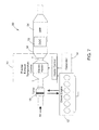
- FIG. 1 is a schematic view of an engine system including a heating module constructed in accordance with the teachings of the present disclosure
- FIG. 2 is a schematic view of a heating module constructed in accordance with the teachings of the present disclosure
- FIG. 3 is a graph showing relationship between concentration of NO 2 and catalyst temperature
- FIG. 4 is a schematic view of an electric heater
- FIG. 5 is a graph showing a heating strategy for operating the electric heater
- FIG. 6 is a table showing the properties of the exhaust gas at different engine loads.
- FIG. 7 is a schematic view of another form of an engine system including a heating module constructed in accordance with the teachings of the present disclosure.
- an engine system 10 generally includes a diesel engine 12 , a generator 14 , a turbocharger 16 , and an exhaust aftertreatment system 18 .
- the exhaust aftertreatment system 18 is disposed downstream from a turbocharger 16 for treating exhaust gases from the diesel engine 12 before the exhaust gases are released to atmosphere.
- the exhaust aftertreatment system 18 includes a heating module 20 , a DOC 22 , DPF 24 , and an SCR 26 .
- the heating module 20 includes an electric heater 28 disposed upstream from the DOC 22 , and a heater control module 30 for controlling operation of the electric heater 28 .
- the exhaust aftertreatment system 18 includes an upstream exhaust conduit 32 that receives the electric heater 28 therein, an intermediate exhaust conduit 34 in which the DOC 22 and DPF 24 are received, and a downstream exhaust conduit 36 in which the SCR is disposed.
- the DOC 22 is disposed downstream from the electric heater 28 and serves as a catalyst to oxide carbon monoxide and any unburnt hydrocarbons in the exhaust gas. In addition, The DOC 22 converts harmful nitric oxide (NO) into nitrogen dioxide (NO 2 ).
- the DPF 24 is disposed downstream from the DOC 22 to remove diesel particulate matter (PM) or soot from the exhaust gas.
- the SCR 26 is disposed downstream from the DPF 24 and, with the aid of a catalyst, converts nitrogen oxides (NOx) into nitrogen (N 2 ) and water.
- a urea water solution injector 27 is disposed downstream from the DPF 24 and upstream from the SCR 26 for injecting urea water solution into the stream of the exhaust gas.
- the electric heater 28 provides assisted heating of the exhaust gas flowing in the exhaust conduits 32 , 34 , 36 .
- the generator 14 is connected to the diesel engine 12 to drive the diesel engine 12 during engine startup as an option and to supply electricity to the electric heater 34 during normal engine operation.
- the heater control module 30 strategically controls the electric heater 28 in different heating modes to facilitate both active and passive regeneration of the DPF 24 .
- Regeneration is the process of burning and removing the accumulated particulates matters from the DPF 24 .
- Regeneration can occur passively or actively. Passive regeneration can occur in normal engine operation when the temperature of the exhaust gas is sufficiently high. Active regeneration can occur based on a monitored DPF condition or based on a predetermined timing schedule by introducing very high heat to the exhaust aftertreatment system 10 . Active regeneration can be achieved by proper engine control management to increase the exhaust temperature through late fuel injection or injection during the expansion stroke. Active regeneration can also be achieved through assisted heating by an electric heater. Active regeneration requires much more heat than passive regeneration and thus subjects the ceramic structure of the DPF 24 to the risk of cracking and decreases catalytic coating life time.
- the heater control module 30 strategically controls operation of the electric heater 28 based on an engine load and a status of the DPF 24 to provide assisted heating in both active and passive regeneration of the DPF.
- the heater control module 24 may be a part of an engine control unit (ECU) (not shown) or external to the ECU.
- the ECU controls operation of the diesel engine 12 , a fuel injection system (not shown), among others, and acquires and stores various parameters relating to engine operating conditions, including but not limited to, exhaust temperature, diesel engine load, flow conditions (air flow and air pressure etc.)
- the heater control module 30 receives inputs from the ECU to make the proper determination how to operate the electric heater 28 .
- the control module could also receive information from stand alone after treatment control systems.
- the heater control module 30 includes a heating mode determination module 62 and a heater operating module 63 including a passive regeneration heating module 64 and an active regeneration heating module 66 .
- the electric heater 22 can be operated in two operating modes: passive regeneration heating mode and active regeneration heating mode.
- the heating mode determination module 62 determines a desired heating mode based on an engine load and the status of the DPF 24 . When the DPF 24 is actively regenerated, the desired heating mode is the active regeneration heating mode. When the DPF 24 is not actively regenerated and the engine load is low, for example, at 10%, the desired heating mode is the passive regeneration heating mode.
- the heating mode determination module 62 may include a heating strategy that specifies the correlation among the heating modes, duration, engine loads and the desired exhaust temperature rise. The heating mode determination module 62 also determines when the electric heater 28 should be turned on or off during normal engine operation. In response to the determination of the heating mode determination module 62 , the heater operating module 63 operates the electric heater 28 accordingly.
- the electric heater 28 is controlled to heat the exhaust gas to a predetermined temperature which allows for optimum NO 2 generation in the DOC 22 .
- NO 2 is an effective reactant for passive regeneration of DPF 24 .
- Increasing NO 2 generation can facilitate passive regeneration of DPF 24 .
- the electric heater 28 is controlled to heat the exhaust gas differently to reduce exhaust temperature gradient across the exhaust conduits. When the temperature gradient is reduced, the active regeneration can be accomplished more efficiently.
- the passive regeneration heating module 64 When the heating mode determination module 62 determines that the passive heating mode is desired, the passive regeneration heating module 64 then controls the electric heater 28 to heat the exhaust gas to a predetermined temperature.
- the passive regeneration heating module 64 calculates and determines the desired temperature rise based on an exhaust temperature and the predetermined temperature.
- the exhaust temperature may be obtained from the input from the ECU, temperature sensors.
- the predetermined temperature depends on the properties of the catalysts in the DOC 14 and is set to allow for optimum NO 2 generation.
- the NO 2 concentration at the outlet of the DOC 14 is dependent on the temperature of the exhaust gas.
- the NO 2 concentration is relatively high when the catalyst temperature is in the range of 300 to 460° C., particularly in the range from 320 to 380° C. Therefore, the predetermined temperature is set to be in the range of 300 to 460° C., and preferably in the range from 320 to 380° C.
- the electric heater 28 heats exhaust gas to the predetermined temperature, an optimum amount of NO 2 is generated to facilitate passive regeneration of the DPF 24 .
- the particulate matter is accumulated on the DPF at a lower rate, thereby reducing the frequency for active regeneration. As a result, the likelihood of DPF ceramic cracking and degradation of the catalysts due to high heat associated with active regeneration (generally in the range of 500 to 650° C.) are reduced.
- the desired heating mode is the active regeneration heating mode.
- the active regeneration heating module 66 controls the electric heater 28 to provide differential heating to the exhaust gas.
- the electrical heater 22 generates more heat along the periphery of the electric heater and less heat at the center of the exhaust conduit.
- the exhaust conduit generally has a relatively higher temperature along the central axis of the conduit and a relatively lower temperature proximate the conduit wall.
- the exhaust gas proximate the exhaust conduit wall also needs to be heated to the desired active regeneration temperature. Due to the temperature gradient across the cross section of the exhaust conduit, the exhaust gas proximate the center of the exhaust conduit is unnecessarily overheated, subjecting the center portion of the DPF 24 to higher heat and higher risk of cracks.
- By operating the electric heater 28 to reduce the temperature gradient less heat is required to heat the exhaust gas to the desired active regeneration temperature. Therefore, the likelihood of overheating at the center of the DPF and the accompanying problems is reduced.
- an exemplary embodiment of the electric heater 28 is shown to have a low watt density zone 40 proximate the center and a high watt density zone 42 along the periphery of the electric heater 28 .
- the electric heater 28 can provide differential heating across the exhaust conduit.
- the electric heater 28 is powered by the generator 14 .
- the generator 14 drives the diesel engine 30 during engine startup. After the diesel engine 30 starts to operate on its own, the generator 14 is driven by the diesel engine 14 to generate electricity to power other electronics or electrical devices.
- the heating strategy allows for use of available electricity generating capacity when it is not needed to power the other electrical and electronic systems during low engine load operation.
- the heating mode determination module 62 includes a heating strategy which specifies the correlations among the heating modes, the exhaust temperature rise, the engine loads. As shown in the exemplary diagram, when the engine load is low and the DPF backpressure is in the range of medium to high, the target exhaust temperature rise (delta) would be low and the electric heater 28 is operated in the passive regeneration mode. For example, the electric heater 22 is in the passive regeneration heating mode when the diesel engine 12 is operating near low load conditions such as 10% load. The electric heater 22 demands less electric power from the generator 14 because the desired temperature rise (delta) is less than that for active regeneration and because less exhaust gas is generated from the diesel engine 30 due to the low engine load.
- the electric heater 28 is turned off. Active regeneration of DPF may be initiated when the engine load is low or according to a predetermined schedule to benefit from heating lower exhaust mass flow.
- the electric heater is turned on and operated in the active regeneration heating mode to provide differential heating.
- the active regeneration is completed and the engine load starts to increase, the electric heater 28 is turned off.
- the table illustrates the exhaust contents for different load conditions.
- the exhaust gas exhibits the lowest exhaust flow (1925 cfm) and the highest available specific NOx (6.8 g/bhp-hr) among the 5 load conditions for a gen-set type of large diesel engine.
- the DOC downstream of the heater will generate maximum amount of NO 2 due to higher available NOx under this load engine condition.
- NO 2 passively oxidizes the particulate matter loaded DPF downstream of the DOC at its maximum rate.
- the delta T rise is only 85° C. which will minimize energy consumption in comparison with an active regeneration which will have a delta T as high as 350° C.
- notch 1 condition on a GE locomotive engine with a flow of 54.8 kg/min it will require 73 KW energy input to heat the exhaust and have a temperature rise (delta) of 76° C. up to 355° C. It will need 315 KW to heat the exhaust up to 607° C. at the same notch 1 condition.
- the electric heating strategy of the present disclosure may replace the fuel-injection-based active regeneration.
- the heating module 20 of the present disclosure applies to all diesel engines which can generate electricity while in operation, preferably to those non-EGR diesel engines having high engine-out NOx at lower duty cycles. As shown, the heating module 20 can be applied to a catalyzed DPF only exhaust system, as well as an exhaust aftertreatment system 50 that includes DOC 52 and DPF 54 without SCR.
- the heating module 20 of the present disclosure has at least the following benefits:
- the present disclosure may include methods of heating portions of the gas flow in a more indirect matter.
- the system could sense cooler portions within the gas flow cross section and provide heat where needed to provide a more even temperature distribution and compensate for heat losses.
- the system may regenerate in certain sections or zones at different times.
- These alternate forms of the present disclosure would also have a corresponding heater type that supports zone heating across the cross-section of gas flow, such as, by way of example, layered heaters or modular heat trace heaters such as those disclosed in pending U.S. application Ser. No. 11/238,747 titled “Modular Layered Heater System” and in U.S. Pat. No. 7,626,146 titled “Modular Heater Systems,” both of which are commonly assigned with the present application and the contents of which are incorporated by reference herein in their entirety.
Abstract
Description
4NO+2(NH2)2CO+O2→4N2+4H2O+2CO2
Claims (13)
Priority Applications (3)
| Application Number | Priority Date | Filing Date | Title |
|---|---|---|---|
| US14/800,338 US9708945B2 (en) | 2012-02-22 | 2015-07-15 | Electric heating assisted passive and active regeneration for efficient emission controls of diesel engines |
| US15/599,875 US10036292B2 (en) | 2012-02-22 | 2017-05-19 | Electric heating assisted passive and active regeneration for efficient emission controls of diesel engines |
| US16/025,104 US10669907B2 (en) | 2012-02-22 | 2018-07-02 | Electric heating assisted passive and active regeneration for efficient emission controls of diesel engines |
Applications Claiming Priority (3)
| Application Number | Priority Date | Filing Date | Title |
|---|---|---|---|
| US201261601923P | 2012-02-22 | 2012-02-22 | |
| US13/773,176 US9115616B2 (en) | 2012-02-22 | 2013-02-21 | Electric heating assisted passive and active regeneration for efficient emission controls of diesel engines |
| US14/800,338 US9708945B2 (en) | 2012-02-22 | 2015-07-15 | Electric heating assisted passive and active regeneration for efficient emission controls of diesel engines |
Related Parent Applications (1)
| Application Number | Title | Priority Date | Filing Date |
|---|---|---|---|
| US13/773,176 Division US9115616B2 (en) | 2012-02-22 | 2013-02-21 | Electric heating assisted passive and active regeneration for efficient emission controls of diesel engines |
Related Child Applications (1)
| Application Number | Title | Priority Date | Filing Date |
|---|---|---|---|
| US15/599,875 Division US10036292B2 (en) | 2012-02-22 | 2017-05-19 | Electric heating assisted passive and active regeneration for efficient emission controls of diesel engines |
Publications (2)
| Publication Number | Publication Date |
|---|---|
| US20150337703A1 US20150337703A1 (en) | 2015-11-26 |
| US9708945B2 true US9708945B2 (en) | 2017-07-18 |
Family
ID=48050235
Family Applications (4)
| Application Number | Title | Priority Date | Filing Date |
|---|---|---|---|
| US13/773,176 Active 2033-07-27 US9115616B2 (en) | 2012-02-22 | 2013-02-21 | Electric heating assisted passive and active regeneration for efficient emission controls of diesel engines |
| US14/800,338 Active 2033-05-27 US9708945B2 (en) | 2012-02-22 | 2015-07-15 | Electric heating assisted passive and active regeneration for efficient emission controls of diesel engines |
| US15/599,875 Active US10036292B2 (en) | 2012-02-22 | 2017-05-19 | Electric heating assisted passive and active regeneration for efficient emission controls of diesel engines |
| US16/025,104 Active 2033-04-10 US10669907B2 (en) | 2012-02-22 | 2018-07-02 | Electric heating assisted passive and active regeneration for efficient emission controls of diesel engines |
Family Applications Before (1)
| Application Number | Title | Priority Date | Filing Date |
|---|---|---|---|
| US13/773,176 Active 2033-07-27 US9115616B2 (en) | 2012-02-22 | 2013-02-21 | Electric heating assisted passive and active regeneration for efficient emission controls of diesel engines |
Family Applications After (2)
| Application Number | Title | Priority Date | Filing Date |
|---|---|---|---|
| US15/599,875 Active US10036292B2 (en) | 2012-02-22 | 2017-05-19 | Electric heating assisted passive and active regeneration for efficient emission controls of diesel engines |
| US16/025,104 Active 2033-04-10 US10669907B2 (en) | 2012-02-22 | 2018-07-02 | Electric heating assisted passive and active regeneration for efficient emission controls of diesel engines |
Country Status (6)
| Country | Link |
|---|---|
| US (4) | US9115616B2 (en) |
| EP (2) | EP3192991B1 (en) |
| JP (2) | JP6018646B2 (en) |
| CA (1) | CA2865165C (en) |
| ES (2) | ES2737849T3 (en) |
| WO (1) | WO2013126575A1 (en) |
Cited By (2)
| Publication number | Priority date | Publication date | Assignee | Title |
|---|---|---|---|---|
| US10036292B2 (en) * | 2012-02-22 | 2018-07-31 | Watlow Electric Manufacturing Company | Electric heating assisted passive and active regeneration for efficient emission controls of diesel engines |
| DE102018208980A1 (en) | 2018-06-07 | 2019-12-12 | Ford Global Technologies, Llc | Process for heating a catalyst |
Families Citing this family (30)
| Publication number | Priority date | Publication date | Assignee | Title |
|---|---|---|---|---|
| GB201204419D0 (en) * | 2012-03-13 | 2012-04-25 | Jaguar Cars | Regeneration of diesel particle filter |
| KR101955533B1 (en) * | 2012-10-16 | 2019-03-07 | 주식회사 두산 | Multi-step Regeneration Apparatus of DPF and Regeneration Method for the same |
| EP2989304A1 (en) * | 2013-04-26 | 2016-03-02 | Watlow Electric Manufacturing Company | Smart heating system |
| US10287943B1 (en) * | 2015-12-23 | 2019-05-14 | Clean Power Technologies, LLC | System comprising duel-fuel and after treatment for heavy-heavy duty diesel (HHDD) engines |
| EP3184769B1 (en) * | 2015-12-25 | 2018-07-18 | Kubota Corporation | Exhaust apparatus for diesel engine |
| DE102016224430B4 (en) | 2015-12-29 | 2023-12-14 | Ford Global Technologies, Llc | Method for determining a driving profile for regeneration of an exhaust gas aftertreatment device by means of electric heating for a vehicle with an internal combustion engine and control device for an exhaust gas aftertreatment system and vehicle |
| MX2018010593A (en) | 2016-03-02 | 2019-08-12 | Watlow Electric Mfg | Thermal storage device for use in a fluid flow system. |
| US10161276B2 (en) * | 2016-06-20 | 2018-12-25 | GM Global Technology Operations LLC | Method and system for non-uniform catalyst heating for internal combustion engine |
| DE102016114427A1 (en) * | 2016-08-04 | 2018-02-08 | Volkswagen Aktiengesellschaft | Process for the regeneration of a particulate filter |
| US9975543B1 (en) * | 2017-04-04 | 2018-05-22 | Cummins Emission Solutions Inc. | Systems and methods for waste heat utilization in combustion-electric propulsion systems |
| RU176973U1 (en) * | 2017-04-10 | 2018-02-06 | Федеральное государственное бюджетное образовательное учреждение высшего образования "Южно-Уральский государственный аграрный университет" (ФГБОУ ВО "Южно-Уральский ГАУ") | THERMOELECTRIC MAT |
| DE102017115408A1 (en) | 2017-07-10 | 2019-01-10 | Volkswagen Aktiengesellschaft | Exhaust gas aftertreatment system and method for exhaust aftertreatment of an internal combustion engine |
| DE102017212909A1 (en) * | 2017-07-27 | 2019-01-31 | Robert Bosch Gmbh | Method for controlling and / or regulating the exhaust aftertreatment in a motor vehicle and control device |
| FR3077331B1 (en) * | 2018-02-01 | 2020-01-03 | Psa Automobiles Sa | METHOD FOR CONTROLLING AN ELECTRIC HEATER OF A SELECTIVE CATALYTIC REDUCTION SYSTEM OF A HEAT ENGINE |
| JP2019152138A (en) * | 2018-03-02 | 2019-09-12 | いすゞ自動車株式会社 | Exhaust emission control device of internal combustion engine and vehicle |
| US11440528B2 (en) | 2018-07-27 | 2022-09-13 | Cummins Inc. | Systems and methods for managing aftertreatment systems |
| US10480369B1 (en) | 2018-09-26 | 2019-11-19 | FEV North America Inc. | Exhaust after-treatment system for diesel internal combustion engines |
| GB2579647B (en) * | 2018-12-10 | 2022-12-07 | Bamford Excavators Ltd | Engine system |
| GB2585951B (en) | 2019-07-26 | 2023-02-01 | Bamford Excavators Ltd | System for working machine |
| CN110848010B (en) * | 2019-11-29 | 2020-11-20 | 潍柴动力股份有限公司 | Exhaust temperature control system and control method |
| DE102020100468A1 (en) | 2020-01-10 | 2021-07-15 | Volkswagen Aktiengesellschaft | Exhaust aftertreatment system and method for exhaust aftertreatment of an internal combustion engine |
| CN111365095A (en) * | 2020-03-20 | 2020-07-03 | 一汽解放汽车有限公司 | Electric heating particle catcher post-processing system for diesel engine |
| US11365662B2 (en) * | 2020-03-25 | 2022-06-21 | Cummins Inc. | Systems and methods for coordinated exhaust temperature control with electric heater and engine |
| EP4158174A1 (en) | 2020-05-27 | 2023-04-05 | Cummins, Inc. | Systems and methods for coordination of skip-fire and aftertreatment heater operation to maintain exhaust gas temperature |
| US11339698B2 (en) | 2020-05-27 | 2022-05-24 | Cummins Inc. | Multiple heater exhaust aftertreatment system architecture and methods of control thereof |
| US11428133B2 (en) | 2020-05-27 | 2022-08-30 | Cummins Inc. | Systems and methods for managing catalyst temperature based on location |
| DE102022206430A1 (en) | 2021-06-29 | 2022-12-29 | Cummins Emission Solutions Inc. | Systems and methods for reducing NOx emissions from aftertreatment systems |
| DE102021210761A1 (en) | 2021-09-27 | 2023-03-30 | Vitesco Technologies GmbH | Heating conductor for heating an exhaust gas stream of an internal combustion engine |
| CN113775396B (en) * | 2021-10-15 | 2022-09-16 | 无锡威孚力达催化净化器有限责任公司 | Control method, control device and control system for removing PM in DPF |
| CN113914982A (en) * | 2021-11-01 | 2022-01-11 | 中国重汽集团济南动力有限公司 | System and method for detecting passive regeneration efficiency of particle trap |
Citations (10)
| Publication number | Priority date | Publication date | Assignee | Title |
|---|---|---|---|---|
| JPH0842325A (en) | 1994-07-28 | 1996-02-13 | Nippon Soken Inc | Exhaust fine particle purifying device for internal combustion engine |
| JPH08338229A (en) | 1995-06-15 | 1996-12-24 | Toyota Motor Corp | Exhaust emission control device for diesel engine |
| JPH10131741A (en) | 1996-10-29 | 1998-05-19 | Sumitomo Electric Ind Ltd | Particulate trap for diesel engine |
| JP2003293728A (en) | 2002-04-01 | 2003-10-15 | Mitsubishi Heavy Ind Ltd | Exhaust gas treatment device |
| US20090071338A1 (en) * | 2007-09-14 | 2009-03-19 | Gm Global Technology Operations, Inc. | Overlap zoned electrically heated particulate filter |
| US20090113883A1 (en) * | 2007-10-04 | 2009-05-07 | Gm Global Technology Operations, Inc. | Variable power distribution for zoned regeneration of an electrically heated particulate filter |
| US20100095655A1 (en) * | 2007-08-31 | 2010-04-22 | Gm Global Technology Operations, Inc. | Zoned electrical heater arranged in spaced relationship from particulate filter |
| US20100326403A1 (en) | 2009-06-29 | 2010-12-30 | Gm Global Technology Operations, Inc. | Electrically heated particulate filter regeneration during engine start/stop operation |
| US20110000194A1 (en) | 2009-07-02 | 2011-01-06 | Gm Global Technology Operations, Inc. | Selective catalytic reduction system using electrically heated catalyst |
| US20110030554A1 (en) | 2009-08-05 | 2011-02-10 | Gm Global Technology Operations, Inc. | Electric heater and control system and method for electrically heated particulate filters |
Family Cites Families (23)
| Publication number | Priority date | Publication date | Assignee | Title |
|---|---|---|---|---|
| JP3000762B2 (en) * | 1991-10-31 | 2000-01-17 | 株式会社日本自動車部品総合研究所 | Exhaust particulate cleaning equipment |
| JPH07269328A (en) * | 1994-03-31 | 1995-10-17 | Nissan Motor Co Ltd | Exhaust particulate treatment device for internal combustion engine |
| JPH08296426A (en) * | 1995-04-24 | 1996-11-12 | Nippondenso Co Ltd | Exhaust particulates purifying device |
| JP3899534B2 (en) * | 1995-08-14 | 2007-03-28 | トヨタ自動車株式会社 | Exhaust gas purification method for diesel engine |
| JP3607976B2 (en) * | 1999-03-29 | 2005-01-05 | トヨタ自動車株式会社 | Exhaust gas purification device for internal combustion engine |
| JP3904768B2 (en) * | 1999-09-06 | 2007-04-11 | 日野自動車株式会社 | Diesel engine exhaust gas particulate filter cleaning and regeneration device |
| JP2001280121A (en) * | 2000-03-31 | 2001-10-10 | Isuzu Motors Ltd | Continuous regeneration-type particulate filter device |
| JP3800933B2 (en) * | 2000-08-03 | 2006-07-26 | 日産自動車株式会社 | Exhaust particulate processing device for internal combustion engine |
| DE10131336A1 (en) * | 2001-06-28 | 2003-01-23 | Eberspaecher J Gmbh & Co | Vehicle motor exhaust gas cleaning system has heater for gas flow into particle filter and heat exchanger linked to the motor cooling circuit and vehicle interior heating |
| JP2002266625A (en) * | 2001-12-27 | 2002-09-18 | Toyota Motor Corp | Exhaust emission control device for diesel engine |
| US20050050870A1 (en) * | 2003-03-03 | 2005-03-10 | Cheng Shi-Wai S. | Method and apparatus for filtering exhaust particulates |
| EP1803328B1 (en) * | 2004-09-30 | 2012-04-11 | Watlow Electric Manufacturing Company | Modular layered heater system |
| US7626146B2 (en) | 2005-08-09 | 2009-12-01 | Watlow Electric Manufacturing Company | Modular heater systems |
| US7919733B2 (en) * | 2005-08-09 | 2011-04-05 | Watlow Electric Manufacturing Company | Modular heater systems |
| US20080078170A1 (en) * | 2006-09-29 | 2008-04-03 | Gehrke Christopher R | Managing temperature in an exhaust treatment system |
| US8151558B2 (en) * | 2008-01-31 | 2012-04-10 | Caterpillar Inc. | Exhaust system implementing SCR and EGR |
| JP2011511897A (en) * | 2008-02-07 | 2011-04-14 | マック トラックス インコーポレイテッド | Method and apparatus for regenerating a catalytic diesel particulate filter (DPF) by active NO2 utilization regeneration with enhanced effective NO2 supply |
| CN101981281A (en) * | 2008-04-02 | 2011-02-23 | 马克卡车公司 | System and method for treating diesel exhaust gases |
| ATE476246T1 (en) * | 2008-05-23 | 2010-08-15 | Umicore Ag & Co Kg | DEVICE FOR CLEANING DIESEL EXHAUST GASES |
| US8051644B2 (en) * | 2009-02-18 | 2011-11-08 | GM Global Technology Operations LLC | Electrically heated particulate filter zone-based post fuel injection system |
| JP2010265862A (en) * | 2009-05-18 | 2010-11-25 | Toyota Industries Corp | Exhaust emission control device |
| US8631643B2 (en) * | 2009-12-22 | 2014-01-21 | Perkins Engines Company Limited | Regeneration assist delay period |
| EP3192991B1 (en) * | 2012-02-22 | 2019-04-24 | Watlow Electric Manufacturing Company | Method of heating an exhaust gas in an exhaust aftertreatment system |
-
2013
- 2013-02-21 EP EP17158493.1A patent/EP3192991B1/en active Active
- 2013-02-21 US US13/773,176 patent/US9115616B2/en active Active
- 2013-02-21 WO PCT/US2013/027142 patent/WO2013126575A1/en active Application Filing
- 2013-02-21 EP EP13714727.8A patent/EP2834488B1/en active Active
- 2013-02-21 JP JP2014558824A patent/JP6018646B2/en active Active
- 2013-02-21 ES ES17158493T patent/ES2737849T3/en active Active
- 2013-02-21 CA CA2865165A patent/CA2865165C/en active Active
- 2013-02-21 ES ES13714727.8T patent/ES2638605T3/en active Active
-
2015
- 2015-07-15 US US14/800,338 patent/US9708945B2/en active Active
-
2016
- 2016-09-30 JP JP2016192378A patent/JP6335995B2/en active Active
-
2017
- 2017-05-19 US US15/599,875 patent/US10036292B2/en active Active
-
2018
- 2018-07-02 US US16/025,104 patent/US10669907B2/en active Active
Patent Citations (10)
| Publication number | Priority date | Publication date | Assignee | Title |
|---|---|---|---|---|
| JPH0842325A (en) | 1994-07-28 | 1996-02-13 | Nippon Soken Inc | Exhaust fine particle purifying device for internal combustion engine |
| JPH08338229A (en) | 1995-06-15 | 1996-12-24 | Toyota Motor Corp | Exhaust emission control device for diesel engine |
| JPH10131741A (en) | 1996-10-29 | 1998-05-19 | Sumitomo Electric Ind Ltd | Particulate trap for diesel engine |
| JP2003293728A (en) | 2002-04-01 | 2003-10-15 | Mitsubishi Heavy Ind Ltd | Exhaust gas treatment device |
| US20100095655A1 (en) * | 2007-08-31 | 2010-04-22 | Gm Global Technology Operations, Inc. | Zoned electrical heater arranged in spaced relationship from particulate filter |
| US20090071338A1 (en) * | 2007-09-14 | 2009-03-19 | Gm Global Technology Operations, Inc. | Overlap zoned electrically heated particulate filter |
| US20090113883A1 (en) * | 2007-10-04 | 2009-05-07 | Gm Global Technology Operations, Inc. | Variable power distribution for zoned regeneration of an electrically heated particulate filter |
| US20100326403A1 (en) | 2009-06-29 | 2010-12-30 | Gm Global Technology Operations, Inc. | Electrically heated particulate filter regeneration during engine start/stop operation |
| US20110000194A1 (en) | 2009-07-02 | 2011-01-06 | Gm Global Technology Operations, Inc. | Selective catalytic reduction system using electrically heated catalyst |
| US20110030554A1 (en) | 2009-08-05 | 2011-02-10 | Gm Global Technology Operations, Inc. | Electric heater and control system and method for electrically heated particulate filters |
Non-Patent Citations (3)
| Title |
|---|
| ISRWO of PCT/US2013/027142 dated Jun. 11, 2013. |
| Office Action and English Translation of related Japanese Patent Application No. 2014-558824 dated Mar. 29, 2016. |
| Office Action based on related EP application No. 13714727.8 dated Jun. 14, 2016. |
Cited By (4)
| Publication number | Priority date | Publication date | Assignee | Title |
|---|---|---|---|---|
| US10036292B2 (en) * | 2012-02-22 | 2018-07-31 | Watlow Electric Manufacturing Company | Electric heating assisted passive and active regeneration for efficient emission controls of diesel engines |
| US20180313244A1 (en) * | 2012-02-22 | 2018-11-01 | Watlow Electric Manufacturing Company | Electric heating assisted passive and active regeneration for efficient emission controls of diesel engines |
| US10669907B2 (en) * | 2012-02-22 | 2020-06-02 | Watlow Electric Manufacturing Company | Electric heating assisted passive and active regeneration for efficient emission controls of diesel engines |
| DE102018208980A1 (en) | 2018-06-07 | 2019-12-12 | Ford Global Technologies, Llc | Process for heating a catalyst |
Also Published As
| Publication number | Publication date |
|---|---|
| US10036292B2 (en) | 2018-07-31 |
| JP2017020510A (en) | 2017-01-26 |
| US20130213010A1 (en) | 2013-08-22 |
| US20170254239A1 (en) | 2017-09-07 |
| US20180313244A1 (en) | 2018-11-01 |
| JP2015512011A (en) | 2015-04-23 |
| US9115616B2 (en) | 2015-08-25 |
| EP2834488A1 (en) | 2015-02-11 |
| CA2865165A1 (en) | 2013-08-29 |
| CA2865165C (en) | 2016-08-09 |
| EP2834488B1 (en) | 2017-07-26 |
| US20150337703A1 (en) | 2015-11-26 |
| US10669907B2 (en) | 2020-06-02 |
| JP6018646B2 (en) | 2016-11-02 |
| EP3192991A1 (en) | 2017-07-19 |
| EP3192991B1 (en) | 2019-04-24 |
| WO2013126575A1 (en) | 2013-08-29 |
| ES2638605T3 (en) | 2017-10-23 |
| ES2737849T3 (en) | 2020-01-16 |
| JP6335995B2 (en) | 2018-05-30 |
Similar Documents
| Publication | Publication Date | Title |
|---|---|---|
| US10669907B2 (en) | Electric heating assisted passive and active regeneration for efficient emission controls of diesel engines | |
| US8707684B2 (en) | Control method and apparatus for regenerating a particulate filter | |
| US8365517B2 (en) | Apparatus and method for regenerating an exhaust filter | |
| US20110016848A1 (en) | System and method for treating diesel exhaust gases | |
| US8818691B2 (en) | Exhaust system and method for controlling temperature of exhaust gas in an exhaust system | |
| US20130186064A1 (en) | Exhaust Aftertreatment for NOx-Containing Exhaust From an Internal Combustion Engine | |
| US8973349B2 (en) | Electronically heated hydrocarbon (HC) adsorber | |
| CN110953048B (en) | Method for operating a hybrid vehicle | |
| CN108060957B (en) | Exhaust aftertreatment device conversion efficiency optimization | |
| EP3530895B1 (en) | Exhaust gas post-processing system | |
| CN103806986A (en) | Regeneration of a particulate filter based on a particulate matter oxidation rate | |
| US8276371B2 (en) | Exhaust system having exhaust system segment with improved catalyst distribution and method | |
| US20110258985A1 (en) | Electrically Heated Filter Regeneration Methods and Systems | |
| EP4030041B1 (en) | Systems and methods for thermal management of aftertreatment systems | |
| JP2015068266A (en) | Exhaust emission control system and exhaust emission control method | |
| JP7354976B2 (en) | Internal combustion engine exhaust purification system | |
| JP2022054629A (en) | Exhaust emission control system for internal combustion engine | |
| Gupta et al. | Systems and methods to mitigate NO x and HC emissions | |
| Zheng et al. | Investigation of active flow control on diesel engine aftertreatment | |
| Robel et al. | Exhaust treatment system with NO 2 control |
Legal Events
| Date | Code | Title | Description |
|---|---|---|---|
| AS | Assignment |
Owner name: WATLOW ELECTRIC MANUFACTURING COMPANY, MISSOURI Free format text: ASSIGNMENT OF ASSIGNORS INTEREST;ASSIGNORS:ZHANG, WENZHONG;BANGE, MIKE;BOEHMER, SCOTT;AND OTHERS;SIGNING DATES FROM 20120625 TO 20120827;REEL/FRAME:039918/0877 |
|
| STCF | Information on status: patent grant |
Free format text: PATENTED CASE |
|
| MAFP | Maintenance fee payment |
Free format text: PAYMENT OF MAINTENANCE FEE, 4TH YEAR, LARGE ENTITY (ORIGINAL EVENT CODE: M1551); ENTITY STATUS OF PATENT OWNER: LARGE ENTITY Year of fee payment: 4 |
|
| AS | Assignment |
Owner name: BANK OF MONTREAL, AS ADMINISTRATIVE AGENT, ILLINOIS Free format text: PATENT SECURITY AGREEMENT (SHORT FORM);ASSIGNOR:WATLOW ELECTRIC MANUFACTURING COMPANY;REEL/FRAME:055479/0708 Effective date: 20210302 |