US9717538B2 - System and method for bone fusing implants and implant insertion tools - Google Patents

System and method for bone fusing implants and implant insertion tools Download PDF

Info

Publication number
US9717538B2
US9717538B2 US14/485,903 US201414485903A US9717538B2 US 9717538 B2 US9717538 B2 US 9717538B2 US 201414485903 A US201414485903 A US 201414485903A US 9717538 B2 US9717538 B2 US 9717538B2
Authority
US
United States
Prior art keywords
bone
implant
opening
pins
pin
Prior art date
Legal status (The legal status is an assumption and is not a legal conclusion. Google has not performed a legal analysis and makes no representation as to the accuracy of the status listed.)
Active, expires
Application number
US14/485,903
Other versions
US20150080972A1 (en
Inventor
Kingsley R. Chin
Richard Francis
Craig Henshaw
Jeremy Crossgrove
August Kawski
Current Assignee (The listed assignees may be inaccurate. Google has not performed a legal analysis and makes no representation or warranty as to the accuracy of the list.)
Kic Ventures LLC
Original Assignee
Spinefrontier Inc
Priority date (The priority date is an assumption and is not a legal conclusion. Google has not performed a legal analysis and makes no representation as to the accuracy of the date listed.)
Filing date
Publication date
Application filed by Spinefrontier Inc filed Critical Spinefrontier Inc
Priority to US14/485,903 priority Critical patent/US9717538B2/en
Priority to PCT/US2014/055736 priority patent/WO2015039063A1/en
Publication of US20150080972A1 publication Critical patent/US20150080972A1/en
Assigned to SPINEFRONTIER, INC reassignment SPINEFRONTIER, INC ASSIGNMENT OF ASSIGNORS INTEREST (SEE DOCUMENT FOR DETAILS). Assignors: HENSHAW, CRAIG, FRANCIS, RICHARD, CHIN, KINGSLEY R., KAWSKI, August, CROSSGROVE, Jeremy
Application granted granted Critical
Publication of US9717538B2 publication Critical patent/US9717538B2/en
Assigned to KIC VENTURES, LLC reassignment KIC VENTURES, LLC ASSIGNMENT OF ASSIGNORS INTEREST (SEE DOCUMENT FOR DETAILS). Assignors: SPINEFRONTIER, INC
Active legal-status Critical Current
Adjusted expiration legal-status Critical

Links

Images

Classifications

    • AHUMAN NECESSITIES
    • A61MEDICAL OR VETERINARY SCIENCE; HYGIENE
    • A61BDIAGNOSIS; SURGERY; IDENTIFICATION
    • A61B17/00Surgical instruments, devices or methods, e.g. tourniquets
    • A61B17/56Surgical instruments or methods for treatment of bones or joints; Devices specially adapted therefor
    • A61B17/58Surgical instruments or methods for treatment of bones or joints; Devices specially adapted therefor for osteosynthesis, e.g. bone plates, screws, setting implements or the like
    • A61B17/68Internal fixation devices, including fasteners and spinal fixators, even if a part thereof projects from the skin
    • A61B17/70Spinal positioners or stabilisers ; Bone stabilisers comprising fluid filler in an implant
    • A61B17/7055Spinal positioners or stabilisers ; Bone stabilisers comprising fluid filler in an implant connected to sacrum, pelvis or skull
    • AHUMAN NECESSITIES
    • A61MEDICAL OR VETERINARY SCIENCE; HYGIENE
    • A61BDIAGNOSIS; SURGERY; IDENTIFICATION
    • A61B17/00Surgical instruments, devices or methods, e.g. tourniquets
    • A61B17/16Bone cutting, breaking or removal means other than saws, e.g. Osteoclasts; Drills or chisels for bones; Trepans
    • A61B17/1655Bone cutting, breaking or removal means other than saws, e.g. Osteoclasts; Drills or chisels for bones; Trepans for tapping
    • AHUMAN NECESSITIES
    • A61MEDICAL OR VETERINARY SCIENCE; HYGIENE
    • A61BDIAGNOSIS; SURGERY; IDENTIFICATION
    • A61B17/00Surgical instruments, devices or methods, e.g. tourniquets
    • A61B17/16Bone cutting, breaking or removal means other than saws, e.g. Osteoclasts; Drills or chisels for bones; Trepans
    • A61B17/1659Surgical rasps, files, planes, or scrapers
    • AHUMAN NECESSITIES
    • A61MEDICAL OR VETERINARY SCIENCE; HYGIENE
    • A61BDIAGNOSIS; SURGERY; IDENTIFICATION
    • A61B17/00Surgical instruments, devices or methods, e.g. tourniquets
    • A61B17/16Bone cutting, breaking or removal means other than saws, e.g. Osteoclasts; Drills or chisels for bones; Trepans
    • A61B17/17Guides or aligning means for drills, mills, pins or wires
    • A61B17/1739Guides or aligning means for drills, mills, pins or wires specially adapted for particular parts of the body
    • AHUMAN NECESSITIES
    • A61MEDICAL OR VETERINARY SCIENCE; HYGIENE
    • A61BDIAGNOSIS; SURGERY; IDENTIFICATION
    • A61B17/00Surgical instruments, devices or methods, e.g. tourniquets
    • A61B17/56Surgical instruments or methods for treatment of bones or joints; Devices specially adapted therefor
    • A61B17/58Surgical instruments or methods for treatment of bones or joints; Devices specially adapted therefor for osteosynthesis, e.g. bone plates, screws, setting implements or the like
    • A61B17/68Internal fixation devices, including fasteners and spinal fixators, even if a part thereof projects from the skin
    • A61B17/84Fasteners therefor or fasteners being internal fixation devices
    • A61B17/846Nails or pins, i.e. anchors without movable parts, holding by friction only, with or without structured surface
    • AHUMAN NECESSITIES
    • A61MEDICAL OR VETERINARY SCIENCE; HYGIENE
    • A61BDIAGNOSIS; SURGERY; IDENTIFICATION
    • A61B17/00Surgical instruments, devices or methods, e.g. tourniquets
    • A61B17/56Surgical instruments or methods for treatment of bones or joints; Devices specially adapted therefor
    • A61B17/58Surgical instruments or methods for treatment of bones or joints; Devices specially adapted therefor for osteosynthesis, e.g. bone plates, screws, setting implements or the like
    • A61B17/68Internal fixation devices, including fasteners and spinal fixators, even if a part thereof projects from the skin
    • A61B17/84Fasteners therefor or fasteners being internal fixation devices
    • A61B17/86Pins or screws or threaded wires; nuts therefor
    • A61B17/8625Shanks, i.e. parts contacting bone tissue
    • A61B17/863Shanks, i.e. parts contacting bone tissue with thread interrupted or changing its form along shank, other than constant taper
    • AHUMAN NECESSITIES
    • A61MEDICAL OR VETERINARY SCIENCE; HYGIENE
    • A61BDIAGNOSIS; SURGERY; IDENTIFICATION
    • A61B17/00Surgical instruments, devices or methods, e.g. tourniquets
    • A61B17/56Surgical instruments or methods for treatment of bones or joints; Devices specially adapted therefor
    • A61B17/58Surgical instruments or methods for treatment of bones or joints; Devices specially adapted therefor for osteosynthesis, e.g. bone plates, screws, setting implements or the like
    • A61B17/68Internal fixation devices, including fasteners and spinal fixators, even if a part thereof projects from the skin
    • A61B17/84Fasteners therefor or fasteners being internal fixation devices
    • A61B17/86Pins or screws or threaded wires; nuts therefor
    • A61B17/864Pins or screws or threaded wires; nuts therefor hollow, e.g. with socket or cannulated
    • AHUMAN NECESSITIES
    • A61MEDICAL OR VETERINARY SCIENCE; HYGIENE
    • A61BDIAGNOSIS; SURGERY; IDENTIFICATION
    • A61B17/00Surgical instruments, devices or methods, e.g. tourniquets
    • A61B17/56Surgical instruments or methods for treatment of bones or joints; Devices specially adapted therefor
    • A61B17/58Surgical instruments or methods for treatment of bones or joints; Devices specially adapted therefor for osteosynthesis, e.g. bone plates, screws, setting implements or the like
    • A61B17/68Internal fixation devices, including fasteners and spinal fixators, even if a part thereof projects from the skin
    • A61B17/84Fasteners therefor or fasteners being internal fixation devices
    • A61B17/86Pins or screws or threaded wires; nuts therefor
    • A61B17/8645Headless screws, e.g. ligament interference screws
    • AHUMAN NECESSITIES
    • A61MEDICAL OR VETERINARY SCIENCE; HYGIENE
    • A61BDIAGNOSIS; SURGERY; IDENTIFICATION
    • A61B17/00Surgical instruments, devices or methods, e.g. tourniquets
    • A61B17/02Surgical instruments, devices or methods, e.g. tourniquets for holding wounds open; Tractors
    • A61B17/0218Surgical instruments, devices or methods, e.g. tourniquets for holding wounds open; Tractors for minimally invasive surgery
    • AHUMAN NECESSITIES
    • A61MEDICAL OR VETERINARY SCIENCE; HYGIENE
    • A61BDIAGNOSIS; SURGERY; IDENTIFICATION
    • A61B17/00Surgical instruments, devices or methods, e.g. tourniquets
    • A61B17/56Surgical instruments or methods for treatment of bones or joints; Devices specially adapted therefor
    • A61B17/58Surgical instruments or methods for treatment of bones or joints; Devices specially adapted therefor for osteosynthesis, e.g. bone plates, screws, setting implements or the like
    • A61B17/68Internal fixation devices, including fasteners and spinal fixators, even if a part thereof projects from the skin
    • A61B17/84Fasteners therefor or fasteners being internal fixation devices
    • A61B17/86Pins or screws or threaded wires; nuts therefor
    • A61B17/866Material or manufacture
    • AHUMAN NECESSITIES
    • A61MEDICAL OR VETERINARY SCIENCE; HYGIENE
    • A61BDIAGNOSIS; SURGERY; IDENTIFICATION
    • A61B17/00Surgical instruments, devices or methods, e.g. tourniquets
    • A61B2017/0042Surgical instruments, devices or methods, e.g. tourniquets with special provisions for gripping
    • AHUMAN NECESSITIES
    • A61MEDICAL OR VETERINARY SCIENCE; HYGIENE
    • A61BDIAGNOSIS; SURGERY; IDENTIFICATION
    • A61B17/00Surgical instruments, devices or methods, e.g. tourniquets
    • A61B17/32Surgical cutting instruments
    • A61B2017/320056Tunnelers
    • AHUMAN NECESSITIES
    • A61MEDICAL OR VETERINARY SCIENCE; HYGIENE
    • A61BDIAGNOSIS; SURGERY; IDENTIFICATION
    • A61B17/00Surgical instruments, devices or methods, e.g. tourniquets
    • A61B17/56Surgical instruments or methods for treatment of bones or joints; Devices specially adapted therefor
    • A61B17/58Surgical instruments or methods for treatment of bones or joints; Devices specially adapted therefor for osteosynthesis, e.g. bone plates, screws, setting implements or the like
    • A61B17/88Osteosynthesis instruments; Methods or means for implanting or extracting internal or external fixation devices
    • A61B17/92Impactors or extractors, e.g. for removing intramedullary devices
    • A61B2017/922Devices for impaction, impact element
    • AHUMAN NECESSITIES
    • A61MEDICAL OR VETERINARY SCIENCE; HYGIENE
    • A61BDIAGNOSIS; SURGERY; IDENTIFICATION
    • A61B90/00Instruments, implements or accessories specially adapted for surgery or diagnosis and not covered by any of the groups A61B1/00 - A61B50/00, e.g. for luxation treatment or for protecting wound edges
    • A61B90/06Measuring instruments not otherwise provided for
    • A61B2090/061Measuring instruments not otherwise provided for for measuring dimensions, e.g. length
    • AHUMAN NECESSITIES
    • A61MEDICAL OR VETERINARY SCIENCE; HYGIENE
    • A61BDIAGNOSIS; SURGERY; IDENTIFICATION
    • A61B90/00Instruments, implements or accessories specially adapted for surgery or diagnosis and not covered by any of the groups A61B1/00 - A61B50/00, e.g. for luxation treatment or for protecting wound edges
    • A61B90/08Accessories or related features not otherwise provided for
    • A61B2090/0807Indication means
    • AHUMAN NECESSITIES
    • A61MEDICAL OR VETERINARY SCIENCE; HYGIENE
    • A61FFILTERS IMPLANTABLE INTO BLOOD VESSELS; PROSTHESES; DEVICES PROVIDING PATENCY TO, OR PREVENTING COLLAPSING OF, TUBULAR STRUCTURES OF THE BODY, e.g. STENTS; ORTHOPAEDIC, NURSING OR CONTRACEPTIVE DEVICES; FOMENTATION; TREATMENT OR PROTECTION OF EYES OR EARS; BANDAGES, DRESSINGS OR ABSORBENT PADS; FIRST-AID KITS
    • A61F2/00Filters implantable into blood vessels; Prostheses, i.e. artificial substitutes or replacements for parts of the body; Appliances for connecting them with the body; Devices providing patency to, or preventing collapsing of, tubular structures of the body, e.g. stents
    • A61F2/02Prostheses implantable into the body
    • A61F2/30Joints
    • A61F2/30988Other joints not covered by any of the groups A61F2/32 - A61F2/4425
    • A61F2002/30995Other joints not covered by any of the groups A61F2/32 - A61F2/4425 for sacro-iliac joints

Definitions

  • the present invention relates to a system and a method for bone fusing implants and implant insertion tools, and more particularly to bone fusing implants that are used for sacroiliac joint fusion.
  • the human spine includes individual vertebras that are connected to each other. Under normal circumstances the structures that make up the spine function are configured to protect the neural structures, allow us to stand erect, bear axial loads, and are flexible for bending and rotation. Disorders of the spine occur when one or more of these spine structures are abnormal. In these pathologic circumstances, surgery may be tried to restore the spine to the normal state and to relieve the patient of pain.
  • SIJF sacroiliac joint fusion
  • the sacroiliac joint (SIJ) is a firm, small joint that lies at the junction of the sacrum and the pelvis. While most of the vertebras of the spine are mobile, the sacrum is made up of five vertebras that are fused together and do not move.
  • the iliac bones are the two large bones that make up the pelvis.
  • the sacroiliac joints connect the spine to the pelvis. The sacrum and the iliac bones are held together by a collection of strong ligaments.
  • sacroiliac joints are important in transferring the load of the upper body to the lower body, supporting the entire weight of the upper body when we are erect, which in turn results in stress to this weight-bearing area of the pelvis and spine.
  • Pathologies of the SIJ include degenerative sacroiliitis (arthritis), sacroiliac disruption, tumors and other type of injuries. Sacroiliac joint fusion is used for treating degenerative sacroiliitis, sacroiliac disruption, and for stabilizing the SI joint after sacrectomy or after injury.
  • This invention addresses the need for bone fusing implants that are used for sacroiliac joint fusion and for implant insertion tools that adhere to the principals of the less exposure surgery (LES) of outpatient surgery, which include minimizing the size of the incision, minimizing extensive muscle stripping, minimizing prolonged retraction of muscles for visualization, and preventing neural tissue refraction and injury.
  • LES less exposure surgery
  • the present invention relates to a system and a method for bone fusing implants and implant insertion tools, and more particularly to bone fusing implants that are used for sacroiliac joint fusion.
  • the invention features a method for fusing two adjacent stacked bones including the following. First, inserting first and second pins into first and second locations of a first surface of one of the two adjacent stacked bones, respectively. Next, inserting a dilator over each of the first and second pins to dilate tissue around the first and second pins. Next, inserting a tissue protector over the dilator and removing the dilator. Next, inserting a cannulated drill through the tissue protector over each of the first and second pins and drilling first and second openings in the first and second locations, respectively, wherein the first and second opening extend through the two adjacent stacked bones.
  • tapping threads in the first opening and inserting a first bone fusing implant in the first opening wherein the first bone fusing implant comprises threads configured to engage the threads of the first opening.
  • impacting a broach into the second opening to generate a pattern corresponding to a pattern of a second bone fusing implant and then inserting the second bone fusing implant in the second opening, and then removing the first and second pins from the first and second opening, respectively.
  • Implementations of this aspect of the invention may include one or more of the following features.
  • One of the two adjacent stacked bones includes a cortical bone and the other of the two adjacent stacked bones includes a cancellous bone and the first bone fusing implant has a first segment comprising cortical threads configured to engage threads in the cortical bone and a second segment comprising cancellous threads configured to engage threads in the cancellous bone.
  • the cortical threads are closely spaced and have larger core-to-outer diameter ratio than the cancellous threads.
  • the cancellous threads are cut deep and are widely spaced.
  • the first segment has a length equal to the cortical bone width and the second segment has a length equal to the cancellous bone width.
  • the first bone fusing implant has a cylindrical hollow threaded body having a plurality of oval shaped openings and a central through-opening extending the entire length of the cylindrical hollow threaded body.
  • the first bone fusing implant is made of bone, polyetheretherketone (PEEK), Nitinol, metals, titanium, steel, metal composites, biodegradable materials, collagen matrices, synthetic polymers, polysaccharides, calcium minerals, calcium salts, or composites containing calcium or phosphorous naturally or man made.
  • the second bone fusing implant has a star-shaped hollow elongated body that has a central through-opening and outer ridges that are configured to engage grooves formed in an inner surface of the second opening.
  • An outer surface of the second bone fusing implant is coated with bone growth enhancing additives and the bone growth enhancing additives comprise one of calcium phosphates, or hydroxyapatite.
  • the first and second pins are inserted into the first and second locations of the first surface of one of the two adjacent stacked bones via a pin guide tool and the pin guide tool is configured to set relative position, distance, pin depth and pin orientation of the first and second pins.
  • the pin guide tool includes a main body, and a pin alignment slide and the main body has an upper portion and a lower portion and the upper portion extends along a first direction perpendicular to the lower portion and has a cylindrical through-opening shaped and dimensioned to slidably receive the first pin, and the pin alignment slide has a cylindrical through-opening extending parallel to the cylindrical through-opening of the upper portion and being shaped and dimensioned to slidably receive the second pin.
  • the upper portion of the main body includes markings indicating the diameter of the first bone fusing implant and the pin alignment slide includes markings indicating the diameter of the second bone fusing implant.
  • the pin alignment slide includes a through-slot shaped and dimensioned to slidably receive the lower portion of the main body and the pin alignment slide is configured to set the distance between the first and second pins by sliding along the lower portion of the main body in a direction perpendicular to the first direction.
  • the lower portion of the main body includes a slide with teeth and the pin alignment slide is configured to slide along the slide and the position of the pin alignment slide is secured along the slide by engaging a lever.
  • the dilator includes a cylindrical body with a central through-opening shaped and dimensioned to slide over the first and second pins, and the cylindrical body of the dilator includes a segment with recessed parallel surfaces, curved upper and lower edges and a depth marker.
  • the tissue protector includes a tubular hollow cylindrical body having a proximal end and an angled distal end and the angled distal end includes teeth and the proximal end includes a ring-shaped surface surrounding a lumen and includes the lumen has first and second opposite alignment channels.
  • the tissue protector further includes an elongated detachable handle and a table mount ring extending from an edge of the ring-shaped surface and the elongated detachable handle is configured to be attached to locations around the ring-shaped surface.
  • the broach includes an elongated cylindrical body having an impaction area at a proximal end and alignment pins at a distal end and the broach further includes a tissue tapping end effector configured to be removably attached to the distal end.
  • the impaction area has a flat top surface and a side notch.
  • the tissue tapping end effector includes outer cutting surfaces configured to generate the pattern of the second bone fusing implant in the second opening.
  • the elongated cylindrical body includes a curved channel formed along a side surface of the elongated cylindrical body and being configured to receive a guide wire and the curved channel is aligned with the side notch of the impaction area.
  • the tissue tapping end effector comprises a through-opening configured to receive the guide wire.
  • the cylindrical body further comprises depth markers configured to indicate a tapping depth.
  • the first and second bone fusing implants are inserted with an implant inserter tool and the implant inserter tool comprises an elongated cylindrical body, a handle, an impaction area, alignment pins and an implant holder and the impaction area is located at a proximal end of the elongated cylindrical body and the implant holder is attached to a distal end of the elongated cylindrical body and the implant holder comprises structures configured to engage corresponding structures on a proximal end of the first and second bone implants.
  • FIG. 1 is a schematic anterior view of the pelvic bones and sacrum
  • FIG. 1A is a schematic side view of a an embodiment of a bone fusing implant that is used for fusing two adjacent bones, according to this invention
  • FIG. 1B is a schematic side view of another embodiment of a bone fusing implant that is used for fusing two adjacent bones, according to this invention
  • FIG. 2A is a perspective view of a bone fusing implant
  • FIG. 2B is a cross-sectional view of the bone fusing implant of FIG. 2A along plane A-A′;
  • FIG. 3 is a perspective view of another example of the bone fusing implant of FIG. 2A ;
  • FIG. 4A is a perspective view of another embodiment of the bone fusing implant, according to this invention.
  • FIG. 4B is a cross-sectional view of the bone fusing implant of FIG. 4A along plane A-A′;
  • FIG. 5 is a perspective view of a pin guide used to insert pins into the pelvic bones and sacrum;
  • FIG. 6 is a schematic side view of the pin guide of FIG. 5 used to insert pins into two adjacent stacked bones;
  • FIG. 7 is a side view of the pin guide of FIG. 5 ;
  • FIG. 8 is an enlarged side view of the pin guide of FIG. 5 ;
  • FIG. 9 is an enlarged perspective view of the pin guide of FIG. 5 ;
  • FIG. 10A is a perspective view of a dilator tool
  • FIG. 10B is an enlarged front view of the dilator of FIG. 10A ;
  • FIG. 11A is an enlarged side view of the dilator of FIG. 10A ;
  • FIG. 11B is a schematic perspective view of the dilator of FIG. 10A inserted through two adjacent stacked bones;
  • FIG. 12 is a schematic perspective view of a tissue protector inserted through two adjacent stacked bones
  • FIG. 13A is a side view of the tissue protector of FIG. 12 ;
  • FIG. 13B is a partial top view of the tissue protector of FIG. 12 ;
  • FIG. 14 is a perspective view of one example of a broach tool, according to this invention.
  • FIG. 15 is a perspective view of another example of a broach tool, according to this invention.
  • FIG. 16 is a perspective view of one example of an impactor tool, according to this invention.
  • FIG. 16A is a perspective view of the impactor tool of FIG. 16 holding the bone fusing implant of FIG. 4A ;
  • FIG. 16B is an enlarged implant holder tip of the impactor tool of FIG. 16 ;
  • FIG. 17 is a perspective view of one example of an implant inserter tool, according to this invention.
  • FIG. 18 is a perspective view of another example of an implant inserter tool with an attached implant, according to this invention.
  • FIG. 19 is a perspective view of the implant inserter tool of FIG. 18 with a detached implant.
  • the present invention relates to a system and a method for bone fusing implants and implant insertion tools, and more particularly to bone fusing implants that are used for sacroiliac joint fusion.
  • bone fusing implant 100 A is inserted in opening 92 that is formed through two stacked adjacent bone members 90 a and 90 b.
  • bone member 90 a is primarily a cortical (compact) bone and bone member 90 b is in majority a cancellous (porous) bone.
  • bone implant 100 A includes a cylindrical hollow threaded body 110 that has six oval shaped openings 112 a , 112 b, 112 c, 112 d, 112 e, 112 f, a through opening 122 that extends the entire length of the implant and a first segment 130 with cortical threads 132 and a second segment 140 with cancellous threads 142 .
  • Cortical threads 132 are closely spaced and have larger core-to-outer diameter ratios than cancellous threads. Screws with cortical threads are used for fixation of cortical (compact) bone.
  • Cancellous threads 142 are cut deep and are widely spaced.
  • Screws with cancellous threads are designed for fixation of cancellous (porous) bone. Since cancellous bone is much less dense than cortical bone, the screw threads cut their path in the bone when the screw is inserted, i.e. cancellous screws are self-tapping.
  • implant 100 A has a length of 35 mm and a diameter of 12 mm.
  • the segment 130 with the cortical threads 132 has a length of 15 mm, which corresponds to the width of the cortical bone 90 a.
  • the segment 140 with the cancellous threads 142 has a length of 20 mm, which corresponds to the width of the cancellous bone 90 b.
  • bone implant 100 A has a length of 60 mm and includes nine oval-shaped openings 112 , as shown in FIG. 3 .
  • Bone implant 100 A is made of bone, polyetheretherketone (PEEK), Nitinol, metals, titanium, steel, metal composites, biodegradable materials, collagen matrices, synthetic polymers, polysaccharides, calcium minerals, calcium salts, or composites containing calcium or phosphorous naturally or man made.
  • PEEK polyetheretherketone
  • bone implant 100 B includes a star-shaped hollow elongated body 160 that has a through opening 162 and outer ridges 166 , as shown in FIG. 4A and FIG. 4B .
  • the star-shaped elongated body 160 provides increased surface area due to the surface areas provided by ridges 166 .
  • the increased surface area contributes to better joint fixation, which minimizes micro-motion and therefore improves bone fusion.
  • implant 100 B has a length of 45 mm, a diameter of 15.5.mm and is made of a titanium rod.
  • the outer surface of the implant may be coated with bone growth enhancing additives such as calcium phosphates, hydroxyapatite, or similar, which provides a textured porous surface.
  • the implant is coated via plasma evaporation of electron beam melting.
  • Bone fusing implants 100 A or 100 B are inserted into openings formed through the ilium and the adjacent sacrum.
  • openings 92 a, 92 b are formed through the ilium and the adjacent sacrum (or through stacked adjacent bones 90 a, 90 b ) by inserting pins 202 a, 202 b via a pin guide tool 200 .
  • the relative position, distance, pin depth and orientation of pins 202 a, 202 b is set by the pin guide 200 .
  • pin guide 200 includes a main body 210 , a pin alignment slide 212 and a release lever 218 .
  • Main body 210 includes an upper portion 211 and a lower portion 216 .
  • Upper portion 211 extends along direction 81 a, perpendicular to the lower portion 216 and has a cylindrical opening 213 that extends along the upper portion 211 and is dimensioned to slidably receive pin 202 a.
  • Below opening 213 there are markings 215 a (S, M, L) indicating the diameter of the implant used. The markings include small (S), medium (M), and large (L).
  • Upper portion 211 also includes a pin lock 214 that secures the position of pin 202 a within opening 213 .
  • Lower portion 216 extends perpendicular to direction 81 a and includes a side 216 a with teeth 66 .
  • Pin alignment slide 212 includes a through-slot 219 that is shaped and dimensioned to slidably receive the lower portion 216 of the main body 210 .
  • Pin alignment slide 212 also includes a cylindrical opening 217 that extends parallel to opening 213 and is dimensioned to slidably receive pin 202 b.
  • Pin alignment slide 212 slides around the lower portion 216 along direction 83 and sets the relative distance 203 between pins 202 a, 202 b.
  • the markings include small (S), medium (M), and large (L).
  • pin alignment slide 212 The position of pin alignment slide 212 relative to the main body 210 is secured by engaging the lever tip 218 a with teeth 217 along side 216 a of the lower portion 216 . Pressing the release lever 218 along direction 82 towards the pin alignment slide 212 disengages the lever tip 218 a from teeth 66 , releases the pin alignment slide 218 and allows it to slide around the lower portion 216 along direction 83 .
  • Dilator 360 includes a cylindrical body 362 with a through opening 363 and recessed parallel surfaces 364 a, 364 b. Opening 363 is dimensioned so that the dilator slides over the inserted pins 310 .
  • Recessed surfaces 364 a , 364 b have curved upper and lower edges 366 . Curved edges 366 are used to push against or pull against them in order to advance the dilator 360 forward or backward.
  • Recessed surfaces 364 a, 364 b also include a depth marker 365 that indicates the bone implant length. In the example of FIG. 10B , the bone implant length is 55 mm.
  • tissue protector 380 includes a tubular hollow cylindrical body 386 that has aggressive teeth 388 at its distal end 386 b.
  • Distal end 386 b includes an angled distal tip that conforms to the ilium from a lateral trajectory.
  • the proximal end 386 a of the cylindrical body 386 includes a ring-shaped surface area 384 surrounding lumen 389 .
  • Lumen 389 includes opposite alignment channels 387 that are used to keep instruments that are inserted through the lumen aligned.
  • Alignment channels 387 don't run all the way through the guide, and end about 10 mm from the distal end.
  • a table mount ring 385 extends from an edge of surface area 384 .
  • An elongated handle 382 extends sidewise from an edge of the surface area 384 , as well. Handle 382 is used for holding the tissue protector 380 . Handle 382 is detachable and can be repositioned to a desired location at 8 preset angles. Other tools that are inserted through the tissue protector 380 include implant inserters 250 , broaches 300 and impactors 340 .
  • a broach tool 300 includes an elongated cylindrical body 302 that includes an impaction area 304 at the proximal end 302 a and alignment pins 305 at the distal end 302 b. Alignment pins 305 interface with the alignment channels 387 of the tissue protector 380 .
  • Impaction area 304 is flat and includes a notch 303 .
  • Tissue tapping end effectors 308 are removably attached to the distal end 302 b. Tissue tapping end effectors 308 have outer cutting surfaces with various shapes, as shown in FIG. 14 and FIG. 15 , and a through opening that is dimensioned to receive the guide wire 310 .
  • Guide wire 310 is inserted into the through opening of the end effector 308 via a curved guide wire channel 306 that is formed along the side of the elongated cylindrical body 302 .
  • Channel 306 is aligned with notch 303 .
  • Channel 306 is shaped and dimensioned to receive the guide wire so that the guide wire is curved away from the impaction surface 304 and away from the user.
  • Cylindrical body 302 also includes a depth marker 320 that indicates the tapping depth.
  • impactor tool 340 includes an elongated cylindrical body 342 that includes an impaction area 344 at the proximal end 342 a and an impactor tip 348 at the distal end 342 b.
  • Impactor tip 348 is used for holding and impacting a bone implant 100 B into a tissue opening.
  • Impactor tip 348 includes alignment pins 346 , alignment ribs 349 , implant anti-rotation features 347 and friction fit implant holder 343 , as shown in FIG. 16B .
  • Alignment pins 346 interface with the alignment channels 387 of the tissue protector 380 .
  • Implant 100 B is removably attached to the friction fit implant holder 343 and the implant anti-rotation features interface with the star-shaped structure in the top of the implant 100 B.
  • Guide wire 310 is inserted into the through opening of the implant 100 B via a curved guide wire channel 356 that is formed along the side of the elongated cylindrical body 342 .
  • Channel 356 is shaped and dimensioned to received a guide wire so that the guide wire is curved away from the impaction surface 344 and away from the user.
  • Cylindrical body 342 also includes a depth marker 345 that indicates the implant impaction depth.
  • an implant inserter tool 250 includes an elongated cylindrical body 256 that includes an impaction area 254 at the proximal end 256 a, a handle 252 , alignment pins 255 and an implant holder 258 a or 258 b at the distal end 256 b. Alignment pins 255 interface with the alignment channels 387 of the tissue protector 380 . Implants 100 A or 100 B are removably attached to the implant holder 258 a or 258 b, respectively, which are shaped and dimensioned to interface with the back structure of the implants. As shown in FIG.
  • implant holder 258 a has a threaded tip that engages inner threads within top opening 122 of implant 100 A. Similarly, the threaded tip of implant holder 258 b engages inner threads within top opening 162 of implant 100 B. Implant holder 258 b also includes implant anti-rotation features that interface with the star-shaped structure in the top of the implant 100 B, as shown in FIG. 19 .
  • pin guide 210 is used to insert pins 202 a, 202 b into two desired locations and form openings 92 a, 92 b through the ilium and the adjacent sacrum, respectively.
  • the relative position and orientation of pins 202 a, 202 b is set by the pin guide 210 .
  • a dilator 360 is inserted over the first or second pin 202 a or 202 b to dilate the tissue around the pins.
  • a tissue protector 380 is inserted over the dilator 360 and the dilator is removed leaving the pin 202 a or 202 b in place to form an opening to the ilium.
  • a cannulated drill is passed through the tissue protector over each of the pins and drilled into the ilium to a desired depth.
  • a tap is used to tap threads in the formed opening 92 a prior to inserting implant 101 a.
  • a broach 300 is impacted into the bone to generate the opening pattern of implant 101 b.
  • the bone fusing implants 101 a, 101 b are inserted into the corresponding formed openings 92 a, 92 b and the pin guides are removed. The steps are repeated for inserting pins for another implant.

Abstract

A method for fusing two adjacent stacked bones includes the following. First, inserting first and second pins into first and second locations of a first surface of one of the two adjacent stacked bones, respectively. Next, inserting a dilator over each of the first and second pins to dilate tissue around the first and second pins. Next, inserting a tissue protector over the dilator and removing the dilator. Next, inserting a cannulated drill through the tissue protector over each of the first and second pins and drilling first and second openings in the first and second locations, respectively, wherein the first and second opening extend through the two adjacent stacked bones. Next, tapping threads in the first opening and inserting a first bone fusing implant in the first opening, wherein the first bone fusing implant comprises threads configured to engage the threads of the first opening. Next, impacting a broach into the second opening to generate a pattern corresponding to a pattern of a second bone fusing implant and then inserting the second bone fusing implant in the second opening.

Description

CROSS REFERENCE TO RELATED CO-PENDING APPLICATIONS
This application claims the benefit of U.S. provisional application Ser. No. 61/878,141 filed Sep. 16, 2013 and entitled “ SYSTEM AMD METHOD FOR BONE FUSING IMPLANTS AND IMPLANT INSERTION TOOLS”, the contents of which are expressly incorporated herein by reference.
FIELD OF THE INVENTION
The present invention relates to a system and a method for bone fusing implants and implant insertion tools, and more particularly to bone fusing implants that are used for sacroiliac joint fusion.
BACKGROUND OF THE INVENTION
The human spine includes individual vertebras that are connected to each other. Under normal circumstances the structures that make up the spine function are configured to protect the neural structures, allow us to stand erect, bear axial loads, and are flexible for bending and rotation. Disorders of the spine occur when one or more of these spine structures are abnormal. In these pathologic circumstances, surgery may be tried to restore the spine to the normal state and to relieve the patient of pain. Spine surgery for a multitude of spinal disorders is often used for filling voids within a pathologic vertebral body (exemplified by kyphoplasty or vertebroplasty procedures), replacement of a degenerated intervertebral disc with an intervertebral implant device that preserves mobility (disc replacement) or for fusing adjacent vertebral segments (interbody and posterolateral fusions). Fusion works well because it stops pain due to movement at the joints, holds the spine in place after correcting a deformity, and prevents instability and or deformity of the spine after spine procedures such as laminectomies or verterbrectomies.
One area where fusion is applicable is for sacroiliac joint fusion (SIJF). The sacroiliac joint (SIJ) is a firm, small joint that lies at the junction of the sacrum and the pelvis. While most of the vertebras of the spine are mobile, the sacrum is made up of five vertebras that are fused together and do not move. The iliac bones are the two large bones that make up the pelvis. The sacroiliac joints connect the spine to the pelvis. The sacrum and the iliac bones are held together by a collection of strong ligaments. These joints are important in transferring the load of the upper body to the lower body, supporting the entire weight of the upper body when we are erect, which in turn results in stress to this weight-bearing area of the pelvis and spine. Pathologies of the SIJ include degenerative sacroiliitis (arthritis), sacroiliac disruption, tumors and other type of injuries. Sacroiliac joint fusion is used for treating degenerative sacroiliitis, sacroiliac disruption, and for stabilizing the SI joint after sacrectomy or after injury.
There is increasing concensus among surgeons that there is a need to develop devices, instruments, and methods to limit the size of the incision, extensive muscle stripping, prolonged retraction of muscles for visualization, avoidance of neural tissue retraction and injury, and denervation and devascularization that are known to contribute to poorer patient outcome after traditional open surgeries to treat pathologies deep within the body. In many cases these complications lead to permanent scarring and pain that can be more severe than the pain from the initial ailment. Limiting these complications in addition to the operative, general anesthesia, and recovery times are among the goals of this invention and that of percutaneous or minimally invasive surgeries.
This invention addresses the need for bone fusing implants that are used for sacroiliac joint fusion and for implant insertion tools that adhere to the principals of the less exposure surgery (LES) of outpatient surgery, which include minimizing the size of the incision, minimizing extensive muscle stripping, minimizing prolonged retraction of muscles for visualization, and preventing neural tissue refraction and injury.
SUMMARY OF THE INVENTION
The present invention relates to a system and a method for bone fusing implants and implant insertion tools, and more particularly to bone fusing implants that are used for sacroiliac joint fusion.
In general, in one aspect, the invention features a method for fusing two adjacent stacked bones including the following. First, inserting first and second pins into first and second locations of a first surface of one of the two adjacent stacked bones, respectively. Next, inserting a dilator over each of the first and second pins to dilate tissue around the first and second pins. Next, inserting a tissue protector over the dilator and removing the dilator. Next, inserting a cannulated drill through the tissue protector over each of the first and second pins and drilling first and second openings in the first and second locations, respectively, wherein the first and second opening extend through the two adjacent stacked bones. Next, tapping threads in the first opening and inserting a first bone fusing implant in the first opening, wherein the first bone fusing implant comprises threads configured to engage the threads of the first opening. Next, impacting a broach into the second opening to generate a pattern corresponding to a pattern of a second bone fusing implant and then inserting the second bone fusing implant in the second opening, and then removing the first and second pins from the first and second opening, respectively.
Implementations of this aspect of the invention may include one or more of the following features. One of the two adjacent stacked bones includes a cortical bone and the other of the two adjacent stacked bones includes a cancellous bone and the first bone fusing implant has a first segment comprising cortical threads configured to engage threads in the cortical bone and a second segment comprising cancellous threads configured to engage threads in the cancellous bone. The cortical threads are closely spaced and have larger core-to-outer diameter ratio than the cancellous threads. The cancellous threads are cut deep and are widely spaced. The first segment has a length equal to the cortical bone width and the second segment has a length equal to the cancellous bone width. The first bone fusing implant has a cylindrical hollow threaded body having a plurality of oval shaped openings and a central through-opening extending the entire length of the cylindrical hollow threaded body. The first bone fusing implant is made of bone, polyetheretherketone (PEEK), Nitinol, metals, titanium, steel, metal composites, biodegradable materials, collagen matrices, synthetic polymers, polysaccharides, calcium minerals, calcium salts, or composites containing calcium or phosphorous naturally or man made. The second bone fusing implant has a star-shaped hollow elongated body that has a central through-opening and outer ridges that are configured to engage grooves formed in an inner surface of the second opening. An outer surface of the second bone fusing implant is coated with bone growth enhancing additives and the bone growth enhancing additives comprise one of calcium phosphates, or hydroxyapatite. The first and second pins are inserted into the first and second locations of the first surface of one of the two adjacent stacked bones via a pin guide tool and the pin guide tool is configured to set relative position, distance, pin depth and pin orientation of the first and second pins. The pin guide tool includes a main body, and a pin alignment slide and the main body has an upper portion and a lower portion and the upper portion extends along a first direction perpendicular to the lower portion and has a cylindrical through-opening shaped and dimensioned to slidably receive the first pin, and the pin alignment slide has a cylindrical through-opening extending parallel to the cylindrical through-opening of the upper portion and being shaped and dimensioned to slidably receive the second pin. The upper portion of the main body includes markings indicating the diameter of the first bone fusing implant and the pin alignment slide includes markings indicating the diameter of the second bone fusing implant. The pin alignment slide includes a through-slot shaped and dimensioned to slidably receive the lower portion of the main body and the pin alignment slide is configured to set the distance between the first and second pins by sliding along the lower portion of the main body in a direction perpendicular to the first direction. The lower portion of the main body includes a slide with teeth and the pin alignment slide is configured to slide along the slide and the position of the pin alignment slide is secured along the slide by engaging a lever. The dilator includes a cylindrical body with a central through-opening shaped and dimensioned to slide over the first and second pins, and the cylindrical body of the dilator includes a segment with recessed parallel surfaces, curved upper and lower edges and a depth marker. The tissue protector includes a tubular hollow cylindrical body having a proximal end and an angled distal end and the angled distal end includes teeth and the proximal end includes a ring-shaped surface surrounding a lumen and includes the lumen has first and second opposite alignment channels. The tissue protector further includes an elongated detachable handle and a table mount ring extending from an edge of the ring-shaped surface and the elongated detachable handle is configured to be attached to locations around the ring-shaped surface. The broach includes an elongated cylindrical body having an impaction area at a proximal end and alignment pins at a distal end and the broach further includes a tissue tapping end effector configured to be removably attached to the distal end. The impaction area has a flat top surface and a side notch. The tissue tapping end effector includes outer cutting surfaces configured to generate the pattern of the second bone fusing implant in the second opening. The elongated cylindrical body includes a curved channel formed along a side surface of the elongated cylindrical body and being configured to receive a guide wire and the curved channel is aligned with the side notch of the impaction area. The tissue tapping end effector comprises a through-opening configured to receive the guide wire. The cylindrical body further comprises depth markers configured to indicate a tapping depth. The first and second bone fusing implants are inserted with an implant inserter tool and the implant inserter tool comprises an elongated cylindrical body, a handle, an impaction area, alignment pins and an implant holder and the impaction area is located at a proximal end of the elongated cylindrical body and the implant holder is attached to a distal end of the elongated cylindrical body and the implant holder comprises structures configured to engage corresponding structures on a proximal end of the first and second bone implants.
The details of one or more embodiments of the invention are set forth in the accompanying drawings and description below. Other features, objects, and advantages of the invention will be apparent from the following description of the preferred embodiments, the drawings, and the claims
BRIEF DESCRIPTION OF THE DRAWINGS
Referring to the figures, wherein like numerals represent like parts throughout the several views:
FIG. 1 is a schematic anterior view of the pelvic bones and sacrum;
FIG. 1A is a schematic side view of a an embodiment of a bone fusing implant that is used for fusing two adjacent bones, according to this invention;
FIG. 1B is a schematic side view of another embodiment of a bone fusing implant that is used for fusing two adjacent bones, according to this invention;
FIG. 2A is a perspective view of a bone fusing implant;
FIG. 2B is a cross-sectional view of the bone fusing implant of FIG. 2A along plane A-A′;
FIG. 3 is a perspective view of another example of the bone fusing implant of FIG. 2A;
FIG. 4A is a perspective view of another embodiment of the bone fusing implant, according to this invention;
FIG. 4B is a cross-sectional view of the bone fusing implant of FIG. 4A along plane A-A′;
FIG. 5 is a perspective view of a pin guide used to insert pins into the pelvic bones and sacrum;
FIG. 6 is a schematic side view of the pin guide of FIG. 5 used to insert pins into two adjacent stacked bones;
FIG. 7 is a side view of the pin guide of FIG. 5;
FIG. 8 is an enlarged side view of the pin guide of FIG. 5;
FIG. 9 is an enlarged perspective view of the pin guide of FIG. 5;
FIG. 10A is a perspective view of a dilator tool;
FIG. 10B is an enlarged front view of the dilator of FIG. 10A;
FIG. 11A is an enlarged side view of the dilator of FIG. 10A;
FIG. 11B is a schematic perspective view of the dilator of FIG. 10A inserted through two adjacent stacked bones;
FIG. 12 is a schematic perspective view of a tissue protector inserted through two adjacent stacked bones;
FIG. 13A is a side view of the tissue protector of FIG. 12;
FIG. 13B is a partial top view of the tissue protector of FIG. 12;
FIG. 14 is a perspective view of one example of a broach tool, according to this invention;
FIG. 15 is a perspective view of another example of a broach tool, according to this invention;
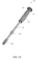
FIG. 16 is a perspective view of one example of an impactor tool, according to this invention;
FIG. 16A is a perspective view of the impactor tool of FIG. 16 holding the bone fusing implant of FIG. 4A;
FIG. 16B is an enlarged implant holder tip of the impactor tool of FIG. 16;
FIG. 17 is a perspective view of one example of an implant inserter tool, according to this invention;
FIG. 18 is a perspective view of another example of an implant inserter tool with an attached implant, according to this invention; and
FIG. 19 is a perspective view of the implant inserter tool of FIG. 18 with a detached implant.
DETAILED DESCRIPTION OF THE INVENTION
The present invention relates to a system and a method for bone fusing implants and implant insertion tools, and more particularly to bone fusing implants that are used for sacroiliac joint fusion.
Referring to FIG. 1, in SIJF surgery one or more openings 92 are formed along the arrow direction 81 and bone fusing implants 100 are inserted in the formed openings 92. Referring to FIG. 1A, bone fusing implant 100A is inserted in opening 92 that is formed through two stacked adjacent bone members 90 a and 90 b. In one example, bone member 90 a is primarily a cortical (compact) bone and bone member 90 b is in majority a cancellous (porous) bone. Referring to FIG. 2A and FIG. 2B, bone implant 100A includes a cylindrical hollow threaded body 110 that has six oval shaped openings 112 a, 112 b, 112 c, 112 d, 112 e, 112 f, a through opening 122 that extends the entire length of the implant and a first segment 130 with cortical threads 132 and a second segment 140 with cancellous threads 142. Cortical threads 132 are closely spaced and have larger core-to-outer diameter ratios than cancellous threads. Screws with cortical threads are used for fixation of cortical (compact) bone. Cancellous threads 142 are cut deep and are widely spaced. Screws with cancellous threads are designed for fixation of cancellous (porous) bone. Since cancellous bone is much less dense than cortical bone, the screw threads cut their path in the bone when the screw is inserted, i.e. cancellous screws are self-tapping. In one example, implant 100A has a length of 35 mm and a diameter of 12 mm. The segment 130 with the cortical threads 132 has a length of 15 mm, which corresponds to the width of the cortical bone 90 a. The segment 140 with the cancellous threads 142 has a length of 20 mm, which corresponds to the width of the cancellous bone 90 b. Through-opening 122 and oval shaped openings 112 a, 112 b, 112 c, 112 d, 112 e, 112 f are used for inserting graft material into the graft area 150. In other examples, bone implant 100A, has a length of 60 mm and includes nine oval-shaped openings 112, as shown in FIG. 3. Bone implant 100A is made of bone, polyetheretherketone (PEEK), Nitinol, metals, titanium, steel, metal composites, biodegradable materials, collagen matrices, synthetic polymers, polysaccharides, calcium minerals, calcium salts, or composites containing calcium or phosphorous naturally or man made.
In another embodiment, bone implant 100B includes a star-shaped hollow elongated body 160 that has a through opening 162 and outer ridges 166, as shown in FIG. 4A and FIG. 4B. The star-shaped elongated body 160 provides increased surface area due to the surface areas provided by ridges 166. The increased surface area contributes to better joint fixation, which minimizes micro-motion and therefore improves bone fusion. In one example, implant 100B has a length of 45 mm, a diameter of 15.5.mm and is made of a titanium rod. The outer surface of the implant may be coated with bone growth enhancing additives such as calcium phosphates, hydroxyapatite, or similar, which provides a textured porous surface. The implant is coated via plasma evaporation of electron beam melting.
Bone fusing implants 100A or 100B are inserted into openings formed through the ilium and the adjacent sacrum. Referring to FIG. 5 (or FIG. 6), openings 92 a, 92 b are formed through the ilium and the adjacent sacrum (or through stacked adjacent bones 90 a, 90 b) by inserting pins 202 a, 202 b via a pin guide tool 200. The relative position, distance, pin depth and orientation of pins 202 a, 202 b is set by the pin guide 200. Referring to FIG. 7, FIG. 8 and FIG. 9, pin guide 200 includes a main body 210, a pin alignment slide 212 and a release lever 218. Main body 210 includes an upper portion 211 and a lower portion 216. Upper portion 211 extends along direction 81 a, perpendicular to the lower portion 216 and has a cylindrical opening 213 that extends along the upper portion 211 and is dimensioned to slidably receive pin 202 a. Below opening 213 there are markings 215 a (S, M, L) indicating the diameter of the implant used. The markings include small (S), medium (M), and large (L). Upper portion 211 also includes a pin lock 214 that secures the position of pin 202 a within opening 213. Lower portion 216 extends perpendicular to direction 81 a and includes a side 216 a with teeth 66. Pin alignment slide 212 includes a through-slot 219 that is shaped and dimensioned to slidably receive the lower portion 216 of the main body 210. Pin alignment slide 212 also includes a cylindrical opening 217 that extends parallel to opening 213 and is dimensioned to slidably receive pin 202 b. Pin alignment slide 212 slides around the lower portion 216 along direction 83 and sets the relative distance 203 between pins 202 a, 202 b. Above opening 217 there are markings 215 b (S, M, L) indicating the distance between pins 202 a and 202 b. The markings include small (S), medium (M), and large (L). The position of pin alignment slide 212 relative to the main body 210 is secured by engaging the lever tip 218 a with teeth 217 along side 216 a of the lower portion 216. Pressing the release lever 218 along direction 82 towards the pin alignment slide 212 disengages the lever tip 218 a from teeth 66, releases the pin alignment slide 218 and allows it to slide around the lower portion 216 along direction 83.
After the insertion of pins 202 a, 202 b, the openings 92 a, 92 b are dilated with dilator 360, shown in FIG. 10A-FIG. 11B. Dilator 360 includes a cylindrical body 362 with a through opening 363 and recessed parallel surfaces 364 a, 364 b. Opening 363 is dimensioned so that the dilator slides over the inserted pins 310. Recessed surfaces 364 a, 364 b have curved upper and lower edges 366. Curved edges 366 are used to push against or pull against them in order to advance the dilator 360 forward or backward. Recessed surfaces 364 a, 364 b also include a depth marker 365 that indicates the bone implant length. In the example of FIG. 10B, the bone implant length is 55 mm.
Dilator 360 is inserted into openings 92 a, 92 b, through a tissue protector 380, as shown in FIG. 12. Referring to FIG. 13A and FIG. 13B, tissue protector 380 includes a tubular hollow cylindrical body 386 that has aggressive teeth 388 at its distal end 386 b. Distal end 386 b includes an angled distal tip that conforms to the ilium from a lateral trajectory. The proximal end 386 a of the cylindrical body 386 includes a ring-shaped surface area 384 surrounding lumen 389. Lumen 389 includes opposite alignment channels 387 that are used to keep instruments that are inserted through the lumen aligned. Alignment channels 387 don't run all the way through the guide, and end about 10 mm from the distal end. A table mount ring 385 extends from an edge of surface area 384. An elongated handle 382 extends sidewise from an edge of the surface area 384, as well. Handle 382 is used for holding the tissue protector 380. Handle 382 is detachable and can be repositioned to a desired location at 8 preset angles. Other tools that are inserted through the tissue protector 380 include implant inserters 250, broaches 300 and impactors 340.
Referring to FIG. 14, a broach tool 300 includes an elongated cylindrical body 302 that includes an impaction area 304 at the proximal end 302 a and alignment pins 305 at the distal end 302 b. Alignment pins 305 interface with the alignment channels 387 of the tissue protector 380. Impaction area 304 is flat and includes a notch 303. Tissue tapping end effectors 308 are removably attached to the distal end 302 b. Tissue tapping end effectors 308 have outer cutting surfaces with various shapes, as shown in FIG. 14 and FIG. 15, and a through opening that is dimensioned to receive the guide wire 310. Guide wire 310 is inserted into the through opening of the end effector 308 via a curved guide wire channel 306 that is formed along the side of the elongated cylindrical body 302. Channel 306 is aligned with notch 303. Channel 306 is shaped and dimensioned to receive the guide wire so that the guide wire is curved away from the impaction surface 304 and away from the user. Cylindrical body 302 also includes a depth marker 320 that indicates the tapping depth.
Referring to FIG. 16, FIG. 16A and FIG. 16B, impactor tool 340 includes an elongated cylindrical body 342 that includes an impaction area 344 at the proximal end 342 a and an impactor tip 348 at the distal end 342 b. Impactor tip 348 is used for holding and impacting a bone implant 100B into a tissue opening. Impactor tip 348 includes alignment pins 346, alignment ribs 349, implant anti-rotation features 347 and friction fit implant holder 343, as shown in FIG. 16B. Alignment pins 346 interface with the alignment channels 387 of the tissue protector 380. Implant 100B is removably attached to the friction fit implant holder 343 and the implant anti-rotation features interface with the star-shaped structure in the top of the implant 100B. Guide wire 310 is inserted into the through opening of the implant 100B via a curved guide wire channel 356 that is formed along the side of the elongated cylindrical body 342. Channel 356 is shaped and dimensioned to received a guide wire so that the guide wire is curved away from the impaction surface 344 and away from the user. Cylindrical body 342 also includes a depth marker 345 that indicates the implant impaction depth.
Referring to FIG. 17, FIG. 18 and FIG. 19, an implant inserter tool 250 includes an elongated cylindrical body 256 that includes an impaction area 254 at the proximal end 256 a, a handle 252, alignment pins 255 and an implant holder 258 a or 258 b at the distal end 256 b. Alignment pins 255 interface with the alignment channels 387 of the tissue protector 380. Implants 100A or 100B are removably attached to the implant holder 258 a or 258 b, respectively, which are shaped and dimensioned to interface with the back structure of the implants. As shown in FIG. 17, implant holder 258 a has a threaded tip that engages inner threads within top opening 122 of implant 100A. Similarly, the threaded tip of implant holder 258 b engages inner threads within top opening 162 of implant 100B. Implant holder 258 b also includes implant anti-rotation features that interface with the star-shaped structure in the top of the implant 100B, as shown in FIG. 19.
In operation, pin guide 210 is used to insert pins 202 a, 202 b into two desired locations and form openings 92 a, 92 b through the ilium and the adjacent sacrum, respectively. The relative position and orientation of pins 202 a, 202 b is set by the pin guide 210. Next, a dilator 360 is inserted over the first or second pin 202 a or 202 b to dilate the tissue around the pins. Next, a tissue protector 380 is inserted over the dilator 360 and the dilator is removed leaving the pin 202 a or 202 b in place to form an opening to the ilium. Next, a cannulated drill is passed through the tissue protector over each of the pins and drilled into the ilium to a desired depth. Next, for implant 101 a, a tap is used to tap threads in the formed opening 92 a prior to inserting implant 101 a. For implant 101 b, a broach 300 is impacted into the bone to generate the opening pattern of implant 101 b. Next, the bone fusing implants 101 a, 101 b are inserted into the corresponding formed openings 92 a, 92 b and the pin guides are removed. The steps are repeated for inserting pins for another implant.
Several embodiments of the present invention have been described. Nevertheless, it will be understood that various modifications may be made without departing from the spirit and scope of the invention. Accordingly, other embodiments are within the scope of the following claims.

Claims (24)

What is claimed is:
1. A method for fusing two adjacent stacked bones comprising:
inserting first and second pins into first and second locations of a first surface of one of the two adjacent stacked bones, respectively;
inserting a dilator over each of the first and second pins to dilate tissue around the first and second pins;
inserting a tissue protector over the dilator and removing the dilator;
inserting a cannulated drill through the tissue protector over each of the first and second pins and drilling first and second openings in the first and second locations, respectively, wherein the first and second opening extend through the two adjacent stacked bones;
tapping threads in the first opening and inserting a first bone fusing implant in the first opening, wherein the first bone fusing implant comprises threads configured to engage the threads of the first opening;
impacting a broach into the second opening to generate a pattern corresponding to a pattern of a second bone fusing implant and then inserting the second bone fusing implant in the second opening; and
removing the first and second pins from the first and second opening, respectively.
2. The method of claim 1, wherein one of the two adjacent stacked bones comprises a cortical bone and the other of the two adjacent stacked bones comprises a cancellous bone and wherein the first bone fusing implant comprises a first segment comprising cortical threads configured to engage threads in the cortical bone and a second segment comprising cancellous threads configured to engage threads in the cancellous bone.
3. The method of claim 2, wherein the cortical threads are closely spaced and have larger core-to-outer diameter ratio than the cancellous threads.
4. The method of claim 2, wherein the cancellous threads are cut deep and are widely spaced.
5. The method of claim 2 wherein the first segment comprises a length equal to the cortical bone width and wherein the second segment comprises a length equal to the cancellous bone width.
6. The method of claim 2, wherein the first bone fusing implant comprises a cylindrical hollow threaded body having a plurality of oval shaped openings and a central through-opening extending the entire length of the cylindrical hollow threaded body.
7. The method of claim 2, wherein the first bone fusing implant comprises one of bone, polyetheretherketone (PEEK), Nitinol, metals, titanium, steel, metal composites, biodegradable materials, collagen matrices, synthetic polymers, polysaccharides, calcium minerals, calcium salts, or composites containing calcium or phosphorous naturally or man made.
8. The method of claim 1, wherein the second bone fusing implant comprises a star-shaped hollow elongated body that has a central through-opening and outer ridges that are configured to engage grooves formed in an inner surface of the second opening.
9. The method of claim 8, wherein an outer surface of the second bone fusing implant is coated with bone growth enhancing additives and wherein the bone growth enhancing additives comprise one of calcium phosphates, or hydroxyapatite.
10. The method of claim 1, wherein the first and second pins are inserted into the first and second locations of the first surface of one of the two adjacent stacked bones via a pin guide tool and wherein the pin guide tool is configured to set relative position, distance, pin depth and pin orientation of the first and second pins.
11. The method of claim 10, wherein the pin guide tool comprises a main body, and a pin alignment slide and wherein the main body comprises an upper portion and a lower portion and wherein the upper portion extends along a first direction perpendicular to the lower portion and comprises a cylindrical through-opening shaped and dimensioned to slidably receive the first pin, and wherein the pin alignment slide comprises a cylindrical through-opening extending parallel to the cylindrical through-opening of the upper portion and being shaped and dimensioned to slidably receive the second pin.
12. The method of claim 11, wherein the upper portion of the main body comprises markings indicating the diameter of the first bone fusing implant and wherein the pin alignment slide comprises markings indicating the diameter of the second bone fusing implant.
13. The method of claim 11, wherein the pin alignment slide comprises a through-slot shaped and dimensioned to slidably receive the lower portion of the main body and wherein the pin alignment slide is configured to set the distance between the first and second pins by sliding along the lower portion of the main body in a direction perpendicular to the first direction.
14. The method of claim 13, wherein the lower portion of the main body comprises a slide with teeth and wherein the pin alignment slide is configured to slide along the slide and the position of the pin alignment slide is secured along the slide by engaging a lever.
15. The method of claim 1, wherein the dilator comprises a cylindrical body with a central through-opening shaped and dimensioned to slide over the first and second pins, and wherein the cylindrical body of the dilator comprises a segment with recessed parallel surfaces, curved upper and lower edges and a depth marker.
16. The method of claim 1, wherein the tissue protector comprises a tubular hollow cylindrical body having a proximal end and an angled distal end and wherein the angled distal end comprises teeth and wherein the proximal end comprises a ring-shaped surface surrounding a lumen and wherein the lumen comprises first and second opposite alignment channels.
17. The method of claim 16, wherein the tissue protector further comprises an elongated detachable handle and a table mount ring extending from an edge of the ring-shaped surface and wherein the elongated detachable handle is configured to be attached to locations around the ring-shaped surface.
18. The method of claim 1, wherein the broach comprises an elongated cylindrical body having an impaction area at a proximal end and alignment pins at a distal end and wherein the broach further comprises a tissue tapping end effector configured to be removably attached to the distal end.
19. The method of claim 18, wherein the impaction area comprises a flat top surface and a side notch.
20. The method of claim 18, wherein the tissue tapping end effector comprises outer cutting surfaces configured to generate the pattern of the second bone fusing implant in the second opening.
21. The method of claim 19, wherein the elongated cylindrical body comprises a curved channel formed along a side surface of the elongated cylindrical body and being configured to receive a guide wire and wherein the curved channel is aligned with the side notch of the impaction area.
22. The method of claim 21, wherein the tissue tapping end effector comprises a through-opening configured to receive the guide wire.
23. The method of claim 18, wherein the cylindrical body further comprises depth markers configured to indicate a tapping depth.
24. The method of claim 1, wherein the first and second bone fusing implants are inserted with an implant inserter tool and wherein the implant inserter tool comprises an elongated cylindrical body, a handle, an impaction area, alignment pins and an implant holder and wherein the impaction area is located at a proximal end of the elongated cylindrical body and the implant holder is attached to a distal end of the elongated cylindrical body and wherein the implant holder comprises structures configured to engage corresponding structures on a proximal end of the first and second bone implants.
US14/485,903 2013-09-16 2014-09-15 System and method for bone fusing implants and implant insertion tools Active 2036-01-26 US9717538B2 (en)

Priority Applications (2)

Application Number Priority Date Filing Date Title
US14/485,903 US9717538B2 (en) 2013-09-16 2014-09-15 System and method for bone fusing implants and implant insertion tools
PCT/US2014/055736 WO2015039063A1 (en) 2013-09-16 2014-09-16 System and method for bone fusing implants and implant insertion tools

Applications Claiming Priority (2)

Application Number Priority Date Filing Date Title
US201361878141P 2013-09-16 2013-09-16
US14/485,903 US9717538B2 (en) 2013-09-16 2014-09-15 System and method for bone fusing implants and implant insertion tools

Publications (2)

Publication Number Publication Date
US20150080972A1 US20150080972A1 (en) 2015-03-19
US9717538B2 true US9717538B2 (en) 2017-08-01

Family

ID=52666396

Family Applications (1)

Application Number Title Priority Date Filing Date
US14/485,903 Active 2036-01-26 US9717538B2 (en) 2013-09-16 2014-09-15 System and method for bone fusing implants and implant insertion tools

Country Status (2)

Country Link
US (1) US9717538B2 (en)
WO (1) WO2015039063A1 (en)

Cited By (3)

* Cited by examiner, † Cited by third party
Publication number Priority date Publication date Assignee Title
US10335216B2 (en) 2011-07-15 2019-07-02 Globus Medical, Inc. Screw implants for bone fusion
US10925653B2 (en) 2011-07-15 2021-02-23 Globus Medical, Inc. Screw implants for bone fusion
US11129655B2 (en) 2018-07-20 2021-09-28 Kic Ventures, Llc System and method for bone fusing implants

Families Citing this family (27)

* Cited by examiner, † Cited by third party
Publication number Priority date Publication date Assignee Title
US9949843B2 (en) 2004-08-09 2018-04-24 Si-Bone Inc. Apparatus, systems, and methods for the fixation or fusion of bone
US20180228621A1 (en) 2004-08-09 2018-08-16 Mark A. Reiley Apparatus, systems, and methods for the fixation or fusion of bone
US9381045B2 (en) * 2010-01-13 2016-07-05 Jcbd, Llc Sacroiliac joint implant and sacroiliac joint instrument for fusing a sacroiliac joint
US9333090B2 (en) 2010-01-13 2016-05-10 Jcbd, Llc Systems for and methods of fusing a sacroiliac joint
US10363140B2 (en) 2012-03-09 2019-07-30 Si-Bone Inc. Systems, device, and methods for joint fusion
US9526547B2 (en) * 2013-03-06 2016-12-27 Rgt Scientific Inc. Bone screw
WO2014146018A1 (en) 2013-03-15 2014-09-18 Jcbd, Llc Systems and methods for fusing a sacroiliac joint and anchoring an orthopedic appliance
US9936983B2 (en) 2013-03-15 2018-04-10 Si-Bone Inc. Implants for spinal fixation or fusion
US9826986B2 (en) 2013-07-30 2017-11-28 Jcbd, Llc Systems for and methods of preparing a sacroiliac joint for fusion
US11147688B2 (en) 2013-10-15 2021-10-19 Si-Bone Inc. Implant placement
US9839448B2 (en) * 2013-10-15 2017-12-12 Si-Bone Inc. Implant placement
US11284798B2 (en) * 2014-05-27 2022-03-29 Jcbd, Llc Systems for and methods of diagnosing and treating a sacroiliac joint disorder
US9801546B2 (en) 2014-05-27 2017-10-31 Jcbd, Llc Systems for and methods of diagnosing and treating a sacroiliac joint disorder
US10166033B2 (en) 2014-09-18 2019-01-01 Si-Bone Inc. Implants for bone fixation or fusion
JP6542362B2 (en) 2014-09-18 2019-07-10 エスアイ−ボーン・インコーポレイテッドSi−Bone, Inc. Matrix implant
US9974573B2 (en) 2014-10-24 2018-05-22 Mis Ip Holdings Llc Minimally invasive approaches, methods and apparatuses to accomplish sacroiliac fusion
US10779811B2 (en) * 2014-12-11 2020-09-22 Smith & Nephew, Inc. Bone anchor having improved fixation strength
US10376206B2 (en) 2015-04-01 2019-08-13 Si-Bone Inc. Neuromonitoring systems and methods for bone fixation or fusion procedures
US10603055B2 (en) 2017-09-15 2020-03-31 Jcbd, Llc Systems for and methods of preparing and fusing a sacroiliac joint
US11116519B2 (en) 2017-09-26 2021-09-14 Si-Bone Inc. Systems and methods for decorticating the sacroiliac joint
US10864029B2 (en) 2018-01-26 2020-12-15 West End Bay Partners, Llc Sacroiliac joint stabilization and fixation devices and related methods
US10905472B2 (en) * 2018-02-28 2021-02-02 Globus Medical, Inc. Method and apparatus for performing medial-to-lateral sacroiliac fusion
US11369419B2 (en) 2019-02-14 2022-06-28 Si-Bone Inc. Implants for spinal fixation and or fusion
EP3923829A4 (en) 2019-02-14 2022-12-14 SI-Bone, Inc. Implants for spinal fixation and or fusion
US11633219B2 (en) * 2019-06-26 2023-04-25 Globus Medical, Inc. Fenestrated pedicle nail
AU2020392121A1 (en) 2019-11-27 2022-06-09 Si-Bone, Inc. Bone stabilizing implants and methods of placement across SI joints
WO2022125619A1 (en) * 2020-12-09 2022-06-16 Si-Bone Inc. Sacro-iliac joint stabilizing implants and methods of implantation

Citations (9)

* Cited by examiner, † Cited by third party
Publication number Priority date Publication date Assignee Title
US5334205A (en) * 1993-06-30 1994-08-02 The United States Of America As Represented By The Secretary Of The Air Force Sacroiliac joint fixation guide
US6159179A (en) 1999-03-12 2000-12-12 Simonson; Robert E. Cannula and sizing and insertion method
US20080147079A1 (en) 2006-12-15 2008-06-19 Spinefrontier Lls Guidance system,tools and devices for spinal fixation
US7494489B2 (en) 2004-05-07 2009-02-24 Jeffrey S. Roh Systems and methods that facilitate minimally invasive spine surgery
US20100004657A1 (en) 2008-01-18 2010-01-07 Spinecore, Inc. Instruments and methods for inserting artificial intervertebral implants
US20100268232A1 (en) 2009-02-12 2010-10-21 Osteotech, Inc. Delivery systems, tools, and methods of use
US7901438B2 (en) 2004-12-08 2011-03-08 Interventional Spine, Inc. Method and apparatus for spinal stabilization
US8388667B2 (en) * 2004-08-09 2013-03-05 Si-Bone, Inc. Systems and methods for the fixation or fusion of bone using compressive implants
US9241798B2 (en) * 2009-03-20 2016-01-26 David A. Petersen Surgical methods and tools

Patent Citations (9)

* Cited by examiner, † Cited by third party
Publication number Priority date Publication date Assignee Title
US5334205A (en) * 1993-06-30 1994-08-02 The United States Of America As Represented By The Secretary Of The Air Force Sacroiliac joint fixation guide
US6159179A (en) 1999-03-12 2000-12-12 Simonson; Robert E. Cannula and sizing and insertion method
US7494489B2 (en) 2004-05-07 2009-02-24 Jeffrey S. Roh Systems and methods that facilitate minimally invasive spine surgery
US8388667B2 (en) * 2004-08-09 2013-03-05 Si-Bone, Inc. Systems and methods for the fixation or fusion of bone using compressive implants
US7901438B2 (en) 2004-12-08 2011-03-08 Interventional Spine, Inc. Method and apparatus for spinal stabilization
US20080147079A1 (en) 2006-12-15 2008-06-19 Spinefrontier Lls Guidance system,tools and devices for spinal fixation
US20100004657A1 (en) 2008-01-18 2010-01-07 Spinecore, Inc. Instruments and methods for inserting artificial intervertebral implants
US20100268232A1 (en) 2009-02-12 2010-10-21 Osteotech, Inc. Delivery systems, tools, and methods of use
US9241798B2 (en) * 2009-03-20 2016-01-26 David A. Petersen Surgical methods and tools

Cited By (5)

* Cited by examiner, † Cited by third party
Publication number Priority date Publication date Assignee Title
US10335216B2 (en) 2011-07-15 2019-07-02 Globus Medical, Inc. Screw implants for bone fusion
US10925653B2 (en) 2011-07-15 2021-02-23 Globus Medical, Inc. Screw implants for bone fusion
US11723703B2 (en) 2011-07-15 2023-08-15 Globus Medical, Inc. Screw implants for bone fusion
US11129655B2 (en) 2018-07-20 2021-09-28 Kic Ventures, Llc System and method for bone fusing implants
US11826084B2 (en) 2018-07-20 2023-11-28 Kic Ventures, Llc System and method for bone fusing implants

Also Published As

Publication number Publication date
WO2015039063A1 (en) 2015-03-19
US20150080972A1 (en) 2015-03-19

Similar Documents

Publication Publication Date Title
US9717538B2 (en) System and method for bone fusing implants and implant insertion tools
US11590002B2 (en) Method and apparatus for minimally invasive insertion of intervertebral implants
US11484419B2 (en) Method and apparatus for minimally invasive insertion of intervertebral implants
US11759329B2 (en) Method and apparatus for minimally invasive insertion of intervertebral implants
US10743913B2 (en) Method and apparatus for minimally invasive insertion of intervertebral implants
US11826084B2 (en) System and method for bone fusing implants
US20160310188A1 (en) Devices and Methods for Sacroiliac Joint Arthrodesis and Fixation
US20140257489A1 (en) Method and apparatus for minimally invasive insertion of intervertebral implants
US20210212833A1 (en) System amd method for bone fusing implants
US20230039837A1 (en) Methods, systems, and apparatuses for spinal fusion

Legal Events

Date Code Title Description
AS Assignment

Owner name: SPINEFRONTIER, INC, MASSACHUSETTS

Free format text: ASSIGNMENT OF ASSIGNORS INTEREST;ASSIGNORS:CHIN, KINGSLEY R.;FRANCIS, RICHARD;HENSHAW, CRAIG;AND OTHERS;SIGNING DATES FROM 20170405 TO 20170625;REEL/FRAME:042818/0672

STCF Information on status: patent grant

Free format text: PATENTED CASE

AS Assignment

Owner name: KIC VENTURES, LLC, MASSACHUSETTS

Free format text: ASSIGNMENT OF ASSIGNORS INTEREST;ASSIGNOR:SPINEFRONTIER, INC;REEL/FRAME:053971/0594

Effective date: 20190701

FEPP Fee payment procedure

Free format text: MAINTENANCE FEE REMINDER MAILED (ORIGINAL EVENT CODE: REM.); ENTITY STATUS OF PATENT OWNER: SMALL ENTITY

FEPP Fee payment procedure

Free format text: SURCHARGE FOR LATE PAYMENT, SMALL ENTITY (ORIGINAL EVENT CODE: M2554); ENTITY STATUS OF PATENT OWNER: SMALL ENTITY

MAFP Maintenance fee payment

Free format text: PAYMENT OF MAINTENANCE FEE, 4TH YR, SMALL ENTITY (ORIGINAL EVENT CODE: M2551); ENTITY STATUS OF PATENT OWNER: SMALL ENTITY

Year of fee payment: 4