US9768463B2 - Aqueous redox flow batteries comprising metal ligand coordination compounds - Google Patents
Aqueous redox flow batteries comprising metal ligand coordination compounds Download PDFInfo
- Publication number
- US9768463B2 US9768463B2 US13/948,497 US201313948497A US9768463B2 US 9768463 B2 US9768463 B2 US 9768463B2 US 201313948497 A US201313948497 A US 201313948497A US 9768463 B2 US9768463 B2 US 9768463B2
- Authority
- US
- United States
- Prior art keywords
- metal
- salt
- flow battery
- independently
- ligand coordination
- Prior art date
- Legal status (The legal status is an assumption and is not a legal conclusion. Google has not performed a legal analysis and makes no representation as to the accuracy of the status listed.)
- Active, expires
Links
Images


Classifications
-
- H—ELECTRICITY
- H01—ELECTRIC ELEMENTS
- H01M—PROCESSES OR MEANS, e.g. BATTERIES, FOR THE DIRECT CONVERSION OF CHEMICAL ENERGY INTO ELECTRICAL ENERGY
- H01M8/00—Fuel cells; Manufacture thereof
- H01M8/18—Regenerative fuel cells, e.g. redox flow batteries or secondary fuel cells
- H01M8/184—Regeneration by electrochemical means
- H01M8/188—Regeneration by electrochemical means by recharging of redox couples containing fluids; Redox flow type batteries
-
- H—ELECTRICITY
- H01—ELECTRIC ELEMENTS
- H01M—PROCESSES OR MEANS, e.g. BATTERIES, FOR THE DIRECT CONVERSION OF CHEMICAL ENERGY INTO ELECTRICAL ENERGY
- H01M8/00—Fuel cells; Manufacture thereof
- H01M8/08—Fuel cells with aqueous electrolytes
-
- H—ELECTRICITY
- H01—ELECTRIC ELEMENTS
- H01M—PROCESSES OR MEANS, e.g. BATTERIES, FOR THE DIRECT CONVERSION OF CHEMICAL ENERGY INTO ELECTRICAL ENERGY
- H01M8/00—Fuel cells; Manufacture thereof
- H01M8/20—Indirect fuel cells, e.g. fuel cells with redox couple being irreversible
-
- H—ELECTRICITY
- H02—GENERATION; CONVERSION OR DISTRIBUTION OF ELECTRIC POWER
- H02J—CIRCUIT ARRANGEMENTS OR SYSTEMS FOR SUPPLYING OR DISTRIBUTING ELECTRIC POWER; SYSTEMS FOR STORING ELECTRIC ENERGY
- H02J7/00—Circuit arrangements for charging or depolarising batteries or for supplying loads from batteries
-
- Y—GENERAL TAGGING OF NEW TECHNOLOGICAL DEVELOPMENTS; GENERAL TAGGING OF CROSS-SECTIONAL TECHNOLOGIES SPANNING OVER SEVERAL SECTIONS OF THE IPC; TECHNICAL SUBJECTS COVERED BY FORMER USPC CROSS-REFERENCE ART COLLECTIONS [XRACs] AND DIGESTS
- Y02—TECHNOLOGIES OR APPLICATIONS FOR MITIGATION OR ADAPTATION AGAINST CLIMATE CHANGE
- Y02E—REDUCTION OF GREENHOUSE GAS [GHG] EMISSIONS, RELATED TO ENERGY GENERATION, TRANSMISSION OR DISTRIBUTION
- Y02E60/00—Enabling technologies; Technologies with a potential or indirect contribution to GHG emissions mitigation
- Y02E60/30—Hydrogen technology
- Y02E60/50—Fuel cells
-
- Y02E60/528—
Definitions
- This disclosure relates to the field of energy storage systems, including electrochemical energy storage systems, batteries, and flow battery systems and methods of operating the same.
- Electrochemical energy storage systems have been proposed for large-scale energy storage. To be effective, these systems must be safe, reliable, low-cost, and highly efficient at storing and producing electrical power.
- Flow batteries compared to other electrochemical energy storage devices, offer an advantage for large-scale energy storage applications owing to their unique ability to decouple the functions of power density and energy density.
- Existing flow batteries have suffered from the reliance on battery chemistries that result in high costs of active materials and system engineering, low cell and system performance (e.g. round trip energy efficiency), poor cycle life, and others.
- Traditional flow battery active materials comprise simple transition metal salts and/or halogen ions as positive
- the overall battery properties energy density, cell voltage, charge/discharge rate, etc
- the negative couples taught by the prior art may each exhibit adequate electromotive force but with poor electrode kinetics (e.g., Cr 3+/2+ ), exhibit modest electromotive force with modest electrode kinetics (e.g., V 3+/2+ ), plate metal onto the negative electrode precluding the decoupling of stack size and discharge time and presenting dendrite growth throughout cycling (e.g., Zn 2+/0 ), or exhibit modest electromotive force and require the management of flammable gas (e.g., H + /H 2 ).
- the redox active metal-ligand coordination compounds described herein provide active materials comprising low-cost, earth abundant elements at useful battery half-cell potentials. Unexpectedly, the materials were discovered to exhibit high solubility (allowing for high energy storage density) and high electromotive forces (e.g., including highly negative potentials) and suitably rapid electrode kinetics that enable operation of energy storage devices at high current densities. Through various choices of certain of these electrolyte, active material, and electrode compositions, flow battery cells are enabled that operate at high cell voltages and with high efficiency.
- Active materials that include a composition of matter described by this invention may be used in energy storage systems in such a way that they are paired with other active materials to form positive couples and negative couples wherein said other active materials are described by the present invention or are previously known in the art or a combination thereof, including those comprising soluble, semi-solid, intercalation, capacitive or pseudo-capacitive, or plating-type active materials. That is, the present invention may be used in both half-cells of an energy storage system or as one half-cell in a system where the other half-cell is, for example, Fe 2+/3+ , Br 2 /Br ⁇ , H + /H 2 , VO 2+ /VO 2 + , or another half-cell.
- each flow battery comprising a first aqueous electrolyte comprising a first redox active material; a second aqueous electrolyte comprising a second redox active material; a first electrode in contact with said first aqueous electrolyte; a second electrode in contact with said second aqueous electrolyte and a separator disposed between said first aqueous electrolyte and said second aqueous electrolyte; wherein each of the first and second redox active materials comprise a metal ligand coordination compound that independently exhibits substantially reversible electrochemical kinetics.
- each flow battery comprising: a first aqueous electrolyte comprising a first redox active material; a second aqueous electrolyte comprising a second redox active material; a first electrode in contact with said first aqueous electrolyte; a second electrode in contact with said second aqueous electrolyte and a separator disposed between said first aqueous electrolyte and said second aqueous electrolyte; wherein the first or second redox active material, or both the first and second redox active materials comprise a metal ligand coordination compound having a formula comprising M(L1) x (L2) y (L3) z m , where M is independently a non-zero valent metal or metalloid of Groups 2-16, including lanthanides and actinides, where x, y, and z are independently 0, 1, 2, or 3 and 1 ⁇ x+y+z ⁇ 3; m is independently ⁇ 5, ⁇ 4, ⁇ 3, ⁇
- Ar is a 5-20 membered aromatic moiety, optionally comprising one of more ring O, N, or S heteroatoms;
- X 1 and X 2 are independently —OH, —NHR′, —SH, or an anion thereof, X 1 and X 2 being positioned ortho to one another;
- R 1 is independently at each occurrence H, C 1-6 alkoxy, C 1-6 alkyl, C 1-6 alkenyl, C 1-6 alkynyl, 5-6 membered aryl or heteroaryl, a boric acid or a salt thereof, carboxy acid or a salt thereof, C 2-6 carboxylate, cyano, halo, hydroxyl, nitro, sulfonate, sulfonic acid or a salt thereof, phosphonate, phosphonic acid or a salt thereof, or a polyglycol (preferably polyethylene glycol, —[CH 2 CH 2 —O] 2-20 —OH, preferably —[CH 2 CH 2 —O]
- Some embodiments provide certain separator characteristics, both in absolute compositional and parametric terms and in relation to the metal ligand coordination compounds. Other embodiments describe specific functional characteristics that derive from the inventive systems.
- each flow battery comprises: a first aqueous electrolyte comprising a first redox active material; a second aqueous electrolyte comprising a second redox active material; a first carbon electrode in contact with said first aqueous electrolyte; a second carbon electrode in contact with said second aqueous electrolyte and a separator disposed between said first aqueous electrolyte and said second aqueous electrolyte; wherein the first, second, or both first and second redox active material comprises a metal ligand coordination complex having a formula comprising M(L1) x (L2) y (L3) z m , M comprises Al, Ca, Ce, Co, Cr, Fe, Mg, Mn, Mo, S, Sn, Ti, W, Zn, or Zr; L1, L2, and L3 are each independently ascorbate, a catecholate, citrate, a glycolate or polyol (including a ligand derived from
- each flow battery comprises: a first aqueous electrolyte comprising a first redox active material; a second aqueous electrolyte comprising a second redox active material; a first electrode in contact with said first aqueous electrolyte; a second electrode in contact with said second aqueous electrolyte and a separator disposed between said first aqueous electrolyte and said second aqueous electrolyte;
- the invention also provides systems, each system comprising a flow battery as described herein, and further comprising:
- each method comprising charging said battery by the input of electrical energy or discharging said battery by the removal of electrical energy.
- each method, with an associated flow of electrons comprises applying a potential difference across the first and second electrode, so as to:
- each method comprises applying a potential difference across the first and second electrode, so as to:
- FIG. 1 depicts a schematic of an exemplary flow battery.
- FIG. 2 provides stability performance data obtained during 250 charge/discharge cycles for a 5 cm 2 system based on Ti 4+/3+ (cat) 3 2 ⁇ /3 ⁇ and Fe 3+/2+ (CN) 6 3 ⁇ /4 ⁇ , as described in Example 2.
- FIG. 3 provides a charge/discharge trace for a flow battery of the present invention as described in Example 2.
- This example contains Ti 4+/3+ (cat) 3 2 ⁇ /3 ⁇ and Fe 3+/2+ (CN) 6 3 ⁇ /4 ⁇ as first and second electrolytes, respectively.
- the battery was charged from 0% SOC to 60% SOC and then discharged to 40% SOC at a current density of 200 mA/cm 2 and a RT Voltage efficiency of ⁇ 76%.
- FIG. 4 provides current efficiency data obtained for a system based on Ti 4+/3+ (cat) 3 2 ⁇ /3 ⁇ and Fe 3+/2+ (CN) 6 3 ⁇ /4 ⁇ , as described in Example 3.
- FIG. 5 provides voltage efficiency data, as a function of current density, for a system based on Ti 4+/3+ (cat) 2 (pyrogallate) 2 ⁇ /3 ⁇ and Fe 3+/2+ (CN) 6 3 ⁇ /4 ⁇ , as described in Example 4.
- FIG. 6 provides voltage efficiency data, as a function of current density, for a system based on Ti 4+/3+ (cat) 3 2 ⁇ /3 ⁇ and Fe 3+/2+ (CN) 6 3 ⁇ /4 ⁇ , as described in Example 4.
- FIG. 7 provides a charge/discharge trace for a flow battery of the present invention.
- This example contains Fe 3+/2+ (cat) 3 3 ⁇ /4 ⁇ and Fe 3+/2+ (CN) 6 3 ⁇ /4 ⁇ as first and second electrolytes, respectively.
- the battery was charged from 0% SOC to 60% SOC and then discharged to 40% SOC at a current density of 100 mA/cm 2 and a RT voltage efficiency of ca. 82%.
- FIG. 8 provides cyclic votammogram, CV traces for Al(cit) 2 (cat) 2 ⁇ /3 ⁇ in pH 11.5 Na 2 SO 4 electrolyte recorded at a glassy carbon electrode.
- FIG. 9 provides CV traces for titanium tris-pyrogallate over a range of operating potentials.
- the data were generated using solutions of 75 mM NaK[Ti(pyrogallate) 3 ] at a pH of 9.8 and 1 M Na 2 SO 4 , recorded at a glassy carbon electrode.
- FIG. 10 provides CV traces for iron tris-catecholate over a range of operating potentials.
- the data were generated using solutions of 1M NaK[Fe(catecholate) 3 ] at a pH of 11, and 3 M Na/KCl, recorded at a glassy carbon electrode.
- FIG. 11 provides a CV trace for titanium bis-catecholate mono-pyrogallate over a range of operating potentials.
- the data were generated using solutions of 1.6 M NaK[Ti(catecholate) 2 (pyrogallate)] at a pH of 11, recorded at a glassy carbon electrode.
- FIG. 12 provides a CV trace for titanium bis-catecholate monolactate over a range of operating potentials.
- the data were generated using solutions of 0.75 M NaK[Ti(catecholate) 2 (lactate)] at a pH of 9, recorded at a glassy carbon electrode.
- FIG. 13 provides a CV trace for titanium bis-catecholate mono-gluconate over a range of operating potentials.
- the data were generated using solutions of 1.5 M NaK[Ti(catecholate) 2 (gluconate)] at a pH of 9, recorded at a glassy carbon electrode.
- FIG. 14 provides a CV trace for titanium bis-catecholate mono-ascorbate over a range of operating potentials.
- the data were generated using solutions of 1.5 M NaK[Ti(catecholate) 2 (ascorbate)] at a pH of 10, recorded at a glassy carbon electrode.
- FIG. 15 provides a CV trace for titanium tris-catecholate over a range of operating potentials.
- the data were generated using solutions of 1.5 M Na 2 -[Ti(catecholate) 3 ] at a pH of 11, recorded at a glassy carbon electrode.
- FIG. 16 provides a CV trace for titanium mono-catecholate mono-pyrogallate mono-lactate over a range of operating potentials.
- the data were generated using solutions of 1.5 M NaK[Ti(catecholate)(pyrogallate)(lactate)] at a pH of 8.5, recorded at a glassy carbon electrode.
- FIG. 17 provides a CV trace for titanium tris-citrate over a range of operating potentials.
- the data were generated using solutions of 0.5 M Na 4 -[Ti(citrate) 3 ] at a pH of 5, recorded at a platinum disk electrode.
- FIG. 18 provides a CV trace from a solution of 1.5 M [Fe(CN) 6 ] 4 ⁇ obtained at a glassy carbon disk working electrode at several scan rates using 0.1 M sodium potassium hydrogen phosphate as the supporting electrolyte, as described in Example 5.11.
- the ratio of Na + /K + counterions in this example was ca. 1:1.
- FIG. 19 provides a CV trace for chromium hexacyanide over a range of operating potentials.
- the data were generated using solutions of 0.05 M K 3 -[Cr(CN) 6 ] at a pH of 9, recorded at a glassy carbon electrode.
- FIG. 20 provides a CV trace for manganese hexacyanide over a range of operating potentials.
- the data were generated using solutions of 0.1 M K 3 [Mn(CN) 6 ] at a pH of 9, recorded at a glassy carbon electrode.
- FIG. 21 provides data for cell voltage during charge-discharge cycling for 1 M Fe(CN) 6 as positive couple and 1 M Ti(lactate) 2 (salicylate) as negative couple, both at pH 11, in a 5 cm 2 active area flow battery at a current density of 150 mA/cm 2 except for the area noted as 100 mA/cm 2 .
- FIG. 22 provides cell voltage in volts plotted versus test time in hours during charge-discharge cycling and iV traces between each cycle for 1 M Fe(CN) 6 as positive couple and 1 M Ti(lactate) 2 ( ⁇ -hydroxyacetate) as negative couple, both at pH 11, in a 5 cm 2 active area flow battery at a current density of 150 mA/cm 2 .
- FIG. 23 provides CV traces for 10 mM titanium tris-salicylate at pH 8.6 over a range of operating potentials at a glassy carbon electrode with NaKSO 4 supporting electrolyte.
- FIG. 24 provides CV traces for 1 M iron tris-salicylate at pH 9.3 over a range of operating potentials, recorded at a glassy carbon electrode with NaKSO 4 supporting electrolyte
- FIG. 25 provides CV traces for 10 mM titanium mono-lactate at pH 5.6 over a range of operating potentials, recorded at a glassy carbon electrode with NaKSO 4 supporting electrolyte.
- FIG. 26 provides CV traces for 1 M titanium mono-lactate at pH 9 over a range of operating potentials, recorded at a glassy carbon electrode with NaKSO 4 supporting electrolyte.
- FIG. 27 provides CV traces for 1 M titanium bis-lactate at pH 2 over a range of operating potentials, recorded at a glassy carbon electrode with Na 2 SO 4 supporting electrolyte.
- FIG. 28 provides CV traces for 1 M titanium bis-lactate at pH 3.6 over a range of operating potentials, recorded at a glassy carbon electrode with NaKSO 4 supporting electrolyte.
- FIG. 29 provides CV traces for 0.75 M titanium bis-lactate at pH 9 over a range of operating potentials, recorded at a glassy carbon electrode with NaKSO 4 supporting electrolyte.
- FIG. 30 provides CV traces for 100 mM titanium-bis-malate-mono-lactate at pH 9.9 over a range of operating potentials, recorded at a glassy carbon electrode with NaKSO 4 supporting electrolyte.
- FIG. 31 provides CV traces for 200 mM titanium-bis-malate-mono-salicylate at pH 10 over a range of operating potentials, recorded at a glassy carbon electrode with NaKSO 4 supporting electrolyte.
- FIG. 32 provides CV traces for 0.5 M titanium bis-lactate mono-glycinate at pH 9.9 over a range of operating potentials, recorded at a glassy carbon electrode with NaKSO 4 supporting electrolyte.
- FIG. 33 provides CV traces for 0.5 M titanium bis-lactate mono-salicylate at pH 10 over a range of operating potentials, recorded at a pH of 9.3 at a glassy carbon electrode with NaKSO 4 supporting electrolyte.
- FIG. 34 provides CV traces for 0.5 M titanium bis-salicylate mono-lactate at pH 9.8 over a range of operating potentials, recorded at a glassy carbon electrode with NaKSO 4 supporting electrolyte.
- FIG. 35 provides CV traces for 200 mM titanium bis-( ⁇ -hydroxyacetate) mono-salicylate over a range of operating potentials, recorded at a pH of 10 at a glassy carbon electrode with NaKSO 4 supporting electrolyte.
- FIG. 36 provides CV traces for 0.5 M titanium bis-( ⁇ -hydroxyacetate) mono-lactate at pH 10 over a range of operating potentials at a glassy carbon electrode with NaKSO 4 supporting electrolyte.
- FIG. 37 provides CV traces for 1 M iron tris-malate at pH 9.2 over a range of operating potentials, recorded at a glassy carbon electrode with NaKSO 4 supporting electrolyte.
- FIG. 38 provides CV traces for 1.5 M iron tris-( ⁇ -hydroxyacetate) at pH 8.1 over a range of operating potentials, recorded at a glassy carbon electrode with NaKSO 4 supporting electrolyte.
- FIG. 39 provides CV traces for 1 M iron mono-lactate at pH 3.1 over a range of operating potentials, recorded at a glassy carbon electrode with NaKSO 4 supporting electrolyte.
- FIG. 40 provides CV traces for 1.5 M iron bis-lactate at pH 2.6 over a range of operating potentials, recorded at a glassy carbon electrode with NaKSO 4 supporting electrolyte.
- FIG. 41 provides CV traces for 1 M iron mono-lactate bis-glycinate at pH 6.7 over a range of operating potentials, recorded at a glassy carbon electrode with NaKSO 4 supporting electrolyte.
- Electrochemical energy storage systems typically operate through the interconversion of electrical and chemical energy.
- Various embodiments of electrochemical energy storage systems include batteries, capacitors, reversible fuel cells and the like, and the present invention may comprise any one or combination of these systems.
- flow batteries transport (e.g., via pumping) redox active energy storage materials from storage tanks through an electrochemical stack, as in exemplary FIG. 1 , which is described elsewhere herein in further detail.
- This design feature decouples the electrical energy storage system power (kW) from the energy storage capacity (kWh), allowing for considerable design flexibility and cost optimization.
- the separator provides several functions which include, e.g., (1) serving as a barrier to mixing of first and second electrolytes; (2) electronically insulating to reduce or prevent short circuits between the positive and negative electrodes; and (3) to provide for ion transport between the positive and negative electrolyte chambers, thereby balancing electron transport during charge and discharge cycles.
- the negative and positive electrodes provide a surface for electrochemical reactions during charge and discharge. During a charge or discharge cycle, electrolytes may be transported from separate storage tanks through the corresponding electrolyte chambers.
- a charging cycle electrical power is applied to the system wherein the active material contained in the second electrolyte undergoes a one-or-more electron oxidation and the active material in the first electrolyte undergoes a one-or-more electron reduction.
- the second electrolyte is reduced and the first electrolyte is oxidized producing electrical power.
- each flow battery comprising:
- the term “substantially reversible electrochemical kinetics” refers to the condition wherein the voltage difference between the anodic and cathodic peaks is less than about 0.3 V, as measured by cyclic voltammetry, using an ex-situ apparatus comprising a flat glassy carbon disc electrode and recording at 100 mV/s.
- additional embodiments provide that the voltage difference between the anodic and cathodic peaks is less than about 0.2 V, less than about 0.1 V, less than about 0.075 V, or less than about 0.059 V, under these same testing conditions.
- Certain aspects of the invention also provide flow batteries, each of which comprises:
- first and second aqueous electrolytes each comprises a first and second metal ligand coordination compound, respectively
- the first and second metal ligand coordination compounds may either be the same or different.
- first or the second or both the first and second metal ligand coordination compound comprises at least one ligand having a structure according to Formula I.
- metal ligand coordination compounds may comprise at least one ligand having a structure according to Formula IA, IB, or IC:
- metal ligand coordination compounds comprises at least one ligand having a structure according to Formula IA, IB, or IC, but where:
- metal coordination compounds described in the broadest context above have been described in terms of non-zero valent metal or metalloid of Groups 2-16, including the lanthanide and actinide elements, additional embodiments provide that these metals may include non-zero valent Al, Ca, Ce, Co, Cr, Fe, Mg, Mn, Mo, Si, Sn, Ti, W, Zn, or Zr, for example Al 3+ , Ca 2+ , Ce 4+ , Co 3+ , Cr 3+ , Fe 3+ , Mg 2+ , Mn 3+ , Mo 6+ , Si 4+ , Sn 4+ , Ti 4+ , W 6+ , Zn 2+ , or Zr 4+ .
- the first and second metal coordination compound may comprise the same or different non-zero valent metal or metalloid, or the same element having a redox couple of differing oxidation states.
- Metal ligand coordination compounds comprising Al, Cr, Ti, Mn, or Fe are preferred, in either or both of the first or second compounds.
- the second metal ligand coordination compound comprises an iron hexacyanide compound, for example as a ferro-/ferricyanide couple.
- the present invention also provides that either or both of the first or the second metal ligand coordination compound are present in the first or second electrolyte, respectively, at elevated concentrations, for example at least about 0.5 M, at least about 0.6 M, at least about 0.75 M, or at least about 1 M. Higher concentrations are preferred for yielding higher system energy densities.
- the energy density of the electrolytes is at least about 10 Wh/L, at least about 20 Wh/L, or at least about 30 Wh/L.
- the individual embodiments described herein also include those where either or both, preferably both, of the first and second metal ligand coordination compounds each exhibit substantially reversible electrochemical kinetics.
- the flow batteries described herein, whether or not dependent on the specific metal ligand combinations described are capable of providing (and do provide when operating) high round trip voltage and current efficiencies, each of at least 70%, when measured at 200 mA/cm 2 and such performance features are considered individual embodiments of the present invention.
- the present invention provides flow batteries capable of operating, or operating, with a current density of at least about 100 mA/cm 2 and a round trip voltage efficiency of at least about 70%, at least about 80%, or at least about 90%.
- flow batteries each comprise:
- L1, L2, and L3 are said to be independently ascorbate, a catecholate, citrate, a glycolate or polyol (including ligands derived from ethylene glycol, propylene glycol, or glycerol), gluconate, glycinate, ⁇ -hydroxyalkanoate (e.g., ⁇ -hydroxyacetate, from glycolic acid), ⁇ -hydroxyalkanoate, ⁇ -hydroxyalkanoate, malate, maleate, phthalate, sarcosinate, salicylate, or lactate, it should be appreciated that these ligands are reflective of a broader class of ligands—i.e., those including aliphatic polyhydroxy, carboxylic, polycarboxylic, or mixed hydroxy-carboxylic species capable of binding, preferably as bi-, tri-, or polydentate chelants, including C 2 -C 10 ⁇ -, ⁇ -, and ⁇ -hydroxy- or polyhydroxycarboxylic acids
- Coordination compounds containing this broader class of ligands are also considered within the scope of the present invention, especially when those coordination compounds also contain at least one catecholate or pyrogallate ligand, at least one polyhydroxy or polycarboxylate, ⁇ - and/or ⁇ -hydroxycarboxylic acid ligand.
- flow batteries each comprise:
- flow batteries each comprise:
- flow batteries each comprise:
- flow batteries each comprise:
- flow batteries each comprise
- the flow batteries include those where either the first or the second or both the first and second metal ligand coordination compound comprises at least one ligand having a structure according to Formula I. In other embodiments, either one or both of the metal ligand coordination compounds comprises at least one ligand having a structure according to Formula IA, IB, or IC:
- the second metal ligand coordination compound may comprise (a) at least one catecholate or pyrogallate ligand, (b) at least one ascorbate, citrate, a glycolate or polyol (including a ligand derived from ethylene glycol, propylene glycol, or glycerol), gluconate, glycinate, ⁇ -hydroxyalkanoate (e.g., ⁇ -hydroxyacetate, from glycolic acid), ⁇ -hydroxyalkanoate, ⁇ -hydroxyalkanoate, malate, maleate, phthalate, sarcosinate, salicylate, or lactate ligand, or (c) both at least one catecholate or pyrogallate ligand, and at least one ascorbate, citrate, a glycolate or polyol (including a ligand derived from ethylene glycol, propylene glycol, or glycerol), gluconate, glycinate, ⁇ -hydroxyalkanoate (e)
- At least one metal ligand coordination compound is a chromium, iron, manganese, molybdenum, or ruthenium cyanide compound, preferably a chromium, iron, or manganese hexacyanide, such as ferricyanide or ferrocyanide in combination another metal ligand coordination compound as described herein.
- the invention further contemplates those embodiments within the scope of Groups A-F, wherein the first and second metal ligand coordination compounds each exhibit substantially reversible electrochemical kinetics.
- system comprises at least two of the flow batteries described herein.
- a flow battery system may include an electrochemical cell that features a separator 20 (e.g., a membrane) that separates the two electrodes of the electrochemical cell.
- Electrode 10 is suitably a conductive material, such as a metal, carbon, graphite, and the like.
- Tank 50 may contain first redox material 30 , which material is capable of being cycled between an oxidized and reduced state.
- FIG. 1 depicts a specific, non-limiting embodiment of a flow battery. Accordingly, devices according to the present disclosure may or may not include all of the aspects of the system depicted in FIG. 1 .
- a system according to the present disclosure may include active materials that are solid, liquid, or gas and/or solids, liquids, or gases dissolved in solution or slurries. Active materials may be stored in a tank, in a vessel open to the atmosphere, or simply vented to the atmosphere.
- a user may desire to provide higher charge or discharge voltages than available from a single battery.
- several batteries are connected in series such that the voltage of each cell is additive.
- An electrically conductive, but non-porous material e.g., a bipolar plate
- the positive electrode compartments and negative electrode compartments of individual cells are suitably fluidically connected via common positive and negative fluid manifolds in the stack. In this way, individual electrochemical cells can be stacked in series to yield a desired operational voltage.
- the cells, cell stacks, or batteries are incorporated into larger energy storage systems, suitably including piping and controls useful for operation of these large units.
- Piping, control, and other equipment suitable for such systems are known in the art, and include, for example, piping and pumps in fluid communication with the respective electrochemical reaction chambers for moving electrolytes into and out of the respective chambers and storage tanks for holding charged and discharged electrolytes.
- the energy storage and generation systems described by the present disclosure may also include electrolyte circulation loops, which may comprise one or more valves, one or more pumps, and optionally a pressure equalizing line.
- the energy storage and generation systems of this disclosure can also include an operation management system.
- the operation management system may be any suitable controller device, such as a computer or microprocessor, and may contain logic circuitry that sets operation of any of the various valves, pumps, circulation loops, and the like.
- a flow battery system may comprise a flow battery (including a cell or cell stack), a first chamber containing the first aqueous electrolyte and a second chamber containing the second aqueous electrolyte; at least one electrolyte circulation loop in fluidic communication each electrolyte chamber, said at least one electrolyte circulation loop comprising storage tanks and piping for containing and transporting the electrolytes; control hardware and software (which may include safety systems); and an optional power conditioning unit.
- the flow battery cell stack accomplishes the conversion of charging and discharging cycles and determines the peak power of energy storage system, which power may in some embodiments be in the kW range.
- the storage tanks contain the positive and negative active materials; the tank volume determines the quantity of energy stored in the system, which may be measured in kWh.
- the control software, hardware, and optional safety systems suitably include sensors, mitigation equipment and other electronic/hardware controls and safeguards to ensure safe, autonomous, and efficient operation of the flow battery energy storage system. Such systems are known to those of ordinary skill in the art.
- a power conditioning unit may be used at the front end of the energy storage system to convert incoming and outgoing power to a voltage and current that is optimal for the energy storage system or the application. For the example of an energy storage system connected to an electrical grid, in a charging cycle the power conditioning unit would convert incoming AC electricity into DC electricity at an appropriate voltage and current for the electrochemical stack. In a discharging cycle, the stack produces DC electrical power and the power conditioning unit converts to AC electrical power at the appropriate voltage and frequency for grid applications.
- non-limiting examples of such applications include those where systems of the present disclosure are connected to an electrical grid include, so as to allow renewables integration, peak load shifting, grid firming, baseload power generation consumption, energy arbitrage, transmission and distribution asset deferral, weak grid support, and/or frequency regulation.
- Cells, stacks, or systems according to the present disclosure may be used to provide stable power for applications that are not connected to a grid, or a micro-grid, for example as power sources for remote camps, forward operating bases, off-grid telecommunications, or remote sensors.
- Flow battery energy storage efficacy is determined by both the round trip DC-DC energy efficiency (RT EFF ) and the energy density of the active materials (measured in Wh/L).
- the RT EFF is a composite of voltage and current efficiencies for both the battery charge and discharge cycles.
- voltage and current efficiencies are functions of the current density, and while voltage and current efficiency typically decrease as current density (mA/cm 2 ) increases, high current densities are often desirable to reduce electrochemical stack size/cost required to achieve a given power rating.
- active material is well known to those skilled in the art of electrochemistry and electrochemical energy storage and is meant to refer to materials which undergo a change in oxidation state during operation of the system.
- Active materials may comprise a solid, liquid, or gas and/or solids, liquids, or gasses dissolved in solution.
- active materials comprise molecules and/or supramolecules dissolved in solution.
- Active materials with a composition of matter described by this invention may be used in energy storage systems in such a way that they are paired with other active materials to form a positive couple and a negative couple wherein said other active materials are described by the present invention or are previously known in the art or a combination thereof, inclusive of soluble, semi-solid, intercalation, capacitive or pseudo-capacitive, and plating-type active materials.
- the concentration of the molecules may be at least about 2 M, between about 1 M and about 2 M, about 1.5 M, between 0.5 M and 1M, or 0.5 M or less.
- the active material may comprise a “metal ligand coordination compound,” which are known to those skilled in the art of electrochemistry and inorganic chemistry.
- a metal ligand coordination compound may comprise a metal ion bonded to an atom or molecule.
- the bonded atom or molecule is referred to as a “ligand”.
- the ligand may comprise a molecule comprising C, H, N, and/or O atoms.
- the ligand may comprise an organic molecule.
- the metal ligand coordination compounds of the present disclosure are understood to comprise at least one ligand that is not water, hydroxide, or a halide (F ⁇ , Cr ⁇ , Br ⁇ , I ⁇ ).
- M(L1) x (L2) y (L3) z m , x, y, and z are independently 0, 1, 2, or 3, such that 1 ⁇ x+y+z ⁇ 3” it should be appreciated that this reflects independent embodiments where “M” contains 1, 2, or 3 ligands of L1, L2, and L3 within its inner coordination sphere, where L1, L2, and L3 are different from one another.
- Metal ligand coordination compounds may comprise a “redox active metal ion” and/or a “redox inert metal ion”.
- the term “redox active metal ion” is intended to connote that the metal undergoes a change in oxidation state under the conditions of use.
- the term “redox inert” metal ion is intended to connote that the metal does not undergo a change in oxidation state under the conditions of use.
- Metal ions may comprise non-zero valence salts of, e.g., Al, Ca, Co, Cr, Sr, Cu, Fe, Mg, Mn, Mo, Ni, Pd, Pt, Ru, Sn, Ti, Zn, Zr, V, or a combination thereof. The skilled artisan would be able to recognize the circumstances where a given non-zero valence metal would be redox active or inactive under the prescribed electrolyte environments.
- the active material may comprise an “organic active material”.
- An organic active material may comprise a molecule or supramolecule that does not contain a transition metal ion. It is further understood that organic active materials are meant to comprise molecules or supramolecules that are dissolved in aqueous solution. And organic active material is capable of undergoing a change in oxidation state during operation of the electrochemical energy storage system. In this case, the molecule or supramolecule may accept or donate an electron during operation of the system.
- aqueous refers to a solvent system comprising at least about 98% by weight of water, relative to total weight of the solvent.
- soluble, miscible, or partially miscible (emulsified with surfactants or otherwise) co-solvents may also be usefully present which, for example, extend the range of water's liquidity (e.g., alcohols/glycols).
- additional independent embodiments include those where the “aqueous” solvent system comprises at least about 55%, at least about 60 wt %, at least about 70 wt %, at least about 75 wt %, at least about 80%, at least about 85 wt %, at least about 90 wt %, at least about 95 wt %, or at least about 98 wt % water, relative to the total solvent.
- the aqueous solvent may consist essentially of water, and be substantially free or entirely free of co-solvents or other species.
- the solvent system may be at least about 90 wt %, at least about 95 wt %, or at least about 98 wt % water, and, in some embodiments, be free of co-solvents or other species.
- the aqueous electrolytes may contain additional buffering agents, supporting electrolytes, viscosity modifiers, wetting agents, and the like.
- bipolar plate refers to an electrically conductive, substantially nonporous material that may serve to separate electrochemical cells in a cell stack such that the cells are connected in series and the cell voltage is additive across the cell stack.
- the bipolar plate has two surfaces such that one surface of the bipolar plate serves as a substrate for the positive electrode in one cell and the negative electrode in an adjacent cell.
- the bipolar plate typically comprises carbon and carbon containing composite materials.
- cell potential is readily understood by those skilled in the art of electrochemistry and is defined to be the voltage of the electrochemical cell during operation.
- E° E° ⁇ RT/nF ln ( X red /X ox ) (3)
- R the universal gas constant
- T temperature
- n the number of electrons transferred in the redox couple of interest
- F Faraday's constant
- X red /X ox is the ratio of reduced to oxidized species at the electrode.
- the OCV of a battery system may be measured by using standard techniques when the current flow between the first and second electrode is equal to zero. In this condition, the voltage difference between the first and second electrodes corresponds to the OCV.
- the OCV of a battery system depends on the state of charge (SOC) of said system. Without being bound to the correctness of any theory, the OCV of an ideal battery, will change with state of charge according to the Nernst equation (equation 4 above). For simplicity in this application all OCVs will be referenced to their values at 50% SOC. Those of ordinary skill in the art will recognize that at higher SOCs the OCV of a battery will increase, and at lower SOCs the OCV will decrease from the value at 50% SOC.
- current density refers to the total current passed in an electrochemical cell divided by the geometric area of the electrodes of the cell and is commonly reported in units of mA/cm 2 .
- current densities may be in a range of from about 50 mA/cm 2 , from about 100 mA/cm 2 or from about 200 mA/cm 2 , to about 200 mA/cm 2 , to about 300 mA/cm 2 , to about 400 mA/cm 2 , or to about 500 mA/cm 2 , and these ranges may also apply to those embodiments referred to as providing “at least 100 mA/cm 2 .”
- I EFF current efficiency
- I EFF current efficiency
- the charge produced on discharge or passed on charge can be measured using standard electrochemical coulomb counting techniques well known to those of ordinary skill in the art. Without being bound by the limits of any theory, the current efficiency may be a function of the state of charge of the flow battery. In some non-limiting embodiments the current efficiency can be evaluated over an SOC range of about 35% to about 60%.
- Energy density refers to the amount of energy that may be stored, per unit volume, in the active materials.
- RT EFF V EFF,RT ⁇ I EFF (7)
- the term “evolution current” describes the portion of the electrical current applied in an energized flow battery configuration which is associated with the evolution (generation) of a particular chemical species.
- evolution current describes the portion of the electrical current applied in an energized flow battery configuration which is associated with the evolution (generation) of a particular chemical species.
- a sufficient overpotential vide infra is applied in a flow battery such that either or both oxygen evolves at the positive electrode or hydrogen evolves at the negative electrode, that portion of the current associated with the evolution of oxygen or hydrogen is the oxygen evolution current or hydrogen evolution current, respectively.
- the batteries operates within 0.3 V, within 0.25 V, within 0.2 V, within 0.15 V, or within 0.1 V of either the thermodynamic threshold potential or the threshold overpotential of the respective positive or negative electrodes.
- the portion of current associated with gas evolution is suitably less than about 20%, less than about 15%, less than about 10%, less than about 5%, less than about 2%, or less than about 1% of the total applied current.
- Lower gas evolution currents are considered particularly suitable for battery (cell or cell stack) efficiencies.
- excluding refers to the ability of a separator to not allow certain ions or molecules to flow through the separator and typically is measured as a percent.
- mobile ion is understood by those skilled in the art of electrochemistry and is meant to comprise the ion which is transferred between the negative and positive electrode during operation of the electrochemical energy storage system.
- the term “mobile ion” may also refer to as an ion that carries at least at least 80% of the ionic current during charger/discharge.
- the terms “negative electrode” and “positive electrode” are electrodes defined with respect to one another, such that the negative electrode operates or is designed or intended to operate at a potential more negative than the positive electrode (and vice versa), independent of the actual potentials at which they operate, in both charging and discharging cycles.
- the negative electrode may or may not actually operate or be designed or intended to operate at a negative potential relative to the reversible hydrogen electrode.
- the negative electrode is associated with the first aqueous electrolyte and the positive electrode is associated with the second electrolyte, as described herein.
- overpotential is well understood by those skilled in the art of electrochemistry and is defined by the difference in voltage between an electrode during operation of an electrochemical cell and the normal half-cell potential of that electrode, as defined by the Nernst equation. Without being bound by theory, the term overpotential is meant to describe the energy, in excess of that required by thermodynamics, to carry out a reaction at a given rate or current density.
- overpotential also describes a potential more positive than the thermodynamic onset voltage for oxygen evolution from water at the positive electrode and more negative than the thermodynamic onset voltage for hydrogen evolution from water at the negative electrode.
- the term “threshold overpotential” refers to the overpotential at which either hydrogen or oxygen gas begins to evolve at the respective electrode.
- an electrochemical system comprising “imperfect” (i.e., less than ideal catalytically) electrodes can be operated in three regions: (a) at a potential “below” the thermodynamic onset potential (i.e., more positive than the thermodynamic onset potential of the negative electrode and more negative than the thermodynamic onset potential of the positive electrode; no gas evolving so no gas evolution current); (b) at a potential between the thermodynamic threshold potential and threshold overpotential (no gas evolving and still no evolution current); and (c) beyond the threshold overpotential (gas evolving and exhibiting a gas evolution current).
- threshold overpotentials can be identified by those skilled in the art for a given system, for example, by measuring gas evolution as a function of applied half-cell potential (using e.g., a mass spectrometer), in the presence or absence of an electroactive material. See also below.
- first or second or both first and second electrolytes comprise at least one compound increases the hydrogen or oxygen threshold overpotential of the system, respectively.
- regenerative fuel cell or “reversible fuel cell” or “flow battery” or “flow energy device” connote the same or similar type of device, which utilizes the same battery configuration (including cell or cell stack) for both energy storage and energy generation.
- RHE reversible hydrogen electrode
- RHE reversible hydrogen electrode
- E(RHE) The potential of the RHE, E(RHE) corresponds to the potential for Equation 8: 2 H + +2 e ⁇ H 2 (8)
- Equation 8 When the reaction of Equation 8 is carried out at equilibrium at a given pH and 1 atm H 2 .
- a potential of 0 V vs. RHE corresponds to a voltage of 0 V vs. NHE at pH 0 and ⁇ 0.413 V vs. NHE at pH 7.
- selectivity is well known to those of ordinary skill in the art of electrochemistry and refers to the ability of a membrane to allow a ratio of the movement of mobile ions to active materials through a membrane. For example, a membrane that allows a 50:1 ratio of mobile ions to active materials to pass through would have a selectivity of 50.
- separator and “membrane” refer to an ionically conductive, electrically insulating material disposed between the positive and negative electrode of an electrochemical cell.
- the polymer electrolytes useful in the present disclosure may be anion or cation conducting electrolytes.
- an “ionomer” refers to a polymer comprising both electrically neutral and a fraction of ionized repeating units, wherein the ionized units are pendant and covalently bonded to the polymer backbone.
- the fraction of ionized units may range from about 1 mole percent to about 90 mole percent, but may be further categorized according to their ionized unit content. For example, in certain cases, the content of ionized units are less than about 15 mole percent; in other cases, the ionic content is higher, typically at least about 80 mole percent.
- Ionized ionomer units may comprise anionic functional groups comprising carboxylates, sulfonates, phosphonates, salts of a carboxy acid, sulfonic acid, phosphonic acid, and the like. These functional groups can be charge balanced by, mono-, di-, or higher-valent cations, such as alkali or alkaline earth metals. Ionomers may also include polymer compositions containing attached or embedded quaternary ammonium, sulfonium, phosphazenium, and guanidinium residues or salts.
- the polymers useful in the present disclosure may comprise highly fluorinated or perfluorinated polymer backbones.
- Certain polymer electrolytes useful in the present disclosure include copolymers of tetrafluoroethylene and one or more fluorinated, acid-functional co-monomers, which are commercially available as NAFIONTM perfluorinated polymer electrolytes from E. I. du Pont de Nemours and Company, Wilmington Del.
- Other useful perfluorinated electrolytes comprise copolymers of tetrafluoroethylene (TFE) and FSO 2 —CF 2 CF 2 CF 2 CF 2 —O—CF ⁇ CF 2 .
- stack or “cell stack” or “electrochemical cell stack” refers to a collection of individual electrochemical cells that are in electrically connected.
- the cells may be electrically connected in series or in parallel.
- the cells may or may not be fluidly connected.
- SOC state of charge
- concentration ratio of reduced to oxidized species at an electrode X red /X ox
- the SOC for a full cell depends on the SOCs of the individual half-cells and in certain embodiments the SOC is the same for both positive and negative electrodes. Measurement of the cell potential for a battery at OCV, and using Equations 2 and 3 the ratio of X red /X ox at each electrode can be determined, and therefore the SOC for the battery system.
- supporting electrolyte is well-known in the arts of electrochemistry and energy storage, and is intended to refer to any species which is redox inactive in the window of electric potential of interest and aids in supporting charge and ionic conductivity. In the present case, a supporting electrolyte does not substantially compromise the solubility of the coordination compound or complex.
- Non-limiting examples include salts comprising an alkali metal, ammonium ion including an ammonium ion partially or wholly substituted by alkyl or aryl groups, halide (e.g., Cl ⁇ , Br ⁇ , I ⁇ ), chalcogenide, phosphate, hydrogen phosphate, phosphonate, nitrate, sulfate, nitrite, sulfite, perchlorate, tetrafluoroborate, hexafluorophosphate, or a mixture thereof, and others known in the art.
- halide e.g., Cl ⁇ , Br ⁇ , I ⁇
- chalcogenide e.g., boronate, phosphonate, nitrate, sulfate, nitrite, sulfite, perchlorate, tetrafluoroborate, hexafluorophosphate, or a mixture thereof, and others known in the art.
- the term “voltage efficiency” may be described as the ratio of the observed electrode potential, at a given current density, to the half-cell potential for that electrode (x 100%), wherein the half-cell potential is calculated as described above. Voltage efficiencies can be described for a battery charging step, a discharging step, or a “round trip voltage efficiency”.
- the present disclosure provides a variety of technical features of the disclosed systems and methods. It should be understood that any one of these features may be combined with any one or more other features. For example, a user might operate a system featuring an electrolyte that includes an organic active material (e.g., a quinone), wherein that electrode has a pH of about 3. Such a system might also feature a membrane separator having a thickness of about 35 microns. It should be further understood that the present disclosure is not limited to any particular combination or combinations of the following features.
- an organic active material e.g., a quinone
- the present invention also provides methods of operating the flow batteries described herein, each method comprising charging said battery by the input of electrical energy or discharging said battery by the removal of electrical energy. Further embodiments provide applying a potential difference across the first and second electrode, with an associated flow of electrons, so as to: (a) reduce the first redox active material while oxidizing the second redox active material; or (b) oxidize the first redox active material while reducing the second redox active material; or (c) both (a) and (b).
- Complementary methods provide those where each method comprises applying a potential difference across the first and second electrode so as to: (a) oxidize the first redox active metal-ligand coordination compound; or (b) reduce the second redox active metal-ligand coordination compound; or (c) both (a) and (b).
- mobile ions comprise proton, hydronium, or hydroxide.
- Separate embodiments of these methods of operating a flow battery include those wherein the mobile ion does not consist essentially of protons, hydronium, or hydroxide. In these embodiments, less than 50% of the mobile ions comprise protons, hydronium, or hydroxide.
- less than about 40%, less than about 30%, less than about 20%, less than about 10%, less than about 5%, or less than about 2% of the mobile ions comprise protons, hydronium, or hydroxide.
- Exemplary mobile ions in these embodiments include alkali metal or alkaline earth metal cations (especially Li + , Na + , K + , Mg 2+ , Ca 2+ or Sr 2+ ).
- one or both electrolytes is characterized as having a pH of between about 1 and about 13, or between about 2 and about 12, or between about 4 and about 10, or even between about 6 and about 8.
- at least one of the electrolytes has a pH in a range of from about 9 to about 13, from about 8 to about 12, from about 10 to about 12, or from about 10.5 to about 11.5.
- the compounds described herein comprising catecholate or pyrogallate are stable and operable at pH's within each of the ranges described herein.
- the pH of the electrolyte may be maintained by a buffer.
- Typical buffers include salts of phosphate, borate, carbonate, silicate, trisaminomethane (Tris), 4-(2-hydroxyethyl)-1-piperazineethanesulfonic acid (HEPES), piperazine-N,N′-bis(ethanesulfonic acid) (PIPES), and combinations thereof.
- a user may add an acid (e.g., HCl, HNO 3 , H 2 SO 4 and the like), a base (NaOH, KOH, and the like), or both to adjust the pH of a given electrolyte as desired.
- the pH of the first and second electrolytes are equal or substantially similar; in other embodiments, the pH of the two electrolytes differ by a value in the range of about 0.1 to about 2 pH units, about 1 to about 10 pH units, about 5 to about 12 pH units, about 1 to about 5 pH units, about 0.1 to about 1.5 pH units, about 0.1 to about 1 pH units, or about 0.1 to about 0.5 pH units.
- the term “substantially similar,” without further qualification, is intended to connote that the difference in pH between the two electrolytes is about 1 pH unit or less. Additional optional embodiments provide that the pH difference is about 0.4 or less, about 0.3 or less, about 0.2 or less, or about 0.1 pH units or less.
- the disclosed systems and methods may also comprise active materials and membrane ionomers which are charged.
- charge in refers to the “net charge” or total charge associated with an active material or ionomer moiety.
- the charged species may be anionic or cationic.
- the active materials and membrane ionomers it is advantageous for the active materials and membrane ionomers to comprise charges of the same sign (e.g. to prevent transfer of the active material across the membrane).
- both the first and second ionically charged redox active materials and their respective oxidized or reduced forms are negatively charged, and the ion selective membrane having a stationary phase that also has a net negative charge, so as to be selectively permeable to cations to the substantial exclusion of the negatively charged redox active materials.
- the first and second redox active materials and their respective oxidized or reduced forms may independently exhibit charges in a range of ⁇ 2 to ⁇ 5.
- substantially exclusion refers to the ability of the membrane to limit the molar flux of ions passing through the membrane attributable to the first or second ionically charged redox active material to less than about 3% of the total ion flux during the operation of the flow battery.
- the flux of ions attributable to the first or second ionically charged redox active material is about 5% or less, about 2% or less, about 1% or less, about 0.5% or less, about 0.2% or less, about 0.1% of less, about 0.01% or less, or about 0.001% or less of the total ion flux during the operation of the flow battery.
- both the first and second ionically charged redox active materials and their respective oxidized or reduced forms are positively charged, the ion selective membrane having a stationary phase that also has a net positive charge, so as to be selectively permeable to anions to the substantial exclusion of the positively charged redox active materials.
- the first and second redox active materials and their respective oxidized or reduced forms may independently exhibit charges in a range of +2 to +5 over the respective potential ranges.
- the term “substantial exclusion” is as described above.
- each electrolyte comprises a redox active material based on a different metal such as provided in some embodiments described here (e.g., iron in the positive electrolyte and titanium in the negative electrolyte).
- a fixed temperature typically ambient room, but also super-ambient, temperatures
- measuring and quantifying the amount of metal which has passed through the membrane from the source to second electrolyte using, for example, atomic absorption spectroscopy, inductively coupled plasma, ion chromatography, or other suitable method
- comparing that amount of metal ions with the amount of mobile ion which has passed through the membrane
- Metal-ligand coordination compounds may be present at, e.g., a concentration of at least about 0.25 M, at least about 0.35 M, at least about 0.5 M, at least about 0.75 M, at least about 1 M, at least about 1.25 M, at least about 1.5 M, at least about 2 M, for example as high as 3 M, 4 M, or 5M.
- the metal ligand coordination compound may be further characterized with respect to the nature of the oxidizable or reducible species.
- the redox potential of the metal ligand coordination compound may be defined by transitions entirely within the metal center—i.e., the redox potential is defined by the accessibility of and energies associated with transitions between various valence states within the metal.
- the oxidation/reduction may be localized within the ligand system.
- the oxidation/reduction may be distributed throughout the entire redox active complex, such that both the metal and the ligand system sharing in the distribution of charge.
- the metal ligand coordination compound may comprise ligands which are mono-, bi-, tri-, or multidentate.
- Monodentate ligands bind to metals through one atom
- bi-, tri-, or multidentate ligands bind to metals through 2, 3, or more atoms, respectively.
- monodentate ligands examples include halogens (F ⁇ , Cl ⁇ , Br ⁇ , I ⁇ ), cyanide (CN ⁇ ), carbonyl or carbon monoxide (CO), nitride (N 3 ⁇ ), oxo (O 2 ⁇ ), hydroxo (OH ⁇ ), sulfide (S 2 ⁇ ), pyridine, pyrazine, and the like.
- ligand bonding moieties include amino groups (NR 3 ), amido groups (NR 2 ), imido groups (NR), alkoxy groups (R—CO ⁇ ), siloxy (R—SiO ⁇ ), thiolate (R—S ⁇ ), and the like, which may comprise mono-, bi-, tri-, or multidentate ligands.
- bidentate ligands include catechol, bipyridine, bipyrazine, ethylenediamine, diols (including ethylene glycol), and the like.
- tridentate ligands include terpyridine, diethylenetriamine, triazacyclononane, trisaminomethane, and the like.
- the disclosed systems and methods may feature electrochemical cell separators and/or membranes that have certain characteristics.
- membrane and separator are used interchangeably.
- the membranes of the present disclosure may, in some embodiments, feature a membrane separator having a thickness of about 500 microns or less, about 300 microns or less, about 250 microns or less, about 200 microns or less, about 100 microns or less, about 75 microns or less, about 50 microns or less, about 30 microns or less, about 25 microns or less, about 20 microns or less, about 15 microns or less, or about 10 microns or less, for example to about 5 microns, and where the phrase “100 microns or less” is used, separate embodiments include those using these ranges.
- Solid membranes typically comprise an ion-exchange membrane, wherein an ionomer facilitates mobile ion transport through the body of the polymer.
- the facility with which ions conduct through the membrane can be characterized by a resistance, typically an area resistance in units of ohm-cm 2 .
- the area resistance is a function of inherent membrane conductivity and the membrane thickness.
- Thin membranes are desirable to reduce inefficiencies incurred by ion conduction and therefore can serve to increase voltage efficiency of the energy storage device.
- Active material crossover rates are also a function of membrane thickness, and typically decrease with increasing membrane thickness. Crossover represents a current efficiency loss that must be balanced with the voltage efficiency gains by utilizing a thin membrane.
- Porous membranes are non-conductive membranes that allow charge transfer between two electrodes via open channels filled with conductive electrolyte. Porous membranes are permeable to liquid or gaseous chemicals. This permeability increases the probability of chemicals passing through porous membrane from one electrode to another causing cross-contamination and/or reduction in cell energy efficiency. The degree of this cross-contamination depends on, among other features, the size (the effective diameter and channel length), and character (hydrophobicity/hydrophilicity) of the pores, the nature of the electrolyte, and the degree of wetting between the pores and the electrolyte.
- first or the second or both the first and second metal ligand coordination compounds are characterized as having a hydrodynamic diameter and separator is characterized as having a mean pore size, wherein the hydrodynamic diameter of the coordination compound is larger than the mean pore size of the separator.
- Such ion-exchange separators may also comprise membranes, which are sometimes referred to as polymer electrolyte membranes (PEMs) or ion conductive membranes (ICMs).
- the membranes according to the present disclosure may comprise any suitable polymer, typically an ion exchange resin, for example comprising a polymeric anion or cation exchange membrane, or combination thereof.
- the mobile phase of such a membrane may comprise, and/or is responsible for the primary or preferential transport (during operation of the battery) of at least one mono-, di-, tri-, or higher valent cation and/or mono-, di-, tri-, or higher valent anion, other than protons or hydroxide ions.
- substantially non-fluorinated membranes that are modified with sulfonic acid groups (or cation exchanged sulfonate groups) may also be used.
- Such membranes include those with substantially aromatic backbones, e.g., poly-styrene, polyphenylene, bi-phenyl sulfone (BPSH), or thermoplastics such as polyetherketones or polyethersulfones.
- BPSH bi-phenyl sulfone
- thermoplastics such as polyetherketones or polyethersulfones.
- ion-exchange membranes comprise Nafion.
- Battery-separator style porous membranes may also be used. Because they contain no inherent ionic conduction capability, such membranes are typically impregnated with additives in order to function. These membranes are typically comprised of a mixture of a polymer, and inorganic filler, and open porosity. Suitable polymers include those chemically compatible with the electrolytes of the presently described systems, including high density polyethylene, polypropylene, polyvinylidene difluoride (PVDF), or polytetrafluoroethylene (PTFE).
- PVDF polyvinylidene difluoride
- PTFE polytetrafluoroethylene
- Suitable inorganic fillers include silicon carbide matrix material, titanium dioxide, silicon dioxide, zinc phosphide, and ceria and the structures may be supported internally with a substantially non-ionomeric structure, including mesh structures such as are known for this purpose in the art.
- the open circuit potential (OCV) of an electrochemical cell is a relevant operating characteristic of electrochemical energy storage systems.
- the OCV may be comparatively large (e.g. at least 1 V, and upwards of 2 V, 3 V, or 4 V).
- Such comparatively large open circuit potentials are known to enable high cell voltage efficiencies, high AC-AC conversion efficiencies, high energy storage densities, and low system costs.
- Traditional flow batteries with aqueous electrolytes and soluble active materials may operate with an OCV less than about 1.2 V.
- An electrochemical cell according to the present disclosure is suitably characterized by an open circuit potential of at least about 1.4 V.
- the present disclosure presents exemplary cyclic voltammetry data for several metal ligand coordination compound couples under a range of conditions (see Tables 2 and 3, and Example 7, vide infra).
- certain embodiments provide that the cells comprise those pairs of metal ligand coordination compounds whose couples provide large open circuit potential, while capable of operating at potentials that are within the potentials associated with the generation of hydrogen and oxygen derived from the electrolysis of water (i.e., so as to operate at potentials where the generation of a hydrogen or oxygen evolution current is minimized or avoided).
- these half-cell couples are chosen to provide large open circuit voltages while operating at or below a half-cell potential of 0 V at the negative electrode and at or above a half-cell potential of 1.23 V at the positive electrode, where the half-cell potentials are with respect to a reversible hydrogen electrode.
- electrode materials which exhibit poor catalytic activity e.g., an allotrope of carbon or a metal oxide, it is possible to provide systems having large overpotentials, so as to drive the OCV to values higher than the thermodynamic limit of 1.23 V without hydrogen or oxygen evolution.
- experiments show (and as reflected in Table 3, vide infra) the Ti 4+/3+ (cat) 3 2 ⁇ /3 ⁇ and Al(cit) 2 (cat) 2 ⁇ /3 ⁇ pair of couples can exhibit an OCV of 1.70 V using carbon electrodes.
- the open circuit voltage (OCV) of the flow battery is at least about 1.2 volts, at least about 1.3 V, at least about 1.4 V, at least about 1.5 V, at least about 1.6 V, at least about 1.7 V, at least about 1.8 V, at least about 1.9 V, or at least about 2 V, for example to about 3 V or 4V.
- OCV open circuit voltage
- Systems and methods according to the present disclosure may exhibit a particular current density at a given round trip voltage efficiency.
- Methods for determining current density at a given round trip voltage efficiency are known to those skilled in the art of electrochemistry and electrochemical energy storage.
- a specified current density must be linked to a measured voltage efficiency. Higher current densities for a given round trip voltage efficiency enable lower cost electrochemical cells and cell stacks.
- the current density will be at least 100 mA/cm 2 at V EFF,RT of at least about 50%, at least about 60%, at least about 75%, at least about 85%, at least about 90% and the like. In other embodiments, the current density will be at least 200 mA/cm 2 at V EFF,RT of at least about 50%, at least about 60%, at least about 75%, at least about 85%, at least about 90%, and above.
- Electrolytes that include an organic active material are considered suitable for one or both half-cells of the disclosed systems and methods.
- Suitable organic active materials include carbon, aromatic hydrocarbons, including quinones, hydroquinones, viologens, pyridinium, pyridine, acridinium, catechol, other polycyclic aromatic hydrocarbons, and the like.
- Suitable organic active materials may also include sulfur, including thiol, sulfide, and disulfide moieties.
- Suitable organic active materials may be soluble in water in concentrations at least about 0.1 M, at least about 0.5 M, at least about 1 M, at least about 1.5 M, at least about 2 M, and above, for example, to about 2M, about 3 M, about 4 M, or about 5 M.
- the disclosed systems and methods may also be characterized in terms of their half-cell potentials. Both the negative and positive electrode may exhibit a half-cell potential.
- An electrochemical cell according to the present disclosure may, in some embodiments, have a half-cell potential for the negative electrode less than about 0.5 V vs. RHE, less than about 0.2 V vs. RHE, less than about 0.1 V vs. RHE, less than about 0.0 V vs. RHE, less than about ⁇ 0.1 V vs. RHE, less than about ⁇ 0.2 V vs. RHE, less than about ⁇ 0.3 V vs. RHE, less than about ⁇ 0.5 V vs. RHE, for example, to about ⁇ 2 V vs. RHE.
- An electrochemical cell according to the present disclosure may, in some embodiments, have a half-cell potential for the positive electrode at least about 0.5 V vs. RHE, at least about 0.7 V vs. RHE, at least about 0.85 V vs. RHE, at least about 1.0 V vs. RHE, at least about 1.1 V vs. RHE, at least about 1.2 V vs. RHE, at least about 1.3 V vs. RHE, at least about 1.4 V vs. RHE and the like, for example, to about 2 V vs. RHE.
- Flow batteries of the present disclosure may operate with an energy density of about 5 Wh/L, between about 5 Wh/L and about 15 Wh/L, between about 10 Wh/L and about 20 Wh/L, between about 20 Wh/L and about 30 Wh/L, between about 30 and about 40 Wh/L, between about 25 Wh/L and about 45 Wh/L, and above 45 Wh/L, for example to about 50 Wh/L, to about 60 Wh/L, or to about 70 Wh/L.
- a flow battery comprising:
- a flow battery comprising:
- Embodiment 3 The flow battery of Embodiment 2, wherein the first and second redox active materials comprise a metal ligand coordination compound.
- Embodiment 5 The flow battery of any one of Embodiments 1 to 4, wherein the first aqueous electrolyte comprises a first metal-ligand coordination compound and the second aqueous electrolyte comprises a second metal-ligand coordination compound, wherein the first and second metal-ligand coordination compounds are different.
- Embodiment 6 The flow battery of any one of Embodiments 1 to 5, wherein the first, the second, or both the first and second metal-ligand coordination compound comprises at least one ligand having a structure according to Formula I.
- Embodiment 7 The flow battery of any one of Embodiments 1 to 6, wherein the first, the second, or both of the redox-active metal ligand coordination compounds comprises at least one ligand having a structure according to Formula IA, IB, or IC:
- Embodiment 8 The flow battery of Embodiment 7, wherein
- Embodiment 9 The flow battery of any one of Embodiments 1 to 8, where the first metal-ligand coordination compound comprises at least one ascorbate, a catecholate, citrate, a glycolate or polyol, gluconate, glycinate, ⁇ -hydroxyalkanoate, ⁇ -hydroxyalkanoate, ⁇ -hydroxyalkanoate, malate, maleate, phthalate, sarcosinate, salicylate, or lactate ligand.
- the first metal-ligand coordination compound comprises at least one ascorbate, a catecholate, citrate, a glycolate or polyol, gluconate, glycinate, ⁇ -hydroxyalkanoate, ⁇ -hydroxyalkanoate, ⁇ -hydroxyalkanoate, malate, maleate, phthalate, sarcosinate, salicylate, or lactate ligand.
- Embodiment 10 The flow battery of any one of Embodiments 1 to 9, where the second metal-ligand coordination compound comprises at least one ascorbate, a catecholate, citrate, a glycolate or polyol, gluconate, glycinate, ⁇ -hydroxyalkanoate, ⁇ -hydroxyalkanoate, ⁇ -hydroxyalkanoate, malate, maleate, phthalate, sarcosinate, salicylate, or lactate ligand.
- the second metal-ligand coordination compound comprises at least one ascorbate, a catecholate, citrate, a glycolate or polyol, gluconate, glycinate, ⁇ -hydroxyalkanoate, ⁇ -hydroxyalkanoate, ⁇ -hydroxyalkanoate, malate, maleate, phthalate, sarcosinate, salicylate, or lactate ligand.
- Embodiment 11 The flow battery of any one of Embodiments 1 to 10, where the first metal-ligand coordination compound comprises at least one ligand of Formula I, IA, IB, or IC.
- Embodiment 12 The flow battery of any one of Embodiments 1 to 11, where the second metal-ligand coordination compound comprises at least one ligand of Formula I, IA, IB, or IC.
- Embodiment 13 The flow battery of any one of Embodiments 1 to 12, wherein either the first or the second or both the first and second metal-ligand coordination compound comprises Al, Ca, Ce, Co, Cr, Fe, Mg, Mn, Mo, Si, Sn, Ti, W, Zn, or Zr.
- Embodiment 14 The flow battery of any one of Embodiments 1 to 13, wherein the first metal-ligand coordination compound comprises Al 3+ , Ca 2+ , Ce 4+ , Co 3+ , Cr 3+ , Fe 3+ , Mg 2+ , Mn 3+ , Mo 6+ , Si 4+ , Sn 4+ , Ti 4+ , W 6+ , Zn 2+ , or Zr 4+ .
- the first metal-ligand coordination compound comprises Al 3+ , Ca 2+ , Ce 4+ , Co 3+ , Cr 3+ , Fe 3+ , Mg 2+ , Mn 3+ , Mo 6+ , Si 4+ , Sn 4+ , Ti 4+ , W 6+ , Zn 2+ , or Zr 4+ .
- Embodiment 15 The flow battery of any one of Embodiments 1 to 14, wherein the second metal-ligand coordination compound comprises Al 3+ , Ca 2+ , Ce 4+ , Co 3+ , Cr 3+ , Fe 3+ , Mg 2+ , Mn 3+ , Mo 6+ , Si 4+ , Sn 4+ , Ti 4+ , W 6+ , Zn 2+ , or Zr 4+ .
- the second metal-ligand coordination compound comprises Al 3+ , Ca 2+ , Ce 4+ , Co 3+ , Cr 3+ , Fe 3+ , Mg 2+ , Mn 3+ , Mo 6+ , Si 4+ , Sn 4+ , Ti 4+ , W 6+ , Zn 2+ , or Zr 4+ .
- Embodiment 16 The flow battery of any one of Embodiments 1 to 15, wherein the first metal-ligand coordination compound comprises Cr, Ti, or Fe.
- Embodiment 17 The flow battery of any one of Embodiments 1 to 16, wherein the second metal-ligand coordination compound comprises Cr, Ti, or Fe.
- Embodiment 18 The flow battery of any one of Embodiments 1 to 17, wherein the second metal-ligand coordination compound comprises an iron hexacyanide compound.
- Embodiment 19 The flow battery of any one of Embodiments 1 to 18, wherein either the first or the second or both the first and second metal-ligand coordination compounds is characterized as having a hydrodynamic diameter and the separator is characterized as having a mean pore size, wherein the hydrodynamic diameter of the coordination compound is larger than the mean pore size of the separator.
- Embodiment 20 The flow battery of any one of Embodiments 1 to 19, wherein either or both of the first or the second metal-ligand coordination compound are present in the first or second electrolyte, respectively, at a concentration of at least 0.75 M.
- Embodiment 21 The flow battery of any one of Embodiments 2 to 20, wherein the first and second metal-ligand coordination compounds each exhibits substantially reversible electrochemical kinetics.
- Embodiment 22 The flow battery of any one of Embodiments 2 to 21, wherein the cell exhibits a round trip voltage efficiency of at least 70%, when measured at 200 mA/cm 2 .
- Embodiment 23 The flow battery of any one of Embodiments 2 to 22, wherein the flow battery is capable of operating, or is operating, with a current density of about 100 mA/cm 2 or higher and a round trip voltage efficiency of about 70% or higher.
- Embodiment 24 The flow battery of any one of Embodiments 2 to 23, wherein the separator has a thickness of less than less than 100 ⁇ m.
- Embodiment 25 The flow battery of any one of Embodiments 2 to 24, wherein the energy density of the electrolytes is about 30 Wh/L or higher.
- Embodiment 26 The flow battery of any one of Embodiments 2 to 25, wherein the cell retains at least 70% round trip voltage efficiency when subjected to 10 charge/discharge cycles.
- Embodiment 27 The flow battery of Embodiment 1,
- Embodiment 29 The flow battery of Embodiment 1, wherein either the first or the second or both the first and second metal-ligand coordination compound comprises at least one ligand having a structure according to Formula I.
- Embodiment 30 The flow battery of Embodiment 28, wherein either or both of the redox-active metal ligand coordination compounds comprises at least one ligand having a structure according to Formula IA, IB, or IC:
- Embodiment 31 The flow battery of Embodiment 30, wherein
- Embodiment 32 The flow battery of any one of Embodiments 1 to 31, where the second metal-ligand coordination compound comprises at least one catechol or pyrogallol ligand.
- Embodiment 33 The flow battery of any one of Embodiments 1 to 32, wherein the second metal-ligand coordination compound is an iron hexacyanide compound.
- Embodiment 34 The flow battery of any one of Embodiments 1 to 33, wherein either the first or the second or both the first and second metal-ligand coordination compounds is characterized as having a hydrodynamic diameter and the separator is characterized as having a mean pore size, wherein the hydrodynamic diameter of the coordination compound is larger than the mean pore size of the separator.
- Embodiment 35 A system comprising a flow battery of any one of Embodiments 1 to 34, and further comprising:
- Embodiment 36 The system of Embodiment 35, the system connected to an electrical grid configured to provide renewables integration, peak load shifting, grid firming, baseload power generation/consumption, energy arbitrage, transmission and distribution asset deferral, weak grid support, frequency regulation, or a combination thereof.
- Embodiment 37 The system of Embodiment 35 or 36, the system configured to provide stable power for remote camps, forward operating bases, off-grid telecommunications, or remote sensors.
- Embodiment 38 A method of operating a flow battery of any one of Embodiments 1 to 34, said method comprising charging said battery by the input of electrical energy or discharging said battery by the removal of electrical energy.
- Embodiment 39 A method of charging a flow battery or system of any one of Embodiments 1 to 37, with an associated flow of electrons, said method comprising applying a potential difference across the first and second electrode, so as to:
- Embodiment 40 A method of discharging the flow battery or system of any one of Embodiments 1 to 37, with an associated flow of electrons, said method comprising applying a potential difference across the first and second electrode so as to:
- Ammonium bislactatobishydroxytitanium (IV) was purchased from Sigma Aldrich (St. Louis, Mo.) as a 50% aq. solution and was used without further purification.
- Potassium hexacyanochromate(III), K 3 [Cr(CN) 6 ] and potassium hexacyanomanganate(III), K 3 -[Mn(CN) 6 ] were purchased from Sigma-Aldrich (St. Louis, Mo.) and used without additional purification.
- Complexes could be synthesized by several methods. Homoleptic tris-ligated complexes were most easily synthesized by stirring a 3:1 aqueous mixture of ligand and metal salt while slowly adding an alkali metal hydroxide solution until the pH was between 8 and 13, the typical window of stability for the complexes of interest. Certain mixed ligand species, for example Ti(lactate) 2 (salicylate), could also be synthesized by this method.
- Mono and bis ⁇ -hydroxy acid complexes of iron and titanium were synthesized by the portion-wise addition of 2 equivalents of sodium bicarbonate to stirred solutions of the metal sulfates (2-3 M) and the appropriate proportion of the appropriate ligand.
- 2 equivalents of sodium bicarbonate for example, 6 mmol of TiOSO 4 and 6 mmol of glycolic acid were stirred, and 12 mmol of NaHCO 3 was added slowly, allowing gas evolution to subside between additions.
- the pH of the resulting solutions was about 3.5 for the solutions of ML 1 and about 2 for the solutions of ML 2 .
- the solubility of these complexes relative to aquated metals is evidenced by the stability with respect to precipitation of metal oxides of TiL 1 and TiL 2 solutions at such high pHs.
- wholesale and irreversible precipitation of TiO 2 was observed when more than 1 equivalent of NaHCO 3 was added, corresponding to a pH of about 1.
- Complexes with additional ligands could be synthesized by adding an appropriate amount of ML 1 or ML 2 solution synthesized as described in the previous paragraph to a solution of the desired additional ligand mixed with a suitable base, such as potassium carbonate or potassium hydroxide.
- a suitable base such as potassium carbonate or potassium hydroxide.
- Mixed ligand analogs of the Mn, Cr, Ti, and Fe compounds may be prepared by similar reaction schemes.
- Titanium bis-lactate L′ complexes could also be synthesized using (NH 4 ) 2 Ti(lactate) 2 (OH) 2 (available from Sigma Aldrich as a 50% solution) as a synthon.
- L′ e.g., salicylic acid
- an aqueous solution of 2 eq. alkali metal hydroxide was added to deprotonate ammonium, drive off ammonia over the course of about 24 hours of stirring uncapped in a fume hood, and provide the desired metal complex as a sodium/potassium salt, e.g., NaKTi(lactate) 2 (salicylate).
- Disodium titanium(IV) triscatecholate Na 2 Ti(catecholate) 3 was synthesized by a modification of a procedure described by Davies, see Davies, J. A.; Dutramez, S. J. Am. Ceram. Soc. 1990, 73. 2570-2572, from titanium(IV) oxysulfate and pyrocatechol.
- Sodium hydroxide was used in place of ammonium hydroxide to obtain the sodium salt.
- Sodium potassium titanium(IV) trispyrogallate, NaKTi(pyrogallate) 3 was made analogously, first as the ammonium salt, (NH 4 )Ti(pyrogallate) 3 , and subsequently converted to the sodium potassium salt by heating in a mixture of aqueous sodium hydroxide and aqueous potassium hydroxide.
- the mixed ligand titanium complexes sodium potassium titanium(IV) biscatecholate monopyrogallate, sodium potassium titanium(IV) biscatecholate-monolactate, sodium potassium titanium (IV) biscatecholate monogluconate, sodium potassium titanium(IV) biscatecholate monoascorbate, and sodium potassium titanium(IV) bis catecholate monocitrate were made from a titanium catecholate dimer, Na 2 K 2 -[TiO(catecholate)] 2 .
- a titanium catecholate dimer Na 2 K 2 -[TiO(catecholate)] 2 .
- a one-to-one mixture of titanium dimer with the desired chelate (pyrogallol, lactic acid, gluconic acid, ascorbic acid, or citric acid) gave the mixed ligand species.
- Sodium potassium titanium(IV) monocatecholate monopyrogallate monolactate was made in a similar fashion by addition of both pyrogallol and lactic acid to the catecholate containing dimer.
- Mixed ligand analogs of the Al, Cr, Fe, and Mn compounds may be prepared by similar reaction schemes. The structures of several of the titanium compounds were confirmed by mass spectroscopy (see Table 1). Mixed ligand analogs of the Al, Cr, Fe, and Mn compounds may be prepared by similar reaction schemes.
- Aqueous solution samples of the metal ligand complex were diluted in methanol and introduced to the mass spectrometer ionizer by direct injection using a syringe pump.
- Sodium titanium(IV) triscitrate, Na 4 Ti(citrate) 3 was synthesized by analogy to the method used for sodium titanium(IV) tricatecholate described above except using citric acid in place of catechol. These starting materials were obtained from Alfa Aesar (Ward Hill, Mass.), were of reagent grade or better, and were used as received.
- These starting materials were obtained from Alfa Aesar (Ward Hill, Mass.), were of reagent grade or better, and were used as received.
- Cyclic voltammetry data was recorded using a 760c potentiostat (CH Instruments, Austin, Tex.) with iR correction. Tests were conducted using glassy carbon working electrodes (Bioanalytical Systems, Inc., West Lafayette, Ind.), Ag/AgCl reference electrodes (Bioanalytical Systems, Inc. West Lafayette, Ind.) and platinum wire counter electrodes (Alfa Aesar, Ward Hill, Mass.). Working electrodes were polished according to the supplier's instructions before each experiment. Reference electrodes were calibrated against a “master” Ag/AgCl electrode known to have a potential of +0.210 V vs. NHE as known by those skilled in the art of electrochemistry.
- VitonTM gaskets were obtained from McMaster Carr (Robinsville, N.J.) and were cut to allow for a 5 cm 2 active area with ⁇ 1 cm 2 areas left above and below the felts for electrolyte ingress and egress from the positive and negative compartments of the cell.
- the cell was assembled using gaskets that provided a compression of ⁇ 25% of the measured thickness of the felts or papers.
- the membranes and electrodes were not pretreated before assembly.
- the electrolyte reservoirs were fashioned from Schedule 80 PVC piping with PVDF tubing and compression fittings. MasterflexTM L/S peristaltic pumps (Cole Parmer, Vernon Hills, Ill.) were used with TygonTM tubing.
- Electrolytes were sparged with UHP argon through an oil-filled bubbler outlet before electrochemical testing and a head pressure of argon was maintained during the testing.
- An Arbin Instruments BT2000 (College Station, Tex.) was used to test the electrochemical performance, and a Hioki 3561 Battery HiTESTER (Cranbury, N.J.) was used to measure the AC resistance across the cell.
- a redox flow battery cell was assembled according to the methods described in Example 1.3 using titanium tris-catecholate (Ti 4+/3+ (cat) 3 2 ⁇ /3 ⁇ ) and ferri/ferro-cyanide (Fe 3+/2+ (CN) 6 3 ⁇ /4 ⁇ ) metal ligand coordination compounds as active materials for the negative and positive electrolytes, respectively.
- the active materials were prepared at concentrations of 0.5 M in 0.5 M pH 11 Na 2 SO 4 supporting electrolyte (negative electrolye, or negolyte) or no supporting electrolyte (positive electrolyte, or posolyte) and were flowed at 100 mL/min through the flow battery cell assembled using 5 cm 2 carbon felt electrodes and a NAFIONTM cation selective membrane (50 ⁇ m thick) in Na form.
- the cell was initially charged from 0 to 50% state of charge before several charge/discharge cycles was collected by sweeping the cell current from open circuit to ⁇ 150 mA/cm 2 and monitoring the resulting cell potential, FIG. 2 .
- FIG. 3 displays the charge/discharge characteristics for a flow battery of the present invention wherein the negative and positive active materials comprise Ti 4+/3+ (cat) 3 2 ⁇ /3 ⁇ and Fe 3+/2+ (CN) 6 3 ⁇ /4 ⁇ , respectively.
- the cell potential increases as the battery is charged and decreases as the battery is discharged.
- a redox flow battery cell was assembled according to the methods described in Example 1.3 using titanium tris-catecholate (Ti 4+/3+ (cat) 3 2 ⁇ 3 ⁇ ) and ferri/ferro-cyanide (Fe 3+/2+ (CN) 6 3 ⁇ /4 ⁇ ) metal ligand coordination compounds as active materials for the negative and positive electrolytes, respectively.
- ferri/ferro-cyanide Fe 3+/2+ (CN) 6 3 ⁇ /4 ⁇
- metal ligand coordination compounds metal ligand coordination compounds
- Crossover flux data were obtained by measuring the concentrations of Fe and Ti in each electrolyte at the beginning and end of a suitably lengthy battery test, typically one to two weeks in duration for a membrane area of 7 cm 2 .
- concentrations were determined by Inductively Coupled Plasma—Mass Spectrometry (ICP-MS) experiments performed by Evans Analytical Group, Syracuse, N.Y.
- ICP-MS Inductively Coupled Plasma—Mass Spectrometry
- Typical fluxes for boiled DuPont NafionTM NR212 were 5.0 ⁇ 10 ⁇ 8 mol cm ⁇ 2 day ⁇ 1 for ferri/ferrocyanide and 6.5 ⁇ 10 ⁇ 8 mol cm ⁇ 2 day ⁇ 1 for titanium triscatecholate.
- unboiled DuPont NaflonTM HP (20 micron thick) the measured fluxes were 1.1 ⁇ 10 ⁇ 5 and 3.3 ⁇ 10 ⁇ 6 mol cm ⁇ 2 day ⁇ 1 for the above iron and titanium complexes, respectively. It should be noted that these fluxes are substantially lower than 1% of the total current (and thus the total moles of ions passed across the membrane) during this time.
- a redox flow battery cell was assembled according to the general methods described in Example 1.3, again using titanium bis-catecholate mono-pyrogallate (Ti 4+/3+ (cat) 2 (gal) 2 ⁇ /3 ⁇ ) and ferri/ferro-cyanide (Fe 3+/2+ (CN) 6 3 ⁇ /4 ⁇ ) metal ligand coordination compounds as active materials for the negative and positive electrolytes, respectively.
- the carbon felt electrodes were replaced with TORAY carbon paper electrodes that were catalyzed with Vulcan carbon and NAFIONTM in a manner similar to that of Example 2. Additionally, flow fields of the “interdigitated” type were employed.
- the active material solution concentrations were increased to 1.5 M and the cell performance was evaluated by monitoring the cell potential on both charge and discharge cycles as a function of current density. As can be seen in FIG. 5 , the cell maintains round trip voltage efficiencies of 84%, 79%, and 73% at current densities of 150, 200, and 250 mA/cm 2 , respectively. In this configuration the flow battery active materials exhibited an energy density of 32.79 Wh/L.
- a redox flow battery cell was assembled according to the methods described in Example 1.3 using titanium bis-lactate mono-salicylate ([Ti 4+/3+ (lactate) 2 (salicylate)] 2 ⁇ /3 ⁇ ) and ferri/ferro-cyanide ([Fe 3+/2+ (CN) 6 ] 3 ⁇ /4 ⁇ ) metal ligand coordination compounds as active materials for the negative and positive electrolytes, respectively.
- the active material solutions were prepared at concentrations of 1 M with no additional supporting electrolyte and were flowed at 100 mL/min through the flow battery cell assembled using 5 cm 2 carbon paper electrodes and a NAFIONTM cation selective membrane (25 ⁇ m thick) in Na form.
- the cell was initially charged from 0 to 25% state of charge before charge/discharge cycles were collected by charging and discharging the cell at 150 or 100 mA/cm 2 and monitoring the resulting cell potential, FIG. 21 (where visually wider cycles were taken at 100 instead of 150 mA/cm 2 ).
- a cell potential of 1.60 V was observed as expected for equilibrium cell potential at 50% SOC based on the externally measured E 1/2 values for [Ti 4+/3+ (lactate) 2 (salicylate)] 2 ⁇ /3 ⁇ and [Fe 3+/2+ (CN) 6 ] 3 ⁇ /4 ⁇ .
- Charge/discharge cycling revealed well behaved, reproducible voltage/current vs. time traces, demonstrating promising durability, FIG. 21 .
- Typical resistances measured by the Hioki Battery Tester for the membrane and contact resistance component of cells built with NR212, XL, and HP membranes were 0.77, 0.60, and 0.5 ohm-cm 2 , respectively.
- a redox flow battery cell was assembled according to the methods described in Example 1.3 using titanium bis-lactate mono-glycolic acid ([Ti 4+/3+ (lactate) 2 ⁇ -hydroxyacetate)] 2 ⁇ /3 ⁇ ) and ferri/ferro-cyanide ([Fe 3+/2+ (CN) 6 ] 3 ⁇ /4 ⁇ ) metal ligand coordination compounds as active materials for the negative and positive electrolytes, respectively.
- titanium bis-lactate mono-glycolic acid [Ti 4+/3+ (lactate) 2 ⁇ -hydroxyacetate)] 2 ⁇ /3 ⁇
- ferri/ferro-cyanide [Fe 3+/2+ (CN) 6 ] 3 ⁇ /4 ⁇
- metal ligand coordination compounds As active materials for the negative and positive electrolytes, respectively.
- stable voltages were observed upon repeatedly charging to 75% SOC and discharging to 25% SOC (see FIG. 22 ) when the discharge energy for each cycle was 99.8% of the charge energy, indicative of 99.8% roundtrip current efficiency.
- Table 3A Calculated OCVs and theoretical energy density (Wh/L) for various other electrolyte couple pairs calculated from data in Table 2.
- FIG. 9 illustrates the CV curves resulting from the use of catecholate-like ligands over a range of low and negative operating potentials, under conditions described above, showing the good electrochemical reversibility of these systems under these conditions.
- FIG. 23 illustrates the CV curves resulting from the use of ⁇ -hydroxy acid ligands over a range of low and negative operating potentials, under conditions described above, showing the good electrochemical reversibility of these systems under these conditions.
- FIG. 23 illustrates the CV curves resulting from the use of ⁇ -hydroxy acid ligands over a range of low and negative operating potentials, under conditions described above, showing the good electrochemical reversibility of these systems under these conditions.
- FIG. 11 NaK[Ti(catecholate) 2 (pyrogallate)]
- FIG. 12 NaK[Ti(catecholate) 2 (lactate)]
- FIG. 13 NaK[Ti(catecholate) 2 (gluconate)]
- FIG. 14 NaK[Ti(catecholate) 2 (ascorbate)]
- FIG. 15 Na 2 -[Ti(catecholate) 3 ]
- FIG. 16 NaK[Ti(catecholate)(pyrogallate)(lactate)]
- FIG. 25 through FIG. 41 illustrate the CV curves resulting from the use of several mixed ligand or tris- ⁇ -hydroxy acid systems over a range of low and negative operating potentials, under conditions described above, showing the good electrochemical reversibility of these systems under these conditions.
- the 1.5 M [Fe(CN) 6 ] 4 ⁇ solution was interrogated by cyclic voltammetry, using a glassy carbon working electrode.
- FIG. 18 In these experiments, sufficient solid sodium potassium hydrogen phosphate, NaOH, and KOH was added to the 1.4 M [Fe(CN) 6 ] 4 ⁇ solution to yield a working solution having a pH of 11.1 (ratio N + /K + ⁇ 1) and containing 1.4 M [Fe(CN) 6 ] 4 ⁇ and 0.1 M phosphate.
- FIG. 19 (K 3 -[Cr(CN) 6 ]) and FIG. 20 (K 3 [Mn(CN) 6 ]) illustrate the CV curves resulting from the use of two other hexacyanide systems over a range of low and negative operating potentials, under conditions described above, showing the good electrochemical reversibility of these systems under these conditions.
- the [Mn(CN) 6 ] 3 ⁇ /4 ⁇ and [Mn(CN) 6 ] 4 ⁇ /5 ⁇ couples in addition to providing the basis of either positive or negative electrolytes, in combination with other complementary electrolytes described herein as M(L1) x (L2) y (L3) z m , may also provide the basis for both the positive and negative electrolytes in a flow battery system.
- independent embodiments also include those where the positive electrolyte comprises [Fe(CN) 6 ] 3 ⁇ /4 ⁇ and the negative electrolyte comprises [Cr(CN) 6 ] 3 ⁇ /4 ⁇ or [Mn(CN) 6 ] 3 ⁇ /4 ⁇ .
Abstract
Description

wherein Ar is a 5-20 membered aromatic moiety, optionally comprising one of more ring O, N, or S heteroatoms; X1 and X2 are independently —OH, —NHR′, —SH, or an anion thereof, X1 and X2 being positioned ortho to one another; R1 is independently at each occurrence H, C1-6 alkoxy, C1-6 alkyl, C1-6 alkenyl, C1-6 alkynyl, 5-6 membered aryl or heteroaryl, a boric acid or a salt thereof, carboxy acid or a salt thereof, C2-6 carboxylate, cyano, halo, hydroxyl, nitro, sulfonate, sulfonic acid or a salt thereof, phosphonate, phosphonic acid or a salt thereof, or a polyglycol (preferably polyethylene glycol, —[CH2CH2—O]2-20—OH, preferably —[CH2CH2—O]2-6—OH); R′ is independently H or C1-3 alkyl; and n is 0, 1, 2, 3, 4, 5, 6, 7, 8, 9, or 10, preferably 0, 1, 2, 3, or 4.
-
- (i) the first, second, or both redox active materials comprise a metal ligand coordination compound in concentrations of at least about 0.75 M; or
- (ii) the flow battery is capable of operating with a current density of at least about 100 mA/cm2 and a round trip voltage efficiency of at least about 70%; or
- (iii) the separator has a thickness of 100 microns or less, about 50 microns or less, or about 25 microns or less; or
- (iv) the energy density of the electrolytes is at least 30 Wh/L; or
- (v) any combination of (i)-(iv).
-
- (a) first chamber containing the first aqueous electrolyte and a second chamber containing the second aqueous electrolyte;
- (b) at least one electrolyte circulation loop in fluidic communication with each electrolyte chamber, said at least one electrolyte circulation loop comprising storage tanks and piping for containing and transporting the electrolytes;
- (c) control hardware and software; and
- (d) an optional power conditioning unit.
-
- (a) reduce the first redox active metal ligand coordination compound; or
- (b) oxidize the second redox active metal ligand coordination compound; or
- (c) both (a) and (b).
-
- (a) oxidize the first redox active metal ligand coordination compound; or
- (b) reduce the second redox active metal ligand coordination compound; or
- (c) both (a) and (b).
-
- a first aqueous electrolyte comprising a first redox active material;
- a second aqueous electrolyte comprising a second redox active material;
- a first electrode in contact with said first aqueous electrolyte;
- a second electrode in contact with said second aqueous electrolyte and
- a separator disposed between said first aqueous electrolyte and said second aqueous electrolyte;
- wherein each of the first and second redox active materials comprise a metal ligand coordination compound that independently exhibits substantially reversible electrochemical kinetics. Either or both of the electrodes that carry out the electrochemical reactions may comprise carbon. The term “metal ligand coordination compound is described below, both in broad and more specific terms and each comprises separate embodiments.
-
- a first aqueous electrolyte comprising a first redox active material;
- a second aqueous electrolyte comprising a second redox active material;
- a first electrode in contact with said first aqueous electrolyte;
- a second electrode in contact with said second aqueous electrolyte and
- a separator disposed between said first aqueous electrolyte and said second aqueous electrolyte;
- wherein the first or second redox active material, or both the first and second redox active materials comprise a metal ligand coordination compound having a formula comprising M(L1)x(L2)y(L3)z m, where M is independently a non-zero valent metal or metalloid of Groups 2-16, including the lanthanide and actinide elements;
- where x, y, and z are independently 0, 1, 2, or 3, and 1≦x+y+z≦3;
- m is independently −5, −4, −3, −2, −1, 0, 1, 2, 3, 4, or 5; and
- L1, L2, and L3 are each independently ascorbate, citrate, a glycolate or polyol (including a ligand derived from ethylene glycol, propylene glycol, or glycerol), gluconate, glycinate, α-hydroxyalkanoate (e.g., α-hydroxyacetate, from glycolic acid), β-hydroxyalkanoate, γ-hydroxyalkanoate, malate, maleate, a phthalate, sarcosinate, salicylate, lactate, or a compound having structure according to Formula I, or an oxidized or reduced form thereof:

wherein
-
- Ar is a 5-20 membered aromatic moiety, optionally comprising one of more O, N, or S heteroatoms;
- X1 and X2 are independently —OH, —NHR′, —SH, or an anion thereof, X1 and X2 being positioned ortho to one another (or otherwise positioned on adjacent carbon atoms on the aromatic or heteroaromatic ring system);
- R1 is independently at each occurrence H, C1-6 alkoxy, C1-6 alkyl, C1-6 alkenyl, C1-6 alkynyl, 5-6 membered aryl or heteroaryl, a boric acid or a salt thereof, carboxy acid or a salt thereof, C2-6 carboxylate, cyano, halo, hydroxyl, nitro, sulfonate, sulfonic acid or a salt thereof, phosphonate, phosphonic acid or a salt thereof, or a polyglycol (preferably polyethylene glycol, —[CH2CH2—O]2-20—OH, preferably —[CH2CH2—O]2-6—OH);
- R′ is independently H or C1-3 alkyl; and
- n is 0, 1, 2, 3, 4, 5, 6, 7, 8, 9, or 10, preferably 0, 1, 2, 3, or 4.
Either or both of these electrodes may comprise carbon and either or both of the first and second metal ligand coordination compound independently exhibits substantially reversible electrochemical kinetics. Similarly, in either case, separate embodiments provide that (a) x=3, y=z=0; (b) x=2, y=1, z=0; (c) x=1, y=1, z=1; (d) x=2, y=1, z=0; (e) x=2, y=z=0; or (f) x=1, y=z=0. Throughout this disclosure, the phrase “a salts thereof” includes base salts such as, those formed with cations such as sodium, potassium, lithium, calcium, magnesium, ammonium and alkylammonium. Other salts that do not negatively impact the operation of the cell can also be utilized.

wherein
-
- X1 and X2 are independently —OH, —NHR′, —SH, or an anion thereof;
- R1 is independently H, C1-6 alkoxy, C1-6 alkyl, a boric acid or a salt thereof, carboxy acid or a salt thereof, C2-6 carboxylate, cyano, halo, hydroxyl, nitro, sulfonate, sulfonic acid or a salt thereof, phosphonate, phosphonic acid or a salt thereof, or a polyglycol (preferably polyethylene glycol, —[CH2CH2—O]2-20—OH, preferably —[CH2CH2—O]2-6—OH);
- R′ is independently H or C1-3 alkyl; and
- n is 0, 1, 2, 3, or 4.
-
- X1 and X2 are both OH or an anion thereof;
- R1 is independently H, C1-3 alkoxy, C1-3 alkyl, a boric acid or a salt thereof, carboxy acid or a salt thereof, C2-6 carboxylate, cyano, halo, hydroxyl, nitro, sulfonate, sulfonic acid or a salt thereof, phosphonate, phosphonic acid or a salt thereof, or a polyglycol (preferably polyethylene glycol, —[CH2CH2—O]2-10—OH, more preferably —[CH2CH2—O]2-6—OH); and
- n is 1.
-
- a first aqueous electrolyte comprising a metal ligand coordination compound;
- a second aqueous electrolyte comprising a second metal ligand coordination compound;
- a first electrode in contact with said first aqueous electrolyte;
- a second electrode in contact with said second aqueous electrolyte and
- a separator disposed between said first aqueous electrolyte and said second aqueous electrolyte;
- wherein at least one metal ligand coordination compound has a formula comprising M(L1)x(L2)y(L3)z where x, y, and z are independently 0, 1, 2, or 3 and 1≦x+y+z≦3;
- m is −5, −4, −3, −2, −1, 0, +1, +2, +3, +4, or +5;
- M is Al, Cr, Fe, Mn, or Ti;
- and L1, L2, and L3 are each independently ascorbate, a catecholate, citrate, a glycolate or polyol (including a ligand derived from ethylene glycol, propylene glycol, or glycerol), gluconate, glycinate, α-hydroxyalkanoate (e.g., α-hydroxyacetate, from glycolic acid), β-hydroxyalkanoate, γ-hydroxyalkanoate, malate, maleate, a phthalate, a pyrogallate, sarcosinate, salicylate, or lactate. Related and independent embodiments provide that (a) x=3, y=z=0; (b) x=2, y=1, z=0; (c) x=1, y=1, z=1; (d) x=2, y=1, z=0; (e) x=2, y=z=0; or (f) x=1, y=z=0. The terms “a catecholate” and “a pyrogallolate” reflect the fact that these ligands may be optionally substituted with at least one R1 group, as defined above—i.e., in independent embodiments, the catecholate or pyrogallate are substituted and unsubstituted The catechol- or pyrogallol-type ligands may also be optionally substituted with C1-6 alkoxy (e.g., —O—C1-6 alkyl), C1-6 alkyl, C1-6 alkenyl, C1-6 alkynyl, 5-6 membered aryl or heteroaryl, a boric acid or a salt thereof, a carboxy acid or a salt thereof, C2-6 carboxylate, cyano, halo, hydroxyl, nitro, sulfonate, sulfonic acid or a salt thereof, phosphonate, phosphonic acid or a salt thereof, or a polyglycol (preferably polyethylene glycol, —[CH2CH2—O]2-20—OH, preferably —[CH2CH2—O]2-6—OH).
-
- a first aqueous electrolyte comprising a first redox active material;
- a second aqueous electrolyte comprising a second redox active material;
- a first electrode in contact with said first aqueous electrolyte;
- a second electrode in contact with said second aqueous electrolyte and
- a separator disposed between said first aqueous electrolyte and said second aqueous electrolyte;
- wherein the second redox active material comprises a metal ligand coordination complex having a formula comprising M(L1)x(L2)y(L3)z m,
- M is Al, Ca, Ce, Co, Cr, Fe, Mg, Mn, Mo, S, Sn, Ti, W, Zn, or Zr;
- L1, L2, and L3 are each each independently ascorbate, a catecholate, citrate, a glycolate or polyol (including ligands derived from ethylene glycol, propylene glycol, or glycerol), gluconate, glycinate, α-hydroxyalkanoate (e.g., α-hydroxyacetate, from glycolic acid), β-hydroxyalkanoate, γ-hydroxyalkanoate, malate, maleate, a phthalate, a pyrogallate, sarcosinate, salicylate, or lactate;
- x, y, and z are independently 0, 1, 2, or 3, and 1≦x+y+z≦3;
- and m is +1, 0, −1, −2, −3, −4, or −5. Related and independent embodiments provide that (a) x=3, y=z=0; (b) x=2, y=1, z=0; (c) x=1, y=1, z=1; (d) x=2, y=1, z=0; (e) x=2, y=z=0; or (f) x=1, y=z=0. In preferred embodiments, M is Al, Cr, Fe, or Ti.
-
- a first aqueous electrolyte comprising a first redox active material;
- a second aqueous electrolyte comprising a second redox active material;
- a first electrode in contact with said first aqueous electrolyte;
- a second electrode in contact with said second aqueous electrolyte and
- a separator disposed between said first aqueous electrolyte and said second aqueous electrolyte;
- wherein the first, second, or both redox active materials comprise a metal ligand coordination compound in concentrations of at least about 0.5 M, at least about 0.75 M, or at least about 1 M.
-
- a first aqueous electrolyte comprising a first redox active material;
- a second aqueous electrolyte comprising a second redox active material;
- a first electrode in contact with said first aqueous electrolyte;
- a second electrode in contact with said second aqueous electrolyte and
- a separator disposed between said first aqueous electrolyte and said second aqueous electrolyte;
- wherein the first and second redox active materials comprise metal ligand coordination compounds and said flow battery is capable of operating with a current density of at least about 100 mA/cm2 and a round trip voltage efficiency of at least about 70%.
-
- a first aqueous electrolyte comprising a first redox active material;
- a second aqueous electrolyte comprising a second redox active material;
- a first electrode in contact with said first aqueous electrolyte;
- a second electrode in contact with said second aqueous electrolyte and
- a separator disposed between said first aqueous electrolyte and said second aqueous electrolyte;
- wherein the first and second redox active materials comprise metal ligand coordination compounds; and
- wherein the separator has a thickness of about 100 microns or less. The separator may also have a thickness of about 50 micron or less or about 25 micron or less.
-
- a first aqueous electrolyte comprising a first redox active material;
- a second aqueous electrolyte comprising a second redox active material;
- a first electrode in contact with said first aqueous electrolyte;
- a second electrode in contact with said second aqueous electrolyte and
- a separator disposed between said first aqueous electrolyte and said second aqueous electrolyte;
- wherein the first, second, or both redox active materials comprise metal ligand coordination compounds; and
- wherein the energy density of the electrolytes is at least about 20 Wh/L or at least about 30 Wh/L.

wherein
-
- X1 and X2 are independently —OH, —NHR′, —SH, or an anion thereof;
- R1 is independently H, C1-3 alkoxy, C1-3 alkyl, a boric acid or a salt thereof, carboxy acid or a salt thereof, C2-6 carboxylate, cyano, halo, hydroxyl, nitro, sulfonate, sulfonic acid or a salt thereof, phosphonate, phosphonic acid or a salt thereof, or a polyglycol (preferably polyethylene glycol, —[CH2CH2—O]2-10—OH, more preferably —[CH2CH2—O]2-6—OH);
- R′ is independently H or C1-3 alkyl; and
- n is 0, 1, 2, 3, or 4.
In other embodiments, the either one or both of the metal ligand coordination compounds comprises at least one ligand having a structure according to Formula IA, IB, or IC, wherein X1 and X2 are both OH or an anion thereof; R1 is independently H, C1-3 alkoxy, C1-3 alkyl, a boric acid or a salt thereof, carboxy acid or a salt thereof, C2-6 carboxylate, cyano, halo, hydroxyl, nitro, sulfonate, sulfonic acid or a salt thereof, phosphonate, phosphonic acid or a salt thereof, or a polyglycol (preferably polyethylene glycol, —[CH2CH2—O]2-10—OH, more preferably —[CH2CH2—O]2-6—OH); and n is 1.
Cell Potential=OCV−ηpos−ηneg −iR (1)
where OCV is the “open circuit potential”, ηpos and ηneg are the overpotentials for the positive and negative electrodes at a given current density, respectively, and iR is the voltage loss associated with all cell resistances combined. The “open circuit potential” or OCV may be readily understood according to Equation 2:
OCV=E + −E − (2)
where E+ and E− are the “half-cell potentials” for the redox reactions taking place at the positive and negative electrodes, respectively. The half-cell potentials may be further described by the well-known Nernst Equation 3:
E=E°−RT/nF ln(X red /X ox) (3)
wherein E° is the standard reduction potential for redox couple of interest (e.g., either the positive or negative electrode), the R is the universal gas constant, T is temperature, n is the number of electrons transferred in the redox couple of interest, F is Faraday's constant, and Xred/Xox is the ratio of reduced to oxidized species at the electrode.
Energy density=(26.8A-h/mol)×OCV×[e −] (4)
where OCV is the open circuit potential at 50% state of charge, as defined above, (26.8 A-h/mol) is Faraday's constant, and [e−] is the concentration of electrons stored in the active material at 99% state of charge. In the case that the active materials largely comprise an atomic or molecular species for both the positive and negative electrolyte, [e−] may be calculated as:
[e −]=[active materials]×n/2 (5)
where [active materials] is the concentration (mol/L or M) of the active material in either the negative or positive electrolyte, whichever is lower, and n is the number of electrons transferred per molecule of active material. The related term “charge density” refers to the total amount of charge that each electrolyte may contain. For a given electrolyte:
Charge density=(26.8A-h/mol)×[active material]×n (6)
where [active material] and n are as defined above.
RT EFF =V EFF,RT ×I EFF (7)
2H ++2e −
E(RHE)=E(NHE)−0.059×pH=0.0V−0.059×pH (9)
where E(NHE) is the potential for the normal hydrogen electrode (NHE=0.0 V), defined as the potential for the reaction of Equation 8 at standard state (1M H+, 1 atm H2). Thus a potential of 0 V vs. RHE corresponds to a voltage of 0 V vs. NHE at
V EFF,RT =V Discharge /V Charge×100% (10)
Exemplary Operating Characteristics
-
- a first aqueous electrolyte comprising a first redox active material;
- a second aqueous electrolyte comprising a second redox active material;
- a first electrode in contact with said first aqueous electrolyte;
- a second electrode in contact with said second aqueous electrolyte; and
- a separator disposed between said first aqueous electrolyte and said second aqueous electrolyte; wherein:
- (a) each of the first and second redox active materials comprises a metal-ligand coordination compound that independently exhibits substantially reversible electrochemical kinetics; or
- (b) the first, second, or both redox active materials comprise a metal ligand coordination compound in concentrations of about 0.75 M or higher; or
- (c) the first, second, or both first and second redox active materials each comprise a metal ligand coordination compounds and said flow battery is capable of operating with a current density of about 100 mA/cm2 or higher and a round trip voltage efficiency of about 70% or higher; or
- (d) the first, second, or both redox active materials comprise a metal ligand coordination compound and the separator has a thickness of less than 100 μm; or
- (e) the first, second, or both redox active materials comprise a metal ligand coordination compound and wherein the energy density of the electrolytes is about 30 Wh/L or higher; or
- (f) the flow battery comprises any combination of (a) through (e).
-
- a first aqueous electrolyte comprising a first redox active material;
- a second aqueous electrolyte comprising a second redox active material;
- a first electrode in contact with said first aqueous electrolyte;
- a second electrode in contact with said second aqueous electrolyte and
- a separator disposed between said first aqueous electrolyte and said second aqueous electrolyte;
- wherein the first or second redox active material, or both the first and second redox active materials comprise a metal ligand coordination compound having a formula comprising M(L1)x(L2)y(L3)z m, where M is independently a non-zero valent metal or metalloid of Groups 2-16, including lanthanides and actinides,
- wherein x, y, and z are independently 0, 1, 2, or 3, and 1≦x+y+z≦3;
- m is independently −5, −4, −3, −2, −1, 0, 1, 2, 3, 4, or 5; and
- L1, L2, and L3 are each independently ascorbate, citrate, a glycolate, gluconate, glycinate, α-hydroxyalkanoate, β-hydroxyalkanoate, γ-hydroxyalkanoate, malate, maleate, phthalate, a polyol, sarcosinate, salicylate, lactate, or a compound having structure according to Formula I, or an oxidized or reduced form thereof:

wherein
-
- Ar is a 5-20 membered aromatic moiety, optionally comprising one of more O, N, or S heteroatoms;
- X1 and X2 are independently —OH, —NHR′, —SH, or an anion thereof, X1 and X2 being positioned ortho to one another;
- R1 is independently at each occurrence H, C1-6 alkoxy, C1-6 alkyl, C1-6 alkenyl, C1-6 alkynyl, 5-6 membered aryl or heteroaryl, a boric acid or a salt thereof, carboxy acid or a salt thereof, C2-6 carboxylate, cyano, halo, hydroxyl, nitro, sulfonate, sulfonic acid or a salt thereof, phosphonate, phosphonic acid or a salt thereof, or a polyglycol;
- R′ is independently H or C1-3 alkyl; and
- n is 0, 1, 2, 3, 4, 5, 6, 7, 8, 9, or 10.

wherein
-
- X1 and X2 are independently —OH, —NHR′, —SH, or an anion thereof;
- R1 is independently at each occurrence H, C1-6 alkoxy, C1-6 alkyl, a boric acid or a salt thereof, carboxy acid or a salt thereof, C2-6 carboxylate, cyano, halo, hydroxyl, nitro, sulfonate, sulfonic acid or a salt thereof, phosphonate, phosphonic acid or a salt thereof, or a polyglycol;
- R′ is independently H or C1-3 alkyl; and
- n is 0-4.
-
- X1 and X2 are both OH or an anion thereof;
- R1 is independently H, C1-3 alkoxy, C1-3 alkyl, a boric acid or a salt thereof, carboxy acid or a salt thereof, C2-6 carboxylate, cyano, halo, hydroxyl, nitro, sulfonate, sulfonic acid or a salt thereof, phosphonate, phosphonic acid or a salt thereof, or a polyglycol; and
- n is 1.
-
- wherein the first, second, or first and second redox active material comprises a metal ligand coordination complex having a formula comprising M(L1)x(L2)y(L3)z m, where x, y, and z are independently 0, 1, 2, or 3 and 1≦x+y+z≦3; and where
- M is Al, Ca, Ce, Co, Cr, Fe, Mg, Mn, Mo, S, Sn, Ti, W, Zn, or Zr;
- L1, L2, and L3 are each independently ascorbate, a catecholate, citrate, a glycolate or polyol, gluconate, glycinate, α-hydroxyalkanoate, β-hydroxyalkanoate, γ-hydroxyalkanoate, malate, maleate, phthalate, sarcosinate, salicylate, lactate or a compound having structure according to Formula I, or an oxidized or reduced form thereof:
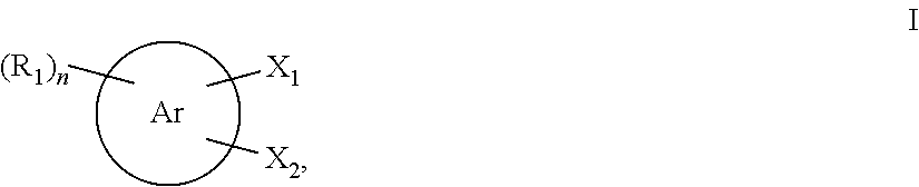
wherein
-
- Ar is a 5-20 membered aromatic moiety, optionally comprising one of more O, N, or S heteroatoms;
- X1 and X2 are independently —OH, —NHR′, —SH, or an anion thereof, X1 and X2 being positioned ortho to one another;
- R1 is independently at each occurrence H, C1-6 alkoxy, C1-6 alkyl, C1-6 alkenyl, C1-6 alkynyl, 5-6 membered aryl or heteroaryl, a boric acid or a salt thereof, carboxy acid or a salt thereof, C2-6 carboxylate, cyano, halo, hydroxyl, nitro, sulfonate, sulfonic acid or a salt thereof, phosphonate, phosphonic acid or a salt thereof, or a polyglycol;
- R′ is independently H or C1-3 alkyl;
- and m is +1, 0, −1, −2, −3, −4, or −5.

wherein
-
- X1 and X2 are independently —OH, —NHR′, —SH, or an anion thereof;
- R1 is independently at each occurrence H, C1-6 alkoxy, C1-6 alkyl, a boric acid or a salt thereof, a carboxy acid or a salt thereof, C2-6 carboxylate, cyano, halo, hydroxyl, nitro, sulfonate, a sulfonic acid or a salt thereof, phosphonate, phosphonic acid or a salt thereof, or a polyglycol;
- R′ is independently H or C1-3 alkyl; and
- n is 0-4.
-
- X1 and X2 are both OH or an anion thereof;
- R1 is independently H, C1-3 alkoxy, C1-3 alkyl, a boric acid or a salt thereof, carboxy acid or a salt thereof, C2-6 carboxylate, cyano, halo, hydroxyl, nitro, sulfonate, sulfonic acid or a salt thereof, phosphonate, phosphonic acid or a salt thereof, or a polyglycol; and
- n is 1.
-
- (a) a first chamber containing the first aqueous electrolyte and a second chamber containing the second aqueous electrolyte;
- (b) at least one electrolyte circulation loop in fluidic communication each electrolyte chamber, said at least one electrolyte circulation loop comprising storage tanks and piping for containing and transporting the electrolytes;
- (c) control hardware and software; and
- (d) an optional power conditioning unit.
-
- (a) reduce the first redox active metal-ligand coordination compound; or
- (b) oxidize the second redox active metal-ligand coordination compound; or
- (c) both (a) and (b).
-
- (a) oxidize the first redox active metal-ligand coordination compound; or
- (b) reduce the second redox active metal-ligand coordination compound; or
- (c) both (a) and (b).
| TABLE 1 |
| Mass spectroscopy data for selected compound* |
| Mass (m/z) | ||
| Calc'd/Obs'd | ||
| Ti(catecholate)3 2− | 186.0080/186.0 | ||
| Ti(pyrogallate)3 2− | 210.0038/210.0 | ||
| Ti(catecholate)2(pyrogallate)2− | 194.0055/194.0 | ||
| Ti(catecholate)2(ascorbate)2− | 219.0057/219.0 | ||
| Ti(catecholate)2(gluconate)2− | 229.0188/229.0 | ||
| Ti(catecholate)2(lactate)2− | 176.0055/176.0 | ||
| *Mass spectrometry data were obtained on an Agilent 6150B single quadrupole LC/MS in the negative ion mode with electrospray ionization (ESI). Aqueous solution samples of the metal ligand complex were diluted in methanol and introduced to the mass spectrometer ionizer by direct injection using a syringe pump. The reported m/z peaks in each case are for the dianions, z = −2. | |||
| Table 2A Exemplary electrochemical couples described herein |
| Solubility | Charge | ||||
| E1/2, V vs. | (Molar), | Density | |||
| Couple | RHE | pH | FIG. | 25° C. | (Ah/L) |
| Al(citrate)2(catecholate)2−/3− | 1.25 | 11.5 | 8 | 0.5 | 13.4 |
| Fe(catecholate)3 2−/3− | −0.50 | 11 | 10 | 1.5 | 40.2 |
| Ti(catecholate)3 2−/3− | −0.45 | 11 | 15 | 1.0 | 26.8 |
| Ti(pyrogallate)3 2−/3− | −0.55 | 9.8 | 9 | 1.6 | 42.9 |
| Ti(catecholate)2(pyrogallate)2−/3− | −0.50 | 11 | 11 | 1.5 | 40.2 |
| Ti(catecholate)2(ascorbate)2−/3− | −0.55 | 10 | 14 | 1.5 | 40.2 |
| Ti(catecholate)2(gluconate)2−/3− | −0.60 | 9 | 13 | 1.5 | 40.2 |
| Ti(catecholate)2(lactate)2−/3− | −0.49 | 9 | 12 | 1.5 | 40.2 |
| Ti(catecholate)(pyrogallate)(lactate)2−/3− | −0.70 | 8.5 | 16 | 1.5 | 40.2 |
| Ti(citrate)3 | −0.04 | 5 | 17 | 2.0 | 53.6 |
| Fe(CN)6 3−/4− | 1.18 | 11 | 18 | 1.5 | 40.2 |
| Cr(CN)6 3−/4− | −0.60 | 9 | 19 | 1.5 | 40.2 |
| Mn(CN)6 3−/4− | −0.60 | 9 | 20 | 1.5 | 40.2 |
| Table 2B Exemplary electrochemical couples described herein |
| Solubility | Charge | ||||
| E1/2, V vs. | (Molar), | Density | |||
| Couple | RHE | pH | FIG.* | 25° C. | (Ah/L) |
| TiIV/III(lactate)1 | −0.34 | 3.6 | N/S | 1.75 | 46.9 |
| TiIV/III(lactate)1 | −0.40 | 5.6 | 25 | 1.75 | 46.9 |
| TiIV/III(lactate)1 | −0.54 | 9 | 26 | 1.75 | 46.9 |
| TiIV/III(lactate)2 | −0.03 | 2 | 27 | 1.75 | 46.9 |
| TiIV/III(lactate)2 | −0.40 | 3.6 | 28 | 1.75 | 46.9 |
| TiIV/III(lactate)2 | −0.40 | 9 | 29 | 1.75 | 46.9 |
| TiIV/III(lactate)1(malate)2 | −0.40 | 9.9 | 30 | 1.5 | 40.2 |
| TiIV/III(malate)2(salicylate) | −0.48 | 10 | 31 | 1.5 | 40.2 |
| TiIV/III(lactate)2(glycinate) | −0.50 | 9.9 | 32 | 1.5 | 40.2 |
| TiIV/III(lactate)2(salicylate) | −0.48 | 10 | 33 | 1.5 | 40.2 |
| TiIV/III(salicylate)2(lactate) | −0.50 | 9.8 | 34 | 1.5 | 40.2 |
| TiIV/III(α-hydroxyacetate)2(salicylate) | −0.48 | 10 | 35 | 1.5 | 40.2 |
| TiIV/III(malate)2(salicylate) | −0.50 | 10 | N/S | 1.5 | 40.2 |
| TiIV/III(α-hydroxyacetate)2(lactate) | −0.50 | 10 | 36 | 1.5 | 40.2 |
| TiIV/III(lactate)2(α-hydroxyacetate) | −0.50 | 10 | N/S | 1.5 | 40.2 |
| TiIV/III(lactate)3 | −0.45 | 10 | N/S | 1.75 | 46.9 |
| TiIV/III(salicylate)3 | −0.25 | 8.6 | 23 | 0.5 | 13.4 |
| FeIII/II(salicylate)3 | −0.10 | 9.3 | 24 | 0.5 | 13.4 |
| FeIII/II(malate)3 | −0.30 | 9.2 | 37 | 1.0 | 26.8 |
| FeIII/II(α-hydroxyacetate)3 | −0.50 | 8.1 | 38 | 1.0 | 26.8 |
| FeIII/II(lactate)2(salicylate)1 | −0.39 | 8.7 | N/S | 1.0 | 26.8 |
| FeIII/II(lactate)2(glycinate)1 | +0.30 | 6.7 | N/S | 1.0 | 26.8 |
| FeIII/II(lactate)2 | +0.45 | 2.6 | 40 | 1.5 | 40.2 |
| FeIII/II(lactate)1 | +0.11 | 3.1 | 39 | 1.5 | 40.2 |
| Fe(CN)6 3−/4− | +1.18 | 11 | 18 | 1.5 | 40.2 |
| Al(citrate)2(catecholate)2−/3− | +1.25 | 11.5 | 8 | 0.5 | 13.4 |
| FeIII/II(H2O)6 | +0.77 | 0 | N/S | 2 | 53.6 |
| CeIV/III(H2O)x | +1.75 | 0 | N/S | 0.5 | 13.4 |
| *N/S = Not Shown | |||||
| Table 3A Calculated OCVs and theoretical energy density (Wh/L) for |
| various other electrolyte couple pairs calculated from data in Table 2. |
| Fe(CN)6 3−/4− | Al(cit)2(cat)2−/3− |
| Energy | Energy | |||
| OCV | Density | OCV | Density | |
| Couple | (V) | (Wh/L) | (V) | (Wh/L) |
| Mn(CN)6 3−/4− | 1.78 | 35.8 | 1.85 | 12.4 |
| Fe(catecholate)3 2−/3− | 1.68 | 33.8 | 1.75 | 11.7 |
| Ti(catecholate)3 2−/3− | 1.63 | 21.8 | 1.70 | 11.4 |
| Ti(pyrogallate)3 2−/3− | 1.73 | 34.8 | 1.80 | 12.1 |
| Ti(catecholate)2(pyrogallate)2−/3− | 1.68 | 33.8 | 1.75 | 11.7 |
| Ti(catecholate)2(ascorbate)2−/3− | 1.73 | 34.8 | 1.80 | 12.1 |
| Ti(catecholate)2(gluconate)2−/3− | 1.78 | 35.8 | 1.85 | 12.4 |
| Ti(catecholate)2(lactate)2−/3− | 1.67 | 33.6 | 1.74 | 11.7 |
| Ti(catecholate)(pyrogallate)- | 1.73 | 34.8 | 1.80 | 12.1 |
| (lactate)2−/3− | ||||
| Ti(citrate)3 | 1.22 | 24.5 | 1.29 | 8.6 |
| Table 3B Calculated OCVs and theoretical energy density (Wh/L) for |
| various electrolyte couple pairs calculated from data in Table 2. |
| Fe(CN)6 3−/4− | Al(cit)2(cat)2−/3− |
| Energy | Energy | |||
| OCV | Density | OCV | Density | |
| Couple | (V) | (Wh/L) | (V) | (Wh/L) |
| TiIV/III(lactate)1 | 1.60 | 34.9 | 1.67 | 25.2 |
| TiIV/III(lactate)2 | 1.46 | 31.8 | 1.53 | 23.1 |
| TiIV/III(lactate)3 | 1.57 | 34.2 | 1.64 | 24.7 |
| TiIV/III(salicylate)3 | 1.29 | 17.3 | 1.36 | 9.1 |
| TiIV/III(lactate)1(malate)2 | 1.51 | 30.4 | 1.58 | 21.2 |
| TiIV/III(malate)2(salicylate) | 1.60 | 32.2 | 1.67 | 22.4 |
| TiIV/III(lactate)2(glycinate) | 1.61 | 32.4 | 1.68 | 22.5 |
| TiIV/III(lactate)2(salicylate) | 1.60 | 32.2 | 1.67 | 22.4 |
| TiIV/III(salicylate)2(lactate) | 1.61 | 32.3 | 1.68 | 22.5 |
| TiIV/III(α- | 1.60 | 32.2 | 1.67 | 22.4 |
| hydroxyacetate)2(salicylate) | ||||
| TiIV/III(malate)2(sal) | 1.62 | 32.6 | 1.69 | 22.6 |
| TiIV/III(α-hydroxyacetate)2(lactate) | 1.62 | 32.6 | 1.69 | 22.6 |
| TiIV/III(lactate)2(α-hydroxyacetate) | 1.62 | 32.6 | 1.69 | 22.6 |
| FeIII/II(salicylate)3 | 1.18 | 15.8 | 1.25 | 8.4 |
| FeIII/II(malate)3 | 1.37 | 23.0 | 1.44 | 14.5 |
| FeIII/II(α-hydroxyacetate)3 | 1.51 | 25.3 | 1.58 | 15.9 |
| TABLE 4 |
| Calculated OCVs and theoretical energy density (Wh/L) for various |
| electrolyte couple pairs calculated from data in Table 2 in mildly acidic |
| solutions. |
| 2M FeIII/II, | 0.5M CeIV/III, | |||
| |
|
| Energy | Energy | |||||
| OCV | Density | OCV | Density | |||
| Couple | (V) | (Wh/L) | (V) | (Wh/L) | ||
| TiIV/III(lactate)1 | 1.32 | 33.2 | 2.30 | 34.7 | ||
| TiIV/III(lactate)2 | 0.92 | 23.1 | 1.90 | 28.6 | ||
Claims (23)


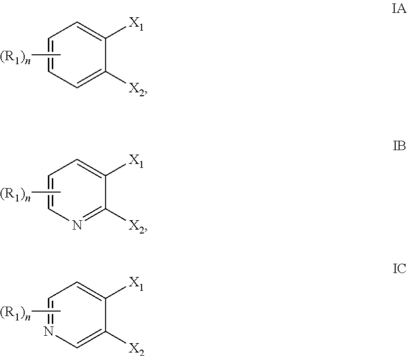
Priority Applications (61)
| Application Number | Priority Date | Filing Date | Title |
|---|---|---|---|
| US13/948,497 US9768463B2 (en) | 2012-07-27 | 2013-07-23 | Aqueous redox flow batteries comprising metal ligand coordination compounds |
| CN201710821249.2A CN107732272B (en) | 2012-07-27 | 2013-07-24 | Redox flow batteries comprising matched ionomer membranes |
| IN682DEN2015 IN2015DN00682A (en) | 2012-07-27 | 2013-07-24 | |
| AU2013293113A AU2013293113A1 (en) | 2012-07-27 | 2013-07-24 | Electrochemical systems featuring high open circuit potential |
| AU2013293109A AU2013293109A1 (en) | 2012-07-27 | 2013-07-24 | Redox flow batteries comprising matched ionomer membranes |
| BR112015001740A BR112015001740A2 (en) | 2012-07-27 | 2013-07-24 | ideal electrochemical membrane energy storage systems |
| MX2015001279A MX2015001279A (en) | 2012-07-27 | 2013-07-24 | Electrochemical systems featuring high open circuit potential. |
| US13/949,373 US9899694B2 (en) | 2012-07-27 | 2013-07-24 | Electrochemical energy storage systems and methods featuring high open circuit potential |
| IN674DEN2015 IN2015DN00674A (en) | 2012-07-27 | 2013-07-24 | |
| EP13823245.9A EP2878026A4 (en) | 2012-07-27 | 2013-07-24 | Optimal membrane electrochemical energy storage systems |
| US13/949,530 US9865893B2 (en) | 2012-07-27 | 2013-07-24 | Electrochemical energy storage systems and methods featuring optimal membrane systems |
| MX2015001281A MX2015001281A (en) | 2012-07-27 | 2013-07-24 | Optimal membrane electrochemical energy storage systems. |
| KR1020157005378A KR102158001B1 (en) | 2012-07-27 | 2013-07-24 | Electrochemical energy storage systems and methods featuring large negative half-cell potentials |
| JP2015524413A JP6400577B2 (en) | 2012-07-27 | 2013-07-24 | Optimal membrane electrochemical energy storage system |
| RU2015106767A RU2015106767A (en) | 2012-07-27 | 2013-07-24 | Redox flow-through batteries containing suitable ionomer membranes |
| CA2880193A CA2880193C (en) | 2012-07-27 | 2013-07-24 | Aqeous redox flow batteries comprising matched ionomer membranes |
| RU2015106738A RU2015106738A (en) | 2012-07-27 | 2013-07-24 | ELECTROCHEMICAL SYSTEMS DIFFERENT BY HIGH VOLTAGE OF OPEN CIRCUIT |
| PCT/US2013/051774 WO2014018593A1 (en) | 2012-07-27 | 2013-07-24 | Electrochemical systems featuring high open circuit potential |
| EP13823483.6A EP2878022B1 (en) | 2012-07-27 | 2013-07-24 | Redox flow batteries comprising matched ionomer membranes |
| PCT/US2013/051767 WO2014018589A1 (en) | 2012-07-27 | 2013-07-24 | Redox flow batteries comprising matched ionomer membranes |
| CN201380050681.6A CN105190971B (en) | 2012-07-27 | 2013-07-24 | Optimal membrane electrochemical energy-storage system |
| EP13823283.0A EP2878021B1 (en) | 2012-07-27 | 2013-07-24 | Electrochemical systems featuring high open circuit potential |
| KR1020157005376A KR102156522B1 (en) | 2012-07-27 | 2013-07-24 | Redox flow batteries comprising matched ionomer membranes |
| JP2015524407A JP6345661B2 (en) | 2012-07-27 | 2013-07-24 | Redox flow battery with compatible ionomer membrane |
| US13/949,486 US9559374B2 (en) | 2012-07-27 | 2013-07-24 | Electrochemical energy storage systems and methods featuring large negative half-cell potentials |
| BR112015001751A BR112015001751A2 (en) | 2012-07-27 | 2013-07-24 | electrochemical systems that have high open circuit potential |
| BR112015001738A BR112015001738A2 (en) | 2012-07-27 | 2013-07-24 | redox flow batteries comprising compatible ionomer membranes |
| BR112015001720A BR112015001720A2 (en) | 2012-07-27 | 2013-07-24 | electrochemical energy storage systems and methods that have large negative semicell potentials |
| JP2015524411A JP6308566B2 (en) | 2012-07-27 | 2013-07-24 | Electrochemical energy storage system and method characterized by large negative half-cell potential |
| MX2015001278A MX2015001278A (en) | 2012-07-27 | 2013-07-24 | Redox flow batteries comprising matched ionomer membranes. |
| US13/949,324 US9692077B2 (en) | 2012-07-27 | 2013-07-24 | Aqueous redox flow batteries comprising matched ionomer membranes |
| RU2015106675A RU2015106675A (en) | 2012-07-27 | 2013-07-24 | ELECTROCHEMICAL SYSTEMS AND METHODS FOR ENERGY ACCUMULATION CHARACTERIZED BY LARGE NEGATIVE HALF-POTENTIALS |
| JP2015524408A JP6356126B2 (en) | 2012-07-27 | 2013-07-24 | Electrochemical system characterized by high open circuit potential |
| EP19155139.9A EP3502057A1 (en) | 2012-07-27 | 2013-07-24 | Electrochemical energy storage systems and methods featuring optimal membrane systems |
| PCT/US2013/051802 WO2014018615A1 (en) | 2012-07-27 | 2013-07-24 | Optimal membrane electrochemical energy storage systems |
| AU2013295838A AU2013295838A1 (en) | 2012-07-27 | 2013-07-24 | Optimal membrane electrochemical energy storage systems |
| RU2015106676A RU2015106676A (en) | 2012-07-27 | 2013-07-24 | ELECTROCHEMICAL SYSTEMS FOR ENERGY ACCUMULATION WITH AN OPTIMAL MEMBRANE |
| IN672DEN2015 IN2015DN00672A (en) | 2012-07-27 | 2013-07-24 | |
| CN201380050783.8A CN104854731B (en) | 2012-07-27 | 2013-07-24 | It is characterized as the electrochemical energy storage system of high open circuit voltage |
| KR1020157005380A KR102149161B1 (en) | 2012-07-27 | 2013-07-24 | Optimal membrane electrochemical energy storage systems |
| KR1020157005379A KR102149159B1 (en) | 2012-07-27 | 2013-07-24 | Electrochemical systems featuring high open circuit potential |
| CN201380050848.9A CN104854732B (en) | 2012-07-27 | 2013-07-24 | It is characterized as the electrochemical energy storage system and method for big negative pole half-cell potential |
| PCT/US2013/051790 WO2014018605A1 (en) | 2012-07-27 | 2013-07-24 | Electrochemical energy storage systems and methods featuring large negative half-cell potentials |
| IN676DEN2015 IN2015DN00676A (en) | 2012-07-27 | 2013-07-24 | |
| CN201380050730.6A CN104854730B (en) | 2012-07-27 | 2013-07-24 | The redox flow batteries of ionomeric membrane comprising matching |
| SG11201500624UA SG11201500624UA (en) | 2012-07-27 | 2013-07-24 | Redox flow batteries comprising matched ionomer membranes |
| MX2015001280A MX2015001280A (en) | 2012-07-27 | 2013-07-24 | Electrochemical energy storage systems and methods featuring large negative half-cell potentials. |
| EP13822525.5A EP2878020B1 (en) | 2012-07-27 | 2013-07-24 | Electrochemical energy storage systems and methods featuring large negative half-cell potentials |
| AU2013295828A AU2013295828A1 (en) | 2012-07-27 | 2013-07-24 | Electrochemical energy storage systems and methods featuring large negative half-cell potentials |
| IL236905A IL236905A0 (en) | 2012-07-27 | 2015-01-25 | Redox flow batteries comprising matched ionomer membranes |
| IL236906A IL236906A0 (en) | 2012-07-27 | 2015-01-25 | Optimal membrane electrochemical energy storage systems |
| IL236904A IL236904A0 (en) | 2012-07-27 | 2015-01-25 | Electrochemical systems featuring high open circuit potential |
| IL236907A IL236907A0 (en) | 2012-07-27 | 2015-01-25 | Electrochemical energy storage systems and mehods featuring large negative half-cell potentials |
| PH12015500183A PH12015500183A1 (en) | 2012-07-27 | 2015-01-27 | Redox flow batteries comprising matched ionomer membranes |
| US15/164,827 US10651489B2 (en) | 2012-07-27 | 2016-05-25 | Electrochemical energy storage systems and methods featuring optimal membrane systems |
| US15/167,930 US9991544B2 (en) | 2012-07-27 | 2016-05-27 | Aqueous redox flow batteries comprising metal ligand coordination compounds |
| US15/167,927 US10014546B2 (en) | 2012-07-27 | 2016-05-27 | Aqueous redox flow batteries comprising metal ligand coordination compounds |
| US15/387,594 US10483581B2 (en) | 2012-07-27 | 2016-12-21 | Electrochemical energy storage systems and methods featuring large negative half-cell potentials |
| US15/682,728 US10707513B2 (en) | 2012-07-27 | 2017-08-22 | Aqueous redox flow batteries comprising metal ligand coordination compounds |
| JP2018097010A JP6668414B2 (en) | 2012-07-27 | 2018-05-21 | Redox flow battery containing compatible ionomer membrane |
| JP2018112707A JP6704953B2 (en) | 2012-07-27 | 2018-06-13 | Electrochemical system featuring high open circuit potential |
Applications Claiming Priority (6)
| Application Number | Priority Date | Filing Date | Title |
|---|---|---|---|
| US201261676473P | 2012-07-27 | 2012-07-27 | |
| US201261683260P | 2012-08-15 | 2012-08-15 | |
| US201261738546P | 2012-12-18 | 2012-12-18 | |
| US201261739145P | 2012-12-19 | 2012-12-19 | |
| US13/795,878 US8753761B2 (en) | 2012-07-27 | 2013-03-12 | Aqueous redox flow batteries comprising metal ligand coordination compounds |
| US13/948,497 US9768463B2 (en) | 2012-07-27 | 2013-07-23 | Aqueous redox flow batteries comprising metal ligand coordination compounds |
Related Parent Applications (1)
| Application Number | Title | Priority Date | Filing Date |
|---|---|---|---|
| US13/795,878 Continuation-In-Part US8753761B2 (en) | 2012-07-27 | 2013-03-12 | Aqueous redox flow batteries comprising metal ligand coordination compounds |
Related Child Applications (8)
| Application Number | Title | Priority Date | Filing Date |
|---|---|---|---|
| US13/796,004 Continuation-In-Part US8691413B2 (en) | 2012-07-27 | 2013-03-12 | Aqueous redox flow batteries featuring improved cell design characteristics |
| US13/949,486 Continuation-In-Part US9559374B2 (en) | 2012-07-27 | 2013-07-24 | Electrochemical energy storage systems and methods featuring large negative half-cell potentials |
| US13/949,324 Continuation-In-Part US9692077B2 (en) | 2012-07-27 | 2013-07-24 | Aqueous redox flow batteries comprising matched ionomer membranes |
| US13/949,373 Continuation-In-Part US9899694B2 (en) | 2012-07-27 | 2013-07-24 | Electrochemical energy storage systems and methods featuring high open circuit potential |
| US13/949,530 Continuation-In-Part US9865893B2 (en) | 2012-07-27 | 2013-07-24 | Electrochemical energy storage systems and methods featuring optimal membrane systems |
| US15/167,930 Continuation US9991544B2 (en) | 2012-07-27 | 2016-05-27 | Aqueous redox flow batteries comprising metal ligand coordination compounds |
| US15/167,927 Continuation US10014546B2 (en) | 2012-07-27 | 2016-05-27 | Aqueous redox flow batteries comprising metal ligand coordination compounds |
| US15/682,728 Division US10707513B2 (en) | 2012-07-27 | 2017-08-22 | Aqueous redox flow batteries comprising metal ligand coordination compounds |
Publications (2)
| Publication Number | Publication Date |
|---|---|
| US20140028260A1 US20140028260A1 (en) | 2014-01-30 |
| US9768463B2 true US9768463B2 (en) | 2017-09-19 |
Family
ID=49994237
Family Applications (4)
| Application Number | Title | Priority Date | Filing Date |
|---|---|---|---|
| US13/948,497 Active 2034-08-22 US9768463B2 (en) | 2012-07-27 | 2013-07-23 | Aqueous redox flow batteries comprising metal ligand coordination compounds |
| US15/167,930 Active US9991544B2 (en) | 2012-07-27 | 2016-05-27 | Aqueous redox flow batteries comprising metal ligand coordination compounds |
| US15/167,927 Active US10014546B2 (en) | 2012-07-27 | 2016-05-27 | Aqueous redox flow batteries comprising metal ligand coordination compounds |
| US15/682,728 Active 2033-07-07 US10707513B2 (en) | 2012-07-27 | 2017-08-22 | Aqueous redox flow batteries comprising metal ligand coordination compounds |
Family Applications After (3)
| Application Number | Title | Priority Date | Filing Date |
|---|---|---|---|
| US15/167,930 Active US9991544B2 (en) | 2012-07-27 | 2016-05-27 | Aqueous redox flow batteries comprising metal ligand coordination compounds |
| US15/167,927 Active US10014546B2 (en) | 2012-07-27 | 2016-05-27 | Aqueous redox flow batteries comprising metal ligand coordination compounds |
| US15/682,728 Active 2033-07-07 US10707513B2 (en) | 2012-07-27 | 2017-08-22 | Aqueous redox flow batteries comprising metal ligand coordination compounds |
Country Status (1)
| Country | Link |
|---|---|
| US (4) | US9768463B2 (en) |
Cited By (2)
| Publication number | Priority date | Publication date | Assignee | Title |
|---|---|---|---|---|
| US20170276583A1 (en) * | 2014-09-15 | 2017-09-28 | Stellenbosch University | A method and system for determining fluid density |
| US11217806B2 (en) | 2017-10-20 | 2022-01-04 | Lockheed Martin Energy, Llc | pH buffering region in a flow battery rebalancing cell |
Families Citing this family (50)
| Publication number | Priority date | Publication date | Assignee | Title |
|---|---|---|---|---|
| US9382274B2 (en) | 2012-07-27 | 2016-07-05 | Lockheed Martin Advanced Energy Storage, Llc | Aqueous redox flow batteries featuring improved cell design characteristics |
| US10164284B2 (en) | 2012-07-27 | 2018-12-25 | Lockheed Martin Energy, Llc | Aqueous redox flow batteries featuring improved cell design characteristics |
| US9899694B2 (en) | 2012-07-27 | 2018-02-20 | Lockheed Martin Advanced Energy Storage, Llc | Electrochemical energy storage systems and methods featuring high open circuit potential |
| US9559374B2 (en) | 2012-07-27 | 2017-01-31 | Lockheed Martin Advanced Energy Storage, Llc | Electrochemical energy storage systems and methods featuring large negative half-cell potentials |
| US9768463B2 (en) | 2012-07-27 | 2017-09-19 | Lockheed Martin Advanced Energy Storage, Llc | Aqueous redox flow batteries comprising metal ligand coordination compounds |
| US9865893B2 (en) | 2012-07-27 | 2018-01-09 | Lockheed Martin Advanced Energy Storage, Llc | Electrochemical energy storage systems and methods featuring optimal membrane systems |
| ES2865440T3 (en) | 2012-08-15 | 2021-10-15 | Lockheed Martin Energy Llc | High solubility iron hexacyanides |
| CN105684203B (en) | 2013-09-25 | 2019-07-26 | 洛克希德马丁能量有限公司 | Flow battery electrolyte balance strategy |
| WO2015054260A2 (en) * | 2013-10-07 | 2015-04-16 | Board Of Regents, The University Of Texas System | A redox flow battery that uses complexes of cobalt and iron with amino-alcohol ligands in alkaline electrolytes to store electrical energy |
| US9812883B2 (en) | 2014-02-18 | 2017-11-07 | Massachusetts Institute Of Technology | Materials for use with aqueous redox flow batteries and related methods and systems |
| EP3246720B1 (en) * | 2014-11-03 | 2019-09-18 | Dalian Rongke Power Co., Ltd. | Method and system for determining the state of charge of flow battery system |
| DK3224266T3 (en) | 2014-11-26 | 2021-04-26 | Lockheed Martin Energy Llc | Metal complexes of substituted catecholates and redox flow batteries containing these |
| US9899696B2 (en) * | 2015-01-21 | 2018-02-20 | Lockheed Martin Advanced Energy Storage, Llc | Solid buffer materials for electrolyte solutions and flow batteries utilizing same |
| US10253051B2 (en) * | 2015-03-16 | 2019-04-09 | Lockheed Martin Energy, Llc | Preparation of titanium catecholate complexes in aqueous solution using titanium tetrachloride or titanium oxychloride |
| WO2016154194A1 (en) | 2015-03-24 | 2016-09-29 | 3M Innovative Properties Company | Porous electrodes and electrochemical cells and liquid flow batteries therefrom |
| JP2018510473A (en) | 2015-03-24 | 2018-04-12 | スリーエム イノベイティブ プロパティズ カンパニー | Porous electrode, membrane electrode assembly, electrode assembly, electrochemical cell and liquid flow battery using the same |
| JP2018513527A (en) | 2015-03-24 | 2018-05-24 | スリーエム イノベイティブ プロパティズ カンパニー | Porous electrode and electrochemical cell and liquid flow battery therefrom |
| US20180053955A1 (en) | 2015-03-24 | 2018-02-22 | 3M Innovative Properties Company | Membrane Assemblies, Electrode Assemblies, Membrane-Electrode Assemblies and Electrochemical Cells and Liquid Flow Batteries Therefrom |
| US10411285B2 (en) * | 2015-04-14 | 2019-09-10 | Lockheed Martin Energy, Llc | Flow battery balancing cells having a bipolar membrane for simultaneous modification of a negative electrolyte solution and a positive electrolyte solution |
| JP2018533818A (en) * | 2015-10-30 | 2018-11-15 | マサチューセッツ インスティテュート オブ テクノロジー | Air Breathing Aqueous Sulfur Rechargeable Battery |
| US10644342B2 (en) * | 2016-03-03 | 2020-05-05 | Lockheed Martin Energy, Llc | Coordination complexes containing monosulfonated catecholate ligands and methods for producing the same |
| US10316047B2 (en) | 2016-03-03 | 2019-06-11 | Lockheed Martin Energy, Llc | Processes for forming coordination complexes containing monosulfonated catecholate ligands |
| JP2019512842A (en) | 2016-03-10 | 2019-05-16 | スリーエム イノベイティブ プロパティズ カンパニー | Electrode solution and electrochemical cell and battery using the same |
| WO2017160967A2 (en) | 2016-03-17 | 2017-09-21 | 3M Innovative Properties Company | Membrane assemblies, electrode assemblies, membrane-electrode assemblies and electrochemical cells and liquid flow batteries therefrom |
| JP2019508865A (en) | 2016-03-17 | 2019-03-28 | スリーエム イノベイティブ プロパティズ カンパニー | Electrode assembly, membrane electrode assembly, and electrochemical cell and liquid flow battery using the same |
| US20190051922A1 (en) | 2016-03-17 | 2019-02-14 | 3M Innovative Properties Company | Membrane assemblies, electrode assemblies, membrane-electrode assemblies and electrochemical cells and liquid flow batteries therefrom |
| US9938308B2 (en) | 2016-04-07 | 2018-04-10 | Lockheed Martin Energy, Llc | Coordination compounds having redox non-innocent ligands and flow batteries containing the same |
| KR101864710B1 (en) | 2016-06-28 | 2018-06-07 | 한국과학기술연구원 | Crown ether-inclusive electrolyte for redox flow batteries and method of manufacturing the same |
| US10934258B2 (en) * | 2016-07-25 | 2021-03-02 | Utah State University | Materials for use in an aqueous organic redox flow battery |
| US10377687B2 (en) * | 2016-07-26 | 2019-08-13 | Lockheed Martin Energy, Llc | Processes for forming titanium catechol complexes |
| US10343964B2 (en) | 2016-07-26 | 2019-07-09 | Lockheed Martin Energy, Llc | Processes for forming titanium catechol complexes |
| JP2019527920A (en) | 2016-08-11 | 2019-10-03 | スリーエム イノベイティブ プロパティズ カンパニー | Membrane electrode assembly and electrochemical cell and liquid flow battery made therefrom |
| US10707531B1 (en) | 2016-09-27 | 2020-07-07 | New Dominion Enterprises Inc. | All-inorganic solvents for electrolytes |
| US10065977B2 (en) | 2016-10-19 | 2018-09-04 | Lockheed Martin Advanced Energy Storage, Llc | Concerted processes for forming 1,2,4-trihydroxybenzene from hydroquinone |
| US10930937B2 (en) | 2016-11-23 | 2021-02-23 | Lockheed Martin Energy, Llc | Flow batteries incorporating active materials containing doubly bridged aromatic groups |
| US10497958B2 (en) | 2016-12-14 | 2019-12-03 | Lockheed Martin Energy, Llc | Coordinatively unsaturated titanium catecholate complexes and processes associated therewith |
| US10741864B2 (en) * | 2016-12-30 | 2020-08-11 | Lockheed Martin Energy, Llc | Aqueous methods for forming titanium catecholate complexes and associated compositions |
| US10320023B2 (en) | 2017-02-16 | 2019-06-11 | Lockheed Martin Energy, Llc | Neat methods for forming titanium catecholate complexes and associated compositions |
| KR101946485B1 (en) * | 2017-04-27 | 2019-02-11 | 한국에너지기술연구원 | Device for estimation of State-of-Charge for Zinc Flow Batteries and method estimation method using the same |
| US11177497B2 (en) * | 2018-03-12 | 2021-11-16 | Washington University | Redox flow battery |
| US20190322189A1 (en) * | 2018-04-18 | 2019-10-24 | Vionx Energy Corporation | Flow battery-based charging systems |
| US11705571B2 (en) | 2018-09-05 | 2023-07-18 | Nikolai M. Kocherginsky | Foil-based redox flow battery |
| WO2020065455A1 (en) | 2018-09-24 | 2020-04-02 | 3M Innovative Properties Company | Porous electrode, membrane-electrode assembly, liquid flow battery and method of making a porous electrode |
| WO2020191330A1 (en) * | 2019-03-20 | 2020-09-24 | The Regents Of The University Of Colorado, A Body Corporate | Electrochemical storage devices comprising chelated metals |
| EP3726633A1 (en) | 2019-04-16 | 2020-10-21 | Universität Innsbruck | Redox flow battery |
| US20200388857A1 (en) * | 2019-06-10 | 2020-12-10 | University Of Louisville Research Foundation, Inc. | Redox flow batteries employing diamond |
| WO2022173785A1 (en) * | 2021-02-11 | 2022-08-18 | University Of Washington | Aqueous redox flow batteries with redox-active solid additives |
| AU2022262366A1 (en) * | 2021-04-21 | 2023-12-07 | New Sky Energy Llc | Alkaline aqueous ferric iron salt solution electrolytes and batteries made therefrom |
| WO2023219648A1 (en) | 2022-05-09 | 2023-11-16 | Lockheed Martin Energy, Llc | Flow battery with a dynamic fluidic network |
| CN117317331A (en) * | 2023-11-28 | 2023-12-29 | 华中科技大学 | Positive electrode electrolyte of chromium chelate and flow battery |
Citations (159)
| Publication number | Priority date | Publication date | Assignee | Title |
|---|---|---|---|---|
| SU176574A1 (en) | И. Я. Кириченко, Р. П. Сидорова, Е. Ф. Рутман , Т. У. Ищенко | Method of producing potassium ferrocyanide | ||
| US2353782A (en) | 1942-05-02 | 1944-07-18 | Gen Chemical Corp | Electrolytic preparation of sodium ferricyanide |
| US2415792A (en) | 1945-09-19 | 1947-02-11 | American Cyanamid Co | Preparation of potassium ferricyanide |
| US3294588A (en) | 1962-04-19 | 1966-12-27 | Exxon Research Engineering Co | Method of operating fuel cell with electrolyte containing quinones or dyes |
| FR1533662A (en) | 1967-08-04 | 1968-07-19 | Ass Elect Ind | electric battery cell |
| US3573984A (en) | 1968-04-17 | 1971-04-06 | Macdermid Inc | Alkaline desmutting composition for ferrous metals |
| US3707449A (en) | 1970-04-09 | 1972-12-26 | Degussa | Process for the production of pure aqueous potassium as sodium hexacyanoferrate (iii) solution |
| GB1354886A (en) | 1970-06-29 | 1974-06-05 | Electrocell Ltd | Electrochemical fuel cell |
| US3876435A (en) | 1973-10-01 | 1975-04-08 | Amchem Prod | Chromate conversion coating solutions having chloride, sulfate, and nitrate anions |
| US3919000A (en) | 1973-06-15 | 1975-11-11 | Pennwalt Corp | Preanneal rinse process for inhibiting rust on steel strip |
| US3929506A (en) | 1973-05-18 | 1975-12-30 | Dow Chemical Co | Zinc-bromide secondary cell |
| US3985585A (en) | 1973-09-21 | 1976-10-12 | J. N. Tuttle, Inc. | Process for treating aluminum with ferricyanide compound |
| US3985517A (en) | 1975-08-20 | 1976-10-12 | Hydrocarbon Research, Inc. | Coal passivation process |
| US3985571A (en) | 1973-02-19 | 1976-10-12 | Deutsche Gold- Und Silber-Scheideanstalt Vormals Roessler | Process for the production of Berlin blue |
| US4046861A (en) | 1974-11-08 | 1977-09-06 | Deutsche Gold- Und Silber-Scheideanstalt Vormals Roessler | Process for the production of ferrocyanide blue |
| JPS52114934A (en) | 1976-03-17 | 1977-09-27 | Eco Control | Halogen complexed alcohol and nitrile |
| US4064324A (en) | 1976-04-07 | 1977-12-20 | Exxon Research & Engineering Co. | Metal-Halogenelectrochemical cell |
| US4069371A (en) | 1976-05-10 | 1978-01-17 | Gel, Inc. | Energy conversion |
| US4126529A (en) | 1977-08-05 | 1978-11-21 | Southern California Edison Company | Ferrous ion scrubbing of flue gas |
| US4133941A (en) | 1977-03-10 | 1979-01-09 | The United States Of America As Represented By The Administrator Of The National Aeronautics And Space Administration | Formulated plastic separators for soluble electrode cells |
| JPS5490538A (en) | 1977-12-19 | 1979-07-18 | Lockheed Missiles Space | Rechargeable battery cell |
| EP0013113A1 (en) | 1978-12-21 | 1980-07-09 | Allied Corporation | A process and apparatus for the production of electrical energy from the neutralization of acid and base in a bipolar membrane cell |
| US4233144A (en) | 1979-04-16 | 1980-11-11 | Technicon Instruments Corporation | Electrode for voltammetric immunoassay |
| US4362791A (en) * | 1980-06-17 | 1982-12-07 | Agency Of Industrial Science & Technology | Redox battery |
| US4378995A (en) | 1980-10-10 | 1983-04-05 | Degussa Aktiengesellschaft | Iron blue pigment, process for making the same and use |
| US4410606A (en) | 1982-04-21 | 1983-10-18 | Loutfy Raouf O | Low temperature thermally regenerative electrochemical system |
| US4436711A (en) | 1982-09-30 | 1984-03-13 | Shell Oil Company | Method of removing hydrogen sulfide from gases utilizing a polyvalent metal chelate solution and regenerating the solution in a fuel cell |
| US4436713A (en) | 1982-09-30 | 1984-03-13 | Shell Oil Company | Method of removing hydrogen sulfide from gases utilizing a polyvalent metal chelate of nitrilotriacetic acid and regenerating the solution in a fuel cell |
| US4436714A (en) | 1982-09-30 | 1984-03-13 | Shell Oil Company | Method of removing hydrogen sulfide from gases utilizing a polyvalent metal chelate of nitrilotriacetic acid and electrolytically regenerating the solution |
| US4436712A (en) | 1982-09-30 | 1984-03-13 | Shell Oil Company | Method of removing hydrogen sulfide from gases utilizing a polyvalent metal chelate of nitrilotriacetic acid and electrolytically regenerating the solution |
| US4443423A (en) | 1982-09-30 | 1984-04-17 | Shell Oil Company | Method of removing hydrogen sulfide from gases utilizing a polyvalent metal chelate solution and electrolytically regenerating the solution |
| US4443424A (en) | 1982-09-30 | 1984-04-17 | Shell Oil Company | Method of removing hydrogen sulfide from gases utilizing a polyvalent metal chelate solution and electrolytically regenerating the solution |
| US4468441A (en) | 1981-10-01 | 1984-08-28 | Rai Research Corp. | Separator membranes for redox-type electrochemical cells |
| US4485154A (en) | 1981-09-08 | 1984-11-27 | Institute Of Gas Technology | Electrically rechargeable anionically active reduction-oxidation electrical storage-supply system |
| US4520083A (en) | 1983-03-02 | 1985-05-28 | Standard Oil Company (Indiana) | Non-aqueous electrochemical cell and electrolyte |
| US4563403A (en) | 1981-07-24 | 1986-01-07 | Julian John D | Electrolyte for electro-chemical cells |
| US4592973A (en) | 1983-10-05 | 1986-06-03 | Castle Technology Corp. | Supported liquid membrane electrochemical separators |
| US4617244A (en) | 1985-06-24 | 1986-10-14 | Greene Roland M | Additive for electrolyte of lead-acid batteries |
| JPS6353860A (en) | 1986-08-22 | 1988-03-08 | Tokuyama Soda Co Ltd | Diaphragm fro redox flow cell |
| US4818646A (en) | 1985-10-03 | 1989-04-04 | Ricoh Company, Ltd. | Polypyrrole film and method of producing the same |
| US4952289A (en) | 1988-05-09 | 1990-08-28 | Aquanautics Corporation | Macrocyclic amine complexes for ligand extraction and generation |
| US4959135A (en) | 1987-02-25 | 1990-09-25 | Aquanautics Corporation | Polyalkylamine complexes for ligand extraction and generation |
| JPH03245472A (en) | 1990-02-22 | 1991-11-01 | Matsushita Electric Ind Co Ltd | Two-pack type battery |
| US5258109A (en) | 1991-03-29 | 1993-11-02 | Vaughan Daniel J | Electrodialytic conversion of complexes and salts of metal cations |
| US5264097A (en) | 1991-03-29 | 1993-11-23 | Vaughan Daniel J | Electrodialytic conversion of complexes and salts of metal cations |
| EP0595688A1 (en) | 1992-10-21 | 1994-05-04 | Nippon Telegraph And Telephone Corporation | Temperature difference storage battery |
| JPH06140082A (en) | 1992-10-21 | 1994-05-20 | Nippon Telegr & Teleph Corp <Ntt> | Temperature difference type storage battery |
| US5318865A (en) | 1991-06-06 | 1994-06-07 | Director-General, Agency Of Industrial Science And Technology | Redox battery |
| US5433934A (en) | 1991-08-13 | 1995-07-18 | The Dow Chemical Company | Method for simultaneous absorption of sulfur dioxide and nitric oxide from flue gas |
| US5472807A (en) | 1993-11-30 | 1995-12-05 | The United States Of America As Represented By The Secretary Of The Navy | Aluminum-ferricyanide battery |
| JPH08185868A (en) | 1994-12-28 | 1996-07-16 | Nippon Telegr & Teleph Corp <Ntt> | Electrode for oxidation reducing reaction battery |
| JPH08287938A (en) | 1995-02-16 | 1996-11-01 | Kashimakita Kyodo Hatsuden Kk | Redox battery |
| US5643670A (en) | 1993-07-29 | 1997-07-01 | The Research Foundation Of State University Of New York At Buffalo | Particulate carbon complex |
| US5656390A (en) | 1995-02-16 | 1997-08-12 | Kashima-Kita Electric Power Corporation | Redox battery |
| US5679239A (en) | 1995-03-27 | 1997-10-21 | Electrocatalytic, Inc. | Process and apparatus for generating bromine |
| EP0814527A2 (en) | 1996-06-19 | 1997-12-29 | Kashima-Kita Electric Power Corporation | A redox flow type battery |
| US5759711A (en) | 1996-02-19 | 1998-06-02 | Kashima-Kita Electric Power Corporation | Liquid-circulating battery |
| US5785841A (en) | 1995-05-04 | 1998-07-28 | Dravo Lime Company | Method of removing sulfur dioxide and nitrogen oxides from a gaseous stream |
| US5876581A (en) | 1981-10-02 | 1999-03-02 | Seiko Instruments Inc. | Film of iron (III) hexacyanoferrate (II) and process of synthesizing same |
| US5910366A (en) | 1994-06-14 | 1999-06-08 | The University Of Ottawa | Thin film composite membrane as battery separator |
| US6030517A (en) | 1995-04-06 | 2000-02-29 | Centre National De La Recherche Scientifique | Process for preparing a film of an oxide or a hydroxide of an element of groups IIB or IIIA of the periodic table, and the composite structures which include such a film |
| US6054230A (en) | 1994-12-07 | 2000-04-25 | Japan Gore-Tex, Inc. | Ion exchange and electrode assembly for an electrochemical cell |
| US6143443A (en) | 1993-11-17 | 2000-11-07 | Pinnacle Arb Limited | Stabilized electrolyte solutions, methods of preparation thereof and redox cells and batteries containing stabilized electrolyte solutions |
| CN1284208A (en) | 1998-01-28 | 2001-02-14 | 凯米科有限责任公司 | Rebox flow battery system and cell stack |
| US20020083643A1 (en) | 2000-01-07 | 2002-07-04 | Amendola Steven C. | Hydrogen generation catalyst |
| JP2002216833A (en) | 2001-01-19 | 2002-08-02 | Kansai Electric Power Co Inc:The | Redox cell |
| US6461772B1 (en) | 1998-12-14 | 2002-10-08 | Sumitomo Electric Industries, Ltd. | Battery diaphragm |
| US20020146618A1 (en) | 2001-02-04 | 2002-10-10 | Chemergy, Energy Technologies | Cathode formulations for super-iron batteries |
| US6485868B1 (en) | 1999-08-02 | 2002-11-26 | Central Glass Company, Limited | Electrolyte for electrochemical device |
| US20020177042A1 (en) | 1997-03-27 | 2002-11-28 | Steven Amendola | High energy density boride batteries |
| EP1290068A2 (en) | 2000-06-02 | 2003-03-12 | Sri International | Polymer membrane composition |
| US6555989B1 (en) | 2001-11-27 | 2003-04-29 | Ballard Power Systems Inc. | Efficient load-following power generating system |
| US6624328B1 (en) | 2002-12-17 | 2003-09-23 | 3M Innovative Properties Company | Preparation of perfluorinated vinyl ethers having a sulfonyl fluoride end-group |
| US20030228394A1 (en) | 2002-05-31 | 2003-12-11 | Zinpro Corporation | Novel chromium (III) alpha amino acid complexes |
| EP1411576A1 (en) | 2001-06-12 | 2004-04-21 | Sumitomo Electric Industries, Ltd. | Cell frame for redox flow cell and redox flow cell |
| US20040096746A1 (en) | 2000-09-27 | 2004-05-20 | Ulrich Wietelmann | Method for drying organic liquid electrolytes |
| WO2004095602A2 (en) | 2003-04-17 | 2004-11-04 | Eda, Inc. | Battery with bifunctional electrolyte |
| US20050098437A1 (en) | 2003-11-12 | 2005-05-12 | Proton Energy Systems, Inc. | Use of carbon coating in an electrochemical cell |
| US20050244707A1 (en) | 2002-04-23 | 2005-11-03 | Maria Skyllas-Kazacos | Metal halide redox flow battery |
| US20060063065A1 (en) | 2001-08-10 | 2006-03-23 | Clarke Robert L | Battery with bifunctional electrolyte |
| US7046418B2 (en) | 2003-10-08 | 2006-05-16 | Gentex Corporation | Reversible electrodeposition devices and associated electrochemical media |
| JP2006254682A (en) | 2005-02-09 | 2006-09-21 | Kansai Electric Power Co Inc:The | Power supply system including combination of solar cell and redox flow cell |
| WO2006135958A1 (en) | 2005-06-20 | 2006-12-28 | V-Fuel Pty Ltd | Improved perfluorinated membranes and improved electrolytes for redox cells and batteries |
| US7193764B2 (en) | 2003-10-08 | 2007-03-20 | Gentex Corporation | Reversible electrodeposition devices and associated electrochemical media |
| US7252905B2 (en) | 2001-08-10 | 2007-08-07 | Plurion Limited | Lanthanide batteries |
| US7265162B2 (en) | 2003-11-13 | 2007-09-04 | 3M Innovative Properties Company | Bromine, chlorine or iodine functional polymer electrolytes crosslinked by e-beam |
| WO2007101284A1 (en) | 2006-03-06 | 2007-09-13 | Funktionswerkstoffe Forschungs-Und Entwicklungs Gmbh | Redox flow battery and electrolyte solution for a eine redox flow battery |
| US20070275291A1 (en) | 2006-05-10 | 2007-11-29 | Horizon Fuel Cell Technologies Pte. Ltd | Novel membrane electrode assembly and its manufacturing process |
| EP1901379A1 (en) | 2005-07-01 | 2008-03-19 | Tokuyama Corporation | Separating membrane for fuel cell |
| US7348088B2 (en) | 2002-12-19 | 2008-03-25 | 3M Innovative Properties Company | Polymer electrolyte membrane |
| US20080274385A1 (en) * | 2005-03-12 | 2008-11-06 | Andrew Martin Creeth | Fuel Cells |
| US7463917B2 (en) | 2004-04-28 | 2008-12-09 | Medtronic, Inc. | Electrodes for sustained delivery of energy |
| JP2008305559A (en) | 2007-06-05 | 2008-12-18 | Sony Corp | Fuel cell and electronic equipment |
| US20090110998A1 (en) | 2006-03-30 | 2009-04-30 | Fujifilm Corporation | Solid electrolyte membrane, method and apparatus for producing the same, membrane electrode assembly and fuel cell |
| US20090130525A1 (en) | 2005-07-07 | 2009-05-21 | Fujifilm Corporation | Solid electrolyte multilayer membrane, method and apparatus for producing the same, membrane electrode assembly, and fuel cell |
| US7550231B2 (en) | 2006-10-12 | 2009-06-23 | Stauffer John E | Tin-zinc secondary battery |
| US7557164B2 (en) | 2003-08-19 | 2009-07-07 | E. I. Du Pont De Nemours And Company | Membranes of fluorinated ionomer blended with nonionomeric fluoropolymers for electrochemical cells |
| US20090208807A1 (en) | 2005-07-07 | 2009-08-20 | Fujifilm Corporation | Solid electrolyte membrane, method and apparatus for producing the same, membrane electrode assembly and fuel cell |
| US7625663B2 (en) | 2001-08-10 | 2009-12-01 | Plurion Limited Company | Cerium batteries |
| US20090308752A1 (en) | 2004-10-19 | 2009-12-17 | Evans Christine E | Electrochemical Pump |
| US20100003586A1 (en) | 2008-07-01 | 2010-01-07 | Deeya Energy, Inc. A California C-Corp | Redox flow cell |
| US7645540B2 (en) | 2003-08-08 | 2010-01-12 | Rovcal, Inc. | Separators for alkaline electrochemical cells |
| US20100059388A1 (en) | 2006-05-05 | 2010-03-11 | Aic Nevada, Inc. | Electrochemical Oxidation of Organic Matter |
| US7678728B2 (en) | 2006-10-16 | 2010-03-16 | Stc.Unm | Self supporting structurally engineered non-platinum electrocatalyst for oxygen reduction in fuel cells |
| US20100086823A1 (en) | 2007-03-09 | 2010-04-08 | Sumitomo Chemical Company Limited | Membrane-electrode assembly and fuel battery using the same |
| US7745056B2 (en) | 2005-12-02 | 2010-06-29 | Lg Chem, Ltd. | Electrolyte for lithium secondary battery comprising chelating agent and lithium secondary battery using the same |
| US7767777B2 (en) | 2005-09-12 | 2010-08-03 | Merck Patent Gmbh | Metal complexes |
| US20100239946A1 (en) | 2006-03-30 | 2010-09-23 | Fujifilm Corporation | Solid electrolyte membrane, method and apparatus for producing the same, membrane electrode assembly and fuel cell |
| EP2235781A1 (en) | 2008-01-23 | 2010-10-06 | Acal Energy Limited | Redox fuel cells |
| US7935366B2 (en) | 2005-01-10 | 2011-05-03 | Secretary, Department Of Atomic Energy | Calcium Potassium Ferrocyanide, a prophylactic mixture comprising this compound and the use thereof for decorporation of Radiocesium in subjects affected by nuclear radiation |
| US20110136016A1 (en) | 2009-12-04 | 2011-06-09 | Beijing Prudent Century Technology Co., Ltd. | Polymer blend proton exchange membrane and method for manufacturing the same |
| WO2011075135A1 (en) | 2009-12-18 | 2011-06-23 | United Technologies Corporation | Flow battery with interdigitated flow field |
| CN102142571A (en) | 2010-01-29 | 2011-08-03 | 三星电子株式会社 | Organic electrolyte solution and redox flow battery including the same |
| US20110189549A1 (en) | 2010-01-29 | 2011-08-04 | Samsung Electronics Co., Ltd. | Redox flow battery |
| US20110195283A1 (en) * | 2010-01-29 | 2011-08-11 | Samsung Electronics Co., Ltd. | Organic electrolyte solution and redox flow battery including the same |
| US7998335B2 (en) | 2005-06-13 | 2011-08-16 | Cabot Microelectronics Corporation | Controlled electrochemical polishing method |
| WO2011098781A1 (en) | 2010-02-11 | 2011-08-18 | Johnson Matthey Plc | Method of preparing a polymer and compositions therefor |
| US20110200890A1 (en) | 2010-02-17 | 2011-08-18 | Kocherginsky Nikolai M | Redox membrane-based flow fuel cell |
| US20110223450A1 (en) | 2008-07-07 | 2011-09-15 | Enervault Corporation | Cascade Redox Flow Battery Systems |
| WO2011111717A1 (en) | 2010-03-12 | 2011-09-15 | 住友電気工業株式会社 | Redox flow battery |
| CN102203984A (en) | 2008-11-04 | 2011-09-28 | 加州理工学院 | Hybrid electrochemical generator with a soluble anode |
| US20110244277A1 (en) | 2010-03-30 | 2011-10-06 | Applied Materials, Inc. | High performance flow battery |
| US20110244367A1 (en) | 2008-12-22 | 2011-10-06 | Tokuyama Corporation | Separation membrane for fuel cell, and method for production thereof |
| WO2011149624A1 (en) | 2010-05-24 | 2011-12-01 | Ecovoltz, Inc. | Secondary battery system |
| JP2012009448A (en) | 2010-03-12 | 2012-01-12 | Sumitomo Electric Ind Ltd | Redox flow battery |
| US20120052347A1 (en) | 2010-08-25 | 2012-03-01 | Applied Materials, Inc. | Flow battery systems |
| US8129554B2 (en) | 2005-08-18 | 2012-03-06 | Merck Patent Gmbh | Metal complexes |
| US20120077066A1 (en) | 2010-09-24 | 2012-03-29 | Jian Zhang | Water based biological and photochemical batteries |
| US20120077095A1 (en) | 2010-09-09 | 2012-03-29 | Roumi Farshid | Electrochemical Energy Storage Systems and Methods |
| JP2012079878A (en) | 2010-09-30 | 2012-04-19 | Shibaura Mechatronics Corp | Endpoint monitor and plasma processing method |
| US20120107661A1 (en) | 2010-11-03 | 2012-05-03 | Samsung Electronics Co., Ltd. | Redox flow battery |
| US20120135278A1 (en) | 2009-06-09 | 2012-05-31 | Tomohisa Yoshie | Redox flow battery |
| EP2463950A1 (en) | 2010-12-07 | 2012-06-13 | Samsung Electronics Co., Ltd. | Lithium air battery |
| WO2012075810A1 (en) | 2010-12-10 | 2012-06-14 | 中国科学院大连化学物理研究所 | Use of porous membrane and composite membrane thereof in redox flow energy storage battery |
| CN102544526A (en) | 2012-01-20 | 2012-07-04 | 石家庄学院 | Preparation method of graphite felt modified electrode and all vanadium flow battery |
| US20120171541A1 (en) | 2010-12-31 | 2012-07-05 | Samsung Electronics Co., Ltd. | Redox flow battery |
| US20120183868A1 (en) | 2009-10-27 | 2012-07-19 | Electricite De France | Electrochemical device having a solid alkaline ion-conducting electrolyte and an aqueous electrolyte |
| US20120196188A1 (en) | 2009-10-16 | 2012-08-02 | Dalian Institute Of Chemical Physics, Chinese Academy Of Sciences | Aromatic polymer ion exchange membranes, its composite membrance, and its application in acidic electrolyte flow battery |
| US20120202099A1 (en) * | 2011-02-08 | 2012-08-09 | United Technologies Corporation | Flow battery having a low resistance membrane |
| WO2012117543A1 (en) | 2011-03-02 | 2012-09-07 | 日新電機株式会社 | Power storage battery |
| US20120244406A1 (en) | 2011-03-25 | 2012-09-27 | Battelle Memorial Institute | Iron-Sulfide Redox Flow Batteries |
| US20120263990A1 (en) | 2011-04-18 | 2012-10-18 | Hee-Tak Kim | Separator for redox flow battery and redox flow battery |
| CN102790233A (en) | 2011-05-20 | 2012-11-21 | 罗臬 | Flow battery |
| WO2012162383A1 (en) | 2011-05-23 | 2012-11-29 | University Of Kentucky Research Foundation | Flow battery |
| US20130004819A1 (en) | 2011-06-28 | 2013-01-03 | Seoul National University R&Db Foundation | Electrolyte for redox flow battery and redox flow battery including the same |
| WO2013006427A1 (en) | 2011-07-01 | 2013-01-10 | Sun Catalytix Corporation | Methods and systems useful for solar energy storage |
| WO2013048603A1 (en) | 2011-09-27 | 2013-04-04 | Battelle Memorial Institute | Redox flow batteries having multiple electroactive elements |
| US20130157087A1 (en) * | 2011-12-20 | 2013-06-20 | Arun Pandy | Flow battery system with standby mode |
| US20130252062A1 (en) | 2012-03-20 | 2013-09-26 | Zinc Air, Inc. | Secondary redox flow battery and method of making same |
| US20140004403A1 (en) | 2012-06-15 | 2014-01-02 | University Of Delaware | Multiple-membrane multiple-electrolyte redox flow battery design |
| US20140030631A1 (en) | 2012-07-27 | 2014-01-30 | Sun Catalytix Corporation | Electrochemical Energy Storage Systems and Methods Featuring Optimal Membrane Systems |
| WO2014018495A2 (en) | 2012-07-27 | 2014-01-30 | Sun Catalytix Corporation | Aqueous redox flow batteries comprising metal ligand coordination compounds |
| WO2014018589A1 (en) | 2012-07-27 | 2014-01-30 | Sun Catalytix Corporation | Redox flow batteries comprising matched ionomer membranes |
| US20140028261A1 (en) | 2012-07-27 | 2014-01-30 | Sun Catalytic Corporation | Electrochemical Energy Storage Systems and Methods Featuring Large Negative Half-Cell Potentials |
| US20140051002A1 (en) | 2012-07-27 | 2014-02-20 | Sun Catalytix Corporation | Aqueous redox flow batteries comprising matched ionomer membranes |
| US20140051003A1 (en) | 2012-08-15 | 2014-02-20 | Sun Catalytix Corporation | High solubility iron hexacyanides |
| US20140080035A1 (en) | 2012-07-27 | 2014-03-20 | Sun Catalytix Corporation | Electrochemical Energy Storage Systems and Methods Featuring High Open Circuit Potential |
| US8691413B2 (en) | 2012-07-27 | 2014-04-08 | Sun Catalytix Corporation | Aqueous redox flow batteries featuring improved cell design characteristics |
| US20140138576A1 (en) | 2012-07-27 | 2014-05-22 | Sun Catalytix Corporation | Aqueous redox flow batteries featuring improved cell design characteristics |
Family Cites Families (42)
| Publication number | Priority date | Publication date | Assignee | Title |
|---|---|---|---|---|
| US1279295A (en) | 1918-01-05 | 1918-09-17 | Barrett Co | Sulfonation of hydrocarbons and hydrocarbon derivatives. |
| ZA672362B (en) | 1965-08-04 | |||
| US3425796A (en) | 1967-05-15 | 1969-02-04 | Dow Chemical Co | Preparation of metal oxychlorides |
| US3772379A (en) | 1971-10-28 | 1973-11-13 | Eastman Kodak Co | Preparation of dialkali dihydroxybenzene disulfonates |
| JPS5518688B2 (en) | 1972-12-02 | 1980-05-21 | ||
| JPS4930330A (en) | 1973-03-23 | 1974-03-18 | ||
| JPS547198A (en) | 1977-06-17 | 1979-01-19 | Matsushita Electric Ind Co Ltd | Organic semiconductor |
| US4680308A (en) | 1985-12-26 | 1987-07-14 | Andrulis Research Corporation | Stable soluble 1,2-diaminocyclohexane platinum complexes |
| US4880758A (en) | 1987-08-24 | 1989-11-14 | The Dow Chemical Company | Preparation of ABO3 compounds from mixed metal aromatic coordination complexes |
| JPH01102042A (en) | 1987-10-16 | 1989-04-19 | Sanko Kaihatsu Kagaku Kenkyusho:Kk | Production of p-benzoquinone |
| US5084533A (en) | 1988-07-19 | 1992-01-28 | Hoechst Celanese Corporation | Neat (solventless) hydrogenation of 4-acetoxyacetophenone in the production of 4-acetoxystyrene and its polymers and hydrolysis products |
| US5122461A (en) | 1990-11-19 | 1992-06-16 | Industrial Technology Research Institute | Preparation of pyrocatecholic compounds |
| US7223833B1 (en) | 1991-05-24 | 2007-05-29 | Isis Pharmaceuticals, Inc. | Peptide nucleic acid conjugates |
| US5302481A (en) | 1993-06-07 | 1994-04-12 | Xerox Corporation | Toner compositions with negative charge enhancing complexes |
| WO1996035239A1 (en) | 1995-05-03 | 1996-11-07 | Unisearch Limited | High energy density vanadium electrolyte solutions, methods of preparation thereof and all-vanadium redox cells and batteries containing high energy vanadium electrolyte solutions |
| WO1997017354A1 (en) | 1995-11-06 | 1997-05-15 | Borealis A/S | Organometallic complexes having oxobenzoyl ligands |
| KR100277164B1 (en) | 1998-07-16 | 2001-01-15 | 장인순 | A preparing method for crystalline micropowder of Titania from aqueous Titanium(Ⅳ) chloride by homogeneous precipitation process at low temperature |
| JP4843832B2 (en) | 2000-05-26 | 2011-12-21 | 三菱化学株式会社 | Non-aqueous electrolyte and secondary battery using the same |
| US6585951B1 (en) | 2000-10-30 | 2003-07-01 | Idaho Research Foundation, Inc. | Methods for manufacturing dielectric powders |
| ATE327243T1 (en) * | 2002-07-17 | 2006-06-15 | Exxonmobil Chem Patents Inc | LATE TRANSITION METAL CATALYSTS FOR OLEFIN POLYMERIZATION AND OLIGOMERIZATION |
| US8779175B2 (en) | 2004-10-25 | 2014-07-15 | Synthonics, Inc. | Coordination complexes, pharmaceutical solutions comprising coordination complexes, and methods of treating patients |
| JP4988737B2 (en) | 2006-07-13 | 2012-08-01 | 東海旅客鉄道株式会社 | Coating liquid, titanium oxide thin film formed using coating liquid, and method for forming the same |
| KR20110087273A (en) | 2008-09-29 | 2011-08-02 | 아커민 인코퍼레이티드 | Process for accelerated capture of carbon dioxide |
| CN101877412A (en) | 2009-04-30 | 2010-11-03 | 中国人民解放军63971部队 | Organic single flow battery |
| WO2011022588A1 (en) | 2009-08-21 | 2011-02-24 | Draths Corporation | Sulfonation of polyhydroxyaromatics |
| CN103339762B (en) | 2011-01-13 | 2016-03-30 | 伊莫基动力系统公司 | Flow cell stack |
| WO2013012391A1 (en) | 2011-07-21 | 2013-01-24 | National University Of Singapore | A redox flow battery system |
| US9300000B2 (en) | 2012-02-28 | 2016-03-29 | Uchicago Argonne, Llc | Organic non-aqueous cation-based redox flow batteries |
| JP5798954B2 (en) | 2012-03-08 | 2015-10-21 | 富士フイルム株式会社 | Non-aqueous secondary battery electrolyte and secondary battery |
| US10164284B2 (en) | 2012-07-27 | 2018-12-25 | Lockheed Martin Energy, Llc | Aqueous redox flow batteries featuring improved cell design characteristics |
| US9768463B2 (en) | 2012-07-27 | 2017-09-19 | Lockheed Martin Advanced Energy Storage, Llc | Aqueous redox flow batteries comprising metal ligand coordination compounds |
| KR102038619B1 (en) | 2013-01-08 | 2019-10-30 | 삼성전자주식회사 | Redox flow battery |
| US20140239906A1 (en) | 2013-02-28 | 2014-08-28 | Sandia Corporation | Redox-active ligand-based transition metal complex flow batteries |
| KR101503879B1 (en) | 2013-05-24 | 2015-03-20 | 한국과학기술연구원 | Magnesium hybrid battery and its fabrication method |
| WO2015069439A1 (en) | 2013-11-06 | 2015-05-14 | The Research Foundation For The State University Of New York | Extended life energy storage systems and methods of manufacturing thereof |
| US9812883B2 (en) | 2014-02-18 | 2017-11-07 | Massachusetts Institute Of Technology | Materials for use with aqueous redox flow batteries and related methods and systems |
| US10153510B2 (en) | 2014-06-23 | 2018-12-11 | University Of Kentucky Research Foundation | Non-aqueous redox flow batteries including 3,7-perfluoroalkylated phenothiazine derivatives |
| EP3179870B1 (en) | 2014-08-13 | 2023-10-04 | Akeso Biomedical Inc. | Antimicrobial compounds and compositions, and uses thereof |
| DK3224266T3 (en) | 2014-11-26 | 2021-04-26 | Lockheed Martin Energy Llc | Metal complexes of substituted catecholates and redox flow batteries containing these |
| CN104593779B (en) | 2015-01-21 | 2018-02-16 | 北京科技大学 | A kind of preparation method of the intelligent corrosion inhibiter of low pH controlled releases |
| US10253051B2 (en) | 2015-03-16 | 2019-04-09 | Lockheed Martin Energy, Llc | Preparation of titanium catecholate complexes in aqueous solution using titanium tetrachloride or titanium oxychloride |
| US9409842B1 (en) | 2015-04-13 | 2016-08-09 | Cristal Inorganic Chemicals Switzerland Ltd | Method for producing redox-active Ti(IV) coordination compounds |
-
2013
- 2013-07-23 US US13/948,497 patent/US9768463B2/en active Active
-
2016
- 2016-05-27 US US15/167,930 patent/US9991544B2/en active Active
- 2016-05-27 US US15/167,927 patent/US10014546B2/en active Active
-
2017
- 2017-08-22 US US15/682,728 patent/US10707513B2/en active Active
Patent Citations (174)
| Publication number | Priority date | Publication date | Assignee | Title |
|---|---|---|---|---|
| SU176574A1 (en) | И. Я. Кириченко, Р. П. Сидорова, Е. Ф. Рутман , Т. У. Ищенко | Method of producing potassium ferrocyanide | ||
| US2353782A (en) | 1942-05-02 | 1944-07-18 | Gen Chemical Corp | Electrolytic preparation of sodium ferricyanide |
| US2415792A (en) | 1945-09-19 | 1947-02-11 | American Cyanamid Co | Preparation of potassium ferricyanide |
| US3294588A (en) | 1962-04-19 | 1966-12-27 | Exxon Research Engineering Co | Method of operating fuel cell with electrolyte containing quinones or dyes |
| FR1533662A (en) | 1967-08-04 | 1968-07-19 | Ass Elect Ind | electric battery cell |
| US3573984A (en) | 1968-04-17 | 1971-04-06 | Macdermid Inc | Alkaline desmutting composition for ferrous metals |
| US3707449A (en) | 1970-04-09 | 1972-12-26 | Degussa | Process for the production of pure aqueous potassium as sodium hexacyanoferrate (iii) solution |
| GB1354886A (en) | 1970-06-29 | 1974-06-05 | Electrocell Ltd | Electrochemical fuel cell |
| US3985571A (en) | 1973-02-19 | 1976-10-12 | Deutsche Gold- Und Silber-Scheideanstalt Vormals Roessler | Process for the production of Berlin blue |
| US3929506A (en) | 1973-05-18 | 1975-12-30 | Dow Chemical Co | Zinc-bromide secondary cell |
| US3919000A (en) | 1973-06-15 | 1975-11-11 | Pennwalt Corp | Preanneal rinse process for inhibiting rust on steel strip |
| US3985585A (en) | 1973-09-21 | 1976-10-12 | J. N. Tuttle, Inc. | Process for treating aluminum with ferricyanide compound |
| US3876435A (en) | 1973-10-01 | 1975-04-08 | Amchem Prod | Chromate conversion coating solutions having chloride, sulfate, and nitrate anions |
| US4046861A (en) | 1974-11-08 | 1977-09-06 | Deutsche Gold- Und Silber-Scheideanstalt Vormals Roessler | Process for the production of ferrocyanide blue |
| US3985517A (en) | 1975-08-20 | 1976-10-12 | Hydrocarbon Research, Inc. | Coal passivation process |
| JPS52114934A (en) | 1976-03-17 | 1977-09-27 | Eco Control | Halogen complexed alcohol and nitrile |
| US4064324A (en) | 1976-04-07 | 1977-12-20 | Exxon Research & Engineering Co. | Metal-Halogenelectrochemical cell |
| US4069371A (en) | 1976-05-10 | 1978-01-17 | Gel, Inc. | Energy conversion |
| US4133941A (en) | 1977-03-10 | 1979-01-09 | The United States Of America As Represented By The Administrator Of The National Aeronautics And Space Administration | Formulated plastic separators for soluble electrode cells |
| US4126529A (en) | 1977-08-05 | 1978-11-21 | Southern California Edison Company | Ferrous ion scrubbing of flue gas |
| JPS5490538A (en) | 1977-12-19 | 1979-07-18 | Lockheed Missiles Space | Rechargeable battery cell |
| US4180623A (en) | 1977-12-19 | 1979-12-25 | Lockheed Missiles & Space Company, Inc. | Electrically rechargeable battery |
| EP0013113A1 (en) | 1978-12-21 | 1980-07-09 | Allied Corporation | A process and apparatus for the production of electrical energy from the neutralization of acid and base in a bipolar membrane cell |
| JPS55113274A (en) | 1978-12-21 | 1980-09-01 | Allied Chem | Method of and device for generating electric energy from neutralization of acid and base in bipolar film tank |
| US4233144A (en) | 1979-04-16 | 1980-11-11 | Technicon Instruments Corporation | Electrode for voltammetric immunoassay |
| US4362791A (en) * | 1980-06-17 | 1982-12-07 | Agency Of Industrial Science & Technology | Redox battery |
| US4378995A (en) | 1980-10-10 | 1983-04-05 | Degussa Aktiengesellschaft | Iron blue pigment, process for making the same and use |
| US4563403A (en) | 1981-07-24 | 1986-01-07 | Julian John D | Electrolyte for electro-chemical cells |
| US4485154A (en) | 1981-09-08 | 1984-11-27 | Institute Of Gas Technology | Electrically rechargeable anionically active reduction-oxidation electrical storage-supply system |
| US4468441A (en) | 1981-10-01 | 1984-08-28 | Rai Research Corp. | Separator membranes for redox-type electrochemical cells |
| US5876581A (en) | 1981-10-02 | 1999-03-02 | Seiko Instruments Inc. | Film of iron (III) hexacyanoferrate (II) and process of synthesizing same |
| US4410606A (en) | 1982-04-21 | 1983-10-18 | Loutfy Raouf O | Low temperature thermally regenerative electrochemical system |
| US4436712A (en) | 1982-09-30 | 1984-03-13 | Shell Oil Company | Method of removing hydrogen sulfide from gases utilizing a polyvalent metal chelate of nitrilotriacetic acid and electrolytically regenerating the solution |
| US4443424A (en) | 1982-09-30 | 1984-04-17 | Shell Oil Company | Method of removing hydrogen sulfide from gases utilizing a polyvalent metal chelate solution and electrolytically regenerating the solution |
| US4443423A (en) | 1982-09-30 | 1984-04-17 | Shell Oil Company | Method of removing hydrogen sulfide from gases utilizing a polyvalent metal chelate solution and electrolytically regenerating the solution |
| US4436714A (en) | 1982-09-30 | 1984-03-13 | Shell Oil Company | Method of removing hydrogen sulfide from gases utilizing a polyvalent metal chelate of nitrilotriacetic acid and electrolytically regenerating the solution |
| US4436713A (en) | 1982-09-30 | 1984-03-13 | Shell Oil Company | Method of removing hydrogen sulfide from gases utilizing a polyvalent metal chelate of nitrilotriacetic acid and regenerating the solution in a fuel cell |
| US4436711A (en) | 1982-09-30 | 1984-03-13 | Shell Oil Company | Method of removing hydrogen sulfide from gases utilizing a polyvalent metal chelate solution and regenerating the solution in a fuel cell |
| US4520083A (en) | 1983-03-02 | 1985-05-28 | Standard Oil Company (Indiana) | Non-aqueous electrochemical cell and electrolyte |
| US4592973A (en) | 1983-10-05 | 1986-06-03 | Castle Technology Corp. | Supported liquid membrane electrochemical separators |
| US4617244A (en) | 1985-06-24 | 1986-10-14 | Greene Roland M | Additive for electrolyte of lead-acid batteries |
| US4818646A (en) | 1985-10-03 | 1989-04-04 | Ricoh Company, Ltd. | Polypyrrole film and method of producing the same |
| JPS6353860A (en) | 1986-08-22 | 1988-03-08 | Tokuyama Soda Co Ltd | Diaphragm fro redox flow cell |
| US4959135A (en) | 1987-02-25 | 1990-09-25 | Aquanautics Corporation | Polyalkylamine complexes for ligand extraction and generation |
| US4952289A (en) | 1988-05-09 | 1990-08-28 | Aquanautics Corporation | Macrocyclic amine complexes for ligand extraction and generation |
| JPH03245472A (en) | 1990-02-22 | 1991-11-01 | Matsushita Electric Ind Co Ltd | Two-pack type battery |
| US5258109A (en) | 1991-03-29 | 1993-11-02 | Vaughan Daniel J | Electrodialytic conversion of complexes and salts of metal cations |
| US5264097A (en) | 1991-03-29 | 1993-11-23 | Vaughan Daniel J | Electrodialytic conversion of complexes and salts of metal cations |
| US5318865A (en) | 1991-06-06 | 1994-06-07 | Director-General, Agency Of Industrial Science And Technology | Redox battery |
| US5433934A (en) | 1991-08-13 | 1995-07-18 | The Dow Chemical Company | Method for simultaneous absorption of sulfur dioxide and nitric oxide from flue gas |
| US5310608A (en) | 1992-10-21 | 1994-05-10 | Nippon Telegraph And Telephone Corporation | Temperature difference storage battery |
| EP0595688A1 (en) | 1992-10-21 | 1994-05-04 | Nippon Telegraph And Telephone Corporation | Temperature difference storage battery |
| JPH06140082A (en) | 1992-10-21 | 1994-05-20 | Nippon Telegr & Teleph Corp <Ntt> | Temperature difference type storage battery |
| US5643670A (en) | 1993-07-29 | 1997-07-01 | The Research Foundation Of State University Of New York At Buffalo | Particulate carbon complex |
| US6143443A (en) | 1993-11-17 | 2000-11-07 | Pinnacle Arb Limited | Stabilized electrolyte solutions, methods of preparation thereof and redox cells and batteries containing stabilized electrolyte solutions |
| US5472807A (en) | 1993-11-30 | 1995-12-05 | The United States Of America As Represented By The Secretary Of The Navy | Aluminum-ferricyanide battery |
| US5910366A (en) | 1994-06-14 | 1999-06-08 | The University Of Ottawa | Thin film composite membrane as battery separator |
| US6054230A (en) | 1994-12-07 | 2000-04-25 | Japan Gore-Tex, Inc. | Ion exchange and electrode assembly for an electrochemical cell |
| JPH08185868A (en) | 1994-12-28 | 1996-07-16 | Nippon Telegr & Teleph Corp <Ntt> | Electrode for oxidation reducing reaction battery |
| JPH08287938A (en) | 1995-02-16 | 1996-11-01 | Kashimakita Kyodo Hatsuden Kk | Redox battery |
| US5656390A (en) | 1995-02-16 | 1997-08-12 | Kashima-Kita Electric Power Corporation | Redox battery |
| US5679239A (en) | 1995-03-27 | 1997-10-21 | Electrocatalytic, Inc. | Process and apparatus for generating bromine |
| US6030517A (en) | 1995-04-06 | 2000-02-29 | Centre National De La Recherche Scientifique | Process for preparing a film of an oxide or a hydroxide of an element of groups IIB or IIIA of the periodic table, and the composite structures which include such a film |
| US5785841A (en) | 1995-05-04 | 1998-07-28 | Dravo Lime Company | Method of removing sulfur dioxide and nitrogen oxides from a gaseous stream |
| US5759711A (en) | 1996-02-19 | 1998-06-02 | Kashima-Kita Electric Power Corporation | Liquid-circulating battery |
| EP0814527A2 (en) | 1996-06-19 | 1997-12-29 | Kashima-Kita Electric Power Corporation | A redox flow type battery |
| US20020177042A1 (en) | 1997-03-27 | 2002-11-28 | Steven Amendola | High energy density boride batteries |
| CN1284208A (en) | 1998-01-28 | 2001-02-14 | 凯米科有限责任公司 | Rebox flow battery system and cell stack |
| US6475661B1 (en) | 1998-01-28 | 2002-11-05 | Squirrel Holdings Ltd | Redox flow battery system and cell stack |
| US6461772B1 (en) | 1998-12-14 | 2002-10-08 | Sumitomo Electric Industries, Ltd. | Battery diaphragm |
| US6485868B1 (en) | 1999-08-02 | 2002-11-26 | Central Glass Company, Limited | Electrolyte for electrochemical device |
| US20020083643A1 (en) | 2000-01-07 | 2002-07-04 | Amendola Steven C. | Hydrogen generation catalyst |
| EP1290068A2 (en) | 2000-06-02 | 2003-03-12 | Sri International | Polymer membrane composition |
| US20040096746A1 (en) | 2000-09-27 | 2004-05-20 | Ulrich Wietelmann | Method for drying organic liquid electrolytes |
| JP2002216833A (en) | 2001-01-19 | 2002-08-02 | Kansai Electric Power Co Inc:The | Redox cell |
| US20020146618A1 (en) | 2001-02-04 | 2002-10-10 | Chemergy, Energy Technologies | Cathode formulations for super-iron batteries |
| EP1411576A1 (en) | 2001-06-12 | 2004-04-21 | Sumitomo Electric Industries, Ltd. | Cell frame for redox flow cell and redox flow cell |
| US7252905B2 (en) | 2001-08-10 | 2007-08-07 | Plurion Limited | Lanthanide batteries |
| US7625663B2 (en) | 2001-08-10 | 2009-12-01 | Plurion Limited Company | Cerium batteries |
| US20060063065A1 (en) | 2001-08-10 | 2006-03-23 | Clarke Robert L | Battery with bifunctional electrolyte |
| US6555989B1 (en) | 2001-11-27 | 2003-04-29 | Ballard Power Systems Inc. | Efficient load-following power generating system |
| US20050244707A1 (en) | 2002-04-23 | 2005-11-03 | Maria Skyllas-Kazacos | Metal halide redox flow battery |
| US20030228394A1 (en) | 2002-05-31 | 2003-12-11 | Zinpro Corporation | Novel chromium (III) alpha amino acid complexes |
| US6624328B1 (en) | 2002-12-17 | 2003-09-23 | 3M Innovative Properties Company | Preparation of perfluorinated vinyl ethers having a sulfonyl fluoride end-group |
| US7348088B2 (en) | 2002-12-19 | 2008-03-25 | 3M Innovative Properties Company | Polymer electrolyte membrane |
| WO2004095602A2 (en) | 2003-04-17 | 2004-11-04 | Eda, Inc. | Battery with bifunctional electrolyte |
| US7645540B2 (en) | 2003-08-08 | 2010-01-12 | Rovcal, Inc. | Separators for alkaline electrochemical cells |
| US7931981B2 (en) | 2003-08-08 | 2011-04-26 | Rovcal Inc. | Separators for alkaline electrochemical cells |
| US7557164B2 (en) | 2003-08-19 | 2009-07-07 | E. I. Du Pont De Nemours And Company | Membranes of fluorinated ionomer blended with nonionomeric fluoropolymers for electrochemical cells |
| US7046418B2 (en) | 2003-10-08 | 2006-05-16 | Gentex Corporation | Reversible electrodeposition devices and associated electrochemical media |
| US7508568B2 (en) | 2003-10-08 | 2009-03-24 | Gentex Corporation | Reversible electrodeposition devices and associated electrochemical media |
| US7193764B2 (en) | 2003-10-08 | 2007-03-20 | Gentex Corporation | Reversible electrodeposition devices and associated electrochemical media |
| US20050098437A1 (en) | 2003-11-12 | 2005-05-12 | Proton Energy Systems, Inc. | Use of carbon coating in an electrochemical cell |
| US7265162B2 (en) | 2003-11-13 | 2007-09-04 | 3M Innovative Properties Company | Bromine, chlorine or iodine functional polymer electrolytes crosslinked by e-beam |
| US7463917B2 (en) | 2004-04-28 | 2008-12-09 | Medtronic, Inc. | Electrodes for sustained delivery of energy |
| US20090308752A1 (en) | 2004-10-19 | 2009-12-17 | Evans Christine E | Electrochemical Pump |
| US8187441B2 (en) | 2004-10-19 | 2012-05-29 | Evans Christine E | Electrochemical pump |
| US7935366B2 (en) | 2005-01-10 | 2011-05-03 | Secretary, Department Of Atomic Energy | Calcium Potassium Ferrocyanide, a prophylactic mixture comprising this compound and the use thereof for decorporation of Radiocesium in subjects affected by nuclear radiation |
| JP2006254682A (en) | 2005-02-09 | 2006-09-21 | Kansai Electric Power Co Inc:The | Power supply system including combination of solar cell and redox flow cell |
| US20080274385A1 (en) * | 2005-03-12 | 2008-11-06 | Andrew Martin Creeth | Fuel Cells |
| US7998335B2 (en) | 2005-06-13 | 2011-08-16 | Cabot Microelectronics Corporation | Controlled electrochemical polishing method |
| WO2006135958A1 (en) | 2005-06-20 | 2006-12-28 | V-Fuel Pty Ltd | Improved perfluorinated membranes and improved electrolytes for redox cells and batteries |
| US20080292964A1 (en) | 2005-06-20 | 2008-11-27 | George Christopher Kazacos | Perfluorinated Membranes and Improved Electrolytes for Redox Cells and Batteries |
| EP1901379A1 (en) | 2005-07-01 | 2008-03-19 | Tokuyama Corporation | Separating membrane for fuel cell |
| US20090130525A1 (en) | 2005-07-07 | 2009-05-21 | Fujifilm Corporation | Solid electrolyte multilayer membrane, method and apparatus for producing the same, membrane electrode assembly, and fuel cell |
| US20090208807A1 (en) | 2005-07-07 | 2009-08-20 | Fujifilm Corporation | Solid electrolyte membrane, method and apparatus for producing the same, membrane electrode assembly and fuel cell |
| US8129554B2 (en) | 2005-08-18 | 2012-03-06 | Merck Patent Gmbh | Metal complexes |
| US7767777B2 (en) | 2005-09-12 | 2010-08-03 | Merck Patent Gmbh | Metal complexes |
| WO2007044852A2 (en) | 2005-10-11 | 2007-04-19 | Plurion Limited | Battery with bifunctional electrolyte |
| US7745056B2 (en) | 2005-12-02 | 2010-06-29 | Lg Chem, Ltd. | Electrolyte for lithium secondary battery comprising chelating agent and lithium secondary battery using the same |
| WO2007101284A1 (en) | 2006-03-06 | 2007-09-13 | Funktionswerkstoffe Forschungs-Und Entwicklungs Gmbh | Redox flow battery and electrolyte solution for a eine redox flow battery |
| US20090110998A1 (en) | 2006-03-30 | 2009-04-30 | Fujifilm Corporation | Solid electrolyte membrane, method and apparatus for producing the same, membrane electrode assembly and fuel cell |
| US20100239946A1 (en) | 2006-03-30 | 2010-09-23 | Fujifilm Corporation | Solid electrolyte membrane, method and apparatus for producing the same, membrane electrode assembly and fuel cell |
| US20100059388A1 (en) | 2006-05-05 | 2010-03-11 | Aic Nevada, Inc. | Electrochemical Oxidation of Organic Matter |
| US20070275291A1 (en) | 2006-05-10 | 2007-11-29 | Horizon Fuel Cell Technologies Pte. Ltd | Novel membrane electrode assembly and its manufacturing process |
| US7550231B2 (en) | 2006-10-12 | 2009-06-23 | Stauffer John E | Tin-zinc secondary battery |
| US7678728B2 (en) | 2006-10-16 | 2010-03-16 | Stc.Unm | Self supporting structurally engineered non-platinum electrocatalyst for oxygen reduction in fuel cells |
| US20100086823A1 (en) | 2007-03-09 | 2010-04-08 | Sumitomo Chemical Company Limited | Membrane-electrode assembly and fuel battery using the same |
| JP2008305559A (en) | 2007-06-05 | 2008-12-18 | Sony Corp | Fuel cell and electronic equipment |
| US20110014532A1 (en) * | 2008-01-23 | 2011-01-20 | Acal Energy Limited | Redox fuel cells |
| EP2235781A1 (en) | 2008-01-23 | 2010-10-06 | Acal Energy Limited | Redox fuel cells |
| US7927731B2 (en) | 2008-07-01 | 2011-04-19 | Deeya Energy, Inc. | Redox flow cell |
| US20100003586A1 (en) | 2008-07-01 | 2010-01-07 | Deeya Energy, Inc. A California C-Corp | Redox flow cell |
| US20110223450A1 (en) | 2008-07-07 | 2011-09-15 | Enervault Corporation | Cascade Redox Flow Battery Systems |
| CN102203984A (en) | 2008-11-04 | 2011-09-28 | 加州理工学院 | Hybrid electrochemical generator with a soluble anode |
| US20110244367A1 (en) | 2008-12-22 | 2011-10-06 | Tokuyama Corporation | Separation membrane for fuel cell, and method for production thereof |
| US20120135278A1 (en) | 2009-06-09 | 2012-05-31 | Tomohisa Yoshie | Redox flow battery |
| US20120196188A1 (en) | 2009-10-16 | 2012-08-02 | Dalian Institute Of Chemical Physics, Chinese Academy Of Sciences | Aromatic polymer ion exchange membranes, its composite membrance, and its application in acidic electrolyte flow battery |
| US20120183868A1 (en) | 2009-10-27 | 2012-07-19 | Electricite De France | Electrochemical device having a solid alkaline ion-conducting electrolyte and an aqueous electrolyte |
| US20110136016A1 (en) | 2009-12-04 | 2011-06-09 | Beijing Prudent Century Technology Co., Ltd. | Polymer blend proton exchange membrane and method for manufacturing the same |
| WO2011075135A1 (en) | 2009-12-18 | 2011-06-23 | United Technologies Corporation | Flow battery with interdigitated flow field |
| US20110195283A1 (en) * | 2010-01-29 | 2011-08-11 | Samsung Electronics Co., Ltd. | Organic electrolyte solution and redox flow battery including the same |
| US20110189549A1 (en) | 2010-01-29 | 2011-08-04 | Samsung Electronics Co., Ltd. | Redox flow battery |
| CN102142571A (en) | 2010-01-29 | 2011-08-03 | 三星电子株式会社 | Organic electrolyte solution and redox flow battery including the same |
| WO2011098781A1 (en) | 2010-02-11 | 2011-08-18 | Johnson Matthey Plc | Method of preparing a polymer and compositions therefor |
| US20110200890A1 (en) | 2010-02-17 | 2011-08-18 | Kocherginsky Nikolai M | Redox membrane-based flow fuel cell |
| WO2011111717A1 (en) | 2010-03-12 | 2011-09-15 | 住友電気工業株式会社 | Redox flow battery |
| JP2012009448A (en) | 2010-03-12 | 2012-01-12 | Sumitomo Electric Ind Ltd | Redox flow battery |
| US20110244277A1 (en) | 2010-03-30 | 2011-10-06 | Applied Materials, Inc. | High performance flow battery |
| WO2011149624A1 (en) | 2010-05-24 | 2011-12-01 | Ecovoltz, Inc. | Secondary battery system |
| US20120052347A1 (en) | 2010-08-25 | 2012-03-01 | Applied Materials, Inc. | Flow battery systems |
| WO2012027161A2 (en) | 2010-08-25 | 2012-03-01 | Applied Materials, Inc. | Flow battery systems |
| US20120077095A1 (en) | 2010-09-09 | 2012-03-29 | Roumi Farshid | Electrochemical Energy Storage Systems and Methods |
| US20120077066A1 (en) | 2010-09-24 | 2012-03-29 | Jian Zhang | Water based biological and photochemical batteries |
| JP2012079878A (en) | 2010-09-30 | 2012-04-19 | Shibaura Mechatronics Corp | Endpoint monitor and plasma processing method |
| US20120107661A1 (en) | 2010-11-03 | 2012-05-03 | Samsung Electronics Co., Ltd. | Redox flow battery |
| EP2463950A1 (en) | 2010-12-07 | 2012-06-13 | Samsung Electronics Co., Ltd. | Lithium air battery |
| WO2012075810A1 (en) | 2010-12-10 | 2012-06-14 | 中国科学院大连化学物理研究所 | Use of porous membrane and composite membrane thereof in redox flow energy storage battery |
| US20130252137A1 (en) | 2010-12-10 | 2013-09-26 | Dalian Rongke Power Co., Ltd | Use of porous membrane and composite membrane thereof in redox flow energy storage battery |
| US20120171541A1 (en) | 2010-12-31 | 2012-07-05 | Samsung Electronics Co., Ltd. | Redox flow battery |
| US20120202099A1 (en) * | 2011-02-08 | 2012-08-09 | United Technologies Corporation | Flow battery having a low resistance membrane |
| WO2012117543A1 (en) | 2011-03-02 | 2012-09-07 | 日新電機株式会社 | Power storage battery |
| US20120244406A1 (en) | 2011-03-25 | 2012-09-27 | Battelle Memorial Institute | Iron-Sulfide Redox Flow Batteries |
| WO2012134553A2 (en) | 2011-03-25 | 2012-10-04 | Battelle Memorial Institute | Iron-sulfide redox flow batteries |
| US20120263990A1 (en) | 2011-04-18 | 2012-10-18 | Hee-Tak Kim | Separator for redox flow battery and redox flow battery |
| CN102790233A (en) | 2011-05-20 | 2012-11-21 | 罗臬 | Flow battery |
| WO2012162383A1 (en) | 2011-05-23 | 2012-11-29 | University Of Kentucky Research Foundation | Flow battery |
| US20130004819A1 (en) | 2011-06-28 | 2013-01-03 | Seoul National University R&Db Foundation | Electrolyte for redox flow battery and redox flow battery including the same |
| WO2013006427A1 (en) | 2011-07-01 | 2013-01-10 | Sun Catalytix Corporation | Methods and systems useful for solar energy storage |
| WO2013048603A1 (en) | 2011-09-27 | 2013-04-04 | Battelle Memorial Institute | Redox flow batteries having multiple electroactive elements |
| US20130157087A1 (en) * | 2011-12-20 | 2013-06-20 | Arun Pandy | Flow battery system with standby mode |
| CN102544526A (en) | 2012-01-20 | 2012-07-04 | 石家庄学院 | Preparation method of graphite felt modified electrode and all vanadium flow battery |
| US20130252062A1 (en) | 2012-03-20 | 2013-09-26 | Zinc Air, Inc. | Secondary redox flow battery and method of making same |
| US20140004403A1 (en) | 2012-06-15 | 2014-01-02 | University Of Delaware | Multiple-membrane multiple-electrolyte redox flow battery design |
| WO2014018589A1 (en) | 2012-07-27 | 2014-01-30 | Sun Catalytix Corporation | Redox flow batteries comprising matched ionomer membranes |
| WO2014018495A2 (en) | 2012-07-27 | 2014-01-30 | Sun Catalytix Corporation | Aqueous redox flow batteries comprising metal ligand coordination compounds |
| US20140030631A1 (en) | 2012-07-27 | 2014-01-30 | Sun Catalytix Corporation | Electrochemical Energy Storage Systems and Methods Featuring Optimal Membrane Systems |
| US20140028261A1 (en) | 2012-07-27 | 2014-01-30 | Sun Catalytic Corporation | Electrochemical Energy Storage Systems and Methods Featuring Large Negative Half-Cell Potentials |
| US20140051002A1 (en) | 2012-07-27 | 2014-02-20 | Sun Catalytix Corporation | Aqueous redox flow batteries comprising matched ionomer membranes |
| US20140080035A1 (en) | 2012-07-27 | 2014-03-20 | Sun Catalytix Corporation | Electrochemical Energy Storage Systems and Methods Featuring High Open Circuit Potential |
| US8691413B2 (en) | 2012-07-27 | 2014-04-08 | Sun Catalytix Corporation | Aqueous redox flow batteries featuring improved cell design characteristics |
| US20140138576A1 (en) | 2012-07-27 | 2014-05-22 | Sun Catalytix Corporation | Aqueous redox flow batteries featuring improved cell design characteristics |
| US8753761B2 (en) | 2012-07-27 | 2014-06-17 | Sun Catalytix Corporation | Aqueous redox flow batteries comprising metal ligand coordination compounds |
| US20140051003A1 (en) | 2012-08-15 | 2014-02-20 | Sun Catalytix Corporation | High solubility iron hexacyanides |
Non-Patent Citations (48)
| Title |
|---|
| Asahi Glass Co Ltd, "Selemion Ion Exchange Membranes," retrieved from http://www.selemion.com/SELC.pdf, accessed on Mar. 4, 2016. |
| Bae et al, "All-Chromium Redox Flow Battery for Renewable Energy Storage," International Journal of Green Energy, Mar. 2011, pp. 248-264, vol. 8, No. 2. |
| Borgias et al., "Synthetic, Structural, and Physical Studies of Titanium Complexes of Catechol and 3,5-Di-Tert-Butylcatechol", Inorg. Chem., Apr. 1984, 23(8), 1009-1016. |
| Brezina et al., "Study of the Reduction of Oxygen on a Carbon Paste Electrode in an Alkaline Medium", Coll. Czech. Chem. Commun., 1973, 38(10), 3024-3031. |
| Caulton, "Systematics and Future Projections Concerning Redox-Noninnocent Amide/Imine Ligands", Eur. J. Inorg. Chem., Jan. 2012, 2012(3), 435-443. |
| Chen et al., "Solution Redox Couples for Electrochemical Energy Storage: I. Iron (III)-Iron (II) Complexes with 0-Phenanthroline and Related Ligands", Journal of the Electrochemical Society, Jul. 1981, 128(7), 1460-1467. |
| Chinese Office Action from Chinese Patent Application No. 201380050783.8, dated May 3, 2017. |
| Cohen et al., "The Association of Ferrocyanide Ions with Various Cations", J. Phys. Chem., Aug. 1957, 61(8), 1096-1100. |
| Davies et al., "Electroceramics from Source Materials Via Molecular Intermediates: Pbtio3 from Tio2 Via [Ti(Catecholate)3]2-", J. Am. Ceram. Soc., Aug. 1990, 73(8), 2570-2572. |
| Fryda et al., "Wastewater Treatment with Diamond Electrodes", Diamond Materials, Electrochemical Society Proceedings, 2000, 99(32), 473-483. |
| Gail et al., "Cyano Compounds, Inorganic" in Ullmann's Encyclopedia of Industrial Chemistry, 2012, 10, 674-710. |
| Hirai, et al., "Thermocharge and Discharge Characteristics of Thermochargeable Galvanic Cells," T. IEE Japan, vol. 116-A, No. 5, pp. 412-418. |
| Hollandsworth et al., "Zinc/Ferrocyanide Battery Development Phase IV", Lockheed Missiles and Space Company, Inc., Contractor report, Sandia Contract DE-AC04-76DP00789, May 1985, 278 pages. |
| International Patent Application No. PCT/US2013/051606: International Search Report and Written Opinion dated Dec. 9, 2013, 12 pages. |
| International Patent Application No. PCT/US2013/051767: International Search Report and Written Opinion dated Dec. 23, 2013, 7 pages. |
| International Patent Application No. PCT/US2013/051774: International Search Report and Written Opinion dated Dec. 23, 2013, 9 pages. |
| International Patent Application No. PCT/US2013/051790 International Search Report and Written Opinion dated Dec. 20, 2013, 7 pages. |
| International Patent Application No. PCT/US2013/051802: International Search Report and Written Opinion dated Dec. 23, 2013, 9 pages. |
| Japanese Office Action from Japanese Patent Application No. 2015-524111, dated Jun. 6, 2017. |
| Japanese Office Action from Japanese Patent Application No. 2015-524407, dated Jun. 6, 2017. |
| Japanese Office Action from Japanese Patent Application No. 2015-524408, dated Jun. 6, 2017. |
| Kim et al., "Novel Catalytic Effects of Mn3O4 for All Vanadium Redox Flow Batteries", Chem. Commun., Apr. 2012, 48(44), 5455-5457. |
| Kulesza et al., "Electrochemical Preparation and Characterization of Hybrid Films Composed of Prussian Blue Type Metal Hexacyanoferrate and Conducting Polymer", Electrochimica Acta, Aug. 2001, 46(26-27), 4065-4073. |
| Lessner et al, "The Dependence of Aqueous Sulfer-Polysulfide Redox Potentiation Electrolyte Composition and Temperature," J Electrochem Soc, Jul. 1993, pp. 1847-1849, vol. 140, No. 7. |
| Leung et al, "Progress in redox flow batteries, remaining challenges and their applications in energy storage," RSC Advances, Jan. 2012, pp. 10125-10156, vol. 2, No. 27. |
| Leung, "Development of a Zinc-Cerium Redox Flow Battery," 2011 Doctoral Thesis, University of Southampton, 352 pages. |
| Leung, et al., "An undivided zinc-cerium redox flow battery operating at room temperature (295 K)," Electrochemistry Communications, 2011, vol. 13, pp. 770-773. |
| Leung, et al., "Ce(III)/Ce(iV) in methanesulfonic acid as the positive half cell of a redox flow battery," Electrochimica Acta, 2011, vol. 56, pp. 2145-2153. |
| Leung, et al., "Zinc deposition and dissolution in methanesulfonic acid onto a carbon composite electrode as the negative electrode reactions in a hybrid redox flow battery," Electrochimica Acta, 2011, vol. 56, pp. 6536-6546. |
| Leung, et al., Characterization of a zinc-cerium flow battery, Journal of Power Sources, 2011, vol. 195, pp. 5174-5185. |
| Machine translation for Maly-Schreiber et al., WO 2007101284 A1. * |
| Modiba et al., "Electrochemical Impedance Spectroscopy Study of Ce(IV) with Aminopolycarboxylate Ligands for Redox Flow Batteries Applications", Journal of Power Sources, May 2012, 205, 1-9. |
| Modiba et al., "Electrochemical Study of Cerium(IV) in the Presence of Ethylenediaminetetraacetic Acid (EDTA) and D(DTPA) ligands", Journal of Applied Electrochemistry, Sep. 2008, 38(9), 1293-1299. |
| Modiba, "Electrolytes for Redox Flow Battery Systems", Dissertation presented for the degree of Doctor of Philosophy Chemistry at the University of Stellenbosch, Department of Chemistry and Polymer Science, Mar. 2010, 183 pages. |
| Modiba, et al., "Electrolytes for Redox Flow Battery Systems," Mar. 2010 Dissertation, University of Stellenbosch, South Africa. |
| Negishi, "Redox Flow Battery," The Journal of Fuel Cell Technology, 2003, vol. 2, No. 4, pp. 69-74 (English language translation only). |
| Nguyen et al., "Flow Batteries", The Electrochemical Society Interface, Fall 2010, 19(3), 54-56. |
| Pharr et al., "Infrared Spectroelectrochemical Analysis of Adsorbed Hexacyanoferrate Species Formed During Potential Cycling in the Ferrocyanide/Ferricyanide Redox Couple", Anal. Chem., Nov. 1997, 69(22), 4673-4679. |
| Raymond et al., "Coordination Isomers of Biological Iron Transport Compounds. VI. Models of the Enterobactin Coordination Site. A Crystal Field Effect in the Structure of Potassium Tris(Catecholato)chromate(III) and -Ferrate(III) Sesquihydrates, K3[M(O2C6H4)3].1.5H2O, M=Chromium, Iron", J. Am. Chem. Soc., Mar. 1976, 98(7), 1767-1774. |
| Russian Office Action from Russian Patent Application No. 2015108957, mailed Feb. 14, 2017. |
| Sever, et al., "Visible Absorption Spectra of Metal-Catecholate and Metal-Tironate Complexes," Dalton Transactions, 2004, pp. 1061-1072. |
| Sigma-Aldrich, "Tris(hydroxymethyl)aminomethane," 2015, downloaded from <http://www.sigmaaldrich.com/catalog/products/sial/252859?lang=en®ion=US>. |
| Steenken et al., "One-Electron Redox Potentials of Phenols. Hydroxy- and Aminophenols and Related Compounds of Biological Interest", J. Phys. Chem., Sep. 1982, 86(18), 3661-3667. |
| Torres-Gomez et al., "Energy Storage in Hybrid Organic-Inorganic Materials Hexacyanoferrate-Doped Polypyrrole as Cathode in Reversible Lithium Cells", J. of the Electrochemical Society, 2000, 147(7), 2513-2516. |
| Trant, et al., "Solubility of Sodium Ferrocyanide and Potassium Ferrocyanide in Solutions of NaOH and KOH Mixtures at 25° C.," University of Rochester, The David T. Kearns Center, Xerox Undergraduate Research Fellows Program, Jul. 28, 2011, 1 page. |
| Vercillo, et al., "Solubility of Sodium Ferrocyanide in Sodium Hydroxide and Potassium Ferrocyanide in Potassium Hydroxide," University of Rochester, The David T. Kearns Center, Xerox Undergraduate Research Fellows Program, Jul. 28, 2011, 1 page. |
| Wang et al., "Determination of Iron, Titanium, Osmium, and Aluminum with Tiron by Reverse-Phase High Performance Liquid Chromatography/Electrochemistry", Microchem. J., Jun. 1991, 43(3), 191-197. |
| Weber et al., "Redox Flow Batteries: A Review", Journal of Applied Electrochemistry, Oct. 2011, 41(10), 1137-1164. |
Cited By (3)
| Publication number | Priority date | Publication date | Assignee | Title |
|---|---|---|---|---|
| US20170276583A1 (en) * | 2014-09-15 | 2017-09-28 | Stellenbosch University | A method and system for determining fluid density |
| US9933347B2 (en) * | 2014-09-15 | 2018-04-03 | Stellenbosch University | Method and system for determining fluid density |
| US11217806B2 (en) | 2017-10-20 | 2022-01-04 | Lockheed Martin Energy, Llc | pH buffering region in a flow battery rebalancing cell |
Also Published As
| Publication number | Publication date |
|---|---|
| US20170352905A1 (en) | 2017-12-07 |
| US20160276693A1 (en) | 2016-09-22 |
| US20160276694A1 (en) | 2016-09-22 |
| US10014546B2 (en) | 2018-07-03 |
| US20140028260A1 (en) | 2014-01-30 |
| US9991544B2 (en) | 2018-06-05 |
| US10707513B2 (en) | 2020-07-07 |
Similar Documents
| Publication | Publication Date | Title |
|---|---|---|
| US10707513B2 (en) | Aqueous redox flow batteries comprising metal ligand coordination compounds | |
| US10547078B2 (en) | Aqueous redox flow batteries featuring improved cell design characteristics | |
| US8753761B2 (en) | Aqueous redox flow batteries comprising metal ligand coordination compounds | |
| US10483581B2 (en) | Electrochemical energy storage systems and methods featuring large negative half-cell potentials | |
| US10056639B2 (en) | Aqueous redox flow batteries featuring improved cell design characteristics | |
| US10651489B2 (en) | Electrochemical energy storage systems and methods featuring optimal membrane systems | |
| US8691413B2 (en) | Aqueous redox flow batteries featuring improved cell design characteristics | |
| US9692077B2 (en) | Aqueous redox flow batteries comprising matched ionomer membranes | |
| US9899694B2 (en) | Electrochemical energy storage systems and methods featuring high open circuit potential | |
| EP2878022B1 (en) | Redox flow batteries comprising matched ionomer membranes | |
| EP2878021B1 (en) | Electrochemical systems featuring high open circuit potential | |
| EP2878020B1 (en) | Electrochemical energy storage systems and methods featuring large negative half-cell potentials |
Legal Events
| Date | Code | Title | Description |
|---|---|---|---|
| AS | Assignment |
Owner name: SUN CATALYTIX CORPORATION, MASSACHUSETTS Free format text: ASSIGNMENT OF ASSIGNORS INTEREST;ASSIGNORS:GOELTZ, JOHN;AMADEO, DESIREE;ESSWEIN, ARTHUR J.;AND OTHERS;SIGNING DATES FROM 20130913 TO 20130917;REEL/FRAME:031232/0799 |
|
| AS | Assignment |
Owner name: LOCKHEED MARTIN ADVANCED ENERGY STORAGE, LLC, MARY Free format text: ASSIGNMENT OF ASSIGNORS INTEREST;ASSIGNOR:SUN CATALYTIX CORPORATION;REEL/FRAME:034795/0513 Effective date: 20140821 |
|
| AS | Assignment |
Owner name: LOCKHEED MARTIN ADVANCED ENERGY STORAGE, LLC, MARY Free format text: CORRECTIVE ASSIGNMENT TO CORRECT THE ASSIGNEE ADDRESS PREVIOUSLY RECORDED AT REEL: 034795 FRAME: 0513. ASSIGNOR(S) HEREBY CONFIRMS THE ASSIGNMENT;ASSIGNOR:SUN CATALYTIX CORPORATION;REEL/FRAME:035089/0681 Effective date: 20140821 |
|
| STCF | Information on status: patent grant |
Free format text: PATENTED CASE |
|
| FEPP | Fee payment procedure |
Free format text: ENTITY STATUS SET TO UNDISCOUNTED (ORIGINAL EVENT CODE: BIG.) |
|
| AS | Assignment |
Owner name: LOCKHEED MARTIN ENERGY, LLC, MARYLAND Free format text: CHANGE OF NAME;ASSIGNOR:LOCKHEED MARTIN ADVANCED ENERGY STORAGE LLC;REEL/FRAME:047258/0080 Effective date: 20180117 |
|
| MAFP | Maintenance fee payment |
Free format text: PAYMENT OF MAINTENANCE FEE, 4TH YEAR, LARGE ENTITY (ORIGINAL EVENT CODE: M1551); ENTITY STATUS OF PATENT OWNER: LARGE ENTITY Year of fee payment: 4 |