US9770524B2 - Volatile material dispenser and method of attaching a refill or refills to same - Google Patents
Volatile material dispenser and method of attaching a refill or refills to same Download PDFInfo
- Publication number
- US9770524B2 US9770524B2 US12/837,948 US83794810A US9770524B2 US 9770524 B2 US9770524 B2 US 9770524B2 US 83794810 A US83794810 A US 83794810A US 9770524 B2 US9770524 B2 US 9770524B2
- Authority
- US
- United States
- Prior art keywords
- refill
- volatile material
- orientation
- implement
- housing
- Prior art date
- Legal status (The legal status is an assumption and is not a legal conclusion. Google has not performed a legal analysis and makes no representation as to the accuracy of the status listed.)
- Active, expires
Links
Images


Classifications
-
- A—HUMAN NECESSITIES
- A61—MEDICAL OR VETERINARY SCIENCE; HYGIENE
- A61L—METHODS OR APPARATUS FOR STERILISING MATERIALS OR OBJECTS IN GENERAL; DISINFECTION, STERILISATION OR DEODORISATION OF AIR; CHEMICAL ASPECTS OF BANDAGES, DRESSINGS, ABSORBENT PADS OR SURGICAL ARTICLES; MATERIALS FOR BANDAGES, DRESSINGS, ABSORBENT PADS OR SURGICAL ARTICLES
- A61L9/00—Disinfection, sterilisation or deodorisation of air
- A61L9/015—Disinfection, sterilisation or deodorisation of air using gaseous or vaporous substances, e.g. ozone
- A61L9/04—Disinfection, sterilisation or deodorisation of air using gaseous or vaporous substances, e.g. ozone using substances evaporated in the air without heating
- A61L9/12—Apparatus, e.g. holders, therefor
-
- A—HUMAN NECESSITIES
- A01—AGRICULTURE; FORESTRY; ANIMAL HUSBANDRY; HUNTING; TRAPPING; FISHING
- A01M—CATCHING, TRAPPING OR SCARING OF ANIMALS; APPARATUS FOR THE DESTRUCTION OF NOXIOUS ANIMALS OR NOXIOUS PLANTS
- A01M1/00—Stationary means for catching or killing insects
- A01M1/20—Poisoning, narcotising, or burning insects
- A01M1/2022—Poisoning or narcotising insects by vaporising an insecticide
- A01M1/2061—Poisoning or narcotising insects by vaporising an insecticide using a heat source
- A01M1/2072—Poisoning or narcotising insects by vaporising an insecticide using a heat source combined with a fan
-
- A—HUMAN NECESSITIES
- A01—AGRICULTURE; FORESTRY; ANIMAL HUSBANDRY; HUNTING; TRAPPING; FISHING
- A01M—CATCHING, TRAPPING OR SCARING OF ANIMALS; APPARATUS FOR THE DESTRUCTION OF NOXIOUS ANIMALS OR NOXIOUS PLANTS
- A01M1/00—Stationary means for catching or killing insects
- A01M1/20—Poisoning, narcotising, or burning insects
- A01M1/2022—Poisoning or narcotising insects by vaporising an insecticide
- A01M1/2061—Poisoning or narcotising insects by vaporising an insecticide using a heat source
- A01M1/2077—Poisoning or narcotising insects by vaporising an insecticide using a heat source using an electrical resistance as heat source
-
- Y—GENERAL TAGGING OF NEW TECHNOLOGICAL DEVELOPMENTS; GENERAL TAGGING OF CROSS-SECTIONAL TECHNOLOGIES SPANNING OVER SEVERAL SECTIONS OF THE IPC; TECHNICAL SUBJECTS COVERED BY FORMER USPC CROSS-REFERENCE ART COLLECTIONS [XRACs] AND DIGESTS
- Y10—TECHNICAL SUBJECTS COVERED BY FORMER USPC
- Y10T—TECHNICAL SUBJECTS COVERED BY FORMER US CLASSIFICATION
- Y10T29/00—Metal working
- Y10T29/49—Method of mechanical manufacture
- Y10T29/49815—Disassembling
- Y10T29/49817—Disassembling with other than ancillary treating or assembling
-
- Y—GENERAL TAGGING OF NEW TECHNOLOGICAL DEVELOPMENTS; GENERAL TAGGING OF CROSS-SECTIONAL TECHNOLOGIES SPANNING OVER SEVERAL SECTIONS OF THE IPC; TECHNICAL SUBJECTS COVERED BY FORMER USPC CROSS-REFERENCE ART COLLECTIONS [XRACs] AND DIGESTS
- Y10—TECHNICAL SUBJECTS COVERED BY FORMER USPC
- Y10T—TECHNICAL SUBJECTS COVERED BY FORMER US CLASSIFICATION
- Y10T29/00—Metal working
- Y10T29/49—Method of mechanical manufacture
- Y10T29/49826—Assembling or joining
Definitions
- the present invention relates generally to volatile material dispensers and, more particularly, to volatile material dispensers having one or more retention features for coupling a refill thereto.
- volatile material dispensers are commercially sold and generally include a housing and a volatile material refill that is inserted into the housing.
- the refill generally includes a container or bottle for holding a volatile material therein.
- the volatile material is passively emitted therefrom.
- a diffusion element is utilized to facilitate the dispensing of the volatile material. Examples of diffusion elements include heaters, piezoelectric elements, fans, aerosol actuators, and the like. Regardless of the manner in which the volatile material is emitted, once the volatile material has been expended from the refill, the refill can typically be removed by a user and replaced with a new refill.
- a plug-in scented oil dispenser includes a housing and a heater disposed within the housing.
- a refill for use with a plug-in scented oil dispenser generally includes a container portion having a bottom end and a top end, wherein the container portion terminates in a neck portion at the top end.
- a volatile material is disposed within the container portion and a wick is in contact with the volatile material and extends out of the refill through the neck portion.
- a plug or other connector generally positions and retains the wick within the neck portion. Upon insertion of the refill into the dispenser, at least a portion of the wick is disposed adjacent the heater such that volatile material that moves through the wick is volatilized by the heater.
- each refill has features that are unique or complementary to the particular dimensions of the housing of the dispenser for which it is sold. Still further, each refill has a feature that interacts with a further feature in the dispenser for which it is manufactured to retain the refill within the dispenser.
- a method of attaching a refill to a volatile material dispenser includes the step of providing a volatile material dispenser that includes a housing, a first implement that attaches a refill containing a volatile material to the housing, and a second implement that attaches the refill to the housing, wherein the first and second implements include different features.
- the method further includes the step of attaching the refill in a first orientation to the volatile material dispenser, wherein in the first orientation, the first implement retains the refill.
- the method includes the step of attaching the refill in a second orientation different than the first orientation to the volatile material dispenser, wherein in the second orientation, the second implement retains the refill.
- a volatile material dispenser includes a housing, a first implement that secures a refill having a volatile material therein to the housing, and a second implement that secures the refill to the housing, wherein the second implement is different than the first implement.
- the first implement is capable of retaining the refill when the refill is disposed in a first orientation and the second implement is capable of retaining the refill when the refill is disposed in a second, different orientation.
- a method of attaching two or more refills to a volatile material dispenser includes the step of providing a volatile material dispenser that includes a housing and at least one implement that attaches a refill containing a volatile material to the housing.
- the method further includes the steps of attaching a first refill to the volatile material dispenser in a first orientation, wherein in the first orientation, at least the implement retains the refill and attaching the first refill to the volatile material dispenser in a second orientation, wherein in the second orientation, at least the implement retains the refill and wherein the first and second orientations are different.
- the method still further includes the step of attaching a second refill having features different than the first refill to the volatile material dispenser in a third orientation, wherein in the third orientation, at least the implement retains the refill.
- the method includes the step of attaching a second refill to the volatile material dispenser in a fourth orientation, wherein in the fourth orientation, at least the implement retains the refill and wherein the third and fourth orientations are different.
- FIG. 1 is a top isometric view of a first embodiment of a volatile material dispenser according to the present invention
- FIG. 2 is a side elevational view of the volatile material dispenser of FIG. 1 ;
- FIG. 3 is an exploded view of the volatile material dispenser of FIG. 1 ;
- FIG. 4 is a front elevational view of the volatile material dispenser of FIG. 1 with a front cover removed therefrom;
- FIG. 5 is a bottom isometric view of the volatile material dispenser of FIG. 1 with the front cover removed therefrom;
- FIG. 6 is a bottom elevational view of the volatile material dispenser of FIG. 1 ;
- FIG. 7 is a top isometric view of a refill that may be inserted into the volatile material dispensers disclosed herein;
- FIG. 8 is a side elevational view of the refill of FIG. 7 ;
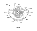
- FIG. 9 is a top elevational view of the refill of FIG. 7 ;
- FIG. 10 is a front elevational view of the volatile material dispenser of FIG. 4 with the refill of FIGS. 7-9 inserted therein in a first orientation;
- FIG. 11 is a front elevational view of the volatile material dispenser of FIG. 4 with the refill of FIGS. 7-9 inserted therein in a second orientation;
- FIG. 12 is a top isometric view of another refill that may be inserted into the volatile material dispensers disclosed herein;
- FIG. 13 is a side elevational view of the refill of FIG. 12 ;
- FIG. 14 is a front elevational view of the volatile material dispenser of FIG. 4 with the refill of FIGS. 12 and 13 inserted therein in a first orientation.
- the present invention is directed to volatile material dispensers for vaporizing and dispensing volatile materials. While the present invention may be embodied in many different forms, several specific embodiments are discussed herein with the understanding that the present invention is to be considered only as an exemplification of the principles of the invention, and it is not intended to limit the invention to the embodiments illustrated.
- volatile material refers to any volatile material that a consumer may desire to emit into an area surrounding one or more refills holding the volatile material(s) and/or a dispenser holding one or more refills.
- the types of volatile materials may be, for example, a cleaner, an insecticide, an insect repellant, an insect attractant, a mold or mildew inhibitor, a fragrance, a disinfectant, an air purifier, an aromatherapy scent, an antiseptic, a positive fragrancing volatile material, an air-freshener, a deodorizer, or the like, and combinations thereof.
- Additives may be included in the volatile material, such as, for example, fragrances and/or preservatives.
- a first embodiment of a volatile material dispenser 20 of the present invention includes a housing 22 formed from a front cover 24 and a rear cover 26 .
- a chassis 28 ( FIGS. 3 and 4 ) is disposed within the housing 22 between the front and rear covers 24 , 26 and supports various components, such as, a plug assembly 28 ( FIGS. 2, 5, and 6 ), a printed circuit board (not shown), a fan 30 ( FIGS. 3 and 4 ), first and second ceramic heating bodies 32 a , 32 b ( FIGS. 3 and 4 ), first and second light emitting diodes (LEDs) 34 a , 34 b (only 34 a shown FIGS. 3 and 4 ), and a selector switch 36 ( FIGS. 1 and 2 ).
- a plug assembly 28 FIGS. 2, 5, and 6
- a printed circuit board not shown
- a fan 30 FIGS. 3 and 4
- first and second ceramic heating bodies 32 a , 32 b FIGS. 3 and 4
- the chassis 28 generally includes first and second generally cylindrical structures 40 a , 40 b forming first and second channels 42 a , 42 b , respectively, wherein the first and second ceramic heating bodies 32 a , 32 b are disposed above the first and second generally cylindrical structures 40 a , 40 b , respectively.
- the heating bodies 32 a , 32 b further include channels 44 a , 44 b formed therethrough to accommodate wicks, wherein the channels 44 a , 44 b are aligned with the channels 42 a , 42 b through the cylindrical structures 40 a , 40 b to accommodate wicks.
- the chassis 28 further includes first and second chimneys 46 a , 46 b that are disposed above and aligned with the first and second heating bodies 32 a , 32 b , respectively.
- the PCB is disposed within the chassis 28 behind the heating bodies 32 a , 32 b , cylindrical structures 40 a , 40 b , and the chimneys 46 a , 46 b , wherein the first and second LEDs 34 a , 34 b extend from the PCB to points adjacent rear surfaces of the first and second chimneys 46 a , 46 b , respectively, to illuminate same.
- the chassis 28 further includes a generally horizontal member 60 disposed at lower ends of the cylindrical structures 40 a , 40 b and a generally vertical member 62 that is perpendicular to and extends downwardly from a central portion 64 of the horizontal member 60 .
- a lower end 66 of the vertical member 62 is curved and includes curved ledges 68 a , 68 b extending from opposing sides 70 a , 70 b thereof and being generally perpendicular to the vertical member 62 .
- the volatile material dispenser 20 includes a number of retention features or implements that aid in retaining a refill therein in more than one orientation, wherein such retention features will be discussed in greater detail hereinafter.
- the dispenser 20 includes a first retention feature including a plurality of stationary ribs 80 a , 80 b disposed on inner surfaces along a height (parallel to a vertical axis of the dispenser) of each of the cylindrical structures 40 a , 40 b and extending into the channels 42 a , 42 b formed by the cylindrical structures 40 a , 40 b .
- a first retention feature including a plurality of stationary ribs 80 a , 80 b disposed on inner surfaces along a height (parallel to a vertical axis of the dispenser) of each of the cylindrical structures 40 a , 40 b and extending into the channels 42 a , 42 b formed by the cylindrical structures 40 a , 40 b .
- seven ribs are depicted on each cylindrical structure 40 a , 40
- a second retention features includes flexible, movable ribs 82 a , 82 b forming a part of the cylindrical structures 40 a , 40 b and extending into the channels 42 a , 42 b formed by the cylindrical structures 40 a , 40 b .
- the movable ribs 82 a , 82 b are connected to the cylindrical structures 40 a , 40 b by a hinge or other flexible structure that allows lower ends 84 a , 84 b of the ribs 82 a , 82 b to move in and out of the respective channels 42 a , 42 b .
- movable rib 82 a , 82 b is depicted in each cylindrical structure 40 a , 40 b , any number of movable ribs 82 a , 82 b may be utilized.
- the function of the ribs 80 a , 80 b , 82 b , 82 b will be discussed in greater detail hereinafter.
- a third retention feature includes first and second latches 100 a , 100 b extending downwardly from the horizontal member 60 and spaced from the respective cylindrical structures 40 a , 40 b .
- Each of the latches 100 a , 100 b includes a downwardly extending member 102 a , 102 b and an inwardly extending projection 104 a , 104 b .
- the curved ledges 68 a , 68 b described above provide a fourth retention feature. The function of the ledges 68 a , 68 b and the latches 100 a , 100 b will be discussed in greater detail hereinafter.
- the first channel 42 a , the vertical member 62 , the ledge 68 a , the stationary ribs 80 a , the movable ribs 82 a , and the latch 100 a are formed within a first cavity 110 a of the dispenser 20 and provide a first retention housing 112 a for the retention of a first refill.
- the second channel 42 b , the vertical member 62 , the ledge 68 b , the stationary ribs 80 b , the movable ribs 82 b , and the latch 100 b are formed within a second cavity 110 b of the dispenser 20 and provide a second retention housing 112 b for the retention of a second refill.
- a first refill 200 capable of insertion into the volatile material dispenser 20 is depicted in FIGS. 7-9 .
- the refill 200 generally includes a container portion 202 that holds a volatile material, wherein a cylindrical neck portion 204 extends upwardly from the container portion 202 .
- a plug assembly 206 is disposed within and attached to the neck portion 204 of the refill 200 .
- a wick 208 is disposed in contact with the volatile material inside the container portion 202 and extends upwardly through the neck portion 204 , such that a portion of the wick 208 is exposed to a surrounding environment.
- the wick 208 is retained within the neck portion 204 by the plug assembly 206 , wherein a sheath 209 extends upwardly from the plug assembly 206 to surround a portion of the wick 208 .
- a thread 210 is disposed on the neck portion 204 , wherein the thread 210 may retain a cap (not shown) thereon and/or may aid in retaining the refill 200 within the dispenser 200 , as discussed in greater detail hereinafter.
- the container portion 202 of the refill 200 includes front and rear surfaces 212 a , 212 b and first and second side surfaces 212 c , 212 d connecting the front and rear surfaces 212 a , 212 b .
- the front surface 212 a has a generally bulbous central portion and is generally curved inwardly at sides and a bottom thereof and the rear surface 212 b is generally planar.
- the side surfaces 212 c , 212 d begin at the neck portion 204 and curve outwardly at top portions 214 thereof and inwardly at bottom portions 216 thereof to generally form a heart shape that is truncated at a bottom surface 218 thereof.
- a shell-shaped protrusion 220 extends outwardly from the front surface 212 a and a semi-cylindrical projection 222 extends outwardly from the rear surface 212 b along a height of the container portion 202 .
- FIGS. 10 and 11 depict the refill 200 inserted into and retained within the second retention housing 112 b of the dispenser 20 in first and second orientations, respectively.
- the wick 208 and sheath 209 are inserted into the channel 42 a and the refill 200 is pushed upwardly until the latch 100 b meets the thread 210 on the refill 200 .
- an interference between the thread 210 and the projection 104 b on the latch 100 b causes the latch 100 b to flex outwardly until the thread 210 passes the projection 104 b .
- the stationary ribs 80 b create an interference fit between the sheath 209 surrounding the wick 208 of the refill 200 .
- the movable rib 82 b allows for a bit of give or movement of the wick 208 and sheath 209 such that the interference fit is not too tight.
- the stationary ribs 80 b and movable rib 82 b create a horizontal load on the sheath 209 that aids in retaining the wick 208 within the channel 42 a .
- the refill 200 is in a retained position, wherein the stationary and movable ribs 80 b , 82 b partially retain the wick 208 and the sheath 209 in place, the projection 104 b extending from the latch 100 b interferes with the thread 210 to prevent downward movement of the refill 200 , and the protrusion 220 extending from the refill 200 sits on the ledge 68 b to also prevent downwardly movement of the refill 200 .
- the refill 200 has been rotated 180 degrees about a vertical axis 230 ( FIGS. 8 and 9 ) of the refill 200 .
- the wick 208 and sheath 209 are inserted and retained in the same manner as with the first orientation (by the stationary and movable ribs 80 b , 82 b ).
- the projection 104 b extending from the latch 100 b provides an interference with the thread 210 to prevent downward movement of the refill 200 .
- the refill 200 is not retained in any way by the protrusion 220 extending therefrom.
- any annular member, projection, or other structure that interacts with the latch 100 b to prevent downward movement may alternatively be utilized. Still alternatively, the thread 210 may be discontinuous.
- the refill 200 can be retained in first and second orientations within the first retention housing 112 a .
- the protrusion 220 extending from the refill 200 is captured by the ledge 68 a and in the second orientation, the protrusion 220 extends outwardly away from the ledge 68 a and is not utilized to retain the refill 200 within the dispenser 20 .
- FIGS. 12 and 13 A further refill 300 capable of insertion into the volatile material dispenser 20 is depicted in FIGS. 12 and 13 .
- the refill 300 includes a container 302 , a neck portion 304 extending upwardly from the container 302 , a wick 306 in contact with a volatile material in the container 302 and extending out the neck portion 304 , and a plug assembly 308 for holding the wick 306 within the neck portion 304 .
- the container 302 includes a body 310 that is generally symmetrical about the neck portion 304 and includes opposing front and rear walls 312 a , 312 b and opposing side walls 314 a , 314 b .
- Shell-shaped protrusions 316 a , 316 b extend outwardly from the front and rear walls 312 a , 312 b , respectively.
- the protrusions 316 a , 316 b may alternatively have any other suitable shape.
- the neck portion 304 includes a thread 320 disposed on an outer surface thereof for attachment of a cap (not shown) thereto and the plug assembly 308 includes a sheath 322 extending upwardly therefrom, wherein the sheath 322 surrounds at least a portion of the wick 306 .
- FIG. 14 depicts the refill 300 inserted into and retained within the second retention housing 112 b of the dispenser 20 in a first orientation. Because the refill 300 is symmetrical about the neck portion 304 thereof, the refill 300 fits within the dispenser 20 in the same exact manner for the second orientation, so only the first orientation will be discussed herein.
- the wick 306 and sheath 322 are inserted into the channel 42 a and the refill 300 is pushed upwardly.
- the stationary ribs 80 b create an interference fit with the sheath 322 surrounding the wick 306 of the refill 300 (by way of a horizontal load being applied to the sheath 322 ), as discussed in detail above.
- the movable rib 82 b allows for a bit of give or movement of the wick 306 and sheath 322 such that the interference fit is not too tight.
- the protrusion 316 a extending from the refill 300 sits on the ledge 68 b to prevent downward movement of the refill 300 .
- the protrusion 316 b would prevent downward movement of the refill 300 in the same manner.
- dispensers 30 are described as having certain electrical features (LEDs, fan, heaters, etc.), the principles of the present invention may be utilized in dispensers having different electrical features.
- the present invention provides volatile material dispensers that include multiple retention features to hold and retain one or more refills in different orientations. Specifically, the different retention features allow the refills to be inserted into and retained by the volatile material dispenser in one of two orientations.
Abstract
A method of attaching a refill to a volatile material dispenser includes the step of providing a volatile material dispenser that includes a housing, a first implement that attaches a refill containing a volatile material to the housing, and a second implement that attaches the refill to the housing, wherein the first and second implements include different features. The method further includes the step of attaching the refill in a first orientation to the volatile material dispenser, wherein in the first orientation, the first implement retains the refill. Still further, the method includes the step of attaching the refill in a second orientation different than the first orientation to the volatile material dispenser, wherein in the second orientation, the second implement retains the refill.
Description
Not applicable.
Not applicable
Not applicable
1. Field of the Invention
The present invention relates generally to volatile material dispensers and, more particularly, to volatile material dispensers having one or more retention features for coupling a refill thereto.
2. Description of the Background of the Invention
Multiple different volatile material dispensers are commercially sold and generally include a housing and a volatile material refill that is inserted into the housing. The refill generally includes a container or bottle for holding a volatile material therein. In some dispensers, the volatile material is passively emitted therefrom. In other dispensers, a diffusion element is utilized to facilitate the dispensing of the volatile material. Examples of diffusion elements include heaters, piezoelectric elements, fans, aerosol actuators, and the like. Regardless of the manner in which the volatile material is emitted, once the volatile material has been expended from the refill, the refill can typically be removed by a user and replaced with a new refill.
One type of commercial volatile material dispenser, referred to herein as a plug-in scented oil dispenser, includes a housing and a heater disposed within the housing. A refill for use with a plug-in scented oil dispenser generally includes a container portion having a bottom end and a top end, wherein the container portion terminates in a neck portion at the top end. A volatile material is disposed within the container portion and a wick is in contact with the volatile material and extends out of the refill through the neck portion. A plug or other connector generally positions and retains the wick within the neck portion. Upon insertion of the refill into the dispenser, at least a portion of the wick is disposed adjacent the heater such that volatile material that moves through the wick is volatilized by the heater.
Another feature of various volatile material dispensers and refills is that each refill has features that are unique or complementary to the particular dimensions of the housing of the dispenser for which it is sold. Still further, each refill has a feature that interacts with a further feature in the dispenser for which it is manufactured to retain the refill within the dispenser.
According to one embodiment, a method of attaching a refill to a volatile material dispenser includes the step of providing a volatile material dispenser that includes a housing, a first implement that attaches a refill containing a volatile material to the housing, and a second implement that attaches the refill to the housing, wherein the first and second implements include different features. The method further includes the step of attaching the refill in a first orientation to the volatile material dispenser, wherein in the first orientation, the first implement retains the refill. Still further, the method includes the step of attaching the refill in a second orientation different than the first orientation to the volatile material dispenser, wherein in the second orientation, the second implement retains the refill.
According to another embodiment, a volatile material dispenser includes a housing, a first implement that secures a refill having a volatile material therein to the housing, and a second implement that secures the refill to the housing, wherein the second implement is different than the first implement. The first implement is capable of retaining the refill when the refill is disposed in a first orientation and the second implement is capable of retaining the refill when the refill is disposed in a second, different orientation.
According to yet another embodiment, a method of attaching two or more refills to a volatile material dispenser includes the step of providing a volatile material dispenser that includes a housing and at least one implement that attaches a refill containing a volatile material to the housing. The method further includes the steps of attaching a first refill to the volatile material dispenser in a first orientation, wherein in the first orientation, at least the implement retains the refill and attaching the first refill to the volatile material dispenser in a second orientation, wherein in the second orientation, at least the implement retains the refill and wherein the first and second orientations are different. The method still further includes the step of attaching a second refill having features different than the first refill to the volatile material dispenser in a third orientation, wherein in the third orientation, at least the implement retains the refill. Additionally, the method includes the step of attaching a second refill to the volatile material dispenser in a fourth orientation, wherein in the fourth orientation, at least the implement retains the refill and wherein the third and fourth orientations are different.
Other aspects and advantages of the present invention will become apparent upon consideration of the following detailed description, wherein similar structures have like or similar reference numerals.
The present invention is directed to volatile material dispensers for vaporizing and dispensing volatile materials. While the present invention may be embodied in many different forms, several specific embodiments are discussed herein with the understanding that the present invention is to be considered only as an exemplification of the principles of the invention, and it is not intended to limit the invention to the embodiments illustrated.
Further, the use of the term volatile material herein refers to any volatile material that a consumer may desire to emit into an area surrounding one or more refills holding the volatile material(s) and/or a dispenser holding one or more refills. Illustratively, the types of volatile materials may be, for example, a cleaner, an insecticide, an insect repellant, an insect attractant, a mold or mildew inhibitor, a fragrance, a disinfectant, an air purifier, an aromatherapy scent, an antiseptic, a positive fragrancing volatile material, an air-freshener, a deodorizer, or the like, and combinations thereof. Additives may be included in the volatile material, such as, for example, fragrances and/or preservatives.
Referring now to FIGS. 1-7 , a first embodiment of a volatile material dispenser 20 of the present invention includes a housing 22 formed from a front cover 24 and a rear cover 26. A chassis 28 (FIGS. 3 and 4 ) is disposed within the housing 22 between the front and rear covers 24, 26 and supports various components, such as, a plug assembly 28 (FIGS. 2, 5, and 6 ), a printed circuit board (not shown), a fan 30 (FIGS. 3 and 4 ), first and second ceramic heating bodies 32 a, 32 b (FIGS. 3 and 4 ), first and second light emitting diodes (LEDs) 34 a, 34 b (only 34 a shown FIGS. 3 and 4 ), and a selector switch 36 (FIGS. 1 and 2 ).
Referring to FIGS. 3 and 4 , the chassis 28 generally includes first and second generally cylindrical structures 40 a, 40 b forming first and second channels 42 a, 42 b, respectively, wherein the first and second ceramic heating bodies 32 a, 32 b are disposed above the first and second generally cylindrical structures 40 a, 40 b, respectively. The heating bodies 32 a, 32 b further include channels 44 a, 44 b formed therethrough to accommodate wicks, wherein the channels 44 a, 44 b are aligned with the channels 42 a, 42 b through the cylindrical structures 40 a, 40 b to accommodate wicks. The chassis 28 further includes first and second chimneys 46 a, 46 b that are disposed above and aligned with the first and second heating bodies 32 a, 32 b, respectively. The PCB is disposed within the chassis 28 behind the heating bodies 32 a, 32 b, cylindrical structures 40 a, 40 b, and the chimneys 46 a, 46 b, wherein the first and second LEDs 34 a, 34 b extend from the PCB to points adjacent rear surfaces of the first and second chimneys 46 a, 46 b, respectively, to illuminate same.
As seen in FIGS. 2-7 , the chassis 28 further includes a generally horizontal member 60 disposed at lower ends of the cylindrical structures 40 a, 40 b and a generally vertical member 62 that is perpendicular to and extends downwardly from a central portion 64 of the horizontal member 60. A lower end 66 of the vertical member 62 is curved and includes curved ledges 68 a, 68 b extending from opposing sides 70 a, 70 b thereof and being generally perpendicular to the vertical member 62.
The volatile material dispenser 20 includes a number of retention features or implements that aid in retaining a refill therein in more than one orientation, wherein such retention features will be discussed in greater detail hereinafter. Specifically, as seen in FIGS. 5 and 6 , the dispenser 20 includes a first retention feature including a plurality of stationary ribs 80 a, 80 b disposed on inner surfaces along a height (parallel to a vertical axis of the dispenser) of each of the cylindrical structures 40 a, 40 b and extending into the channels 42 a, 42 b formed by the cylindrical structures 40 a, 40 b. Although seven ribs are depicted on each cylindrical structure 40 a, 40 b, any number of ribs may be utilized. A second retention features includes flexible, movable ribs 82 a, 82 b forming a part of the cylindrical structures 40 a, 40 b and extending into the channels 42 a, 42 b formed by the cylindrical structures 40 a, 40 b. The movable ribs 82 a, 82 b are connected to the cylindrical structures 40 a, 40 b by a hinge or other flexible structure that allows lower ends 84 a, 84 b of the ribs 82 a, 82 b to move in and out of the respective channels 42 a, 42 b. Although only a single movable rib 82 a, 82 b is depicted in each cylindrical structure 40 a, 40 b, any number of movable ribs 82 a, 82 b may be utilized. The function of the ribs 80 a, 80 b, 82 b, 82 b will be discussed in greater detail hereinafter.
Still referring to FIGS. 5 and 6 , a third retention feature includes first and second latches 100 a, 100 b extending downwardly from the horizontal member 60 and spaced from the respective cylindrical structures 40 a, 40 b. Each of the latches 100 a, 100 b includes a downwardly extending member 102 a, 102 b and an inwardly extending projection 104 a, 104 b. The curved ledges 68 a, 68 b described above provide a fourth retention feature. The function of the ledges 68 a, 68 b and the latches 100 a, 100 b will be discussed in greater detail hereinafter.
The first channel 42 a, the vertical member 62, the ledge 68 a, the stationary ribs 80 a, the movable ribs 82 a, and the latch 100 a are formed within a first cavity 110 a of the dispenser 20 and provide a first retention housing 112 a for the retention of a first refill. Likewise, the second channel 42 b, the vertical member 62, the ledge 68 b, the stationary ribs 80 b, the movable ribs 82 b, and the latch 100 b are formed within a second cavity 110 b of the dispenser 20 and provide a second retention housing 112 b for the retention of a second refill.
A first refill 200 capable of insertion into the volatile material dispenser 20 is depicted in FIGS. 7-9 . The refill 200 generally includes a container portion 202 that holds a volatile material, wherein a cylindrical neck portion 204 extends upwardly from the container portion 202. A plug assembly 206 is disposed within and attached to the neck portion 204 of the refill 200. A wick 208 is disposed in contact with the volatile material inside the container portion 202 and extends upwardly through the neck portion 204, such that a portion of the wick 208 is exposed to a surrounding environment. The wick 208 is retained within the neck portion 204 by the plug assembly 206, wherein a sheath 209 extends upwardly from the plug assembly 206 to surround a portion of the wick 208. A thread 210 is disposed on the neck portion 204, wherein the thread 210 may retain a cap (not shown) thereon and/or may aid in retaining the refill 200 within the dispenser 200, as discussed in greater detail hereinafter.
The container portion 202 of the refill 200 includes front and rear surfaces 212 a, 212 b and first and second side surfaces 212 c, 212 d connecting the front and rear surfaces 212 a, 212 b. The front surface 212 a has a generally bulbous central portion and is generally curved inwardly at sides and a bottom thereof and the rear surface 212 b is generally planar. Further, and referring to FIG. 7 , the side surfaces 212 c, 212 d begin at the neck portion 204 and curve outwardly at top portions 214 thereof and inwardly at bottom portions 216 thereof to generally form a heart shape that is truncated at a bottom surface 218 thereof. A shell-shaped protrusion 220 extends outwardly from the front surface 212 a and a semi-cylindrical projection 222 extends outwardly from the rear surface 212 b along a height of the container portion 202.
In the second orientation of FIG. 11 , the refill 200 has been rotated 180 degrees about a vertical axis 230 (FIGS. 8 and 9 ) of the refill 200. In such orientation, the wick 208 and sheath 209 are inserted and retained in the same manner as with the first orientation (by the stationary and movable ribs 80 b, 82 b). Additionally, the projection 104 b extending from the latch 100 b provides an interference with the thread 210 to prevent downward movement of the refill 200. In this orientation, the refill 200 is not retained in any way by the protrusion 220 extending therefrom.
Although a thread 210 is utilized to interact with the latch 100 b, any annular member, projection, or other structure that interacts with the latch 100 b to prevent downward movement may alternatively be utilized. Still alternatively, the thread 210 may be discontinuous.
Although the refill 200 is shown inserted into and retained within the second retention housing 112 b, the refill 200 can be retained in first and second orientations within the first retention housing 112 a. In particular, in the first orientation, the protrusion 220 extending from the refill 200 is captured by the ledge 68 a and in the second orientation, the protrusion 220 extends outwardly away from the ledge 68 a and is not utilized to retain the refill 200 within the dispenser 20.
A further refill 300 capable of insertion into the volatile material dispenser 20 is depicted in FIGS. 12 and 13 . The refill 300 includes a container 302, a neck portion 304 extending upwardly from the container 302, a wick 306 in contact with a volatile material in the container 302 and extending out the neck portion 304, and a plug assembly 308 for holding the wick 306 within the neck portion 304. The container 302 includes a body 310 that is generally symmetrical about the neck portion 304 and includes opposing front and rear walls 312 a, 312 b and opposing side walls 314 a, 314 b. Shell-shaped protrusions 316 a, 316 b extend outwardly from the front and rear walls 312 a, 312 b, respectively. The protrusions 316 a, 316 b may alternatively have any other suitable shape. The neck portion 304 includes a thread 320 disposed on an outer surface thereof for attachment of a cap (not shown) thereto and the plug assembly 308 includes a sheath 322 extending upwardly therefrom, wherein the sheath 322 surrounds at least a portion of the wick 306.
Although terms such as vertical, horizontal, downward, inward, etc. are utilized throughout the present application, such terms are not meant to limit the present invention, but instead, give relative direction when the dispenser 20 and/or refills 200, 300 are placed in a use position. Still further, although the dispensers 30 herein are described as having certain electrical features (LEDs, fan, heaters, etc.), the principles of the present invention may be utilized in dispensers having different electrical features.
Although multiple retention features are described herein, not all of such retention features are necessary for the present invention. Further, other refills having different shapes, sizes, and/or configurations may be utilized with the dispensers herein, so long as the appropriate retention features are present and capable of attachment with the dispensers.
Any of the embodiments described herein may be modified to include any of the structures or methodologies disclosed in connection with other embodiments.
The present invention provides volatile material dispensers that include multiple retention features to hold and retain one or more refills in different orientations. Specifically, the different retention features allow the refills to be inserted into and retained by the volatile material dispenser in one of two orientations.
Numerous modifications to the present disclosure will be apparent to those skilled in the art in view of the foregoing description. Accordingly, this description is to be construed as illustrative only and is presented to enable those skilled in the art to make and use the disclosure and to teach the best mode of carrying out same. The exclusive rights to all modifications that come within the scope of the appended claims are reserved.
Claims (5)
1. A method of attaching a refill to a volatile material dispenser, the method comprising the steps of:
providing a volatile material dispenser that includes a housing having first and second cavities disposed within the housing and each cavity adapted to accommodate a refill, each cavity includes a first implement formed within the cavity and which attaches a refill containing a volatile material to the housing by interacting with a neck portion of the refill, and a second implement formed within the cavity and which attaches the refill to the housing by interacting with a container portion of the refill;
inserting the refill into one of the first cavity or the second cavity and attaching the refill in a first orientation to the volatile material dispenser, wherein in the first orientation, the first implement and the second implement retain the refill; and
inserting the refill into one of the first cavity or the second cavity and attaching the refill in a second orientation to the volatile material dispenser, wherein in the second orientation, the first implement retains the refill.
2. The method of claim 1 , wherein in the second orientation, the refill is oriented 180 degrees from an orientation of the refill in the first orientation.
3. The method of claim 2 , wherein the first orientation of the refill inserted into the second cavity is oriented 180 degrees from the first orientation of the refill inserted into the first cavity.
4. The method of claim 3 , wherein the first implement includes at least one of a plurality of stationary ribs, a movable rib, and a latch, wherein the plurality of stationary ribs and the movable rib create an interference with a sheath covering at least a portion of a wick that extends from the refill, and the latch that interacts with the neck portion of the refill, wherein the first implement attaches the refill to the housing by preventing downward movement of the refill.
5. The method of claim 4 , wherein the second implement includes a ledge that interacts with a protrusion extending from the container portion of the refill to prevent downward movement of the refill.
Priority Applications (7)
| Application Number | Priority Date | Filing Date | Title |
|---|---|---|---|
| US12/837,948 US9770524B2 (en) | 2010-07-16 | 2010-07-16 | Volatile material dispenser and method of attaching a refill or refills to same |
| CN201180042696.9A CN103096939B (en) | 2010-07-16 | 2011-07-15 | Volatile material dispenser and method of attaching a refill or refills to same |
| PCT/US2011/001252 WO2012009016A1 (en) | 2010-07-16 | 2011-07-15 | Volatile material dispenser and method of attaching a refill or refills to same |
| MX2013000641A MX2013000641A (en) | 2010-07-16 | 2011-07-15 | Volatile material dispenser and method of attaching a refill or refills to same. |
| EP11740998.7A EP2593146B1 (en) | 2010-07-16 | 2011-07-15 | Volatile material dispenser and method of attaching a refill or refills to same |
| ES11740998.7T ES2487655T3 (en) | 2010-07-16 | 2011-07-15 | Volatile material dispenser and method of holding a recharge or refills to it |
| US14/608,650 US20150135503A1 (en) | 2010-07-16 | 2015-01-29 | Method of attaching two or more different refills to a volatile material dispenser |
Applications Claiming Priority (1)
| Application Number | Priority Date | Filing Date | Title |
|---|---|---|---|
| US12/837,948 US9770524B2 (en) | 2010-07-16 | 2010-07-16 | Volatile material dispenser and method of attaching a refill or refills to same |
Related Child Applications (1)
| Application Number | Title | Priority Date | Filing Date |
|---|---|---|---|
| US14/608,650 Continuation US20150135503A1 (en) | 2010-07-16 | 2015-01-29 | Method of attaching two or more different refills to a volatile material dispenser |
Publications (2)
| Publication Number | Publication Date |
|---|---|
| US20120012668A1 US20120012668A1 (en) | 2012-01-19 |
| US9770524B2 true US9770524B2 (en) | 2017-09-26 |
Family
ID=44629722
Family Applications (2)
| Application Number | Title | Priority Date | Filing Date |
|---|---|---|---|
| US12/837,948 Active 2034-10-21 US9770524B2 (en) | 2010-07-16 | 2010-07-16 | Volatile material dispenser and method of attaching a refill or refills to same |
| US14/608,650 Abandoned US20150135503A1 (en) | 2010-07-16 | 2015-01-29 | Method of attaching two or more different refills to a volatile material dispenser |
Family Applications After (1)
| Application Number | Title | Priority Date | Filing Date |
|---|---|---|---|
| US14/608,650 Abandoned US20150135503A1 (en) | 2010-07-16 | 2015-01-29 | Method of attaching two or more different refills to a volatile material dispenser |
Country Status (6)
| Country | Link |
|---|---|
| US (2) | US9770524B2 (en) |
| EP (1) | EP2593146B1 (en) |
| CN (1) | CN103096939B (en) |
| ES (1) | ES2487655T3 (en) |
| MX (1) | MX2013000641A (en) |
| WO (1) | WO2012009016A1 (en) |
Cited By (3)
| Publication number | Priority date | Publication date | Assignee | Title |
|---|---|---|---|---|
| US20180103507A1 (en) * | 2016-10-07 | 2018-04-12 | S. C. Johnson & Son, Inc. | Volatile material dispenser |
| DE202018001920U1 (en) | 2018-04-14 | 2018-05-24 | Adam Esmurziev | Fragrance emitting device with combinable fragrance notes |
| USD880023S1 (en) | 2018-12-27 | 2020-03-31 | Steven Goldmeier | Scented night light |
Families Citing this family (5)
| Publication number | Priority date | Publication date | Assignee | Title |
|---|---|---|---|---|
| US10155059B2 (en) | 2015-03-06 | 2018-12-18 | Personal Care Products, LLC | Volatile material dispenser |
| USD871226S1 (en) | 2017-10-23 | 2019-12-31 | S. C. Johnson & Son, Inc. | Container |
| USD846725S1 (en) | 2017-10-23 | 2019-04-23 | S. C. Johnson & Son, Inc. | Dispenser |
| USD859163S1 (en) | 2017-10-23 | 2019-09-10 | S. C. Johnson & Son, Inc. | Container with cover |
| USD846724S1 (en) | 2017-10-23 | 2019-04-23 | S. C. Johnson & Son, Inc. | Dispenser |
Citations (41)
| Publication number | Priority date | Publication date | Assignee | Title |
|---|---|---|---|---|
| GB1513953A (en) | 1974-05-15 | 1978-06-14 | Ciba Geigy Ag | Evaporator-block container |
| ES278519U (en) | 1984-03-30 | 1985-02-16 | Reckitt & Colman S.A. | An air freshener device (Machine-translation by Google Translate, not legally binding) |
| US5038394A (en) | 1988-02-10 | 1991-08-06 | Earth Chemical Co., Ltd. | Thermal vaporizer |
| EP0451331A1 (en) | 1990-04-11 | 1991-10-16 | Globol GmbH | Electrical device for evaporating substances of efficacy |
| US5222186A (en) | 1991-12-06 | 1993-06-22 | Globol Gmbh | Electrical apparatus for vaporizing of active substances |
| DE4433954A1 (en) | 1994-09-23 | 1996-03-28 | Bayer Ag | Evaporation container |
| US5779101A (en) | 1996-11-12 | 1998-07-14 | Illinois Tool Works Inc. | Portable carrier for aerosol containers and method therefor |
| WO2000076292A2 (en) | 1999-06-16 | 2000-12-21 | The Dial Corporation | Liquid vaporization with housing stabilization system |
| US6236807B1 (en) | 2000-01-07 | 2001-05-22 | Bath & Body Works, Inc. | Wick-based liquid emanation system with child-resistant and miniaturization features |
| US6278840B1 (en) | 1997-06-24 | 2001-08-21 | Dbk Espana, S.A. | Evaporator device of volatile products with variable evaporation intensity |
| US6466739B2 (en) | 2000-07-28 | 2002-10-15 | Zobele Holding S.P.A. | Electric evaporator for insecticides or perfumes in liquid formulation, with adjustable evaporation intensity |
| US6569387B1 (en) | 1999-08-10 | 2003-05-27 | S.C. Johnson & Son, Inc. | Dual function dispenser |
| US6603924B2 (en) | 2001-04-09 | 2003-08-05 | Zelnova, S.A. | Thermal vaporizer, container for the thermal vaporizer and a thermal vaporizer assembly |
| US20030189022A1 (en) | 2002-04-08 | 2003-10-09 | Fellows Robert Terrence | Liquid vaporization device and bottle |
| US6697571B2 (en) | 2002-03-11 | 2004-02-24 | The Dial Corporation | Method and apparatus for selective positioning a wick material in a vapor-dispensing device |
| US6722532B2 (en) | 2000-10-20 | 2004-04-20 | L'oreal | Dispenser unit for simultaneously dispensing the contents of two containers |
| US6783117B2 (en) | 2000-07-10 | 2004-08-31 | Gregory D. Wohrle | Scent delivery system |
| US20040182949A1 (en) | 2003-03-21 | 2004-09-23 | Duston Tyler D. | Container for a device for dispensing a volatile liquid |
| US20040247301A1 (en) | 2003-05-01 | 2004-12-09 | Yip Po Chun | Multi-fragrance scent dispenser |
| US6862403B2 (en) | 2001-08-07 | 2005-03-01 | S.C. Johnson & Son, Inc. | Rotatable plug assembly including an extra outlet |
| US6917754B2 (en) | 2001-08-07 | 2005-07-12 | S.C. Johnson & Son, Inc. | Multi-functional electrical vaporizer for a liquid substance and method of manufacturing such a vaporizer |
| US6931202B2 (en) | 2000-07-28 | 2005-08-16 | S.C. Johnson & Son, Inc. | Electrical evaporator with adjustable evaporation intensity |
| US20060043619A1 (en) | 2002-11-12 | 2006-03-02 | Givaudan Sa | Powered dispensing devices for the delivery of evaporable materials |
| US20060110144A1 (en) | 2004-11-09 | 2006-05-25 | Fellows Robert T | Bottle for liquid vaporization device |
| US20060249593A1 (en) | 2003-04-30 | 2006-11-09 | Givaudan Sa | Dispensing device and method |
| US20070048173A1 (en) * | 2004-08-31 | 2007-03-01 | Keller Leonard J Jr | Device and containers for emitting volatile compositions |
| US20080011874A1 (en) | 2006-07-14 | 2008-01-17 | Munagavalasa Murthy S | Diffusion device |
| US7324744B2 (en) | 2005-09-08 | 2008-01-29 | The Dial Corporation | Multi-orientation low profile dual outlet volatile dispenser |
| US7341698B2 (en) * | 2002-04-10 | 2008-03-11 | S.C. Johnson & Son, Inc. | Electrical evaporator including fan and louver structure |
| US7344123B2 (en) | 2001-10-04 | 2008-03-18 | Carbonate Limited | Dispersing fragrances |
| US7389943B2 (en) | 2004-06-30 | 2008-06-24 | S.C. Johnson & Son, Inc. | Electromechanical apparatus for dispensing volatile substances with single dispensing mechanism and cartridge for holding multiple receptacles |
| US7400822B2 (en) | 2002-04-12 | 2008-07-15 | Zobele Espana, S.A. | Active substance evaporator |
| US20080279731A1 (en) | 2005-10-16 | 2008-11-13 | Reckitt Benckiser (Uk) Limited | Device |
| GB2449703A (en) | 2007-06-01 | 2008-12-03 | Jeyes Group Ltd | Plug-in fragrancer |
| USD584809S1 (en) | 2008-02-04 | 2009-01-13 | S. C. Johnson & Son, Inc. | Dispensing device |
| US7497354B2 (en) | 2002-10-09 | 2009-03-03 | Airlessystems | Fluid dispenser |
| US7544332B2 (en) | 2007-03-12 | 2009-06-09 | S.C. Johnson & Son, Inc. | Air treatment dispensers delivering multiple chemicals |
| US20090212124A1 (en) | 2007-09-12 | 2009-08-27 | Kevin Brian Kenny | Apparatus and method for dispensing a volatile composition |
| US20090218413A1 (en) | 2005-10-24 | 2009-09-03 | Intellectual Property Development Corporation Pty | Dispensing Devices |
| US20100061896A1 (en) | 2008-09-05 | 2010-03-11 | Hyso Technology Llc | Multi cartridge air freshener |
| US20100102088A1 (en) | 2007-03-19 | 2010-04-29 | Sulzer Mixpac Ag | Dispensing Assembly Having Removably Attachable Accessories |
Family Cites Families (2)
| Publication number | Priority date | Publication date | Assignee | Title |
|---|---|---|---|---|
| FR2880279A1 (en) * | 2005-01-05 | 2006-07-07 | Cvb Sarl Sarl | MULTI-ODOR DIFFUSION DEVICE |
| WO2011081657A2 (en) * | 2009-12-15 | 2011-07-07 | S. C. Johnson & Son, Inc. | Refill, attachment for a refill, and method of retaining a refill |
-
2010
- 2010-07-16 US US12/837,948 patent/US9770524B2/en active Active
-
2011
- 2011-07-15 MX MX2013000641A patent/MX2013000641A/en not_active Application Discontinuation
- 2011-07-15 ES ES11740998.7T patent/ES2487655T3/en active Active
- 2011-07-15 CN CN201180042696.9A patent/CN103096939B/en not_active Expired - Fee Related
- 2011-07-15 WO PCT/US2011/001252 patent/WO2012009016A1/en active Application Filing
- 2011-07-15 EP EP11740998.7A patent/EP2593146B1/en active Active
-
2015
- 2015-01-29 US US14/608,650 patent/US20150135503A1/en not_active Abandoned
Patent Citations (45)
| Publication number | Priority date | Publication date | Assignee | Title |
|---|---|---|---|---|
| GB1513953A (en) | 1974-05-15 | 1978-06-14 | Ciba Geigy Ag | Evaporator-block container |
| ES278519U (en) | 1984-03-30 | 1985-02-16 | Reckitt & Colman S.A. | An air freshener device (Machine-translation by Google Translate, not legally binding) |
| US5038394A (en) | 1988-02-10 | 1991-08-06 | Earth Chemical Co., Ltd. | Thermal vaporizer |
| EP0451331A1 (en) | 1990-04-11 | 1991-10-16 | Globol GmbH | Electrical device for evaporating substances of efficacy |
| US5222186A (en) | 1991-12-06 | 1993-06-22 | Globol Gmbh | Electrical apparatus for vaporizing of active substances |
| DE4433954A1 (en) | 1994-09-23 | 1996-03-28 | Bayer Ag | Evaporation container |
| US5779101A (en) | 1996-11-12 | 1998-07-14 | Illinois Tool Works Inc. | Portable carrier for aerosol containers and method therefor |
| US6278840B1 (en) | 1997-06-24 | 2001-08-21 | Dbk Espana, S.A. | Evaporator device of volatile products with variable evaporation intensity |
| WO2000076292A2 (en) | 1999-06-16 | 2000-12-21 | The Dial Corporation | Liquid vaporization with housing stabilization system |
| US20020172512A1 (en) | 1999-06-16 | 2002-11-21 | Stathakis Kristopher J | Liquid vaporization with housing stabilization system |
| US6569387B1 (en) | 1999-08-10 | 2003-05-27 | S.C. Johnson & Son, Inc. | Dual function dispenser |
| US6236807B1 (en) | 2000-01-07 | 2001-05-22 | Bath & Body Works, Inc. | Wick-based liquid emanation system with child-resistant and miniaturization features |
| US6783117B2 (en) | 2000-07-10 | 2004-08-31 | Gregory D. Wohrle | Scent delivery system |
| US6466739B2 (en) | 2000-07-28 | 2002-10-15 | Zobele Holding S.P.A. | Electric evaporator for insecticides or perfumes in liquid formulation, with adjustable evaporation intensity |
| US6931202B2 (en) | 2000-07-28 | 2005-08-16 | S.C. Johnson & Son, Inc. | Electrical evaporator with adjustable evaporation intensity |
| US6722532B2 (en) | 2000-10-20 | 2004-04-20 | L'oreal | Dispenser unit for simultaneously dispensing the contents of two containers |
| US6603924B2 (en) | 2001-04-09 | 2003-08-05 | Zelnova, S.A. | Thermal vaporizer, container for the thermal vaporizer and a thermal vaporizer assembly |
| US6917754B2 (en) | 2001-08-07 | 2005-07-12 | S.C. Johnson & Son, Inc. | Multi-functional electrical vaporizer for a liquid substance and method of manufacturing such a vaporizer |
| US6862403B2 (en) | 2001-08-07 | 2005-03-01 | S.C. Johnson & Son, Inc. | Rotatable plug assembly including an extra outlet |
| US7344123B2 (en) | 2001-10-04 | 2008-03-18 | Carbonate Limited | Dispersing fragrances |
| US6889003B2 (en) | 2002-03-11 | 2005-05-03 | The Dial Corporation | Method and apparatus for positioning a wick material in a vapor-dispensing device |
| US6697571B2 (en) | 2002-03-11 | 2004-02-24 | The Dial Corporation | Method and apparatus for selective positioning a wick material in a vapor-dispensing device |
| US20030189022A1 (en) | 2002-04-08 | 2003-10-09 | Fellows Robert Terrence | Liquid vaporization device and bottle |
| US7341698B2 (en) * | 2002-04-10 | 2008-03-11 | S.C. Johnson & Son, Inc. | Electrical evaporator including fan and louver structure |
| US7400822B2 (en) | 2002-04-12 | 2008-07-15 | Zobele Espana, S.A. | Active substance evaporator |
| US7497354B2 (en) | 2002-10-09 | 2009-03-03 | Airlessystems | Fluid dispenser |
| US20060043619A1 (en) | 2002-11-12 | 2006-03-02 | Givaudan Sa | Powered dispensing devices for the delivery of evaporable materials |
| US20040182949A1 (en) | 2003-03-21 | 2004-09-23 | Duston Tyler D. | Container for a device for dispensing a volatile liquid |
| US20060249593A1 (en) | 2003-04-30 | 2006-11-09 | Givaudan Sa | Dispensing device and method |
| US20040247301A1 (en) | 2003-05-01 | 2004-12-09 | Yip Po Chun | Multi-fragrance scent dispenser |
| US6859615B2 (en) | 2003-05-01 | 2005-02-22 | Hometek International Ltd. | Multi-fragrance scent dispenser |
| US7389943B2 (en) | 2004-06-30 | 2008-06-24 | S.C. Johnson & Son, Inc. | Electromechanical apparatus for dispensing volatile substances with single dispensing mechanism and cartridge for holding multiple receptacles |
| US7722807B2 (en) * | 2004-08-31 | 2010-05-25 | The Procter & Gamble Company | Device and containers for emitting volatile compositions |
| US20070048173A1 (en) * | 2004-08-31 | 2007-03-01 | Keller Leonard J Jr | Device and containers for emitting volatile compositions |
| US20060110144A1 (en) | 2004-11-09 | 2006-05-25 | Fellows Robert T | Bottle for liquid vaporization device |
| US7324744B2 (en) | 2005-09-08 | 2008-01-29 | The Dial Corporation | Multi-orientation low profile dual outlet volatile dispenser |
| US20080279731A1 (en) | 2005-10-16 | 2008-11-13 | Reckitt Benckiser (Uk) Limited | Device |
| US20090218413A1 (en) | 2005-10-24 | 2009-09-03 | Intellectual Property Development Corporation Pty | Dispensing Devices |
| US20080011874A1 (en) | 2006-07-14 | 2008-01-17 | Munagavalasa Murthy S | Diffusion device |
| US7544332B2 (en) | 2007-03-12 | 2009-06-09 | S.C. Johnson & Son, Inc. | Air treatment dispensers delivering multiple chemicals |
| US20100102088A1 (en) | 2007-03-19 | 2010-04-29 | Sulzer Mixpac Ag | Dispensing Assembly Having Removably Attachable Accessories |
| GB2449703A (en) | 2007-06-01 | 2008-12-03 | Jeyes Group Ltd | Plug-in fragrancer |
| US20090212124A1 (en) | 2007-09-12 | 2009-08-27 | Kevin Brian Kenny | Apparatus and method for dispensing a volatile composition |
| USD584809S1 (en) | 2008-02-04 | 2009-01-13 | S. C. Johnson & Son, Inc. | Dispensing device |
| US20100061896A1 (en) | 2008-09-05 | 2010-03-11 | Hyso Technology Llc | Multi cartridge air freshener |
Non-Patent Citations (1)
| Title |
|---|
| PCT/US2011/001252 International Search Report dated Oct. 31, 2011. |
Cited By (4)
| Publication number | Priority date | Publication date | Assignee | Title |
|---|---|---|---|---|
| US20180103507A1 (en) * | 2016-10-07 | 2018-04-12 | S. C. Johnson & Son, Inc. | Volatile material dispenser |
| US10764963B2 (en) * | 2016-10-07 | 2020-09-01 | S. C. Johnson & Son, Inc. | Volatile material dispenser |
| DE202018001920U1 (en) | 2018-04-14 | 2018-05-24 | Adam Esmurziev | Fragrance emitting device with combinable fragrance notes |
| USD880023S1 (en) | 2018-12-27 | 2020-03-31 | Steven Goldmeier | Scented night light |
Also Published As
| Publication number | Publication date |
|---|---|
| CN103096939A (en) | 2013-05-08 |
| US20150135503A1 (en) | 2015-05-21 |
| MX2013000641A (en) | 2013-07-05 |
| ES2487655T3 (en) | 2014-08-22 |
| EP2593146B1 (en) | 2014-06-04 |
| US20120012668A1 (en) | 2012-01-19 |
| EP2593146A1 (en) | 2013-05-22 |
| CN103096939B (en) | 2015-07-15 |
| WO2012009016A1 (en) | 2012-01-19 |
Similar Documents
| Publication | Publication Date | Title |
|---|---|---|
| US9770524B2 (en) | Volatile material dispenser and method of attaching a refill or refills to same | |
| US8746587B2 (en) | Volatile material dispensers | |
| US9370594B2 (en) | Volatile material dispenser and method of retaining only compatible refills thereby | |
| US7540432B2 (en) | Passive dispensing device | |
| EP2931321B1 (en) | Refill | |
| US20110139885A1 (en) | Refill, wick assembly for use with a refill, and method of retaining a refill | |
| US8858236B2 (en) | Rotatable plug assembly and method of reducing strain in a wire | |
| US20110253801A1 (en) | Volatile Material Dispensers | |
| US8821171B2 (en) | Rotatable plug assembly and housing for a volatile material dispenser | |
| US20110139883A1 (en) | Volatile material dispenser and method of retaining refills in same | |
| US20120012552A1 (en) | Refill For And A Method Of Inserting A Refill Into A Volatile Material Dispenser | |
| AU2012249735B2 (en) | Rotating electrical plug assembly for volatile material dispenser |
Legal Events
| Date | Code | Title | Description |
|---|---|---|---|
| AS | Assignment |
Owner name: S.C. JOHNSON & SON, INC., WISCONSIN Free format text: ASSIGNMENT OF ASSIGNORS INTEREST;ASSIGNOR:BELONGIA, DAVID C.;REEL/FRAME:034916/0205 Effective date: 20100721 |
|
| STCF | Information on status: patent grant |
Free format text: PATENTED CASE |
|
| MAFP | Maintenance fee payment |
Free format text: PAYMENT OF MAINTENANCE FEE, 4TH YEAR, LARGE ENTITY (ORIGINAL EVENT CODE: M1551); ENTITY STATUS OF PATENT OWNER: LARGE ENTITY Year of fee payment: 4 |