US9770807B1 - Non-cylindrical polycrystalline diamond compacts, methods of making same and applications therefor - Google Patents
Non-cylindrical polycrystalline diamond compacts, methods of making same and applications therefor Download PDFInfo
- Publication number
- US9770807B1 US9770807B1 US12/558,939 US55893909A US9770807B1 US 9770807 B1 US9770807 B1 US 9770807B1 US 55893909 A US55893909 A US 55893909A US 9770807 B1 US9770807 B1 US 9770807B1
- Authority
- US
- United States
- Prior art keywords
- cylindrical lateral
- lateral periphery
- polycrystalline diamond
- substrate
- machining
- Prior art date
- Legal status (The legal status is an assumption and is not a legal conclusion. Google has not performed a legal analysis and makes no representation as to the accuracy of the status listed.)
- Active, expires
Links
Images


Classifications
-
- B—PERFORMING OPERATIONS; TRANSPORTING
- B24—GRINDING; POLISHING
- B24D—TOOLS FOR GRINDING, BUFFING OR SHARPENING
- B24D18/00—Manufacture of grinding tools or other grinding devices, e.g. wheels, not otherwise provided for
-
- B—PERFORMING OPERATIONS; TRANSPORTING
- B24—GRINDING; POLISHING
- B24D—TOOLS FOR GRINDING, BUFFING OR SHARPENING
- B24D18/00—Manufacture of grinding tools or other grinding devices, e.g. wheels, not otherwise provided for
- B24D18/0009—Manufacture of grinding tools or other grinding devices, e.g. wheels, not otherwise provided for using moulds or presses
-
- B—PERFORMING OPERATIONS; TRANSPORTING
- B24—GRINDING; POLISHING
- B24D—TOOLS FOR GRINDING, BUFFING OR SHARPENING
- B24D3/00—Physical features of abrasive bodies, or sheets, e.g. abrasive surfaces of special nature; Abrasive bodies or sheets characterised by their constituents
-
- B—PERFORMING OPERATIONS; TRANSPORTING
- B24—GRINDING; POLISHING
- B24D—TOOLS FOR GRINDING, BUFFING OR SHARPENING
- B24D99/00—Subject matter not provided for in other groups of this subclass
- B24D99/005—Segments of abrasive wheels
-
- C—CHEMISTRY; METALLURGY
- C04—CEMENTS; CONCRETE; ARTIFICIAL STONE; CERAMICS; REFRACTORIES
- C04B—LIME, MAGNESIA; SLAG; CEMENTS; COMPOSITIONS THEREOF, e.g. MORTARS, CONCRETE OR LIKE BUILDING MATERIALS; ARTIFICIAL STONE; CERAMICS; REFRACTORIES; TREATMENT OF NATURAL STONE
- C04B35/00—Shaped ceramic products characterised by their composition; Ceramics compositions; Processing powders of inorganic compounds preparatory to the manufacturing of ceramic products
- C04B35/515—Shaped ceramic products characterised by their composition; Ceramics compositions; Processing powders of inorganic compounds preparatory to the manufacturing of ceramic products based on non-oxide ceramics
- C04B35/52—Shaped ceramic products characterised by their composition; Ceramics compositions; Processing powders of inorganic compounds preparatory to the manufacturing of ceramic products based on non-oxide ceramics based on carbon, e.g. graphite
-
- C—CHEMISTRY; METALLURGY
- C04—CEMENTS; CONCRETE; ARTIFICIAL STONE; CERAMICS; REFRACTORIES
- C04B—LIME, MAGNESIA; SLAG; CEMENTS; COMPOSITIONS THEREOF, e.g. MORTARS, CONCRETE OR LIKE BUILDING MATERIALS; ARTIFICIAL STONE; CERAMICS; REFRACTORIES; TREATMENT OF NATURAL STONE
- C04B35/00—Shaped ceramic products characterised by their composition; Ceramics compositions; Processing powders of inorganic compounds preparatory to the manufacturing of ceramic products
- C04B35/622—Forming processes; Processing powders of inorganic compounds preparatory to the manufacturing of ceramic products
- C04B35/64—Burning or sintering processes
- C04B35/645—Pressure sintering
-
- C—CHEMISTRY; METALLURGY
- C04—CEMENTS; CONCRETE; ARTIFICIAL STONE; CERAMICS; REFRACTORIES
- C04B—LIME, MAGNESIA; SLAG; CEMENTS; COMPOSITIONS THEREOF, e.g. MORTARS, CONCRETE OR LIKE BUILDING MATERIALS; ARTIFICIAL STONE; CERAMICS; REFRACTORIES; TREATMENT OF NATURAL STONE
- C04B37/00—Joining burned ceramic articles with other burned ceramic articles or other articles by heating
- C04B37/02—Joining burned ceramic articles with other burned ceramic articles or other articles by heating with metallic articles
- C04B37/023—Joining burned ceramic articles with other burned ceramic articles or other articles by heating with metallic articles characterised by the interlayer used
- C04B37/026—Joining burned ceramic articles with other burned ceramic articles or other articles by heating with metallic articles characterised by the interlayer used consisting of metals or metal salts
-
- C—CHEMISTRY; METALLURGY
- C04—CEMENTS; CONCRETE; ARTIFICIAL STONE; CERAMICS; REFRACTORIES
- C04B—LIME, MAGNESIA; SLAG; CEMENTS; COMPOSITIONS THEREOF, e.g. MORTARS, CONCRETE OR LIKE BUILDING MATERIALS; ARTIFICIAL STONE; CERAMICS; REFRACTORIES; TREATMENT OF NATURAL STONE
- C04B2235/00—Aspects relating to ceramic starting mixtures or sintered ceramic products
- C04B2235/02—Composition of constituents of the starting material or of secondary phases of the final product
- C04B2235/30—Constituents and secondary phases not being of a fibrous nature
- C04B2235/42—Non metallic elements added as constituents or additives, e.g. sulfur, phosphor, selenium or tellurium
- C04B2235/422—Carbon
- C04B2235/427—Diamond
-
- C—CHEMISTRY; METALLURGY
- C04—CEMENTS; CONCRETE; ARTIFICIAL STONE; CERAMICS; REFRACTORIES
- C04B—LIME, MAGNESIA; SLAG; CEMENTS; COMPOSITIONS THEREOF, e.g. MORTARS, CONCRETE OR LIKE BUILDING MATERIALS; ARTIFICIAL STONE; CERAMICS; REFRACTORIES; TREATMENT OF NATURAL STONE
- C04B2235/00—Aspects relating to ceramic starting mixtures or sintered ceramic products
- C04B2235/02—Composition of constituents of the starting material or of secondary phases of the final product
- C04B2235/50—Constituents or additives of the starting mixture chosen for their shape or used because of their shape or their physical appearance
- C04B2235/54—Particle size related information
- C04B2235/5418—Particle size related information expressed by the size of the particles or aggregates thereof
- C04B2235/5436—Particle size related information expressed by the size of the particles or aggregates thereof micrometer sized, i.e. from 1 to 100 micron
-
- C—CHEMISTRY; METALLURGY
- C04—CEMENTS; CONCRETE; ARTIFICIAL STONE; CERAMICS; REFRACTORIES
- C04B—LIME, MAGNESIA; SLAG; CEMENTS; COMPOSITIONS THEREOF, e.g. MORTARS, CONCRETE OR LIKE BUILDING MATERIALS; ARTIFICIAL STONE; CERAMICS; REFRACTORIES; TREATMENT OF NATURAL STONE
- C04B2235/00—Aspects relating to ceramic starting mixtures or sintered ceramic products
- C04B2235/02—Composition of constituents of the starting material or of secondary phases of the final product
- C04B2235/50—Constituents or additives of the starting mixture chosen for their shape or used because of their shape or their physical appearance
- C04B2235/54—Particle size related information
- C04B2235/5463—Particle size distributions
- C04B2235/5472—Bimodal, multi-modal or multi-fraction
-
- C—CHEMISTRY; METALLURGY
- C04—CEMENTS; CONCRETE; ARTIFICIAL STONE; CERAMICS; REFRACTORIES
- C04B—LIME, MAGNESIA; SLAG; CEMENTS; COMPOSITIONS THEREOF, e.g. MORTARS, CONCRETE OR LIKE BUILDING MATERIALS; ARTIFICIAL STONE; CERAMICS; REFRACTORIES; TREATMENT OF NATURAL STONE
- C04B2235/00—Aspects relating to ceramic starting mixtures or sintered ceramic products
- C04B2235/70—Aspects relating to sintered or melt-casted ceramic products
- C04B2235/80—Phases present in the sintered or melt-cast ceramic products other than the main phase
-
- C—CHEMISTRY; METALLURGY
- C04—CEMENTS; CONCRETE; ARTIFICIAL STONE; CERAMICS; REFRACTORIES
- C04B—LIME, MAGNESIA; SLAG; CEMENTS; COMPOSITIONS THEREOF, e.g. MORTARS, CONCRETE OR LIKE BUILDING MATERIALS; ARTIFICIAL STONE; CERAMICS; REFRACTORIES; TREATMENT OF NATURAL STONE
- C04B2237/00—Aspects relating to ceramic laminates or to joining of ceramic articles with other articles by heating
- C04B2237/30—Composition of layers of ceramic laminates or of ceramic or metallic articles to be joined by heating, e.g. Si substrates
- C04B2237/32—Ceramic
- C04B2237/36—Non-oxidic
- C04B2237/363—Carbon
-
- C—CHEMISTRY; METALLURGY
- C04—CEMENTS; CONCRETE; ARTIFICIAL STONE; CERAMICS; REFRACTORIES
- C04B—LIME, MAGNESIA; SLAG; CEMENTS; COMPOSITIONS THEREOF, e.g. MORTARS, CONCRETE OR LIKE BUILDING MATERIALS; ARTIFICIAL STONE; CERAMICS; REFRACTORIES; TREATMENT OF NATURAL STONE
- C04B2237/00—Aspects relating to ceramic laminates or to joining of ceramic articles with other articles by heating
- C04B2237/30—Composition of layers of ceramic laminates or of ceramic or metallic articles to be joined by heating, e.g. Si substrates
- C04B2237/40—Metallic
- C04B2237/401—Cermets
-
- C—CHEMISTRY; METALLURGY
- C04—CEMENTS; CONCRETE; ARTIFICIAL STONE; CERAMICS; REFRACTORIES
- C04B—LIME, MAGNESIA; SLAG; CEMENTS; COMPOSITIONS THEREOF, e.g. MORTARS, CONCRETE OR LIKE BUILDING MATERIALS; ARTIFICIAL STONE; CERAMICS; REFRACTORIES; TREATMENT OF NATURAL STONE
- C04B2237/00—Aspects relating to ceramic laminates or to joining of ceramic articles with other articles by heating
- C04B2237/50—Processing aspects relating to ceramic laminates or to the joining of ceramic articles with other articles by heating
- C04B2237/61—Joining two substrates of which at least one is porous by infiltrating the porous substrate with a liquid, such as a molten metal, causing bonding of the two substrates, e.g. joining two porous carbon substrates by infiltrating with molten silicon
Definitions
- PDCs wear-resistant, polycrystalline diamond compacts
- drilling tools e.g., cutting elements, gage trimmers, etc.
- machining equipment e.g., machining equipment, bearing apparatuses, wire-drawing machinery, and in other mechanical apparatuses.
- a PDC cutting element typically includes a superabrasive diamond layer commonly known as a diamond table.
- the diamond table is formed and bonded to a substrate in a high-pressure/high-temperature (“HPHT”) process.
- HPHT high-pressure/high-temperature
- the PDC cutting element may be brazed directly into a preformed pocket, socket, or other receptacle formed in a bit body.
- the substrate may often be brazed or otherwise joined to an attachment member, such as a cylindrical backing.
- a rotary drill bit typically includes a number of PDC cutting elements affixed to the bit body.
- a stud carrying the PDC may also be used as a PDC cutting element when mounted to a bit body of a rotary drill bit by press-fitting, brazing, or otherwise securing the stud into a receptacle formed in the bit body.
- PDCs are normally fabricated by placing a cemented carbide substrate into a container or cartridge with a volume of diamond particles positioned on a surface of the cemented-carbide substrate. A number of such cartridges may be loaded into an HPHT press. The substrate(s) and volume of diamond particles are then processed under HPHT conditions in the presence of a catalyst material that causes the diamond particles to bond to one another to form a matrix of bonded diamond grains defining a polycrystalline diamond (“PCD”) table.
- the catalyst material is often a metallic catalyst (e.g., cobalt, nickel, iron, or alloys thereof) that is used for promoting intergrowth of the diamond particles.
- a constituent of the cemented-carbide substrate such as cobalt from a cobalt-cemented tungsten carbide substrate, liquefies and sweeps from a region adjacent to the volume of diamond particles into interstitial regions between the diamond particles during the HPHT process.
- the cobalt acts as a catalyst to promote intergrowth between the diamond particles, which results in the formation of a matrix of bonded diamond grains having diamond-to-diamond bonding therebetween, with interstitial regions between the bonded diamond grains being occupied by the solvent catalyst.
- a PDC includes a PCD table including an upper surface and a table non-cylindrical lateral periphery.
- the PDC further includes a cemented carbide substrate bonded to the PCD table.
- the cemented carbide substrate includes a substrate non-cylindrical lateral periphery that is not substantially undercut from the table non-cylindrical lateral periphery of the PCD table.
- the PDC includes at least one alignment feature positioned on the cemented carbide substrate and/or the PCD table.
- a method of manufacturing a finished PDC includes forming a precursor PDC in an HPHT process.
- the precursor PDC comprises a PCD table including an upper surface and a table non-cylindrical lateral periphery, and a cemented carbide substrate bonded to the PCD table.
- the method further includes finish machining at least the substrate non-cylindrical lateral periphery to form the finished PDC.
- FIG. 1 Other embodiments include applications utilizing the disclosed non-cylindrical PDCs in various articles and apparatuses, such as rotary drill bits, bearing apparatuses, wire-drawing dies, machining equipment, twist helical drills, and other articles and apparatuses.
- FIG. 1A is an isometric view of an assembly to be HPHT processed to form a non-cylindrical PDC according to an embodiment.
- FIG. 1B is a cross-sectional view of the PDC shown in FIG. 1A taken along line 1 B- 1 B shown in FIG. 1A .
- FIG. 1C is a back isometric view of the PDC shown in FIG. 1A illustrating a keyhole alignment feature formed in a back surface of a cemented carbide substrate of the assembly according to an embodiment.
- FIG. 1D is a back isometric view of the PDC shown in FIG. 1A illustrating a key alignment feature extending a back surface of a cemented carbide substrate of the assembly according to an embodiment.
- FIG. 2A is an isometric view of an embodiment of a precursor non-cylindrical PDC formed by HPHT processing the assembly shown in FIGS. 1A and 1B .
- FIG. 2B is an enlarged cross-sectional view of the PDC shown in FIG. 2A .
- FIG. 3A is an isometric view of a wedge-shaped PCD table according to an embodiment.
- FIG. 3B is an isometric view of a rectangular-shaped PCD table according to an embodiment.
- FIG. 3C is an isometric view of a triangular-shaped PCD table according to an embodiment.
- FIG. 4A is a cross-sectional view of an embodiment of an assembly to be HPHT processed that includes a non-cylindrical at least partially leached PCD table.
- FIG. 4B is a cross-sectional view of a non-cylindrical PDC formed by HPHT processing the assembly shown in FIG. 4A .
- FIG. 5A is a schematic isometric view of an embodiment of a machining apparatus configured to perform finish machining on the precursor PDC shown in FIG. 2A .
- FIG. 5B is a schematic top plan view of the machining apparatus shown in FIG. 5A .
- FIG. 6 is a cross-sectional view of a precursor PDC overlying a finished non-cylindrical PDC formed by machining the precursor PDC using the machining apparatus shown in FIGS. 5A and 5B .
- FIG. 7A is an isometric view of another embodiment of a precursor PDC.
- FIG. 7B is a top plan view of the precursor PDC shown in FIG. 7A .
- FIG. 8 is an isometric view of an embodiment of a rotary drill bit that may employ one or more of the disclosed non-cylindrical PDC embodiments.
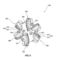
- FIG. 9 is a top elevation view of the rotary drill bit shown in FIG. 8 .
- Embodiments of the invention relate to non-cylindrical PDCs, and methods of fabricating such non-cylindrical PDCs without substantially undercutting a cemented carbide substrate thereof from an overlying PCD table bonded to the cemented carbide substrate.
- the non-cylindrical PDCs disclosed herein may be manufactured by forming a precursor PDC that comprises a PCD table including an upper surface and a table non-cylindrical lateral periphery, and a cemented carbide substrate bonded to the PCD table that includes a substrate non-cylindrical lateral periphery.
- the method may further include finish machining at least the substrate non-cylindrical lateral periphery of the precursor PDC to selected final machining dimensions.
- FIGS. 1A-3C described a number of different embodiments for fabricating a precursor non-cylindrical PDC that is, subsequently, subjected to finish machining.
- FIGS. 1A and 1B are isometric and cross-sectional views, respectively, of an assembly 100 to be HPHT processed to form a non-cylindrical PDC according to an embodiment.
- the assembly 100 includes a non-cylindrical cemented carbide substrate 102 including an interfacial surface 104 , an opposing back surface 106 , and a substrate non-cylindrical lateral periphery 108 extending therebetween.
- the interfacial surface 104 is depicted in FIGS. 1A and 1B as being substantially planar, in other embodiments, the interfacial surface 104 may exhibit a selected nonplanar topography.
- the cemented carbide substrate 102 may include, without limitation, cemented carbides, such as tungsten carbide, titanium carbide, chromium carbide, niobium carbide, tantalum carbide, vanadium carbide, or combinations thereof cemented with iron, nickel, cobalt, alloys thereof, or other suitable metal-solvent catalyst.
- the cemented carbide substrate 102 comprises cobalt-cemented tungsten carbide.
- the assembly 100 also includes a plurality of diamond particles 110 disposed adjacent to the interfacial surface 104 of the cemented carbide substrate 102 .
- the cemented carbide substrate 102 may include at least one alignment feature formed therein, such as a keyhole 112 configured to engage with a correspondingly configured key of a machining apparatus.
- the keyhole 112 may be positioned on the back surface 106 and along a central axis C of the cemented carbide substrate 102 defined by the periphery 108 thereof for ease of machining a PDC to be ultimately formed by HPHT processing the assembly 100 or in another suitable position on the cemented carbide substrate 102 .
- the cemented carbide substrate 102 may include at least one alignment feature extending therefrom, such as a key or projection 114 configured to engage with a correspondingly configured keyhole of a machining apparatus.
- the key 114 may be positioned on the back surface 106 and along a central axis C of the cemented carbide substrate 102 defined by the periphery 108 thereof for ease of machining or in another suitable position on the cemented carbide substrate 102 .
- the assembly 100 may be placed in a pressure transmitting medium, such as a refractory metal can embedded in pyrophyllite or other pressure transmitting medium.
- the pressure transmitting medium including the diamond particles 110 and the cemented carbide substrate 102 , may be subjected to an HPHT process using an ultra-high pressure press to create temperature and pressure conditions at which diamond is stable.
- the temperature of the HPHT process may be at least about 1000° C. (e.g., about 1200° C.
- the pressure of the HPHT process may be at least 4.0 GPa (e.g., about 5.0 GPa to about 8.0 GPa) for a time sufficient to infiltrate the diamond particles with a metal-solvent catalyst from the cemented carbide substrate 102 .
- the pressure of the HPHT process may be about 5 GPa to about 7 GPa and the temperature of the HPHT process may be about 1150° C. to about 1400° C. (e.g., about 1200° C. to about 1300° C.).
- the metal-solvent catalyst from the cemented carbide substrate 102 at least partially melts and infiltrates into interstitial regions between the diamond particles 110 to catalyze formation of PCD.
- the PCD comprises a plurality of directly bonded-together diamond grains that defines a PCD table 202 ( FIG. 2A ), with the infiltrated metal-solvent catalyst disposed in the interstitial regions defined by the diamond grains.
- the metal-solvent catalyst infiltrated into the diamond particles 110 forms a strong metallurgical bond between the PCD table 202 ( FIG. 2A ) and the cemented carbide substrate 102 .
- FIG. 2A is an isometric view of an embodiment of a precursor non-cylindrical PDC 200 formed by HPHT processing the assembly 100 shown in FIGS. 1A and 1B .
- the directly bonded-together diamond grains of the PCD table 202 exhibit diamond-to-diamond bonding (e.g., sp 3 bonding) therebetween.
- the infiltrated metal-solvent catalyst may be disposed in the interstitial regions defined by the bonded diamond grains.
- the PCD table 202 includes a working upper surface 204 , a generally opposing interfacial surface 206 that is bonded to the cemented carbide substrate 102 , and a table non-cylindrical lateral periphery 208 extending therebetween.
- the upper surface 204 is illustrated as being substantially planar, in other embodiments, the upper surface 204 may convex, concave, or another selected nonplanar geometry. It is noted that at least a portion of the periphery 208 may also function as a working surface that contacts a subterranean formation during drilling.
- At least one alignment feature may be formed as part of the PCD table 202 that is configured to facilitate alignment of the PDC 200 in a machining apparatus.
- the at least one alignment feature on the PCD table 202 may be a key or keyhole.
- the periphery 108 and periphery 208 are not defined by EDM. Consequently, the periphery 108 of the cemented carbide substrate 102 does not exhibit substantial undercutting that occurs when a cylindrical PDC is fabricated by EDM to form a non-cylindrical PDC.
- the cemented carbide substrate is preferentially removed at a greater rate than a PCD table so that an undercut of about 0.0010 inch to about 0.002 inch is formed depending upon EDM parameters, metal-solvent-catalyst content, and other factors.
- FIG. 2B which is an enlarged cross-sectional view of the PDC 200 , instead, the periphery 108 of the cemented carbide substrate 102 is not substantially undercut from the PCD table 202 .
- the periphery 108 of the cemented carbide substrate 102 may only be slightly undercut from the PCD table 202 by a distance W of less than about 0.0020 inch, such as about 0 inch to about 0.0020 inch, about 0.00050 inch to about 0.0020 inch, or about 0.0008 inch to about 0.0015 inch.
- W a distance W of less than about 0.0020 inch, such as about 0 inch to about 0.0020 inch, about 0.00050 inch to about 0.0020 inch, or about 0.0008 inch to about 0.0015 inch.
- the amount of undercutting is typically most significant at or near the interfacial surface 104 of the cemented carbide substrate 102 .
- the cementing constituent e.g., a cobalt
- the cementing constituent e.g., a cobalt
- the periphery 108 of the cemented carbide substrate 102 lacks a so-called “re-cast layer” formed by and characteristic of EDM processing.
- the cemented carbide substrate 102 and the PCD table 202 so-formed are illustrated in FIGS. 2A and 2B as being generally elliptical, with the periphery 108 and the periphery 208 defining a generally elliptical surface
- the cemented carbide substrate 102 and the PCD table 202 may exhibit a number of other non-cylindrical geometries, such as a wedge-shaped geometry, a rectangular geometry, a triangular geometry, a spline geometry, or another selected non-cylindrical geometry.
- FIG. 3A is an isometric view of a wedge-shaped PCD table 202 A according to an embodiment.
- a table periphery 208 A of the PCD table 202 A and a substrate periphery 108 A of cemented carbide substrate 102 A may define a wedge-shaped geometry. The corners of the wedge may be sharp, as illustrated, or filleted.
- FIG. 3B is an isometric view of a rectangular-shaped PCD table 202 B according to an embodiment.
- a table periphery 208 B of the PCD table 202 B and a substrate periphery 108 B of cemented carbide substrate 102 B may define a rectangle.
- the corners of the rectangle may be sharp, as illustrated, or filleted.
- FIG. 3C is an isometric view of a triangular-shaped PCD table 202 C according to an embodiment.
- a table periphery 208 C of the PCD table 202 C and a substrate periphery 108 C of cemented carbide substrate 102 C may define a triangle. The corners of the triangle may be sharp, as illustrated, or filleted.
- the diamond particles 110 are sintered under HPHT conditions to integrally form the PCD table 202 ( FIG. 2A ) with the cemented carbide substrate 102 .
- the diamond particles 110 may be replaced with an at least partially leached PCD table that may also exhibit any of the disclosed non-cylindrical geometries.
- Subjecting the at least partially leached PCD table and the cemented carbide substrate 102 to the HPHT process causes metal-solvent catalyst from the cemented carbide substrate 102 to at least partially infiltrate into and fill interstitial regions of the at least partially leached PCD table to form an infiltrated PCD table (i.e., a pre-sintered PCD table).
- an assembly 400 may be formed by positioning an at least partially leached PCD table 402 between the cemented carbide substrate 102 and a layer of infiltrant material 404 .
- the at least partially leached PCD table 402 includes an interfacial surface 406 positioned adjacent to the interfacial surface 104 of the cemented carbide substrate 102 , an upper surface 408 positioned adjacent to the layer of infiltrant material 404 , and a non-cylindrical lateral periphery 410 .
- the infiltrant material may infiltrate a first region 412 of the at least partially leached PCD table during HPHT processing prior to, after, or substantially simultaneous with the metal-solvent catalyst from the cemented carbide substrate 102 infiltrating into a second region 414 of the at least partially leached PCD table to form a PDC 416 .
- the infiltrant material may comprise silicon, a mixture of silicon and cobalt, a nonmetallic catalyst, or combinations of the foregoing.
- the nonmetallic catalyst may be selected from a carbonate (e.g., one or more carbonates of Li, Na, K, Be, Mg, Ca, Sr, and Ba), a sulfate (e.g., one or more sulfates of Be, Mg, Ca, Sr, and Ba), a hydroxide (e.g., one or more hydroxides of Be, Mg, Ca, Sr, and Ba), elemental phosphorous, a chloride (e.g., one or more chlorides of Li, Na, and K), elemental sulfur, a polycyclic aromatic hydrocarbon (e.g., naphthalene, anthracene, pentacene, perylene, coronene, or combinations of the foregoing) and/or a derivative thereof, a chlorinated hydrocarbon and/or a derivative thereof, a semiconductor material (e.g., germanium or a geranium alloy), and combinations of the foregoing.
- a carbonate e.
- one suitable carbonate catalyst is an alkali metal carbonate material including a mixture of sodium carbonate, lithium carbonate, and potassium carbonate that form a low-melting ternary eutectic system.
- This mixture and other suitable alkali metal carbonate materials are disclosed in U.S. patent application Ser. No. 12/185,457, which is incorporated herein, in its entirety, by this reference.
- the alkali metal carbonate material disposed in the interstitial regions of the first region may be partially or substantially completely converted to one or more corresponding alkali metal oxides by suitable heat treatment following infiltration.
- the infiltrant material 404 may be omitted and a metal-solvent catalyst from the cemented carbide substrate 102 (e.g., cobalt) or another source may infiltrate into and fill interstitial regions of the first region 412 and second region 414 of the at least partially leached PCD table 402 .
- the infiltration of the at least partially leached PCD table 402 with the metal-solvent catalyst may promote further nucleation and growth of diamond between existing diamond grains of the at least partially leached PCD table 402 .
- Such increased diamond-to-diamond bonding may enhance wear resistance and/or thermal stability of the infiltrated PCD table.
- the infiltrated PCD table may be subjected to a leaching process to remove the infiltrated metal-solvent catalyst from at least part of the first region 412 and/or at least part of the second region 414 .
- the at least partially leached PCD table 402 may be brazed to the cemented carbide substrate 102 .
- the at least partially leached PCD table 402 may be brazed to the cemented carbide substrate 102 brazed in a vacuum brazing process, an atmospheric brazing process, or an HPHT brazing process.
- the at least partially leached PCD table 402 may be fabricated by subjecting a plurality of diamond particles to an HPHT sintering process under diamond-stable conditions in the presence of the metallic catalyst (e.g., cobalt, nickel, iron, or alloys thereof) to facilitate intergrowth between the diamond particles and form a PCD body comprised of bonded diamond grains that exhibit diamond-to-diamond bonding therebetween.
- the metallic catalyst e.g., cobalt, nickel, iron, or alloys thereof
- the metallic catalyst may be mixed with the diamond particles or infiltrated from a metallic catalyst foil or powder adjacent to the diamond particles.
- the bonded diamond grains define interstitial regions, with the metallic catalyst disposed within the interstitial regions.
- the diamond particles may exhibit a single-mode diamond particle size distribution, or a bimodal or greater diamond particle size distribution.
- the as-sintered PCD body may be leached by immersion in an acid, such as aqua regia, nitric acid, hydrofluoric acid, mixtures of the foregoing, or subjected to another suitable process to remove at least a portion of the metallic catalyst from the interstitial regions of the PCD body and form the at least partially leached PCD table 402 .
- an acid such as aqua regia, nitric acid, hydrofluoric acid, mixtures of the foregoing
- the as-sintered PCD body may be immersed in the acid for about 2 to about 7 days (e.g., about 3, 5, or 7 days) or for a few weeks (e.g., about 4 weeks) depending on the process employed.
- the infiltrated metallic catalyst when the metallic catalyst is infiltrated into the diamond particles from a cemented tungsten carbide substrate including tungsten carbide particles cemented with a metallic catalyst (e.g., cobalt, nickel, iron, or alloys thereof), the infiltrated metallic catalyst may carry a tungsten-containing material (e.g., tungsten and/or tungsten carbide) therewith and the as-sintered PCD body may include such tungsten-containing material therein disposed interstitially between the bonded diamond grains.
- tungsten-containing material e.g., tungsten and/or tungsten carbide
- the as-sintered PCD body may include such tungsten-containing material therein disposed interstitially between the bonded diamond grains.
- at least a portion of the tungsten-containing material may not be substantially removed by the leaching process and may enhance the wear resistance of the at least partially leached PCD table.
- the at least partially leached PCD table 402 may be subjected to a shaping process after leaching, such as grinding or lapping, to tailor the non-cylindrical geometry thereof.
- the as-sintered PCD body may also be shaped prior to leaching by a machining process, such as electro-discharge machining.
- the diamond particles 110 may exhibit one or more selected sizes.
- the one or more selected sizes may be determined, for example, by passing the diamond particles through one or more sizing sieves or by any other method.
- the plurality of diamond particles may include a relatively larger size and at least one relatively smaller size.
- the phrases “relatively larger” and “relatively smaller” refer to particle sizes determined by any suitable method, which differ by at least a factor of two (e.g., 40 ⁇ m and 20 ⁇ m).
- the plurality of diamond particles may include a portion exhibiting a relatively larger size (e.g., 100 ⁇ m, 90 ⁇ m, 80 ⁇ m, 70 ⁇ m, 60 ⁇ m, 50 ⁇ m, 40 ⁇ m, 30 ⁇ m, 20 ⁇ m, 15 ⁇ m, 12 ⁇ m, 10 ⁇ m, 8 ⁇ m) and another portion exhibiting at least one relatively smaller size (e.g., 30 ⁇ m, 20 ⁇ m, 10 ⁇ m, 15 ⁇ m, 12 ⁇ m, 10 ⁇ m, 8 ⁇ m, 4 ⁇ m, 2 ⁇ m, 1 ⁇ m, 0.5 ⁇ m, less than 0.5 ⁇ m, 0.1 ⁇ m, less than 0.1 ⁇ m).
- a relatively larger size e.g., 100 ⁇ m, 90 ⁇ m, 80 ⁇ m, 70 ⁇ m, 60 ⁇ m, 50 ⁇ m, 40 ⁇ m, 30 ⁇ m, 20 ⁇ m, 15 ⁇ m, 12 ⁇ m, 10
- the plurality of diamond particles may include a portion exhibiting a relatively larger size between about 40 ⁇ m and about 15 ⁇ m and another portion exhibiting a relatively smaller size between about 12 ⁇ m and 2 ⁇ m.
- the plurality of diamond particles may also comprise three or more different sizes (e.g., one relatively larger size and two or more relatively smaller sizes) without limitation.
- FIGS. 5A and 5B illustrate a machining apparatus 500 and related process for finish machining any of the disclosed precursor non-cylindrical PDCs, such as the PDCs shown in FIGS. 2A, 3A-3C, and 4B .
- FIGS. 5A and 5B are schematic isometric and top plan views, respectively, of an embodiment of the machining apparatus 500 configured to perform finish machining on the precursor PDC shown in FIG. 2A .
- the machining apparatus 500 includes a jig portion 502 including at least one alignment feature 504 and a jig portion 506 .
- the jig portions 502 and 506 are movable relative to each other in axial directions A 1 and A 2 so that a precursor PDC 508 may be held securely therebetween.
- the precursor PDC 508 is used to represent any of the precursor non-cylindrical PDCs disclosed herein.
- the precursor PDC 508 includes a PCD table 510 bonded to a cemented carbide substrate 512 having at least one alignment feature 514 (e.g., a recess) configured to correspond to the geometry of the at least one alignment feature 504 on the jig portion 502 .
- the PCD table 510 has a table non-cylindrical periphery 511 and the cemented carbide substrate 512 has a substrate non-cylindrical periphery 513 .
- the jig portion 502 may having an abrasive surface instead of the at least one alignment feature 504 and the cemented carbide substrate 512 may lack the at least one alignment feature 514 or the at least one alignment feature 514 may be a visual alignment feature such as a marking.
- the machining apparatus 500 further includes a machining element, such as an abrasive grinding wheel 516 .
- a machining element such as an abrasive grinding wheel 516 .
- the abrasive grinding wheel may be a diamond-impregnated grinding wheel.
- a drive system 518 is operably coupled to the jig portions 502 and 506 .
- the drive system 518 is configured to rotate the jig portions 502 and 506 , with the precursor PDC 508 held therebetween, about a rotation axis R 1 .
- the at least one alignment feature 504 of the jig portion 502 and the at least one alignment feature 514 of the precursor PDC 508 are positioned so that a central axis C of the precursor PDC 508 is maintained in substantial alignment with the rotation axis R 1 .
- the at least one alignment feature 514 may be used to locate the central axis of the precursor PDC 508 .
- the drive system 518 is also operably coupled to the abrasive grinding wheel 516 .
- the drive system 518 is configured to rotate the abrasive grinding wheel 516 about a rotation axis R 2 and move the abrasive grinding wheel 516 in directions T 1 and T 2 .
- a control system 520 may be coupled to the drive system 518 that controls the operation thereof.
- one or both of the jig portions 502 and 506 are moved together to hold the precursor PDC 508 securely therebetween, with the central axis C of the precursor PDC 508 generally aligned with the rotation axis R 1 and the at least one alignment feature 514 of the PDC 508 in engagement with the at least one alignment feature of the jig portion 502 .
- the drive system 518 moves the abrasive grinding wheel 516 in the direction T 1 to engage the precursor PDC 508 .
- the drive system 518 may rotate the abrasive grinding wheel 516 about the rotation axis R 2 to machine the precursor PDC 508 to finish machining dimensions.
- the abrasive grinding wheel 516 may be rotatable a selected angle ⁇ ( FIG. 5B ) about an axis generally perpendicular to the rotation axes R 1 and R 2 so that a selected chamfer may be formed in the PCD table 510 of the PDC 508 .
- FIG. 6 is a cross-sectional view of the precursor PDC 508 overlying a finished non-cylindrical PDC 600 formed by machining, the precursor PDC 508 using the machining apparatus shown in FIGS. 5A and 5B .
- a thickness 602 of material from the PCD table 510 and the cemented carbide substrate 512 may be ground away by the abrasive grinding wheel 516 to form the finished non-cylindrical PDC 600 .
- the finished non-cylindrical PDC 600 includes a finished PCD table 510 ′ having a finished table non-cylindrical periphery 511 and a finished cemented carbide substrate 512 ′ having a finished substrate non-cylindrical periphery 513 ′.
- the thickness 602 removed from the precursor PDC 508 may be about 0.015 inch to about 0.080 inch, such as about 0.030 inch to about 0.060 inch.
- the finished non-cylindrical PDC 600 has the same general non-cylindrical configuration as the precursor PDC 508 except that a small amount of material (i.e., the thickness 602 of material) has been removed therefrom.
- the at least one alignment feature 514 FIG.
- the at least one alignment feature 514 may be removed in a separate grinding operation after forming the PDC 600 , if desired or necessary for a particular application.
- the at least one alignment feature 514 is not removed and, when structured as a keyhole, the at least one alignment feature 514 may function as a braze material reservoir for brazing the PDC 600 to a bit body of a drill bit.
- the undercutting is not substantial and may be less than about 0.0020 inch, such as about 0 inch to about 0.0020 inch, about 0.00050 inch to about 0.0020 inch or about 0.0008 inch to about 0.0015 inch.
- the extent of the undercutting may be dependent on the grain size and/or abrasion resistance of the finished PCD table 510 ′.
- a non-cylindrical lateral periphery 514 of the finished PCD table 510 ′ and a non-cylindrical lateral periphery 516 of the finished cemented carbide substrate 512 ′ may be finish machined so that they are tapered relative to an upper working surface 518 of the finished PCD table 510 ′.
- finish machining operations may be performed on the precursor PDC 508 as an alternative to or in addition to grinding using the machining apparatus 500 .
- finishing machining may be performed on the precursor PDC 508 using EDM, laser machining, honing, lapping, polishing, chemical-mechanical polishing, electrical discharge grinding, chemical/mechanical grinding, ultrasonic machining, or combinations of the foregoing.
- EDM finish machining is used, the EDM machining parameters and the thickness 602 of material to be removed are chosen to prevent substantial undercutting.
- finish machining operation may be omitted.
- the finishing operation may be eliminated, thereby reducing manufacturing cost and time.
- the finished PCD table 510 ′ of the finished non-cylindrical PDC 600 may be leached to remove the metal-solvent catalyst therefrom (when present) to a selected depth.
- the selected leaching depth may be about 5 ⁇ m to about 500 such as about 50 ⁇ m to about 100 ⁇ m.
- the leaching process may be performed on the PCD table 510 of the precursor PDC 508 prior to the final machining operation.
- a cylindrical PDC may be re-worked to different dimensions and/or geometry.
- one or more alignment features may be machined in a back surface of a cemented carbide substrate that carries a PCD table. The one or more alignment features may be used in conjunction with the jig portion 502 and the cylindrical PDC may be finished machined to a non-cylindrical geometry.
- a cylindrical PDC may be machined to an elliptical geometry.
- a precursor PDC may include one or more non-cylindrical PCD tables (e.g., one, two, or three non-cylindrical PCD tables) and a generally cylindrical cemented carbide substrate.
- FIGS. 7A and 7B are isometric and top plan views, respectively, of a precursor PDC 700 according to an embodiment.
- the precursor PDC 700 includes a non-cylindrical PCD table 702 having a non-cylindrical lateral periphery 703 .
- the PCD table 702 is bonded to a generally cylindrical cemented carbide substrate 704 in an HPHT process or by brazing.
- the PCD table 702 may be integrally formed with the cemented carbide substrate 704 in an HPHT process or may be an at least partially leached PCD table that is at least partially infiltrated with a constituent of the cemented carbide substrate 704 or a braze material.
- the PCD table 702 may exhibit any of the non-cylindrical geometries disclosed herein.
- the cemented carbide substrate 704 of the precursor PDC 700 may be subjected to a finish machining operation using, for example, the machining apparatus 500 shown in FIGS. 5A and 5B to remove excess material of the cemented carbide substrate 704 until a lateral periphery of the cemented carbide substrate 704 and the periphery 703 of the PCD table 702 are in substantial alignment, such as in the PDC 600 .
- FIG. 8 is an isometric view and FIG. 9 is a top elevation view of an embodiment of a rotary drill bit 800 that includes at least one non-cylindrical PDC configured according to any of the disclosed non-cylindrical PDC embodiments.
- the rotary drill bit 800 comprises a bit body 802 that includes radially and longitudinally extending blades 804 having leading faces 806 , and a threaded pin connection 808 for connecting the bit body 802 to a drilling string.
- the bit body 802 defines a leading end structure for drilling into a subterranean formation by rotation about a longitudinal axis 810 and application of weight-on-bit.
- At least one non-cylindrical PDC may be affixed to the bit body 802 .
- a plurality of PDCs 812 are secured to the blades 804 of the bit body 802 .
- each PDC 812 may include a PCD table 814 bonded to a substrate 816 .
- the PDCs 812 may comprise any finished non-cylindrical PDC disclosed herein, without limitation.
- a number of the PDCs 812 may be conventional in construction.
- circumferentially adjacent blades 804 define so-called junk slots 820 therebetween.
- the rotary drill bit 800 includes a plurality of nozzle cavities 818 for communicating drilling fluid from the interior of the rotary drill bit 800 to the PDCs 812 .
- FIGS. 8 and 9 merely depict one embodiment of a rotary drill bit that employs at least one non-cylindrical PDC fabricated and structured in accordance with the disclosed embodiments, without limitation.
- the rotary drill bit 800 is used to represent any number of earth-boring tools or drilling tools, including, for example, core bits, roller-cone bits, fixed-cutter bits, eccentric bits, bicenter bits, reamers, reamer wings, any other downhole tool including superabrasive compacts, or twist helical drills, without limitation.
- non-cylindrical PDCs disclosed herein may also be utilized in applications other than cutting technology.
- the disclosed non-cylindrical PDC embodiments may be used in wire dies, bearings, artificial joints, inserts, cutting elements, and heat sinks.
- any of the non-cylindrical PDCs disclosed herein may be employed in an article of manufacture including at least one superabrasive element or compact.
- non-cylindrical PDCs disclosed herein may be used in any apparatus or structure in which at least one conventional PDC is typically used.
- a rotor and a stator, assembled to form a thrust-bearing apparatus may each include one or more non-cylindrical PDCs (e.g., non-cylindrical PDC 600 of FIG. 6 ) configured according to any of the embodiments disclosed herein and may be operably assembled to a downhole drilling assembly.
- non-cylindrical PDCs e.g., non-cylindrical PDC 600 of FIG. 6
- non-cylindrical PDCs disclosed herein may also form all or part of heat sinks, wire dies, bearing elements, cutting elements, cutting inserts (e.g., on a roller-cone-type drill bit), machining inserts, or any other article of manufacture as known in the art.
- Other examples of articles of manufacture that may use any of the non-cylindrical PDCs disclosed herein are disclosed in U.S. Pat.
Abstract
Description
Claims (15)
Priority Applications (1)
| Application Number | Priority Date | Filing Date | Title |
|---|---|---|---|
| US12/558,939 US9770807B1 (en) | 2009-03-05 | 2009-09-14 | Non-cylindrical polycrystalline diamond compacts, methods of making same and applications therefor |
Applications Claiming Priority (2)
| Application Number | Priority Date | Filing Date | Title |
|---|---|---|---|
| US15761109P | 2009-03-05 | 2009-03-05 | |
| US12/558,939 US9770807B1 (en) | 2009-03-05 | 2009-09-14 | Non-cylindrical polycrystalline diamond compacts, methods of making same and applications therefor |
Publications (1)
| Publication Number | Publication Date |
|---|---|
| US9770807B1 true US9770807B1 (en) | 2017-09-26 |
Family
ID=51177796
Family Applications (2)
| Application Number | Title | Priority Date | Filing Date |
|---|---|---|---|
| US12/558,939 Active 2032-11-07 US9770807B1 (en) | 2009-03-05 | 2009-09-14 | Non-cylindrical polycrystalline diamond compacts, methods of making same and applications therefor |
| US12/717,158 Expired - Fee Related US8784517B1 (en) | 2009-03-05 | 2010-03-04 | Polycrystalline diamond compacts, methods of fabricating same, and applications therefor |
Family Applications After (1)
| Application Number | Title | Priority Date | Filing Date |
|---|---|---|---|
| US12/717,158 Expired - Fee Related US8784517B1 (en) | 2009-03-05 | 2010-03-04 | Polycrystalline diamond compacts, methods of fabricating same, and applications therefor |
Country Status (1)
| Country | Link |
|---|---|
| US (2) | US9770807B1 (en) |
Cited By (1)
| Publication number | Priority date | Publication date | Assignee | Title |
|---|---|---|---|---|
| CN111098236A (en) * | 2019-12-03 | 2020-05-05 | 惠州捷姆复合材料有限公司 | Molding process method of diamond sintered grinding wheel rod |
Families Citing this family (5)
| Publication number | Priority date | Publication date | Assignee | Title |
|---|---|---|---|---|
| US10309158B2 (en) | 2010-12-07 | 2019-06-04 | Us Synthetic Corporation | Method of partially infiltrating an at least partially leached polycrystalline diamond table and resultant polycrystalline diamond compacts |
| US9027675B1 (en) * | 2011-02-15 | 2015-05-12 | Us Synthetic Corporation | Polycrystalline diamond compact including a polycrystalline diamond table containing aluminum carbide therein and applications therefor |
| US10473154B2 (en) | 2015-08-26 | 2019-11-12 | Us Synthetic Corporation | Tilting pad bearing assemblies, and bearing apparatuses and methods of using the same |
| WO2018005310A1 (en) | 2016-06-28 | 2018-01-04 | Smith International, Inc. | Polycrystalline diamond constructions |
| WO2020131421A2 (en) * | 2018-12-17 | 2020-06-25 | Diamond Innovations, Inc. | Near net shape polycrystalline diamond cutters and methods of making thereof |
Citations (31)
| Publication number | Priority date | Publication date | Assignee | Title |
|---|---|---|---|---|
| US4268276A (en) | 1978-04-24 | 1981-05-19 | General Electric Company | Compact of boron-doped diamond and method for making same |
| US4274900A (en) | 1978-08-30 | 1981-06-23 | W. R. Grace & Co. | Multi-layer polyester/polyolefin shrink film |
| US4410054A (en) | 1981-12-03 | 1983-10-18 | Maurer Engineering Inc. | Well drilling tool with diamond radial/thrust bearings |
| US4468138A (en) | 1981-09-28 | 1984-08-28 | Maurer Engineering Inc. | Manufacture of diamond bearings |
| US4560014A (en) | 1982-04-05 | 1985-12-24 | Smith International, Inc. | Thrust bearing assembly for a downhole drill motor |
| US4629373A (en) * | 1983-06-22 | 1986-12-16 | Megadiamond Industries, Inc. | Polycrystalline diamond body with enhanced surface irregularities |
| US4646857A (en) * | 1985-10-24 | 1987-03-03 | Reed Tool Company | Means to secure cutting elements on drag type drill bits |
| US4664705A (en) | 1985-07-30 | 1987-05-12 | Sii Megadiamond, Inc. | Infiltrated thermally stable polycrystalline diamond |
| US4738322A (en) | 1984-12-21 | 1988-04-19 | Smith International Inc. | Polycrystalline diamond bearing system for a roller cone rock bit |
| US4811801A (en) | 1988-03-16 | 1989-03-14 | Smith International, Inc. | Rock bits and inserts therefor |
| US4913247A (en) | 1988-06-09 | 1990-04-03 | Eastman Christensen Company | Drill bit having improved cutter configuration |
| US5016718A (en) | 1989-01-26 | 1991-05-21 | Geir Tandberg | Combination drill bit |
| US5092687A (en) | 1991-06-04 | 1992-03-03 | Anadrill, Inc. | Diamond thrust bearing and method for manufacturing same |
| US5120327A (en) | 1991-03-05 | 1992-06-09 | Diamant-Boart Stratabit (Usa) Inc. | Cutting composite formed of cemented carbide substrate and diamond layer |
| US5135061A (en) | 1989-08-04 | 1992-08-04 | Newton Jr Thomas A | Cutting elements for rotary drill bits |
| WO1992014906A1 (en) | 1991-02-23 | 1992-09-03 | Brit Bit Limited | Improvements relating to drill bits |
| US5154245A (en) | 1990-04-19 | 1992-10-13 | Sandvik Ab | Diamond rock tools for percussive and rotary crushing rock drilling |
| US5180022A (en) | 1991-05-23 | 1993-01-19 | Brady William J | Rotary mining tools |
| US5364192A (en) | 1992-10-28 | 1994-11-15 | Damm Oliver F R A | Diamond bearing assembly |
| US5368398A (en) | 1992-10-28 | 1994-11-29 | Csir | Diamond bearing assembly |
| US5460233A (en) | 1993-03-30 | 1995-10-24 | Baker Hughes Incorporated | Diamond cutting structure for drilling hard subterranean formations |
| US5480233A (en) | 1994-10-14 | 1996-01-02 | Cunningham; James K. | Thrust bearing for use in downhole drilling systems |
| US5544713A (en) | 1993-08-17 | 1996-08-13 | Dennis Tool Company | Cutting element for drill bits |
| US5725413A (en) * | 1994-05-06 | 1998-03-10 | Board Of Trustees Of The University Of Arkansas | Apparatus for and method of polishing and planarizing polycrystalline diamonds, and polished and planarized polycrystalline diamonds and products made therefrom |
| US6521174B1 (en) * | 1999-01-13 | 2003-02-18 | Baker Hughes Incorporated | Method of forming polycrystalline diamond cutters having modified residual stresses |
| US6562462B2 (en) | 2000-09-20 | 2003-05-13 | Camco International (Uk) Limited | High volume density polycrystalline diamond with working surfaces depleted of catalyzing material |
| US6793681B1 (en) | 1994-08-12 | 2004-09-21 | Diamicron, Inc. | Prosthetic hip joint having a polycrystalline diamond articulation surface and a plurality of substrate layers |
| US20080023230A1 (en) * | 2006-07-28 | 2008-01-31 | Hyun Sam Cho | Polycrystalline superabrasive composite tools and methods of forming the same |
| US7493973B2 (en) | 2005-05-26 | 2009-02-24 | Smith International, Inc. | Polycrystalline diamond materials having improved abrasion resistance, thermal stability and impact resistance |
| US20090173015A1 (en) | 2007-02-06 | 2009-07-09 | Smith International, Inc. | Polycrystalline Diamond Constructions Having Improved Thermal Stability |
| US8236074B1 (en) | 2006-10-10 | 2012-08-07 | Us Synthetic Corporation | Superabrasive elements, methods of manufacturing, and drill bits including same |
-
2009
- 2009-09-14 US US12/558,939 patent/US9770807B1/en active Active
-
2010
- 2010-03-04 US US12/717,158 patent/US8784517B1/en not_active Expired - Fee Related
Patent Citations (32)
| Publication number | Priority date | Publication date | Assignee | Title |
|---|---|---|---|---|
| US4268276A (en) | 1978-04-24 | 1981-05-19 | General Electric Company | Compact of boron-doped diamond and method for making same |
| US4274900A (en) | 1978-08-30 | 1981-06-23 | W. R. Grace & Co. | Multi-layer polyester/polyolefin shrink film |
| US4468138A (en) | 1981-09-28 | 1984-08-28 | Maurer Engineering Inc. | Manufacture of diamond bearings |
| US4410054A (en) | 1981-12-03 | 1983-10-18 | Maurer Engineering Inc. | Well drilling tool with diamond radial/thrust bearings |
| US4560014A (en) | 1982-04-05 | 1985-12-24 | Smith International, Inc. | Thrust bearing assembly for a downhole drill motor |
| US4629373A (en) * | 1983-06-22 | 1986-12-16 | Megadiamond Industries, Inc. | Polycrystalline diamond body with enhanced surface irregularities |
| US4738322A (en) | 1984-12-21 | 1988-04-19 | Smith International Inc. | Polycrystalline diamond bearing system for a roller cone rock bit |
| US4664705A (en) | 1985-07-30 | 1987-05-12 | Sii Megadiamond, Inc. | Infiltrated thermally stable polycrystalline diamond |
| US4646857A (en) * | 1985-10-24 | 1987-03-03 | Reed Tool Company | Means to secure cutting elements on drag type drill bits |
| US4811801A (en) | 1988-03-16 | 1989-03-14 | Smith International, Inc. | Rock bits and inserts therefor |
| US4913247A (en) | 1988-06-09 | 1990-04-03 | Eastman Christensen Company | Drill bit having improved cutter configuration |
| US5016718A (en) | 1989-01-26 | 1991-05-21 | Geir Tandberg | Combination drill bit |
| US5135061A (en) | 1989-08-04 | 1992-08-04 | Newton Jr Thomas A | Cutting elements for rotary drill bits |
| US5154245A (en) | 1990-04-19 | 1992-10-13 | Sandvik Ab | Diamond rock tools for percussive and rotary crushing rock drilling |
| WO1992014906A1 (en) | 1991-02-23 | 1992-09-03 | Brit Bit Limited | Improvements relating to drill bits |
| US5120327A (en) | 1991-03-05 | 1992-06-09 | Diamant-Boart Stratabit (Usa) Inc. | Cutting composite formed of cemented carbide substrate and diamond layer |
| US5180022A (en) | 1991-05-23 | 1993-01-19 | Brady William J | Rotary mining tools |
| US5092687A (en) | 1991-06-04 | 1992-03-03 | Anadrill, Inc. | Diamond thrust bearing and method for manufacturing same |
| US5364192A (en) | 1992-10-28 | 1994-11-15 | Damm Oliver F R A | Diamond bearing assembly |
| US5368398A (en) | 1992-10-28 | 1994-11-29 | Csir | Diamond bearing assembly |
| US5460233A (en) | 1993-03-30 | 1995-10-24 | Baker Hughes Incorporated | Diamond cutting structure for drilling hard subterranean formations |
| US5544713A (en) | 1993-08-17 | 1996-08-13 | Dennis Tool Company | Cutting element for drill bits |
| US5725413A (en) * | 1994-05-06 | 1998-03-10 | Board Of Trustees Of The University Of Arkansas | Apparatus for and method of polishing and planarizing polycrystalline diamonds, and polished and planarized polycrystalline diamonds and products made therefrom |
| US6793681B1 (en) | 1994-08-12 | 2004-09-21 | Diamicron, Inc. | Prosthetic hip joint having a polycrystalline diamond articulation surface and a plurality of substrate layers |
| US5480233A (en) | 1994-10-14 | 1996-01-02 | Cunningham; James K. | Thrust bearing for use in downhole drilling systems |
| US6521174B1 (en) * | 1999-01-13 | 2003-02-18 | Baker Hughes Incorporated | Method of forming polycrystalline diamond cutters having modified residual stresses |
| US6562462B2 (en) | 2000-09-20 | 2003-05-13 | Camco International (Uk) Limited | High volume density polycrystalline diamond with working surfaces depleted of catalyzing material |
| US6749033B2 (en) | 2000-09-20 | 2004-06-15 | Reedhyoalog (Uk) Limited | Polycrystalline diamond partially depleted of catalyzing material |
| US7493973B2 (en) | 2005-05-26 | 2009-02-24 | Smith International, Inc. | Polycrystalline diamond materials having improved abrasion resistance, thermal stability and impact resistance |
| US20080023230A1 (en) * | 2006-07-28 | 2008-01-31 | Hyun Sam Cho | Polycrystalline superabrasive composite tools and methods of forming the same |
| US8236074B1 (en) | 2006-10-10 | 2012-08-07 | Us Synthetic Corporation | Superabrasive elements, methods of manufacturing, and drill bits including same |
| US20090173015A1 (en) | 2007-02-06 | 2009-07-09 | Smith International, Inc. | Polycrystalline Diamond Constructions Having Improved Thermal Stability |
Non-Patent Citations (13)
| Title |
|---|
| U.S. Appl. No. 12/717,158, Apr. 6, 2012, Office Action. |
| U.S. Appl. No. 12/717,158, Aug. 28, 2013, Office Action. |
| U.S. Appl. No. 12/717,158, Jul. 19, 2012, Office Action. |
| U.S. Appl. No. 12/717,158, Jul. 2, 2014, Issue Notification. |
| U.S. Appl. No. 12/717,158, Mar. 1, 2013, Office Action. |
| U.S. Appl. No. 12/717,158, Mar. 20, 2014, Notice of Allowance. |
| U.S. Appl. No. 12/717,158, Mar. 26, 2014, Notice of Allowability. |
| U.S. Appl. No. 12/717,158, Mar. 4, 2010, Gonzalez et al. |
| U.S. Appl. No. 14/307,835, Dec. 2, 2015, Office Action. |
| U.S. Appl. No. 14/307,835, Jun. 18, 2014, Gonzalez et al. |
| U.S. Appl. No. 14/307,835, Mar. 1, 2016, Office Action. |
| U.S. Appl. No. 61/157,611, Mar. 5, 2009, Gonzalez. |
| Vail et al., U.S. Appl. No. 12/185,457, "Methods of Fabricating Polycrystalline Diamond With a Carbonate Material Including at Least One Alkali Metal Carbonate, Polycrystalline Diamond So-Formed, and Applications Therefor" filed Aug. 4, 2008. |
Cited By (2)
| Publication number | Priority date | Publication date | Assignee | Title |
|---|---|---|---|---|
| CN111098236A (en) * | 2019-12-03 | 2020-05-05 | 惠州捷姆复合材料有限公司 | Molding process method of diamond sintered grinding wheel rod |
| CN111098236B (en) * | 2019-12-03 | 2022-02-08 | 惠州捷姆复合材料有限公司 | Molding process method of diamond sintered grinding wheel rod |
Also Published As
| Publication number | Publication date |
|---|---|
| US8784517B1 (en) | 2014-07-22 |
Similar Documents
| Publication | Publication Date | Title |
|---|---|---|
| US11141834B2 (en) | Polycrystalline diamond compacts and related methods | |
| US10920499B1 (en) | Polycrystalline diamond compact including a non-uniformly leached polycrystalline diamond table and applications therefor | |
| US20190242193A1 (en) | Polycrystalline diamond compacts | |
| US11773654B1 (en) | Polycrystalline diamond compacts, methods of making same, and applications therefor | |
| US9808910B2 (en) | Polycrystalline diamond compacts | |
| US9376868B1 (en) | Polycrystalline diamond compact including pre-sintered polycrystalline diamond table having a thermally-stable region and applications therefor | |
| US8146687B1 (en) | Polycrystalline diamond compact including at least one thermally-stable polycrystalline diamond body and applications therefor | |
| US9657529B1 (en) | Polycrystalline diamond compact including a pre-sintered polycrystalline diamond table including a nonmetallic catalyst that limits infiltration of a metallic-catalyst infiltrant therein and applications therefor | |
| US9404310B1 (en) | Polycrystalline diamond compacts including a domed polycrystalline diamond table, and applications therefor | |
| US8230953B1 (en) | Polycrystalline diamond compacts and drill bits using same | |
| US8216677B2 (en) | Polycrystalline diamond compacts, methods of making same, and applications therefor | |
| US8881361B1 (en) | Methods of repairing a rotary drill bit | |
| US20140338985A1 (en) | Polycrystalline diamond compact including a substrate having a raised interfacial surface bonded to a polycrystalline diamond table, and applications therefor | |
| US8702824B1 (en) | Polycrystalline diamond compact including a polycrystalline diamond table fabricated with one or more sp2-carbon-containing additives to enhance cutting lip formation, and related methods and applications | |
| US10119334B1 (en) | Polycrystalline diamond compact including substantially single-phase polycrystalline diamond body and applications therefor | |
| US9770807B1 (en) | Non-cylindrical polycrystalline diamond compacts, methods of making same and applications therefor | |
| US11180961B1 (en) | Multi-part superabrasive compacts, rotary drill bits including multi-part superabrasive compacts, and related methods |
Legal Events
| Date | Code | Title | Description |
|---|---|---|---|
| AS | Assignment |
Owner name: US SYNTHETIC CORPORATION, UTAH Free format text: ASSIGNMENT OF ASSIGNORS INTEREST;ASSIGNORS:MIESS, DAVID P.;CHAPMAN, MARK P.;CHOATE, STEVEN L.;AND OTHERS;REEL/FRAME:023227/0013 Effective date: 20090910 |
|
| AS | Assignment |
Owner name: US SYNTHETIC CORPORATION, UTAH Free format text: ASSIGNMENT OF ASSIGNORS INTEREST;ASSIGNORS:MIESS, DAVID P.;CHAPMAN, MARK P.;CHOATE, STEVEN L.;AND OTHERS;SIGNING DATES FROM 20100218 TO 20100219;REEL/FRAME:023968/0819 |
|
| STCF | Information on status: patent grant |
Free format text: PATENTED CASE |
|
| AS | Assignment |
Owner name: JPMORGAN CHASE BANK, N.A., NEW YORK Free format text: SECURITY AGREEMENT;ASSIGNORS:APERGY (DELAWARE) FORMATION, INC.;APERGY BMCS ACQUISITION CORP.;APERGY ENERGY AUTOMATION, LLC;AND OTHERS;REEL/FRAME:046117/0015 Effective date: 20180509 |
|
| AS | Assignment |
Owner name: BANK OF AMERICA, N.A., NORTH CAROLINA Free format text: SECURITY INTEREST;ASSIGNORS:ACE DOWNHOLE, LLC;APERGY BMCS ACQUISITION CORP.;HARBISON-FISCHER, INC.;AND OTHERS;REEL/FRAME:053790/0001 Effective date: 20200603 |
|
| MAFP | Maintenance fee payment |
Free format text: PAYMENT OF MAINTENANCE FEE, 4TH YEAR, LARGE ENTITY (ORIGINAL EVENT CODE: M1551); ENTITY STATUS OF PATENT OWNER: LARGE ENTITY Year of fee payment: 4 |
|
| AS | Assignment |
Owner name: WINDROCK, INC., TEXAS Free format text: RELEASE BY SECURED PARTY;ASSIGNOR:BANK OF AMERICA, N.A.;REEL/FRAME:060305/0001 Effective date: 20220607 Owner name: US SYNTHETIC CORPORATION, TEXAS Free format text: RELEASE BY SECURED PARTY;ASSIGNOR:BANK OF AMERICA, N.A.;REEL/FRAME:060305/0001 Effective date: 20220607 Owner name: NORRISEAL-WELLMARK, INC., TEXAS Free format text: RELEASE BY SECURED PARTY;ASSIGNOR:BANK OF AMERICA, N.A.;REEL/FRAME:060305/0001 Effective date: 20220607 Owner name: APERGY BMCS ACQUISITION CORP., TEXAS Free format text: RELEASE BY SECURED PARTY;ASSIGNOR:BANK OF AMERICA, N.A.;REEL/FRAME:060305/0001 Effective date: 20220607 Owner name: THETA OILFIELD SERVICES, INC., TEXAS Free format text: RELEASE BY SECURED PARTY;ASSIGNOR:BANK OF AMERICA, N.A.;REEL/FRAME:060305/0001 Effective date: 20220607 Owner name: SPIRIT GLOBAL ENERGY SOLUTIONS, INC., TEXAS Free format text: RELEASE BY SECURED PARTY;ASSIGNOR:BANK OF AMERICA, N.A.;REEL/FRAME:060305/0001 Effective date: 20220607 Owner name: QUARTZDYNE, INC., TEXAS Free format text: RELEASE BY SECURED PARTY;ASSIGNOR:BANK OF AMERICA, N.A.;REEL/FRAME:060305/0001 Effective date: 20220607 Owner name: PCS FERGUSON, INC., TEXAS Free format text: RELEASE BY SECURED PARTY;ASSIGNOR:BANK OF AMERICA, N.A.;REEL/FRAME:060305/0001 Effective date: 20220607 Owner name: NORRIS RODS, INC., TEXAS Free format text: RELEASE BY SECURED PARTY;ASSIGNOR:BANK OF AMERICA, N.A.;REEL/FRAME:060305/0001 Effective date: 20220607 Owner name: HARBISON-FISCHER, INC., TEXAS Free format text: RELEASE BY SECURED PARTY;ASSIGNOR:BANK OF AMERICA, N.A.;REEL/FRAME:060305/0001 Effective date: 20220607 Owner name: ACE DOWNHOLE, LLC, TEXAS Free format text: RELEASE BY SECURED PARTY;ASSIGNOR:BANK OF AMERICA, N.A.;REEL/FRAME:060305/0001 Effective date: 20220607 |