US9776155B1 - Hydrocarbon vapor recovery system with oxygen reduction - Google Patents
Hydrocarbon vapor recovery system with oxygen reduction Download PDFInfo
- Publication number
- US9776155B1 US9776155B1 US14/678,336 US201514678336A US9776155B1 US 9776155 B1 US9776155 B1 US 9776155B1 US 201514678336 A US201514678336 A US 201514678336A US 9776155 B1 US9776155 B1 US 9776155B1
- Authority
- US
- United States
- Prior art keywords
- gas
- vessel
- heated vapor
- vapors
- inlet
- Prior art date
- Legal status (The legal status is an assumption and is not a legal conclusion. Google has not performed a legal analysis and makes no representation as to the accuracy of the status listed.)
- Active
Links
Images


Classifications
-
- B—PERFORMING OPERATIONS; TRANSPORTING
- B01—PHYSICAL OR CHEMICAL PROCESSES OR APPARATUS IN GENERAL
- B01J—CHEMICAL OR PHYSICAL PROCESSES, e.g. CATALYSIS OR COLLOID CHEMISTRY; THEIR RELEVANT APPARATUS
- B01J8/00—Chemical or physical processes in general, conducted in the presence of fluids and solid particles; Apparatus for such processes
- B01J8/02—Chemical or physical processes in general, conducted in the presence of fluids and solid particles; Apparatus for such processes with stationary particles, e.g. in fixed beds
- B01J8/0278—Feeding reactive fluids
-
- B—PERFORMING OPERATIONS; TRANSPORTING
- B01—PHYSICAL OR CHEMICAL PROCESSES OR APPARATUS IN GENERAL
- B01J—CHEMICAL OR PHYSICAL PROCESSES, e.g. CATALYSIS OR COLLOID CHEMISTRY; THEIR RELEVANT APPARATUS
- B01J8/00—Chemical or physical processes in general, conducted in the presence of fluids and solid particles; Apparatus for such processes
- B01J8/001—Controlling catalytic processes
-
- B—PERFORMING OPERATIONS; TRANSPORTING
- B01—PHYSICAL OR CHEMICAL PROCESSES OR APPARATUS IN GENERAL
- B01J—CHEMICAL OR PHYSICAL PROCESSES, e.g. CATALYSIS OR COLLOID CHEMISTRY; THEIR RELEVANT APPARATUS
- B01J8/00—Chemical or physical processes in general, conducted in the presence of fluids and solid particles; Apparatus for such processes
- B01J8/02—Chemical or physical processes in general, conducted in the presence of fluids and solid particles; Apparatus for such processes with stationary particles, e.g. in fixed beds
- B01J8/0242—Chemical or physical processes in general, conducted in the presence of fluids and solid particles; Apparatus for such processes with stationary particles, e.g. in fixed beds the fluid flow within the bed being predominantly vertical
- B01J8/025—Chemical or physical processes in general, conducted in the presence of fluids and solid particles; Apparatus for such processes with stationary particles, e.g. in fixed beds the fluid flow within the bed being predominantly vertical in a cylindrical shaped bed
-
- B—PERFORMING OPERATIONS; TRANSPORTING
- B01—PHYSICAL OR CHEMICAL PROCESSES OR APPARATUS IN GENERAL
- B01J—CHEMICAL OR PHYSICAL PROCESSES, e.g. CATALYSIS OR COLLOID CHEMISTRY; THEIR RELEVANT APPARATUS
- B01J8/00—Chemical or physical processes in general, conducted in the presence of fluids and solid particles; Apparatus for such processes
- B01J8/02—Chemical or physical processes in general, conducted in the presence of fluids and solid particles; Apparatus for such processes with stationary particles, e.g. in fixed beds
- B01J8/0285—Heating or cooling the reactor
-
- B—PERFORMING OPERATIONS; TRANSPORTING
- B01—PHYSICAL OR CHEMICAL PROCESSES OR APPARATUS IN GENERAL
- B01J—CHEMICAL OR PHYSICAL PROCESSES, e.g. CATALYSIS OR COLLOID CHEMISTRY; THEIR RELEVANT APPARATUS
- B01J8/00—Chemical or physical processes in general, conducted in the presence of fluids and solid particles; Apparatus for such processes
- B01J8/02—Chemical or physical processes in general, conducted in the presence of fluids and solid particles; Apparatus for such processes with stationary particles, e.g. in fixed beds
- B01J8/04—Chemical or physical processes in general, conducted in the presence of fluids and solid particles; Apparatus for such processes with stationary particles, e.g. in fixed beds the fluid passing successively through two or more beds
- B01J8/0446—Chemical or physical processes in general, conducted in the presence of fluids and solid particles; Apparatus for such processes with stationary particles, e.g. in fixed beds the fluid passing successively through two or more beds the flow within the beds being predominantly vertical
- B01J8/0449—Chemical or physical processes in general, conducted in the presence of fluids and solid particles; Apparatus for such processes with stationary particles, e.g. in fixed beds the fluid passing successively through two or more beds the flow within the beds being predominantly vertical in two or more cylindrical beds
- B01J8/0453—Chemical or physical processes in general, conducted in the presence of fluids and solid particles; Apparatus for such processes with stationary particles, e.g. in fixed beds the fluid passing successively through two or more beds the flow within the beds being predominantly vertical in two or more cylindrical beds the beds being superimposed one above the other
-
- B—PERFORMING OPERATIONS; TRANSPORTING
- B01—PHYSICAL OR CHEMICAL PROCESSES OR APPARATUS IN GENERAL
- B01J—CHEMICAL OR PHYSICAL PROCESSES, e.g. CATALYSIS OR COLLOID CHEMISTRY; THEIR RELEVANT APPARATUS
- B01J8/00—Chemical or physical processes in general, conducted in the presence of fluids and solid particles; Apparatus for such processes
- B01J8/02—Chemical or physical processes in general, conducted in the presence of fluids and solid particles; Apparatus for such processes with stationary particles, e.g. in fixed beds
- B01J8/04—Chemical or physical processes in general, conducted in the presence of fluids and solid particles; Apparatus for such processes with stationary particles, e.g. in fixed beds the fluid passing successively through two or more beds
- B01J8/0446—Chemical or physical processes in general, conducted in the presence of fluids and solid particles; Apparatus for such processes with stationary particles, e.g. in fixed beds the fluid passing successively through two or more beds the flow within the beds being predominantly vertical
- B01J8/0449—Chemical or physical processes in general, conducted in the presence of fluids and solid particles; Apparatus for such processes with stationary particles, e.g. in fixed beds the fluid passing successively through two or more beds the flow within the beds being predominantly vertical in two or more cylindrical beds
- B01J8/0457—Chemical or physical processes in general, conducted in the presence of fluids and solid particles; Apparatus for such processes with stationary particles, e.g. in fixed beds the fluid passing successively through two or more beds the flow within the beds being predominantly vertical in two or more cylindrical beds the beds being placed in separate reactors
-
- B—PERFORMING OPERATIONS; TRANSPORTING
- B01—PHYSICAL OR CHEMICAL PROCESSES OR APPARATUS IN GENERAL
- B01J—CHEMICAL OR PHYSICAL PROCESSES, e.g. CATALYSIS OR COLLOID CHEMISTRY; THEIR RELEVANT APPARATUS
- B01J8/00—Chemical or physical processes in general, conducted in the presence of fluids and solid particles; Apparatus for such processes
- B01J8/02—Chemical or physical processes in general, conducted in the presence of fluids and solid particles; Apparatus for such processes with stationary particles, e.g. in fixed beds
- B01J8/04—Chemical or physical processes in general, conducted in the presence of fluids and solid particles; Apparatus for such processes with stationary particles, e.g. in fixed beds the fluid passing successively through two or more beds
- B01J8/0492—Feeding reactive fluids
-
- B—PERFORMING OPERATIONS; TRANSPORTING
- B01—PHYSICAL OR CHEMICAL PROCESSES OR APPARATUS IN GENERAL
- B01J—CHEMICAL OR PHYSICAL PROCESSES, e.g. CATALYSIS OR COLLOID CHEMISTRY; THEIR RELEVANT APPARATUS
- B01J8/00—Chemical or physical processes in general, conducted in the presence of fluids and solid particles; Apparatus for such processes
- B01J8/02—Chemical or physical processes in general, conducted in the presence of fluids and solid particles; Apparatus for such processes with stationary particles, e.g. in fixed beds
- B01J8/04—Chemical or physical processes in general, conducted in the presence of fluids and solid particles; Apparatus for such processes with stationary particles, e.g. in fixed beds the fluid passing successively through two or more beds
- B01J8/0496—Heating or cooling the reactor
-
- B—PERFORMING OPERATIONS; TRANSPORTING
- B01—PHYSICAL OR CHEMICAL PROCESSES OR APPARATUS IN GENERAL
- B01J—CHEMICAL OR PHYSICAL PROCESSES, e.g. CATALYSIS OR COLLOID CHEMISTRY; THEIR RELEVANT APPARATUS
- B01J2208/00—Processes carried out in the presence of solid particles; Reactors therefor
- B01J2208/00008—Controlling the process
- B01J2208/00017—Controlling the temperature
- B01J2208/00026—Controlling or regulating the heat exchange system
- B01J2208/00035—Controlling or regulating the heat exchange system involving measured parameters
- B01J2208/00044—Temperature measurement
- B01J2208/00061—Temperature measurement of the reactants
-
- B—PERFORMING OPERATIONS; TRANSPORTING
- B01—PHYSICAL OR CHEMICAL PROCESSES OR APPARATUS IN GENERAL
- B01J—CHEMICAL OR PHYSICAL PROCESSES, e.g. CATALYSIS OR COLLOID CHEMISTRY; THEIR RELEVANT APPARATUS
- B01J2208/00—Processes carried out in the presence of solid particles; Reactors therefor
- B01J2208/00008—Controlling the process
- B01J2208/00017—Controlling the temperature
- B01J2208/00026—Controlling or regulating the heat exchange system
- B01J2208/00035—Controlling or regulating the heat exchange system involving measured parameters
- B01J2208/0007—Pressure measurement
-
- B—PERFORMING OPERATIONS; TRANSPORTING
- B01—PHYSICAL OR CHEMICAL PROCESSES OR APPARATUS IN GENERAL
- B01J—CHEMICAL OR PHYSICAL PROCESSES, e.g. CATALYSIS OR COLLOID CHEMISTRY; THEIR RELEVANT APPARATUS
- B01J2208/00—Processes carried out in the presence of solid particles; Reactors therefor
- B01J2208/00008—Controlling the process
- B01J2208/00017—Controlling the temperature
- B01J2208/00106—Controlling the temperature by indirect heat exchange
- B01J2208/00168—Controlling the temperature by indirect heat exchange with heat exchange elements outside the bed of solid particles
- B01J2208/00176—Controlling the temperature by indirect heat exchange with heat exchange elements outside the bed of solid particles outside the reactor
-
- B—PERFORMING OPERATIONS; TRANSPORTING
- B01—PHYSICAL OR CHEMICAL PROCESSES OR APPARATUS IN GENERAL
- B01J—CHEMICAL OR PHYSICAL PROCESSES, e.g. CATALYSIS OR COLLOID CHEMISTRY; THEIR RELEVANT APPARATUS
- B01J2208/00—Processes carried out in the presence of solid particles; Reactors therefor
- B01J2208/00008—Controlling the process
- B01J2208/00017—Controlling the temperature
- B01J2208/00106—Controlling the temperature by indirect heat exchange
- B01J2208/00265—Part of all of the reactants being heated or cooled outside the reactor while recycling
- B01J2208/00274—Part of all of the reactants being heated or cooled outside the reactor while recycling involving reactant vapours
-
- B—PERFORMING OPERATIONS; TRANSPORTING
- B01—PHYSICAL OR CHEMICAL PROCESSES OR APPARATUS IN GENERAL
- B01J—CHEMICAL OR PHYSICAL PROCESSES, e.g. CATALYSIS OR COLLOID CHEMISTRY; THEIR RELEVANT APPARATUS
- B01J2208/00—Processes carried out in the presence of solid particles; Reactors therefor
- B01J2208/00008—Controlling the process
- B01J2208/00017—Controlling the temperature
- B01J2208/0053—Controlling multiple zones along the direction of flow, e.g. pre-heating and after-cooling
-
- B—PERFORMING OPERATIONS; TRANSPORTING
- B01—PHYSICAL OR CHEMICAL PROCESSES OR APPARATUS IN GENERAL
- B01J—CHEMICAL OR PHYSICAL PROCESSES, e.g. CATALYSIS OR COLLOID CHEMISTRY; THEIR RELEVANT APPARATUS
- B01J2208/00—Processes carried out in the presence of solid particles; Reactors therefor
- B01J2208/00008—Controlling the process
- B01J2208/00548—Flow
-
- B—PERFORMING OPERATIONS; TRANSPORTING
- B01—PHYSICAL OR CHEMICAL PROCESSES OR APPARATUS IN GENERAL
- B01J—CHEMICAL OR PHYSICAL PROCESSES, e.g. CATALYSIS OR COLLOID CHEMISTRY; THEIR RELEVANT APPARATUS
- B01J2208/00—Processes carried out in the presence of solid particles; Reactors therefor
- B01J2208/02—Processes carried out in the presence of solid particles; Reactors therefor with stationary particles
- B01J2208/023—Details
- B01J2208/024—Particulate material
- B01J2208/025—Two or more types of catalyst
-
- B—PERFORMING OPERATIONS; TRANSPORTING
- B01—PHYSICAL OR CHEMICAL PROCESSES OR APPARATUS IN GENERAL
- B01J—CHEMICAL OR PHYSICAL PROCESSES, e.g. CATALYSIS OR COLLOID CHEMISTRY; THEIR RELEVANT APPARATUS
- B01J2208/00—Processes carried out in the presence of solid particles; Reactors therefor
- B01J2208/02—Processes carried out in the presence of solid particles; Reactors therefor with stationary particles
- B01J2208/023—Details
- B01J2208/027—Beds
-
- B—PERFORMING OPERATIONS; TRANSPORTING
- B01—PHYSICAL OR CHEMICAL PROCESSES OR APPARATUS IN GENERAL
- B01J—CHEMICAL OR PHYSICAL PROCESSES, e.g. CATALYSIS OR COLLOID CHEMISTRY; THEIR RELEVANT APPARATUS
- B01J2219/00—Chemical, physical or physico-chemical processes in general; Their relevant apparatus
- B01J2219/00049—Controlling or regulating processes
- B01J2219/00191—Control algorithm
- B01J2219/00193—Sensing a parameter
- B01J2219/00195—Sensing a parameter of the reaction system
- B01J2219/00198—Sensing a parameter of the reaction system at the reactor inlet
-
- B—PERFORMING OPERATIONS; TRANSPORTING
- B01—PHYSICAL OR CHEMICAL PROCESSES OR APPARATUS IN GENERAL
- B01J—CHEMICAL OR PHYSICAL PROCESSES, e.g. CATALYSIS OR COLLOID CHEMISTRY; THEIR RELEVANT APPARATUS
- B01J2219/00—Chemical, physical or physico-chemical processes in general; Their relevant apparatus
- B01J2219/00049—Controlling or regulating processes
- B01J2219/00191—Control algorithm
- B01J2219/00193—Sensing a parameter
- B01J2219/00195—Sensing a parameter of the reaction system
- B01J2219/00202—Sensing a parameter of the reaction system at the reactor outlet
-
- B—PERFORMING OPERATIONS; TRANSPORTING
- B01—PHYSICAL OR CHEMICAL PROCESSES OR APPARATUS IN GENERAL
- B01J—CHEMICAL OR PHYSICAL PROCESSES, e.g. CATALYSIS OR COLLOID CHEMISTRY; THEIR RELEVANT APPARATUS
- B01J2219/00—Chemical, physical or physico-chemical processes in general; Their relevant apparatus
- B01J2219/00049—Controlling or regulating processes
- B01J2219/00191—Control algorithm
- B01J2219/00211—Control algorithm comparing a sensed parameter with a pre-set value
- B01J2219/00213—Fixed parameter value
-
- B—PERFORMING OPERATIONS; TRANSPORTING
- B01—PHYSICAL OR CHEMICAL PROCESSES OR APPARATUS IN GENERAL
- B01J—CHEMICAL OR PHYSICAL PROCESSES, e.g. CATALYSIS OR COLLOID CHEMISTRY; THEIR RELEVANT APPARATUS
- B01J2219/00—Chemical, physical or physico-chemical processes in general; Their relevant apparatus
- B01J2219/00049—Controlling or regulating processes
- B01J2219/00191—Control algorithm
- B01J2219/00222—Control algorithm taking actions
- B01J2219/00227—Control algorithm taking actions modifying the operating conditions
- B01J2219/00229—Control algorithm taking actions modifying the operating conditions of the reaction system
- B01J2219/00231—Control algorithm taking actions modifying the operating conditions of the reaction system at the reactor inlet
-
- B—PERFORMING OPERATIONS; TRANSPORTING
- B01—PHYSICAL OR CHEMICAL PROCESSES OR APPARATUS IN GENERAL
- B01J—CHEMICAL OR PHYSICAL PROCESSES, e.g. CATALYSIS OR COLLOID CHEMISTRY; THEIR RELEVANT APPARATUS
- B01J2219/00—Chemical, physical or physico-chemical processes in general; Their relevant apparatus
- B01J2219/00049—Controlling or regulating processes
- B01J2219/00191—Control algorithm
- B01J2219/00222—Control algorithm taking actions
- B01J2219/00227—Control algorithm taking actions modifying the operating conditions
- B01J2219/0024—Control algorithm taking actions modifying the operating conditions other than of the reactor or heat exchange system
-
- B—PERFORMING OPERATIONS; TRANSPORTING
- B01—PHYSICAL OR CHEMICAL PROCESSES OR APPARATUS IN GENERAL
- B01J—CHEMICAL OR PHYSICAL PROCESSES, e.g. CATALYSIS OR COLLOID CHEMISTRY; THEIR RELEVANT APPARATUS
- B01J2219/00—Chemical, physical or physico-chemical processes in general; Their relevant apparatus
- B01J2219/00049—Controlling or regulating processes
- B01J2219/00245—Avoiding undesirable reactions or side-effects
- B01J2219/00259—Preventing runaway of the chemical reaction
- B01J2219/00263—Preventing explosion of the chemical mixture
-
- B—PERFORMING OPERATIONS; TRANSPORTING
- B01—PHYSICAL OR CHEMICAL PROCESSES OR APPARATUS IN GENERAL
- B01J—CHEMICAL OR PHYSICAL PROCESSES, e.g. CATALYSIS OR COLLOID CHEMISTRY; THEIR RELEVANT APPARATUS
- B01J2219/00—Chemical, physical or physico-chemical processes in general; Their relevant apparatus
- B01J2219/00049—Controlling or regulating processes
- B01J2219/00245—Avoiding undesirable reactions or side-effects
- B01J2219/00259—Preventing runaway of the chemical reaction
- B01J2219/00265—Preventing flame propagation
Definitions
- This invention relates, in general, to systems and devices for recovering gaseous vapors from oil storage tanks.
- hydrocarbon gases are produced from oil condensate storage tanks through flash losses, working losses, standing losses, and breathing losses, where liquid hydrocarbons evaporate into gaseous form.
- Working losses occur when the liquids are agitated, i.e., when new liquids are pumped into the tanks; breathing losses are primarily the result of diurnal heating of the tanks; and flash losses occur as the result of a sudden pressure drop which occurs when liquid hydrocarbons move from a separator that operates at elevated pressures (i.e. approximately 30-500+ psig) to an oil condensate storage tank at much lower pressure (i.e., 0 to 1 psig). Flash losses account for a significant portion of total losses. Collectively, these losses of hydrocarbon gases are referred to herein interchangeably as “flash emissions,” “vent gas,” “flash gas,” “vapor,” “emissions” and combinations thereof.
- Vapor emissions include Volatile Organic Compounds (VOC) and therefore pose a hazard to air quality as they form ground level ozone when they react with NOx. Historically, such vent gases were vented through relief valves of the storage tanks into the atmosphere.
- VOC Volatile Organic Compounds
- Vapor recovery systems have been developed that capture flash emissions using flexible storage tanks (also known as “bladders”) at or near the front end of such systems, such as described in co-pending U.S. patent application Ser. No. 13/365,247 filed by the present inventors, and such bags/flexible storage tanks accommodate for surges in the vapor emissions.
- flexible storage tanks in the vapor recovery systems can be useful in applications where the associated flash emissions may be produced intermittently, such as with vertical or directional wells.
- the present inventors have recognized that in many situations, such as with newer horizontal shale wells, production of vapor emissions from the wells/tanks can be relatively steady at times and therefore the present inventors have recognized that vapor recovery systems can be formed in a smaller footprint without use of flexible storage tanks.
- the present inventors have also recognized the need, in some circumstances, for reducing the oxygen content present in recovered vapors.
- the system may include a series of scrubber vessels and associated stages of compression receiving the vent gas emissions, the scrubbers removing the liquid content from the vent gas and the compressor compressing the vent gas into a pipeline; an oxygen reduction subsystem receiving the compressed gas, the oxygen reduction subsystem reducing an amount of oxygen (in the form of diatomic oxygen also known as O 2 or dioxygen) from the compressed gas; and a controller for controlling the operation of the system.
- the resulting compressed oxygen-reduced gas that has been recovered can meet specifications required by many pipelines and be injected into a sales gas line, under certain conditions.
- the oxygen reduction system includes a first reactor/vessel containing a sulfur scavenging material (i.e., zinc oxide) to remove sulfur from the heated compressed gas, in series with a second vessel/reactor including an oxygen reducing catalyst (i.e., palladium, platinum, or possibly other noble metals).
- a sulfur scavenging material i.e., zinc oxide
- an oxygen reducing catalyst i.e., palladium, platinum, or possibly other noble metals.
- these materials i.e., zinc oxide and catalysts
- these materials can be arranged in series and housed within the same vessel/reactor.
- the oxygen reducing subsystem may also include an oxygen sensor or oxygen sensors to detect the oxygen content of the compressed recovered gas. If the controller determines that the recovered compressed gas output from the oxygen reducing system contains an amount of oxygen in excess of an oxygen-content specification, the controller diverts the compressed gas into a recirculation line so the system can re-process this gas until sufficient levels of oxygen are removed. If the controller determines that the recovered compressed gas contains an amount of oxygen in compliance with an oxygen-content specification, the controller directs the recovered compressed gas to the gas pipeline for use and sale. In this manner, the system ensures the recovered gas is injected into the sale gas pipeline only if it is within oxygen-content specifications.
- the system may include an inlet that receives the vapors from at least one oil storage tank; a heating device coupled with the inlet, the heating system heating the vapors to a first temperature to form heated vapor; and at least one vessel coupled with the heating system, the vessel receiving the heated vapor, the vessel containing at least one catalyst to reduce dioxygen (O 2 ) from the heated vapor when the heated vapor passes through the vessel.
- a heating device coupled with the inlet, the heating system heating the vapors to a first temperature to form heated vapor
- at least one vessel coupled with the heating system, the vessel receiving the heated vapor, the vessel containing at least one catalyst to reduce dioxygen (O 2 ) from the heated vapor when the heated vapor passes through the vessel.
- the catalyst includes palladium.
- the vessel may include a material to remove sulfur from the heated vapor.
- the material may include zinc oxide.
- the vessel includes a first section and a second section positioned in series, wherein the first section includes the material to remove sulfur and the second section includes the at least one catalyst, such that the heated vapor passes through the first section and second sections in sequence.
- the vessel may include a first reactor and a second reactor positioned in series, wherein the first reactor includes the material to remove sulfur and the second reactor includes the at least one catalyst, such that the heated vapor passes through the first reactor before passing through the second reactor.
- the system may also include a compressor connected between the inlet and the heating system, the compressor receiving the vapors and compressing the vapors.
- the system may also include a controller monitoring the O 2 content in the heated vapor.
- the controller directs the flow of the heated vapor to a gas pipeline if the O 2 content is below a predetermined level—in other words, if the recovered gas has an acceptable and compliant level of O 2 content, then the recovered gas is directed to the sales gas pipeline.
- the controller directs the flow of the heated vapor to a flare for burn off if the O 2 content is above a predetermined level, for instance, if the O 2 content is unacceptably high for use. In another example, if the O 2 content is above a predetermined level, the controller may direct the flow of the heated vapor to be re-circulated within the system so that the system can continue to process the recovered heated vapor and reduce the O 2 content therein.
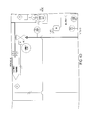
- FIG. 1 illustrates an example of a block diagram of a hydrocarbon vapor (i.e., natural gas) recovery system that includes an oxygen reduction system, connected with an oil condensate storage tank, a flare or incinerator, and a sales pipeline, to provide recovered vapor to the sales pipeline, in accordance with an embodiment of the present invention.
- a hydrocarbon vapor (i.e., natural gas) recovery system that includes an oxygen reduction system, connected with an oil condensate storage tank, a flare or incinerator, and a sales pipeline, to provide recovered vapor to the sales pipeline, in accordance with an embodiment of the present invention.
- FIG. 2 illustrates an example of a block diagram of a vapor recovery system having a recirculation pressure/flow regulation system control valve and configured for internal recirculation of the recovered gas, in accordance with one embodiment of the present invention.
- FIG. 3 illustrates an example of a controller for a hydrocarbon vapor recovery system, in accordance with one embodiment of the present invention.
- FIGS. 4A-4I illustrate respective portions of an example of a hydrocarbon vapor recovery system, in accordance with one embodiment of the present invention.
- FIG. 5 illustrates an isometric view of an example of one embodiment of the present invention.
- FIG. 6 illustrates an example of an alternative embodiment of the present invention, including system 20 A.
- FIG. 7 illustrates another example of an alternative embodiment of the present invention, including system 20 B.
- FIG. 8 illustrates another example of an alternative embodiment of the present invention, including system 20 C.
- FIG. 9 illustrates another example of an alternative embodiment of the present invention, including system 20 D.
- FIG. 10 illustrates another example of an alternative embodiment of the present invention, including system 20 E.
- FIG. 11 illustrates another example of an alternative embodiment of the present invention, including system 20 F.
- FIG. 12 illustrates another example of an alternative embodiment of the present invention, including system 20 G.
- a hydrocarbon vapor (i.e., natural gas) recovery system 20 As shown in FIGS. 1-12 and as described herein, various embodiments of a hydrocarbon vapor (i.e., natural gas) recovery system 20 are disclosed. As described herein, embodiments of the invention provide for safe, efficient, and reliable recovery of substantial amounts of hydrocarbons and natural gas present in vent gas emissions, while preventing, through the use of an oxygen reduction system or sub-system 22 that reduces amounts of diatomic oxygen (also known as O 2 or dioxygen) from the recovered gas, thereby preventing concentrated oxygen from entering the sales gas pipeline 24 .
- diatomic oxygen also known as O 2 or dioxygen
- oxygen includes diatomic oxygen, dioxygen and O 2 .
- FIG. 1 an example is shown of a hydrocarbon recovery system 20 , having an oxygen reduction system 22 , connected with one or more condensate storage tanks 26 (with a thief hatch 27 and relief valve 29 ), a flare 28 , and a sales gas pipeline 24 to provide recovered vapor 30 to the sales gas pipeline 24 .
- fluids i.e., oil, gas, and/or water
- fluids i.e., oil, gas, and/or water
- a separator 36 such as a three-phase separator
- Natural gas wells 34 produce natural gas and liquids, including liquid-phase hydrocarbons and water.
- Liquids are removed from the produced stream 32 by a separator 36 immediately downstream of the production wellhead 34 .
- the separator 36 separates liquid H 2 O (shown as 37 ) and sends it to water vault(s) 40 , while liquid hydrocarbons (also known as oil condensate 42 ) are sent to large oil condensate storage tank(s) 26 that typically maintain pressures from atmospheric pressure to 1 psig.
- the separator 36 also sends the natural gas 38 to the sales pipeline 24 for further conventional processing downstream.
- the separator 36 typically operates at sales pipeline pressure which can typically range from 20 psig to over 500 psig, significantly higher than atmospheric pressure.
- the storage tank 26 is typically at a much lower pressure, typically between 0 to 1 psig, with 1 psig being a maximum allowable working pressure for many oil condensate storage tanks 26 . Accordingly, as oil 42 moves from the separator 36 to the storage tank 26 , vent gases/vapor emissions 44 are created (the terms vent gas, vent gas emissions, vent gas vapor emissions, flash gas, emission vapors, flash emissions, vapor, emissions, and combinations thereof are used interchangeably herein).
- the inlet of the recovery system 20 (including oxygen reduction system 22 in this example) is plumbed in parallel with inlet(s) of the flare(s) 28 , with both the vapor recovery system 20 and flare(s) 28 downstream of the storage tanks 26 so that the recovery system 20 can capture the vent gas emissions 44 and convert such vent gas emissions 44 to recovered vapor 30 to be sent to the sales pipeline 24 .
- the flare 28 can also incinerate vent gas emissions 44 under certain circumstances, described below, for instance when the volume of vent gas emissions 44 surpasses the capacity of the recovery system 20 , or when vent gas emissions 44 are contaminated with excessive oxygen/air.
- a flow meter 46 can be provided in-line with the output of the recovery system 20 to measure the amount of recovered vapor 30 .
- a manifold 50 is provided connecting the one or more tanks 26 to the suction of recovery system 20 , and, in one embodiment one or more oxygen sensors 52 detect the oxygen content of the gas/vapor 44 at the inlet to the recovery system 20 .
- a pressure sensor 53 measures the pressure of the vent gas 44 at the inlet to the system 20 , which effectively is a measurement of the pressure in the tanks 26 .
- the inlet oxygen sensor 52 includes a diaphragm pump, which provides enough motive pressure to move the gas stream through an oxygen sensor/analyzer; and after it has been analyzed, the sampled gas stream is sent back just upstream of the inlet motor valve 56 and the inlet check valve 54 , in one example (see also FIG. 4 along Line P 1 ).
- This front-end oxygen level detection provides a safety mechanism in that vent gas emissions 44 which are excessively rich or high in oxygen content are burned off at the flare 28 and not recovered by the system 20 .
- the recovery system 20 through the use of the inlet oxygen sensor 52 —detects whether the vent gas emissions/vapors 44 are contaminated with excessive amounts of oxygen/air (i.e., more than 3% concentration by volume or more depending upon the implementation). If so, the inlet valve 56 of the recovery system 20 closes, which has the effect of sending the recovery system 20 into full recirculation mode and these highly-contaminated vent gas emissions 44 are subsequently incinerated by the flare 28 .
- the controller 60 determines that the flash emissions 44 are not contaminated with excessive oxygen/air (i.e., less than 3% concentration in one embodiment)
- the inlet valve 56 opens, allowing the flash emissions 44 to be recovered by the recovery system 20 .
- the gas 44 is either directed to the burner 28 for incineration or to enter recovery system 20 through the series of inlet valve 56 (which can be a motor valve), check valve 54 (which can be a swing-type check valve), and a flame arrester 58 .
- the opening or closing of inlet motor valve 56 is under the control of controller 60 (such as Programmable Logic Controller (PLC) 60 shown in FIGS. 2-3 ).
- controller 60 such as Programmable Logic Controller (PLC) 60 shown in FIGS. 2-3 ).
- PLC Programmable Logic Controller
- inlet motor valve 56 When inlet motor valve 56 is open, gas 44 enters a compression system 62 (described below as including, in one example, a series of scrubbers and compressors) where the gas 44 is compressed and then heated through heating system 64 , in one example of this disclosure.
- the gas 44 After the gas 44 is heated by heating system 64 , the gas 44 passes through another flame arrester 66 that quenches any flames that could propagate back or upstream, and then enters an oxygen removal subsystem 22 , described in greater detail below, which includes, in one example, one or more reactors or vessels which remove or reduce oxygen (e.g., dioxygen O 2 ) from the gas stream.
- An outlet oxygen sensor 68 monitors and detects the oxygen concentration level present in the gas exiting the oxygen reduction system 22 .
- the gas output 30 from the oxygen reduction system is either, under the control of controller 60 , passed to the sales pipeline 24 by closing recirculation valve 70 , or internally recirculated by opening recirculation valve 70 (which is also under the control of controller 60 ).
- inlet motor valve 56 is 100% closed in one example. However, if a lesser volumetric flow rate of gas enters the recovery system's inlet motor valve 56 , when compared to the compressor's capacity at a given operating speed, the recirculation valve 70 partially opens to provide “make-up” volume in order to maintain a set pressure in the 1 st -Stage inlet suction scrubber vessel. The proper amount of recirculation valve 70 lift is determined by the controller 60 closed control loop (which can be a PID or PI loop).
- four conditions can cause controller 60 to close the inlet motor valve 56 and subsequently place the recovery system 20 in a full recirculation mode that recirculates gas 44 internally within recovery system in such a way that all gas volume that passes through the compressor is supplied by the recirculation line alone such that no gas volume enters through the inlet valve 56 of recovery system 20 : i) if there is low pressure upstream of the inlet check valve 54 (as measured by pressure sensor 53 ) being drawn off of the oil tanks 26 (such as, by way of example, a positive pressure of 0.25 oz/in 2 or less, which indicates that there is little or no vent gas 44 in the tanks 26 ), ii) if there is too much oxygen detected by O2 sensor 52 in the gas 44 present at the inlet of system 20 (such as, by way of example, an oxygen concentration of greater than 3 percent in one example), iii) if there is too much oxygen detected by sensor 68 at the outlet of the system 20 (such as, by way of example, an oxygen concentration of
- the recirculation valve 70 is fully closed and the gas 30 at the outlet of system 20 (exiting from oxygen reduction system 22 ) is not recirculated through system 20 and is instead passed through flow meter 46 and outlet check valve 72 to the sales pipeline 24 .
- a back pressure regulator 78 (also shown as PCV-P 4 in FIG. 4 ) allows the system to depressurize by evacuating all gas contained within piping, reactor vessels, heat exchangers, coolers, scrubbers, and the compressor back to the oil storage tanks.
- the recirculation valve 70 opens to allow pressurized gas to travel through the recirculation valve.
- the piping downstream of the recirculation valve sends gas to both the inlet scrubber as well as the inlet of the back pressure regulator 78 .
- the back pressure regulator 78 is set, in one embodiment, to 5 psig.
- the pressure downstream of the valve rises in an attempt to reach equilibrium across the valve.
- the back pressure regulator 78 opens and allows this pressurized gas to evacuate back to the oil storage tanks. The flares on location will incinerate this gas as the oil storage tank pressure rises.
- the control of the recirculation valve 70 to allow depressurization during the event of a shutdown can be accomplished in a number of ways.
- One way is open up the valve to a static position (i.e., 50%, 100%, or any other amount above 0%) and allow the gas to move through the open valve in an attempt to equalize pressure across the valve.
- Another method of control is to continue to use the controller 60 (i.e., closed-loop PI or PID controller of FIG. 3 ) and shift the desired pressure setpoint of the first stage inlet scrubber that is higher than the setpoint of the back pressure regulator 78 .
- the position of the valve will vary to keep the pressure in the first stage inlet scrubber no higher than the setpoint programmed into the controller.
- the back pressure regulator 78 will allow gas to move through it as long as the gas pressure is higher than the back pressure regulator's setpoint, effectively depressurizing the system.
- FIG. 2 shows a block diagram of a controller 60 receiving a signal from a pressure sensor 53 at the inlet of the recovery system 20 (controller 60 also receives other input signals such as a signal from the oxygen sensor 52 at the inlet to the system 20 and a signal from the oxygen sensor 68 at the outlet of system 20 ); and controller 60 has an output signal that is coupled to the Current-to-Pressure converter 80 ( FIG. 2 ) that controls the recirculation motor valve 70 .
- controller 60 can detect whether various conditions for recirculation are present or not, and controller 60 controls the position of recirculation motor valve 70 to permit recirculation to occur (and if so, controller 60 can also finely adjust the amount or level of recirculation to achieve a desired pressure level at the input of system 20 as detected by pressure sensor 76 ) or to permit gas to be directed out of recovery system 20 to sales pipeline 24 .
- gas is recirculated through recovery system 20 if there is low pressure in the oil tanks 26 (such as, by way of example, a positive pressure of 0.25 oz/in 2 ) which indicates that there is little or no vent gas 44 in the tanks 26 .
- the recirculation of gas within the system 20 will have the effect of maintaining system 20 operating continuously with both reactors of the oxygen removal system 22 maintaining high enough temperatures to remove oxygen, ready for when greater amounts of oxygen-contaminated vent gas 44 become present in the tank 26 .
- Recovery system 20 in accordance with various embodiment of the present invention, can be used in various environments or situations where the production of vent gases 44 from tanks 26 is regularly occurring, such as where vent gases are typically present during operation of wells 34 .
- Recovery system 20 can be particularly useful to recover vent gas emissions 44 for new or newer wells 34 with high production rates of liquid hydrocarbons that typically produce substantial amounts of vent gas emissions 44 .
- recovery system 20 operates without a bladder or flexible storage tank collecting vent gas 44 at the front end of the system, and instead system 20 can operate continuously, always capable of processing vent gas 44 . Since no bladder is used in system 20 , the size and footprint of system 20 can be reduced when compared to some systems that use a bladder to gather and collect gas.
- FIG. 3 illustrates a controller 60 (such as a Programmable Logic controller (PLC)) with various inputs and various output signals in accordance with one embodiment of the present invention
- FIG. 4 illustrates an example of a specific implementation of a recovery system 20 , in accordance with one embodiment of the present invention.
- FIGS. 3-4 will be referenced in the following description of an example of an embodiment of the invention.
- PLC Programmable Logic controller
- gas 44 enters recovery system 20 along process line P 1 , shown in FIG. 4 , through a check valve 54 and a normally-opened ball valve in series with inlet motor valve 56 .
- the ball valve is a manual operated valve, and should only be closed if the system is being shut down or relocated. During normal operation, the ball valve will remain open.
- Inlet motor valve 56 can operate as a flow control valve and remain opens unless any of the four conditions, described above, occur either alone or in combination, such that the recovery system 20 is in a recirculation mode; and if those conditions occur, then the inlet motor valve 56 will be closed and recirculation valve 70 will be opened.
- the vent gas 44 goes into a first stage inlet scrubber with a blow case.
- the blow case pushes any liquids that collect at the bottom of the scrubber out of the vessel.
- the liquids are sent out to the same tanks 26 where the vapors 44 came from through a separate line.
- the scrubber scrubs out the liquids through means of reducing the stream's velocity in a vessel with a larger diameter than inlet and outlet piping. Since liquids are no longer entrained in fast a moving gas stream and are denser than the gas, gravity causes the liquids fall to the bottom in the scrubber while the gas moves to outlet nozzle located near the top of the scrubber vessel.
- Gas 44 exits the first stage scrubber (shown as Line P 3 in FIG. 4 ) and enters a flame arrestor just before the first stage of compression.
- the flame arrestor is used as a safety measure, in the unlikely event of a flammable gas mixture with a source of ignition the first stage cylinder, to prevent flames from traveling upstream.
- the first stage of compression compresses the gas 44 from atmospheric pressure to approximately 35 to 39 psig, depending on discharge pressure.
- a vibration sensor is provided on the compressor to detect any mechanical problems with the compressor that could cause it to become unbalanced and vibrate during operation.
- a temperature sensor is provided at the discharge of the first stage compressor to ensure that the temperature of the gas stream is not excessive (i.e., not exceeding 20% above the expected discharge temperature, in one example 192 degrees Fahrenheit).
- the compressed gas exits the first stage of compression, as shown as Line P 4 in FIG. 4 , where the gas enters a second stage scrubber which also separates and removes fluids from the gas stream.
- the liquids fall out of the gas stream in the second scrubber to the bottom of the scrubber vessel, while the gas flows to the top of the second scrubber and moves (shown as Line P 5 ) into a second stage of compression.
- the second stage compressor increases the pressure of the gas stream to approximately about 146 psig, assuming 390 psig of discharge.
- a temperature sensor is provided at the discharge of the second stage compressor to ensure that the temperature of the gas stream is not excessive (i.e., not exceeding 307 degrees Fahrenheit).
- the compressed gas stream exits the second stage compressor as shown at Line P 6 , where the gas stream then enters a section of the air-cooled heat exchanger which has 4 separate sections.
- section one of the air-cooled heat exchanger (also referred to as “cooler”) 72 is used as a radiator for the engine
- Line P 6 enters section 2 of the cooler 72 , in one example, where the gas cools off to a certain point (i.e., 210 degrees Fahrenheit) prior to entry into the third stage of compression.
- the gas steam having exited section 2 of the cooler 72 , then enters a third scrubber, which also separates and removes fluids from the gas stream.
- the gas stream exits the third scrubber as shown at Line P 8 , where it enters a third stage of compression.
- the third stage of compression is configured to compress the gas stream to a final discharge pressure, which will typically be approximately the same pressure as the gas sales line (such as, in one example, 390 psig).
- a natural gas powered fired engine is used to drive the three stages of compression (which may be in for form of a multi-stage reciprocating compressor) that will pressurize the gas stream from at or just above atmospheric pressure to whatever the pressure of the gas gathering line is operating at.
- the output of the third stage of compression is shown as Line P 9 , which is thermally insulated and coupled into a pressure safety valve. If the discharge pressure is too high (i.e., in excess of 400 psi), then the excess pressure is relieved through the pressure safety valve. The pressure and temperature of the gas stream coming out of the third compressor are measured before the gas enters an exhaust gas heat exchanger.
- the exhaust gas heat exchanger takes hot exhaust gas from the engine and transfers heat into the gas stream to increase the temperature of the gas stream prior to the gas stream's entry into the oxygen reduction reactors. Increasing the temperature of the gas streamhelps initiate the catalytic oxygen removal reaction which removes oxygen from the gas stream.
- the output of the heat exchanger is also thermally insulated, shown as Line P 10 , and enters the input of a first reactor, which is also thermally insulated and filled with sulfur scavenging materials that remove any sulfur that could be present in the gas stream which thereby protects a downstream oxygen removal catalyst that can be poisoned by any sulfur present in the gas stream.
- the output of the first reactor is shown as Line P 11 , which is also thermally insulated and coupled with a second flame arrester prior to entry into a second reactor inside of which oxygen is removed through catalytic combustion with hydrocarbons present in the gas stream. Since the second reactor is removing the oxygen through combustion, the flame arrester prevents any flames from traveling back into Line P 11 in the unlikely event that any flames are present in the second reactor.
- any oxygen present is reacted with the hydrocarbons in the gas stream and is subsequently removed and converted into both carbon dioxide and water in the process stream.
- all catalytic materials i.e., zinc oxide and oxygen reducing/removing catalysts
- the output of the second reactor is shown as Line P 12 , where the gas stream is very hot at this point and is directed into Section 3 of the cooler to cool down the gas stream.
- the output of Section 3 of the cooler is shown as Line P 13 which is either directed to the sales line 24 , or for recirculation as previously described.
- the recovered vapor 30 is directed to the sales pipeline, no further cooling by the recovery system's cooler 72 is necessary because an elevated temperature (i.e., 250 degrees Fahrenheit) at and immediately downstream of Line P 13 is desired in order to ensure that elements in the stream do not cool to the point of condensing to the liquid phase as a result of thermal losses to the pipe, ground, air, etc before passing through the custody transfer meter.
- an elevated temperature i.e., 250 degrees Fahrenheit
- the resultant temperature can be tuned to be below whatever contractual temperature limitations are in place (i.e., 120 degrees Fahrenheit) by throttling the airflow across section 3 of the cooler 72 .
- the recovered vapor 30 is directed to be recirculated through the recirculation valve 70 , it can be further cooled to a lower temperature (i.e., 100 degrees F.) through section 4 of the cooler 72 . Further pressure drop across recirculation valve 72 will ensure a further temperature drop of the gas stream by means of the Joules-Thompson effect. This will ensure that the gas stream in the recirculation line is at a low enough temperature (i.e., 100 degrees Fahrenheit or below) as it re-enters the 1 st -Stage suction scrubber to ensure that there is no overheating of the mechanical equipment, including the compressor.
- a low enough temperature i.e., 100 degrees Fahrenheit or below
- this final section of cooling can be bypassed or omitted depending on characteristics specific to the site's production characteristics, ambient surroundings, gas composition, and discharge pressures, as long as the gas temperature in the recirculation line is cool enough not to damage either the recirculation valve or compressor and associated components.
- the first and second reactors or pair of vessels may be implemented using generally elongated, cylindrical pressure vessels each having an input and an output end.
- An alternative embodiment could combine all catalytic materials (i.e., sulfur scavenging catalysts such as zinc oxide and oxygen removing/reducing catalysts such as palladium) within the same vessel/reactor, however, separate reactors/vessels for both sulfur will be discussed within for explanation purposes.
- the first pressure vessel 22 A may include zinc oxide material (i.e., a bed of zinc oxide) or other material which acts as a sulfur scavenger; and the second pressure vessel may include a palladium catalyst or other material which operates to reduce the dioxygen (O 2 ) concentration by lowering the activation energy required to facilitate combustion between oxygen and the heated gas stream being processed by the recovery system 20 , effectively eliminating the limiting reagent as the heated gas stream passes through the second pressure vessel that contains the palladium catalyst at or above a given temperature and pressure.
- oxygen is the limiting reagent and the threshold pressure and temperature vary with the composition of the gas stream.
- the second pressure vessel reactor is positioned vertically or substantially vertically, so that the natural gas stream flows downwardly through the reactor vessel which essentially packs in the catalytic pebbles and thus reduces the possibility of any channeling of the gas stream. This also ensures contact between the processed natural gas stream and the materials contained in the reactor, respectively resulting in the most efficient reduction of oxygen content.
- a bed of zinc oxide is provided in the first reactor 22 A which acts as a sulfur scavenger and protects the palladium catalysts that are in the second reactor from the poisoning effects of sulfur.
- the zinc oxide bed in the first reactor may be replaced periodically.
- palladium catalyst in the second reactor 22 B, other materials (i.e., noble metals) may be used, including platinum or palladium/platinum blends.
- materials comprising metals such as nickel, cobalt, copper, iron, silver, and gold can be used to cause the oxygen present in the gas stream to react with the metals and reduce the oxygen content in the gas stream.
- the second reactor 22 B uses a palladium catalyst to facilitate the combustion of the oxygen with hydrocarbons in the processed stream of natural gas while in the second reactor.
- the oxygen in this case is the limiting reagent and is thus burned up once the light-off temperature is achieved within the second reactor when the gas is at sufficient temperature and pressure, effectively removing or reducing oxygen concentrations present in the gas stream.
- thermocouples or RTD's thermocouples or RTD's
- RTD's thermocouples or RTD's
- the system 20 may be shut down until the second reactor 22 B temperature cools down to an acceptable temperature, at which time the system 20 can be re-started (i.e., 600 Fahrenheit).
- the natural gas stream Having passed through the first and second reactors 22 A-B at the required pressure and temperature, the natural gas stream has substantially less sulfur and oxygen O 2 content than it had it prior to entry into the oxygen reduction system.
- a trace oxygen analyzer can be used as an oxygen sensor 68 that is coupled with the output of the second reactor of the oxygen reduction system, about Line P 13 as shown in FIG. 4 .
- a pressure reducing regulator valve can be used to reduce the pressure of the gas (i.e., from 400 psig to 100 psig by a Fisher 95H-1724 pressure regulator in one example).
- a second pressure reducing regulator valve can be used in series to further reduce pressure (i.e., from 100 psig to 20 psig by a Fisher 67CF-1664 pressure regulator in one example), and equipped with a filter and an automatic drain for any liquids that might collect. After passing through both pressure reducing regulator valves the pressure is reduced to acceptable levels, liquids are drained, and contaminants are filtered out of the gas stream so that it can be accepted by the analyzer.
- the gas stream 30 If the gas stream 30 is directed to the sales lines 24 , it will enter Line 13 and continue traveling through the check valve out of the recovery system into a normally open ball valve to be metered where it will then enter into the sales line and be sold, such as to a midstream gas gathering company in one example.
- the system directs the gas stream such that gas will not enter the sales line 24 and will instead be recirculated internally in the system 20 so it will not leave the system boundary.
- the gas stream at Line P 13 is directed into Section 4 of the cooler to further cool down the gas stream in order to protect equipment from excessive temperatures (i.e. recirculation valves, compressor valves, etc.) and also to make sure that the gas that reenters at the first stage suction scrubber vessel of the recovery system 20 through that recirculation loop is cool enough (i.e., equal to or less than 100 degrees Fahrenheit, in one example).
- the cooled gas stream for recirculation exits Section 4 of the cooler and is shown as Line P 14 where pressure is detected that corresponds to the pressure in the reactors.
- the recirculated gas is directed into the first stage scrubber through a recirculation valve 70 .
- the recirculation valve is implemented using two electro-mechanical valves connected in parallel ( FIG. 4 ) that the gas stream travels through for recirculation before the gas stream gets to the first stage inlet scrubber.
- One of the valves is used to unload the compressor and let it pump gas with very little restriction and pressure rise. It is a “full port,” unrestricted valve meaning that its port size is no smaller than the valve body's inlet or outlet.
- This valve In operation, it is either fully open or fully closed and is under the control of the controller 60 .
- This valve can be used primarily during engine restart of the system, and in one example this valve remains closed during normal recirculation operations and also remains closed when the gas stream is being directed to the sales pipeline 24 .
- the second valve in parallel with the first valve, is used to regulate flow and the resultant pressure downstream in the first stage scrubber vessel while the compressor is operating.
- This precise regulation is made possible with variable valve lift, controlled by the controller's 60 closed control loop with pressure in the first stage scrubber vessel being the process variable (PV) with a given set point (i.e., 0.25 psig vacuum) and the electrical signal to the Current-Pressure converter 80 as the scaled control variable.
- PV process variable
- a signal from the pressure sensor transmitter located on the first stage scrubber 76 is received by the controller 60 as an electrical analog signal with varying magnitudes, in one example 4 to 20 milliamps (mA).
- the controller takes that pressure signal and determines through, in one example, a three-parameter (i.e., proportional, integral, and derivative) closed control loop, the correct output signal to transmit to the second valve to maintain the a desired set point pressure at that first stage inlet scrubber.
- the set point pressure is determined by an operator or administrator of the recovery system. In one example that accounts for the pressure drop across the inlet check valve 54 , the set pressure during recirculation can be slightly at a vacuum, such as ⁇ 0.25 psi.
- the controller's output signal is coupled with a Current-Pressure converter 80 ( FIG. 2 ) also known as an IP converter that takes an electrical signal in the form of current (i.e., 4-20 mA) and transfers that into a pressure signal that varies linearly with the electrical signal.
- the pressure output of converter 80 is coupled with the control line of the second valve to control the valve's lift off of its valve seat on the same valve, which effectively control the flow rate of gas through that valve (shown as FCV-P 2 in FIG. 4 ).
- FIG. 4 an example is illustrated of the engine-specific portion of an electrical power system that may be employed in a recovery system 20 , in accordance with one embodiment of the present invention.
- two or more batteries may be connected in series, including a 12 volt battery and another 12 volt battery, and therefore the series combination provides a 24 volt potential.
- Energy from a generator 60 (which may be implemented using an alternator) can be coupled with the batteries to provide re-charging during operations of the engine.
- FIG. 4 also illustrates both power to the ignition as well as power to the engine starter is controlled through respective electrical relays. An output that controls Engine Speed, as well as the Engine Speed sensor (shown as ST-E1), are shown.
- FIG. 3 illustrates one example of a controller 60 that can be used in a recovery system 20 , in accordance with one embodiment of the present invention.
- the controller 60 is a programmable logic controller (PLC), such as a Direct Logic 06 PLC, although any capable controller, processor or logic can be used.
- PLC programmable logic controller
- the controller 60 may be configured to receive a plurality of inputs, either directly or through interface circuitry, and the inputs may include but are not limited to: engine speed input, which may be derived from a magnetic pickup sensor on the engine flywheel to monitor engine speed; engine oil pressure; engine coolant temperature; engine oil level; engine oil temperature; engine coolant level; position(s) of emergency shutdown button(s); stage 1 inlet scrubber high liquid level, which indicates that the level of scrubbed liquids inside the respective scrubber vessel is outside (i.e., too high) of acceptable operating conditions; stage 2 inlet scrubber high liquid level, which indicates that the level of scrubbed liquids inside the respective scrubber vessel is outside (i.e., too high) of acceptable operating conditions; stage 3 inlet scrubber high liquid level, which indicates that the level of scrubbed liquids inside the respective scrubber vessel is outside (i.e., too high) of acceptable operating conditions; stage 1 inlet scrubber pressure, which can indicate a potential issue with the recirculation valve 70 or flow rate through the recirculation
- the controller 60 may also be configured to provide one or more outputs, either directly or through conventional interface circuitry, such as but not limited to: a control signal for controlling inlet valve 56 , described above; a control signal for a compressor unloader valve, which may have a delay 2 minutes or longer, so that the engine idles for that delay period until the engine coolant reaches acceptable operating temperatures (i.e., above 140 degrees Fahrenheit) before increasing rotational speed as the compressor is loaded; engine fuel solenoid control signal for opening a valve to provide fuel to the engine; inlet oxygen sensor pump, which activates inlet oxygen sensor pump 52 ; electronics cabinet heater control, which can be used to maintain a desired temperature range (i.e., between 60 and 80 degrees Fahrenheit), protecting any temperature-sensitive devices inside the electronics cabinet(s); recirculation valve control of valve(s) 70 , described above; engine ignition control signal; engine start control signal for energizing a starter relay for the engine starter; engine speed control, which can be used to govern engine rotation speed to a desired setpoint
- the controller 60 may also be provided with a display and a keyboard, or with a touch screen, in order to provide status information regarding the system, and/or to provide controls for an operator.
- the controller 60 may implement one or more functions or operations as described herein. In one example, the controller 60 implements one or more of the following operations or sequence of operations:
- controller 60 for a recovery system 20 could be implemented using one or more of these operations, or combinations thereof, in accordance with other embodiments of the present invention.
- FIG. 5 provides an isometric view of one embodiment of the present invention, showing various components as described herein. It is understood that other embodiments could be formed wherein the components are positioned in different locations than as shown in FIG. 5 .
- FIGS. 6-12 illustrate various alternative embodiments of system 20 .
- the system 20 A is downstream of a separate compressor system.
- system 20 A has a heating system to get the process gas stream up to a temperature which would allow the reaction in the catalyst to take place.
- the gas would then flow through the reactor, where the diametric oxygen is removed from the gas.
- the recovered gas passes through a system flow meter into the gas pipeline. If the recovered gas doesn't meet the specifications needed to go into the gas pipeline, the recovered gas can go through a recirculation valve and enter system 20 A once again upstream of the compression system.
- the system 20 B is downstream of a compressor system that also includes a heat source, either through compression or with a heater added to it.
- the recovered gas would then flow through the reactor, where the diametric oxygen is removed from the system. Then the recovered gas would go through a system flow meter and into the gas pipeline. If the recovered gas doesn't meet the specifications needed to go into the gas pipeline, the recovered gas would go through a recirculation valve and enter system 20 B once again into an input to the compression system.
- system 20 C is downstream of a compressor system that includes a heat source, either through compression or with a heater added to it, similar to FIG. 7 .
- the recovered gas if the recovered gas doesn't meet the specifications needed to go into the gas pipeline, the recovered gas would go through a recirculation valve and flow directly to a VOC burner/flare 28 .
- system 20 D is downstream of a gas source.
- system 20 D has a heating system to get the recovered gas stream up to a temperature which would allow the reaction in the catalyst to take place.
- the recovered gas would then flow through the reactor, where the diametric oxygen is removed from the recovered gas. If the recovered gas meets the specifications needed to go into the gas pipeline, the recovered gas is then compressed, and follows the path to the pipeline. If the recovered gas does not meet the specifications needed to go into the pipeline, the gas then goes to a VOC burner/flare.
- system 20 E is downstream of a gas source.
- a heating system heats the recovered gas stream up to a temperature which would allow the reaction in the catalyst to take place.
- the recovered gas would then flow through the reactor, where the diametric oxygen is removed from the recovered gas.
- the recovered gas then goes into the compressor system. If the recovered gas meets the specifications needed to go into the gas pipeline, the gas then follows the path to the pipeline. If the recovered gas does not meet the specifications needed to go into the pipeline, then in contrast with FIG. 9 , in the example of FIG. 10 the recovered gas then goes through a recirculation valve which brings it to the front end of system 20 E.
- system 20 F receives vapors from a gas source that has been compressed by a compressor.
- the gas would then flow through the reactor, where the diametric oxygen is removed from the recovered gas.
- the reactor is heated, which allows the reaction between the gas and the catalyst to take place. If the recovered gas meets the specifications needed to go into the gas pipeline, the gas is then compressed, and follows the path to the pipeline. If the gas does not meet the specifications needed to go into the pipeline, the gas then goes through a recirculation valve which brings it to the front end of the compressor.
- system 20 G is similar to system 20 F of FIG. 11 , except that if the recovered gas from system 20 G does not meet the specifications needed to go into the pipeline, the recovered gas then goes directly to a VOC burner/flare.
- the output of embodiments of the invention can be used to provide natural gas and natural gas liquids, and can be used as an energy source, as a purified fuel source for on-site or off-site equipment, as fuel for refrigeration processes or other processes, as fuel in other uses where corrosion due to oxidation is a concern, or as fuel for other systems or environments where natural gas or natural gas liquids are used.
Abstract
Description
ZnO+H2S→ZnS+H2O
Acting as a sacrificial bed, the zinc oxide bed in the first reactor may be replaced periodically.
- POWER ON to PLC, Touchscreen, End Devices, etc.
- Upload:
- PLC Program version to display on touchscreen
- Setup and Scale Analog Input Channels:
- Storage Tank Pressure Transmitter: 0-57.8 oz/in2
-
Stage 1 Scrubber Pressure Transmitter: 0-44.7 psia -
Stage 2 Scrubber Pressure Transmitter: 0-100 psig -
Stage 3 Scrubber Pressure Transmitter: 0-200 psig - Reactor Discharge Pressure Transmitter: 0-500 psig
- Compressor Lube Oil Pressure Transmitter: 0-100 psig
- Engine Lube Oil Pressure Transmitter: 0-100 psig
- Oxygen Reactor Inlet Temperature Transmitter: 0-1000 deg F.
- Oxygen Reactor Outlet Temperature Transmitter: 0-1000 deg F.
- Engine Coolant Temperature Transmitter: 0-300 deg F.
- Engine Exhaust Gas Pre-Catalytic Converter Temperature Transmitter: 0-2000 deg F.
- Engine Exhaust Gas Post-Catalytic Converter Temperature Transmitter: 0-2000 deg F.
- Oxygen Analyzer 1: Concentration at Inlet Valve: 0-25%
- Oxygen Analyzer 2: Concentration at Reactor Discharge Valve: 0-25%
-
Stage 1 Compression Discharge Temperature Transmitter: 0-300 deg F. -
Stage 2 Compression Discharge Temperature Transmitter: 0-1000 deg F. -
Stage 3 Compression Discharge Temperature Transmitter: 0-1000 deg F. - Recirculation Gas Stream Temperature Transmitter: 0-300 deg F.
- Setup and Scale Analog Output Channel:
- Recirculation Control Valve Bonnet Pressure: 0-30 psig
- List of Discrete Inputs:
- Magnetic Proximity Sensor: Engine Flywheel Gear Tooth counter
-
Stage 1 Inlet Scrubber High Liquid Level Switch -
Stage 2 Inlet Scrubber High Liquid Level Switch -
Stage 3 Inlet Scrubber High Liquid Level Switch - Engine Coolant Low Liquid Level Switch
- Compressor Crankcase Lube Oil Low Liquid Level Switch
- Engine Crankcase Lube Oil Low Liquid Level Switch
- Vibration Detector: Compressor
- Vibration Detector: Engine
- Vibration Detector: Cooler
- Compressor Lube Oil High Temperature Switch: >190 deg F.
- Engine Lube Oil High Temperature Switch: >220 deg F.
- Compressor Discharge High Pressure Switch: >390 deg F.
- Electrical Cabinet Low Temperature Thermostatic Switch
- Compressor Lube Oil Distribution Block No-Flow Indicator Switch
- Emergency Shut Down Pushbutton (referred to as ESD PB throughout)
- List of Discrete Outputs:
- Inlet Motor Valve: OPEN/CLOSE
- Compressor Motor Valve: OPEN/CLOSE
- Engine Fuel Valve: OPEN/CLOSE
- Engine Starter Power: Relay ON/OFF
- Engine Ignition Power: Relay ON/OFF
- Diaphragm Pump Supply to Oxygen Analyzer 1: ON/OFF
- Compressor Crankshaft Pre-start Lube Pump Valve: OPEN/CLOSE
- Electrical Cabinet Enclosure Heaters: ON/OFF
- Engine Rotational Speed Control: 900/1800 RPM
- Set all Negative Analog Input Values to Zero
- Set up Fast Counter for Engine Flywheel Magnetic Pickup—determine Engine speed in RPM
- Counts Gear teeth passing by per second
- Divides by number of gear teeth on engine flywheel (SAE #3: 127 teeth)
- Multiply by (60 sec/min) to get Revolutions per Minute
- List of Shut Downs:
- Engine Lube Oil Low Pressure: <15 psig
- Engine Coolant High Temperature: >212 deg Fahrenheit
-
Stage 1 Scrubber High Pressure: >17.2 psia (at 5000 ft elevation) -
Stage 1 Scrubber Low Pressure: >7.7 psia -
Stage 2 Scrubber High Pressure: >46.7 psia -
Stage 2 Scrubber Low Pressure: >26.4 psia -
Stage 3 Scrubber High Pressure: >171.6 psia -
Stage 3 Scrubber Low Pressure: >91.1 psia - Reactor Discharge High Pressure: >400 psig
- Compressor Lube Oil Low Pressure: >25 psig
- Engine Lube Oil Low Pressure: >25 psig
- Oxygen Reactor Inlet High Temperature: >600 deg F.
- Oxygen Reactor Outlet HighTemperature: >700 deg F.
- Engine Coolant Temperature Transmitter: 0-300 deg F.
- Engine Exhaust Gas Pre-Catalytic Converter High Temperature: >1300 deg F.
- Engine Exhaust Gas Post-Catalytic Converter High Temperature: >1400 deg F.
- Engine Exhaust Gas High Temperature Differential: >200 deg F.
- Oxygen Analyzer 1: Concentration at Inlet Valve: >10%
- Oxygen Analyzer 2: Concentration at Reactor Discharge Valve: >10 ppm for 24 hours
-
Stage 1 Compression Discharge High Temperature: >192 deg F. -
Stage 2 Compression Discharge High Temperature: >307 deg F. -
Stage 3 Compression Discharge High Temperature: >330 deg F. - Recirculation Gas Stream High Temperature: >125 deg F.
-
Stage 1 Inlet Scrubber High Liquid Level -
Stage 2 Inlet Scrubber High Liquid Level -
Stage 3 Inlet Scrubber High Liquid Level - Engine Coolant Low Liquid Level
- Compressor Crankcase Lube Oil Low Liquid Level
- Engine Crankcase Lube Oil Low Liquid Level
- Vibration Detector: Compressor
- Vibration Detector: Engine
- Vibration Detector: Cooler
- Compressor Lube Oil High Temperature: >190 deg F.
- Engine Lube Oil High Temperature: >220 deg F.
- Compressor Discharge High Pressure: >390 deg F.
- Compressor Lube Oil Distribution Block No-Flow Indicator Switch
- Emergency Shut Down Pushbutton Pushed In
- Engine Failed to Start
- Engine Over Speed
-
- Engine is authorized to start and run if no Shutdowns are Present
- Engine Starter is turned for 8 seconds then rests for 20 seconds if the following conditions are ALL true:
- Engine is authorized to run
- Engine speed is below 350 RPM
- The starter crank sequence has not occurred 8 times without successful engine start
- This results in a Failed to Start Shutdown
- Engine Ignition Relay is tuned on if the following conditions are ALL true:
- Engine is authorized to run
- Engine speed is above 10 RPM
- Engine Fuel Valve OPENS:
- 2 seconds after Engine Ignition turns on
- Engine at idle speed (900 RPM) until two minutes after Engine starts and Engine coolant temperature is above 140 deg Fahrenheit
- Compressor Unloader Valve OPENS if either of the following are true:
- When Engine Stops
- Stays open until 10 seconds after Engine reaches Full Speed
- Diaphragm Pump Supply to
Oxygen Analyzer 1 Powered ON if:- Diaphragm Pump Supply to
Oxygen Analyzer 1 Not Deactivated on Touchscreen, AND - No Shut Downs are present, AND
- Engine is running
- Diaphragm Pump Supply to
- Compressor Crank Shaft PreLubrication Pump Valve OPEN if any of the following are true:
- Engine is starting
- Stays open until 10 minutes after engine has successfully started
- Inlet Motor Valve OPEN if:
- One or Other of the following is true:
- Oxygen Concentration @ Inlet Motor Valve is below 3%, OR
- Oxygen Concentration @ Inlet Motor Valve is below 10% for 5 seconds every minute to throttle oxygen-rich vapor through the system without creating excessive temperatures in the reactors
- AND all of the following are true
- Oxygen Concentration @ Inlet Motor Valve is below 10%
- The Engine is Authorized to Run (discussed below)
- Tank Pressure is above 0.25 oz/sqin
- Unloader Valve is CLOSED
- Oxygen Concentration @ Reactor Discharge is below 10 ppm
- Inlet Valve Opening is Not Deactivated by Operator @ Touchscreen
- Final stage discharge & reactor pressures not within 20 psi of high pressure shutdown setpoint
- ESD PB NOT PUSHED IN
- One or Other of the following is true:
- Recirculation Valve Opening Control: Closed Control Loop
- Setup so that PID Closed Control Loop Adjusts Recirculation Valve Position to maintain
Stage 1 Inlet Scrubber Vessel Pressure at desired setpoint:- Process Variable:
Stage 1 Scrubber Vessel Pressure - Setpoint: 12.2 psia
- Control Output: Reverse Acting Signal to Current-Pressure Converter that controls Recirculation Valve Lift
- Tune Control Loop using
- Proportional Gain
- Integral Gain/Reset
- Derivative Gain/Rate only to be used when necessary
- Process Variable:
- Setup so that PID Closed Control Loop Adjusts Recirculation Valve Position to maintain
Claims (20)
Priority Applications (1)
| Application Number | Priority Date | Filing Date | Title |
|---|---|---|---|
| US14/678,336 US9776155B1 (en) | 2012-02-02 | 2015-04-03 | Hydrocarbon vapor recovery system with oxygen reduction |
Applications Claiming Priority (5)
| Application Number | Priority Date | Filing Date | Title |
|---|---|---|---|
| US13/365,247 US8992838B1 (en) | 2011-02-02 | 2012-02-02 | Hydrocarbon vapor recovery system |
| US201361826543P | 2013-05-23 | 2013-05-23 | |
| US201361918583P | 2013-12-19 | 2013-12-19 | |
| US201414286983A | 2014-05-23 | 2014-05-23 | |
| US14/678,336 US9776155B1 (en) | 2012-02-02 | 2015-04-03 | Hydrocarbon vapor recovery system with oxygen reduction |
Related Parent Applications (1)
| Application Number | Title | Priority Date | Filing Date |
|---|---|---|---|
| US201414286983A Continuation | 2012-02-02 | 2014-05-23 |
Publications (1)
| Publication Number | Publication Date |
|---|---|
| US9776155B1 true US9776155B1 (en) | 2017-10-03 |
Family
ID=59928448
Family Applications (1)
| Application Number | Title | Priority Date | Filing Date |
|---|---|---|---|
| US14/678,336 Active US9776155B1 (en) | 2012-02-02 | 2015-04-03 | Hydrocarbon vapor recovery system with oxygen reduction |
Country Status (1)
| Country | Link |
|---|---|
| US (1) | US9776155B1 (en) |
Cited By (5)
| Publication number | Priority date | Publication date | Assignee | Title |
|---|---|---|---|---|
| US20180030931A1 (en) * | 2016-07-29 | 2018-02-01 | Precision Compression, LLC | Compression system |
| US20190186690A1 (en) * | 2017-12-19 | 2019-06-20 | U.S. Army Research Laboratory Attn: Rdrl-Loc-I | Detecting and predicting mechanical failure due to lubrication loss in machines and movable components |
| US11149534B2 (en) * | 2015-09-15 | 2021-10-19 | Equinor Energy As | Method and system for processing a fluid produced from a well |
| US11248746B2 (en) * | 2019-08-19 | 2022-02-15 | BHE Compression Services, LLC | Methane and emissions reduction system |
| WO2022109308A1 (en) | 2020-11-19 | 2022-05-27 | Flogistix, Lp | Certified vapor recovery |
Citations (55)
| Publication number | Priority date | Publication date | Assignee | Title |
|---|---|---|---|---|
| US1653387A (en) | 1924-08-06 | 1927-12-20 | United Iron Works Inc | Storage tank for volatile liquids |
| US2126367A (en) | 1936-06-05 | 1938-08-09 | Continental Oil Co | Tank for volatile liquids |
| US2947379A (en) | 1958-04-21 | 1960-08-02 | Nat Tank Co | Petroleum vapor recovery system |
| US3331194A (en) | 1965-12-08 | 1967-07-18 | Zink Co John | Flare stack structure and apparatus treating and controlling flow of gases to and from stack |
| US3707157A (en) | 1971-08-04 | 1972-12-26 | Damon F Tipton | Natural gas saver with separator and compressor |
| US4273189A (en) | 1978-06-12 | 1981-06-16 | Carpenter Neil L | Method and apparatus for recovering natural gas from geopressured salt water |
| US4422301A (en) | 1980-05-07 | 1983-12-27 | Robert H. Watt | Evaporative loss reduction |
| US4579565A (en) | 1983-09-29 | 1986-04-01 | Heath Rodney T | Methods and apparatus for separating gases and liquids from natural gas wellhead effluent |
| US4747853A (en) | 1986-07-02 | 1988-05-31 | Imperial Chemical Industries Plc | Pressure control |
| US5132011A (en) | 1991-08-02 | 1992-07-21 | Petroleum Equipment Specialties, Inc. | Oil, water and gas mixture separator |
| US5135360A (en) | 1991-01-14 | 1992-08-04 | Anderson R David | Method and device for controlling tank vapors on a petroleum storage tank |
| US5139390A (en) | 1991-02-04 | 1992-08-18 | Rajewski Robert K | Pump and method for drawing vapor from a storage tank without forcibly drawing the vapor from the tank |
| US5149344A (en) | 1991-05-02 | 1992-09-22 | Texaco Inc. | Multi-phase flow and separator |
| US5195587A (en) | 1992-03-04 | 1993-03-23 | Conoco Inc. | Vapor recovery system |
| US5249593A (en) | 1992-06-29 | 1993-10-05 | Keystone International Holdings Corp. | Fluid pressure relief system for pressure vessels |
| JPH0834497A (en) | 1994-07-21 | 1996-02-06 | Tokico Ltd | Fuel-feeding device |
| US5524456A (en) | 1995-10-20 | 1996-06-11 | Public Service Marine Inc. | Pressure tank recycle system |
| US5651389A (en) | 1994-12-22 | 1997-07-29 | Anderson; R. David | Method and apparatus for controlling tank vapors |
| US5775442A (en) | 1996-10-25 | 1998-07-07 | Northland Production Testing, Ltd. | Recovery of gas from drilling fluid returns in underbalanced drilling |
| US5900137A (en) | 1996-06-27 | 1999-05-04 | Homan; Edwin Daryl | Apparatus and method for separating components in well fluids |
| US5970957A (en) | 1998-03-05 | 1999-10-26 | Ford Global Technologies, Inc. | Vapor recovery system |
| US5979481A (en) | 1998-02-17 | 1999-11-09 | Ayresman; Loren | Apparatus and method for vapor reduction for a fuel storage tank |
| US6209651B1 (en) | 1999-03-04 | 2001-04-03 | Roy F. Knight | Well production apparatus and method |
| US6363959B1 (en) | 1999-05-10 | 2002-04-02 | Parker-Hannifin Corporation | Fluid pressure regulator with differential pressure setting control |
| US6422313B1 (en) | 2000-06-15 | 2002-07-23 | Roy Knight | Apparatus and method for recovering waste production gases |
| US6527002B1 (en) | 1998-03-16 | 2003-03-04 | Istvan Szakaly | Apparatus and method for use with a container for storing a substance |
| US20030183394A1 (en) | 2002-03-12 | 2003-10-02 | Reitz Donald D. | Gas recovery apparatus, method and cycle having a three chamber evacuation phase for improved natural gas production and down-hole liquid management |
| US6681789B1 (en) | 2001-03-29 | 2004-01-27 | The United States Of America As Represented By The United States Environmental Protection Agency | Fuel tank ventilation system and method for substantially preventing fuel vapor emissions |
| US20050051503A1 (en) | 2003-09-06 | 2005-03-10 | Holland Robert W. | Coalescer media flexible container and method of use |
| US6881329B2 (en) | 2000-05-03 | 2005-04-19 | Schlumberger Technology Corporation | Gravity separator for multi-phase effluents |
| WO2005045173A2 (en) | 2003-08-13 | 2005-05-19 | Oil And Natural Gas Corp Ltd | A liquid seal for recovering flared gas |
| US6955704B1 (en) | 2003-10-28 | 2005-10-18 | Strahan Ronald L | Mobile gas separator system and method for treating dirty gas at the well site of a stimulated well |
| US7069942B2 (en) | 2001-07-03 | 2006-07-04 | Abb Gas Technology As | Method and apparatus for handling of covering gas |
| US20060144080A1 (en) | 2004-09-22 | 2006-07-06 | Heath Rodney T | Vapor process system |
| US20070284240A1 (en) | 2006-06-09 | 2007-12-13 | Roy Wade Rhodes | System and method for diagnosing and troubleshooting amine regeneration system |
| US7350581B2 (en) | 2005-05-11 | 2008-04-01 | Electronic Design For Industry, Inc. | Vapor recovery system |
| US20080202593A1 (en) | 2005-05-18 | 2008-08-28 | Blue Marble Engineering, L.L.C. | Fluid-flow system, device and method |
| US7504037B2 (en) | 2007-04-10 | 2009-03-17 | Paul Gibbs | Oil and vapor recovery system |
| US7645433B2 (en) | 2006-06-09 | 2010-01-12 | Newpoint Gas Services, Inc. | Optimization of reflux accumulator start-up in amine regeneration system |
| US7691344B2 (en) | 2004-01-15 | 2010-04-06 | Takeki Yoshimura | Oil reconversion device for waste plastics |
| US7695702B2 (en) | 2006-06-09 | 2010-04-13 | Newpoint Gas Services, Inc. | Optimization of amine regeneration system start-up using flash tank pressurization |
| US7735670B2 (en) * | 2006-10-17 | 2010-06-15 | Honeywell International Inc. | Oxygen removal system |
| US20100154727A1 (en) | 2008-12-19 | 2010-06-24 | Cummins Filtration Ip, Inc. | Fluid storage device and associated systems and methods |
| US20100158717A1 (en) | 2008-12-18 | 2010-06-24 | Midwest Pressure Systems, Inc. | Vapor recovery gas pressure boosters and methods and systems for using same |
| US7749308B2 (en) | 2006-01-03 | 2010-07-06 | Mccully Tim | Method for reducing hydrocarbon emissions |
| US7766031B2 (en) | 2006-01-03 | 2010-08-03 | Potter Electric Signal Company, Llc | Condensate collection system and drain |
| US20100263758A1 (en) | 2006-10-30 | 2010-10-21 | Young Engineering & Manufacturing, Inc. | High Flow Nozzle System for Flow Control in Bladder Surge Tanks |
| US20110186305A1 (en) | 2010-01-29 | 2011-08-04 | Optimum Production Technologies Inc. | Gas-blanketed piping connections |
| US8133300B1 (en) | 2008-07-31 | 2012-03-13 | S&R Compression, LLC | Systems and methods for oil/gas separation |
| US20120079851A1 (en) * | 2010-09-30 | 2012-04-05 | Heath Rodney T | High efficiency slug containing vapor recovery |
| US8206124B1 (en) | 2007-06-20 | 2012-06-26 | Varani Frederick T | Oil-gas vapor collection, storage, and recovery system using a variable volume gas bag connected with a control switch |
| US8475966B2 (en) | 2003-09-25 | 2013-07-02 | IES Consulting, Inc. | Apparatus and method of recovering vapors |
| US8529215B2 (en) | 2008-03-06 | 2013-09-10 | Rodney T. Heath | Liquid hydrocarbon slug containing vapor recovery system |
| US8708663B1 (en) | 2007-06-20 | 2014-04-29 | Frederick T. Varani | Fugitive gas capture |
| US8992838B1 (en) * | 2011-02-02 | 2015-03-31 | EcoVapor Recovery Systems, LLC | Hydrocarbon vapor recovery system |
-
2015
- 2015-04-03 US US14/678,336 patent/US9776155B1/en active Active
Patent Citations (56)
| Publication number | Priority date | Publication date | Assignee | Title |
|---|---|---|---|---|
| US1653387A (en) | 1924-08-06 | 1927-12-20 | United Iron Works Inc | Storage tank for volatile liquids |
| US2126367A (en) | 1936-06-05 | 1938-08-09 | Continental Oil Co | Tank for volatile liquids |
| US2947379A (en) | 1958-04-21 | 1960-08-02 | Nat Tank Co | Petroleum vapor recovery system |
| US3331194A (en) | 1965-12-08 | 1967-07-18 | Zink Co John | Flare stack structure and apparatus treating and controlling flow of gases to and from stack |
| US3707157A (en) | 1971-08-04 | 1972-12-26 | Damon F Tipton | Natural gas saver with separator and compressor |
| US4273189A (en) | 1978-06-12 | 1981-06-16 | Carpenter Neil L | Method and apparatus for recovering natural gas from geopressured salt water |
| US4422301A (en) | 1980-05-07 | 1983-12-27 | Robert H. Watt | Evaporative loss reduction |
| US4579565A (en) | 1983-09-29 | 1986-04-01 | Heath Rodney T | Methods and apparatus for separating gases and liquids from natural gas wellhead effluent |
| US4747853A (en) | 1986-07-02 | 1988-05-31 | Imperial Chemical Industries Plc | Pressure control |
| US5135360A (en) | 1991-01-14 | 1992-08-04 | Anderson R David | Method and device for controlling tank vapors on a petroleum storage tank |
| US5139390A (en) | 1991-02-04 | 1992-08-18 | Rajewski Robert K | Pump and method for drawing vapor from a storage tank without forcibly drawing the vapor from the tank |
| US5149344A (en) | 1991-05-02 | 1992-09-22 | Texaco Inc. | Multi-phase flow and separator |
| US5132011A (en) | 1991-08-02 | 1992-07-21 | Petroleum Equipment Specialties, Inc. | Oil, water and gas mixture separator |
| US5195587A (en) | 1992-03-04 | 1993-03-23 | Conoco Inc. | Vapor recovery system |
| US5249593A (en) | 1992-06-29 | 1993-10-05 | Keystone International Holdings Corp. | Fluid pressure relief system for pressure vessels |
| JPH0834497A (en) | 1994-07-21 | 1996-02-06 | Tokico Ltd | Fuel-feeding device |
| US5651389A (en) | 1994-12-22 | 1997-07-29 | Anderson; R. David | Method and apparatus for controlling tank vapors |
| US5524456A (en) | 1995-10-20 | 1996-06-11 | Public Service Marine Inc. | Pressure tank recycle system |
| US5900137A (en) | 1996-06-27 | 1999-05-04 | Homan; Edwin Daryl | Apparatus and method for separating components in well fluids |
| US5775442A (en) | 1996-10-25 | 1998-07-07 | Northland Production Testing, Ltd. | Recovery of gas from drilling fluid returns in underbalanced drilling |
| US5979481A (en) | 1998-02-17 | 1999-11-09 | Ayresman; Loren | Apparatus and method for vapor reduction for a fuel storage tank |
| US5970957A (en) | 1998-03-05 | 1999-10-26 | Ford Global Technologies, Inc. | Vapor recovery system |
| US6527002B1 (en) | 1998-03-16 | 2003-03-04 | Istvan Szakaly | Apparatus and method for use with a container for storing a substance |
| US6209651B1 (en) | 1999-03-04 | 2001-04-03 | Roy F. Knight | Well production apparatus and method |
| US6363959B1 (en) | 1999-05-10 | 2002-04-02 | Parker-Hannifin Corporation | Fluid pressure regulator with differential pressure setting control |
| US6881329B2 (en) | 2000-05-03 | 2005-04-19 | Schlumberger Technology Corporation | Gravity separator for multi-phase effluents |
| US6422313B1 (en) | 2000-06-15 | 2002-07-23 | Roy Knight | Apparatus and method for recovering waste production gases |
| US6681789B1 (en) | 2001-03-29 | 2004-01-27 | The United States Of America As Represented By The United States Environmental Protection Agency | Fuel tank ventilation system and method for substantially preventing fuel vapor emissions |
| US7069942B2 (en) | 2001-07-03 | 2006-07-04 | Abb Gas Technology As | Method and apparatus for handling of covering gas |
| US20030183394A1 (en) | 2002-03-12 | 2003-10-02 | Reitz Donald D. | Gas recovery apparatus, method and cycle having a three chamber evacuation phase for improved natural gas production and down-hole liquid management |
| WO2005045173A2 (en) | 2003-08-13 | 2005-05-19 | Oil And Natural Gas Corp Ltd | A liquid seal for recovering flared gas |
| US7661436B2 (en) * | 2003-08-13 | 2010-02-16 | Padam Singh | Liquid seal for recovering flared gas |
| US20050051503A1 (en) | 2003-09-06 | 2005-03-10 | Holland Robert W. | Coalescer media flexible container and method of use |
| US8475966B2 (en) | 2003-09-25 | 2013-07-02 | IES Consulting, Inc. | Apparatus and method of recovering vapors |
| US6955704B1 (en) | 2003-10-28 | 2005-10-18 | Strahan Ronald L | Mobile gas separator system and method for treating dirty gas at the well site of a stimulated well |
| US7691344B2 (en) | 2004-01-15 | 2010-04-06 | Takeki Yoshimura | Oil reconversion device for waste plastics |
| US20060144080A1 (en) | 2004-09-22 | 2006-07-06 | Heath Rodney T | Vapor process system |
| US7350581B2 (en) | 2005-05-11 | 2008-04-01 | Electronic Design For Industry, Inc. | Vapor recovery system |
| US20080202593A1 (en) | 2005-05-18 | 2008-08-28 | Blue Marble Engineering, L.L.C. | Fluid-flow system, device and method |
| US7749308B2 (en) | 2006-01-03 | 2010-07-06 | Mccully Tim | Method for reducing hydrocarbon emissions |
| US7766031B2 (en) | 2006-01-03 | 2010-08-03 | Potter Electric Signal Company, Llc | Condensate collection system and drain |
| US7645433B2 (en) | 2006-06-09 | 2010-01-12 | Newpoint Gas Services, Inc. | Optimization of reflux accumulator start-up in amine regeneration system |
| US20070284240A1 (en) | 2006-06-09 | 2007-12-13 | Roy Wade Rhodes | System and method for diagnosing and troubleshooting amine regeneration system |
| US7695702B2 (en) | 2006-06-09 | 2010-04-13 | Newpoint Gas Services, Inc. | Optimization of amine regeneration system start-up using flash tank pressurization |
| US7735670B2 (en) * | 2006-10-17 | 2010-06-15 | Honeywell International Inc. | Oxygen removal system |
| US20100263758A1 (en) | 2006-10-30 | 2010-10-21 | Young Engineering & Manufacturing, Inc. | High Flow Nozzle System for Flow Control in Bladder Surge Tanks |
| US7504037B2 (en) | 2007-04-10 | 2009-03-17 | Paul Gibbs | Oil and vapor recovery system |
| US8206124B1 (en) | 2007-06-20 | 2012-06-26 | Varani Frederick T | Oil-gas vapor collection, storage, and recovery system using a variable volume gas bag connected with a control switch |
| US8708663B1 (en) | 2007-06-20 | 2014-04-29 | Frederick T. Varani | Fugitive gas capture |
| US8529215B2 (en) | 2008-03-06 | 2013-09-10 | Rodney T. Heath | Liquid hydrocarbon slug containing vapor recovery system |
| US8133300B1 (en) | 2008-07-31 | 2012-03-13 | S&R Compression, LLC | Systems and methods for oil/gas separation |
| US20100158717A1 (en) | 2008-12-18 | 2010-06-24 | Midwest Pressure Systems, Inc. | Vapor recovery gas pressure boosters and methods and systems for using same |
| US20100154727A1 (en) | 2008-12-19 | 2010-06-24 | Cummins Filtration Ip, Inc. | Fluid storage device and associated systems and methods |
| US20110186305A1 (en) | 2010-01-29 | 2011-08-04 | Optimum Production Technologies Inc. | Gas-blanketed piping connections |
| US20120079851A1 (en) * | 2010-09-30 | 2012-04-05 | Heath Rodney T | High efficiency slug containing vapor recovery |
| US8992838B1 (en) * | 2011-02-02 | 2015-03-31 | EcoVapor Recovery Systems, LLC | Hydrocarbon vapor recovery system |
Non-Patent Citations (8)
| Title |
|---|
| Newpoint Gas, LP, "Oxygen Removal from Natural Gas: Newpoint Gas O2 Removal Services", downloaded on Jun. 29, 2015, pp. 1-2, available at www.newpointgas.com/naturalgas-oxygen.php. |
| Newpoint Gas, LP, "Oxygen Removal from Natural Gas: Newpoint Gas O2 Removal Services", downloaded on Jun. 29, 2015, pp. 1-2, available at www.newpointgas.com/naturalgas—oxygen.php. |
| Portable Vapor Bladders, R.A. Nichols Engineering (www.raneng.com), downloaded Nov. 7, 2014, 2 pages. |
| Rane Ring Vapor Holder Systems, R.A. Nichols Engineering (www.raneng.com), downloaded Nov. 7, 2014, 2 pages. |
| Terminal Vapor Recovery Sizing Data, R.A. Nichols Engineering (www.raneng.corn), downloaded Nov. 7, 2014, 1 page. |
| Trotter, Gary L. & Rhodes, Zane Q., "Catalytic Oxygen Removal for the Aberdeen Coal Mine Methane Project in Carbon County, Utah", downloaded on Jun. 29, 2015, pp. 1-9, available at www.newpointgas.com/blog/wp-content/uploads/2009/11/zanes-2008-gpa-paper-website.pdf. |
| Truck Transportable Portable Vapor Bladder, R.A. Nichols Engineering (www.raneng.com), downloaded Nov. 7, 2014, 3 pages. |
| Vapor Holders, R.A. Nichols Engineering (www.raneng.com), downloaded Nov. 7, 2014, 2 pages. |
Cited By (11)
| Publication number | Priority date | Publication date | Assignee | Title |
|---|---|---|---|---|
| US11149534B2 (en) * | 2015-09-15 | 2021-10-19 | Equinor Energy As | Method and system for processing a fluid produced from a well |
| US20180030931A1 (en) * | 2016-07-29 | 2018-02-01 | Precision Compression, LLC | Compression system |
| US10451008B2 (en) * | 2016-07-29 | 2019-10-22 | Precision Compression, LLC | Compression system |
| US20190186690A1 (en) * | 2017-12-19 | 2019-06-20 | U.S. Army Research Laboratory Attn: Rdrl-Loc-I | Detecting and predicting mechanical failure due to lubrication loss in machines and movable components |
| US10753536B2 (en) * | 2017-12-19 | 2020-08-25 | The United States Of America As Represented By The Secretary Of The Army | Detecting and predicting mechanical failure due to lubrication loss in machines and movable components |
| US11248746B2 (en) * | 2019-08-19 | 2022-02-15 | BHE Compression Services, LLC | Methane and emissions reduction system |
| WO2022109308A1 (en) | 2020-11-19 | 2022-05-27 | Flogistix, Lp | Certified vapor recovery |
| CN115315573A (en) * | 2020-11-19 | 2022-11-08 | 弗洛吉斯蒂克公司 | Qualified vapor recovery |
| EP4058664A4 (en) * | 2020-11-19 | 2023-01-11 | Flogistix, LP | Certified vapor recovery |
| CN115315573B (en) * | 2020-11-19 | 2023-09-29 | 弗洛吉斯蒂克公司 | Acceptable vapor recovery |
| US20230393018A1 (en) * | 2020-11-19 | 2023-12-07 | Flogistix, Lp | Certified vapor recovery |
Similar Documents
| Publication | Publication Date | Title |
|---|---|---|
| US9776155B1 (en) | Hydrocarbon vapor recovery system with oxygen reduction | |
| US9764255B1 (en) | Hydrocarbon vapor recovery system | |
| US8776734B1 (en) | Remedial system: a pollution control device for utilizing and abating volatile organic compounds | |
| US9334109B1 (en) | Vapor recovery systems and methods utilizing selective recirculation of recovered gases | |
| US7442239B2 (en) | Fuel-conditioning skid | |
| JP5623421B2 (en) | Power plant with CO2 recovery unit | |
| US11248746B2 (en) | Methane and emissions reduction system | |
| JP6071703B2 (en) | Gas leakage check device and method for gas internal combustion engine | |
| US20060248921A1 (en) | Landfill gas purification and liquefaction process | |
| US8235029B2 (en) | Method and apparatus for processing diluted fugitive gases | |
| US10989215B2 (en) | Compressor system equipped for fugitive gas handling and fugitive gas system operating method | |
| US7296399B2 (en) | Method to generate inert gas from exhaust gas on-site | |
| JP6838141B2 (en) | Circulating Inactive Media Sealing System for External Floating Roof Tank with Circular Top and QHSE Savings Transport Method | |
| US20130174800A1 (en) | Apparatus for providing diluted fugitive gases as a fuel to an engine | |
| US7430858B2 (en) | System to generate inert gas from exhaust gas | |
| Schmidt et al. | Safe design and operation of a cryogenic air separation unit | |
| JP6190784B2 (en) | Carbon dioxide recovery device | |
| CA2685655C (en) | Method and apparatus for processing diluted fugitive gases | |
| EP2482016B1 (en) | Method for expanding a gas stream comprising carbon dioxide and an oxy-combustion power plant with an arrangement for expanding a gas stream comprising carbon dioxide | |
| KR101486892B1 (en) | VOCs processing system and processing method thereof | |
| US20200338512A1 (en) | Oxygen reduction system with a universally compatible front-end for coupling with various different gas sources | |
| Kirchgessner et al. | Advanced dehydrator design recovers gas, reduces emissions | |
| AU2012210298A1 (en) | Method and arrangement for expanding a gas stream comprising carbon dioxide |
Legal Events
| Date | Code | Title | Description |
|---|---|---|---|
| AS | Assignment |
Owner name: ECOVAPOR RECOVERY SYSTEMS, LLC, COLORADO Free format text: ASSIGNMENT OF ASSIGNORS INTEREST;ASSIGNORS:MUELLER, HANS PETER;GORHAM, DAVID SCOTT;KOERNER, NICHOLAS TAYLOR;REEL/FRAME:041289/0418 Effective date: 20161222 |
|
| STCF | Information on status: patent grant |
Free format text: PATENTED CASE |
|
| AS | Assignment |
Owner name: SILICON VALLEY BANK, CALIFORNIA Free format text: SECURITY INTEREST;ASSIGNOR:ECOVAPOR RECOVERY SYSTEMS, LLC;REEL/FRAME:047408/0441 Effective date: 20181011 |
|
| MAFP | Maintenance fee payment |
Free format text: PAYMENT OF MAINTENANCE FEE, 4TH YR, SMALL ENTITY (ORIGINAL EVENT CODE: M2551); ENTITY STATUS OF PATENT OWNER: SMALL ENTITY Year of fee payment: 4 |
|
| AS | Assignment |
Owner name: ECOVAPOR RECOVERY SYSTEMS, LLC, COLORADO Free format text: RELEASE BY SECURED PARTY;ASSIGNOR:SILICON VALLEY BANK;REEL/FRAME:062132/0717 Effective date: 20221216 |