US9784385B1 - Grommet and method of use thereof - Google Patents
Grommet and method of use thereof Download PDFInfo
- Publication number
- US9784385B1 US9784385B1 US14/603,470 US201514603470A US9784385B1 US 9784385 B1 US9784385 B1 US 9784385B1 US 201514603470 A US201514603470 A US 201514603470A US 9784385 B1 US9784385 B1 US 9784385B1
- Authority
- US
- United States
- Prior art keywords
- grommet
- flange
- proximal end
- rope member
- outer diameter
- Prior art date
- Legal status (The legal status is an assumption and is not a legal conclusion. Google has not performed a legal analysis and makes no representation as to the accuracy of the status listed.)
- Active, expires
Links
- 238000000034 method Methods 0.000 title claims description 14
- 239000000463 material Substances 0.000 claims abstract description 12
- 239000002184 metal Substances 0.000 claims description 3
- 239000000919 ceramic Substances 0.000 claims description 2
- 239000004033 plastic Substances 0.000 claims description 2
- 239000000835 fiber Substances 0.000 description 1
- 238000009434 installation Methods 0.000 description 1
- 230000014759 maintenance of location Effects 0.000 description 1
- 229920000642 polymer Polymers 0.000 description 1
- 230000000717 retained effect Effects 0.000 description 1
Images


Classifications
-
- F—MECHANICAL ENGINEERING; LIGHTING; HEATING; WEAPONS; BLASTING
- F16—ENGINEERING ELEMENTS AND UNITS; GENERAL MEASURES FOR PRODUCING AND MAINTAINING EFFECTIVE FUNCTIONING OF MACHINES OR INSTALLATIONS; THERMAL INSULATION IN GENERAL
- F16L—PIPES; JOINTS OR FITTINGS FOR PIPES; SUPPORTS FOR PIPES, CABLES OR PROTECTIVE TUBING; MEANS FOR THERMAL INSULATION IN GENERAL
- F16L3/00—Supports for pipes, cables or protective tubing, e.g. hangers, holders, clamps, cleats, clips, brackets
- F16L3/08—Supports for pipes, cables or protective tubing, e.g. hangers, holders, clamps, cleats, clips, brackets substantially surrounding the pipe, cable or protective tubing
- F16L3/12—Supports for pipes, cables or protective tubing, e.g. hangers, holders, clamps, cleats, clips, brackets substantially surrounding the pipe, cable or protective tubing comprising a member substantially surrounding the pipe, cable or protective tubing
- F16L3/13—Supports for pipes, cables or protective tubing, e.g. hangers, holders, clamps, cleats, clips, brackets substantially surrounding the pipe, cable or protective tubing comprising a member substantially surrounding the pipe, cable or protective tubing and engaging it by snap action
-
- B—PERFORMING OPERATIONS; TRANSPORTING
- B66—HOISTING; LIFTING; HAULING
- B66B—ELEVATORS; ESCALATORS OR MOVING WALKWAYS
- B66B9/00—Kinds or types of lifts in, or associated with, buildings or other structures
- B66B9/16—Mobile or transportable lifts specially adapted to be shifted from one part of a building or other structure to another part or to another building or structure
- B66B9/187—Mobile or transportable lifts specially adapted to be shifted from one part of a building or other structure to another part or to another building or structure with a liftway specially adapted for temporary connection to a building or other structure
-
- F—MECHANICAL ENGINEERING; LIGHTING; HEATING; WEAPONS; BLASTING
- F16—ENGINEERING ELEMENTS AND UNITS; GENERAL MEASURES FOR PRODUCING AND MAINTAINING EFFECTIVE FUNCTIONING OF MACHINES OR INSTALLATIONS; THERMAL INSULATION IN GENERAL
- F16L—PIPES; JOINTS OR FITTINGS FOR PIPES; SUPPORTS FOR PIPES, CABLES OR PROTECTIVE TUBING; MEANS FOR THERMAL INSULATION IN GENERAL
- F16L3/00—Supports for pipes, cables or protective tubing, e.g. hangers, holders, clamps, cleats, clips, brackets
- F16L3/08—Supports for pipes, cables or protective tubing, e.g. hangers, holders, clamps, cleats, clips, brackets substantially surrounding the pipe, cable or protective tubing
- F16L3/12—Supports for pipes, cables or protective tubing, e.g. hangers, holders, clamps, cleats, clips, brackets substantially surrounding the pipe, cable or protective tubing comprising a member substantially surrounding the pipe, cable or protective tubing
- F16L3/1218—Supports for pipes, cables or protective tubing, e.g. hangers, holders, clamps, cleats, clips, brackets substantially surrounding the pipe, cable or protective tubing comprising a member substantially surrounding the pipe, cable or protective tubing the pipe being only supported and not fixed
-
- A—HUMAN NECESSITIES
- A44—HABERDASHERY; JEWELLERY
- A44B—BUTTONS, PINS, BUCKLES, SLIDE FASTENERS, OR THE LIKE
- A44B19/00—Slide fasteners
- A44B19/10—Slide fasteners with a one-piece interlocking member on each stringer tape
- A44B19/16—Interlocking member having uniform section throughout the length of the stringer
-
- B—PERFORMING OPERATIONS; TRANSPORTING
- B25—HAND TOOLS; PORTABLE POWER-DRIVEN TOOLS; MANIPULATORS
- B25B—TOOLS OR BENCH DEVICES NOT OTHERWISE PROVIDED FOR, FOR FASTENING, CONNECTING, DISENGAGING OR HOLDING
- B25B27/00—Hand tools, specially adapted for fitting together or separating parts or objects whether or not involving some deformation, not otherwise provided for
- B25B27/0092—Tools moving along strips, e.g. decorating or sealing strips, to insert them in, or remove them from, grooves or profiles
-
- F—MECHANICAL ENGINEERING; LIGHTING; HEATING; WEAPONS; BLASTING
- F16—ENGINEERING ELEMENTS AND UNITS; GENERAL MEASURES FOR PRODUCING AND MAINTAINING EFFECTIVE FUNCTIONING OF MACHINES OR INSTALLATIONS; THERMAL INSULATION IN GENERAL
- F16B—DEVICES FOR FASTENING OR SECURING CONSTRUCTIONAL ELEMENTS OR MACHINE PARTS TOGETHER, e.g. NAILS, BOLTS, CIRCLIPS, CLAMPS, CLIPS OR WEDGES; JOINTS OR JOINTING
- F16B31/00—Screwed connections specially modified in view of tensile load; Break-bolts
- F16B31/04—Screwed connections specially modified in view of tensile load; Break-bolts for maintaining a tensile load
-
- F—MECHANICAL ENGINEERING; LIGHTING; HEATING; WEAPONS; BLASTING
- F16—ENGINEERING ELEMENTS AND UNITS; GENERAL MEASURES FOR PRODUCING AND MAINTAINING EFFECTIVE FUNCTIONING OF MACHINES OR INSTALLATIONS; THERMAL INSULATION IN GENERAL
- F16B—DEVICES FOR FASTENING OR SECURING CONSTRUCTIONAL ELEMENTS OR MACHINE PARTS TOGETHER, e.g. NAILS, BOLTS, CIRCLIPS, CLAMPS, CLIPS OR WEDGES; JOINTS OR JOINTING
- F16B43/00—Washers or equivalent devices; Other devices for supporting bolt-heads or nuts
- F16B43/005—Washers or equivalent devices; Other devices for supporting bolt-heads or nuts engaging the bolt laterally to allow a quick mounting or dismounting of the washer, i.e. without the need to engage over the end of the bolt
-
- F—MECHANICAL ENGINEERING; LIGHTING; HEATING; WEAPONS; BLASTING
- F16—ENGINEERING ELEMENTS AND UNITS; GENERAL MEASURES FOR PRODUCING AND MAINTAINING EFFECTIVE FUNCTIONING OF MACHINES OR INSTALLATIONS; THERMAL INSULATION IN GENERAL
- F16L—PIPES; JOINTS OR FITTINGS FOR PIPES; SUPPORTS FOR PIPES, CABLES OR PROTECTIVE TUBING; MEANS FOR THERMAL INSULATION IN GENERAL
- F16L3/00—Supports for pipes, cables or protective tubing, e.g. hangers, holders, clamps, cleats, clips, brackets
- F16L3/08—Supports for pipes, cables or protective tubing, e.g. hangers, holders, clamps, cleats, clips, brackets substantially surrounding the pipe, cable or protective tubing
- F16L3/12—Supports for pipes, cables or protective tubing, e.g. hangers, holders, clamps, cleats, clips, brackets substantially surrounding the pipe, cable or protective tubing comprising a member substantially surrounding the pipe, cable or protective tubing
- F16L3/1211—Supports for pipes, cables or protective tubing, e.g. hangers, holders, clamps, cleats, clips, brackets substantially surrounding the pipe, cable or protective tubing comprising a member substantially surrounding the pipe, cable or protective tubing with a substantially-radial tightening or securing member
-
- F—MECHANICAL ENGINEERING; LIGHTING; HEATING; WEAPONS; BLASTING
- F16—ENGINEERING ELEMENTS AND UNITS; GENERAL MEASURES FOR PRODUCING AND MAINTAINING EFFECTIVE FUNCTIONING OF MACHINES OR INSTALLATIONS; THERMAL INSULATION IN GENERAL
- F16L—PIPES; JOINTS OR FITTINGS FOR PIPES; SUPPORTS FOR PIPES, CABLES OR PROTECTIVE TUBING; MEANS FOR THERMAL INSULATION IN GENERAL
- F16L3/00—Supports for pipes, cables or protective tubing, e.g. hangers, holders, clamps, cleats, clips, brackets
- F16L3/08—Supports for pipes, cables or protective tubing, e.g. hangers, holders, clamps, cleats, clips, brackets substantially surrounding the pipe, cable or protective tubing
- F16L3/12—Supports for pipes, cables or protective tubing, e.g. hangers, holders, clamps, cleats, clips, brackets substantially surrounding the pipe, cable or protective tubing comprising a member substantially surrounding the pipe, cable or protective tubing
- F16L3/123—Supports for pipes, cables or protective tubing, e.g. hangers, holders, clamps, cleats, clips, brackets substantially surrounding the pipe, cable or protective tubing comprising a member substantially surrounding the pipe, cable or protective tubing and extending along the attachment surface
- F16L3/1233—Supports for pipes, cables or protective tubing, e.g. hangers, holders, clamps, cleats, clips, brackets substantially surrounding the pipe, cable or protective tubing comprising a member substantially surrounding the pipe, cable or protective tubing and extending along the attachment surface the member being of metal, with or without an other layer of other material
-
- F—MECHANICAL ENGINEERING; LIGHTING; HEATING; WEAPONS; BLASTING
- F16—ENGINEERING ELEMENTS AND UNITS; GENERAL MEASURES FOR PRODUCING AND MAINTAINING EFFECTIVE FUNCTIONING OF MACHINES OR INSTALLATIONS; THERMAL INSULATION IN GENERAL
- F16L—PIPES; JOINTS OR FITTINGS FOR PIPES; SUPPORTS FOR PIPES, CABLES OR PROTECTIVE TUBING; MEANS FOR THERMAL INSULATION IN GENERAL
- F16L3/00—Supports for pipes, cables or protective tubing, e.g. hangers, holders, clamps, cleats, clips, brackets
- F16L3/08—Supports for pipes, cables or protective tubing, e.g. hangers, holders, clamps, cleats, clips, brackets substantially surrounding the pipe, cable or protective tubing
- F16L3/12—Supports for pipes, cables or protective tubing, e.g. hangers, holders, clamps, cleats, clips, brackets substantially surrounding the pipe, cable or protective tubing comprising a member substantially surrounding the pipe, cable or protective tubing
- F16L3/123—Supports for pipes, cables or protective tubing, e.g. hangers, holders, clamps, cleats, clips, brackets substantially surrounding the pipe, cable or protective tubing comprising a member substantially surrounding the pipe, cable or protective tubing and extending along the attachment surface
- F16L3/1236—Supports for pipes, cables or protective tubing, e.g. hangers, holders, clamps, cleats, clips, brackets substantially surrounding the pipe, cable or protective tubing comprising a member substantially surrounding the pipe, cable or protective tubing and extending along the attachment surface the member being of a material other than metal
-
- Y—GENERAL TAGGING OF NEW TECHNOLOGICAL DEVELOPMENTS; GENERAL TAGGING OF CROSS-SECTIONAL TECHNOLOGIES SPANNING OVER SEVERAL SECTIONS OF THE IPC; TECHNICAL SUBJECTS COVERED BY FORMER USPC CROSS-REFERENCE ART COLLECTIONS [XRACs] AND DIGESTS
- Y10—TECHNICAL SUBJECTS COVERED BY FORMER USPC
- Y10T—TECHNICAL SUBJECTS COVERED BY FORMER US CLASSIFICATION
- Y10T29/00—Metal working
- Y10T29/49—Method of mechanical manufacture
- Y10T29/49826—Assembling or joining
- Y10T29/49863—Assembling or joining with prestressing of part
- Y10T29/4987—Elastic joining of parts
- Y10T29/49872—Confining elastic part in socket
-
- Y—GENERAL TAGGING OF NEW TECHNOLOGICAL DEVELOPMENTS; GENERAL TAGGING OF CROSS-SECTIONAL TECHNOLOGIES SPANNING OVER SEVERAL SECTIONS OF THE IPC; TECHNICAL SUBJECTS COVERED BY FORMER USPC CROSS-REFERENCE ART COLLECTIONS [XRACs] AND DIGESTS
- Y10—TECHNICAL SUBJECTS COVERED BY FORMER USPC
- Y10T—TECHNICAL SUBJECTS COVERED BY FORMER US CLASSIFICATION
- Y10T29/00—Metal working
- Y10T29/49—Method of mechanical manufacture
- Y10T29/49826—Assembling or joining
- Y10T29/49863—Assembling or joining with prestressing of part
- Y10T29/49876—Assembling or joining with prestressing of part by snap fit
Landscapes
- Engineering & Computer Science (AREA)
- General Engineering & Computer Science (AREA)
- Structural Engineering (AREA)
- Mechanical Engineering (AREA)
- Civil Engineering (AREA)
- Transportation (AREA)
- Automation & Control Theory (AREA)
- Dowels (AREA)
Abstract
A grommet is at least partially comprised of a clear, rigid material is disclosed. The body of the grommet tapers from a proximal end to a distal end, allowing the grommet to be guided into a hole in a post of a handrail system. The interior of the body includes an longitudinal cannulation open to the exterior of the grommet via a helical cut in the surface, allowing for a wire rope to pass through. The grommet can be installed whether or not a wire rope has previously been passed through a railing post.
Description
This disclosure relates generally to grommets, and more particularly to grommets used for handrail systems.
In handrail systems, such as those used for safety on stairs or outdoor decks, a grommet is often used to fit over a wire rope, and both the grommet and the rope fitted into a throughhole of a post, the grommet preventing movement of the wire within the throughhole. A standard grommet includes two flanges with a reduced center diameter for being fitted inside of the throughhole of the post. An opening for receiving a wire extends transversely through the flanges. Typical applications using a grommet require the grommet to be placed in the post prior to the installation of the wire rope. Additionally, a typical grommet cannot be installed once a wire rope has already been passed through the railing post.
In order to install typical grommets, one of the two flanges must be collapsed in order to force it into the throughhole. This requires the grommet to be made of flexible rubber which is usually black, since clear rubber potentially costs more and may yellow in sunlight.
There is therefore a need for a grommet that can be installed after a wire rope has been passed through the railing post, and which can be made of a material which is UV-resistant and aesthetically-pleasing.
Described herein is a grommet for use with a railing system. The grommet is at least partially comprised of a clear, rigid material, although it is contemplated within the scope of this disclosure that the grommet be fabricated using an opaque material, such metal or ceramic. The body of the grommet tapers from a proximal end to a distal end, allowing the grommet to be guided into a hole in a post of a handrail system. The interior of the body includes an longitudinal cannulation open to the exterior of the grommet via a helical cut in the surface, allowing for the wire rope to pass through. The grommet described herein can be installed whether or not wire rope has previously been passed through a railing post.
The foregoing and other objects, features and advantages will be apparent from the following more particular description of the examples, as illustrated in the accompanying drawings in which like reference characters refer to the same parts throughout the different views. The drawings are not necessarily to scale, emphasis instead being placed upon illustrating the principles of the examples.
The present embodiments provide a grommet for rail systems that can be installed whether or not a wire rope or other rope-like rail (which can be made out of polymers, metal, natural fibers or the like) has been installed through railing posts of the rail system. The grommet can also prevent deflection in the wire rope, by reducing the ability of the wire to be moved in any direction perpendicular to the axis of the wire. The grommet can be comprised of a rigid material that is aesthetically pleasing, UV resistant and nearly invisible, and which may have a smooth or a textured surface. Furthermore, the grommet can prevent sound from traveling from the movement of the wire rope and prevents dirt, residue or moisture from within the post to transfer to the strands of the wire rope.
In the description that follows, like components have been given the same reference numerals, regardless of whether they are shown in different examples. To illustrate an example(s) in a clear and concise manner, the drawings may not necessarily be to scale and certain features may be shown in somewhat schematic form. Features that are described and/or illustrated with respect to one example may be used in the same way or in a similar way in one or more other examples and/or in combination with or instead of the features of the other examples.
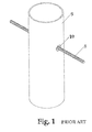
Referring now to FIGS. 1-3 , a typical grommet shown in a typical use is illustrated. In FIG. 1 , a post 9 of a handrail system is shown with a wire rope or the like 8 passing through the post 9 via hole 10. Without a grommet, the space between the wire 8 and the hole 10 may cause the wire 8 to deflect due to the excess space, and create sound as wind or other objects are applied to the wire rope 8. In FIG. 2 , a typical rubber grommet 13 is shown. The grommet includes raised flanges 14, a reduced center diameter 15 and an opening 16 for receiving the wire rope 8. FIG. 3 depicts the rubber grommet 13 installed in the holes 10 of a post 9 to insulate the wire 8. In order to install the grommet 13 into the post 9, one of the rubber flanges 14 of the typical grommet 13 must be collapsed in order to force it into hole 10, a difficult procedure. In this typical use, the grommet 13 must be installed into the holes 10 prior to the wire 8 being installed and cannot be installed after wire rope 8 has been positioned within post 9.
In use, the grommet 18, illustrated in FIGS. 7-8 is slid/snapped (positioned) in FIG. 7 over wire rope 8 and the helical cut 11 surrounds the wire 8, downward force engages the chamfered surface 6 to contact the wire 8. With force pushing parallel and downward onto the wire 8, the chamfered surface 6 allows the flange 12 to spread open and the wire 8 engages into the cannulation 17. The helical cut 11 of the cannulation 17 allows the grommet 18 to wrap around the wire 8 as it is sliding on. With a force parallel to the wire 8, the grommet 18 will slide into the cannulation 17 and onto the wire 8 as shown in cross-section in FIG. 8 .
As shown in FIG. 9 , the flange 12 rests against the post 9 and the grommet 18 stays in place due to the relief 2 (see FIGS. 7 and 8 ) pressing against the post thickness. The difference in the relief 2 diameter and hole 10 diameter place pressure on the grommet 18, thereby keeping the wire rope 8 from any lateral movement.
In the case of wire rope already installed into the post (such as that shown in FIG. 1 ), the longitudinal cannulation 17 rests against the wire rope 8. Further pressure on the flange 12 pushes the grommet 18 into the post hole 10 retained by the relief 2 and the flange 12. Since the inner diameter is slightly reduced, slight pressure is placed on the wire rope 8.
Although these teachings have been described with respect to various embodiments, it should be realized these teachings are also capable of a wide variety of further and other embodiments within the spirit and scope of the appended claims.
Claims (20)
1. A grommet comprising:
a body comprising a proximal end and a distal end, the body tapering from the proximal end to the distal end;
a relief adjacent to the proximal end of the body, an outer diameter of the relief being smaller than an outer diameter of the proximal end of the body;
a flange adjacent to the relief, an outer diameter of the flange being larger than the outer diameter of the proximal end of the body; and
a non-stepped, longitudinal cannulation extending from a proximal end of the flange to the distal end of the body, the cannulation being in communication with an exterior of the grommet through an opening extending from a proximal end of the flange to the distal end of the body, the opening defined by two opposing helical cuts formed in the body such that no portion of the helical cuts follows the taper of the body.
2. The grommet of claim 1 , wherein at least a portion of the opening is defined by two opposing chamfered surfaces.
3. The grommet of claim 1 , wherein the grommet is a unitary molded piece.
4. The grommet of claim 1 , wherein the grommet is comprised of a clear, rigid material.
5. The grommet of claim 4 , wherein the clear, rigid material is plastic.
6. The grommet of claim 4 , wherein the clear, rigid material is UV resistant.
7. The grommet of claim 1 , wherein the grommet is comprised of an opaque material.
8. The grommet of claim 7 , wherein the opaque material is metal or ceramic.
9. A method for securing a rope member using a grommet, the method comprising:
positioning a grommet over a rope member, the grommet comprising:
a body comprising a proximal end and a distal end, the body tapering from the proximal end to the distal end; a relief adjacent to the proximal end of the body, an outer diameter of the relief being smaller than an outer diameter of the proximal end of the body; a flange adjacent to the relief, an outer diameter of the flange being larger than the outer diameter of the proximal end of the body; and a non-stepped, longitudinal cannulation extending from a proximal end of the flange to the distal end of the body, the cannulation being in communication with an exterior of the grommet through an opening extending from a proximal end of the flange to the distal end of the body, the opening defined by two opposing helical cuts formed in the body such that no portion of the helical cuts follows the taper of the body;
pressing the flange onto the rope member, so that the rope member is forced into the flange opening;
pressing the body onto the rope member, so that the rope member is forced into the longitudinal cannulation; and
moving the grommet along the rope member so that the distal end of the body enters a bored hole, until the outer diameter of the relief is mounted in a rim of the hole.
10. A method for securing a rope member using a grommet, the method comprising:
positioning a grommet over a rope member, the grommet comprising:
a body comprising a proximal end and a distal end, the body tapering from the proximal end to the distal end; a relief adjacent to the proximal end of the body, an outer diameter of the relief being smaller than an outer diameter of the proximal end of the body; a flange adjacent to the relief, an outer diameter of the flange being larger than the outer diameter of the proximal end of the body; and a non-stepped, longitudinal cannulation extending from a proximal end of the flange to the distal end of the body, the cannulation being in communication with an exterior of the grommet through an opening extending from a proximal end of the flange to the distal end of the body, the opening defined by two opposing helical cuts formed in the body such that no portion of the helical cuts follows the taper of the body;
pressing the flange onto the rope member, so that the rope member is forced into the open portion of the flange;
pressing the body onto the rope member, so that the rope member is forced into the longitudinal cannulation; and
passing the rope member through a bored hole so that the distal end of the body enters the hole, until the outer diameter of the relief is mounted in a rim of the hole.
11. The method of claim 9 , wherein pressing the body onto the rope member comprises pressing the body both parallel to and downward onto the rope member.
12. The method of claim 9 , wherein the rope member is a wire rope.
13. The method of claim 9 , wherein the bored hole comprises a bored hole in a post of a handrail system.
14. The method of claim 13 , wherein, when the outer diameter of the relief is mounted in the rim of the hole, the flange rests against a surface of the post.
15. The method of claim 10 , wherein pressing the body onto the rope member comprises pressing the body both parallel to and downward onto the rope member.
16. The method of claim 10 , wherein the rope member is a wire rope.
17. The method of claim 10 , wherein the bored hole comprises a bored hole in a post of a handrail system.
18. The method of claim 17 , wherein, when the outer diameter of the relief is mounted in the rim of the hole, the flange rests against a surface of the post.
19. The grommet of claim 1 , wherein the flange is configured to expand when the flange opening is pressed over a rope member.
20. The grommet of claim 1 further comprising a rope member slidably received within the cannulation, the rope member extending outside of the grommet from the proximal end of the flange and from the distal end of the body.
Priority Applications (1)
| Application Number | Priority Date | Filing Date | Title |
|---|---|---|---|
| US14/603,470 US9784385B1 (en) | 2015-01-23 | 2015-01-23 | Grommet and method of use thereof |
Applications Claiming Priority (1)
| Application Number | Priority Date | Filing Date | Title |
|---|---|---|---|
| US14/603,470 US9784385B1 (en) | 2015-01-23 | 2015-01-23 | Grommet and method of use thereof |
Publications (1)
| Publication Number | Publication Date |
|---|---|
| US9784385B1 true US9784385B1 (en) | 2017-10-10 |
Family
ID=59982130
Family Applications (1)
| Application Number | Title | Priority Date | Filing Date |
|---|---|---|---|
| US14/603,470 Active 2035-06-14 US9784385B1 (en) | 2015-01-23 | 2015-01-23 | Grommet and method of use thereof |
Country Status (1)
| Country | Link |
|---|---|
| US (1) | US9784385B1 (en) |
Cited By (5)
| Publication number | Priority date | Publication date | Assignee | Title |
|---|---|---|---|---|
| WO2020035647A1 (en) * | 2018-08-14 | 2020-02-20 | Gripple Limited | Protector for a flexible elongate article |
| USD899905S1 (en) * | 2018-06-07 | 2020-10-27 | Donald Erik Kennedy | Concealment cap for cable tensioning mechanism |
| USD918020S1 (en) * | 2018-06-07 | 2021-05-04 | Donald Erik Kennedy | Concealment cap for cable tensioning mechanism |
| US11333270B2 (en) * | 2019-11-11 | 2022-05-17 | Bigrock Innovations Llc | Hose securing device |
| USD994468S1 (en) | 2020-11-11 | 2023-08-08 | Bigrock Innovations Llc | Hose securing device |
Citations (21)
| Publication number | Priority date | Publication date | Assignee | Title |
|---|---|---|---|---|
| US2034090A (en) * | 1934-05-25 | 1936-03-17 | Harry A Douglas | Wire terminal for electrical conductors |
| US2341922A (en) * | 1942-12-18 | 1944-02-15 | American Steel & Wire Co | Plug type socket |
| US2559759A (en) * | 1945-10-22 | 1951-07-10 | Illinois Tool Works | Grommet |
| US3033624A (en) * | 1959-11-23 | 1962-05-08 | Illinois Tool Works | Retainer bushing |
| US3164054A (en) * | 1962-04-13 | 1965-01-05 | Illinois Tool Works | Bushing with rib and shoulder means |
| US3220074A (en) * | 1963-09-03 | 1965-11-30 | Esco Corp | Self-swaging ferrule |
| US3470291A (en) * | 1966-06-30 | 1969-09-30 | Shell Oil Co | Forming thermoplastic articles |
| US3768115A (en) * | 1971-06-14 | 1973-10-30 | Ford Motor Co | Anti-rattle bushing |
| US3895879A (en) * | 1970-05-18 | 1975-07-22 | Reliable Electric Co | Combined post tensioning anchor and cable |
| US4066368A (en) * | 1975-08-05 | 1978-01-03 | A. B. Chance Company | Helical rod deadend having segmented rod receiving connector |
| US4074945A (en) * | 1976-05-06 | 1978-02-21 | Pennsylvania Wire Rope Corporation | Cable fastener assembly |
| US4304149A (en) * | 1979-09-06 | 1981-12-08 | Orscheln Co. | Synthetic plastic end fitting for brake cable assemblies |
| US4459722A (en) * | 1982-05-27 | 1984-07-17 | A. B. Chance Co. | Helical wire-conical wedge gripping device having conically formed rod ends between wedge and complementary socket therefor |
| US4546666A (en) * | 1984-10-09 | 1985-10-15 | Chrysler Corporation | Mounting structure for throttle control cable |
| US4619088A (en) * | 1984-03-23 | 1986-10-28 | Manufacturas De Acero Y Caucho S.A. | Stressed reinforcing tendon and structure including such a tendon |
| US4627762A (en) * | 1984-11-02 | 1986-12-09 | Douglas Marine S.R.L. | Device for rapidly fixing the ends of cables and the like |
| US4738155A (en) * | 1986-12-15 | 1988-04-19 | Ford Motor Company | Self-centering connector for vehicle accelerator pedal mounting lever |
| US4750886A (en) * | 1987-11-04 | 1988-06-14 | General Motors Corporation | Rod and retainer bushing |
| US5383905A (en) * | 1992-10-09 | 1995-01-24 | United States Surgical Corporation | Suture loop locking device |
| US8567151B2 (en) * | 2011-04-04 | 2013-10-29 | Grk Canada Ltd. | Toggle link deck to building connector |
| US20140138596A1 (en) * | 2012-11-17 | 2014-05-22 | George H. Ross | Cable railing |
-
2015
- 2015-01-23 US US14/603,470 patent/US9784385B1/en active Active
Patent Citations (23)
| Publication number | Priority date | Publication date | Assignee | Title |
|---|---|---|---|---|
| US2034090A (en) * | 1934-05-25 | 1936-03-17 | Harry A Douglas | Wire terminal for electrical conductors |
| US2341922A (en) * | 1942-12-18 | 1944-02-15 | American Steel & Wire Co | Plug type socket |
| US2559759A (en) * | 1945-10-22 | 1951-07-10 | Illinois Tool Works | Grommet |
| US3033624A (en) * | 1959-11-23 | 1962-05-08 | Illinois Tool Works | Retainer bushing |
| US3164054A (en) * | 1962-04-13 | 1965-01-05 | Illinois Tool Works | Bushing with rib and shoulder means |
| US3220074A (en) * | 1963-09-03 | 1965-11-30 | Esco Corp | Self-swaging ferrule |
| US3470291A (en) * | 1966-06-30 | 1969-09-30 | Shell Oil Co | Forming thermoplastic articles |
| US3895879A (en) * | 1970-05-18 | 1975-07-22 | Reliable Electric Co | Combined post tensioning anchor and cable |
| US3768115A (en) * | 1971-06-14 | 1973-10-30 | Ford Motor Co | Anti-rattle bushing |
| US4066368A (en) * | 1975-08-05 | 1978-01-03 | A. B. Chance Company | Helical rod deadend having segmented rod receiving connector |
| US4074945A (en) * | 1976-05-06 | 1978-02-21 | Pennsylvania Wire Rope Corporation | Cable fastener assembly |
| US4304149A (en) * | 1979-09-06 | 1981-12-08 | Orscheln Co. | Synthetic plastic end fitting for brake cable assemblies |
| US4459722A (en) * | 1982-05-27 | 1984-07-17 | A. B. Chance Co. | Helical wire-conical wedge gripping device having conically formed rod ends between wedge and complementary socket therefor |
| US4619088A (en) * | 1984-03-23 | 1986-10-28 | Manufacturas De Acero Y Caucho S.A. | Stressed reinforcing tendon and structure including such a tendon |
| US4546666A (en) * | 1984-10-09 | 1985-10-15 | Chrysler Corporation | Mounting structure for throttle control cable |
| US4627762A (en) * | 1984-11-02 | 1986-12-09 | Douglas Marine S.R.L. | Device for rapidly fixing the ends of cables and the like |
| US4671695A (en) * | 1984-11-02 | 1987-06-09 | Douglas Marine S.R.L. | Device for rapidly fixing the ends of cables and the like |
| US4738155A (en) * | 1986-12-15 | 1988-04-19 | Ford Motor Company | Self-centering connector for vehicle accelerator pedal mounting lever |
| US4750886A (en) * | 1987-11-04 | 1988-06-14 | General Motors Corporation | Rod and retainer bushing |
| US5383905A (en) * | 1992-10-09 | 1995-01-24 | United States Surgical Corporation | Suture loop locking device |
| US8567151B2 (en) * | 2011-04-04 | 2013-10-29 | Grk Canada Ltd. | Toggle link deck to building connector |
| US20140138596A1 (en) * | 2012-11-17 | 2014-05-22 | George H. Ross | Cable railing |
| US9249577B2 (en) * | 2012-11-17 | 2016-02-02 | George H. Ross | Cable railing |
Cited By (5)
| Publication number | Priority date | Publication date | Assignee | Title |
|---|---|---|---|---|
| USD899905S1 (en) * | 2018-06-07 | 2020-10-27 | Donald Erik Kennedy | Concealment cap for cable tensioning mechanism |
| USD918020S1 (en) * | 2018-06-07 | 2021-05-04 | Donald Erik Kennedy | Concealment cap for cable tensioning mechanism |
| WO2020035647A1 (en) * | 2018-08-14 | 2020-02-20 | Gripple Limited | Protector for a flexible elongate article |
| US11333270B2 (en) * | 2019-11-11 | 2022-05-17 | Bigrock Innovations Llc | Hose securing device |
| USD994468S1 (en) | 2020-11-11 | 2023-08-08 | Bigrock Innovations Llc | Hose securing device |
Similar Documents
| Publication | Publication Date | Title |
|---|---|---|
| US9784385B1 (en) | Grommet and method of use thereof | |
| US6523791B2 (en) | Cable duct coupler | |
| US7043801B2 (en) | Spring loaded and self-locking cable gripping apparatus | |
| US6241553B1 (en) | Connector for electrical cords and cables | |
| CA2122064C (en) | Optical fibre sheathing | |
| US8151519B2 (en) | Power sliding window assembly with caps | |
| US20150368962A1 (en) | Storm protection system | |
| WO2007098410A3 (en) | Ladder safety apparatus | |
| US5172878A (en) | Motion transmitting remote control assembly with improved retainers | |
| US20180044139A1 (en) | Drag rollers for escalators, moving walkways, and other conveyors | |
| US6727432B2 (en) | Grommet | |
| GB2580575A (en) | Securing device | |
| EP2333924B1 (en) | Wall bushing for feeding through cables, cable protection tubes or other conduits | |
| DE20314650U1 (en) | Taststeuerungseinrichtung | |
| US20120118631A1 (en) | Device for fixating cables with pull relief | |
| US20030019086A1 (en) | Grommet - wire harness retainer | |
| DE20218734U1 (en) | Corrugated pipe connection arrangement and corrugated pipe | |
| WO2008108421A1 (en) | Optical cable | |
| US7520101B2 (en) | Attachment of building elements | |
| IE47974B1 (en) | Improvements relating to pipe couplings | |
| PL1696165T3 (en) | Connector with fitting and pipe | |
| US20080296061A1 (en) | Connector for an electrical junction box | |
| US20080017334A1 (en) | Pop off nipple snap on fastener for sun shade technology | |
| WO2006127344A3 (en) | Handrail assembly | |
| US20180009358A1 (en) | Collapsible tailgate ladder and ramp |
Legal Events
| Date | Code | Title | Description |
|---|---|---|---|
| AS | Assignment |
Owner name: SUNCOR STAINLESS, INC., MASSACHUSETTS Free format text: ASSIGNMENT OF ASSIGNORS INTEREST;ASSIGNORS:STRIEBEL, PATRICK A.;STORRER, JAMES J.;REEL/FRAME:035827/0955 Effective date: 20150608 |
|
| STCF | Information on status: patent grant |
Free format text: PATENTED CASE |
|
| MAFP | Maintenance fee payment |
Free format text: PAYMENT OF MAINTENANCE FEE, 4TH YR, SMALL ENTITY (ORIGINAL EVENT CODE: M2551); ENTITY STATUS OF PATENT OWNER: SMALL ENTITY Year of fee payment: 4 |