US9788875B2 - Crimp with an insert to hold a cable - Google Patents
Crimp with an insert to hold a cable Download PDFInfo
- Publication number
- US9788875B2 US9788875B2 US13/002,621 US200813002621A US9788875B2 US 9788875 B2 US9788875 B2 US 9788875B2 US 200813002621 A US200813002621 A US 200813002621A US 9788875 B2 US9788875 B2 US 9788875B2
- Authority
- US
- United States
- Prior art keywords
- space
- insert
- distal
- lumen
- crimp
- Prior art date
- Legal status (The legal status is an assumption and is not a legal conclusion. Google has not performed a legal analysis and makes no representation as to the accuracy of the status listed.)
- Active, expires
Links
Images


Classifications
-
- A—HUMAN NECESSITIES
- A61—MEDICAL OR VETERINARY SCIENCE; HYGIENE
- A61B—DIAGNOSIS; SURGERY; IDENTIFICATION
- A61B17/00—Surgical instruments, devices or methods, e.g. tourniquets
- A61B17/56—Surgical instruments or methods for treatment of bones or joints; Devices specially adapted therefor
- A61B17/58—Surgical instruments or methods for treatment of bones or joints; Devices specially adapted therefor for osteosynthesis, e.g. bone plates, screws, setting implements or the like
- A61B17/68—Internal fixation devices, including fasteners and spinal fixators, even if a part thereof projects from the skin
- A61B17/82—Internal fixation devices, including fasteners and spinal fixators, even if a part thereof projects from the skin for bone cerclage
Definitions
- the invention relates generally to surgical methods and apparatus for treating bones and more particularly relates to a method and apparatus for bone fixation using cable for a bone cerclage technique.
- Bone cerclage procedures generally require that a wire or cable be looped around the bone and secured tightly.
- Present bone cerclage devices and methods require at least one incision adjacent the target portion of bone large enough to permit the insertion of bone cerclage tools used to insert and secure the cable around the bone.
- the present invention is directed to an apparatus for securing a cerclage member about a bone within a living body comprising a crimp including a first space extending longitudinally therethrough from a first space proximal opening to a first space distal opening, the first space sized and shaped to slidably receive a cerclage member therein and a second space extending substantially parallel to the first space from a second space proximal opening to a second space distal opening, the second space including a proximal portion sized and shaped to slidably receive the cerclage member therein and a distal portion decreasing in cross-sectional area from the second space distal opening to the proximal portion and an insert sized and shaped so that, when inserted into the second space distal opening adjacent to a cerclage member inserted therethrough, the decreasing cross-sectional area of the second space distal portion forces the insert laterally relative to a longitudinal axis of the second space pinching the cerclage member and locking the cerclage member against movement relative to the cri
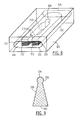
- FIG. 1 shows a perspective view of a crimp according to a first embodiment of the invention
- FIG. 2 shows a perspective view of an insert to be used with the crimp of FIG. 1 ;
- FIG. 3 shows a partial cross-sectional view of the crimp of FIG. 1 in an unlocked configuration
- FIG. 4 shows a partial cross-sectional view of the crimp of FIG. 1 in a locked configuration
- FIG. 5 shows a perspective view of a crimp according to a second embodiment of the invention
- FIG. 6 shows a partial cross-sectional view of the crimp of FIG. 5 in an unlocked configuration
- FIG. 7 shows a partial cross-sectional view of the crimp of FIG. 5 in a locked configuration
- FIG. 8 shows a perspective view of a crimp according to a third embodiment of the invention.
- FIG. 9 shows a perspective view of an insert to be used with the crimp of FIG. 8 ;
- FIG. 10 shows a partial cross-sectional view of the crimp of FIG. 8 in an unlocked configuration
- FIG. 11 shows a partial cross-sectional view of the crimp of FIG. 8 in a locked configuration.
- the present invention may be further understood with reference to the following description and the appended drawings, wherein like elements are referred to with the same reference numerals.
- the present invention relates generally to methods and devices for the stabilization and fixation of fractured bones and bone fragments via bone cerclage.
- the present invention relates to methods and devices for securing a cerclage wire or cable in a desired position looped around a target portion of bone.
- Embodiments of the present invention may also be employed with any of a plurality of bone treatment procedures requiring a bone cerclage.
- proximal and distal refer to direction along the cerclage cable with a first end of the cable being identified as the proximal end and a second end of the cable being identified as distal.
- Components of the crimp will then be described in relation to the direction in which the cable passes therethrough. For example, an opening to a lumen into which a distal end of the cable is inserted and against which a proximal end of the cable is held will be described as the proximal opening of the lumen. The opposite end of the lumen from which the distal end of the cable exits will be described as the distal opening of the lumen and the other elements of the crimp will be similarly identified.
- a crimping device 100 comprises a crimp 102 for receiving a cable 10 to be looped around a target portion of a bone (not shown).
- the crimp 102 comprises a cable lumen 108 and a crimp lumen 118 extending substantially parallel to one another along a longitudinal length of the crimp 102 .
- the distal end of a cable 10 is inserted into the cable lumen 108 via a proximal opening 114 thereof until an enlarged proximal end 12 thereof engages the portion of the crimp 102 surrounding the opening 114 preventing the cable 10 from being drawn further into the lumen 108 .
- the distal end of the cable 10 is then drawn from a distal opening 112 of the lumen 108 and looped around the bone to return to the crimp 102 .
- the distal end of the cable 10 is then inserted into the crimp lumen 118 via a proximal opening 124 until it passes out of the crimp lumen 118 via a distal opening 122 on the opposite side of the crimp 102 .
- An insert 126 is then placed over the distal end of the cable 10 and slid along the cable 10 until it enters the distal opening 122 .
- the crimp lumen 118 is tapered with a diameter thereof decreasing from a maximum at the distal opening 122 to a minimum proximally thereof.
- the insert 126 is forced proximally into the tapered distal portion of the crimp lumen 118 so that the inward taper of the distal portion of the crimp lumen 118 exerts radially inwardly directed force against the insert 126 which increases as the insert is forced further into the crimp lumen 118 .
- This force crushes the insert 126 against the cable 10 locking it in place over the cable 10 and preventing the cable 10 from moving proximally out of the opening 124 . This locks the cable 10 in the desired position around the bone and maintains the desired tension on the cable 10 .
- a proximal portion of the insert 126 may, for example, be sized and shaped to frictionally engage the tapered portion of the crimp lumen 118 .
- the tension of the cable 10 will draw the insert 126 further into the crimp lumen 118 securing it therein.
- the crimp 102 may be formed of any suitable biocompatible material as would be understood by those skilled in the art so long as this material exhibits rigidity sufficient to withstand the forces applied thereto when deployed in the body.
- Exemplary materials for the crimp 102 and insert 126 include, but are not limited to, stainless steel, titanium, titanium alloys, Polyetheretherketone (“PEEK”) or any combination thereof.
- the cable lumen 108 is formed with a size and shape permitting the selective insertion of the cable 10 therethrough with, for example, a substantially uniform diameter D 1 slightly greater than an outer diameter of the cable 10 .
- the lumen 108 is substantially circular.
- the cross-section of the cable lumen 108 may comprise any shape suited to a shape of the cable 10 .
- the crimp lumen 118 extends longitudinally from a proximal end 122 to a distal end 124 and is separated from the cable lumen 108 along a distal face 104 of the crimp 102 by a desired distance which may, for example, be selected to minimize the size of the crimp 102 while maintaining the structural integrity thereof.
- the crimp lumen 118 may for example, be substantially circular in cross-section, tapering from a diameter D 2 at the distal opening 122 to a diameter D 1 at a taper end point 116 located at any desired point within the crimp lumen 118 .
- the taper end point 116 is located midway between the distal opening 122 and the proximal opening 124 .
- the taper end point 116 may be located at any point enabling the insert 126 to be suitable crushed against the cable 10 , as will be described in greater detail hereinafter.
- the remainder of the crimp lumen 118 located distally of the taper end point 116 may comprise a uniform diameter D 1 .
- the diameter D 1 of the crimp lumen 118 may be substantially equal to the diameter D 1 of the cable lumen 108 as it will accommodate the same cable 10 . However, this is not necessary and the diameter D 1 may be any value sufficient to receive the cable 10 and small enough to prevent the passage of the insert 126 proximally therethrough.
- the insert 126 is formed as an elongated nail extending from an increased diameter head 128 at a distal end thereof to a slotted shaft 130 at a proximal end.
- a plurality of arms 132 spaced from one another circumferentially by a plurality of slots 134 extending proximally from the head 128 in a substantially cylindrical configuration defining a lumen 136 which extends through the insert 126 from a distal opening 138 to a proximal opening 140 .
- the lumen 136 is sized and shaped to slidably receive the cable 10 therethrough and, in an exemplary embodiment, has a diameter D 1 sufficient to slidably receive the cable 10 therethrough.
- a diameter of the head 128 may be made greater than a diameter D 2 of the proximal end 122 of the crimp lumen 118 to prevent insertion of the insert 126 thereinto beyond a predetermined distance. However, this is not necessary as the tapered portion of the crimp lumen 118 and the proximal portion of the crimp lumen 118 will be selected to prevent the passage of the insert 126 therethrough.
- FIGS. 3-4 sequentially depict the process by which the cable 10 is locked onto the crimp 102 in accordance with a first exemplary method of the present invention.
- the distal end of the cable 10 is inserted into the cable lumen 108 via the distal opening 114 until the enlarged proximal end 12 of the cable 10 prevents the cable 10 from being further inserted thereinto.
- Engagement of the enlarged proximal end 12 with the distal face 106 locks the distal end of the cable 10 against the crimp 102 .
- the cable 10 is then drawn out of the cable lumen 108 via the distal opening 112 and looped around the bone in a desired position.
- the distal end of the cable 10 is inserted into the crimp lumen 118 via the proximal opening 124 and passed therethrough to exit via the distal opening 122 .
- the distal end of the cable 10 is then inserted into the lumen 136 of the insert via the distal opening 138 and the insert 126 is slid proximally over the cable 10 .
- Tension may then be applied to the cable 10 until a desired level of tension is obtained and the insert 126 is slid proximally over the cable 10 until a proximal end of the insert 126 enters the distal opening 122 of the crimp lumen 118 , as shown in FIG. 3 . It is noted that, in the position shown in FIG.
- the insert 126 may be assembled within the distal opening 122 of the crimp lumen 118 in the position of FIG. 3 in the factory so that a user may thread the cable 10 through the crimp lumen 118 and the lumen 136 of the insert 126 in a single step.
- the insert 126 may be held in this position through a friction fit between the proximal end of the insert 126 and the distal end of the crimp lumen 118 .
- the cable 10 passes easily through the lumen 136 .
- the insert 126 may then be driven the desired distance into the crimp lumen 118 during the tensioning process. That is, the tensioning mechanism (not shown) may be abutted against the distal head 128 of the insert 126 so that, as tension on the cable 10 is increased, the tensioning mechanism applies increasing proximally directed force against the insert 126 forcing the insert 126 into the crimp lumen 118 to force the arms 130 radially inward into the lumen 136 pinching the cable 10 and locking the cable 10 in the desired position at the desired tension, as shown in FIG. 4 . As would be understood by those skilled in the art, this radially inward force may deform pinched portion of the cable 10 further aiding in locking the cable 10 in the desired position within the crimp 102 .
- a crimp 202 includes a distal end 222 of a crimp lumen 218 having a substantially D-shaped cross section.
- a cross section of the distal portion of the crimp lumen 218 comprises a substantially planar wall 220 connected to an arched portion 210 .
- a distal portion 218 ′ of the crimp lumen 218 tapers down in size from a maximum at the distal opening 222 to a taper end point 216 .
- a distal portion 218 ′′ of the crimp lumen 218 located proximally of the taper end point 216 has a substantially circular cross section similar to the crimp lumen 118 of FIGS. 1-4 .
- a cable lumen 208 extends longitudinally through the crimp 202 , substantially parallel to the crimp lumen 218 .
- a diameter D 1 of the cable lumen 208 and the proximal portion 218 ′′ of the crimp lumen 218 may be substantially equivalent to an outer diameter of the cable 10 .
- an exemplary insert 226 for use with the crimp 202 is sized and shaped to be inserted into the distal portion 218 ′ of the crimp lumen 218 and to be forced by the tapered shape thereof to apply a radially inward locking pressure against the cable 10 when driven into the distal portion 218 ′ of the crimp lumen 218 .
- the insert 226 is formed as a nail including an increased diameter head 228 extending radially outward from a distal end thereof and an elongated shaft 230 extending proximally from the head 228 .
- the shaft 230 may be formed as a substantially rectangular element with a thickness selected to reside easily beside the cable 10 within the distal opening 222 but which, when driven proximally into the tapered distal portion 218 ′, will be compressed against the cable 10 applying an increasing lateral force thereto until a desired locking position of the insert 226 is reached.
- the head 228 projects laterally from the insert 226 on a side thereof which faces away from the cable 10 (i.e., away from the arched side of the opening 222 ).
- a proximal surface of the head 228 is tapered at an angle ⁇ 1 substantially equivalent to a taper angle ⁇ 2 of the wall 220 so that, when the insert 226 is fully inserted into the crimp lumen 218 and a surface of the shaft 230 has been pushed against the tapered surface of the crimp lumen 218 , the tapered proximal surface of the head 228 lies substantially flush against a distal face 204 of the crimp 202 , as those skilled in the art will understand. Furthermore, engagement of the head 228 with the proximal face 204 prevents insertion of the insert 226 into the crimp lumen 218 beyond a desired predetermined distance. When in this position, as can be seen in FIG. 7 , the proximal end of the shaft 230 has pinched the cable 10 and compressed an adjacent surface thereof locking the cable 10 in the desired position and maintaining the desired tension thereon.
- FIGS. 6-7 sequentially depict the process by which the cable 10 is locked onto the crimp 202 .
- a distal end of the cable 10 is inserted into the cable lumen 208 via the proximal opening 214 until the enlarged proximal end 12 engages a proximal face 206 of the crimp 202 .
- the distal end of the cable 10 has passed out of the cable lumen 208 via the distal opening 212 .
- the cable 10 is then looped around the bone in a target position and the distal end of the cable is inserted into the crimp lumen 218 via the proximal opening 224 .
- the cable 10 is passed through the crimp lumen 218 to exit therefrom via the distal opening 222 .
- the distal end of the cable 10 is then coupled to any known tensioning mechanism (not shown) as would be understood by those skilled in the art and the insert 226 is inserted into the distal opening 222 adjacent to the cable 10 as shown in FIG. 6 .
- the tensioning mechanism may then be actuated to increase the tension on the cable 10 until a desired level has been reached.
- the tensioning mechanism may be abutted against the insert 226 so that, as the cable 10 is tensioned to the desired level, the tensioning mechanism may force the insert 226 into the crimp lumen 218 until the cable 10 has been locked in position at the desired tension as shown in FIG. 7 .
- a crimp 302 includes a single lumen 318 extending longitudinally therethrough from a proximal end 324 to a proximal end 324 .
- the lumen 318 is formed with a oblong cross-section and maintains a substantially uniform cross-sectional area.
- An insert 310 received within the lumen 318 includes sides which, in an initial configuration, are spaced from each of the lateral edges of the lumen 318 by spaces 326 and 328 sized to permit the cable 10 to pass through the lumen 318 on either side of the insert 310 as shown in FIG. 10 .
- the insert 310 is substantially U-shaped with a longitudinal length less than that of the crimp 302 .
- the insert 310 comprises a pair of substantially parallel arms 312 extending distally from a proximal joint 314 and separated from one another by a space 315 .
- a distal end 316 of each of the arms 312 is expanded to project into the space 315 forming a narrow entrance to the space 315 at the distal end thereof.
- a proximal end of the space 1315 forms a groove 308 which as described in more detail below, is sized and shaped to receive the proximal end of a wedge member 330 which is inserted into the space 315 to lock the cable within the crimp 302 .
- the wedge member 330 is substantially triangular with a proximal end formed as a plug 334 which may, for example, be substantially cylindrical, which is sized and shaped to be received in the groove 308 .
- the plug 334 is also sized so that it may be slid between the distal ends 316 of the arms 312 to force the arms from the initial configuration shown in FIGS. 8 and 10 to the locking configuration shown in FIG. 11 .
- the wedge member 330 is driven into the insert 310 with the plug 334 sliding between the distal ends 316 of the arms 312 , the tapered sides of the wedge member 330 force the arms 312 further from each other so that lateral sides thereof are forced into the spaces 326 and 328 driving the cable 10 against the walls of the lumen 318 and locking the cable 310 in position while maintaining the desired tension thereon.
- the width of the wedge member 330 increases from the proximal end to the distal end, the further proximally the wedge is driven into the space 315 , the further the distal ends 316 of the arms 312 are driven laterally from one another urging the laterally outer sides of the aims 312 into contact with the cable 10 locking both the proximal and distal portions thereof against the walls of the lumen 318 in the spaces 326 and 328 .
- a distal end of a cable 10 which in this embodiment may or may not include an enlarged proximal end, is inserted into the space 326 of the lumen 318 via the proximal opening 324 to exit the crimp 302 via the distal opening 322 .
- the cable 10 is then looped around the bone along a desired path and reinserted into the crimp 302 via the opening 324 . This time the distal end of the cable is passed through the space 328 to exit the distal opening 322 and connected to a tensioning mechanism.
- the wedge member 330 is driven into the space 315 by applying a proximally directed force to a distal end 332 thereof until the plug 334 is seated in the groove 308 locking the cable 10 to the crimp 302 in the desired position and with the desired tension.
Abstract
Description
Claims (16)
Priority Applications (1)
| Application Number | Priority Date | Filing Date | Title |
|---|---|---|---|
| US13/002,621 US9788875B2 (en) | 2008-07-29 | 2008-11-05 | Crimp with an insert to hold a cable |
Applications Claiming Priority (3)
| Application Number | Priority Date | Filing Date | Title |
|---|---|---|---|
| US8428908P | 2008-07-29 | 2008-07-29 | |
| PCT/US2008/082462 WO2010014119A1 (en) | 2008-07-29 | 2008-11-05 | Crimp with an insert to hold a cable |
| US13/002,621 US9788875B2 (en) | 2008-07-29 | 2008-11-05 | Crimp with an insert to hold a cable |
Related Parent Applications (1)
| Application Number | Title | Priority Date | Filing Date |
|---|---|---|---|
| PCT/US2008/082462 A-371-Of-International WO2010014119A1 (en) | 2008-07-29 | 2008-11-05 | Crimp with an insert to hold a cable |
Related Child Applications (1)
| Application Number | Title | Priority Date | Filing Date |
|---|---|---|---|
| US15/052,533 Continuation US9788877B2 (en) | 2008-07-29 | 2016-02-24 | Crimp with an insert to hold a cable |
Publications (2)
| Publication Number | Publication Date |
|---|---|
| US20110224676A1 US20110224676A1 (en) | 2011-09-15 |
| US9788875B2 true US9788875B2 (en) | 2017-10-17 |
Family
ID=40337494
Family Applications (2)
| Application Number | Title | Priority Date | Filing Date |
|---|---|---|---|
| US13/002,621 Active 2029-03-28 US9788875B2 (en) | 2008-07-29 | 2008-11-05 | Crimp with an insert to hold a cable |
| US15/052,533 Active 2028-11-06 US9788877B2 (en) | 2008-07-29 | 2016-02-24 | Crimp with an insert to hold a cable |
Family Applications After (1)
| Application Number | Title | Priority Date | Filing Date |
|---|---|---|---|
| US15/052,533 Active 2028-11-06 US9788877B2 (en) | 2008-07-29 | 2016-02-24 | Crimp with an insert to hold a cable |
Country Status (4)
| Country | Link |
|---|---|
| US (2) | US9788875B2 (en) |
| EP (1) | EP2320818B1 (en) |
| CA (1) | CA2731168C (en) |
| WO (1) | WO2010014119A1 (en) |
Cited By (3)
| Publication number | Priority date | Publication date | Assignee | Title |
|---|---|---|---|---|
| US10179016B1 (en) * | 2017-09-19 | 2019-01-15 | Cable Fix LLC | Apparatus, system, and method for crimping a cable for bone fixation |
| US10349996B2 (en) | 2015-12-07 | 2019-07-16 | Cable Fix LLC | Apparatus, system, and method for securing a tensioned cable through or around bone |
| US10925654B2 (en) | 2017-09-19 | 2021-02-23 | Cable Fix LLC | Apparatus, system, and method for crimping a cable for bone fixation |
Families Citing this family (15)
| Publication number | Priority date | Publication date | Assignee | Title |
|---|---|---|---|---|
| JP2014527847A (en) * | 2011-07-16 | 2014-10-23 | デピュイ・シンセス・プロダクツ・エルエルシーDePuy Synthes Products, LLC | Minimally invasive crimping element and cable for bone cerclage |
| JP5409973B1 (en) * | 2012-02-29 | 2014-02-05 | オリンパスメディカルシステムズ株式会社 | Thread fixing tool |
| US11839366B2 (en) | 2012-05-14 | 2023-12-12 | Kinamed, Inc. | High tension suture anchor |
| US20140058445A1 (en) * | 2012-05-14 | 2014-02-27 | Terry Mattchen | High tension suture anchor |
| US10765465B2 (en) | 2012-11-21 | 2020-09-08 | A&E Advanced Closure Systems, Llc | Tensioning instrument |
| US9561064B2 (en) | 2012-11-21 | 2017-02-07 | Pioneer Surgical Technology, Inc. | Bone plate system and method |
| US11446062B2 (en) | 2013-03-14 | 2022-09-20 | Kinamed, Inc. | Vector compression system |
| US10383658B2 (en) | 2013-03-14 | 2019-08-20 | Poly-4 Group, Lp | Vector compression system |
| US9999454B2 (en) | 2013-12-05 | 2018-06-19 | A&E Advanced Closure Systems, Llc | Bone plate system and method |
| US10314635B2 (en) | 2014-05-28 | 2019-06-11 | A&E Advanced Closure Systems, Llc | Tensioning instruments |
| US11079340B2 (en) | 2014-12-23 | 2021-08-03 | 3M Innovative Properties Company | Methods of monitoring wetness utilizing a resonant circuit |
| US10161895B2 (en) | 2014-12-23 | 2018-12-25 | 3M Innovative Properties Company | Electronic moisture sensor |
| AU2017210022B2 (en) | 2016-01-22 | 2021-05-13 | A&E Advanced Closure Systems, Llc | Bone plate having a connector and a connector for a surgical loop |
| WO2018022283A1 (en) | 2016-07-29 | 2018-02-01 | Pioneer Surgical Technology, Inc. | Surgical cable tensioner |
| WO2019055723A1 (en) * | 2017-09-15 | 2019-03-21 | Dsm Ip Assets, B.V. | Medical fixation device for polymer cables |
Citations (22)
| Publication number | Priority date | Publication date | Assignee | Title |
|---|---|---|---|---|
| US3879147A (en) * | 1972-11-06 | 1975-04-22 | Juan Coll Morell | Wedge for gripping a multi-ply cable |
| US3938902A (en) * | 1974-02-26 | 1976-02-17 | Juan Coll Morell | Connecting device for wires |
| US3952377A (en) * | 1974-01-25 | 1976-04-27 | Juan Coll Morell | Conical wedges for gripping multi-ply rope or cable |
| US4156574A (en) * | 1978-02-06 | 1979-05-29 | Boden Ogden W | Cord lock with self locking spring feelers |
| US4730087A (en) * | 1986-12-19 | 1988-03-08 | Amp Incorporated | Explosively-operated electrical connector |
| US5090923A (en) * | 1990-09-28 | 1992-02-25 | Burndy Corporation | Dedicated contact aid for connectors utilizing high speed installations |
| EP0596277A1 (en) | 1992-10-09 | 1994-05-11 | United States Surgical Corporation | Absorbable sternum closure buckle |
| EP0625336A2 (en) | 1993-04-21 | 1994-11-23 | AMEI TECHNOLOGIES Inc. | System and method for securing a medical cable |
| US5435044A (en) * | 1993-04-16 | 1995-07-25 | Yoshida Kogyo K.K. | Cord tightening device |
| DE19628147A1 (en) | 1996-07-12 | 1998-01-15 | Aesculap Ag & Co Kg | Surgical bone fixing device |
| US6099527A (en) * | 1998-04-30 | 2000-08-08 | Spinal Concepts, Inc. | Bone protector and method |
| US6277120B1 (en) * | 2000-09-20 | 2001-08-21 | Kevin Jon Lawson | Cable-anchor system for spinal fixation |
| US6589246B1 (en) * | 2001-04-26 | 2003-07-08 | Poly-4 Medical, Inc. | Method of applying an active compressive force continuously across a fracture |
| US6684585B2 (en) * | 2001-05-30 | 2004-02-03 | Robert Campbell | Method and apparatus for providing a visual indication of the tension applied to a tendon of a post-tension system |
| US7250054B2 (en) * | 2002-08-28 | 2007-07-31 | Smith & Nephew, Inc. | Systems, methods, and apparatuses for clamping and reclamping an orthopedic surgical cable |
| US20080208205A1 (en) * | 2007-02-26 | 2008-08-28 | Paul Edward Kraemer | Cable system and methods |
| US20090171357A1 (en) * | 2007-12-20 | 2009-07-02 | Medicineloge, Inc. | Collet fixation system |
| US20090248028A1 (en) * | 2008-03-26 | 2009-10-01 | Anthony Alexander | Systems and Methods of Anchoring Surgical Wires, Catheters, and other Medical Objects |
| US20090292317A1 (en) * | 2008-05-20 | 2009-11-26 | Zimmer Spine S.A.S. | System for stabilizing at least two vertebrae |
| US7846181B2 (en) * | 1998-12-30 | 2010-12-07 | Depuy Mitek, Inc. | Suture locking device |
| US20120130373A1 (en) * | 2009-07-31 | 2012-05-24 | Gilles Larroque-Lahitette | Bone fixing system |
| US20120215224A1 (en) * | 2011-02-17 | 2012-08-23 | Songer Matthew N | Cable system for surgical application |
-
2008
- 2008-11-05 CA CA2731168A patent/CA2731168C/en not_active Expired - Fee Related
- 2008-11-05 EP EP08876441.0A patent/EP2320818B1/en not_active Not-in-force
- 2008-11-05 WO PCT/US2008/082462 patent/WO2010014119A1/en active Application Filing
- 2008-11-05 US US13/002,621 patent/US9788875B2/en active Active
-
2016
- 2016-02-24 US US15/052,533 patent/US9788877B2/en active Active
Patent Citations (24)
| Publication number | Priority date | Publication date | Assignee | Title |
|---|---|---|---|---|
| US3879147A (en) * | 1972-11-06 | 1975-04-22 | Juan Coll Morell | Wedge for gripping a multi-ply cable |
| US3952377A (en) * | 1974-01-25 | 1976-04-27 | Juan Coll Morell | Conical wedges for gripping multi-ply rope or cable |
| US3938902A (en) * | 1974-02-26 | 1976-02-17 | Juan Coll Morell | Connecting device for wires |
| US4156574A (en) * | 1978-02-06 | 1979-05-29 | Boden Ogden W | Cord lock with self locking spring feelers |
| US4730087A (en) * | 1986-12-19 | 1988-03-08 | Amp Incorporated | Explosively-operated electrical connector |
| US5090923A (en) * | 1990-09-28 | 1992-02-25 | Burndy Corporation | Dedicated contact aid for connectors utilizing high speed installations |
| EP0596277A1 (en) | 1992-10-09 | 1994-05-11 | United States Surgical Corporation | Absorbable sternum closure buckle |
| US5356417A (en) * | 1992-10-09 | 1994-10-18 | United States Surgical Corporation | Absorbable sternum closure buckle |
| US5435044A (en) * | 1993-04-16 | 1995-07-25 | Yoshida Kogyo K.K. | Cord tightening device |
| EP0625336A2 (en) | 1993-04-21 | 1994-11-23 | AMEI TECHNOLOGIES Inc. | System and method for securing a medical cable |
| DE19628147A1 (en) | 1996-07-12 | 1998-01-15 | Aesculap Ag & Co Kg | Surgical bone fixing device |
| US5908421A (en) * | 1996-07-12 | 1999-06-01 | Aesculap Ag & Co. Kg | Surgical device for fixing bone elements |
| US6099527A (en) * | 1998-04-30 | 2000-08-08 | Spinal Concepts, Inc. | Bone protector and method |
| US7846181B2 (en) * | 1998-12-30 | 2010-12-07 | Depuy Mitek, Inc. | Suture locking device |
| US6277120B1 (en) * | 2000-09-20 | 2001-08-21 | Kevin Jon Lawson | Cable-anchor system for spinal fixation |
| US6589246B1 (en) * | 2001-04-26 | 2003-07-08 | Poly-4 Medical, Inc. | Method of applying an active compressive force continuously across a fracture |
| US6684585B2 (en) * | 2001-05-30 | 2004-02-03 | Robert Campbell | Method and apparatus for providing a visual indication of the tension applied to a tendon of a post-tension system |
| US7250054B2 (en) * | 2002-08-28 | 2007-07-31 | Smith & Nephew, Inc. | Systems, methods, and apparatuses for clamping and reclamping an orthopedic surgical cable |
| US20080208205A1 (en) * | 2007-02-26 | 2008-08-28 | Paul Edward Kraemer | Cable system and methods |
| US20090171357A1 (en) * | 2007-12-20 | 2009-07-02 | Medicineloge, Inc. | Collet fixation system |
| US20090248028A1 (en) * | 2008-03-26 | 2009-10-01 | Anthony Alexander | Systems and Methods of Anchoring Surgical Wires, Catheters, and other Medical Objects |
| US20090292317A1 (en) * | 2008-05-20 | 2009-11-26 | Zimmer Spine S.A.S. | System for stabilizing at least two vertebrae |
| US20120130373A1 (en) * | 2009-07-31 | 2012-05-24 | Gilles Larroque-Lahitette | Bone fixing system |
| US20120215224A1 (en) * | 2011-02-17 | 2012-08-23 | Songer Matthew N | Cable system for surgical application |
Cited By (3)
| Publication number | Priority date | Publication date | Assignee | Title |
|---|---|---|---|---|
| US10349996B2 (en) | 2015-12-07 | 2019-07-16 | Cable Fix LLC | Apparatus, system, and method for securing a tensioned cable through or around bone |
| US10179016B1 (en) * | 2017-09-19 | 2019-01-15 | Cable Fix LLC | Apparatus, system, and method for crimping a cable for bone fixation |
| US10925654B2 (en) | 2017-09-19 | 2021-02-23 | Cable Fix LLC | Apparatus, system, and method for crimping a cable for bone fixation |
Also Published As
| Publication number | Publication date |
|---|---|
| CA2731168C (en) | 2016-05-03 |
| US9788877B2 (en) | 2017-10-17 |
| US20110224676A1 (en) | 2011-09-15 |
| EP2320818B1 (en) | 2014-04-09 |
| CA2731168A1 (en) | 2010-02-04 |
| US20160166299A1 (en) | 2016-06-16 |
| WO2010014119A1 (en) | 2010-02-04 |
| EP2320818A1 (en) | 2011-05-18 |
Similar Documents
| Publication | Publication Date | Title |
|---|---|---|
| US9788877B2 (en) | Crimp with an insert to hold a cable | |
| EP2217164B1 (en) | Minimally invasive cerclage system | |
| AU2017200684B2 (en) | Flexible helical fixation device | |
| US7967821B2 (en) | Break-off screw extension removal tools | |
| JP5187809B2 (en) | Fastening system for internal fixation | |
| US6569186B1 (en) | Soft tissue screw and fixation device | |
| EP2421456B1 (en) | System for minimally invasive crimp and cable for bone cerclage | |
| JP2007252929A (en) | Fastening system for internal fixation | |
| US20200405329A1 (en) | Syndesmosis fixation and reconstruction system and method of using the same | |
| US10722229B2 (en) | Suture crimp plate | |
| EP3322367A1 (en) | Cable fixation device, instruments, and methods |
Legal Events
| Date | Code | Title | Description |
|---|---|---|---|
| AS | Assignment |
Owner name: SYNTHES (U.S.A.), PENNSYLVANIA Free format text: ASSIGNMENT OF ASSIGNORS INTEREST;ASSIGNOR:DELL'OCA, ALBERTO A. FERNANDEZ;REEL/FRAME:025612/0606 Effective date: 20081118 Owner name: SYNTHES USA, LLC, PENNSYLVANIA Free format text: CHANGE OF NAME;ASSIGNOR:SYNTHES (U.S.A.);REEL/FRAME:025612/0617 Effective date: 20081231 |
|
| AS | Assignment |
Owner name: DEPUY SYNTHES PRODUCTS, LLC, MASSACHUSETTS Free format text: CHANGE OF NAME;ASSIGNOR:HAND INNOVATIONS LLC;REEL/FRAME:030359/0036 Effective date: 20121231 Owner name: DEPUY SPINE, LLC, MASSACHUSETTS Free format text: ASSIGNMENT OF ASSIGNORS INTEREST;ASSIGNOR:SYNTHES USA, LLC;REEL/FRAME:030358/0945 Effective date: 20121230 Owner name: HAND INNOVATIONS LLC, FLORIDA Free format text: ASSIGNMENT OF ASSIGNORS INTEREST;ASSIGNOR:DEPUY SPINE, LLC;REEL/FRAME:030359/0001 Effective date: 20121230 |
|
| AS | Assignment |
Owner name: DEPUY SYNTHES PRODUCTS, INC., MASSACHUSETTS Free format text: CHANGE OF NAME;ASSIGNOR:DEPUY SYNTHES PRODUCTS, LLC;REEL/FRAME:035074/0647 Effective date: 20141219 |
|
| AS | Assignment |
Owner name: HAND INNOVATIONS LLC, FLORIDA Free format text: CORRECTIVE ASSIGNMENT TO CORRECT THE INCORRECT APPL. NO. 13/486,591 PREVIOUSLY RECORDED AT REEL: 030359 FRAME: 0001. ASSIGNOR(S) HEREBY CONFIRMS THE ASSIGNMENT;ASSIGNOR:DEPUY SPINE, LLC;REEL/FRAME:042621/0565 Effective date: 20121230 |
|
| AS | Assignment |
Owner name: DEPUY SPINE, LLC, MASSACHUSETTS Free format text: CORRECTIVE ASSIGNMENT TO CORRECT THE INCORRECT APPLICATION NO. US 13/486,591 PREVIOUSLY RECORDED ON REEL 030358 FRAME 0945. ASSIGNOR(S) HEREBY CONFIRMS THE ASSIGNMENT;ASSIGNOR:SYNTHES USA, LLC;REEL/FRAME:042687/0849 Effective date: 20121230 |
|
| STCF | Information on status: patent grant |
Free format text: PATENTED CASE |
|
| MAFP | Maintenance fee payment |
Free format text: PAYMENT OF MAINTENANCE FEE, 4TH YEAR, LARGE ENTITY (ORIGINAL EVENT CODE: M1551); ENTITY STATUS OF PATENT OWNER: LARGE ENTITY Year of fee payment: 4 |