US9790716B2 - Opposed hook sliding door lock - Google Patents
Opposed hook sliding door lock Download PDFInfo
- Publication number
- US9790716B2 US9790716B2 US14/885,366 US201514885366A US9790716B2 US 9790716 B2 US9790716 B2 US 9790716B2 US 201514885366 A US201514885366 A US 201514885366A US 9790716 B2 US9790716 B2 US 9790716B2
- Authority
- US
- United States
- Prior art keywords
- lock
- block
- pair
- operator
- hooks
- Prior art date
- Legal status (The legal status is an assumption and is not a legal conclusion. Google has not performed a legal analysis and makes no representation as to the accuracy of the status listed.)
- Expired - Fee Related
Links
Images


Classifications
-
- E—FIXED CONSTRUCTIONS
- E05—LOCKS; KEYS; WINDOW OR DOOR FITTINGS; SAFES
- E05C—BOLTS OR FASTENING DEVICES FOR WINGS, SPECIALLY FOR DOORS OR WINDOWS
- E05C9/00—Arrangements of simultaneously actuated bolts or other securing devices at well-separated positions on the same wing
-
- E—FIXED CONSTRUCTIONS
- E05—LOCKS; KEYS; WINDOW OR DOOR FITTINGS; SAFES
- E05B—LOCKS; ACCESSORIES THEREFOR; HANDCUFFS
- E05B65/00—Locks or fastenings for special use
- E05B65/08—Locks or fastenings for special use for sliding wings
- E05B65/0858—Locks or fastenings for special use for sliding wings comprising simultaneously pivoting double hook-like locking members
-
- E—FIXED CONSTRUCTIONS
- E05—LOCKS; KEYS; WINDOW OR DOOR FITTINGS; SAFES
- E05B—LOCKS; ACCESSORIES THEREFOR; HANDCUFFS
- E05B81/00—Power-actuated vehicle locks
- E05B81/02—Power-actuated vehicle locks characterised by the type of actuators used
- E05B81/04—Electrical
-
- E—FIXED CONSTRUCTIONS
- E05—LOCKS; KEYS; WINDOW OR DOOR FITTINGS; SAFES
- E05B—LOCKS; ACCESSORIES THEREFOR; HANDCUFFS
- E05B81/00—Power-actuated vehicle locks
- E05B81/54—Electrical circuits
-
- E—FIXED CONSTRUCTIONS
- E05—LOCKS; KEYS; WINDOW OR DOOR FITTINGS; SAFES
- E05C—BOLTS OR FASTENING DEVICES FOR WINGS, SPECIALLY FOR DOORS OR WINDOWS
- E05C3/00—Fastening devices with bolts moving pivotally or rotatively
- E05C3/002—Fastening devices with bolts moving pivotally or rotatively sliding in an arcuate guide or the like
-
- E—FIXED CONSTRUCTIONS
- E05—LOCKS; KEYS; WINDOW OR DOOR FITTINGS; SAFES
- E05C—BOLTS OR FASTENING DEVICES FOR WINGS, SPECIALLY FOR DOORS OR WINDOWS
- E05C3/00—Fastening devices with bolts moving pivotally or rotatively
- E05C3/12—Fastening devices with bolts moving pivotally or rotatively with latching action
- E05C3/124—Fastening devices with bolts moving pivotally or rotatively with latching action with latch under compression force between its pivot and the striker
-
- E—FIXED CONSTRUCTIONS
- E05—LOCKS; KEYS; WINDOW OR DOOR FITTINGS; SAFES
- E05C—BOLTS OR FASTENING DEVICES FOR WINGS, SPECIALLY FOR DOORS OR WINDOWS
- E05C3/00—Fastening devices with bolts moving pivotally or rotatively
- E05C3/12—Fastening devices with bolts moving pivotally or rotatively with latching action
- E05C3/16—Fastening devices with bolts moving pivotally or rotatively with latching action with operating handle or equivalent member moving otherwise than rigidly with the latch
- E05C3/22—Fastening devices with bolts moving pivotally or rotatively with latching action with operating handle or equivalent member moving otherwise than rigidly with the latch the bolt being spring controlled
- E05C3/30—Fastening devices with bolts moving pivotally or rotatively with latching action with operating handle or equivalent member moving otherwise than rigidly with the latch the bolt being spring controlled in the form of a hook
- E05C3/34—Fastening devices with bolts moving pivotally or rotatively with latching action with operating handle or equivalent member moving otherwise than rigidly with the latch the bolt being spring controlled in the form of a hook with simultaneously operating double bolts
-
- E—FIXED CONSTRUCTIONS
- E05—LOCKS; KEYS; WINDOW OR DOOR FITTINGS; SAFES
- E05B—LOCKS; ACCESSORIES THEREFOR; HANDCUFFS
- E05B17/00—Accessories in connection with locks
- E05B17/20—Means independent of the locking mechanism for preventing unauthorised opening, e.g. for securing the bolt in the fastening position
- E05B17/2007—Securing, deadlocking or "dogging" the bolt in the fastening position
- E05B17/2026—Securing, deadlocking or "dogging" the bolt in the fastening position automatic, i.e. actuated by a closed door position sensor
-
- E—FIXED CONSTRUCTIONS
- E05—LOCKS; KEYS; WINDOW OR DOOR FITTINGS; SAFES
- E05B—LOCKS; ACCESSORIES THEREFOR; HANDCUFFS
- E05B47/00—Operating or controlling locks or other fastening devices by electric or magnetic means
- E05B47/0001—Operating or controlling locks or other fastening devices by electric or magnetic means with electric actuators; Constructional features thereof
- E05B47/0012—Operating or controlling locks or other fastening devices by electric or magnetic means with electric actuators; Constructional features thereof with rotary electromotors
-
- E—FIXED CONSTRUCTIONS
- E05—LOCKS; KEYS; WINDOW OR DOOR FITTINGS; SAFES
- E05B—LOCKS; ACCESSORIES THEREFOR; HANDCUFFS
- E05B63/00—Locks or fastenings with special structural characteristics
- E05B63/18—Locks or fastenings with special structural characteristics with arrangements independent of the locking mechanism for retaining the bolt or latch in the retracted position
- E05B63/185—Preventing actuation of a bolt when the wing is open
-
- E—FIXED CONSTRUCTIONS
- E05—LOCKS; KEYS; WINDOW OR DOOR FITTINGS; SAFES
- E05C—BOLTS OR FASTENING DEVICES FOR WINGS, SPECIALLY FOR DOORS OR WINDOWS
- E05C19/00—Other devices specially designed for securing wings, e.g. with suction cups
- E05C19/02—Automatic catches, i.e. released by pull or pressure on the wing
- E05C19/026—Automatic catches, i.e. released by pull or pressure on the wing with a keeper caught between two pivoting bolts
-
- E—FIXED CONSTRUCTIONS
- E05—LOCKS; KEYS; WINDOW OR DOOR FITTINGS; SAFES
- E05C—BOLTS OR FASTENING DEVICES FOR WINGS, SPECIALLY FOR DOORS OR WINDOWS
- E05C9/00—Arrangements of simultaneously actuated bolts or other securing devices at well-separated positions on the same wing
- E05C9/04—Arrangements of simultaneously actuated bolts or other securing devices at well-separated positions on the same wing with two sliding bars moved in opposite directions when fastening or unfastening
- E05C9/041—Arrangements of simultaneously actuated bolts or other securing devices at well-separated positions on the same wing with two sliding bars moved in opposite directions when fastening or unfastening with rack and pinion mechanism
Definitions
- sliding door locks are installed on sliding doors to lock the door to the door frame for security purposes.
- sliding door locks include one or more locking elements in the form of hooks that may be pivoted into an associated keeper or strike on the door.
- these locking elements are disposed within a lock housing when unlocked and extend from the housing when locked. Additionally, the locking elements are disposed proximate a center of the door height. Such placement is generally well-known by intruders, who often concentrate their breaching efforts against the center of the door to defeat the lock. Additionally, single hook sliding door locks can often be defeated by lifting the door from its sliding track and pulling the hook out of the keeper.
- the technology described herein is a high strength, secure sliding door lock with one or more locking points.
- Each locking mechanism has opposing hooks with a hook block between the hooks for exceptionally high locking strength and security.
- a single separate lock operator between the individual locks operates the lock system.
- the technology relates to a sliding door lock system having: a centrally-disposed operator having: a casing; a trigger retractably extending from the casing; and an operator mechanism disposed in the casing and operatively engaged with the trigger; a lock disposed remote from the operator, the lock having: a housing; a pair of opposed locking hooks extending from the housing; and a spring biasing each of the pair of opposed locking hooks into an unlocked position; and a block pivotably connected to the housing, wherein the block is configured to engage the pair of opposed locking hooks when the pair of opposed locking hooks are in a locked position; and an elongate member operably connecting the operator mechanism to the block.
- the pair of opposed locking hooks each includes a contact face configured to contact a strike so as to pivot each of the pair of opposed locking hooks into the locked position.
- the lock further includes a block spring configured to bias the block into an engaged position where the block engages the pair of opposed locking hooks while in the locked position.
- the lock further includes a release lever configured to oppose a force generated by the block spring, so as to hold the block in a disengaged position.
- the elongate mechanism is a tension member configured to be substantially slack when the lock is in the locked position and configured to be substantially taut when the lock is in the unlocked position.
- the operator mechanism includes: at least one rack; and a rotatable element engaged with the rack, wherein a rotation of the rotatable element moves the at least one rack between a first position and a second position.
- the operator mechanism further includes a take-up mechanism connecting the at least one rack to the elongate member.
- the take-up mechanism further includes a spring-controlled linkage.
- the technology relates to a lock having: a housing; a pair of opposed locking hooks extending from the housing, wherein the pair of opposed locking hooks each include a contact face configured to contact a strike so as to pivot each of the pair of opposed locking hooks into a locked position; and a spring biasing each of the pair of opposed locking hooks into an unlocked position.
- the lock further includes: a block pivotably connected to the housing, wherein the block is configured to engage the pair of opposed locking hooks in the locked position.
- the pair of opposed locking hooks each includes a detent for receiving at least a portion of the block.
- a release lever is configured to pivot so as to move the block from an engaged position to a disengaged position.
- a pivoting movement of the release lever is controlled by an elongate element extending into the housing from an exterior of the housing.
- a pivoting movement of the release lever is controlled by a motor disposed within the housing.
- the lock further includes the motor.
- the technology in another aspect, relates to a lock system having: a casing; and an operator mechanism disposed in the casing; a first housing disposed remote from the casing; a lock mechanism disposed in the first housing; and a pair of first opposing hooks extending from the first housing in both an unlocked position and a locked position, wherein each of the pair of first opposing hooks each includes a contact face configured to engage a strike so as to pivot each of the pair of first opposing hooks from the unlocked position to the locked position.
- the lock system further includes a block configured to releasably engage a detent in each of the pair of first opposing hooks so as to secure the pair of first opposing hooks in the locked position.
- the block is movable based on an actuation of the operator mechanism.
- the lock system further includes a tension element, wherein the actuation of the operator mechanism transfers movement to the block via the tension element.
- the lock system further includes a motor, wherein the actuation of the operator mechanism sends a signal to the motor.
- FIG. 1 depicts side sectional view of a door frame, including an opposed hook lock system, in an unlocked configuration.
- FIG. 1A depicts an enlarged side sectional view of the lock of FIG. 1 , in an unlocked configuration.
- FIG. 1B depicts an enlarged side sectional view of the lock operator of FIG. 1 , in a non-activated configuration.
- FIG. 2 depicts side sectional view of a door frame, including the opposed hook lock system of FIG. 1 , in a locked configuration.
- FIG. 2A depicts an enlarged side sectional view of the lock of FIG. 2 , in a locked configuration.
- FIG. 2B depicts an enlarged side sectional view of the lock operator of FIG. 2 , in an activated configuration.
- FIG. 3 depicts an enlarged side view of a lock in accordance with another example of the present technology.
- FIG. 4 depicts a schematic diagram of an electronic lock system in accordance with another example of the present technology.
- the design geometry of the proposed dual hooks is significantly different than the geometries normally used for lock mechanisms for sliding doors.
- current sliding door locks have weak pivoting single-point hooks for locking.
- the present lock utilizes, in certain examples, stronger dual hooks, larger diameter rivet pins, a robust hook blocking mechanism, and adjustable engaging lock strikes.
- the centrally-located lock operator that controls the remote dual hook locks is designed to release the individual locks above and below the lock operator by disengaging a locking block from engagement with the latched hooks.
- the operator releases the locks with a spring-loaded mechanism that pulls a tension member to each lock.
- the spring-loaded mechanism may be configured for over-travel, which simplifies lock installation, adjustment, and release timing.
- the dual hooks on each lock engage individual frame-mounted strikes when the door is closed, causing them to rotate and wrap around each frame-mounted strike. Lock release adjustments can be adjusted from the edge of the door panel without removing the lock system from the door panel.
- the lock operator may be controlled by an interior rotating handle or standard thumb turn and key cylinder mounted on typical sliding door hardware.
- Rotating sliding door handles are described in U.S. Patent Application Publication No. 2013/0334829, the disclosure of which is hereby incorporated by reference herein in its entirety.
- the lock hooks may be pivoted by a motor that is signaled to operate as described herein.
- the rotating handle (or thumb turn or key) turns the operating cam pinion in the lock operator by, in certain embodiments, 70 degrees to the unlocked position.
- the cam may rotate by, e.g., 90 degrees to the unlocked position. Other angles of rotation are contemplated.
- the lock operator pulls taut the tension members between the operator and each lock. As the tension member tightens, the hook block rotates out of position, releasing the hooks and unlocking the door. With the tension members taut and the hook block retracted, the door can be pulled away from the frame such that the dual locks automatically unlatch.
- the trigger release on the lock operator contacts the frame. Additionally, the opposing hooks at each lock contact the frame strikes and pivot so as to wrap around the strike in the locked position. Once in the closed position, the operator cam pinion in the lock operator is rotated so as to lock the door. Rotation may be performed by the rotating handle, thumb turn, or the key.
- FIG. 1 depicts side sectional view of a door frame F, including an opposed hook lock system 100 , in an unlocked configuration.
- the lock system 100 is installed in a sliding door D, but in other embodiments, the lock system 100 may be installed in the frame F.
- a plurality of strikes 102 or keepers are installed on the frame F, but may also be installed on the door D if the lock system 100 is installed on the frame F.
- the strikes 102 include a raised center 104 that the lock system 100 (specifically, opposed hooks thereof) may grip as described below.
- the lock system 100 includes a centrally-disposed lock operator 106 and one or more remotely-disposed locks 108 . Each of the lock operator 106 and remotely-disposed locks 108 are described in more detail herein.
- the lock operator 106 includes a casing 110 having an operator mechanism (depicted generally as 112 ) disposed therein.
- the casing 110 is held together with a plurality of case rivets, several of which acting as pivots or anchors for various components of the operator mechanism 112 .
- One or more elongate members 128 extend from the lock casing 110 at each end and extend to each lock 108 .
- Guides 109 in the casing 110 enable connection to a sliding door handle or escutcheon (not shown).
- the guides 109 may be through-holes for receiving escutcheon plate set screws.
- a face plate 111 may define one or more openings for a release trigger 116 to protrude, or to allow access to elements that enable adjustment of the internal elements of the operator mechanism 112 .
- the operator mechanism 112 is controlled by and includes an operating cam pinion 114 .
- One example of a particular configuration of the operator mechanism 112 is depicted below, which receives input from a rotating handle, thumb turn, or key, as well as the release trigger 116 .
- the operating mechanism 112 moves a spring-loaded take-up mechanism 152 to extend or retract one or more elongate members 128 .
- the elongate members 128 are tension members (such as cables, wires, or chains)
- the spring-loaded take-up mechanism 152 may tighten or loosen the tension members 128 .
- the release trigger 116 enables actuation of the operator mechanism 112 (more specifically, actuation of the operating cam pinion 114 , as described below).
- the release trigger 116 projects out of the casing face plate 111 .
- the release trigger 116 rotates into a position allowing the rack 148 to extend. If the door D is open, the release trigger 116 restricts the motion of the rack 148 , thus preventing rotation of the operating cam pinion 114 .
- the release trigger 116 prevents the operator mechanism 112 from functioning when the door D is open. As such, the release trigger 116 acts as an anti-slam device, preventing the hooks 122 from being actuated into a closed position when the door D is open.
- Each lock 108 includes a housing 118 that contains a lock mechanism (depicted generally as 120 ).
- a pair of pivoting hooks 122 project from the housing 118 in both the unlocked and latched/locked positions (as depicted in FIGS. 2 and 2A ).
- the lock mechanism 120 includes a block 124 that is configured to engage the hooks 122 when the hooks 122 are in the latched position. Once so engaged, the lock system 100 is locked.
- a block release lever 126 is configured to move the block 124 between a disengaged position and an engaged position and is connected to the operator mechanism 112 via an elongate element or member 128 , as described below.
- the casing 110 is discrete from the housings 118 and the elongate member 128 is disposed within a slot 130 formed in the door D that may be covered by a face plate 132 .
- This configuration allows the lock system 100 to be field-modified to be fitted into doors D having differing heights.
- the lock system 100 may be disposed in a single housing (that is, the casing 110 and housings 118 may be integrated into a single housing). In such a case, the operator mechanism 112 is still disposed remote from the lock mechanism 120 , in that the two mechanisms are connected by elongate members 128 .
- FIGS. 1A, 1B, 2A, and 2B depict upper locks 108 of the lock system 100 .
- Lower locks 108 are not depicted, but operation thereof would be apparent to a person of skill in the art.
- upper and lower locks 108 are mirror images of each other.
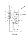
- FIG. 1A depicts an enlarged side sectional view of the lock 108 of FIG. 1 , in the unlocked configuration.
- the lock housing 118 includes two hooks 122 extending therefrom in both the unlocked position (depicted in FIG. 1A ) and the latched/locked position (depicted in FIG. 2A ).
- the hooks 122 are configured to pivot around rivets 134 , which are secured to the housing 118 and are biased by compression springs 136 into the unlocked position.
- springs 136 may be torsion springs disposed about rivets 134 .
- a block spring 138 applies a biasing force F against a block lever 141 , movement of which is prevented by a release lever 126 positioned as depicted.
- the elongate member 128 such as a tension member, is connected to the release lever 126 .
- FIG. 1B depicts an enlarged side sectional view of the lock operator 106 of FIG. 1 , in a non-activated configuration.
- the release trigger 116 extends from the lock casing 110 .
- a stop pin 142 is connected to the rack 148 .
- a position of the stop pin 142 in a slot 144 defined by the release trigger 116 prevents actuation of the operating cam pinion 114 , which in turn prevents movement of the block 124 (depicted in FIG. 1A ).
- a spring 146 biases the release trigger 116 into the extended position.
- the operating cam pinion 114 is engaged with two racks 148 .
- the lock mechanism 112 also includes two spring-loaded take-up mechanisms that extend between the racks 148 and the elongate members 128 .
- These take-up mechanisms include a spring-controlled linkage 153 that allows the rack 148 to over-travel when the operating cam pinion 114 is turned (e.g., 70 degrees, 90 degrees, etc.) to unlock and lock the locks 108 .
- a compression spring 150 controls maximum movement of the linkage 153 .
- One or more screws may be utilized to lock the elongate member 128 in place at a point of connection to the take-up mechanism (specifically, to the linkage 153 ). These screws may also be used to adjust tension of the elongate members 128 .
- the elongate members 128 that may be substantially taut when the operator mechanism 112 is in the non-activated configuration depicted in FIGS. 1-1B .
- FIG. 2 depicts side sectional view of a door frame F, including the opposed hook lock system 100 of FIG. 1 , in a locked configuration.
- a number of components depicted in FIG. 2 are described above with regard to FIGS. 1-1B and as such, are not described further.
- portions of each hook 122 contact the raised center 104 of each strike 102 . This contact forces pivoting of the hooks 122 until they are engaged with the strike 102 .
- the door D With the hooks 122 engaged with the strike 102 , the door D is passively latched. That is, by contacting the hooks 122 and the strikes 102 , the hooks 122 grip the strikes 102 , without any active action on the part of the person sliding the door D.
- the blocks 124 must be engaged with the hooks 122 , which in certain examples, requires an active action on the part of the user (rotating a handle or thumb turn, for example). Locking of the lock system 100 by engaging the blocks 124 with the hooks 122 is performed as described in more detail below.
- FIG. 2A depicts an enlarged side sectional view of the lock 108 of FIG. 2 , in the locked configuration.
- the hooks 122 passively engage the strike 102 .
- the hooks 122 each include leading contact faces or surfaces 152 . As these contact faces 152 contact the center portion 104 of the strike 102 , the hooks 122 rotate about the rivets 134 , in opposition to the forces applied by the compression springs 136 , so as latch to the strikes 102 .
- the lock system 100 is not locked until the block 124 is engaged with detents 154 in the hooks 122 .
- the elongate member 128 is moved M, which causes the release lever 126 to pivot, due to the force F generated by the block spring 138 .
- the release lever 126 pivots P, the block 124 is engaged with the detents 154 so as to lock the lock 108 , preventing the door D from being pulled open. Movement of the elongate member 128 is described below.
- FIG. 2B depicts an enlarged side sectional view of the lock operator of FIG. 2 , in an activated configuration.
- the release trigger 116 has contacted the door frame F and is biased against the force of the compression spring 146 into the casing 110 .
- This movement changes a position of the stop pin 142 relative to the slot 144 , therefor allowing the rack 148 to move when the operating cam pinion 114 is rotated (e.g., by the turning of a handle or thumb turn).
- dual racks 148 are used, such that rotation of the operating cam pinion 114 moves both racks 148 .
- the linkages 153 move as well, which in turn moves the elongate members 128 towards the lock 108 .
- FIG. 3 depicts an enlarged side view of a lock 208 in accordance with another example of the present technology.
- the lock 208 of FIG. 3 includes a motor 260 that is used to actuate the block 224 into and out of the engaged position depicted in FIG. 3 .
- the motor 260 includes an output shaft 262 and output gear 264 that rotates therewith.
- the output gear 264 is engaged with a lead screw gear 266 that is connected to a lead screw 268 .
- Rotation of the lead screw 268 advances and retracts an elongate nut 270 that is connected to either or both of the release lever 226 and the block lever 241 to engage or disengage the block 224 .
- the lock 208 operates similarly to the non-motorized locks depicted elsewhere herein. That is, the hooks 222 are biased by springs 236 , contact faces 252 of the hooks 222 contact the strike so as latch the hooks 222 , and so on.
- the lock 208 may also include a manual release lever 272 , which may be engaged with the block 224 . In the event of a power failure, an actuator 272 connected to a thumb turn or other element disposed on a surface of the door may be turned so as to pivot the manual release lever 272 . This pivoting disengages the block 224 from the hooks 222 , thus allowing the door to be opened.
- FIG. 4 depicts a schematic diagram of an electronic lock system 300 in accordance with another example of the present technology.
- the lock system 300 includes a lock operator 302 and a remotely-disposed lock 304 .
- the lock operator 302 may include a number of the same components as described with regard to the lock operators described elsewhere herein.
- the lock operator 302 includes additional sensors, actuators, and other components that enable control of the remotely-disposed lock 304 .
- the operator 302 may include a controller 306 that receives signals from the various other components and sends signals to the motor controller 308 associated with the motor 310 .
- the motor 310 can engage and disengage the locking block as described above with regard to FIG. 3 , for example.
- a number of sensors associated with the operator 302 are depicted.
- a release trigger sensor 312 may detect a position of the release trigger and send a signal to the controller 306 when the release trigger is retracted into the housing (indicating engagement of the door and the frame, as described elsewhere herein).
- a signal from the release trigger sensor 312 may be a threshold requirement, allowing activation of the lock (e.g., actuation of the motor 310 ) only when an appropriate signal from the release trigger sensor 312 is received.
- Other sensors that depict positions or conditions of various components of the operator and lock are depicted.
- a position sensor 314 may detect a position of a handle or thumb turn (or the operating cam pinion associated therewith).
- the controller 306 may send a signal to the motor controller 308 to activate the motor 310 .
- An RFID sensor 316 may detect the presence of an RFID chip contained in a key used to actuate the operating cam pinion and send an appropriate signal.
- Sensor 316 may also be associated with a keyless entry system, such as the KEVO Bluetooth Electronic Lock available from Kwikset. Other types of sensors are contemplated. Signals are sent between the operator 302 and lock 304 via a wired or wireless connection 318 . Additionally, powered components of the operator 302 and lock 304 may be powered by on board or remote batteries or by the building supply power.
- a single lock and a single lock operator may be used on a door.
- multiple locks and one or more lock operators can be utilized. It is contemplated that the various components and configurations depicted with regard to the locks disclosed herein, as well as modifications thereof envisioned by a person of ordinary skill in the art, are interchangeable.
- the various elements of the locks depicted herein may be manufactured of any materials typically used in door hardware/lock manufacture. Such materials include, but are not limited to, cast or machined steel, stainless steel, brass, titanium, etc. Material selection may be based, in part, on the environment in which the lock is expected to operate, material compatibility, manufacturing costs, product costs, etc. Additionally, some elements of the lock may be manufactured from high-impact strength plastics. Such materials may be acceptable for applications where robust security is less critical, or when a secondary, stronger material is utilized in conjunction with the plastic part.
Abstract
Description
Claims (11)
Priority Applications (1)
| Application Number | Priority Date | Filing Date | Title |
|---|---|---|---|
| US14/885,366 US9790716B2 (en) | 2014-10-16 | 2015-10-16 | Opposed hook sliding door lock |
Applications Claiming Priority (2)
| Application Number | Priority Date | Filing Date | Title |
|---|---|---|---|
| US201462064859P | 2014-10-16 | 2014-10-16 | |
| US14/885,366 US9790716B2 (en) | 2014-10-16 | 2015-10-16 | Opposed hook sliding door lock |
Publications (2)
| Publication Number | Publication Date |
|---|---|
| US20160108650A1 US20160108650A1 (en) | 2016-04-21 |
| US9790716B2 true US9790716B2 (en) | 2017-10-17 |
Family
ID=54365401
Family Applications (1)
| Application Number | Title | Priority Date | Filing Date |
|---|---|---|---|
| US14/885,366 Expired - Fee Related US9790716B2 (en) | 2014-10-16 | 2015-10-16 | Opposed hook sliding door lock |
Country Status (3)
| Country | Link |
|---|---|
| US (1) | US9790716B2 (en) |
| CA (1) | CA2964792A1 (en) |
| WO (1) | WO2016061473A1 (en) |
Cited By (20)
| Publication number | Priority date | Publication date | Assignee | Title |
|---|---|---|---|---|
| US20180245384A1 (en) * | 2017-02-24 | 2018-08-30 | Randall L. Shipley | Double throw window lock |
| US20180313116A1 (en) * | 2017-05-01 | 2018-11-01 | Amesbury Group, Inc. | Modular multi-point lock |
| US10662675B2 (en) | 2017-04-18 | 2020-05-26 | Amesbury Group, Inc. | Modular electronic deadbolt systems |
| US10760303B2 (en) * | 2016-03-28 | 2020-09-01 | Hoppe Holding Ag | Multi-point lock with single actuation and mishandling device and self-aligning engagement |
| US20200332576A1 (en) * | 2019-04-18 | 2020-10-22 | Rockwell Security, Inc. | Multi-pocket lock set |
| US10968661B2 (en) | 2016-08-17 | 2021-04-06 | Amesbury Group, Inc. | Locking system having an electronic deadbolt |
| US10982477B2 (en) * | 2017-06-09 | 2021-04-20 | Endura Products, Llc | Sliding door unit and components for the same |
| US11021894B1 (en) | 2017-11-14 | 2021-06-01 | Smart Armor Protected, LLC | Power-activated cam lock |
| EP3795783A3 (en) * | 2019-09-18 | 2021-07-07 | WILKA SCHLIESSTECHNIK GmbH | Auxiliary lock for multipoint locking |
| US11066850B2 (en) | 2017-07-25 | 2021-07-20 | Amesbury Group, Inc | Access handle for sliding doors |
| US20210230908A1 (en) * | 2018-05-24 | 2021-07-29 | Hawa Sliding Solutions Ag | Lock, fitting, strike plate and closing device for sliding doors and sliding door system |
| US11105120B2 (en) * | 2016-08-30 | 2021-08-31 | Sargent Manufacturing Company | Mortise lock with multi-point latch system |
| US11401735B2 (en) * | 2019-05-29 | 2022-08-02 | Jack Schonberger | Sliding door latch systems and method |
| US11441333B2 (en) | 2018-03-12 | 2022-09-13 | Amesbury Group, Inc. | Electronic deadbolt systems |
| US11549285B2 (en) * | 2018-12-03 | 2023-01-10 | Assa Abloy New Zealand Limited | Lock assembly |
| US11661771B2 (en) | 2018-11-13 | 2023-05-30 | Amesbury Group, Inc. | Electronic drive for door locks |
| US11692371B2 (en) * | 2017-04-06 | 2023-07-04 | Pella Corporation | Fenestration automation systems and methods |
| US11739588B2 (en) * | 2017-05-12 | 2023-08-29 | Iph International Pty Ltd | Security door system |
| US11828103B1 (en) * | 2019-11-25 | 2023-11-28 | WireCrafters, LLC | Door assembly with removable lockbox |
| US11834866B2 (en) | 2018-11-06 | 2023-12-05 | Amesbury Group, Inc. | Flexible coupling for electronic deadbolt systems |
Families Citing this family (8)
| Publication number | Priority date | Publication date | Assignee | Title |
|---|---|---|---|---|
| US8348308B2 (en) | 2008-12-19 | 2013-01-08 | Amesbury Group, Inc. | High security lock for door |
| CN104718339B (en) | 2012-08-31 | 2016-11-23 | 埃美斯博瑞集团有限公司 | Passive door latch mechanism |
| US9637957B2 (en) | 2012-11-06 | 2017-05-02 | Amesbury Group, Inc. | Automatically-extending remote door lock bolts |
| DE202014002413U1 (en) * | 2014-03-18 | 2015-06-22 | Gretsch-Unitas GmbH Baubeschläge | door assembly |
| US11339592B2 (en) | 2016-06-09 | 2022-05-24 | Technologies Lanka Inc. | Locking mechanism for sliding door system |
| US20180347243A1 (en) * | 2017-05-31 | 2018-12-06 | Safecorp Financial Services Pty Ltd | Double door latch and lock assembly |
| DE202019106374U1 (en) * | 2019-11-15 | 2019-12-20 | Siegenia-Aubi Kg | Door or window system |
| JP7420612B2 (en) | 2020-03-23 | 2024-01-23 | Ykk Ap株式会社 | fittings |
Citations (216)
| Publication number | Priority date | Publication date | Assignee | Title |
|---|---|---|---|---|
| US419384A (en) | 1890-01-14 | towne | ||
| US651947A (en) | 1899-05-12 | 1900-06-19 | Charles E Johnson | Lock. |
| US738280A (en) | 1903-03-16 | 1903-09-08 | William Edgar Bell | Lock. |
| US972769A (en) | 1909-05-06 | 1910-10-11 | Gustave Lark | Sash-lock. |
| US1094143A (en) | 1913-04-11 | 1914-04-21 | Carl J Hagstrom | Locking mechanism for double doors and windows. |
| US1142463A (en) | 1914-11-16 | 1915-06-08 | Arthur F Shepherd | Fastening mechanism for double doors. |
| US1251467A (en) | 1917-04-24 | 1918-01-01 | Nils Edgar Frozeth | Door-wedging mechanism. |
| US1277174A (en) | 1917-08-22 | 1918-08-27 | Us Bolt Lock Company Inc | Lock. |
| US1359347A (en) | 1920-02-24 | 1920-11-16 | Fleisher Max | Lock |
| US1366909A (en) | 1919-08-13 | 1921-02-01 | Joseph P Frommer | Lock |
| FR21883E (en) | 1919-02-25 | 1921-04-09 | Joseph Rio | Rolling or sliding doors |
| GB226170A (en) | 1923-12-15 | 1925-04-09 | Carl Hjalmar Petersson | Improvements in locks |
| US1574023A (en) * | 1921-10-12 | 1926-02-23 | Positive Lock Company | Latch or keeper means |
| US1596992A (en) | 1924-10-16 | 1926-08-24 | Ognowicz Paul | Door-locking mechanism |
| GB264373A (en) | 1926-04-30 | 1927-01-20 | Sidney Norman Jones | Improvements relating to holders or catches for doors |
| US1646674A (en) | 1926-05-03 | 1927-10-25 | Angelillo Fedele | Lock |
| US1666654A (en) | 1926-07-23 | 1928-04-17 | J E Mergott Co | Bag and like lock |
| US1716113A (en) | 1927-10-25 | 1929-06-04 | Frank O Carlson | Tire-chain lock |
| GB612094A (en) | 1946-10-04 | 1948-11-08 | Arthur W Adams Ltd | Improvements in or relating to panic bolts and like fastening devices for doors and other closure members |
| US2535947A (en) | 1947-05-02 | 1950-12-26 | Newell Arthur | Latch and lock |
| US2739002A (en) | 1953-04-07 | 1956-03-20 | Arrow Hart & Hegeman Electric | Switch box latch with variable bias |
| DE1002656B (en) | 1953-10-10 | 1957-02-14 | Gretsch Unitas Gmbh | Device for moving and locking horizontally sliding leaves of doors or windows |
| FR1162406A (en) | 1956-11-30 | 1958-09-12 | Yvel Soc | Lock |
| US2862750A (en) | 1956-03-05 | 1958-12-02 | Robert M Minke | Door latch operating mechanism |
| FR1201087A (en) | 1957-08-01 | 1959-12-28 | Prep Ind Combustibles | Automatic device for unlocking and opening gates |
| US3064462A (en) | 1960-05-09 | 1962-11-20 | Clifford G Ng | Door lock construction |
| US3162472A (en) | 1963-05-27 | 1964-12-22 | Rylock Company Ltd | Latch for sliding doors |
| US3250100A (en) | 1963-10-03 | 1966-05-10 | Cornaro Vittorio | Locking device for vaults, particularly hotel safety deposit boxes |
| US3332182A (en) | 1964-12-03 | 1967-07-25 | Interstate Ind Inc | Partition stud and spring assembly |
| US3413025A (en) | 1967-05-01 | 1968-11-26 | Bell Aerospace Corp | Sliding closure latch |
| SE309372B (en) | 1968-08-03 | 1969-03-17 | A Niilola | |
| US3437364A (en) | 1967-09-21 | 1969-04-08 | Keystone Consolidated Ind Inc | Sliding door lock assembly |
| DE1584112A1 (en) | 1966-04-30 | 1969-09-25 | Hueppe Justin Fa | Single-organ fixing and locking device for a folding wall or folding door |
| USRE26677E (en) | 1967-11-24 | 1969-10-07 | Mortise lock deadlocking latch and deadbolt block | |
| US3586360A (en) | 1969-06-27 | 1971-06-22 | Langenau Mfg Co The | Latch mechanism |
| US3806171A (en) | 1972-04-26 | 1974-04-23 | Raymond Lee Organization Inc | Multiple dead-bolt lock |
| US3899201A (en) | 1973-12-10 | 1975-08-12 | Jose Paioletti | Lock-structures |
| US3904229A (en) | 1974-05-23 | 1975-09-09 | Ideal Security Hardware Co | Sliding door lock |
| US3953061A (en) | 1974-09-23 | 1976-04-27 | A. L. Hansen Mfg. Co. | Door fastening means |
| DE2639065A1 (en) | 1975-09-01 | 1977-03-10 | Yoshida Kogyo Kk | HOOK BOLT CLOSURE |
| FR2342390A1 (en) | 1977-02-22 | 1977-09-23 | Schlegel Uk Ltd | DEADLOCK LOCK |
| FR2344695A1 (en) | 1976-03-18 | 1977-10-14 | Eaton Gmbh | Casement bolt locking device - has linkages held retracted and spring loaded outwards to engage on shutting |
| GB1498849A (en) | 1976-05-18 | 1978-01-25 | Strebor Diecasting Co Ltd | Sliding door locks |
| US4076289A (en) | 1976-09-22 | 1978-02-28 | Vanguard Plastics Ltd. | Lock for a slidable door |
| US4116479A (en) | 1977-01-17 | 1978-09-26 | Hartwell Corporation | Adjustable flush mounted hook latch |
| EP0007397A1 (en) | 1978-07-24 | 1980-02-06 | Edgar Von Rüdgisch | Connecting fixture |
| GB1575900A (en) | 1977-03-24 | 1980-10-01 | Yoshida Kogyo Kk | Adjustable keeper plate assembly for use with crescet sashfastener |
| US4236396A (en) | 1978-10-16 | 1980-12-02 | Emhart Industries, Inc. | Retrofit lock |
| GB2051214A (en) | 1979-06-07 | 1981-01-14 | Goodwin W J & Son Ltd | Security Closure |
| US4288944A (en) | 1979-06-04 | 1981-09-15 | Donovan Terrence P | Security door |
| GB2076879A (en) | 1980-05-29 | 1981-12-09 | Riley Allan Thomas | Lock mechanism |
| DE3032086A1 (en) | 1980-08-26 | 1982-03-11 | Scovill Sicherheitseinrichtungen Gmbh, 5620 Velbert | PANIC LOCK |
| FR2502673A1 (en) | 1981-03-27 | 1982-10-01 | Drevet & Cie | Double door or gate - comprises two leaves which lock together edge to edge without intermediate pillar |
| GB2115055A (en) | 1982-02-17 | 1983-09-01 | Emhart Ind | Deadbolt |
| GB2122244A (en) | 1982-04-26 | 1984-01-11 | Schlegel | Multipoint side hung door lock |
| GB2126644A (en) | 1982-08-31 | 1984-03-28 | Juan Lao Hernandez | Releasable fastening for a closure of a coin operated machine |
| GB2134170A (en) | 1983-01-28 | 1984-08-08 | Norcros Investments Ltd | Door fastening assembly |
| GB2136045A (en) | 1983-02-09 | 1984-09-12 | Gkn Crompton | Espagnolette |
| US4476700A (en) | 1982-08-12 | 1984-10-16 | King David L | Bolt lock for a sliding patio door |
| US4500122A (en) | 1982-07-24 | 1985-02-19 | Arthur Shaw Manufacturing Limited | Fastener for sliding doors or windows |
| US4593542A (en) | 1983-07-29 | 1986-06-10 | Tre Corporation | Deadbolt assembly having selectable backset distance |
| GB2168747A (en) | 1984-12-19 | 1986-06-25 | Bryan William Lewis Edwards | Striker plates |
| US4602812A (en) | 1983-05-20 | 1986-07-29 | Hartwell Corporation | Adjustable double hook latch |
| US4607510A (en) | 1984-10-03 | 1986-08-26 | Ideal Security Inc. | Lock mechanism for closure members |
| US4643005A (en) | 1985-02-08 | 1987-02-17 | Adams Rite Manufacturing Co. | Multiple-bolt locking mechanism for sliding doors |
| EP0231042A2 (en) | 1986-01-28 | 1987-08-05 | ROCKWELL AUTOMOTIVE BODY SYSTEMS ITALIANA S.p.A. | Electro-mechanical control device for the locking and unlocking of a vehicle door |
| US4691543A (en) | 1985-03-18 | 1987-09-08 | Watts John R | Deadlock with key operated locking cylinder |
| GB2196375A (en) | 1986-10-14 | 1988-04-27 | Hanlon Edward William O | Diametrically opposed hooked dead bolt lock |
| US4754624A (en) | 1987-01-23 | 1988-07-05 | W&F Manufacturing | Lock assembly for sliding doors |
| GB2212849A (en) | 1987-11-25 | 1989-08-02 | Goodwin W J & Son Ltd | Locking assembly hookbolts |
| EP0341173A1 (en) | 1988-04-26 | 1989-11-08 | FERCO INTERNATIONAL Usine de Ferrures de BÀ¢timent Société à responsabilité limitée | Cremone for a door, window or the like |
| EP0359284A2 (en) | 1988-09-16 | 1990-03-21 | Aug. Winkhaus GmbH & Co. KG | Espagnolet |
| DE3836693A1 (en) | 1988-10-28 | 1990-05-03 | Fliether Karl Gmbh & Co | Espagnolette lock |
| GB2225052A (en) | 1988-10-25 | 1990-05-23 | Bayley Bryan | Locking mechanism |
| US4949563A (en) | 1988-07-01 | 1990-08-21 | Ferco International Usine De Ferrures De Batiment S.A.R.L. | Lock for doors, windows or the like |
| US4961602A (en) | 1987-03-16 | 1990-10-09 | Adams Bite Products, Inc. | Latch mechanism |
| US4962800A (en) | 1989-09-05 | 1990-10-16 | Owiriwo Adokiye S | Designer handbag |
| US4962653A (en) | 1989-01-17 | 1990-10-16 | Aug. Winkhaus Gmbh & Co. Kg | Drive rod lock |
| GB2230294A (en) | 1989-04-04 | 1990-10-17 | Roger George Tonkin | An adjustable striking plate |
| US4964660A (en) | 1988-06-20 | 1990-10-23 | Ferco International Usine De Ferrures De Batiment | Locking device including locking, positioning, and sealing mechanisms |
| DE9011216U1 (en) | 1990-07-31 | 1990-10-25 | Gretsch-Unitas Gmbh Baubeschlaege, 7257 Ditzingen, De | |
| US4973091A (en) | 1989-09-20 | 1990-11-27 | Truth Incorporated | Sliding patio door dual point latch and lock |
| GB2242702A (en) | 1990-04-05 | 1991-10-09 | Parkes Josiah & Sons Ltd | Locks |
| GB2244512A (en) | 1990-06-02 | 1991-12-04 | Steel Space | "Door fastening mechanisms" |
| US5077992A (en) | 1991-05-28 | 1992-01-07 | Frank Su | Door lock set with simultaneously retractable deadbolt and latch |
| US5092144A (en) | 1990-06-27 | 1992-03-03 | W&F Manufacturing, Inc. | Door handle and lock assembly for sliding doors |
| US5118151A (en) | 1991-07-16 | 1992-06-02 | Nicholas Jr Marvin R | Adjustable door strike and mounting template |
| US5125703A (en) | 1991-08-06 | 1992-06-30 | Sash Controls, Inc. | Door hardware assembly |
| US5171050A (en) | 1992-02-20 | 1992-12-15 | Mascotte Lawrence L | Adjustable strike for door-locking and door-latching mechanisms |
| US5172944A (en) | 1991-11-27 | 1992-12-22 | Federal-Hoffman, Inc. | Multiple point cam-pinion door latch |
| DE4224909A1 (en) | 1991-07-29 | 1993-02-25 | Ferco Int Usine Ferrures | Electrically-operated deadlock for door or window - has spring-loaded ball to sense position of lock rod and activate drive for dead-bolt |
| US5193861A (en) * | 1992-07-24 | 1993-03-16 | A. L. Hansen Mfg. Co. | Latch |
| US5197771A (en) | 1990-08-31 | 1993-03-30 | Aug. Winkhaus Gmbh & Co. Kg | Locking system |
| GB2265935A (en) | 1992-04-01 | 1993-10-13 | Cego Ltd | Espagnolette type mechanism. |
| US5265452A (en) | 1991-09-20 | 1993-11-30 | Mas-Hamilton Group | Bolt lock bolt retractor mechanism |
| US5290077A (en) | 1992-01-14 | 1994-03-01 | W&F Manufacturing, Inc. | Multipoint door lock assembly |
| GB2270343A (en) | 1992-09-05 | 1994-03-09 | Parkes Josiah & Sons Ltd | Multi point door lock |
| US5373716A (en) | 1992-10-16 | 1994-12-20 | W&F Manufacturing, Inc. | Multipoint lock assembly for a swinging door |
| US5382060A (en) | 1993-01-11 | 1995-01-17 | Amerock Corporation | Latching apparatus for double doors |
| GB2280474A (en) | 1993-07-29 | 1995-02-01 | Accent Group Ltd | Locking system for doors |
| US5404737A (en) | 1992-04-01 | 1995-04-11 | Roto Frank Eisenwarenfabrik Aktien | Electrically and manually key-controlled lock |
| EP0661409A2 (en) | 1993-12-29 | 1995-07-05 | CEGO Limited | Lock and locking assembly for a door or window |
| US5482334A (en) | 1992-10-06 | 1996-01-09 | Roto Frank Eisenwarenfabrik Aktiengesellschaft | Handle assembly for dual-stem door lock |
| US5495731A (en) | 1993-03-26 | 1996-03-05 | Roto Frank Eisenwarenfabrik Aktiengesellschaft | Multiple-bolt door lock |
| US5513505A (en) | 1993-08-26 | 1996-05-07 | Master Lock Company | Adjustable interconnected lock assembly |
| US5516160A (en) | 1994-04-11 | 1996-05-14 | Master Lock Company | Automatic deadbolts |
| US5544924A (en) * | 1994-01-28 | 1996-08-13 | Paster; Max | Security mechanism for securing a movable closure |
| WO1996025576A1 (en) | 1995-02-17 | 1996-08-22 | Interlock Group Limited | Lock for sliding door |
| US5609372A (en) | 1993-05-28 | 1997-03-11 | J P M Chauvat S.A. | Push-pull lock operating device |
| US5620216A (en) | 1992-10-30 | 1997-04-15 | Fuller; Mark W. | Lock mechanism |
| EP0792987A2 (en) | 1996-02-28 | 1997-09-03 | KARL FLIETHER GmbH & Co. | Espagnolette locking device |
| US5707090A (en) | 1993-07-09 | 1998-01-13 | Sedley; Bruce Samuel | Magnetic card-operated door closure |
| US5716154A (en) | 1996-08-26 | 1998-02-10 | General Motors Corporation | Attachment device |
| US5722704A (en) | 1996-04-23 | 1998-03-03 | Reflectolite Products, Inc. | Multi-point door lock |
| GB2318382A (en) | 1996-09-12 | 1998-04-22 | John Rogers | Anti-slam mechanism for shoot bolt lock |
| US5782114A (en) | 1995-01-13 | 1998-07-21 | Hoppe Ag | Multi-point locking system |
| US5791700A (en) | 1996-06-07 | 1998-08-11 | Winchester Industries, Inc. | Locking system for a window |
| DE29807860U1 (en) | 1998-05-01 | 1998-08-27 | Berchtold Reinhold | Safety locking device for doors or the like. |
| US5820170A (en) | 1997-01-21 | 1998-10-13 | Sash Controls, Inc. | Multi-point sliding door latch |
| US5820173A (en) | 1992-10-30 | 1998-10-13 | Fuller; Mark Weston | Lock mechanism |
| US5865479A (en) | 1994-05-06 | 1999-02-02 | Surelock Mcgill Limited | Lock mechanism |
| US5878606A (en) | 1997-05-27 | 1999-03-09 | Reflectolite | Door lock for swinging door |
| US5896763A (en) | 1995-06-22 | 1999-04-27 | Winkhaus Gmbh & Co. Kg | Locking device with a leaf-restraining device |
| US5901989A (en) | 1997-07-16 | 1999-05-11 | Reflectolite | Multi-point inactive door lock |
| US5906403A (en) | 1997-05-12 | 1999-05-25 | Truth Hardware Corporation | Multipoint lock for sliding patio door |
| US5915764A (en) | 1995-02-06 | 1999-06-29 | Macdonald; Edwin A. | Security door assembly |
| US6050115A (en) | 1996-03-18 | 2000-04-18 | Aug. Winkhaus Gmbh. Co., Kg | Locking device |
| US6094869A (en) | 1996-12-23 | 2000-08-01 | Kawneer Company, Inc. | Self-retaining configurable face plate |
| US6148650A (en) | 1995-06-29 | 2000-11-21 | Home Doors Limited | Bolt unit and frame arrangement |
| USD433916S (en) | 2000-04-10 | 2000-11-21 | International Aluminum Corporation | Door latch with lever control |
| US6174004B1 (en) | 1999-01-22 | 2001-01-16 | Sargent Manufacturing Company | Mortise latch and exit device with concealed vertical rods |
| US6196599B1 (en) | 1995-12-18 | 2001-03-06 | Architectural Builders Hardware Manufacturing Inc. | Push/pull door latch |
| US6209931B1 (en) | 1999-02-22 | 2001-04-03 | Newell Operating Company | Multi-point door locking system |
| US6217087B1 (en) | 1994-12-07 | 2001-04-17 | Mark Weston Fuller | Lock mechanism |
| EP1106761A1 (en) | 1999-12-02 | 2001-06-13 | Patentes Fac, S.A. | Safety lock for doors |
| US6250842B1 (en) | 1997-12-03 | 2001-06-26 | Ewald Witte Gmbh & Co. Kg | Device for the releasable fastening of seats, bench seats or other objects on the floor of a motor vehicle |
| US6257030B1 (en) | 1999-06-09 | 2001-07-10 | Therma-Tru Corporation | Thumb-operated multilatch door lock |
| US6266981B1 (en) | 1997-11-05 | 2001-07-31 | Gretsch-Unitas Gmbh | Lock, in particular mortise lock for an exterior door |
| US6282929B1 (en) | 2000-02-10 | 2001-09-04 | Sargent Manufacturing Company | Multipoint mortise lock |
| US6283516B1 (en) | 1998-05-08 | 2001-09-04 | Surelock Mcgill Limited | Lock mechanism |
| US6293598B1 (en) | 1999-09-30 | 2001-09-25 | Architectural Builders Hardware | Push-pull door latch mechanism with lock override |
| US6327881B1 (en) | 1997-10-24 | 2001-12-11 | Gretsch-Unitas Gmbh Baubeschlage | Locking device |
| GB2364545A (en) | 2000-07-07 | 2002-01-30 | Era Products Ltd | Lock operable by separate mechanism from either side of casing |
| WO2002033202A2 (en) | 2000-10-19 | 2002-04-25 | Truth Hardware Corporation | Multipoint lock system |
| US6389855B2 (en) | 1996-03-26 | 2002-05-21 | Gretsch-Unitas Gmbh Baubeschlage | Locking device for a door, window or the like |
| US20020104339A1 (en) | 2001-01-19 | 2002-08-08 | Roger Saner | Lock |
| US6443506B1 (en) | 2000-09-21 | 2002-09-03 | Frank Su | Door lock set optionally satisfying either left-side latch or right-side latch in a large rotating angle |
| US6454322B1 (en) | 2000-09-21 | 2002-09-24 | Frank Su | Door lock set optionally satisfying either left-side latch or right-side latch |
| US6502435B2 (en) | 2000-06-13 | 2003-01-07 | Yarra Ridge Pty Ltd | Locks |
| US6516641B1 (en) | 2001-07-31 | 2003-02-11 | Takigen Manufacturing Co. Ltd. | Door locking handle assembly with built-in combination lock |
| US20030159478A1 (en) | 2002-02-27 | 2003-08-28 | Siegfried Nagy | Fixed-leaf lock machanism |
| US6637784B1 (en) | 2001-09-27 | 2003-10-28 | Builders Hardware Inc. | One-touch-actuated multipoint latch system for doors and windows |
| US6672632B1 (en) | 2002-09-13 | 2004-01-06 | Speed Daryl F | Mortise lock |
| US6688656B1 (en) | 1999-11-22 | 2004-02-10 | Truth Hardware Corporation | Multi-point lock |
| US6733051B1 (en) | 2000-11-23 | 2004-05-11 | Banham Patent Locks Limited | Door fastening device |
| DE10253240A1 (en) | 2002-11-15 | 2004-05-27 | Aug. Winkhaus Gmbh & Co. Kg | Locking device for two panels of door folding against each other has blocking device with locking pawl fitting in recess and moved by lock bolt |
| US20040107746A1 (en) | 2002-12-09 | 2004-06-10 | Shih-Chung Chang | Door lock |
| US6776441B2 (en) | 2001-12-21 | 2004-08-17 | Chuen-Yi Liu | Lock assembly with two hook devices |
| US20040239121A1 (en) | 2003-04-10 | 2004-12-02 | Morris Eric D. | Cremone bolt operator |
| US6871451B2 (en) | 2002-03-27 | 2005-03-29 | Newell Operating Company | Multipoint lock assembly |
| US20050103066A1 (en) | 2003-11-18 | 2005-05-19 | Botha Andries J.M. | Multi-point lock |
| US20050229657A1 (en) | 2004-04-16 | 2005-10-20 | Southco, Inc. | Latch assembly |
| US7025394B1 (en) | 2005-03-23 | 2006-04-11 | Hunt Harry C | Lock system for integrating into an entry door having a vertical expanse and providing simultaneous multi-point locking along the vertical expanse of the entry door |
| US7083206B1 (en) | 2005-10-07 | 2006-08-01 | Industrial Widget Works Company | DoubleDeadLock™: a true combination door latch and deadbolt lock with optional automatic deadbolt locking when a door is latched |
| US7155946B2 (en) | 2005-05-30 | 2007-01-02 | Seoul Commtech Co. Ltd. | Mortise lock having double locking function |
| US20070068205A1 (en) | 2005-09-27 | 2007-03-29 | Nationwide Industries, Inc. | Two-point mortise lock |
| US20070080541A1 (en) | 2005-10-06 | 2007-04-12 | W & F Manufacturing | Lever actuated door latch operator |
| US7207199B2 (en) | 2003-08-20 | 2007-04-24 | Master Lock Company. Llc | Dead locking deadbolt |
| US20070113603A1 (en) | 2005-11-24 | 2007-05-24 | Aug. Winkhaus Gmbh & Co. Kg. | Lock with a locking cylinder |
| US20070170725A1 (en) | 2005-12-30 | 2007-07-26 | Magic Door And Window, Inc. | Sealing system positioned within frame for door/window |
| US7261330B1 (en) | 2000-06-27 | 2007-08-28 | Builder's Hardware | Sliding door latch assembly |
| WO2007104499A2 (en) | 2006-03-10 | 2007-09-20 | Assa Abloy Sicherheitstechnik Gmbh | Locking system for a door |
| US20070259551A1 (en) * | 2007-07-03 | 2007-11-08 | Vanguard Plastics Ltd. | Dual-hook locking assembly |
| EP1867817A1 (en) | 2006-04-08 | 2007-12-19 | Carl Fuhr GmbH & Co. KG | Connecting rod fastener |
| US20080087052A1 (en) | 2006-10-11 | 2008-04-17 | Joshua Abdollahzadeh | Flush-Mounting Multipoint Locking System |
| US20080092606A1 (en) | 2006-10-18 | 2008-04-24 | Meekma Glenn P | Multipoint door lock |
| US20080141740A1 (en) | 2005-02-28 | 2008-06-19 | Assa Abloy Inc. | Independenty interactive interconnected lock |
| US20080156048A1 (en) | 2006-12-16 | 2008-07-03 | Carl Fuhr Gmbh & Co. Kg | Multipoint door/window lock with panic override |
| US20080156049A1 (en) | 2006-12-16 | 2008-07-03 | Carl Fuhr Gmbh & Co.Kg | Multipoint door/window lock with panic override |
| US7404306B2 (en) | 2004-01-29 | 2008-07-29 | Newell Operating Company | Multi-point door lock and offset extension bolt assembly |
| US20080178530A1 (en) | 2007-01-29 | 2008-07-31 | Newell Operating Company | Lock Assembly |
| US20080184749A1 (en) | 2007-02-02 | 2008-08-07 | Hoppe North America, Inc. | Locking arrangement for a hinged panel |
| US20090078011A1 (en) | 2005-06-27 | 2009-03-26 | Ben-Zion Avni | Mortise Lock |
| US7513540B2 (en) | 2005-01-11 | 2009-04-07 | Pella Corporation | Inactive door bolt |
| EP2128362A1 (en) | 2008-05-28 | 2009-12-02 | SAPA Building Systems Limited | Multi-point locking systems |
| US7634928B2 (en) | 2007-11-02 | 2009-12-22 | Harry Hunt | Door locking system |
| US7677067B2 (en) | 2007-02-28 | 2010-03-16 | Roto Frank Ag | Lock |
| US7726705B2 (en) | 2006-10-18 | 2010-06-01 | Hyundai Motor Company | Locking device of tray for vehicle |
| US20100154490A1 (en) | 2008-12-19 | 2010-06-24 | Bruce Hagemeyer | High Security Lock for Door |
| US20100213724A1 (en) | 2009-02-26 | 2010-08-26 | Adam Rite Manufacturing Co. | Multiple point door locking system, with handle turning direction control |
| US20100236302A1 (en) | 2009-03-20 | 2010-09-23 | Adams Rite Manufacturing Co. | Multiple point door locking system |
| US20100327610A1 (en) | 2009-06-30 | 2010-12-30 | Yoshikazu Nakanishi | Multi-point mortise lock mechanism for swinging door |
| EP2273046A2 (en) | 2009-07-08 | 2011-01-12 | Roto Frank Ag | Locking device |
| EP2339099A1 (en) | 2009-12-23 | 2011-06-29 | Roto Frank Ag | Gear assembly of a drive rod lining, drive rod lining with such a gear assembly and window, door or similar with such a drive rod lining |
| US20110289987A1 (en) | 2010-05-26 | 2011-12-01 | Tong Lung Metal Industry Co., Ltd. | Door lock assembly having push/pull handles |
| DE202012002743U1 (en) | 2012-03-19 | 2012-04-26 | Kfv Karl Fliether Gmbh & Co. Kg | Driven bolt lock |
| US8182002B2 (en) | 2006-10-03 | 2012-05-22 | W & F Manufacturing, Inc. | Multipoint door lock system with header and sill lock pins |
| US20120146346A1 (en) | 2010-12-14 | 2012-06-14 | Bruce Hagemeyer | System and method for ganging locks |
| US20120306220A1 (en) | 2011-06-03 | 2012-12-06 | Bruce Hagemeyer | Lock with sliding locking elements |
| US20130019643A1 (en) | 2011-07-22 | 2013-01-24 | Tagtow Gary E | Multi-point lock having sequentially-actuated locking elements |
| US8376414B2 (en) | 2007-04-06 | 2013-02-19 | Truth Hardware Corporation | Two-point lock for sliding door |
| DE202013000921U1 (en) | 2013-01-30 | 2013-02-20 | Kfv Karl Fliether Gmbh & Co. Kg | panic lock |
| DE202013000920U1 (en) | 2013-01-30 | 2013-02-26 | Kfv Karl Fliether Gmbh & Co. Kg | panic lock |
| US8382168B2 (en) * | 2007-01-06 | 2013-02-26 | Southco, Inc. | Magnetic latch mechanism |
| DE202013001328U1 (en) | 2013-02-13 | 2013-03-15 | Kfv Karl Fliether Gmbh & Co. Kg | Contact configuration |
| US8398126B2 (en) | 2007-05-21 | 2013-03-19 | Truth Hardware Corporation | Multipoint lock mechanism |
| EP2581531A1 (en) | 2011-10-14 | 2013-04-17 | Roto Frank AG | Drive for an espagnolette of a window, door or similar item |
| EP2584123A1 (en) | 2011-10-21 | 2013-04-24 | Roto Frank AG | Lock for a window, door or similar |
| EP2584124A2 (en) | 2011-10-18 | 2013-04-24 | KFV Karl Fliether GmbH & Co. KG | Reversible lock |
| GB2496911A (en) | 2011-11-26 | 2013-05-29 | Trojan Hardware & Design Ltd | Door latch mechanism |
| US20130152647A1 (en) | 2011-11-29 | 2013-06-20 | Assa Abloy Australia Pty Limited | Lock |
| US20130234449A1 (en) | 2012-03-06 | 2013-09-12 | Ferco Ferrures De Batiment Inc | Mortise door lock system |
| US20140060127A1 (en) | 2012-08-31 | 2014-03-06 | Amesbury Group, Inc. | Passive door lock mechanisms |
| US20140125068A1 (en) | 2012-11-06 | 2014-05-08 | Amesbury Group, Inc. | Automatically-extending remote door lock bolts |
| US8840153B2 (en) | 2009-03-27 | 2014-09-23 | Abloy Oy | Upper lock system of a passive door blade of a double door |
| US8850744B2 (en) | 2012-05-18 | 2014-10-07 | Truth Hardware Corporation | Hardware for a hinged light panel |
Family Cites Families (1)
| Publication number | Priority date | Publication date | Assignee | Title |
|---|---|---|---|---|
| CA2820526A1 (en) | 2012-06-18 | 2013-12-18 | Amesbury Group, Inc. | Handle-actuated sliding door lock actuation assemblies |
-
2015
- 2015-10-16 US US14/885,366 patent/US9790716B2/en not_active Expired - Fee Related
- 2015-10-16 CA CA2964792A patent/CA2964792A1/en not_active Abandoned
- 2015-10-16 WO PCT/US2015/055969 patent/WO2016061473A1/en active Application Filing
Patent Citations (244)
| Publication number | Priority date | Publication date | Assignee | Title |
|---|---|---|---|---|
| US419384A (en) | 1890-01-14 | towne | ||
| US651947A (en) | 1899-05-12 | 1900-06-19 | Charles E Johnson | Lock. |
| US738280A (en) | 1903-03-16 | 1903-09-08 | William Edgar Bell | Lock. |
| US972769A (en) | 1909-05-06 | 1910-10-11 | Gustave Lark | Sash-lock. |
| US1094143A (en) | 1913-04-11 | 1914-04-21 | Carl J Hagstrom | Locking mechanism for double doors and windows. |
| US1142463A (en) | 1914-11-16 | 1915-06-08 | Arthur F Shepherd | Fastening mechanism for double doors. |
| US1251467A (en) | 1917-04-24 | 1918-01-01 | Nils Edgar Frozeth | Door-wedging mechanism. |
| US1277174A (en) | 1917-08-22 | 1918-08-27 | Us Bolt Lock Company Inc | Lock. |
| FR21883E (en) | 1919-02-25 | 1921-04-09 | Joseph Rio | Rolling or sliding doors |
| US1366909A (en) | 1919-08-13 | 1921-02-01 | Joseph P Frommer | Lock |
| US1359347A (en) | 1920-02-24 | 1920-11-16 | Fleisher Max | Lock |
| US1574023A (en) * | 1921-10-12 | 1926-02-23 | Positive Lock Company | Latch or keeper means |
| GB226170A (en) | 1923-12-15 | 1925-04-09 | Carl Hjalmar Petersson | Improvements in locks |
| US1596992A (en) | 1924-10-16 | 1926-08-24 | Ognowicz Paul | Door-locking mechanism |
| GB264373A (en) | 1926-04-30 | 1927-01-20 | Sidney Norman Jones | Improvements relating to holders or catches for doors |
| US1646674A (en) | 1926-05-03 | 1927-10-25 | Angelillo Fedele | Lock |
| US1666654A (en) | 1926-07-23 | 1928-04-17 | J E Mergott Co | Bag and like lock |
| US1716113A (en) | 1927-10-25 | 1929-06-04 | Frank O Carlson | Tire-chain lock |
| GB612094A (en) | 1946-10-04 | 1948-11-08 | Arthur W Adams Ltd | Improvements in or relating to panic bolts and like fastening devices for doors and other closure members |
| US2535947A (en) | 1947-05-02 | 1950-12-26 | Newell Arthur | Latch and lock |
| US2739002A (en) | 1953-04-07 | 1956-03-20 | Arrow Hart & Hegeman Electric | Switch box latch with variable bias |
| DE1002656B (en) | 1953-10-10 | 1957-02-14 | Gretsch Unitas Gmbh | Device for moving and locking horizontally sliding leaves of doors or windows |
| US2862750A (en) | 1956-03-05 | 1958-12-02 | Robert M Minke | Door latch operating mechanism |
| FR1162406A (en) | 1956-11-30 | 1958-09-12 | Yvel Soc | Lock |
| FR1201087A (en) | 1957-08-01 | 1959-12-28 | Prep Ind Combustibles | Automatic device for unlocking and opening gates |
| US3064462A (en) | 1960-05-09 | 1962-11-20 | Clifford G Ng | Door lock construction |
| US3162472A (en) | 1963-05-27 | 1964-12-22 | Rylock Company Ltd | Latch for sliding doors |
| US3250100A (en) | 1963-10-03 | 1966-05-10 | Cornaro Vittorio | Locking device for vaults, particularly hotel safety deposit boxes |
| US3332182A (en) | 1964-12-03 | 1967-07-25 | Interstate Ind Inc | Partition stud and spring assembly |
| DE1584112A1 (en) | 1966-04-30 | 1969-09-25 | Hueppe Justin Fa | Single-organ fixing and locking device for a folding wall or folding door |
| US3413025A (en) | 1967-05-01 | 1968-11-26 | Bell Aerospace Corp | Sliding closure latch |
| US3437364A (en) | 1967-09-21 | 1969-04-08 | Keystone Consolidated Ind Inc | Sliding door lock assembly |
| USRE26677E (en) | 1967-11-24 | 1969-10-07 | Mortise lock deadlocking latch and deadbolt block | |
| SE309372B (en) | 1968-08-03 | 1969-03-17 | A Niilola | |
| US3586360A (en) | 1969-06-27 | 1971-06-22 | Langenau Mfg Co The | Latch mechanism |
| US3806171A (en) | 1972-04-26 | 1974-04-23 | Raymond Lee Organization Inc | Multiple dead-bolt lock |
| US3899201A (en) | 1973-12-10 | 1975-08-12 | Jose Paioletti | Lock-structures |
| US3904229A (en) | 1974-05-23 | 1975-09-09 | Ideal Security Hardware Co | Sliding door lock |
| US3953061A (en) | 1974-09-23 | 1976-04-27 | A. L. Hansen Mfg. Co. | Door fastening means |
| DE2639065A1 (en) | 1975-09-01 | 1977-03-10 | Yoshida Kogyo Kk | HOOK BOLT CLOSURE |
| FR2344695A1 (en) | 1976-03-18 | 1977-10-14 | Eaton Gmbh | Casement bolt locking device - has linkages held retracted and spring loaded outwards to engage on shutting |
| US4132438A (en) | 1976-03-28 | 1979-01-02 | Schlegel (Uk) Limited | Deadlock latch |
| GB1498849A (en) | 1976-05-18 | 1978-01-25 | Strebor Diecasting Co Ltd | Sliding door locks |
| US4076289A (en) | 1976-09-22 | 1978-02-28 | Vanguard Plastics Ltd. | Lock for a slidable door |
| US4116479A (en) | 1977-01-17 | 1978-09-26 | Hartwell Corporation | Adjustable flush mounted hook latch |
| FR2342390A1 (en) | 1977-02-22 | 1977-09-23 | Schlegel Uk Ltd | DEADLOCK LOCK |
| GB1575900A (en) | 1977-03-24 | 1980-10-01 | Yoshida Kogyo Kk | Adjustable keeper plate assembly for use with crescet sashfastener |
| EP0007397A1 (en) | 1978-07-24 | 1980-02-06 | Edgar Von Rüdgisch | Connecting fixture |
| US4236396A (en) | 1978-10-16 | 1980-12-02 | Emhart Industries, Inc. | Retrofit lock |
| US4288944A (en) | 1979-06-04 | 1981-09-15 | Donovan Terrence P | Security door |
| GB2051214A (en) | 1979-06-07 | 1981-01-14 | Goodwin W J & Son Ltd | Security Closure |
| GB2076879A (en) | 1980-05-29 | 1981-12-09 | Riley Allan Thomas | Lock mechanism |
| DE3032086A1 (en) | 1980-08-26 | 1982-03-11 | Scovill Sicherheitseinrichtungen Gmbh, 5620 Velbert | PANIC LOCK |
| FR2502673A1 (en) | 1981-03-27 | 1982-10-01 | Drevet & Cie | Double door or gate - comprises two leaves which lock together edge to edge without intermediate pillar |
| GB2115055A (en) | 1982-02-17 | 1983-09-01 | Emhart Ind | Deadbolt |
| GB2122244A (en) | 1982-04-26 | 1984-01-11 | Schlegel | Multipoint side hung door lock |
| US4500122A (en) | 1982-07-24 | 1985-02-19 | Arthur Shaw Manufacturing Limited | Fastener for sliding doors or windows |
| US4476700A (en) | 1982-08-12 | 1984-10-16 | King David L | Bolt lock for a sliding patio door |
| GB2126644A (en) | 1982-08-31 | 1984-03-28 | Juan Lao Hernandez | Releasable fastening for a closure of a coin operated machine |
| GB2134170A (en) | 1983-01-28 | 1984-08-08 | Norcros Investments Ltd | Door fastening assembly |
| GB2136045A (en) | 1983-02-09 | 1984-09-12 | Gkn Crompton | Espagnolette |
| US4602812A (en) | 1983-05-20 | 1986-07-29 | Hartwell Corporation | Adjustable double hook latch |
| US4593542A (en) | 1983-07-29 | 1986-06-10 | Tre Corporation | Deadbolt assembly having selectable backset distance |
| US4607510A (en) | 1984-10-03 | 1986-08-26 | Ideal Security Inc. | Lock mechanism for closure members |
| GB2168747A (en) | 1984-12-19 | 1986-06-25 | Bryan William Lewis Edwards | Striker plates |
| US4643005A (en) | 1985-02-08 | 1987-02-17 | Adams Rite Manufacturing Co. | Multiple-bolt locking mechanism for sliding doors |
| US4691543A (en) | 1985-03-18 | 1987-09-08 | Watts John R | Deadlock with key operated locking cylinder |
| EP0231042A2 (en) | 1986-01-28 | 1987-08-05 | ROCKWELL AUTOMOTIVE BODY SYSTEMS ITALIANA S.p.A. | Electro-mechanical control device for the locking and unlocking of a vehicle door |
| GB2196375A (en) | 1986-10-14 | 1988-04-27 | Hanlon Edward William O | Diametrically opposed hooked dead bolt lock |
| US4754624A (en) | 1987-01-23 | 1988-07-05 | W&F Manufacturing | Lock assembly for sliding doors |
| US4961602A (en) | 1987-03-16 | 1990-10-09 | Adams Bite Products, Inc. | Latch mechanism |
| GB2212849A (en) | 1987-11-25 | 1989-08-02 | Goodwin W J & Son Ltd | Locking assembly hookbolts |
| EP0341173A1 (en) | 1988-04-26 | 1989-11-08 | FERCO INTERNATIONAL Usine de Ferrures de BÀ¢timent Société à responsabilité limitée | Cremone for a door, window or the like |
| US4964660A (en) | 1988-06-20 | 1990-10-23 | Ferco International Usine De Ferrures De Batiment | Locking device including locking, positioning, and sealing mechanisms |
| US4949563A (en) | 1988-07-01 | 1990-08-21 | Ferco International Usine De Ferrures De Batiment S.A.R.L. | Lock for doors, windows or the like |
| EP0359284A2 (en) | 1988-09-16 | 1990-03-21 | Aug. Winkhaus GmbH & Co. KG | Espagnolet |
| GB2225052A (en) | 1988-10-25 | 1990-05-23 | Bayley Bryan | Locking mechanism |
| DE3836693A1 (en) | 1988-10-28 | 1990-05-03 | Fliether Karl Gmbh & Co | Espagnolette lock |
| US4962653A (en) | 1989-01-17 | 1990-10-16 | Aug. Winkhaus Gmbh & Co. Kg | Drive rod lock |
| GB2230294A (en) | 1989-04-04 | 1990-10-17 | Roger George Tonkin | An adjustable striking plate |
| US4962800A (en) | 1989-09-05 | 1990-10-16 | Owiriwo Adokiye S | Designer handbag |
| US4973091A (en) | 1989-09-20 | 1990-11-27 | Truth Incorporated | Sliding patio door dual point latch and lock |
| GB2242702A (en) | 1990-04-05 | 1991-10-09 | Parkes Josiah & Sons Ltd | Locks |
| GB2244512A (en) | 1990-06-02 | 1991-12-04 | Steel Space | "Door fastening mechanisms" |
| US5092144A (en) | 1990-06-27 | 1992-03-03 | W&F Manufacturing, Inc. | Door handle and lock assembly for sliding doors |
| DE9011216U1 (en) | 1990-07-31 | 1990-10-25 | Gretsch-Unitas Gmbh Baubeschlaege, 7257 Ditzingen, De | |
| US5197771A (en) | 1990-08-31 | 1993-03-30 | Aug. Winkhaus Gmbh & Co. Kg | Locking system |
| US5077992A (en) | 1991-05-28 | 1992-01-07 | Frank Su | Door lock set with simultaneously retractable deadbolt and latch |
| US5118151A (en) | 1991-07-16 | 1992-06-02 | Nicholas Jr Marvin R | Adjustable door strike and mounting template |
| DE4224909A1 (en) | 1991-07-29 | 1993-02-25 | Ferco Int Usine Ferrures | Electrically-operated deadlock for door or window - has spring-loaded ball to sense position of lock rod and activate drive for dead-bolt |
| US5125703A (en) | 1991-08-06 | 1992-06-30 | Sash Controls, Inc. | Door hardware assembly |
| US5265452A (en) | 1991-09-20 | 1993-11-30 | Mas-Hamilton Group | Bolt lock bolt retractor mechanism |
| US5172944A (en) | 1991-11-27 | 1992-12-22 | Federal-Hoffman, Inc. | Multiple point cam-pinion door latch |
| US5388875A (en) | 1992-01-14 | 1995-02-14 | W&F Manufacturing, Inc. | Multipoint door lock assembly |
| US5290077A (en) | 1992-01-14 | 1994-03-01 | W&F Manufacturing, Inc. | Multipoint door lock assembly |
| US5524941A (en) | 1992-01-14 | 1996-06-11 | W&F Manufacturing Inc. A California Corp. | Multipoint door lock assembly |
| US5524942A (en) | 1992-01-14 | 1996-06-11 | W&F Manufacturing, Inc. | Multipoint door lock assembly |
| US5171050A (en) | 1992-02-20 | 1992-12-15 | Mascotte Lawrence L | Adjustable strike for door-locking and door-latching mechanisms |
| GB2265935A (en) | 1992-04-01 | 1993-10-13 | Cego Ltd | Espagnolette type mechanism. |
| US5404737A (en) | 1992-04-01 | 1995-04-11 | Roto Frank Eisenwarenfabrik Aktien | Electrically and manually key-controlled lock |
| US5193861A (en) * | 1992-07-24 | 1993-03-16 | A. L. Hansen Mfg. Co. | Latch |
| GB2270343A (en) | 1992-09-05 | 1994-03-09 | Parkes Josiah & Sons Ltd | Multi point door lock |
| US5482334A (en) | 1992-10-06 | 1996-01-09 | Roto Frank Eisenwarenfabrik Aktiengesellschaft | Handle assembly for dual-stem door lock |
| US5373716A (en) | 1992-10-16 | 1994-12-20 | W&F Manufacturing, Inc. | Multipoint lock assembly for a swinging door |
| US5820173A (en) | 1992-10-30 | 1998-10-13 | Fuller; Mark Weston | Lock mechanism |
| US5890753A (en) | 1992-10-30 | 1999-04-06 | Fuller; Mark Weston | Lock mechanism |
| US5620216A (en) | 1992-10-30 | 1997-04-15 | Fuller; Mark W. | Lock mechanism |
| US5382060A (en) | 1993-01-11 | 1995-01-17 | Amerock Corporation | Latching apparatus for double doors |
| US5495731A (en) | 1993-03-26 | 1996-03-05 | Roto Frank Eisenwarenfabrik Aktiengesellschaft | Multiple-bolt door lock |
| US5609372A (en) | 1993-05-28 | 1997-03-11 | J P M Chauvat S.A. | Push-pull lock operating device |
| US5707090A (en) | 1993-07-09 | 1998-01-13 | Sedley; Bruce Samuel | Magnetic card-operated door closure |
| GB2280474A (en) | 1993-07-29 | 1995-02-01 | Accent Group Ltd | Locking system for doors |
| US5513505A (en) | 1993-08-26 | 1996-05-07 | Master Lock Company | Adjustable interconnected lock assembly |
| EP0661409A2 (en) | 1993-12-29 | 1995-07-05 | CEGO Limited | Lock and locking assembly for a door or window |
| US5544924A (en) * | 1994-01-28 | 1996-08-13 | Paster; Max | Security mechanism for securing a movable closure |
| US5516160A (en) | 1994-04-11 | 1996-05-14 | Master Lock Company | Automatic deadbolts |
| US5865479A (en) | 1994-05-06 | 1999-02-02 | Surelock Mcgill Limited | Lock mechanism |
| US6217087B1 (en) | 1994-12-07 | 2001-04-17 | Mark Weston Fuller | Lock mechanism |
| US5782114A (en) | 1995-01-13 | 1998-07-21 | Hoppe Ag | Multi-point locking system |
| US5915764A (en) | 1995-02-06 | 1999-06-29 | Macdonald; Edwin A. | Security door assembly |
| US5951068A (en) | 1995-02-17 | 1999-09-14 | Interlock Group Limited | Lock for sliding door |
| WO1996025576A1 (en) | 1995-02-17 | 1996-08-22 | Interlock Group Limited | Lock for sliding door |
| US5896763A (en) | 1995-06-22 | 1999-04-27 | Winkhaus Gmbh & Co. Kg | Locking device with a leaf-restraining device |
| US6148650A (en) | 1995-06-29 | 2000-11-21 | Home Doors Limited | Bolt unit and frame arrangement |
| US6196599B1 (en) | 1995-12-18 | 2001-03-06 | Architectural Builders Hardware Manufacturing Inc. | Push/pull door latch |
| EP0792987A2 (en) | 1996-02-28 | 1997-09-03 | KARL FLIETHER GmbH & Co. | Espagnolette locking device |
| US6050115A (en) | 1996-03-18 | 2000-04-18 | Aug. Winkhaus Gmbh. Co., Kg | Locking device |
| US6389855B2 (en) | 1996-03-26 | 2002-05-21 | Gretsch-Unitas Gmbh Baubeschlage | Locking device for a door, window or the like |
| US5722704A (en) | 1996-04-23 | 1998-03-03 | Reflectolite Products, Inc. | Multi-point door lock |
| US5791700A (en) | 1996-06-07 | 1998-08-11 | Winchester Industries, Inc. | Locking system for a window |
| US5716154A (en) | 1996-08-26 | 1998-02-10 | General Motors Corporation | Attachment device |
| GB2318382A (en) | 1996-09-12 | 1998-04-22 | John Rogers | Anti-slam mechanism for shoot bolt lock |
| US6094869A (en) | 1996-12-23 | 2000-08-01 | Kawneer Company, Inc. | Self-retaining configurable face plate |
| US5820170A (en) | 1997-01-21 | 1998-10-13 | Sash Controls, Inc. | Multi-point sliding door latch |
| US6264252B1 (en) | 1997-01-21 | 2001-07-24 | John M. Clancy | Multi-point sliding door latch |
| US5906403A (en) | 1997-05-12 | 1999-05-25 | Truth Hardware Corporation | Multipoint lock for sliding patio door |
| US5878606A (en) | 1997-05-27 | 1999-03-09 | Reflectolite | Door lock for swinging door |
| US5901989A (en) | 1997-07-16 | 1999-05-11 | Reflectolite | Multi-point inactive door lock |
| US6327881B1 (en) | 1997-10-24 | 2001-12-11 | Gretsch-Unitas Gmbh Baubeschlage | Locking device |
| US6266981B1 (en) | 1997-11-05 | 2001-07-31 | Gretsch-Unitas Gmbh | Lock, in particular mortise lock for an exterior door |
| US6250842B1 (en) | 1997-12-03 | 2001-06-26 | Ewald Witte Gmbh & Co. Kg | Device for the releasable fastening of seats, bench seats or other objects on the floor of a motor vehicle |
| DE29807860U1 (en) | 1998-05-01 | 1998-08-27 | Berchtold Reinhold | Safety locking device for doors or the like. |
| US6283516B1 (en) | 1998-05-08 | 2001-09-04 | Surelock Mcgill Limited | Lock mechanism |
| US6174004B1 (en) | 1999-01-22 | 2001-01-16 | Sargent Manufacturing Company | Mortise latch and exit device with concealed vertical rods |
| US6209931B1 (en) | 1999-02-22 | 2001-04-03 | Newell Operating Company | Multi-point door locking system |
| US6257030B1 (en) | 1999-06-09 | 2001-07-10 | Therma-Tru Corporation | Thumb-operated multilatch door lock |
| US6293598B1 (en) | 1999-09-30 | 2001-09-25 | Architectural Builders Hardware | Push-pull door latch mechanism with lock override |
| US6688656B1 (en) | 1999-11-22 | 2004-02-10 | Truth Hardware Corporation | Multi-point lock |
| EP1106761A1 (en) | 1999-12-02 | 2001-06-13 | Patentes Fac, S.A. | Safety lock for doors |
| US6282929B1 (en) | 2000-02-10 | 2001-09-04 | Sargent Manufacturing Company | Multipoint mortise lock |
| USD433916S (en) | 2000-04-10 | 2000-11-21 | International Aluminum Corporation | Door latch with lever control |
| US6502435B2 (en) | 2000-06-13 | 2003-01-07 | Yarra Ridge Pty Ltd | Locks |
| US7261330B1 (en) | 2000-06-27 | 2007-08-28 | Builder's Hardware | Sliding door latch assembly |
| GB2364545A (en) | 2000-07-07 | 2002-01-30 | Era Products Ltd | Lock operable by separate mechanism from either side of casing |
| US6454322B1 (en) | 2000-09-21 | 2002-09-24 | Frank Su | Door lock set optionally satisfying either left-side latch or right-side latch |
| US6443506B1 (en) | 2000-09-21 | 2002-09-03 | Frank Su | Door lock set optionally satisfying either left-side latch or right-side latch in a large rotating angle |
| WO2002033202A2 (en) | 2000-10-19 | 2002-04-25 | Truth Hardware Corporation | Multipoint lock system |
| US6971686B2 (en) | 2000-10-19 | 2005-12-06 | Truth Hardware Corporation | Multipoint lock system |
| US6733051B1 (en) | 2000-11-23 | 2004-05-11 | Banham Patent Locks Limited | Door fastening device |
| US20020104339A1 (en) | 2001-01-19 | 2002-08-08 | Roger Saner | Lock |
| US6516641B1 (en) | 2001-07-31 | 2003-02-11 | Takigen Manufacturing Co. Ltd. | Door locking handle assembly with built-in combination lock |
| US6637784B1 (en) | 2001-09-27 | 2003-10-28 | Builders Hardware Inc. | One-touch-actuated multipoint latch system for doors and windows |
| US6935662B1 (en) | 2001-09-27 | 2005-08-30 | Builders Hardware Inc. | One-touch-actuated multipoint latch system for doors and windows |
| US6776441B2 (en) | 2001-12-21 | 2004-08-17 | Chuen-Yi Liu | Lock assembly with two hook devices |
| US6810699B2 (en) | 2002-02-27 | 2004-11-02 | Carl Fuhr Gmbh & Co. Kg | Fixed-leaf lock mechanism |
| US20030159478A1 (en) | 2002-02-27 | 2003-08-28 | Siegfried Nagy | Fixed-leaf lock machanism |
| US6871451B2 (en) | 2002-03-27 | 2005-03-29 | Newell Operating Company | Multipoint lock assembly |
| US20080150300A1 (en) | 2002-03-27 | 2008-06-26 | Newell Operating Company | Multipoint Lock Assembly |
| US20050144848A1 (en) | 2002-03-27 | 2005-07-07 | Newell Operating Company | Multipoint lock assembly |
| US6672632B1 (en) | 2002-09-13 | 2004-01-06 | Speed Daryl F | Mortise lock |
| DE10253240A1 (en) | 2002-11-15 | 2004-05-27 | Aug. Winkhaus Gmbh & Co. Kg | Locking device for two panels of door folding against each other has blocking device with locking pawl fitting in recess and moved by lock bolt |
| US20040107746A1 (en) | 2002-12-09 | 2004-06-10 | Shih-Chung Chang | Door lock |
| US20040239121A1 (en) | 2003-04-10 | 2004-12-02 | Morris Eric D. | Cremone bolt operator |
| US6994383B2 (en) | 2003-04-10 | 2006-02-07 | Von Morris Corporation | Cremone bolt operator |
| US7207199B2 (en) | 2003-08-20 | 2007-04-24 | Master Lock Company. Llc | Dead locking deadbolt |
| US20050103066A1 (en) | 2003-11-18 | 2005-05-19 | Botha Andries J.M. | Multi-point lock |
| US7707862B2 (en) | 2004-01-29 | 2010-05-04 | Newell Operating Company | Multi-point door lock and offset extension bolt assembly |
| US7404306B2 (en) | 2004-01-29 | 2008-07-29 | Newell Operating Company | Multi-point door lock and offset extension bolt assembly |
| US20050229657A1 (en) | 2004-04-16 | 2005-10-20 | Southco, Inc. | Latch assembly |
| US7513540B2 (en) | 2005-01-11 | 2009-04-07 | Pella Corporation | Inactive door bolt |
| US20080141740A1 (en) | 2005-02-28 | 2008-06-19 | Assa Abloy Inc. | Independenty interactive interconnected lock |
| US7856856B2 (en) | 2005-02-28 | 2010-12-28 | Assa Abloy, Inc. | Independently interactive interconnected lock |
| US7025394B1 (en) | 2005-03-23 | 2006-04-11 | Hunt Harry C | Lock system for integrating into an entry door having a vertical expanse and providing simultaneous multi-point locking along the vertical expanse of the entry door |
| US7155946B2 (en) | 2005-05-30 | 2007-01-02 | Seoul Commtech Co. Ltd. | Mortise lock having double locking function |
| US20090078011A1 (en) | 2005-06-27 | 2009-03-26 | Ben-Zion Avni | Mortise Lock |
| US7418845B2 (en) | 2005-09-27 | 2008-09-02 | Nationwide Industries | Two-point mortise lock |
| US20070068205A1 (en) | 2005-09-27 | 2007-03-29 | Nationwide Industries, Inc. | Two-point mortise lock |
| US20070080541A1 (en) | 2005-10-06 | 2007-04-12 | W & F Manufacturing | Lever actuated door latch operator |
| US7249791B2 (en) | 2005-10-07 | 2007-07-31 | Industrial Widget Works Company | DOUBLEDEADLOCK™: A true combination door latch and deadbolt lock with optional automatic deadbolt locking when a door is latched |
| US20080179893A1 (en) | 2005-10-07 | 2008-07-31 | Industrial Widget Works Company | Doubledeadlock: A true combination door latch and deadbolt lock with optional automatic deadbolt locking when a door is latched |
| US7083206B1 (en) | 2005-10-07 | 2006-08-01 | Industrial Widget Works Company | DoubleDeadLock™: a true combination door latch and deadbolt lock with optional automatic deadbolt locking when a door is latched |
| US20070113603A1 (en) | 2005-11-24 | 2007-05-24 | Aug. Winkhaus Gmbh & Co. Kg. | Lock with a locking cylinder |
| US20070170725A1 (en) | 2005-12-30 | 2007-07-26 | Magic Door And Window, Inc. | Sealing system positioned within frame for door/window |
| WO2007104499A2 (en) | 2006-03-10 | 2007-09-20 | Assa Abloy Sicherheitstechnik Gmbh | Locking system for a door |
| EP1867817A1 (en) | 2006-04-08 | 2007-12-19 | Carl Fuhr GmbH & Co. KG | Connecting rod fastener |
| US8182002B2 (en) | 2006-10-03 | 2012-05-22 | W & F Manufacturing, Inc. | Multipoint door lock system with header and sill lock pins |
| US20080087052A1 (en) | 2006-10-11 | 2008-04-17 | Joshua Abdollahzadeh | Flush-Mounting Multipoint Locking System |
| US7735882B2 (en) | 2006-10-11 | 2010-06-15 | Endura Products, Inc. | Flush-mounting multipoint locking system |
| US7726705B2 (en) | 2006-10-18 | 2010-06-01 | Hyundai Motor Company | Locking device of tray for vehicle |
| US20080092606A1 (en) | 2006-10-18 | 2008-04-24 | Meekma Glenn P | Multipoint door lock |
| US20080156048A1 (en) | 2006-12-16 | 2008-07-03 | Carl Fuhr Gmbh & Co. Kg | Multipoint door/window lock with panic override |
| US20080156049A1 (en) | 2006-12-16 | 2008-07-03 | Carl Fuhr Gmbh & Co.Kg | Multipoint door/window lock with panic override |
| US8382168B2 (en) * | 2007-01-06 | 2013-02-26 | Southco, Inc. | Magnetic latch mechanism |
| US20080178530A1 (en) | 2007-01-29 | 2008-07-31 | Newell Operating Company | Lock Assembly |
| US7878034B2 (en) | 2007-02-02 | 2011-02-01 | Hoppe Holding Ag | Locking arrangement for a hinged panel |
| US20080184749A1 (en) | 2007-02-02 | 2008-08-07 | Hoppe North America, Inc. | Locking arrangement for a hinged panel |
| US7677067B2 (en) | 2007-02-28 | 2010-03-16 | Roto Frank Ag | Lock |
| US8376414B2 (en) | 2007-04-06 | 2013-02-19 | Truth Hardware Corporation | Two-point lock for sliding door |
| US8398126B2 (en) | 2007-05-21 | 2013-03-19 | Truth Hardware Corporation | Multipoint lock mechanism |
| US20070259551A1 (en) * | 2007-07-03 | 2007-11-08 | Vanguard Plastics Ltd. | Dual-hook locking assembly |
| US7634928B2 (en) | 2007-11-02 | 2009-12-22 | Harry Hunt | Door locking system |
| EP2128362A1 (en) | 2008-05-28 | 2009-12-02 | SAPA Building Systems Limited | Multi-point locking systems |
| US20100154490A1 (en) | 2008-12-19 | 2010-06-24 | Bruce Hagemeyer | High Security Lock for Door |
| US20110198867A1 (en) | 2008-12-19 | 2011-08-18 | Amesbury Group, Inc. | High security lock for door |
| US8382166B2 (en) | 2008-12-19 | 2013-02-26 | Amesbury Group, Inc. | High security lock for door |
| US20130140833A1 (en) | 2008-12-19 | 2013-06-06 | Amesbury Group, Inc. | High security lock for door |
| US8348308B2 (en) | 2008-12-19 | 2013-01-08 | Amesbury Group, Inc. | High security lock for door |
| US20140159387A1 (en) | 2008-12-19 | 2014-06-12 | Amesbury Group, Inc. | High security lock for door |
| US8628126B2 (en) | 2008-12-19 | 2014-01-14 | Amesbury Group, Inc. | High security lock for door |
| US20100213724A1 (en) | 2009-02-26 | 2010-08-26 | Adam Rite Manufacturing Co. | Multiple point door locking system, with handle turning direction control |
| US20100236302A1 (en) | 2009-03-20 | 2010-09-23 | Adams Rite Manufacturing Co. | Multiple point door locking system |
| US8840153B2 (en) | 2009-03-27 | 2014-09-23 | Abloy Oy | Upper lock system of a passive door blade of a double door |
| US20100327610A1 (en) | 2009-06-30 | 2010-12-30 | Yoshikazu Nakanishi | Multi-point mortise lock mechanism for swinging door |
| EP2273046A2 (en) | 2009-07-08 | 2011-01-12 | Roto Frank Ag | Locking device |
| EP2339099A1 (en) | 2009-12-23 | 2011-06-29 | Roto Frank Ag | Gear assembly of a drive rod lining, drive rod lining with such a gear assembly and window, door or similar with such a drive rod lining |
| US20110289987A1 (en) | 2010-05-26 | 2011-12-01 | Tong Lung Metal Industry Co., Ltd. | Door lock assembly having push/pull handles |
| US20120146346A1 (en) | 2010-12-14 | 2012-06-14 | Bruce Hagemeyer | System and method for ganging locks |
| US20120306220A1 (en) | 2011-06-03 | 2012-12-06 | Bruce Hagemeyer | Lock with sliding locking elements |
| US8939474B2 (en) | 2011-06-03 | 2015-01-27 | Amesbury Group, Inc. | Lock with sliding locking elements |
| US20130019643A1 (en) | 2011-07-22 | 2013-01-24 | Tagtow Gary E | Multi-point lock having sequentially-actuated locking elements |
| US20160369525A1 (en) | 2011-07-22 | 2016-12-22 | Amesbury Group, Inc. | Multi-point lock having sequentially-actuated locking elements |
| EP2581531A1 (en) | 2011-10-14 | 2013-04-17 | Roto Frank AG | Drive for an espagnolette of a window, door or similar item |
| EP2584124A2 (en) | 2011-10-18 | 2013-04-24 | KFV Karl Fliether GmbH & Co. KG | Reversible lock |
| EP2584123A1 (en) | 2011-10-21 | 2013-04-24 | Roto Frank AG | Lock for a window, door or similar |
| GB2496911A (en) | 2011-11-26 | 2013-05-29 | Trojan Hardware & Design Ltd | Door latch mechanism |
| US20130152647A1 (en) | 2011-11-29 | 2013-06-20 | Assa Abloy Australia Pty Limited | Lock |
| US20130234449A1 (en) | 2012-03-06 | 2013-09-12 | Ferco Ferrures De Batiment Inc | Mortise door lock system |
| DE202012002743U1 (en) | 2012-03-19 | 2012-04-26 | Kfv Karl Fliether Gmbh & Co. Kg | Driven bolt lock |
| US8850744B2 (en) | 2012-05-18 | 2014-10-07 | Truth Hardware Corporation | Hardware for a hinged light panel |
| US20140060127A1 (en) | 2012-08-31 | 2014-03-06 | Amesbury Group, Inc. | Passive door lock mechanisms |
| US20140125068A1 (en) | 2012-11-06 | 2014-05-08 | Amesbury Group, Inc. | Automatically-extending remote door lock bolts |
| DE202013000921U1 (en) | 2013-01-30 | 2013-02-20 | Kfv Karl Fliether Gmbh & Co. Kg | panic lock |
| DE202013000920U1 (en) | 2013-01-30 | 2013-02-26 | Kfv Karl Fliether Gmbh & Co. Kg | panic lock |
| DE202013001328U1 (en) | 2013-02-13 | 2013-03-15 | Kfv Karl Fliether Gmbh & Co. Kg | Contact configuration |
Non-Patent Citations (12)
| Title |
|---|
| "Intercity Locks-for All Your Security Needs-Fast", http://www.directlocks.co.uk/locks-multipoint-locks-c-123-96.html, accessed Oct. 27, 2011, original publication date unknown, 3 pgs. |
| "Intercity Locks-for All Your Security Needs-Fast", http://www.directlocks.co.uk/locks-multipoint-locks-c-123-96.html?page=2&sort=2A, accessed Oct. 27, 2011, original publication date unknown, 3 pgs. |
| "Intercity Locks-for All Your Security Needs-Fast", http://www.directlocks.co.uk/locks-multipoint-locks-c-123-96.html?page=3&sort=2A, accessed Oct. 27, 2011, original publication date unknown, 3 pgs. |
| "LocksOnline.co.uk: Premier Supplier of Security Products", http://www.locksonline.co.uk/acatalog/Maco-multipoint-lock-2-cams-2-shootbolt-attachment.html, accessed Oct. 27, 2011, original publication date unknown, 5 pgs. |
| "LocksOnline.co.uk: Premier Supplier of Security Products", http://www.locksonline.co.uk/acatalog/upvc-Locks.html, accessed Oct. 27, 2011, original publication date unknown, 6 pgs. |
| "uPVC Window Hardware and uPVC Door Hardware online", http://www.upvc-hardware.co.uk/, accessed Oct. 27, 2011, original publication date unknown, 2 pgs. |
| "Intercity Locks—for All Your Security Needs—Fast", http://www.directlocks.co.uk/locks-multipoint-locks-c-123—96.html, accessed Oct. 27, 2011, original publication date unknown, 3 pgs. |
| "Intercity Locks—for All Your Security Needs—Fast", http://www.directlocks.co.uk/locks-multipoint-locks-c-123—96.html?page=2&sort=2A, accessed Oct. 27, 2011, original publication date unknown, 3 pgs. |
| "Intercity Locks—for All Your Security Needs—Fast", http://www.directlocks.co.uk/locks-multipoint-locks-c-123—96.html?page=3&sort=2A, accessed Oct. 27, 2011, original publication date unknown, 3 pgs. |
| "LocksOnline.co.uk: Premier Supplier of Security Products", http://www.locksonline.co.uk/acatalog/Maco—multipoint—lock—2—cams—2—shootbolt—attachment.html, accessed Oct. 27, 2011, original publication date unknown, 5 pgs. |
| "LocksOnline.co.uk: Premier Supplier of Security Products", http://www.locksonline.co.uk/acatalog/upvc—Locks.html, accessed Oct. 27, 2011, original publication date unknown, 6 pgs. |
| PCT International Search Report and Written Opinion in International Application PCT/US2015/055969, mailed Feb. 1, 2016, 17 pgs. |
Cited By (24)
| Publication number | Priority date | Publication date | Assignee | Title |
|---|---|---|---|---|
| US10760303B2 (en) * | 2016-03-28 | 2020-09-01 | Hoppe Holding Ag | Multi-point lock with single actuation and mishandling device and self-aligning engagement |
| US10968661B2 (en) | 2016-08-17 | 2021-04-06 | Amesbury Group, Inc. | Locking system having an electronic deadbolt |
| US11105120B2 (en) * | 2016-08-30 | 2021-08-31 | Sargent Manufacturing Company | Mortise lock with multi-point latch system |
| US20180245384A1 (en) * | 2017-02-24 | 2018-08-30 | Randall L. Shipley | Double throw window lock |
| US11692371B2 (en) * | 2017-04-06 | 2023-07-04 | Pella Corporation | Fenestration automation systems and methods |
| US11634931B2 (en) | 2017-04-18 | 2023-04-25 | Amesbury Group, Inc. | Modular electronic deadbolt systems |
| US10662675B2 (en) | 2017-04-18 | 2020-05-26 | Amesbury Group, Inc. | Modular electronic deadbolt systems |
| US20180313116A1 (en) * | 2017-05-01 | 2018-11-01 | Amesbury Group, Inc. | Modular multi-point lock |
| US10808424B2 (en) * | 2017-05-01 | 2020-10-20 | Amesbury Group, Inc. | Modular multi-point lock |
| US11739588B2 (en) * | 2017-05-12 | 2023-08-29 | Iph International Pty Ltd | Security door system |
| US10988965B2 (en) * | 2017-06-09 | 2021-04-27 | Endura Products, Llc | Sliding door unit and components for the same |
| US10982477B2 (en) * | 2017-06-09 | 2021-04-20 | Endura Products, Llc | Sliding door unit and components for the same |
| US11066850B2 (en) | 2017-07-25 | 2021-07-20 | Amesbury Group, Inc | Access handle for sliding doors |
| US11021894B1 (en) | 2017-11-14 | 2021-06-01 | Smart Armor Protected, LLC | Power-activated cam lock |
| US11441333B2 (en) | 2018-03-12 | 2022-09-13 | Amesbury Group, Inc. | Electronic deadbolt systems |
| US20210230908A1 (en) * | 2018-05-24 | 2021-07-29 | Hawa Sliding Solutions Ag | Lock, fitting, strike plate and closing device for sliding doors and sliding door system |
| US11834866B2 (en) | 2018-11-06 | 2023-12-05 | Amesbury Group, Inc. | Flexible coupling for electronic deadbolt systems |
| US11661771B2 (en) | 2018-11-13 | 2023-05-30 | Amesbury Group, Inc. | Electronic drive for door locks |
| US11549285B2 (en) * | 2018-12-03 | 2023-01-10 | Assa Abloy New Zealand Limited | Lock assembly |
| US11686134B2 (en) * | 2019-04-18 | 2023-06-27 | Rockwell Security, Inc. | Multi-pocket lock set |
| US20200332576A1 (en) * | 2019-04-18 | 2020-10-22 | Rockwell Security, Inc. | Multi-pocket lock set |
| US11401735B2 (en) * | 2019-05-29 | 2022-08-02 | Jack Schonberger | Sliding door latch systems and method |
| EP3795783A3 (en) * | 2019-09-18 | 2021-07-07 | WILKA SCHLIESSTECHNIK GmbH | Auxiliary lock for multipoint locking |
| US11828103B1 (en) * | 2019-11-25 | 2023-11-28 | WireCrafters, LLC | Door assembly with removable lockbox |
Also Published As
| Publication number | Publication date |
|---|---|
| US20160108650A1 (en) | 2016-04-21 |
| WO2016061473A1 (en) | 2016-04-21 |
| CA2964792A1 (en) | 2016-04-21 |
Similar Documents
| Publication | Publication Date | Title |
|---|---|---|
| US9790716B2 (en) | Opposed hook sliding door lock | |
| EP1650381B1 (en) | Mortice locking device | |
| US6374649B1 (en) | Electronic remote entry lock system for a tool cabinet | |
| US6848728B2 (en) | Window fastener | |
| CA3052497C (en) | Automatically-extendible deadbolt latch assembly | |
| US9719278B2 (en) | Lock system | |
| US8931812B1 (en) | Multi-point sliding door latch | |
| US5946955A (en) | Door latch/lock control | |
| US20230323705A1 (en) | Locking assembly with spring mechanism | |
| KR101356668B1 (en) | Lock mechanism | |
| US9260887B2 (en) | Lock assembly | |
| WO2008104089A1 (en) | Double lock override mechanism for vehicular passive entry door latch | |
| US20060032418A1 (en) | Manual override for use with an electric safe | |
| CA2895850C (en) | Latch mechanism for an exit device | |
| AU2012278904B2 (en) | A lock assembly | |
| US9551174B2 (en) | Lock assembly | |
| CN114450460B (en) | Latch assembly | |
| GB2444730A (en) | A lock with a latch bolt operable from one side | |
| US10968662B2 (en) | Dual lock system | |
| KR101018454B1 (en) | Assembly For Preventing Rotation Of Anti Panic Rever | |
| KR200282709Y1 (en) | apparatus for locking door | |
| AU2020204253A1 (en) | Double door lock assembly | |
| GB2408774A (en) | Lock actuation mechanism comprising latch spindle mounted in cruciform aperture | |
| GB2426280A (en) | Lock with trigger responsive to opening of door | |
| GB2471377A (en) | Alarmed locking apparatus having code input means |
Legal Events
| Date | Code | Title | Description |
|---|---|---|---|
| AS | Assignment |
Owner name: AMESBURY GROUP, INC., MASSACHUSETTS Free format text: ASSIGNMENT OF ASSIGNORS INTEREST;ASSIGNORS:HAGEMEYER, BRUCE;RAAP, DAN;TAGTOW, GARY E.;SIGNING DATES FROM 20151113 TO 20170628;REEL/FRAME:042865/0399 |
|
| STCF | Information on status: patent grant |
Free format text: PATENTED CASE |
|
| FEPP | Fee payment procedure |
Free format text: MAINTENANCE FEE REMINDER MAILED (ORIGINAL EVENT CODE: REM.); ENTITY STATUS OF PATENT OWNER: LARGE ENTITY |
|
| LAPS | Lapse for failure to pay maintenance fees |
Free format text: PATENT EXPIRED FOR FAILURE TO PAY MAINTENANCE FEES (ORIGINAL EVENT CODE: EXP.); ENTITY STATUS OF PATENT OWNER: LARGE ENTITY |
|
| STCH | Information on status: patent discontinuation |
Free format text: PATENT EXPIRED DUE TO NONPAYMENT OF MAINTENANCE FEES UNDER 37 CFR 1.362 |
|
| FP | Lapsed due to failure to pay maintenance fee |
Effective date: 20211017 |