US9795187B2 - Adjustable heel support member for article of footwear - Google Patents
Adjustable heel support member for article of footwear Download PDFInfo
- Publication number
- US9795187B2 US9795187B2 US14/803,602 US201514803602A US9795187B2 US 9795187 B2 US9795187 B2 US 9795187B2 US 201514803602 A US201514803602 A US 201514803602A US 9795187 B2 US9795187 B2 US 9795187B2
- Authority
- US
- United States
- Prior art keywords
- hook
- medial
- lateral
- lobe
- heel
- Prior art date
- Legal status (The legal status is an assumption and is not a legal conclusion. Google has not performed a legal analysis and makes no representation as to the accuracy of the status listed.)
- Active, expires
Links
Images


Classifications
-
- A—HUMAN NECESSITIES
- A43—FOOTWEAR
- A43B—CHARACTERISTIC FEATURES OF FOOTWEAR; PARTS OF FOOTWEAR
- A43B21/00—Heels; Top-pieces or top-lifts
- A43B21/36—Heels; Top-pieces or top-lifts characterised by their attachment; Securing devices for the attaching means
-
- A—HUMAN NECESSITIES
- A43—FOOTWEAR
- A43B—CHARACTERISTIC FEATURES OF FOOTWEAR; PARTS OF FOOTWEAR
- A43B23/00—Uppers; Boot legs; Stiffeners; Other single parts of footwear
- A43B23/08—Heel stiffeners; Toe stiffeners
-
- A—HUMAN NECESSITIES
- A43—FOOTWEAR
- A43B—CHARACTERISTIC FEATURES OF FOOTWEAR; PARTS OF FOOTWEAR
- A43B23/00—Uppers; Boot legs; Stiffeners; Other single parts of footwear
- A43B23/08—Heel stiffeners; Toe stiffeners
- A43B23/088—Heel stiffeners
-
- A—HUMAN NECESSITIES
- A43—FOOTWEAR
- A43B—CHARACTERISTIC FEATURES OF FOOTWEAR; PARTS OF FOOTWEAR
- A43B23/00—Uppers; Boot legs; Stiffeners; Other single parts of footwear
- A43B23/08—Heel stiffeners; Toe stiffeners
- A43B23/14—Heel stiffeners; Toe stiffeners made of leather
-
- A—HUMAN NECESSITIES
- A43—FOOTWEAR
- A43B—CHARACTERISTIC FEATURES OF FOOTWEAR; PARTS OF FOOTWEAR
- A43B23/00—Uppers; Boot legs; Stiffeners; Other single parts of footwear
- A43B23/08—Heel stiffeners; Toe stiffeners
- A43B23/16—Heel stiffeners; Toe stiffeners made of impregnated fabrics, plastics or the like
-
- A—HUMAN NECESSITIES
- A43—FOOTWEAR
- A43B—CHARACTERISTIC FEATURES OF FOOTWEAR; PARTS OF FOOTWEAR
- A43B23/00—Uppers; Boot legs; Stiffeners; Other single parts of footwear
- A43B23/28—Devices to put in shoes in order to prevent slipping at the heel or to prevent abrading the stockings
-
- A—HUMAN NECESSITIES
- A43—FOOTWEAR
- A43B—CHARACTERISTIC FEATURES OF FOOTWEAR; PARTS OF FOOTWEAR
- A43B3/00—Footwear characterised by the shape or the use
- A43B3/26—Footwear characterised by the shape or the use adjustable as to length or size
-
- A—HUMAN NECESSITIES
- A43—FOOTWEAR
- A43B—CHARACTERISTIC FEATURES OF FOOTWEAR; PARTS OF FOOTWEAR
- A43B7/00—Footwear with health or hygienic arrangements
- A43B7/14—Footwear with health or hygienic arrangements with foot-supporting parts
-
- A—HUMAN NECESSITIES
- A43—FOOTWEAR
- A43B—CHARACTERISTIC FEATURES OF FOOTWEAR; PARTS OF FOOTWEAR
- A43B7/00—Footwear with health or hygienic arrangements
- A43B7/14—Footwear with health or hygienic arrangements with foot-supporting parts
- A43B7/24—Insertions or other supports preventing the foot canting to one side , preventing supination or pronation
Landscapes
- Health & Medical Sciences (AREA)
- Epidemiology (AREA)
- General Health & Medical Sciences (AREA)
- Public Health (AREA)
- Footwear And Its Accessory, Manufacturing Method And Apparatuses (AREA)
Abstract
An adjustable heel support member includes a base portion and an extended portion. The extended portion comprises a lateral portion, a medial portion and a rearward portion. The heel support member further includes a fastening member that can be used to adjust the lateral portion, the medial portion and the rearward portion to resize the heel support member. In some cases, the fastening member may be an elastic ring.
Description
This application is a continuation of U.S. application Ser. No. 13/023,676, entitled “Adjustable Heel Support Member for Article of Footwear”, filed on Feb. 9, 2011, and allowed on Mar. 26, 2015, which patent application is hereby incorporated by reference in its entirety.
The present embodiments relate generally to an article of footwear, and in particular to an adjustable heel support member for an article of footwear.
In one aspect, a heel support member for an article of footwear includes a base portion, a first side portion extending from the base portion, a second side portion extending from the base portion and a rearward portion extending from the base portion. The first side portion is spaced apart from the rearward portion and the second side portion is spaced apart from the rearward portion. A fastening member extends from the first side portion to the second side portion and the fastening member engages the rearward portion and provides tension between the first side portion, the rearward portion and the second side portion.
In another aspect, a heel support member for an article of footwear includes a first side portion extending from the base portion and a second side portion extending from the base portion, where the second side portion is disposed opposite of the first side portion. The first side portion being spaced apart from the second side portion. A fastening member includes a first portion and a second portion. The first portion is engaged with a first fastener receiving portion on the first side portion and the second portion is engaged with a second fastener receiving portion on the second side portion. The first portion can be disengaged from the first fastener receiving portion.
In another aspect, a heel support member for an article of footwear includes a base portion, an extended portion extending from the base portion and an elastic ring including a first portion and a second portion. The first portion is attached to a first region of the extended portion and the second portion is attached to a second region of the extended portion. The elastic ring provides an adjustable fit for the heel support member.
Other systems, methods, features and advantages of the embodiments will be, or will become, apparent to one of ordinary skill in the art upon examination of the following figures and detailed description. It is intended that all such additional systems, methods, features and advantages be included within this description and this summary, be within the scope of the embodiments, and be protected by the following claims.
The embodiments can be better understood with reference to the following drawings and description. The components in the figures are not necessarily to scale, emphasis instead being placed upon illustrating the principles of the embodiments. Moreover, in the figures, like reference numerals designate corresponding parts throughout the different views.
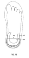
Referring to FIG. 1 , for purposes of reference, article 100 may be divided into forefoot portion 10, midfoot portion 12 and heel portion 14. Forefoot portion 10 may be generally associated with the toes and joints connecting the metatarsals with the phalanges. Midfoot portion 12 may be generally associated with the arch of a foot. Likewise, heel portion 14 may be generally associated with the heel of a foot, including the calcaneus bone. In addition, article 100 may include lateral side 16 and medial side 18. In particular, lateral side 16 and medial side 18 may be opposing sides of article 100. Furthermore, both lateral side 16 and medial side 18 may extend through forefoot portion 10, midfoot portion 12 and heel portion 14.
It will be understood that forefoot portion 10, midfoot portion 12 and heel portion 14 are only intended for purposes of description and are not intended to demarcate precise regions of article 100. Likewise, lateral side 16 and medial side 18 are intended to represent generally two sides of an article, rather than precisely demarcating article 100 into two halves. In addition, forefoot portion 10, midfoot portion 12 and heel portion 14, as well as lateral side 16 and medial side 18, can also be applied to individual components of an article, such as a sole structure and/or an upper.
For consistency and convenience, directional adjectives are employed throughout this detailed description corresponding to the illustrated embodiments. The term “longitudinal” as used throughout this detailed description and in the claims refers to a direction extending a length of an article. In some cases, the longitudinal direction may extend from a forefoot portion to a heel portion of the article. Also, the term “lateral” as used throughout this detailed description and in the claims refers to a direction extending a width of an article. In other words, the lateral direction may extend between a medial side and a lateral side of an article. Furthermore, the term “vertical” as used throughout this detailed description and in the claims refers to a direction generally perpendicular to a lateral and longitudinal direction. For example, in cases where an article is planted flat on a ground surface, the vertical direction may extend from the ground surface upward. In addition, the term “proximal” refers to a portion of a footwear component that is closer to a portion of a foot when an article of footwear is worn. Likewise, the term “distal” refers to a portion of a footwear component that is further from a portion of a foot when an article of footwear is worn. It will be understood that each of these directional adjectives may be applied to individual components of an article, such as an upper and/or a sole structure. In some cases, each of these directional adjectives may be applied to a heel counter for an article of footwear, as discussed below.
In some embodiments, sole structure 110 may be configured to provide traction for article 100. In addition to providing traction, sole structure 110 may attenuate ground reaction forces when compressed between the foot and the ground during walking, running or other ambulatory activities. The configuration of sole structure 110 may vary significantly in different embodiments to include a variety of conventional or non-conventional structures. In some cases, the configuration of sole structure 110 can be configured according to one or more types of ground surfaces on which sole structure 110 may be used. Examples of ground surfaces include, but are not limited to: natural turf, synthetic turf, dirt, as well as other surfaces.
In some cases, midsole 120 may be attached directly to upper 102. In other cases, midsole 120 may be attached to a sockliner associated with upper 102. In different embodiments, midsole 120 may have different material characteristics to provide various levels of comfort, cushioning and/or shock absorption. Examples of different materials that could be used for midsole 120 include, but are not limited to: foam, rubber, plastic, polymers, as well as any other kinds of materials.
In some cases, an outsole may be provided on sole structure 110 to increase traction with a ground surface. Although the current embodiment does not include a separate outsole, other embodiments may include any kind of outsole. An outsole can include one or more tread elements and/or ground penetrating members such as cleats. In some cases, an outsole can have different material characteristics to provide varying levels of traction with a ground surface. Examples of different materials that could be used for an outsole include, but are not limited to: plastic, rubber, polymers, as well as any other kinds of materials that are both durable and wear-resistant.
An article of footwear can include provisions for supporting the heel of a foot. In some embodiments, an article of footwear can include a heel support member, such as a heel counter. A heel counter may be disposed adjacent to the sides and/or rear of the heel. In some cases, a heel counter helps maintain the foot inside of the article of footwear and can help to reduce over-pronation.
In some embodiments, article of footwear 100 may include heel support member 150, also referred to as simply support member 150. In some cases, heel support member 150 could be a heel counter. In other cases, however, heel support member 150 may be any other kind of support member known in the art for supporting the heel of a foot.
In different embodiments, heel support member 150 can be associated with different components of article 100. For example, in some cases, support member 150 may be associated with upper 102. In other cases, support member 150 may be associated with sole structure 110. In still other cases, support member 150 could be associated with upper 102 and sole structure 110.
In different embodiments, support member 150 could be attached to article 100 using a variety of methods. In some cases, for example, support member 150 could be glued, or otherwise bonded to, portions of upper 102 as well as portions of sole structure 110. In other cases, support member 150 could be stitched to portions of upper 102 and/or sole structure 110. Moreover, support member 150 could be attached to article 100 before or after the assembly of upper 102 and sole structure 110.
Although support member 150 is disposed on an outer surface of upper 102 in the current embodiment, and comprises a distinct and separate component from upper 102, other embodiments could include various other configurations. In another embodiment, support member 150 could be integrated into upper 102. For example, support member 150 could be disposed between two layers that comprise upper 102. In another configuration, support member 150 may be attached to an interior surface of upper 102 so that support member 150 is not visible along the outer surface of article 100.
Generally, the geometry of extended portion 160 can vary. In some cases, each of lateral portion 162, medial portion 164 and/or rearward portion 166 may comprise flap-like portions that are spaced apart by various gaps. Referring to FIG. 3 , lateral portion 162 comprises first end portion 182, intermediate portion 185 and a second end portion 184. In some cases, second end portion 184 is substantially wider than intermediate portion 185. Also, as seen in FIG. 5 , medial portion 164 comprises first end portion 186, intermediate portion 187 and second end portion 188. In some cases, second end portion 188 is substantially wider than intermediate portion 187. Also, as seen in FIGS. 3 and 4 , rearward portion 166 comprises first end portion 192, intermediate portion 193 and second end portion 194, which is substantially wider than intermediate portion 193. These widened end portions may provide additional support near the ankle of the foot.
Referring again to FIGS. 3 through 7 , in one embodiment, lateral portion 162 and rearward portion 166 may be spaced apart by first gap 170. Also, in one embodiment, medial portion 164 and rearward portion 166 may be spaced apart by second gap 172. Moreover, second end portion 184 of lateral portion 162 may be disposed closer to rearward portion 166 than first end portion 182. Likewise, second end portion 188 of medial portion 164 may be disposed closer to rearward portion 166 than first end portion 186. In other words, both lateral portion 162 and medial portion 164 generally extend partially in a rearward direction. In addition, in some cases, rearward portion 166 extends in a generally vertical, or proximal, direction.
The current embodiments are only intended to illustrate an exemplary geometry for extended portion 160, including lateral portion 162, medial portion 164 and rearward portion 166. In other embodiments, the geometry of each portion could be varied. Moreover, in other embodiments, extended portion 160 could be divided into more than three portions that are separated by at least three gaps. In still other embodiments, extended portion 160 could be comprised of one portion. In still other embodiments, extended portion 160 could be divided into two portions that are separated by a single gap. For example, in one embodiment, a support member could include a rearward portion and a lateral portion, but not medial portion. As another example, in one embodiment a support member could include a rearward portion and a medial portion, but not a lateral portion. In still another embodiment, a support member could include a lateral portion and a medial portion, but not a rearward portion.
This exemplary configuration for extended portion 160 allows for lateral portion 162, medial portion 164 and rearward portion 166 to act as flap-like supporting portions that bend with respect to base portion 152. This arrangement allows extended portion 160 to expand and/or contract around the heel of a foot.
Fastening member 200 could be any provision used for fastening one or more portions of support member 150 around the heel of a foot. In some cases, fastening member 200 could comprise a strip, strap, string, cord or other fastening member having a distinct first end and a second end. In other cases, fastening member 200 could comprise a ring, band or loop-like fastening member. Furthermore, the elasticity properties of fastening member 200 could vary in different embodiments. In some cases, fastening member 200 could have a low elasticity associated with various types of plastic, leather and/or woven straps. In other cases, fastening member 200 could have a high elasticity associated with various types of extendable straps, elastic bands (such as rubber bands) as well as other types of elastic fastening members known in the art. In one embodiment, fastening member 200 comprises a substantially elastic ring.
Referring now to FIGS. 3 through 5 , support member 150 can include provisions for receiving fastening member 200. Support member 150 can include fastener receiving portions 220. Fastener receiving portions 220 include first fastener receiving portion 222 and second fastener receiving potion 224. In particular, first fastener receiving portion 222 is associated with second end portion 184 of lateral portion 162. Likewise, second fastener receiving portion 224 is associated with second end portion 188 of medial portion 164. Although first fastener receiving portion 222 and second fastener receiving portion 224 are disposed on end portions of lateral portion 162 and medial portion 164, respectively, in other embodiments each fastener receiving portion could be disposed on any other portions of lateral portion 162 and/or medial portion 164.
In different embodiments, the geometry of a fastener receiving portion could vary. In some cases, first fastener receiving portion 222 may have a hook-like geometry that is configured to hold fastening member 200 in place. In one embodiment, first fastener receiving portion 222 includes connecting portion 230 and engaging portion 232. Connecting portion 230 is a relatively narrow portion that extends outwardly from surface 240 of lateral portion 162 and secures engaging portion 232. Engaging portion 232 may be spaced apart from surface 240 of lateral portion 162 so that fastening member 200 can fit between engaging portion 232 and lateral portion 162.
Engaging portion 232 extends in an approximately perpendicular direction from connecting portion 230. In some cases, for example, engaging portion 232 and connecting portion 230 are configured in a T-like shape. Moreover, first fastener receiving portion 222 may be oriented so that connecting portion 230 is disposed more rearwardly along lateral portion 162 than engaging portion 232. Using this arrangement, fastening member 200 may be pulled in tension against first fastener receiving portion 222 and engaging portion 232 may act to prevent fastening member 200 from sliding off of first fastener receiving portion 222.
The geometry for first fastener receiving portion 222 shown here is only intended to be exemplary and in other embodiments, other geometries are also possible. It will be understood that second fastener receiving portion 224 could be provided with a substantially similar geometry to first fastener receiving portion 222. For example, second fastener receiving portion 224 may include connecting portion 258 and engaging portion 259 that are configured in a similar arrangement to connecting portion 230 and engaging portion 232. In other embodiments, however, second fastener receiving portion 224 could have any other geometry. For example, in some cases, second fastener receiving portion 224 could be configured as a closed loop that fixes fastening member 200 in place in a semi-permanent manner.
In some cases, first fastener receiving portion 222 and second fastener receiving portion 224 may be further associated with first raised portion 252 and second raised portion 254, respectively. In some cases, first raised portion 252 and second raised portion 254 may be t-shaped portions that are disposed adjacent to the engaging portions of first fastener receiving portion 222 and second fastener receiving portion 224. In some cases, first raised portion 252 and second raised portion 254 could facilitate aligning fastening member 200 with fastener receiving portions in some embodiments.
In some embodiments, rearward portion 166 may include third fastener receiving portion 226. In some cases, third fastener receiving portion 226 comprises a raised portion that extends outwardly from outer surface 260 of rearward portion 166. In addition, third fastener receiving portion 226 includes openings 264 for receiving fastening member 200 through opposing sides of third fastener receiving portion 226. As seen in FIG. 6 , in some cases, third fastener receiving portion 226 may be substantially hollow and open along inner surface 262 of rearward portion 166.
Using this configuration discussed above, fastening member 200 may be secured through third fastener receiving portion 226 as well as at first fastener receiving portion 222 and second fastener receiving portion 224. In the current embodiment, for example, first portion 202 of fastening member 200 is engaged with first fastener receiving portion 222. In particular, first portion 202 is held in place by engaging portion 232. Also, second portion 204 of fastening member 200 is engaged with second fastener receiving portion 224. In particular, second portion 204 is held in place by engaging portion 259.
Referring now to FIG. 8 , extended portion 160 generally wraps around heel portion 14 of upper 102. In particular, lateral portion 162, medial portion 164 and rearward portion 166 may generally wrap around lateral side 16, medial side 18 and rearward portion 166, respectively. Additionally, portions of base portion 152 may be disposed beneath upper 102 at heel portion 14. This configuration may provide stability and support for a heel disposed inside upper 102.
In the unfastened position shown in FIG. 8 , each of lateral portion 162, medial portion 164 and rearward portion 166 may rest against upper 102.Moreover, in this case, second end portion 184 of lateral portion 162 is spaced apart from rearward portion 166 by spacing 51. Similarly, second end portion 188 of medial portion 164 is spaced apart from rearward portion 166 by spacing 52.
Referring now to FIG. 9 , foot 900 has been inserted into article 100. As foot 900 is inserted, extended portion 160 flexes to accommodate the width of heel 902 of foot 900. In particular, lateral portion 162 and medial portion 164 are flexed away from rearward portion 166. In this stretched position, second end portion 184 of lateral portion 162 is spaced apart from rearward portion 166 by spacing 53 that is substantially larger than the original spacing 51 shown in FIG. 8 . Likewise, second end portion 188 of medial portion 164 is spaced apart from rearward portion 166 by spacing 54 that is substantially larger than the original spacing 52 shown in FIG. 8 . In other words, the size of support member 150 may generally change to accommodate the width of a user's foot.
Initially, before support member 150 is tightened, fastening member 200 may only be fastened at second fastener receiving portion 224, but not first fastener receiving portion 222. Referring to FIG. 10 , in order to tighten support member 150 around heel 902, a user may pull fastening member 200 over first fastener receiving portion 222, so that fastening member 200 is pulled taut from medial portion 164 to lateral portion 162 and across rearward portion 166. As fastening member 200 is tightened, lateral portion 162, medial portion 164 and rearward portion 166 are pulled inwardly to provide a better fit and increased support for heel 902. This can help retain heel 902 in article 100 and can help reduce the occurrence of over-pronation.
In some cases, to facilitate ease of removing foot 900 from article 100, fastening member 200 can be disengaged from either first fastener receiving portion 222 or second fastener receiving portion 224. In some cases, fastening member 200 may be disengaged from both first fastener receiving portion 222 and second fastener receiving portion 224. In the case where fastening member 200 is disengaged from both receiving portions, fastening member 200 may still be secured to support member 150 through its engagement within third fastener receiving portion 226.
In some embodiments, fastening member 200 could be permanently attached to either lateral portion 162 and/or medial portion 164. In cases where fastening member 200 is permanently attached to both lateral portion 162 and medial portion 164, fastening member 200 may expand as a heel is inserted into upper 102. In such cases, fastening member 200 need not be engaged and disengaged to fasten support member 150 around the heel.
The configurations discussed above provide a support member that may serve as a heel counter in an article of footwear. Moreover, the support member is configured to accommodate heels of different sizes, including different widths. This allows a manufacturer to utilize a single heel counter for a variety of different heel widths, rather than making a single heel counter for each heel width. Furthermore, this design accommodates intermediate heel widths that would otherwise not be accommodated, since the support member can adjust to width or size within a given range of sizes. [insert size language—see sockliner case]
While various embodiments have been described, the description is intended to be exemplary, rather than limiting and it will be apparent to those of ordinary skill in the art that many more embodiments and implementations are possible that are within the scope of the embodiments. Accordingly, the embodiments are not to be restricted except in light of the attached claims and their equivalents. Also, various modifications and changes may be made within the scope of the attached claims.
Claims (20)
1. A heel closure apparatus for an article of footwear, comprising:
a heel cup comprising three upwardly extending lobes, including a medial lobe, a lateral lobe, and a central lobe;
a fastener receiving portion disposed at a distal end of the central lobe, the fastener receiving portion comprising a fastener receiving body and defining at least one guide channel extending through the fastener receiving body from a medial side of the fastener receiving portion to a lateral side of the fastener receiving portion;
a medial hook disposed at a distal end of the medial lobe;
a lateral hook disposed at a distal end of the lateral lobe; and
a continuous loop of an elastic cord extending through the at least one guide channel, wherein:
a medial portion of the continuous loop extends outwardly from the at least one guide channel and toward the medial lobe,
a lateral portion of the continuous loop extends outwardly from the at least one guide channel and toward the lateral lobe, and
at least one of the medial portion or the lateral portion of the continuous loop is designed to elastically stretch outwardly from the at least one guide channel and toward a corresponding one of the medial hook or the lateral hook to enable the medial portion or the lateral portion to be captured and retained by the corresponding one of the medial hook or the lateral hook; and
a hook guard disposed proximate and spaced apart from a corresponding one of the medial hook or the lateral hook, wherein the hook guard is t-shaped with a first ramp portion and a cross-bar.
2. The heel closure apparatus of claim 1 , wherein the medial hook and the lateral hook are mirror images of each other.
3. The heel closure apparatus of claim 1 , wherein each of the medial hook and the lateral hook extends away from an exterior surface of a respective one of the medial lobe and the lateral lobe so that an engaging surface of each of the medial hook and the lateral hook faces away from the fastener receiving portion.
4. The heel closure apparatus of claim 1 , wherein at least one of the medial hook and the lateral hook includes a broadened flange proximate an anterior edge of at least one of the medial hook or the lateral hook, and wherein one or more portions of the broadened flange overlap a portion of the continuous loop when the continuous loop is engaged with the at least one of the medial hook and the lateral hook.
5. The heel closure apparatus of claim 1 , wherein at least one of the medial hook or the lateral hook includes a second ramp portion that connects an anterior edge of the corresponding one of the medial hook or the lateral hook to an outward-facing surface of the corresponding one of the medial lobe or the lateral lobe, wherein a ramp height of the second ramp portion of at least one of the medial hook or the lateral hook is greatest proximate the anterior edge of the corresponding one of the medial hook or the lateral hook.
6. The heel closure apparatus of claim 5 , wherein the second ramp portion of at least one of the medial hook or the lateral hook extends towards a gap disposed between a corresponding one of the medial lobe or the lateral lobe and the central lobe.
7. The heel closure apparatus of claim 6 , wherein the ramp height of the second ramp portion of the at least one of the medial hook or the lateral hook is lowest proximate the gap.
8. The heel closure apparatus of claim 1 , wherein the elastic cord is configured to be placed under tension when the medial portion is engaged with the medial hook and the lateral portion is engaged with the lateral hook.
9. The heel closure apparatus of claim 1 , wherein the fastener receiving portion is disposed on an outward-facing surface of the central lobe.
10. The heel closure apparatus of claim 1 wherein the hook guard is a raised portion.
11. The heel closure apparatus of claim 10 , wherein the hook guard is spaced apart from the corresponding one of the medial hook or the lateral hook by a distance that is equal to or greater than a cross-sectional diameter of the elastic cord.
12. A heel closure apparatus for an article of footwear, comprising:
a heel cup comprising three upwardly extending lobes, including a medial lobe, a lateral lobe, and a central lobe;
a fastener disposed at a distal end of the central lobe, the fastener comprising at least one guide channel extending therethrough from a medial side of the fastener to a lateral side of the fastener;
a medial hook disposed at a distal end of the medial lobe;
a lateral hook disposed at a distal end of the lateral lobe; and
a continuous loop of an elastic cord extending through the at least one guide channel, wherein:
a medial portion of the continuous loop extends outwardly from the at least one guide channel and toward the medial lobe,
a lateral portion of the continuous loop extends outwardly from the at least one guide channel and toward the lateral lobe, and
at least one of the medial portion or the lateral portion of the continuous loop is configured to elastically stretch outwardly from the at least one guide channel and toward a corresponding one of the medial hook or the lateral hook to enable the medial portion or the lateral portion to be captured and retained by the corresponding one of the medial hook or the lateral hook;
a hook guard disposed proximate and spaced apart from an engaging surface of the corresponding one of the medial hook or the lateral hook, wherein the hook guard is a raised portion configured to facilitate aligning the elastic cord with the engaging surface of the medial hook; and
wherein the hook guard is t-shaped with a ramp and a cross-bar, and wherein the cross-bar is disposed proximate the corresponding one of the medial hook or the lateral hook and the ramp slopes away from the cross-bar.
13. The heel closure apparatus of claim 1 , wherein the at least one guide channel includes a passage with a minimum cross-sectional diameter that is equal to or greater than a cross-sectional diameter of the elastic cord.
14. The heel closure apparatus of claim 1 , wherein the at least one guide channel includes one or more passages so that the at least one guide channel is configured to receive multiple portions of the elastic cord.
15. The heel closure apparatus of claim 12 , wherein the medial hook and the lateral hook are mirror images of each other.
16. The heel closure apparatus of claim 12 , wherein each of the medial hook and the lateral hook extends away from an exterior surface of a respective one of the medial lobe and the lateral lobe so that an engaging surface of each of the medial hook and the lateral hook faces away from the fastener receiving portion.
17. The heel closure apparatus of claim 12 , wherein at least one of the medial hook and the lateral hook includes a broadened flange proximate an anterior edge of at least one the medial hook or the lateral hook, and wherein one or more portions of the broadened flange overlap a portion of the continuous loop when the continuous loop is engaged with the at least one of the medial hook and the lateral hook.
18. The heel closure apparatus of claim 12 , wherein at least one of the medial hook or the lateral hook includes a ramp that connects an anterior edge of the corresponding one of the medial hook or the lateral hook to an outward-facing surface of the corresponding one of the medial lobe or lateral lobe, wherein a ramp height of the ramp of at least one of the medial hook or the lateral hook is greatest proximate the anterior edge of the corresponding one of the medial hook or the lateral hook.
19. The heel closure apparatus of claim 18 , wherein the ramp of at least one of the medial hook or the lateral hook extends towards a gap disposed between the corresponding one of the medial lobe or lateral lobe and the central lobe.
20. The heel closure apparatus of claim 19 , wherein the ramp height of the ramp of the at least one of the medial hook or the lateral hook is least proximate the gap.
Priority Applications (4)
| Application Number | Priority Date | Filing Date | Title |
|---|---|---|---|
| US14/803,602 US9795187B2 (en) | 2011-02-09 | 2015-07-20 | Adjustable heel support member for article of footwear |
| US15/719,804 US10568386B2 (en) | 2011-02-09 | 2017-09-29 | Adjustable heel support member for article of footwear |
| US16/745,681 US11253027B2 (en) | 2011-02-09 | 2020-01-17 | Adjustable heel support member for article of footwear |
| US17/577,207 US11918075B2 (en) | 2011-02-09 | 2022-01-17 | Adjustable heel support member for article of footwear |
Applications Claiming Priority (2)
| Application Number | Priority Date | Filing Date | Title |
|---|---|---|---|
| US13/023,676 US9095188B2 (en) | 2011-02-09 | 2011-02-09 | Adjustable heel support member for article of footwear |
| US14/803,602 US9795187B2 (en) | 2011-02-09 | 2015-07-20 | Adjustable heel support member for article of footwear |
Related Parent Applications (1)
| Application Number | Title | Priority Date | Filing Date |
|---|---|---|---|
| US13/023,676 Continuation US9095188B2 (en) | 2011-02-09 | 2011-02-09 | Adjustable heel support member for article of footwear |
Related Child Applications (1)
| Application Number | Title | Priority Date | Filing Date |
|---|---|---|---|
| US15/719,804 Continuation US10568386B2 (en) | 2011-02-09 | 2017-09-29 | Adjustable heel support member for article of footwear |
Publications (2)
| Publication Number | Publication Date |
|---|---|
| US20160015129A1 US20160015129A1 (en) | 2016-01-21 |
| US9795187B2 true US9795187B2 (en) | 2017-10-24 |
Family
ID=45774277
Family Applications (5)
| Application Number | Title | Priority Date | Filing Date |
|---|---|---|---|
| US13/023,676 Active 2032-05-24 US9095188B2 (en) | 2011-02-09 | 2011-02-09 | Adjustable heel support member for article of footwear |
| US14/803,602 Active 2031-02-20 US9795187B2 (en) | 2011-02-09 | 2015-07-20 | Adjustable heel support member for article of footwear |
| US15/719,804 Active 2031-04-10 US10568386B2 (en) | 2011-02-09 | 2017-09-29 | Adjustable heel support member for article of footwear |
| US16/745,681 Active 2031-05-19 US11253027B2 (en) | 2011-02-09 | 2020-01-17 | Adjustable heel support member for article of footwear |
| US17/577,207 Active 2031-02-28 US11918075B2 (en) | 2011-02-09 | 2022-01-17 | Adjustable heel support member for article of footwear |
Family Applications Before (1)
| Application Number | Title | Priority Date | Filing Date |
|---|---|---|---|
| US13/023,676 Active 2032-05-24 US9095188B2 (en) | 2011-02-09 | 2011-02-09 | Adjustable heel support member for article of footwear |
Family Applications After (3)
| Application Number | Title | Priority Date | Filing Date |
|---|---|---|---|
| US15/719,804 Active 2031-04-10 US10568386B2 (en) | 2011-02-09 | 2017-09-29 | Adjustable heel support member for article of footwear |
| US16/745,681 Active 2031-05-19 US11253027B2 (en) | 2011-02-09 | 2020-01-17 | Adjustable heel support member for article of footwear |
| US17/577,207 Active 2031-02-28 US11918075B2 (en) | 2011-02-09 | 2022-01-17 | Adjustable heel support member for article of footwear |
Country Status (2)
| Country | Link |
|---|---|
| US (5) | US9095188B2 (en) |
| WO (1) | WO2012107822A2 (en) |
Cited By (2)
| Publication number | Priority date | Publication date | Assignee | Title |
|---|---|---|---|---|
| US20140259766A1 (en) * | 2013-03-15 | 2014-09-18 | Laurence James | Shoe Construction |
| US10602797B2 (en) | 2015-07-27 | 2020-03-31 | Chris Lintaman | Length-adjustable shoe |
Families Citing this family (44)
| Publication number | Priority date | Publication date | Assignee | Title |
|---|---|---|---|---|
| US9655406B2 (en) * | 2014-08-01 | 2017-05-23 | Nike, Inc. | Article of footwear having an adjustable heel system |
| US10863793B2 (en) | 2015-05-29 | 2020-12-15 | Nike, Inc. | Footwear system with an article of footwear having an upper with medial and lateral side portions with separately securable distal ends |
| TWI577299B (en) * | 2015-07-27 | 2017-04-11 | Chris Lintaman | Adjustable length of shoes |
| JP6529206B2 (en) * | 2016-07-19 | 2019-06-12 | 株式会社アシックス | shoes |
| CN112586837B (en) * | 2016-10-26 | 2022-08-26 | 耐克创新有限合伙公司 | Heel spring device for shoes |
| US10568382B2 (en) | 2016-10-26 | 2020-02-25 | Nike, Inc. | Upper component for an article of footwear |
| EP4066672A1 (en) | 2016-10-26 | 2022-10-05 | NIKE Innovate C.V. | Hinged footwear sole structure for foot entry and method of manufacturing |
| EP3534744B1 (en) * | 2016-11-01 | 2021-03-24 | Nike Innovate C.V. | Lace guide for an article of footwear |
| USD804800S1 (en) * | 2017-02-10 | 2017-12-12 | Nike, Inc. | Shoe upper |
| US11304479B2 (en) | 2017-02-28 | 2022-04-19 | Nike, Inc. | Footwear with laceless fastening system |
| US10758010B2 (en) | 2017-04-17 | 2020-09-01 | Nike, Inc. | Increased access footwear |
| CN110662445B (en) | 2017-05-23 | 2021-08-17 | 耐克创新有限合伙公司 | Footwear upper with zipper system to join laces |
| EP4056065A1 (en) | 2017-05-23 | 2022-09-14 | NIKE Innovate C.V. | Rear access article of footwear with movable heel portion |
| US10159310B2 (en) | 2017-05-25 | 2018-12-25 | Nike, Inc. | Rear closing upper for an article of footwear with front zipper to rear cord connection |
| CN108041748A (en) * | 2018-01-31 | 2018-05-18 | 贵人鸟股份有限公司 | A kind of sole of customizable heel support |
| US10834998B2 (en) * | 2018-04-13 | 2020-11-17 | Wolverine Outdoors, Inc. | Footwear including a holding cage |
| CN111970940B (en) | 2018-04-13 | 2022-02-01 | 耐克创新有限合伙公司 | Footwear fastening system |
| GB201808830D0 (en) * | 2018-05-30 | 2018-07-11 | Juju Ltd | Wellington boot with heel retaining clip |
| USD854303S1 (en) | 2018-06-14 | 2019-07-23 | Nike, Inc. | Shoe |
| USD840663S1 (en) | 2018-06-14 | 2019-02-19 | Nike, Inc. | Shoe |
| USD853707S1 (en) | 2018-06-14 | 2019-07-16 | Nike, Inc. | Shoe |
| US10455898B1 (en) | 2018-12-21 | 2019-10-29 | Nike, Inc. | Footwear article with tongue reinforcer |
| US10617174B1 (en) | 2018-12-21 | 2020-04-14 | Nike, Inc. | Footwear article with doffing ledge |
| CN115844103A (en) | 2018-12-28 | 2023-03-28 | 耐克创新有限合伙公司 | Easy entry footwear with articulating sole structure |
| US10721994B2 (en) | 2018-12-28 | 2020-07-28 | Nike, Inc. | Heel structure with locating pegs and method of manufacturing an article of footwear |
| US11344077B2 (en) | 2018-12-28 | 2022-05-31 | Nike, Inc. | Footwear article with collar elevator |
| CN113194775B (en) * | 2018-12-28 | 2023-08-29 | 耐克创新有限合伙公司 | Footwear element with locating pegs and method of manufacturing an article of footwear |
| EP3902432B1 (en) | 2018-12-28 | 2024-03-06 | NIKE Innovate C.V. | Footwear with vertically extended heel counter |
| WO2020167445A1 (en) | 2019-02-13 | 2020-08-20 | Nike Innovate C.V. | Footwear heel support device |
| US11122861B2 (en) * | 2019-05-16 | 2021-09-21 | Under Armour, Inc. | Heel counter |
| US11707113B2 (en) | 2019-10-18 | 2023-07-25 | Nike, Inc. | Easy-access article of footwear with cord lock |
| CN114727688A (en) | 2019-11-25 | 2022-07-08 | 耐克创新有限合伙公司 | Tension retention system for wearable articles |
| USD929108S1 (en) * | 2019-11-27 | 2021-08-31 | Nike, Inc. | Shoe |
| USD923316S1 (en) * | 2019-11-27 | 2021-06-29 | Nike, Inc. | Shoe |
| EP4087436B1 (en) * | 2020-01-07 | 2024-03-06 | Nike Innovate C.V. | Articles of footwear with adjustable dimensions |
| USD923930S1 (en) * | 2020-03-20 | 2021-07-06 | Nike, Inc. | Shoe |
| USD1007133S1 (en) | 2021-02-05 | 2023-12-12 | Kane Footwear LLC | Shoe |
| USD1006425S1 (en) | 2021-02-05 | 2023-12-05 | Kane Footwear LLC | Shoe |
| USD1021341S1 (en) | 2021-02-05 | 2024-04-09 | Kane Footwear LLC | Shoe |
| USD1006423S1 (en) * | 2021-02-05 | 2023-12-05 | Kane Footwear LLC | Shoe |
| USD1022412S1 (en) | 2021-02-05 | 2024-04-16 | Kane Footwear LLC | Shoe |
| USD1002154S1 (en) | 2021-02-05 | 2023-10-24 | Kane Footwear LLC | Shoe |
| US20230148708A1 (en) * | 2021-11-12 | 2023-05-18 | Nike, Inc. | Articles of footwear and other foot-receiving devices having dynamically adjustable heel portions |
| US11910867B2 (en) | 2022-03-28 | 2024-02-27 | Nike, Inc. | Article of footwear with heel entry device |
Citations (42)
| Publication number | Priority date | Publication date | Assignee | Title |
|---|---|---|---|---|
| US178387A (en) | 1876-06-06 | Improvement in counter-stiffeners for boots and shoes | ||
| US256030A (en) | 1882-04-04 | Metallic counter-support for boots and shoes | ||
| US912579A (en) | 1908-05-09 | 1909-02-16 | Frederick W Krech | Heel-pad. |
| US1091704A (en) | 1911-05-29 | 1914-03-31 | George L Preble | Counter-stiffener. |
| GB163641A (en) | 1920-11-01 | 1921-05-26 | William Sidney Howard Doody | Improvements in sandals or slippers |
| US2935798A (en) | 1957-06-21 | 1960-05-10 | Piberhofer Karl | Ski boot |
| US2942359A (en) | 1959-05-20 | 1960-06-28 | Tyer Rubber Company | Article of footwear with integral ankle and heel support |
| US3192651A (en) | 1963-12-16 | 1965-07-06 | Robert D Smith | Shoe having a rear opening |
| US3425075A (en) | 1965-06-24 | 1969-02-04 | Alan E Murray | Method of making leather footwear |
| US3613274A (en) | 1969-11-06 | 1971-10-19 | Sally M Willey | Heel stiffeners |
| US4308673A (en) | 1978-06-29 | 1982-01-05 | Deutsche Gold-Und Silber-Scheideanstalt Vormals Roessler | Stiffening and likewise non-slip material for the heel region of shoes containing this material and process for stiffening the heel region of shoes |
| FR2534116A1 (en) | 1982-10-07 | 1984-04-13 | Salomon & Fils F | Flat sports shoe for langlauf skiing |
| WO1988008678A1 (en) | 1987-05-06 | 1988-11-17 | Adidas Sportschuhfabriken Adi Dassler Stiftung & C | Sports shoe with elastic heel counter |
| US4969277A (en) | 1986-11-28 | 1990-11-13 | Williams Paul H | Adjustable shoe |
| US4970763A (en) * | 1989-08-10 | 1990-11-20 | Luck Nwoko | Hook-type speed fastening device with optional integrated, adjustable width, adjustable tension, eyelet capacity |
| US5152084A (en) | 1990-12-20 | 1992-10-06 | Salomon S.A. | Rear entry ski boot with a closing strap cover |
| US5152082A (en) | 1991-12-16 | 1992-10-06 | Culpepper Thomas C | Shoe and ankle support therefor |
| US5291671A (en) | 1991-06-10 | 1994-03-08 | Arkos S.R.L. | Foot securing device particularly for trekking boots |
| US5408761A (en) | 1992-04-09 | 1995-04-25 | A. D. One Sports, Inc. | Sport shoe and support system |
| USD386895S (en) | 1996-06-05 | 1997-12-02 | Nike, Inc. | Element of a shoe |
| US5699629A (en) | 1996-08-08 | 1997-12-23 | Munschy; Dorothy G. | Adjustable footwear |
| US5946825A (en) | 1997-01-31 | 1999-09-07 | Nine West Group, Inc. | Footwear having slow recovery liner |
| US6000148A (en) | 1997-06-27 | 1999-12-14 | Salomon S.A. | Multi-layered sole coupled to a reinforcement of the upper of the boot |
| US6079128A (en) | 1993-11-30 | 2000-06-27 | Bauer Nike Hockey Inc. | Skate boot construction with integral plastic insert |
| US6189239B1 (en) | 1997-10-31 | 2001-02-20 | D. Gasparovic | Articulated footwear having a flexure member |
| US6295743B1 (en) | 1998-04-13 | 2001-10-02 | Marc D. Brooks | Boot with heel-back fastening mechanism |
| US6401366B2 (en) | 1999-04-16 | 2002-06-11 | Nike, Inc. | Athletic shoe with stabilizing frame |
| US6568103B2 (en) * | 2000-12-28 | 2003-05-27 | Bauer Nike Hockey Inc. | Speed lacing device |
| US6622401B2 (en) | 2001-07-18 | 2003-09-23 | Carroll, Iii Lester Erwin | Modified oxford shoe providing vertical and horizontal heel pressure diminishment including an optional means of adjusting pronation |
| WO2004043184A1 (en) | 2002-11-12 | 2004-05-27 | Blue Marble Gear, Llc | Component footwear system |
| US20050081404A1 (en) | 2003-10-21 | 2005-04-21 | Nike, Inc. | Engaging element useful for securing objects, such as footwear and other foot-receiving devices |
| US20050267775A1 (en) | 2004-06-01 | 2005-12-01 | Willis Charles C | Footwear design and marketing method |
| US20060010718A1 (en) | 2004-07-15 | 2006-01-19 | Auger Perry W | Article footwear with removable heel pad |
| US7059069B2 (en) | 2002-10-28 | 2006-06-13 | Francis Raluy | Shoe comprising automatic closing system |
| USD535812S1 (en) | 2005-06-02 | 2007-01-30 | Wolverine World Wide, Inc. | Footwear upper |
| US20080148600A1 (en) | 2006-12-20 | 2008-06-26 | Aveni Michael A | Article of Footwear with Expandable Heel Portion |
| US20080301974A1 (en) | 2005-02-03 | 2008-12-11 | 311 Industries, Corp. | Overshoe |
| EP2204102A1 (en) | 2008-12-31 | 2010-07-07 | Alpina | Heel hold regulation device |
| USD619348S1 (en) | 2009-12-15 | 2010-07-13 | Aetrex Worldwide, Inc. | Athletic shoe with heel strap |
| US7757412B2 (en) | 2005-09-28 | 2010-07-20 | Salomon S.A.S. | Footwear with improved heel support |
| US20100199522A1 (en) | 2006-08-10 | 2010-08-12 | Bo Yeoun Hwang | Shoe with elasticity |
| US7793438B1 (en) | 2007-01-26 | 2010-09-14 | Reebok International Ltd. | Rear entry footwear |
Family Cites Families (2)
| Publication number | Priority date | Publication date | Assignee | Title |
|---|---|---|---|---|
| US4510701A (en) * | 1983-06-15 | 1985-04-16 | H. H. Brown Shoe Co., Inc. | Athletic shoe and counter |
| US8020317B1 (en) * | 2007-04-05 | 2011-09-20 | Nike, Inc. | Footwear with integrated biased heel fit device |
-
2011
- 2011-02-09 US US13/023,676 patent/US9095188B2/en active Active
-
2012
- 2012-02-07 WO PCT/IB2012/000212 patent/WO2012107822A2/en active Application Filing
-
2015
- 2015-07-20 US US14/803,602 patent/US9795187B2/en active Active
-
2017
- 2017-09-29 US US15/719,804 patent/US10568386B2/en active Active
-
2020
- 2020-01-17 US US16/745,681 patent/US11253027B2/en active Active
-
2022
- 2022-01-17 US US17/577,207 patent/US11918075B2/en active Active
Patent Citations (43)
| Publication number | Priority date | Publication date | Assignee | Title |
|---|---|---|---|---|
| US178387A (en) | 1876-06-06 | Improvement in counter-stiffeners for boots and shoes | ||
| US256030A (en) | 1882-04-04 | Metallic counter-support for boots and shoes | ||
| US912579A (en) | 1908-05-09 | 1909-02-16 | Frederick W Krech | Heel-pad. |
| US1091704A (en) | 1911-05-29 | 1914-03-31 | George L Preble | Counter-stiffener. |
| GB163641A (en) | 1920-11-01 | 1921-05-26 | William Sidney Howard Doody | Improvements in sandals or slippers |
| US2935798A (en) | 1957-06-21 | 1960-05-10 | Piberhofer Karl | Ski boot |
| US2942359A (en) | 1959-05-20 | 1960-06-28 | Tyer Rubber Company | Article of footwear with integral ankle and heel support |
| US3192651A (en) | 1963-12-16 | 1965-07-06 | Robert D Smith | Shoe having a rear opening |
| US3425075A (en) | 1965-06-24 | 1969-02-04 | Alan E Murray | Method of making leather footwear |
| US3613274A (en) | 1969-11-06 | 1971-10-19 | Sally M Willey | Heel stiffeners |
| US4308673A (en) | 1978-06-29 | 1982-01-05 | Deutsche Gold-Und Silber-Scheideanstalt Vormals Roessler | Stiffening and likewise non-slip material for the heel region of shoes containing this material and process for stiffening the heel region of shoes |
| FR2534116A1 (en) | 1982-10-07 | 1984-04-13 | Salomon & Fils F | Flat sports shoe for langlauf skiing |
| US4969277A (en) | 1986-11-28 | 1990-11-13 | Williams Paul H | Adjustable shoe |
| WO1988008678A1 (en) | 1987-05-06 | 1988-11-17 | Adidas Sportschuhfabriken Adi Dassler Stiftung & C | Sports shoe with elastic heel counter |
| US4970763A (en) * | 1989-08-10 | 1990-11-20 | Luck Nwoko | Hook-type speed fastening device with optional integrated, adjustable width, adjustable tension, eyelet capacity |
| US5152084A (en) | 1990-12-20 | 1992-10-06 | Salomon S.A. | Rear entry ski boot with a closing strap cover |
| US5291671A (en) | 1991-06-10 | 1994-03-08 | Arkos S.R.L. | Foot securing device particularly for trekking boots |
| US5152082A (en) | 1991-12-16 | 1992-10-06 | Culpepper Thomas C | Shoe and ankle support therefor |
| US5408761A (en) | 1992-04-09 | 1995-04-25 | A. D. One Sports, Inc. | Sport shoe and support system |
| US6079128A (en) | 1993-11-30 | 2000-06-27 | Bauer Nike Hockey Inc. | Skate boot construction with integral plastic insert |
| USD386895S (en) | 1996-06-05 | 1997-12-02 | Nike, Inc. | Element of a shoe |
| US5699629A (en) | 1996-08-08 | 1997-12-23 | Munschy; Dorothy G. | Adjustable footwear |
| US5946825A (en) | 1997-01-31 | 1999-09-07 | Nine West Group, Inc. | Footwear having slow recovery liner |
| US6000148A (en) | 1997-06-27 | 1999-12-14 | Salomon S.A. | Multi-layered sole coupled to a reinforcement of the upper of the boot |
| US6189239B1 (en) | 1997-10-31 | 2001-02-20 | D. Gasparovic | Articulated footwear having a flexure member |
| US6295743B1 (en) | 1998-04-13 | 2001-10-02 | Marc D. Brooks | Boot with heel-back fastening mechanism |
| US6401366B2 (en) | 1999-04-16 | 2002-06-11 | Nike, Inc. | Athletic shoe with stabilizing frame |
| US6568103B2 (en) * | 2000-12-28 | 2003-05-27 | Bauer Nike Hockey Inc. | Speed lacing device |
| US6622401B2 (en) | 2001-07-18 | 2003-09-23 | Carroll, Iii Lester Erwin | Modified oxford shoe providing vertical and horizontal heel pressure diminishment including an optional means of adjusting pronation |
| US7059069B2 (en) | 2002-10-28 | 2006-06-13 | Francis Raluy | Shoe comprising automatic closing system |
| WO2004043184A1 (en) | 2002-11-12 | 2004-05-27 | Blue Marble Gear, Llc | Component footwear system |
| US20050081404A1 (en) | 2003-10-21 | 2005-04-21 | Nike, Inc. | Engaging element useful for securing objects, such as footwear and other foot-receiving devices |
| US20050267775A1 (en) | 2004-06-01 | 2005-12-01 | Willis Charles C | Footwear design and marketing method |
| US20060010718A1 (en) | 2004-07-15 | 2006-01-19 | Auger Perry W | Article footwear with removable heel pad |
| US20080301974A1 (en) | 2005-02-03 | 2008-12-11 | 311 Industries, Corp. | Overshoe |
| USD535812S1 (en) | 2005-06-02 | 2007-01-30 | Wolverine World Wide, Inc. | Footwear upper |
| US7757412B2 (en) | 2005-09-28 | 2010-07-20 | Salomon S.A.S. | Footwear with improved heel support |
| US20100199522A1 (en) | 2006-08-10 | 2010-08-12 | Bo Yeoun Hwang | Shoe with elasticity |
| US20080148600A1 (en) | 2006-12-20 | 2008-06-26 | Aveni Michael A | Article of Footwear with Expandable Heel Portion |
| US7743531B2 (en) | 2006-12-20 | 2010-06-29 | Nike, Inc. | Article of footwear with expandable heel portion |
| US7793438B1 (en) | 2007-01-26 | 2010-09-14 | Reebok International Ltd. | Rear entry footwear |
| EP2204102A1 (en) | 2008-12-31 | 2010-07-07 | Alpina | Heel hold regulation device |
| USD619348S1 (en) | 2009-12-15 | 2010-07-13 | Aetrex Worldwide, Inc. | Athletic shoe with heel strap |
Non-Patent Citations (3)
| Title |
|---|
| International Preliminary Report on Patentability and Written Opinion for Application No. PCT/IB2012/000212, mailed Aug. 22, 2013. |
| International Search Report and Written Opinion for Application No. PCT/IB2012/000212, mailed Sep. 25, 2012. |
| Partial International Search Report for Application No. PCT/IB2012/000212, mailed Jul. 10, 2012. |
Cited By (6)
| Publication number | Priority date | Publication date | Assignee | Title |
|---|---|---|---|---|
| US20140259766A1 (en) * | 2013-03-15 | 2014-09-18 | Laurence James | Shoe Construction |
| US10238168B2 (en) * | 2013-03-15 | 2019-03-26 | Laurence James | Shoe construction |
| US11291267B2 (en) * | 2013-03-15 | 2022-04-05 | Laurence James | Shoe construction |
| US20220175083A1 (en) * | 2013-03-15 | 2022-06-09 | Laurence James | Adjustable closure system for an article |
| US10602797B2 (en) | 2015-07-27 | 2020-03-31 | Chris Lintaman | Length-adjustable shoe |
| DE112015006734B4 (en) | 2015-07-27 | 2022-10-27 | Chris Lintaman | Length-adjustable shoe |
Also Published As
| Publication number | Publication date |
|---|---|
| US20180020773A1 (en) | 2018-01-25 |
| US11918075B2 (en) | 2024-03-05 |
| US20160015129A1 (en) | 2016-01-21 |
| US11253027B2 (en) | 2022-02-22 |
| US20220132990A1 (en) | 2022-05-05 |
| US10568386B2 (en) | 2020-02-25 |
| US20200146398A1 (en) | 2020-05-14 |
| WO2012107822A3 (en) | 2012-11-15 |
| US9095188B2 (en) | 2015-08-04 |
| US20120198721A1 (en) | 2012-08-09 |
| WO2012107822A2 (en) | 2012-08-16 |
Similar Documents
| Publication | Publication Date | Title |
|---|---|---|
| US11918075B2 (en) | Adjustable heel support member for article of footwear | |
| US10405606B2 (en) | Article of footwear with decoupled upper | |
| CN109068792B (en) | Tensioning system for an article of footwear | |
| US9259048B2 (en) | Article of footwear with straps | |
| EP2490565B1 (en) | Easy-to-wear lace up article of footwear | |
| US8677654B2 (en) | Article of footwear with tongue of varying thickness | |
| US20220079293A1 (en) | Lace guide for articles of footwear |
Legal Events
| Date | Code | Title | Description |
|---|---|---|---|
| AS | Assignment |
Owner name: NIKE, INC., OREGON Free format text: ASSIGNMENT OF ASSIGNORS INTEREST;ASSIGNOR:CAVALIERE, SERGIO;REEL/FRAME:042794/0656 Effective date: 20110316 |
|
| STCF | Information on status: patent grant |
Free format text: PATENTED CASE |
|
| MAFP | Maintenance fee payment |
Free format text: PAYMENT OF MAINTENANCE FEE, 4TH YEAR, LARGE ENTITY (ORIGINAL EVENT CODE: M1551); ENTITY STATUS OF PATENT OWNER: LARGE ENTITY Year of fee payment: 4 |