US9795447B2 - Robotic catheter device cartridge - Google Patents
Robotic catheter device cartridge Download PDFInfo
- Publication number
- US9795447B2 US9795447B2 US14/204,231 US201414204231A US9795447B2 US 9795447 B2 US9795447 B2 US 9795447B2 US 201414204231 A US201414204231 A US 201414204231A US 9795447 B2 US9795447 B2 US 9795447B2
- Authority
- US
- United States
- Prior art keywords
- cartridge
- catheter
- manipulation base
- sheath
- finger
- Prior art date
- Legal status (The legal status is an assumption and is not a legal conclusion. Google has not performed a legal analysis and makes no representation as to the accuracy of the status listed.)
- Active, expires
Links
Images


Classifications
-
- A61B19/2203—
-
- A—HUMAN NECESSITIES
- A61—MEDICAL OR VETERINARY SCIENCE; HYGIENE
- A61B—DIAGNOSIS; SURGERY; IDENTIFICATION
- A61B34/00—Computer-aided surgery; Manipulators or robots specially adapted for use in surgery
- A61B34/30—Surgical robots
-
- A—HUMAN NECESSITIES
- A61—MEDICAL OR VETERINARY SCIENCE; HYGIENE
- A61B—DIAGNOSIS; SURGERY; IDENTIFICATION
- A61B34/00—Computer-aided surgery; Manipulators or robots specially adapted for use in surgery
- A61B34/30—Surgical robots
- A61B34/37—Master-slave robots
-
- A—HUMAN NECESSITIES
- A61—MEDICAL OR VETERINARY SCIENCE; HYGIENE
- A61B—DIAGNOSIS; SURGERY; IDENTIFICATION
- A61B34/00—Computer-aided surgery; Manipulators or robots specially adapted for use in surgery
- A61B34/70—Manipulators specially adapted for use in surgery
- A61B34/71—Manipulators operated by drive cable mechanisms
-
- A—HUMAN NECESSITIES
- A61—MEDICAL OR VETERINARY SCIENCE; HYGIENE
- A61B—DIAGNOSIS; SURGERY; IDENTIFICATION
- A61B17/00—Surgical instruments, devices or methods, e.g. tourniquets
- A61B17/34—Trocars; Puncturing needles
- A61B17/3478—Endoscopic needles, e.g. for infusion
-
- A—HUMAN NECESSITIES
- A61—MEDICAL OR VETERINARY SCIENCE; HYGIENE
- A61B—DIAGNOSIS; SURGERY; IDENTIFICATION
- A61B17/00—Surgical instruments, devices or methods, e.g. tourniquets
- A61B17/00234—Surgical instruments, devices or methods, e.g. tourniquets for minimally invasive surgery
- A61B2017/00292—Surgical instruments, devices or methods, e.g. tourniquets for minimally invasive surgery mounted on or guided by flexible, e.g. catheter-like, means
- A61B2017/003—Steerable
-
- A—HUMAN NECESSITIES
- A61—MEDICAL OR VETERINARY SCIENCE; HYGIENE
- A61B—DIAGNOSIS; SURGERY; IDENTIFICATION
- A61B17/00—Surgical instruments, devices or methods, e.g. tourniquets
- A61B2017/00477—Coupling
-
- A—HUMAN NECESSITIES
- A61—MEDICAL OR VETERINARY SCIENCE; HYGIENE
- A61B—DIAGNOSIS; SURGERY; IDENTIFICATION
- A61B17/00—Surgical instruments, devices or methods, e.g. tourniquets
- A61B2017/00831—Material properties
- A61B2017/00876—Material properties magnetic
-
- A—HUMAN NECESSITIES
- A61—MEDICAL OR VETERINARY SCIENCE; HYGIENE
- A61B—DIAGNOSIS; SURGERY; IDENTIFICATION
- A61B34/00—Computer-aided surgery; Manipulators or robots specially adapted for use in surgery
- A61B34/10—Computer-aided planning, simulation or modelling of surgical operations
- A61B2034/101—Computer-aided simulation of surgical operations
- A61B2034/105—Modelling of the patient, e.g. for ligaments or bones
-
- A—HUMAN NECESSITIES
- A61—MEDICAL OR VETERINARY SCIENCE; HYGIENE
- A61B—DIAGNOSIS; SURGERY; IDENTIFICATION
- A61B34/00—Computer-aided surgery; Manipulators or robots specially adapted for use in surgery
- A61B34/30—Surgical robots
- A61B2034/301—Surgical robots for introducing or steering flexible instruments inserted into the body, e.g. catheters or endoscopes
-
- A—HUMAN NECESSITIES
- A61—MEDICAL OR VETERINARY SCIENCE; HYGIENE
- A61B—DIAGNOSIS; SURGERY; IDENTIFICATION
- A61B34/00—Computer-aided surgery; Manipulators or robots specially adapted for use in surgery
- A61B34/70—Manipulators specially adapted for use in surgery
- A61B34/71—Manipulators operated by drive cable mechanisms
- A61B2034/715—Cable tensioning mechanisms for removing slack
-
- A—HUMAN NECESSITIES
- A61—MEDICAL OR VETERINARY SCIENCE; HYGIENE
- A61B—DIAGNOSIS; SURGERY; IDENTIFICATION
- A61B34/00—Computer-aided surgery; Manipulators or robots specially adapted for use in surgery
- A61B34/70—Manipulators specially adapted for use in surgery
- A61B34/74—Manipulators with manual electric input means
- A61B2034/742—Joysticks
-
- A—HUMAN NECESSITIES
- A61—MEDICAL OR VETERINARY SCIENCE; HYGIENE
- A61B—DIAGNOSIS; SURGERY; IDENTIFICATION
- A61B90/00—Instruments, implements or accessories specially adapted for surgery or diagnosis and not covered by any of the groups A61B1/00 - A61B50/00, e.g. for luxation treatment or for protecting wound edges
- A61B90/36—Image-producing devices or illumination devices not otherwise provided for
- A61B90/37—Surgical systems with images on a monitor during operation
- A61B2090/372—Details of monitor hardware
-
- A—HUMAN NECESSITIES
- A61—MEDICAL OR VETERINARY SCIENCE; HYGIENE
- A61M—DEVICES FOR INTRODUCING MEDIA INTO, OR ONTO, THE BODY; DEVICES FOR TRANSDUCING BODY MEDIA OR FOR TAKING MEDIA FROM THE BODY; DEVICES FOR PRODUCING OR ENDING SLEEP OR STUPOR
- A61M25/00—Catheters; Hollow probes
- A61M25/01—Introducing, guiding, advancing, emplacing or holding catheters
- A61M25/0105—Steering means as part of the catheter or advancing means; Markers for positioning
- A61M25/0133—Tip steering devices
- A61M25/0136—Handles therefor
-
- A—HUMAN NECESSITIES
- A61—MEDICAL OR VETERINARY SCIENCE; HYGIENE
- A61M—DEVICES FOR INTRODUCING MEDIA INTO, OR ONTO, THE BODY; DEVICES FOR TRANSDUCING BODY MEDIA OR FOR TAKING MEDIA FROM THE BODY; DEVICES FOR PRODUCING OR ENDING SLEEP OR STUPOR
- A61M25/00—Catheters; Hollow probes
- A61M25/01—Introducing, guiding, advancing, emplacing or holding catheters
- A61M25/0105—Steering means as part of the catheter or advancing means; Markers for positioning
- A61M25/0133—Tip steering devices
- A61M25/0147—Tip steering devices with movable mechanical means, e.g. pull wires
Definitions
- This invention relates to a robotic catheter system and method for automated control of a catheter and related components.
- the instant invention relates to a removable robotic catheter device cartridge usable with a robotic catheter system for manipulating a catheter and related components, for example, for diagnostic, therapeutic, mapping and ablative procedures.
- Electrophysiology catheters are used in a variety of diagnostic and/or therapeutic medical procedures to correct conditions such as atrial arrhythmia, including for example, ectopic atrial tachycardia, atrial fibrillation, and atrial flutter.
- Arrhythmia can create a variety of dangerous conditions including irregular heart rates, loss of synchronous atrioventricular contractions and stasis of blood flow which can lead to a variety of ailments and even death.
- a catheter is manipulated through a patient's vasculature to, for example, a patient's heart, and carries one or more electrodes which may be used for mapping, ablation, diagnosis, or other treatments.
- treatment may include radio frequency (RF) ablation, cryoablation, lasers, chemicals, high-intensity focused ultrasound, etc.
- RF radio frequency
- An ablation catheter imparts such ablative energy to cardiac tissue to create a lesion in the cardiac tissue. This lesion disrupts undesirable electrical pathways and thereby limits or prevents stray electrical signals that lead to arrhythmias.
- RF radio frequency
- the inventors herein have thus recognized a need for a system and method for precise and dynamic automated control of a catheter and its related components, for example, for diagnostic, therapeutic, mapping and ablative procedures, that will minimize and/or eliminate procedural variability due to a user's skill level.
- the inventors herein have also recognized a need for a system and method for performing user-specified procedures at the patient site or from a remote location.
- a system and method for precise and dynamic automated control for example, for diagnostic, therapeutic, mapping and ablative procedures, that will minimize and/or eliminate procedural variability due to a user's skill level, and minimize and/or eliminate radiation exposure from fluoroscopy by moving the staff away from the patient, with the procedures being optionally performed at the patient site or from a remote location.
- a system and method for precise and dynamic automated control of a catheter and its related components may include a robotic catheter device cartridge that eliminates backlash, “slop” and other discontinuities in catheter and sheath control that can make computer control thereof difficult.
- the system and method as discussed herein, may generally include a linear mechanism between the drive means and catheter tip, as opposed to a rotary system which operates on the radius change of a wire for controlling a catheter tip, thus significantly enhancing the overall control function.
- a system and method for precise and dynamic automated control of a catheter and its related components may include a robotic catheter device cartridge including a finger or a slider block generally disposed in a channel and engaged with a steering wire.
- the steering wire may control movement of a component having the steering wire engaged thereto when the finger or the slider block is linearly driven in a predetermined direction.
- the cartridge may be a catheter cartridge and the component may be a catheter connected thereto.
- the cartridge may be a sheath cartridge and the component may be a sheath connected thereto.
- the robotic catheter device cartridge may include one or more recesses in a catheter manipulation base for releasably connecting the catheter cartridge or the catheter cartridge for engagement with one or more complementary locator detents on the other one of the catheter manipulation base or the catheter cartridge for alignment of the catheter cartridge relative to the catheter manipulation base.
- the robotic catheter device cartridge may include one or more recesses in a catheter manipulation base for releasably connecting the catheter cartridge or the catheter cartridge for engagement with one or more complementary locking detents on the other one of the catheter manipulation base or the catheter cartridge for releasable locking of the catheter cartridge with the catheter manipulation base.
- the cartridge may include one or more recesses in a sheath manipulation base for releasably connecting the sheath cartridge or the sheath cartridge for engagement with one or more complementary locator detents on the other one of the sheath manipulation base or the sheath cartridge for alignment of the sheath cartridge relative to the sheath manipulation base.
- the robotic catheter device cartridge may include one or more recesses in a sheath manipulation base for releasably connecting the sheath cartridge or the sheath cartridge for engagement with one or more complementary locking detents on the other one of the sheath manipulation base or the sheath cartridge for releasable locking of the sheath cartridge with the sheath manipulation base.
- the cartridge may be a catheter cartridge and the component may be a catheter connected thereto and may include at least two steering wires connected generally to a distal end of the catheter along a circumference of the catheter to control movement of the catheter.
- the cartridge may be a sheath cartridge and the component may be a sheath connected thereto and may include at least two steering wires connected generally to a distal end of the sheath along a circumference of the sheath to control movement of the sheath.
- the finger or slider block may be linearly driveable to pull the steering wire generally linearly along a length of the steering wire. The linear driveability of the finger or slider block may generally eliminate any backlash or discontinuities during driving thereof.
- the cartridge may include one or more first engageable members in a catheter manipulation base for releasably connecting the catheter cartridge or the catheter cartridge for mating with one or more complementary engageable members on the other one of the catheter manipulation base or the catheter cartridge for alignment of or releasable locking of the catheter cartridge with the catheter manipulation base.
- the cartridge may include one or more first engageable members in a sheath manipulation base for releasably connecting the sheath cartridge or the sheath cartridge for mating with one or more complementary engageable members on the other one of the sheath manipulation base or the sheath cartridge for alignment of or releasable locking of the sheath cartridge with the sheath manipulation base.
- the component may be a surgically insertable device.
- a system and method for precise and dynamic automated control of a catheter and its related components may include a robotic catheter device cartridge including a first element operatively engaged with the cartridge and operatively engageable with a second element of a manipulation base.
- One or more of the first and second elements may be slidably engageable with the cartridge and/or the manipulation base.
- the manipulation base may releasably connect the cartridge.
- the first or second elements may be engaged with a steering wire for controlling movement of a component having the steering wire engaged thereto when the first or second element is linearly driven in a predetermined direction.
- the cartridge may be a catheter cartridge and the component may be a catheter connected thereto, or a sheath cartridge and the component may be a sheath connected thereto.
- the robotic catheter device cartridge may include one or more recesses in the manipulation base or the cartridge for engagement with one or more complementary locator detents on the other one of the manipulation base or the cartridge for alignment of the cartridge relative to the manipulation base.
- the robotic catheter device cartridge may include one or more recesses in the manipulation base or the cartridge for engagement with one or more complementary locking detents on the other one of the manipulation base or the cartridge for releasable locking of the cartridge with the manipulation base.
- the cartridge may be a catheter cartridge and the component may be a catheter connected thereto and may include at least two steering wires connected generally to a distal end of the catheter along a circumference of the catheter to control movement of the catheter.
- the cartridge may be a sheath cartridge and the component may be a sheath connected thereto and may include at least two steering wires connected generally to a distal end of the sheath along a circumference of the sheath to control movement of the sheath.
- one of the first or second elements may be a finger and the other one of the first or second elements may be a slider block.
- one of the first or second elements may be a finger and the other one of the first or second elements may be a pin. In one embodiment, one of the first or second elements may be slidably disposed in a channel. In one embodiment, one or more of the first and second elements may include a self-centering notch for facilitating predetermined engagement with the other one of the first and second elements, and for minimizing friction and attaining greater controllability.
- the component may be a surgically insertable device.
- the cartridge in one embodiment, may be magnetically connectable to a manipulation base for releasably connecting the cartridge.
- a system and method for precise and dynamic automated control of a catheter and its related components may include a robotic catheter device cartridge including a finger and/or a slider block generally disposed in a channel and engageable with a slider block and/or a finger on a manipulation base.
- the manipulation base may releasably connect the cartridge.
- the fingers and/or the slider blocks may be linearly driveable in a predetermined direction for operating the cartridge.
- the cartridge may be a catheter cartridge having a catheter connected thereto, a sheath cartridge having a sheath connected thereto, or a transseptal cartridge having a transseptal needle connected thereto.
- the robotic catheter device cartridge may include one or more recesses in the manipulation base or the cartridge for engagement with one or more complementary locator detents on the other one of the manipulation base or the cartridge for alignment of the cartridge relative to the manipulation base.
- the robotic catheter device cartridge may include one or more recesses in the manipulation base or the cartridge for engagement with one or more complementary locking detents on the other one of the manipulation base or the cartridge for releasable locking of the cartridge with the manipulation base.
- the robotic catheter device cartridge may include a first element operatively engaged with the cartridge and operatively engageable with a second element of a manipulation base.
- One or more of the first and second elements may be slidably engageable with one or more of the cartridge and the manipulation base.
- the manipulation base may releasably connect the cartridge.
- One or more of the first and second elements may be linearly driveable in a predetermined direction for operating the cartridge.
- the cartridge may be a catheter cartridge having a catheter connected thereto, a sheath cartridge having a sheath connected thereto, or a transseptal cartridge having a transseptal needle connected thereto.
- the robotic catheter device cartridge may include one or more recesses in the manipulation base or the cartridge for engagement with one or more complementary locator detents on the other one of the manipulation base or the cartridge for alignment of the cartridge relative to the manipulation base.
- the robotic catheter device cartridge may include one or more recesses in the manipulation base or the cartridge for engagement with one or more complementary locking detents on the other one of the manipulation base or the cartridge for releasable locking of the cartridge with the manipulation base.
- One of the first and second elements may be a finger and the other one of the first and second elements may be a slider block.
- one of the first and second elements may be a finger and the other one of the first and second elements may be a pin.
- one of the first and second elements may be slidably disposed in a channel.
- one of the first and second elements may include a self-centering notch for facilitating predetermined engagement with the other one of the first and second elements, and for minimizing friction and attaining greater controllability.
- a system and method for precise and dynamic automated control of a catheter and its related components may include a robotic catheter device cartridge including a first catheter element operatively engaged with a catheter cartridge and operatively engageable with a second catheter element of a catheter manipulation base.
- One or more of the first and second catheter elements may be slidably engageable with one or more of the catheter cartridge and the catheter manipulation base.
- the catheter manipulation base may releasably connect the catheter cartridge.
- One or more of the first and second catheter elements may be linearly driveable in a predetermined direction for operating the catheter cartridge.
- a first sheath element may be operatively engaged with a sheath cartridge and operatively engageable with a second sheath element of a sheath manipulation base.
- first and second sheath elements may be slidably engageable with one or more of the sheath cartridge and the sheath manipulation base.
- the sheath manipulation base may releasably connect the sheath cartridge.
- One or more of the first and second sheath elements may be linearly driveable in a predetermined direction for operating the sheath cartridge.
- the robotic catheter device cartridge may include one or more recesses in the catheter manipulation base or the catheter cartridge for engagement with one or more complementary locator detents on the other one of the catheter manipulation base or the catheter cartridge for alignment of the catheter cartridge relative to the catheter manipulation base.
- the robotic catheter device cartridge may include one or more further recesses in the sheath manipulation base or the sheath cartridge for engagement with one or more further complementary locator detents on the other one of the sheath manipulation base or the sheath cartridge for alignment of the sheath cartridge relative to the sheath manipulation base.
- the robotic catheter device cartridge may include one or more recesses in the catheter manipulation base or the catheter cartridge for engagement with one or more complementary locking detents on the other one of the catheter manipulation base or the catheter cartridge for releasable locking of the catheter cartridge with the catheter manipulation base.
- One or more recesses in the sheath manipulation base or the sheath cartridge may engage with one or more complementary locking detents on the other one of the sheath manipulation base or the sheath cartridge for releasable locking of the sheath cartridge with the sheath manipulation base.
- the robotic catheter device cartridge may include the first or second catheter element being a finger and the other one of the first or second catheter element being a slider block.
- the first or second sheath element may be a finger and the other one of the first or second sheath elements may be a slider block.
- the first or second catheter element may be a finger and the other one of the first or second catheter element may be a pin (or a telescoping tube arrangement).
- the first or second sheath element may be a finger and the other one of the first or second sheath element may be a pin (or a telescoping tube arrangement).
- the catheter and sheath cartridges may respectively include a catheter and a sheath mounted thereto, with the catheter including a stiffened section between the catheter and sheath cartridges to prevent buckling of the catheter.
- one or more of the slidably engageable catheter and sheath elements may be slidably disposed in a channel.
- one or more of the first and second catheter and sheath elements may include a self-centering notch for facilitating predetermined engagement with the other one of the first and second catheter and sheath elements, and for minimizing friction and attaining greater controllability.
- the catheter and sheath cartridges may respectively include a catheter and a sheath mounted thereto, and the linear driveability of the catheter and sheath elements generally eliminates any backlash or discontinuities during driving of the catheter and sheath elements.
- the catheter or sheath cartridges may include a release lever for release of the respective cartridge from a respective catheter or sheath manipulation base.
- FIG. 1 is an isometric diagrammatic view of a robotic catheter system, illustrating an exemplary layout of various system components
- FIG. 2 is an isometric diagrammatic view of a first embodiment of a robotic catheter manipulator support structure, illustrating a robotic catheter manipulator slightly angled from a generally horizontal position;
- FIGS. 3 a and 3 b are enlarged isometric views, and FIGS. 3 c and 3 d are respectively top and front views of a first embodiment of a robotic catheter manipulator assembly, and FIG. 3 e is an enlarged isometric view of the robotic catheter manipulator assembly of FIG. 3 a , with certain components removed for clarity;
- FIGS. 4 a and 4 b are enlarged isometric views, and FIGS. 4 c and 4 d are respectively front and side views of a drive for the robotic catheter manipulator assembly of FIG. 3 a;
- FIGS. 5 a and 5 b are enlarged isometric views of a first embodiment of a manipulation base, with FIG. 3 a illustrating an exemplary usage of the manipulation base, and FIG. 5 c is an enlarged isometric view of the manipulator base of FIG. 5 a with certain components removed for clarity;
- FIGS. 6 a and 6 b are enlarged isometric views, and FIG. 6 c -6 e are respectively enlarged side, top, and section A-A taken generally along line A-A in FIG. 6 d , views of a first embodiment of a robotic catheter device cartridge, with FIG. 3 a illustrating an exemplary usage of the robotic catheter device cartridge;
- FIGS. 7 a and 7 b are enlarged isometric views, and FIG. 7 c -7 f are respectively enlarged left side, section A-A taken generally along line A-A in FIG. 7 f , top and front views of a complementary robotic sheath device cartridge to the FIG. 6 a robotic catheter device cartridge, with FIG. 3 a illustrating an exemplary usage of the robotic sheath device cartridge;
- FIGS. 8 a and 8 b are enlarged isometric views of an override assembly
- FIGS. 9 a -9 d are respectively enlarged isometric, left side, top and front views of a second embodiment of a robotic catheter manipulator assembly
- FIGS. 10 a -10 c are enlarged isometric views, and FIGS. 10 d -10 g are respectively enlarged top and left side, and respectively sections A-A and B-B taken generally along lines A-A and B-B in FIG. 10 d , of a second embodiment of a manipulation base;
- FIGS. 11 a and 11 b are enlarged isometric views, and FIG. 11 c -11 e are respectively enlarged bottom, front and section A-A taken generally along line A-A in FIG. 11 c , views of a second embodiment of a robotic sheath device cartridge, with FIG. 9 a illustrating an exemplary usage of the robotic sheath device cartridge;
- FIGS. 12 a -12 c are enlarged isometric
- FIGS. 12 d -12 i are respectively enlarged left side, right side, top, front, back and a corresponding left side view of a third embodiment of a robotic catheter manipulator assembly
- FIGS. 12 j -12 m are respectively enlarged left side, right side, top and front views of the robotic catheter manipulator assembly of FIG. 12 a , illustrating use of the manipulator assembly with a robotic catheter rotatable device cartridge;
- FIGS. 13 a -13 c are enlarged isometric views, and FIGS. 13 d -13 g are respectively enlarged top and right side, and respectively sections A-A and B-B taken generally along lines A-A and B-B in FIG. 13 d , of a third embodiment of a manipulation base;
- FIGS. 14 a -14 e are enlarged isometric views of a third embodiment of a robotic catheter device cartridge, with FIG. 12 a illustrating an exemplary usage of the robotic catheter device cartridge;
- FIGS. 15 a -15 d are enlarged isometric views of a robotic transseptal device cartridge
- FIGS. 16 a -16 c are enlarged isometric
- FIGS. 16 d -16 i are respectively enlarged left side, right side, top, front, back and a corresponding left side view of a fourth embodiment of a robotic catheter manipulator assembly
- FIGS. 16 j -16 m are respectively enlarged left side, right side, top and front views of the robotic catheter manipulator assembly of FIG. 16 a , illustrating use of the manipulator assembly with a robotic catheter rotatable device cartridge;
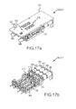
- FIGS. 17 a -17 c are enlarged isometric views, and FIGS. 17 d -17 g are respectively enlarged top and right side, and respectively sections A-A and B-B taken generally along lines A-A and B-B in FIG. 17 d , of a fourth embodiment of a manipulation base;
- FIGS. 18 a and 18 b are enlarged isometric views, and FIG. 18 c -18 e are respectively enlarged left side, bottom and front views of a fourth embodiment of a robotic catheter device cartridge, with FIG. 16 a illustrating an exemplary usage of the robotic catheter device cartridge; and
- FIGS. 19 a -19 c are enlarged isometric views
- FIG. 19 d -19 i are respectively enlarged top, front, bottom, left side, and respectively sections A-A and B-B taken generally along lines A-A and B-B in FIG. 19 f , views of a fourth embodiment of a robotic sheath device cartridge, with FIG. 16 a illustrating an exemplary usage of the robotic sheath device cartridge.
- robotic catheter system 10 (described in detail in commonly owned and copending application titled “Robotic Catheter System”), also referred to as “the system,” may be likened to power steering for a catheter system.
- the system may be used, for example, to manipulate the location and orientation of catheters and sheaths in a heart chamber or in another body cavity. As shown in FIG.
- robotic catheter system 10 may generally incorporate a human input device and control system (referred to as “input control system”) 100 , e.g., a joystick and related controls (described in detail in commonly owned and copending applications titled “Robotic Catheter System Input Device” and “Robotic Catheter System Including Haptic Feedback”), that a user such as an electrophysiologist (EP) may interact with, an electronic control system 200 (described in detail in commonly owned and copending application titled “Robotic Catheter System with Dynamic Response”) that translates motions of the user at the input device into a resulting movement of a catheter tip, and a visualization system 12 that provides a user with real-time or near-real-time positioning information concerning the catheter tip.
- input control system e.g., a joystick and related controls (described in detail in commonly owned and copending applications titled “Robotic Catheter System Input Device” and “Robotic Catheter System Including Haptic Feedback”)
- EP electrophysiologist
- the system may further include closed-loop feedback using an EnSite NavX system 14 and/or optical force transducers, a robotic catheter manipulator assembly 300 (described in detail in commonly owned and copending application titled “Robotic Catheter Manipulator Assembly”) for operating a robotic catheter device cartridge 400 (described below and in detail in commonly owned and copending application titled “Robotic Catheter Rotatable Device Cartridge”), and manipulator support structure 1100 (described in detail in commonly owned and copending application titled “Robotic Catheter System”).
- the system provides the user with a similar type of control provided by a conventional manual system, but allows for repeatable, precise, and dynamic movements.
- An embodiment of robotic catheter system 10 may involve automated catheter movement.
- a user such as an EP, could identify locations (potentially forming a path) on a rendered computer model of the cardiac anatomy.
- the system can be configured to relate those digitally selected points to positions within a patient's actual/physical anatomy, and may command and control the movement of a catheter to defined positions. Once in position, either the user or system could then perform the desired treatment or therapy—which may further be in accordance with a defined algorithm.
- This system could enable full robotic control by using optimized path planning routines together with closed-loop position control.
- the system could automate certain “best-practices,” such as pulling the catheter across the surface, or making contact at an oblique angle.
- input control system 100 will be described briefly.
- Input control system 100 of commonly owned and copending application titled “Robotic Catheter System Input Device,” may generally allow a user to control the movement and advancement of both the catheter and sheath.
- joysticks may be employed, including, without limitation, instrumented traditional catheter handle controls, oversized catheter models, instrumented, user-wearable gloves, and traditional joysticks.
- the joystick may be spring centering so that any movement from the center position causes an incremental movement of the actual catheter tip, or the joystick may work in absolute terms.
- Haptic feedback may also be incorporated to provide a user with a sense of when contact has been made.
- Such features may include, closed-loop feedback using EnSite NavX system 14 for creating realistic cardiac chamber geometries or models, displaying activation timing and voltage data to identify arrhythmias, and guiding precise catheter movement, and/or optical force transducers; active tensioning of “passive” steering wires to reduce the system response time; cumulative ablation while the tip is following a front-to-back ironing motion; and/or reactive/resistive impedance monitoring.
- visualization system 12 will be described briefly.
- visualization system 12 may provide a user with real-time or near-real-time positioning information concerning the catheter tip.
- system 12 may include an EnSite NavX monitor 16 for displaying cardiac chamber geometries or models, displaying activation timing and voltage data to identify arrhythmias, and for facilitating guidance of catheter movement.
- a fluoroscopy monitor 18 may be provided for displaying a real-time x-ray image or for assisting a physician with catheter movement.
- Additional exemplary displays may include an ICE and EP Pruka displays, 20 , 22 , respectively.
- EnSite NavX system 14 will be described briefly.
- EnSite NavX system 14 (described in detail in U.S. Pat. No. 7,263,397, titled “Method and Apparatus for Catheter Navigation and Location and Mapping in the Heart,” incorporated by reference in its entirety) may be provided for creating realistic cardiac chamber geometries or models, displaying activation timing and voltage data to identify arrhythmias, and guiding precise catheter movement. EnSite NavX system 14 may collect electrical data from catheters and use this information to track or navigate their movement and construct three-dimensional (3-D) models of the chamber.
- robotic catheter system 10 may include one or more robotic catheter manipulator assemblies 300 that serve as the mechanical control for the movements or actions of one or more robotic catheter device cartridges 400 (see FIGS. 1, 2, 6 a - 7 f , 11 a - 11 e , 14 a - 14 e and 18 a - 19 i ; described in detail below and in commonly owned and copending application titled “Robotic Catheter Rotatable Device Cartridge”).
- a first embodiment of a manipulator assembly 302 may respectively include both catheter and sheath manipulator mechanisms 304 , 306 .
- the catheter and sheath manipulator mechanisms 304 , 306 may be aligned such that the catheter can pass through the sheath in a coaxial arrangement.
- Each mechanism 304 , 306 may be further capable of independent advancement/retraction (shown generally as directions D 1 and D 2 ) and independent four-wire steering control (e.g., eight total steering wires, comprising four sheath control wires and four catheter control wires), as discussed in detail below.
- a length of stiff material such as, for example, a solid metal rod or fiber reinforced composite, may be incorporated on the interior of the proximal portion of catheter 406 .
- catheter 406 may be proximally stiffened so that the length of the catheter proximally extending from sheath cartridge 404 is less likely to buckle during relative translation, as the entire length of catheter 406 extends into sheath 410 .
- a similarly stiffened proximal portion may be provided when catheter and sheath cartridges are used in the manner described above.
- robotic catheter system 10 which includes one or more robotic catheter manipulator assemblies 300 , includes the first embodiment of robotic catheter manipulator assembly 302 including both catheter and sheath manipulation mechanisms 304 , 306 for manipulating, for example, the first embodiment of catheter and sheath cartridges 402 , 404 (see FIGS. 3 a -3 e ).
- Manipulator assembly 302 may include interconnected/interlocking manipulation bases 308 , 310 for catheter and sheath cartridges 402 , 404 , and likewise may include electrical “handshake” functionality as discussed below.
- Each interlocking manipulation base 308 , 310 may be capable of travel in the longitudinal direction of the catheter/sheath (D 1 , D 2 respectively).
- D 1 and D 2 may each represent a translation of approximately 8 linear inches.
- each interlocking base may be translated by high precision drive mechanisms 312 , 314 .
- Such drive mechanisms may include, for example and without limitation, a motor driven lead screw or ball screw (or alternatively, a belt drive, a rolling ring linear drive, or a piezo motor drive).
- an associated manipulation base 308 , 310 may include a plurality of fingers 316 , 318 , 320 , 322 , (e.g., one per steering wire) that extend or protrude upwardly to contact and interact with the steering wire pins 412 , 414 , 416 , 418 to independently tension select steering wires 420 , 422 , 424 , 426 .
- pins 414 and 418 may be respectively longer than pins 412 and 416 for engagement with extended fingers 318 , 322 .
- Each finger can be configured to be independently actuated by a precision drive mechanism, such as a motor driven ball screw 324 (see FIGS. 4 a -4 d ), and may be outfitted with force sensors to measure corresponding steering wire tension.
- a precision drive mechanism such as a motor driven ball screw 324 (see FIGS. 4 a -4 d ), and may be outfitted with force sensors to measure corresponding steering wire tension.
- Each motor driven ball screw (for both finger control and cartridge translation control) may further include encoders to measure a relative and/or an absolute position of each element of the system.
- Home sensors 358 , 362 , 364 may be provided for respectively guiding catheter and sheath high precision drive mechanisms 312 , 314 and associated manipulation bases 308 , 310 to a safe position.
- motor driven ball screw 324 may include exemplary components such as motor 326 , leadscrew 328 , coupler 330 , bearing mount 332 , strain gauge 334 , radial bearing 336 , and bearing 338 .
- a respective bearing mount 332 and coupler 330 may engage frame 340 of manipulation bases 308 , 310 and a corresponding finger 316 , 318 , 320 or 322 may be mounted adjacent strain gauge 334 (see FIG. 4 b ) for measuring the corresponding steering wire tension.
- manipulation bases 308 , 310 may include exemplary components such as motors 342 , 344 , 346 and 348 , respectively coupled to fingers 316 , 318 , 320 and 322 .
- a motor PC board 350 and a strain gauge PC board 352 may be mounted to frame 340 as shown, and a bearing 354 may be provided for sliding of each manipulation base 308 , 310 on track 356 .
- Manipulator assembly 302 may be disposed in a vertical configuration (see FIG. 1 ) for minimizing both the approach angle of the catheter and the distance the catheter must extend from the patient, or slightly angled from a generally horizontal position (see FIG. 2 ).
- the approach angle and catheter extension distance may be minimized by vertically orienting the backplane of the manipulator head, with the interlocking cartridges positioned at the lower extreme such that they may travel nearly horizontally and substantially in line with the point of entry into the patient (e.g., as generally illustrated in FIG. 1 ).
- the positioning of the manipulator head structure may allow the proximal control of the catheter/sheath to be held closely to the patient's body without substantial structural interference.
- robotic catheter system 10 may include one or more cartridges 400 , with the first embodiment of manipulator assembly 302 including at least two cartridges 402 , 404 , each of which may be respectively designed to control the distal movement of either catheter or sheath 406 , 410 .
- catheter 406 may be substantially connected or affixed to cartridge 402 , so that advancement of cartridge 402 correspondingly advances catheter 406 , and refraction of the cartridge refracts the catheter. As further shown in FIGS.
- each cartridge 402 , 404 may include a plurality of steering wire pins (such as pins 412 , 414 , 416 , 418 ), each rigidly (and independently) connected or affixed to one of a plurality of catheter steering wires 420 , 422 , 424 , 426 in a manner that permits independent tensioning of each steering wire.
- pins 412 , 414 , 416 , 418 may be movable to respectively pull steering wires 420 , 422 , 424 , 426 in the down pull, left pull, right pull and up pull directions.
- each cartridge may include an electrical “handshake” device or component to allow the system to properly identify the cartridge (e.g., by type and/or proper placement/positioning).
- Sheath cartridge 404 ( FIGS. 7 a -7 f ) may be designed in a similar manner as the catheter cartridge 402 ( FIGS. 6 a -6 e ), but will typically be configured to provide for the passage of catheter 406 via sheath opening 408 .
- Manipulator assembly 302 may include a plurality (e.g., as many as ten or more) of independent driving mechanisms (e.g. motor driven ball screws 324 ).
- catheter and sheath cartridges 402 , 404 can be designed to be substantially similar, and in that context a reference to either may relate to both.
- the design of catheter and sheath cartridges 402 , 404 may include upper and lower cartridge housing sections 428 , 430 .
- the system is not generally limited to specific material selection or formation techniques.
- the upper and lower cartridge sections 428 , 430 may be injection molded using a polycarbonate material.
- each steering wire pin 412 , 414 , 416 , 418 may be connected to a separate catheter steering wire 420 , 422 , 424 , 426 , and may be formed of a Teflon-like material such as, for example, Delrin AF. When in contact with the cartridge block 432 , such Teflon-like pins may maintain a low static and dynamic coefficient of friction and avoid the need for additional lubrication.
- catheter and sheath cartridges 402 , 404 may be configured to secure or lock down onto respective interconnecting catheter and sheath manipulation bases 308 , 310 .
- one or more locking/locating pins e.g., 434 in FIGS. 6 c , 6 e , 7 c and 7 f
- the cartridge may engage one or more mating recesses in the base (e.g., 360 in FIG. 5 c ).
- such recesses 360 may include an interference lock such as a spring detent or other locking means.
- such other locking means may include a physical interference that may require affirmative/positive action by the user to release the cartridge.
- cartridges 402 , 404 may be snapped in and released from bases 308 , 310 by exerting sufficient force to remove the cartridges.
- Catheter cartridge 402 (and sheath cartridge 404 ) may also include an electrical connection 436 for catheter instrumentation.
- a user may first manually position catheter and sheath 406 , 410 (with catheter 406 inserted in sheath 410 ) within the vasculature of a patient. Once the devices are roughly positioned in relation to the heart, the user may then engage or connect (e.g., “snap-in”) the catheter cartridge into place on interconnecting/interlocking base 308 , for example, by inserting the locking/locating pins 434 of the cartridge into mating recesses 360 of base 308 .
- each of the plurality of fingers 316 , 318 , 320 , 322 respectively engage steering wire pins 412 , 414 , 416 , 418 , as discussed above.
- Each finger is designed to be actuated in a proximal direction to correspondingly push each respective steering wire pin (note: the embodiment of FIG. 6 b shows pins 418 in a fully extended position before being moved by finger 322 to a fully retracted position, such as that of pin 416 ).
- pushing a steering wire pin in a proximal direction may cause an attached steering wire to tension and thus laterally deflect the distal end of catheter 406 and sheath 410 .
- pushing pins 412 , 414 , 416 , 418 may respectively pull steering wires 420 , 422 , 424 , 426 in the down pull, left pull, right pull and up pull directions.
- manipulator assembly 302 cannot pull the steering wire in a forward direction. That is, when each steering wire pin is actuated, it is only possible to tension the steering wire.
- Override assembly 450 may be provided to operate with manipulator assembly 302 as a secondary means for manually moving pins 412 , 414 , 416 , 418 .
- Override assembly may include fingers 452 , 454 , 456 , 458 that respectively engage with pins 412 , 414 , 416 , 418 of catheter or sheath cartridges 402 , 404 .
- Each finger 452 , 454 , 456 , 458 may include a manual handle 460 for operating a respective finger.
- a user may attach a cartridge 402 , 404 to override assembly 450 by inserting locking/locating pins 434 of the cartridge into mating recesses 462 .
- the user may manually pull an appropriate handle 460 to manually move pins 412 , 414 , 416 , 418 and therefore steering wires 420 , 422 , 424 , 426 .
- robotic catheter system 10 which includes one or more robotic catheter manipulator assemblies 300 , includes the second embodiment of robotic catheter manipulator assembly 500 including both catheter and sheath manipulation mechanisms 504 , 506 for manipulating, for example, a second embodiment of catheter and sheath cartridges 602 , 604 (see FIGS. 11 a -11 e ).
- Manipulator assembly 500 may include interconnected/interlocking manipulation bases 508 , 510 for catheter and sheath cartridges 602 , 604 , and likewise may include electrical “handshake” functionality as discussed below.
- Each interlocking base 508 , 510 may be capable of travel in the longitudinal direction of the catheter/sheath (D 1 , D 2 respectively).
- D 1 and D 2 may each represent a translation of approximately 8 linear inches.
- each interlocking base may be translated by high precision drive mechanisms 512 , 514 .
- Such drive mechanisms may include, for example and without limitation, a motor driven lead screw or ball screw (or alternatively, a belt drive, a rolling ring linear drive, or a piezo motor drive).
- an associated manipulation base 508 , 510 may include a plurality of fingers 516 , 518 , 520 and 522 , (e.g., one per steering wire) that extend or protrude upwardly to contact and interact with the steering wire slider blocks 612 , 614 , 616 , 618 to independently tension select steering wires 620 , 622 , 624 , 626 .
- Each finger can be configured to be independently actuated by a precision drive mechanism, such as a motor driven ball screw 524 (see also FIGS.
- Each motor driven ball screw (for both finger control and cartridge translation control) may further include encoders to measure a relative and/or an absolute position of each element of the system.
- motor driven ball screw 324 may include exemplary components such as motor 326 , leadscrew 328 , coupler 330 , bearing mount 332 , strain gauge 334 , radial bearing 336 , and bearing 338 .
- a respective bearing mount 332 and coupler 330 may engage frame 540 of manipulation bases 508 , 510 and a corresponding finger 516 , 518 , 520 or 522 may be mounted adjacent strain gauge 334 (see FIGS. 4 a -4 d ) for measuring the corresponding steering wire tension.
- manipulation bases 508 , 510 may include exemplary components such as motors 542 , 544 , 546 and 548 , respectively coupled to fingers 516 , 518 , 520 and 522 .
- a bearing 554 may be provided for sliding of each manipulation base 508 , 510 on track 556 .
- a plurality of inductive sensors (e.g. home sensors) 558 may be provided for guiding each manipulation base to a safe position.
- manipulator assembly 500 may be disposed in a vertical configuration (see FIG. 1 ) for minimizing both the approach angle of the catheter and the distance the catheter must extend from the patient, or slightly angled from a generally horizontal position (see FIG. 2 ).
- the approach angle and catheter extension distance may be minimized by vertically orienting the backplane of the manipulator head, with the interlocking cartridges positioned at the lower extreme such that they may travel nearly horizontally and substantially in line with the point of entry into the patient (e.g., as generally illustrated in FIG. 1 ).
- the positioning of the manipulator head structure may allow the proximal control of the catheter/sheath to be held closely to the patient's body without substantial structural interference.
- high-precision drive mechanisms 512 , 514 that are capable of translating each of the catheter and sheath cartridges 602 , 604 may be positioned on the mid-to-upper extreme of the assemblies to allow the respective cartridges to be positioned lower (e.g., with a lower profile) on the manipulator. By holding a close distance, the ingress angle of the catheter/sheath may be minimized, and the manipulator control may be positioned more closely to an insertion site.
- robotic catheter system 10 may include one or more cartridges 400 , with the second embodiment of manipulator assembly 500 including at least two cartridges 602 , 604 , each of which may be respectively designed to control the distal movement of either the catheter or the sheath.
- catheter cartridge 602 catheter 606 may be substantially connected or affixed to cartridge 602 , so that advancement of cartridge 602 correspondingly advances catheter 606 , and refraction of the cartridge refracts the catheter. As further shown in FIGS.
- each cartridge 602 , 604 may include slider blocks (e.g., 612 , 614 , 616 , 618 ), each rigidly (and independently) connected or affixed to one of a plurality of catheter steering wires (e.g., 620 , 622 , 624 , 626 ) in a manner that permits independent tensioning of each steering wire.
- Each slider block 612 , 614 , 616 , 618 may be slidably disposed on a respective rod 636 , 638 , 640 , 642 .
- the cartridge may be provided as a disposable item that is capable of being easily positioned (e.g., snapped) into place in an overall assembly.
- the cartridge may include an electrical “handshake” device or component to allow the system to properly identify the cartridge (e.g., by type and/or proper placement/positioning).
- Sheath cartridge 604 may be designed in a similar manner as the catheter cartridge 602 , but will typically be configured to provide for the passage of catheter 606 .
- Manipulator assembly 500 may include a plurality (e.g., as many as ten or more) of independent driving mechanisms (e.g. motor driven ball screws 524 ).
- the catheter and sheath cartridge can be designed to be substantially similar, and in that context a reference to either may relate to both.
- the design of the catheter, sheath cartridge 602 , 604 may include upper and lower cartridge sections 628 , 630 , and independent slider blocks 612 , 614 , 616 , 618 .
- the system is not generally limited to specific material selection or formation techniques.
- the upper and lower cartridge sections 628 , 630 may be injection molded using a polycarbonate material.
- Each slider block 612 , 614 , 616 , 618 may be connected to a separate catheter steering wire 620 , 622 , 624 , 626 , and may be formed of a Teflon-like material such as, for example, Delrin AF.
- Teflon-like slider blocks When in contact with rods 636 , 638 , 640 , 642 , such Teflon-like slider blocks may maintain a low static and dynamic coefficient of friction and may avoid the need for additional lubrication.
- catheter and sheath cartridges 602 , 604 may be configured to secure or lock down onto respective interconnecting catheter and sheath manipulation bases 508 , 510 .
- one or more locking pins e.g., 632 in FIGS. 11 c and 11 e
- the cartridge may engage one or more mating recesses 560 in the base (see FIG. 10 a ).
- such recesses 560 may include an interference lock such as a spring detent or other locking means.
- such other locking means may include a physical interference that may require affirmative/positive action by the user to release the cartridge.
- cartridge 602 (and 604 ) may include one or more locator pins 634 that are configured to passively fit into mating holes on the base (e.g., 564 in FIG. 10 a ).
- a user may first manually position catheter 606 and sheath 610 (with catheter 606 inserted in sheath 610 ) within the vasculature of a patient. Once the devices are roughly positioned in relation to the heart, the user may then engage or connect (e.g., “snap-in”) the catheter cartridge into place on interconnecting/interlocking base 508 of manipulator assembly 500 , for example, by inserting the locking/locating pins 632 , 634 of the cartridge into mating recesses 560 , 564 of base 508 .
- each of the plurality of fingers 516 , 518 , 520 or 522 may fit into recesses formed between the distal edge of slider blocks 612 , 614 , 616 , 618 and lower cartridge section 630 .
- Such recesses are shown in, for example, FIG. 11 c.
- Each finger may be designed to be actuated in a proximal direction to correspondingly push each respective slider block.
- the slider block can be configured to force the finger to self center on its geometry when contact is first made. Such a centering feature may be facilitated by the contact surface of the slider block.
- the slider block may include an engagement surface (e.g., shaped as a semi-cylindrical recess in the forward facing portion). This surface may be configured to mate or communicate with a matching round portion of a corresponding finger.
- FIGS. 1, 2 and 12 a - 14 e a third embodiment of robotic catheter manipulator assembly 700 will be described in detail.
- robotic catheter system 10 which includes one or more robotic catheter manipulator assemblies 300 , includes the third embodiment of robotic catheter manipulator assembly 700 including both catheter and sheath manipulation mechanisms 704 , 706 for manipulating, for example, a third embodiment of catheter and sheath cartridges 802 , 804 (see FIGS. 14 a -14 e ).
- Manipulator assembly 700 may include interconnected/interlocking manipulation bases 708 , 710 for catheter and sheath cartridges 802 , 804 , and likewise may include electrical “handshake” functionality as discussed below.
- Each interlocking base 708 , 710 may be capable of travel in the longitudinal direction of the catheter/sheath (D 1 , D 2 respectively).
- D 1 and D 2 may each represent a translation of approximately 8 linear inches.
- each interlocking base may be translated by high precision drive mechanisms 712 , 714 .
- Such drive mechanisms may include, for example and without limitation, a motor driven lead screw or ball screw (or alternatively, a belt drive, a rolling ring linear drive, or a piezo motor drive).
- an associated manipulation base 708 , 710 may include a plurality of fingers 716 , 718 , 720 and 722 , (e.g., one per steering wire) that extend or protrude upwardly to contact and interact with the steering wire slider blocks (such as slider blocks 812 , 814 , 816 , 818 ) to independently tension select steering wires 820 , 822 , 824 , 826 .
- Each finger can be configured to be independently actuated by a precision drive mechanism, such as a motor driven ball screw 724 (see also FIGS.
- Each motor driven ball screw (for both finger control and cartridge translation control) may further include encoders to measure a relative and/or an absolute position of each element of the system.
- motor driven ball screw 724 may include exemplary components such as motor 326 , leadscrew 328 , coupler 330 , bearing 332 , strain gauge 334 , radial bearing 336 , and bearing 338 .
- bearing 332 and coupler 330 may engage frame 740 (similar to frame 340 ) of respective bases 708 , 710 and a corresponding finger 716 , 718 , 720 or 722 may be mounted adjacent strain gauge 334 (see FIGS. 4 a -4 d ) for measuring the corresponding steering wire tension.
- bases 708 , 710 may include exemplary components such as motors 742 , 744 , 746 and 748 , respectively coupled to fingers 716 , 718 , 720 and 722 .
- a motor PC board (not shown) and a strain gauge PC board (not shown) may be mounted to frame 740 in a similar manner as bases 308 , 310 , and a bearing 754 may be provided for sliding of bases 708 , 710 on track 756 .
- a plurality of inductive sensors (e.g. home sensors) 758 may be provided for guiding each manipulation base to a safe position.
- manipulator assembly 700 may be disposed in a vertical configuration (see FIG. 1 ) for minimizing both the approach angle of the catheter and the distance the catheter must extend from the patient, or slightly angled from a generally horizontal position (see FIG. 2 ).
- the approach angle and catheter extension distance may be minimized by vertically orienting the backplane of the manipulator head, with the interlocking cartridges positioned at the lower extreme such that they may travel nearly horizontally and substantially in line with the point of entry into the patient (e.g., as generally illustrated in FIG. 1 ).
- the positioning of the manipulator head structure may allow the proximal control of the catheter/sheath to be held closely to the patient's body without substantial structural interference.
- high-precision drive mechanisms 712 , 714 for translating each of the catheter and sheath cartridges 802 , 804 may be positioned generally below the manipulator bases 708 , 710 to allow the respective cartridges to be positioned toward the lower area of the manipulator. By holding a close distance, the ingress angle of the catheter/sheath may be minimized, and the manipulator control may be positioned more closely to an insertion site.
- the third embodiment of robotic catheter manipulator assembly 700 may be usable with a robotic catheter rotatable device cartridge 890 , described in detail in commonly owned and copending application titled “Robotic Catheter Rotatable Device Cartridge.”
- manipulator base 708 may be replaced with a robotic catheter rotatable drive head 892 and a robotic catheter rotatable drive mechanism 894 , described in detail in commonly owned and copending application titled “Robotic Catheter Rotatable Drive Mechanism.”
- robotic catheter system 10 may include one or more cartridges 400 , with the third embodiment of manipulator 700 including at least two cartridges 802 , 804 , each of which may be respectively designed to control the distal movement of either the catheter or the sheath.
- catheter cartridge 802 catheter 806 may be substantially connected or affixed to cartridge 802 , so that advancement of cartridge 802 correspondingly advances catheter 806 , and refraction of the cartridge refracts the catheter. As further shown in FIGS.
- each cartridge 802 , 804 may include slider blocks (e.g., 812 , 814 , 816 , 818 ), each rigidly (and independently) connected or affixed to one of a plurality of catheter steering wires (e.g., 820 , 822 , 824 , 826 ) in a manner that permits independent tensioning of each steering wire.
- the cartridge may be provided as a disposable item that is capable of being easily positioned (e.g., snapped) into place in an overall assembly.
- the cartridge may include an electrical “handshake” device or component to allow the system to properly identify the cartridge (e.g., by type and/or proper placement/positioning).
- Sheath cartridge 804 may be designed in a similar manner as the catheter cartridge 802 , but will typically be configured to provide for the passage of catheter 806 .
- Assembly 700 may include a plurality (e.g., as many as ten or more) of independent driving mechanisms (e.g. motor driven ball screws 724 ).
- the catheter and sheath cartridge can be designed to be substantially similar, and in that context a reference to either may relate to both.
- the design of the catheter/sheath cartridge may include upper and lower cartridge sections 828 , 830 , and independent slider blocks 812 , 814 , 816 , 818 .
- the system is not generally limited to specific material selection or formation techniques.
- the upper and lower cartridge sections 828 , 830 may be injection molded using a polycarbonate material.
- Each slider block 812 , 814 , 816 , 818 may be connected to a separate catheter steering wire 820 , 822 , 824 , 826 , and may be formed of a Teflon-like material such as, for example, Delrin AF.
- Teflon-like slider blocks When in contact with the cartridge housing portions 828 , 830 , such Teflon-like slider blocks may maintain a low static and dynamic coefficient of friction and may avoid the need for additional lubrication.
- catheter and sheath cartridges 802 , 804 may be configured to secure or lock down onto respective interconnecting catheter and sheath manipulation bases 708 , 710 .
- one or more locking pins e.g., 832 in FIGS. 14 a , 14 d and 14 e
- such recesses 760 may include an interference lock such as a spring detent or other locking means.
- such other locking means may include a physical interference that may require affirmative/positive action by the user to release the cartridge. Such action may include or require actuation of a release lever 762 .
- cartridge 802 (and 804 ) may include one or more locator pins 834 that are configured to passively fit into mating holes on the base (e.g., 764 in FIG. 13 a ).
- a user may first manually position catheter 806 and sheath 810 (with catheter 806 inserted in sheath 810 ) within the vasculature of a patient. Once the devices are roughly positioned in relation to the heart, the user may then engage or connect (e.g., “snap-in”) the catheter cartridge into place on interconnecting/interlocking bases 708 , 710 of manipulator assembly 700 , for example, by inserting the locking/locating pins 832 , 834 of the cartridges into mating holes 760 , 764 of respective base 708 , 710 .
- each of the plurality of fingers 716 , 718 , 720 or 722 may fit into recesses formed between the distal edge of slider blocks 812 , 814 , 816 , 818 and a lower portion of the cartridge housing. Such recesses are shown in, for example, FIGS. 14 d and 14 e.
- Each finger may be designed to be actuated in a proximal direction to correspondingly push each respective slider block.
- the slider block can be configured to force the finger to self center on its geometry when contact is first made. Such a centering feature may be facilitated by the contact surface of the slider block.
- the slider block may include an engagement surface (e.g., shaped as a semi-cylindrical recess in the forward facing portion). This surface may be configured to mate or communicate with a matching round portion of a corresponding finger.
- manipulation bases and cartridges described herein allows for integrated force sensors on the control elements, thus facilitating active tensioning and allowing for a “watchdog” system to limit movements that may overstress a catheter.
- the cartridges may be placed on or removed from the manipulator assemblies at any time without jamming, regardless of the position of the manipulation bases. This is readily possible due to the configuration of the control fingers discussed herein that generally approach the cartridges from the de-tensioned side, and further, the home position of the manipulation bases may be designed outside of the cartridge slide block operating range.
- transseptal dilator cartridge 870 an embodiment of a transseptal dilator cartridge 870 will be described in detail.
- Robotic catheter system 10 may be designed to operate with a variety of traditional catheter tools presently available to electrophysiologists.
- An example of a tool that may be configured to work with catheter manipulation base 708 is a transseptal needle/dilator.
- the design of this transseptal dilator cartridge 870 may include a dual-actuated slider block 872 , that may be pushed in a distal direction to actuate a transseptal needle 874 .
- the system may navigate the surrounding sheath into a proper position and angle near the fossa ovalis.
- the rearward carriage holding the transseptal dilator cartridge 870 could then translate in a distal direction to extend the tool beyond the sheath opening.
- needle 874 can extend from its retracted state within dilator 876 and puncture the septum.
- the rearward cartridge could then advance further so dilator 876 may expand the puncture site.
- the fingers e.g., shown as 718 , 720 in FIG. 13 a
- the fingers may operate in a distal direction to cause slider block 872 to move distally.
- Cartridge 870 may be connected and locked into place on the interconnecting base, and the fingers can then be configured to fit into recesses 878 , 880 in slider block 872 .
- needle 874 can be extended/actuated when manipulator fingers 718 , 720 move slider 872 (and attached needle 874 ) in a distal direction. It may likewise be retracted into dilator 876 when slider 872 is moved in a proximal direction.
- the slider may be “actively” moved both distally and proximally to extend and retract the needle, respectively.
- the fingers 718 , 720 of the manipulator may actuate needle 874 by pushing slider block 872 in a proximal direction (similar to the actuation of a catheter steering wire).
- This rearward motion may then be reversed by a pulley mechanism (not shown) to then extend needle 874 beyond the dilator 876 . While this design may require a more complex cartridge, the operation of the manipulator could remain the same as with other steering wire control (e.g., actuation through rearward motion).
- FIGS. 1, 2 and 16 a - 19 i a fourth embodiment of robotic catheter manipulator assembly 900 will be described in detail.
- robotic catheter system 10 which includes one or more robotic catheter manipulator assemblies 300 , includes the fourth embodiment of robotic catheter manipulator assembly 900 including both catheter and sheath manipulation mechanisms 904 , 906 for manipulating, for example, a fourth embodiment of catheter and sheath cartridges 1002 , 1004 .
- Manipulator assembly 900 may include interconnected/interlocking manipulation bases 908 , 910 for catheter and sheath cartridges 1002 , 1004 , and likewise may include electrical “handshake” functionality as discussed below.
- Each interlocking base 908 , 910 may be capable of travel in the longitudinal direction of the catheter/sheath (D 1 , D 2 respectively).
- D 1 and D 2 may each represent a translation of approximately 8 linear inches.
- each interlocking base may be translated by high precision drive mechanisms 912 , 914 .
- Such drive mechanisms may include, for example and without limitation, a motor driven lead screw or ball screw (or alternatively, a belt drive, a rolling ring linear drive, or a piezo motor drive).
- an associated manipulation base 908 , 910 may include a plurality of slider blocks 916 , 918 , 920 and 922 , (e.g., one per steering wire) that extend up to the surface of base plate 923 and are contacted by steering wire fingers 1012 , 1014 , 1016 , 1018 to independently tension select steering wires 1020 , 1022 , 1024 , 1026 .
- Each finger can be configured to be independently actuated by a precision drive mechanism, such as a motor driven ball screw 924 (see also FIGS.
- Each motor driven ball screw (for both finger control and cartridge translation control) may further include encoders to measure a relative and/or an absolute position of each element of the system.
- motor driven ball screw 924 may include exemplary components such as motor 326 , leadscrew 328 , coupler 330 , bearing 332 , strain gauge 334 , radial bearing 336 , and bearing 338 .
- bearing 332 and coupler 330 may engage frame 940 (similar to frame 340 ) of bases 908 , 910 and corresponding slider blocks 916 , 918 , 920 or 922 may be mounted adjacent strain gauge 334 (see FIGS. 4 a -4 d ) for measuring the corresponding steering wire tension.
- bases 908 , 910 may include exemplary components such as motors 942 , 944 , 946 and 948 , respectively coupled to slider blocks 916 , 918 , 920 and 922 .
- a motor PC board (not shown) and a strain gauge PC board (not shown) may be mounted to frame 940 in a similar manner as bases 308 , 310 (see FIGS. 5 a -5 c ), and a bearing 954 may be provided for sliding of bases 908 , 910 on track 956 .
- a plurality of inductive sensors (e.g. home sensors) 958 may be provided for guiding each manipulation base to a safe position.
- manipulator assembly 900 may be disposed in a vertical configuration (see FIG. 1 ) for minimizing both the approach angle of the catheter and the distance the catheter must extend from the patient, or slightly angled from a generally horizontal position (see FIG. 2 ).
- the approach angle and catheter extension distance may be minimized by vertically orienting the backplane of the manipulator head, with the interlocking cartridges positioned at the lower extreme such that they may travel nearly horizontally and substantially in line with the point of entry into the patient (e.g., as generally illustrated in FIG. 1 ).
- the positioning of the manipulator head structure may allow the proximal control of the catheter/sheath to be held closely to the patient's body without substantial structural interference.
- high-precision drive mechanisms 912 , 914 for translating each of the catheter and sheath cartridges 1002 , 1004 may be positioned generally below manipulator bases 908 , 910 to allow the respective cartridges to be positioned toward the lower area of the manipulator. By holding a close distance, the ingress angle of the catheter/sheath may be minimized, and the manipulator control may be positioned more closely to an insertion site.
- all electronics may be disposed on the back side of manipulator assembly 900 to render assembly 900 generally self contained, requiring only power and communication wires to be connected thereto.
- the fourth embodiment of robotic catheter manipulator assembly 900 may be usable with a robotic catheter rotatable device cartridge 1090 , described in detail in commonly owned and copending application titled “Robotic Catheter Rotatable Device Cartridge.”
- manipulator base 908 may be replaced with a robotic catheter rotatable drive head 1092 and a robotic catheter rotatable drive mechanism 1094 , described in detail in commonly owned and copending application titled “Robotic Catheter Rotatable Drive Mechanism.”
- robotic catheter system 10 may include one or more cartridges 400 , with the fourth embodiment of manipulator 900 including at least two cartridges 1002 , 1004 , each of which may be respectively designed to control the distal movement of either the catheter or the sheath.
- catheter 1006 may be substantially connected or affixed to cartridge 1002 , so that advancement of cartridge 1002 correspondingly advances catheter 1006 , and refraction of the cartridge refracts the catheter. As further shown in FIGS.
- each cartridge 1002 , 1004 may include steering wire fingers 1012 , 1014 , 1016 , 1018 , each rigidly (and independently) connected or affixed to one of a plurality of catheter steering wires (e.g., 1020 , 1022 , 1024 , 1026 ) in a manner that permits independent tensioning of each steering wire.
- the cartridge may be provided as a disposable item that is capable of being easily positioned (e.g., snapped) into place in an overall assembly.
- the cartridge may include an electrical “handshake” device or component to allow the system to properly identify the cartridge (e.g., by type and/or proper placement/positioning).
- Sheath cartridge 1004 may be designed in a similar manner as catheter cartridge 1002 , but will typically be configured to provide for the passage of catheter 1006 .
- Manipulator assembly 902 may include a plurality (e.g., as many as ten or more) of independent driving mechanisms (e.g. motor driven ball screws 924 ).
- the catheter and sheath cartridges can be designed to be substantially similar, and in that context a reference to either may relate to both.
- the design of the catheter/sheath cartridges may include upper and lower cartridge sections 1028 , 1030 , and independent steering wire fingers 1012 , 1014 , 1016 , 1018 .
- the system is not generally limited to specific material selection or formation techniques.
- the upper and lower cartridge sections 1028 , 1030 may be injection molded using a polycarbonate material.
- Each steering wire finger 1012 , 1014 , 1016 , 1018 via its slider 1019 may be connected to a separate catheter steering wire 1020 , 1022 , 1024 , 1026 , and may be formed of a Teflon-like material such as, for example, Delrin AF.
- Teflon-like sliders 1019 and steering wire fingers may maintain a low static and dynamic coefficient of friction and may avoid the need for additional lubrication.
- catheter and sheath cartridges 1002 , 1004 may be configured to secure or lock down onto respective interconnecting catheter and sheath manipulation bases 908 , 910 .
- one or more locking pins e.g., 1032 in FIGS. 18 e , 19 h
- the cartridge may engage one or more mating recesses 960 in the base (see FIG. 17 a ).
- such recesses 960 may include an interference lock such as a spring detent or other locking means.
- such other locking means may include a physical interference that may require affirmative/positive action by the user to release the cartridge.
- cartridge 1002 (and 1004 ) may include one or more locator pins 1034 that are configured to passively fit into mating holes on the base (e.g., 964 in FIG. 17 a ).
- a user may first manually position catheter 1006 and sheath 1010 (with catheter 1006 inserted in sheath 1010 ) within the vasculature of a patient. Once the devices are roughly positioned in relation to the heart, the user may then engage or connect (e.g., “snap-in”) the catheter cartridge into place on interconnecting/interlocking bases of a manipulator, for example, by inserting the locking/locating pins 1032 , 1034 of the cartridge into mating holes 960 , 964 of manipulation bases 908 , 910 .
- each of the plurality of steering wire fingers 1012 , 1014 , 1016 , 1018 may fit into recesses formed at the distal edge of slider blocks 916 , 918 , 920 , 922 .
- Such recesses are shown in, for example, FIG. 17 b.
- Each slider block may be designed to be actuated in a proximal direction to correspondingly push each respective finger.
- the finger can be configured to force the slider block to self center on its geometry when contact is first made. Such a centering feature may be facilitated by the contact surface of the slider block.
- the slider block may include an engagement surface (e.g., shaped as a semi-cylindrical recess in the forward facing portion). This surface may be configured to mate or communicate with a matching round portion of a corresponding finger.
- manipulator assembly 900 cannot pull the steering wire in a forward direction. That is, when each finger is actuated, it is only possible to tension the steering wire. Furthermore, because the push-actuation of each slider block occurs near that block's bottom surface, a moment may be imposed on the block. Because such moment may increase the likelihood of the block binding during travel, the length of the block may be optimized to reduce or minimize contact forces between the block and base plate 923 .
- robotic catheter system 10 may be useful for a variety of procedures and in connection with a variety of tools and/or catheters.
- tools and/or catheters may include, without limitation, spiral catheters, ablation catheters, mapping catheters, balloon catheters, needle/dilator tools, cutting tools, cauterizing tools, and/or gripping tools.
- the system may additionally include a means of identifying the nature and/or type of catheter/tool cartridge that is installed for use, and/or position or connection related information.
- the system may also automatically access/obtain additional information about the cartridge, such as, without limitation, its creation date, serial number, sterilization date, prior uses, etc.
- each cartridge may contain a chip (e.g., an EEPROM chip) that can be electrically interfaced by the manipulator head.
- a chip e.g., an EEPROM chip
- Such a chip could, for instance, be programmed during the manufacturing process and may electronically store various data, such as the make; model; serial number; creation date; and/or other special features associated with the cartridge or tool.
- the chip may contain other worthwhile information, such as an indication of previous use, catheter specific calibration data, and/or any other information that may relate to the safety or performance of the particular device.
- a detection means such as an optical or magnetic sensor, may initially detect the presence of the cartridge. Once presence is detected, the manipulator may energize a chip and initiate data/signal retrieval. Such retrieved data/signal may then be used by the system to control or alter various features and/or displays based on the type of device and/or information provided. While one embodiment may use a chip (e.g., EEPROM), due to its design flexibility, another embodiment may include a wireless transmission device, such as an RFID, which may be employed to facilitate the data storage/transfer instead of, or in addition to a chip.
- a chip e.g., EEPROM
- RFID wireless transmission device
- joinder references do not necessarily infer that two elements are directly connected and in fixed relation to each other. It is intended that all matter contained in the above description or shown in the accompanying drawings shall be interpreted as illustrative only and not as limiting. Changes in detail or structure may be made without departing from the invention as defined in the appended claims.
Abstract
A robotic catheter device cartridge may include a finger or a slider block generally disposed in a channel and engaged with a steering wire. The steering wire may control movement of a component having the steering wire engaged thereto when the finger or the slider block is linearly driven in a predetermined direction. The cartridge may be a transseptal cartridge having a transseptal needle connected thereto, a catheter cartridge having a catheter connected thereto, or a sheath cartridge having a sheath connected thereto.
Description
This application is a continuation of U.S. application Ser. No. 12/347,835, filed 31 Dec. 2008, which claims the benefit of priority to U.S. Provisional Application Nos. 61/040,143, filed Mar. 27, 2008 and 61/099,904, filed Sep. 24, 2008, the entire disclosures of which are incorporated herein by reference.
a. Field of the Invention
This invention relates to a robotic catheter system and method for automated control of a catheter and related components. In particular, the instant invention relates to a removable robotic catheter device cartridge usable with a robotic catheter system for manipulating a catheter and related components, for example, for diagnostic, therapeutic, mapping and ablative procedures.
b. Background Art
Electrophysiology catheters are used in a variety of diagnostic and/or therapeutic medical procedures to correct conditions such as atrial arrhythmia, including for example, ectopic atrial tachycardia, atrial fibrillation, and atrial flutter. Arrhythmia can create a variety of dangerous conditions including irregular heart rates, loss of synchronous atrioventricular contractions and stasis of blood flow which can lead to a variety of ailments and even death.
Typically in a procedure, a catheter is manipulated through a patient's vasculature to, for example, a patient's heart, and carries one or more electrodes which may be used for mapping, ablation, diagnosis, or other treatments. Once at the intended site, treatment may include radio frequency (RF) ablation, cryoablation, lasers, chemicals, high-intensity focused ultrasound, etc. An ablation catheter imparts such ablative energy to cardiac tissue to create a lesion in the cardiac tissue. This lesion disrupts undesirable electrical pathways and thereby limits or prevents stray electrical signals that lead to arrhythmias. As readily apparent, such treatment requires precise control of the catheter during manipulation to and at the treatment site, which can invariably be a function of a user's skill level.
The inventors herein have thus recognized a need for a system and method for precise and dynamic automated control of a catheter and its related components, for example, for diagnostic, therapeutic, mapping and ablative procedures, that will minimize and/or eliminate procedural variability due to a user's skill level. The inventors herein have also recognized a need for a system and method for performing user-specified procedures at the patient site or from a remote location.
It is desirable to provide a system and method for precise and dynamic automated control of a catheter and its related components. In particular, it is desirable to provide a system and method for precise and dynamic automated control, for example, for diagnostic, therapeutic, mapping and ablative procedures, that will minimize and/or eliminate procedural variability due to a user's skill level, and minimize and/or eliminate radiation exposure from fluoroscopy by moving the staff away from the patient, with the procedures being optionally performed at the patient site or from a remote location.
A system and method for precise and dynamic automated control of a catheter and its related components may include a robotic catheter device cartridge that eliminates backlash, “slop” and other discontinuities in catheter and sheath control that can make computer control thereof difficult. The system and method, as discussed herein, may generally include a linear mechanism between the drive means and catheter tip, as opposed to a rotary system which operates on the radius change of a wire for controlling a catheter tip, thus significantly enhancing the overall control function.
A system and method for precise and dynamic automated control of a catheter and its related components may include a robotic catheter device cartridge including a finger or a slider block generally disposed in a channel and engaged with a steering wire. The steering wire may control movement of a component having the steering wire engaged thereto when the finger or the slider block is linearly driven in a predetermined direction.
For the robotic catheter device cartridge described above, in one embodiment, the cartridge may be a catheter cartridge and the component may be a catheter connected thereto. Alternatively, the cartridge may be a sheath cartridge and the component may be a sheath connected thereto. In one embodiment, the robotic catheter device cartridge may include one or more recesses in a catheter manipulation base for releasably connecting the catheter cartridge or the catheter cartridge for engagement with one or more complementary locator detents on the other one of the catheter manipulation base or the catheter cartridge for alignment of the catheter cartridge relative to the catheter manipulation base. In one embodiment, the robotic catheter device cartridge may include one or more recesses in a catheter manipulation base for releasably connecting the catheter cartridge or the catheter cartridge for engagement with one or more complementary locking detents on the other one of the catheter manipulation base or the catheter cartridge for releasable locking of the catheter cartridge with the catheter manipulation base.
For the robotic catheter device cartridge described above, in one embodiment, the cartridge may include one or more recesses in a sheath manipulation base for releasably connecting the sheath cartridge or the sheath cartridge for engagement with one or more complementary locator detents on the other one of the sheath manipulation base or the sheath cartridge for alignment of the sheath cartridge relative to the sheath manipulation base. In one embodiment, the robotic catheter device cartridge may include one or more recesses in a sheath manipulation base for releasably connecting the sheath cartridge or the sheath cartridge for engagement with one or more complementary locking detents on the other one of the sheath manipulation base or the sheath cartridge for releasable locking of the sheath cartridge with the sheath manipulation base.
For the robotic catheter device cartridge described above, in one embodiment, the cartridge may be a catheter cartridge and the component may be a catheter connected thereto and may include at least two steering wires connected generally to a distal end of the catheter along a circumference of the catheter to control movement of the catheter. In one embodiment, the cartridge may be a sheath cartridge and the component may be a sheath connected thereto and may include at least two steering wires connected generally to a distal end of the sheath along a circumference of the sheath to control movement of the sheath. In one embodiment, the finger or slider block may be linearly driveable to pull the steering wire generally linearly along a length of the steering wire. The linear driveability of the finger or slider block may generally eliminate any backlash or discontinuities during driving thereof.
For the robotic catheter device cartridge described above, in one embodiment, the cartridge may include one or more first engageable members in a catheter manipulation base for releasably connecting the catheter cartridge or the catheter cartridge for mating with one or more complementary engageable members on the other one of the catheter manipulation base or the catheter cartridge for alignment of or releasable locking of the catheter cartridge with the catheter manipulation base. In one embodiment, the cartridge may include one or more first engageable members in a sheath manipulation base for releasably connecting the sheath cartridge or the sheath cartridge for mating with one or more complementary engageable members on the other one of the sheath manipulation base or the sheath cartridge for alignment of or releasable locking of the sheath cartridge with the sheath manipulation base. In one embodiment, the component may be a surgically insertable device.
In one embodiment, a system and method for precise and dynamic automated control of a catheter and its related components may include a robotic catheter device cartridge including a first element operatively engaged with the cartridge and operatively engageable with a second element of a manipulation base. One or more of the first and second elements may be slidably engageable with the cartridge and/or the manipulation base. The manipulation base may releasably connect the cartridge. The first or second elements may be engaged with a steering wire for controlling movement of a component having the steering wire engaged thereto when the first or second element is linearly driven in a predetermined direction.
For the robotic catheter device cartridge described above, in one embodiment, the cartridge may be a catheter cartridge and the component may be a catheter connected thereto, or a sheath cartridge and the component may be a sheath connected thereto. In one embodiment, the robotic catheter device cartridge may include one or more recesses in the manipulation base or the cartridge for engagement with one or more complementary locator detents on the other one of the manipulation base or the cartridge for alignment of the cartridge relative to the manipulation base. In one embodiment, the robotic catheter device cartridge may include one or more recesses in the manipulation base or the cartridge for engagement with one or more complementary locking detents on the other one of the manipulation base or the cartridge for releasable locking of the cartridge with the manipulation base.
For the robotic catheter device cartridge described above, in one embodiment, the cartridge may be a catheter cartridge and the component may be a catheter connected thereto and may include at least two steering wires connected generally to a distal end of the catheter along a circumference of the catheter to control movement of the catheter. In one embodiment, the cartridge may be a sheath cartridge and the component may be a sheath connected thereto and may include at least two steering wires connected generally to a distal end of the sheath along a circumference of the sheath to control movement of the sheath. In one embodiment, one of the first or second elements may be a finger and the other one of the first or second elements may be a slider block. In one embodiment, one of the first or second elements may be a finger and the other one of the first or second elements may be a pin. In one embodiment, one of the first or second elements may be slidably disposed in a channel. In one embodiment, one or more of the first and second elements may include a self-centering notch for facilitating predetermined engagement with the other one of the first and second elements, and for minimizing friction and attaining greater controllability. In one embodiment, the component may be a surgically insertable device. The cartridge, in one embodiment, may be magnetically connectable to a manipulation base for releasably connecting the cartridge.
In one embodiment, a system and method for precise and dynamic automated control of a catheter and its related components may include a robotic catheter device cartridge including a finger and/or a slider block generally disposed in a channel and engageable with a slider block and/or a finger on a manipulation base. The manipulation base may releasably connect the cartridge. The fingers and/or the slider blocks may be linearly driveable in a predetermined direction for operating the cartridge.
For the robotic catheter device cartridge described above, in one embodiment, the cartridge may be a catheter cartridge having a catheter connected thereto, a sheath cartridge having a sheath connected thereto, or a transseptal cartridge having a transseptal needle connected thereto. In one embodiment, the robotic catheter device cartridge may include one or more recesses in the manipulation base or the cartridge for engagement with one or more complementary locator detents on the other one of the manipulation base or the cartridge for alignment of the cartridge relative to the manipulation base. In one embodiment, the robotic catheter device cartridge may include one or more recesses in the manipulation base or the cartridge for engagement with one or more complementary locking detents on the other one of the manipulation base or the cartridge for releasable locking of the cartridge with the manipulation base.
For the robotic catheter device cartridge described above, in one embodiment, the robotic catheter device cartridge may include a first element operatively engaged with the cartridge and operatively engageable with a second element of a manipulation base. One or more of the first and second elements may be slidably engageable with one or more of the cartridge and the manipulation base. The manipulation base may releasably connect the cartridge. One or more of the first and second elements may be linearly driveable in a predetermined direction for operating the cartridge. In one embodiment, the cartridge may be a catheter cartridge having a catheter connected thereto, a sheath cartridge having a sheath connected thereto, or a transseptal cartridge having a transseptal needle connected thereto.
For the robotic catheter device cartridge described above, in one embodiment, the robotic catheter device cartridge may include one or more recesses in the manipulation base or the cartridge for engagement with one or more complementary locator detents on the other one of the manipulation base or the cartridge for alignment of the cartridge relative to the manipulation base. In one embodiment, the robotic catheter device cartridge may include one or more recesses in the manipulation base or the cartridge for engagement with one or more complementary locking detents on the other one of the manipulation base or the cartridge for releasable locking of the cartridge with the manipulation base. One of the first and second elements may be a finger and the other one of the first and second elements may be a slider block. Alternatively, one of the first and second elements may be a finger and the other one of the first and second elements may be a pin. In one embodiment, one of the first and second elements may be slidably disposed in a channel. In one embodiment, one of the first and second elements may include a self-centering notch for facilitating predetermined engagement with the other one of the first and second elements, and for minimizing friction and attaining greater controllability.
In one embodiment, a system and method for precise and dynamic automated control of a catheter and its related components may include a robotic catheter device cartridge including a first catheter element operatively engaged with a catheter cartridge and operatively engageable with a second catheter element of a catheter manipulation base. One or more of the first and second catheter elements may be slidably engageable with one or more of the catheter cartridge and the catheter manipulation base. The catheter manipulation base may releasably connect the catheter cartridge. One or more of the first and second catheter elements may be linearly driveable in a predetermined direction for operating the catheter cartridge. A first sheath element may be operatively engaged with a sheath cartridge and operatively engageable with a second sheath element of a sheath manipulation base. One or more of the first and second sheath elements may be slidably engageable with one or more of the sheath cartridge and the sheath manipulation base. The sheath manipulation base may releasably connect the sheath cartridge. One or more of the first and second sheath elements may be linearly driveable in a predetermined direction for operating the sheath cartridge.
For the robotic catheter device cartridge described above, in one embodiment, the robotic catheter device cartridge may include one or more recesses in the catheter manipulation base or the catheter cartridge for engagement with one or more complementary locator detents on the other one of the catheter manipulation base or the catheter cartridge for alignment of the catheter cartridge relative to the catheter manipulation base. In another embodiment, the robotic catheter device cartridge may include one or more further recesses in the sheath manipulation base or the sheath cartridge for engagement with one or more further complementary locator detents on the other one of the sheath manipulation base or the sheath cartridge for alignment of the sheath cartridge relative to the sheath manipulation base.
For the robotic catheter device cartridge described above, in one embodiment, the robotic catheter device cartridge may include one or more recesses in the catheter manipulation base or the catheter cartridge for engagement with one or more complementary locking detents on the other one of the catheter manipulation base or the catheter cartridge for releasable locking of the catheter cartridge with the catheter manipulation base. One or more recesses in the sheath manipulation base or the sheath cartridge may engage with one or more complementary locking detents on the other one of the sheath manipulation base or the sheath cartridge for releasable locking of the sheath cartridge with the sheath manipulation base.
For the robotic catheter device cartridge described above, in one embodiment, the robotic catheter device cartridge may include the first or second catheter element being a finger and the other one of the first or second catheter element being a slider block. Alternatively, the first or second sheath element may be a finger and the other one of the first or second sheath elements may be a slider block. In one embodiment, the first or second catheter element may be a finger and the other one of the first or second catheter element may be a pin (or a telescoping tube arrangement). Alternatively, the first or second sheath element may be a finger and the other one of the first or second sheath element may be a pin (or a telescoping tube arrangement).
For the robotic catheter device cartridge described above, in one embodiment, the catheter and sheath cartridges may respectively include a catheter and a sheath mounted thereto, with the catheter including a stiffened section between the catheter and sheath cartridges to prevent buckling of the catheter. In one embodiment, one or more of the slidably engageable catheter and sheath elements may be slidably disposed in a channel. In one embodiment, one or more of the first and second catheter and sheath elements may include a self-centering notch for facilitating predetermined engagement with the other one of the first and second catheter and sheath elements, and for minimizing friction and attaining greater controllability. The catheter and sheath cartridges, in an embodiment, may respectively include a catheter and a sheath mounted thereto, and the linear driveability of the catheter and sheath elements generally eliminates any backlash or discontinuities during driving of the catheter and sheath elements. In one embodiment, the catheter or sheath cartridges may include a release lever for release of the respective cartridge from a respective catheter or sheath manipulation base.
The foregoing and other aspects, features, details, utilities and advantages of the present invention will be apparent from reading the following description and claims, and from reviewing the accompanying drawings.
Referring now to the drawings wherein like reference numerals are used to identify identical components in the various views, an embodiment of robotic catheter system 10 (described in detail in commonly owned and copending application titled “Robotic Catheter System”), also referred to as “the system,” may be likened to power steering for a catheter system. The system may be used, for example, to manipulate the location and orientation of catheters and sheaths in a heart chamber or in another body cavity. As shown in FIG. 1 and described in detail below, robotic catheter system 10 may generally incorporate a human input device and control system (referred to as “input control system”) 100, e.g., a joystick and related controls (described in detail in commonly owned and copending applications titled “Robotic Catheter System Input Device” and “Robotic Catheter System Including Haptic Feedback”), that a user such as an electrophysiologist (EP) may interact with, an electronic control system 200 (described in detail in commonly owned and copending application titled “Robotic Catheter System with Dynamic Response”) that translates motions of the user at the input device into a resulting movement of a catheter tip, and a visualization system 12 that provides a user with real-time or near-real-time positioning information concerning the catheter tip. The system may further include closed-loop feedback using an EnSite NavX system 14 and/or optical force transducers, a robotic catheter manipulator assembly 300 (described in detail in commonly owned and copending application titled “Robotic Catheter Manipulator Assembly”) for operating a robotic catheter device cartridge 400 (described below and in detail in commonly owned and copending application titled “Robotic Catheter Rotatable Device Cartridge”), and manipulator support structure 1100 (described in detail in commonly owned and copending application titled “Robotic Catheter System”). The system provides the user with a similar type of control provided by a conventional manual system, but allows for repeatable, precise, and dynamic movements. The respective disclosures of the above-identified and other commonly owned and copending applications discussed in this application are incorporated herein by reference.
An embodiment of robotic catheter system 10 may involve automated catheter movement. A user, such as an EP, could identify locations (potentially forming a path) on a rendered computer model of the cardiac anatomy. The system can be configured to relate those digitally selected points to positions within a patient's actual/physical anatomy, and may command and control the movement of a catheter to defined positions. Once in position, either the user or system could then perform the desired treatment or therapy—which may further be in accordance with a defined algorithm. This system could enable full robotic control by using optimized path planning routines together with closed-loop position control. Furthermore, the system could automate certain “best-practices,” such as pulling the catheter across the surface, or making contact at an oblique angle.
Referring to FIG. 1 , input control system 100 will be described briefly.
Referring to FIG. 1 , electronic control system 200 will be described briefly.
As discussed in detail in commonly owned and copending applications titled “Robotic Catheter System Input Device,” and “Robotic Catheter System with Dynamic Response,” many additional features may be included with embodiments of the system to, for example, improve the accuracy or effectiveness of the system. Such features may include, closed-loop feedback using EnSite NavX system 14 for creating realistic cardiac chamber geometries or models, displaying activation timing and voltage data to identify arrhythmias, and guiding precise catheter movement, and/or optical force transducers; active tensioning of “passive” steering wires to reduce the system response time; cumulative ablation while the tip is following a front-to-back ironing motion; and/or reactive/resistive impedance monitoring.
Referring to FIG. 1 , visualization system 12 will be described briefly.
As discussed in further detail in commonly owned and copending application titled “Robotic Catheter System,” visualization system 12 may provide a user with real-time or near-real-time positioning information concerning the catheter tip. In an exemplary embodiment, system 12 may include an EnSite NavX monitor 16 for displaying cardiac chamber geometries or models, displaying activation timing and voltage data to identify arrhythmias, and for facilitating guidance of catheter movement. A fluoroscopy monitor 18 may be provided for displaying a real-time x-ray image or for assisting a physician with catheter movement. Additional exemplary displays may include an ICE and EP Pruka displays, 20, 22, respectively.
Referring to FIG. 1 , EnSite NavX system 14 will be described briefly.
EnSite NavX system 14 (described in detail in U.S. Pat. No. 7,263,397, titled “Method and Apparatus for Catheter Navigation and Location and Mapping in the Heart,” incorporated by reference in its entirety) may be provided for creating realistic cardiac chamber geometries or models, displaying activation timing and voltage data to identify arrhythmias, and guiding precise catheter movement. EnSite NavX system 14 may collect electrical data from catheters and use this information to track or navigate their movement and construct three-dimensional (3-D) models of the chamber.
Referring to FIGS. 1-3 e and 6 a-7 f, the catheter and sheath configuration of robotic catheter manipulator assembly 300 and robotic catheter device cartridges 400 will be described in detail.
As generally shown in FIGS. 1, 2, 3 a-3 e, 9 a-9 d, 12 a-12 m and 16 a-16 m, and described in detail below, robotic catheter system 10 may include one or more robotic catheter manipulator assemblies 300 that serve as the mechanical control for the movements or actions of one or more robotic catheter device cartridges 400 (see FIGS. 1, 2, 6 a-7 f, 11 a-11 e, 14 a-14 e and 18 a-19 i; described in detail below and in commonly owned and copending application titled “Robotic Catheter Rotatable Device Cartridge”).
As generally shown in FIGS. 1 and 3 a-3 e and discussed in greater detail below and in commonly owned and copending application titled “Robotic Catheter Manipulator Assembly,” a first embodiment of a manipulator assembly 302 may respectively include both catheter and sheath manipulator mechanisms 304, 306. In this arrangement, the catheter and sheath manipulator mechanisms 304, 306 may be aligned such that the catheter can pass through the sheath in a coaxial arrangement. Each mechanism 304, 306 may be further capable of independent advancement/retraction (shown generally as directions D1 and D2) and independent four-wire steering control (e.g., eight total steering wires, comprising four sheath control wires and four catheter control wires), as discussed in detail below.
With a configuration of robotic catheter system 10, such as shown in FIGS. 1 and 3 a-3 e, there will be relative travel of a first embodiment of catheter and sheath cartridges 402, 404 and relative movement associated with a portion of a catheter 406 between the two cartridges 402, 404. For many embodiments, there may be a water-tight fit of a proximal sheath opening 408, which can sometimes create resistance to catheter advancement. In order to help eliminate/reduce the potential issue of columnar buckling of catheter 406, a length of stiff material, such as, for example, a solid metal rod or fiber reinforced composite, may be incorporated on the interior of the proximal portion of catheter 406. Such a material may locally increase the catheter's bending stiffness and provide enhanced buckling support. Thus catheter 406 may be proximally stiffened so that the length of the catheter proximally extending from sheath cartridge 404 is less likely to buckle during relative translation, as the entire length of catheter 406 extends into sheath 410.
For the manipulator and cartridge assemblies discussed below, a similarly stiffened proximal portion may be provided when catheter and sheath cartridges are used in the manner described above.
Referring to FIGS. 1-7 f, the first embodiment of robotic catheter manipulator assembly 302 will be described in detail.
As generally shown in FIGS. 1-7 f, robotic catheter system 10 which includes one or more robotic catheter manipulator assemblies 300, includes the first embodiment of robotic catheter manipulator assembly 302 including both catheter and sheath manipulation mechanisms 304, 306 for manipulating, for example, the first embodiment of catheter and sheath cartridges 402, 404 (see FIGS. 3a-3e ). Manipulator assembly 302 may include interconnected/interlocking manipulation bases 308, 310 for catheter and sheath cartridges 402, 404, and likewise may include electrical “handshake” functionality as discussed below. Each interlocking manipulation base 308, 310 may be capable of travel in the longitudinal direction of the catheter/sheath (D1, D2 respectively). In an embodiment, D1 and D2 may each represent a translation of approximately 8 linear inches. As shown in FIGS. 3a, 3c and 3e , each interlocking base may be translated by high precision drive mechanisms 312, 314. Such drive mechanisms may include, for example and without limitation, a motor driven lead screw or ball screw (or alternatively, a belt drive, a rolling ring linear drive, or a piezo motor drive).
As shown in FIGS. 3e, 5a-5c, 6d and 7e , for each cartridge 402, 404, an associated manipulation base 308, 310 may include a plurality of fingers 316, 318, 320, 322, (e.g., one per steering wire) that extend or protrude upwardly to contact and interact with the steering wire pins 412, 414, 416, 418 to independently tension select steering wires 420, 422, 424, 426. As shown in FIGS. 3e and 6d , pins 414 and 418 may be respectively longer than pins 412 and 416 for engagement with extended fingers 318, 322. Each finger can be configured to be independently actuated by a precision drive mechanism, such as a motor driven ball screw 324 (see FIGS. 4a-4d ), and may be outfitted with force sensors to measure corresponding steering wire tension. Each motor driven ball screw (for both finger control and cartridge translation control) may further include encoders to measure a relative and/or an absolute position of each element of the system. Home sensors 358, 362, 364 may be provided for respectively guiding catheter and sheath high precision drive mechanisms 312, 314 and associated manipulation bases 308, 310 to a safe position.
Referring to FIGS. 4a-4d , motor driven ball screw 324 may include exemplary components such as motor 326, leadscrew 328, coupler 330, bearing mount 332, strain gauge 334, radial bearing 336, and bearing 338. As shown in FIGS. 5a-5c , a respective bearing mount 332 and coupler 330 may engage frame 340 of manipulation bases 308, 310 and a corresponding finger 316, 318, 320 or 322 may be mounted adjacent strain gauge 334 (see FIG. 4b ) for measuring the corresponding steering wire tension.
Referring to FIGS. 5a-5c , manipulation bases 308, 310 may include exemplary components such as motors 342, 344, 346 and 348, respectively coupled to fingers 316, 318, 320 and 322. A motor PC board 350 and a strain gauge PC board 352 may be mounted to frame 340 as shown, and a bearing 354 may be provided for sliding of each manipulation base 308, 310 on track 356.
Referring to FIGS. 1-3 e and 5 a-7 f, the first embodiment of catheter and sheath cartridges 402, 404 will be described in detail.
As briefly discussed above, robotic catheter system 10 may include one or more cartridges 400, with the first embodiment of manipulator assembly 302 including at least two cartridges 402, 404, each of which may be respectively designed to control the distal movement of either catheter or sheath 406, 410. With respect to catheter cartridge 402, catheter 406 may be substantially connected or affixed to cartridge 402, so that advancement of cartridge 402 correspondingly advances catheter 406, and refraction of the cartridge refracts the catheter. As further shown in FIGS. 6a-6e and 7a-7f and briefly discussed above, in an embodiment, each cartridge 402, 404 may include a plurality of steering wire pins (such as pins 412, 414, 416, 418), each rigidly (and independently) connected or affixed to one of a plurality of catheter steering wires 420, 422, 424, 426 in a manner that permits independent tensioning of each steering wire. In a particular embodiment, pins 412, 414, 416, 418 may be movable to respectively pull steering wires 420, 422, 424, 426 in the down pull, left pull, right pull and up pull directions. The cartridges may be provided as a disposable item that is capable of being easily positioned (e.g., snapped) into place in an overall assembly. In an embodiment, as discussed in detail below, each cartridge may include an electrical “handshake” device or component to allow the system to properly identify the cartridge (e.g., by type and/or proper placement/positioning). Sheath cartridge 404 (FIGS. 7a-7f ) may be designed in a similar manner as the catheter cartridge 402 (FIGS. 6a-6e ), but will typically be configured to provide for the passage of catheter 406 via sheath opening 408. Manipulator assembly 302 may include a plurality (e.g., as many as ten or more) of independent driving mechanisms (e.g. motor driven ball screws 324).
For some embodiments, catheter and sheath cartridges 402, 404 can be designed to be substantially similar, and in that context a reference to either may relate to both. For example, as shown in FIGS. 6a-7f , the design of catheter and sheath cartridges 402, 404 may include upper and lower cartridge housing sections 428, 430. The system is not generally limited to specific material selection or formation techniques. However, in an embodiment, the upper and lower cartridge sections 428, 430 may be injection molded using a polycarbonate material. As discussed above, each steering wire pin 412, 414, 416, 418 may be connected to a separate catheter steering wire 420, 422, 424, 426, and may be formed of a Teflon-like material such as, for example, Delrin AF. When in contact with the cartridge block 432, such Teflon-like pins may maintain a low static and dynamic coefficient of friction and avoid the need for additional lubrication.
Referring to FIGS. 6a-7f , catheter and sheath cartridges 402, 404 may be configured to secure or lock down onto respective interconnecting catheter and sheath manipulation bases 308, 310. In order to couple cartridges 402, 404 with bases 308, 310, one or more locking/locating pins (e.g., 434 in FIGS. 6c, 6e, 7c and 7f ) on the cartridge may engage one or more mating recesses in the base (e.g., 360 in FIG. 5c ). In an embodiment, such recesses 360 may include an interference lock such as a spring detent or other locking means. In an embodiment, such other locking means may include a physical interference that may require affirmative/positive action by the user to release the cartridge. In the embodiment illustrated, cartridges 402, 404 may be snapped in and released from bases 308, 310 by exerting sufficient force to remove the cartridges. Catheter cartridge 402 (and sheath cartridge 404) may also include an electrical connection 436 for catheter instrumentation.
In an embodiment, a user (e.g. an EP) may first manually position catheter and sheath 406, 410 (with catheter 406 inserted in sheath 410) within the vasculature of a patient. Once the devices are roughly positioned in relation to the heart, the user may then engage or connect (e.g., “snap-in”) the catheter cartridge into place on interconnecting/interlocking base 308, for example, by inserting the locking/locating pins 434 of the cartridge into mating recesses 360 of base 308. When the cartridge is interconnected with the base, each of the plurality of fingers 316, 318, 320, 322 respectively engage steering wire pins 412, 414, 416, 418, as discussed above. Each finger is designed to be actuated in a proximal direction to correspondingly push each respective steering wire pin (note: the embodiment of FIG. 6b shows pins 418 in a fully extended position before being moved by finger 322 to a fully retracted position, such as that of pin 416).
With sufficiently rigid coupling between each steering wire pin and a corresponding steering wire, pushing a steering wire pin in a proximal direction may cause an attached steering wire to tension and thus laterally deflect the distal end of catheter 406 and sheath 410. For example, as discussed above, pushing pins 412, 414, 416, 418 may respectively pull steering wires 420, 422, 424, 426 in the down pull, left pull, right pull and up pull directions. Moreover, in such an embodiment, because there is no rigid connection between each finger and its associated steering wire pin, manipulator assembly 302 cannot pull the steering wire in a forward direction. That is, when each steering wire pin is actuated, it is only possible to tension the steering wire.
Referring to FIGS. 8a and 8b , an override assembly 450 will be described in detail.
Referring to FIGS. 1, 2 and 9 a-11 e, a second embodiment of robotic catheter manipulator assembly 500 will be described in detail.
As generally shown in FIGS. 1, 2 and 9 a-11 e, robotic catheter system 10 which includes one or more robotic catheter manipulator assemblies 300, includes the second embodiment of robotic catheter manipulator assembly 500 including both catheter and sheath manipulation mechanisms 504, 506 for manipulating, for example, a second embodiment of catheter and sheath cartridges 602, 604 (see FIGS. 11a-11e ). Manipulator assembly 500 may include interconnected/interlocking manipulation bases 508, 510 for catheter and sheath cartridges 602, 604, and likewise may include electrical “handshake” functionality as discussed below. Each interlocking base 508, 510 may be capable of travel in the longitudinal direction of the catheter/sheath (D1, D2 respectively). In an embodiment, D1 and D2 may each represent a translation of approximately 8 linear inches. As shown in FIG. 9a (similar to the first embodiment of manipulator assembly 302 for FIGS. 3a, 3c and 3e ), each interlocking base may be translated by high precision drive mechanisms 512, 514. Such drive mechanisms may include, for example and without limitation, a motor driven lead screw or ball screw (or alternatively, a belt drive, a rolling ring linear drive, or a piezo motor drive).
As shown in FIGS. 9a-11e , for each cartridge 602, 604, an associated manipulation base 508, 510 may include a plurality of fingers 516, 518, 520 and 522, (e.g., one per steering wire) that extend or protrude upwardly to contact and interact with the steering wire slider blocks 612, 614, 616, 618 to independently tension select steering wires 620, 622, 624, 626. Each finger can be configured to be independently actuated by a precision drive mechanism, such as a motor driven ball screw 524 (see also FIGS. 4a-4d and description above for a detailed description of ball screw 324), and may be outfitted with force sensors to measure corresponding steering wire tension. Each motor driven ball screw (for both finger control and cartridge translation control) may further include encoders to measure a relative and/or an absolute position of each element of the system.
As discussed above, referring to FIGS. 4a-4d , motor driven ball screw 324 may include exemplary components such as motor 326, leadscrew 328, coupler 330, bearing mount 332, strain gauge 334, radial bearing 336, and bearing 338. As shown in FIGS. 10a-10g , a respective bearing mount 332 and coupler 330 may engage frame 540 of manipulation bases 508, 510 and a corresponding finger 516, 518, 520 or 522 may be mounted adjacent strain gauge 334 (see FIGS. 4a-4d ) for measuring the corresponding steering wire tension.
Referring to FIGS. 10a-10g , manipulation bases 508, 510 may include exemplary components such as motors 542, 544, 546 and 548, respectively coupled to fingers 516, 518, 520 and 522. A bearing 554 may be provided for sliding of each manipulation base 508, 510 on track 556. A plurality of inductive sensors (e.g. home sensors) 558 may be provided for guiding each manipulation base to a safe position.
As with manipulator assembly 302, manipulator assembly 500 may be disposed in a vertical configuration (see FIG. 1 ) for minimizing both the approach angle of the catheter and the distance the catheter must extend from the patient, or slightly angled from a generally horizontal position (see FIG. 2 ). In the vertical configuration of FIG. 1 , the approach angle and catheter extension distance may be minimized by vertically orienting the backplane of the manipulator head, with the interlocking cartridges positioned at the lower extreme such that they may travel nearly horizontally and substantially in line with the point of entry into the patient (e.g., as generally illustrated in FIG. 1 ). In such an embodiment, with the backplane of the manipulator head vertically oriented, the positioning of the manipulator head structure may allow the proximal control of the catheter/sheath to be held closely to the patient's body without substantial structural interference. In an embodiment, high- precision drive mechanisms 512, 514 that are capable of translating each of the catheter and sheath cartridges 602, 604 may be positioned on the mid-to-upper extreme of the assemblies to allow the respective cartridges to be positioned lower (e.g., with a lower profile) on the manipulator. By holding a close distance, the ingress angle of the catheter/sheath may be minimized, and the manipulator control may be positioned more closely to an insertion site.
Referring to FIGS. 1, 2 and 9 a-11 e, the second embodiment of catheter and sheath cartridges 602, 604 will be described in detail.
As briefly discussed above, robotic catheter system 10 may include one or more cartridges 400, with the second embodiment of manipulator assembly 500 including at least two cartridges 602, 604, each of which may be respectively designed to control the distal movement of either the catheter or the sheath. With respect to catheter cartridge 602, catheter 606 may be substantially connected or affixed to cartridge 602, so that advancement of cartridge 602 correspondingly advances catheter 606, and refraction of the cartridge refracts the catheter. As further shown in FIGS. 11a-11e and discussed above, in an embodiment, each cartridge 602, 604 may include slider blocks (e.g., 612, 614, 616, 618), each rigidly (and independently) connected or affixed to one of a plurality of catheter steering wires (e.g., 620, 622, 624, 626) in a manner that permits independent tensioning of each steering wire. Each slider block 612, 614, 616, 618 may be slidably disposed on a respective rod 636, 638, 640, 642. The cartridge may be provided as a disposable item that is capable of being easily positioned (e.g., snapped) into place in an overall assembly. In an embodiment, as discussed in detail below, the cartridge may include an electrical “handshake” device or component to allow the system to properly identify the cartridge (e.g., by type and/or proper placement/positioning). Sheath cartridge 604 may be designed in a similar manner as the catheter cartridge 602, but will typically be configured to provide for the passage of catheter 606. Manipulator assembly 500 may include a plurality (e.g., as many as ten or more) of independent driving mechanisms (e.g. motor driven ball screws 524).
For some embodiments, the catheter and sheath cartridge can be designed to be substantially similar, and in that context a reference to either may relate to both. For example, as shown in FIGS. 11a-11e , the design of the catheter, sheath cartridge 602, 604 may include upper and lower cartridge sections 628, 630, and independent slider blocks 612, 614, 616, 618. The system is not generally limited to specific material selection or formation techniques. However, in an embodiment, the upper and lower cartridge sections 628, 630, may be injection molded using a polycarbonate material. Each slider block 612, 614, 616, 618 may be connected to a separate catheter steering wire 620, 622, 624, 626, and may be formed of a Teflon-like material such as, for example, Delrin AF. When in contact with rods 636, 638, 640, 642, such Teflon-like slider blocks may maintain a low static and dynamic coefficient of friction and may avoid the need for additional lubrication.
Referring to FIGS. 11a-11e , catheter and sheath cartridges 602, 604 may be configured to secure or lock down onto respective interconnecting catheter and sheath manipulation bases 508, 510. To couple cartridge 602 (and 604) with base 508 (and 510), one or more locking pins (e.g., 632 in FIGS. 11c and 11e ) on the cartridge may engage one or more mating recesses 560 in the base (see FIG. 10a ). In an embodiment, such recesses 560 may include an interference lock such as a spring detent or other locking means. In an embodiment, such other locking means may include a physical interference that may require affirmative/positive action by the user to release the cartridge. Such action may include or require actuation of a release lever 562. Additionally, as shown in FIGS. 11c and 11e , cartridge 602 (and 604) may include one or more locator pins 634 that are configured to passively fit into mating holes on the base (e.g., 564 in FIG. 10a ).
In an embodiment, a user (e.g. an EP) may first manually position catheter 606 and sheath 610 (with catheter 606 inserted in sheath 610) within the vasculature of a patient. Once the devices are roughly positioned in relation to the heart, the user may then engage or connect (e.g., “snap-in”) the catheter cartridge into place on interconnecting/interlocking base 508 of manipulator assembly 500, for example, by inserting the locking/locating pins 632, 634 of the cartridge into mating recesses 560, 564 of base 508. When the cartridge is interconnected with the base, each of the plurality of fingers 516, 518, 520 or 522 may fit into recesses formed between the distal edge of slider blocks 612, 614, 616, 618 and lower cartridge section 630. Such recesses are shown in, for example, FIG. 11 c.
Each finger may be designed to be actuated in a proximal direction to correspondingly push each respective slider block. The slider block can be configured to force the finger to self center on its geometry when contact is first made. Such a centering feature may be facilitated by the contact surface of the slider block. For example, as shown in FIG. 11c , the slider block may include an engagement surface (e.g., shaped as a semi-cylindrical recess in the forward facing portion). This surface may be configured to mate or communicate with a matching round portion of a corresponding finger.
With sufficiently rigid coupling between each slider block and a corresponding steering wire, pushing a slider block in a proximal direction may cause an attached steering wire to tension and thus laterally deflect the distal end of the catheter and sheath 606, 610. Moreover, in such an embodiment, because there is no rigid connection between each finger and its associated slider block, the manipulator assembly 500 cannot pull the steering wire in a forward direction. That is, when each block is actuated, it is only possible to tension the steering wire.
Referring to FIGS. 1, 2 and 12 a-14 e, a third embodiment of robotic catheter manipulator assembly 700 will be described in detail.
As generally shown in FIGS. 1, 2 and 12 a-14 e, robotic catheter system 10 which includes one or more robotic catheter manipulator assemblies 300, includes the third embodiment of robotic catheter manipulator assembly 700 including both catheter and sheath manipulation mechanisms 704, 706 for manipulating, for example, a third embodiment of catheter and sheath cartridges 802, 804 (see FIGS. 14a-14e ). Manipulator assembly 700 may include interconnected/interlocking manipulation bases 708, 710 for catheter and sheath cartridges 802, 804, and likewise may include electrical “handshake” functionality as discussed below. Each interlocking base 708, 710 may be capable of travel in the longitudinal direction of the catheter/sheath (D1, D2 respectively). In an embodiment, D1 and D2 may each represent a translation of approximately 8 linear inches. As shown in FIG. 12a (similar to the first embodiment of manipulator assembly 302 for FIGS. 3a, 3c and 3e ), each interlocking base may be translated by high precision drive mechanisms 712, 714. Such drive mechanisms may include, for example and without limitation, a motor driven lead screw or ball screw (or alternatively, a belt drive, a rolling ring linear drive, or a piezo motor drive).
As shown in FIGS. 12a-12i and 13a-13g , for each cartridge 802, 804, an associated manipulation base 708, 710 may include a plurality of fingers 716, 718, 720 and 722, (e.g., one per steering wire) that extend or protrude upwardly to contact and interact with the steering wire slider blocks (such as slider blocks 812, 814, 816, 818) to independently tension select steering wires 820, 822, 824, 826. Each finger can be configured to be independently actuated by a precision drive mechanism, such as a motor driven ball screw 724 (see also FIGS. 4a-4d and description above for a detailed description of ball screw 324), and may be outfitted with force sensors to measure corresponding steering wire tension. Each motor driven ball screw (for both finger control and cartridge translation control) may further include encoders to measure a relative and/or an absolute position of each element of the system.
As discussed above, referring to FIGS. 4a-4d , motor driven ball screw 724 (and ball screw 324) may include exemplary components such as motor 326, leadscrew 328, coupler 330, bearing 332, strain gauge 334, radial bearing 336, and bearing 338. As shown in FIG. 13a , bearing 332 and coupler 330 may engage frame 740 (similar to frame 340) of respective bases 708, 710 and a corresponding finger 716, 718, 720 or 722 may be mounted adjacent strain gauge 334 (see FIGS. 4a-4d ) for measuring the corresponding steering wire tension.
Referring to FIGS. 13a-13g , bases 708, 710 may include exemplary components such as motors 742, 744, 746 and 748, respectively coupled to fingers 716, 718, 720 and 722. A motor PC board (not shown) and a strain gauge PC board (not shown) may be mounted to frame 740 in a similar manner as bases 308, 310, and a bearing 754 may be provided for sliding of bases 708, 710 on track 756. A plurality of inductive sensors (e.g. home sensors) 758 may be provided for guiding each manipulation base to a safe position.
As with manipulator assembly 302, manipulator assembly 700 may be disposed in a vertical configuration (see FIG. 1 ) for minimizing both the approach angle of the catheter and the distance the catheter must extend from the patient, or slightly angled from a generally horizontal position (see FIG. 2 ). In the vertical configuration of FIG. 1 , the approach angle and catheter extension distance may be minimized by vertically orienting the backplane of the manipulator head, with the interlocking cartridges positioned at the lower extreme such that they may travel nearly horizontally and substantially in line with the point of entry into the patient (e.g., as generally illustrated in FIG. 1 ). In such an embodiment, with the backplane of the manipulator head vertically oriented, the positioning of the manipulator head structure may allow the proximal control of the catheter/sheath to be held closely to the patient's body without substantial structural interference. In an embodiment, high-precision drive mechanisms 712, 714 for translating each of the catheter and sheath cartridges 802, 804 may be positioned generally below the manipulator bases 708, 710 to allow the respective cartridges to be positioned toward the lower area of the manipulator. By holding a close distance, the ingress angle of the catheter/sheath may be minimized, and the manipulator control may be positioned more closely to an insertion site.
Referring to FIGS. 1, 2 and 12 a-12 m, particularly FIGS. 12j-12m , the third embodiment of robotic catheter manipulator assembly 700 may be usable with a robotic catheter rotatable device cartridge 890, described in detail in commonly owned and copending application titled “Robotic Catheter Rotatable Device Cartridge.” As shown in FIG. 12m , manipulator base 708 may be replaced with a robotic catheter rotatable drive head 892 and a robotic catheter rotatable drive mechanism 894, described in detail in commonly owned and copending application titled “Robotic Catheter Rotatable Drive Mechanism.”
Referring to FIGS. 1, 2 and 14 a-14 e, the third embodiment of catheter and sheath cartridges 802, 804 will be described in detail.
As briefly discussed above, robotic catheter system 10 may include one or more cartridges 400, with the third embodiment of manipulator 700 including at least two cartridges 802, 804, each of which may be respectively designed to control the distal movement of either the catheter or the sheath. With respect to catheter cartridge 802, catheter 806 may be substantially connected or affixed to cartridge 802, so that advancement of cartridge 802 correspondingly advances catheter 806, and refraction of the cartridge refracts the catheter. As further shown in FIGS. 14a-14e and discussed above, in an embodiment, each cartridge 802, 804 may include slider blocks (e.g., 812, 814, 816, 818), each rigidly (and independently) connected or affixed to one of a plurality of catheter steering wires (e.g., 820, 822, 824, 826) in a manner that permits independent tensioning of each steering wire. The cartridge may be provided as a disposable item that is capable of being easily positioned (e.g., snapped) into place in an overall assembly. In an embodiment, as discussed in detail below, the cartridge may include an electrical “handshake” device or component to allow the system to properly identify the cartridge (e.g., by type and/or proper placement/positioning). Sheath cartridge 804 may be designed in a similar manner as the catheter cartridge 802, but will typically be configured to provide for the passage of catheter 806. Assembly 700 may include a plurality (e.g., as many as ten or more) of independent driving mechanisms (e.g. motor driven ball screws 724).
For some embodiments, the catheter and sheath cartridge can be designed to be substantially similar, and in that context a reference to either may relate to both. For example, as shown in FIGS. 14a-14e , the design of the catheter/sheath cartridge may include upper and lower cartridge sections 828, 830, and independent slider blocks 812, 814, 816, 818. The system is not generally limited to specific material selection or formation techniques. However, in an embodiment, the upper and lower cartridge sections 828, 830 may be injection molded using a polycarbonate material. Each slider block 812, 814, 816, 818 may be connected to a separate catheter steering wire 820, 822, 824, 826, and may be formed of a Teflon-like material such as, for example, Delrin AF. When in contact with the cartridge housing portions 828, 830, such Teflon-like slider blocks may maintain a low static and dynamic coefficient of friction and may avoid the need for additional lubrication.
Referring to FIGS. 12a-14e and as discussed above, catheter and sheath cartridges 802, 804 may be configured to secure or lock down onto respective interconnecting catheter and sheath manipulation bases 708, 710. To couple cartridge 802 (and 804) with base 708 (and 710), one or more locking pins (e.g., 832 in FIGS. 14a, 14d and 14e ) on the cartridge may engage one or more mating recesses 760 in the base (see FIG. 13a ). In an embodiment, such recesses 760 may include an interference lock such as a spring detent or other locking means. In an embodiment, such other locking means may include a physical interference that may require affirmative/positive action by the user to release the cartridge. Such action may include or require actuation of a release lever 762. Additionally, as shown in FIGS. 14c, 14d and 14e , cartridge 802 (and 804) may include one or more locator pins 834 that are configured to passively fit into mating holes on the base (e.g., 764 in FIG. 13a ).
In an embodiment, a user (e.g. an EP) may first manually position catheter 806 and sheath 810 (with catheter 806 inserted in sheath 810) within the vasculature of a patient. Once the devices are roughly positioned in relation to the heart, the user may then engage or connect (e.g., “snap-in”) the catheter cartridge into place on interconnecting/interlocking bases 708, 710 of manipulator assembly 700, for example, by inserting the locking/locating pins 832, 834 of the cartridges into mating holes 760, 764 of respective base 708, 710. When the cartridge is interconnected with the base, each of the plurality of fingers 716, 718, 720 or 722 may fit into recesses formed between the distal edge of slider blocks 812, 814, 816, 818 and a lower portion of the cartridge housing. Such recesses are shown in, for example, FIGS. 14d and 14 e.
Each finger may be designed to be actuated in a proximal direction to correspondingly push each respective slider block. The slider block can be configured to force the finger to self center on its geometry when contact is first made. Such a centering feature may be facilitated by the contact surface of the slider block. For example, as shown in FIGS. 14d and 14e , the slider block may include an engagement surface (e.g., shaped as a semi-cylindrical recess in the forward facing portion). This surface may be configured to mate or communicate with a matching round portion of a corresponding finger.
With sufficiently rigid coupling between each slider block and a corresponding steering wire, pushing a slider block in a proximal direction may cause an attached steering wire to tension and thus laterally deflect the distal end of the catheter and sheath 806, 810. Moreover, in such an embodiment, because there is no rigid connection between each finger and its associated slider block, the manipulator assembly 700 cannot pull the steering wire in a forward direction. That is, when each block is actuated, it is only possible to tension the steering wire. Furthermore, because the push-actuation of each slider block occurs near that block's bottom surface, a moment may be imposed on the block. Because such a moment may increase the likelihood of the block binding during travel, the length of the block may be optimized to reduce or minimize contact forces between the block and the cartridge housing.
The generally linear architecture of manipulation bases and cartridges described herein (including the embodiments discussed below) allows for integrated force sensors on the control elements, thus facilitating active tensioning and allowing for a “watchdog” system to limit movements that may overstress a catheter. Further, as illustrated, the cartridges may be placed on or removed from the manipulator assemblies at any time without jamming, regardless of the position of the manipulation bases. This is readily possible due to the configuration of the control fingers discussed herein that generally approach the cartridges from the de-tensioned side, and further, the home position of the manipulation bases may be designed outside of the cartridge slide block operating range.
Referring to FIGS. 1, 2, 12 a-12 i and 15 a-15 d, an embodiment of a transseptal dilator cartridge 870 will be described in detail.
In an embodiment, to actuate slider block 872, the fingers (e.g., shown as 718, 720 in FIG. 13a ) of the manipulator may operate in a distal direction to cause slider block 872 to move distally. Cartridge 870 may be connected and locked into place on the interconnecting base, and the fingers can then be configured to fit into recesses 878, 880 in slider block 872. With such an embodiment, needle 874 can be extended/actuated when manipulator fingers 718, 720 move slider 872 (and attached needle 874) in a distal direction. It may likewise be retracted into dilator 876 when slider 872 is moved in a proximal direction. In such an embodiment, the slider may be “actively” moved both distally and proximally to extend and retract the needle, respectively.
In a further embodiment, the fingers 718, 720 of the manipulator may actuate needle 874 by pushing slider block 872 in a proximal direction (similar to the actuation of a catheter steering wire). This rearward motion, however, may then be reversed by a pulley mechanism (not shown) to then extend needle 874 beyond the dilator 876. While this design may require a more complex cartridge, the operation of the manipulator could remain the same as with other steering wire control (e.g., actuation through rearward motion).
Referring to FIGS. 1, 2 and 16 a-19 i, a fourth embodiment of robotic catheter manipulator assembly 900 will be described in detail.
As generally shown in FIGS. 1, 2, 16 a-16 i and 17 a-19 i robotic catheter system 10 which includes one or more robotic catheter manipulator assemblies 300, includes the fourth embodiment of robotic catheter manipulator assembly 900 including both catheter and sheath manipulation mechanisms 904, 906 for manipulating, for example, a fourth embodiment of catheter and sheath cartridges 1002, 1004. Manipulator assembly 900 may include interconnected/interlocking manipulation bases 908, 910 for catheter and sheath cartridges 1002, 1004, and likewise may include electrical “handshake” functionality as discussed below. Each interlocking base 908, 910 may be capable of travel in the longitudinal direction of the catheter/sheath (D1, D2 respectively). In an embodiment, D1 and D2 may each represent a translation of approximately 8 linear inches. As shown in FIG. 16a (similar to the first to third embodiments of manipulator assemblies 302, 500, 700), each interlocking base may be translated by high precision drive mechanisms 912, 914. Such drive mechanisms may include, for example and without limitation, a motor driven lead screw or ball screw (or alternatively, a belt drive, a rolling ring linear drive, or a piezo motor drive).
As shown in FIGS. 16a-16i and 17a-19i , for each cartridge 1002, 1004, an associated manipulation base 908, 910 may include a plurality of slider blocks 916, 918, 920 and 922, (e.g., one per steering wire) that extend up to the surface of base plate 923 and are contacted by steering wire fingers 1012, 1014, 1016, 1018 to independently tension select steering wires 1020, 1022, 1024, 1026. Each finger can be configured to be independently actuated by a precision drive mechanism, such as a motor driven ball screw 924 (see also FIGS. 4a-4d and description above for a detailed description of ball screw 324), and may be outfitted with force sensors to measure corresponding steering wire tension. Each motor driven ball screw (for both finger control and cartridge translation control) may further include encoders to measure a relative and/or an absolute position of each element of the system.
As discussed above, referring to FIGS. 4a-4d , motor driven ball screw 924 (and ball screw 324) may include exemplary components such as motor 326, leadscrew 328, coupler 330, bearing 332, strain gauge 334, radial bearing 336, and bearing 338. As shown in FIG. 17a , bearing 332 and coupler 330 may engage frame 940 (similar to frame 340) of bases 908, 910 and corresponding slider blocks 916, 918, 920 or 922 may be mounted adjacent strain gauge 334 (see FIGS. 4a-4d ) for measuring the corresponding steering wire tension.
Referring to FIGS. 17a-17g , bases 908, 910 may include exemplary components such as motors 942, 944, 946 and 948, respectively coupled to slider blocks 916, 918, 920 and 922. A motor PC board (not shown) and a strain gauge PC board (not shown) may be mounted to frame 940 in a similar manner as bases 308, 310 (see FIGS. 5a-5c ), and a bearing 954 may be provided for sliding of bases 908, 910 on track 956. A plurality of inductive sensors (e.g. home sensors) 958 may be provided for guiding each manipulation base to a safe position.
As with manipulator assembly 302, manipulator assembly 900 may be disposed in a vertical configuration (see FIG. 1 ) for minimizing both the approach angle of the catheter and the distance the catheter must extend from the patient, or slightly angled from a generally horizontal position (see FIG. 2 ). In the vertical configuration of FIG. 1 , the approach angle and catheter extension distance may be minimized by vertically orienting the backplane of the manipulator head, with the interlocking cartridges positioned at the lower extreme such that they may travel nearly horizontally and substantially in line with the point of entry into the patient (e.g., as generally illustrated in FIG. 1 ). In such an embodiment, with the backplane of the manipulator head vertically oriented, the positioning of the manipulator head structure may allow the proximal control of the catheter/sheath to be held closely to the patient's body without substantial structural interference. In an embodiment, high-precision drive mechanisms 912, 914 for translating each of the catheter and sheath cartridges 1002, 1004 may be positioned generally below manipulator bases 908, 910 to allow the respective cartridges to be positioned toward the lower area of the manipulator. By holding a close distance, the ingress angle of the catheter/sheath may be minimized, and the manipulator control may be positioned more closely to an insertion site. Further, as shown in FIG. 16b , all electronics may be disposed on the back side of manipulator assembly 900 to render assembly 900 generally self contained, requiring only power and communication wires to be connected thereto.
Referring to FIGS. 1, 2 and 16 a-16 m, particularly FIGS. 16j-16m , the fourth embodiment of robotic catheter manipulator assembly 900 may be usable with a robotic catheter rotatable device cartridge 1090, described in detail in commonly owned and copending application titled “Robotic Catheter Rotatable Device Cartridge.” As shown in FIG. 16m , manipulator base 908 may be replaced with a robotic catheter rotatable drive head 1092 and a robotic catheter rotatable drive mechanism 1094, described in detail in commonly owned and copending application titled “Robotic Catheter Rotatable Drive Mechanism.”
Referring to FIGS. 1, 2 and 16 a-19 i, the fourth embodiment of catheter and sheath cartridges 1002, 1004 will be described in detail.
As briefly discussed above, robotic catheter system 10 may include one or more cartridges 400, with the fourth embodiment of manipulator 900 including at least two cartridges 1002, 1004, each of which may be respectively designed to control the distal movement of either the catheter or the sheath. With respect to catheter cartridge 1002, catheter 1006 may be substantially connected or affixed to cartridge 1002, so that advancement of cartridge 1002 correspondingly advances catheter 1006, and refraction of the cartridge refracts the catheter. As further shown in FIGS. 18a-19i and discussed above, in an embodiment, each cartridge 1002, 1004 may include steering wire fingers 1012, 1014, 1016, 1018, each rigidly (and independently) connected or affixed to one of a plurality of catheter steering wires (e.g., 1020, 1022, 1024, 1026) in a manner that permits independent tensioning of each steering wire. The cartridge may be provided as a disposable item that is capable of being easily positioned (e.g., snapped) into place in an overall assembly. In an embodiment, as discussed in detail below, the cartridge may include an electrical “handshake” device or component to allow the system to properly identify the cartridge (e.g., by type and/or proper placement/positioning). Sheath cartridge 1004 may be designed in a similar manner as catheter cartridge 1002, but will typically be configured to provide for the passage of catheter 1006. Manipulator assembly 902 may include a plurality (e.g., as many as ten or more) of independent driving mechanisms (e.g. motor driven ball screws 924).
For some embodiments, the catheter and sheath cartridges can be designed to be substantially similar, and in that context a reference to either may relate to both. For example, as shown in FIGS. 18a-19i , the design of the catheter/sheath cartridges may include upper and lower cartridge sections 1028, 1030, and independent steering wire fingers 1012, 1014, 1016, 1018. The system is not generally limited to specific material selection or formation techniques. However, in an embodiment, the upper and lower cartridge sections 1028, 1030 may be injection molded using a polycarbonate material. Each steering wire finger 1012, 1014, 1016, 1018 via its slider 1019 may be connected to a separate catheter steering wire 1020, 1022, 1024, 1026, and may be formed of a Teflon-like material such as, for example, Delrin AF. When in contact with the cartridge housing portions 1028, 1030, such Teflon-like sliders 1019 and steering wire fingers may maintain a low static and dynamic coefficient of friction and may avoid the need for additional lubrication.
Referring to FIGS. 18a-19i , catheter and sheath cartridges 1002, 1004 may be configured to secure or lock down onto respective interconnecting catheter and sheath manipulation bases 908, 910. To couple cartridge 1002 (and 1004) with base 908 (and 910), one or more locking pins (e.g., 1032 in FIGS. 18e, 19h ) on the cartridge may engage one or more mating recesses 960 in the base (see FIG. 17a ). In an embodiment, such recesses 960 may include an interference lock such as a spring detent or other locking means. In an embodiment, such other locking means may include a physical interference that may require affirmative/positive action by the user to release the cartridge. Such action may include or require actuation of a release lever 962. Additionally, as shown in FIGS. 18e and 19h , cartridge 1002 (and 1004) may include one or more locator pins 1034 that are configured to passively fit into mating holes on the base (e.g., 964 in FIG. 17a ).
In an embodiment, a user (e.g. an EP) may first manually position catheter 1006 and sheath 1010 (with catheter 1006 inserted in sheath 1010) within the vasculature of a patient. Once the devices are roughly positioned in relation to the heart, the user may then engage or connect (e.g., “snap-in”) the catheter cartridge into place on interconnecting/interlocking bases of a manipulator, for example, by inserting the locking/locating pins 1032, 1034 of the cartridge into mating holes 960, 964 of manipulation bases 908, 910. When the cartridge is interconnected with the base, each of the plurality of steering wire fingers 1012, 1014, 1016, 1018 may fit into recesses formed at the distal edge of slider blocks 916, 918, 920, 922. Such recesses are shown in, for example, FIG. 17 b.
Each slider block may be designed to be actuated in a proximal direction to correspondingly push each respective finger. The finger can be configured to force the slider block to self center on its geometry when contact is first made. Such a centering feature may be facilitated by the contact surface of the slider block. For example, as shown in FIG. 17b , the slider block may include an engagement surface (e.g., shaped as a semi-cylindrical recess in the forward facing portion). This surface may be configured to mate or communicate with a matching round portion of a corresponding finger.
With sufficiently rigid coupling between each finger and a corresponding steering wire, pushing a finger in a proximal direction may cause an attached steering wire to tension and thus laterally deflect the distal end of catheter and sheath 1006, 1010. Moreover, in such an embodiment, because there is no rigid connection between each finger and its associated slider block, manipulator assembly 900 cannot pull the steering wire in a forward direction. That is, when each finger is actuated, it is only possible to tension the steering wire. Furthermore, because the push-actuation of each slider block occurs near that block's bottom surface, a moment may be imposed on the block. Because such moment may increase the likelihood of the block binding during travel, the length of the block may be optimized to reduce or minimize contact forces between the block and base plate 923.
The aforementioned electrical handshake between the manipulation bases and catheter and sheath cartridges will be described briefly.
As discussed above, robotic catheter system 10 may be useful for a variety of procedures and in connection with a variety of tools and/or catheters. Such tools and/or catheters may include, without limitation, spiral catheters, ablation catheters, mapping catheters, balloon catheters, needle/dilator tools, cutting tools, cauterizing tools, and/or gripping tools. The system may additionally include a means of identifying the nature and/or type of catheter/tool cartridge that is installed for use, and/or position or connection related information. The system may also automatically access/obtain additional information about the cartridge, such as, without limitation, its creation date, serial number, sterilization date, prior uses, etc.
Further, some embodiments of the system may include an ability to “read” or detect the type or nature of the connected cartridge through the use of memory included with the disposable cartridge together with some data/signal transmission means. By way of example, each cartridge may contain a chip (e.g., an EEPROM chip) that can be electrically interfaced by the manipulator head. Such a chip could, for instance, be programmed during the manufacturing process and may electronically store various data, such as the make; model; serial number; creation date; and/or other special features associated with the cartridge or tool. Additionally the chip may contain other worthwhile information, such as an indication of previous use, catheter specific calibration data, and/or any other information that may relate to the safety or performance of the particular device.
In an embodiment, upon interconnecting the cartridge (e.g. 400) with the manipulator head (e.g. 300), a detection means, such as an optical or magnetic sensor, may initially detect the presence of the cartridge. Once presence is detected, the manipulator may energize a chip and initiate data/signal retrieval. Such retrieved data/signal may then be used by the system to control or alter various features and/or displays based on the type of device and/or information provided. While one embodiment may use a chip (e.g., EEPROM), due to its design flexibility, another embodiment may include a wireless transmission device, such as an RFID, which may be employed to facilitate the data storage/transfer instead of, or in addition to a chip.
Although several embodiments of this invention have been described above with a certain degree of particularity, those skilled in the art could make numerous alterations to the disclosed embodiments without departing from the scope of this invention. All directional references (e.g., upper, lower, upward, downward, left, right, leftward, rightward, top, bottom, above, below, vertical, horizontal, clockwise and counterclockwise) are only used for identification purposes to aid the reader's understanding of the present invention, and do not create limitations, particularly as to the position, orientation, or use of the invention. Joinder references (e.g., attached, coupled, connected, and the like) are to be construed broadly and may include intermediate members between a connection of elements and relative movement between elements. As such, joinder references do not necessarily infer that two elements are directly connected and in fixed relation to each other. It is intended that all matter contained in the above description or shown in the accompanying drawings shall be interpreted as illustrative only and not as limiting. Changes in detail or structure may be made without departing from the invention as defined in the appended claims.
Claims (20)
1. A robotic catheter device cartridge comprising:
one of a first finger and a first slider block generally disposed in a channel and engaged with a steering wire, the steering wire controlling deflection of a distal end of a component having the steering wire engaged thereto when the first finger or the first slider block is linearly driven in a predetermined direction, wherein the first finger or the first slider block of the cartridge is configured for engagement with and disengagement from a corresponding second finger or a corresponding second slider block of a manipulation base, wherein the second finger or the second slider block of the manipulation base is configured to linearly drive the first finger or the first slider block of the cartridge, wherein the second finger or the second slider block of the manipulation base is configured to tension the steering wire when actuated in a first direction and the second finger or the second slider block of the manipulation base is configured to comprise no rigid connection with the first finger or the first slider block when moved in a second direction and wherein the second finger or the second slider block is configured to be unable to pull the steering wire in the second direction, and wherein the first finger or the first slider block of the cartridge is releaseably connected to the second finger or the second slider block of the manipulation base.
2. The robotic catheter device cartridge according to claim 1 , wherein the cartridge is a catheter cartridge, the component is a catheter connected thereto, and the manipulation base is a catheter manipulation base.
3. The robotic catheter device cartridge according to claim 2 , further comprising at least one first engageable member in one of the catheter manipulation base and the catheter cartridge for mating with at least one complementary engageable member on the other one of the catheter manipulation base and the catheter cartridge for one of alignment of and releasable locking of the catheter cartridge with the catheter manipulation base, wherein the catheter manipulation base is configured for releasable connection with the catheter cartridge.
4. The robotic catheter device cartridge according to claim 1 , wherein the cartridge is a sheath cartridge, the component is a sheath connected thereto, and the manipulation base is a sheath manipulation base.
5. The robotic catheter device cartridge according to claim 4 , further comprising at least one first engageable member in one of the sheath manipulation base and the sheath cartridge for mating with at least one complementary engageable member on the other one of the sheath manipulation base and the sheath cartridge for one of alignment of and releasable locking of the sheath cartridge with the sheath manipulation base, wherein the sheath manipulation base is configure for releasable connection with the sheath cartridge.
6. The robotic catheter device cartridge according to claim 1 , wherein the first finger or the first slider block is linearly driveable to pull the steering wire generally linearly along a length of the steering wire.
7. The robotic catheter device cartridge according to claim 6 , wherein the linear driveability of the first finger or the first slider block generally eliminates any backlash or discontinuities during driving thereof.
8. The robotic catheter device cartridge according to claim 1 , wherein the cartridge is magnetically connectable to the manipulation base for releasably connecting the cartridge.
9. A robotic catheter device cartridge comprising:
a first element of the cartridge configured to be linearly driven by a second element of a manipulation base, wherein the first element of the cartridge and the second element of the manipulation base are not rigidly connected and are configured for engagement with and disengagement from each other, at least one of the first and second elements is slidably engageable with at least one of the manipulation base and the cartridge, respectively, the manipulation base configured for releasable connection to the cartridge and configured to be linearly movable along a longitudinal axis of the manipulation base, the first element of the cartridge being engaged with a steering wire for controlling deflection of a distal end of a component having the steering wire engaged thereto when the first element of the cartridge is linearly driven in a predetermined direction, wherein the second element of the manipulation base is configured to tension the steering wire when actuated in a first direction and the second element of the manipulation base is configured to comprise no rigid connection with the first element when actuated in a second direction and wherein the second element is configured to be unable to pull the steering wire in the second direction.
10. The robotic catheter device cartridge according to claim 9 , further comprising at least one recess in one of the manipulation base and the cartridge for engagement with at least one complementary locator detent on the other one of the manipulation base and the cartridge for alignment of the cartridge relative to the manipulation base.
11. The robotic catheter device cartridge according to claim 9 , further comprising at least one recess in one of the manipulation base and the cartridge for engagement with at least one complementary locking detent on the other one of the manipulation base and the cartridge for releasable locking of the cartridge with the manipulation base.
12. The robotic catheter device cartridge according to claim 9 , wherein one of the first and second elements is a finger and the other one of the first and second elements is a slider block.
13. The robotic catheter device cartridge according to claim 9 , wherein one of the first and second elements is a finger and the other one of the first and second elements is a pin.
14. The robotic catheter device cartridge according to claim 9 , wherein one of the first and second elements is slidably disposed in a channel.
15. The robotic catheter device cartridge according to claim 9 , wherein at least one of the first and second elements includes a self-centering notch for facilitating predetermined engagement with the other one of the first and second elements.
16. A robotic catheter device cartridge comprising:
a first element of the cartridge configured to be linearly driven by a second element of a manipulation base, wherein the first element and the second element are not rigidly connected and are configured for engagement and disengagement from each other, at least one of the first and second elements slidably engageable with at least one of the manipulation base and the cartridge, respectively, in an engaged position, the manipulation base configured for releasable connection to the cartridge and configured to be linearly movable along a longitudinal axis of the manipulation base, at least one of the first and second elements being linearly driveable in a predetermined direction for operating the cartridge, the first element of the cartridge being engaged with a tensionable deflection member for laterally deflecting a distal end of a component of the cartridge having the tensionable deflection member engaged thereto when the first element of the cartridge is linearly driven in the predetermined direction, wherein the second element of the manipulation base is configured to tension the tensionable deflection member when actuated in a first direction and the second element of the manipulation base is configured to comprise no rigid connection with the first element when actuated in a second direction and wherein the second element is configured to be unable to pull the tensionable deflection member in the second direction.
17. The robotic catheter device cartridge according to claim 16 , further comprising at least one recess in one of the manipulation base and the cartridge for engagement with at least one complementary locator detent on the other one of the manipulation base and the cartridge for alignment of the cartridge relative to the manipulation base.
18. The robotic catheter device cartridge according to claim 16 , further comprising at least one recess in one of the manipulation base and the cartridge for engagement with at least one complementary locking detent on the other one of the manipulation base and the cartridge for releasable locking of the cartridge with the manipulation base.
19. The robotic catheter device cartridge according to claim 16 , wherein one of the first and second elements is a finger and the other one of the first and second elements is a slider block.
20. The robotic catheter device cartridge according to claim 16 , wherein one of the first and second elements is a finger and the other one of the first and second elements is a pin.
Priority Applications (2)
| Application Number | Priority Date | Filing Date | Title |
|---|---|---|---|
| US14/204,231 US9795447B2 (en) | 2008-03-27 | 2014-03-11 | Robotic catheter device cartridge |
| US15/710,567 US20180132950A1 (en) | 2008-03-27 | 2017-09-20 | Robotic catheter device cartridge |
Applications Claiming Priority (4)
| Application Number | Priority Date | Filing Date | Title |
|---|---|---|---|
| US4014308P | 2008-03-27 | 2008-03-27 | |
| US9990408P | 2008-09-24 | 2008-09-24 | |
| US12/347,835 US8684962B2 (en) | 2008-03-27 | 2008-12-31 | Robotic catheter device cartridge |
| US14/204,231 US9795447B2 (en) | 2008-03-27 | 2014-03-11 | Robotic catheter device cartridge |
Related Parent Applications (1)
| Application Number | Title | Priority Date | Filing Date |
|---|---|---|---|
| US12/347,835 Continuation US8684962B2 (en) | 2008-03-27 | 2008-12-31 | Robotic catheter device cartridge |
Related Child Applications (1)
| Application Number | Title | Priority Date | Filing Date |
|---|---|---|---|
| US15/710,567 Continuation US20180132950A1 (en) | 2008-03-27 | 2017-09-20 | Robotic catheter device cartridge |
Publications (2)
| Publication Number | Publication Date |
|---|---|
| US20140276942A1 US20140276942A1 (en) | 2014-09-18 |
| US9795447B2 true US9795447B2 (en) | 2017-10-24 |
Family
ID=41114341
Family Applications (3)
| Application Number | Title | Priority Date | Filing Date |
|---|---|---|---|
| US12/347,835 Active 2030-10-14 US8684962B2 (en) | 2008-03-27 | 2008-12-31 | Robotic catheter device cartridge |
| US14/204,231 Active 2029-01-31 US9795447B2 (en) | 2008-03-27 | 2014-03-11 | Robotic catheter device cartridge |
| US15/710,567 Abandoned US20180132950A1 (en) | 2008-03-27 | 2017-09-20 | Robotic catheter device cartridge |
Family Applications Before (1)
| Application Number | Title | Priority Date | Filing Date |
|---|---|---|---|
| US12/347,835 Active 2030-10-14 US8684962B2 (en) | 2008-03-27 | 2008-12-31 | Robotic catheter device cartridge |
Family Applications After (1)
| Application Number | Title | Priority Date | Filing Date |
|---|---|---|---|
| US15/710,567 Abandoned US20180132950A1 (en) | 2008-03-27 | 2017-09-20 | Robotic catheter device cartridge |
Country Status (5)
| Country | Link |
|---|---|
| US (3) | US8684962B2 (en) |
| EP (1) | EP2195064B1 (en) |
| JP (1) | JP6025328B2 (en) |
| CN (1) | CN102046235B (en) |
| WO (1) | WO2009120945A1 (en) |
Cited By (1)
| Publication number | Priority date | Publication date | Assignee | Title |
|---|---|---|---|---|
| RU2762487C1 (en) * | 2020-10-29 | 2021-12-21 | Бэйцзин Вемед Медикал Эквипмент Ко., Лтд. | Device and method for controlling clamping force of wire conductor for interventional surgical robot |
Families Citing this family (441)
| Publication number | Priority date | Publication date | Assignee | Title |
|---|---|---|---|---|
| US9060770B2 (en) | 2003-05-20 | 2015-06-23 | Ethicon Endo-Surgery, Inc. | Robotically-driven surgical instrument with E-beam driver |
| US20070084897A1 (en) | 2003-05-20 | 2007-04-19 | Shelton Frederick E Iv | Articulating surgical stapling instrument incorporating a two-piece e-beam firing mechanism |
| US8215531B2 (en) | 2004-07-28 | 2012-07-10 | Ethicon Endo-Surgery, Inc. | Surgical stapling instrument having a medical substance dispenser |
| US11896225B2 (en) | 2004-07-28 | 2024-02-13 | Cilag Gmbh International | Staple cartridge comprising a pan |
| US11484312B2 (en) | 2005-08-31 | 2022-11-01 | Cilag Gmbh International | Staple cartridge comprising a staple driver arrangement |
| US7669746B2 (en) | 2005-08-31 | 2010-03-02 | Ethicon Endo-Surgery, Inc. | Staple cartridges for forming staples having differing formed staple heights |
| US10159482B2 (en) | 2005-08-31 | 2018-12-25 | Ethicon Llc | Fastener cartridge assembly comprising a fixed anvil and different staple heights |
| US11246590B2 (en) | 2005-08-31 | 2022-02-15 | Cilag Gmbh International | Staple cartridge including staple drivers having different unfired heights |
| US9237891B2 (en) | 2005-08-31 | 2016-01-19 | Ethicon Endo-Surgery, Inc. | Robotically-controlled surgical stapling devices that produce formed staples having different lengths |
| US7934630B2 (en) | 2005-08-31 | 2011-05-03 | Ethicon Endo-Surgery, Inc. | Staple cartridges for forming staples having differing formed staple heights |
| US20070106317A1 (en) | 2005-11-09 | 2007-05-10 | Shelton Frederick E Iv | Hydraulically and electrically actuated articulation joints for surgical instruments |
| US8403925B2 (en) | 2006-12-06 | 2013-03-26 | St. Jude Medical, Atrial Fibrillation Division, Inc. | System and method for assessing lesions in tissue |
| US9492226B2 (en) | 2005-12-06 | 2016-11-15 | St. Jude Medical, Atrial Fibrillation Division, Inc. | Graphical user interface for real-time RF lesion depth display |
| BRPI0621018A2 (en) | 2005-12-06 | 2011-11-29 | St Jude Medical Atrial Fibrill Div | method and instrument for displaying catheter electrode-tissue contact in electro-anatomical mapping and navigation system |
| US8406866B2 (en) | 2005-12-06 | 2013-03-26 | St. Jude Medical, Atrial Fibrillation Division, Inc. | System and method for assessing coupling between an electrode and tissue |
| US9254163B2 (en) | 2005-12-06 | 2016-02-09 | St. Jude Medical, Atrial Fibrillation Division, Inc. | Assessment of electrode coupling for tissue ablation |
| US10362959B2 (en) | 2005-12-06 | 2019-07-30 | St. Jude Medical, Atrial Fibrillation Division, Inc. | System and method for assessing the proximity of an electrode to tissue in a body |
| US8603084B2 (en) | 2005-12-06 | 2013-12-10 | St. Jude Medical, Atrial Fibrillation Division, Inc. | System and method for assessing the formation of a lesion in tissue |
| US11793518B2 (en) | 2006-01-31 | 2023-10-24 | Cilag Gmbh International | Powered surgical instruments with firing system lockout arrangements |
| US20120292367A1 (en) | 2006-01-31 | 2012-11-22 | Ethicon Endo-Surgery, Inc. | Robotically-controlled end effector |
| US11278279B2 (en) | 2006-01-31 | 2022-03-22 | Cilag Gmbh International | Surgical instrument assembly |
| US8820603B2 (en) | 2006-01-31 | 2014-09-02 | Ethicon Endo-Surgery, Inc. | Accessing data stored in a memory of a surgical instrument |
| US7753904B2 (en) | 2006-01-31 | 2010-07-13 | Ethicon Endo-Surgery, Inc. | Endoscopic surgical instrument with a handle that can articulate with respect to the shaft |
| US7845537B2 (en) | 2006-01-31 | 2010-12-07 | Ethicon Endo-Surgery, Inc. | Surgical instrument having recording capabilities |
| US8708213B2 (en) | 2006-01-31 | 2014-04-29 | Ethicon Endo-Surgery, Inc. | Surgical instrument having a feedback system |
| US20110290856A1 (en) | 2006-01-31 | 2011-12-01 | Ethicon Endo-Surgery, Inc. | Robotically-controlled surgical instrument with force-feedback capabilities |
| US20110024477A1 (en) | 2009-02-06 | 2011-02-03 | Hall Steven G | Driven Surgical Stapler Improvements |
| US11224427B2 (en) | 2006-01-31 | 2022-01-18 | Cilag Gmbh International | Surgical stapling system including a console and retraction assembly |
| US8186555B2 (en) | 2006-01-31 | 2012-05-29 | Ethicon Endo-Surgery, Inc. | Motor-driven surgical cutting and fastening instrument with mechanical closure system |
| US8992422B2 (en) | 2006-03-23 | 2015-03-31 | Ethicon Endo-Surgery, Inc. | Robotically-controlled endoscopic accessory channel |
| US8322455B2 (en) | 2006-06-27 | 2012-12-04 | Ethicon Endo-Surgery, Inc. | Manually driven surgical cutting and fastening instrument |
| US8485412B2 (en) | 2006-09-29 | 2013-07-16 | Ethicon Endo-Surgery, Inc. | Surgical staples having attached drivers and stapling instruments for deploying the same |
| US10568652B2 (en) | 2006-09-29 | 2020-02-25 | Ethicon Llc | Surgical staples having attached drivers of different heights and stapling instruments for deploying the same |
| US8684253B2 (en) | 2007-01-10 | 2014-04-01 | Ethicon Endo-Surgery, Inc. | Surgical instrument with wireless communication between a control unit of a robotic system and remote sensor |
| US8652120B2 (en) | 2007-01-10 | 2014-02-18 | Ethicon Endo-Surgery, Inc. | Surgical instrument with wireless communication between control unit and sensor transponders |
| US11291441B2 (en) | 2007-01-10 | 2022-04-05 | Cilag Gmbh International | Surgical instrument with wireless communication between control unit and remote sensor |
| US8701958B2 (en) | 2007-01-11 | 2014-04-22 | Ethicon Endo-Surgery, Inc. | Curved end effector for a surgical stapling device |
| US11039836B2 (en) | 2007-01-11 | 2021-06-22 | Cilag Gmbh International | Staple cartridge for use with a surgical stapling instrument |
| US8727197B2 (en) | 2007-03-15 | 2014-05-20 | Ethicon Endo-Surgery, Inc. | Staple cartridge cavity configuration with cooperative surgical staple |
| US8893946B2 (en) | 2007-03-28 | 2014-11-25 | Ethicon Endo-Surgery, Inc. | Laparoscopic tissue thickness and clamp load measuring devices |
| US8931682B2 (en) | 2007-06-04 | 2015-01-13 | Ethicon Endo-Surgery, Inc. | Robotically-controlled shaft based rotary drive systems for surgical instruments |
| US11672531B2 (en) | 2007-06-04 | 2023-06-13 | Cilag Gmbh International | Rotary drive systems for surgical instruments |
| US7753245B2 (en) | 2007-06-22 | 2010-07-13 | Ethicon Endo-Surgery, Inc. | Surgical stapling instruments |
| US11849941B2 (en) | 2007-06-29 | 2023-12-26 | Cilag Gmbh International | Staple cartridge having staple cavities extending at a transverse angle relative to a longitudinal cartridge axis |
| US9204927B2 (en) | 2009-05-13 | 2015-12-08 | St. Jude Medical, Atrial Fibrillation Division, Inc. | System and method for presenting information representative of lesion formation in tissue during an ablation procedure |
| US8290578B2 (en) | 2007-12-28 | 2012-10-16 | St. Jude Medical, Atrial Fibrillation Division, Inc. | Method and apparatus for complex impedance compensation |
| US8636736B2 (en) | 2008-02-14 | 2014-01-28 | Ethicon Endo-Surgery, Inc. | Motorized surgical cutting and fastening instrument |
| BRPI0901282A2 (en) | 2008-02-14 | 2009-11-17 | Ethicon Endo Surgery Inc | surgical cutting and fixation instrument with rf electrodes |
| US8573465B2 (en) | 2008-02-14 | 2013-11-05 | Ethicon Endo-Surgery, Inc. | Robotically-controlled surgical end effector system with rotary actuated closure systems |
| US9179912B2 (en) | 2008-02-14 | 2015-11-10 | Ethicon Endo-Surgery, Inc. | Robotically-controlled motorized surgical cutting and fastening instrument |
| US8758391B2 (en) | 2008-02-14 | 2014-06-24 | Ethicon Endo-Surgery, Inc. | Interchangeable tools for surgical instruments |
| US7866527B2 (en) | 2008-02-14 | 2011-01-11 | Ethicon Endo-Surgery, Inc. | Surgical stapling apparatus with interlockable firing system |
| US7819298B2 (en) | 2008-02-14 | 2010-10-26 | Ethicon Endo-Surgery, Inc. | Surgical stapling apparatus with control features operable with one hand |
| US9615826B2 (en) | 2010-09-30 | 2017-04-11 | Ethicon Endo-Surgery, Llc | Multiple thickness implantable layers for surgical stapling devices |
| US11272927B2 (en) | 2008-02-15 | 2022-03-15 | Cilag Gmbh International | Layer arrangements for surgical staple cartridges |
| US11648005B2 (en) | 2008-09-23 | 2023-05-16 | Cilag Gmbh International | Robotically-controlled motorized surgical instrument with an end effector |
| US9005230B2 (en) | 2008-09-23 | 2015-04-14 | Ethicon Endo-Surgery, Inc. | Motorized surgical instrument |
| US8210411B2 (en) | 2008-09-23 | 2012-07-03 | Ethicon Endo-Surgery, Inc. | Motor-driven surgical cutting instrument |
| US9386983B2 (en) | 2008-09-23 | 2016-07-12 | Ethicon Endo-Surgery, Llc | Robotically-controlled motorized surgical instrument |
| US8608045B2 (en) | 2008-10-10 | 2013-12-17 | Ethicon Endo-Sugery, Inc. | Powered surgical cutting and stapling apparatus with manually retractable firing system |
| US8864757B2 (en) * | 2008-12-31 | 2014-10-21 | St. Jude Medical, Atrial Fibrillation Division, Inc. | System and method for measuring force and torque applied to a catheter electrode tip |
| US8517239B2 (en) | 2009-02-05 | 2013-08-27 | Ethicon Endo-Surgery, Inc. | Surgical stapling instrument comprising a magnetic element driver |
| US8444036B2 (en) | 2009-02-06 | 2013-05-21 | Ethicon Endo-Surgery, Inc. | Motor driven surgical fastener device with mechanisms for adjusting a tissue gap within the end effector |
| JP2012517287A (en) | 2009-02-06 | 2012-08-02 | エシコン・エンド−サージェリィ・インコーポレイテッド | Improvement of driven surgical stapler |
| US9439736B2 (en) | 2009-07-22 | 2016-09-13 | St. Jude Medical, Atrial Fibrillation Division, Inc. | System and method for controlling a remote medical device guidance system in three-dimensions using gestures |
| US9005217B2 (en) * | 2009-08-12 | 2015-04-14 | Biosense Webster, Inc. | Robotic drive for catheter |
| US8851354B2 (en) | 2009-12-24 | 2014-10-07 | Ethicon Endo-Surgery, Inc. | Surgical cutting instrument that analyzes tissue thickness |
| US8220688B2 (en) | 2009-12-24 | 2012-07-17 | Ethicon Endo-Surgery, Inc. | Motor-driven surgical cutting instrument with electric actuator directional control assembly |
| US9918787B2 (en) | 2010-05-05 | 2018-03-20 | St. Jude Medical, Atrial Fibrillation Division, Inc. | Monitoring, managing and/or protecting system and method for non-targeted tissue |
| US8783543B2 (en) | 2010-07-30 | 2014-07-22 | Ethicon Endo-Surgery, Inc. | Tissue acquisition arrangements and methods for surgical stapling devices |
| US9351730B2 (en) | 2011-04-29 | 2016-05-31 | Ethicon Endo-Surgery, Llc | Tissue thickness compensator comprising channels |
| US9700317B2 (en) | 2010-09-30 | 2017-07-11 | Ethicon Endo-Surgery, Llc | Fastener cartridge comprising a releasable tissue thickness compensator |
| US10945731B2 (en) | 2010-09-30 | 2021-03-16 | Ethicon Llc | Tissue thickness compensator comprising controlled release and expansion |
| US11925354B2 (en) | 2010-09-30 | 2024-03-12 | Cilag Gmbh International | Staple cartridge comprising staples positioned within a compressible portion thereof |
| US9364233B2 (en) | 2010-09-30 | 2016-06-14 | Ethicon Endo-Surgery, Llc | Tissue thickness compensators for circular surgical staplers |
| US11298125B2 (en) | 2010-09-30 | 2022-04-12 | Cilag Gmbh International | Tissue stapler having a thickness compensator |
| US11812965B2 (en) | 2010-09-30 | 2023-11-14 | Cilag Gmbh International | Layer of material for a surgical end effector |
| US9232941B2 (en) | 2010-09-30 | 2016-01-12 | Ethicon Endo-Surgery, Inc. | Tissue thickness compensator comprising a reservoir |
| US9386988B2 (en) | 2010-09-30 | 2016-07-12 | Ethicon End-Surgery, LLC | Retainer assembly including a tissue thickness compensator |
| US9113865B2 (en) | 2010-09-30 | 2015-08-25 | Ethicon Endo-Surgery, Inc. | Staple cartridge comprising a layer |
| US9629814B2 (en) | 2010-09-30 | 2017-04-25 | Ethicon Endo-Surgery, Llc | Tissue thickness compensator configured to redistribute compressive forces |
| US8695866B2 (en) | 2010-10-01 | 2014-04-15 | Ethicon Endo-Surgery, Inc. | Surgical instrument having a power control circuit |
| US8736212B2 (en) | 2010-12-16 | 2014-05-27 | St. Jude Medical, Atrial Fibrillation Division, Inc. | System and method of automatic detection and prevention of motor runaway |
| US9547752B2 (en) | 2010-12-31 | 2017-01-17 | St. Jude Medical, Atrial Fibrillation Division, Inc. | Automated catheter guidance system |
| US9216070B2 (en) | 2010-12-31 | 2015-12-22 | St. Jude Medical, Atrial Fibrillation Division, Inc. | Intuitive user guided configuration routine |
| AU2012250197B2 (en) | 2011-04-29 | 2017-08-10 | Ethicon Endo-Surgery, Inc. | Staple cartridge comprising staples positioned within a compressible portion thereof |
| US9072535B2 (en) | 2011-05-27 | 2015-07-07 | Ethicon Endo-Surgery, Inc. | Surgical stapling instruments with rotatable staple deployment arrangements |
| US11207064B2 (en) | 2011-05-27 | 2021-12-28 | Cilag Gmbh International | Automated end effector component reloading system for use with a robotic system |
| US8920368B2 (en) | 2011-12-22 | 2014-12-30 | St. Jude Medical, Atrial Fibrillation Division, Inc. | Multi-user touch-based control of a remote catheter guidance system (RCGS) |
| US20130165946A1 (en) * | 2011-12-22 | 2013-06-27 | Kulbir S. Sandhu | Apparatus for a robotic control and guidance system |
| US8652031B2 (en) | 2011-12-29 | 2014-02-18 | St. Jude Medical, Atrial Fibrillation Division, Inc. | Remote guidance system for medical devices for use in environments having electromagnetic interference |
| US9402555B2 (en) * | 2011-12-29 | 2016-08-02 | St. Jude Medical, Atrial Fibrillation Division, Inc. | Drive assembly for use in a robotic control and guidance system |
| US9114232B2 (en) | 2011-12-30 | 2015-08-25 | St. Jude Medical, Atrial Fibrillation Division, Inc. | Catheter for manual and remote manipulation |
| WO2013101273A1 (en) | 2011-12-30 | 2013-07-04 | St. Jude Medical, Atrial Fibrillation Division, Inc. | System and method for detection and avoidance of collisions of robotically-controlled medical devices |
| US9044230B2 (en) | 2012-02-13 | 2015-06-02 | Ethicon Endo-Surgery, Inc. | Surgical cutting and fastening instrument with apparatus for determining cartridge and firing motion status |
| JP6305979B2 (en) | 2012-03-28 | 2018-04-04 | エシコン・エンド−サージェリィ・インコーポレイテッドEthicon Endo−Surgery,Inc. | Tissue thickness compensator with multiple layers |
| RU2644272C2 (en) | 2012-03-28 | 2018-02-08 | Этикон Эндо-Серджери, Инк. | Limitation node with tissue thickness compensator |
| BR112014024098B1 (en) | 2012-03-28 | 2021-05-25 | Ethicon Endo-Surgery, Inc. | staple cartridge |
| US9101358B2 (en) | 2012-06-15 | 2015-08-11 | Ethicon Endo-Surgery, Inc. | Articulatable surgical instrument comprising a firing drive |
| US9408606B2 (en) | 2012-06-28 | 2016-08-09 | Ethicon Endo-Surgery, Llc | Robotically powered surgical device with manually-actuatable reversing system |
| US9282974B2 (en) | 2012-06-28 | 2016-03-15 | Ethicon Endo-Surgery, Llc | Empty clip cartridge lockout |
| US9289256B2 (en) | 2012-06-28 | 2016-03-22 | Ethicon Endo-Surgery, Llc | Surgical end effectors having angled tissue-contacting surfaces |
| US11202631B2 (en) | 2012-06-28 | 2021-12-21 | Cilag Gmbh International | Stapling assembly comprising a firing lockout |
| US9204879B2 (en) | 2012-06-28 | 2015-12-08 | Ethicon Endo-Surgery, Inc. | Flexible drive member |
| JP6290201B2 (en) | 2012-06-28 | 2018-03-07 | エシコン・エンド−サージェリィ・インコーポレイテッドEthicon Endo−Surgery,Inc. | Lockout for empty clip cartridge |
| US20140001231A1 (en) | 2012-06-28 | 2014-01-02 | Ethicon Endo-Surgery, Inc. | Firing system lockout arrangements for surgical instruments |
| BR112014032776B1 (en) | 2012-06-28 | 2021-09-08 | Ethicon Endo-Surgery, Inc | SURGICAL INSTRUMENT SYSTEM AND SURGICAL KIT FOR USE WITH A SURGICAL INSTRUMENT SYSTEM |
| WO2014057393A1 (en) * | 2012-10-09 | 2014-04-17 | Koninklijke Philips N.V. | X-ray imaging system for a catheter |
| RU2669463C2 (en) | 2013-03-01 | 2018-10-11 | Этикон Эндо-Серджери, Инк. | Surgical instrument with soft stop |
| BR112015021098B1 (en) | 2013-03-01 | 2022-02-15 | Ethicon Endo-Surgery, Inc | COVERAGE FOR A JOINT JOINT AND SURGICAL INSTRUMENT |
| US9827056B2 (en) | 2013-03-08 | 2017-11-28 | St. Jude Medical, Atrial Fibrillation Division, Inc. | Medical device positioner for remote catheter guidance systems |
| US9486272B2 (en) * | 2013-03-12 | 2016-11-08 | Biosense Webster (Israel) Ltd. | Force feedback device and method for catheters |
| US9883860B2 (en) | 2013-03-14 | 2018-02-06 | Ethicon Llc | Interchangeable shaft assemblies for use with a surgical instrument |
| US9629629B2 (en) | 2013-03-14 | 2017-04-25 | Ethicon Endo-Surgey, LLC | Control systems for surgical instruments |
| US10049771B2 (en) | 2013-03-15 | 2018-08-14 | St. Jude Medical, Atrial Fibrillation Division, Inc. | Laplacian and Tikhonov regularization for voltage mapping with a medical device |
| US10136887B2 (en) | 2013-04-16 | 2018-11-27 | Ethicon Llc | Drive system decoupling arrangement for a surgical instrument |
| BR112015026109B1 (en) | 2013-04-16 | 2022-02-22 | Ethicon Endo-Surgery, Inc | surgical instrument |
| WO2015003024A2 (en) | 2013-07-01 | 2015-01-08 | Zurich Medical, Inc. | Apparatus and method for intravascular measurements |
| US10835183B2 (en) | 2013-07-01 | 2020-11-17 | Zurich Medical Corporation | Apparatus and method for intravascular measurements |
| MX369362B (en) | 2013-08-23 | 2019-11-06 | Ethicon Endo Surgery Llc | Firing member retraction devices for powered surgical instruments. |
| US9924942B2 (en) | 2013-08-23 | 2018-03-27 | Ethicon Llc | Motor-powered articulatable surgical instruments |
| CN105848703B (en) | 2013-10-15 | 2019-10-18 | 科林达斯公司 | Guiding catheter controls flexible rail |
| US9962161B2 (en) | 2014-02-12 | 2018-05-08 | Ethicon Llc | Deliverable surgical instrument |
| CN106232029B (en) | 2014-02-24 | 2019-04-12 | 伊西康内外科有限责任公司 | Fastening system including firing member locking piece |
| US9820738B2 (en) | 2014-03-26 | 2017-11-21 | Ethicon Llc | Surgical instrument comprising interactive systems |
| BR112016021943B1 (en) | 2014-03-26 | 2022-06-14 | Ethicon Endo-Surgery, Llc | SURGICAL INSTRUMENT FOR USE BY AN OPERATOR IN A SURGICAL PROCEDURE |
| US9804618B2 (en) | 2014-03-26 | 2017-10-31 | Ethicon Llc | Systems and methods for controlling a segmented circuit |
| US9573274B2 (en) * | 2014-03-31 | 2017-02-21 | Panasonic Intellectual Property Management Co., Ltd. | Apparatus for flexible elongate member, method for flexible elongate member, and storage medium |
| US9801628B2 (en) | 2014-09-26 | 2017-10-31 | Ethicon Llc | Surgical staple and driver arrangements for staple cartridges |
| CN106456176B (en) | 2014-04-16 | 2019-06-28 | 伊西康内外科有限责任公司 | Fastener cartridge including the extension with various configuration |
| US11185330B2 (en) | 2014-04-16 | 2021-11-30 | Cilag Gmbh International | Fastener cartridge assemblies and staple retainer cover arrangements |
| BR112016023825B1 (en) | 2014-04-16 | 2022-08-02 | Ethicon Endo-Surgery, Llc | STAPLE CARTRIDGE FOR USE WITH A SURGICAL STAPLER AND STAPLE CARTRIDGE FOR USE WITH A SURGICAL INSTRUMENT |
| US20150297222A1 (en) | 2014-04-16 | 2015-10-22 | Ethicon Endo-Surgery, Inc. | Fastener cartridges including extensions having different configurations |
| JP6532889B2 (en) | 2014-04-16 | 2019-06-19 | エシコン エルエルシーEthicon LLC | Fastener cartridge assembly and staple holder cover arrangement |
| BR112017004361B1 (en) | 2014-09-05 | 2023-04-11 | Ethicon Llc | ELECTRONIC SYSTEM FOR A SURGICAL INSTRUMENT |
| US10135242B2 (en) | 2014-09-05 | 2018-11-20 | Ethicon Llc | Smart cartridge wake up operation and data retention |
| US11311294B2 (en) | 2014-09-05 | 2022-04-26 | Cilag Gmbh International | Powered medical device including measurement of closure state of jaws |
| US10105142B2 (en) | 2014-09-18 | 2018-10-23 | Ethicon Llc | Surgical stapler with plurality of cutting elements |
| MX2017003960A (en) | 2014-09-26 | 2017-12-04 | Ethicon Llc | Surgical stapling buttresses and adjunct materials. |
| US11523821B2 (en) | 2014-09-26 | 2022-12-13 | Cilag Gmbh International | Method for creating a flexible staple line |
| US10076325B2 (en) | 2014-10-13 | 2018-09-18 | Ethicon Llc | Surgical stapling apparatus comprising a tissue stop |
| US9924944B2 (en) | 2014-10-16 | 2018-03-27 | Ethicon Llc | Staple cartridge comprising an adjunct material |
| US10517594B2 (en) | 2014-10-29 | 2019-12-31 | Ethicon Llc | Cartridge assemblies for surgical staplers |
| US11141153B2 (en) | 2014-10-29 | 2021-10-12 | Cilag Gmbh International | Staple cartridges comprising driver arrangements |
| US9844376B2 (en) | 2014-11-06 | 2017-12-19 | Ethicon Llc | Staple cartridge comprising a releasable adjunct material |
| US10736636B2 (en) | 2014-12-10 | 2020-08-11 | Ethicon Llc | Articulatable surgical instrument system |
| US10004501B2 (en) | 2014-12-18 | 2018-06-26 | Ethicon Llc | Surgical instruments with improved closure arrangements |
| US9987000B2 (en) | 2014-12-18 | 2018-06-05 | Ethicon Llc | Surgical instrument assembly comprising a flexible articulation system |
| US9844375B2 (en) | 2014-12-18 | 2017-12-19 | Ethicon Llc | Drive arrangements for articulatable surgical instruments |
| US9844374B2 (en) | 2014-12-18 | 2017-12-19 | Ethicon Llc | Surgical instrument systems comprising an articulatable end effector and means for adjusting the firing stroke of a firing member |
| US10085748B2 (en) | 2014-12-18 | 2018-10-02 | Ethicon Llc | Locking arrangements for detachable shaft assemblies with articulatable surgical end effectors |
| RU2703684C2 (en) | 2014-12-18 | 2019-10-21 | ЭТИКОН ЭНДО-СЕРДЖЕРИ, ЭлЭлСи | Surgical instrument with anvil which is selectively movable relative to staple cartridge around discrete fixed axis |
| US11154301B2 (en) | 2015-02-27 | 2021-10-26 | Cilag Gmbh International | Modular stapling assembly |
| US10321907B2 (en) | 2015-02-27 | 2019-06-18 | Ethicon Llc | System for monitoring whether a surgical instrument needs to be serviced |
| US10617412B2 (en) | 2015-03-06 | 2020-04-14 | Ethicon Llc | System for detecting the mis-insertion of a staple cartridge into a surgical stapler |
| US9924961B2 (en) | 2015-03-06 | 2018-03-27 | Ethicon Endo-Surgery, Llc | Interactive feedback system for powered surgical instruments |
| US9901342B2 (en) | 2015-03-06 | 2018-02-27 | Ethicon Endo-Surgery, Llc | Signal and power communication system positioned on a rotatable shaft |
| JP2020121162A (en) | 2015-03-06 | 2020-08-13 | エシコン エルエルシーEthicon LLC | Time dependent evaluation of sensor data to determine stability element, creep element and viscoelastic element of measurement |
| US9808246B2 (en) | 2015-03-06 | 2017-11-07 | Ethicon Endo-Surgery, Llc | Method of operating a powered surgical instrument |
| US10245033B2 (en) | 2015-03-06 | 2019-04-02 | Ethicon Llc | Surgical instrument comprising a lockable battery housing |
| US10052044B2 (en) | 2015-03-06 | 2018-08-21 | Ethicon Llc | Time dependent evaluation of sensor data to determine stability, creep, and viscoelastic elements of measures |
| US9993248B2 (en) | 2015-03-06 | 2018-06-12 | Ethicon Endo-Surgery, Llc | Smart sensors with local signal processing |
| US10687806B2 (en) | 2015-03-06 | 2020-06-23 | Ethicon Llc | Adaptive tissue compression techniques to adjust closure rates for multiple tissue types |
| US10441279B2 (en) | 2015-03-06 | 2019-10-15 | Ethicon Llc | Multiple level thresholds to modify operation of powered surgical instruments |
| US10390825B2 (en) | 2015-03-31 | 2019-08-27 | Ethicon Llc | Surgical instrument with progressive rotary drive systems |
| GB201506710D0 (en) * | 2015-04-21 | 2015-06-03 | Cambridge Medical Robotics Ltd | Load cells in an instrument drive |
| US11058425B2 (en) | 2015-08-17 | 2021-07-13 | Ethicon Llc | Implantable layers for a surgical instrument |
| US10238386B2 (en) | 2015-09-23 | 2019-03-26 | Ethicon Llc | Surgical stapler having motor control based on an electrical parameter related to a motor current |
| US10327769B2 (en) | 2015-09-23 | 2019-06-25 | Ethicon Llc | Surgical stapler having motor control based on a drive system component |
| US10105139B2 (en) | 2015-09-23 | 2018-10-23 | Ethicon Llc | Surgical stapler having downstream current-based motor control |
| US10363036B2 (en) | 2015-09-23 | 2019-07-30 | Ethicon Llc | Surgical stapler having force-based motor control |
| US10299878B2 (en) | 2015-09-25 | 2019-05-28 | Ethicon Llc | Implantable adjunct systems for determining adjunct skew |
| US10980539B2 (en) | 2015-09-30 | 2021-04-20 | Ethicon Llc | Implantable adjunct comprising bonded layers |
| US10561420B2 (en) | 2015-09-30 | 2020-02-18 | Ethicon Llc | Tubular absorbable constructs |
| US10285699B2 (en) | 2015-09-30 | 2019-05-14 | Ethicon Llc | Compressible adjunct |
| US11890015B2 (en) | 2015-09-30 | 2024-02-06 | Cilag Gmbh International | Compressible adjunct with crossing spacer fibers |
| GB201521808D0 (en) * | 2015-12-10 | 2016-01-27 | Cambridge Medical Robotics Ltd | Interfacing a surgical robot and instrument |
| US10265068B2 (en) | 2015-12-30 | 2019-04-23 | Ethicon Llc | Surgical instruments with separable motors and motor control circuits |
| US10368865B2 (en) | 2015-12-30 | 2019-08-06 | Ethicon Llc | Mechanisms for compensating for drivetrain failure in powered surgical instruments |
| US10292704B2 (en) | 2015-12-30 | 2019-05-21 | Ethicon Llc | Mechanisms for compensating for battery pack failure in powered surgical instruments |
| CN108463183B (en) * | 2016-01-12 | 2022-02-18 | 直观外科手术操作公司 | Segmented force feedback transitions between control states |
| US10433837B2 (en) | 2016-02-09 | 2019-10-08 | Ethicon Llc | Surgical instruments with multiple link articulation arrangements |
| US11213293B2 (en) | 2016-02-09 | 2022-01-04 | Cilag Gmbh International | Articulatable surgical instruments with single articulation link arrangements |
| BR112018016098B1 (en) | 2016-02-09 | 2023-02-23 | Ethicon Llc | SURGICAL INSTRUMENT |
| US10258331B2 (en) | 2016-02-12 | 2019-04-16 | Ethicon Llc | Mechanisms for compensating for drivetrain failure in powered surgical instruments |
| US11224426B2 (en) | 2016-02-12 | 2022-01-18 | Cilag Gmbh International | Mechanisms for compensating for drivetrain failure in powered surgical instruments |
| US10448948B2 (en) | 2016-02-12 | 2019-10-22 | Ethicon Llc | Mechanisms for compensating for drivetrain failure in powered surgical instruments |
| US10617413B2 (en) | 2016-04-01 | 2020-04-14 | Ethicon Llc | Closure system arrangements for surgical cutting and stapling devices with separate and distinct firing shafts |
| US10485542B2 (en) | 2016-04-01 | 2019-11-26 | Ethicon Llc | Surgical stapling instrument comprising multiple lockouts |
| US10426467B2 (en) | 2016-04-15 | 2019-10-01 | Ethicon Llc | Surgical instrument with detection sensors |
| US10456137B2 (en) | 2016-04-15 | 2019-10-29 | Ethicon Llc | Staple formation detection mechanisms |
| US10335145B2 (en) | 2016-04-15 | 2019-07-02 | Ethicon Llc | Modular surgical instrument with configurable operating mode |
| US10492783B2 (en) | 2016-04-15 | 2019-12-03 | Ethicon, Llc | Surgical instrument with improved stop/start control during a firing motion |
| US10828028B2 (en) | 2016-04-15 | 2020-11-10 | Ethicon Llc | Surgical instrument with multiple program responses during a firing motion |
| US11179150B2 (en) | 2016-04-15 | 2021-11-23 | Cilag Gmbh International | Systems and methods for controlling a surgical stapling and cutting instrument |
| US11607239B2 (en) | 2016-04-15 | 2023-03-21 | Cilag Gmbh International | Systems and methods for controlling a surgical stapling and cutting instrument |
| US10357247B2 (en) | 2016-04-15 | 2019-07-23 | Ethicon Llc | Surgical instrument with multiple program responses during a firing motion |
| US10405859B2 (en) | 2016-04-15 | 2019-09-10 | Ethicon Llc | Surgical instrument with adjustable stop/start control during a firing motion |
| US10478181B2 (en) | 2016-04-18 | 2019-11-19 | Ethicon Llc | Cartridge lockout arrangements for rotary powered surgical cutting and stapling instruments |
| US11317917B2 (en) | 2016-04-18 | 2022-05-03 | Cilag Gmbh International | Surgical stapling system comprising a lockable firing assembly |
| US20170296173A1 (en) | 2016-04-18 | 2017-10-19 | Ethicon Endo-Surgery, Llc | Method for operating a surgical instrument |
| DE102016111737A1 (en) | 2016-06-27 | 2017-12-28 | avateramedical GmBH | Instrument carrier device for a manipulator of a robotic surgical system |
| GB2552540B (en) | 2016-07-29 | 2021-11-24 | Cmr Surgical Ltd | Interface structure |
| US11925431B2 (en) * | 2016-07-29 | 2024-03-12 | Cmr Surgical Limited | Motion feedthrough |
| GB2552553B (en) | 2016-07-29 | 2022-03-16 | Cmr Surgical Ltd | Motion feedthrough |
| CN110099619B (en) | 2016-12-21 | 2022-07-15 | 爱惜康有限责任公司 | Lockout device for surgical end effector and replaceable tool assembly |
| US20180168625A1 (en) | 2016-12-21 | 2018-06-21 | Ethicon Endo-Surgery, Llc | Surgical stapling instruments with smart staple cartridges |
| US10682138B2 (en) | 2016-12-21 | 2020-06-16 | Ethicon Llc | Bilaterally asymmetric staple forming pocket pairs |
| JP7010956B2 (en) | 2016-12-21 | 2022-01-26 | エシコン エルエルシー | How to staple tissue |
| US11419606B2 (en) | 2016-12-21 | 2022-08-23 | Cilag Gmbh International | Shaft assembly comprising a clutch configured to adapt the output of a rotary firing member to two different systems |
| US10758229B2 (en) | 2016-12-21 | 2020-09-01 | Ethicon Llc | Surgical instrument comprising improved jaw control |
| US20180168608A1 (en) | 2016-12-21 | 2018-06-21 | Ethicon Endo-Surgery, Llc | Surgical instrument system comprising an end effector lockout and a firing assembly lockout |
| US10675026B2 (en) | 2016-12-21 | 2020-06-09 | Ethicon Llc | Methods of stapling tissue |
| US11134942B2 (en) | 2016-12-21 | 2021-10-05 | Cilag Gmbh International | Surgical stapling instruments and staple-forming anvils |
| US10426471B2 (en) | 2016-12-21 | 2019-10-01 | Ethicon Llc | Surgical instrument with multiple failure response modes |
| US10588632B2 (en) | 2016-12-21 | 2020-03-17 | Ethicon Llc | Surgical end effectors and firing members thereof |
| US10856868B2 (en) | 2016-12-21 | 2020-12-08 | Ethicon Llc | Firing member pin configurations |
| US20180168615A1 (en) | 2016-12-21 | 2018-06-21 | Ethicon Endo-Surgery, Llc | Method of deforming staples from two different types of staple cartridges with the same surgical stapling instrument |
| US10588630B2 (en) | 2016-12-21 | 2020-03-17 | Ethicon Llc | Surgical tool assemblies with closure stroke reduction features |
| BR112019011947A2 (en) | 2016-12-21 | 2019-10-29 | Ethicon Llc | surgical stapling systems |
| US10893864B2 (en) | 2016-12-21 | 2021-01-19 | Ethicon | Staple cartridges and arrangements of staples and staple cavities therein |
| US10617414B2 (en) | 2016-12-21 | 2020-04-14 | Ethicon Llc | Closure member arrangements for surgical instruments |
| US10517595B2 (en) | 2016-12-21 | 2019-12-31 | Ethicon Llc | Jaw actuated lock arrangements for preventing advancement of a firing member in a surgical end effector unless an unfired cartridge is installed in the end effector |
| US10675025B2 (en) | 2016-12-21 | 2020-06-09 | Ethicon Llc | Shaft assembly comprising separately actuatable and retractable systems |
| GB2563234B (en) | 2017-06-06 | 2021-12-08 | Cmr Surgical Ltd | Securing an interface element rail of a robotic surgical instrument interface |
| US10624633B2 (en) | 2017-06-20 | 2020-04-21 | Ethicon Llc | Systems and methods for controlling motor velocity of a surgical stapling and cutting instrument |
| US11653914B2 (en) | 2017-06-20 | 2023-05-23 | Cilag Gmbh International | Systems and methods for controlling motor velocity of a surgical stapling and cutting instrument according to articulation angle of end effector |
| USD879809S1 (en) | 2017-06-20 | 2020-03-31 | Ethicon Llc | Display panel with changeable graphical user interface |
| US11071554B2 (en) | 2017-06-20 | 2021-07-27 | Cilag Gmbh International | Closed loop feedback control of motor velocity of a surgical stapling and cutting instrument based on magnitude of velocity error measurements |
| US11382638B2 (en) | 2017-06-20 | 2022-07-12 | Cilag Gmbh International | Closed loop feedback control of motor velocity of a surgical stapling and cutting instrument based on measured time over a specified displacement distance |
| US10368864B2 (en) | 2017-06-20 | 2019-08-06 | Ethicon Llc | Systems and methods for controlling displaying motor velocity for a surgical instrument |
| US10327767B2 (en) | 2017-06-20 | 2019-06-25 | Ethicon Llc | Control of motor velocity of a surgical stapling and cutting instrument based on angle of articulation |
| US10980537B2 (en) | 2017-06-20 | 2021-04-20 | Ethicon Llc | Closed loop feedback control of motor velocity of a surgical stapling and cutting instrument based on measured time over a specified number of shaft rotations |
| US10881396B2 (en) | 2017-06-20 | 2021-01-05 | Ethicon Llc | Surgical instrument with variable duration trigger arrangement |
| US10390841B2 (en) | 2017-06-20 | 2019-08-27 | Ethicon Llc | Control of motor velocity of a surgical stapling and cutting instrument based on angle of articulation |
| USD879808S1 (en) | 2017-06-20 | 2020-03-31 | Ethicon Llc | Display panel with graphical user interface |
| USD890784S1 (en) | 2017-06-20 | 2020-07-21 | Ethicon Llc | Display panel with changeable graphical user interface |
| US10813639B2 (en) | 2017-06-20 | 2020-10-27 | Ethicon Llc | Closed loop feedback control of motor velocity of a surgical stapling and cutting instrument based on system conditions |
| US10888321B2 (en) | 2017-06-20 | 2021-01-12 | Ethicon Llc | Systems and methods for controlling velocity of a displacement member of a surgical stapling and cutting instrument |
| US10881399B2 (en) | 2017-06-20 | 2021-01-05 | Ethicon Llc | Techniques for adaptive control of motor velocity of a surgical stapling and cutting instrument |
| US11090046B2 (en) | 2017-06-20 | 2021-08-17 | Cilag Gmbh International | Systems and methods for controlling displacement member motion of a surgical stapling and cutting instrument |
| US10779820B2 (en) | 2017-06-20 | 2020-09-22 | Ethicon Llc | Systems and methods for controlling motor speed according to user input for a surgical instrument |
| US11517325B2 (en) | 2017-06-20 | 2022-12-06 | Cilag Gmbh International | Closed loop feedback control of motor velocity of a surgical stapling and cutting instrument based on measured displacement distance traveled over a specified time interval |
| US10307170B2 (en) | 2017-06-20 | 2019-06-04 | Ethicon Llc | Method for closed loop control of motor velocity of a surgical stapling and cutting instrument |
| US10646220B2 (en) | 2017-06-20 | 2020-05-12 | Ethicon Llc | Systems and methods for controlling displacement member velocity for a surgical instrument |
| US11266405B2 (en) | 2017-06-27 | 2022-03-08 | Cilag Gmbh International | Surgical anvil manufacturing methods |
| US10856869B2 (en) | 2017-06-27 | 2020-12-08 | Ethicon Llc | Surgical anvil arrangements |
| US11324503B2 (en) | 2017-06-27 | 2022-05-10 | Cilag Gmbh International | Surgical firing member arrangements |
| US10993716B2 (en) | 2017-06-27 | 2021-05-04 | Ethicon Llc | Surgical anvil arrangements |
| US20180368844A1 (en) | 2017-06-27 | 2018-12-27 | Ethicon Llc | Staple forming pocket arrangements |
| US10772629B2 (en) | 2017-06-27 | 2020-09-15 | Ethicon Llc | Surgical anvil arrangements |
| USD854151S1 (en) | 2017-06-28 | 2019-07-16 | Ethicon Llc | Surgical instrument shaft |
| USD869655S1 (en) | 2017-06-28 | 2019-12-10 | Ethicon Llc | Surgical fastener cartridge |
| US11259805B2 (en) | 2017-06-28 | 2022-03-01 | Cilag Gmbh International | Surgical instrument comprising firing member supports |
| US11246592B2 (en) | 2017-06-28 | 2022-02-15 | Cilag Gmbh International | Surgical instrument comprising an articulation system lockable to a frame |
| US10903685B2 (en) | 2017-06-28 | 2021-01-26 | Ethicon Llc | Surgical shaft assemblies with slip ring assemblies forming capacitive channels |
| US10765427B2 (en) | 2017-06-28 | 2020-09-08 | Ethicon Llc | Method for articulating a surgical instrument |
| USD906355S1 (en) | 2017-06-28 | 2020-12-29 | Ethicon Llc | Display screen or portion thereof with a graphical user interface for a surgical instrument |
| US11020114B2 (en) | 2017-06-28 | 2021-06-01 | Cilag Gmbh International | Surgical instruments with articulatable end effector with axially shortened articulation joint configurations |
| US11678880B2 (en) | 2017-06-28 | 2023-06-20 | Cilag Gmbh International | Surgical instrument comprising a shaft including a housing arrangement |
| USD851762S1 (en) | 2017-06-28 | 2019-06-18 | Ethicon Llc | Anvil |
| US10716614B2 (en) | 2017-06-28 | 2020-07-21 | Ethicon Llc | Surgical shaft assemblies with slip ring assemblies with increased contact pressure |
| US11564686B2 (en) | 2017-06-28 | 2023-01-31 | Cilag Gmbh International | Surgical shaft assemblies with flexible interfaces |
| EP3420947B1 (en) | 2017-06-28 | 2022-05-25 | Cilag GmbH International | Surgical instrument comprising selectively actuatable rotatable couplers |
| US10398434B2 (en) | 2017-06-29 | 2019-09-03 | Ethicon Llc | Closed loop velocity control of closure member for robotic surgical instrument |
| US11007022B2 (en) | 2017-06-29 | 2021-05-18 | Ethicon Llc | Closed loop velocity control techniques based on sensed tissue parameters for robotic surgical instrument |
| US10898183B2 (en) | 2017-06-29 | 2021-01-26 | Ethicon Llc | Robotic surgical instrument with closed loop feedback techniques for advancement of closure member during firing |
| US10932772B2 (en) | 2017-06-29 | 2021-03-02 | Ethicon Llc | Methods for closed loop velocity control for robotic surgical instrument |
| US10258418B2 (en) | 2017-06-29 | 2019-04-16 | Ethicon Llc | System for controlling articulation forces |
| US11944300B2 (en) | 2017-08-03 | 2024-04-02 | Cilag Gmbh International | Method for operating a surgical system bailout |
| US11471155B2 (en) | 2017-08-03 | 2022-10-18 | Cilag Gmbh International | Surgical system bailout |
| US11304695B2 (en) | 2017-08-03 | 2022-04-19 | Cilag Gmbh International | Surgical system shaft interconnection |
| USD907647S1 (en) | 2017-09-29 | 2021-01-12 | Ethicon Llc | Display screen or portion thereof with animated graphical user interface |
| USD917500S1 (en) | 2017-09-29 | 2021-04-27 | Ethicon Llc | Display screen or portion thereof with graphical user interface |
| US10765429B2 (en) | 2017-09-29 | 2020-09-08 | Ethicon Llc | Systems and methods for providing alerts according to the operational state of a surgical instrument |
| US10729501B2 (en) | 2017-09-29 | 2020-08-04 | Ethicon Llc | Systems and methods for language selection of a surgical instrument |
| US11399829B2 (en) | 2017-09-29 | 2022-08-02 | Cilag Gmbh International | Systems and methods of initiating a power shutdown mode for a surgical instrument |
| USD907648S1 (en) | 2017-09-29 | 2021-01-12 | Ethicon Llc | Display screen or portion thereof with animated graphical user interface |
| US10796471B2 (en) | 2017-09-29 | 2020-10-06 | Ethicon Llc | Systems and methods of displaying a knife position for a surgical instrument |
| US10743872B2 (en) | 2017-09-29 | 2020-08-18 | Ethicon Llc | System and methods for controlling a display of a surgical instrument |
| US11134944B2 (en) | 2017-10-30 | 2021-10-05 | Cilag Gmbh International | Surgical stapler knife motion controls |
| US11090075B2 (en) | 2017-10-30 | 2021-08-17 | Cilag Gmbh International | Articulation features for surgical end effector |
| US10779903B2 (en) | 2017-10-31 | 2020-09-22 | Ethicon Llc | Positive shaft rotation lock activated by jaw closure |
| US10842490B2 (en) | 2017-10-31 | 2020-11-24 | Ethicon Llc | Cartridge body design with force reduction based on firing completion |
| US11006955B2 (en) | 2017-12-15 | 2021-05-18 | Ethicon Llc | End effectors with positive jaw opening features for use with adapters for electromechanical surgical instruments |
| US10828033B2 (en) | 2017-12-15 | 2020-11-10 | Ethicon Llc | Handheld electromechanical surgical instruments with improved motor control arrangements for positioning components of an adapter coupled thereto |
| US10779825B2 (en) | 2017-12-15 | 2020-09-22 | Ethicon Llc | Adapters with end effector position sensing and control arrangements for use in connection with electromechanical surgical instruments |
| US10743875B2 (en) | 2017-12-15 | 2020-08-18 | Ethicon Llc | Surgical end effectors with jaw stiffener arrangements configured to permit monitoring of firing member |
| US10869666B2 (en) | 2017-12-15 | 2020-12-22 | Ethicon Llc | Adapters with control systems for controlling multiple motors of an electromechanical surgical instrument |
| US10966718B2 (en) | 2017-12-15 | 2021-04-06 | Ethicon Llc | Dynamic clamping assemblies with improved wear characteristics for use in connection with electromechanical surgical instruments |
| US11033267B2 (en) | 2017-12-15 | 2021-06-15 | Ethicon Llc | Systems and methods of controlling a clamping member firing rate of a surgical instrument |
| US11071543B2 (en) | 2017-12-15 | 2021-07-27 | Cilag Gmbh International | Surgical end effectors with clamping assemblies configured to increase jaw aperture ranges |
| US10687813B2 (en) | 2017-12-15 | 2020-06-23 | Ethicon Llc | Adapters with firing stroke sensing arrangements for use in connection with electromechanical surgical instruments |
| US10743874B2 (en) | 2017-12-15 | 2020-08-18 | Ethicon Llc | Sealed adapters for use with electromechanical surgical instruments |
| US10779826B2 (en) | 2017-12-15 | 2020-09-22 | Ethicon Llc | Methods of operating surgical end effectors |
| US11197670B2 (en) | 2017-12-15 | 2021-12-14 | Cilag Gmbh International | Surgical end effectors with pivotal jaws configured to touch at their respective distal ends when fully closed |
| US10716565B2 (en) | 2017-12-19 | 2020-07-21 | Ethicon Llc | Surgical instruments with dual articulation drivers |
| US10835330B2 (en) | 2017-12-19 | 2020-11-17 | Ethicon Llc | Method for determining the position of a rotatable jaw of a surgical instrument attachment assembly |
| US11045270B2 (en) | 2017-12-19 | 2021-06-29 | Cilag Gmbh International | Robotic attachment comprising exterior drive actuator |
| US11020112B2 (en) | 2017-12-19 | 2021-06-01 | Ethicon Llc | Surgical tools configured for interchangeable use with different controller interfaces |
| USD910847S1 (en) | 2017-12-19 | 2021-02-16 | Ethicon Llc | Surgical instrument assembly |
| US10729509B2 (en) | 2017-12-19 | 2020-08-04 | Ethicon Llc | Surgical instrument comprising closure and firing locking mechanism |
| US11076853B2 (en) | 2017-12-21 | 2021-08-03 | Cilag Gmbh International | Systems and methods of displaying a knife position during transection for a surgical instrument |
| US11311290B2 (en) | 2017-12-21 | 2022-04-26 | Cilag Gmbh International | Surgical instrument comprising an end effector dampener |
| US11179151B2 (en) | 2017-12-21 | 2021-11-23 | Cilag Gmbh International | Surgical instrument comprising a display |
| US11129680B2 (en) | 2017-12-21 | 2021-09-28 | Cilag Gmbh International | Surgical instrument comprising a projector |
| US10779821B2 (en) | 2018-08-20 | 2020-09-22 | Ethicon Llc | Surgical stapler anvils with tissue stop features configured to avoid tissue pinch |
| US11083458B2 (en) | 2018-08-20 | 2021-08-10 | Cilag Gmbh International | Powered surgical instruments with clutching arrangements to convert linear drive motions to rotary drive motions |
| US11045192B2 (en) | 2018-08-20 | 2021-06-29 | Cilag Gmbh International | Fabricating techniques for surgical stapler anvils |
| US11039834B2 (en) | 2018-08-20 | 2021-06-22 | Cilag Gmbh International | Surgical stapler anvils with staple directing protrusions and tissue stability features |
| US11291440B2 (en) | 2018-08-20 | 2022-04-05 | Cilag Gmbh International | Method for operating a powered articulatable surgical instrument |
| US10842492B2 (en) | 2018-08-20 | 2020-11-24 | Ethicon Llc | Powered articulatable surgical instruments with clutching and locking arrangements for linking an articulation drive system to a firing drive system |
| US11324501B2 (en) | 2018-08-20 | 2022-05-10 | Cilag Gmbh International | Surgical stapling devices with improved closure members |
| US11253256B2 (en) | 2018-08-20 | 2022-02-22 | Cilag Gmbh International | Articulatable motor powered surgical instruments with dedicated articulation motor arrangements |
| US10856870B2 (en) | 2018-08-20 | 2020-12-08 | Ethicon Llc | Switching arrangements for motor powered articulatable surgical instruments |
| US11207065B2 (en) | 2018-08-20 | 2021-12-28 | Cilag Gmbh International | Method for fabricating surgical stapler anvils |
| US10912559B2 (en) | 2018-08-20 | 2021-02-09 | Ethicon Llc | Reinforced deformable anvil tip for surgical stapler anvil |
| USD914878S1 (en) | 2018-08-20 | 2021-03-30 | Ethicon Llc | Surgical instrument anvil |
| US11696761B2 (en) | 2019-03-25 | 2023-07-11 | Cilag Gmbh International | Firing drive arrangements for surgical systems |
| US11147551B2 (en) | 2019-03-25 | 2021-10-19 | Cilag Gmbh International | Firing drive arrangements for surgical systems |
| US11172929B2 (en) | 2019-03-25 | 2021-11-16 | Cilag Gmbh International | Articulation drive arrangements for surgical systems |
| US11147553B2 (en) | 2019-03-25 | 2021-10-19 | Cilag Gmbh International | Firing drive arrangements for surgical systems |
| US11432816B2 (en) | 2019-04-30 | 2022-09-06 | Cilag Gmbh International | Articulation pin for a surgical instrument |
| US11253254B2 (en) | 2019-04-30 | 2022-02-22 | Cilag Gmbh International | Shaft rotation actuator on a surgical instrument |
| US11471157B2 (en) | 2019-04-30 | 2022-10-18 | Cilag Gmbh International | Articulation control mapping for a surgical instrument |
| US11426251B2 (en) | 2019-04-30 | 2022-08-30 | Cilag Gmbh International | Articulation directional lights on a surgical instrument |
| US11903581B2 (en) | 2019-04-30 | 2024-02-20 | Cilag Gmbh International | Methods for stapling tissue using a surgical instrument |
| US11452528B2 (en) | 2019-04-30 | 2022-09-27 | Cilag Gmbh International | Articulation actuators for a surgical instrument |
| US11648009B2 (en) | 2019-04-30 | 2023-05-16 | Cilag Gmbh International | Rotatable jaw tip for a surgical instrument |
| US11246678B2 (en) | 2019-06-28 | 2022-02-15 | Cilag Gmbh International | Surgical stapling system having a frangible RFID tag |
| US11497492B2 (en) | 2019-06-28 | 2022-11-15 | Cilag Gmbh International | Surgical instrument including an articulation lock |
| US11376098B2 (en) | 2019-06-28 | 2022-07-05 | Cilag Gmbh International | Surgical instrument system comprising an RFID system |
| US11523822B2 (en) | 2019-06-28 | 2022-12-13 | Cilag Gmbh International | Battery pack including a circuit interrupter |
| US11553971B2 (en) | 2019-06-28 | 2023-01-17 | Cilag Gmbh International | Surgical RFID assemblies for display and communication |
| US11229437B2 (en) | 2019-06-28 | 2022-01-25 | Cilag Gmbh International | Method for authenticating the compatibility of a staple cartridge with a surgical instrument |
| US11684434B2 (en) | 2019-06-28 | 2023-06-27 | Cilag Gmbh International | Surgical RFID assemblies for instrument operational setting control |
| US11224497B2 (en) | 2019-06-28 | 2022-01-18 | Cilag Gmbh International | Surgical systems with multiple RFID tags |
| US11464601B2 (en) | 2019-06-28 | 2022-10-11 | Cilag Gmbh International | Surgical instrument comprising an RFID system for tracking a movable component |
| US11660163B2 (en) | 2019-06-28 | 2023-05-30 | Cilag Gmbh International | Surgical system with RFID tags for updating motor assembly parameters |
| US11627959B2 (en) | 2019-06-28 | 2023-04-18 | Cilag Gmbh International | Surgical instruments including manual and powered system lockouts |
| US11426167B2 (en) | 2019-06-28 | 2022-08-30 | Cilag Gmbh International | Mechanisms for proper anvil attachment surgical stapling head assembly |
| US11638587B2 (en) | 2019-06-28 | 2023-05-02 | Cilag Gmbh International | RFID identification systems for surgical instruments |
| US11051807B2 (en) | 2019-06-28 | 2021-07-06 | Cilag Gmbh International | Packaging assembly including a particulate trap |
| US11298127B2 (en) | 2019-06-28 | 2022-04-12 | Cilag GmbH Interational | Surgical stapling system having a lockout mechanism for an incompatible cartridge |
| US11219455B2 (en) | 2019-06-28 | 2022-01-11 | Cilag Gmbh International | Surgical instrument including a lockout key |
| US11259803B2 (en) | 2019-06-28 | 2022-03-01 | Cilag Gmbh International | Surgical stapling system having an information encryption protocol |
| US11478241B2 (en) | 2019-06-28 | 2022-10-25 | Cilag Gmbh International | Staple cartridge including projections |
| US11298132B2 (en) | 2019-06-28 | 2022-04-12 | Cilag GmbH Inlernational | Staple cartridge including a honeycomb extension |
| US11771419B2 (en) | 2019-06-28 | 2023-10-03 | Cilag Gmbh International | Packaging for a replaceable component of a surgical stapling system |
| US11399837B2 (en) | 2019-06-28 | 2022-08-02 | Cilag Gmbh International | Mechanisms for motor control adjustments of a motorized surgical instrument |
| US11291451B2 (en) | 2019-06-28 | 2022-04-05 | Cilag Gmbh International | Surgical instrument with battery compatibility verification functionality |
| WO2021011554A1 (en) * | 2019-07-15 | 2021-01-21 | Corindus, Inc. | Systems, apparatus and methods for robotic interventional procedures using a plurality of elongated medical devices |
| US20220233820A1 (en) * | 2019-07-15 | 2022-07-28 | Corindus, Inc. | Systems, apparatus and methods for supporting and driving elongated medical devices in a robotic catheter-based procedure system |
| WO2021011533A1 (en) * | 2019-07-15 | 2021-01-21 | Corindus, Inc. | Manipulation of an elongated medical device |
| WO2021026636A1 (en) * | 2019-08-15 | 2021-02-18 | North Star Specialists Inc. | Steerable catheter or sheath and method of use thereof |
| EP4044906A4 (en) | 2019-10-15 | 2023-05-24 | Imperative Care, Inc. | Systems and methods for multivariate stroke detection |
| US11730349B2 (en) * | 2019-10-25 | 2023-08-22 | Canon U.S.A., Inc. | Steerable medical device with bending sections and improved connector therefor |
| US11464512B2 (en) | 2019-12-19 | 2022-10-11 | Cilag Gmbh International | Staple cartridge comprising a curved deck surface |
| US11576672B2 (en) | 2019-12-19 | 2023-02-14 | Cilag Gmbh International | Surgical instrument comprising a closure system including a closure member and an opening member driven by a drive screw |
| US11291447B2 (en) | 2019-12-19 | 2022-04-05 | Cilag Gmbh International | Stapling instrument comprising independent jaw closing and staple firing systems |
| US11504122B2 (en) | 2019-12-19 | 2022-11-22 | Cilag Gmbh International | Surgical instrument comprising a nested firing member |
| US11559304B2 (en) | 2019-12-19 | 2023-01-24 | Cilag Gmbh International | Surgical instrument comprising a rapid closure mechanism |
| US11529139B2 (en) | 2019-12-19 | 2022-12-20 | Cilag Gmbh International | Motor driven surgical instrument |
| US11931033B2 (en) | 2019-12-19 | 2024-03-19 | Cilag Gmbh International | Staple cartridge comprising a latch lockout |
| US11446029B2 (en) | 2019-12-19 | 2022-09-20 | Cilag Gmbh International | Staple cartridge comprising projections extending from a curved deck surface |
| US11607219B2 (en) | 2019-12-19 | 2023-03-21 | Cilag Gmbh International | Staple cartridge comprising a detachable tissue cutting knife |
| US11701111B2 (en) | 2019-12-19 | 2023-07-18 | Cilag Gmbh International | Method for operating a surgical stapling instrument |
| US11911032B2 (en) | 2019-12-19 | 2024-02-27 | Cilag Gmbh International | Staple cartridge comprising a seating cam |
| US11234698B2 (en) | 2019-12-19 | 2022-02-01 | Cilag Gmbh International | Stapling system comprising a clamp lockout and a firing lockout |
| US11304696B2 (en) | 2019-12-19 | 2022-04-19 | Cilag Gmbh International | Surgical instrument comprising a powered articulation system |
| US11529137B2 (en) | 2019-12-19 | 2022-12-20 | Cilag Gmbh International | Staple cartridge comprising driver retention members |
| US11844520B2 (en) | 2019-12-19 | 2023-12-19 | Cilag Gmbh International | Staple cartridge comprising driver retention members |
| JP6820636B1 (en) * | 2020-03-27 | 2021-01-27 | リバーフィールド株式会社 | Surgical tool |
| WO2021211310A1 (en) * | 2020-04-17 | 2021-10-21 | University Of Washington | Control system for robotic catheter |
| USD974560S1 (en) | 2020-06-02 | 2023-01-03 | Cilag Gmbh International | Staple cartridge |
| USD976401S1 (en) | 2020-06-02 | 2023-01-24 | Cilag Gmbh International | Staple cartridge |
| USD975850S1 (en) | 2020-06-02 | 2023-01-17 | Cilag Gmbh International | Staple cartridge |
| USD975278S1 (en) | 2020-06-02 | 2023-01-10 | Cilag Gmbh International | Staple cartridge |
| USD966512S1 (en) | 2020-06-02 | 2022-10-11 | Cilag Gmbh International | Staple cartridge |
| USD967421S1 (en) | 2020-06-02 | 2022-10-18 | Cilag Gmbh International | Staple cartridge |
| USD975851S1 (en) | 2020-06-02 | 2023-01-17 | Cilag Gmbh International | Staple cartridge |
| CN111643774B (en) * | 2020-06-20 | 2022-12-06 | 义乌市初晨企业管理咨询有限公司 | Nursing retention needle fixing device |
| US20220031350A1 (en) | 2020-07-28 | 2022-02-03 | Cilag Gmbh International | Surgical instruments with double pivot articulation joint arrangements |
| US11452526B2 (en) | 2020-10-29 | 2022-09-27 | Cilag Gmbh International | Surgical instrument comprising a staged voltage regulation start-up system |
| USD1013170S1 (en) | 2020-10-29 | 2024-01-30 | Cilag Gmbh International | Surgical instrument assembly |
| USD980425S1 (en) | 2020-10-29 | 2023-03-07 | Cilag Gmbh International | Surgical instrument assembly |
| US11517390B2 (en) | 2020-10-29 | 2022-12-06 | Cilag Gmbh International | Surgical instrument comprising a limited travel switch |
| US11534259B2 (en) | 2020-10-29 | 2022-12-27 | Cilag Gmbh International | Surgical instrument comprising an articulation indicator |
| US11931025B2 (en) | 2020-10-29 | 2024-03-19 | Cilag Gmbh International | Surgical instrument comprising a releasable closure drive lock |
| US11844518B2 (en) | 2020-10-29 | 2023-12-19 | Cilag Gmbh International | Method for operating a surgical instrument |
| US11779330B2 (en) | 2020-10-29 | 2023-10-10 | Cilag Gmbh International | Surgical instrument comprising a jaw alignment system |
| US11717289B2 (en) | 2020-10-29 | 2023-08-08 | Cilag Gmbh International | Surgical instrument comprising an indicator which indicates that an articulation drive is actuatable |
| US11617577B2 (en) | 2020-10-29 | 2023-04-04 | Cilag Gmbh International | Surgical instrument comprising a sensor configured to sense whether an articulation drive of the surgical instrument is actuatable |
| US11896217B2 (en) | 2020-10-29 | 2024-02-13 | Cilag Gmbh International | Surgical instrument comprising an articulation lock |
| US11849943B2 (en) | 2020-12-02 | 2023-12-26 | Cilag Gmbh International | Surgical instrument with cartridge release mechanisms |
| US11678882B2 (en) | 2020-12-02 | 2023-06-20 | Cilag Gmbh International | Surgical instruments with interactive features to remedy incidental sled movements |
| US11890010B2 (en) | 2020-12-02 | 2024-02-06 | Cllag GmbH International | Dual-sided reinforced reload for surgical instruments |
| US11653920B2 (en) | 2020-12-02 | 2023-05-23 | Cilag Gmbh International | Powered surgical instruments with communication interfaces through sterile barrier |
| US11944296B2 (en) | 2020-12-02 | 2024-04-02 | Cilag Gmbh International | Powered surgical instruments with external connectors |
| US11627960B2 (en) | 2020-12-02 | 2023-04-18 | Cilag Gmbh International | Powered surgical instruments with smart reload with separately attachable exteriorly mounted wiring connections |
| US11737751B2 (en) | 2020-12-02 | 2023-08-29 | Cilag Gmbh International | Devices and methods of managing energy dissipated within sterile barriers of surgical instrument housings |
| US11744581B2 (en) | 2020-12-02 | 2023-09-05 | Cilag Gmbh International | Powered surgical instruments with multi-phase tissue treatment |
| US11653915B2 (en) | 2020-12-02 | 2023-05-23 | Cilag Gmbh International | Surgical instruments with sled location detection and adjustment features |
| FR3118406A1 (en) * | 2020-12-28 | 2022-07-01 | Robocath | CATHETER ROBOT COMPRISING AT LEAST TWO EXTENDED FLEXIBLE MEDICAL INSTRUMENT TRANSLATION MODULES |
| US11749877B2 (en) | 2021-02-26 | 2023-09-05 | Cilag Gmbh International | Stapling instrument comprising a signal antenna |
| US11812964B2 (en) | 2021-02-26 | 2023-11-14 | Cilag Gmbh International | Staple cartridge comprising a power management circuit |
| US11701113B2 (en) | 2021-02-26 | 2023-07-18 | Cilag Gmbh International | Stapling instrument comprising a separate power antenna and a data transfer antenna |
| US11925349B2 (en) | 2021-02-26 | 2024-03-12 | Cilag Gmbh International | Adjustment to transfer parameters to improve available power |
| US11793514B2 (en) | 2021-02-26 | 2023-10-24 | Cilag Gmbh International | Staple cartridge comprising sensor array which may be embedded in cartridge body |
| US11751869B2 (en) | 2021-02-26 | 2023-09-12 | Cilag Gmbh International | Monitoring of multiple sensors over time to detect moving characteristics of tissue |
| US11730473B2 (en) | 2021-02-26 | 2023-08-22 | Cilag Gmbh International | Monitoring of manufacturing life-cycle |
| US11723657B2 (en) | 2021-02-26 | 2023-08-15 | Cilag Gmbh International | Adjustable communication based on available bandwidth and power capacity |
| US11696757B2 (en) | 2021-02-26 | 2023-07-11 | Cilag Gmbh International | Monitoring of internal systems to detect and track cartridge motion status |
| US11744583B2 (en) | 2021-02-26 | 2023-09-05 | Cilag Gmbh International | Distal communication array to tune frequency of RF systems |
| US11737749B2 (en) | 2021-03-22 | 2023-08-29 | Cilag Gmbh International | Surgical stapling instrument comprising a retraction system |
| US11759202B2 (en) | 2021-03-22 | 2023-09-19 | Cilag Gmbh International | Staple cartridge comprising an implantable layer |
| US11826012B2 (en) | 2021-03-22 | 2023-11-28 | Cilag Gmbh International | Stapling instrument comprising a pulsed motor-driven firing rack |
| US11826042B2 (en) | 2021-03-22 | 2023-11-28 | Cilag Gmbh International | Surgical instrument comprising a firing drive including a selectable leverage mechanism |
| US11806011B2 (en) | 2021-03-22 | 2023-11-07 | Cilag Gmbh International | Stapling instrument comprising tissue compression systems |
| US11717291B2 (en) | 2021-03-22 | 2023-08-08 | Cilag Gmbh International | Staple cartridge comprising staples configured to apply different tissue compression |
| US11723658B2 (en) | 2021-03-22 | 2023-08-15 | Cilag Gmbh International | Staple cartridge comprising a firing lockout |
| US11857183B2 (en) | 2021-03-24 | 2024-01-02 | Cilag Gmbh International | Stapling assembly components having metal substrates and plastic bodies |
| US11793516B2 (en) | 2021-03-24 | 2023-10-24 | Cilag Gmbh International | Surgical staple cartridge comprising longitudinal support beam |
| US11832816B2 (en) | 2021-03-24 | 2023-12-05 | Cilag Gmbh International | Surgical stapling assembly comprising nonplanar staples and planar staples |
| US11849944B2 (en) | 2021-03-24 | 2023-12-26 | Cilag Gmbh International | Drivers for fastener cartridge assemblies having rotary drive screws |
| US11786243B2 (en) | 2021-03-24 | 2023-10-17 | Cilag Gmbh International | Firing members having flexible portions for adapting to a load during a surgical firing stroke |
| US11849945B2 (en) | 2021-03-24 | 2023-12-26 | Cilag Gmbh International | Rotary-driven surgical stapling assembly comprising eccentrically driven firing member |
| US11744603B2 (en) | 2021-03-24 | 2023-09-05 | Cilag Gmbh International | Multi-axis pivot joints for surgical instruments and methods for manufacturing same |
| US11944336B2 (en) | 2021-03-24 | 2024-04-02 | Cilag Gmbh International | Joint arrangements for multi-planar alignment and support of operational drive shafts in articulatable surgical instruments |
| US11896218B2 (en) | 2021-03-24 | 2024-02-13 | Cilag Gmbh International | Method of using a powered stapling device |
| US11903582B2 (en) | 2021-03-24 | 2024-02-20 | Cilag Gmbh International | Leveraging surfaces for cartridge installation |
| US11786239B2 (en) | 2021-03-24 | 2023-10-17 | Cilag Gmbh International | Surgical instrument articulation joint arrangements comprising multiple moving linkage features |
| US11896219B2 (en) | 2021-03-24 | 2024-02-13 | Cilag Gmbh International | Mating features between drivers and underside of a cartridge deck |
| CN113331936A (en) * | 2021-05-20 | 2021-09-03 | 扬州大学附属医院 | Holding device of long sheath for radiofrequency ablation |
| US20220378426A1 (en) | 2021-05-28 | 2022-12-01 | Cilag Gmbh International | Stapling instrument comprising a mounted shaft orientation sensor |
| US20230030367A1 (en) * | 2021-07-30 | 2023-02-02 | Corindus, Inc. | Cassette assembly for robotic drive |
| US11877745B2 (en) | 2021-10-18 | 2024-01-23 | Cilag Gmbh International | Surgical stapling assembly having longitudinally-repeating staple leg clusters |
| US11937816B2 (en) | 2021-10-28 | 2024-03-26 | Cilag Gmbh International | Electrical lead arrangements for surgical instruments |
| WO2023100123A1 (en) * | 2021-12-02 | 2023-06-08 | Forsight Robotics Ltd. | Tools for microsurgical procedures |
| WO2024030520A1 (en) * | 2022-08-04 | 2024-02-08 | Edwards Lifesciences Corporation | Mechanized actuation of catheters |
| CN115137490B (en) * | 2022-09-05 | 2022-12-02 | 珠海康弘医疗科技有限公司 | Automatic positioning, puncturing and implanting working sheath assembly used by surgical robot |
Citations (198)
| Publication number | Priority date | Publication date | Assignee | Title |
|---|---|---|---|---|
| US3091130A (en) | 1960-06-27 | 1963-05-28 | Morse Instr Co | Single lever control for multiple actions |
| US3605725A (en) | 1968-08-07 | 1971-09-20 | Medi Tech Inc | Controlled motion devices |
| US3893449A (en) | 1973-12-21 | 1975-07-08 | Nasa | Reference apparatus for medical ultrasonic transducer |
| US4160508A (en) | 1977-08-19 | 1979-07-10 | Nasa | Controller arm for a remotely related slave arm |
| US4348556A (en) | 1981-03-30 | 1982-09-07 | Gettig Engineering & Manufacturing Co. | Multi-position switch |
| US4393728A (en) | 1979-03-16 | 1983-07-19 | Robotgruppen Hb | Flexible arm, particularly a robot arm |
| US4494417A (en) | 1979-03-16 | 1985-01-22 | Robotgruppen Hb | Flexible arm, particularly a robot arm |
| EP0151479A2 (en) | 1984-02-06 | 1985-08-14 | Siemens Aktiengesellschaft | Control assembly |
| US4543090A (en) | 1983-10-31 | 1985-09-24 | Mccoy William C | Steerable and aimable catheter |
| US4758222A (en) | 1985-05-03 | 1988-07-19 | Mccoy William C | Steerable and aimable catheter |
| US4784042A (en) | 1986-02-12 | 1988-11-15 | Nathaniel A. Hardin | Method and system employing strings of opposed gaseous-fluid inflatable tension actuators in jointed arms, legs, beams and columns for controlling their movements |
| US4802487A (en) | 1987-03-26 | 1989-02-07 | Washington Research Foundation | Endoscopically deliverable ultrasound imaging system |
| GB2211280A (en) | 1987-10-16 | 1989-06-28 | Daco Scient Limited | Joystick |
| US4884557A (en) | 1987-05-15 | 1989-12-05 | Olympus Optical Co., Ltd. | Endoscope for automatically adjusting an angle with a shape memory alloy |
| US4962448A (en) | 1988-09-30 | 1990-10-09 | Demaio Joseph | Virtual pivot handcontroller |
| US4974151A (en) | 1985-02-21 | 1990-11-27 | International Business Machines Corporation | Configuration capability for devices in an open system having the capability of adding or changing devices by user commands |
| US5078140A (en) | 1986-05-08 | 1992-01-07 | Kwoh Yik S | Imaging device - aided robotic stereotaxis system |
| US5107080A (en) | 1989-12-01 | 1992-04-21 | Massachusetts Institute Of Technology | Multiple degree of freedom damped hand controls |
| US5170817A (en) | 1991-04-03 | 1992-12-15 | Sherwood Medical Company | Support device for fluid delivery system and case therefore |
| US5238005A (en) | 1991-11-18 | 1993-08-24 | Intelliwire, Inc. | Steerable catheter guidewire |
| WO1993020535A2 (en) | 1992-03-25 | 1993-10-14 | Penny & Giles Blackwood Limited | Joystick |
| US5298930A (en) | 1990-05-25 | 1994-03-29 | Olympus Optical Co., Ltd. | Camera and film winding mechanism thereof |
| US5303148A (en) | 1987-11-27 | 1994-04-12 | Picker International, Inc. | Voice actuated volume image controller and display controller |
| US5318525A (en) | 1992-04-10 | 1994-06-07 | Medtronic Cardiorhythm | Steerable electrode catheter |
| US5339799A (en) | 1991-04-23 | 1994-08-23 | Olympus Optical Co., Ltd. | Medical system for reproducing a state of contact of the treatment section in the operation unit |
| US5396266A (en) | 1993-06-08 | 1995-03-07 | Technical Research Associates, Inc. | Kinesthetic feedback apparatus and method |
| US5410638A (en) | 1993-05-03 | 1995-04-25 | Northwestern University | System for positioning a medical instrument within a biotic structure using a micromanipulator |
| US5441483A (en) * | 1992-11-16 | 1995-08-15 | Avitall; Boaz | Catheter deflection control |
| US5449345A (en) | 1989-03-17 | 1995-09-12 | Merit Medical Systems, Inc. | Detachable and reusable digital control unit for monitoring balloon catheter data in a syringe inflation system |
| US5533967A (en) | 1992-12-01 | 1996-07-09 | Cardiac Pathways Corporation | Steerable catheter with adjustable bend location and method |
| US5545200A (en) | 1993-07-20 | 1996-08-13 | Medtronic Cardiorhythm | Steerable electrophysiology catheter |
| US5579442A (en) | 1993-04-30 | 1996-11-26 | Fujitsu Limited | Adaptive kinematic control apparatus |
| WO1996039944A1 (en) | 1995-06-07 | 1996-12-19 | Sri International | Surgical manipulator for a telerobotic system |
| US5607462A (en) | 1993-09-24 | 1997-03-04 | Cardiac Pathways Corporation | Catheter assembly, catheter and multi-catheter introducer for use therewith |
| US5607158A (en) | 1994-11-28 | 1997-03-04 | Chan; Wah L. | Detachable joystick handle |
| US5623582A (en) | 1994-07-14 | 1997-04-22 | Immersion Human Interface Corporation | Computer interface or control input device for laparoscopic surgical instrument and other elongated mechanical objects |
| US5630783A (en) | 1995-08-11 | 1997-05-20 | Steinberg; Jeffrey | Portable cystoscope |
| US5661253A (en) | 1989-11-01 | 1997-08-26 | Yamaha Corporation | Control apparatus and electronic musical instrument using the same |
| US5706827A (en) | 1994-09-21 | 1998-01-13 | Scimed Life Systems, Inc. | Magnetic lumen catheter |
| US5784542A (en) | 1995-09-07 | 1998-07-21 | California Institute Of Technology | Decoupled six degree-of-freedom teleoperated robot system |
| US5791908A (en) | 1995-03-29 | 1998-08-11 | Gillio; Robert G. | Apparatus and method for telesurgery |
| JPH10216238A (en) | 1997-02-05 | 1998-08-18 | Mitsubishi Cable Ind Ltd | Bending mechanism |
| US5808665A (en) | 1992-01-21 | 1998-09-15 | Sri International | Endoscopic surgical instrument and method for use |
| US5807377A (en) | 1996-05-20 | 1998-09-15 | Intuitive Surgical, Inc. | Force-reflecting surgical instrument and positioning mechanism for performing minimally invasive surgery with enhanced dexterity and sensitivity |
| US5828813A (en) | 1995-09-07 | 1998-10-27 | California Institute Of Technology | Six axis force feedback input device |
| US5854622A (en) | 1997-01-17 | 1998-12-29 | Brannon; Daniel J. | Joystick apparatus for measuring handle movement with six degrees of freedom |
| US5861024A (en) | 1997-06-20 | 1999-01-19 | Cardiac Assist Devices, Inc | Electrophysiology catheter and remote actuator therefor |
| US5876325A (en) | 1993-11-02 | 1999-03-02 | Olympus Optical Co., Ltd. | Surgical manipulation system |
| EP0904796A2 (en) | 1997-09-05 | 1999-03-31 | Cordis Webster, Inc. | Omni-directional steerable catheter |
| US5897488A (en) | 1991-09-17 | 1999-04-27 | Olympus Optical Co., Ltd. | Bending insertion instrument to be inserted into a body cavity through an endoscope |
| US5913820A (en) | 1992-08-14 | 1999-06-22 | British Telecommunications Public Limited Company | Position location system |
| US6040758A (en) | 1998-11-06 | 2000-03-21 | Midway Games Inc. | Potentiometer mounting clip for a joystick controller |
| US6063095A (en) | 1996-02-20 | 2000-05-16 | Computer Motion, Inc. | Method and apparatus for performing minimally invasive surgical procedures |
| US6113395A (en) | 1998-08-18 | 2000-09-05 | Hon; David C. | Selectable instruments with homing devices for haptic virtual reality medical simulation |
| US6201196B1 (en) | 1995-06-02 | 2001-03-13 | Gerhard Wergen | Joystick assembly |
| US6233504B1 (en) | 1998-04-16 | 2001-05-15 | California Institute Of Technology | Tool actuation and force feedback on robot-assisted microsurgery system |
| US6233476B1 (en) | 1999-05-18 | 2001-05-15 | Mediguide Ltd. | Medical positioning system |
| US20010018591A1 (en) | 1998-02-24 | 2001-08-30 | Brock David L. | Articulated apparatus for telemanipulator system |
| US6290683B1 (en) | 1992-04-29 | 2001-09-18 | Mali-Tech Ltd. | Skin piercing needle assembly |
| US20010025183A1 (en) | 2000-02-25 | 2001-09-27 | Ramin Shahidi | Methods and apparatuses for maintaining a trajectory in sterotaxi for tracking a target inside a body |
| US6348911B1 (en) | 1995-09-27 | 2002-02-19 | Immersion Corporation | Force feedback device including safety switch and force magnitude ramping |
| US6358207B1 (en) | 1998-10-06 | 2002-03-19 | Scimed Life Systems, Inc. | Control panel for intravascular ultrasonic imaging system |
| US6396232B2 (en) | 1997-11-03 | 2002-05-28 | Cybernet Haptic Systems Corporation | Haptic pointing devices |
| US20020065485A1 (en) * | 2000-11-29 | 2002-05-30 | C. R. Bard, Inc. | Active counterforce handle for use in bidirectional deflectable tip instruments |
| US20020068868A1 (en) | 1990-02-02 | 2002-06-06 | Thompson Russell B. | Assemblies for creating compound curves in distal catheter regions |
| US20020072704A1 (en) | 1998-08-05 | 2002-06-13 | Idriss Mansouri-Ruiz | Automatic/manual longitudinal position translator and rotary drive system for catheters |
| US20020087048A1 (en) | 1998-02-24 | 2002-07-04 | Brock David L. | Flexible instrument |
| US20020184055A1 (en) | 2001-05-29 | 2002-12-05 | Morteza Naghavi | System and method for healthcare specific operating system |
| US6498944B1 (en) | 1996-02-01 | 2002-12-24 | Biosense, Inc. | Intrabody measurement |
| US20030018232A1 (en) | 2000-06-05 | 2003-01-23 | Mentor Corporation | Automated implantation system for radioisotope seeds |
| JP2003024336A (en) | 2001-07-16 | 2003-01-28 | Hitachi Ltd | Operation instrument |
| US6522141B2 (en) | 1998-11-25 | 2003-02-18 | General Electric Company | MR imaging system with interactive MR geometry prescription control |
| US20030050733A1 (en) | 2001-09-07 | 2003-03-13 | Yulun Wang | Modularity system for computer assisted surgery |
| WO2003024336A1 (en) | 2001-09-21 | 2003-03-27 | Sung-Oh Hwang | Cardiopulmonary resuscitation apparatus |
| US6540685B1 (en) | 2000-11-09 | 2003-04-01 | Koninklijke Philips Electronics N.V. | Ultrasound diagnostic device |
| WO2003049596A2 (en) | 2001-12-07 | 2003-06-19 | Computer Motion, Inc. | Microwrist system for surgical procedures |
| US20030114962A1 (en) | 1998-12-08 | 2003-06-19 | Intuitive Surgical, Inc., A Delaware Corporation | Image shifting apparatus and method for a telerobotic system |
| US20030121382A1 (en) | 2001-12-28 | 2003-07-03 | Xerox Corporation | In-line automated dual or selective multi-hole punch |
| US6671533B2 (en) | 2001-10-11 | 2003-12-30 | Irvine Biomedical Inc. | System and method for mapping and ablating body tissue of the interior region of the heart |
| US20040050247A1 (en) | 2001-01-11 | 2004-03-18 | Topping Michael John | Robotic device wich moves by alternately connecting each of its ends to docking stations |
| US6709667B1 (en) | 1999-08-23 | 2004-03-23 | Conceptus, Inc. | Deployment actuation system for intrafallopian contraception |
| US20040068173A1 (en) | 2002-08-06 | 2004-04-08 | Viswanathan Raju R. | Remote control of medical devices using a virtual device interface |
| US20040133189A1 (en) | 2002-12-27 | 2004-07-08 | Olympus Corporation | Surgical operation apparatus and control method thereof |
| GB2397177A (en) | 2003-01-11 | 2004-07-14 | Eleksen Ltd | Manually deformable input device |
| US20040138530A1 (en) | 2002-07-15 | 2004-07-15 | Olympus Optical Co., Ltd. | Apparatus for traction positional control |
| US20040146388A1 (en) | 2002-07-09 | 2004-07-29 | Amir Khajepour | Light weight parallel manipulators using active/passive cables |
| US6785358B2 (en) | 2001-10-09 | 2004-08-31 | General Electric Company | Voice activated diagnostic imaging control user interface |
| US20040193239A1 (en) | 2001-04-27 | 2004-09-30 | Falwell Gary S | Electrophysiology catheter for mapping and/or ablation |
| US20040223636A1 (en) | 1999-11-19 | 2004-11-11 | Edic Peter Michael | Feature quantification from multidimensional image data |
| US20040243147A1 (en) | 2001-07-03 | 2004-12-02 | Lipow Kenneth I. | Surgical robot and robotic controller |
| US6850252B1 (en) | 1999-10-05 | 2005-02-01 | Steven M. Hoffberg | Intelligent electronic appliance system and method |
| US20050038333A1 (en) | 2002-02-05 | 2005-02-17 | Sra Jasbir S. | Catheter apparatus for treatment of heart arrhythmia |
| US6869396B2 (en) | 2000-04-03 | 2005-03-22 | Neoguide Systems, Inc. | Steerable endoscope and improved method of insertion |
| US20050075538A1 (en) | 2003-04-01 | 2005-04-07 | Banik Michael S. | Single use endoscopic imaging system |
| US20050172405A1 (en) | 2002-09-06 | 2005-08-11 | Menkedick Douglas J. | Hospital bed |
| US20050203382A1 (en) | 2004-02-23 | 2005-09-15 | Assaf Govari | Robotically guided catheter |
| US20050222554A1 (en) | 2004-03-05 | 2005-10-06 | Wallace Daniel T | Robotic catheter system |
| US20050234293A1 (en) | 2004-03-31 | 2005-10-20 | Hironori Yamamoto | Holding device, endoscopic device, and operating method of endoscopic device |
| US20050234320A1 (en) | 2004-03-31 | 2005-10-20 | Ge Medical Systems Global Technology Company, Llc | Method and apparatus for displaying medical information |
| US6968223B2 (en) | 2002-02-01 | 2005-11-22 | Ge Medical Systems Global Technology Company, Llc | System and method for wireless voice control of an interventional or diagnostic medical device |
| US20060052664A1 (en) | 2000-04-03 | 2006-03-09 | Julian Christopher A | Connector device for a controllable instrument |
| US20060089637A1 (en) | 2004-10-14 | 2006-04-27 | Werneth Randell L | Ablation catheter |
| US20060095022A1 (en) * | 2004-03-05 | 2006-05-04 | Moll Frederic H | Methods using a robotic catheter system |
| US20060137476A1 (en) | 2002-08-30 | 2006-06-29 | Bull Desmond K | Apparatus for testing tension of elongated flexible member |
| US20060155321A1 (en) | 2005-01-07 | 2006-07-13 | Bressler James E | Cartridge for vascular device |
| WO2006120666A1 (en) | 2005-05-10 | 2006-11-16 | Navicath Ltd. | User interface for remote control catheterization |
| US20060276775A1 (en) | 2005-05-03 | 2006-12-07 | Hansen Medical, Inc. | Robotic catheter system |
| US20070016008A1 (en) | 2005-06-23 | 2007-01-18 | Ryan Schoenefeld | Selective gesturing input to a surgical navigation system |
| US20070022384A1 (en) | 1998-12-18 | 2007-01-25 | Tangis Corporation | Thematic response to a computer user's context, such as by a wearable personal computer |
| US20070043338A1 (en) | 2004-03-05 | 2007-02-22 | Hansen Medical, Inc | Robotic catheter system and methods |
| US20070060833A1 (en) | 2005-09-15 | 2007-03-15 | Hauck John A | Method of scaling navigation signals to account for impedance drift in tissue |
| US7193521B2 (en) | 1998-10-29 | 2007-03-20 | Medtronic Minimed, Inc. | Method and apparatus for detecting errors, fluid pressure, and occlusions in an ambulatory infusion pump |
| US7197354B2 (en) | 2004-06-21 | 2007-03-27 | Mediguide Ltd. | System for determining the position and orientation of a catheter |
| US20070073137A1 (en) | 2005-09-15 | 2007-03-29 | Ryan Schoenefeld | Virtual mouse for use in surgical navigation |
| US7199790B2 (en) | 1995-12-01 | 2007-04-03 | Immersion Corporation | Providing force feedback to a user of an interface device based on interactions of a user-controlled cursor in a graphical user interface |
| US20070100254A1 (en) | 2005-10-27 | 2007-05-03 | Olympus Medical Systems Corporation | Apparatus for assisting operations of medical instrument attached to endoscope |
| WO2007056590A1 (en) | 2005-11-08 | 2007-05-18 | Trustees Of Boston University | Manipulators employing multiple deformable elongate members |
| US20070120512A1 (en) | 2005-11-16 | 2007-05-31 | Alin Albu-Schaffer | Method for controlling a robot arm, and robot for implementing the method |
| US20070135803A1 (en) | 2005-09-14 | 2007-06-14 | Amir Belson | Methods and apparatus for performing transluminal and other procedures |
| US20070142726A1 (en) | 2003-10-22 | 2007-06-21 | Medtronic Vascular, Inc. | Instrumented Catheter With Distance Compensation to Sense Vulnerable Plaque |
| US7247139B2 (en) | 2003-09-09 | 2007-07-24 | Ge Medical Systems Global Technology Company, Llc | Method and apparatus for natural voice control of an ultrasound machine |
| US20070172803A1 (en) | 2005-08-26 | 2007-07-26 | Blake Hannaford | Skill evaluation |
| WO2007088208A1 (en) | 2006-02-03 | 2007-08-09 | The European Atomic Energy Community (Euratom), Represented By The European Commission | Robotic surgical system for performing minimally invasive medical procedures |
| US20070185486A1 (en) | 2004-05-28 | 2007-08-09 | Hauck John A | Robotic surgical system |
| US20070185485A1 (en) | 2004-05-28 | 2007-08-09 | Hauck John A | Robotic surgical system and method for automated creation of ablation lesions |
| US20070185404A1 (en) | 2004-05-28 | 2007-08-09 | Hauck John A | Robotic surgical system and method for diagnostic data mapping |
| US20070197896A1 (en) | 2005-12-09 | 2007-08-23 | Hansen Medical, Inc | Robotic catheter system and methods |
| US20070197939A1 (en) | 2006-02-22 | 2007-08-23 | Hansen Medical, Inc. | Method of sensing forces on a working instrument |
| US20070198008A1 (en) | 2004-05-28 | 2007-08-23 | Hauck John A | Robotic surgical system and method for automated therapy delivery |
| US7263397B2 (en) | 1998-06-30 | 2007-08-28 | St. Jude Medical, Atrial Fibrillation Division, Inc. | Method and apparatus for catheter navigation and location and mapping in the heart |
| US7276044B2 (en) | 2001-05-06 | 2007-10-02 | Stereotaxis, Inc. | System and methods for advancing a catheter |
| US20070233045A1 (en) | 2001-02-15 | 2007-10-04 | Hansen Medical, Inc. | Coaxial catheter system |
| WO2007120329A2 (en) | 2005-12-30 | 2007-10-25 | Intuitive Surgical, Inc. | Modular force sensor |
| US20070257821A1 (en) | 2006-04-20 | 2007-11-08 | Son Jae S | Reconfigurable tactile sensor input device |
| US20070270685A1 (en) | 2006-05-19 | 2007-11-22 | Mako Surgical Corp. | Method and apparatus for controlling a haptic device |
| US20070268269A1 (en) | 2006-05-17 | 2007-11-22 | Samsung Electronics Co., Ltd. | Apparatus, method, and medium for sensing movement of fingers using multi-touch sensor array |
| WO2007136803A2 (en) | 2006-05-17 | 2007-11-29 | Hansen Medical, Inc. | Robotic instrument system |
| US20070276214A1 (en) | 2003-11-26 | 2007-11-29 | Dachille Frank C | Systems and Methods for Automated Segmentation, Visualization and Analysis of Medical Images |
| JP2007325936A (en) | 2007-07-05 | 2007-12-20 | Toshiba Corp | Medical manipulator |
| WO2007143859A1 (en) | 2006-06-14 | 2007-12-21 | Macdonald Dettwiler & Associates Inc. | Surgical manipulator with right-angle pulley drive mechanisms |
| WO2007146325A2 (en) | 2006-06-14 | 2007-12-21 | Optivia Medical Llc | Medical device introduction systems and methods |
| US20070298877A1 (en) | 1998-06-23 | 2007-12-27 | Immersion Corporation | Haptic feedback device |
| US20080009791A1 (en) | 2005-07-11 | 2008-01-10 | Cohen Todd J | Remotely controlled catheter insertion system |
| US20080013809A1 (en) | 2006-07-14 | 2008-01-17 | Bracco Imaging, Spa | Methods and apparatuses for registration in image guided surgery |
| US20080112842A1 (en) | 2006-11-09 | 2008-05-15 | Advanced Medical Optics, Inc. | Monitor drape with vents |
| US7386339B2 (en) | 1999-05-18 | 2008-06-10 | Mediguide Ltd. | Medical imaging and navigation system |
| WO2008101228A2 (en) | 2007-02-15 | 2008-08-21 | Hansen Medical, Inc. | Robotic medical instrument system |
| WO2008103212A2 (en) | 2007-02-20 | 2008-08-28 | Board Of Regents Of The University Of Nebraska | Methods, systems, and devices for surgical visualization and device manipulation |
| US20080297490A1 (en) | 2007-05-29 | 2008-12-04 | Adkins Gordon K | Stylus for a touch-screen device |
| US7465288B2 (en) | 2005-06-28 | 2008-12-16 | St. Jude Medical, Atrial Fibrillation Division, Inc. | Actuation handle for a catheter |
| US20080312536A1 (en) | 2007-06-16 | 2008-12-18 | Ep Medsystems, Inc. | Oscillating Phased-Array Ultrasound Imaging Catheter System |
| US20090012533A1 (en) | 2007-04-23 | 2009-01-08 | Hansen Medical, Inc. | Robotic instrument control system |
| US20090033623A1 (en) | 2007-08-01 | 2009-02-05 | Ming-Yen Lin | Three-dimensional virtual input and simulation apparatus |
| US20090061928A1 (en) | 2007-08-28 | 2009-03-05 | Eun-Mok Lee | Mobile terminal |
| US20090123111A1 (en) | 2006-02-22 | 2009-05-14 | Hansen Medical, Inc. | Optical fiber grating sensors and methods of manufacture |
| US20090137952A1 (en) | 2007-08-14 | 2009-05-28 | Ramamurthy Bhaskar S | Robotic instrument systems and methods utilizing optical fiber sensor |
| US20090177454A1 (en) | 2007-01-16 | 2009-07-09 | Ran Bronstein | System and method for performing computerized simulations for image-guided procedures using a patient specific model |
| US20090192519A1 (en) | 2008-01-29 | 2009-07-30 | Terumo Kabushiki Kaisha | Surgical system |
| US20090195514A1 (en) | 2007-08-09 | 2009-08-06 | Volcano Corporation | Controller user interface for a catheter lab intravascular ultrasound system |
| WO2009120982A2 (en) | 2008-03-27 | 2009-10-01 | St. Jude Medical, Atrial Fibrillation Division, Inc. | Robotic catheter system with dynamic response |
| WO2009120940A2 (en) | 2008-03-27 | 2009-10-01 | St. Jude Medical, Atrial Fibrillation Division, Inc. | Robotic catheter system |
| WO2009120992A2 (en) | 2008-03-27 | 2009-10-01 | St. Jude Medical, Arrial Fibrillation Division Inc. | Robotic castheter system input device |
| US20090264156A1 (en) | 2004-09-20 | 2009-10-22 | Gunther Burghardt | Foldable cellular phone device |
| US20090327886A1 (en) | 2008-06-27 | 2009-12-31 | Microsoft Corporation | Use of secondary factors to analyze user intention in gui element activation |
| US20090322697A1 (en) | 2008-06-26 | 2009-12-31 | Hong Fu Jin Precision Industry (Shenzhen) Co., Ltd | Touch-screen based input system and electronic device having same |
| WO2010025338A1 (en) | 2008-08-29 | 2010-03-04 | Corindus Ltd. | Catheter control system and graphical user interface |
| US20100066676A1 (en) | 2006-02-08 | 2010-03-18 | Oblong Industries, Inc. | Gestural Control of Autonomous and Semi-Autonomous Systems |
| US20100073150A1 (en) | 2008-09-24 | 2010-03-25 | Olson Eric S | Robotic catheter system including haptic feedback |
| US20100079386A1 (en) | 2008-09-30 | 2010-04-01 | Scott Steven J | Human-machine interface having multiple touch combinatorial input |
| US20100082039A1 (en) | 2008-09-26 | 2010-04-01 | Intuitive Surgical, Inc. | Method for graphically providing continuous change of state directions to a user of a medical robotic system |
| US7698966B2 (en) | 2001-12-10 | 2010-04-20 | Commissariat A L' Energie Atomique | Control member with tensed cables |
| US20100103127A1 (en) | 2007-02-23 | 2010-04-29 | Taeun Park | Virtual Keyboard Input System Using Pointing Apparatus In Digital Device |
| WO2010059179A1 (en) | 2008-11-21 | 2010-05-27 | Stryker Corporation | Wireless operating room communication system including video output device and video display |
| WO2010068783A1 (en) | 2008-12-12 | 2010-06-17 | Corindus Inc. | Remote catheter procedure system |
| US7742803B2 (en) | 2005-05-06 | 2010-06-22 | Stereotaxis, Inc. | Voice controlled user interface for remote navigation systems |
| WO2010107916A1 (en) | 2009-03-18 | 2010-09-23 | Corindus Inc. | Remote catheter system with steerable catheter |
| US20100256558A1 (en) | 2008-03-27 | 2010-10-07 | Olson Eric S | Robotic catheter system |
| US20100268067A1 (en) | 2009-02-17 | 2010-10-21 | Inneroptic Technology Inc. | Systems, methods, apparatuses, and computer-readable media for image guided surgery |
| US20100314031A1 (en) | 2006-05-16 | 2010-12-16 | Wayne Heideman | Steerable Catheter Using Flat Pull Wires and Having Torque Transfer Layer Made of Braided Flat Wires |
| US7880717B2 (en) | 2003-03-26 | 2011-02-01 | Mimic Technologies, Inc. | Method, apparatus, and article for force feedback based on tension control and tracking through cables |
| US7945546B2 (en) | 2005-11-07 | 2011-05-17 | Google Inc. | Local search and mapping for mobile devices |
| US20110128555A1 (en) | 2008-07-10 | 2011-06-02 | Real View Imaging Ltd. | Broad viewing angle displays and user interfaces |
| US20110137156A1 (en) | 2009-02-17 | 2011-06-09 | Inneroptic Technology, Inc. | Systems, methods, apparatuses, and computer-readable media for image management in image-guided medical procedures |
| US20110306986A1 (en) | 2009-03-24 | 2011-12-15 | Min Kyu Lee | Surgical robot system using augmented reality, and method for controlling same |
| US20120071891A1 (en) | 2010-09-21 | 2012-03-22 | Intuitive Surgical Operations, Inc. | Method and apparatus for hand gesture control in a minimally invasive surgical system |
| US8164573B2 (en) | 2003-11-26 | 2012-04-24 | Immersion Corporation | Systems and methods for adaptive interpretation of input from a touch-sensitive input device |
| US20120277663A1 (en) | 2005-06-30 | 2012-11-01 | Intuitive Surgical Operations, Inc. | Surgical instrument with robotic and manual actuation features |
| US8317744B2 (en) | 2008-03-27 | 2012-11-27 | St. Jude Medical, Atrial Fibrillation Division, Inc. | Robotic catheter manipulator assembly |
| US8317745B2 (en) | 2008-03-27 | 2012-11-27 | St. Jude Medical, Atrial Fibrillation Division, Inc. | Robotic catheter rotatable device cartridge |
| US8332072B1 (en) | 2008-08-22 | 2012-12-11 | Titan Medical Inc. | Robotic hand controller |
| US20130006268A1 (en) | 2007-09-30 | 2013-01-03 | Intuitive Surgical Operations, Inc. | User interface methods for alternate tool modes for robotic surgical tools |
| US8416203B2 (en) | 2009-02-13 | 2013-04-09 | Htc Corporation | Method and apparatus for preventing on-screen keys from being accidentally touched and recording medium using the same |
| US20130154913A1 (en) | 2010-12-16 | 2013-06-20 | Siemens Corporation | Systems and methods for a gaze and gesture interface |
| US20130165854A1 (en) | 2011-12-22 | 2013-06-27 | Kulbir Sandhu | Multi-user touch-based control of a remote catheter guidance system (rcgs) |
| US20130176220A1 (en) | 2012-01-11 | 2013-07-11 | Biosense Webster (Israel), Ltd. | Touch free operation of ablator workstation by use of depth sensors |
| US20130179162A1 (en) | 2012-01-11 | 2013-07-11 | Biosense Webster (Israel), Ltd. | Touch free operation of devices by use of depth sensors |
| US8560118B2 (en) | 2007-04-16 | 2013-10-15 | Neuroarm Surgical Ltd. | Methods, devices, and systems for non-mechanically restricting and/or programming movement of a tool of a manipulator along a single axis |
| US8926511B2 (en) | 2008-02-29 | 2015-01-06 | Biosense Webster, Inc. | Location system with virtual touch screen |
Family Cites Families (7)
| Publication number | Priority date | Publication date | Assignee | Title |
|---|---|---|---|---|
| JPH07328024A (en) * | 1994-06-14 | 1995-12-19 | Olympus Optical Co Ltd | Medical manipulator device |
| JP3419869B2 (en) * | 1993-12-28 | 2003-06-23 | オリンパス光学工業株式会社 | Medical equipment |
| US5902310A (en) * | 1996-08-12 | 1999-05-11 | Ethicon Endo-Surgery, Inc. | Apparatus and method for marking tissue |
| JP4791967B2 (en) * | 2003-05-21 | 2011-10-12 | ザ・ジョンズ・ホプキンス・ユニバーシティー | Devices, systems and methods for minimally invasive surgery of mammalian throat and other parts of body |
| JP2005127762A (en) * | 2003-10-22 | 2005-05-19 | Canon Inc | Sensor signal processing apparatus |
| CN1730245A (en) * | 2005-08-04 | 2006-02-08 | 天津大学 | Accessory manipulation of throat surgery robot |
| EP1987789B8 (en) * | 2006-02-21 | 2016-09-07 | Olympus Corporation | Endoscope system and medical instrument |
-
2008
- 2008-12-31 US US12/347,835 patent/US8684962B2/en active Active
-
2009
- 2009-03-27 EP EP09723739.0A patent/EP2195064B1/en active Active
- 2009-03-27 CN CN200980119110.7A patent/CN102046235B/en not_active Expired - Fee Related
- 2009-03-27 JP JP2011502098A patent/JP6025328B2/en not_active Expired - Fee Related
- 2009-03-27 WO PCT/US2009/038533 patent/WO2009120945A1/en active Application Filing
-
2014
- 2014-03-11 US US14/204,231 patent/US9795447B2/en active Active
-
2017
- 2017-09-20 US US15/710,567 patent/US20180132950A1/en not_active Abandoned
Patent Citations (216)
| Publication number | Priority date | Publication date | Assignee | Title |
|---|---|---|---|---|
| US3091130A (en) | 1960-06-27 | 1963-05-28 | Morse Instr Co | Single lever control for multiple actions |
| US3605725A (en) | 1968-08-07 | 1971-09-20 | Medi Tech Inc | Controlled motion devices |
| US3893449A (en) | 1973-12-21 | 1975-07-08 | Nasa | Reference apparatus for medical ultrasonic transducer |
| US4160508A (en) | 1977-08-19 | 1979-07-10 | Nasa | Controller arm for a remotely related slave arm |
| US4393728A (en) | 1979-03-16 | 1983-07-19 | Robotgruppen Hb | Flexible arm, particularly a robot arm |
| US4494417A (en) | 1979-03-16 | 1985-01-22 | Robotgruppen Hb | Flexible arm, particularly a robot arm |
| US4348556A (en) | 1981-03-30 | 1982-09-07 | Gettig Engineering & Manufacturing Co. | Multi-position switch |
| US4543090A (en) | 1983-10-31 | 1985-09-24 | Mccoy William C | Steerable and aimable catheter |
| EP0151479A2 (en) | 1984-02-06 | 1985-08-14 | Siemens Aktiengesellschaft | Control assembly |
| US4974151A (en) | 1985-02-21 | 1990-11-27 | International Business Machines Corporation | Configuration capability for devices in an open system having the capability of adding or changing devices by user commands |
| US4758222A (en) | 1985-05-03 | 1988-07-19 | Mccoy William C | Steerable and aimable catheter |
| US4784042A (en) | 1986-02-12 | 1988-11-15 | Nathaniel A. Hardin | Method and system employing strings of opposed gaseous-fluid inflatable tension actuators in jointed arms, legs, beams and columns for controlling their movements |
| US5078140A (en) | 1986-05-08 | 1992-01-07 | Kwoh Yik S | Imaging device - aided robotic stereotaxis system |
| US4802487A (en) | 1987-03-26 | 1989-02-07 | Washington Research Foundation | Endoscopically deliverable ultrasound imaging system |
| US4884557A (en) | 1987-05-15 | 1989-12-05 | Olympus Optical Co., Ltd. | Endoscope for automatically adjusting an angle with a shape memory alloy |
| GB2211280A (en) | 1987-10-16 | 1989-06-28 | Daco Scient Limited | Joystick |
| US5303148A (en) | 1987-11-27 | 1994-04-12 | Picker International, Inc. | Voice actuated volume image controller and display controller |
| US4962448A (en) | 1988-09-30 | 1990-10-09 | Demaio Joseph | Virtual pivot handcontroller |
| US5449345A (en) | 1989-03-17 | 1995-09-12 | Merit Medical Systems, Inc. | Detachable and reusable digital control unit for monitoring balloon catheter data in a syringe inflation system |
| US5661253A (en) | 1989-11-01 | 1997-08-26 | Yamaha Corporation | Control apparatus and electronic musical instrument using the same |
| US5107080A (en) | 1989-12-01 | 1992-04-21 | Massachusetts Institute Of Technology | Multiple degree of freedom damped hand controls |
| US20020068868A1 (en) | 1990-02-02 | 2002-06-06 | Thompson Russell B. | Assemblies for creating compound curves in distal catheter regions |
| US5298930A (en) | 1990-05-25 | 1994-03-29 | Olympus Optical Co., Ltd. | Camera and film winding mechanism thereof |
| US5170817A (en) | 1991-04-03 | 1992-12-15 | Sherwood Medical Company | Support device for fluid delivery system and case therefore |
| US5339799A (en) | 1991-04-23 | 1994-08-23 | Olympus Optical Co., Ltd. | Medical system for reproducing a state of contact of the treatment section in the operation unit |
| US5897488A (en) | 1991-09-17 | 1999-04-27 | Olympus Optical Co., Ltd. | Bending insertion instrument to be inserted into a body cavity through an endoscope |
| US5520644A (en) | 1991-11-18 | 1996-05-28 | Intelliwire, Inc. | Flexible elongate device having steerable distal extremity and apparatus for use therewith and method |
| US5238005A (en) | 1991-11-18 | 1993-08-24 | Intelliwire, Inc. | Steerable catheter guidewire |
| US5808665A (en) | 1992-01-21 | 1998-09-15 | Sri International | Endoscopic surgical instrument and method for use |
| WO1993020535A2 (en) | 1992-03-25 | 1993-10-14 | Penny & Giles Blackwood Limited | Joystick |
| US5318525A (en) | 1992-04-10 | 1994-06-07 | Medtronic Cardiorhythm | Steerable electrode catheter |
| US6290683B1 (en) | 1992-04-29 | 2001-09-18 | Mali-Tech Ltd. | Skin piercing needle assembly |
| US5913820A (en) | 1992-08-14 | 1999-06-22 | British Telecommunications Public Limited Company | Position location system |
| US5441483A (en) * | 1992-11-16 | 1995-08-15 | Avitall; Boaz | Catheter deflection control |
| US5533967A (en) | 1992-12-01 | 1996-07-09 | Cardiac Pathways Corporation | Steerable catheter with adjustable bend location and method |
| US5579442A (en) | 1993-04-30 | 1996-11-26 | Fujitsu Limited | Adaptive kinematic control apparatus |
| US5410638A (en) | 1993-05-03 | 1995-04-25 | Northwestern University | System for positioning a medical instrument within a biotic structure using a micromanipulator |
| US5396266A (en) | 1993-06-08 | 1995-03-07 | Technical Research Associates, Inc. | Kinesthetic feedback apparatus and method |
| US5545200A (en) | 1993-07-20 | 1996-08-13 | Medtronic Cardiorhythm | Steerable electrophysiology catheter |
| US5607462A (en) | 1993-09-24 | 1997-03-04 | Cardiac Pathways Corporation | Catheter assembly, catheter and multi-catheter introducer for use therewith |
| US5876325A (en) | 1993-11-02 | 1999-03-02 | Olympus Optical Co., Ltd. | Surgical manipulation system |
| US5623582A (en) | 1994-07-14 | 1997-04-22 | Immersion Human Interface Corporation | Computer interface or control input device for laparoscopic surgical instrument and other elongated mechanical objects |
| US5706827A (en) | 1994-09-21 | 1998-01-13 | Scimed Life Systems, Inc. | Magnetic lumen catheter |
| US5607158A (en) | 1994-11-28 | 1997-03-04 | Chan; Wah L. | Detachable joystick handle |
| US5800178A (en) | 1995-03-29 | 1998-09-01 | Gillio; Robert G. | Virtual surgery input device |
| US5791908A (en) | 1995-03-29 | 1998-08-11 | Gillio; Robert G. | Apparatus and method for telesurgery |
| US6201196B1 (en) | 1995-06-02 | 2001-03-13 | Gerhard Wergen | Joystick assembly |
| WO1996039944A1 (en) | 1995-06-07 | 1996-12-19 | Sri International | Surgical manipulator for a telerobotic system |
| US5630783A (en) | 1995-08-11 | 1997-05-20 | Steinberg; Jeffrey | Portable cystoscope |
| US5828813A (en) | 1995-09-07 | 1998-10-27 | California Institute Of Technology | Six axis force feedback input device |
| US5784542A (en) | 1995-09-07 | 1998-07-21 | California Institute Of Technology | Decoupled six degree-of-freedom teleoperated robot system |
| US6348911B1 (en) | 1995-09-27 | 2002-02-19 | Immersion Corporation | Force feedback device including safety switch and force magnitude ramping |
| US7199790B2 (en) | 1995-12-01 | 2007-04-03 | Immersion Corporation | Providing force feedback to a user of an interface device based on interactions of a user-controlled cursor in a graphical user interface |
| US6498944B1 (en) | 1996-02-01 | 2002-12-24 | Biosense, Inc. | Intrabody measurement |
| US6063095A (en) | 1996-02-20 | 2000-05-16 | Computer Motion, Inc. | Method and apparatus for performing minimally invasive surgical procedures |
| US5807377A (en) | 1996-05-20 | 1998-09-15 | Intuitive Surgical, Inc. | Force-reflecting surgical instrument and positioning mechanism for performing minimally invasive surgery with enhanced dexterity and sensitivity |
| US5854622A (en) | 1997-01-17 | 1998-12-29 | Brannon; Daniel J. | Joystick apparatus for measuring handle movement with six degrees of freedom |
| JPH10216238A (en) | 1997-02-05 | 1998-08-18 | Mitsubishi Cable Ind Ltd | Bending mechanism |
| US5861024A (en) | 1997-06-20 | 1999-01-19 | Cardiac Assist Devices, Inc | Electrophysiology catheter and remote actuator therefor |
| EP0904796A2 (en) | 1997-09-05 | 1999-03-31 | Cordis Webster, Inc. | Omni-directional steerable catheter |
| US6500167B1 (en) | 1997-09-05 | 2002-12-31 | Biosense Webster, Inc. | Omni-directional steerable catheter |
| US6396232B2 (en) | 1997-11-03 | 2002-05-28 | Cybernet Haptic Systems Corporation | Haptic pointing devices |
| US20010018591A1 (en) | 1998-02-24 | 2001-08-30 | Brock David L. | Articulated apparatus for telemanipulator system |
| US20020087048A1 (en) | 1998-02-24 | 2002-07-04 | Brock David L. | Flexible instrument |
| US6432112B2 (en) | 1998-02-24 | 2002-08-13 | Brock Rogers Surgical, Inc. | Articulated apparatus for telemanipulator system |
| US6385509B2 (en) | 1998-04-16 | 2002-05-07 | California Institute Of Technology | Tool actuation and force feedback on robot-assisted microsurgery system |
| US6233504B1 (en) | 1998-04-16 | 2001-05-15 | California Institute Of Technology | Tool actuation and force feedback on robot-assisted microsurgery system |
| US20070298877A1 (en) | 1998-06-23 | 2007-12-27 | Immersion Corporation | Haptic feedback device |
| US7263397B2 (en) | 1998-06-30 | 2007-08-28 | St. Jude Medical, Atrial Fibrillation Division, Inc. | Method and apparatus for catheter navigation and location and mapping in the heart |
| US20020072704A1 (en) | 1998-08-05 | 2002-06-13 | Idriss Mansouri-Ruiz | Automatic/manual longitudinal position translator and rotary drive system for catheters |
| US6113395A (en) | 1998-08-18 | 2000-09-05 | Hon; David C. | Selectable instruments with homing devices for haptic virtual reality medical simulation |
| US6358207B1 (en) | 1998-10-06 | 2002-03-19 | Scimed Life Systems, Inc. | Control panel for intravascular ultrasonic imaging system |
| US7193521B2 (en) | 1998-10-29 | 2007-03-20 | Medtronic Minimed, Inc. | Method and apparatus for detecting errors, fluid pressure, and occlusions in an ambulatory infusion pump |
| US6040758A (en) | 1998-11-06 | 2000-03-21 | Midway Games Inc. | Potentiometer mounting clip for a joystick controller |
| US6522141B2 (en) | 1998-11-25 | 2003-02-18 | General Electric Company | MR imaging system with interactive MR geometry prescription control |
| US20030114962A1 (en) | 1998-12-08 | 2003-06-19 | Intuitive Surgical, Inc., A Delaware Corporation | Image shifting apparatus and method for a telerobotic system |
| US20070022384A1 (en) | 1998-12-18 | 2007-01-25 | Tangis Corporation | Thematic response to a computer user's context, such as by a wearable personal computer |
| US6233476B1 (en) | 1999-05-18 | 2001-05-15 | Mediguide Ltd. | Medical positioning system |
| US7386339B2 (en) | 1999-05-18 | 2008-06-10 | Mediguide Ltd. | Medical imaging and navigation system |
| US6709667B1 (en) | 1999-08-23 | 2004-03-23 | Conceptus, Inc. | Deployment actuation system for intrafallopian contraception |
| US6850252B1 (en) | 1999-10-05 | 2005-02-01 | Steven M. Hoffberg | Intelligent electronic appliance system and method |
| US20040223636A1 (en) | 1999-11-19 | 2004-11-11 | Edic Peter Michael | Feature quantification from multidimensional image data |
| US20010025183A1 (en) | 2000-02-25 | 2001-09-27 | Ramin Shahidi | Methods and apparatuses for maintaining a trajectory in sterotaxi for tracking a target inside a body |
| US6869396B2 (en) | 2000-04-03 | 2005-03-22 | Neoguide Systems, Inc. | Steerable endoscope and improved method of insertion |
| US20060052664A1 (en) | 2000-04-03 | 2006-03-09 | Julian Christopher A | Connector device for a controllable instrument |
| US20030018232A1 (en) | 2000-06-05 | 2003-01-23 | Mentor Corporation | Automated implantation system for radioisotope seeds |
| US6869390B2 (en) | 2000-06-05 | 2005-03-22 | Mentor Corporation | Automated implantation system for radioisotope seeds |
| US6540685B1 (en) | 2000-11-09 | 2003-04-01 | Koninklijke Philips Electronics N.V. | Ultrasound diagnostic device |
| US20020065485A1 (en) * | 2000-11-29 | 2002-05-30 | C. R. Bard, Inc. | Active counterforce handle for use in bidirectional deflectable tip instruments |
| US20040050247A1 (en) | 2001-01-11 | 2004-03-18 | Topping Michael John | Robotic device wich moves by alternately connecting each of its ends to docking stations |
| US20070233045A1 (en) | 2001-02-15 | 2007-10-04 | Hansen Medical, Inc. | Coaxial catheter system |
| US20040193239A1 (en) | 2001-04-27 | 2004-09-30 | Falwell Gary S | Electrophysiology catheter for mapping and/or ablation |
| US7276044B2 (en) | 2001-05-06 | 2007-10-02 | Stereotaxis, Inc. | System and methods for advancing a catheter |
| US20020184055A1 (en) | 2001-05-29 | 2002-12-05 | Morteza Naghavi | System and method for healthcare specific operating system |
| US20040243147A1 (en) | 2001-07-03 | 2004-12-02 | Lipow Kenneth I. | Surgical robot and robotic controller |
| JP2003024336A (en) | 2001-07-16 | 2003-01-28 | Hitachi Ltd | Operation instrument |
| US20030050733A1 (en) | 2001-09-07 | 2003-03-13 | Yulun Wang | Modularity system for computer assisted surgery |
| WO2003024336A1 (en) | 2001-09-21 | 2003-03-27 | Sung-Oh Hwang | Cardiopulmonary resuscitation apparatus |
| US6785358B2 (en) | 2001-10-09 | 2004-08-31 | General Electric Company | Voice activated diagnostic imaging control user interface |
| US7016469B2 (en) | 2001-10-09 | 2006-03-21 | General Electric Company | Voice activated diagnostic imaging control system |
| US6671533B2 (en) | 2001-10-11 | 2003-12-30 | Irvine Biomedical Inc. | System and method for mapping and ablating body tissue of the interior region of the heart |
| WO2003049596A2 (en) | 2001-12-07 | 2003-06-19 | Computer Motion, Inc. | Microwrist system for surgical procedures |
| US7698966B2 (en) | 2001-12-10 | 2010-04-20 | Commissariat A L' Energie Atomique | Control member with tensed cables |
| US20030121382A1 (en) | 2001-12-28 | 2003-07-03 | Xerox Corporation | In-line automated dual or selective multi-hole punch |
| US6968223B2 (en) | 2002-02-01 | 2005-11-22 | Ge Medical Systems Global Technology Company, Llc | System and method for wireless voice control of an interventional or diagnostic medical device |
| US20050038333A1 (en) | 2002-02-05 | 2005-02-17 | Sra Jasbir S. | Catheter apparatus for treatment of heart arrhythmia |
| US20040146388A1 (en) | 2002-07-09 | 2004-07-29 | Amir Khajepour | Light weight parallel manipulators using active/passive cables |
| US20040138530A1 (en) | 2002-07-15 | 2004-07-15 | Olympus Optical Co., Ltd. | Apparatus for traction positional control |
| US20040068173A1 (en) | 2002-08-06 | 2004-04-08 | Viswanathan Raju R. | Remote control of medical devices using a virtual device interface |
| US20060137476A1 (en) | 2002-08-30 | 2006-06-29 | Bull Desmond K | Apparatus for testing tension of elongated flexible member |
| US20080201847A1 (en) | 2002-09-06 | 2008-08-28 | Menkedick Douglas J | Patient support apparatus having a diagnostic system |
| US20050172405A1 (en) | 2002-09-06 | 2005-08-11 | Menkedick Douglas J. | Hospital bed |
| US20040133189A1 (en) | 2002-12-27 | 2004-07-08 | Olympus Corporation | Surgical operation apparatus and control method thereof |
| GB2397177A (en) | 2003-01-11 | 2004-07-14 | Eleksen Ltd | Manually deformable input device |
| US7880717B2 (en) | 2003-03-26 | 2011-02-01 | Mimic Technologies, Inc. | Method, apparatus, and article for force feedback based on tension control and tracking through cables |
| US20050075538A1 (en) | 2003-04-01 | 2005-04-07 | Banik Michael S. | Single use endoscopic imaging system |
| US7672849B2 (en) | 2003-09-09 | 2010-03-02 | Ge Medical Systems Global Technology Company Llc | Systems and methods for voice control of a medical imaging device |
| US7247139B2 (en) | 2003-09-09 | 2007-07-24 | Ge Medical Systems Global Technology Company, Llc | Method and apparatus for natural voice control of an ultrasound machine |
| US20070142726A1 (en) | 2003-10-22 | 2007-06-21 | Medtronic Vascular, Inc. | Instrumented Catheter With Distance Compensation to Sense Vulnerable Plaque |
| US20070276214A1 (en) | 2003-11-26 | 2007-11-29 | Dachille Frank C | Systems and Methods for Automated Segmentation, Visualization and Analysis of Medical Images |
| US8164573B2 (en) | 2003-11-26 | 2012-04-24 | Immersion Corporation | Systems and methods for adaptive interpretation of input from a touch-sensitive input device |
| US20050203382A1 (en) | 2004-02-23 | 2005-09-15 | Assaf Govari | Robotically guided catheter |
| US20060095022A1 (en) * | 2004-03-05 | 2006-05-04 | Moll Frederic H | Methods using a robotic catheter system |
| US20070043338A1 (en) | 2004-03-05 | 2007-02-22 | Hansen Medical, Inc | Robotic catheter system and methods |
| US7850642B2 (en) | 2004-03-05 | 2010-12-14 | Hansen Medical, Inc. | Methods using a robotic catheter system |
| US20060293643A1 (en) | 2004-03-05 | 2006-12-28 | Wallace Daniel T | Robotic catheter system |
| US20050222554A1 (en) | 2004-03-05 | 2005-10-06 | Wallace Daniel T | Robotic catheter system |
| US20050234320A1 (en) | 2004-03-31 | 2005-10-20 | Ge Medical Systems Global Technology Company, Llc | Method and apparatus for displaying medical information |
| US20050234293A1 (en) | 2004-03-31 | 2005-10-20 | Hironori Yamamoto | Holding device, endoscopic device, and operating method of endoscopic device |
| US20070185485A1 (en) | 2004-05-28 | 2007-08-09 | Hauck John A | Robotic surgical system and method for automated creation of ablation lesions |
| US20070198008A1 (en) | 2004-05-28 | 2007-08-23 | Hauck John A | Robotic surgical system and method for automated therapy delivery |
| US20070185486A1 (en) | 2004-05-28 | 2007-08-09 | Hauck John A | Robotic surgical system |
| US20070185404A1 (en) | 2004-05-28 | 2007-08-09 | Hauck John A | Robotic surgical system and method for diagnostic data mapping |
| US7197354B2 (en) | 2004-06-21 | 2007-03-27 | Mediguide Ltd. | System for determining the position and orientation of a catheter |
| US20090264156A1 (en) | 2004-09-20 | 2009-10-22 | Gunther Burghardt | Foldable cellular phone device |
| US20060089637A1 (en) | 2004-10-14 | 2006-04-27 | Werneth Randell L | Ablation catheter |
| US20060155321A1 (en) | 2005-01-07 | 2006-07-13 | Bressler James E | Cartridge for vascular device |
| US20060276775A1 (en) | 2005-05-03 | 2006-12-07 | Hansen Medical, Inc. | Robotic catheter system |
| US7963288B2 (en) | 2005-05-03 | 2011-06-21 | Hansen Medical, Inc. | Robotic catheter system |
| US7742803B2 (en) | 2005-05-06 | 2010-06-22 | Stereotaxis, Inc. | Voice controlled user interface for remote navigation systems |
| WO2006120666A1 (en) | 2005-05-10 | 2006-11-16 | Navicath Ltd. | User interface for remote control catheterization |
| US20070016008A1 (en) | 2005-06-23 | 2007-01-18 | Ryan Schoenefeld | Selective gesturing input to a surgical navigation system |
| US7465288B2 (en) | 2005-06-28 | 2008-12-16 | St. Jude Medical, Atrial Fibrillation Division, Inc. | Actuation handle for a catheter |
| US20120277663A1 (en) | 2005-06-30 | 2012-11-01 | Intuitive Surgical Operations, Inc. | Surgical instrument with robotic and manual actuation features |
| US20080009791A1 (en) | 2005-07-11 | 2008-01-10 | Cohen Todd J | Remotely controlled catheter insertion system |
| US20070172803A1 (en) | 2005-08-26 | 2007-07-26 | Blake Hannaford | Skill evaluation |
| US20070135803A1 (en) | 2005-09-14 | 2007-06-14 | Amir Belson | Methods and apparatus for performing transluminal and other procedures |
| US20070073137A1 (en) | 2005-09-15 | 2007-03-29 | Ryan Schoenefeld | Virtual mouse for use in surgical navigation |
| US20070060833A1 (en) | 2005-09-15 | 2007-03-15 | Hauck John A | Method of scaling navigation signals to account for impedance drift in tissue |
| US20070100254A1 (en) | 2005-10-27 | 2007-05-03 | Olympus Medical Systems Corporation | Apparatus for assisting operations of medical instrument attached to endoscope |
| US7945546B2 (en) | 2005-11-07 | 2011-05-17 | Google Inc. | Local search and mapping for mobile devices |
| WO2007056590A1 (en) | 2005-11-08 | 2007-05-18 | Trustees Of Boston University | Manipulators employing multiple deformable elongate members |
| US20070120512A1 (en) | 2005-11-16 | 2007-05-31 | Alin Albu-Schaffer | Method for controlling a robot arm, and robot for implementing the method |
| US20070197896A1 (en) | 2005-12-09 | 2007-08-23 | Hansen Medical, Inc | Robotic catheter system and methods |
| WO2007120329A2 (en) | 2005-12-30 | 2007-10-25 | Intuitive Surgical, Inc. | Modular force sensor |
| WO2007088208A1 (en) | 2006-02-03 | 2007-08-09 | The European Atomic Energy Community (Euratom), Represented By The European Commission | Robotic surgical system for performing minimally invasive medical procedures |
| US20100066676A1 (en) | 2006-02-08 | 2010-03-18 | Oblong Industries, Inc. | Gestural Control of Autonomous and Semi-Autonomous Systems |
| WO2007098494A1 (en) | 2006-02-22 | 2007-08-30 | Hansen Medical, Inc. | System and apparatus for measuring distal forces on a working instrument |
| US20070197939A1 (en) | 2006-02-22 | 2007-08-23 | Hansen Medical, Inc. | Method of sensing forces on a working instrument |
| US20070233044A1 (en) | 2006-02-22 | 2007-10-04 | Hansen Medical, Inc. | Apparatus for measuring distal forces on a working instrument |
| US20090123111A1 (en) | 2006-02-22 | 2009-05-14 | Hansen Medical, Inc. | Optical fiber grating sensors and methods of manufacture |
| US20070257821A1 (en) | 2006-04-20 | 2007-11-08 | Son Jae S | Reconfigurable tactile sensor input device |
| US20100314031A1 (en) | 2006-05-16 | 2010-12-16 | Wayne Heideman | Steerable Catheter Using Flat Pull Wires and Having Torque Transfer Layer Made of Braided Flat Wires |
| US20070268269A1 (en) | 2006-05-17 | 2007-11-22 | Samsung Electronics Co., Ltd. | Apparatus, method, and medium for sensing movement of fingers using multi-touch sensor array |
| WO2007136803A2 (en) | 2006-05-17 | 2007-11-29 | Hansen Medical, Inc. | Robotic instrument system |
| US20070270685A1 (en) | 2006-05-19 | 2007-11-22 | Mako Surgical Corp. | Method and apparatus for controlling a haptic device |
| WO2007146325A2 (en) | 2006-06-14 | 2007-12-21 | Optivia Medical Llc | Medical device introduction systems and methods |
| WO2007143859A1 (en) | 2006-06-14 | 2007-12-21 | Macdonald Dettwiler & Associates Inc. | Surgical manipulator with right-angle pulley drive mechanisms |
| US20080013809A1 (en) | 2006-07-14 | 2008-01-17 | Bracco Imaging, Spa | Methods and apparatuses for registration in image guided surgery |
| WO2008045831A2 (en) | 2006-10-12 | 2008-04-17 | St. Jude Medical, Atrial Fibrillation Division, Inc. | Robotic surgical system and method for automatic creation of ablation lesions |
| US20080112842A1 (en) | 2006-11-09 | 2008-05-15 | Advanced Medical Optics, Inc. | Monitor drape with vents |
| US20090177454A1 (en) | 2007-01-16 | 2009-07-09 | Ran Bronstein | System and method for performing computerized simulations for image-guided procedures using a patient specific model |
| WO2008101228A2 (en) | 2007-02-15 | 2008-08-21 | Hansen Medical, Inc. | Robotic medical instrument system |
| WO2008103212A2 (en) | 2007-02-20 | 2008-08-28 | Board Of Regents Of The University Of Nebraska | Methods, systems, and devices for surgical visualization and device manipulation |
| US20100103127A1 (en) | 2007-02-23 | 2010-04-29 | Taeun Park | Virtual Keyboard Input System Using Pointing Apparatus In Digital Device |
| US8560118B2 (en) | 2007-04-16 | 2013-10-15 | Neuroarm Surgical Ltd. | Methods, devices, and systems for non-mechanically restricting and/or programming movement of a tool of a manipulator along a single axis |
| US20090012533A1 (en) | 2007-04-23 | 2009-01-08 | Hansen Medical, Inc. | Robotic instrument control system |
| US20080297490A1 (en) | 2007-05-29 | 2008-12-04 | Adkins Gordon K | Stylus for a touch-screen device |
| US20080312536A1 (en) | 2007-06-16 | 2008-12-18 | Ep Medsystems, Inc. | Oscillating Phased-Array Ultrasound Imaging Catheter System |
| JP2007325936A (en) | 2007-07-05 | 2007-12-20 | Toshiba Corp | Medical manipulator |
| US20090033623A1 (en) | 2007-08-01 | 2009-02-05 | Ming-Yen Lin | Three-dimensional virtual input and simulation apparatus |
| US20090195514A1 (en) | 2007-08-09 | 2009-08-06 | Volcano Corporation | Controller user interface for a catheter lab intravascular ultrasound system |
| US20090137952A1 (en) | 2007-08-14 | 2009-05-28 | Ramamurthy Bhaskar S | Robotic instrument systems and methods utilizing optical fiber sensor |
| US20090061928A1 (en) | 2007-08-28 | 2009-03-05 | Eun-Mok Lee | Mobile terminal |
| US20130006268A1 (en) | 2007-09-30 | 2013-01-03 | Intuitive Surgical Operations, Inc. | User interface methods for alternate tool modes for robotic surgical tools |
| US20090192519A1 (en) | 2008-01-29 | 2009-07-30 | Terumo Kabushiki Kaisha | Surgical system |
| US8926511B2 (en) | 2008-02-29 | 2015-01-06 | Biosense Webster, Inc. | Location system with virtual touch screen |
| WO2009120940A2 (en) | 2008-03-27 | 2009-10-01 | St. Jude Medical, Atrial Fibrillation Division, Inc. | Robotic catheter system |
| WO2009120982A2 (en) | 2008-03-27 | 2009-10-01 | St. Jude Medical, Atrial Fibrillation Division, Inc. | Robotic catheter system with dynamic response |
| US20090247993A1 (en) | 2008-03-27 | 2009-10-01 | Kirschenman Mark B | Robotic catheter system |
| US20100256558A1 (en) | 2008-03-27 | 2010-10-07 | Olson Eric S | Robotic catheter system |
| WO2009120992A2 (en) | 2008-03-27 | 2009-10-01 | St. Jude Medical, Arrial Fibrillation Division Inc. | Robotic castheter system input device |
| US8317744B2 (en) | 2008-03-27 | 2012-11-27 | St. Jude Medical, Atrial Fibrillation Division, Inc. | Robotic catheter manipulator assembly |
| US8317745B2 (en) | 2008-03-27 | 2012-11-27 | St. Jude Medical, Atrial Fibrillation Division, Inc. | Robotic catheter rotatable device cartridge |
| US20090322697A1 (en) | 2008-06-26 | 2009-12-31 | Hong Fu Jin Precision Industry (Shenzhen) Co., Ltd | Touch-screen based input system and electronic device having same |
| US20090327886A1 (en) | 2008-06-27 | 2009-12-31 | Microsoft Corporation | Use of secondary factors to analyze user intention in gui element activation |
| US20110128555A1 (en) | 2008-07-10 | 2011-06-02 | Real View Imaging Ltd. | Broad viewing angle displays and user interfaces |
| US8332072B1 (en) | 2008-08-22 | 2012-12-11 | Titan Medical Inc. | Robotic hand controller |
| WO2010025338A1 (en) | 2008-08-29 | 2010-03-04 | Corindus Ltd. | Catheter control system and graphical user interface |
| US20110152882A1 (en) | 2008-08-29 | 2011-06-23 | Corindus Inc. | Catheter control system and graphical user interface |
| US8390438B2 (en) | 2008-09-24 | 2013-03-05 | St. Jude Medical, Atrial Fibrillation Division, Inc. | Robotic catheter system including haptic feedback |
| US20100073150A1 (en) | 2008-09-24 | 2010-03-25 | Olson Eric S | Robotic catheter system including haptic feedback |
| US20100082039A1 (en) | 2008-09-26 | 2010-04-01 | Intuitive Surgical, Inc. | Method for graphically providing continuous change of state directions to a user of a medical robotic system |
| US20100079386A1 (en) | 2008-09-30 | 2010-04-01 | Scott Steven J | Human-machine interface having multiple touch combinatorial input |
| WO2010059179A1 (en) | 2008-11-21 | 2010-05-27 | Stryker Corporation | Wireless operating room communication system including video output device and video display |
| WO2010068783A1 (en) | 2008-12-12 | 2010-06-17 | Corindus Inc. | Remote catheter procedure system |
| US8416203B2 (en) | 2009-02-13 | 2013-04-09 | Htc Corporation | Method and apparatus for preventing on-screen keys from being accidentally touched and recording medium using the same |
| US20100268067A1 (en) | 2009-02-17 | 2010-10-21 | Inneroptic Technology Inc. | Systems, methods, apparatuses, and computer-readable media for image guided surgery |
| US20110137156A1 (en) | 2009-02-17 | 2011-06-09 | Inneroptic Technology, Inc. | Systems, methods, apparatuses, and computer-readable media for image management in image-guided medical procedures |
| WO2010107916A1 (en) | 2009-03-18 | 2010-09-23 | Corindus Inc. | Remote catheter system with steerable catheter |
| US20110306986A1 (en) | 2009-03-24 | 2011-12-15 | Min Kyu Lee | Surgical robot system using augmented reality, and method for controlling same |
| US20120071891A1 (en) | 2010-09-21 | 2012-03-22 | Intuitive Surgical Operations, Inc. | Method and apparatus for hand gesture control in a minimally invasive surgical system |
| US20130154913A1 (en) | 2010-12-16 | 2013-06-20 | Siemens Corporation | Systems and methods for a gaze and gesture interface |
| US20130165854A1 (en) | 2011-12-22 | 2013-06-27 | Kulbir Sandhu | Multi-user touch-based control of a remote catheter guidance system (rcgs) |
| US20130176220A1 (en) | 2012-01-11 | 2013-07-11 | Biosense Webster (Israel), Ltd. | Touch free operation of ablator workstation by use of depth sensors |
| US20130179162A1 (en) | 2012-01-11 | 2013-07-11 | Biosense Webster (Israel), Ltd. | Touch free operation of devices by use of depth sensors |
Non-Patent Citations (26)
| Title |
|---|
| Ghobadi, et al. "Real Time Hand Based Robot Control Using Multimodal Images", IAENG International Journal of Computer Sciences, 35:4, IJCS-35-4-08; Nov. 20, 2008. 6 pgs. |
| Ghobadi, et al. "Real Time Hand Based Robot Control Using Multimodal Images", IAENG International Journal of Computer Sciences, 35:4, IJCS—35—4—08; Nov. 20, 2008. 6 pgs. |
| International Search report & Written Opinion PCT/US2012/031008 dated Jul. 20, 2012. |
| International Search Report and Written Opinion PCT/US2011/030764 dated Jun. 15, 2011. |
| International Search Report and Written Opinion, PCT/US2009/069712, Feb. 25, 2010. |
| International Search Report PCT Application No. PCT/US2009/038525 dated May 27, 2009 2 pages. |
| International Search Report PCT Application No. PCT/US2009/038531 dated May 19, 2009 3 pages. |
| International Search Report PCT Application No. PCT/US2009/038533 dated Jun. 17, 2009 2 pages. |
| International Search Report PCT Application No. PCT/US2009/038534 dated May 27, 2009 2 pages. |
| International Search Report PCT Application No. PCT/US2009/038536 dated May 28, 2009 2 pages. |
| International Search Report PCT Application No. PCT/US2009/038597 dated May 18, 2009 2 pages. |
| International Search Report PCT Application No. PCT/US2009/038618 dated May 22, 2009 2 pages. |
| International Search Report PCT Application No. PCT/US2009/058121 dated Nov. 19, 2009 2 pages. |
| International Search Report PCT Application No. PCT/US2011/030656 dated Jun. 13, 2011 8 pages. |
| Labelle, Kathryn Evaluation of Kinect Joint Tracking for Clinical and In-Home Stroke Rehabilitation Tools Citation: <http://newscale.cse.nd.edu/twiki/pub/Edu/KinectRehabilitation/Eval-of-Kinect-for-Rehab.pdf> Dec. 2011. |
| Labelle, Kathryn Evaluation of Kinect Joint Tracking for Clinical and In-Home Stroke Rehabilitation Tools Citation: <http://newscale.cse.nd.edu/twiki/pub/Edu/KinectRehabilitation/Eval—of—Kinect—for—Rehab.pdf> Dec. 2011. |
| Padoy, Nicolas Needle Insertion Revisited (tele-surgery in depth), (online) The John Hopkins University <URL: http://www.youtube.com/watch?v=YsY-A0kLh-g> Jan. 2011. |
| Padoy, Nicolas Needle Insertion Revisited (tele-surgery in depth), (online) The John Hopkins University <URL: http://www.youtube.com/watch?v=YsY—A0kLh-g> Jan. 2011. |
| Robot.pdf (Robot-Definition Robot at Dictionary.com, Oct. 27, 2015, http://dictionary.reference.com/browse/robot, pp. 1-5). |
| Robot.pdf (Robot—Definition Robot at Dictionary.com, Oct. 27, 2015, http://dictionary.reference.com/browse/robot, pp. 1-5). |
| Supplemental European Search Report EP Application No. 09723739.0 dated Jul. 10, 2012 6 pages. |
| Supplemental European Search Report EP Application No. 09724550.0 dated Jul. 10, 2012 6 pages. |
| Supplemental European Search Report EP Application No. 09725131.8 dated Feb. 20, 2013 7 pages. |
| Supplemental European Search Report EP Application No. 09726364.4 dated Jan. 22, 2013 7 pages. |
| Supplemental European Search Report EP Application No. 11763450.1 dated Oct. 29, 2014 9 pages. |
| Supplementary European Search Report for EP Application No. 11763410.5, dated Jun. 10, 2015. 7 pages. |
Cited By (1)
| Publication number | Priority date | Publication date | Assignee | Title |
|---|---|---|---|---|
| RU2762487C1 (en) * | 2020-10-29 | 2021-12-21 | Бэйцзин Вемед Медикал Эквипмент Ко., Лтд. | Device and method for controlling clamping force of wire conductor for interventional surgical robot |
Also Published As
| Publication number | Publication date |
|---|---|
| US20090247943A1 (en) | 2009-10-01 |
| EP2195064B1 (en) | 2018-09-26 |
| EP2195064A1 (en) | 2010-06-16 |
| JP6025328B2 (en) | 2016-11-16 |
| EP2195064A4 (en) | 2012-08-08 |
| CN102046235B (en) | 2014-06-11 |
| CN102046235A (en) | 2011-05-04 |
| US8684962B2 (en) | 2014-04-01 |
| JP2011517421A (en) | 2011-06-09 |
| US20180132950A1 (en) | 2018-05-17 |
| US20140276942A1 (en) | 2014-09-18 |
| WO2009120945A1 (en) | 2009-10-01 |
Similar Documents
| Publication | Publication Date | Title |
|---|---|---|
| US9795447B2 (en) | Robotic catheter device cartridge | |
| US9314594B2 (en) | Robotic catheter manipulator assembly | |
| US8690821B2 (en) | Robotic catheter rotatable device cartridge | |
| US11717356B2 (en) | System and method of automatic detection of obstructions for a robotic catheter system | |
| US10231788B2 (en) | Robotic catheter system | |
| US8390438B2 (en) | Robotic catheter system including haptic feedback | |
| WO2010036746A1 (en) | System and method of automatic detection of obstructions for a robotic catheter system |
Legal Events
| Date | Code | Title | Description |
|---|---|---|---|
| AS | Assignment |
Owner name: ST. JUDE MEDICAL, ATRIAL FIBRILLATION DIVISION, IN Free format text: ASSIGNMENT OF ASSIGNORS INTEREST;ASSIGNORS:KIRSCHENMAN, MARK B.;TEGG, TROY T.;SIGNING DATES FROM 20090218 TO 20090304;REEL/FRAME:036759/0026 |
|
| STCF | Information on status: patent grant |
Free format text: PATENTED CASE |
|
| MAFP | Maintenance fee payment |
Free format text: PAYMENT OF MAINTENANCE FEE, 4TH YEAR, LARGE ENTITY (ORIGINAL EVENT CODE: M1551); ENTITY STATUS OF PATENT OWNER: LARGE ENTITY Year of fee payment: 4 |