US9795492B1 - Magnetically connectable interbody spinal implant devices - Google Patents
Magnetically connectable interbody spinal implant devices Download PDFInfo
- Publication number
- US9795492B1 US9795492B1 US14/216,509 US201414216509A US9795492B1 US 9795492 B1 US9795492 B1 US 9795492B1 US 201414216509 A US201414216509 A US 201414216509A US 9795492 B1 US9795492 B1 US 9795492B1
- Authority
- US
- United States
- Prior art keywords
- spinal
- implant
- side portion
- spinal implant
- implants
- Prior art date
- Legal status (The legal status is an assumption and is not a legal conclusion. Google has not performed a legal analysis and makes no representation as to the accuracy of the status listed.)
- Active, expires
Links
Images


Classifications
-
- A—HUMAN NECESSITIES
- A61—MEDICAL OR VETERINARY SCIENCE; HYGIENE
- A61F—FILTERS IMPLANTABLE INTO BLOOD VESSELS; PROSTHESES; DEVICES PROVIDING PATENCY TO, OR PREVENTING COLLAPSING OF, TUBULAR STRUCTURES OF THE BODY, e.g. STENTS; ORTHOPAEDIC, NURSING OR CONTRACEPTIVE DEVICES; FOMENTATION; TREATMENT OR PROTECTION OF EYES OR EARS; BANDAGES, DRESSINGS OR ABSORBENT PADS; FIRST-AID KITS
- A61F2/00—Filters implantable into blood vessels; Prostheses, i.e. artificial substitutes or replacements for parts of the body; Appliances for connecting them with the body; Devices providing patency to, or preventing collapsing of, tubular structures of the body, e.g. stents
- A61F2/02—Prostheses implantable into the body
- A61F2/30—Joints
- A61F2/44—Joints for the spine, e.g. vertebrae, spinal discs
- A61F2/4455—Joints for the spine, e.g. vertebrae, spinal discs for the fusion of spinal bodies, e.g. intervertebral fusion of adjacent spinal bodies, e.g. fusion cages
- A61F2/447—Joints for the spine, e.g. vertebrae, spinal discs for the fusion of spinal bodies, e.g. intervertebral fusion of adjacent spinal bodies, e.g. fusion cages substantially parallelepipedal, e.g. having a rectangular or trapezoidal cross-section
-
- A—HUMAN NECESSITIES
- A61—MEDICAL OR VETERINARY SCIENCE; HYGIENE
- A61F—FILTERS IMPLANTABLE INTO BLOOD VESSELS; PROSTHESES; DEVICES PROVIDING PATENCY TO, OR PREVENTING COLLAPSING OF, TUBULAR STRUCTURES OF THE BODY, e.g. STENTS; ORTHOPAEDIC, NURSING OR CONTRACEPTIVE DEVICES; FOMENTATION; TREATMENT OR PROTECTION OF EYES OR EARS; BANDAGES, DRESSINGS OR ABSORBENT PADS; FIRST-AID KITS
- A61F2/00—Filters implantable into blood vessels; Prostheses, i.e. artificial substitutes or replacements for parts of the body; Appliances for connecting them with the body; Devices providing patency to, or preventing collapsing of, tubular structures of the body, e.g. stents
- A61F2/02—Prostheses implantable into the body
- A61F2/30—Joints
- A61F2/44—Joints for the spine, e.g. vertebrae, spinal discs
- A61F2/4455—Joints for the spine, e.g. vertebrae, spinal discs for the fusion of spinal bodies, e.g. intervertebral fusion of adjacent spinal bodies, e.g. fusion cages
-
- A—HUMAN NECESSITIES
- A61—MEDICAL OR VETERINARY SCIENCE; HYGIENE
- A61F—FILTERS IMPLANTABLE INTO BLOOD VESSELS; PROSTHESES; DEVICES PROVIDING PATENCY TO, OR PREVENTING COLLAPSING OF, TUBULAR STRUCTURES OF THE BODY, e.g. STENTS; ORTHOPAEDIC, NURSING OR CONTRACEPTIVE DEVICES; FOMENTATION; TREATMENT OR PROTECTION OF EYES OR EARS; BANDAGES, DRESSINGS OR ABSORBENT PADS; FIRST-AID KITS
- A61F2/00—Filters implantable into blood vessels; Prostheses, i.e. artificial substitutes or replacements for parts of the body; Appliances for connecting them with the body; Devices providing patency to, or preventing collapsing of, tubular structures of the body, e.g. stents
- A61F2/02—Prostheses implantable into the body
- A61F2/30—Joints
- A61F2/46—Special tools or methods for implanting or extracting artificial joints, accessories, bone grafts or substitutes, or particular adaptations therefor
- A61F2/4603—Special tools or methods for implanting or extracting artificial joints, accessories, bone grafts or substitutes, or particular adaptations therefor for insertion or extraction of endoprosthetic joints or of accessories thereof
- A61F2/4611—Special tools or methods for implanting or extracting artificial joints, accessories, bone grafts or substitutes, or particular adaptations therefor for insertion or extraction of endoprosthetic joints or of accessories thereof of spinal prostheses
-
- A—HUMAN NECESSITIES
- A61—MEDICAL OR VETERINARY SCIENCE; HYGIENE
- A61F—FILTERS IMPLANTABLE INTO BLOOD VESSELS; PROSTHESES; DEVICES PROVIDING PATENCY TO, OR PREVENTING COLLAPSING OF, TUBULAR STRUCTURES OF THE BODY, e.g. STENTS; ORTHOPAEDIC, NURSING OR CONTRACEPTIVE DEVICES; FOMENTATION; TREATMENT OR PROTECTION OF EYES OR EARS; BANDAGES, DRESSINGS OR ABSORBENT PADS; FIRST-AID KITS
- A61F2/00—Filters implantable into blood vessels; Prostheses, i.e. artificial substitutes or replacements for parts of the body; Appliances for connecting them with the body; Devices providing patency to, or preventing collapsing of, tubular structures of the body, e.g. stents
- A61F2/02—Prostheses implantable into the body
- A61F2/30—Joints
- A61F2002/30001—Additional features of subject-matter classified in A61F2/28, A61F2/30 and subgroups thereof
- A61F2002/30003—Material related properties of the prosthesis or of a coating on the prosthesis
- A61F2002/3006—Properties of materials and coating materials
- A61F2002/30079—Properties of materials and coating materials magnetic
-
- A—HUMAN NECESSITIES
- A61—MEDICAL OR VETERINARY SCIENCE; HYGIENE
- A61F—FILTERS IMPLANTABLE INTO BLOOD VESSELS; PROSTHESES; DEVICES PROVIDING PATENCY TO, OR PREVENTING COLLAPSING OF, TUBULAR STRUCTURES OF THE BODY, e.g. STENTS; ORTHOPAEDIC, NURSING OR CONTRACEPTIVE DEVICES; FOMENTATION; TREATMENT OR PROTECTION OF EYES OR EARS; BANDAGES, DRESSINGS OR ABSORBENT PADS; FIRST-AID KITS
- A61F2/00—Filters implantable into blood vessels; Prostheses, i.e. artificial substitutes or replacements for parts of the body; Appliances for connecting them with the body; Devices providing patency to, or preventing collapsing of, tubular structures of the body, e.g. stents
- A61F2/02—Prostheses implantable into the body
- A61F2/30—Joints
- A61F2002/30001—Additional features of subject-matter classified in A61F2/28, A61F2/30 and subgroups thereof
- A61F2002/30316—The prosthesis having different structural features at different locations within the same prosthesis; Connections between prosthetic parts; Special structural features of bone or joint prostheses not otherwise provided for
- A61F2002/30535—Special structural features of bone or joint prostheses not otherwise provided for
- A61F2002/30593—Special structural features of bone or joint prostheses not otherwise provided for hollow
-
- A—HUMAN NECESSITIES
- A61—MEDICAL OR VETERINARY SCIENCE; HYGIENE
- A61F—FILTERS IMPLANTABLE INTO BLOOD VESSELS; PROSTHESES; DEVICES PROVIDING PATENCY TO, OR PREVENTING COLLAPSING OF, TUBULAR STRUCTURES OF THE BODY, e.g. STENTS; ORTHOPAEDIC, NURSING OR CONTRACEPTIVE DEVICES; FOMENTATION; TREATMENT OR PROTECTION OF EYES OR EARS; BANDAGES, DRESSINGS OR ABSORBENT PADS; FIRST-AID KITS
- A61F2/00—Filters implantable into blood vessels; Prostheses, i.e. artificial substitutes or replacements for parts of the body; Appliances for connecting them with the body; Devices providing patency to, or preventing collapsing of, tubular structures of the body, e.g. stents
- A61F2/02—Prostheses implantable into the body
- A61F2/30—Joints
- A61F2002/30001—Additional features of subject-matter classified in A61F2/28, A61F2/30 and subgroups thereof
- A61F2002/30316—The prosthesis having different structural features at different locations within the same prosthesis; Connections between prosthetic parts; Special structural features of bone or joint prostheses not otherwise provided for
- A61F2002/30535—Special structural features of bone or joint prostheses not otherwise provided for
- A61F2002/30599—Special structural features of bone or joint prostheses not otherwise provided for stackable
-
- A—HUMAN NECESSITIES
- A61—MEDICAL OR VETERINARY SCIENCE; HYGIENE
- A61F—FILTERS IMPLANTABLE INTO BLOOD VESSELS; PROSTHESES; DEVICES PROVIDING PATENCY TO, OR PREVENTING COLLAPSING OF, TUBULAR STRUCTURES OF THE BODY, e.g. STENTS; ORTHOPAEDIC, NURSING OR CONTRACEPTIVE DEVICES; FOMENTATION; TREATMENT OR PROTECTION OF EYES OR EARS; BANDAGES, DRESSINGS OR ABSORBENT PADS; FIRST-AID KITS
- A61F2/00—Filters implantable into blood vessels; Prostheses, i.e. artificial substitutes or replacements for parts of the body; Appliances for connecting them with the body; Devices providing patency to, or preventing collapsing of, tubular structures of the body, e.g. stents
- A61F2/02—Prostheses implantable into the body
- A61F2/30—Joints
- A61F2002/30001—Additional features of subject-matter classified in A61F2/28, A61F2/30 and subgroups thereof
- A61F2002/30316—The prosthesis having different structural features at different locations within the same prosthesis; Connections between prosthetic parts; Special structural features of bone or joint prostheses not otherwise provided for
- A61F2002/30535—Special structural features of bone or joint prostheses not otherwise provided for
- A61F2002/30604—Special structural features of bone or joint prostheses not otherwise provided for modular
- A61F2002/30616—Sets comprising a plurality of prosthetic parts of different sizes or orientations
-
- A—HUMAN NECESSITIES
- A61—MEDICAL OR VETERINARY SCIENCE; HYGIENE
- A61F—FILTERS IMPLANTABLE INTO BLOOD VESSELS; PROSTHESES; DEVICES PROVIDING PATENCY TO, OR PREVENTING COLLAPSING OF, TUBULAR STRUCTURES OF THE BODY, e.g. STENTS; ORTHOPAEDIC, NURSING OR CONTRACEPTIVE DEVICES; FOMENTATION; TREATMENT OR PROTECTION OF EYES OR EARS; BANDAGES, DRESSINGS OR ABSORBENT PADS; FIRST-AID KITS
- A61F2/00—Filters implantable into blood vessels; Prostheses, i.e. artificial substitutes or replacements for parts of the body; Appliances for connecting them with the body; Devices providing patency to, or preventing collapsing of, tubular structures of the body, e.g. stents
- A61F2/02—Prostheses implantable into the body
- A61F2/30—Joints
- A61F2/44—Joints for the spine, e.g. vertebrae, spinal discs
- A61F2002/448—Joints for the spine, e.g. vertebrae, spinal discs comprising multiple adjacent spinal implants within the same intervertebral space or within the same vertebra, e.g. comprising two adjacent spinal implants
- A61F2002/4485—Joints for the spine, e.g. vertebrae, spinal discs comprising multiple adjacent spinal implants within the same intervertebral space or within the same vertebra, e.g. comprising two adjacent spinal implants comprising three or more adjacent spinal implants
Definitions
- the present invention relates to surgical implant devices useful for stabilization of adjacent bony structures of the spine, and more particularly to self aligning interbody spinal implants adapted to aligning with other aligning interbody spinal implant devices during spinal procedures such as bone fusion/fixation procedures.
- PLIF Posterior Lumbar Fusion
- TLIF Transforaminal Lumbar Fusion
- ALIF Anterior Lumbar Fusion
- XLIF Lateral Interbody Fusion
- DLIF Direct Lateral Interbody Fusion
- FIG. 8 is a perspective view of an alternative embodiment of the spinal implant in accordance with the present invention.
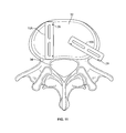
- FIG. 10 illustrates implantation of a first spinal implant in accordance with the present invention within the disc space of adjacent vertebrae, resting on endplate;
- FIG. 12 illustrates the second spinal implant in accordance with the present invention further being moved into close proximity with the first spinal implant
- Certain embodiments of the present invention may be comprised of a high-performance engineering thermoplastic such as polyetherether-ketone (PEEK) or other polymers such as polyvinyl chloride (PVC), polyethylene, polyesters of various sorts, polycarbonate, Teflon coated metal or ultra high molecular weight polyethylene (UHMWPE).
- PEEK polyetherether-ketone
- PVC polyvinyl chloride
- UHMWPE ultra high molecular weight polyethylene
- Certain embodiments of the present invention may be comprised of urethane dimethacrylate (DUDMA)/tri-ethylene glycol dimethacrylate (TEDGMA) blended resin and a plurality of fillers and fibers including bioactive fillers and E-glass fibers.
- Durable materials may also consist of any number of pure metals, metal alloys, or both. Titanium and its alloys are generally used due to their strength and biocompatibility.
- the body 12 of the spinal implant 10 contains one or more magnets 26 imbedded into the implant.
- the magnets 26 may be arranged to be an integral part of the outer surface of the top surface 14 , the bottom surface 16 , the opposing lateral sides 18 and 20 , and the opposing anterior 22 and posterior 24 portions, or combinations thereof.
- magnets 26 are located at opposing ends of the anterior ( FIG. 1 ) and posterior portion 24 ( FIG. 2 ).
- FIG. 4 illustrates an alternative embodiment of the spinal implant 10 which contains a pair of magnets 26 located at one end of the anterior portion 22 and a pair of magnets along the opposing ends of the anterior portion 22 .
- individual magnets 26 are replaced by a magnetic bar 28 .
- the spinal implant holding area 58 is sized and shaped to receive and hold at least one spinal implant 10 .
- the spinal implant holder and insertion device 46 is designed to allow for at least one of the prongs 54 or 56 , to separate from the other to allow for insertion or removal from the spinal implant holding area 58 .
- both prong 54 and 56 can be adapted to move and separate from each other.
- the proximal end 48 may contain an actuating button 53 adapted to provide separation and/or closure of prongs 54 and 56 .
- Spinal implants 10 may contain grooves or channels 60 sized and shaped to receive at least a portion of prongs 54 and 56 , thereby securing the spinal implant within the spinal implant holding area 58 .
- the implant devices can be adapted to be used in other surgical settings, such as orthopedic implants for orthopedic surgeries.
Abstract
Description
Claims (8)
Priority Applications (1)
| Application Number | Priority Date | Filing Date | Title |
|---|---|---|---|
| US14/216,509 US9795492B1 (en) | 2012-04-30 | 2014-03-17 | Magnetically connectable interbody spinal implant devices |
Applications Claiming Priority (4)
| Application Number | Priority Date | Filing Date | Title |
|---|---|---|---|
| US201261640378P | 2012-04-30 | 2012-04-30 | |
| US201361788147P | 2013-03-15 | 2013-03-15 | |
| US13/874,274 US9770341B1 (en) | 2012-04-30 | 2013-04-30 | Magnetic spinal implant |
| US14/216,509 US9795492B1 (en) | 2012-04-30 | 2014-03-17 | Magnetically connectable interbody spinal implant devices |
Related Parent Applications (1)
| Application Number | Title | Priority Date | Filing Date |
|---|---|---|---|
| US13/874,274 Continuation-In-Part US9770341B1 (en) | 2012-04-30 | 2013-04-30 | Magnetic spinal implant |
Publications (1)
| Publication Number | Publication Date |
|---|---|
| US9795492B1 true US9795492B1 (en) | 2017-10-24 |
Family
ID=60082579
Family Applications (1)
| Application Number | Title | Priority Date | Filing Date |
|---|---|---|---|
| US14/216,509 Active 2033-11-19 US9795492B1 (en) | 2012-04-30 | 2014-03-17 | Magnetically connectable interbody spinal implant devices |
Country Status (1)
| Country | Link |
|---|---|
| US (1) | US9795492B1 (en) |
Cited By (1)
| Publication number | Priority date | Publication date | Assignee | Title |
|---|---|---|---|---|
| US11278422B2 (en) * | 2017-07-19 | 2022-03-22 | Vasudeva Rao Rajakumar Deshpande | Intervertebral spinal cage implant and method of assembling the same |
Citations (19)
| Publication number | Priority date | Publication date | Assignee | Title |
|---|---|---|---|---|
| US4349921A (en) * | 1980-06-13 | 1982-09-21 | Kuntz J David | Intervertebral disc prosthesis |
| US5192327A (en) * | 1991-03-22 | 1993-03-09 | Brantigan John W | Surgical prosthetic implant for vertebrae |
| US5522899A (en) * | 1988-06-28 | 1996-06-04 | Sofamor Danek Properties, Inc. | Artificial spinal fusion implants |
| US5861041A (en) * | 1997-04-07 | 1999-01-19 | Arthit Sitiso | Intervertebral disk prosthesis and method of making the same |
| US6110210A (en) * | 1999-04-08 | 2000-08-29 | Raymedica, Inc. | Prosthetic spinal disc nucleus having selectively coupled bodies |
| US6350283B1 (en) * | 2000-04-19 | 2002-02-26 | Gary K. Michelson | Bone hemi-lumbar interbody spinal implant having an asymmetrical leading end and method of installation thereof |
| US20020183761A1 (en) * | 2001-03-08 | 2002-12-05 | Wes Johnson | Tissue distraction device |
| US20040093085A1 (en) * | 2000-04-19 | 2004-05-13 | Michelson Gary K. | Method for installation of artificial hemi-lumbar interbody spinal fusion implant having an asymmetrical leading end |
| US20060015184A1 (en) * | 2004-01-30 | 2006-01-19 | John Winterbottom | Stacking implants for spinal fusion |
| US20060189999A1 (en) * | 2005-02-24 | 2006-08-24 | Paul Zwirkoski | Linked slideable and interlockable rotatable components |
| US20080119853A1 (en) * | 2006-11-21 | 2008-05-22 | Jeffrey Felt | Methods and apparatus for minimally invasive modular interbody fusion devices |
| US20080133017A1 (en) * | 2004-11-15 | 2008-06-05 | Disc-O- Tech Medical Technology | Assembled Prosthesis Such as a Disc |
| US20080249622A1 (en) * | 2007-04-05 | 2008-10-09 | Gray Wayne P | Interbody implant |
| US20080312743A1 (en) * | 2007-06-15 | 2008-12-18 | Thierry Vila | Nucleus Prostheses |
| US20090138086A1 (en) * | 2007-11-27 | 2009-05-28 | Warsaw Orthopedic, Inc. | Stackable Intervertebral Devices and Methods of Use |
| US7591853B2 (en) * | 2005-03-09 | 2009-09-22 | Vertebral Technologies, Inc. | Rail-based modular disc nucleus prosthesis |
| US20110257749A1 (en) * | 2010-04-18 | 2011-10-20 | Fleischmann David T | Intervertebral implants having hydromagnetic joints |
| US8137403B2 (en) * | 2001-04-02 | 2012-03-20 | Warsaw Orthopedic, Inc. | Hemi-interbody spinal fusion implants manufactured from a major long bone ring |
| US20130018467A1 (en) * | 2011-07-15 | 2013-01-17 | Sean Suh | Systems and Methods For Vertebral Body and Disc Height Restoration |
-
2014
- 2014-03-17 US US14/216,509 patent/US9795492B1/en active Active
Patent Citations (19)
| Publication number | Priority date | Publication date | Assignee | Title |
|---|---|---|---|---|
| US4349921A (en) * | 1980-06-13 | 1982-09-21 | Kuntz J David | Intervertebral disc prosthesis |
| US5522899A (en) * | 1988-06-28 | 1996-06-04 | Sofamor Danek Properties, Inc. | Artificial spinal fusion implants |
| US5192327A (en) * | 1991-03-22 | 1993-03-09 | Brantigan John W | Surgical prosthetic implant for vertebrae |
| US5861041A (en) * | 1997-04-07 | 1999-01-19 | Arthit Sitiso | Intervertebral disk prosthesis and method of making the same |
| US6110210A (en) * | 1999-04-08 | 2000-08-29 | Raymedica, Inc. | Prosthetic spinal disc nucleus having selectively coupled bodies |
| US6350283B1 (en) * | 2000-04-19 | 2002-02-26 | Gary K. Michelson | Bone hemi-lumbar interbody spinal implant having an asymmetrical leading end and method of installation thereof |
| US20040093085A1 (en) * | 2000-04-19 | 2004-05-13 | Michelson Gary K. | Method for installation of artificial hemi-lumbar interbody spinal fusion implant having an asymmetrical leading end |
| US20020183761A1 (en) * | 2001-03-08 | 2002-12-05 | Wes Johnson | Tissue distraction device |
| US8137403B2 (en) * | 2001-04-02 | 2012-03-20 | Warsaw Orthopedic, Inc. | Hemi-interbody spinal fusion implants manufactured from a major long bone ring |
| US20060015184A1 (en) * | 2004-01-30 | 2006-01-19 | John Winterbottom | Stacking implants for spinal fusion |
| US20080133017A1 (en) * | 2004-11-15 | 2008-06-05 | Disc-O- Tech Medical Technology | Assembled Prosthesis Such as a Disc |
| US20060189999A1 (en) * | 2005-02-24 | 2006-08-24 | Paul Zwirkoski | Linked slideable and interlockable rotatable components |
| US7591853B2 (en) * | 2005-03-09 | 2009-09-22 | Vertebral Technologies, Inc. | Rail-based modular disc nucleus prosthesis |
| US20080119853A1 (en) * | 2006-11-21 | 2008-05-22 | Jeffrey Felt | Methods and apparatus for minimally invasive modular interbody fusion devices |
| US20080249622A1 (en) * | 2007-04-05 | 2008-10-09 | Gray Wayne P | Interbody implant |
| US20080312743A1 (en) * | 2007-06-15 | 2008-12-18 | Thierry Vila | Nucleus Prostheses |
| US20090138086A1 (en) * | 2007-11-27 | 2009-05-28 | Warsaw Orthopedic, Inc. | Stackable Intervertebral Devices and Methods of Use |
| US20110257749A1 (en) * | 2010-04-18 | 2011-10-20 | Fleischmann David T | Intervertebral implants having hydromagnetic joints |
| US20130018467A1 (en) * | 2011-07-15 | 2013-01-17 | Sean Suh | Systems and Methods For Vertebral Body and Disc Height Restoration |
Cited By (1)
| Publication number | Priority date | Publication date | Assignee | Title |
|---|---|---|---|---|
| US11278422B2 (en) * | 2017-07-19 | 2022-03-22 | Vasudeva Rao Rajakumar Deshpande | Intervertebral spinal cage implant and method of assembling the same |
Similar Documents
| Publication | Publication Date | Title |
|---|---|---|
| US11896493B2 (en) | Expandable intervertebral spacer | |
| US11759331B2 (en) | Stabilized expandable intervertebral spacer | |
| US20210128314A1 (en) | Spinal Surgical Implant and Related Methods | |
| US20180221166A1 (en) | Coiled Implants And Systems And Methods Of Use Thereof | |
| US8597356B2 (en) | Intervertebral implant | |
| US20170165082A1 (en) | Stabilized expandable intervertebral spacer | |
| US11259938B2 (en) | Stabilized intervertebral spacer | |
| EP1161205A1 (en) | Method and apparatus for intervertebral implant anchorage | |
| US9241810B1 (en) | Fusion device and associated methods | |
| US9770341B1 (en) | Magnetic spinal implant | |
| US9795492B1 (en) | Magnetically connectable interbody spinal implant devices | |
| US11850161B2 (en) | Expanding intervertebral implants | |
| EP2635213B1 (en) | Stabilizers, end cap and connector for assisting stabilization of a spinal implant | |
| US11759328B2 (en) | Expandable motion preservation spacer | |
| US20200054455A1 (en) | Interbody standalone device with integrated fixations |
Legal Events
| Date | Code | Title | Description |
|---|---|---|---|
| AS | Assignment |
Owner name: NUVASIVE, INC., CALIFORNIA Free format text: ASSIGNMENT OF ASSIGNORS INTEREST;ASSIGNOR:WALSH, CHRISTOPHER;REEL/FRAME:033071/0092 Effective date: 20140606 |
|
| AS | Assignment |
Owner name: BANK OF AMERICA, N.A., AS ADMINISTRATIVE AGENT, CALIFORNIA Free format text: NOTICE OF GRANT OF SECURITY INTEREST IN PATENTS;ASSIGNORS:NUVASIVE, INC.;IMPULSE MONITORING, INC.;REEL/FRAME:040634/0404 Effective date: 20160208 Owner name: BANK OF AMERICA, N.A., AS ADMINISTRATIVE AGENT, CA Free format text: NOTICE OF GRANT OF SECURITY INTEREST IN PATENTS;ASSIGNORS:NUVASIVE, INC.;IMPULSE MONITORING, INC.;REEL/FRAME:040634/0404 Effective date: 20160208 |
|
| AS | Assignment |
Owner name: BANK OF AMERICA, N.A., AS ADMINISTRATIVE AGENT, TEXAS Free format text: NOTICE OF GRANT OF SECURITY INTEREST IN PATENTS;ASSIGNORS:NUVASIVE, INC.;BIOTRONIC NATIONAL, LLC;NUVASIVE CLINICAL SERVICES MONITORING, INC.;AND OTHERS;REEL/FRAME:042490/0236 Effective date: 20170425 Owner name: BANK OF AMERICA, N.A., AS ADMINISTRATIVE AGENT, TE Free format text: NOTICE OF GRANT OF SECURITY INTEREST IN PATENTS;ASSIGNORS:NUVASIVE, INC.;BIOTRONIC NATIONAL, LLC;NUVASIVE CLINICAL SERVICES MONITORING, INC.;AND OTHERS;REEL/FRAME:042490/0236 Effective date: 20170425 |
|
| STCF | Information on status: patent grant |
Free format text: PATENTED CASE |
|
| AS | Assignment |
Owner name: BANK OF AMERICA, N.A., AS ADMINISTRATIVE AGENT, NORTH CAROLINA Free format text: SECURITY INTEREST;ASSIGNORS:NUVASIVE, INC.;NUVASIVE CLINICAL SERVICES MONITORING, INC.;NUVASIVE CLINICAL SERVICES, INC.;AND OTHERS;REEL/FRAME:052918/0595 Effective date: 20200224 |
|
| MAFP | Maintenance fee payment |
Free format text: PAYMENT OF MAINTENANCE FEE, 4TH YEAR, LARGE ENTITY (ORIGINAL EVENT CODE: M1551); ENTITY STATUS OF PATENT OWNER: LARGE ENTITY Year of fee payment: 4 |