US9797054B2 - Pressure driven ceramic oxygen generation system with integrated manifold and tubes - Google Patents
Pressure driven ceramic oxygen generation system with integrated manifold and tubes Download PDFInfo
- Publication number
- US9797054B2 US9797054B2 US14/326,934 US201414326934A US9797054B2 US 9797054 B2 US9797054 B2 US 9797054B2 US 201414326934 A US201414326934 A US 201414326934A US 9797054 B2 US9797054 B2 US 9797054B2
- Authority
- US
- United States
- Prior art keywords
- support member
- oxygen
- tubes
- tube support
- mixed conducting
- Prior art date
- Legal status (The legal status is an assumption and is not a legal conclusion. Google has not performed a legal analysis and makes no representation as to the accuracy of the status listed.)
- Active, expires
Links
- 239000000919 ceramic Substances 0.000 title claims abstract description 62
- 239000001301 oxygen Substances 0.000 title claims description 72
- 229910052760 oxygen Inorganic materials 0.000 title claims description 72
- QVGXLLKOCUKJST-UHFFFAOYSA-N atomic oxygen Chemical compound [O] QVGXLLKOCUKJST-UHFFFAOYSA-N 0.000 title claims description 62
- 239000000463 material Substances 0.000 claims abstract description 35
- 239000000203 mixture Substances 0.000 claims abstract description 28
- 239000002131 composite material Substances 0.000 claims abstract description 15
- 229910052723 transition metal Inorganic materials 0.000 claims abstract description 14
- 150000003624 transition metals Chemical class 0.000 claims abstract description 14
- 229910052747 lanthanoid Inorganic materials 0.000 claims abstract description 9
- 150000002602 lanthanoids Chemical class 0.000 claims abstract description 9
- 230000007935 neutral effect Effects 0.000 claims abstract description 9
- 239000000126 substance Substances 0.000 claims abstract description 8
- 239000011532 electronic conductor Substances 0.000 claims abstract description 7
- 239000010416 ion conductor Substances 0.000 claims abstract description 7
- 229910002714 Ba0.5Sr0.5 Inorganic materials 0.000 claims description 8
- 229910002505 Co0.8Fe0.2 Inorganic materials 0.000 claims description 4
- 238000004891 communication Methods 0.000 claims description 3
- 239000012528 membrane Substances 0.000 description 28
- -1 oxygen ions Chemical class 0.000 description 10
- 239000007789 gas Substances 0.000 description 9
- 229910010293 ceramic material Inorganic materials 0.000 description 8
- 238000013461 design Methods 0.000 description 8
- 238000000576 coating method Methods 0.000 description 5
- MYMOFIZGZYHOMD-UHFFFAOYSA-N Dioxygen Chemical compound O=O MYMOFIZGZYHOMD-UHFFFAOYSA-N 0.000 description 4
- 229910001882 dioxygen Inorganic materials 0.000 description 4
- 150000002500 ions Chemical class 0.000 description 3
- XKRFYHLGVUSROY-UHFFFAOYSA-N Argon Chemical compound [Ar] XKRFYHLGVUSROY-UHFFFAOYSA-N 0.000 description 2
- IJGRMHOSHXDMSA-UHFFFAOYSA-N Atomic nitrogen Chemical compound N#N IJGRMHOSHXDMSA-UHFFFAOYSA-N 0.000 description 2
- MCMNRKCIXSYSNV-UHFFFAOYSA-N Zirconium dioxide Chemical compound O=[Zr]=O MCMNRKCIXSYSNV-UHFFFAOYSA-N 0.000 description 2
- 238000013459 approach Methods 0.000 description 2
- 229910044991 metal oxide Inorganic materials 0.000 description 2
- 238000000034 method Methods 0.000 description 2
- 239000011533 mixed conductor Substances 0.000 description 2
- 239000007787 solid Substances 0.000 description 2
- 238000003860 storage Methods 0.000 description 2
- 235000006679 Mentha X verticillata Nutrition 0.000 description 1
- 235000002899 Mentha suaveolens Nutrition 0.000 description 1
- 235000001636 Mentha x rotundifolia Nutrition 0.000 description 1
- 229910052786 argon Inorganic materials 0.000 description 1
- 230000000712 assembly Effects 0.000 description 1
- 238000000429 assembly Methods 0.000 description 1
- 229910021525 ceramic electrolyte Inorganic materials 0.000 description 1
- CETPSERCERDGAM-UHFFFAOYSA-N ceric oxide Chemical compound O=[Ce]=O CETPSERCERDGAM-UHFFFAOYSA-N 0.000 description 1
- 229910000422 cerium(IV) oxide Inorganic materials 0.000 description 1
- 238000012993 chemical processing Methods 0.000 description 1
- 239000011248 coating agent Substances 0.000 description 1
- 239000004020 conductor Substances 0.000 description 1
- 239000000470 constituent Substances 0.000 description 1
- 230000003247 decreasing effect Effects 0.000 description 1
- 238000010586 diagram Methods 0.000 description 1
- 238000005868 electrolysis reaction Methods 0.000 description 1
- 238000010438 heat treatment Methods 0.000 description 1
- 238000002347 injection Methods 0.000 description 1
- 239000007924 injection Substances 0.000 description 1
- 238000001746 injection moulding Methods 0.000 description 1
- 238000007726 management method Methods 0.000 description 1
- 238000004519 manufacturing process Methods 0.000 description 1
- 150000004706 metal oxides Chemical class 0.000 description 1
- 238000013508 migration Methods 0.000 description 1
- 230000005012 migration Effects 0.000 description 1
- 229910052757 nitrogen Inorganic materials 0.000 description 1
- 229920005597 polymer membrane Polymers 0.000 description 1
- ZRHANBBTXQZFSP-UHFFFAOYSA-M potassium;4-amino-3,5,6-trichloropyridine-2-carboxylate Chemical compound [K+].NC1=C(Cl)C(Cl)=NC(C([O-])=O)=C1Cl ZRHANBBTXQZFSP-UHFFFAOYSA-M 0.000 description 1
- 238000012545 processing Methods 0.000 description 1
- 238000003908 quality control method Methods 0.000 description 1
- 238000000926 separation method Methods 0.000 description 1
- 238000001179 sorption measurement Methods 0.000 description 1
- 238000009827 uniform distribution Methods 0.000 description 1
Images


Classifications
-
- C—CHEMISTRY; METALLURGY
- C25—ELECTROLYTIC OR ELECTROPHORETIC PROCESSES; APPARATUS THEREFOR
- C25B—ELECTROLYTIC OR ELECTROPHORETIC PROCESSES FOR THE PRODUCTION OF COMPOUNDS OR NON-METALS; APPARATUS THEREFOR
- C25B13/00—Diaphragms; Spacing elements
- C25B13/04—Diaphragms; Spacing elements characterised by the material
-
- B—PERFORMING OPERATIONS; TRANSPORTING
- B01—PHYSICAL OR CHEMICAL PROCESSES OR APPARATUS IN GENERAL
- B01D—SEPARATION
- B01D53/00—Separation of gases or vapours; Recovering vapours of volatile solvents from gases; Chemical or biological purification of waste gases, e.g. engine exhaust gases, smoke, fumes, flue gases, aerosols
- B01D53/22—Separation of gases or vapours; Recovering vapours of volatile solvents from gases; Chemical or biological purification of waste gases, e.g. engine exhaust gases, smoke, fumes, flue gases, aerosols by diffusion
- B01D53/228—Separation of gases or vapours; Recovering vapours of volatile solvents from gases; Chemical or biological purification of waste gases, e.g. engine exhaust gases, smoke, fumes, flue gases, aerosols by diffusion characterised by specific membranes
-
- B—PERFORMING OPERATIONS; TRANSPORTING
- B01—PHYSICAL OR CHEMICAL PROCESSES OR APPARATUS IN GENERAL
- B01D—SEPARATION
- B01D63/00—Apparatus in general for separation processes using semi-permeable membranes
- B01D63/06—Tubular membrane modules
-
- C—CHEMISTRY; METALLURGY
- C01—INORGANIC CHEMISTRY
- C01B—NON-METALLIC ELEMENTS; COMPOUNDS THEREOF; METALLOIDS OR COMPOUNDS THEREOF NOT COVERED BY SUBCLASS C01C
- C01B13/00—Oxygen; Ozone; Oxides or hydroxides in general
- C01B13/02—Preparation of oxygen
- C01B13/0229—Purification or separation processes
- C01B13/0248—Physical processing only
- C01B13/0251—Physical processing only by making use of membranes
- C01B13/0255—Physical processing only by making use of membranes characterised by the type of membrane
-
- C—CHEMISTRY; METALLURGY
- C25—ELECTROLYTIC OR ELECTROPHORETIC PROCESSES; APPARATUS THEREFOR
- C25B—ELECTROLYTIC OR ELECTROPHORETIC PROCESSES FOR THE PRODUCTION OF COMPOUNDS OR NON-METALS; APPARATUS THEREFOR
- C25B1/00—Electrolytic production of inorganic compounds or non-metals
- C25B1/01—Products
- C25B1/02—Hydrogen or oxygen
-
- H—ELECTRICITY
- H01—ELECTRIC ELEMENTS
- H01B—CABLES; CONDUCTORS; INSULATORS; SELECTION OF MATERIALS FOR THEIR CONDUCTIVE, INSULATING OR DIELECTRIC PROPERTIES
- H01B1/00—Conductors or conductive bodies characterised by the conductive materials; Selection of materials as conductors
- H01B1/06—Conductors or conductive bodies characterised by the conductive materials; Selection of materials as conductors mainly consisting of other non-metallic substances
- H01B1/08—Conductors or conductive bodies characterised by the conductive materials; Selection of materials as conductors mainly consisting of other non-metallic substances oxides
-
- B—PERFORMING OPERATIONS; TRANSPORTING
- B01—PHYSICAL OR CHEMICAL PROCESSES OR APPARATUS IN GENERAL
- B01D—SEPARATION
- B01D53/00—Separation of gases or vapours; Recovering vapours of volatile solvents from gases; Chemical or biological purification of waste gases, e.g. engine exhaust gases, smoke, fumes, flue gases, aerosols
- B01D53/22—Separation of gases or vapours; Recovering vapours of volatile solvents from gases; Chemical or biological purification of waste gases, e.g. engine exhaust gases, smoke, fumes, flue gases, aerosols by diffusion
- B01D2053/221—Devices
- B01D2053/223—Devices with hollow tubes
Definitions
- the present invention relates to devices for separating oxygen from a more complex gas containing oxygen to deliver the separated oxygen for use, and more particularly, the invention relates to solid state electrochemical devices for separating oxygen from a more complex gas, and even more particularly to a pressure driven ceramic oxygen generating system with integrated manifold and tubes.
- COGS Ceramic Oxygen Generating Systems
- the present invention takes advantage of the phenomenon that, when raised to sufficient temperature (over 600° C.), certain ceramic materials can easily have oxygen ions dislodged from within the ceramic's lattice structure. That is, when these materials are formed into a thin membrane, a driving force and a fresh oxygen supply on one side of the membrane induce a flow of oxygen through the membrane. Since the oxygen ions that migrate through the membrane are actually elemental constituents of the ceramic lattice, only oxygen can flow through the membrane. Other gaseous species, such as nitrogen or argon, cannot migrate through the lattice as these species are incompatible with the ceramic lattice structure. As a result, the derived concentrated product gas stream contains high purity oxygen gas.
- Oxygen flow across a ceramic membrane is commonly induced through two methods: electrically driven or pressure driven.
- an electric potential is induced across the ceramic membrane using special coatings and a voltage supply.
- the oxygen ions present within the ceramic when at high temperature (over 600° C.) are driven through the membrane by the voltage difference between opposing surfaces of the membrane. Since the oxygen ions are charged species, the number of ions migrating through the membrane is directly related to the magnitude of the electrical current passing through the membrane where higher currents result in more ion migration.
- the ceramic is comprised of a mixed conductor composition which can conduct both oxygen ions and electrons.
- An inlet compressed air source and/or a vacuum outlet at the product side generate a pressure differential across the ceramic membrane.
- the ceramic membrane ionizes oxygen molecules on the membrane surface exposed to gases with higher oxygen partial pressure. Oxygen ions then diffuse across the ceramic membrane and recombine into oxygen molecules at the opposite surface which has lower oxygen partial pressure.
- only oxygen ions are compatible with the ceramic lattice such that only oxygen gas is generated at the product outlet, thereby producing an extremely high purity oxygen gas product.
- IMAT Integrated Manifold and Tubes
- any surface area other than that coated by the conductive coating is unavailable for generating oxygen, thus leading to decreased utilization potential of the ceramic membrane materials.
- the size and thickness of each tube within the array needs to be closely matched (if not exactly the same) so that there would be relatively uniform distribution of voltages for the components connected in serial relation. This requires tight design tolerances and vigilant quality control.
- self-heating of the ceramic is significant and requires careful thermal management to optimize oxygen production without damaging or destroying the IMAT module.
- Another object of this invention is to provide a ceramic oxygen generator for a pressure driven COGS system wherein the ceramic material comprises a mixed conducting material.
- a further object of this invention is to provide a ceramic oxygen generator for a pressure driven COGS system wherein a manifold structure for receiving the separated oxygen is an integral part of the manufactured generator structure and is less costly to make.
- Still another object or this invention is to provide a ceramic oxygen generator for a pressure driven COGS system which is of a modular configuration and thereby provides a simple “building block” approach to meet differing requirements for amounts of oxygen to be generated.
- the present invention addresses the above needs by providing a solid state electrochemical device for separating oxygen from a more complex gas.
- the oxygen separation device utilizes a class of ceramic materials which can simultaneously conduct ionic species (i.e., oxygen ions and oxygen vacancies) and electronic species (i.e., electrons and holes)—commonly referred to as a mixed conducting membrane.
- the ceramic material is generally comprised of a metallic oxide composition and may have the general chemical composition of A x A′ x′ A′′ x′′ B y B′ y′ B′′ y′′ O 3-z , where A, A′, and A′′ are selected from Group II elements or the Lanthanoids, and B, B′, B′′ are selected from the d-block transition metals, and more particularly the d-block transition metals of Period 4, wherein 0 ⁇ x ⁇ 1, 0 ⁇ x′ ⁇ 1, 0 ⁇ x′′ ⁇ 1, 0 ⁇ y ⁇ 1, 0 ⁇ y′ ⁇ 1, 0 ⁇ y′′ ⁇ 1, x+x′+x′′ ⁇ 1, y+y′+y′′ ⁇ 1, and z is selected so that the resultant composition is charge neutral.
- the ceramic membrane material can also be a composite consisting of two or more component materials, of which one component is predominantly an electronic conductor and another is predominantly an ionic conductor. Further, the ceramic membrane material may also be a composite material containing at least one component material with a general chemical composition of A x A′ x′ A′′ x ′′B y B′ y′ B′′ y′′ O 3-z .
- a mixed conducting ceramic element comprises a plurality of tubes each having interior and exterior surfaces, and each having a closed end and an open end.
- a tube support member receives the open ends of the plurality of tubes.
- the ceramic element has a general composition o f A x A′ x′ A′′ x′′ B y B′ y′ B′′ y′′ O 3-z , where A, A′, and A′′ are selected from Group II elements or the Lanthanoids, and B, B′, B′′ are selected from the d-block transition metals, and wherein 0 ⁇ x ⁇ 1, 0 ⁇ x′ ⁇ 1, 0 ⁇ x′′ ⁇ 1, 0 ⁇ y ⁇ 1, 0 ⁇ y′ ⁇ 1, 0 ⁇ y′′ ⁇ 1, x+x′+x′′ ⁇ 1, y+y′+y′′ ⁇ 1, and z is selected so that the resultant composition is charge neutral.
- the d-block transition metals may be selected from the d-block transition metals of Period 4.
- the ceramic material is comprised of a composition selected from the list consisting of BaTi 0.2 Co 0.4 Fe 0.4 O 3-z , BaTi 0.2 Co 0.5 Fe 0.3 O 3-z , Ba 0.5 Sr 0.5 Zn 0.2 Fe 0.8 O 3-z , Ba 0.5 Sr 0.5 Co 0.8 Fe 0.3 O 3-z , SrCo 0.8 Fe 0.2 O 3-z and La 0.6 Ba 0.4 Co 0.8 Fe 0.2 O 3-z .
- the ceramic membrane material can also be a composite consisting of two or more component materials, of which one component is predominantly an electronic conductor and another is predominantly an ionic conductor. Further, the ceramic membrane material may also be a composite material containing at least one component material with a general chemical composition of A x A′ x′ A′′ x′′ B y B′ y′ B′′ y′′ O 3-z .
- an oxygen generator comprises a first mixed conducting ceramic element having a first tube support member and a first array of tube members extending from the first tube support member and formed into columns and rows.
- a second mixed conducting ceramic element has a second tube support member and a second array of tube members extending from the second tube support member and formed into columns and rows.
- a seal is formed between the first tube support member of the first mixed conducting ceramic element and the second tube support member of the second mixed conducting ceramic element so as to define a manifold having and open interior space therebetween.
- the first mixed conducting ceramic element and the second mixed conducting ceramic element may comprise a composition of A x A′ x′ A′′ x′′ B y B′ y′ B′′ y′′ O 3-z , where A, A′, and A′′ are selected from Group II elements or the Lanthanoids, and B, B′, B′′ are selected from the d-block transition metals, and wherein 0 ⁇ x ⁇ 1, 0 ⁇ x′ ⁇ 1, 0 ⁇ x′′ ⁇ 1, 0 ⁇ y ⁇ 1, 0 ⁇ y′ ⁇ 1, 0 ⁇ y′′ ⁇ 1, x+x′+x′′ ⁇ 1, y+y′+y′′ ⁇ 1, and z is selected so that the resultant composition is charge neutral.
- the ceramic membrane material can also be a composite consisting of two or more component materials, of which one component is predominantly an electronic conductor and another is predominantly an ionic conductor. Further, the ceramic membrane material may also be a composite material containing at least one component material with a general chemical composition of A x A′ x′ A′′ x′′ B y B′ y′ B′′ y′′ O 3-z . Each respective tube support member and array of tube members of each of the first mixed conducting ceramic element and the second mixed conducting ceramic element is integrally formed.
- the oxygen generator may further include an outlet port in communication with the interior space of the manifold.
- FIG. 1 is a top perspective view of one of the molded, modular elements used to form a module assembly of two molded elements creating the mixed conducting ceramic oxygen generator module assembly according to the invention.
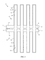
- FIG. 3 is a partial cross sectional vie v taken along the line 3 - 3 of FIG. 1 .
- FIG. 4 is a block schematic diagram of a pressure driven mixed conducting ceramic oxygen generating system with integrated manifold and tubes in accordance with the invention.
- the mixed conducting ceramic oxygen generating assembly is generally comprised of modular elements 10 .
- Modular element 10 can be, for example, injection molded of a mixed conducting ceramic electrolyte, and preferably has the composition A x A′ x A′′ x′′ B y B′ y′ B′′ y′′ O 3-z , where A, A′, and A′′ are selected from Group II elements or the Lanthanoids, and B, B′, B′′ are selected from the d-block transition metals, and wherein 0 ⁇ x ⁇ 1, 0 ⁇ x′ ⁇ 1, 0 ⁇ x′′ ⁇ 1, 0 ⁇ y ⁇ 1, 0 ⁇ y′ ⁇ 1, 0 ⁇ y′′ ⁇ 1, x+x′+x′′ ⁇ 1, y+y′+y′′ ⁇ 1, and z is selected so that the resultant composition is charge neutral.
- suitable mixed conducting ceramic materials include, but are not necessarily limited solely thereto, BaTi 0.2 Co 0.4 Fe 0.4 O 3-z , BaTi 0.2 Co 0.5 Fe 0.3 O 3-z , Ba 0.5 Sr 0.5 Zn 0.2 Fe 0.8 O 3-z , Ba 0.5 Sr 0.5 Co 0.8 Fe 0.3 O 3-z , SrCo 0.8 Fe 0.2 O 3-z and La 0.6 Ba 0.4 Co 0.8 Fe 0.2 O 3-z .
- the ceramic membrane material can also be a composite consisting of two or more component materials, of which one component is predominantly an electronic conductor and another is predominantly an ionic conductor.
- the ceramic membrane material may also be a composite material containing at least one component material with a general chemical composition of A x A′ x′ A′′ x′′ B y B′ y′ B′′ y′′ O 3-z .
- Modular element 10 is generally constructed as an integrated Manifold and Tithes (IMAT) module design thereby providing a large surface area per unit volume.
- the IMAT design also includes an integral manifold structure (described below) for collecting oxygen.
- the injection molding process used to generate modular element 10 permits the mixed conductive ceramic material to be formed into a series of tubes 12 extending from a top surface 16 of a generally planar tube support member 14 .
- tube support member 14 is shown and described as generally planar, it is envisioned that the tube support member may be constructed to include any desired shape, provided that two opposing base surfaces can be sealed together to form the integral manifold structure (described below).
- the tubes may be formed to include any number of rows and columns of tubes in an array, where such number of tubes may be dictated by the overall size of the generator or the envisioned maximum oxygen demand placed upon the system.
- the tubes 12 may be formed into twenty-eight columns of eight tubes each, or stated another way, eight rows of twenty-eight tubes each. The distal end of each tube 12 is closed at cap end 15 .
- the symmetry of the modular design of element 10 allows a second element 10 ′ to be inverted and sealed to the first element to form an assembly 11 .
- a flange member 22 extends outwardly from the lower surface 18 of tube support member 14 around the perimeter thereof so that when the elements 10 and 10 ′ are placed together as in FIG. 2 , the flange members 22 and 22 ′ are joined to form a manifold with an interior space 24 between the lower surfaces 18 / 18 ′ of the two elements 10 and 10 ′.
- An exit port 26 is defined by the union of tube support members 14 / 14 ′ and communicates with the interior space 24 of the manifold. While shown along one end, one or more outlet ports could also exit along each end or along the longer edges of the elements 10 and 10 ′ so as to allow serial connection of multiple assemblies 11 in end-to-end or side-by-side connections as desired or dictated by system demands.
- one or more IMAT modules 11 may be situated within an oven 42 .
- the IMAT modules are sufficiently heated (i.e. over 600° C., within oven 42 ) to cause ionization of oxygen molecules on the ceramic membrane surface and sufficient conductivity of oxygen ions within the ceramic lattice material.
- Air or other gas from which oxygen is to be extracted enters the oven and flows across the tubes 12 .
- a pressure differential is created between the external surface of 12 a / 12 a ′ and internal surface 12 b / 12 b ′ of each tube 12 / 12 ′. This pressure differential may be created by introducing compressed gas into the oven through compressed air source 44 and/or by generating a negative pressure within interior space 24 and tube interiors 12 c / 12 c ′ by way of a vacuum pump 46 .
- this pressure differential drives oxygen ions through the mixed conductive ceramic membrane material such that the ions reform oxygen gas in the interiors 12 c / 12 c ′ of tubes 12 / 12 ′, with the gas being collected in interior space 24 of the manifold.
- This supply of oxygen is communicated via port 26 to a component having the oxygen requirement or storage (such as through vacuum pump 46 ).
- a component having the oxygen requirement or storage such as through vacuum pump 46 .
- the gas pressure may be reduced to atmospheric pressure for eventual delivery to a cannula or gasmask.
- oxygen may also be delivered to an oxygen compressor 48 for pressurization of oxygen storage cylinders for later use.
- a control unit 50 may be in operational communication with each of the oven 42 , compressed air source 44 , vacuum pump 46 and/or oxygen compressor 48 .
Abstract
Description
Claims (13)
Priority Applications (1)
| Application Number | Priority Date | Filing Date | Title |
|---|---|---|---|
| US14/326,934 US9797054B2 (en) | 2014-07-09 | 2014-07-09 | Pressure driven ceramic oxygen generation system with integrated manifold and tubes |
Applications Claiming Priority (1)
| Application Number | Priority Date | Filing Date | Title |
|---|---|---|---|
| US14/326,934 US9797054B2 (en) | 2014-07-09 | 2014-07-09 | Pressure driven ceramic oxygen generation system with integrated manifold and tubes |
Publications (2)
| Publication Number | Publication Date |
|---|---|
| US20160010230A1 US20160010230A1 (en) | 2016-01-14 |
| US9797054B2 true US9797054B2 (en) | 2017-10-24 |
Family
ID=55067143
Family Applications (1)
| Application Number | Title | Priority Date | Filing Date |
|---|---|---|---|
| US14/326,934 Active 2034-10-14 US9797054B2 (en) | 2014-07-09 | 2014-07-09 | Pressure driven ceramic oxygen generation system with integrated manifold and tubes |
Country Status (1)
| Country | Link |
|---|---|
| US (1) | US9797054B2 (en) |
Citations (46)
| Publication number | Priority date | Publication date | Assignee | Title |
|---|---|---|---|---|
| US4508548A (en) | 1981-08-04 | 1985-04-02 | The Garrett Corporation | Air oxygen and nitrogen concentration device |
| US5108465A (en) | 1989-06-29 | 1992-04-28 | Merck Patent Gesellschaft Mit Beschrankter Haftung | Process and device for obtaining pure oxygen |
| US5131225A (en) | 1990-08-31 | 1992-07-21 | Sundstrand Corporation | Apparatus for separating and compressing oxygen from an air stream |
| US5155158A (en) | 1989-11-07 | 1992-10-13 | Hoechst Celanese Corp. | Moldable ceramic compositions |
| US5169415A (en) | 1990-08-31 | 1992-12-08 | Sundstrand Corporation | Method of generating oxygen from an air stream |
| GB2257054A (en) | 1991-07-04 | 1993-01-06 | Normalair Garrett | Oxygen generating system |
| US5186793A (en) | 1990-12-31 | 1993-02-16 | Invacare Corporation | Oxygen concentrator utilizing electrochemical cell |
| US5766317A (en) | 1995-06-01 | 1998-06-16 | Technology Management, Inc. | Microspheres for combined oxygen separation, storage and delivery |
| US5871624A (en) | 1995-08-24 | 1999-02-16 | Litton Systems, Inc. | Modular ceramic oxygen generator |
| US5888272A (en) | 1997-06-05 | 1999-03-30 | Praxair Technology, Inc. | Process for enriched combustion using solid electrolyte ionic conductor systems |
| US5910238A (en) | 1995-06-01 | 1999-06-08 | Technology Management, Inc. | Microspheres for combined oxygen separation, storage and delivery |
| US5922178A (en) | 1997-06-25 | 1999-07-13 | Isenberg; Arnold O. | High temperature gas separation apparatus |
| US5985113A (en) | 1995-08-24 | 1999-11-16 | Litton Systems, Inc. | Modular ceramic electrochemical apparatus and method of manufacture therefor |
| US6117210A (en) | 1997-04-29 | 2000-09-12 | Praxair Technology, Inc. | Solid electrolyte systems for producing controlled purity oxygen |
| US6139604A (en) | 1997-11-18 | 2000-10-31 | Praxair Technology, Inc. | Thermally powered oxygen/nitrogen plant incorporating an oxygen selective ion transport membrane |
| US6153163A (en) | 1998-06-03 | 2000-11-28 | Praxair Technology, Inc. | Ceramic membrane reformer |
| US6293084B1 (en) | 2000-05-04 | 2001-09-25 | Praxair Technology, Inc. | Oxygen separator designed to be integrated with a gas turbine and method of separating oxygen |
| US6309612B1 (en) | 1998-11-18 | 2001-10-30 | The United States Of America As Represented By The United States Department Of Energy | Ceramic membrane reactor with two reactant gases at different pressures |
| US6352624B1 (en) | 1999-06-01 | 2002-03-05 | Northrop Grumman Corporation | Electrochemical oxygen generating system |
| US6368491B1 (en) | 2000-11-08 | 2002-04-09 | Northrop Grumman Corporation | Method of controlling a modular ceramic oxygen generating system |
| US6368383B1 (en) | 1999-06-08 | 2002-04-09 | Praxair Technology, Inc. | Method of separating oxygen with the use of composite ceramic membranes |
| US6406518B1 (en) | 2000-08-21 | 2002-06-18 | Praxair Technology, Inc. | Gas separation process using ceramic membrane and regenerators |
| US6592782B2 (en) | 1993-12-08 | 2003-07-15 | Eltron Research, Inc. | Materials and methods for the separation of oxygen from air |
| JP2003218096A (en) | 2002-01-28 | 2003-07-31 | Ulvac Japan Ltd | Vacuum processing system for generating oxygen ion |
| JP2004022202A (en) | 2002-06-12 | 2004-01-22 | Ulvac Japan Ltd | Vacuum treatment device for generating negative charge oxygen ion |
| US6685235B1 (en) | 2000-05-19 | 2004-02-03 | Carleton Life Support Systems, Inc. | System and method for attaching tubing |
| US20040065541A1 (en) | 2002-08-27 | 2004-04-08 | Litton Systems, Inc. | Stepped voltage controller for ceramic oxygen generating systems |
| US6783646B2 (en) | 2002-08-28 | 2004-08-31 | Carleton Life Support Systems, Inc. | Modular ceramic oxygen system |
| US6849296B2 (en) | 2002-07-29 | 2005-02-01 | Carleton Life Support Systems, Inc. | Leakage free ceramic films for porous surfaces |
| US6979511B2 (en) | 1999-07-31 | 2005-12-27 | The Regents Of The University Of California | Structures and fabrication techniques for solid state electrochemical devices |
| US7309847B2 (en) | 2006-01-12 | 2007-12-18 | Carleton Life Support Systems, Inc. | Ceramic oxygen generating oven |
| US7396442B2 (en) | 2005-02-08 | 2008-07-08 | Carleton Life Support Systems, Inc. | Electrochemical oxygen generator module assembly |
| US7442344B2 (en) | 2001-11-09 | 2008-10-28 | Chubu Electric Power Co., Inc. | Ceramic member with oxygen ion conductivity and use thereof |
| US20090272266A1 (en) | 2005-02-11 | 2009-11-05 | Uhde Gmbh | Method for oxygenating gases, systems suited therefor and use thereof |
| US7645365B2 (en) | 2005-02-09 | 2010-01-12 | Carleton Life Support Systems, Inc. | IMAT modules with serial conductive stripes |
| JP2010052980A (en) | 2008-08-28 | 2010-03-11 | Tokyo Institute Of Technology | Oxygen atom generating apparatus |
| US7694674B2 (en) | 2004-09-21 | 2010-04-13 | Carleton Life Support Systems, Inc. | Oxygen generator with storage and conservation modes |
| US20110275866A1 (en) * | 2010-05-06 | 2011-11-10 | Air Products And Chemicals, Inc. | Feed Gas Contaminant Removal in Ion Transport Membrane Systems |
| US8070922B2 (en) | 2006-08-07 | 2011-12-06 | Oxus America, Inc. | Monolithic supported oxygen generator |
| US20120000360A1 (en) | 2010-07-01 | 2012-01-05 | L'air Liquide, Societe Anonyme Pour I'etude Et I'exploitation Des Procedes Georges Claude | Method Of Operating A Mixed Ionic-Electronic Conducting Ceramic Membrane |
| US20120067210A1 (en) * | 2010-09-16 | 2012-03-22 | Volt Research | High temperature gas processing system and method for making the same |
| US20120318145A1 (en) | 2010-03-05 | 2012-12-20 | Koninklijke Philips Electronics N.V. | Oxygen separation membrane |
| US20130032760A1 (en) | 2009-12-29 | 2013-02-07 | Steffen Werth | Device and method for controlling the permeation of oxygen through non-porous ceramic membranes which conduct oxygen anions, and the use thereof |
| US8394178B2 (en) | 2009-07-22 | 2013-03-12 | Vbox, Incorporated | Apparatus for separating oxygen from ambient air |
| US8500872B2 (en) | 2008-01-02 | 2013-08-06 | Technion Research & Development Foundation Ltd. | Ceramic tubes composed of two materials |
| US20130220127A1 (en) | 2011-04-08 | 2013-08-29 | Gervase Maxwell Christie | Oxygen separation module and apparatus |
-
2014
- 2014-07-09 US US14/326,934 patent/US9797054B2/en active Active
Patent Citations (51)
| Publication number | Priority date | Publication date | Assignee | Title |
|---|---|---|---|---|
| US4508548A (en) | 1981-08-04 | 1985-04-02 | The Garrett Corporation | Air oxygen and nitrogen concentration device |
| US5108465A (en) | 1989-06-29 | 1992-04-28 | Merck Patent Gesellschaft Mit Beschrankter Haftung | Process and device for obtaining pure oxygen |
| US5155158A (en) | 1989-11-07 | 1992-10-13 | Hoechst Celanese Corp. | Moldable ceramic compositions |
| US5131225A (en) | 1990-08-31 | 1992-07-21 | Sundstrand Corporation | Apparatus for separating and compressing oxygen from an air stream |
| US5169415A (en) | 1990-08-31 | 1992-12-08 | Sundstrand Corporation | Method of generating oxygen from an air stream |
| US5186793A (en) | 1990-12-31 | 1993-02-16 | Invacare Corporation | Oxygen concentrator utilizing electrochemical cell |
| US5397443A (en) | 1990-12-31 | 1995-03-14 | Invacare Corporation | Method of assembling tubular electrochemical oxygen generators |
| GB2257054A (en) | 1991-07-04 | 1993-01-06 | Normalair Garrett | Oxygen generating system |
| US6592782B2 (en) | 1993-12-08 | 2003-07-15 | Eltron Research, Inc. | Materials and methods for the separation of oxygen from air |
| US5910238A (en) | 1995-06-01 | 1999-06-08 | Technology Management, Inc. | Microspheres for combined oxygen separation, storage and delivery |
| US5766317A (en) | 1995-06-01 | 1998-06-16 | Technology Management, Inc. | Microspheres for combined oxygen separation, storage and delivery |
| US5871624A (en) | 1995-08-24 | 1999-02-16 | Litton Systems, Inc. | Modular ceramic oxygen generator |
| US6194335B1 (en) | 1995-08-24 | 2001-02-27 | Litton Systems, Inc. | Modular ceramic electrochemical apparatus and method of manufacture therefore |
| US5985113A (en) | 1995-08-24 | 1999-11-16 | Litton Systems, Inc. | Modular ceramic electrochemical apparatus and method of manufacture therefor |
| US6117210A (en) | 1997-04-29 | 2000-09-12 | Praxair Technology, Inc. | Solid electrolyte systems for producing controlled purity oxygen |
| US5888272A (en) | 1997-06-05 | 1999-03-30 | Praxair Technology, Inc. | Process for enriched combustion using solid electrolyte ionic conductor systems |
| US5922178A (en) | 1997-06-25 | 1999-07-13 | Isenberg; Arnold O. | High temperature gas separation apparatus |
| US6139604A (en) | 1997-11-18 | 2000-10-31 | Praxair Technology, Inc. | Thermally powered oxygen/nitrogen plant incorporating an oxygen selective ion transport membrane |
| US6153163A (en) | 1998-06-03 | 2000-11-28 | Praxair Technology, Inc. | Ceramic membrane reformer |
| US6309612B1 (en) | 1998-11-18 | 2001-10-30 | The United States Of America As Represented By The United States Department Of Energy | Ceramic membrane reactor with two reactant gases at different pressures |
| US6352624B1 (en) | 1999-06-01 | 2002-03-05 | Northrop Grumman Corporation | Electrochemical oxygen generating system |
| US6368383B1 (en) | 1999-06-08 | 2002-04-09 | Praxair Technology, Inc. | Method of separating oxygen with the use of composite ceramic membranes |
| US20120325678A1 (en) | 1999-07-31 | 2012-12-27 | The Regents Of The University Of California | Structures and fabrication techniques for solid state electrochemical devices |
| US8283077B1 (en) | 1999-07-31 | 2012-10-09 | The Regents Of The University Of California | Structures and fabrication techniques for solid state electrochemical devices |
| US6979511B2 (en) | 1999-07-31 | 2005-12-27 | The Regents Of The University Of California | Structures and fabrication techniques for solid state electrochemical devices |
| US6293084B1 (en) | 2000-05-04 | 2001-09-25 | Praxair Technology, Inc. | Oxygen separator designed to be integrated with a gas turbine and method of separating oxygen |
| US6685235B1 (en) | 2000-05-19 | 2004-02-03 | Carleton Life Support Systems, Inc. | System and method for attaching tubing |
| US6406518B1 (en) | 2000-08-21 | 2002-06-18 | Praxair Technology, Inc. | Gas separation process using ceramic membrane and regenerators |
| US6368491B1 (en) | 2000-11-08 | 2002-04-09 | Northrop Grumman Corporation | Method of controlling a modular ceramic oxygen generating system |
| US7442344B2 (en) | 2001-11-09 | 2008-10-28 | Chubu Electric Power Co., Inc. | Ceramic member with oxygen ion conductivity and use thereof |
| JP2003218096A (en) | 2002-01-28 | 2003-07-31 | Ulvac Japan Ltd | Vacuum processing system for generating oxygen ion |
| JP2004022202A (en) | 2002-06-12 | 2004-01-22 | Ulvac Japan Ltd | Vacuum treatment device for generating negative charge oxygen ion |
| US6849296B2 (en) | 2002-07-29 | 2005-02-01 | Carleton Life Support Systems, Inc. | Leakage free ceramic films for porous surfaces |
| US20040065541A1 (en) | 2002-08-27 | 2004-04-08 | Litton Systems, Inc. | Stepped voltage controller for ceramic oxygen generating systems |
| US6783646B2 (en) | 2002-08-28 | 2004-08-31 | Carleton Life Support Systems, Inc. | Modular ceramic oxygen system |
| US7694674B2 (en) | 2004-09-21 | 2010-04-13 | Carleton Life Support Systems, Inc. | Oxygen generator with storage and conservation modes |
| US7396442B2 (en) | 2005-02-08 | 2008-07-08 | Carleton Life Support Systems, Inc. | Electrochemical oxygen generator module assembly |
| US7645365B2 (en) | 2005-02-09 | 2010-01-12 | Carleton Life Support Systems, Inc. | IMAT modules with serial conductive stripes |
| US20090272266A1 (en) | 2005-02-11 | 2009-11-05 | Uhde Gmbh | Method for oxygenating gases, systems suited therefor and use thereof |
| US7309847B2 (en) | 2006-01-12 | 2007-12-18 | Carleton Life Support Systems, Inc. | Ceramic oxygen generating oven |
| US8070922B2 (en) | 2006-08-07 | 2011-12-06 | Oxus America, Inc. | Monolithic supported oxygen generator |
| US8500872B2 (en) | 2008-01-02 | 2013-08-06 | Technion Research & Development Foundation Ltd. | Ceramic tubes composed of two materials |
| JP2010052980A (en) | 2008-08-28 | 2010-03-11 | Tokyo Institute Of Technology | Oxygen atom generating apparatus |
| US8394178B2 (en) | 2009-07-22 | 2013-03-12 | Vbox, Incorporated | Apparatus for separating oxygen from ambient air |
| US20130145933A1 (en) | 2009-07-22 | 2013-06-13 | Vbox, Incorporated | Apparatus for separating oxygen from ambient air |
| US20130032760A1 (en) | 2009-12-29 | 2013-02-07 | Steffen Werth | Device and method for controlling the permeation of oxygen through non-porous ceramic membranes which conduct oxygen anions, and the use thereof |
| US20120318145A1 (en) | 2010-03-05 | 2012-12-20 | Koninklijke Philips Electronics N.V. | Oxygen separation membrane |
| US20110275866A1 (en) * | 2010-05-06 | 2011-11-10 | Air Products And Chemicals, Inc. | Feed Gas Contaminant Removal in Ion Transport Membrane Systems |
| US20120000360A1 (en) | 2010-07-01 | 2012-01-05 | L'air Liquide, Societe Anonyme Pour I'etude Et I'exploitation Des Procedes Georges Claude | Method Of Operating A Mixed Ionic-Electronic Conducting Ceramic Membrane |
| US20120067210A1 (en) * | 2010-09-16 | 2012-03-22 | Volt Research | High temperature gas processing system and method for making the same |
| US20130220127A1 (en) | 2011-04-08 | 2013-08-29 | Gervase Maxwell Christie | Oxygen separation module and apparatus |
Non-Patent Citations (5)
| Title |
|---|
| Guizard et al., Recent Advances in Gas Separation by Microporous Ceramic Membranes; Kanellopoulos, Ed.; Elsevier: Amsterdam, The Netherlands, 2000; 6, pp. 460-462. |
| Joshi et al., Solid electrolyte material, devices, and applications, J. Electroceram. [Online] 2004, 13, pp. 619-625. |
| Li, K., Ceramic Membranes for Separation and Reaction; John Wiley & Sons: West Sussex, England, 2007; pp. 183-193. |
| Sunarso et al., Mixed ionic-electronic conducting (MIEC) ceramic-based membranes for oxygen separation, J. Membrane Sci. [Online] 2008, 320, pp. 13-41. |
| Wright et al., Advanced oxygen-separation membranes, Gas Research Institute, 1990. |
Also Published As
| Publication number | Publication date |
|---|---|
| US20160010230A1 (en) | 2016-01-14 |
Similar Documents
| Publication | Publication Date | Title |
|---|---|---|
| JP4847410B2 (en) | Electrochemical element | |
| JPH01502993A (en) | Solid electrolyte single oxygen pump | |
| US5045169A (en) | Solid oxide electrolyte electrochemical oxygen generator | |
| US8435332B2 (en) | Oxygen separation module and apparatus | |
| US4339324A (en) | Polycell gas generator | |
| US11688875B2 (en) | Cell, cell stack device, module and module-containing device | |
| US20150328582A1 (en) | Electrode-support type of gas-separation membrane module, tubular structure of same, production method for tubular structure, and hydrocarbon reforming method using same | |
| JP4764597B2 (en) | Solid oxide fuel cell and fuel cell stack | |
| JPH06196197A (en) | Module of ionic conduction device and multistage module apparatus of ionic-conduction-element laminated body in ionic conduction device | |
| JP2000070706A (en) | Modular ceramic electrochemical device and its production | |
| CN102834958A (en) | Humidifier for fuel cell | |
| JP2016194995A (en) | Flat plate type fuel battery | |
| CN110050088A (en) | Electrolytic cell or electrode plate and its operation method with gas-diffusion electrode | |
| JPH0652881A (en) | Solid electrolyte fuel cell of internal manifold type | |
| US9797054B2 (en) | Pressure driven ceramic oxygen generation system with integrated manifold and tubes | |
| US20090145761A1 (en) | Oxygen separation element and method | |
| JP2007217209A (en) | Oxygen enrichment device | |
| US4074020A (en) | Cross-feed fuel cell battery with filter press type structure of polygonal cross-section | |
| US9776130B1 (en) | Generation of high pressure oxygen via electrochemical pumping in a multi-stage electrolysis stack | |
| US20130330648A1 (en) | Flat tubular solid-oxide fuel cell, and flat tubular solid-oxide water electrolysis apparatus | |
| US9768480B2 (en) | Stack for an electrical energy accumulator | |
| JP2007080756A (en) | Electrochemical device | |
| Iora et al. | Comparison of pressure driven electrolytic membranes (PDEM) and solid electrolyte oxygen pumps (SEOP) for small scale oxygen production | |
| JP2018037331A (en) | Electrochemical reaction cell stack | |
| JP2005222774A (en) | Solid oxide fuel cell |
Legal Events
| Date | Code | Title | Description |
|---|---|---|---|
| AS | Assignment |
Owner name: CARLETON LIFE SUPPORT SYSTEMS INC., IOWA Free format text: ASSIGNMENT OF ASSIGNORS INTEREST;ASSIGNORS:WU, ZHONGLIN;MONZYK, COURTNEY J.;SEHLIN, SCOTT R.;REEL/FRAME:033497/0674 Effective date: 20140808 |
|
| STCF | Information on status: patent grant |
Free format text: PATENTED CASE |
|
| AS | Assignment |
Owner name: COBHAM MISSION SYSTEMS DAVENPORT LSS INC., IOWA Free format text: CHANGE OF NAME;ASSIGNOR:CARLETON LIFE SUPPORT SYSTEMS INC.;REEL/FRAME:050139/0423 Effective date: 20190402 |
|
| AS | Assignment |
Owner name: WILMINGTON TRUST, NATIONAL ASSOCIATION, MINNESOTA Free format text: FIRST LIEN US INTELLECTUAL PROPERTY SECURITY AGREEMENT;ASSIGNORS:COBHAM MISSION SYSTEMS DAVENPORT AAR INC.;COBHAM MISSION SYSTEMS DAVENPORT LSS INC.;COBHAM MISSION SYSTEMS ORCHARD PARK INC.;AND OTHERS;REEL/FRAME:052945/0547 Effective date: 20200612 Owner name: WILMINGTON TRUST, NATIONAL ASSOCIATION, MINNESOTA Free format text: SECOND LIEN US INTELLECTUAL PROPERTY SECURITY AGREEMENT;ASSIGNORS:COBHAM MISSION SYSTEMS DAVENPORT AAR INC.;COBHAM MISSION SYSTEMS DAVENPORT LSS INC.;COBHAM MISSION SYSTEMS ORCHARD PARK INC.;AND OTHERS;REEL/FRAME:052945/0653 Effective date: 20200612 |
|
| MAFP | Maintenance fee payment |
Free format text: PAYMENT OF MAINTENANCE FEE, 4TH YEAR, LARGE ENTITY (ORIGINAL EVENT CODE: M1551); ENTITY STATUS OF PATENT OWNER: LARGE ENTITY Year of fee payment: 4 |
|
| AS | Assignment |
Owner name: COBHAM MISSION SYSTEMS DAVENPORT AAR INC., IOWA Free format text: PARTIAL RELEASE OF SECURITY INTEREST IN INTELLECTUAL PROPERTY;ASSIGNOR:WILMINGTON TRUST, NATIONAL ASSOCIATION, AS SECURITY AGENT;REEL/FRAME:056461/0677 Effective date: 20210601 Owner name: COBHAM MISSION SYSTEMS DAVENPORT LSS INC., IOWA Free format text: PARTIAL RELEASE OF SECURITY INTEREST IN INTELLECTUAL PROPERTY;ASSIGNOR:WILMINGTON TRUST, NATIONAL ASSOCIATION, AS SECURITY AGENT;REEL/FRAME:056461/0677 Effective date: 20210601 Owner name: COBHAM MISSION SYSTEMS ORCHARD PARK INC., IOWA Free format text: PARTIAL RELEASE OF SECURITY INTEREST IN INTELLECTUAL PROPERTY;ASSIGNOR:WILMINGTON TRUST, NATIONAL ASSOCIATION, AS SECURITY AGENT;REEL/FRAME:056461/0677 Effective date: 20210601 Owner name: COBHAM MISSION SYSTEMS DAVENPORT AAR INC., IOWA Free format text: PARTIAL RELEASE OF SECURITY INTEREST IN INTELLECTUAL PROPERTY;ASSIGNOR:WILMINGTON TRUST, NATIONAL ASSOCIATION, AS SECURITY AGENT;REEL/FRAME:056461/0689 Effective date: 20210601 Owner name: COBHAM MISSION SYSTEMS DAVENPORT LSS INC., IOWA Free format text: PARTIAL RELEASE OF SECURITY INTEREST IN INTELLECTUAL PROPERTY;ASSIGNOR:WILMINGTON TRUST, NATIONAL ASSOCIATION, AS SECURITY AGENT;REEL/FRAME:056461/0689 Effective date: 20210601 Owner name: COBHAM MISSION SYSTEMS ORCHARD PARK INC., IOWA Free format text: PARTIAL RELEASE OF SECURITY INTEREST IN INTELLECTUAL PROPERTY;ASSIGNOR:WILMINGTON TRUST, NATIONAL ASSOCIATION, AS SECURITY AGENT;REEL/FRAME:056461/0689 Effective date: 20210601 |