US9798701B2 - Matrix processing apparatus - Google Patents

Matrix processing apparatus Download PDF

Info

Publication number
US9798701B2
US9798701B2 US15/389,381 US201615389381A US9798701B2 US 9798701 B2 US9798701 B2 US 9798701B2 US 201615389381 A US201615389381 A US 201615389381A US 9798701 B2 US9798701 B2 US 9798701B2
Authority
US
United States
Prior art keywords
sparse
dense matrix
elements associated
element access
sparse elements
Prior art date
Legal status (The legal status is an assumption and is not a legal conclusion. Google has not performed a legal analysis and makes no representation as to the accuracy of the status listed.)
Active
Application number
US15/389,381
Other versions
US20170228343A1 (en
Inventor
Ravi Narayanaswami
Rahul Nagarajan
Dong Hyuk Woo
Christopher Daniel Leary
Current Assignee (The listed assignees may be inaccurate. Google has not performed a legal analysis and makes no representation or warranty as to the accuracy of the list.)
Google LLC
Original Assignee
Google LLC
Priority date (The priority date is an assumption and is not a legal conclusion. Google has not performed a legal analysis and makes no representation as to the accuracy of the date listed.)
Filing date
Publication date
Priority to US15/389,381 priority Critical patent/US9798701B2/en
Application filed by Google LLC filed Critical Google LLC
Assigned to GOOGLE INC. reassignment GOOGLE INC. ASSIGNMENT OF ASSIGNORS INTEREST (SEE DOCUMENT FOR DETAILS). Assignors: WOO, DONG HYUK, Leary, Christopher Daniel, Nagarajan, Rahul, NARAYANASWAMI, RAVI
Publication of US20170228343A1 publication Critical patent/US20170228343A1/en
Priority to US15/695,144 priority patent/US10417303B2/en
Assigned to GOOGLE LLC reassignment GOOGLE LLC CHANGE OF NAME (SEE DOCUMENT FOR DETAILS). Assignors: GOOGLE INC.
Publication of US9798701B2 publication Critical patent/US9798701B2/en
Application granted granted Critical
Priority to US16/571,749 priority patent/US10719575B2/en
Priority to US16/928,242 priority patent/US11366877B2/en
Priority to US17/842,420 priority patent/US20220391472A1/en
Active legal-status Critical Current
Anticipated expiration legal-status Critical

Links

Images

Classifications

    • GPHYSICS
    • G06COMPUTING; CALCULATING OR COUNTING
    • G06FELECTRIC DIGITAL DATA PROCESSING
    • G06F17/00Digital computing or data processing equipment or methods, specially adapted for specific functions
    • G06F17/10Complex mathematical operations
    • G06F17/16Matrix or vector computation, e.g. matrix-matrix or matrix-vector multiplication, matrix factorization
    • GPHYSICS
    • G06COMPUTING; CALCULATING OR COUNTING
    • G06FELECTRIC DIGITAL DATA PROCESSING
    • G06F17/00Digital computing or data processing equipment or methods, specially adapted for specific functions
    • G06F17/10Complex mathematical operations
    • G06F17/14Fourier, Walsh or analogous domain transformations, e.g. Laplace, Hilbert, Karhunen-Loeve, transforms
    • GPHYSICS
    • G06COMPUTING; CALCULATING OR COUNTING
    • G06FELECTRIC DIGITAL DATA PROCESSING
    • G06F9/00Arrangements for program control, e.g. control units
    • G06F9/06Arrangements for program control, e.g. control units using stored programs, i.e. using an internal store of processing equipment to receive or retain programs
    • G06F9/30Arrangements for executing machine instructions, e.g. instruction decode
    • G06F9/30003Arrangements for executing specific machine instructions

Definitions

  • This specification generally relates to using circuitry to process a matrix.
  • a matrix processor can be used to perform a sparse-to-dense or a dense-to-sparse matrix transformation.
  • high performance computing systems may use linear algebra routines to process a matrix.
  • the size of the matrix may be too large to fit in one data storage, and different portions of the matrix may be sparsely stored in different locations of a distributed data storage system.
  • the central processing unit of a computing system may instruct a separate circuitry to access different portions of the matrix.
  • the circuitry may include multiple memory controllers arranged according to a network topology, where sparse data may be partitioned and stored based on a set of predetermined rules. Each memory controller may gather sparse data based on the set of predetermined rules, to perform concurrent computation on the sparse data, and to generate a dense matrix that can be concatenated together for the central processing unit to perform further processing.
  • the system includes a first group of sparse element access units configured to fetch sparse elements associated with a first dense matrix; and a second group of sparse element access units configured to fetch sparse elements associated with a second dense matrix that is different from the first dense matrix.
  • the system is configured to receive a request for an output matrix based on sparse elements including sparse elements associated with a first dense matrix and sparse elements associated with a second dense matrix; obtain the sparse elements associated with the first dense matrix fetched by the first group of sparse element access units; obtain the sparse elements associated with the second dense matrix fetched by the second group of sparse element access units; and transform the sparse elements associated with the first dense matrix and the sparse elements associated with the second dense matrix to generate the output dense matrix that includes the sparse elements associated with the first dense matrix and the sparse elements associated with the second dense matrix.
  • the first group of sparse element access units may include a first sparse element access unit and a second sparse element access unit.
  • the first sparse element access unit may be configured to fetch a first subset of the sparse elements associated with the first dense matrix.
  • the second sparse element access unit may be configured to fetch a second, different, subset of the sparse elements associated with the first dense matrix.
  • the first sparse element access unit is configured to receive a request for a plurality of sparse elements including the sparse elements associated with the first dense matrix and the sparse elements associated with the second dense matrix; and transmit the request to the second sparse element access unit.
  • the first sparse element access unit may be configured to determine that an identify of a particular sparse element of the plurality of sparse elements matches with an identify of one of the first subset of the sparse elements associated with the first dense matrix.
  • the first sparse element access unit may be configured to fetch the first subset of the sparse elements associated with the first dense matrix including the particular sparse element in response to determining that the identity of the particular sparse element of the plurality of sparse elements matches with the identify of one of the first subset of the sparse elements associated with the first dense matrix.
  • the first sparse element access unit may be configured to fetch the first subset of the sparse elements associated with the first dense matrix from a first data shard
  • the second sparse element access unit may be configured to fetch the second, different, subset of the sparse elements associated with the first dense matrix from a second, different data shard.
  • the first sparse element access unit may configured to transform the first subset of the sparse elements associated with the first dense matrix to generate a third dense matrix
  • the second sparse element access unit may be configured to receive the third dense matrix; transform the second subset of the sparse elements associated with the second dense matrix to generate a fourth dense matrix; and transform the third dense matrix with the fourth dense matrix to generate a fifth dense matrix that includes the first subset of the sparse elements associated with the first dense matrix and the second subset of the sparse elements associated with the first dense matrix.
  • the first group of sparse element access units and the second group of sparse element access units may be arranged in a two-dimensional mesh configuration.
  • the first group of sparse element access units and the second group of sparse element access units may be arranged in a two-dimensional torus configuration.
  • the sparse elements associated with and first dense matrix and the sparse elements associated with second dense matrix may be multi-dimensional matrices, and the output dense matrix may be a vector.
  • Connecting memory controller units according to a network topology allows the partitioning of the storage of sparse data to following a set of predetermined rules. Shifting the sparse-to-dense data loading task from the central processing unit to a separate circuitry increases the computation bandwidth of the central processing unit and decreases the processing cost of the system. By using specialized circuitry, the use of processors that are specialized for dense linear algebra to fetch sparse data can be avoided. By using many memories simultaneously in the distributed system, the sum aggregate bandwidth available in the distributed system is higher than the bandwidth for a single memory bank that requires serialization and has a single-memory-cap on the aggregate bandwidth.
  • implementations of this and other aspects include corresponding systems, apparatus, and computer programs, configured to perform the actions of the methods, encoded on computer storage devices.
  • a system of one or more computers can be so configured by virtue of software, firmware, hardware, or a combination of them installed on the system that in operation cause the system to perform the actions.
  • One or more computer programs can be so configured by virtue of having instructions that, when executed by data processing apparatus, cause the apparatus to perform the actions.
  • FIG. 1 is a block diagram of an example computation system.
  • FIGS. 2A-2D illustrate an example sparse-dense transform unit.
  • FIGS. 3A-3B illustrate an example sparse element access unit.
  • FIG. 4 is a flow diagram that illustrates an example of a process for generating a dense matrix.
  • FIG. 5 is a flow diagram that illustrates an example of a process for transforming sparse elements into a dense matrix.
  • a matrix may be a one-dimensional vector or a multi-dimensional matrix.
  • a matrix may be represented by a data structure, such as a database table or a variable.
  • a dense matrix may be transformed into multiple sparse elements, where each sparse element may be stored in a different data storage.
  • a sparse element of a dense matrix may be a matrix where only a small sub-matrix of the matrix (e.g., a single-value element, a row, a column, or a sub-matrix) have non-zero values.
  • the central processing unit may start a thread that reaches to each of the data storage to fetch the stored sparse elements, and applies a sparse-to-dense transform to get back the dense matrix.
  • the amount of time it takes to fetch all the sparse elements may be long, and the computation bandwidths of the CPU may be under-utilized as the result.
  • a computing system may need to access sparse elements of several dense matrices to form a new dense matrix, where the dense matrices may not have equal dimensions.
  • the CPU idle time associated with a thread reaching to each of the data storage to fetch sparse elements of different dense matrices may encounter different waiting time, and may further impact the performance of the computing device in an undesirable manner.
  • a computing system may need to access sparse elements of several dense matrices to form a new dense matrix, where the sparse elements may not have equal dimensions.
  • the CPU idle time associated with a thread reaching to each of the data storage to fetch sparse elements of different dense matrices may encounter different waiting time, and may further impact the performance of the computing device in an undesirable manner.
  • a hardware sparse-dense transform unit that is separate from a CPU may increase the computation bandwidth of the processor by collecting sparse elements and transforming the sparse element into a dense matrix independent of the CPU operations.
  • FIG. 1 shows a block diagram of an example computing system 100 for transforming sparse elements from one or more dense matrices to generate a dense matrix.
  • the computing system 100 includes a processing unit 102 , a sparse-dense transform unit 104 , and data shards 106 a - 106 k , where k is an integer greater than one.
  • the processing unit 102 processes an instruction for accessing a target dense matrix, and sends an instruction 110 to the sparse-dense transform unit 104 to generate the target dense matrix.
  • the sparse-dense transform unit 104 accesses the corresponding sparse elements 108 a - 108 n from one or more of the data shards 106 a - 106 k , where n is an integer greater than one.
  • the sparse-dense transform unit 104 generates the target dense matrix 112 using the corresponding sparse elements 108 a - 108 n , and provides the target dense matrix 112 to the processing unit 102 for further processing.
  • the sparse elements 108 a - 108 n may be two-dimensional matrices having different sizes, and the sparse-dense transform unit 104 may generate the target dense matrix 112 by transforming each of the sparse elements 108 a - 108 n into a vector, and concatenating the n vectors into a single vector.
  • the processing unit 102 may process an instruction for updating a target dense matrix and send an updated dense matrix to the sparse-dense transform unit 104 .
  • the sparse-dense transform unit 104 may transform the updated dense matrix into corresponding sparse elements and update one or more sparse elements stored in the data shards 106 a - 106 k accordingly.
  • the processing unit 102 is configured to process instructions for execution within the computing system 100 .
  • the processing unit 102 may include one or more processors.
  • the processing unit 102 is configured to process the target dense matrix 112 generated by the sparse-dense transform unit 104 .
  • the processing unit 102 may be configured to request the sparse-dense transform unit 104 to generate the target dense matrix 112 , and another processing unit may be configured to process the target dense matrix 112 .
  • the data shards 106 a - 106 k store data including sparse elements 108 a - 108 n .
  • the data shards 106 a - 106 k may be a volatile memory unit or units.
  • the data shards 106 a - 106 k may be a non-volatile memory unit or units.
  • the data shards 106 a - 106 k may also be another form of computer-readable medium, such as devices in a storage area network or other configurations.
  • the data shards 106 a - 106 k may be coupled to the sparse-dense transform unit 104 using electrical connections, optical connections, or wireless connections.
  • the data shards 106 a - 106 k may be part of the sparse-dense transform unit 104 .
  • the sparse-dense transform unit 104 is configured to determine a dense matrix based on sparse elements. In some implementations, the sparse-dense transform unit 104 may be configured to determine locations of sparse elements based on a dense matrix. In some implementations, the sparse-dense transform unit 104 may include multiple interconnected sparse element access units, as described in more detail below with reference to FIGS. 2A-2D .
  • FIG. 2A shows an example sparse-dense transform unit 200 .
  • the sparse-dense transform unit 200 may correspond to the sparse-dense transform unit 104 .
  • the sparse-dense transform unit 200 includes M-by-N sparse element access units X 1,1 to X M,N that are physically or logically arranged into M rows and N columns, where M and N are integers that are equal to or greater than 1.
  • the sparse-dense transform unit 200 may include additional circuitry configured to process data.
  • the sparse-dense transform unit 200 is configured to receive a request for a dense matrix, and to determine a dense matrix based on corresponding sparse elements that are accessible by sparse element access units X 1,1 to X M,N .
  • each sparse element access unit is configured to access a designated set of sparse elements, and is described in more detail below with reference to FIGS. 3A-3B .
  • a sparse element access unit may be a single instruction, multiple data (SIMD) processing device.
  • the sparse element access units X 1,1 to X M,N may be physically or logically arranged into a two-dimensional mesh configuration.
  • the sparse element access unit X 1,1 is directly coupled to the sparse element access units X 1,2 and X 2,1 .
  • the sparse element access unit X 2,2 is directly coupled to the sparse element access units X 2,1 , X 3,1 , X 2,3 , and X 1,2 .
  • the coupling between two sparse element access units may be an electrical connection, an optical connection, a wireless connection, or any other suitable connection.
  • the sparse element access units X 1,1 to X M,N may be physically or logically arranged into a two-dimensional torus configuration.
  • the sparse element access unit X 1,1 is directly coupled to the sparse element access units X 1,2 , X 2,1 , X 1,N , and X M,1 .
  • the sparse element access unit X M,N is directly coupled to the sparse element access units X M,N-1 , X M-1,N , X M,1 , and X 1,N .
  • the sparse-dense transform unit 200 may be configured to partition the sparse elements transformed from dense matrices according to a set of predetermined conditions.
  • Each row of the sparse element access units X 1,1 to X M,N may be partitioned to access sparse elements transformed from specific dense matrices.
  • the sparse-dense transform unit 200 may be configured to access sparse elements transformed from dense matrices that correspond to 1,000 different database tables of a computer model. One or more of the database tables may have different sizes.
  • the first row 202 of the sparse element access units may be configured to access sparse elements transformed from database table No. 1 to database table No.
  • the second row 204 of the sparse element access units may be configured to access sparse elements transformed from database table No. 101 to database table No. 300
  • the M-th row 206 of the sparse element access units may be configured to access sparse elements transformed from database table No. 751 to database table No. 1,000.
  • the partitions may be configured by hardware instructions before a processor accesses sparse elements using the sparse-dense transform unit 200 .
  • Each column of the sparse element access units X 1,1 to X M,N may be partitioned to access a subset of the sparse elements transformed from the specific dense matrices.
  • the dense matrix corresponding to database table No. 1 may be transformed into 1,000 sparse elements, where the 1,000 sparse elements are accessible by the first row 202 as described above.
  • the sparse element access unit X 1,1 may be configured to access sparse elements No. 1 to No. 200 of database table No. 1
  • the sparse element access unit X 1,2 may be configured to access sparse elements No. 201 to No. 500 of database table No. 1.
  • the sparse element access unit X 1,1 may be configured to access sparse elements No. 1 to No. 50 of database table No. 2, and the sparse element access unit X 1,2 may be configured to access sparse elements No. 51 to No. 200 of database table No. 2.
  • the dense matrix corresponding to database table No. 1,000 may be transformed into 10,000 sparse elements, where the 10,000 sparse elements are accessible by the M-th row 206 as described above.
  • the sparse element access unit X M,1 may be configured to access sparse elements No. 1 to No. 2,000 of database table No. 1,000, and the sparse element access unit X M,N may be configured to access sparse elements No. 9,000 to No. 10,000 of database table No. 1,000.
  • FIG. 2B shows an example of how the sparse-dense transform unit 200 may request sparse elements using a two-dimensional mesh network of the sparse element access units.
  • a processing unit may execute an instruction requesting the sparse-dense transform unit 200 for a dense one-dimensional vector generated using sparse elements No. 1 to No. 50 of database table No. 1, sparse elements No. 100 to No. 200 of database table No. 2, and sparse elements No. 9,050 to No. 9,060 of database table No. 1,000.
  • the sparse-dense transform unit 200 may instruct the sparse element access unit X 1,1 to broadcast a request for the sparse elements to the other sparse element access units in the mesh network.
  • the sparse element access unit X 1,1 may broadcast a request 222 to the sparse element access unit X 1,2 and a request 224 to the sparse element access unit X 2,1 .
  • the sparse element access unit X 1,2 may broadcast a request 226 to the sparse element access unit X 1,3 .
  • a sparse element access unit may be configured to broadcast a request to another sparse element access unit based on a routing scheme.
  • the sparse element access unit X 1,2 may not be configured to broadcast a request to the sparse element access unit X 2,2 because the sparse element access unit X 2,2 is configured to receive a broadcast from the sparse element access unit X 2,1 .
  • the routing scheme may be static or dynamically generated. For example, the routing scheme may be a lookup table.
  • a sparse element access unit may be configured to broadcast the request 224 to another sparse element access unit based on the request 224 .
  • the request 224 may include identifications of the requested sparse elements (e.g., database table No. 1, sparse elements No. 1 to No. 50), and the sparse element access unit X 1,2 may determine whether to broadcast the request 224 to the sparse element access unit X 2,2 and/or the sparse element access unit X 1,3 based on the identifications.
  • the broadcast process propagates through the mesh network, where the sparse element access unit X M,N receives a request 230 from the sparse element access unit X M,N-1 .
  • FIG. 2C shows an example of how the sparse-dense transform unit 200 may generate the requested dense matrix using the two-dimensional mesh network of the sparse element access units.
  • the sparse element access unit is configured to determine whether it is configured to access any of the requested sparse elements. For example, the sparse element access unit X 1,1 may determine that it is configured to access sparse elements No. 1 to No. 50 of database table No. 1, but it is not configured to access sparse elements No. 100 to No. 200 of database table No. 2 or sparse elements No. 9,050 to No. 9,060 of database table No. 1,000. In response to determining that it is configured to access sparse elements No.
  • the sparse element access unit X 1,1 may fetch sparse elements No. 1 to No. 50 of database table No. 1 from the data shard(s) where these sparse elements are being stored, and generate a dense matrix 242 based on these sparse elements.
  • the sparse element access unit X 2,1 may determine that it is not configured to access any of the sparse elements No. 1 to No. 50 of database table No. 1, the sparse elements No. 100 to No. 200 of database table No. 2, or sparse elements No. 9,050 to No. 9,060 of database table No. 1,000. In response to determining that it is not configured to access any of the requested sparse elements, the sparse element access unit X 2,1 may perform no further action.
  • the sparse element access unit X 1,2 may determine that it is configured to access sparse elements No. 100 to No. 200 of database table No. 2, but it is not configured to access sparse elements No. 1 to No. 50 of database table No. 1 or sparse elements No. 9,050 to No. 9,060 of database table No. 1,000. In response to determining that it is configured to access sparse elements No. 100 to No. 200 of database table No. 2, the sparse element access unit X 1,2 may fetch these sparse elements from the data shard(s) where these sparse elements are being stored, and generate a dense matrix 244 based on these sparse elements.
  • the sparse element access unit may be configured to forward the dense matrix to the sender of the broadcast request.
  • the sparse element access unit X 1,2 forwards the dense matrix 244 to the sparse element access unit X 1,1 .
  • the sparse element access unit X M,N may determine that it is configured to access sparse elements No. 9,050 to No. 9,060 of database table No. 1,000, but it is not configured to access sparse elements No. 1 to No. 50 of database table No. 1 or sparse elements No. 100 to No. 200 of database table No. 2.
  • the sparse element access unit X M,N may fetch these sparse elements from the data shard(s) where these sparse elements are being stored, and generate a dense matrix 246 based on these sparse elements.
  • the sparse element access unit may be configured to forward the dense matrix to the sender of the broadcast request.
  • the sparse element access unit X M,N forwards the dense matrix 246 to the sparse element access unit X M,N-1 .
  • the sparse element access unit X M,N-1 is configured to forward the dense matrix 246 to the sparse element access unit X M,N-1 . This process continues until the sparse element access unit X 2,1 has forwarded the dense matrix 246 to the sparse element access unit X 1,1 .
  • the sparse-dense transform unit 200 is configured to transform the dense matrices generated by the sparse element access units and generate a dense matrix for the processor unit.
  • the sparse-dense transform unit 200 transforms the dense matrices 242 , 244 , and 246 into a dense matrix for the processor unit.
  • the dense matrix 242 may have dimensions of 100-by-10
  • the dense matrix 244 may have dimensions of 20-by-100
  • the dense matrix 246 may have dimensions of 3-by-3.
  • the sparse-dense transform unit 200 may transform the dense matrices 242 , 244 , and 246 into a vector with dimensions of 1-by-3009.
  • the partitioning of the rows according to dense matrices allows the sparse-dense transform unit 200 to obtain all the requested sparse elements after the generated dense matrices has propagated from column N to column 1 .
  • the partitioning of the columns reduces bandwidth bottlenecks caused by accessing too many sparse elements using only one of the sparse element access units.
  • FIG. 2D shows an example of how the sparse-dense transform unit 200 may update sparse elements based on a dense matrix using a two-dimensional mesh network of the sparse element access units.
  • a processing unit may execute an instruction requesting the sparse-dense transform unit 200 to update the stored sparse elements using a dense one-dimensional vector generated using sparse elements No. 1 to No. 50 of database table No. 1 and sparse elements No. 9,050 to No. 9,060 of database table No. 1,000.
  • the sparse-dense transform unit 200 may instruct the sparse element access unit X 1,1 to broadcast a sparse elements update request to the other sparse element access units in the mesh network, where the sparse elements update request may include the dense one-dimensional vector provided by the processing unit.
  • the sparse element access unit X 1,1 may determine whether it is assigned to access the sparse elements included in the dense one-dimensional vector. In response to determining that it is assigned to access the sparse elements included in the dense one-dimensional vector, the sparse element access unit X 1,1 may update the sparse elements stored in the data shard(s).
  • the sparse element access unit X 1,1 determines that it is assigned to access sparse elements No. 1 to No. 50 of database table No. 1, and the sparse element access unit X 1,1 executes an instruction to update these sparse elements in the data shard(s).
  • the sparse element access unit X 1,1 may broadcast a sparse elements update request 252 to the sparse element access unit X 1,2 and a sparse elements update request 254 to the sparse element access unit X 2,1 .
  • the sparse element access unit X 1,2 may determine that it is not assigned to access the sparse elements included in the dense one-dimensional vector.
  • the sparse element access unit X 1,2 broadcasts a request 256 to the sparse element access unit X 1,3 .
  • the broadcast process propagates through the mesh network, where the sparse element access unit X M,N receives a request 260 from the sparse element access unit X M,N-1 .
  • the sparse element access unit X M,N determines that it is assigned to access sparse elements No. 9,050 to No. 9,060 of database table No. 1,000, and the sparse element access unit X M,N executes an instruction to update these sparse elements in the data shard(s).
  • FIG. 3A shows an example sparse element access unit 300 .
  • the sparse element access unit 300 may be any one of the sparse element access units X 1,1 to X M,N .
  • the sparse element access unit 300 is configured to receive, from the node network 320 , a request 342 to fetch sparse elements stored in one or more data shards, and to transform the fetched sparse elements into a dense matrix.
  • a processing unit 316 sends a request to a sparse element access unit in the node network 320 for a dense matrix generated using sparse elements.
  • the sparse element access unit may broadcast the request 342 to the sparse element access unit 300 .
  • the routing of the broadcast request 342 may be similar to the descriptions in FIG. 2B .
  • the sparse element access unit 300 includes a request identification unit 302 , a data fetch unit 304 , a sparse reduce unit 306 , a concatenation unit 308 , a compress/decompress unit 310 , and a split unit 312 .
  • the node network 320 may be a two-dimensional mesh network.
  • the processing unit 316 may be similar to the processing unit 102 .
  • the request identification unit 302 is configured to receive the request 342 to fetch sparse elements stored in one or more data shards 330 , and determine whether the sparse element access unit 300 is assigned to access the sparse elements indicated by the request 342 . In some implementations, the request identification unit 302 may determine whether the sparse element access unit 300 is assigned to access the sparse elements indicated by the request 342 by using a lookup table. For example, if an identification of a particular requested sparse element (e.g., No. 1 of database table No. 1) is included in the lookup table, the request identification unit 302 may send a signal 344 to the data fetch unit 304 to fetch the particular requested sparse element.
  • a particular requested sparse element e.g., No. 1 of database table No. 1
  • the request identification unit 302 may discard the received request.
  • the request identification unit 302 may be configured to broadcast the received request to another sparse element access unit on the node network 320 .
  • the data fetch unit 304 is configured to fetch one or more requested sparse elements from the data shards 330 in response to receiving the signal 344 .
  • the data fetch unit 304 includes one or more processors 322 a - 322 k , where k is an integer.
  • Processors 322 a - 322 k may be vector processing units (VPU), array processing units, or any suitable processing units.
  • the processors 322 a - 322 k are arranged to be near the data shards 330 to reduce the latency between the processors 322 a - 322 k and data shards 330 .
  • the data fetch unit 304 may be configured to generate one or more requests to be distributed among the processors 322 a - 322 k .
  • each of the processors 322 a - 322 k may be assigned to specific sparse elements based on the identification of the sparse elements, and the data fetch unit 304 may be configured to generate one or more requests for the processors 322 a - 322 k based on the identification of the sparse elements.
  • the data fetch unit 304 may determine the processor assignment by using a lookup table.
  • the data fetch unit 304 may general multiple batches for the processors 322 a - 322 k , where each batch is a request for a subset of the requested sparse element.
  • the processors 322 a - 322 k are configured to independently fetch the assigned sparse elements from the data shards 330 , and to forward the fetched sparse elements 346 to the sparse reduce unit 306 .
  • the sparse reduce unit 306 is configured to reduce the dimensions of the fetched sparse elements 346 .
  • each of the processors 322 a - 322 k may generate a sparse element having dimensions of 100-by-1.
  • the sparse reduce unit 306 may receive fetched sparse elements 346 having dimensions of 100-by-k, and to generate sparse-reduced elements 348 by reducing the dimensions of the fetched sparse elements 346 to 100-by-1 by logic operations, arithmetic operations, or a combination of both.
  • the sparse reduce unit 306 is configured to output the sparse-reduced elements 348 to the concatenation unit 308 .
  • the concatenation unit 308 is configured to rearrange and concatenate the sparse-reduced elements 348 to generate concatenated elements 350 .
  • the sparse element access unit X 1,1 may be configured to access sparse elements No. 1 to No. 200 of database table No. 1.
  • Processor 322 a may return the fetched sparse element No. 10 to the sparse reduce unit 306 sooner than processor 322 b that is configured returns the fetched sparse element No. 5.
  • the concatenation unit 308 is configured to rearrange the later-received sparse element No. 5 to be ordered before the earlier-received sparse element No. 10, and concatenate sparse elements No. 1 to No. 200 as the concatenated elements 350 .
  • the compress/decompress unit 310 is configured to compress the concatenated elements 350 to generate a dense matrix 352 for the node network 320 .
  • the compress/decompress unit 310 may be configure to compress the zero values in the concatenated elements 350 to improve the bandwidth of the node network 320 .
  • the compress/decompress unit 310 may decompress a received dense matrix.
  • the sparse element access unit 300 may receive a dense matrix from a neighboring sparse element access unit via the node network 320 .
  • the sparse element access unit 300 may decompress the received dense matrix, and may concatenate the decompressed dense matrix with the concatenated elements 350 to form updated concatenated elements that can be compressed and then output to the node network 320 .
  • FIG. 3B shows an example of how the sparse element access unit 300 may update sparse elements based on a dense matrix received from the node network 320 .
  • a processing unit may execute an instruction requesting the sparse-dense transform unit to update the stored sparse elements using a dense one-dimensional vector generated using sparse elements No. 1 to No. 50 of database table No. 1 and sparse elements No. 9,050 to No. 9,060 of database table No. 1,000.
  • the sparse-dense transform unit may send a request 362 to instruct the sparse element access unit 300 to determine whether it is assigned to access the sparse elements included in the dense one-dimensional vector.
  • the request identification unit 302 is configured to determine whether the sparse element access unit 300 is assigned to access the sparse elements included in the dense one-dimensional vector. In response to determining that the sparse element access unit 300 is assigned to access the sparse elements included in the dense one-dimensional vector, the request identification unit 302 may send an indication 364 to the split unit 312 to update the sparse elements stored in the data shard(s).
  • the split unit 312 is configured to transform a received dense matrix into sparse elements that can be updated in the data shards 330 by the data fetch unit 304 .
  • the split unit 312 may be configured to transform the dense one-dimensional vector into multiple sparse elements, and instruct the data fetch unit 304 to update the sparse elements stored in the data shards 330 that the sparse element access unit 300 is assigned to fetch.
  • FIG. 4 is a flow diagram that illustrates an example of a process 400 for generating a dense matrix.
  • the process 400 may be performed by a system, such as the sparse-dense transform unit 104 or the sparse-dense transform unit 200 .
  • the system may include a first group of sparse element access units and a second group of sparse element access units.
  • the sparse-dense transform unit 200 may include M-by-N sparse element access units X 1,1 to X M,N that are physically or logically arranged into M rows and N columns. Each row of the sparse element access units X 1,1 to X M,N may be partitioned to access sparse elements transformed from specific dense matrices.
  • the first group of sparse element access units may include a first sparse element access unit and a second sparse element access unit.
  • the first row of the sparse-dense transform unit 200 may include sparse element access units X 1,1 and X 1,2 .
  • the first group of sparse element access units and the second group of sparse element access units may arranged in a two-dimensional mesh configuration.
  • the first group of sparse element access units and the second group of sparse element access units may be arranged in a two-dimensional torus configuration.
  • the system receives a request for an output matrix based on sparse elements including sparse elements associated with a first dense matrix and the sparse elements associated with a second dense matrix ( 402 ).
  • a processing unit may execute an instruction requesting the sparse-dense transform unit 200 for a dense one-dimensional vector generated using sparse elements No. 1 to No. 50 of database table No. 1, sparse elements No. 100 to No. 200 of database table No. 2, and sparse elements No. 9,050 to No. 9,060 of database table No. 1,000.
  • the first sparse element access unit may receive a request for a plurality of sparse elements including the sparse elements associated with the first dense matrix and the sparse elements associated with the second dense matrix.
  • the first sparse element access unit may transmit the request to the second sparse element access unit.
  • the sparse-dense transform unit 200 may instruct the sparse element access unit X 1,1 to broadcast a request for the sparse elements to the other sparse element access units in the mesh network.
  • the sparse element access unit X 1,1 may broadcast a request 222 to the sparse element access unit X 1,2 .
  • the system obtains the sparse elements associated with the first dense matrix fetched by a first group of sparse element access units ( 404 ).
  • the first sparse element access unit may determine that an identity of a particular sparse element of the plurality of sparse elements matches with an identity of one of the first subset of the sparse elements associated with the first dense matrix.
  • the sparse element access unit X 1,1 may be configured to access sparse elements No. 1 to No. 200 of database table No. 1.
  • the sparse element access unit X 1,1 may determine that it is configured to access sparse elements No. 1 to No. 50 of database table No. 1, but it is not configured to access sparse elements No. 100 to No.
  • the first sparse element access unit may fetch the first subset of the sparse elements associated with the first dense matrix including the particular sparse element. For example, in response to determining that it is configured to access sparse elements No. 1 to No. 50 of database table No. 1, the sparse element access unit X 1,1 may fetch sparse elements No. 1 to No. 50 of database table No. 1 from the data shard(s) where these sparse elements are being stored.
  • the second sparse element access unit may fetch a second, different, subset of the sparse elements associated with the first dense matrix.
  • the sparse element access unit X 1,2 may be configured to access sparse elements No. 51 to No. 200 of database table No. 2.
  • the sparse element access unit X 1,2 may fetch these sparse elements from the data shard(s) where these sparse elements are being stored.
  • the system obtains the sparse elements associated with the second dense matrix fetched by a second group of sparse element access units ( 406 ).
  • the second group sparse element access units may be the M-th row of the M-by-N sparse element access units, where the sparse element access unit X M,N may be configured to access sparse elements No. 9,000 to No. 10,000 of database table No. 1,000.
  • the sparse element access unit X M,N may fetch these sparse elements from the data shard(s) where these sparse elements are being stored, and generate a dense matrix 246 based on these sparse elements.
  • the first sparse element access unit may fetch the first subset of the sparse elements associated with the first dense matrix from a first data shard, and the second sparse element access unit may fetch the second, different, subset of the sparse elements associated with the first dense matrix from a second, different data shard.
  • the first sparse element access unit may fetch the first subset of the sparse elements associated with the first dense matrix from data shard 106 a
  • the second sparse element access unit may fetch the second, different, subset of the sparse elements associated with the first dense matrix from data shard 106 b.
  • the system transforms the sparse elements associated with the first dense matrix and the sparse elements associated with the second dense matrix to generate an output dense matrix that includes the sparse elements associated with the first dense matrix and the sparse elements associated with the second dense matrix ( 408 ).
  • the sparse-dense transform unit 200 may transform the dense matrices 242 , 244 , and 246 into a dense matrix for the processor unit.
  • the sparse elements associated with and first dense matrix and the sparse elements associated with second dense matrix may be multi-dimensional matrices, and the output dense matrix may be a vector.
  • the dense matrix 242 may have dimensions of 100-by-10
  • the dense matrix 244 may have dimensions of 20-by-100
  • the dense matrix 246 may have dimensions of 3-by-3.
  • the sparse-dense transform unit 200 may transform the dense matrices 242 , 244 , and 246 into a vector with dimensions of 1-by-3009.
  • FIG. 5 is a flow diagram that illustrates an example of a process 500 for generating a dense matrix.
  • the process 500 may be performed by a system, such as the sparse-dense transform unit 104 or the sparse element access unit 300 .
  • the system receives an indication for accessing the subset of the particular sparse elements ( 502 ).
  • the data fetch unit 304 may be configured to receiving a signal 344 for fetching one or more requested sparse elements from the data shards 330 .
  • a request for particular sparse elements that are stored in one or more data shards may be received over a node network.
  • the request identification unit 302 may be configured to receive a request 342 over a node network 320 to fetch sparse elements stored in data shards 330 .
  • the system may determine that the data fetch unit is assigned to handle a subset of the particular sparse elements.
  • the request identification unit 302 may be configured to determine whether the sparse element access unit 300 is assigned to access the sparse elements indicated by the request 342 . In response to determining that the data fetch unit is assigned to handle a subset of the particular sparse elements, the indication may be generated for accessing the subset of the particular sparse elements. For example, if an identification of a particular requested sparse element (e.g., No. 1 of database table No. 1) is included in a lookup table, the request identification unit 302 may send a signal 344 to the data fetch unit 304 to fetch the particular requested sparse element.
  • a particular requested sparse element e.g., No. 1 of database table No. 1
  • the system determines, based on identifications of the subset of the particular sparse elements, a processor designation for fetching the subset of the particular sparse elements ( 504 ).
  • the data fetch unit 304 includes one or more processors 322 a - 322 k .
  • Each of the processors 322 a - 322 k may be assigned to specific sparse elements based on the identification of the sparse elements, and the data fetch unit 304 may be configured to generate one or more requests for the processors 322 a - 322 k based on the identification of the sparse elements.
  • the system may determine that the system is assigned to handle the subset of the particular sparse elements comprises determining that the system is assigned to handle a subset of the particular sparse elements based on a lookup table.
  • the data fetch unit 304 may determine the processor assignment by using a lookup table.
  • the system fetches, based on the designation and by a first processor of the plurality of processors, a first sparse element of the subset of the particular sparse elements ( 506 ). For example, referring to FIG. 3A , the data fetch unit 304 may instruct the processor 322 a to fetch a sparse element that is included in the signal 344 .
  • the system fetches, based on the designation and by a second processor of the plurality of processors, a second sparse element of the subset of the particular sparse elements ( 508 ). For example, referring to FIG. 3A , the data fetch unit 304 may instruct the processor 322 b to fetch a different sparse element that is included in the signal 344 .
  • a first matrix that includes the first sparse element from the first processor may be received, where the first matrix may have a first dimension.
  • the system may generate a second matrix that includes the first sparse element, the second matrix having a second dimension that is smaller than the first dimension.
  • the sparse reduce unit 306 may be configured to reduce the dimensions of the fetched sparse elements 346 .
  • Each of the processors 322 a - 322 k may generate a sparse element having dimensions of 100-by-1.
  • the sparse reduce unit 306 may receive fetched sparse elements 346 having dimensions of 100-by-k, and to generate sparse-reduced elements 348 by reducing the dimensions of the fetched sparse elements 346 to 100-by-1 by logic operations, arithmetic operations, or a combination of both.
  • the system may generate the output dense matrix, the output dense matrix may be generated based on the second matrix.
  • the concatenation unit 308 may be configured to rearrange and concatenate the sparse-reduced elements 348 to generate concatenated elements 350 .
  • the first sparse element may be received at a first point of time
  • the second sparse element may be received at a second, different, point of time.
  • the system may determine an order of the first sparse element and the second sparse element for the output dense matrix. For example, referring to FIG. 3A , processor 322 a may return the fetched sparse element No. 10 to the sparse reduce unit 306 sooner than processor 322 b that is configured returns the fetched sparse element No. 5.
  • the concatenation unit 308 is configured to rearrange the later-received sparse element No. 5 to be ordered before the earlier-received sparse element No. 10, and concatenate sparse elements No. 1 to No. 200 as the concatenated elements 350 .
  • the system generates an output dense matrix based on a transformation that is applied to at least the first sparse element and the second sparse element ( 510 ).
  • the system may compress the output dense matrix to generate a compressed output dense matrix.
  • the system may provide the compressed output dense matrix to the node network.
  • the compress/decompress unit 310 may be configured to compress the concatenated elements 350 to generate a dense matrix 352 for the node network 320 .
  • the system may receive a first dense matrix representing a dense matrix sent over the node network, and generate the output dense matrix based on the first dense matrix, the first sparse element, and the second sparse element.
  • the sparse element access unit 300 may receive a dense matrix from a neighboring sparse element access unit via the node network 320 .
  • the sparse element access unit 300 may decompress the received dense matrix, and may concatenate the decompressed dense matrix with the concatenated elements 350 to form updated concatenated elements that can be compressed and then output to the node network 320 .
  • the one or more sparse elements of the particular sparse elements are multi-dimensional matrices
  • the output dense matrix is a vector.
  • Embodiments of the subject matter and the functional operations described in this specification can be implemented in digital electronic circuitry, in tangibly-embodied computer software or firmware, in computer hardware, including the structures disclosed in this specification and their structural equivalents, or in combinations of one or more of them.
  • Embodiments of the subject matter described in this specification can be implemented as one or more computer programs, i.e., one or more modules of computer program instructions encoded on a tangible non transitory program carrier for execution by, or to control the operation of, data processing apparatus.
  • the program instructions can be encoded on an artificially generated propagated signal, e.g., a machine-generated electrical, optical, or electromagnetic signal, that is generated to encode information for transmission to suitable receiver apparatus for execution by a data processing apparatus.
  • the computer storage medium can be a machine-readable storage device, a machine-readable storage substrate, a random or serial access memory device, or a combination of one or more of them.
  • data processing apparatus encompasses all kinds of apparatus, devices, and machines for processing data, including by way of example a programmable processor, a computer, or multiple processors or computers.
  • the apparatus can include special purpose logic circuitry, e.g., an FPGA (field programmable gate array) or an ASIC (application specific integrated circuit).
  • the apparatus can also include, in addition to hardware, code that creates an execution environment for the computer program in question, e.g., code that constitutes processor firmware, a protocol stack, a database management system, an operating system, or a combination of one or more of them.
  • a computer program (which may also be referred to or described as a program, software, a software application, a module, a software module, a script, or code) can be written in any form of programming language, including compiled or interpreted languages, or declarative or procedural languages, and it can be deployed in any form, including as a stand alone program or as a module, component, subroutine, or other unit suitable for use in a computing environment.
  • a computer program may, but need not, correspond to a file in a file system.
  • a program can be stored in a portion of a file that holds other programs or data, e.g., one or more scripts stored in a markup language document, in a single file dedicated to the program in question, or in multiple coordinated files, e.g., files that store one or more modules, sub programs, or portions of code.
  • a computer program can be deployed to be executed on one computer or on multiple computers that are located at one site or distributed across multiple sites and interconnected by a communication network.
  • the processes and logic flows described in this specification can be performed by one or more programmable computers executing one or more computer programs to perform functions by operating on input data and generating output.
  • the processes and logic flows can also be performed by, and apparatus can also be implemented as, special purpose logic circuitry, e.g., an FPGA (field programmable gate array), an ASIC (application specific integrated circuit), or a GPGPU (General purpose graphics processing unit).
  • special purpose logic circuitry e.g., an FPGA (field programmable gate array), an ASIC (application specific integrated circuit), or a GPGPU (General purpose graphics processing unit).
  • Computers suitable for the execution of a computer program include, by way of example, can be based on general or special purpose microprocessors or both, or any other kind of central processing unit.
  • a central processing unit will receive instructions and data from a read only memory or a random access memory or both.
  • the essential elements of a computer are a central processing unit for performing or executing instructions and one or more memory devices for storing instructions and data.
  • a computer will also include, or be operatively coupled to receive data from or transfer data to, or both, one or more mass storage devices for storing data, e.g., magnetic, magneto optical disks, or optical disks.
  • mass storage devices for storing data, e.g., magnetic, magneto optical disks, or optical disks.
  • a computer need not have such devices.
  • a computer can be embedded in another device, e.g., a mobile telephone, a personal digital assistant (PDA), a mobile audio or video player, a game console, a Global Positioning System (GPS) receiver, or a portable storage device, e.g., a universal serial bus (USB) flash drive, to name just a few.
  • PDA personal digital assistant
  • GPS Global Positioning System
  • USB universal serial bus
  • Computer readable media suitable for storing computer program instructions and data include all forms of non volatile memory, media and memory devices, including by way of example semiconductor memory devices, e.g., EPROM, EEPROM, and flash memory devices; magnetic disks, e.g., internal hard disks or removable disks; magneto optical disks; and CD ROM and DVD-ROM disks.
  • semiconductor memory devices e.g., EPROM, EEPROM, and flash memory devices
  • magnetic disks e.g., internal hard disks or removable disks
  • magneto optical disks e.g., CD ROM and DVD-ROM disks.
  • the processor and the memory can be supplemented by, or incorporated in, special purpose logic circuitry.
  • a computer having a display device, e.g., a CRT (cathode ray tube) or LCD (liquid crystal display) monitor, for displaying information to the user and a keyboard and a pointing device, e.g., a mouse or a trackball, by which the user can provide input to the computer.
  • a display device e.g., a CRT (cathode ray tube) or LCD (liquid crystal display) monitor
  • keyboard and a pointing device e.g., a mouse or a trackball
  • Other kinds of devices can be used to provide for interaction with a user as well; for example, feedback provided to the user can be any form of sensory feedback, e.g., visual feedback, auditory feedback, or tactile feedback; and input from the user can be received in any form, including acoustic, speech, or tactile input.
  • a computer can interact with a user by sending documents to and receiving documents from a device that is used by the user; for example, by sending web pages to a
  • Embodiments of the subject matter described in this specification can be implemented in a computing system that includes a back end component, e.g., as a data server, or that includes a middleware component, e.g., an application server, or that includes a front end component, e.g., a client computer having a graphical user interface or a Web browser through which a user can interact with an implementation of the subject matter described in this specification, or any combination of one or more such back end, middleware, or front end components.
  • the components of the system can be interconnected by any form or medium of digital data communication, e.g., a communication network. Examples of communication networks include a local area network (“LAN”) and a wide area network (“WAN”), e.g., the Internet.
  • LAN local area network
  • WAN wide area network
  • the computing system can include clients and servers.
  • a client and server are generally remote from each other and typically interact through a communication network.
  • the relationship of client and server arises by virtue of computer programs running on the respective computers and having a client-server relationship to each other.

Abstract

Methods, systems, and apparatus, including a system for transforming sparse elements to a dense matrix. The system is configured to receive a request for an output matrix based on sparse elements including sparse elements associated with a first dense matrix and sparse elements associated with a second dense matrix; obtain the sparse elements associated with the first dense matrix fetched by a first group of sparse element access units; obtain the sparse elements associated with the second dense matrix fetched by a second group of sparse element access units; and transform the sparse elements associated with the first dense matrix and the sparse elements associated with the second dense matrix to generate the output dense matrix that includes the sparse elements associated with the first dense matrix and the sparse elements associated with the second dense matrix.

Description

CROSS-REFERENCE TO RELATED APPLICATION
This application is a continuation application of and claims priority to U.S. application Ser. No. 15/016,420, filed on Feb. 5, 2016, the contents of which are incorporated by reference.
BACKGROUND
This specification generally relates to using circuitry to process a matrix.
SUMMARY
According to one innovative aspect of the subject matter described in this specification, a matrix processor can be used to perform a sparse-to-dense or a dense-to-sparse matrix transformation. In general, high performance computing systems may use linear algebra routines to process a matrix. In some instances, the size of the matrix may be too large to fit in one data storage, and different portions of the matrix may be sparsely stored in different locations of a distributed data storage system. To load the matrix, the central processing unit of a computing system may instruct a separate circuitry to access different portions of the matrix. The circuitry may include multiple memory controllers arranged according to a network topology, where sparse data may be partitioned and stored based on a set of predetermined rules. Each memory controller may gather sparse data based on the set of predetermined rules, to perform concurrent computation on the sparse data, and to generate a dense matrix that can be concatenated together for the central processing unit to perform further processing.
In general, one innovative aspect of the subject matter described in this specification can be embodied in a system for transforming sparse elements to a dense matrix. The system includes a first group of sparse element access units configured to fetch sparse elements associated with a first dense matrix; and a second group of sparse element access units configured to fetch sparse elements associated with a second dense matrix that is different from the first dense matrix. The system is configured to receive a request for an output matrix based on sparse elements including sparse elements associated with a first dense matrix and sparse elements associated with a second dense matrix; obtain the sparse elements associated with the first dense matrix fetched by the first group of sparse element access units; obtain the sparse elements associated with the second dense matrix fetched by the second group of sparse element access units; and transform the sparse elements associated with the first dense matrix and the sparse elements associated with the second dense matrix to generate the output dense matrix that includes the sparse elements associated with the first dense matrix and the sparse elements associated with the second dense matrix.
These and other implementations can each optionally include one or more of the following features. For example, the first group of sparse element access units may include a first sparse element access unit and a second sparse element access unit. The first sparse element access unit may be configured to fetch a first subset of the sparse elements associated with the first dense matrix. The second sparse element access unit may be configured to fetch a second, different, subset of the sparse elements associated with the first dense matrix.
The first sparse element access unit is configured to receive a request for a plurality of sparse elements including the sparse elements associated with the first dense matrix and the sparse elements associated with the second dense matrix; and transmit the request to the second sparse element access unit. The first sparse element access unit may be configured to determine that an identify of a particular sparse element of the plurality of sparse elements matches with an identify of one of the first subset of the sparse elements associated with the first dense matrix. The first sparse element access unit may be configured to fetch the first subset of the sparse elements associated with the first dense matrix including the particular sparse element in response to determining that the identity of the particular sparse element of the plurality of sparse elements matches with the identify of one of the first subset of the sparse elements associated with the first dense matrix.
The first sparse element access unit may be configured to fetch the first subset of the sparse elements associated with the first dense matrix from a first data shard, and the second sparse element access unit may be configured to fetch the second, different, subset of the sparse elements associated with the first dense matrix from a second, different data shard. The first sparse element access unit may configured to transform the first subset of the sparse elements associated with the first dense matrix to generate a third dense matrix, and the second sparse element access unit may be configured to receive the third dense matrix; transform the second subset of the sparse elements associated with the second dense matrix to generate a fourth dense matrix; and transform the third dense matrix with the fourth dense matrix to generate a fifth dense matrix that includes the first subset of the sparse elements associated with the first dense matrix and the second subset of the sparse elements associated with the first dense matrix.
The first group of sparse element access units and the second group of sparse element access units may be arranged in a two-dimensional mesh configuration. The first group of sparse element access units and the second group of sparse element access units may be arranged in a two-dimensional torus configuration. The sparse elements associated with and first dense matrix and the sparse elements associated with second dense matrix may be multi-dimensional matrices, and the output dense matrix may be a vector.
The subject matter described in this specification can be implemented in particular embodiments so as to realize one or more of the following advantages. Connecting memory controller units according to a network topology allows the partitioning of the storage of sparse data to following a set of predetermined rules. Shifting the sparse-to-dense data loading task from the central processing unit to a separate circuitry increases the computation bandwidth of the central processing unit and decreases the processing cost of the system. By using specialized circuitry, the use of processors that are specialized for dense linear algebra to fetch sparse data can be avoided. By using many memories simultaneously in the distributed system, the sum aggregate bandwidth available in the distributed system is higher than the bandwidth for a single memory bank that requires serialization and has a single-memory-cap on the aggregate bandwidth.
Other implementations of this and other aspects include corresponding systems, apparatus, and computer programs, configured to perform the actions of the methods, encoded on computer storage devices. A system of one or more computers can be so configured by virtue of software, firmware, hardware, or a combination of them installed on the system that in operation cause the system to perform the actions. One or more computer programs can be so configured by virtue of having instructions that, when executed by data processing apparatus, cause the apparatus to perform the actions.
The details of one or more implementations of the subject matter described in this specification are set forth in the accompanying drawings and the description below. Other potential features, aspects, and advantages of the subject matter will become apparent from the description, the drawings, and the claims.
BRIEF DESCRIPTION OF THE DRAWINGS
FIG. 1 is a block diagram of an example computation system.
FIGS. 2A-2D illustrate an example sparse-dense transform unit.
FIGS. 3A-3B illustrate an example sparse element access unit.
FIG. 4 is a flow diagram that illustrates an example of a process for generating a dense matrix.
FIG. 5 is a flow diagram that illustrates an example of a process for transforming sparse elements into a dense matrix.
Like reference numbers and designations in the various drawings indicate like elements.
DETAILED DESCRIPTION
In general, data can be represented in the form of a matrix and a computing system may manipulate the data using linear algebra algorithms. A matrix may be a one-dimensional vector or a multi-dimensional matrix. A matrix may be represented by a data structure, such as a database table or a variable. However, when the size of a matrix is too large, it may not be possible to store the entire matrix in one data storage. A dense matrix may be transformed into multiple sparse elements, where each sparse element may be stored in a different data storage. A sparse element of a dense matrix may be a matrix where only a small sub-matrix of the matrix (e.g., a single-value element, a row, a column, or a sub-matrix) have non-zero values. When a computing system needs to access the dense matrix, the central processing unit (CPU) may start a thread that reaches to each of the data storage to fetch the stored sparse elements, and applies a sparse-to-dense transform to get back the dense matrix. However, the amount of time it takes to fetch all the sparse elements may be long, and the computation bandwidths of the CPU may be under-utilized as the result. In some cases, a computing system may need to access sparse elements of several dense matrices to form a new dense matrix, where the dense matrices may not have equal dimensions. The CPU idle time associated with a thread reaching to each of the data storage to fetch sparse elements of different dense matrices may encounter different waiting time, and may further impact the performance of the computing device in an undesirable manner. In some cases, a computing system may need to access sparse elements of several dense matrices to form a new dense matrix, where the sparse elements may not have equal dimensions. The CPU idle time associated with a thread reaching to each of the data storage to fetch sparse elements of different dense matrices may encounter different waiting time, and may further impact the performance of the computing device in an undesirable manner. A hardware sparse-dense transform unit that is separate from a CPU may increase the computation bandwidth of the processor by collecting sparse elements and transforming the sparse element into a dense matrix independent of the CPU operations.
FIG. 1 shows a block diagram of an example computing system 100 for transforming sparse elements from one or more dense matrices to generate a dense matrix. The computing system 100 includes a processing unit 102, a sparse-dense transform unit 104, and data shards 106 a-106 k, where k is an integer greater than one. In general, the processing unit 102 processes an instruction for accessing a target dense matrix, and sends an instruction 110 to the sparse-dense transform unit 104 to generate the target dense matrix. The sparse-dense transform unit 104 accesses the corresponding sparse elements 108 a-108 n from one or more of the data shards 106 a-106 k, where n is an integer greater than one. The sparse-dense transform unit 104 generates the target dense matrix 112 using the corresponding sparse elements 108 a-108 n, and provides the target dense matrix 112 to the processing unit 102 for further processing. For example, the sparse elements 108 a-108 n may be two-dimensional matrices having different sizes, and the sparse-dense transform unit 104 may generate the target dense matrix 112 by transforming each of the sparse elements 108 a-108 n into a vector, and concatenating the n vectors into a single vector.
In some implementations, the processing unit 102 may process an instruction for updating a target dense matrix and send an updated dense matrix to the sparse-dense transform unit 104. The sparse-dense transform unit 104 may transform the updated dense matrix into corresponding sparse elements and update one or more sparse elements stored in the data shards 106 a-106 k accordingly.
The processing unit 102 is configured to process instructions for execution within the computing system 100. The processing unit 102 may include one or more processors. In some implementations, the processing unit 102 is configured to process the target dense matrix 112 generated by the sparse-dense transform unit 104. In some other implementations, the processing unit 102 may be configured to request the sparse-dense transform unit 104 to generate the target dense matrix 112, and another processing unit may be configured to process the target dense matrix 112. The data shards 106 a-106 k store data including sparse elements 108 a-108 n. In some implementations, the data shards 106 a-106 k may be a volatile memory unit or units. In some other implementations, the data shards 106 a-106 k may be a non-volatile memory unit or units. The data shards 106 a-106 k may also be another form of computer-readable medium, such as devices in a storage area network or other configurations. The data shards 106 a-106 k may be coupled to the sparse-dense transform unit 104 using electrical connections, optical connections, or wireless connections. In some implementations, the data shards 106 a-106 k may be part of the sparse-dense transform unit 104.
The sparse-dense transform unit 104 is configured to determine a dense matrix based on sparse elements. In some implementations, the sparse-dense transform unit 104 may be configured to determine locations of sparse elements based on a dense matrix. In some implementations, the sparse-dense transform unit 104 may include multiple interconnected sparse element access units, as described in more detail below with reference to FIGS. 2A-2D.
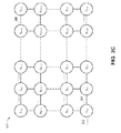
FIG. 2A shows an example sparse-dense transform unit 200. The sparse-dense transform unit 200 may correspond to the sparse-dense transform unit 104. The sparse-dense transform unit 200 includes M-by-N sparse element access units X1,1 to XM,N that are physically or logically arranged into M rows and N columns, where M and N are integers that are equal to or greater than 1. In some implementations, the sparse-dense transform unit 200 may include additional circuitry configured to process data. In general, the sparse-dense transform unit 200 is configured to receive a request for a dense matrix, and to determine a dense matrix based on corresponding sparse elements that are accessible by sparse element access units X1,1 to XM,N. In general, each sparse element access unit is configured to access a designated set of sparse elements, and is described in more detail below with reference to FIGS. 3A-3B. In some implementations, a sparse element access unit may be a single instruction, multiple data (SIMD) processing device.
In some implementations, the sparse element access units X1,1 to XM,N may be physically or logically arranged into a two-dimensional mesh configuration. For example, the sparse element access unit X1,1 is directly coupled to the sparse element access units X1,2 and X2,1. As another example, the sparse element access unit X2,2 is directly coupled to the sparse element access units X2,1, X3,1, X2,3, and X1,2. The coupling between two sparse element access units may be an electrical connection, an optical connection, a wireless connection, or any other suitable connection.
In some other implementations, the sparse element access units X1,1 to XM,N may be physically or logically arranged into a two-dimensional torus configuration. For example, the sparse element access unit X1,1 is directly coupled to the sparse element access units X1,2, X2,1, X1,N, and XM,1. As another example, the sparse element access unit XM,N is directly coupled to the sparse element access units XM,N-1, XM-1,N, XM,1, and X1,N.
In some implementations, the sparse-dense transform unit 200 may be configured to partition the sparse elements transformed from dense matrices according to a set of predetermined conditions. Each row of the sparse element access units X1,1 to XM,N may be partitioned to access sparse elements transformed from specific dense matrices. For example, the sparse-dense transform unit 200 may be configured to access sparse elements transformed from dense matrices that correspond to 1,000 different database tables of a computer model. One or more of the database tables may have different sizes. The first row 202 of the sparse element access units may be configured to access sparse elements transformed from database table No. 1 to database table No. 100, the second row 204 of the sparse element access units may be configured to access sparse elements transformed from database table No. 101 to database table No. 300, and the M-th row 206 of the sparse element access units may be configured to access sparse elements transformed from database table No. 751 to database table No. 1,000. In some implementations, the partitions may be configured by hardware instructions before a processor accesses sparse elements using the sparse-dense transform unit 200.
Each column of the sparse element access units X1,1 to XM,N may be partitioned to access a subset of the sparse elements transformed from the specific dense matrices. For example, the dense matrix corresponding to database table No. 1 may be transformed into 1,000 sparse elements, where the 1,000 sparse elements are accessible by the first row 202 as described above. The sparse element access unit X1,1 may be configured to access sparse elements No. 1 to No. 200 of database table No. 1, and the sparse element access unit X1,2 may be configured to access sparse elements No. 201 to No. 500 of database table No. 1. As another example, the dense matrix corresponding to database table No. 2 may be transformed into 500 sparse elements, where the 500 sparse elements are accessible by the first row 202 as described above. The sparse element access unit X1,1 may be configured to access sparse elements No. 1 to No. 50 of database table No. 2, and the sparse element access unit X1,2 may be configured to access sparse elements No. 51 to No. 200 of database table No. 2. As another example, the dense matrix corresponding to database table No. 1,000 may be transformed into 10,000 sparse elements, where the 10,000 sparse elements are accessible by the M-th row 206 as described above. The sparse element access unit XM,1 may be configured to access sparse elements No. 1 to No. 2,000 of database table No. 1,000, and the sparse element access unit XM,N may be configured to access sparse elements No. 9,000 to No. 10,000 of database table No. 1,000.
FIG. 2B shows an example of how the sparse-dense transform unit 200 may request sparse elements using a two-dimensional mesh network of the sparse element access units. As an example, a processing unit may execute an instruction requesting the sparse-dense transform unit 200 for a dense one-dimensional vector generated using sparse elements No. 1 to No. 50 of database table No. 1, sparse elements No. 100 to No. 200 of database table No. 2, and sparse elements No. 9,050 to No. 9,060 of database table No. 1,000. After the sparse-dense transform unit 200 receives the request from the processing unit, the sparse-dense transform unit 200 may instruct the sparse element access unit X1,1 to broadcast a request for the sparse elements to the other sparse element access units in the mesh network. The sparse element access unit X1,1 may broadcast a request 222 to the sparse element access unit X1,2 and a request 224 to the sparse element access unit X2,1. After receiving the request 222, the sparse element access unit X1,2 may broadcast a request 226 to the sparse element access unit X1,3. In some implementations, a sparse element access unit may be configured to broadcast a request to another sparse element access unit based on a routing scheme. For example, the sparse element access unit X1,2 may not be configured to broadcast a request to the sparse element access unit X2,2 because the sparse element access unit X2,2 is configured to receive a broadcast from the sparse element access unit X2,1. The routing scheme may be static or dynamically generated. For example, the routing scheme may be a lookup table. In some implementations, a sparse element access unit may be configured to broadcast the request 224 to another sparse element access unit based on the request 224. For example, the request 224 may include identifications of the requested sparse elements (e.g., database table No. 1, sparse elements No. 1 to No. 50), and the sparse element access unit X1,2 may determine whether to broadcast the request 224 to the sparse element access unit X2,2 and/or the sparse element access unit X1,3 based on the identifications. The broadcast process propagates through the mesh network, where the sparse element access unit XM,N receives a request 230 from the sparse element access unit XM,N-1.
FIG. 2C shows an example of how the sparse-dense transform unit 200 may generate the requested dense matrix using the two-dimensional mesh network of the sparse element access units. In some implementations, after a sparse element access unit receives the broadcasted request, the sparse element access unit is configured to determine whether it is configured to access any of the requested sparse elements. For example, the sparse element access unit X1,1 may determine that it is configured to access sparse elements No. 1 to No. 50 of database table No. 1, but it is not configured to access sparse elements No. 100 to No. 200 of database table No. 2 or sparse elements No. 9,050 to No. 9,060 of database table No. 1,000. In response to determining that it is configured to access sparse elements No. 1 to No. 50 of database table No. 1, the sparse element access unit X1,1 may fetch sparse elements No. 1 to No. 50 of database table No. 1 from the data shard(s) where these sparse elements are being stored, and generate a dense matrix 242 based on these sparse elements.
As another example, the sparse element access unit X2,1 may determine that it is not configured to access any of the sparse elements No. 1 to No. 50 of database table No. 1, the sparse elements No. 100 to No. 200 of database table No. 2, or sparse elements No. 9,050 to No. 9,060 of database table No. 1,000. In response to determining that it is not configured to access any of the requested sparse elements, the sparse element access unit X2,1 may perform no further action.
As another example, the sparse element access unit X1,2 may determine that it is configured to access sparse elements No. 100 to No. 200 of database table No. 2, but it is not configured to access sparse elements No. 1 to No. 50 of database table No. 1 or sparse elements No. 9,050 to No. 9,060 of database table No. 1,000. In response to determining that it is configured to access sparse elements No. 100 to No. 200 of database table No. 2, the sparse element access unit X1,2 may fetch these sparse elements from the data shard(s) where these sparse elements are being stored, and generate a dense matrix 244 based on these sparse elements. In some implementations, after a sparse element access unit generates a dense matrix, the sparse element access unit may be configured to forward the dense matrix to the sender of the broadcast request. Here, the sparse element access unit X1,2 forwards the dense matrix 244 to the sparse element access unit X1,1.
As another example, the sparse element access unit XM,N may determine that it is configured to access sparse elements No. 9,050 to No. 9,060 of database table No. 1,000, but it is not configured to access sparse elements No. 1 to No. 50 of database table No. 1 or sparse elements No. 100 to No. 200 of database table No. 2. In response to determining that it is configured to access sparse elements No. 9,050 to No. 9,060 of database table No. 1,000, the sparse element access unit XM,N may fetch these sparse elements from the data shard(s) where these sparse elements are being stored, and generate a dense matrix 246 based on these sparse elements. In some implementations, after a sparse element access unit generates a dense matrix, the sparse element access unit may be configured to forward the dense matrix to the sender of the broadcast request. Here, the sparse element access unit XM,N forwards the dense matrix 246 to the sparse element access unit XM,N-1. In the next cycle, the sparse element access unit XM,N-1 is configured to forward the dense matrix 246 to the sparse element access unit XM,N-1. This process continues until the sparse element access unit X2,1 has forwarded the dense matrix 246 to the sparse element access unit X1,1.
In some implementations, the sparse-dense transform unit 200 is configured to transform the dense matrices generated by the sparse element access units and generate a dense matrix for the processor unit. Here, the sparse-dense transform unit 200 transforms the dense matrices 242, 244, and 246 into a dense matrix for the processor unit. For example, the dense matrix 242 may have dimensions of 100-by-10, the dense matrix 244 may have dimensions of 20-by-100, and the dense matrix 246 may have dimensions of 3-by-3. The sparse-dense transform unit 200 may transform the dense matrices 242, 244, and 246 into a vector with dimensions of 1-by-3009. Advantageously, the partitioning of the rows according to dense matrices (e.g., database tables) allows the sparse-dense transform unit 200 to obtain all the requested sparse elements after the generated dense matrices has propagated from column N to column 1. The partitioning of the columns reduces bandwidth bottlenecks caused by accessing too many sparse elements using only one of the sparse element access units.
FIG. 2D shows an example of how the sparse-dense transform unit 200 may update sparse elements based on a dense matrix using a two-dimensional mesh network of the sparse element access units. As an example, a processing unit may execute an instruction requesting the sparse-dense transform unit 200 to update the stored sparse elements using a dense one-dimensional vector generated using sparse elements No. 1 to No. 50 of database table No. 1 and sparse elements No. 9,050 to No. 9,060 of database table No. 1,000. After the sparse-dense transform unit 200 receives the request from the processing unit, the sparse-dense transform unit 200 may instruct the sparse element access unit X1,1 to broadcast a sparse elements update request to the other sparse element access units in the mesh network, where the sparse elements update request may include the dense one-dimensional vector provided by the processing unit. In some implementations, the sparse element access unit X1,1 may determine whether it is assigned to access the sparse elements included in the dense one-dimensional vector. In response to determining that it is assigned to access the sparse elements included in the dense one-dimensional vector, the sparse element access unit X1,1 may update the sparse elements stored in the data shard(s). Here, the sparse element access unit X1,1 determines that it is assigned to access sparse elements No. 1 to No. 50 of database table No. 1, and the sparse element access unit X1,1 executes an instruction to update these sparse elements in the data shard(s).
The sparse element access unit X1,1 may broadcast a sparse elements update request 252 to the sparse element access unit X1,2 and a sparse elements update request 254 to the sparse element access unit X2,1. After receiving the sparse elements update request 252, the sparse element access unit X1,2 may determine that it is not assigned to access the sparse elements included in the dense one-dimensional vector. The sparse element access unit X1,2 broadcasts a request 256 to the sparse element access unit X1,3. The broadcast process propagates through the mesh network, where the sparse element access unit XM,N receives a request 260 from the sparse element access unit XM,N-1. Here, the sparse element access unit XM,N determines that it is assigned to access sparse elements No. 9,050 to No. 9,060 of database table No. 1,000, and the sparse element access unit XM,N executes an instruction to update these sparse elements in the data shard(s).
FIG. 3A shows an example sparse element access unit 300. The sparse element access unit 300 may be any one of the sparse element access units X1,1 to XM,N. In general, the sparse element access unit 300 is configured to receive, from the node network 320, a request 342 to fetch sparse elements stored in one or more data shards, and to transform the fetched sparse elements into a dense matrix. In some implementations, a processing unit 316 sends a request to a sparse element access unit in the node network 320 for a dense matrix generated using sparse elements. The sparse element access unit may broadcast the request 342 to the sparse element access unit 300. The routing of the broadcast request 342 may be similar to the descriptions in FIG. 2B. The sparse element access unit 300 includes a request identification unit 302, a data fetch unit 304, a sparse reduce unit 306, a concatenation unit 308, a compress/decompress unit 310, and a split unit 312. The node network 320 may be a two-dimensional mesh network. The processing unit 316 may be similar to the processing unit 102.
In general, the request identification unit 302 is configured to receive the request 342 to fetch sparse elements stored in one or more data shards 330, and determine whether the sparse element access unit 300 is assigned to access the sparse elements indicated by the request 342. In some implementations, the request identification unit 302 may determine whether the sparse element access unit 300 is assigned to access the sparse elements indicated by the request 342 by using a lookup table. For example, if an identification of a particular requested sparse element (e.g., No. 1 of database table No. 1) is included in the lookup table, the request identification unit 302 may send a signal 344 to the data fetch unit 304 to fetch the particular requested sparse element. If an identification of a particular requested sparse element (e.g., No. 1 of database table No. 1) is not included in the lookup table, the request identification unit 302 may discard the received request. In some implementations, the request identification unit 302 may be configured to broadcast the received request to another sparse element access unit on the node network 320.
The data fetch unit 304 is configured to fetch one or more requested sparse elements from the data shards 330 in response to receiving the signal 344. In some implementations, the data fetch unit 304 includes one or more processors 322 a-322 k, where k is an integer. Processors 322 a-322 k may be vector processing units (VPU), array processing units, or any suitable processing units. In some implementations, the processors 322 a-322 k are arranged to be near the data shards 330 to reduce the latency between the processors 322 a-322 k and data shards 330. Based on the number of requested sparse elements that the sparse element access unit 300 are assigned to fetch, the data fetch unit 304 may be configured to generate one or more requests to be distributed among the processors 322 a-322 k. In some implementations, each of the processors 322 a-322 k may be assigned to specific sparse elements based on the identification of the sparse elements, and the data fetch unit 304 may be configured to generate one or more requests for the processors 322 a-322 k based on the identification of the sparse elements. In some implementations, the data fetch unit 304 may determine the processor assignment by using a lookup table. In some implementations, the data fetch unit 304 may general multiple batches for the processors 322 a-322 k, where each batch is a request for a subset of the requested sparse element. The processors 322 a-322 k are configured to independently fetch the assigned sparse elements from the data shards 330, and to forward the fetched sparse elements 346 to the sparse reduce unit 306.
The sparse reduce unit 306 is configured to reduce the dimensions of the fetched sparse elements 346. For example, each of the processors 322 a-322 k may generate a sparse element having dimensions of 100-by-1. The sparse reduce unit 306 may receive fetched sparse elements 346 having dimensions of 100-by-k, and to generate sparse-reduced elements 348 by reducing the dimensions of the fetched sparse elements 346 to 100-by-1 by logic operations, arithmetic operations, or a combination of both. The sparse reduce unit 306 is configured to output the sparse-reduced elements 348 to the concatenation unit 308.
The concatenation unit 308 is configured to rearrange and concatenate the sparse-reduced elements 348 to generate concatenated elements 350. For example, The sparse element access unit X1,1 may be configured to access sparse elements No. 1 to No. 200 of database table No. 1. Processor 322 a may return the fetched sparse element No. 10 to the sparse reduce unit 306 sooner than processor 322 b that is configured returns the fetched sparse element No. 5. The concatenation unit 308 is configured to rearrange the later-received sparse element No. 5 to be ordered before the earlier-received sparse element No. 10, and concatenate sparse elements No. 1 to No. 200 as the concatenated elements 350.
The compress/decompress unit 310 is configured to compress the concatenated elements 350 to generate a dense matrix 352 for the node network 320. For example, the compress/decompress unit 310 may be configure to compress the zero values in the concatenated elements 350 to improve the bandwidth of the node network 320. In some implementations, the compress/decompress unit 310 may decompress a received dense matrix. For example, the sparse element access unit 300 may receive a dense matrix from a neighboring sparse element access unit via the node network 320. The sparse element access unit 300 may decompress the received dense matrix, and may concatenate the decompressed dense matrix with the concatenated elements 350 to form updated concatenated elements that can be compressed and then output to the node network 320.
FIG. 3B shows an example of how the sparse element access unit 300 may update sparse elements based on a dense matrix received from the node network 320. As an example, a processing unit may execute an instruction requesting the sparse-dense transform unit to update the stored sparse elements using a dense one-dimensional vector generated using sparse elements No. 1 to No. 50 of database table No. 1 and sparse elements No. 9,050 to No. 9,060 of database table No. 1,000. After the sparse-dense transform unit receives the request from the processing unit, the sparse-dense transform unit may send a request 362 to instruct the sparse element access unit 300 to determine whether it is assigned to access the sparse elements included in the dense one-dimensional vector. The request identification unit 302 is configured to determine whether the sparse element access unit 300 is assigned to access the sparse elements included in the dense one-dimensional vector. In response to determining that the sparse element access unit 300 is assigned to access the sparse elements included in the dense one-dimensional vector, the request identification unit 302 may send an indication 364 to the split unit 312 to update the sparse elements stored in the data shard(s).
The split unit 312 is configured to transform a received dense matrix into sparse elements that can be updated in the data shards 330 by the data fetch unit 304. For example, the split unit 312 may be configured to transform the dense one-dimensional vector into multiple sparse elements, and instruct the data fetch unit 304 to update the sparse elements stored in the data shards 330 that the sparse element access unit 300 is assigned to fetch.
FIG. 4 is a flow diagram that illustrates an example of a process 400 for generating a dense matrix. The process 400 may be performed by a system, such as the sparse-dense transform unit 104 or the sparse-dense transform unit 200. The system may include a first group of sparse element access units and a second group of sparse element access units. For example, referring to FIG. 2A, the sparse-dense transform unit 200 may include M-by-N sparse element access units X1,1 to XM,N that are physically or logically arranged into M rows and N columns. Each row of the sparse element access units X1,1 to XM,N may be partitioned to access sparse elements transformed from specific dense matrices. In some implementations, the first group of sparse element access units may include a first sparse element access unit and a second sparse element access unit. For example, the first row of the sparse-dense transform unit 200 may include sparse element access units X1,1 and X1,2. In some implementations, the first group of sparse element access units and the second group of sparse element access units may arranged in a two-dimensional mesh configuration. In some implementations, the first group of sparse element access units and the second group of sparse element access units may be arranged in a two-dimensional torus configuration.
The system receives a request for an output matrix based on sparse elements including sparse elements associated with a first dense matrix and the sparse elements associated with a second dense matrix (402). For example, referring to FIG. 2B, a processing unit may execute an instruction requesting the sparse-dense transform unit 200 for a dense one-dimensional vector generated using sparse elements No. 1 to No. 50 of database table No. 1, sparse elements No. 100 to No. 200 of database table No. 2, and sparse elements No. 9,050 to No. 9,060 of database table No. 1,000.
In some implementations, the first sparse element access unit may receive a request for a plurality of sparse elements including the sparse elements associated with the first dense matrix and the sparse elements associated with the second dense matrix. The first sparse element access unit may transmit the request to the second sparse element access unit. For example, referring to FIG. 2B, after the sparse-dense transform unit 200 receives the request from the processing unit, the sparse-dense transform unit 200 may instruct the sparse element access unit X1,1 to broadcast a request for the sparse elements to the other sparse element access units in the mesh network. The sparse element access unit X1,1 may broadcast a request 222 to the sparse element access unit X1,2.
The system obtains the sparse elements associated with the first dense matrix fetched by a first group of sparse element access units (404). In some implementations, the first sparse element access unit may determine that an identity of a particular sparse element of the plurality of sparse elements matches with an identity of one of the first subset of the sparse elements associated with the first dense matrix. For example, referring to FIG. 2C, the sparse element access unit X1,1 may be configured to access sparse elements No. 1 to No. 200 of database table No. 1. The sparse element access unit X1,1 may determine that it is configured to access sparse elements No. 1 to No. 50 of database table No. 1, but it is not configured to access sparse elements No. 100 to No. 200 of database table No. 2 or sparse elements No. 9,050 to No. 9,060 of database table No. 1,000. In response to determining that the identity of the particular sparse element of the plurality of sparse elements matches with the identity of one of the first subset of the sparse elements associated with the first dense matrix, the first sparse element access unit may fetch the first subset of the sparse elements associated with the first dense matrix including the particular sparse element. For example, in response to determining that it is configured to access sparse elements No. 1 to No. 50 of database table No. 1, the sparse element access unit X1,1 may fetch sparse elements No. 1 to No. 50 of database table No. 1 from the data shard(s) where these sparse elements are being stored.
The second sparse element access unit may fetch a second, different, subset of the sparse elements associated with the first dense matrix. For example, referring to FIG. 2C, the sparse element access unit X1,2 may be configured to access sparse elements No. 51 to No. 200 of database table No. 2. In response to determining that it is configured to access sparse elements No. 100 to No. 200 of database table No. 2, the sparse element access unit X1,2 may fetch these sparse elements from the data shard(s) where these sparse elements are being stored.
The system obtains the sparse elements associated with the second dense matrix fetched by a second group of sparse element access units (406). For example, referring to FIG. 2C, the second group sparse element access units may be the M-th row of the M-by-N sparse element access units, where the sparse element access unit XM,N may be configured to access sparse elements No. 9,000 to No. 10,000 of database table No. 1,000. In response to determining that it is configured to access sparse elements No. 9,050 to No. 9,060 of database table No. 1,000, the sparse element access unit XM,N may fetch these sparse elements from the data shard(s) where these sparse elements are being stored, and generate a dense matrix 246 based on these sparse elements.
In some implementations, the first sparse element access unit may fetch the first subset of the sparse elements associated with the first dense matrix from a first data shard, and the second sparse element access unit may fetch the second, different, subset of the sparse elements associated with the first dense matrix from a second, different data shard. For example, referring to FIG. 1, the first sparse element access unit may fetch the first subset of the sparse elements associated with the first dense matrix from data shard 106 a, and the second sparse element access unit may fetch the second, different, subset of the sparse elements associated with the first dense matrix from data shard 106 b.
The system transforms the sparse elements associated with the first dense matrix and the sparse elements associated with the second dense matrix to generate an output dense matrix that includes the sparse elements associated with the first dense matrix and the sparse elements associated with the second dense matrix (408). For example, referring to FIG. 2C, the sparse-dense transform unit 200 may transform the dense matrices 242, 244, and 246 into a dense matrix for the processor unit.
In some implementations, the sparse elements associated with and first dense matrix and the sparse elements associated with second dense matrix may be multi-dimensional matrices, and the output dense matrix may be a vector. For example, the dense matrix 242 may have dimensions of 100-by-10, the dense matrix 244 may have dimensions of 20-by-100, and the dense matrix 246 may have dimensions of 3-by-3. The sparse-dense transform unit 200 may transform the dense matrices 242, 244, and 246 into a vector with dimensions of 1-by-3009.
FIG. 5 is a flow diagram that illustrates an example of a process 500 for generating a dense matrix. The process 500 may be performed by a system, such as the sparse-dense transform unit 104 or the sparse element access unit 300.
The system receives an indication for accessing the subset of the particular sparse elements (502). For example, referring to FIG. 3A, the data fetch unit 304 may be configured to receiving a signal 344 for fetching one or more requested sparse elements from the data shards 330. In some implementations, a request for particular sparse elements that are stored in one or more data shards may be received over a node network. For example, referring to FIG. 3A, the request identification unit 302 may be configured to receive a request 342 over a node network 320 to fetch sparse elements stored in data shards 330. The system may determine that the data fetch unit is assigned to handle a subset of the particular sparse elements. For example, the request identification unit 302 may be configured to determine whether the sparse element access unit 300 is assigned to access the sparse elements indicated by the request 342. In response to determining that the data fetch unit is assigned to handle a subset of the particular sparse elements, the indication may be generated for accessing the subset of the particular sparse elements. For example, if an identification of a particular requested sparse element (e.g., No. 1 of database table No. 1) is included in a lookup table, the request identification unit 302 may send a signal 344 to the data fetch unit 304 to fetch the particular requested sparse element.
The system determines, based on identifications of the subset of the particular sparse elements, a processor designation for fetching the subset of the particular sparse elements (504). For example, referring to FIG. 3A, the data fetch unit 304 includes one or more processors 322 a-322 k. Each of the processors 322 a-322 k may be assigned to specific sparse elements based on the identification of the sparse elements, and the data fetch unit 304 may be configured to generate one or more requests for the processors 322 a-322 k based on the identification of the sparse elements. In some implementations, the system may determine that the system is assigned to handle the subset of the particular sparse elements comprises determining that the system is assigned to handle a subset of the particular sparse elements based on a lookup table. For example, the data fetch unit 304 may determine the processor assignment by using a lookup table.
The system fetches, based on the designation and by a first processor of the plurality of processors, a first sparse element of the subset of the particular sparse elements (506). For example, referring to FIG. 3A, the data fetch unit 304 may instruct the processor 322 a to fetch a sparse element that is included in the signal 344.
The system fetches, based on the designation and by a second processor of the plurality of processors, a second sparse element of the subset of the particular sparse elements (508). For example, referring to FIG. 3A, the data fetch unit 304 may instruct the processor 322 b to fetch a different sparse element that is included in the signal 344.
In some implementations, a first matrix that includes the first sparse element from the first processor may be received, where the first matrix may have a first dimension. The system may generate a second matrix that includes the first sparse element, the second matrix having a second dimension that is smaller than the first dimension. For example, the sparse reduce unit 306 may be configured to reduce the dimensions of the fetched sparse elements 346. Each of the processors 322 a-322 k may generate a sparse element having dimensions of 100-by-1. The sparse reduce unit 306 may receive fetched sparse elements 346 having dimensions of 100-by-k, and to generate sparse-reduced elements 348 by reducing the dimensions of the fetched sparse elements 346 to 100-by-1 by logic operations, arithmetic operations, or a combination of both. The system may generate the output dense matrix, the output dense matrix may be generated based on the second matrix. For example, the concatenation unit 308 may be configured to rearrange and concatenate the sparse-reduced elements 348 to generate concatenated elements 350.
In some implementations, the first sparse element may be received at a first point of time, and the second sparse element may be received at a second, different, point of time. The system may determine an order of the first sparse element and the second sparse element for the output dense matrix. For example, referring to FIG. 3A, processor 322 a may return the fetched sparse element No. 10 to the sparse reduce unit 306 sooner than processor 322 b that is configured returns the fetched sparse element No. 5. The concatenation unit 308 is configured to rearrange the later-received sparse element No. 5 to be ordered before the earlier-received sparse element No. 10, and concatenate sparse elements No. 1 to No. 200 as the concatenated elements 350.
The system generates an output dense matrix based on a transformation that is applied to at least the first sparse element and the second sparse element (510). In some implementations, the system may compress the output dense matrix to generate a compressed output dense matrix. The system may provide the compressed output dense matrix to the node network. For example, the compress/decompress unit 310 may be configured to compress the concatenated elements 350 to generate a dense matrix 352 for the node network 320.
In some implementations, the system may receive a first dense matrix representing a dense matrix sent over the node network, and generate the output dense matrix based on the first dense matrix, the first sparse element, and the second sparse element. For example, the sparse element access unit 300 may receive a dense matrix from a neighboring sparse element access unit via the node network 320. The sparse element access unit 300 may decompress the received dense matrix, and may concatenate the decompressed dense matrix with the concatenated elements 350 to form updated concatenated elements that can be compressed and then output to the node network 320.
In some implementations, the one or more sparse elements of the particular sparse elements are multi-dimensional matrices, and the output dense matrix is a vector. Embodiments of the subject matter and the functional operations described in this specification can be implemented in digital electronic circuitry, in tangibly-embodied computer software or firmware, in computer hardware, including the structures disclosed in this specification and their structural equivalents, or in combinations of one or more of them. Embodiments of the subject matter described in this specification can be implemented as one or more computer programs, i.e., one or more modules of computer program instructions encoded on a tangible non transitory program carrier for execution by, or to control the operation of, data processing apparatus. Alternatively or in addition, the program instructions can be encoded on an artificially generated propagated signal, e.g., a machine-generated electrical, optical, or electromagnetic signal, that is generated to encode information for transmission to suitable receiver apparatus for execution by a data processing apparatus. The computer storage medium can be a machine-readable storage device, a machine-readable storage substrate, a random or serial access memory device, or a combination of one or more of them.
The term “data processing apparatus” encompasses all kinds of apparatus, devices, and machines for processing data, including by way of example a programmable processor, a computer, or multiple processors or computers. The apparatus can include special purpose logic circuitry, e.g., an FPGA (field programmable gate array) or an ASIC (application specific integrated circuit). The apparatus can also include, in addition to hardware, code that creates an execution environment for the computer program in question, e.g., code that constitutes processor firmware, a protocol stack, a database management system, an operating system, or a combination of one or more of them.
A computer program (which may also be referred to or described as a program, software, a software application, a module, a software module, a script, or code) can be written in any form of programming language, including compiled or interpreted languages, or declarative or procedural languages, and it can be deployed in any form, including as a stand alone program or as a module, component, subroutine, or other unit suitable for use in a computing environment. A computer program may, but need not, correspond to a file in a file system. A program can be stored in a portion of a file that holds other programs or data, e.g., one or more scripts stored in a markup language document, in a single file dedicated to the program in question, or in multiple coordinated files, e.g., files that store one or more modules, sub programs, or portions of code. A computer program can be deployed to be executed on one computer or on multiple computers that are located at one site or distributed across multiple sites and interconnected by a communication network.
The processes and logic flows described in this specification can be performed by one or more programmable computers executing one or more computer programs to perform functions by operating on input data and generating output. The processes and logic flows can also be performed by, and apparatus can also be implemented as, special purpose logic circuitry, e.g., an FPGA (field programmable gate array), an ASIC (application specific integrated circuit), or a GPGPU (General purpose graphics processing unit).
Computers suitable for the execution of a computer program include, by way of example, can be based on general or special purpose microprocessors or both, or any other kind of central processing unit. Generally, a central processing unit will receive instructions and data from a read only memory or a random access memory or both. The essential elements of a computer are a central processing unit for performing or executing instructions and one or more memory devices for storing instructions and data. Generally, a computer will also include, or be operatively coupled to receive data from or transfer data to, or both, one or more mass storage devices for storing data, e.g., magnetic, magneto optical disks, or optical disks. However, a computer need not have such devices. Moreover, a computer can be embedded in another device, e.g., a mobile telephone, a personal digital assistant (PDA), a mobile audio or video player, a game console, a Global Positioning System (GPS) receiver, or a portable storage device, e.g., a universal serial bus (USB) flash drive, to name just a few.
Computer readable media suitable for storing computer program instructions and data include all forms of non volatile memory, media and memory devices, including by way of example semiconductor memory devices, e.g., EPROM, EEPROM, and flash memory devices; magnetic disks, e.g., internal hard disks or removable disks; magneto optical disks; and CD ROM and DVD-ROM disks. The processor and the memory can be supplemented by, or incorporated in, special purpose logic circuitry.
To provide for interaction with a user, embodiments of the subject matter described in this specification can be implemented on a computer having a display device, e.g., a CRT (cathode ray tube) or LCD (liquid crystal display) monitor, for displaying information to the user and a keyboard and a pointing device, e.g., a mouse or a trackball, by which the user can provide input to the computer. Other kinds of devices can be used to provide for interaction with a user as well; for example, feedback provided to the user can be any form of sensory feedback, e.g., visual feedback, auditory feedback, or tactile feedback; and input from the user can be received in any form, including acoustic, speech, or tactile input. In addition, a computer can interact with a user by sending documents to and receiving documents from a device that is used by the user; for example, by sending web pages to a web browser on a user's client device in response to requests received from the web browser.
Embodiments of the subject matter described in this specification can be implemented in a computing system that includes a back end component, e.g., as a data server, or that includes a middleware component, e.g., an application server, or that includes a front end component, e.g., a client computer having a graphical user interface or a Web browser through which a user can interact with an implementation of the subject matter described in this specification, or any combination of one or more such back end, middleware, or front end components. The components of the system can be interconnected by any form or medium of digital data communication, e.g., a communication network. Examples of communication networks include a local area network (“LAN”) and a wide area network (“WAN”), e.g., the Internet.
The computing system can include clients and servers. A client and server are generally remote from each other and typically interact through a communication network. The relationship of client and server arises by virtue of computer programs running on the respective computers and having a client-server relationship to each other.
While this specification contains many specific implementation details, these should not be construed as limitations on the scope of any invention or of what may be claimed, but rather as descriptions of features that may be specific to particular embodiments of particular inventions. Certain features that are described in this specification in the context of separate embodiments can also be implemented in combination in a single embodiment. Conversely, various features that are described in the context of a single embodiment can also be implemented in multiple embodiments separately or in any suitable subcombination. Moreover, although features may be described above as acting in certain combinations and even initially claimed as such, one or more features from a claimed combination can in some cases be excised from the combination, and the claimed combination may be directed to a subcombination or variation of a subcombination.
Similarly, while operations are depicted in the drawings in a particular order, this should not be understood as requiring that such operations be performed in the particular order shown or in sequential order, or that all illustrated operations be performed, to achieve desirable results. In certain circumstances, multitasking and parallel processing may be advantageous. Moreover, the separation of various system modules and components in the embodiments described above should not be understood as requiring such separation in all embodiments, and it should be understood that the described program components and systems can generally be integrated together in a single software product or packaged into multiple software products.
Particular embodiments of the subject matter have been described. Other embodiments are within the scope of the following claims. For example, the actions recited in the claims can be performed in a different order and still achieve desirable results. As one example, the processes depicted in the accompanying figures do not necessarily require the particular order shown, or sequential order, to achieve desirable results. In certain implementations, multitasking and parallel processing may be advantageous.

Claims (15)

What is claimed is:
1. A system for transforming sparse elements to a dense matrix, the system comprising:
a first group of sparse element access units configured to fetch sparse elements associated with a first dense matrix, wherein the first group of sparse element access units includes:
a first sparse element access unit that is configured to fetch a first subset of the sparse elements associated with the first dense matrix, and
a second sparse element access unit that is configured to fetch a second, different, subset of the sparse elements associated with the first dense matrix; and
a second group of sparse element access units configured to fetch sparse elements associated with a second dense matrix that is different from the first dense matrix,
wherein the system is configured to:
receive a request for an output dense matrix based on sparse elements including sparse elements associated with the first dense matrix and sparse elements associated with the second dense matrix, wherein the first sparse element access unit is configured to receive a request for a plurality of sparse elements including the sparse elements associated with the first dense matrix and the sparse elements associated with the second dense matrix and to transmit the request to the second sparse element access unit;
obtain the sparse elements associated with the first dense matrix fetched by the first group of sparse element access units;
obtain the sparse elements associated with the second dense matrix fetched by the second group of sparse element access units; and
transform the sparse elements associated with the first dense matrix and the sparse elements associated with the second dense matrix to generate the output dense matrix that includes the sparse elements associated with the first dense matrix and the sparse elements associated with the second dense matrix.
2. The system of claim 1, wherein the first sparse element access unit is configured to:
determine that an identity of a particular sparse element of the plurality of sparse elements matches with an identity of one of the first subset of the sparse elements associated with the first dense matrix, and
wherein the first sparse element access unit is configured to fetch the first subset of the sparse elements associated with the first dense matrix including the particular sparse element in response to determining that the identity of the particular sparse element of the plurality of sparse elements matches with the identity of one of the first subset of the sparse elements associated with the first dense matrix.
3. The system of claim 1,
wherein the first sparse element access unit is configured to fetch the first subset of the sparse elements associated with the first dense matrix from a first data shard, and
wherein the second sparse element access unit is configured to fetch the second, different, subset of the sparse elements associated with the first dense matrix from a second, different data shard.
4. The system of claim 1,
wherein the first sparse element access unit is configured to transform the first subset of the sparse elements associated with the first dense matrix to generate a third dense matrix, and
wherein the second sparse element access unit is configured to:
receive the third dense matrix;
transform the second subset of the sparse elements associated with the second dense matrix to generate a fourth dense matrix; and
transform the third dense matrix with the fourth dense matrix to generate a fifth dense matrix that includes the first subset of the sparse elements associated with the first dense matrix and the second subset of the sparse elements associated with the first dense matrix.
5. The system of claim 1, wherein the first group of sparse element access units and the second group of sparse element access units are arranged in a two-dimensional mesh configuration.
6. The system of claim 1, wherein the first group of sparse element access units and the second group of sparse element access units are arranged in a two-dimensional torus configuration.
7. The system of claim 1, wherein the sparse elements associated with the first dense matrix and the sparse elements associated with the second dense matrix are multi-dimensional matrices, and the output dense matrix is a vector.
8. A method of transforming sparse elements to a dense matrix, the method comprising:
receiving a request for an output matrix based on sparse elements including sparse elements associated with a first dense matrix and sparse elements associated with a second dense matrix;
obtaining the sparse elements associated with the first dense matrix fetched by a first group of sparse element access units, wherein the first group of sparse element access units includes:
a first sparse element access unit that is configured to fetch a first subset of the sparse elements associated with the first dense matrix, and
a second sparse element access unit that is configured to fetch a second, different, subset of the sparse elements associated with the first dense matrix, and
wherein the first sparse element access unit is configured to receive a request for a plurality of sparse elements including the sparse elements associated with the first dense matrix and the sparse elements associated with the second dense matrix and to transmit the request to the second sparse element access unit;
obtaining the sparse elements associated with the second dense matrix fetched by a second group of sparse element access units; and
transforming the sparse elements associated with the first dense matrix and the sparse elements associated with the second dense matrix to generate an output dense matrix that includes the sparse elements associated with the first dense matrix and the sparse elements associated with the second dense matrix.
9. The method of claim 8, wherein fetching the first subset of the sparse elements associated with the first dense matrix further comprises:
determining, by the first sparse element access unit, that an identity of a particular sparse element of the plurality of sparse elements matches with an identity of one of the first subset of the sparse elements associated with the first dense matrix, and
in response to determining that the identity of the particular sparse element of the plurality of sparse elements matches with the identity of one of the first subset of the sparse elements associated with the first dense matrix, fetching the first subset of the sparse elements associated with the first dense matrix including the particular sparse element.
10. The method of claim 8,
wherein fetching the first subset of the sparse elements associated with the first dense matrix further comprises fetching the first subset of the sparse elements associated with the first dense matrix from a first data shard, and
wherein fetching the second, different, subset of the sparse elements associated with the first dense matrix comprises fetching the second, different, subset of the sparse elements associated with the first dense matrix from a second, different data shard.
11. The method of claim 8, wherein the first group of sparse element access units and the second group of sparse element access units are arranged in a two-dimensional mesh configuration.
12. The method of claim 8, wherein the first group of sparse element access units and the second group of sparse element access units are arranged in a two-dimensional torus configuration.
13. The method of claim 8, wherein the sparse elements associated with the first dense matrix and the sparse elements associated with the second dense matrix are multi-dimensional matrices, and the output dense matrix is a vector.
14. A system for transforming sparse elements to a dense matrix, the system comprising:
one or more processors configured to send a request for an output dense matrix based on sparse elements including sparse elements associated with a first dense matrix and sparse elements associated with a second dense matrix that is different from the first dense matrix;
a sparse-dense transform unit comprising:
a first group of sparse element access units configured to fetch the sparse elements associated with the first dense matrix, wherein the first group of sparse element access units includes:
a first sparse element access unit that is configured to fetch a first subset of the sparse elements associated with the first dense matrix, and
a second sparse element access unit that is configured to fetch a second, different, subset of the sparse elements associated with the first dense matrix, and
wherein the first sparse element access unit is configured to receive a request for a plurality of sparse elements including the sparse elements associated with the first dense matrix and the sparse elements associated with the second dense matrix and to transmit the request to the second sparse element access unit; and
a second group of sparse element access units configured to fetch the sparse elements associated with the second dense matrix,
wherein the sparse-dense transform unit is configured to:
receive the request for the output matrix;
obtain the sparse elements associated with the first dense matrix fetched by the first group of sparse element access units;
obtain the sparse elements associated with the second dense matrix fetched by the second group of sparse element access units; and
transform the sparse elements associated with the first dense matrix and the sparse elements associated with the second dense matrix to generate the output dense matrix that includes the sparse elements associated with the first dense matrix and the sparse elements associated with the second dense matrix.
15. The system of claim 14, wherein the first group of sparse element access units and the second group of sparse element access units are arranged in a two-dimensional torus configuration.
US15/389,381 2016-02-05 2016-12-22 Matrix processing apparatus Active US9798701B2 (en)

Priority Applications (5)

Application Number Priority Date Filing Date Title
US15/389,381 US9798701B2 (en) 2016-02-05 2016-12-22 Matrix processing apparatus
US15/695,144 US10417303B2 (en) 2016-02-05 2017-09-05 Matrix processing apparatus
US16/571,749 US10719575B2 (en) 2016-02-05 2019-09-16 Matrix processing apparatus
US16/928,242 US11366877B2 (en) 2016-02-05 2020-07-14 Matrix processing apparatus
US17/842,420 US20220391472A1 (en) 2016-02-05 2022-06-16 Matrix processing apparatus

Applications Claiming Priority (2)

Application Number Priority Date Filing Date Title
US15/016,420 US9805001B2 (en) 2016-02-05 2016-02-05 Matrix processing apparatus
US15/389,381 US9798701B2 (en) 2016-02-05 2016-12-22 Matrix processing apparatus

Related Parent Applications (1)

Application Number Title Priority Date Filing Date
US15/016,420 Continuation US9805001B2 (en) 2016-02-05 2016-02-05 Matrix processing apparatus

Related Child Applications (1)

Application Number Title Priority Date Filing Date
US15/695,144 Continuation US10417303B2 (en) 2016-02-05 2017-09-05 Matrix processing apparatus

Publications (2)

Publication Number Publication Date
US20170228343A1 US20170228343A1 (en) 2017-08-10
US9798701B2 true US9798701B2 (en) 2017-10-24

Family

ID=57708453

Family Applications (6)

Application Number Title Priority Date Filing Date
US15/016,420 Active US9805001B2 (en) 2016-02-05 2016-02-05 Matrix processing apparatus
US15/389,381 Active US9798701B2 (en) 2016-02-05 2016-12-22 Matrix processing apparatus
US15/695,144 Active US10417303B2 (en) 2016-02-05 2017-09-05 Matrix processing apparatus
US16/571,749 Active US10719575B2 (en) 2016-02-05 2019-09-16 Matrix processing apparatus
US16/928,242 Active US11366877B2 (en) 2016-02-05 2020-07-14 Matrix processing apparatus
US17/842,420 Pending US20220391472A1 (en) 2016-02-05 2022-06-16 Matrix processing apparatus

Family Applications Before (1)

Application Number Title Priority Date Filing Date
US15/016,420 Active US9805001B2 (en) 2016-02-05 2016-02-05 Matrix processing apparatus

Family Applications After (4)

Application Number Title Priority Date Filing Date
US15/695,144 Active US10417303B2 (en) 2016-02-05 2017-09-05 Matrix processing apparatus
US16/571,749 Active US10719575B2 (en) 2016-02-05 2019-09-16 Matrix processing apparatus
US16/928,242 Active US11366877B2 (en) 2016-02-05 2020-07-14 Matrix processing apparatus
US17/842,420 Pending US20220391472A1 (en) 2016-02-05 2022-06-16 Matrix processing apparatus

Country Status (8)

Country Link
US (6) US9805001B2 (en)
EP (2) EP4160448A1 (en)
JP (4) JP6524052B2 (en)
KR (4) KR101980365B1 (en)
CN (2) CN107045493B (en)
BR (1) BR102016030970A8 (en)
SG (2) SG10201808521PA (en)
TW (4) TWI624763B (en)

Cited By (4)

* Cited by examiner, † Cited by third party
Publication number Priority date Publication date Assignee Title
US20180060276A1 (en) * 2016-02-05 2018-03-01 Google Inc. Matrix processing apparatus
US10489481B1 (en) * 2017-02-24 2019-11-26 Cyber Atomics, Inc. Efficient matrix property determination with pipelining and parallelism
US10521458B1 (en) * 2016-08-25 2019-12-31 Cyber Atomics, Inc. Efficient data clustering
US10635739B1 (en) 2016-08-25 2020-04-28 Cyber Atomics, Inc. Multidimensional connectivity graph-based tensor processing

Families Citing this family (5)

* Cited by examiner, † Cited by third party
Publication number Priority date Publication date Assignee Title
JP6912703B2 (en) * 2017-02-24 2021-08-04 富士通株式会社 Arithmetic method, arithmetic unit, arithmetic program and arithmetic system
US10936942B2 (en) * 2017-11-21 2021-03-02 Google Llc Apparatus and mechanism for processing neural network tasks using a single chip package with multiple identical dies
CN108804684B (en) * 2018-06-13 2020-11-03 北京搜狗科技发展有限公司 Data processing method and device
US10719323B2 (en) 2018-09-27 2020-07-21 Intel Corporation Systems and methods for performing matrix compress and decompress instructions
CN113794709B (en) * 2021-09-07 2022-06-24 北京理工大学 Hybrid coding method for binary sparse matrix

Citations (16)

* Cited by examiner, † Cited by third party
Publication number Priority date Publication date Assignee Title
US5625836A (en) 1990-11-13 1997-04-29 International Business Machines Corporation SIMD/MIMD processing memory element (PME)
US5644517A (en) 1992-10-22 1997-07-01 International Business Machines Corporation Method for performing matrix transposition on a mesh multiprocessor architecture having multiple processor with concurrent execution of the multiple processors
US5655137A (en) 1992-10-21 1997-08-05 The United States Of America As Represented By The Secretary Of The Navy Method and apparatus for pre-processing inputs to parallel architecture computers
US5708836A (en) 1990-11-13 1998-01-13 International Business Machines Corporation SIMD/MIMD inter-processor communication
US20040153934A1 (en) 2002-08-20 2004-08-05 Hui Jin Methods and apparatus for encoding LDPC codes
US7587516B2 (en) 2001-02-24 2009-09-08 International Business Machines Corporation Class network routing
CN102141976A (en) 2011-01-10 2011-08-03 中国科学院软件研究所 Method for storing diagonal data of sparse matrix and SpMV (Sparse Matrix Vector) realization method based on method
US20120159489A1 (en) * 2010-12-20 2012-06-21 Oliver Schabenberger Systems and Methods for Generating a Cross-Product Matrix In a Single Pass Through Data Using Single Pass Levelization
US8250133B2 (en) 2001-02-24 2012-08-21 International Business Machines Corporation Massively parallel supercomputer
US8380778B1 (en) * 2007-10-25 2013-02-19 Nvidia Corporation System, method, and computer program product for assigning elements of a matrix to processing threads with increased contiguousness
US8549259B2 (en) 2010-09-15 2013-10-01 International Business Machines Corporation Performing a vector collective operation on a parallel computer having a plurality of compute nodes
US20130339506A1 (en) 2012-06-13 2013-12-19 International Business Machines Corporation Performing synchronized collective operations over multiple process groups
US8751556B2 (en) 2010-06-11 2014-06-10 Massachusetts Institute Of Technology Processor for large graph algorithm computations and matrix operations
US20150067009A1 (en) * 2013-08-30 2015-03-05 Microsoft Corporation Sparse matrix data structure
US20150169369A1 (en) 2013-11-13 2015-06-18 Reservoir Labs, Inc. Systems and methods for parallelizing and optimizing sparse tensor computations
US20150378962A1 (en) 2014-06-27 2015-12-31 Oracle International Corporation Approach For More Efficient Use Of Computing Resources While Calculating Cross Product Or Its Approximation For Logistic Regression On Big Data Sets

Family Cites Families (10)

* Cited by examiner, † Cited by third party
Publication number Priority date Publication date Assignee Title
US5765011A (en) 1990-11-13 1998-06-09 International Business Machines Corporation Parallel processing system having a synchronous SIMD processing with processing elements emulating SIMD operation using individual instruction streams
GB2251320A (en) * 1990-12-20 1992-07-01 Motorola Ltd Parallel processor
JP2557175B2 (en) * 1992-05-22 1996-11-27 インターナショナル・ビジネス・マシーンズ・コーポレイション Computer system
JP3348367B2 (en) * 1995-12-06 2002-11-20 富士通株式会社 Multiple access method and multiple access cache memory device
JP3639206B2 (en) * 2000-11-24 2005-04-20 富士通株式会社 Parallel matrix processing method and recording medium in shared memory type scalar parallel computer
US9170836B2 (en) * 2013-01-09 2015-10-27 Nvidia Corporation System and method for re-factorizing a square matrix into lower and upper triangular matrices on a parallel processor
JP6083300B2 (en) 2013-03-29 2017-02-22 富士通株式会社 Program, parallel operation method, and information processing apparatus
CN103984527B (en) * 2014-04-01 2017-12-15 杭州电子科技大学 Optimization Sparse Matrix-Vector multiplies the method for lifting incompressible pipe flow field simulation efficiency
US9805001B2 (en) * 2016-02-05 2017-10-31 Google Inc. Matrix processing apparatus
US9898441B2 (en) * 2016-02-05 2018-02-20 Google Llc Matrix processing apparatus

Patent Citations (16)

* Cited by examiner, † Cited by third party
Publication number Priority date Publication date Assignee Title
US5708836A (en) 1990-11-13 1998-01-13 International Business Machines Corporation SIMD/MIMD inter-processor communication
US5625836A (en) 1990-11-13 1997-04-29 International Business Machines Corporation SIMD/MIMD processing memory element (PME)
US5655137A (en) 1992-10-21 1997-08-05 The United States Of America As Represented By The Secretary Of The Navy Method and apparatus for pre-processing inputs to parallel architecture computers
US5644517A (en) 1992-10-22 1997-07-01 International Business Machines Corporation Method for performing matrix transposition on a mesh multiprocessor architecture having multiple processor with concurrent execution of the multiple processors
US8250133B2 (en) 2001-02-24 2012-08-21 International Business Machines Corporation Massively parallel supercomputer
US7587516B2 (en) 2001-02-24 2009-09-08 International Business Machines Corporation Class network routing
US20040153934A1 (en) 2002-08-20 2004-08-05 Hui Jin Methods and apparatus for encoding LDPC codes
US8380778B1 (en) * 2007-10-25 2013-02-19 Nvidia Corporation System, method, and computer program product for assigning elements of a matrix to processing threads with increased contiguousness
US8751556B2 (en) 2010-06-11 2014-06-10 Massachusetts Institute Of Technology Processor for large graph algorithm computations and matrix operations
US8549259B2 (en) 2010-09-15 2013-10-01 International Business Machines Corporation Performing a vector collective operation on a parallel computer having a plurality of compute nodes
US20120159489A1 (en) * 2010-12-20 2012-06-21 Oliver Schabenberger Systems and Methods for Generating a Cross-Product Matrix In a Single Pass Through Data Using Single Pass Levelization
CN102141976A (en) 2011-01-10 2011-08-03 中国科学院软件研究所 Method for storing diagonal data of sparse matrix and SpMV (Sparse Matrix Vector) realization method based on method
US20130339506A1 (en) 2012-06-13 2013-12-19 International Business Machines Corporation Performing synchronized collective operations over multiple process groups
US20150067009A1 (en) * 2013-08-30 2015-03-05 Microsoft Corporation Sparse matrix data structure
US20150169369A1 (en) 2013-11-13 2015-06-18 Reservoir Labs, Inc. Systems and methods for parallelizing and optimizing sparse tensor computations
US20150378962A1 (en) 2014-06-27 2015-12-31 Oracle International Corporation Approach For More Efficient Use Of Computing Resources While Calculating Cross Product Or Its Approximation For Logistic Regression On Big Data Sets

Non-Patent Citations (7)

* Cited by examiner, † Cited by third party
Title
Bell et al. "Efficient Sparse Matrix-Vector Multiplications on CUDA," NVIDIA Technical Report NVR-2008-004, Dec. 11, 2008, 32 pages.
Cherkassky et al. "Efficient mapping and implementation of matrix algorithms on a hypercube," Journal on a hypercube, 2(1), Sep. 1, 1988, 21 pages.
Extended European Search Report issued in European Application No. 16207251.6 dated Jul. 6, 2017, 11 pages.
Gremse et al. "GPU-accelerated sparse matrix-matrix multiplication by iterative row merging," SIAM Journal on Scientific Computing 37(1), Jan. 22, 2015, 19 pages.
Morad et al. "Efficient Dense and Sparse Matrix Multiplication on GP-SIMD," 24th International Workshop on Power and Timing Modeling, Optimization and Simulation, Sep. 29, 2014, 8 pages.
Singaporan Search Report and Written Opinion issued in Application No. 10-201610977Q, dated Aug. 15, 2017, 11 pages.
Zhang et al. "Impact and Application of Data Mining Algorithms Tuned Graph Representation Format for GraphChi," The 8th ACM Conference on Recommender Systems, Oct. 6, 2014, 4 pages.

Cited By (10)

* Cited by examiner, † Cited by third party
Publication number Priority date Publication date Assignee Title
US20180060276A1 (en) * 2016-02-05 2018-03-01 Google Inc. Matrix processing apparatus
US10417303B2 (en) * 2016-02-05 2019-09-17 Google Llc Matrix processing apparatus
US10719575B2 (en) 2016-02-05 2020-07-21 Google Llc Matrix processing apparatus
US11366877B2 (en) 2016-02-05 2022-06-21 Google Llc Matrix processing apparatus
US10521458B1 (en) * 2016-08-25 2019-12-31 Cyber Atomics, Inc. Efficient data clustering
US10621268B1 (en) 2016-08-25 2020-04-14 Cyber Atomics, Inc. Multidimensional tensor processing
US10635739B1 (en) 2016-08-25 2020-04-28 Cyber Atomics, Inc. Multidimensional connectivity graph-based tensor processing
US11106702B2 (en) 2016-08-25 2021-08-31 Cyber Atomics, Inc. Efficient data clustering
US10489481B1 (en) * 2017-02-24 2019-11-26 Cyber Atomics, Inc. Efficient matrix property determination with pipelining and parallelism
US10747846B2 (en) 2017-02-24 2020-08-18 Cyber Atomics, Inc. Efficient matrix property determination with pipelining and parallelism

Also Published As

Publication number Publication date
US10719575B2 (en) 2020-07-21
KR20170093698A (en) 2017-08-16
KR20230002254A (en) 2023-01-05
US20210034697A1 (en) 2021-02-04
CN112000919A (en) 2020-11-27
US10417303B2 (en) 2019-09-17
CN107045493B (en) 2020-08-18
KR101980365B1 (en) 2019-05-20
EP3203382A1 (en) 2017-08-09
TWI624763B (en) 2018-05-21
US20220391472A1 (en) 2022-12-08
KR102112094B1 (en) 2020-05-18
CN112000919B (en) 2022-04-05
KR102483303B1 (en) 2022-12-29
SG10201610977QA (en) 2017-09-28
US20200012705A1 (en) 2020-01-09
US11366877B2 (en) 2022-06-21
TWI781509B (en) 2022-10-21
US9805001B2 (en) 2017-10-31
JP2023021171A (en) 2023-02-09
US20170228341A1 (en) 2017-08-10
JP2017138965A (en) 2017-08-10
JP2019153333A (en) 2019-09-12
TW201826143A (en) 2018-07-16
EP4160448A1 (en) 2023-04-05
TW201732645A (en) 2017-09-16
KR20200053461A (en) 2020-05-18
US20180060276A1 (en) 2018-03-01
CN107045493A (en) 2017-08-15
US20170228343A1 (en) 2017-08-10
JP7187635B2 (en) 2022-12-12
KR20190054052A (en) 2019-05-21
JP6978467B2 (en) 2021-12-08
BR102016030970A2 (en) 2018-07-17
BR102016030970A8 (en) 2018-07-31
TW202131172A (en) 2021-08-16
JP6524052B2 (en) 2019-06-05
TWI670613B (en) 2019-09-01
KR102635985B1 (en) 2024-02-08
SG10201808521PA (en) 2018-11-29
JP2022000781A (en) 2022-01-04
TW202011226A (en) 2020-03-16
TWI718604B (en) 2021-02-11

Similar Documents

Publication Publication Date Title
US11366877B2 (en) Matrix processing apparatus
US9880976B2 (en) Matrix processing apparatus

Legal Events

Date Code Title Description
AS Assignment

Owner name: GOOGLE INC., CALIFORNIA

Free format text: ASSIGNMENT OF ASSIGNORS INTEREST;ASSIGNORS:NARAYANASWAMI, RAVI;NAGARAJAN, RAHUL;WOO, DONG HYUK;AND OTHERS;SIGNING DATES FROM 20160203 TO 20160204;REEL/FRAME:040804/0733

AS Assignment

Owner name: GOOGLE LLC, CALIFORNIA

Free format text: CHANGE OF NAME;ASSIGNOR:GOOGLE INC.;REEL/FRAME:044118/0740

Effective date: 20170929

STCF Information on status: patent grant

Free format text: PATENTED CASE

MAFP Maintenance fee payment

Free format text: PAYMENT OF MAINTENANCE FEE, 4TH YEAR, LARGE ENTITY (ORIGINAL EVENT CODE: M1551); ENTITY STATUS OF PATENT OWNER: LARGE ENTITY

Year of fee payment: 4