US9808024B1 - Quick release head assembly on cotton candy machine - Google Patents
Quick release head assembly on cotton candy machine Download PDFInfo
- Publication number
- US9808024B1 US9808024B1 US13/625,983 US201213625983A US9808024B1 US 9808024 B1 US9808024 B1 US 9808024B1 US 201213625983 A US201213625983 A US 201213625983A US 9808024 B1 US9808024 B1 US 9808024B1
- Authority
- US
- United States
- Prior art keywords
- motor shaft
- head
- motor
- spring clip
- shaft
- Prior art date
- Legal status (The legal status is an assumption and is not a legal conclusion. Google has not performed a legal analysis and makes no representation as to the accuracy of the status listed.)
- Active, expires
Links
Images


Classifications
-
- A—HUMAN NECESSITIES
- A23—FOODS OR FOODSTUFFS; TREATMENT THEREOF, NOT COVERED BY OTHER CLASSES
- A23G—COCOA; COCOA PRODUCTS, e.g. CHOCOLATE; SUBSTITUTES FOR COCOA OR COCOA PRODUCTS; CONFECTIONERY; CHEWING GUM; ICE-CREAM; PREPARATION THEREOF
- A23G3/00—Sweetmeats; Confectionery; Marzipan; Coated or filled products
- A23G3/02—Apparatus specially adapted for manufacture or treatment of sweetmeats or confectionery; Accessories therefor
- A23G3/10—Candy-pulling machines ; Processes or apparatus for making cotton candy or candy floss
-
- A—HUMAN NECESSITIES
- A23—FOODS OR FOODSTUFFS; TREATMENT THEREOF, NOT COVERED BY OTHER CLASSES
- A23G—COCOA; COCOA PRODUCTS, e.g. CHOCOLATE; SUBSTITUTES FOR COCOA OR COCOA PRODUCTS; CONFECTIONERY; CHEWING GUM; ICE-CREAM; PREPARATION THEREOF
- A23G3/00—Sweetmeats; Confectionery; Marzipan; Coated or filled products
- A23G3/0002—Processes of manufacture not relating to composition and compounding ingredients
- A23G3/0051—Candy-pulling processes; processes for making cotton candy or candy floss
-
- D—TEXTILES; PAPER
- D01—NATURAL OR MAN-MADE THREADS OR FIBRES; SPINNING
- D01D—MECHANICAL METHODS OR APPARATUS IN THE MANUFACTURE OF ARTIFICIAL FILAMENTS, THREADS, FIBRES, BRISTLES OR RIBBONS
- D01D5/00—Formation of filaments, threads, or the like
- D01D5/18—Formation of filaments, threads, or the like by means of rotating spinnerets
-
- Y—GENERAL TAGGING OF NEW TECHNOLOGICAL DEVELOPMENTS; GENERAL TAGGING OF CROSS-SECTIONAL TECHNOLOGIES SPANNING OVER SEVERAL SECTIONS OF THE IPC; TECHNICAL SUBJECTS COVERED BY FORMER USPC CROSS-REFERENCE ART COLLECTIONS [XRACs] AND DIGESTS
- Y10—TECHNICAL SUBJECTS COVERED BY FORMER USPC
- Y10T—TECHNICAL SUBJECTS COVERED BY FORMER US CLASSIFICATION
- Y10T279/00—Chucks or sockets
- Y10T279/34—Accessory or component
- Y10T279/3406—Adapter
- Y10T279/3412—Drive conversion
-
- Y—GENERAL TAGGING OF NEW TECHNOLOGICAL DEVELOPMENTS; GENERAL TAGGING OF CROSS-SECTIONAL TECHNOLOGIES SPANNING OVER SEVERAL SECTIONS OF THE IPC; TECHNICAL SUBJECTS COVERED BY FORMER USPC CROSS-REFERENCE ART COLLECTIONS [XRACs] AND DIGESTS
- Y10—TECHNICAL SUBJECTS COVERED BY FORMER USPC
- Y10T—TECHNICAL SUBJECTS COVERED BY FORMER US CLASSIFICATION
- Y10T279/00—Chucks or sockets
- Y10T279/34—Accessory or component
- Y10T279/3406—Adapter
- Y10T279/3418—Adapter for particular tool or workpiece
-
- Y—GENERAL TAGGING OF NEW TECHNOLOGICAL DEVELOPMENTS; GENERAL TAGGING OF CROSS-SECTIONAL TECHNOLOGIES SPANNING OVER SEVERAL SECTIONS OF THE IPC; TECHNICAL SUBJECTS COVERED BY FORMER USPC CROSS-REFERENCE ART COLLECTIONS [XRACs] AND DIGESTS
- Y10—TECHNICAL SUBJECTS COVERED BY FORMER USPC
- Y10T—TECHNICAL SUBJECTS COVERED BY FORMER US CLASSIFICATION
- Y10T29/00—Metal working
- Y10T29/53—Means to assemble or disassemble
- Y10T29/5313—Means to assemble electrical device
- Y10T29/53143—Motor or generator
Landscapes
- Life Sciences & Earth Sciences (AREA)
- Chemical & Material Sciences (AREA)
- Engineering & Computer Science (AREA)
- Food Science & Technology (AREA)
- Polymers & Plastics (AREA)
- Portable Nailing Machines And Staplers (AREA)
Abstract
An apparatus and method for quick release of a spinner head assembly of a cotton candy machine. The spinner head is snap-fit to the rotational output shaft of the motor of the cotton candy machine to prevent longitudinal separation between the two during operation. Intermeshing portions between the spinner head and the output shaft are configured to translate rotational torque between the two and thus translate rotational torque of the output shaft of the motor to the spinner head. Quick release of the head is possible by pulling on the head along the rotational axis of the output shaft to overcome the snap-fit. This allows longitudinal separation of the spinner head and disengages the intermeshing portions for complete removal of the head. Reattachment is possible by snap-fitting connection between head and output shaft.
Description
This application is a Continuation Application of U.S. Ser. No. 12/691,577 filed Jan. 21, 2010, now issued as U.S. Pat. No. 8,376,064 which claims priority under 35 U.S.C. §119 to provisional application Ser. No. 61/205,530 filed Jan. 21, 2009 and Ser. No. 61/212,174 filed Apr. 8, 2009, all of which are incorporated by reference in their entirety.
A. Field of the Invention
The present invention relates to cotton candy machines, and in particular, how the rotating or spinner head assembly of a cotton candy machine is detachable and re-attachable from and to the machine.
B. Problems in the Art
Cotton candy making machines have a relatively long history. They have retained their basic form. They typically utilize a rotating spinner head assembly. That head assembly rotates at substantial speeds (e.g. several thousand RPM) by connection to an electric motor in the base of the machine. An electric heating element is in the head. Therefore, electrical power must be provided to the spinning head. This usually requires something like a slip ring assembly to transfer electrical power to a base of the machine to the spinning spinner head. A raw cotton candy, sugar-based solution is poured into the head. The rotation of the head throws the sugary solution by centrifugal force out to the walls of the head and through screens or openings to basically create the fluffy cotton candy caramelized sugarized strains. Those strains are caught in a bowl that surrounds the head.
U.S. Pat. No. 3,036,532 and published U.S. Patent Application US2002/0062743 A1 illustrate several examples of these types of cotton candy machines. Details regarding them can be seen in those patents, which are incorporated by reference in their entireties herein as background information.
There are several interesting and subtly-related factors that come into play with these types of cotton candy machines. One is the relatively extreme rotational speeds of the head. These machines are utilized in a variety of settings; sometimes using workers that are not experts with these machines. The connection of the rotating head to the motor shaft must be robust. Even though the spinner heads are relatively lightweight, spinning at such high RPM creates substantially forces. These forces not only can include centrifugal force but, because of manufacturing tolerances, substantial vibration forces in different directions.
Additionally, the electrically-energized heating element in the head must maintain electrical connection to an electrical power source while the head is rotating. Thus, a variety of ways have been developed to try to reliably do so. Several are described in detail in the incorporated by reference patent and published patent application listed earlier. For electrical connections using conducting rings and brushes, the head-to-motor-shaft connection must be not only robust but also ensure that electrical power to the head is maintained when operating.
But moreover, the general operational environment of these machines creates rather unique issues. The sugary substance involved with cotton candy is messy, coats components, and can make it important to frequently clean the machine. It is desirable to restrain the substance to the bowl around the rotating head. It is desirable to be able to clean the bowl as well as the head. To do so thoroughly generally requires the ability to remove the bowl and the head from the machine. This can be antagonistic to having a robust connection between head and rotating shaft and a good electrical connection between head and remainder of the machine.
For example, over time the screens or small openings in typical cotton candy machine spinner heads get clogged with the cotton candy solution and must be cleaned out. One conventional way to attach a head to a motor drive shaft is with an Allen screw, bolt or pin or other set screw. It can be difficult for non-mechanical persons, or persons not familiar with the machine, to find and then remove this fastening mechanism to remove the head and reattach it in the secure manner.
A further consideration is that not only is it desirable that the head be detachable, but that both detachment and reattachment be as easy and efficient as possible. It is also desirable that reattachment provide high confidence to the operator that the reattachment is secure. It is not desirable to rely on an operator's mechanical skills to ensure good reattachment. There are also issues with expired conducting surfaces and motors when the head is removed from the base.
Attachment and detachment of the head 2 is achieved by tightening or loosening a single Allen or set screw 7 with an Allen Wrench tool 9 through a small blind hole 3 in housing or base 1. The head 2 can be marked for the orientation of the setscrew 7 (see visual dot 10 placed on the outside of head 2 in FIG. 1 ; this dot 10 can be lined up with the blind hole 3 in base to try to line up set screw 7 with blind hole 3 so that it can be accessed by Allen Wrench tool 9 through blind hole 3). However, there are difficulties with this arrangement. Aligning dot 10 with blind hole 3 is an approximation. It may not indicate consistent exact alignment. Thus, the user may have to find set screw 7 with wrench 9 by trial and error, as it is not possible to get a good visual view of set screw 7. Also, mark 10 might no longer be there or may not be visible after the machine is used for awhile. To remove head 2 then has to be done through even more trial and error to find setscrew 7 in blind hole 3. Note also that if the Allen wrench or other tool is lost or misplaced, it may be very difficult if not impossible to detach or attach the head at least until another appropriate tool is obtained.
Note that motor shaft 5 can have a flat spot 6 to receive the setscrew 7, to help ensure torque is transferred from motor 8 to the head 2. As can be appreciated, if said screw 7 is not firmly installed, forces generated by the high RPM rotating or spinner head can create vibrations or other forces which attempt to try to separate the rotating or spinner head from its shaft or which cause the motor shaft to slip relative the head. This could cause malfunction or at least poor operation. Even relatively small separation might also affect electrical connection between electrical brushes of a slip ring assembly in base 1 (see, e.g., FIGS. 2 and 11 ) and conducting rings on the head. Also, over time, the setscrew can dig into the motor shaft or can strip in its threads which create risk of malfunction or poor operation.
The single set screw is central to this state of the art detachable head assembly.
It can therefore be appreciated that it is a primary object, feature, aspect or advantage of the present invention to improve upon the existing state of the art.
Further objects, features, advantages, or aspects of the invention include:
-
- a. An apparatus and method to detach and attach a spinner head assembly of a cotton candy machine to the motor shaft easily, efficiently, and repeatedly.
- b. An apparatus and method to detach and attach a spinner head assembly without a tool.
- c. An apparatus and method to provide feedback with regard to when the spinner head is in the appropriate attached position.
- d. A method and apparatus which is not complex but is robust with respect to the competing factors involved with cotton candy machines including, but not limited to, high head rotational speeds, exposure to the sugary substances, exposure to heat, need to convey electricity from the base to the spinning head, and need for repeated attachment and disattachment over time.
- e. A method and apparatus which automatically handles exposure of conducting surfaces and moving parts when a spinner head is removed.
These and other objects, features, aspects and advantages of the invention will become more apparent with the accompanying specification.
A. Overview
For a better understanding of the invention, an example of one form it can take will now be described in detail. Reference will be taken to the appended figures. Reference numbers will be used to indicate certain parts and locations in the figures. Those reference numbers will refer to the same parts and locations throughout the figures unless otherwise indicated.
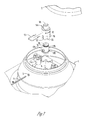
This exemplary embodiment is in the context of a cotton candy machine of the type indicated in the figures. This type of machine includes a spinner head 2 attached to a rotating output shaft 5 of an electrical motor 8. Electrical energy is conveyed to the spinner head 2 through a slip ring assembly, e.g. brush and conducting ring combination, (or other configuration), such as is known in the art. The drawings are shown without the conventional bowl around the spinner head. (An example such a bowl can be seen at FIG. 1 of published application US 2002/0062743 A1).
B. Apparatus
Typical basic components of a cotton candy machine have been previously described with regard to FIGS. 1-3 . A base 1 would house an electrical motor 8 having an output shaft 5. At the top of base 1 would be mounted a spinner head 2 which includes an electric heating element and a screen with openings, as is typical. Reference can be taken to U.S. Pat. No. 3,036,532 and published U.S. Patent Application US2002/0062743 A1, and to other commercially available machines for examples of conventional features.
-
- The
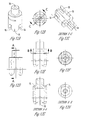
lower component 14B is secured to themotor shaft 5 by twosetscrews Lower component 14B will also be referred to asshaft adapter 14B. It adaptsmotor shaft 5 to the quick release aspect of this embodiment. - The
shaft extension component 14A is connected to thehead assembly 2 in the same way as with thehead 2 ofFIGS. 1-3 (by a bolt or machine screw axially through the top into a threaded bore).Upper component 14A will also be referred to asshaft extension 14A. It is mounted tohead 2 and has features with allow it (and thus head 2) to be quickly and easily attached and detached fromshaft adapter 14B. Thus, when shaft adapter is mounted onmotor shaft 5,head 2 is quickly and easily attached and detached frommachine body 1 by the quick attach/detach features ofcomponents 14A and B, as will be further illustrated and discussed below. -
Shaft extension 14A has two slots oropenings shaft extension 14A to receive opposite arms ofspring clip 20. -
Spring clip 20 is removably attached toshaft extension 14A by spreading the arms ofclip 20 and installing it intoslots 21A and B (seeFIGS. 15A-C ). When installed, the arms ofclip 20 are urged towards one another. This causes those arms to converge so that at least inner sides of the arms extend partially into interior bore 25 ofshaft extension 14A (seeFIG. 15D ). - A
chamfer 30 on the top edge ofshaft adapter 14B helps spreadspring clip 20 whenshaft extension 14A is pushed ontoshaft adapter 14B. - A
groove 31 near the top of theshaft adapter 14B then receives the inner sides of the arms ofspring clip 20 when thehead assembly 2 is engaged to theshaft adapter 14B. The spring force of the arms ofclip 20 force them intogroove 31 so that (a) clip arms snap-in, so to speak, intogroove 31 when they are aligned and (b) the cooperation ofclip 20 andgroove 31 prevent longitudinal movement ofshaft extension 14A fromshaft adapter 14B. - The
shaft extension 14A has multiplevertical slots 22 and the bottom edges of theslots 22 have flat faces. One set ofopposite slots 22 will engage the twosetscrews shaft adapter 14B to transfer rotational torque ofmotor shaft 5 fromshaft adapter 14B toshaft extension 14A. Also, the mating ofshaft extension 14A overshaft adapter 14B keeps those two parts aligned along the rotational axis ofmotor shaft 5.
- The
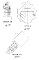
Therefore, as is shown in FIG. 4 , shaft extension and shaft adapter 14A and 14B provide a robust but non-complex way to connect a spinner head to a rotating motor shaft, which addresses the objects of the invention. Spring clip 20 in shaft extension 14A engages into groove 31 of shaft adapter 14B to keep the head assembly 2 in place. Uplifting force is required to detach the combination of shaft extension 14A/head assembly 2 from the shaft adapter 14B. In other words, to quickly and easily detach head 2 from base 1, without tools, the user simply has to pull upwardly on head 2 (generally along the rotational axis) with sufficient force to overcome the retaining force of clip 20 in groove 31. By selection of the characteristics of clip 20 relative to groove 31, the designer can make sure the retaining force is sufficient for normal operating conditions but easily manually overcome by most persons. As indicated, because clip 20 is basically and primarily retaining head 2 from vertical separation during operation, this retaining force does not need to be very high. Therefore, a normal person can detach head 2 by pulling up on head 2 by relatively low force. The person pulls until clip 20 spreads sufficiently to release shaft extension 14A. The person then simple continues to lift head 2 until shaft extension 14A clears shaft adapter 14B. Because electrical connections are of the slip ring nature, not other components need to be detached or disconnected to allow the user to completely remove head 2 and, for example, move it is an entirely different location such as a sink to wash it out. And then, when it is desired to re-attach head 2 to body 1, the user simply reverses the process. Head 2 is brought over base 1 so that bore 25 in shaft extension 14A is aligned with the top of shaft adapter 14B. This can be done easily and quickly by sight. Head 2 is then dropped downwardly. Note that multiple vertical slots 22 in the lower end of shaft extension 14A (as well as the widened openings into each slot 22) help a set of slots 22 “find” the set of oppositely horizontally extending set screws 17A and B on shaft adapter 14B. The user may have to rotate head 2 just slightly to seat a set of slots 22 onto setscrews 17A and B. Once a set of slots 22 finds setscrews 17A and B, shaft extension 14A is basically aligned with to the vertical rotational axis of motor shaft 5. All that is left is for the user to continue to lower head 2 downwardly until the user senses (feels, hears, etc.) clip 20 “snap into” or find groove 31 in shaft adapter 14B. A good portion of inner bore 25 of shaft extension 14A is thus mated with close tolerance over the exterior of shaft adapter 14B. Rotational movement of motor shaft 5 is imparted to head 2 by vertical slots 22 of shaft extension 14 A capturing setscrews 17A and B of shaft adapter 14B. And separation along the rotational axis of head 2 from base 1 is prevented by gravity and clip 20.
Note also that the inter-cooperation of shaft adapter 14B and shaft extension 14A can be added to a conventional machine/head ½ quickly and easily as a retro-fit, or can be original equipment. Shaft adapter 14B is installed to motor shaft 5 by tightening two set screws 17A and B. Shaft extension 14A is installed to head 2 by use of a single bolt. Once components 14B and 14A are installed on motor shaft 5 and head 2, respectively, attachment and detachment of head 2 to base 1, over repeated times, is possible. But further, if head 2 must be replaced (and/or base 1), either shaft extension 14A or shaft adapter 14B can be quickly and easily uninstalled from its respective head or base and used with a new head or base.
By also referring to FIGS. 5-8 , details of how spinner head 2 is releasably assembled onto motor shaft 5 by the cooperation of shaft extension 14A and shaft adapter 14B. The sectional view of FIG. 5 shows how spring clip 20 cooperates with groove 31. FIG. 6 , a different sectional view, shows how setscrews 17A and 17B cooperate with vertical slots 22 of shaft extension 14A and secure the shaft adapter 14B to the motor shaft 5. Two setscrews provide a more robust connection to the motor shaft then one (compare FIG. 3 and FIG. 6 ). And, with this embodiment of the invention, set screws 17A and B do not have to be frequently accessed because of shaft extension 14A and its quick release function. Two setscrews 17A and 17B on shaft adapter 14B basically lock shaft adapter 14B onto the motor shaft 5 and also drive the shaft extension 14A for rotation. Shaft adapter 14B, once installed on motor shaft 5, stays on shaft 5. Shaft extension 14A stays with spinner head 2 when head 2 is removed.
C. Operation
Furthermore, the ability to attach spinner head 2 to shaft adapter 14B depends primarily on just the ability to match up shaft extension 14A with shaft adapter 14B. Shaft extension 14A is previously attached to head 2 (see bolt or machine screw 11 threaded into threaded bore 24 in the top of shaft extension 14A. Even a novice operator can easily align those components (head 2 with shaft extension 14A bolted to it) and lower the head downward until there is positive tactile feedback that spring clip 20 has snapped into groove 31. Even the novice operator can feel that “snap” or “click”. This provides high assurance that head 2 is in correct place and attached. As noted, the geometry of the parts cooperate to automatically initially guide the open bottom end of shaft extension 14A onto the top end of shaft adapter 14B, guide a pair of vertical slots 22 of shaft extension 14A over set screws 17A and B of shaft adapter 14B, and spread spring clip 20 sufficiently until it is lowered to where it is aligned with groove 31. The inherent pre-stressed resilient forces of spring clip 20 then cause its legs to converge and snap into groove 31. The components and their characteristics (e.g., types and characteristics of the materials) are selected according to need. For example, spring clip 20 is a size, material, and spring constant and force to hold shaft extension 14A/head 2 to shaft adapter 14B at its normal rotational speeds, but allow separation along the rotational axis with relatively small manual force (and to do so over many attachments and detachments).
As previously noted, other subtle aspects of the combination of shaft extension and shaft adapter 14A and 14B result. For example, part 14B transfers rotational torque between the shaft of the motor and the head through part 14A. Slots 22 in shaft extension 14A provide built-in torque transfer surfaces. This is in distinction to just the single setscrew of FIGS. 1-3 and sometimes one flattened side 6 of motor shaft 5.
Detachment of head 2 simply requires the user to lift upwardly with sufficient force to overcome the holding force of spring clip 20 in groove 31. This is a quick and relatively easy release without tools. As illustrated in FIGS. 5, 8, and 17A -G, spring clip 20 fits partially in groove 31 when shaft extension 14A is attached to shaft adapter 14B. The resiliency of spring clip 20 is selected to give a robust connection between 14A and 14B relative to the rotation of the head around its rotational axis but also allow detachment of the head by overcoming that clamping/retaining action of spring clip 30 relative to groove 31. Again, this does not require any tool or any mechanical proficiency.
Attachment and detachment can be repeated per the above described steps multiple times over the life of the machine. If spring clip 20 loses its effectiveness, it can simply be replaced.
It is therefore respectfully submitted that the exemplary embodiment meets at least all of the stated objectives of the invention.
D. Alternatives and Options
The above-described embodiment is but one form the invention can take and is neither inclusive or exclusive. Variations obvious to those skilled in the art would be included within the invention.
1. Miscellaneous Examples of Alternatives and Options
For example, the materials with which the components of the invention can be made can vary according to need or desire. One example would be metal of sufficient strength for these purposes. The metal for parts 14A and 14B can be, for example, the same type of metal as connection 4 of FIG. 2 . This does not preclude other materials from being used if they meet operational requirements.
Likewise, the specific type of quick release connection between the upper and shaft adapters can vary. So can the attachment of the shaft adapter to the motor output shaft.
It is possible that shaft extension 14A might be built-in or made integral to head 2. It is also possible that shaft adapter 14B could be built-in or made integral with motor shaft 5.
2. Specific Example of Automatic Power Disconnect on Spinner Head Detachment
An optional additional feature can be as follows with reference to the Figures.
A power supply cut off feature can be added to the machine. It works as a safety switch when the head is detached and works as a guard against electrical shock and exposed wires or conducting surfaces from coming in contact from the operator of the machine (or any person) via a proximity switch or power coupling that turns power off from the head base when the head is detached.
This can be operatively installed on a cotton candy machine in a variety of ways with a variety of components. One way, as noted above, is simply a circuit that allows electrical power to the spinner head of the machine so long as the circuit senses the removable spinner head is within a certain proximity to the base of the machine (e.g., is attached to the base), but disallows electrical power to the spinner head (or to the electrical conductors adapted to supply electricity to the head) if it sensed the head is outside acceptable proximity (e.g., removed).
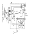
Proximity sensors/switches are commercial available and well known. This option is diagrammatically indicated at FIG. 11 . Proximity sensor 130 could be attached to head 2 (or base 1) in a position that it would produce a signal indicative that head 2 is within a distance from base 1 that is indicative head 2 is installed in operative position on base 1. The signal from sensor 130 could be communicated to a component which could automatically disable electrical power to the slip ring assembly 106 so that exposed conducting surfaces would automatically be prevented from being connected to an electrical power source (even if the main power switch of the machine were on). Essentially it would automatically override that main switch. As indicated in FIG. 11 , one component to disable power would be a relay 116 with associated contacts 117 and 118. Contacts 117 and 118 would be normally open (non-conducting). However, if the signal from the proximity sensor indicating head 2 is attached to base 1 is received by relay 116, it would energize and close (make conducting) the contacts 117 and 118. Thus, when motor switch 112 and/or heater switch 120 is/are turned on (conducting), contacts 117 and 118 would be closed and would allow motor 8 and/or heater 102 to receive electrical power. Since head 2 is installed on base 1, the slip ring assembly 106 is not exposed to the operator. The operator runs the machine by manual selection of main motor switch 112 for rotation of head 2, heater switch 120 for creating heat in head 2, and temperature control 122 (e.g. a rheostat) for setting temperature of heater 102 in head 2. So long as the proximity sensor senses head 2 is attached to base 1, this operational mode stays in place. However, if the proximity sensor senses head 2 is moved a certain distance away from its normal installed position (by calibration of the proximity sensor to a certain separation distance), it will discontinue sending its signal to the relay. This would then de-energize relay 116, which would cause contacts 117 and 118 to return to normal open (non-conducting) state. Thus, electrical power to (a) the motor and (b) the slip ring assembly would be automatically disabled. The motor could not run and even though there would not be a complete electrical path through the slip ring assembly, even if someone would complete or short that circuit at the slip ring assembly, there would be no electrical power available to it.
An alternative automatic disconnect of electrical power upon spinner head detachment is shown with particular reference to FIGS. 9-11 . It is to be understood this is but a second way to effectuate automatic power disconnect upon spinning head detachment. It is given by way of example only and is neither inclusive nor exclusive of the ways.
As mentioned, electrical power is needed to the spinner head heater 102, when the cotton candy machine is operated to produce cotton candy. A typical way of providing such power with a slip ring assembly 106, such as are well known, that uses conductive slip rings and brushes to conduct electricity to the spinning head during operation. Such slip rings and brushes have electrically conductive surfaces. When the spinner head is removed, they can be exposed. This is an issue because if the heat switch 120 is on, even though the circuit is open, if someone bridges or shorts certain brushes together, there is a risk of electrical shock or damage to components. Also, removal of head 2 can expose motor shaft 5. If motor switch 112 is on, a user or other person in the vicinity may be exposed to a fast rotating motor shaft 5.
Automatic disconnect of electrical power to any exposed parts in the slip ring assembly and/or motor shaft can be effectuated as shown in the wiring diagram of FIG. 11 . This electric circuit operates as follows.
Changing the double pole, single throw motor switch 112 state from open to closed enables power to the transformer 114 primary side and the relay 116 normally opened contacts 117, 118. The transformer secondary is a series circuit which flows through the relay coil 116 and slip ring interlock brushes 104.
The slip ring interlock brushes 104 associated with the transformer secondary, when not properly engaged (e.g. when spinning head 2 is lifted from base 1) prevent current flow through the relay 116 coil. The slip ring interlock brushes 104 associated with the transformer secondary, when properly engaged (e.g. when head 2 is in operative installed position on base 1) allow current to flow through the relay 116 coil. The current flow through relay coil 116 causes its normally open contacts to close; allowing power to motor switch 112 and heater switch 120. With the relay coil energized, motor 8 operates immediately. Changing the double pole, single throw heater switch 120 state from open to closed enables the power supply hot side to the temperature control 122 and the common side to the heater 102. The power hot side is switched on and off according to the temperature setting of the temperature control 122.
Therefore, when spinning head 2 is fully attached to base 1 as in FIG. 9 , relay 116 allows both motor and heat switches 112 and 120 and temperature control switch 122 to be active and allows them to control power to motor 8, heat to the heater 102 in the spinning head 2, and temperature control of the heater 102 in the spinning head 2. In other words, electrical power is available to be switched on and off to the motor 8 and controlled in magnitude to the heater 102 according to operation of motor switch 112, heat switch 120, and temperature control 122. This means that the electrical conducting circuit path to the motor 8 and to the heater 102 in the spinner head 2 through the slip ring assembly 106 (with brushes 105 and conducting rings 107) is available if switched on.
But on the other hand, if spinning head 2 is removed, relay 116 does not open relay contacts 117 and 118 associated with it, and in fact, prevents that from happening. Therefore, regardless of whether motor switch 112 or heat switch 120 is turned on, electrical power cannot reach motor 8 or the slip ring assembly 106. It is only when spinner head 2 is reattached in operating condition that this can occur.
As can be seen from FIG. 11 , disconnection of interlock brushes 105A and B (one in base 1, one in head 2) automatically disconnects any possibility of electrical power through the primary side of transformer 114. Therefore, this automatically prevents energization of its secondary side and energization of relay 116. This causes relay contacts 117 and 118 to return to their normally open (non-conducting) state. And, therefore, this prevents electrical power from reaching motor 8 or slip ring assembly 106. Importantly, this is regardless of whether motor switch 112, heat switch 120, or temperature control 122 are on (conducting). Thus, the user or others are not exposed to the possibility of motor shaft 5 turning (or being inadvertently turned on) with head 2 removed. The user or others are not exposed to the possibility that a set of brushes in base 1 could be shorted and electrical current flowing through conducting surfaces exposed to the user or others in the vicinity.
Claims (8)
1. A quick release apparatus for attachment of a spinner head assembly having a motor shaft receiver to a cotton candy machine electric motor having an output shaft along a motor shaft rotational axis comprising:
a. a quick release between the spinner head assembly and the electric motor along the output shaft comprising:
i. a two piece releasable mating connection between first and second portions allowing the second portion to slide over the first portion along the motor shaft rotational axis;
ii. a spring clip radial receiving slot through the second portion;
iii. a radial groove in the first portion;
iv. a removable externally-accessible spring clip comprising resilient opposite arms that are extended substantially parallel to one another;
v. the spring clip and the groove being related such that when the second portion slides over the first portion and the slot and groove align, the spring clip resiliently is mounted around an exterior portion of the second portion, and has a part which engages the groove in the first portion through the slot in the second portion, wherein inner sides of the arms of the spring clip install into the slot of the second portion and then are urged to snap-in to the radial groove in the first portion, to prevent separation along the rotational axis of the output shaft of the first and second portions but allows quick release detachment of the spinner head assembly from the motor by overcoming holding three of the spring clip in the groove.
2. The apparatus of claim 1 further comprising a structure on the second portion that is complimentary with structure on the first portion such that when the first and second portions are connected the complimentary structure transfers rotational torque between the two portions of the output shaft.
3. The apparatus of claim 2 , wherein:
a. the second portion comprises a motor shaft extension comprising:
i. a longitudinal axis,
ii. a motor shaft end with a receiver for removable connection to a motor shaft portion connected to the motor, and
iii. an opposite end, and
iv. wherein the structure on the second component portion comprises a radially extending member extending radially outwardly from the longitudinal axis of the motor shaft extension, and
b. the first portion comprises a separable motor shaft adaptor, the motor shaft adaptor comprising:
i. a longitudinal axis,
ii. a spinner head end with a connection for the spinner head, and
iii. an opposite end with a receiver adapted to matingly fit over the opposite end of the motor shaft extension for a distance down to and past the radially extending member,
iv. wherein the structure on the first component comprises an elongated slot having an open end at the opposite end of the second component and running longitudinally a distance towards the spinner head end and adapted to receive the radially extending member and transfer rotational motion from the motor shaft extension to the separable motor shaft adaptor, and therefore from the motor to the spinner head.
4. The apparatus of claim 3 further comprising a second radially extending member on the motor shaft extension and a second elongated slot on the motor shaft adaptor.
5. A quick release apparatus for attachment of a spinner head assembly including an electric heating element to a cotton candy machine electric motor output shaft having a motor shaft rotational axis comprising:
a. a motor shaft adaptor removeably mounted to the output shaft of the electric motor for the cotton candy machine along the motor shaft rotational axis;
b. a motor shaft extension removeably mounted to a spinner head assembly of the cotton candy machine;
c. a quick release connection between the motor shaft extension and the motor shaft adaptor comprising:
i. a releasable mating connection allowing the motor shaft extension to slide over the motor shaft adaptor along the motor shaft rotational axis;
ii. a spring clip radial receiving slot through of the motor shaft extension;
iii. a radial groove in the motor shaft adaptor;
iv. a removable, externally-accessible spring clip comprising resilient opposite arms that are extended substantially parallel to one another;
v. the spring clip and the groove being related such that when the motor shaft extension is lowered to the motor shaft adaptor and the slot and groove align, the spring clip resiliently is mounted around the exterior of the motor shaft extension and has a part which engages the groove in the motor shaft adaptor through the slot in the motor shaft extension, wherein inner sides of the arms of the spring clip install into the slot of the motor shaft extension and then are urged to snap-in to the radial groove in the motor shaft adaptor, to prevent separation along the rotational axis of the output shaft of the motor shaft extension and the motor shaft adaptor but allows quick release detachment of the spinner head assembly from the motor by overcoming holding force of the spring clip in the groove.
6. The apparatus of claim 5 further comprising a switchable electrical conducting path from an electrical power source to the motor and a slip ring assembly of the cotton candy machine when the spinning head with electric heating element is operatively attached to a base of the cotton candy machine.
7. The apparatus of claim 6 wherein a relay is energized by a closed electrical path through an interlock brush assembly when the spinner head is in operative position.
8. The apparatus of claim 7 wherein the relay is energized by a transformer.
Priority Applications (1)
| Application Number | Priority Date | Filing Date | Title |
|---|---|---|---|
| US13/625,983 US9808024B1 (en) | 2009-01-21 | 2012-09-25 | Quick release head assembly on cotton candy machine |
Applications Claiming Priority (4)
| Application Number | Priority Date | Filing Date | Title |
|---|---|---|---|
| US20553009P | 2009-01-21 | 2009-01-21 | |
| US21217409P | 2009-04-08 | 2009-04-08 | |
| US12/691,577 US8376064B1 (en) | 2009-01-21 | 2010-01-21 | Quick release head assembly on cotton candy machine |
| US13/625,983 US9808024B1 (en) | 2009-01-21 | 2012-09-25 | Quick release head assembly on cotton candy machine |
Related Parent Applications (1)
| Application Number | Title | Priority Date | Filing Date |
|---|---|---|---|
| US12/691,577 Continuation US8376064B1 (en) | 2009-01-21 | 2010-01-21 | Quick release head assembly on cotton candy machine |
Publications (1)
| Publication Number | Publication Date |
|---|---|
| US9808024B1 true US9808024B1 (en) | 2017-11-07 |
Family
ID=47682705
Family Applications (2)
| Application Number | Title | Priority Date | Filing Date |
|---|---|---|---|
| US12/691,577 Active 2030-10-26 US8376064B1 (en) | 2009-01-21 | 2010-01-21 | Quick release head assembly on cotton candy machine |
| US13/625,983 Active 2031-10-13 US9808024B1 (en) | 2009-01-21 | 2012-09-25 | Quick release head assembly on cotton candy machine |
Family Applications Before (1)
| Application Number | Title | Priority Date | Filing Date |
|---|---|---|---|
| US12/691,577 Active 2030-10-26 US8376064B1 (en) | 2009-01-21 | 2010-01-21 | Quick release head assembly on cotton candy machine |
Country Status (1)
| Country | Link |
|---|---|
| US (2) | US8376064B1 (en) |
Cited By (1)
| Publication number | Priority date | Publication date | Assignee | Title |
|---|---|---|---|---|
| US10244773B2 (en) * | 2015-07-01 | 2019-04-02 | Agatsuma Co., Ltd | Cotton candy preparing device |
Families Citing this family (3)
| Publication number | Priority date | Publication date | Assignee | Title |
|---|---|---|---|---|
| JP6605858B2 (en) * | 2015-07-01 | 2019-11-13 | 株式会社アガツマ | Cotton candy manufacturing equipment |
| USD799881S1 (en) * | 2016-01-08 | 2017-10-17 | Nostalgia Products Llc | Cotton candy machine |
| US11642852B2 (en) * | 2020-07-01 | 2023-05-09 | International Business Machines Corporation | Rotational material scattering additive manufacturing device |
Citations (36)
| Publication number | Priority date | Publication date | Assignee | Title |
|---|---|---|---|---|
| US792710A (en) * | 1904-12-05 | 1905-06-20 | Albert Kochs | Machine for making silk-candy. |
| US816114A (en) * | 1904-11-04 | 1906-03-27 | Electric Candy Machine Company | Candy-machine. |
| US847366A (en) | 1906-06-13 | 1907-03-19 | Ralph E Pollock | Candy-spinning machine. |
| US1489342A (en) * | 1922-05-29 | 1924-04-08 | George E Brent | Candy machine |
| US1541378A (en) * | 1924-02-16 | 1925-06-09 | Parcell John | Confection apparatus |
| US2760258A (en) * | 1951-06-15 | 1956-08-28 | Richard H Jordan | Device for quickly connecting and disconnecting two bodies |
| US2844471A (en) * | 1957-04-12 | 1958-07-22 | Johanna C Boardway | Package containing article with delicate surface |
| US3036532A (en) * | 1960-06-28 | 1962-05-29 | Bowe John | Cotton candy machine with product of alternating colors |
| US3232244A (en) * | 1962-03-29 | 1966-02-01 | Link Res And Dev Corp | Cotton candy machine |
| US3759336A (en) | 1972-01-21 | 1973-09-18 | D Marcovitz | Interchangeable power operated tools |
| US4288397A (en) | 1979-04-09 | 1981-09-08 | Imperial Chemical Industries Limited | Spinning process and apparatus |
| US4731001A (en) * | 1985-10-31 | 1988-03-15 | Toshiba Electric Appliances Co., Ltd. | Apparatus for making cotton candy |
| US4793782A (en) * | 1986-12-17 | 1988-12-27 | Sells-Floto Inc. | Cotton candy machine |
| US4846643A (en) * | 1985-10-31 | 1989-07-11 | Toshiba Electric Appliances | Apparatus for making cotton candy |
| US4872821A (en) * | 1987-03-23 | 1989-10-10 | Gold Medal Products Co. | Cotton candy machine |
| JPH0286733A (en) | 1988-09-16 | 1990-03-27 | Cells Float Inc | Fluffy fiber forming head assembly of cotton candy apparatus |
| FR2672470A1 (en) * | 1991-02-11 | 1992-08-14 | Lepeuple Jean Paul | Domestic appliance for producing sweets of the "candy floss" type |
| US5145687A (en) * | 1987-09-28 | 1992-09-08 | Gold Medal Products Co. | Cotton candy machine |
| US5427811A (en) | 1992-09-30 | 1995-06-27 | Fuisz Technologies Ltd. | Method and apparatus for spinning thermo-flow materials |
| US5441754A (en) | 1993-11-12 | 1995-08-15 | Gold Medal Products Co. | High volume single color cotton candy machine |
| US5445769A (en) | 1994-06-27 | 1995-08-29 | Fuisz Technologies Ltd. | Spinner head for flash flow processing |
| US5447423A (en) | 1993-03-30 | 1995-09-05 | Fuisz Technologies, Ltd. | Apparatus for transforming the physical structure of thermo-flow materials |
| US5458823A (en) | 1994-10-28 | 1995-10-17 | Fuisz Technologies Ltd. | Method and apparatus for spinning feedstock material |
| US5498144A (en) | 1994-04-07 | 1996-03-12 | Gold Medal Products Co. | Cotton candy machine and sugar controller |
| US5683720A (en) | 1994-10-28 | 1997-11-04 | Fuisz Technologies Ltd. | Liquiflash particles and method of making same |
| US5766643A (en) * | 1996-05-14 | 1998-06-16 | Gold Medal Products Company | Cotton candy machine and spinner head |
| US5834033A (en) | 1997-05-12 | 1998-11-10 | Fuisz Technologies Ltd. | Apparatus for melt spinning feedstock material having a flow restricting ring |
| US6116880A (en) | 1998-07-10 | 2000-09-12 | Fuisz Technologies Ltd. | Apparatus for melt spinning feedstock material |
| US6284164B1 (en) | 1997-04-18 | 2001-09-04 | Gold Medal Products Company | Cotton candy machine |
| US6286611B1 (en) | 1997-08-30 | 2001-09-11 | Black & Decker Inc. | Power tool having interchangeable tool head |
| US20020062743A1 (en) * | 2000-11-30 | 2002-05-30 | Weiss Ronald R. | Cotton candy apparatus and method utilizing spinner head with film heater |
| US20020192319A1 (en) * | 2001-06-13 | 2002-12-19 | Masatoshi Todokoro | Cotton candy making apparatus |
| US6634439B2 (en) | 2000-03-10 | 2003-10-21 | Black & Decker Inc. | Interlock mechanism |
| US20040185131A1 (en) | 2003-03-18 | 2004-09-23 | Gold Medal Products Company | Cotton candy machine with tubular heater |
| US20050011366A1 (en) * | 2003-01-20 | 2005-01-20 | Rose Art Industries, Inc. | Cotton candy machine toy |
| US6971675B2 (en) | 2002-08-16 | 2005-12-06 | Sterling Replicars, Inc. | Quick release steering wheel system and method |
-
2010
- 2010-01-21 US US12/691,577 patent/US8376064B1/en active Active
-
2012
- 2012-09-25 US US13/625,983 patent/US9808024B1/en active Active
Patent Citations (37)
| Publication number | Priority date | Publication date | Assignee | Title |
|---|---|---|---|---|
| US816114A (en) * | 1904-11-04 | 1906-03-27 | Electric Candy Machine Company | Candy-machine. |
| US792710A (en) * | 1904-12-05 | 1905-06-20 | Albert Kochs | Machine for making silk-candy. |
| US847366A (en) | 1906-06-13 | 1907-03-19 | Ralph E Pollock | Candy-spinning machine. |
| US1489342A (en) * | 1922-05-29 | 1924-04-08 | George E Brent | Candy machine |
| US1541378A (en) * | 1924-02-16 | 1925-06-09 | Parcell John | Confection apparatus |
| US2760258A (en) * | 1951-06-15 | 1956-08-28 | Richard H Jordan | Device for quickly connecting and disconnecting two bodies |
| US2844471A (en) * | 1957-04-12 | 1958-07-22 | Johanna C Boardway | Package containing article with delicate surface |
| US3036532A (en) * | 1960-06-28 | 1962-05-29 | Bowe John | Cotton candy machine with product of alternating colors |
| US3232244A (en) * | 1962-03-29 | 1966-02-01 | Link Res And Dev Corp | Cotton candy machine |
| US3759336A (en) | 1972-01-21 | 1973-09-18 | D Marcovitz | Interchangeable power operated tools |
| US4288397A (en) | 1979-04-09 | 1981-09-08 | Imperial Chemical Industries Limited | Spinning process and apparatus |
| US4731001A (en) * | 1985-10-31 | 1988-03-15 | Toshiba Electric Appliances Co., Ltd. | Apparatus for making cotton candy |
| US4846643A (en) * | 1985-10-31 | 1989-07-11 | Toshiba Electric Appliances | Apparatus for making cotton candy |
| US4793782A (en) * | 1986-12-17 | 1988-12-27 | Sells-Floto Inc. | Cotton candy machine |
| US4872821A (en) * | 1987-03-23 | 1989-10-10 | Gold Medal Products Co. | Cotton candy machine |
| US5145687A (en) * | 1987-09-28 | 1992-09-08 | Gold Medal Products Co. | Cotton candy machine |
| JPH0286733A (en) | 1988-09-16 | 1990-03-27 | Cells Float Inc | Fluffy fiber forming head assembly of cotton candy apparatus |
| FR2672470A1 (en) * | 1991-02-11 | 1992-08-14 | Lepeuple Jean Paul | Domestic appliance for producing sweets of the "candy floss" type |
| US5427811A (en) | 1992-09-30 | 1995-06-27 | Fuisz Technologies Ltd. | Method and apparatus for spinning thermo-flow materials |
| US5447423A (en) | 1993-03-30 | 1995-09-05 | Fuisz Technologies, Ltd. | Apparatus for transforming the physical structure of thermo-flow materials |
| US5441754A (en) | 1993-11-12 | 1995-08-15 | Gold Medal Products Co. | High volume single color cotton candy machine |
| US5498144A (en) | 1994-04-07 | 1996-03-12 | Gold Medal Products Co. | Cotton candy machine and sugar controller |
| US5445769A (en) | 1994-06-27 | 1995-08-29 | Fuisz Technologies Ltd. | Spinner head for flash flow processing |
| US5458823A (en) | 1994-10-28 | 1995-10-17 | Fuisz Technologies Ltd. | Method and apparatus for spinning feedstock material |
| US5683720A (en) | 1994-10-28 | 1997-11-04 | Fuisz Technologies Ltd. | Liquiflash particles and method of making same |
| US5766643A (en) * | 1996-05-14 | 1998-06-16 | Gold Medal Products Company | Cotton candy machine and spinner head |
| US6284164B1 (en) | 1997-04-18 | 2001-09-04 | Gold Medal Products Company | Cotton candy machine |
| US5834033A (en) | 1997-05-12 | 1998-11-10 | Fuisz Technologies Ltd. | Apparatus for melt spinning feedstock material having a flow restricting ring |
| US6286611B1 (en) | 1997-08-30 | 2001-09-11 | Black & Decker Inc. | Power tool having interchangeable tool head |
| US6116880A (en) | 1998-07-10 | 2000-09-12 | Fuisz Technologies Ltd. | Apparatus for melt spinning feedstock material |
| US6634439B2 (en) | 2000-03-10 | 2003-10-21 | Black & Decker Inc. | Interlock mechanism |
| US20020062743A1 (en) * | 2000-11-30 | 2002-05-30 | Weiss Ronald R. | Cotton candy apparatus and method utilizing spinner head with film heater |
| US6585504B2 (en) | 2000-11-30 | 2003-07-01 | Gold Medal Products Company, Inc. | Cotton candy apparatus utilizing spinner head with film heater |
| US20020192319A1 (en) * | 2001-06-13 | 2002-12-19 | Masatoshi Todokoro | Cotton candy making apparatus |
| US6971675B2 (en) | 2002-08-16 | 2005-12-06 | Sterling Replicars, Inc. | Quick release steering wheel system and method |
| US20050011366A1 (en) * | 2003-01-20 | 2005-01-20 | Rose Art Industries, Inc. | Cotton candy machine toy |
| US20040185131A1 (en) | 2003-03-18 | 2004-09-23 | Gold Medal Products Company | Cotton candy machine with tubular heater |
Non-Patent Citations (1)
| Title |
|---|
| English translation for J. P. Lepeuple, FR 2 672 470, published on Aug. 14, 1992. * |
Cited By (1)
| Publication number | Priority date | Publication date | Assignee | Title |
|---|---|---|---|---|
| US10244773B2 (en) * | 2015-07-01 | 2019-04-02 | Agatsuma Co., Ltd | Cotton candy preparing device |
Also Published As
| Publication number | Publication date |
|---|---|
| US8376064B1 (en) | 2013-02-19 |
Similar Documents
| Publication | Publication Date | Title |
|---|---|---|
| US9808024B1 (en) | Quick release head assembly on cotton candy machine | |
| CN101416842B (en) | Durability monitoring and improvement of a blender | |
| DE10311070B4 (en) | Power tool with a battery | |
| JPS6077727A (en) | Rotary floor cleaning apparatus | |
| JP2013094833A (en) | Solder handling device | |
| CN111824695A (en) | Drive roller assembly for a conveyor system and conveyor system comprising same | |
| EP2575424A1 (en) | Handle system for a handheld power tool | |
| US7073740B2 (en) | Motorized fishing reel actuating mechanism and rod assembly | |
| US4517481A (en) | Modular switch housing for an electric motor | |
| JP2006326119A (en) | Food processor | |
| CN111685667A (en) | Be applied to quick detach structure of robot of sweeping floor | |
| CN201286243Y (en) | Garden instrument | |
| CA2487390C (en) | Quick release electrical connector | |
| EP1588655B1 (en) | Electric motor operated kitchen device | |
| KR20160103706A (en) | Clamp of electro mechanical parts | |
| KR200445089Y1 (en) | Power saving plug adaptor appratus | |
| CN203987518U (en) | Pressure cooker | |
| CN103169374A (en) | Milk foam machine | |
| KR200443295Y1 (en) | Bean threshing machine | |
| CN219270701U (en) | Stirring structure and cooking machine | |
| CN210817601U (en) | Die tapping machine capable of quickly replacing drill bit | |
| CN219922830U (en) | Multifunctional stirrer | |
| US11564532B2 (en) | Blender | |
| CN211370986U (en) | Inner hexagonal motor spindle of garbage disposer | |
| KR20100044596A (en) | Bidet |
Legal Events
| Date | Code | Title | Description |
|---|---|---|---|
| STCF | Information on status: patent grant |
Free format text: PATENTED CASE |
|
| CC | Certificate of correction | ||
| MAFP | Maintenance fee payment |
Free format text: PAYMENT OF MAINTENANCE FEE, 4TH YR, SMALL ENTITY (ORIGINAL EVENT CODE: M2551); ENTITY STATUS OF PATENT OWNER: SMALL ENTITY Year of fee payment: 4 |